manual plc library hydraulics - beckhoff of contents plc library hydraulics version: 1.33 table of...
TRANSCRIPT

Manual
PLC Library Hydraulics
TwinCAT
1.42018-06-30TS/TF5810
Version:Date:Order No.:


Table of contents
PLC Library Hydraulics 3Version: 1.4
Table of contents1 Foreword .................................................................................................................................................... 7
1.1 Notes on the documentation........................................................................................................... 71.2 Safety instructions .......................................................................................................................... 8
2 Introduction to hydraulics ........................................................................................................................ 9
3 General structure..................................................................................................................................... 143.1 The hydraulics library.................................................................................................................... 143.2 Structure of the documentation..................................................................................................... 153.3 Functions, function blocks and types (from V3.0)......................................................................... 17
4 PLCopen Motion Control ........................................................................................................................ 264.1 Administrative ............................................................................................................................... 26
4.1.1 MC_Power_BkPlcMc (from V3.0) .................................................................................... 264.1.2 MC_ReadActualPosition_BkPlcMc (from V3.0) ............................................................... 284.1.3 MC_ReadActualTorque_BkPlcMc (from V3.0) ................................................................ 294.1.4 MC_ReadActualVelocity_BkPlcMc (from V3.0) ............................................................... 304.1.5 MC_ReadAxisError_BkPlcMc (from V3.0) ....................................................................... 304.1.6 MC_ReadBoolParameter_BkPlcMc (from V3.0) .............................................................. 314.1.7 MC_ReadDigitalOutput_BkPlcMc (from V3.0) ................................................................. 324.1.8 MC_ReadParameter_BkPlcMc (from V3.0) ..................................................................... 334.1.9 MC_ReadStatus_BkPlcMc (from V3.0)............................................................................ 344.1.10 MC_Reset_BkPlcMc (from V3.0) ..................................................................................... 364.1.11 MC_ResetAndStop_BkPlcMc (from V3.0) ....................................................................... 364.1.12 MC_SetOverride_BkPlcMc (from V3.0) ........................................................................... 374.1.13 MC_SetPosition_BkPlcMc (from V3.0) ............................................................................ 394.1.14 MC_SetReferenceFlag_BkPlcMc (from V3.0) ................................................................. 404.1.15 MC_WriteBoolParameter_BkPlcMc (from V3.0) .............................................................. 414.1.16 MC_WriteDigitalOutput_BkPlcMc (from V3.0) ................................................................. 424.1.17 MC_WriteParameter_BkPlcMc (from V3.0) ..................................................................... 43
4.2 Motion ........................................................................................................................................... 444.2.1 MC_CamIn_BkPlcMc (from V3.0) .................................................................................... 444.2.2 MC_CamOut_BkPlcMc (from V3.0) ................................................................................. 454.2.3 MC_CamTableSelect_BkPlcMc (from V3.0) .................................................................... 464.2.4 MC_DigitalCamSwitch_BkPlcMc (from V3.0) .................................................................. 484.2.5 MC_EmergencyStop_BkPlcMc (from V3.0.5) .................................................................. 504.2.6 MC_GearIn_BkPlcMc (from V3.0).................................................................................... 514.2.7 MC_GearInPos_BkPlcMc (from V3.0.33) ........................................................................ 534.2.8 MC_GearOut_BkPlcMc (from V3.0)................................................................................. 554.2.9 MC_Halt_BkPlcMc (from V3.0) ........................................................................................ 564.2.10 MC_Home_BkPlcMc (from V3.0) ..................................................................................... 574.2.11 MC_ImediateStop_BkPlcMc (from V3.0.5) ...................................................................... 594.2.12 MC_MoveAbsolute_BkPlcMc (from V3.0)........................................................................ 604.2.13 MC_MoveJoySticked_BkPlcMc (from V3.0) .................................................................... 624.2.14 MC_MoveRelative_BkPlcMc (from V3.0)......................................................................... 634.2.15 MC_MoveVelocity_BkPlcMc (from V3.0) ......................................................................... 644.2.16 MC_Stop_BkPlcMc (from V3.0) ....................................................................................... 66
4.3 Data types..................................................................................................................................... 674.3.1 Axis_Ref_BkPlcMc (from V3.0)........................................................................................ 674.3.2 CAMSWITCH_REF_BkPlcMc (from V3.0)....................................................................... 694.3.3 E_TcPlcBufferedCmdType_BkPlcMc............................................................................... 694.3.4 E_TcMcCurrentStep (from V3.0)...................................................................................... 714.3.5 E_TcMcDriveType (from V3.0)......................................................................................... 72
Table of contents
PLC Library Hydraulics4 Version: 1.4
4.3.6 E_TcMcEncoderType (from V3.0).................................................................................... 754.3.7 E_TcMCFbState (from V3.0)............................................................................................ 784.3.8 E_TcMcHomingType (from V3.0)..................................................................................... 794.3.9 E_TcMCParameter (from V3.0) ....................................................................................... 794.3.10 E_TcMcProfileType (from V3.0)....................................................................................... 884.3.11 E_TcMcPressureReadingMode (from V3.0) .................................................................... 894.3.12 MC_BufferMode_BkPlcMc (from V3.0) ............................................................................ 894.3.13 MC_CAM_ID_BkPlcMc (from V3.0) ................................................................................. 904.3.14 MC_CAM_REF_BkPlcMc (from V3.0) ............................................................................. 904.3.15 MC_Direction_BkPlcMc (from V3.0) ................................................................................ 904.3.16 MC_HomingMode_BkPlcMc (from V3.0) ......................................................................... 914.3.17 MC_StartMode_BkPlcMc (from V3.0) .............................................................................. 914.3.18 OUTPUT_REF_BkPlcMc (from V3.0) .............................................................................. 924.3.19 ST_FunctionGeneratorFD_BkPlcMc (from V3.0.31)........................................................ 924.3.20 ST_FunctionGeneratorTB_BkPlcMc (from V3.0.31) ........................................................ 924.3.21 ST_TcMcAutoIdent (from V3.0.4) .................................................................................... 934.3.22 ST_TcHydAxParam (from V3.0) ...................................................................................... 934.3.23 ST_TcHydAxRtData (from V3.0)...................................................................................... 994.3.24 ST_TcMcAuxDataLabels (from V3.0) ............................................................................ 1034.3.25 ST_TcPlcDeviceInput (from V3.0).................................................................................. 1044.3.26 ST_TcPlcDeviceOutput (from V3.0)............................................................................... 1064.3.27 ST_TcPlcMcLogBuffer (from V3.0) ................................................................................ 1074.3.28 ST_TcPlcMcLogEntry (from V3.0) ................................................................................. 1084.3.29 ST_TcPlcRegDataItem (from V3.0.7) ............................................................................ 1084.3.30 ST_TcPlcRegDataTable (from V3.0.7) .......................................................................... 1094.3.31 TRACK_REF_BkPlcMc (from V3.0)............................................................................... 109
4.4 System........................................................................................................................................ 1094.4.1 Controller........................................................................................................................ 1094.4.2 Drive............................................................................................................................... 1254.4.3 Encoder.......................................................................................................................... 1354.4.4 FunctionGenerator ......................................................................................................... 1594.4.5 TableFunctions............................................................................................................... 1614.4.6 Generators ..................................................................................................................... 1674.4.7 Runtime.......................................................................................................................... 1744.4.8 Message logging............................................................................................................ 1844.4.9 Utilities............................................................................................................................ 187
4.5 Parameter ................................................................................................................................... 1984.5.1 MC_AxAdsCommServer_BkPlcMc (from V3.0) ............................................................. 1984.5.2 MC_AxAdsPtrArrCommServer_BkPlcMc....................................................................... 1994.5.3 MC_AxAdsReadDecoder_BkPlcMc (from V3.0) ............................................................ 2004.5.4 MC_AxAdsWriteDecoder_BkPlcMc (from V3.0) ............................................................ 2014.5.5 MC_AxParamAuxLabelsLoad_BkPlcMc (from V3.0) ..................................................... 2024.5.6 MC_AxParamLoad_BkPlcMc (from V3.0)...................................................................... 2034.5.7 MC_AxParamSave_BkPlcMc (from V3.0)...................................................................... 2044.5.8 MC_AxUtiReadCoeDriveTerm_BkPlcMc (from V3.0) .................................................... 2044.5.9 MC_AxUtiReadCoeEncTerm_BkPlcMc (from V3.0) ...................................................... 2064.5.10 MC_AxUtiReadRegDriveTerm_BkPlcMc (from V3.0) .................................................... 2074.5.11 MC_AxUtiReadRegEncTerm_BkPlcMc (from V3.0) ...................................................... 2084.5.12 MC_AxUtiUpdateRegDriveTerm_BkPlcMc (from V3.0.7) .............................................. 2094.5.13 MC_AxUtiUpdateRegEncTerm_BkPlcMc (from V3.0.7) ................................................ 2114.5.14 MC_AxUtiWriteCoeDriveTerm_BkPlcMc (from V3.0) .................................................... 2124.5.15 MC_AxUtiWriteCoeEncTerm_BkPlcMc (from V3.0) ...................................................... 2134.5.16 MC_AxUtiWriteRegDriveTerm_BkPlcMc (from V3.0) .................................................... 2154.5.17 MC_AxUtiWriteRegEncTerm_BkPlcMc (from V3.0) ...................................................... 216
5 Knowledge Base.................................................................................................................................... 218

Table of contents
PLC Library Hydraulics 5Version: 1.4
5.1 FAQs (from V3.0)........................................................................................................................ 2195.2 Global constants (from V3.0) ...................................................................................................... 2355.3 Valve........................................................................................................................................... 2445.4 Configuration of an axis .............................................................................................................. 246
5.4.1 FB_Init............................................................................................................................ 2475.4.2 FB_Encoder ................................................................................................................... 2475.4.3 FB_Runtime ................................................................................................................... 2485.4.4 FB_Regler ...................................................................................................................... 2485.4.5 FB_Finish....................................................................................................................... 2495.4.6 FB_Autoident ................................................................................................................. 2505.4.7 FB_Drive ........................................................................................................................ 2505.4.8 FB_AdsComServer ........................................................................................................ 2505.4.9 FB_Logger ..................................................................................................................... 2505.4.10 General settings............................................................................................................. 2515.4.11 FB_Power ...................................................................................................................... 251
5.5 The PlcMcManager..................................................................................................................... 2525.6 Sample programs (from V3.0) .................................................................................................... 2555.7 Commissioning ........................................................................................................................... 260
5.7.1 Basic settings................................................................................................................. 2605.7.2 Temporary zero compensation ...................................................................................... 2615.7.3 Movement directions...................................................................................................... 2615.7.4 Position measuring system ............................................................................................ 2625.7.5 Characteristic curve measurement ................................................................................ 2625.7.6 Overlap........................................................................................................................... 2635.7.7 Reference velocity/velocity ratio .................................................................................... 2635.7.8 Referencing.................................................................................................................... 2655.7.9 Dynamics/target approach ............................................................................................. 265
6 Appendix ................................................................................................................................................ 2676.1 Support and Service ................................................................................................................... 267

Table of contents
PLC Library Hydraulics6 Version: 1.4

Foreword
PLC Library Hydraulics 7Version: 1.4
1 Foreword
1.1 Notes on the documentationThis description is only intended for the use of trained specialists in control and automation engineering whoare familiar with the applicable national standards.It is essential that the documentation and the following notes and explanations are followed when installingand commissioning the components. It is the duty of the technical personnel to use the documentation published at the respective time of eachinstallation and commissioning.
The responsible staff must ensure that the application or use of the products described satisfy all therequirements for safety, including all the relevant laws, regulations, guidelines and standards.
Disclaimer
The documentation has been prepared with care. The products described are, however, constantly underdevelopment.We reserve the right to revise and change the documentation at any time and without prior announcement.No claims for the modification of products that have already been supplied may be made on the basis of thedata, diagrams and descriptions in this documentation.
Trademarks
Beckhoff®, TwinCAT®, EtherCAT®, Safety over EtherCAT®, TwinSAFE®, XFC® and XTS® are registeredtrademarks of and licensed by Beckhoff Automation GmbH.Other designations used in this publication may be trademarks whose use by third parties for their ownpurposes could violate the rights of the owners.
Patent Pending
The EtherCAT Technology is covered, including but not limited to the following patent applications andpatents:EP1590927, EP1789857, DE102004044764, DE102007017835with corresponding applications or registrations in various other countries.
The TwinCAT Technology is covered, including but not limited to the following patent applications andpatents:EP0851348, US6167425 with corresponding applications or registrations in various other countries.
EtherCAT® is registered trademark and patented technology, licensed by Beckhoff Automation GmbH,Germany
Copyright
© Beckhoff Automation GmbH & Co. KG, Germany.The reproduction, distribution and utilization of this document as well as the communication of its contents toothers without express authorization are prohibited.Offenders will be held liable for the payment of damages. All rights reserved in the event of the grant of apatent, utility model or design.

Foreword
PLC Library Hydraulics8 Version: 1.4
1.2 Safety instructions
Safety regulations
Please note the following safety instructions and explanations!Product-specific safety instructions can be found on following pages or in the areas mounting, wiring,commissioning etc.
Exclusion of liability
All the components are supplied in particular hardware and software configurations appropriate for theapplication. Modifications to hardware or software configurations other than those described in thedocumentation are not permitted, and nullify the liability of Beckhoff Automation GmbH & Co. KG.
Personnel qualification
This description is only intended for trained specialists in control, automation and drive engineering who arefamiliar with the applicable national standards.
Description of symbols
In this documentation the following symbols are used with an accompanying safety instruction or note. Thesafety instructions must be read carefully and followed without fail!
DANGER
Serious risk of injury!Failure to follow the safety instructions associated with this symbol directly endangers thelife and health of persons.
WARNING
Risk of injury!Failure to follow the safety instructions associated with this symbol endangers the life andhealth of persons.
CAUTION
Personal injuries!Failure to follow the safety instructions associated with this symbol can lead to injuries topersons.
Attention
Damage to the environment or devicesFailure to follow the instructions associated with this symbol can lead to damage to the en-vironment or equipment.
Note
Tip or pointerThis symbol indicates information that contributes to better understanding.

Introduction to hydraulics
PLC Library Hydraulics 9Version: 1.4
2 Introduction to hydraulicsHydraulics vs electromechanics: a technology comparison
Hydraulic drives differ from electric drives in that they have a fundamentally different design, so that theirbehavior is only comparable to a limited degree. This special behavior and the distinctly different fields ofapplication require adapted control and monitoring mechanisms. The following table provides an overview ofthese differences.
The electromechanical axes controlled by TwinCAT NC/NCI/CNC typically consist of an AX servo drive andan AM synchronous motor with integrated position measuring system. The differences mainly relate to thedesign, since linear or asynchronous motors can also be traced back to this basic principle. The servo drivegenerates a rotating or moving magnetic field through the currents it controls, which is followed by themoving part of the motor. The strength, speed and angular/rotational speed difference of this magnetic fieldto the rotor is controlled in such a way that the desired movement is achieved. With appropriate design, aconfiguration is created that can be easily modeled. Since the basic structure is constant, this basically alsoapplies to the model.
Hydraulic axes are a much more varied in terms of their design. In addition to the various variants of linearcylinders (plungers, synchronous, differential, area-switchable cylinders etc.), several rotary drives (swivelcylinders, rotary cylinders, various types of hydraulic motors) are available as actuators. The velocity can bedefined through continuous valves or primary or secondary controlled pumps. In addition, there are varioushydraulic circuits in which further components influencing the amount of oil or pressure are added. Most ofthese have a non-linear or situation-dependent behavior.
Ultimately, these differences mean that applications which can be achieved by a precisely defined and thenprecisely executed movement are nowadays largely realized electromechanically. The more complex, lessstandardized and difficult to handle hydraulic axes are used for tasks in which their particular strengths canbe exploited. For example, they are ideally suited for applying large forces and energies over long periods orin applications where space is limited. In many cases, the behavior they are used to controlled is atypical forelectromechanical drives, such as limiting or relieving pressure or force control. The plastics industry andmetal forming are just two examples.
Overview of differences
The differences in design described above have a considerable effect on the operating behavior of hydraulicand electric drives. An overview of these effects is presented below.
• Typical natural frequencies of electromechanical axes are in the range >80 Hz. Values below 20 Hzare not uncommon for hydraulic axes. In both technologies, axes with >200 Hz can be realized, but fortechnical and/or calculation reasons they are only used when necessary. The natural frequency has adirect influence on controllability, since it limits the usable kP of the position controller. Thecontrollability of electromechanical axes is a prerequisite for standard NCs.
• For hydraulic axes, differential cylinders with just one piston rod are preferred. This makes the feedconstant (here defined as travel per oil quantity) direction-dependent. Standard NCs do not take thisbehavior into account, because there is no such effect with electromechanical axes.
• The asymmetrical working surfaces of a differential cylinder require an asymmetrical pressuredistribution on the surfaces for a standstill in force equilibrium. If the axis starts in the oppositedirection, a different pressure distribution must be established. For this purpose, an amount of oil hasto be transported through the valves, which are initially only slightly opened, without any movementtaking place. This leads to a delayed startup. A comparable but much fiercer phenomenon occurs if theaxis has built up a pressing force beforehand. Standard NCs do not take this behavior into account,because there is no such effect with electromechanical axes.
• Hydraulic actuators rely on seals to separate their workspaces from each other and from ambient.These seals, which in some cases have long circumferential edges, are in contact with metal surfacesand must slide on them. Above all, the transition from standstill to movement is accompanied bypronounced changes in adhesion/sliding friction. The comparable effects with electromechanical axesare several orders of magnitude smaller and are usually negligible. In the case of hydraulic axes, theyplay a key role in determining the behavior on startup, when approaching the target and when movingat low speeds.

Introduction to hydraulics
PLC Library Hydraulics10 Version: 1.4
• Hydraulic axes use continuously adjustable valves or pumps as actuators. These components arealways more or less non-linear. The system gain to be taken into account by the controller and the feedconstant to be used by the pilot control are dependent on the operating point. Compromises in motioncontrol can be reduced through linearization, but not completely avoided. Standard NCs do not takethis behavior into account, because there is no such effect with electromechanical axes.
• A dead range around the zero point of several 10 % of full scale is not uncommon for valves. Even withlinearization, position control at standstill is then only possible to a limited extent. Standard NCs do nottake this behavior into account, because there is no such effect with electromechanical axes.
• The output value sent to the valve defines the slider position and thus, via a non-linear mechanicalfunction, the openings for the oil flow. However, the pressure drop across the opening has a stronginfluence on the actual oil quantity and thus on the cylinder speed. Fluctuations in the supply pressureor cylinder pressure (resulting from the process force) have a strong influence on the axis velocity.
• It is not easily possible to use of an I component in the controller. In combination with the adhesion/sliding friction changes, low-frequency oscillations can easily occur, which are difficult to control. Thecylinder oscillates periodically around positions determined by the working cycle, resulting in damageto seals and surfaces in the medium term.
It may be possible to operate a hydraulic axis with a standard NC. The higher the quality of the componentselection and configuration, the easier it is to do this. However, expectations regarding the behavior thenoffer little room for compromise. Conventional hydraulic axis configurations usually require adaptedsolutions, which are provided by Beckhoff Automation in the hydraulic library.
Motion Control in a different way
The key function of a Motion Control solution is the set value generator. It calculates or resolvesinstantaneous set values for position, velocity, acceleration and possibly jerk. The time-controlled mode ofoperation of the NC is well known in this context. However, there is an often overlooked alternative that is ofparticular interest for hydraulic axes. Its derivation and the differences are described below.
A set value generator can operate either as a function of or independently of the variables of another axis.The former is the case if the values for a cam plate coupling are derived from the values of another axis via atable or, in the case of a gear coupling, via a calculation formula. This requires a position controller that isactive during the motion. Both the hydraulics library and, above all, the NC offer various options here.
If the values are calculated independently of other axes, a distinction must be made between time-based anddisplacement-based generation. Like practically all current MC systems, TwinCAT NC/NCI/CNC works on atime-controlled basis. The core technology of the hydraulic library is path-controlled, although here, too, time-controlled operation is possible. The differences are shown below.
A time-controlled Motion Control solution uses equations in which the motion profile runs on a time basis.This is shown below for an accelerated movement:
V := A * t
P := ½ * A * t2
If the first equation is squared and then both equations are resolved to t2 and equated, the following equationis obtained:
V := SQRT( 2 * A * P )
If the absolute value of the remaining distance s to a target position is used for P and the sign is restored, asuitable braking ramp results.
V := ± SQRT( 2 * A * ABS( s ) )
It should be noted that the time as the controlling variable has been replaced by the path. Combining thisbraking ramp with a ramp for the acceleration phase and a constant phase provides the basis for a simplebut particularly robust Motion Control solution that is characterized by the following features:
• Delayed axis responses at the start of a motion are ignored. The valve is not initially openedexcessively and without effect by a position controller, only to be controlled back down again to astandstill once the cylinder springs into action.

Introduction to hydraulics
PLC Library Hydraulics 11Version: 1.4
• No position control takes place even during the active motion. If the axis does not move at the correctvelocity or at varying velocity, this is automatically compensated for by a premature or delayed initiationof the brake phase.
• Counter forces generated by the process slow down the axis. However, this inevitably leads to anincrease in pressure even without a reaction from the control unit, possibly up to the supply pressureand thus to the maximum available force. If this is not sufficient for a further movement, it would not beaffected by a controller either. Even without position control, there is no risk of the axis stopping.
• When approaching the target position, the velocity is adjusted according to the remaining distance.This adjustment happens continuously and thus compensates for inaccurate braking.
• Non-linearities are also compensated. However, they can appear as interfering irregularities in theacceleration. In this case, the behavior can be improved by a more precise linearization.
• The permanently active position controller, which is inevitable with the time-controlled principle,increases the tendency to oscillate and generates undesirable changes in the speeds. Withelectromechanical axes, this effect is less pronounced and can be tolerated. Hydraulic axes aresubjected to considerably more excitation sources, and they have lower frequency and are lessattenuated. The effect is distinct and often rather troublesome.
• The accuracy at the target does not depend on the method used. In the time-controlled "vertical"principle, a deviation of the axis behavior from the ideal is compensated by an added controller output.With the displacement-based principle, the reaction takes place by "horizontal" stretching orcompressing of the profile.
• With the time-based principle, two axes that are operated with the same parameters and startedsimultaneously with the same commands will move as if they were mechanically connected. Both axesmove at the right time in the right place and at the right velocity. The deviation is limited to the (typicallysmall) lag errors and is not integrated.
• With the displacement-based principle, influences from the process or even manufacturing tolerancesof the components are not compensated. Deviations are integrated within a movement. There is nodefinitive expectation of a link between two axes that are operated with the same parameters andstarted simultaneously with the same commands. They are positioned in the target with the achievableaccuracy, but do not necessarily arrive there at exactly the same time.
Structure of the library
In contrast to the NC, the library functions work entirely in the PLC runtime. This has several consequences,which are listed below.
• Internal function blocks are usually also visible. This makes the online view less transparent. On theother hand, local variables can be used for an analysis.
• All parameters and even runtime variables are visible and accessible. This creates opportunities forspecific manipulations. It should be obvious why this should be done with the utmost care.
• Nothing is done without a corresponding function block being called directly or indirectly. In contrast tothe NC, the internal operation of the Motion Control is very transparent. This is particularly true for:
◦ Loading and saving of parameters.◦ Recording of actual values.◦ Setpoint generator.◦ Regulation.◦ Output adjustment.
• In contrast to NC, there are no "finished" axes. This increases the initial effort, but also offersopportunities for realizing adapted properties.
• Since the axis is configured in the PLC application, it is easily possible that unexpected and difficult tocomprehend effects are created by an incorrect sequence or combination of the called function blocks.It is highly advisable to follow the examples.
• Since the function blocks are called by the PLC, the Motion Control also works with the cycle time ofthe PLC task. A task with a typical NC cycle time of considerably less than 10 ms should be used.
In order to make the projects more transparent, the most important function blocks are implementedaccording to the PLCopen standards. Among other things, this standard specifies that the function blocks arelinked to an axis via a reference named AxisRef. Since there is no hidden task level in the library, all data
Introduction to hydraulics
PLC Library Hydraulics12 Version: 1.4
(parameters, runtime values) required for the axis are integrated in this structure. The communication of thefunction blocks of an axis is based on shared use of this reference. The only exceptions are the signalsdefined by PLCopen. The Execute input can be controlled by the Done output of another function block, forexample, in order to create a desired sequence.
Structure of an application
In a PLC application realized with the hydraulics library, a distinction should be made between three differenttypes of function block:
• System function blocks related to all axes. This includes communication with the PlcMcManager IBNtool or handling of message recording. Regardless of the number of axes, these function blocks mustbe instantiated exactly once per project and called up exactly once per cycle. This should obviously bedone from the Main() routine of a program.
• Function blocks used for the configuration of an axis. These include, for example, the encoder functionblock and the set value generator etc. Exactly one instance of these function blocks must be createdfor each axis. The call should be made exactly once per cycle.
• Function blocks related to an axis. These include, for example, the MC_MoveAbsolute_BkPlcMcfunction block and the MC_Stop_BkPlcMc function block etc. More than one instance of these functionblocks can be created for each axis. As a rule, the call must be made exactly once per cycle.
If the application has only one axis, this difference is less clear, but must still be considered.
System function blocks
The system function blocks include the following:
• MC_AxAdsCommServer_BkPlcMc()
This function block provides an joint ADS connection for the PlcMcManager for all axes. If this function blockis not called cyclically, no connection is established.
• MC_AxRtLoggerSpool_BkPlcMc() or MC_AxRtLoggerDespool_BkPlcMc
This function block manages the message buffer. If exactly one of these function blocks is not calledcyclically, the message buffer overflows, and subsequent messages are lost.
As you can see, the system function blocks require access to all affected structures. At the same time, theaxis-related function blocks also require access. This can be easily ensured by creating the structures asVAR_GLOBAL. This is shown in the examples and applies especially to:
• The axis references. They should be created as ARRAY[1... number of axes] OF Axis_Ref_BkPlcMc.◦ This means that it is not possible to distribute the axis references in modules of the application.◦ There is an alternative method that works with POINTER lists. Special care is required in his
case. This method is therefore not recommended for general use.• The message buffer of type ST_TcPlcMcLogBuffer. The buffer is shared by all axes, and the
management function block therefore cannot be assigned to an axis.
Function blocks for the structure of an axis
These always include:
• The initialization function block MC_AxUtiStandardInit_BkPlcMc().• The function blocks of the actual value acquisition. These always include a function block of type
MC_AxRtEncoder_BkPlcMc() and one or more function blocks for determining pressures or forces, asrequired. Filtering can be used, if necessary.
• A function block of type MC_AxRuntime_BkPlcMc() for setpoint generation. This function blockcontains a standard position controller.
• A function block of type MC_AxAxRtFinish_BkPlcMc() or MC_AxRtFinishLinear_BkPlcMc. Variousoutput parameters are combined here, and a section-by-section or characteristic curve-controlledoutput linearization is carried out.
• A function block of type MC_AxRtDrive_BkPlcMc() that adapts to the I/O variables of the outputhardware.
Introduction to hydraulics
PLC Library Hydraulics 13Version: 1.4
If necessary, this minimum structure must be supplemented by function blocks that give the axis additionalcapabilities. These include, for example, function blocks for controlling pressures or forces, as an alternativeposition controller or for automatic measurement of characteristic curves. To be effective, the calls of thesefunction blocks must be inserted at the correct position between the above-mentioned function blocks.
The transparency of the application can be improved by combining these function blocks into an axis blockwith general interfaces.
Axis-related function blocks
These include the usual function blocks for configuring the working cycle of an axis.
• MC_Power_BkPlcMc• MC_MoveAbsolute_BkPlcMc• MC_Stop_BkPlcMc• MC_Reset_BkPlcMc• MC_Home_BkPlcMc• MC_GearIn_BkPlcMc• MC_GearOut_BkPlcMc• etc.
Since the behavior of these function blocks corresponds to the PLCopen definitions, they can largely beused like the corresponding function blocks of the TC_MC libraries. However, the function blocks of theselibraries only send commands to the NC driver and observe its reactions and feedback. Various functionblocks of the hydraulic library contain essential parts of the functionality and must be called continuously andin every cycle. This must be taken into account when creating the application.

General structure
PLC Library Hydraulics14 Version: 1.4
3 General structure
3.1 The hydraulics librarySpecial control algorithms are required to meet the requirements of the hydraulic systems. The PLC librariesTcPlcHydraulics_30 (for TC2) and TC2_Hydraulic (for TC3) contain a number of blocks and functions forhydraulic axes and the data types used in them. They extend support for this drive technology by enablingthe operation of axes whose properties (limit frequency, scattering behavior) make them unsuitable forposition control, or whose tasks differ from those of electrical servo axes.
The product presented here includes:
• the software library "TcPlcHydraulics.lib" or "Tc2_Hydraulics.compiled-library"• the commissioning tool "PlcMcManager.exe"
To simplify the use of the library, the function blocks are designed based on specifications by the IEC61131user organization (PLCopen) and certified accordingly.
NOTE! The documentation for version V2.1 will continue to be available.
Library topics:
• Evaluation of encoders [} 135]• Evaluation of pressure cells• Various filter functions
◦ Pt1 filter
◦ Moving average [} 191]
◦ Rise limitation [} 190]• Full access to internal parameters• Motion control• Controllers for
◦ Pressure/force◦ Position◦ Velocity◦ Possibility of in-house controller development
• Synchronization of hydraulic and electric axes• Adaptation of control values to output devices• Full handling of complex devices
General structure
PLC Library Hydraulics 15Version: 1.4
• Message logging• Parameter handling
◦ Storage and loading routines◦ Autosave
• Characteristic curve linearization◦ Section by section
◦ Characteristic compensation curve [} 192]
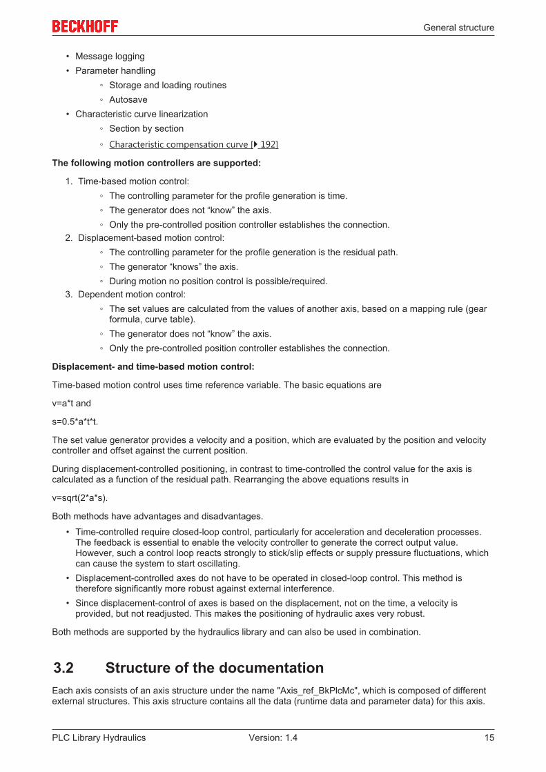
The following motion controllers are supported:
1. Time-based motion control:◦ The controlling parameter for the profile generation is time.◦ The generator does not “know” the axis.◦ Only the pre-controlled position controller establishes the connection.
2. Displacement-based motion control:◦ The controlling parameter for the profile generation is the residual path.◦ The generator “knows” the axis.◦ During motion no position control is possible/required.
3. Dependent motion control:◦ The set values are calculated from the values of another axis, based on a mapping rule (gear
formula, curve table).◦ The generator does not “know” the axis.◦ Only the pre-controlled position controller establishes the connection.
Displacement- and time-based motion control:
Time-based motion control uses time reference variable. The basic equations are
v=a*t and
s=0.5*a*t*t.
The set value generator provides a velocity and a position, which are evaluated by the position and velocitycontroller and offset against the current position.
During displacement-controlled positioning, in contrast to time-controlled the control value for the axis iscalculated as a function of the residual path. Rearranging the above equations results in
v=sqrt(2*a*s).
Both methods have advantages and disadvantages.
• Time-controlled require closed-loop control, particularly for acceleration and deceleration processes.The feedback is essential to enable the velocity controller to generate the correct output value.However, such a control loop reacts strongly to stick/slip effects or supply pressure fluctuations, whichcan cause the system to start oscillating.
• Displacement-controlled axes do not have to be operated in closed-loop control. This method istherefore significantly more robust against external interference.
• Since displacement-control of axes is based on the displacement, not on the time, a velocity isprovided, but not readjusted. This makes the positioning of hydraulic axes very robust.
Both methods are supported by the hydraulics library and can also be used in combination.
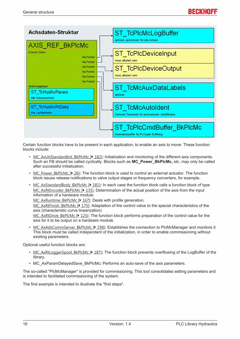
3.2 Structure of the documentationEach axis consists of an axis structure under the name "Axis_ref_BkPlcMc", which is composed of differentexternal structures. This axis structure contains all the data (runtime data and parameter data) for this axis.
General structure
PLC Library Hydraulics16 Version: 1.4
Certain function blocks have to be present in each application, to enable an axis to move. These functionblocks include:
• MC_AxUtiStandardInit_BkPlcMc [} 182]: Initialization and monitoring of the different axis components.Such an FB should be called cyclically. Blocks such as MC_Power_BkPlcMc, etc. may only be calledafter successful initialization.
• MC_Power_BkPlcMc [} 26]: The function block is used to control an external actuator. The functionblock issues release notifications to valve output stages or frequency converters, for example.
• MC_AxStandardBody_BkPlcMc [} 181]: In each case the function block calls a function block of typeMC_AxRtEncoder_BkPlcMc [} 135]: Determination of the actual position of the axis from the inputinformation of a hardware module.MC_AxRuntime_BkPlcMc [} 167]: Deals with profile generation.MC_AxRtFinish_BkPlcMc [} 175]: Adaptation of the control value to the special characteristics of theaxis (characteristic curve linearization)MC_AxRtDrive_BkPlcMc [} 125]: The function block performs preparation of the control value for theaxis for it to be output on a hardware module.
• MC_AxAdsCommServer_BkPlcMc [} 198]: Establishes the connection to PlcMcManager and monitors it.This block must be called independent of the initialization, in order to enable commissioning withoutexisting parameters.
Optional useful function blocks are:
• MC_AxRtLoggerSpool_BkPlcMc [} 187]: The function block prevents overflowing of the LogBuffer of thelibrary.
• MC_AxParamDelayedSave_BkPlcMc: Performs an auto-save of the axis parameters.
The so-called "PlcMcManager" is provided for commissioning. This tool consolidates setting parameters andis intended to facilitated commissioning of the system.
The first example is intended to illustrate the "first steps".
General structure
PLC Library Hydraulics 17Version: 1.4
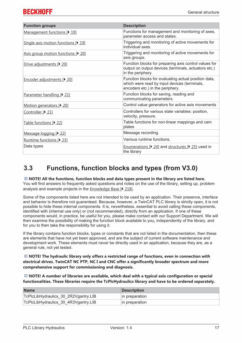
Function groups DescriptionManagement functions [} 19] Functions for management and monitoring of axes,
parameter access and states.Single axis motion functions [} 19] Triggering and monitoring of active movements for
individual axes.Axis group motion functions [} 20] Triggering and monitoring of active movements for
axis groups.Drive adjustments [} 20] Function blocks for preparing axis control values for
output on output devices (terminals, actuators etc.)in the periphery.
Encoder adjustments [} 20] Function blocks for evaluating actual position data,which were read by input devices (terminals,encoders etc.) in the periphery.
Parameter handling [} 21] Function blocks for saving, reading andcommunicating parameters.
Motion generators [} 20] Control value generators for active axis movements
Controller [} 21] Controllers for various state variables: position,velocity, pressure.
Table functions [} 22] Table functions for non-linear mappings and camplates
Message logging [} 22] Message recording.
Runtime functions [} 23] Various runtime functions.Data types Enumerations [} 24] and structures [} 25] used in
the library
3.3 Functions, function blocks and types (from V3.0)NOTE! All the functions, function blocks and data types present in the library are listed here.
You will find answers to frequently asked questions and notes on the use of the library, setting up, problemanalysis and example projects in the Knowledge Base [} 218].
Some of the components listed here are not intended to be used by an application. Their presence, interfaceand behavior is therefore not guaranteed. Because, however, a TwinCAT PLC library is strictly open, it is notpossible to hide these internal components. It is, nevertheless, essential to avoid calling these components,identified with (internal use only) or (not recommended), directly from an application. If one of thesecomponents would, in practice, be useful for you, please make contact with our Support Department. We willthen examine the possibility of making the function block available to you, independently of the library, andfor you to then take the responsibility for using it.
If the library contains function blocks, types or constants that are not listed in the documentation, then theseare elements that have not yet been approved, and are the subject of current software maintenance anddevelopment work. These elements must never be directly used in an application, because they are, as ageneral rule, not yet tested.
NOTE! The hydraulic library only offers a restricted range of functions, even in connection withelectrical drives. TwinCAT NC PTP, NC I and CNC offer a significantly broader spectrum and morecomprehensive support for commissioning and diagnosis.
NOTE! A number of libraries are available, which deal with a typical axis configuration or specialfunctionalities. These libraries require the TcPlcHydraulics library and have to be ordered separately.
Name DescriptionTcPlcLibHydraulics_30_2R2Vgantry.LIB in preparationTcPlcLibHydraulics_30_4R3Vgantry.LIB in preparation

General structure
PLC Library Hydraulics18 Version: 1.4
PLC open Motion Control
The function blocks listed here are oriented towards:
Technical Specification
PLCopen - Technical Committee 2 - Task Force
Function blocks for motion control
Part 1 Version 1.1 and Part 2 Version 0.99F (definition not yet finalized)
The names of these function blocks begin with MC_ and end with _BkPlcMc.
NOTE! Parts of the PLCopen definitions have not yet been finalized. Future versions of the librarymay be subject to modifications. Such modifications may relate to
• Names, behavior or even existence of functions, function blocks or derived data types• Names, behavior, types or existence of input or output signals

General structure
PLC Library Hydraulics 19Version: 1.4
Administrative Function blocks
Name DescriptionMC_CamTableSelect_BkPlcMc [} 46] The function block initializes a variable of type
ST_TcPlcMcCamId, thereby preparing a cam plate forthe coupling of two axes.
MC_Power_BkPlcMc [} 26] Function block to control an external actuator.
MC_ReadActualPosition_BkPlcMc [} 28] The actual position of an axis is determined.
MC_ReadActualTorque_BkPlcMc [} 29] The actual force or the actual pressure of an axis isdetermined.
MC_ReadActualVelocity_BkPlcMc [} 30] The actual velocity of an axis is determined.
MC_ReadAxisError_BkPlcMc [} 30] The current error code of an axis is found.
MC_ReadBoolParameter_BkPlcMc [} 31] The boolean parameters of an axis are read.
MC_ReadDigitalOutput_BkPlcMc [} 32] The current state of a digital output of a cam controller isdetermined.
MC_ReadParameter_BkPlcMc [} 33] The non-boolean parameters of an axis are read.
MC_ReadStatus_BkPlcMc [} 34] The state of the axis is decoded.
MC_Reset_BkPlcMc [} 36] The axis is placed in a state ready for operation.
MC_ResetAndStop_BkPlcMc [} 36] The axis is placed in a state ready for operation and isstationary.
MC_SetOverride_BkPlcMc [} 37] The axis override is set.
MC_SetPosition_BkPlcMc [} 39] The actual position of the axis is set.
MC_SetReferenceFlag_BkPlcMc [} 40] The referencing flag of the axis is defined. (Function isnot defined by PLCopen)
MC_WriteBoolParameter_BkPlcMc [} 41] The boolean parameters of an axis are written.
MC_WriteDigitalOutput_BkPlcMc [} 42] The current state of a digital output of a cam controller isdefined.
MC_WriteParameter_BkPlcMc [} 43] The non-boolean parameters of an axis are written.
Motion Function blocks, Single Axis
Name DescriptionMC_DigitalCamSwitch_BkPlcMc [} 48] Generation of software cams as a function of position,
direction of travel and velocity of an axis.MC_EmergencyStop_BkPlcMc [} 50] Stopping a movement without reaching the target
position. (Function is not defined by PLCopen)MC_Halt_BkPlcMc [} 56] Stopping a movement without reaching the target
position.MC_Home_BkPlcMc [} 57] Initiation and monitoring of a reference travel.
MC_ImediateStop_BkPlcMc [} 59] Stopping a movement without reaching the targetposition. (Function is not defined by PLCopen)
MC_MoveAbsolute_BkPlcMc [} 60] Start and monitoring of a positioning process at aspecifiable velocity to absolutely stated target co-ordinates.
MC_MoveJoySticked_BkPlcMc [} 62] Starting and controlling of an axis movement with aproportional control unit. (Function is not defined byPLCopen)
MC_MoveRelative_BkPlcMc [} 63] Start and monitoring of a positioning process at aspecifiable velocity over an absolutely stated distance.
MC_MoveVelocity_BkPlcMc [} 64] Start and monitoring of a positioning process at aspecifiable velocity but with no specified target.
MC_Stop_BkPlcMc [} 66] Stopping a movement without reaching the targetposition.

General structure
PLC Library Hydraulics20 Version: 1.4
Motion Function blocks, Multiple Axis
Name DescriptionMC_CamIn_BkPlcMc [} 44] The function block starts and monitors a cam plates
coupling between two axes.MC_CamOut_BkPlcMc [} 45] The function block releases a cam plate coupling
between two axes.MC_GearIn_BkPlcMc [} 51] Start and monitoring of the gear coupling of two axes.
MC_GearInPos_BkPlcMc [} 53] On-the-fly gear coupling of two axes.
MC_GearOut_BkPlcMc [} 55] Cancelling the gear coupling of two axes.
System Function blocks
Name DescriptionMC_AxRtDrive_BkPlcMc [} 125] Preparation of the control value of the axis for output on a
hardware module, mapping information.MC_AxRtEncoder_BkPlcMc [} 135] Determination of the actual position of the axis from the
input information of a hardware module, mappinginformation.
MC_AxRtFinish_BkPlcMc [} 175] Adaptation of the generated control value to the specialfeatures of the axis.
MC_AxRtFinishLinear_BkPlcMc [} 176] Adjustment of the generated control value to the specialfeatures of the axis, taking into account a characteristiccurve.
MC_AxRuntime_BkPlcMc [} 167] Control value generation for the axis.
System function blocks, other actual values
Name DescriptionMC_AxRtReadForceDiff_BkPlcMc [} 152] Determination of the differential actual force of an axis.
MC_AxRtReadForceSingle_BkPlcMc [} 154] Determination of the one-sided actual force of an axis.
MC_AxRtReadPressureDiff_BkPlcMc [} 156] Determination of the differential actual pressure of anaxis.
MC_AxRtReadPressureSingle_BkPlcMc [} 158] Determination of the one-sided actual pressure of anaxis.
General structure
PLC Library Hydraulics 21Version: 1.4
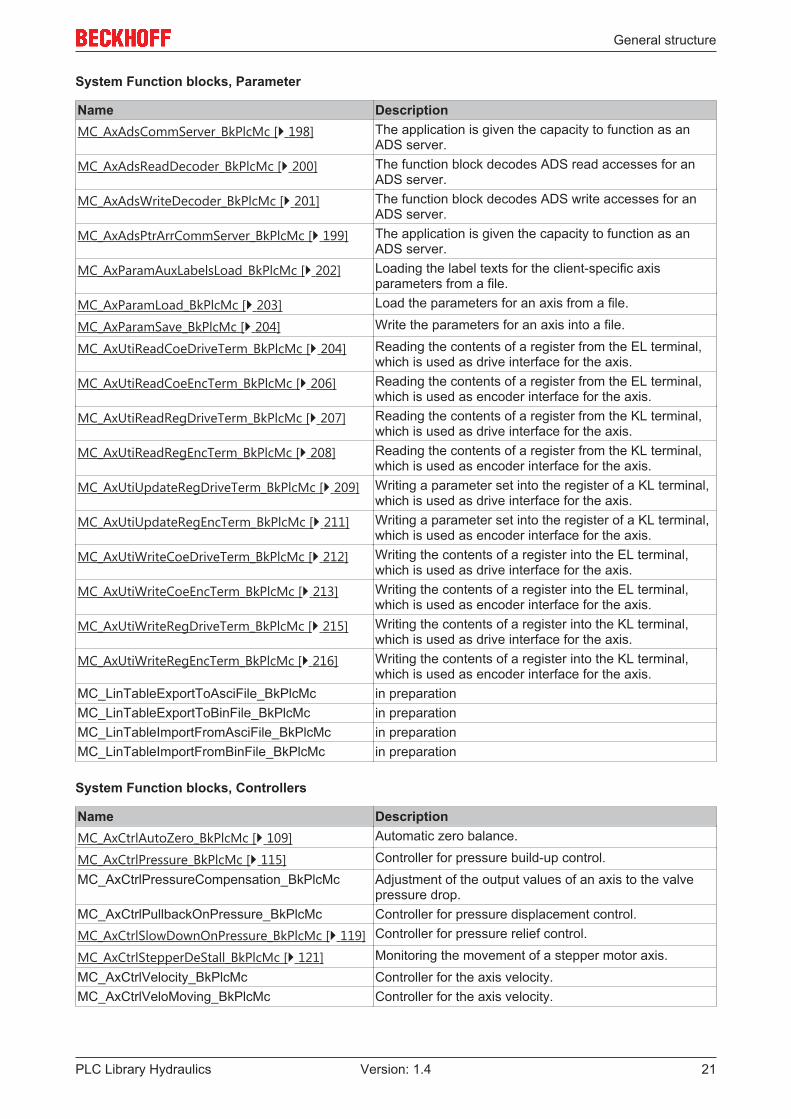
System Function blocks, Parameter
Name DescriptionMC_AxAdsCommServer_BkPlcMc [} 198] The application is given the capacity to function as an
ADS server.MC_AxAdsReadDecoder_BkPlcMc [} 200] The function block decodes ADS read accesses for an
ADS server.MC_AxAdsWriteDecoder_BkPlcMc [} 201] The function block decodes ADS write accesses for an
ADS server.MC_AxAdsPtrArrCommServer_BkPlcMc [} 199] The application is given the capacity to function as an
ADS server.MC_AxParamAuxLabelsLoad_BkPlcMc [} 202] Loading the label texts for the client-specific axis
parameters from a file.MC_AxParamLoad_BkPlcMc [} 203] Load the parameters for an axis from a file.
MC_AxParamSave_BkPlcMc [} 204] Write the parameters for an axis into a file.
MC_AxUtiReadCoeDriveTerm_BkPlcMc [} 204] Reading the contents of a register from the EL terminal,which is used as drive interface for the axis.
MC_AxUtiReadCoeEncTerm_BkPlcMc [} 206] Reading the contents of a register from the EL terminal,which is used as encoder interface for the axis.
MC_AxUtiReadRegDriveTerm_BkPlcMc [} 207] Reading the contents of a register from the KL terminal,which is used as drive interface for the axis.
MC_AxUtiReadRegEncTerm_BkPlcMc [} 208] Reading the contents of a register from the KL terminal,which is used as encoder interface for the axis.
MC_AxUtiUpdateRegDriveTerm_BkPlcMc [} 209] Writing a parameter set into the register of a KL terminal,which is used as drive interface for the axis.
MC_AxUtiUpdateRegEncTerm_BkPlcMc [} 211] Writing a parameter set into the register of a KL terminal,which is used as encoder interface for the axis.
MC_AxUtiWriteCoeDriveTerm_BkPlcMc [} 212] Writing the contents of a register into the EL terminal,which is used as drive interface for the axis.
MC_AxUtiWriteCoeEncTerm_BkPlcMc [} 213] Writing the contents of a register into the EL terminal,which is used as encoder interface for the axis.
MC_AxUtiWriteRegDriveTerm_BkPlcMc [} 215] Writing the contents of a register into the KL terminal,which is used as drive interface for the axis.
MC_AxUtiWriteRegEncTerm_BkPlcMc [} 216] Writing the contents of a register into the KL terminal,which is used as encoder interface for the axis.
MC_LinTableExportToAsciFile_BkPlcMc in preparationMC_LinTableExportToBinFile_BkPlcMc in preparationMC_LinTableImportFromAsciFile_BkPlcMc in preparationMC_LinTableImportFromBinFile_BkPlcMc in preparation
System Function blocks, Controllers
Name DescriptionMC_AxCtrlAutoZero_BkPlcMc [} 109] Automatic zero balance.
MC_AxCtrlPressure_BkPlcMc [} 115] Controller for pressure build-up control.MC_AxCtrlPressureCompensation_BkPlcMc Adjustment of the output values of an axis to the valve
pressure drop.MC_AxCtrlPullbackOnPressure_BkPlcMc Controller for pressure displacement control.MC_AxCtrlSlowDownOnPressure_BkPlcMc [} 119] Controller for pressure relief control.
MC_AxCtrlStepperDeStall_BkPlcMc [} 121] Monitoring the movement of a stepper motor axis.MC_AxCtrlVelocity_BkPlcMc Controller for the axis velocity.MC_AxCtrlVeloMoving_BkPlcMc Controller for the axis velocity.

General structure
PLC Library Hydraulics22 Version: 1.4
System Function blocks, TableFunctions
Name DescriptionMC_AxTableFromAsciFile_BkPlcMc [} 166] Reading the content of table from a text file.
MC_AxTableFromBinFile_BkPlcMc [} 165] Reading the content of table from a binary file.
MC_AxTableReadOutNonCyclic_BkPlcMc [} 164] Function block for determining the slave values assignedto a master value with the aid of a table.
MC_AxTableToAsciFile_BkPlcMc [} 162] Writing the contents of a table to text file.
MC_AxTableToBinFile_BkPlcMc [} 161] Writing the contents of a table to a binary file.
System Function blocks, Message Logging
Name DescriptionMC_AxRtLogAxisEntry_BkPlcMc [} 184] An axis-related message is entered in the LogBuffer of
the library.MC_AxRtLogClear_BkPlcMc [} 185] Clear and initialize all entries in the LogBuffer.
MC_AxRtLogEntry_BkPlcMc [} 185] A message is entered in the LogBuffer of the library.
MC_AxRtLoggerDespool_BkPlcMc [} 186] Ensure the minimum number of free messages in theLogBuffer of the library.
MC_AxRtLoggerRead_BkPlcMc [} 186] Reading a message from the LogBuffer of the library.
MC_AxRtLoggerSpool_BkPlcMc [} 187] Transferring messages from the LogBuffer of the libraryinto the Windows event viewer.

General structure
PLC Library Hydraulics 23Version: 1.4
System function blocks, runtime functions
Name DescriptionMC_AxRtCheckSyncDistance_BkPlcMc [} 174] Monitoring of the distance between the referencing cam
and zero pulse.MC_AxRtCmdBufferExecute_BkPlcMc in preparationMC_AxRtCommandsLocked_BkPlcMc [} 187] in preparation
MC_AxRtGoErrorState_BkPlcMc [} 178] (not recommended) The axis is placed into an error state.
MC_AxRtMoveChecking_BkPlcMc [} 178] Monitoring the movement of an axis.
MC_AxRtSetDirectOutput_BkPlcMc [} 179] Direct output of a control value.
MC_AxRtSetExtGenValues_BkPlcMc [} 180] Supplying an axis with command variables, which do notoriginate from the axis' own generator.
MC_AxStandardBody_BkPlcMc [} 181] Calls the usual sub-components for an axis (encoder,generator, finish, drive).
MC_AxUtiAutoIdent_BkPlcMc [} 192] Automatic determination of axis parameters.MC_AxUtiAutoIdentSlave_BkPlcMc in preparation: Automatic determination of slave axis
parameters.MC_AxUtiAverageDerivative_BkPlcMc [} 188] Determination of the derivative of value through numeric
differentiation over than one cycle.MC_AxUtiPT1_BkPlcMc [} 189] Calculation of a first-order low-pass.
MC_AxUtiPT2_BkPlcMc [} 190] Calculation of a second-order low-pass.
MC_AxUtiSlewRateLimitter_BkPlcMc [} 190] Generation of a rise-limited ramp.
MC_AxUtiSlidingAverage_BkPlcMc [} 191] Determination of a moving average.
MC_AxUtiStandardInit_BkPlcMc [} 182] Initialization and monitoring of axis components.
MC_FunctionGeneratorFD_BkPlcMc [} 159] A function generator.
MC_FunctionGeneratorSetFrq_BkPlcMc [} 160] Updates the operating frequency of a time base for oneor several function generators.
MC_FunctionGeneratorTB_BkPlcMc [} 161] Updates a time base for one or several functiongenerators.

General structure
PLC Library Hydraulics24 Version: 1.4
Data types: Enumerations
Name DescriptionE_TcMcCurrentStep [} 71] This enumeration returns codes for the internal states of
the control value generators.E_TcMcDriveType [} 72] The constants in this enumeration are used to identify the
hardware used to output the control values for an axis.E_TcMcEncoderType [} 75] The constants in this enumeration are used to identify the
hardware used to acquire the actual values for an axis.E_TcMCFbState [} 78] This enumeration supplies codes for the current state of
an axis.E_TcMcHomingType [} 79] This enumeration supplies codes for the referencing
method used by an axis.E_TcMCParameter [} 79] The constants listed here are used for numbering
parameters.E_TcMcPressureReadingMode [} 89] The constants in this list determine which actual value in
the ST_TcHydAxRtData structure of the axis is to beupdated with the result of a pressure or forcemeasurement.
E_TcMcProfileType [} 88] The constants listed here are used for identifying controlvalue generators.
E_TcPlcBufferedCmdType_BkPlcMc [} 69] In preparation: The constants in this list are used toidentify buffered axis commands.
MC_BufferMode_BkPlcMc [} 89] The constants in this list are used for controlling blendingaccording to PLC Open.
MC_Direction_BkPlcMc [} 90] This enumeration supplies codes for the direction ofmovement if this information is not contained in otherdata or cannot be in determined on the basis of thesituation.
MC_HomingMode_BkPlcMc [} 91] This enumeration returns codes for specification of thereferencing method.
MC_StartMode_BkPlcMc [} 91] The constants in this list are used for identifying themodes during axis startups.

General structure
PLC Library Hydraulics 25Version: 1.4
Data types: Structures
Name DescriptionAxis_Ref_BkPlcMc [} 67] A variable of this type contains all the necessary
variables or pointers to variables that are associated withan axis.
CAMSWITCH_REF_BkPlcMc [} 69] A variable of this type is transferred to anMC_DigitalCamSwitch_BkPlcMc [} 48] function block.
MC_CAM_ID_BkPlcMc [} 90] A variable of this type contains the description of a camplate prepared for coupling.
MC_CAM_REF_BkPlcMc [} 90] A variable of this type contains the description of aprovided cam plate.
OUTPUT_REF_BkPlcMc [} 92] A variable of this type contains output data of anMC_DigitalCamSwitch_BkPlcMc [} 48] function block.
ST_FunctionGeneratorFD_BkPlcMc [} 92] A variable of this type contains parameters for definingthe output signals of a function generator.
ST_FunctionGeneratorTB_BkPlcMc [} 92] A variable of this type contains parameter for defining atime base for a function generator.
ST_TcMcAutoIdent [} 93] A variable of this type contains the parameters for anMC_AxUtiAutoIdent_BkPlcMc [} 192] function block.
ST_TcMcAuxDataLabels [} 103] A variable of this type contains label texts for the client-specific axis parameters.
ST_TcHydAxParam [} 93] A variable of this type contains all the parameters for anaxis.
ST_TcHydAxRtData [} 99] A variable of this type contains the runtime data for anaxis.
ST_TcPlcMcLogBuffer [} 107] A variable with this structure forms the LogBuffer of thelibrary.
ST_TcPlcMcLogEntry [} 108] A variable with this structure contains a message of theLogBuffer of the library.
ST_TcPlcDeviceInput [} 104] This structure contains the input image variables of anaxis.
ST_TcPlcDeviceOutput [} 106] This structure contains the output image variables of anaxis.
ST_TcPlcRegDataItem [} 108] This structure contains a parameter set for a KL terminal.
ST_TcPlcRegDataTable [} 109] This structure contains a parameter for a KL terminal.
TRACK_REF_BkPlcMc [} 109] In preparation.

PLCopen Motion Control
PLC Library Hydraulics26 Version: 1.4
4 PLCopen Motion Control
4.1 Administrative
4.1.1 MC_Power_BkPlcMc (from V3.0)
The function block is used to control an external actuator. Further information on this topic can be foundunder FAQ #9 [} 227].VAR_INPUT Enable: BOOL; Enable_Positive: BOOL; Enable_Negative: BOOL; BufferMode: MC_BufferMode_BkPlcMc:=Aborting_BkPlcMc; (ab/from V3.0.8)END_VARVAR_OUTPUT Busy: BOOL; Status: BOOL; Error: BOOL; ErrorID: UDINT;END_VARVAR_INOUT Axis: Axis_Ref_BkPlcMc;END_VAR
Enable: A TRUE at this input activates an external actuator of an axis.
Enable_Positive: A TRUE at this input activates the directional enable of an external actuator of an axis formovements in a positive direction.
Enable_Negative: A TRUE at this input activates the directional enable of an external actuator of an axis formovements in a negative direction.
BufferMode: Reserved. This input is provided in preparation for a future build. It should currently either notbe assigned or assigned the constant Aborting_BkPlcMc. (from V3.0.8)
Busy: Indicates that a command is being processed.
Status: Readiness for operation is indicated here.
Error: The occurrence of an error is indicated here.
ErrorID: An encoded error message is provided here.
Axis: Here, the address of a variable of type Axis_Ref_BkPlcMc [} 67] should be transferred.
Behavior of the function block:
This function block is used to control external actuators. These can be modules for valve control (the valve'sonboard output stage or switch cabinet assembly), frequency converters or servoamplifiers. These devicesusually require a digital signal to enable the output of energy through a power stage. Depending on thedesign of the device, it is also possible for the "positive" and "negative" movement directions to beindividually activated.

PLCopen Motion Control
PLC Library Hydraulics 27Version: 1.4
The function block's input signals are passed on through the interface to the peripheral device. Enable alsoactivates error monitoring.
The function block investigates the axis interface that has been passed to it every time it is called. A numberof problems can be detected and reported during this process:
• If the value iTcMc_DriveAx2000_XXXXX is set under nDrive_Type in pStAxParams, the followingprocedure is applied:
◦ If one of the pointers pStDeviceOutput or pStDeviceInput in Axis_Ref_BkPlcMc [} 67] is notinitialized, the block responds with Error and ErrorID:=dwTcHydErrCdPtrPlcDriveIn ordwTcHydErrCdPtrPlcDriveOut. Status is then FALSE.
◦ If an error is detected in the communication with the AX device or an error message occurs inthe pStDeviceInput interface of the AX device, the function block responds with Error and anErrorID, which is defined in the global constants [} 241] of the library. Status is then FALSE,and the axis is set to an error state with the axis error dwTcHydErrCdDriveNotReady.
◦ Otherwise, the value of Enable is returned as the Status.• If the value iTcMc_DriveKL2531 or iTcMc_DriveKL2541 is set under nDrive_Type in pStAxParams, the
following procedure is applied:
◦ The pointers pStDeviceOutput and or pStDeviceInput Axis_Ref_BkPlcMc [} 67] are checked. Ifthese pointers have not been initialised, the function block responds with Error andErrorID:=dwTcHydErrCdPtrPlcDriveIn or dwTcHydErrCdPtrPlcDriveOut. Status is thenFALSE.
◦ If an error is detected in the communication with the I/O terminal or an error message occurs inthe pStDeviceInput interface of the terminal, the function block responds with Error and anErrorID, which is defined in the in global constants [} 241] of the library. Status is thenFALSE, and the axis is set to an error state with the axis error dwTcHydErrCdDriveNotReady.
◦ Enable is used to activate the terminal output stage through a bit inpStDeviceOutput.bTerminalCtrl. The ready signal in bTerminalCtrl.bTerminalState is returnedas Status.
◦ If the drive interface is operating without error, the value of Enable_Positive is entered withthe mask dwTcHydDcDwFdPosEna in the nDeCtrlDWord of pStAxRtData.
◦ If the drive interface is operating without error, the value of Enable_Negative is entered withthe mask dwTcHydDcDwFdNegEna in the nDeCtrlDWord of pStAxRtData.
• Otherwise the pointers pStDeviceInput and pStDeviceOutput in Axis_Ref_BkPlcMc [} 67] are checked.If these pointers have not been initialised, the function block responds with Error andErrorID:=dwTcHydErrCdPtrPlcDriveIn or dwTcHydErrCdPtrPlcDriveOut. Status is then FALSE.
◦ Otherwise, the value of bPowerOk from pStDeviceInput is returned as the Status.• If the drive interface is operating without error, the value of Enable is entered with the mask
dwTcHydDcDwCtrlEnable in the nDeCtrlDWord of pStAxRtData.• If the drive interface is operating without error, the value of Enable_Positive is entered with the mask
dwTcHydDcDwFdPosEna in the nDeCtrlDWord of pStAxRtData.• If the drive interface is operating without error, the value of Enable_Negative is entered with the mask
dwTcHydDcDwFdNegEna in the nDeCtrlDWord of pStAxRtData.
NOTE! This function block requires no time for executing its tasks. The output Busy will neverassume the value TRUE and only exists for compatibility reasons.

PLCopen Motion Control
PLC Library Hydraulics28 Version: 1.4
4.1.2 MC_ReadActualPosition_BkPlcMc (from V3.0)
The function block determines the current position of an axis.VAR_INPUT Enable: BOOL;END_VARVAR_OUTPUT Busy: BOOL; Valid: BOOL; Error: BOOL; ErrorID: UDINT; Position: LREAL;END_VARVAR_INOUT Axis: Axis_Ref_BkPlcMc;END_VAR
Enable: Updating of the position value is initiated by a positive edge at this input.
Busy: Indicates that a command is being processed.
Valid: Successful determination of the actual position is indicated here.
Error: The occurrence of an error is indicated here.
ErrorID: An encoded indication of the cause of the error is provided here.
Position: [mm] The actual position.
Axis: Here, the address of a variable of type Axis_Ref_BkPlcMc [} 67] should be transferred.
Behavior of the function block
The function block is activated by a positive edge at Enable, and investigates the axis interface that hasbeen passed to it. A number of problems can be detected and reported during this process:
• If the axis is already in a fault state, and if the cause lies with an encoder problem, it responds withError and ErrorID:=the encoder's error code.
The actual position is determined and reported with Valid if these checks can be carried out withoutproblems.
A negative edge at Enable clears all the pending output signals.
NOTE! This function block requires no time for executing its tasks. The output Busy will neverassume the value TRUE and only exists for compatibility reasons.

PLCopen Motion Control
PLC Library Hydraulics 29Version: 1.4
4.1.3 MC_ReadActualTorque_BkPlcMc (from V3.0)
The function block determines the current actual force or actual pressure of an axis.VAR_INPUT Enable: BOOL;END_VARVAR_OUTPUT Valid: BOOL; Busy: BOOL; Error: BOOL; ErrorID: UDINT; Torque: LREAL;END_VARVAR_INOUT Axis: Axis_Ref_BkPlcMc;END_VAR
Enable: A rising edge at this input triggers an update of the actual value.
Valid: This indicates successful determination of the actual value.
Busy: This output TRUE while the command is being processed.
Error: The occurrence of an error is indicated here.
ErrorID: An encoded indication of the cause of the error is provided here.
Torque: The actual force or actual pressure.
Axis: Here, the address of a variable of type Axis_Ref_BkPlcMc [} 67] should be transferred.
Behavior of the function block:
The function block is activated by a rising edge at Enable, and investigates the axis interface that has beenpassed to it. A number of problems can be detected and reported during this process:
• If the axis is already in a fault state, and if the cause lies with an encoder problem, it responds withError and ErrorID:=the encoder's error code.
If these checks were completed without problem, the actual force or the actual pressure is determined, andValid is reported.
A falling edge at Enable clears all the pending output signals.
NOTE! This function block requires no time for executing its tasks. The output Busy will neverassume the value TRUE and only exists for compatibility reasons.

PLCopen Motion Control
PLC Library Hydraulics30 Version: 1.4
4.1.4 MC_ReadActualVelocity_BkPlcMc (from V3.0)
The function block determines the current velocity of an axis.VAR_INPUT Enable: BOOL;END_VARVAR_OUTPUT Valid: BOOL; Busy: BOOL; Error: BOOL; ErrorID: UDINT; Velocity: LREAL;END_VARVAR_INOUT Axis: Axis_Ref_BkPlcMc;END_VAR
Enable: A positive edge at this input triggers an update of the velocity value.
Valid: This indicates successful determination of the velocity.
Busy: This output is TRUE while the command is being processed.
Error: The occurrence of an error is indicated here.
ErrorID: An encoded indication of the cause of the error is provided here.
Velocity: [mm/s] The actual velocity.
Axis: Here, the address of a variable of type Axis_Ref_BkPlcMc [} 67] should be transferred.
Behavior of the function block
The function block is activated by a positive edge at Enable, and investigates the axis interface that hasbeen passed to it. A number of problems can be detected and reported during this process:
• If the axis is already in a fault state, and if the cause lies with an encoder problem, it responds withError and ErrorID:=the encoder's error code.
The velocity is determined and reported with Valid if these checks can be carried out without problems.
A negative edge at Enable clears all the pending output signals.
NOTE! This function block requires no time for executing its tasks. The output Busy will neverassume the value TRUE and only exists for compatibility reasons.
4.1.5 MC_ReadAxisError_BkPlcMc (from V3.0)

PLCopen Motion Control
PLC Library Hydraulics 31Version: 1.4
This function block determines the current error code of an axis.VAR_INPUT Enable: BOOL;END_VARVAR_OUTPUT Busy: BOOL; Done: BOOL; Error: BOOL; ErrorID: UDINT; AxisErrorID:UDINT;END_VARVAR_INOUT Axis: Axis_Ref_BkPlcMc;END_VAR
Enable: TRUE at this input triggers an update of the error code.
Busy: Indicates that a command is being processed.
Done: Successful determination of the actual position is indicated here.
Error: Indicates TRUE, if the function block was unable to execute the required function.
ErrorID: Provides a coded cause of error, if the function block was unable to execute the required function.
AxisErrorID: Provides the current error code [} 236] of the axis.
Axis: Here, the address of a variable of type Axis_Ref_BkPlcMc [} 67] should be transferred.
Behavior of the function block:
If Enable is TRUE, the function block checks the transferred axis interface. The current error code isreported as AxisErrorID. If Enable is FALSE, the function block cancels all pending output signals.
NOTE! This function block requires no time and no preconditions for executing its tasks. Theoutputs Error and Busy will never assume the value TRUE and only exist for compatibility reasons.
4.1.6 MC_ReadBoolParameter_BkPlcMc (from V3.0)
This function block reads the boolean parameters of an axis. The function block MC_ReadParameter_BkPlcMc[} 33] is available for non-boolean parameters.VAR_INPUT Enable: BOOL; ParameterNumber: INT;END_VARVAR_OUTPUT Busy: BOOL; Done: BOOL; Error: BOOL; ErrorID: UDINT; Value: BOOL;END_VARVAR_INOUT Axis: Axis_Ref_BkPlcMc;END_VAR
Enable: A reading process is initiated by a rising edge at this input.

PLCopen Motion Control
PLC Library Hydraulics32 Version: 1.4
ParameterNumber: This code number specifies the parameter that is to be read. Only named constantsfrom E_TcMCParameter [} 79] should be used.
Busy: Indicates that a command is being processed.
Done: Successful execution of the reading process is indicated here.
Error: The occurrence of an error is indicated here.
ErrorID: An encoded indication of the cause of the error is provided here.
Value: The value of the parameter is made available here.
Axis: Here, the address of a variable of type Axis_Ref_BkPlcMc [} 67] should be transferred.
Behavior of the function block:
The function block is activated by a rising edge at Enable, and investigates the axis interface that has beenpassed to it. A number of problems can be detected and reported during this process:
• If an unsupported value is given to ParameterNumber the function block responds with Error andErrorID:=dwTcHydErrCdNotSupport.
The desired parameter value is made available at Value, and Done is asserted if these checks can becarried out without problems.
A falling edge at Enable clears all the pending output signals.
NOTE! This function block requires no time for executing its tasks. The output Busy will neverassume the value TRUE and only exists for compatibility reasons.
4.1.7 MC_ReadDigitalOutput_BkPlcMc (from V3.0)
The function block determines the current state of a digital output of a cam controller.VAR_INPUT Enable: BOOL; OutputNumber: INT;END_VARVAR_OUTPUT Done: BOOL; Busy: BOOL; Error: BOOL; ErrorID: UDINT; Value: BOOL;END_VARVAR_INOUT Output: OUTPUT_REF_BkPlcMc;END_VAR
Enable: A rising edge at this input triggers an update of the state.
OutputNumber: The number of the output to be determined.
Valid: This indicates successful determination of the state.
Busy: This output TRUE while the command is being processed.
Error: The occurrence of an error is indicated here.

PLCopen Motion Control
PLC Library Hydraulics 33Version: 1.4
ErrorID: An encoded indication of the cause of the error is provided here.
Value: The state of the digital output.
Output: Here, the address of a variable of type OUTPUT_REF_BkPlcMc [} 92] should be transferred.
Behavior of the function block:
If Enable is TRUE, the function block checks the transferred parameters. During this process, a problemmay be detected and reported:
• If the value of OutputNumber is not within the permissible range [0..31], the response is Error withErrorID:=dwTcHydErrCdIllegalOutputNumber.
If these checks were carried out without problems, the state of the digital output is determined, and Valid isreported.
A falling edge at Enable clears all the pending output signals.
4.1.8 MC_ReadParameter_BkPlcMc (from V3.0)
This function block reads the non-boolean parameters of an axis. The function blockMC_ReadBoolParameter_BkPlcMc [} 31] is available for boolean parameters.VAR_INPUT Enable: BOOL; ParameterNumber: INT;END_VARVAR_OUTPUT Busy: BOOL; Done: BOOL; Error: BOOL; ErrorID: UDINT; Value: LREAL;END_VARVAR_INOUT Axis: Axis_Ref_BkPlcMc;END_VAR
Enable: A reading process is initiated by a rising edge at this input.
ParameterNumber: This code number specifies the parameter that is to be read. Only named constantsfrom E_TcMCParameter [} 79] should be used.
Busy: Indicates that a command is being processed.
Done: Successful execution of the reading process is indicated here.
Error: The occurrence of an error is indicated here.
ErrorID: An encoded indication of the cause of the error is provided here.
Value: The value of the parameter is made available here.
Axis: Here, the address of a variable of type Axis_Ref_BkPlcMc [} 67] should be transferred.
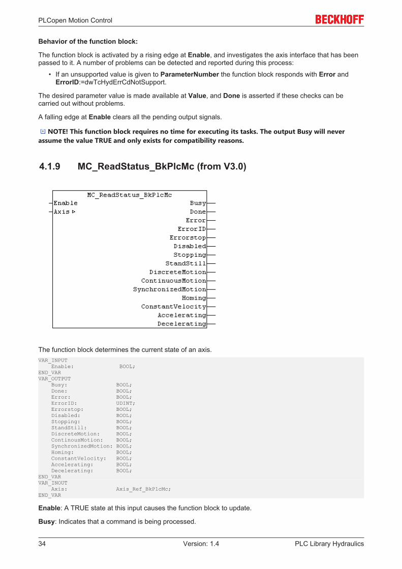
PLCopen Motion Control
PLC Library Hydraulics34 Version: 1.4
Behavior of the function block:
The function block is activated by a rising edge at Enable, and investigates the axis interface that has beenpassed to it. A number of problems can be detected and reported during this process:
• If an unsupported value is given to ParameterNumber the function block responds with Error andErrorID:=dwTcHydErrCdNotSupport.
The desired parameter value is made available at Value, and Done is asserted if these checks can becarried out without problems.
A falling edge at Enable clears all the pending output signals.
NOTE! This function block requires no time for executing its tasks. The output Busy will neverassume the value TRUE and only exists for compatibility reasons.
4.1.9 MC_ReadStatus_BkPlcMc (from V3.0)
The function block determines the current state of an axis.VAR_INPUT Enable: BOOL;END_VARVAR_OUTPUT Busy: BOOL; Done: BOOL; Error: BOOL; ErrorID: UDINT; Errorstop: BOOL; Disabled: BOOL; Stopping: BOOL; StandStill: BOOL; DiscreteMotion: BOOL; ContinousMotion: BOOL; SynchronizedMotion: BOOL; Homing: BOOL; ConstantVelocity: BOOL; Accelerating: BOOL; Decelerating: BOOL;END_VARVAR_INOUT Axis: Axis_Ref_BkPlcMc;END_VAR
Enable: A TRUE state at this input causes the function block to update.
Busy: Indicates that a command is being processed.

PLCopen Motion Control
PLC Library Hydraulics 35Version: 1.4
Done: Successful determination of the actual position is indicated here.
Error: This output reports any problems relating to the function of the function block.
ErrorID: Provides a coded cause of error, if the function block was unable to execute the required function.
Errorstop: This signal indicates that the axis associated with an error has been placed in a state in which itis not able to operate. This state can only be cleared by activating either a MC_Reset_BkPlcMc [} 36] or aMC_ResetAndStop_BkPlcMc [} 36] function block.
Disabled: This signal indicates whether the axis is enabled or disabled by its MC_Power_BkPlcMc [} 26]function block.
Stopping: This signal indicates that an active movement of the axis is being stopped by a MC_Stop_BkPlcMc[} 66] or by a MC_ResetAndStop_BkPlcMc [} 36] function block. This signal is cleared as soon as the axisis stationary.
StandStill: This signal indicates that the axis is neither in a fault state nor is it active.
DiscreteMotion: This signal indicates that the axis is executing an autonomous movement (not resultingfrom a coupling) with a defined target.
ContinousMotion: This signal indicates that the axis is executing an autonomous movement (not resultingfrom a coupling) with a defined velocity but not with a specified target.
SynchronizedMotion: This signal indicates that the axis is being controlled by a gear coupling.
Homing: This signal indicates that the axis is executing a reference travel.
ConstantVelocity: This signal indicates that the axis is being moved with constant velocity.
Accelerating: This signal indicates that the velocity of an axis is reaching a specified value. NOTE! This does not always mean that the velocity is increasing: when an axis that is already in
movement is started, it can happen that the axis accelerates in the direction opposite the currentmovement in order to achieve a specified velocity in the other direction. From the point of view of theoriginal movement this is a deceleration, although from the point of the current (new) movement it isstill an acceleration.
Decelerating: This signal indicates that the axis is reducing its velocity in order to continue a movement witha velocity lower than the current velocity, or in order to end it.
Axis: Here, the address of a variable of type Axis_Ref_BkPlcMc [} 67] should be transferred.
Behaviour of the function block:
If Enable is TRUE, the function block examines the transferred axis interface and decodes the internal stateinformation. A FALSE state at Enable clears all the pending output signals.
NOTE! This function block requires no time and no preconditions for executing its tasks. Theoutputs Error and Busy will never assume the value TRUE and only exist for compatibility reasons.
Note
Observe outputsThe outputs Error and ErrorID indicate the state of the function block, not that of the axis.
To read the current error code of the axis, an MC_ReadAxisError_BkPlcMc() [} 30] function block should beused.
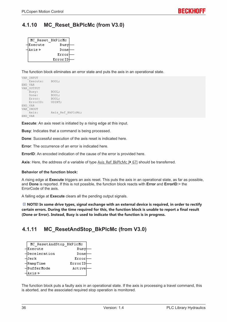
PLCopen Motion Control
PLC Library Hydraulics36 Version: 1.4
4.1.10 MC_Reset_BkPlcMc (from V3.0)
The function block eliminates an error state and puts the axis in an operational state.VAR_INPUT Execute: BOOL;END_VARVAR_OUTPUT Busy: BOOL; Done: BOOL; Error: BOOL; ErrorID: UDINT;END_VARVAR_INOUT Axis: Axis_Ref_BkPlcMc;END_VAR
Execute: An axis reset is initiated by a rising edge at this input.
Busy: Indicates that a command is being processed.
Done: Successful execution of the axis reset is indicated here.
Error: The occurrence of an error is indicated here.
ErrorID: An encoded indication of the cause of the error is provided here.
Axis: Here, the address of a variable of type Axis_Ref_BkPlcMc [} 67] should be transferred.
Behavior of the function block:
A rising edge at Execute triggers an axis reset. This puts the axis in an operational state, as far as possible,and Done is reported. If this is not possible, the function block reacts with Error and ErrorID:= theErrorCode of the axis.
A falling edge at Execute clears all the pending output signals.
NOTE! In some drive types, signal exchange with an external device is required, in order to rectifycertain errors. During the time required for this, the function block is unable to report a final result(Done or Error). Instead, Busy is used to indicate that the function is in progress.
4.1.11 MC_ResetAndStop_BkPlcMc (from V3.0)
The function block puts a faulty axis in an operational state. If the axis is processing a travel command, thisis aborted, and the associated required stop operation is monitored.
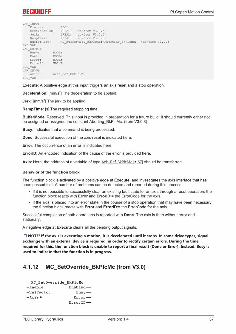
PLCopen Motion Control
PLC Library Hydraulics 37Version: 1.4
VAR_INPUT Execute: BOOL; Deceleration: LREAL; (ab/from V3.0.5) Jerk: LREAL; (ab/from V3.0.5) RampTime: LREAL; (ab/from V3.0.5) BufferMode: MC_BufferMode_BkPlcMc:=Aborting_BkPlcMc; (ab/from V3.0.8)END_VARVAR_OUTPUT Busy: BOOL; Done: BOOL; Error: BOOL; ErrorID: UDINT;END_VARVAR_INOUT Axis: Axis_Ref_BkPlcMc;END_VAR
Execute: A positive edge at this input triggers an axis reset and a stop operation.
Deceleration: [mm/s2] The deceleration to be applied.
Jerk: [mm/s3] The jerk to be applied.
RampTime: [s] The required stopping time.
BufferMode: Reserved. This input is provided in preparation for a future build. It should currently either notbe assigned or assigned the constant Aborting_BkPlcMc. (from V3.0.8)
Busy: Indicates that a command is being processed.
Done: Successful execution of the axis reset is indicated here.
Error: The occurrence of an error is indicated here.
ErrorID: An encoded indication of the cause of the error is provided here.
Axis: Here, the address of a variable of type Axis_Ref_BkPlcMc [} 67] should be transferred.
Behavior of the function block
The function block is activated by a positive edge at Execute, and investigates the axis interface that hasbeen passed to it. A number of problems can be detected and reported during this process:
• If it is not possible to successfully clear an existing fault state for an axis through a reset operation, thefunction block reacts with Error and ErrorID:= the ErrorCode for the axis.
• If the axis is placed into an error state in the course of a stop operation that may have been necessary,the function block reacts with Error and ErrorID:= the ErrorCode for the axis.
Successful completion of both operations is reported with Done. The axis is then without error andstationary.
A negative edge at Execute clears all the pending output signals.
NOTE! If the axis is executing a motion, it is decelerated until it stops. In some drive types, signalexchange with an external device is required, in order to rectify certain errors. During the timerequired for this, the function block is unable to report a final result (Done or Error). Instead, Busy isused to indicate that the function is in progress.
4.1.12 MC_SetOverride_BkPlcMc (from V3.0)

PLCopen Motion Control
PLC Library Hydraulics38 Version: 1.4
The function block sets the override of an axis.
NOTE! This function block only takes effect if the profile type iTcMc_ProfileCtrlBased is used.VAR_INPUT Enable: BOOL; VelFactor: LREAL;END_VARVAR_OUTPUT Enabled: BOOL; Busy: BOOL; Error: BOOL; ErrorID: UDINT;END_VARVAR_INOUT Axis: Axis_Ref_BkPlcMc;END_VAR
Enable: An active state at this input sets the override of the axis.
VelFactor: [1] The new override of the axis.
Enabled: This indicates the active state of the function block.
Busy: This output is TRUE while the command is being processed.
Error: The occurrence of an error is indicated here.
ErrorID: An encoded indication of the cause of the error is provided here.
Axis: Here, the address of a variable of type Axis_Ref_BkPlcMc [} 67] should be transferred.
Behavior of the function block
If the Enable state is active, the value transferred as VelOverride is limited to the range 0.0 to 1.0 andentered in Axis.pStAxParams^.fOverride. Enabled is set to TRUE.
A negative edge at Enable clears all outputs.

PLCopen Motion Control
PLC Library Hydraulics 39Version: 1.4
All velocity changes caused by an override change are limited according to the maximum permittedaccelerations and decelerations.
NOTE! In order to ensure reproducible behavior during the target approach, the override onlyreduces the travel speed to pStAxParams.fCreepSpeed. Therefore, it is not possible to stop the axismovement through an override of 0.0.
4.1.13 MC_SetPosition_BkPlcMc (from V3.0)
The function block sets the actual position of an axis.VAR_INPUT Execute: BOOL; Position: LREAL; Mode: BOOL;END_VARVAR_OUTPUT Done: BOOL; Busy: BOOL; Error: BOOL; ErrorID: UDINT;END_VAR

PLCopen Motion Control
PLC Library Hydraulics40 Version: 1.4
VAR_INOUT Axis: Axis_Ref_BkPlcMc;END_VAR
Execute: A positive edge at this input sets the actual position of the axis.
Position: [mm] The new actual position of the axis.
Mode: This parameter specifies the operating mode. If Mode = TRUE, the actual position is changed byPosition, if Mode = FALSE, the actual position is set to Position.
Done: This indicates successful processing of the command.
Busy: This output is TRUE while the command is being processed.
Error: The occurrence of an error is indicated here.
ErrorID: An encoded indication of the cause of the error is provided here.
Axis: Here, the address of a variable of type Axis_Ref_BkPlcMc [} 67] should be transferred.
Behavior of the function block
The function block is activated by a positive edge at Execute, and investigates the axis interface that hasbeen passed to it. A number of problems can be detected and reported during this process:
• Depending on the encoder type specified in Axis.pStAxParams^.nEnc_Type, eitherST_TcHydAxRtData.fEnc_RefShift or ST_TcHydAxParam.fEnc_ZeroShift is updated such that theactual position of the axis assumes the required value. If the encoder types is unknown or the encoderdoes not permit the actual value to be set, the system responds with Error andErrorID:=dwTcHydErrCdEncType.
• If ST_TcHydAxParam.fEnc_ZeroShift changes recognizable during this process, Axis_Ref_BkPlcMc[} 67].ST_TcHydAxRtData [} 99].bParamsUnsave is set.
NOTE! This function block may cause the actual position and/or the target position of the currentlyprocessed motion to be moved after an active software limit switch. This is not monitored by thefunction block.
If these checks could be performed without problem, all other affected elements in ST_TcHydAxRtData areautomatically updated. This function block can therefore also be activated for axes, which perform an activemotion. The successful execution of the function is indicated with Done. A negative edge at Execute clearsall the pending output signals.
4.1.14 MC_SetReferenceFlag_BkPlcMc (from V3.0)
(Function is not defined by PLCopen) The function block defines the referencing flag of the axis.VAR_INPUT Execute: BOOL; ReferenceFlag: BOOL;END_VARVAR_OUTPUT Done: BOOL; Busy: BOOL; Error: BOOL; ErrorID: UDINT;END_VAR

PLCopen Motion Control
PLC Library Hydraulics 41Version: 1.4
VAR_INOUT Axis: Axis_Ref_BkPlcMc;END_VAR
Execute: A rising edge at this input sets the referencing flag of the axis.
ReferenceFlag: The new state of the referencing flag of the axis.
Done: This indicates successful processing of the command.
Busy: This output TRUE while the command is being processed.
Error: The occurrence of an error is indicated here.
ErrorID: An encoded indication of the cause of the error is provided here.
Axis: Here, the address of a variable of type Axis_Ref_BkPlcMc [} 67] should be transferred.
Behaviour of the function block:
A rising edge at Execute causes the referencing flag in ST_TcHydAxRtData.nStateDWord [} 235] to beupdated. To this end, the respective bit is cleared or set with dwTcHydNsDwReferenced, depending onReferenceFlag. The successful execution of the function is indicated with Done. A falling edge at Executeclears all the pending output signals.
4.1.15 MC_WriteBoolParameter_BkPlcMc (from V3.0)
This function block writes the boolean parameters of an axis. The MC_WriteParameter_BkPlcMc [} 43]function block is available for non-boolean parameters.VAR_INPUT Enable: BOOL; ParameterNumber: INT; Value: BOOL;END_VARVAR_OUTPUT Busy: BOOL; Done: BOOL; Error: BOOL; ErrorID: UDINT;END_VARVAR_INOUT Axis: Axis_Ref_BkPlcMc;END_VAR
Enable: A write process is initiated by a rising edge at this input.
ParameterNumber: This code number specifies the parameter that is to be read. Only named constantsfrom E_TcMCParameter [} 79] should be used.
Value: The value of the parameter is to be provided here.
Busy: Indicates that a command is being processed.
Done: Successful execution of the writing process is indicated here.
Error: The occurrence of an error is indicated here.
ErrorID: An encoded indication of the cause of the error is provided here.

PLCopen Motion Control
PLC Library Hydraulics42 Version: 1.4
Axis: Here, the address of a variable of type Axis_Ref_BkPlcMc [} 67] should be transferred.
Behavior of the function block:
The function block is activated by a rising edge at Enable, and investigates the axis interface that has beenpassed to it. A number of problems can be detected and reported during this process:
• If an unsupported value is given to ParameterNumber the function block responds with Error andErrorID:=dwTcHydErrCdNotSupport.
If these checks could be performed without problems, Value is entered in the required parameter value, andDone is reported. If the parameter is changed during this process, Axis_Ref_BkPlcMc[} 67].ST_TcHydAxRtData [} 99].bParamsUnsave is set.
A falling edge at Enable clears all the pending output signals.
NOTE! This function block requires no time for executing its tasks. The output Busy will neverassume the value TRUE and only exists for compatibility reasons.
4.1.16 MC_WriteDigitalOutput_BkPlcMc (from V3.0)
The function block determines the current state of a digital output of a cam controller.VAR_INPUT Execute: BOOL; OutputNumber: INT; Value: BOOL;END_VARVAR_OUTPUT Done: BOOL; Busy: BOOL; Error: BOOL; ErrorID: UDINT;END_VARVAR_INOUT Output: OUTPUT_REF_BkPlcMc;END_VAR
Execute: A rising edge at this input triggers an update of the state.
OutputNumber: The number of the output to be determined.
Value: The state of the digital output.
Done: This indicates successful determination of the state.
Busy: This output TRUE while the command is being processed.
Error: The occurrence of an error is indicated here.
ErrorID: An encoded indication of the cause of the error is provided here.
Output: Here, the address of a variable of type OUTPUT_REF_BkPlcMc [} 92] should be transferred.
Behavior of the function block:
A rising edge at Execute causes the function block to examine the transferred parameters. During thisprocess, a problem may be detected and reported:

PLCopen Motion Control
PLC Library Hydraulics 43Version: 1.4
• If the value of OutputNumber is not within the permissible range [0..31], the response is Error withErrorID:=dwTcHydErrCdIllegalOutputNumber.
If these checks could be performed without problems, the state of the digital output is defined according tothe value of Value, and Done is reported.
A falling edge at Execute clears all the pending output signals.
4.1.17 MC_WriteParameter_BkPlcMc (from V3.0)
This function block writes the non-boolean parameters of an axis. The MC_WriteBoolParameter_BkPlcMc[} 41] function block is available for boolean parameters .VAR_INPUT Enable: BOOL; ParameterNumber: INT; Value: LREAL;END_VARVAR_OUTPUT Busy: BOOL; Done: BOOL; Error: BOOL; ErrorID: UDINT;END_VARVAR_INOUT Axis: Axis_Ref_BkPlcMc;END_VAR
Enable: A write process is initiated by a rising edge at this input.
ParameterNumber: This code number specifies the parameter that is to be read. Only named constantsfrom E_TcMCParameter [} 79] should be used.
Value: The value of the parameter is to be provided here.
Busy: Indicates that a command is being processed.
Done: Successful execution of the writing process is indicated here.
Error: The occurrence of an error is indicated here.
ErrorID: An encoded indication of the cause of the error is provided here.
Axis: Here, the address of a variable of type Axis_Ref_BkPlcMc [} 67] should be transferred.
Behaviour of the function block:
The function block is activated by a rising edge at Enable, and investigates the axis interface that has beenpassed to it. A number of problems can be detected and reported during this process:
• If an unsupported value is given to ParameterNumber the function block responds with Error andErrorID:=dwTcHydErrCdNotSupport.
If these checks could be performed without problems, Value is entered in the required parameter value, andDone is reported. If the parameter is clearly changed during this process, Axis_Ref_BkPlcMc[} 67].ST_TcHydAxRtData [} 99].bParamsUnsave is set.
A falling edge at Enable clears all the pending output signals.
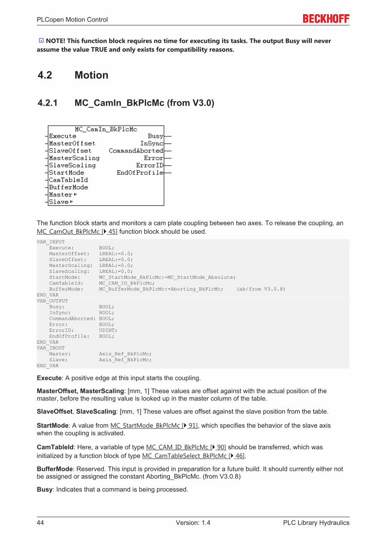
PLCopen Motion Control
PLC Library Hydraulics44 Version: 1.4
NOTE! This function block requires no time for executing its tasks. The output Busy will neverassume the value TRUE and only exists for compatibility reasons.
4.2 Motion
4.2.1 MC_CamIn_BkPlcMc (from V3.0)
The function block starts and monitors a cam plate coupling between two axes. To release the coupling, anMC_CamOut_BkPlcMc [} 45] function block should be used.VAR_INPUT Execute: BOOL; MasterOffset: LREAL:=0.0; SlaveOffset: LREAL:=0.0; MasterScaling: LREAL:=0.0; SlaveScaling: LREAL:=0.0; StartMode: MC_StartMode_BkPlcMc:=MC_StartMode_Absolute; CamTableId: MC_CAM_ID_BkPlcMc; BufferMode: MC_BufferMode_BkPlcMc:=Aborting_BkPlcMc; (ab/from V3.0.8)END_VARVAR_OUTPUT Busy: BOOL; InSync: BOOL; CommandAborted: BOOL; Error: BOOL; ErrorID: UDINT; EndOfProfile: BOOL;END_VARVAR_INOUT Master: Axis_Ref_BkPlcMc; Slave: Axis_Ref_BkPlcMc;END_VAR
Execute: A positive edge at this input starts the coupling.
MasterOffset, MasterScaling: [mm, 1] These values are offset against with the actual position of themaster, before the resulting value is looked up in the master column of the table.
SlaveOffset, SlaveScaling: [mm, 1] These values are offset against the slave position from the table.
StartMode: A value from MC_StartMode_BkPlcMc [} 91], which specifies the behavior of the slave axiswhen the coupling is activated.
CamTableId: Here, a variable of type MC_CAM_ID_BkPlcMc [} 90] should be transferred, which wasinitialized by a function block of type MC_CamTableSelect_BkPlcMc [} 46].
BufferMode: Reserved. This input is provided in preparation for a future build. It should currently either notbe assigned or assigned the constant Aborting_BkPlcMc. (from V3.0.8)
Busy: Indicates that a command is being processed.
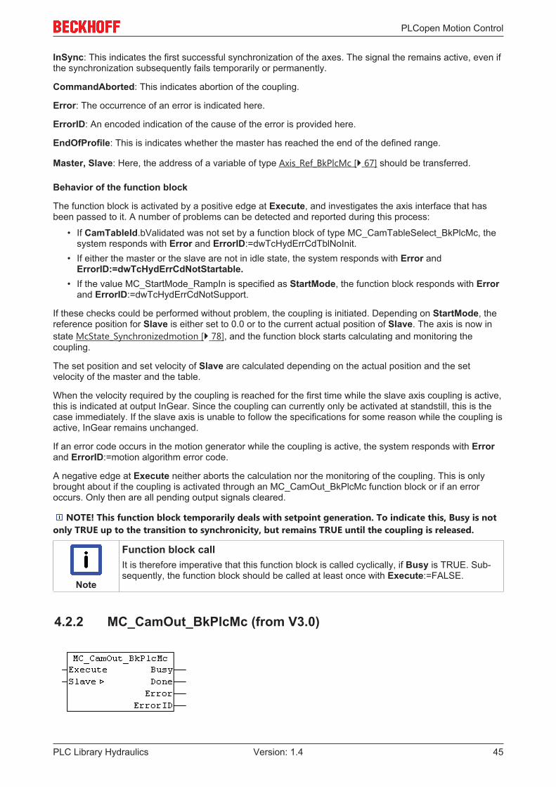
PLCopen Motion Control
PLC Library Hydraulics 45Version: 1.4
InSync: This indicates the first successful synchronization of the axes. The signal the remains active, even ifthe synchronization subsequently fails temporarily or permanently.
CommandAborted: This indicates abortion of the coupling.
Error: The occurrence of an error is indicated here.
ErrorID: An encoded indication of the cause of the error is provided here.
EndOfProfile: This is indicates whether the master has reached the end of the defined range.
Master, Slave: Here, the address of a variable of type Axis_Ref_BkPlcMc [} 67] should be transferred.
Behavior of the function block
The function block is activated by a positive edge at Execute, and investigates the axis interface that hasbeen passed to it. A number of problems can be detected and reported during this process:
• If CamTableId.bValidated was not set by a function block of type MC_CamTableSelect_BkPlcMc, thesystem responds with Error and ErrorID:=dwTcHydErrCdTblNoInit.
• If either the master or the slave are not in idle state, the system responds with Error andErrorID:=dwTcHydErrCdNotStartable.
• If the value MC_StartMode_RampIn is specified as StartMode, the function block responds with Errorand ErrorID:=dwTcHydErrCdNotSupport.
If these checks could be performed without problem, the coupling is initiated. Depending on StartMode, thereference position for Slave is either set to 0.0 or to the current actual position of Slave. The axis is now instate McState_Synchronizedmotion [} 78], and the function block starts calculating and monitoring thecoupling.
The set position and set velocity of Slave are calculated depending on the actual position and the setvelocity of the master and the table.
When the velocity required by the coupling is reached for the first time while the slave axis coupling is active,this is indicated at output InGear. Since the coupling can currently only be activated at standstill, this is thecase immediately. If the slave axis is unable to follow the specifications for some reason while the coupling isactive, InGear remains unchanged.
If an error code occurs in the motion generator while the coupling is active, the system responds with Errorand ErrorID:=motion algorithm error code.
A negative edge at Execute neither aborts the calculation nor the monitoring of the coupling. This is onlybrought about if the coupling is activated through an MC_CamOut_BkPlcMc function block or if an erroroccurs. Only then are all pending output signals cleared.
NOTE! This function block temporarily deals with setpoint generation. To indicate this, Busy is notonly TRUE up to the transition to synchronicity, but remains TRUE until the coupling is released.
Note
Function block callIt is therefore imperative that this function block is called cyclically, if Busy is TRUE. Sub-sequently, the function block should be called at least once with Execute:=FALSE.
4.2.2 MC_CamOut_BkPlcMc (from V3.0)
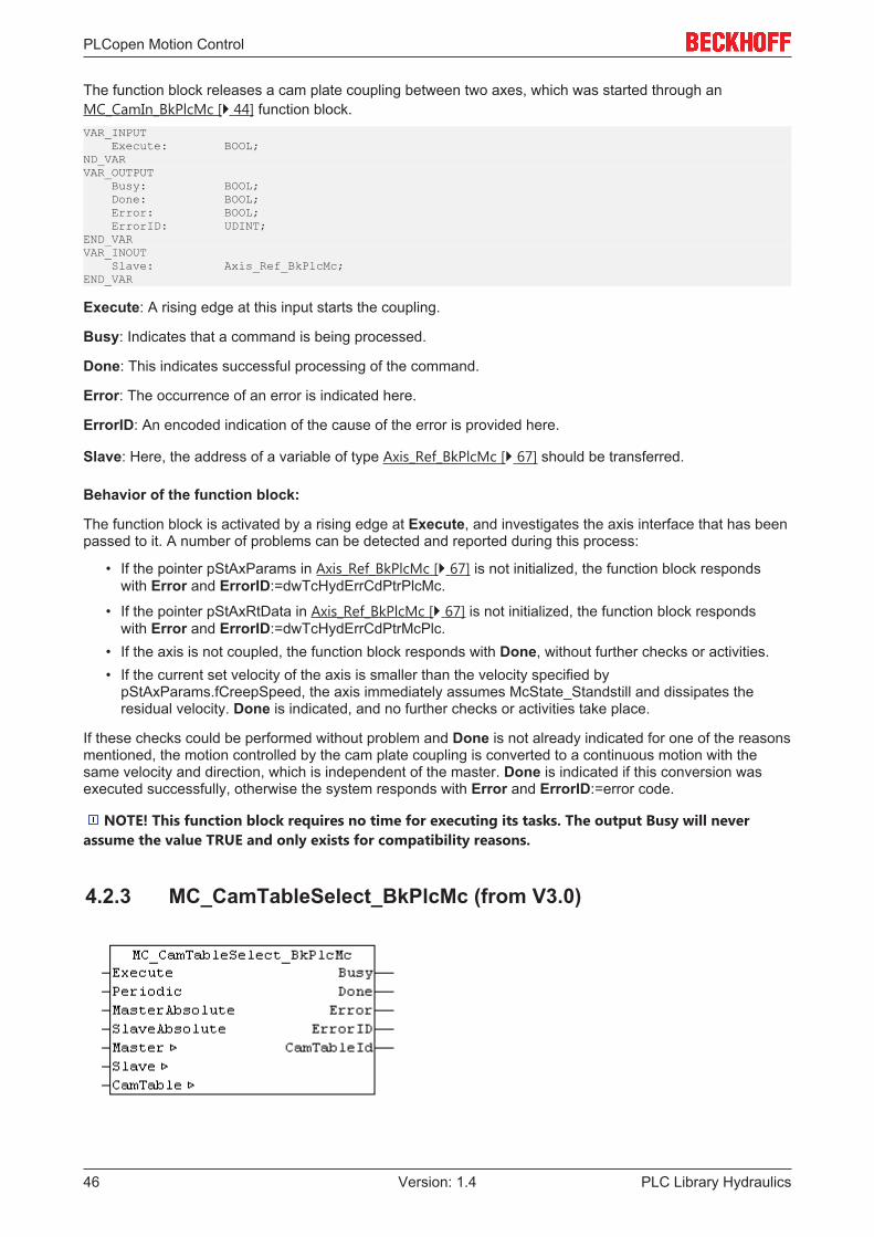
PLCopen Motion Control
PLC Library Hydraulics46 Version: 1.4
The function block releases a cam plate coupling between two axes, which was started through anMC_CamIn_BkPlcMc [} 44] function block.VAR_INPUT Execute: BOOL;ND_VARVAR_OUTPUT Busy: BOOL; Done: BOOL; Error: BOOL; ErrorID: UDINT;END_VARVAR_INOUT Slave: Axis_Ref_BkPlcMc;END_VAR
Execute: A rising edge at this input starts the coupling.
Busy: Indicates that a command is being processed.
Done: This indicates successful processing of the command.
Error: The occurrence of an error is indicated here.
ErrorID: An encoded indication of the cause of the error is provided here.
Slave: Here, the address of a variable of type Axis_Ref_BkPlcMc [} 67] should be transferred.
Behavior of the function block:
The function block is activated by a rising edge at Execute, and investigates the axis interface that has beenpassed to it. A number of problems can be detected and reported during this process:
• If the pointer pStAxParams in Axis_Ref_BkPlcMc [} 67] is not initialized, the function block respondswith Error and ErrorID:=dwTcHydErrCdPtrPlcMc.
• If the pointer pStAxRtData in Axis_Ref_BkPlcMc [} 67] is not initialized, the function block respondswith Error and ErrorID:=dwTcHydErrCdPtrMcPlc.
• If the axis is not coupled, the function block responds with Done, without further checks or activities.• If the current set velocity of the axis is smaller than the velocity specified by
pStAxParams.fCreepSpeed, the axis immediately assumes McState_Standstill and dissipates theresidual velocity. Done is indicated, and no further checks or activities take place.
If these checks could be performed without problem and Done is not already indicated for one of the reasonsmentioned, the motion controlled by the cam plate coupling is converted to a continuous motion with thesame velocity and direction, which is independent of the master. Done is indicated if this conversion wasexecuted successfully, otherwise the system responds with Error and ErrorID:=error code.
NOTE! This function block requires no time for executing its tasks. The output Busy will neverassume the value TRUE and only exists for compatibility reasons.
4.2.3 MC_CamTableSelect_BkPlcMc (from V3.0)
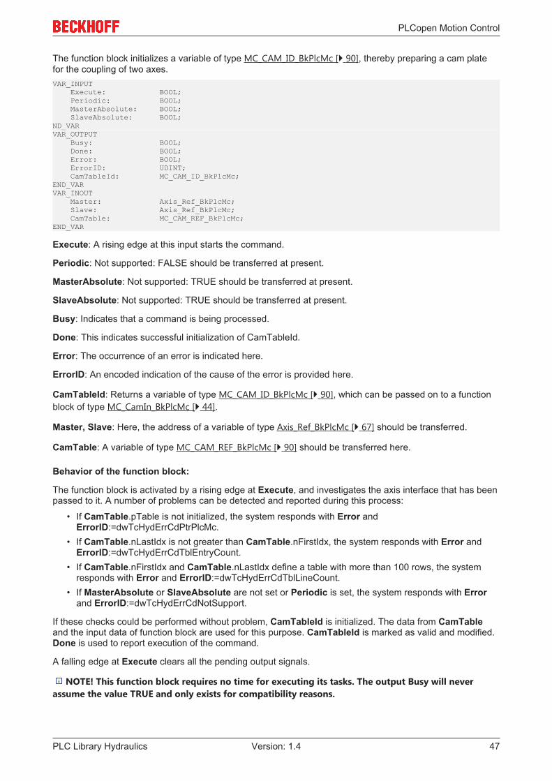
PLCopen Motion Control
PLC Library Hydraulics 47Version: 1.4
The function block initializes a variable of type MC_CAM_ID_BkPlcMc [} 90], thereby preparing a cam platefor the coupling of two axes.VAR_INPUT Execute: BOOL; Periodic: BOOL; MasterAbsolute: BOOL; SlaveAbsolute: BOOL;ND_VARVAR_OUTPUT Busy: BOOL; Done: BOOL; Error: BOOL; ErrorID: UDINT; CamTableId: MC_CAM_ID_BkPlcMc;END_VARVAR_INOUT Master: Axis_Ref_BkPlcMc; Slave: Axis_Ref_BkPlcMc; CamTable: MC_CAM_REF_BkPlcMc;END_VAR
Execute: A rising edge at this input starts the command.
Periodic: Not supported: FALSE should be transferred at present.
MasterAbsolute: Not supported: TRUE should be transferred at present.
SlaveAbsolute: Not supported: TRUE should be transferred at present.
Busy: Indicates that a command is being processed.
Done: This indicates successful initialization of CamTableId.
Error: The occurrence of an error is indicated here.
ErrorID: An encoded indication of the cause of the error is provided here.
CamTableId: Returns a variable of type MC_CAM_ID_BkPlcMc [} 90], which can be passed on to a functionblock of type MC_CamIn_BkPlcMc [} 44].
Master, Slave: Here, the address of a variable of type Axis_Ref_BkPlcMc [} 67] should be transferred.
CamTable: A variable of type MC_CAM_REF_BkPlcMc [} 90] should be transferred here.
Behavior of the function block:
The function block is activated by a rising edge at Execute, and investigates the axis interface that has beenpassed to it. A number of problems can be detected and reported during this process:
• If CamTable.pTable is not initialized, the system responds with Error andErrorID:=dwTcHydErrCdPtrPlcMc.
• If CamTable.nLastIdx is not greater than CamTable.nFirstIdx, the system responds with Error andErrorID:=dwTcHydErrCdTblEntryCount.
• If CamTable.nFirstIdx and CamTable.nLastIdx define a table with more than 100 rows, the systemresponds with Error and ErrorID:=dwTcHydErrCdTblLineCount.
• If MasterAbsolute or SlaveAbsolute are not set or Periodic is set, the system responds with Errorand ErrorID:=dwTcHydErrCdNotSupport.
If these checks could be performed without problem, CamTableId is initialized. The data from CamTableand the input data of function block are used for this purpose. CamTableId is marked as valid and modified.Done is used to report execution of the command.
A falling edge at Execute clears all the pending output signals.
NOTE! This function block requires no time for executing its tasks. The output Busy will neverassume the value TRUE and only exists for compatibility reasons.
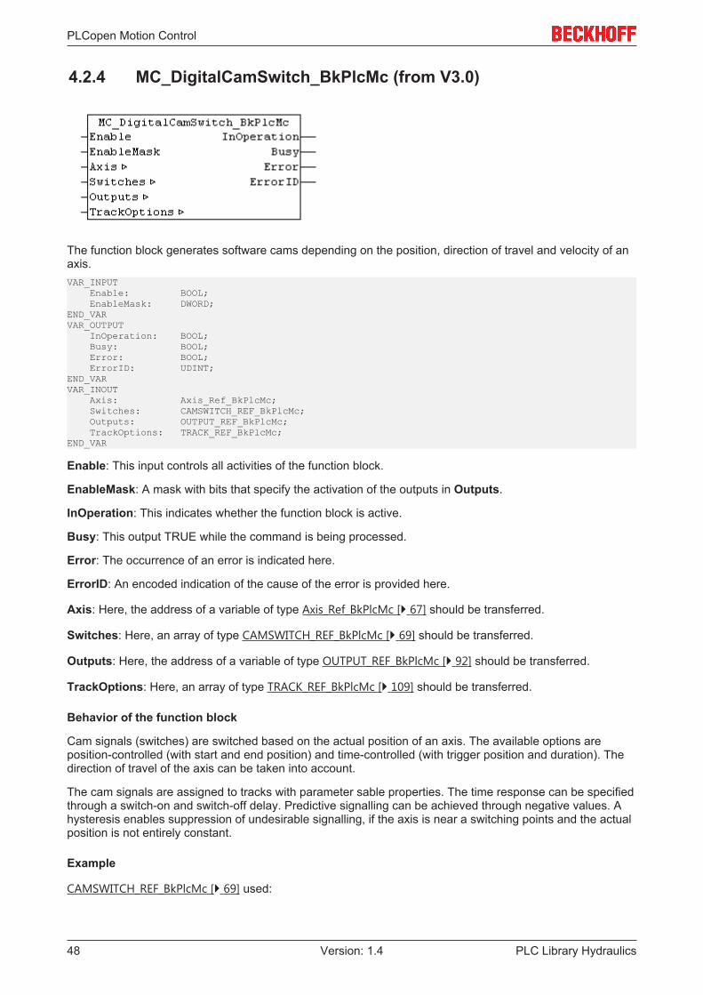
PLCopen Motion Control
PLC Library Hydraulics48 Version: 1.4
4.2.4 MC_DigitalCamSwitch_BkPlcMc (from V3.0)
The function block generates software cams depending on the position, direction of travel and velocity of anaxis.VAR_INPUT Enable: BOOL; EnableMask: DWORD;END_VARVAR_OUTPUT InOperation: BOOL; Busy: BOOL; Error: BOOL; ErrorID: UDINT;END_VARVAR_INOUT Axis: Axis_Ref_BkPlcMc; Switches: CAMSWITCH_REF_BkPlcMc; Outputs: OUTPUT_REF_BkPlcMc; TrackOptions: TRACK_REF_BkPlcMc;END_VAR
Enable: This input controls all activities of the function block.
EnableMask: A mask with bits that specify the activation of the outputs in Outputs.
InOperation: This indicates whether the function block is active.
Busy: This output TRUE while the command is being processed.
Error: The occurrence of an error is indicated here.
ErrorID: An encoded indication of the cause of the error is provided here.
Axis: Here, the address of a variable of type Axis_Ref_BkPlcMc [} 67] should be transferred.
Switches: Here, an array of type CAMSWITCH_REF_BkPlcMc [} 69] should be transferred.
Outputs: Here, the address of a variable of type OUTPUT_REF_BkPlcMc [} 92] should be transferred.
TrackOptions: Here, an array of type TRACK_REF_BkPlcMc [} 109] should be transferred.
Behavior of the function block
Cam signals (switches) are switched based on the actual position of an axis. The available options areposition-controlled (with start and end position) and time-controlled (with trigger position and duration). Thedirection of travel of the axis can be taken into account.
The cam signals are assigned to tracks with parameter sable properties. The time response can be specifiedthrough a switch-on and switch-off delay. Predictive signalling can be achieved through negative values. Ahysteresis enables suppression of undesirable signalling, if the axis is near a switching points and the actualposition is not entirely constant.
Example
CAMSWITCH_REF_BkPlcMc [} 69] used:

PLCopen Motion Control
PLC Library Hydraulics 49Version: 1.4
Parameter Switch[1] Switch[2] Switch[3] Switch[4] ... Switch[n]TrackNumber 1 1 1 2FirstOnPosition
2000.0 2500.0 -1000.0 3000.0
LastOnPosition
3000.0 3000.0 1000.0
AxisDirection 1 2 0 0CamSwitchMode
0 0 0 1
Duration 1.35.....
TRACK_REF_BkPlcMc [} 109] used:
Parameter Track[1] Track[2] ... Track[n]OnCompensation -0.125 0.0OffCompensation 0.250 0.0Hysteresis 0.0 0.0
Signal curves during axis motion from 0.0 to 5000.0 and back:
The following diagram shows the signal curves over the position. For positive direction of travel the signalsare shown normally (upwards), for negative direction of travel they are shown negative, i.e. 'downwards'. Thevertical cursor lines indicate the positions 1000 and 3000 mm.

PLCopen Motion Control
PLC Library Hydraulics50 Version: 1.4
4.2.5 MC_EmergencyStop_BkPlcMc (from V3.0.5)
The function block cancels a current axis motion and monitors the emergency stop operation.VAR_INPUT Execute: BOOL; RampTime: LREAL; (ab/from V3.0.5)END_VARVAR_OUTPUT Busy: BOOL; Done: BOOL; Error: BOOL; ErrorID: UDINT; Active: BOOL; CommandAborted: BOOL;END_VARVAR_INOUT Axis: Axis_Ref_BkPlcMc;END_VAR
Execute: A positive edge at this input ends a movement being carried out by the axis.

PLCopen Motion Control
PLC Library Hydraulics 51Version: 1.4
RampTime: [s] The required stopping time.
Busy: Indicates that a command is being processed.
Done: This indicates successful processing of the operation.
Error: The occurrence of an error is indicated here.
ErrorID: An encoded indication of the cause of the error is provided here.
Active: Indicates that a command is being processed.
CommandAborted: Indicates that processing of this command was canceled by another command.
Axis: Here, the address of a variable of type Axis_Ref_BkPlcMc [} 67] should be transferred.
Behavior of the function block
The function block is activated by a positive edge at Execute, and investigates the axis interface that hasbeen passed to it. A number of problems can be detected and reported during this process:
• The stop can only be executed if the axis is actively carrying out a movement. If it is stationary, thefunction block immediately asserts the Done signal.
• If the axis is already in a fault state, or if it is in the process of carrying out a stop operation, it respondswith Error and ErrorID:=dwTcHydErrCdNotReady.
• If the axis is in a state, in which it is controlled by a coupling with another axis or a comparablemechanism, it responds with Error and ErrorID:=dwTcHydErrCdNotReady.
The Stop operation begins if these checks can be carried out without problems. RampTime is used tocalculate a deceleration, taking into account the reference speed. MaxJerk is used if a jerk-limiting controlvalue generator is selected. If no value is specified for RampTime, which is recognizably greater than 0, theaxis parameter fEmergencyRamp is used.
An MC_Stop_BkPlcMc [} 66] function block is used internally for slowing down the axis. Once the controlvalue output is reduced to 0, all control or regulating voltage outputs are suppressed, as long as Execute isset to TRUE.
4.2.6 MC_GearIn_BkPlcMc (from V3.0)
The function block starts and monitors a coupling between two axes. To release the coupling, anMC_GearOut_BkPlcMc [} 55] function block should be used.VAR_INPUT Execute: BOOL; RatioNumerator: INT; RatioDenominator: INT; Acceleration: LREAL; Deceleration: LREAL; Jerk: LREAL; (ab/from V3.0.5) BufferMode: MC_BufferMode_BkPlcMc:=Aborting_BkPlcMc; (ab/from V3.0.8)END_VAR

PLCopen Motion Control
PLC Library Hydraulics52 Version: 1.4
VAR_OUTPUT Busy: BOOL; InGear: BOOL; CommandAborted: BOOL; Error: BOOL; ErrorID: UDINT; Active: BOOL;END_VARVAR_INOUT Master: Axis_Ref_BkPlcMc; Slave: Axis_Ref_BkPlcMc;END_VAR
Execute: A positive edge at this input starts the coupling.
RatioNumerator, RatioDenominator: [1, 1] These parameters describe the coupling factor in the form of agear unit.
Acceleration: [mm/s2] The acceleration permitted for the synchronization in actual value units of the axis persquare second.
Deceleration: [mm/s2] The deceleration permitted for the synchronization in actual value units of the axis persquare second.
Jerk: [mm/s3] The jerk to be applied.
BufferMode: Reserved. This input is provided in preparation for a future build. It should currently either notbe assigned or assigned the constant Aborting_BkPlcMc. (from V3.0.8)
Busy: Indicates that a command is being processed.
InGear: This indicates the first successful synchronization of the axes. The signal the remains active, even ifthe synchronization subsequently fails temporarily or permanently.
CommandAborted: This indicates abortion of the coupling.
Error: The occurrence of an error is indicated here.
ErrorID: An encoded indication of the cause of the error is provided here.
Active: Indicates that a command is being processed.
Master, Slave: Here, the address of a variable of type Axis_Ref_BkPlcMc [} 67] should be transferred.
Behavior of the function block
The function block is activated by a positive edge at Execute, and investigates the axis interface that hasbeen passed to it. A number of problems can be detected and reported during this process:
• Next, the system checks whether RatioDenominator is 0. In this case the function block will react byasserting Error with ErrorID:=dwTcHydErrCdIllegalGearFactor.
• Currently, the coupling can only be activated if both the master and the slave are at standstill.Otherwise the system responds with Error and ErrorID:=dwTcHydErrCdNotStartable.
• If the axis is already in a fault state, or if it is in the process of carrying out a stop operation, it respondswith Error and ErrorID:=dwTcHydErrCdNotReady.
• If the movement algorithm is already indicating an error code, the function block responds with Errorand ErrorID:= the movement algorithm's error code.
If these checks could be performed without problem, the coupling is initiated. The axis is now in stateMcState_Synchronizedmotion [} 78], and the function block starts monitoring the coupling.
When the velocity required by the coupling is reached for the first time while the slave axis coupling is active,this is indicated at output InGear. Since the coupling can currently only be activated at standstill, this is thecase immediately. If the slave axis is unable to follow the specifications for some reason while the coupling isactive, InGear remains unchanged.
If an error code occurs in the motion generator while the coupling is active, the system responds with Errorand ErrorID:=motion algorithm error code.

PLCopen Motion Control
PLC Library Hydraulics 53Version: 1.4
A negative edge at Execute clears all the pending output signals. If Execute is set to FALSE while thecoupling is still active, the existing coupling remains unaffected and active.
NOTE! The output Active is currently identical to the output Busy.
4.2.7 MC_GearInPos_BkPlcMc (from V3.0.33)
The function block starts and monitors an on-the-fly coupling between two axes. To release the coupling, anMC_GearOut_BkPlcMc [} 55] function block should be used.VAR_INPUT Execute: BOOL; RatioNumerator: INT; RatioDenominator: INT; MasterSyncPosition: LREAL; SlaveSyncPosition: LREAL; SyncMode: INT; MasterStartDistance: LREAL; Acceleration: LREAL; Deceleration: LREAL; Jerk: LREAL; (ab/from V3.0.5) BufferMode: MC_BufferMode_BkPlcMc:=Aborting_BkPlcMc;END_VARVAR_OUTPUT StartSync: BOOL; InSync: BOOL; Busy: BOOL; Active: BOOL; CommandAborted: BOOL; Error: BOOL; ErrorID: UDINT;END_VARVAR_INOUT Master: Axis_Ref_BkPlcMc; Slave: Axis_Ref_BkPlcMc;END_VAR
Execute: A positive edge at this input starts the coupling.
RatioNumerator, RatioDenominator: [1, 1] These parameters describe the coupling factor in the form of agear unit.
MasterSyncPosition: [mm] The coupling is fully active from this master position.
SlaveSyncPosition: [mm] The coupling is fully active from this slave position.
SyncMode: Currently not supported.
MasterStartDistance: [mm] This is the master distance over which the coupling is established.
PLCopen Motion Control
PLC Library Hydraulics54 Version: 1.4
Acceleration: [mm/s2] The acceleration permitted for the synchronization in actual value units of the axis persquare second.
Deceleration: [mm/s2] The deceleration permitted for the synchronization in actual value units of the axis persquare second.
Jerk: [mm/s3] The jerk to be applied.
BufferMode: Reserved. This input is provided in preparation for a future build. It should currently either notbe assigned or assigned the constant Aborting_BkPlcMc. (from V3.0.8)
StartSync: Indicates the transition phase between idle state and fully active coupling.
InSync: This indicates the first successful synchronization of the axes. The signal the remains active, even ifthe synchronization subsequently fails temporarily or permanently.
Busy: Indicates that a command is being processed.
Active: Indicates that a command is being processed.
CommandAborted: This indicates abortion of the coupling.
Error: The occurrence of an error is indicated here.
ErrorID: An encoded indication of the cause of the error is provided here.
Master, Slave: Here, the address of a variable of type Axis_Ref_BkPlcMc [} 67] should be transferred.
Behavior of the function block
The function block is activated by a positive edge at Execute, and investigates the axis interface that hasbeen passed to it. A number of problems can be detected and reported during this process:
• Next, the system checks whether RatioDenominator is 0. In this case the function block will react byasserting Error with ErrorID:=dwTcHydErrCdIllegalGearFactor.
• If RatioDenominator is less than 0, the system responds with Error andErrorID:=dwTcHydErrCdNotSupport.
• The coupling can only be activated if the slave is at standstill. Otherwise the system responds withError and ErrorID:=dwTcHydErrCdNotStartable.
• If the absolute value of the MasterStartDistance is too small, the system responds with Error andErrorID:=dwTcHydErrCdCannotSynchronize.
• If the actual position of the master is not between MasterSyncPosition and the end of thesynchronization distance specified by MasterStartDistance, the system responds with Error andErrorID:=dwTcHydErrCdCannotSynchronize.
If these checks could be performed without problem, the coupling is initiated. The slave axis initiallycontinues to be in state McState_Standstill [} 78]. Only when the master axis reaches the start of thesynchronization distance for the first time does the slave axis report McState_Synchronizedmotion [} 78]and indicate StartSync, and the function block starts monitoring the coupling. As soon as the axis reachesthe end the synchronization distance for the first time, the slave axis indicates InSync. Should the masteraxis later pass the start of the synchronization distance backwards, the coupling is not released.
If an error code occurs in the motion generator while the coupling is active, the system responds with Errorand ErrorID:=motion algorithm error code.
A negative edge at Execute clears all the pending output signals. If Execute is set to FALSE while thecoupling is still active, the existing coupling remains unaffected and active.
An example is available under #103 [} 255].
CAUTION! The function block does not support the functionality of TwinCAT NC.
NOTE! The output Active is currently identical to the output Busy.

PLCopen Motion Control
PLC Library Hydraulics 55Version: 1.4
4.2.8 MC_GearOut_BkPlcMc (from V3.0)
The function block releases a coupling between two axes. This coupling must have been established with anMC_GearIn_BkPlcMc [} 51] or an MC_GearInPos_BkPlcMc [} 53] function block.VAR_INPUT Execute: BOOL;END_VARVAR_OUTPUT Busy: BOOL; Done: BOOL; Error: BOOL; ErrorID: UDINT;END_VARVAR_INOUT Slave: Axis_Ref_BkPlcMc;END_VAR
Execute: A rising edge at this input releases the coupling.
Busy: Indicates that a command is being processed.
Done: Successful processing of the movement is indicated here.
Error: The occurrence of an error is indicated here.
ErrorID: An encoded indication of the cause of the error is provided here.
Slave: Here, the address of a variable of type Axis_Ref_BkPlcMc [} 67] should be transferred.
Behavior of the function block:
The function block is activated by a rising edge at Execute, and investigates the axis interface that has beenpassed to it. A number of problems can be detected and reported during this process:
• If the axis is not operated in a gear coupling, the function block immediately indicates Done and omitsall further checks or activities.
• If the current set velocity of the axis is smaller than the velocity specified bypStAxParams.fCreepSpeed, the axis immediately assumes McState_Standstill and dissipates theresidual velocity. Done is indicated, and no further checks or activities take place.
If these checks could be performed without problem and Done is not already indicated for one of the reasonsmentioned, the motion controlled by the gear coupling is converted to a continuous motion with the samevelocity and direction, which is independent of the master. Done is indicated if this conversion was executedsuccessfully, otherwise the system responds with Error and ErrorID:=error code.

PLCopen Motion Control
PLC Library Hydraulics56 Version: 1.4
4.2.9 MC_Halt_BkPlcMc (from V3.0)
The function block cancels a current axis motion and monitors the stop operation.
NOTE! The stop operation initiated by this function block can be interrupted by other functionblocks. An MC_Stop_BkPlcMc function block can be used to prevent the axis from restarting during astop operation.VAR_INPUT Execute: BOOL; Deceleration: LREAL; (ab/from V3.0.5) Jerk: LREAL; (ab/from V3.0.5) RampTime: LREAL; (ab/from V3.0.5) BufferMode: MC_BufferMode_BkPlcMc:=Aborting_BkPlcMc; (ab/from V3.0.8)END_VARVAR_OUTPUT Busy: BOOL; Done: BOOL; Error: BOOL; ErrorID: UDINT; Active: BOOL; CommandAborted: BOOL;END_VARVAR_INOUT Axis: Axis_Ref_BkPlcMc;END_VAR
Execute: A positive edge at this input ends a movement being carried out by the axis.
Deceleration: [mm/s2] The deceleration to be applied.
Jerk: [mm/s3] The jerk to be applied.
RampTime: [s] The required stopping time.
BufferMode: Reserved. This input is provided in preparation for a future build. It should currently either notbe assigned or assigned the constant Aborting_BkPlcMc. (from V3.0.8)
Busy: Indicates that a command is being processed.
Done: This indicates successful processing of the operation.
Error: The occurrence of an error is indicated here.
ErrorID: An encoded indication of the cause of the error is provided here.
Active: Indicates that a command is being processed.
CommandAborted: Indicates that processing of this command was canceled by another command.
Axis: Here, the address of a variable of type Axis_Ref_BkPlcMc [} 67] should be transferred.
Behavior of the function block
The behavior of the function block is identical to that of the MC_Stop_BkPlcMc [} 66]() function block. Theonly difference is that processing of the command can be canceled by other function blocks.

PLCopen Motion Control
PLC Library Hydraulics 57Version: 1.4
4.2.10 MC_Home_BkPlcMc (from V3.0)
This function block starts and monitors the homing of an axis.VAR_INPUT Execute: BOOL; Position: LREAL; HomingMode: MC_HomingMode_BkPlcMc; CalibrationCam: BOOL; BufferMode: MC_BufferMode_BkPlcMc:=Aborting_BkPlcMc; (ab/from V3.0.8)END_VARVAR_OUTPUT Busy: BOOL; Done: BOOL; CommandAborted: BOOL; Error: BOOL; ErrorID: UDINT;END_VARVAR_INOUT Axis: Axis_Ref_BkPlcMc;END_VAR
Execute: The homing is initiated by a positive edge at this input.
Position: [mm] The reference position.
HomingMode: Specifies the method [} 91] to be used.
CalibrationCam: This can be used for direct transfer of the referencing index (cam).
BufferMode: Reserved. This input is provided in preparation for a future build. It should currently either notbe assigned or assigned the constant Aborting_BkPlcMc. (from V3.0.8)
Busy: Indicates that a command is being processed.
Done: Successful processing of the homing is indicated here.
CommandAborted: Abortion of homing is indicated here.
Error: The occurrence of an error is indicated here.
ErrorID: An encoded indication of the cause of the error is provided here.
Axis: Here, the address of a variable of type Axis_Ref_BkPlcMc [} 67] should be transferred.
Behavior of the function block
The function block is activated by a positive edge at Execute, and investigates the axis interface that hasbeen passed to it. A number of problems can be detected and reported during this process:
• Homing can only be started from a stationary condition without errors. If that is not the case, thefunction block will react by asserting Error with ErrorID:=dwTcHydErrCdNotStartable or with the errorcode that is passed to it.
• If the axis is already in a fault state, or if it is in the process of carrying out a stop operation, it respondswith Error and ErrorID:=dwTcHydErrCdNotReady.
• If one of the velocities stated in the axis parameters is too small (less than 1% of the reference velocity)the function block responds with Error and ErrorID:=dwTcHydErrCdSetVelo.

PLCopen Motion Control
PLC Library Hydraulics58 Version: 1.4
Homing begins if these checks are carried out without problems. The exact sequence is specified byHomingMode [} 91]. If the movement algorithm reports an error code while homing is being executed, thefunction block responds with Error and ErrorID:=the movement algorithm's error code. If completion ofhoming is prevented by the activity of another function block, the function block responds withCommandAborted. Successful completion of homing is reported with Done.
A negative edge at Execute clears all the pending output signals. If, while homing is still active, Execute isset to FALSE, execution of homing that had started continues unaffected. The signals provided at the end ofthe movement (Error, ErrorID, CommandAborted, Done) are made available for one cycle.
CAUTION! fEnc_DefaultHomePosition in pStAxParams is provided for circumstances in which theapplication does not itself specify a reference position and a value saved with the machine data is tobe loaded for use instead. If different values are required, depending on the situation, use should bemade of fCustomerData[] in pStAxParams.
If iTcMc_EncoderSim is set as encoder type, the mode MC_Direct_BkPlcMc takes effect, irrespective ofHomingMode and Axis_Ref_BkPlcMc [} 67].stAxParams.nEnc_HomingType.
MC_DefaultHomingMode_BkPlcMc
The referencing method is not specified by the application, but through Axis_Ref_BkPlcMc[} 67].stAxParams.nEnc_HomingType. The following rules apply:
nEnc_HomingType MC_HomingMode_BkPlcMciTcMc_HomingOnBlock MC_Block_BkPlcMciTcMc_HomingOnIndex MC_AbsSwitch_BkPlcMciTcMc_HomingOnSync MC_RefPulse_BkPlcMciTcMc_HomingOnExec MC_Direct_BkPlcMc
MC_AbsSwitch_BkPlcMc
The axis is moved with Axis_Ref_BkPlcMc [} 67].stAxParams.fEnc_RefIndexVelo in the direction specifiedby bEnc_RefIndexPositive. The axis stops if CalibrationCam becomes TRUE or if the reference cam (bit 5,dwTcHydDcDwRefIndex) is detected in Axis_Ref_BkPlcMc [} 67].stAxRtData.nDeCtrlDWord. The axis isthen moved with fEnc_RefSyncVelo in the direction specified by bEnc_RefSyncPositive, until the referencecam is exited. The actual value for the axis is set to the value of the reference position.
MC_LimitSwitch_BkPlcMc
Not currently supported.
MC_RefPulse_BkPlcMc
The axis is moved with Axis_Ref_BkPlcMc [} 67].stAxParams.fEnc_RefIndexVelo in the direction specifiedby bEnc_RefIndexPositive. The axis stops if CalibrationCam becomes TRUE or if the reference cam (bit 5,dwTcHydDcDwRefIndex) is detected in Axis_Ref_BkPlcMc [} 67].stAxRtData.nDeCtrlDWord. The axis isthen moved with fEnc_RefSyncVelo in the direction specified by bEnc_RefSyncPositive, until the referencecam is exited. The encoder's hardware latch is then activated, and the axis is moved on until the latchbecomes valid. After the axis has stopped, the actual value for the axis is set to a value that is calculatedfrom the reference position and from the distance covered since the encoder's sync pulse was detected.
MC_Direct_BkPlcMc
The actual value of the axis is immediately set to the value of the reference position.
MC_Absolute_BkPlcMc
Not currently supported.

PLCopen Motion Control
PLC Library Hydraulics 59Version: 1.4
MC_Block_BkPlcMc
The axis is moved with Axis_Ref_BkPlcMc [} 67].stAxParams.fEnc_RefIndexVelo in the direction specifiedby bEnc_RefIndexPositive. If no movement is detected over a period of 2 seconds, the fixed stop (block) isconsidered to have been reached. The actual value for the axis is set to the value of the reference position.
From version 3.0.41 of 12 October 2017 it is possible to change the time period for the function blockdetection. See ST_TcHydAxRtData [} 99].fBlockDetectDelay.
MC_FlyingSwitch_BkPlcMc
Not currently supported.
MC_FlyingRefPulse_BkPlcMc
Not currently supported.
4.2.11 MC_ImediateStop_BkPlcMc (from V3.0.5)
The function block cancels a current axis motion.VAR_INPUT Execute: BOOL;END_VARVAR_OUTPUT Busy: BOOL; Done: BOOL; Error: BOOL; ErrorID: UDINT; Active: BOOL; CommandAborted: BOOL;END_VARVAR_INOUT Axis: Axis_Ref_BkPlcMc;END_VAR
Execute: A rising edge at this input ends a movement being carried out by the axis.
Busy: Indicates that a command is being processed.
Done: This indicates successful processing of the operation.
Error: The occurrence of an error is indicated here.
ErrorID: An encoded indication of the cause of the error is provided here.
Active: Indicates that a command is being processed.
CommandAborted: Indicates that processing of this command was cancelled by another command.
Axis: Here, the address of a variable of type Axis_Ref_BkPlcMc [} 67] should be transferred.
Behavior of the function block:
The function block is activated by a rising edge at Execute, and investigates the axis interface that has beenpassed to it. A number of problems can be detected and reported during this process:

PLCopen Motion Control
PLC Library Hydraulics60 Version: 1.4
• The stop can only be executed if the axis is actively carrying out a movement. If it is stationary, thefunction block immediately asserts the Done signal.
• If the axis is already in a fault state, or if it is in the process of carrying out a stop operation, it respondswith Error and ErrorID:=dwTcHydErrCdNotReady.
• If the axis is in a state, in which it is controlled by a coupling with another axis or a comparablemechanism, it responds with Error and ErrorID:=dwTcHydErrCdNotReady.
The Stop operation begins if these checks can be carried out without problems. The control value of the axisis immediately set to 0, without any ramp. All outputs of control or regulation voltages are then suppressed,as long as Execute is set to TRUE.
4.2.12 MC_MoveAbsolute_BkPlcMc (from V3.0)
This function block starts and monitors the movement of an axis.VAR_INPUT Execute: BOOL; Position: LREAL; Velocity: LREAL; Acceleration: LREAL; Deceleration: LREAL; Jerk: LREAL; Direction: MC_Direction_BkPlcMc:=MC_Shortest_Way_BkPlcMc; (ab/from V3.0.8) BufferMode: MC_BufferMode_BkPlcMc:=Aborting_BkPlcMc; (ab/from V3.0.8)END_VARVAR_OUTPUT Busy: BOOL; Done: BOOL; CommandAborted: BOOL; Error: BOOL; ErrorID: UDINT;END_VARVAR_INOUT Axis: Axis_Ref_BkPlcMc;END_VAR
Execute: The movement is initiated by a positive edge at this input.
Position: [mm] The target position of the movement in actual value units of the axis.
Velocity: [mm/s] The required motion velocity in actual value units of the axis per second.
Acceleration: [mm/s2] The required acceleration in actual value units of the axis per square second. If thisparameter is 0.0, it is replaced by a default value from the axis parameters.
Deceleration: [mm/s2] The required deceleration in actual value units of the axis per square second. If thisparameter is 0.0, it is replaced by a default value from the axis parameters.
Jerk: [mm/s3] reserved.
Direction: Reserved. This input was only amended for compatibility reasons and either should not beassigned, or the constant MC_Shortest_Way_BkPlcMc should be assigned to it. (from V3.0.8)
PLCopen Motion Control
PLC Library Hydraulics 61Version: 1.4
BufferMode: Reserved. This input is provided in preparation for a future build. It should currently either notbe assigned or assigned the constant Aborting_BkPlcMc. (from V3.0.8)
Busy: Indicates that a command is being processed.
Done: Successful processing of the movement is indicated here.
CommandAborted: Abortion of the movement is indicated here.
Error: The occurrence of an error is indicated here.
ErrorID: An encoded indication of the cause of the error is provided here.
Axis: Here, the address of a variable of type Axis_Ref_BkPlcMc [} 67] should be transferred.
Behavior of the function block
The function block is activated by a positive edge at Execute, and investigates the axis interface that hasbeen passed to it. A number of problems can be detected and reported during this process:
• The possibility that Position is located behind an active software limit switch is checked next. In thiscase the function block will react by asserting Error with ErrorID:=dwTcHydErrCdSoftEnd.
• Depending on the movement algorithm specified in Axis.pStAxParams^.nProfile the axis may eitheronly be able to begin the movement initiated here when stationary, or may be able to begin fromanother movement that has not yet been completed. If it is unable at the present time to accept thisnew order, the function block responds with Error and ErrorID:=dwTcHydErrCdNotStartable.
• If the axis is already in a fault state, or if it is in the process of carrying out a stop operation, it respondswith Error and ErrorID:=dwTcHydErrCdNotReady.
• If Velocity is too small (less than 1% of the reference velocity) the function block reacts with Error andErrorID:=dwTcHydErrCdSetVelo.
• If Acceleration is too small (the Velocity cannot be reached within 100 seconds) the function blockreacts with Error and ErrorID:=dwTcHydErrCdAcc.
• If Deceleration is too small (the Velocity cannot be reached within 100 seconds) the function blockreacts with Error and ErrorID:=dwTcHydErrCdDec.
• If the movement algorithm is already indicating an error code, the function block responds with Errorand ErrorID:= the movement algorithm's error code.
The movement begins if these checks can be carried out without problems. This is done by limiting theparameters Position, Velocity, Acceleration and Deceleration to the maximum permissible values andpassing them to the movement algorithm. The axis is now in the McState_DiscreteMotion [} 78] state, andthe function block begins to monitor the movement.
If the movement algorithm reports an error code while the movement is being executed, the function blockresponds with Error and ErrorID:=the movement algorithm's error code. If completion of the movement isprevented by the activity of another function block, the function block responds with CommandAborted. Ifthe movement algorithm achieves the target conditions for the axis, the function block reacts with Done.
A negative edge at Execute clears all the pending output signals. If, while the movement is still active,Execute is set to FALSE, execution of the movement that had started continues unaffected. The signalsprovided at the end of the movement (Error, ErrorID, CommandAborted, Done) are made available for onecycle.
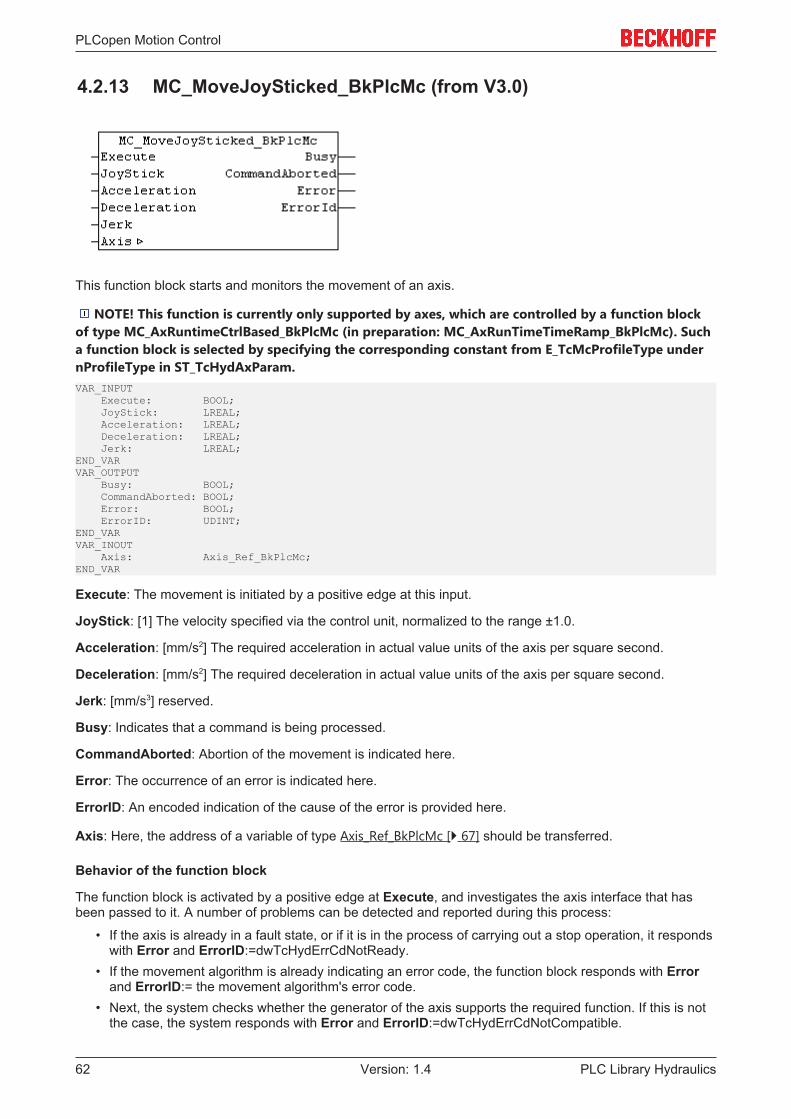
PLCopen Motion Control
PLC Library Hydraulics62 Version: 1.4
4.2.13 MC_MoveJoySticked_BkPlcMc (from V3.0)
This function block starts and monitors the movement of an axis.
NOTE! This function is currently only supported by axes, which are controlled by a function blockof type MC_AxRuntimeCtrlBased_BkPlcMc (in preparation: MC_AxRunTimeTimeRamp_BkPlcMc). Sucha function block is selected by specifying the corresponding constant from E_TcMcProfileType undernProfileType in ST_TcHydAxParam.VAR_INPUT Execute: BOOL; JoyStick: LREAL; Acceleration: LREAL; Deceleration: LREAL; Jerk: LREAL;END_VARVAR_OUTPUT Busy: BOOL; CommandAborted: BOOL; Error: BOOL; ErrorID: UDINT;END_VARVAR_INOUT Axis: Axis_Ref_BkPlcMc;END_VAR
Execute: The movement is initiated by a positive edge at this input.
JoyStick: [1] The velocity specified via the control unit, normalized to the range ±1.0.
Acceleration: [mm/s2] The required acceleration in actual value units of the axis per square second.
Deceleration: [mm/s2] The required deceleration in actual value units of the axis per square second.
Jerk: [mm/s3] reserved.
Busy: Indicates that a command is being processed.
CommandAborted: Abortion of the movement is indicated here.
Error: The occurrence of an error is indicated here.
ErrorID: An encoded indication of the cause of the error is provided here.
Axis: Here, the address of a variable of type Axis_Ref_BkPlcMc [} 67] should be transferred.
Behavior of the function block
The function block is activated by a positive edge at Execute, and investigates the axis interface that hasbeen passed to it. A number of problems can be detected and reported during this process:
• If the axis is already in a fault state, or if it is in the process of carrying out a stop operation, it respondswith Error and ErrorID:=dwTcHydErrCdNotReady.
• If the movement algorithm is already indicating an error code, the function block responds with Errorand ErrorID:= the movement algorithm's error code.
• Next, the system checks whether the generator of the axis supports the required function. If this is notthe case, the system responds with Error and ErrorID:=dwTcHydErrCdNotCompatible.

PLCopen Motion Control
PLC Library Hydraulics 63Version: 1.4
The movement begins if these checks can be carried out without problems. To this end the motion algorithmis set to state iTcHydStateExtGenerated and the axis to state McState_Synchronizedmotion. The axisvelocity is specified through JoyStick and ST_TcHydAxParam [} 93].fRefVelo. Changes in velocity areaccompanied by ramp limitation to ST_TcHydAxParam [} 93].fMaxAcc. If the axis moves towards an activesoftware limit switch, the velocity is limited, depending on the remaining distance, such that the limit switch isapproached correctly.
A falling edge at Execute offset puts motion algorithm in state iTcHydStateTcDecP or iTcHydStateTcDecMand the axis in state McState_Standstill. If the axis is in motion at this point in time, it is decelerated with astop ramp and assumes state iTcHydStateIdle.
4.2.14 MC_MoveRelative_BkPlcMc (from V3.0)
This function block starts and monitors the movement of an axis.VAR_INPUT Execute: BOOL; Distance: LREAL; Velocity: LREAL; Acceleration: LREAL; Deceleration: LREAL; Jerk: LREAL; BufferMode: MC_BufferMode_BkPlcMc:=Aborting_BkPlcMc; (ab/from V3.0.8)END_VARVAR_OUTPUT Busy: BOOL; Done: BOOL; CommandAborted: BOOL; Error: BOOL; ErrorID: UDINT;END_VARVAR_INOUT Axis: Axis_Ref_BkPlcMc;END_VAR
Execute: The movement is initiated by a positive edge at this input.
Distance: [mm] The distance to the target position of the movement in actual value units of the axis.
Velocity: [mm/s] The required motion velocity in actual value units of the axis per second.
Acceleration: [mm/s2] The required acceleration in actual value units of the axis per square second.
Deceleration: [mm/s2] The required deceleration in actual value units of the axis per square second.
Jerk: [mm/s3] reserved.
BufferMode: Reserved. This input is provided in preparation for a future build. It should currently either notbe assigned or assigned the constant Aborting_BkPlcMc. (from V3.0.8)
Busy: Indicates that a command is being processed.
Done: Successful processing of the movement is indicated here.
CommandAborted: Abortion of the movement is indicated here.

PLCopen Motion Control
PLC Library Hydraulics64 Version: 1.4
Error: The occurrence of an error is indicated here.
ErrorID: An encoded indication of the cause of the error is provided here.
Axis: Here, the address of a variable of type Axis_Ref_BkPlcMc [} 67] should be transferred.
Behavior of the function block
The function block is activated by a positive edge at Execute, and investigates the axis interface that hasbeen passed to it. A number of problems can be detected and reported during this process:
• The possibility that moving through Distance will lead to a conflict with an active software limit switch ischecked next. In this case the function block will react by asserting Error withErrorID:=dwTcHydErrCdSoftEnd.
• Depending on the movement algorithm specified in Axis.pStAxParams^.nProfile the axis may eitheronly be able to begin the movement initiated here when stationary, or may be able to begin fromanother movement that has not yet been completed. If it is unable at the present time to accept thisnew order, the function block responds with Error and ErrorID:=dwTcHydErrCdNotStartable.
• If the axis is already in a fault state, or if it is in the process of carrying out a stop operation, it respondswith Error and ErrorID:=dwTcHydErrCdNotReady.
• If Velocity is too small (less than 1% of the reference velocity) the function block reacts with Error andErrorID:=dwTcHydErrCdSetVelo.
• If Acceleration is too small (the Velocity cannot be reached within 100 seconds) the function blockreacts with Error and ErrorID:=dwTcHydErrCdAcc.
• If Deceleration is too small (the Velocity cannot be reached within 100 seconds) the function blockreacts with Error and ErrorID:=dwTcHydErrCdDec.
• If the movement algorithm is already indicating an error code, the function block responds with Errorand ErrorID:= the movement algorithm's error code.
The movement begins if these checks can be carried out without problems. This is done by limiting theparameters Distance, Velocity, Acceleration and Deceleration to the maximum permissible values andpassing them to the movement algorithm. The axis is now in the McState_DiscreteMotion [} 78] state, andthe function block begins to monitor the movement.
If the movement algorithm reports an error code while the movement is being executed, the function blockresponds with Error and ErrorID:=the movement algorithm's error code. If completion of the movement isprevented by the activity of another function block, the function block responds with CommandAborted. Ifthe movement algorithm achieves the target conditions for the axis, the function block reacts with Done.
A negative edge at Execute clears all the pending output signals. If, while the movement is still active,Execute is set to FALSE, execution of the movement that had started continues unaffected. The signalsprovided at the end of the movement (Error, ErrorID, CommandAborted, Done) are made available for onecycle.
4.2.15 MC_MoveVelocity_BkPlcMc (from V3.0)
This function block starts and monitors the movement of an axis.

PLCopen Motion Control
PLC Library Hydraulics 65Version: 1.4
VAR_INPUT Execute: BOOL; Velocity: LREAL; Acceleration: LREAL; Deceleration: LREAL; Direction: MC_Direction_BkPlcMc; BufferMode: MC_BufferMode_BkPlcMc:=Aborting_BkPlcMc; (ab/from V3.0.8)END_VARVAR_OUTPUT Busy: BOOL; InVelocity: BOOL; CommandAborted: BOOL; Error: BOOL; ErrorID: UDINT;END_VARVAR_INOUT Axis: Axis_Ref_BkPlcMc;END_VAR
Execute: The movement is initiated by a positive edge at this input.
Velocity: [mm/s] The required motion velocity in actual value units of the axis per second.
Acceleration: [mm/s2] The required acceleration in actual value units of the axis per square second.
Deceleration: [mm/s2] The required deceleration in actual value units of the axis per square second.
Direction: A direction specification, coded according to MC_Direction_BkPlcMc [} 90].
BufferMode: Reserved. This input is provided in preparation for a future build. It should currently either notbe assigned or assigned the constant Aborting_BkPlcMc. (from V3.0.8)
Busy: Indicates that a command is being processed.
InVelocity: This output becomes TRUE when the axis reaches the required velocity for the first time.
CommandAborted: Abortion of the movement is indicated here.
Error: The occurrence of an error is indicated here.
ErrorID: An encoded indication of the cause of the error is provided here.
Axis: Here, the address of a variable of type Axis_Ref_BkPlcMc [} 67] should be transferred.
Behavior of the function block
The function block is activated by a positive edge at Execute, and investigates the axis interface that hasbeen passed to it. A number of problems can be detected and reported during this process:
• Depending on the movement algorithm specified in Axis.pStAxParams^.nProfile the axis may eitheronly be able to begin the movement initiated here when stationary, or may be able to begin fromanother movement that has not yet been completed. If it is unable at the present time to accept thisnew order, the function block responds with Error and ErrorID:=dwTcHydErrCdNotStartable.
• If the axis is already in a fault state, or if it is in the process of carrying out a stop operation, it respondswith Error and ErrorID:=dwTcHydErrCdNotReady.
• If Velocity is too small (less than 1% of the reference velocity) the function block reacts with Error andErrorID:=dwTcHydErrCdSetVelo.
• If the movement algorithm is already indicating an error code, the function block responds with Errorand ErrorID:= the movement algorithm's error code.
The movement begins if these checks can be carried out without problems. This is done by selecting a valuefor the target position depending on Direction and the parameters for the software limit switches. Theparameters Velocity, Acceleration and Deceleration are then limited to the maximum permissible valuesand are passed to the movement algorithm. The axis is now in the McState_Continuousmotion [} 78] state,and the function block begins to monitor the movement.

PLCopen Motion Control
PLC Library Hydraulics66 Version: 1.4
If the movement algorithm reports an error code while the movement is being executed, the function blockresponds with Error and ErrorID:=the movement algorithm's error code. If completion of the movement isprevented by the activity of another function block, the function block responds with CommandAborted.InVelocity is set when the motion algorithm reaches the required velocity.
A negative edge at Execute clears all the pending output signals. If, while the movement is still active,Execute is set to FALSE, execution of the movement that had started continues unaffected. The signalsprovided at the end of the movement (Error, ErrorID, CommandAborted, InVelocity) are made availablefor one cycle.
4.2.16 MC_Stop_BkPlcMc (from V3.0)
The function block cancels a current axis motion and monitors the stop operation.
NOTE! The stop operation initiated by this function block cannot be interrupted by other functionblocks. A function block MC_Halt_BkPlcMc should be used to enable an axis restart during a stopoperation.VAR_INPUT Execute: BOOL; Deceleration: LREAL; (ab/from V3.0.5) Jerk: LREAL; (ab/from V3.0.5) RampTime: LREAL; (ab/from V3.0.5) BufferMode: MC_BufferMode_BkPlcMc:=Aborting_BkPlcMc; (ab/from V3.0.8)END_VARVAR_OUTPUT Busy: BOOL; Done: BOOL; Error: BOOL; ErrorID: UDINT; Active: BOOL; CommandAborted: BOOL;END_VARVAR_INOUT Axis: Axis_Ref_BkPlcMc;END_VAR
Execute: A positive edge at this input ends a movement being carried out by the axis.
Deceleration: [mm/s2] The deceleration to be applied.
Jerk: [mm/s3] The jerk to be applied.
RampTime: [s] The required stopping time.
BufferMode: Reserved. This input is provided in preparation for a future build. It should currently either notbe assigned or assigned the constant Aborting_BkPlcMc. (from V3.0.8)
Busy: Indicates that a command is being processed.
Done: This indicates successful processing of the operation.
Error: The occurrence of an error is indicated here.
ErrorID: An encoded indication of the cause of the error is provided here.
Active: Indicates that a command is being processed.

PLCopen Motion Control
PLC Library Hydraulics 67Version: 1.4
CommandAborted: Indicates that processing of this command was canceled by another command.
Axis: Here, the address of a variable of type Axis_Ref_BkPlcMc [} 67] should be transferred.
Behavior of the function block
The function block is activated by a positive edge at Execute, and investigates the axis interface that hasbeen passed to it. A number of problems can be detected and reported during this process:
• The stop can only be executed if the axis is actively carrying out a movement. If it is stationary, thefunction block immediately asserts the Done signal.
• If the axis is already in a fault state, or if it is in the process of carrying out a stop operation, it respondswith Error and ErrorID:=dwTcHydErrCdNotReady.
• If the axis is in a state, in which it is controlled by a coupling with another axis or a comparablemechanism, it responds with Error and ErrorID:=dwTcHydErrCdNotReady.
The Stop operation begins if these checks can be carried out without problems. Deceleration is used, if thisparameter is recognizably greater than 0. Otherwise RampTime is used to calculate a deceleration, takinginto account the reference speed. If a jerk-limiting control value generator is selected, Jerk is used if thisparameter is recognizably greater than 0. If none of the mentioned parameters is recognizably greater than0, the axis parameter MaxDec and MaxJerk are used.
The next reachable position is determined and used as new target position, taken into account the currentset velocity and the currently valid parameters. Once this position has been reached, the axis assumes itsregular behavior in idle state.
NOTE! The RampTime specifies the time during which the axis is to be decelerated from itsreference speed to standstill. If the axis moves with a different velocity, the braking time reducesaccordingly. If control value generators with creep mode are used, the corresponding time is added tothe braking time.
If the movement algorithm reports an error code while the movement is being executed, the function blockresponds with Error and ErrorID:=the movement algorithm's error code. If completion of the process isprevented by the activity of another function block, the function block responds with CommandAborted.Successful completion of the operation is reported with Done.
A negative edge at Execute clears all the pending output signals. If Execute is set to FALSE while theoperation is still active, the initiated stop continues unaffected. The signals provided at the end of themovement (Error, ErrorID, Done) are made available for one cycle.
NOTE! The output Active is currently identical to the output Busy.
4.3 Data types
4.3.1 Axis_Ref_BkPlcMc (from V3.0)The variables in this structure consolidate the subcomponents of the axis. A variable of this type istransferred to most function blocks of the library. This type therefore corresponds to the AXIS_REF data typeof PLCopen.TYPE Axis_Ref_BkPlcMc:STRUCT sAxisName: STRING(83) := 'NoName'; pStAxLogBuffer: POINTER TO ST_TcMcLogBuffer:=0; pStDeviceInput: POINTER TO ST_TcPlcDeviceInput:=0; pStDeviceOutput: POINTER TO ST_TcPlcDeviceOutput:=0; pStAxAuxLabels: POINTER TO ST_TcMcAuxDataLabels:=0; pStAxAutoParams: POINTER TO ST_TcMcAutoIdent:=0; pStAxCommandBuf: POINTER TO ST_TcPlcCmdBuffer_BkPlcMc:=0; nActiveRequest: UDINT := 0; nNextRequest: UDINT := 1; bParamsEnable: BOOL:=FALSE; nState: E_TcMCFbState:=McState_Standstill; nInitState: INT:=0;
PLCopen Motion Control
PLC Library Hydraulics68 Version: 1.4
nInitError: DINT:=0; nInterfaceType: UINT := 16#FFFF; nDeviceInType: UINT := 16#FFFF; nDeviceOutType: UINT := 16#FFFF; nRtDataType: UINT := 16#FFFF; nParamType: UINT := 16#FFFF; nLogBufferType: UINT := 16#FFFF; nAxAutoIdentType: UINT := 16#FFFF; nCmdBufferType: UINT := 16#FFFF; nLogLevel: DINT := 0; nDebugTag: UDINT := 16#00000000; stAxParams: ST_TcHydAxParam; stAxRtData: ST_TcHydAxRtData;END_STRUCTEND_TYPE
sAxisName: The text name of the axes.
pStAxLogBuffer: The address of a variable of type ST_TcMcLogBuffer [} 107]. This variable contains theLogBuffer of the library.
pStDeviceInput: The address of a variable of type ST_TcPlcDeviceInput [} 104]. This variable contains allinput interfaces of the axis.
pStDeviceOutput: The address of a variable of type ST_TcPlcDeviceOutput [} 106]. This variable contains alloutput interfaces of the axis.
pStAxAuxLabels: The address a variable of type ST_TcMcAuxDataLabels [} 103]. This variable optionallycontains the application parameter IDs in ST_TcHydAxParam:fCustomerData[..].
pStAxAutoParams: The address a variable of type ST_TcMcAutoIdent [} 93]. This variable optionallycontains the parameters for an MC_AxUtiAutoIdent_BkPlcMc [} 192] function block.
pStAxCommandBuf: From V3.0.8, the input BufferMode is available in various function blocks, as definedby PLCopen. The functionality that can be controlled with this is currently in preparation. In this context thiscommand buffer was amended.
nActiveRequest: Every function block sets a code here that starts a function on this axis. After this, thefunction block monitors this variable to see if it is changed by another function block that is taking overcontrol through another function. In this way any function block can tell whether a function that it has startedhas been interrupted by another function block, and can generate appropriate signals.
nNextRequest: Reserved. Used for generating new values for nActiveRequest.
bParamsEnable: This variable is only TRUE if the parameters have been placed into a valid state by beingloaded from the file. Saving the parameters will also assert this signal, because this also ensuresconsistency between the data in the parameter structure and in the file. The axis is not ready to operatewhile this variable is not TRUE.
NOTE! At run-time, write accesses to the parameter structure temporarily set this variable to FALSE,after which it is returned to its previous state.
nState: The current state of the axis is stored here, encoded in accordance with E_TcMCFbState [} 78].
nInitState: The current state of the initialization.
nInitError: Any error code detected during initialization.
nInterfaceType: The type code of the currently valid Axis_Ref_BkPlcMc variable type.
nDeviceInType: The type code of the currently valid ST_TcPlcDeviceInput [} 104] variable type.
nDeviceOutType: The type code of the currently valid ST_TcPlcDeviceOutput [} 106] variable type.
nRtDataType: The type code of the currently valid ST_TcHydAxRtData [} 99] variable type.
nParamType: The type code of the currently valid ST_TcHydAxParam [} 93] variable type.
nLogBufferType: The type code of the currently valid ST_TcMcLogBuffer [} 107] variable type.
PLCopen Motion Control
PLC Library Hydraulics 69Version: 1.4
nAxAutoIdentType: The type code of the currently valid ST_TcMcAutoIdent [} 93] variable type.
nCmdBufferType: Reserved. The type code of the currently valid command buffer variable type.
nLogLevel: The message level [} 244], from which entries in the logging buffer are to be made.
nDebugTag: Many library blocks enter a debug ID here for the duration of their execution.
stAxParams: This variable of type ST_TcHydAxParam [} 93] contains the axis parameters.
stAxRtData: This variable of type ST_TcHydAxRtData [} 99] contains the runtime data of the axis.
Note
In order to make the data structures of the library independent of the CPU architecture (I86,Strong ARM), it is necessary to change the order of data or insert placeholders in someplaces. These placeholders contain a name in the form "bAlign_1"; the number has no pur-pose. Neither existence, name, type or dimensioning are guaranteed.
4.3.2 CAMSWITCH_REF_BkPlcMc (from V3.0)A variable of this type is transferred to an MC_DigitalCamSwitch_BkPlcMc [} 48] function block.TYPE CAMSWITCH_REF_BkPlcMc:STRUCT Switch: ARRAY [ciBkPlcMc_CamSwitchRef_MinIdx..ciBkPlcMc_CamSwitchRef_MaxIdx] OF CAM-SWITCH_REFTYPE_BkPlcMc;END_STRUCTEND_TYPE
TYPE CAMSWITCH_REFTYPE_BkPlcMc:STRUCT TrackNumber: INT; FirstOnPosition: LREAL; LastOnPosition: LREAL; AxisDirection: INT; CamSwitchMode: INT; Duration: LREAL; (* private members, do not touch *) nCurrentState: SINT:=0; bTriggered: BOOL:=FALSE; fTimer: LREAL; (**)END_STRUCTEND_TYPE
TrackNumber: This is an index in an ARRAY [ciBkPlcMc_TrackRef_MinIdx..ciBkPlcMc_TrackRef_MaxIdx]OF TRACK_REF_BkPlcMc [} 109], which is transferred to a function block of typeMC_DigitalCamSwitch_BkPlcMc [} 48].
FirstOnPosition: [mm] The start of the cam track. For time-controlled cams, this is the trigger position.
LastOnPosition: [mm] The end of the cam track. Has no effect for time-controlled cams.
AxisDirection: Specifies in which direction of travel the cam becomes active: 0 = both directions, 1 =positive direction, 2 = negative direction.
CamSwitchMode: The operating mode of the cam: For displacement-controlled cams enter 0, for time-controlled cams enter 1.
Duration: [s] For time-controlled cams enter the switch-on time in seconds.
nCurrentState, bTriggered, fTimer: These elements are runtime variables and must not be influenced orused by the application.
4.3.3 E_TcPlcBufferedCmdType_BkPlcMcThe constants in this list are used to identify buffered axis commands. See MC_BufferMode_BkPlcMc [} 89].

PLCopen Motion Control
PLC Library Hydraulics70 Version: 1.4
TYPE E_TcPlcBufferedCmdType_BkPlcMc : ((* last modification: xx.xx.2009 *)iBufferedCmd_NoOperation,iBufferedCmd_MoveAbsolute,iBufferedCmd_MoveRelative,iBufferedCmd_MoveVelocity,(**)iBufferedCmd_Stop,iBufferedCmd_ResetAndStop,iBufferedCmd_Halt,iBufferedCmd_CamIn,iBufferedCmd_GearIn,iBufferedCmd_Power,iBufferedCmd_Home,iBufferedCmd_StepAbsSwitch,iBufferedCmd_StepLimitSwitch,iBufferedCmd_StepBlock,iBufferedCmd_StepDirect,iBufferedCmd_FinishHoming,(**)iBufferedCmdEx_Jerk:=100,iBufferedCmdEx_Acc,iBufferedCmdEx_Velo,iBufferedCmdEx_Creep,(**)iBufferedCmd_);END_TYPE
iBufferedCmd_NoOperation: This constant is used as initial value for call parameters of function blocksand in variables.
iBufferedCmd_MoveAbsolute: The cached command was entered by an MC_MoveAbsolute_BkPlcMcblock. See note #1.
iBufferedCmd_MoveRelative: The cached command was entered by an MC_MoveRelative_BkPlcMcblock. See note #1.
iBufferedCmd_MoveVelocity: The cached command was entered by an MC_MoveVelocity_BkPlcMc block.See note #1.
iBufferedCmd_Stop: reserved, not implemented.
iBufferedCmd_ResetAndStop: reserved, not implemented.
iBufferedCmd_Halt: reserved, not implemented.
iBufferedCmd_CamIn: reserved, not implemented.
iBufferedCmd_GearIn: reserved, not implemented.
iBufferedCmd_Power: reserved, not implemented.
iBufferedCmd_Home: reserved, not implemented.
iBufferedCmd_StepAbsSwitch: reserved, not implemented.
iBufferedCmd_StepLimitSwitch: reserved, not implemented.
iBufferedCmd_StepBlock: reserved, not implemented.
iBufferedCmd_StepDirect: reserved, not implemented.
iBufferedCmd_FinishHoming: reserved, not implemented.
iBufferedCmdEx_Jerk: The command component associated with constant-jerk motion was entered by afunction block. See note #2.
iBufferedCmdEx_Acc: The command component associated with constant acceleration or decelerationwas entered by a function block. See note #2.
iBufferedCmdEx_Velo: The command component associated with constant-velocity motion was entered bya function block. See note #2.

PLCopen Motion Control
PLC Library Hydraulics 71Version: 1.4
iBufferedCmdEx_Creep: reserved, not implemented.
NOTE! #1 If the axis uses a set value generator type without look-ahead, complete commands areentered as a buffer element.
NOTE! #2 If the axis uses a set value generator type with look-ahead, commands are split intosections and entered as a package typically consisting of seven buffer elements (jerk, acceleration,jerk, velocity, jerk, deceleration, jerk).
4.3.4 E_TcMcCurrentStep (from V3.0)The constants in this list are used for identifying the internal states of the control value generators.
NOTE! Not all of these states are used by all control value generators.TYPE E_TcMcCurrentStep :(iTcHydStateIdle,iTcHydStateTcAccP,iTcHydStateTcAccM,iTcHydStatePcAccP,iTcHydStatePcAccM,iTcHydStateConstVeloP,iTcHydStateConstVeloM,iTcHydStatePcDecP,iTcHydStatePcDecM,iTcHydStateCreepVeloP,iTcHydStateCreepVeloM,iTcHydStateTcDecP,iTcHydStateTcDecM,iTcHydStateFeedStopPos,iTcHydStateFeedStopNeg,iTcHydStateDoBrake,iTcHydStateCoupling := 1000,iTcHydStateCoupled,iTcHydStateExtCoupled,iTcHydStateExtGenerated := 2000,iTcHydStateEmergencyBreak := 9000,iTcHydStateFault := 9999);END_TYPE
iTcHydStateIdle: The axis is not actively moving. Its behavior is controlled by ST_TcHydAxParam.fLagAmp,ST_TcHydAxParam.fTargetClamping and ST_TcHydAxParam.fReposDistance.
iTcHydStateTcAccP: The axis establishes a positive control value according toST_TcHydAxRtData.fDestAcc. This value is set by one of the start function blocks according to the data ofthe travel command. This state is assumed when the control value reaches the specified motion controlvalue. If the system detects that the braking process for the target approach has to be initiated, the state ischanged to iTcHydStatePcDecP. In the absence of feed enable, the state is changed toiTcHydStateFeedStopPos.
iTcHydStateTcAccM: The axis establishes a negative control value according toST_TcHydAxRtData.fDestAcc. This value is set by one of the start function blocks according to the data ofthe travel command. This state is assumed when the control value reaches the specified motion controlvalue. If the system detects that the braking process for the target approach has to be initiated, the state ischanged to iTcHydStatePcDecM. In the absence of feed enable, the state is changed toiTcHydStateFeedStopNeg.
iTcHydStatePcAccP: The axis is in the displacement-controlled acceleration phase of a travelling motion inpositive direction. The control value is set to a value specified by the travel command according toST_TcHydAxRtData.fDestAcc. The state then changes to iTcHydStateConstVeloP.
iTcHydStatePcAccM: The axis is in the displacement-controlled acceleration phase of a travelling motion innegative direction. The control value is set to a value specified by the travel command according toST_TcHydAxRtData.fDestAcc. The state then changes to iTcHydStateConstVeloM.
iTcHydStateConstVeloP: The axis travels in positive direction with constant control value. The control valueis specified by the travel command.

PLCopen Motion Control
PLC Library Hydraulics72 Version: 1.4
iTcHydStateConstVeloM: The axis travels in negative direction with constant control value. The controlvalue is specified by the travel command.
iTcHydStatePcDecP: The axis is in the displacement-controlled brake phase of a travelling motion inpositive direction. The control value is reduced to ST_TcHydAxParam.fCreepSpeed. The state then changesto iTcHydStateCreepVeloP.
iTcHydStatePcDecM: The axis is in the displacement-controlled brake phase of a travelling motion innegative direction. The control value is reduced to ST_TcHydAxParam.fCreepSpeed. The state thenchanges to iTcHydStateCreepVeloM.
iTcHydStateCreepVeloP: The axis travels in positive direction with constant control value. The control valueis specified by ST_TcHydAxParam.fCreepSpeed.
iTcHydStateCreepVeloM: The axis travels in negative direction with constant control value. The controlvalue is specified by ST_TcHydAxParam.fCreepSpeed.
iTcHydStateTcDecP: The axis executes a regular stop, starting from a travelling motion in positive direction.The control value is reduced with ST_TcHydAxParam.fStopRamp. The state then changes toiTcHydStateIdle.
iTcHydStateTcDecM: The axis executes a regular stop, starting from a travelling motion in negativedirection. The control value is reduced with ST_TcHydAxParam.fStopRamp. The state then changes toiTcHydStateIdle.
iTcHydStateFeedStopPos: The axis executes an intermediate stop, due to lack of feed enable in positivedirection (dwTcHydDcDwFdPosEna is not set in ST_TcHydAxRtData.nDeCtrlDWord). The control value isreduced with ST_TcHydAxParam.fStopRamp. The axis then waits for a feed enable.
iTcHydStateFeedStopNeg: The axis executes an intermediate stop, due to lack of feed enable in negativedirection (dwTcHydDcDwFdNegEna is not set in ST_TcHydAxRtData.nDeCtrlDWord). The control value isreduced with ST_TcHydAxParam.fStopRamp. The axis then waits for a feed enable.
iTcHydStateDoBrake: The axis executes a waiting time. This is necessary, if switching is required due to abrake or a switching valve.
iTcHydStateCoupling: The axis is in transition to state iTcHydStateCoupled.
iTcHydStateCoupled: The control value of the axis is derived from the control value of another axis basedon the principle of electronic gearing.
iTcHydStateExtCoupled: The control value of the axis is calculated based on the principle of continuouslyvariable transmission.
iTcHydStateExtGenerated: The control value of the axis is generated by an external block. This may be alibrary block or an application-specific block.
iTcHydStateEmergencyBreak: The axis executes an emergency stop. The control value is reduced withST_TcHydAxParam.fEmergencyRamp. The system then checks whether the axis is in an error state(ST_TcHydAxRtData.nErrorCode not equal 0). If yes, the state is changed to iTcHydStateFault, otherwiseiTcHydStateIdle.
iTcHydStateFault: The axis is in an error state. It does not carry out actively control movements and doesnot accept motion commands. To put the axis back in an undisturbed state, call a function block of typeMC_Reset_BkPlcMc or MC_ResetAndStop_BkPlcMc.
4.3.5 E_TcMcDriveType (from V3.0)The constants listed here are used to identify the hardware used to output the control values for an axis.TYPE E_TcMcDriveType :((*The sequence below must not be changed!New types have to be added at the end.In case a type becomes obsolete it has to be replaced by a dummyto ensure the numerical meaning of the other codes.*)(*

PLCopen Motion Control
PLC Library Hydraulics 73Version: 1.4
Die bestehende Reihenfolge darf nicht veraendert werden.Neue Typen muessen am Ende eingefuegt werden.Wenn ein Typ wegfallen sollte, muss er durch einen Dummyersetzt werden, um die numerische Zuordnung zu garantieren.*)(* last modification: 26.02.2016 *)iTcMc_Drive_Customized,iTcMc_DriveLowCostStepper,iTcMc_DriveKL2521,iTcMc_DriveKL4032,iTcMc_DriveAx2000_B900R,iTcMc_DriveM2400_D1,iTcMc_DriveM2400_D2,iTcMc_DriveM2400_D3,iTcMc_DriveM2400_D4,iTcMc_DriveLowCostStepperHS,iTcMc_DriveLowCostStepperFS,iTcMc_DriveIx2512_1Coil,iTcMc_DriveIx2512_2Coil,iTcMc_DriveKL2531,iTcMc_DriveKL2541,iTcMc_DriveEL4132,iTcMc_DriveAx2000_B200R,iTcMc_DriveAx2000_B110R,iTcMc_DriveKL2532,iTcMc_DriveKL2552,iTcMc_DriveKL2535_1Coil,iTcMc_DriveKL2535_2Coil,iTcMc_DriveKL2545_1Coil,iTcMc_DriveKL2545_2Coil,iTcMc_DriveLowCostInverter,iTcMc_Drive_CoE_DS408,iTcMc_DriveAx2000_B110A,iTcMc_DriveAx5000_B110A,iTcMc_DriveAx2000_B750A,iTcMc_Drive_CoE_DS402,iTcMc_DriveAx5000_B110SR,iTcMc_DriveEL4x22,iTcMc_DriveEL2521,iTcMc_DrivePumpEtcIO,iTcMc_DriveEL2535_1Coil,iTcMc_DriveEL2535_2Coil,iTcMc_DriveEL7201,iTcMc_DriveEL7037,iTcMc_DriveEL7047,iTcMc_DriveEM8908,iTcMc_DriveAx5000_B110INC,iTcMc_Drive_TestOnly:=1000);END_TYPE
iTcMc_Drive_Customized: The control value for the drive has not been prepared for output on anyparticular hardware. This process must be carried out by the PLC application itself.
iTcMc_DriveAx2000_B110A: The control value for the drive is processed for output on an AX2000 actuatorat an absolute multi-turn encoder motor at the EtherCAT fieldbus.
iTcMc_DriveAx2000_B110R: The control value for the drive is processed for output on an AX2000 actuatorat a resolver motor at the EtherCAT fieldbus.
iTcMc_DriveAx2000_B200R: The control value for the drive is processed for output on an AX2000 actuatorat a resolver motor at the Beckhoff II/O fieldbus.
iTcMc_DriveAx2000_B750A: The control value for the drive is processed for output on an AX2000 actuatorat an absolute multi-turn encoder motor at the Sercos fieldbus.
iTcMc_DriveAx2000_B900R: The control value for the drive is processed for output on an AX2000 actuatorat a resolver motor at the Beckhoff RealTime Ethernet fieldbus.
iTcMc_DriveAx5000_B110A: The control value for the drive is processed for output on an AX5000 actuatorat an absolute multi-turn encoder motor at the EtherCAT fieldbus.
iTcMc_DriveAx5000_B110SR: The control value for the drive is processed for output on an AX5000actuator at an absolute single-turn encoder or resolver motor at the EtherCAT fieldbus.

PLCopen Motion Control
PLC Library Hydraulics74 Version: 1.4
iTcMc_DriveAx5000_B110INC: The control value for the drive is processed for output on an AX5000actuator at an incremental encoder at the EtherCAT fieldbus.
iTcMc_DriveEL2521:The control value for the drive has been appropriately processed for output on aKL2521 Pulse Train terminal.
iTcMc_DriveEL2535_1Coil: The control value for the drive is processed for output on an EL2535 PWMmotor output stage terminal.
iTcMc_DriveEL2535_2Coil: The control value for the drive is processed for output on an EL2535 PWMmotor output stage terminal.
iTcMc_DriveEL4132: The control value for the drive has been appropriately processed for output on a ±10 VEL4132 analog output terminal.
iTcMc_DriveEL4x22: In preparation.
iTcMc_DriveEL7031: The control value for the drive is processed for output on an EL7031 stepper motoroutput stage terminal.
iTcMc_DriveEL7037: The control value for the drive is processed for output on an EL7037 stepper motoroutput stage terminal.
iTcMc_DriveEL7041: The control value for the drive is processed for output on an EL7041 stepper motoroutput stage terminal.
iTcMc_DriveEL7047: The control value for the drive is processed for output on an EL7047 stepper motoroutput stage terminal.
iTcMc_DriveEL7201: The control value for the drive is processed for output on an EL7201 servo terminal.
iTcMc_DriveEM8908: Reserved for sector-specific packet.
iTcMc_DriveIx2512_1Coil: The control value for the drive is processed for output on a Fieldbus Box IP/IE2512. The rules for valves with one coil apply.
iTcMc_DriveIx2512_2Coil: The control value for the drive is processed for output on a Fieldbus Box IP/IE2512. The rules for valves with two coils apply.
iTcMc_DriveKL2521: The control value for the drive has been appropriately processed for output on aKL2521 Pulse Train terminal.
iTcMc_DriveKL2531: The control value for the drive is processed for output on a KL2531 stepper motoroutput stage terminal.
iTcMc_DriveKL2532: The control value for the drive is processed for output on a KL2532 DC motor outputstage terminal.
iTcMc_DriveKL2535_1Coil: The control value for the drive is processed for output on a KL2535 PWM motoroutput stage terminal.
iTcMc_DriveKL2535_2Coil: The control value for the drive is processed for output on a KL2535 PWM motoroutput stage terminal.
iTcMc_DriveKL2541: The control value for the drive is processed for output on a KL2541 stepper motoroutput stage terminal.
iTcMc_DriveKL2542: The control value for the drive is processed for output on a KL2542 DC motor outputstage terminal.
iTcMc_DriveKL2545_1Coil: The control value for the drive is processed for output on a KL2545 PWM motoroutput stage terminal.
iTcMc_DriveKL2545_2Coil: The control value for the drive is processed for output on a KL2545 PWM motoroutput stage terminal.
iTcMc_DriveKL4032: The set value for the drive has been appropriately processed for output on a ±10 VKL4032 analog output terminal.
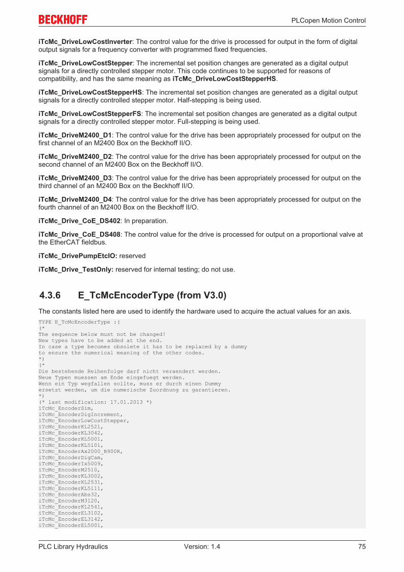
PLCopen Motion Control
PLC Library Hydraulics 75Version: 1.4
iTcMc_DriveLowCostInverter: The control value for the drive is processed for output in the form of digitaloutput signals for a frequency converter with programmed fixed frequencies.
iTcMc_DriveLowCostStepper: The incremental set position changes are generated as a digital outputsignals for a directly controlled stepper motor. This code continues to be supported for reasons ofcompatibility, and has the same meaning as iTcMc_DriveLowCostStepperHS.
iTcMc_DriveLowCostStepperHS: The incremental set position changes are generated as a digital outputsignals for a directly controlled stepper motor. Half-stepping is being used.
iTcMc_DriveLowCostStepperFS: The incremental set position changes are generated as a digital outputsignals for a directly controlled stepper motor. Full-stepping is being used.
iTcMc_DriveM2400_D1: The control value for the drive has been appropriately processed for output on thefirst channel of an M2400 Box on the Beckhoff II/O.
iTcMc_DriveM2400_D2: The control value for the drive has been appropriately processed for output on thesecond channel of an M2400 Box on the Beckhoff II/O.
iTcMc_DriveM2400_D3: The control value for the drive has been appropriately processed for output on thethird channel of an M2400 Box on the Beckhoff II/O.
iTcMc_DriveM2400_D4: The control value for the drive has been appropriately processed for output on thefourth channel of an M2400 Box on the Beckhoff II/O.
iTcMc_Drive_CoE_DS402: In preparation.
iTcMc_Drive_CoE_DS408: The control value for the drive is processed for output on a proportional valve atthe EtherCAT fieldbus.
iTcMc_DrivePumpEtcIO: reserved
iTcMc_Drive_TestOnly: reserved for internal testing; do not use.
4.3.6 E_TcMcEncoderType (from V3.0)The constants listed here are used to identify the hardware used to acquire the actual values for an axis.TYPE E_TcMcEncoderType :((*The sequence below must not be changed!New types have to be added at the end.In case a type becomes obsolete it has to be replaced by a dummyto ensure the numerical meaning of the other codes.*)(*Die bestehende Reihenfolge darf nicht veraendert werden.Neue Typen muessen am Ende eingefuegt werden.Wenn ein Typ wegfallen sollte, muss er durch einen Dummyersetzt werden, um die numerische Zuordnung zu garantieren.*)(* last modification: 17.01.2013 *)iTcMc_EncoderSim,iTcMc_EncoderDigIncrement,iTcMc_EncoderLowCostStepper,iTcMc_EncoderKL2521,iTcMc_EncoderKL3042,iTcMc_EncoderKL5001,iTcMc_EncoderKL5101,iTcMc_EncoderAx2000_B900R,iTcMc_EncoderDigCam,iTcMc_EncoderIx5009,iTcMc_EncoderM2510,iTcMc_EncoderKL3002,iTcMc_EncoderKL2531,iTcMc_EncoderKL5111,iTcMc_EncoderAbs32,iTcMc_EncoderM3120,iTcMc_EncoderKL2541,iTcMc_EncoderEL3102,iTcMc_EncoderEL3142,iTcMc_EncoderEL5001,
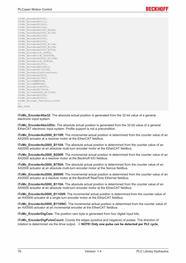
PLCopen Motion Control
PLC Library Hydraulics76 Version: 1.4
iTcMc_EncoderEL5101,iTcMc_EncoderEL5111,iTcMc_EncoderKL3062,iTcMc_EncoderKL3162,iTcMc_EncoderAx2000_B200R,iTcMc_EncoderAx2000_B110R,iTcMc_EncoderEL3162,iTcMc_EncoderKL2542,iTcMc_EncoderKL2545,iTcMc_EncoderAx2000_B110A,iTcMc_EncoderAx5000_B110A,iTcMc_EncoderAx2000_B750A,iTcMc_EncoderCoE_DS406,iTcMc_EncoderCoE_DS402SR,iTcMc_EncoderAx5000_B110SR,iTcMc_EncoderCoE_DS402A,iTcMc_EncoderEL2521,iTcMc_EncoderAbs32Etc,iTcMc_EncoderEL7201SR,iTcMc_EncoderDigPulseCount,iTcMc_EncoderEL3255,iTcMc_EncoderEL7047, iTcMc_DriveEM8908A, iTcMc_DriveEM8908C, iTcMc_EncoderCoE5001,iTcMc_EncoderEL7201A,iTcMc_DriveAx5000_B110INC,iTcMc_EncoderEL5032,iTcMc_EncoderEL5021,iTcMc_Encoder_TestOnly:=1000);END_TYPE
iTcMc_EncoderAbs32: The absolute actual position is generated from the 32-bit value of a generalelectronic input system.
iTcMc_EncoderAbs32Etc: The absolute actual position is generated from the 32-bit value of a generalEtherCAT electronic input system. Profile support is not a precondition.
iTcMc_EncoderAx2000_B110R: The incremental actual position is determined from the counter value of anAX2000 actuator at a resolver motor at the EtherCAT fieldbus.
iTcMc_EncoderAx2000_B110A: The absolute actual position is determined from the counter value of anAX2000 actuator at an absolute multi-turn encoder motor at the EtherCAT fieldbus.
iTcMc_EncoderAx2000_B200R: The incremental actual position is determined from the counter value of anAX2000 actuator at a resolver motor at the Beckhoff II/O fieldbus.
iTcMc_EncoderAx2000_B750A: The absolute actual position is determined from the counter value of anAX2000 actuator at an absolute multi-turn encoder motor at the Sercos fieldbus.
iTcMc_EncoderAx2000_B900R: The incremental actual position is determined from the counter value of anAX2000 actuator at a resolver motor at the Beckhoff RealTime Ethernet fieldbus.
iTcMc_EncoderAx5000_B110A: The absolute actual position is determined from the counter value of anAX5000 actuator at an absolute multi-turn encoder motor at the EtherCAT fieldbus.
iTcMc_EncoderAx5000_B110SR: The incremental actual position is determined from the counter value ofan AX5000 actuator at a single turn encoder motor at the EtherCAT fieldbus.
iTcMc_EncoderAx5000_B110INC: The incremental actual position is determined from the counter value ofan AX5000 actuator at an incremental encoder at the EtherCAT fieldbus.
iTcMc_EncoderDigCam: The position cam byte is generated from four digital input bits.
iTcMc_EncoderDigPulseCount: Counts the edges (positive and negative) of pulses. The direction ofrotation is determined via the drive output. NOTE! Only one pulse can be detected per PLC cycle.

PLCopen Motion Control
PLC Library Hydraulics 77Version: 1.4
iTcMc_EncoderDigIncrement: The incremental actual value of the axis is generated by evaluating twodigital input bits. These represent the A and B tracks of an incremental encoder, and are evaluated, inaccordance with the principle of a quadrature decoder, using quadruple evaluation. NOTE! Only one ofthe input bits may change its state in each PLC cycle. This means that the maximum velocity is oneincrement per TCycle.
iTcMc_EncoderEL2521: The incremental actual position is generated from the pulse counter of an EL2521Pulse Train terminal.
iTcMc_EncoderEL3102: The absolute actual position is generated from the ADW value of a ±10V EL3102analog input terminal.
iTcMc_EncoderEL3142: The absolute actual position is generated from the ADW value of a 0..20 mAEL3142 analog input terminal.
iTcMc_EncoderEL3162: The absolute actual position is generated from the ADW value of a 0..10V EL3162analog input terminal.
iTcMc_EncoderEL3255: In preparation.
iTcMc_EncoderEL5021: The absolute actual position is generated from the counter value of an EL5021 sin/cos input terminal.
iTcMc_EncoderEL5032: The absolute actual position is generated from the counter value of an EL5032EnDat-2.2 input terminal.
iTcMc_EncoderEL5001: The absolute actual position is generated from the counter value from an EL5001SSI input terminal.
iTcMc_EncoderEL5101: The incremental actual position is generated from the counter value from anEL5101 input terminal.
iTcMc_EncoderEL5111: The incremental actual position is generated from the counter value from anEL5111 input terminal.
iTcMc_EncoderEL7041: The incremental actual position is generated from the pulse counter (motor pulseor encoder) of an EL7041 stepper motor terminal.
iTcMc_EncoderEL7201SR: The incremental actual position is generated from the counter value from anEL7201 servo terminal.
iTcMc_EncoderCoE_DS402A: In preparation.
iTcMc_EncoderCoE_DS402SR: In preparation.
iTcMc_EncoderCoE_DS406: An encoder with CoE_406 support at the EtherCAT fieldbus.
iTcMc_EncoderIx5009: The absolute actual position is generated from the counter value of an SSI IP/IE5009 Fieldbus Box.
iTcMc_EncoderKL2521: The incremental actual position is generated from the pulse counter of a KL2521Pulse Train terminal.
iTcMc_EncoderKL2531: The incremental actual position is generated from the pulse counter of a KL2531stepper motor terminal.
iTcMc_EncoderKL2541: The incremental actual position is generated from the pulse counter (motor pulseor encoder) of a KL2541 stepper motor terminal.
iTcMc_EncoderKL2542: The incremental actual position is generated from the counter value from aKL2542 input terminal.
iTcMc_EncoderKL2545: The incremental actual position is generated from the counter value from aKL2542 input terminal.
iTcMc_EncoderKL3002: The absolute actual position is generated from the ADW value of a ±10V KL3002analog input terminal.
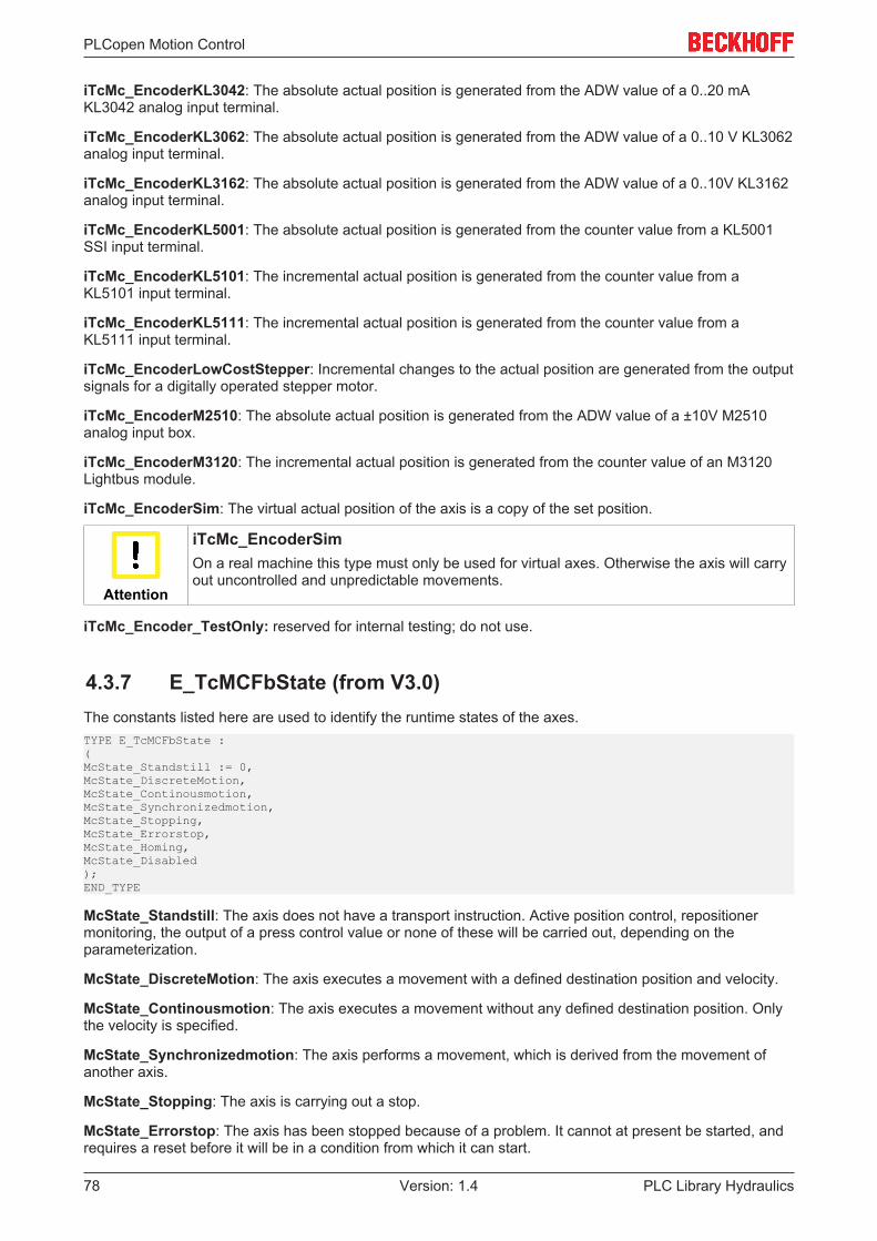
PLCopen Motion Control
PLC Library Hydraulics78 Version: 1.4
iTcMc_EncoderKL3042: The absolute actual position is generated from the ADW value of a 0..20 mAKL3042 analog input terminal.
iTcMc_EncoderKL3062: The absolute actual position is generated from the ADW value of a 0..10 V KL3062analog input terminal.
iTcMc_EncoderKL3162: The absolute actual position is generated from the ADW value of a 0..10V KL3162analog input terminal.
iTcMc_EncoderKL5001: The absolute actual position is generated from the counter value from a KL5001SSI input terminal.
iTcMc_EncoderKL5101: The incremental actual position is generated from the counter value from aKL5101 input terminal.
iTcMc_EncoderKL5111: The incremental actual position is generated from the counter value from aKL5111 input terminal.
iTcMc_EncoderLowCostStepper: Incremental changes to the actual position are generated from the outputsignals for a digitally operated stepper motor.
iTcMc_EncoderM2510: The absolute actual position is generated from the ADW value of a ±10V M2510analog input box.
iTcMc_EncoderM3120: The incremental actual position is generated from the counter value of an M3120Lightbus module.
iTcMc_EncoderSim: The virtual actual position of the axis is a copy of the set position.
Attention
iTcMc_EncoderSimOn a real machine this type must only be used for virtual axes. Otherwise the axis will carryout uncontrolled and unpredictable movements.
iTcMc_Encoder_TestOnly: reserved for internal testing; do not use.
4.3.7 E_TcMCFbState (from V3.0)The constants listed here are used to identify the runtime states of the axes.TYPE E_TcMCFbState :(McState_Standstill := 0,McState_DiscreteMotion,McState_Continousmotion,McState_Synchronizedmotion,McState_Stopping,McState_Errorstop,McState_Homing,McState_Disabled);END_TYPE
McState_Standstill: The axis does not have a transport instruction. Active position control, repositionermonitoring, the output of a press control value or none of these will be carried out, depending on theparameterization.
McState_DiscreteMotion: The axis executes a movement with a defined destination position and velocity.
McState_Continousmotion: The axis executes a movement without any defined destination position. Onlythe velocity is specified.
McState_Synchronizedmotion: The axis performs a movement, which is derived from the movement ofanother axis.
McState_Stopping: The axis is carrying out a stop.
McState_Errorstop: The axis has been stopped because of a problem. It cannot at present be started, andrequires a reset before it will be in a condition from which it can start.

PLCopen Motion Control
PLC Library Hydraulics 79Version: 1.4
McState_Homing: The axis is homing.
McState_Disabled: The controller enable of the axis is FALSE.
4.3.8 E_TcMcHomingType (from V3.0)The constants listed here are used to identify the referencing method of the axes.TYPE E_TcMcHomingType :(iTcMc_HomingOnBlock,iTcMc_HomingOnIndex,iTcMc_HomingOnSync,iTcMc_HomingOnMultiSync,iTcMc_HomingOnExec);END_TYPE
iTcMc_HomingOnBlock: The axis is moved in the direction specified byST_TcHydAxParam.bEnc_RefIndexPositive with ST_TcHydAxParam.fEnc_RefIndexVelo. If no movement isdetected over a period of 2 seconds, the fixed stop (block) is considered to have been reached. The actualvalue for the axis is set to the value of the reference position.
iTcMc_HomingOnIndex: The axis is moved in the direction specified byST_TcHydAxParam.bEnc_RefIndexPositive with ST_TcHydAxParam.fEnc_RefIndexVelo. The axis isstopped if the reference cam (bit 5, dwTcHydDcDwRefIndex) is detected inST_TcHydAxRtData.nDeCtrlDWord. It is then moved with ST_TcHydAxParam.fEnc_RefSyncVelo in thedirection specified by ST_TcHydAxParam.bEnc_RefSyncPositive until the reference cam has again beenleft. The actual value for the axis is set to the value of the reference position.
iTcMc_HomingOnSync: The axis is moved in the direction specified byST_TcHydAxParam.bEnc_RefIndexPositive with ST_TcHydAxParam.fEnc_RefIndexVelo. The axis isstopped if the reference cam (bit 5, dwTcHydDcDwRefIndex) is detected inST_TcHydAxRtData.nDeCtrlDWord. It is then moved with ST_TcHydAxParam.fEnc_RefSyncVelo in thedirection specified by ST_TcHydAxParam.bEnc_RefSyncPositive until the reference cam has again beenleft. The encoder's hardware latch is then activated, and the axis is moved on until the latch becomes valid.After the axis has stopped, the actual value for the axis is set to a value that is calculated from the referenceposition and from the distance covered since the encoder's sync pulse was detected.
iTcMc_HomingOnExec: The actual value of the axis is immediately set to the value of the referenceposition.
iTcMc_HomingOnMultiSync: The hardware latch of the encoder is activated. The axis is moved withST_TcHydAxParam.fEnc_RefSyncVelo in the direction specified byST_TcHydAxParam.bEnc_RefIndexPositive, until the latch has become valid twice. If the end of path isdetected before two sync pulses were detected, the process is repeated in the opposite direction. If this doesnot succeed either, the homing is aborted. Otherwise the current actual position is determined from thedistance of the sync pulses and the fEnc_BaseDistance.
4.3.9 E_TcMCParameter (from V3.0)The constants listed here are used for numbering parameters.TYPE E_TcMCParameter :((*===================================================================== A T T E N T I O N ======================================================================= These Codes are also used to identify parameters in files. == Any change of the meaning of any code here will make any file == incompatible without notice and may even cause a crash of == the control system! ======================================================================= CONSEQUENCE: Only adding new codes is allowed! ======================================================================= These codes are also used for ADS communication ======================================================================*)(*
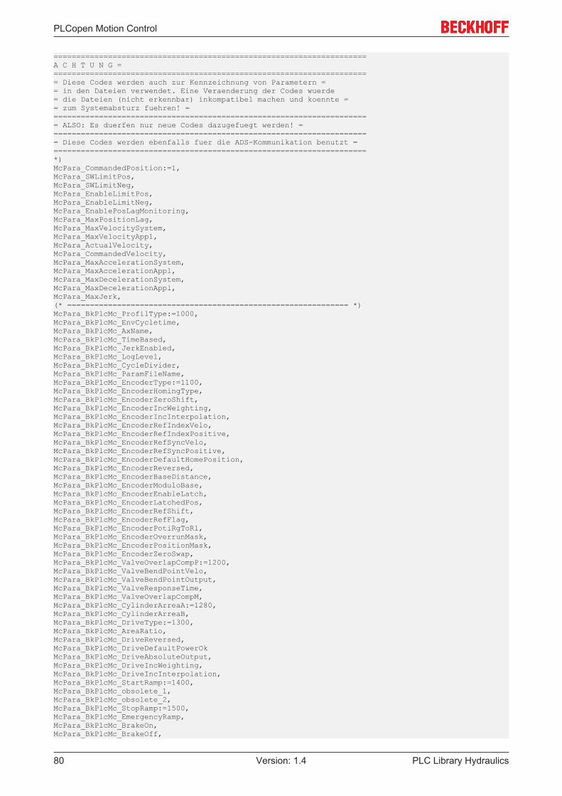
PLCopen Motion Control
PLC Library Hydraulics80 Version: 1.4
=====================================================================A C H T U N G ======================================================================= Diese Codes werden auch zur Kennzeichnung von Parametern == in den Dateien verwendet. Eine Veraenderung der Codes wuerde = die Dateien (nicht erkennbar) inkompatibel machen und koennte == zum Systemabsturz fuehren! ======================================================================= ALSO: Es duerfen nur neue Codes dazugefuegt werden! ======================================================================= Diese Codes werden ebenfalls fuer die ADS-Kommunikation benutzt ======================================================================*)McPara_CommandedPosition:=1,McPara_SWLimitPos,McPara_SWLimitNeg,McPara_EnableLimitPos,McPara_EnableLimitNeg,McPara_EnablePosLagMonitoring,McPara_MaxPositionLag,McPara_MaxVelocitySystem,McPara_MaxVelocityAppl,McPara_ActualVelocity,McPara_CommandedVelocity,McPara_MaxAccelerationSystem,McPara_MaxAccelerationAppl,McPara_MaxDecelerationSystem,McPara_MaxDecelerationAppl,McPara_MaxJerk,(* ============================================================== *)McPara_BkPlcMc_ProfilType:=1000,McPara_BkPlcMc_EnvCycletime,McPara_BkPlcMc_AxName,McPara_BkPlcMc_TimeBased,McPara_BkPlcMc_JerkEnabled,McPara_BkPlcMc_LogLevel,McPara_BkPlcMc_CycleDivider,McPara_BkPlcMc_ParamFileName,McPara_BkPlcMc_EncoderType:=1100,McPara_BkPlcMc_EncoderHomingType,McPara_BkPlcMc_EncoderZeroShift,McPara_BkPlcMc_EncoderIncWeighting,McPara_BkPlcMc_EncoderIncInterpolation,McPara_BkPlcMc_EncoderRefIndexVelo,McPara_BkPlcMc_EncoderRefIndexPositive,McPara_BkPlcMc_EncoderRefSyncVelo,McPara_BkPlcMc_EncoderRefSyncPositive,McPara_BkPlcMc_EncoderDefaultHomePosition,McPara_BkPlcMc_EncoderReversed,McPara_BkPlcMc_EncoderBaseDistance,McPara_BkPlcMc_EncoderModuloBase,McPara_BkPlcMc_EncoderEnableLatch,McPara_BkPlcMc_EncoderLatchedPos,McPara_BkPlcMc_EncoderRefShift,McPara_BkPlcMc_EncoderRefFlag,McPara_BkPlcMc_EncoderPotiRgToRl,McPara_BkPlcMc_EncoderOverrunMask,McPara_BkPlcMc_EncoderPositionMask,McPara_BkPlcMc_EncoderZeroSwap,McPara_BkPlcMc_ValveOverlapCompP:=1200,McPara_BkPlcMc_ValveBendPointVelo,McPara_BkPlcMc_ValveBendPointOutput,McPara_BkPlcMc_ValveResponseTime,McPara_BkPlcMc_ValveOverlapCompM,McPara_BkPlcMc_CylinderArreaA:=1280,McPara_BkPlcMc_CylinderArreaB,McPara_BkPlcMc_DriveType:=1300,McPara_BkPlcMc_AreaRatio,McPara_BkPlcMc_DriveReversed,McPara_BkPlcMc_DriveDefaultPowerOkMcPara_BkPlcMc_DriveAbsoluteOutput,McPara_BkPlcMc_DriveIncWeighting,McPara_BkPlcMc_DriveIncInterpolation,McPara_BkPlcMc_StartRamp:=1400,McPara_BkPlcMc_obsolete_1,McPara_BkPlcMc_obsolete_2,McPara_BkPlcMc_StopRamp:=1500,McPara_BkPlcMc_EmergencyRamp,McPara_BkPlcMc_BrakeOn,McPara_BkPlcMc_BrakeOff,
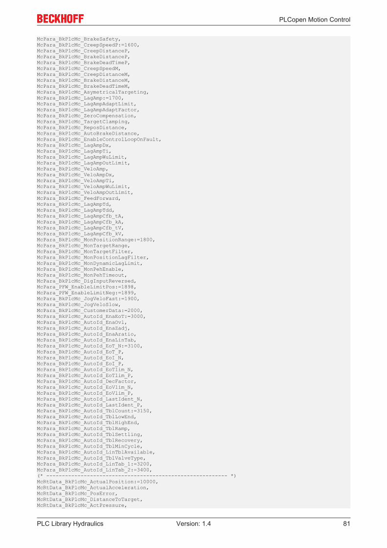
PLCopen Motion Control
PLC Library Hydraulics 81Version: 1.4
McPara_BkPlcMc_BrakeSafety,McPara_BkPlcMc_CreepSpeedP:=1600,McPara_BkPlcMc_CreepDistanceP,McPara_BkPlcMc_BrakeDistanceP,McPara_BkPlcMc_BrakeDeadTimeP,McPara_BkPlcMc_CreepSpeedM,McPara_BkPlcMc_CreepDistanceM,McPara_BkPlcMc_BrakeDistanceM,McPara_BkPlcMc_BrakeDeadTimeM,McPara_BkPlcMc_AsymetricalTargeting,McPara_BkPlcMc_LagAmp:=1700,McPara_BkPlcMc_LagAmpAdaptLimit,McPara_BkPlcMc_LagAmpAdaptFactor,McPara_BkPlcMc_ZeroCompensation,McPara_BkPlcMc_TargetClamping,McPara_BkPlcMc_ReposDistance,McPara_BkPlcMc_AutoBrakeDistance,McPara_BkPlcMc_EnableControlLoopOnFault,McPara_BkPlcMc_LagAmpDx,McPara_BkPlcMc_LagAmpTi,McPara_BkPlcMc_LagAmpWuLimit,McPara_BkPlcMc_LagAmpOutLimit,McPara_BkPlcMc_VeloAmp,McPara_BkPlcMc_VeloAmpDx,McPara_BkPlcMc_VeloAmpTi,McPara_BkPlcMc_VeloAmpWuLimit,McPara_BkPlcMc_VeloAmpOutLimit,McPara_BkPlcMc_FeedForward,McPara_BkPlcMc_LagAmpTd,McPara_BkPlcMc_LagAmpTdd,McPara_BkPlcMc_LagAmpCfb_tA,McPara_BkPlcMc_LagAmpCfb_kA,McPara_BkPlcMc_LagAmpCfb_tV,McPara_BkPlcMc_LagAmpCfb_kV,McPara_BkPlcMc_MonPositionRange:=1800,McPara_BkPlcMc_MonTargetRange,McPara_BkPlcMc_MonTargetFilter,McPara_BkPlcMc_MonPositionLagFilter,McPara_BkPlcMc_MonDynamicLagLimit,McPara_BkPlcMc_MonPehEnable,McPara_BkPlcMc_MonPehTimeout,McPara_BkPlcMc_DigInputReversed,McPara_PFW_EnableLimitPos:=1898, McPara_PFW_EnableLimitNeg:=1899, McPara_BkPlcMc_JogVeloFast:=1900,McPara_BkPlcMc_JogVeloSlow,McPara_BkPlcMc_CustomerData:=2000,McPara_BkPlcMc_AutoId_EnaEoT:=3000,McPara_BkPlcMc_AutoId_EnaOvl,McPara_BkPlcMc_AutoId_EnaZadj,McPara_BkPlcMc_AutoId_EnaAratio,McPara_BkPlcMc_AutoId_EnaLinTab,McPara_BkPlcMc_AutoId_EoT_N:=3100,McPara_BkPlcMc_AutoId_EoT_P,McPara_BkPlcMc_AutoId_EoI_N,McPara_BkPlcMc_AutoId_EoI_P,McPara_BkPlcMc_AutoId_EoTlim_N,McPara_BkPlcMc_AutoId_EoTlim_P,McPara_BkPlcMc_AutoId_DecFactor,McPara_BkPlcMc_AutoId_EoVlim_N, McPara_BkPlcMc_AutoId_EoVlim_P, McPara_BkPlcMc_AutoId_LastIdent_N, McPara_BkPlcMc_AutoId_LastIdent_P, McPara_BkPlcMc_AutoId_TblCount:=3150,McPara_BkPlcMc_AutoId_TblLowEnd,McPara_BkPlcMc_AutoId_TblHighEnd,McPara_BkPlcMc_AutoId_TblRamp,McPara_BkPlcMc_AutoId_TblSettling,McPara_BkPlcMc_AutoId_TblRecovery,McPara_BkPlcMc_AutoId_TblMinCycle,McPara_BkPlcMc_AutoId_LinTblAvailable,McPara_BkPlcMc_AutoId_TblValveType,McPara_BkPlcMc_AutoId_LinTab_1:=3200,McPara_BkPlcMc_AutoId_LinTab_2:=3400,(* ---------------------------------------------------------- *)McRtData_BkPlcMc_ActualPosition:=10000,McRtData_BkPlcMc_ActualAcceleration,McRtData_BkPlcMc_PosError,McRtData_BkPlcMc_DistanceToTarget,McRtData_BkPlcMc_ActPressure,

PLCopen Motion Control
PLC Library Hydraulics82 Version: 1.4
McRtData_BkPlcMc_ActPressureA,McRtData_BkPlcMc_ActPressureB,McRtData_BkPlcMc_ActForce,McRtData_BkPlcMc_ValvePressure,McRtData_BkPlcMc_SupplyPressure,McRtData_BkPlcMc_SetPosition,McRtData_BkPlcMc_SetVelocity,McRtData_BkPlcMc_SetAcceleration,McRtData_BkPlcMc_SetPressure,McRtData_BkPlcMc_SetOverride,McRtData_BkPlcMc_LatchPosition,McRtData_BkPlcMc_CtrlOutLag,McRtData_BkPlcMc_CtrlOutClamping,McRtData_BkPlcMc_CtrlOutOverlapComp,McRtData_BkPlcMc_TargetPosition,McRtData_BkPlcMc_NSDW:=11000,McRtData_BkPlcMc_DCDW,McRtData_BkPlcMc_ErrCode,McRtData_BkPlcMc_FbState,McRtData_BkPlcMc_CurStep,McRtData_BkPlcMc_ParamsUnsave,McRtData_BkPlcMc_RawPosition,McRtData_BkPlcMc_ActPosCams,McRtData_BkPlcMc_ReloadParams,McRtData_BkPlcMc_EncoderMinPos,McRtData_BkPlcMc_EncoderMaxPos,McRtData_BkPlcMc_BufferedEntries,(* ---------------------------------------------------------- *)(**)McPara_BkPlcMc_(**)McPara_BkPlcMc_FileMarkComplete:=32767 (* Ax.Params.bLinTabAvailable AutoIdent: .. / Au-toIdent: .. *));END_TYPE
McPara_ActualVelocity: The actual axis velocity.
McPara_BkPlcMc_AreaRatio: The direction-dependent velocity ratio.
McPara_BkPlcMc_AsymmetricalTargeting: Enable for the asymmetric target approach.
McPara_BkPlcMc_AutoID_EnaAratio: Automatic identification: Determining direction-related velocity ratio.
McPara_BkPlcMc_AutoID_DecFactor: Automatic identification: Factor for weighting the deceleration.
McPara_BkPlcMc_AutoID_EnaEoI_N: Automatic identification: Determined negative hard stop of thecylinder in increments.
McPara_BkPlcMc_AutoID_EnaEoI_P: Automatic identification: Determined positive hard stop of thecylinder in increments.
McPara_BkPlcMc_AutoID_EnaEoT: Automatic identification: Determining the hard stops of the cylinders.
McPara_BkPlcMc_AutoID_EnaLinTab: Automatic identification: Determining the characteristic curve.
McPara_BkPlcMc_AutoID_EnaOvl: Automatic identification: Determining the valve overlap.
McPara_BkPlcMc_AutoID_EnaZadj: Automatic identification: Determining the offsets.
McPara_BkPlcMc_AutoID_EoTlim_N: Automatic identification: Determined negative hard stop of thecylinder.
McPara_BkPlcMc_AutoID_EoTlim_P: Automatic identification: Determined positive hard stop of thecylinder.
McPara_BkPlcMc_AutoID_EoT_N: Automatic identification: Hard stop of the cylinder in negative direction.
McPara_BkPlcMc_AutoID_EoT_P: Automatic identification: Hard stop of the cylinder in positive direction.
McPara_BkPlcMc_AutoID_EoVlim_N: Automatic identification: Velocity limitation of the characteristiccurves determination in negative direction.
McPara_BkPlcMc_AutoID_EoVlim_P: Automatic identification: Velocity limitation of the characteristiccurves determination in positive direction.

PLCopen Motion Control
PLC Library Hydraulics 83Version: 1.4
McPara_BkPlcMc_AutoID_LastIdent_N: Automatic identification: The output value of the last successfulmeasurement in negative direction.
McPara_BkPlcMc_AutoID_LastIdent_P: Automatic identification: The output value of the last successfulmeasurement in positive direction.
McPara_BkPlcMc_AutoID_LinTab_1: Automatic identification: Points of the characteristic curve, relativevelocity.
McPara_BkPlcMc_AutoID_LinTab_2: Automatic identification: Points of the characteristic curve, relativeoutput.
McPara_BkPlcMc_AutoID_LinTblAvailable: This signal is set to TRUE at the end of a successfulcharacteristic curve measurement.
McPara_BkPlcMc_AutoID_MinCycle: Automatic identification: Minimum measuring distance.
McPara_BkPlcMc_AutoID_TblCount: Automatic identification: The number of required table points. Sincethe zero point is counted but is only present once, this parameter must always be an odd number. Valuesbetween 3 and 99 are accepted. A value of less than 11 is not recommended.
McPara_BkPlcMc_AutoID_TblHighEnd: Automatic identification: Upper end of the designated measuringsection.
McPara_BkPlcMc_AutoID_TblLowEnd: Automatic identification: Lower end of the designated measuringsection.
McPara_BkPlcMc_AutoID_TblRamp: Automatic identification: Ramp for establishing the measuring output.The specified time refers a change from zero to full scale. Smaller output changes are applied in a proportionof the time.
McPara_BkPlcMc_AutoID_TblRecovery: Automatic characteristic curve identification: Delay time in theevent of a change of direction.
McPara_BkPlcMc_AutoID_TblSettling: Automatic identification: Delay time between establishment of themeasuring output and the start of the measurement.
McPara_BkPlcMc_AutoID_TblValveType: Automatic identification: The expected characteristic curve type.
McPara_BkPlcMc_BrakeDeadTimeM: The brake dead time in negative direction.
McPara_BkPlcMc_BrakeDeadTimeP: The brake dead time in positive direction.
McPara_BkPlcMc_Auto_BrakeDistance: The enable for automatic calculation of the braking distance.
McPara_BkPlcMc_BrakeDistanceM: For asymmetric target approach: The braking distance time innegative direction.
McPara_BkPlcMc_BrakeDistanceP: The braking distance time in positive direction. For symmetric targetapproach: The braking distance time in negative direction.
McPara_BkPlcMc_BrakeOff: A delay between the active axis motion and the signal for activating a brake.
McPara_BkPlcMc_BrakeOn: A delay between the signal for releasing a brake and the active axis motion.
McPara_BkPlcMc_BrakeSafety: A delay between the active axis motion in one direction and active motionin the opposite direction.
McPara_BkPlcMc_CreepDistanceM: For asymmetric target approach: The creep distance in negativedirection.
McPara_BkPlcMc_CreepDistanceP: The creep distance in positive direction. For symmetric targetapproach: The creep distance in negative direction.
McPara_BkPlcMc_CreepSpeedM: For asymmetric target approach: The creep speed in negative direction.
McPara_BkPlcMc_CreepSpeedP: The creep speed in positive direction. For symmetric target approach:The creep speed in negative direction.

PLCopen Motion Control
PLC Library Hydraulics84 Version: 1.4
McPara_BkPlcMc_CustomerData: A field with parameters that can be used freely by an application. Theseparameter are stored and loaded with the axis parameters.
McPara_BkPlcMc_CycleDevider: reserved, not implemented.
McPara_BkPlcMc_CylinderArreaA: The cylinder area of the cylinder side pushing in positive direction.
McPara_BkPlcMc_CylinderArreaB: The cylinder area of the cylinder side pushing in negative direction.
McPara_BkPlcMc_DigInputsReversed: Enable for inversion of the input signals of an axis with digitalposition sensors.
McPara_BkPlcMc_DriveAbsoluteOutput: Enable for absolute value formation during output adjustment.
McPara_BkPlcMc_DriveDefaultPowerOk: Drive power is assumed to be available adopted; no hardwaresignal required.
McPara_BkPlcMc_DriveIncInterpolation: Interpolation of the output adjustment.
McPara_BkPlcMc_DriveIncWeighting: Weighting of the output adjustment.
McPara_BkPlcMc_DriveReversed: Enable for inverted output adjustment.
McPara_BkPlcMc_DriveType: Type of drive adjustment.
McPara_BkPlcMc_EmergencyRamp: In the event of an emergency stop: The time for braking frommaximum velocity to standstill.
McPara_BkPlcMc_EnableControlLoopOnFaults: Enable for position control in the event of axis errors.
McPara_BkPlcMc_EncoderBaseDistance: Reserved for distance-coded encoders.
McPara_BkPlcMc_EncoderDefaultHomePosition: Axes with incremental distance measuring system: Adefault value for homing.
McPara_BkPlcMc_EncoderEnableLatch: Enable for the latch function of an encoder hardware.
McPara_BkPlcMc_EncoderHomingType: Axes with incremental distance measuring system: The defaulthoming method.
McPara_BkPlcMc_EncoderIncInterpolation: The increment interpolation of the encoder evaluation.
McPara_BkPlcMc_EncoderIncWeighting: The increment weighting of the encoder evaluation.
McPara_BkPlcMc_EncoderModuloBase: reserved, not implemented.
McPara_BkPlcMc_EncoderLatchedPosition: The latched position during homing.
McPara_BkPlcMc_EncoderOverrunMask: A mask for detecting an encoder overflow.
McPara_BkPlcMc_EncoderPositionMask: A mask for isolating the valid bits within the mapped variables.
McPara_BkPlcMc_EncoderPotiRgToRl: For potentiometer encoders: The ratio of total potentiometerresistance to load resistance (input resistance of the terminal).
McPara_BkPlcMc_EncoderRefFlag: The homing status of the axis.
McPara_BkPlcMc_EncoderRefIndexPositive: Axes with incremental distance measuring system: Duringhoming the system looks for the index (cam) in positive direction.
McPara_BkPlcMc_EncoderRefIndexVelo: Axes with incremental distance measuring system: Duringhoming the system looks for the index (cam) with this velocity.
McPara_BkPlcMc_EncoderRefShift: Axes with incremental distance measuring system: Zero shift of theencoder evaluation.
McPara_BkPlcMc_EncoderRefSyncPositive: Axes with incremental distance measuring system: Duringhoming the system looks for the homing signal in positive direction.
PLCopen Motion Control
PLC Library Hydraulics 85Version: 1.4
McPara_BkPlcMc_EncoderRefSyncVelo: Axes with incremental distance measuring system: Duringhoming the system looks for the homing signal with this velocity.
McPara_BkPlcMc_EncoderReversed: Enable for inverted encoder evaluation.
McPara_BkPlcMc_EncoderType: Type of encoder evaluation.
McPara_BkPlcMc_EncoderZeroShift: Axes with absolute distance measuring system: Zero shift of theencoder evaluation.
McPara_BkPlcMc_EncoderZeroSwap: Block-by-block shifting of the counting range of the encoderevaluation.
McPara_BkPlcMc_EnvCycleTime: The cycle time of the task in which the core blocks (encoder, setpointgenerator, etc.) of the axis are called.
McPara_BkPlcMc_FeedForward: Pre-control weighting of the axis.
McPara_BkPlcMc_JerkEnabled: The control word for jerk limitation.
McPara_BkPlcMc_JogVeloFast: A default value for a fast jog velocity.
McPara_BkPlcMc_JogVeloSlow: A default value for a slow jog velocity.
McPara_BkPlcMc_LagAmp: Gain factor for the proportional component in the position controller.
McPara_BkPlcMc_LagAmpAdaptFactor: Reserved.
McPara_BkPlcMc_LagAmpAdaptLimit: Reserved.
McPara_BkPlcMc_LagAmpCfb_tA: Reserved.
McPara_BkPlcMc_LagAmpCfb_kA: Reserved.
McPara_BkPlcMc_LagAmpCfb_tV: Reserved.
McPara_BkPlcMc_LagAmpCfb_kV: Reserved.
McPara_BkPlcMc_LagAmpDx: Threshold value for the integrating component of the position controller.
McPara_BkPlcMc_LagAmpTd: Reserved.
McPara_BkPlcMc_LagAmpTdd: Reserved.
McPara_BkPlcMc_LagAmpTi: Time constant for the integrating component of the position controller.
McPara_BkPlcMc_LagAmpOutLimit: Output limitation for the position controller.
McPara_BkPlcMc_LagAmpWuLimit: Limitation (wind-up limit) for the integrating component of the positioncontroller.
McPara_BkPlcMc_LogLevel: Threshold value for message logging.
McPara_BkPlcMc_MonDynamicLagLimit: Tolerance for dynamic position lag monitoring.
McPara_BkPlcMc_MonPehEnable: Enable for monitoring of the ready message at the target.
McPara_BkPlcMc_MonPehTimeout: Filter time for monitoring of the ready message at the target.
McPara_BkPlcMc_MonPositionLagFilter: Filter time for position lag monitoring.
McPara_BkPlcMc_MonPositionRange: Tolerance for the position window.
McPara_BkPlcMc_MonTargetFilter: Filter time for the target window.
McPara_BkPlcMc_MonTargetRange: Tolerance for the target window.
McPara_BkPlcMc_obsolete_XYZ: Placeholder for parameters that are no longer supported. Theseparameter codes must not be reused for new parameters. To ensure this, such numerical values areassigned names of this form.

PLCopen Motion Control
PLC Library Hydraulics86 Version: 1.4
McPara_BkPlcMc_ParamFileName: Name of the parameter file.
McPara_BkPlcMc_ProfilType: Type of set value generation.
McPara_BkPlcMc_ReposDistance: Threshold value for automatic repositioning.
McPara_BkPlcMc_StartRamp: Only for certain set value generators: Acceleration ramp.
McPara_BkPlcMc_StopRamp: Only for certain set value generators: Braking ramp.
McPara_BkPlcMc_TargetClamping: Default output value for the terminal function.
McPara_BkPlcMc_TimeBased: Switching of setpoint generator: Time-based or displacement-based.
McPara_BkPlcMc_ValveBendPointOutput: Valve output for compensation of the characteristic curvebend.
McPara_BkPlcMc_ValveBendPointVelo: Velocity for compensation of the characteristic curve bend.
McPara_BkPlcMc_ValveOverlapCompM: Compensation of the valve overlap for the negative direction.
McPara_BkPlcMc_ValveOverlapCompP: Compensation of the valve overlap for the positive direction.
McPara_BkPlcMc_ValveResponseTime: Compensation of the valve response time.
McPara_BkPlcMc_VeloAmp: Gain factor for the proportional component in the velocity controller.
McPara_BkPlcMc_VeloAmpDx: Threshold value for the integrating component of the velocity controller.
McPara_BkPlcMc_VeloAmpTi: Time constant for the integrating component of the velocity controller.
McPara_BkPlcMc_VeloAmpOutLimit: Output limitation for the velocity controller.
McPara_BkPlcMc_VelopWuLimit: Limitation (wind-up limit) for the integrating component of the velocitycontroller.
McPara_BkPlcMc_ZeroCompensation: Offset compensation of the output.
McPara_CommandedPosition: The last commanded target position of the axis.
McPara_CommandedVelocity: The last commanded velocity of the axis.
McPara_EnableLimitNeg: Enable for the software limit switch in negative direction.
McPara_EnableLimitPos: Enable for the software limit switch in positive direction.
McPara_MaxAccelerationAppl: The maximum acceleration that can be commanded by the application.
McPara_MaxAccelerationSystem: The upper limit set by the system for the maximum acceleration that canbe commanded by the application.
McPara_MaxDecelerationAppl: The maximum deceleration that can be commanded by the application.
McPara_MaxDecelerationSystem: The upper limit set by the system for the maximum deceleration that canbe commanded by the application.
McPara_MaxJerk: The upper limit set by the system for the maximum jerk that can be commanded by theapplication.
McPara_MaxPositionLag: Threshold value for position lag monitoring.
McPara_MaxVelocityAppl: The maximum velocity that can be commanded by the application.
McPara_MaxVelocitySystem: The upper limit set by the system for the maximum velocity that can becommanded by the application.
McPara_PFW_Xyz: These parameters are reserved for a sector-specific solution.
McPara_SWLimitNeg: Software limit switch in negative direction.
McPara_SWLimitPos: Software limit switch in positive direction.

PLCopen Motion Control
PLC Library Hydraulics 87Version: 1.4
McRtData_BkPlcMc_ActForce: The actual force.
McRtData_BkPlcMc_AxName: The text-based name of the axis.
McRtData_BkPlcMc_ActPosCams: For axes with digital position sensors: The sensor signals.
McRtData_BkPlcMc_ActPressure: The actual differential pressure at the valve.
McRtData_BkPlcMc_ActPressureA: The actual pressure in the A-chamber of the cylinder.
McRtData_BkPlcMc_ActPressureB: The actual pressure in the B-chamber of the cylinder.
McRtData_BkPlcMc_ActualAcceleration: The actual acceleration.
McRtData_BkPlcMc_ActualPosition: The actual position.
McRtData_BkPlcMc_BufferedEntries: For axes with a command buffer: The number of bufferedcommands.
McRtData_BkPlcMc_CtrlOutOverlapComp: The current output component of the overlap compensation.
McRtData_BkPlcMc_CtrlOutClamping: The current value of the terminal output.
McRtData_BkPlcMc_CtrlOutLag: The current output of the position controller.
McRtData_BkPlcMc_CurStep: The current (internal) axis step. See also E_TcMcCurrentStep.
McRtData_BkPlcMc_DCDW: The control word of the axis with the enables (and other parameters). NOTE! There is no relationship with the control word of an external device.
McRtData_BkPlcMc_DistanceToTarget: The remaining distance to the target.
McRtData_BkPlcMc_EncoderMaxPos: Reserved.
McRtData_BkPlcMc_EncoderMinPos: Reserved.
McRtData_BkPlcMc_ErrCode: The current error code of the axis.
McRtData_BkPlcMc_FbState: The current axis step (defined by PLCopen). See also E_TcMCFbState.
McRtData_BkPlcMc_FileMarkComplete: In a parameter file: The logical end identifier.
McRtData_BkPlcMc_LatchPosition: The (offset) reference position. This is the position at which the actualposition was finally set during homing.
McRtData_BkPlcMc_NSDW: The axis status word with the operating states. NOTE! There is norelationship with the status word of an external device.
McRtData_BkPlcMc_ParamsUnsave: A TRUE here indicates that a parameter was changed significantly,but the parameter file was not yet written again NOTE! . This signal cannot be issued by the library, ifthe parameter was changed directly (without the write function blocks).
McRtData_BkPlcMc_PosError: The lag error.
McRtData_BkPlcMc_SetAcceleration: The current acceleration set value.
McRtData_BkPlcMc_SetOverride: The current override value.
McRtData_BkPlcMc_SetPosition: The current position set value.
McRtData_BkPlcMc_SetPressure: The set value for pressure or force regulators.
McRtData_BkPlcMc_SetVelocity: The current velocity set value.
McRtData_BkPlcMc_SupplyPressure: The actual supply pressure value.
McRtData_BkPlcMc_RawPosition: The actual position, which was not manipulated through an zero shift.
McRtData_BkPlcMc_ReloadParams: For parameter changes through the runtime: A request to thePlcMcManager to re-read the parameters.
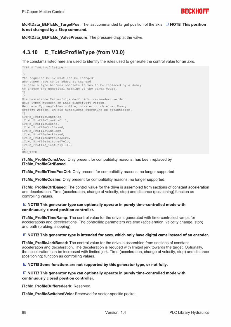
PLCopen Motion Control
PLC Library Hydraulics88 Version: 1.4
McRtData_BkPlcMc_TargetPos: The last commanded target position of the axis. NOTE! This positionis not changed by a Stop command.
McRtData_BkPlcMc_ValvePressure: The pressure drop at the valve.
4.3.10 E_TcMcProfileType (from V3.0)The constants listed here are used to identify the rules used to generate the control value for an axis.TYPE E_TcMcProfileType :((*The sequence below must not be changed!New types have to be added at the end.In case a type becomes obsolete it has to be replaced by a dummyto ensure the numerical meaning of the other codes.*)(*Die bestehende Reihenfolge darf nicht veraendert werden.Neue Typen muessen am Ende eingefuegt werden.Wenn ein Typ wegfallen sollte, muss er durch einen Dummyersetzt werden, um die numerische Zuordnung zu garantieren.*)iTcMc_ProfileConstAcc,iTcMc_ProfileTimePosCtrl,iTcMc_ProfileCosine,iTcMc_ProfileCtrlBased,iTcMc_ProfileTimeRamp,iTcMc_ProfileJerkBased,iTcMc_ProfileBufferedJerk,iTcMc_ProfileSwitchedVelo,iTcMc_Profile_TestOnly:=100);END_TYPE
iTcMc_ProfileConstAcc: Only present for compatibility reasons; has been replaced byiTcMc_ProfileCtrlBased.
iTcMc_ProfileTimePosCtrl: Only present for compatibility reasons; no longer supported.
iTcMc_ProfileCosine: Only present for compatibility reasons; no longer supported.
iTcMc_ProfileCtrlBased: The control value for the drive is assembled from sections of constant accelerationand deceleration. Time (acceleration, change of velocity, stop) and distance (positioning) function ascontrolling values.
NOTE! This generator type can optionally operate in purely time-controlled mode withcontinuously closed position controller.
iTcMc_ProfileTimeRamp: The control value for the drive is generated with time-controlled ramps foraccelerations and decelerations. The controlling parameters are time (acceleration, velocity change, stop)and path (braking, stopping).
NOTE! This generator type is intended for axes, which only have digital cams instead of an encoder.
iTcMc_ProfileJerkBased: The control value for the drive is assembled from sections of constantacceleration and deceleration. The deceleration is reduced with limited jerk towards the target. Optionally,the acceleration can be increased with limited jerk. Time (acceleration, change of velocity, stop) and distance(positioning) function as controlling values.
NOTE! Some functions are not supported by this generator type, or not fully.
NOTE! This generator type can optionally operate in purely time-controlled mode withcontinuously closed position controller.
iTcMc_ProfileBufferedJerk: Reserved.
iTcMc_ProfileSwitchedVelo: Reserved for sector-specific packet.

PLCopen Motion Control
PLC Library Hydraulics 89Version: 1.4
iTcMc_Profile_TestOnly: This type is only intended for internal testing of function block prototypes, whichhave not yet been released. It cannot be set via the PlcMcManager.
4.3.11 E_TcMcPressureReadingMode (from V3.0)The constants in this list are transferred to function blocks for logging actual force or pressure values [} 20].They determine which actual value should be updated in the ST_TcHydAxRtData [} 99] structure with theresult of the evaluation.TYPE E_TcMcPressureReadingMode :( iTcHydPressureReadingDefault, iTcHydPressureReadingActPressure, iTcHydPressureReadingActPressureA, iTcHydPressureReadingActPressureB, iTcHydPressureReadingActForce, iTcHydPressureReadingSupplyPressure, iTcHydPressureReadingValvePressure);END_TYPE
iTcHydPressureReadingDefault: The target variable depends on the function block being used.
iTcHydPressureReadingActPressure: The target variable is fActPressure. Some function blocksautomatically update fActPressureA and fActPressureB.
iTcHydPressureReadingActPressureA: The target variable is fActPressureA.
iTcHydPressureReadingActPressureB: The target variable is fActPressureA.
iTcHydPressureReadingActForce: The target variable is fActForce. Some function blocks automaticallyupdate fActPressure,fActPressureA and fActPressureB.
iTcHydPressureReadingSupplyPressure: The target variable is fSupplyPressure.
iTcHydPressureReadingValvePressure: The target variable is fValvePressure.
4.3.12 MC_BufferMode_BkPlcMc (from V3.0)The constants in this list are used for controlling blending according to PLC Open.TYPE MC_BufferMode_BkPlcMc :(Aborting_BkPlcMc := 0,Buffered_BkPlcMc,BlendingLow_BkPlcMc,BlendingPrevious_BkPlcMc,BlendingNext_BkPlcMc,BlendingHigh_BkPlcMc);END_TYPE
Aborting_BkPlcMc: The default case: The new command becomes active immediately and cancels anyother command that may already be active. The function block monitoring the aborted command will respondwith CommandAborted.
Buffered_BkPlcMc: For axes with command buffer: This command is started automatically once all previouscommands have been fully processed.
BlendingLow_BkPlcMc: For axes with command buffer: This command follows the previous commandwithout intermediate stop. If possible, the transition point is passed with the lower velocity of the commandsinvolved.
BlendingPrevious_BkPlcMc: For axes with command buffer: This command follows the previous commandwithout intermediate stop. If possible, the transition point is passed with the commanded velocity of theprevious command.
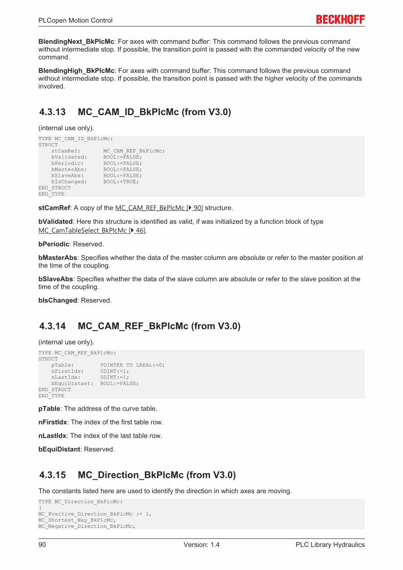
PLCopen Motion Control
PLC Library Hydraulics90 Version: 1.4
BlendingNext_BkPlcMc: For axes with command buffer: This command follows the previous commandwithout intermediate stop. If possible, the transition point is passed with the commanded velocity of the newcommand.
BlendingHigh_BkPlcMc: For axes with command buffer: This command follows the previous commandwithout intermediate stop. If possible, the transition point is passed with the higher velocity of the commandsinvolved.
4.3.13 MC_CAM_ID_BkPlcMc (from V3.0)(internal use only).TYPE MC_CAM_ID_BkPlcMc:STRUCT stCamRef: MC_CAM_REF_BkPlcMc; bValidated: BOOL:=FALSE; bPeriodic: BOOL:=FALSE; bMasterAbs: BOOL:=FALSE; bSlaveAbs: BOOL:=FALSE; bIsChanged: BOOL:=TRUE;END_STRUCTEND_TYPE
stCamRef: A copy of the MC_CAM_REF_BkPlcMc [} 90] structure.
bValidated: Here this structure is identified as valid, if was initialized by a function block of typeMC_CamTableSelect_BkPlcMc [} 46].
bPeriodic: Reserved.
bMasterAbs: Specifies whether the data of the master column are absolute or refer to the master position atthe time of the coupling.
bSlaveAbs: Specifies whether the data of the slave column are absolute or refer to the slave position at thetime of the coupling.
bIsChanged: Reserved.
4.3.14 MC_CAM_REF_BkPlcMc (from V3.0)(internal use only).TYPE MC_CAM_REF_BkPlcMc:STRUCT pTable: POINTER TO LREAL:=0; nFirstIdx: UDINT:=1; nLastIdx: UDINT:=1; bEquiDistant: BOOL:=FALSE;END_STRUCTEND_TYPE
pTable: The address of the curve table.
nFirstIdx: The index of the first table row.
nLastIdx: The index of the last table row.
bEquiDistant: Reserved.
4.3.15 MC_Direction_BkPlcMc (from V3.0)The constants listed here are used to identify the direction in which axes are moving.TYPE MC_Direction_BkPlcMc:(MC_Positive_Direction_BkPlcMc := 1,MC_Shortest_Way_BkPlcMc,MC_Negative_Direction_BkPlcMc,
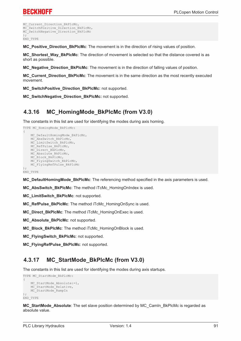
PLCopen Motion Control
PLC Library Hydraulics 91Version: 1.4
MC_Current_Direction_BkPlcMc,MC_SwitchPositive_Direction_BkPlcMc,MC_SwitchNegative_Direction_BkPlcMc);END_TYPE
MC_Positive_Direction_BkPlcMc: The movement is in the direction of rising values of position.
MC_Shortest_Way_BkPlcMc: The direction of movement is selected so that the distance covered is asshort as possible.
MC_Negative_Direction_BkPlcMc: The movement is in the direction of falling values of position.
MC_Current_Direction_BkPlcMc: The movement is in the same direction as the most recently executedmovement.
MC_SwitchPositive_Direction_BkPlcMc: not supported.
MC_SwitchNegative_Direction_BkPlcMc: not supported.
4.3.16 MC_HomingMode_BkPlcMc (from V3.0)The constants in this list are used for identifying the modes during axis homing.TYPE MC_HomingMode_BkPlcMc:( MC_DefaultHomingMode_BkPlcMc, MC_AbsSwitch_BkPlcMc, MC_LimitSwitch_BkPlcMc, MC_RefPulse_BkPlcMc, MC_Direct_BkPlcMc, MC_Absolute_BkPlcMc, MC_Block_BkPlcMc, MC_FlyingSwitch_BkPlcMc, MC_FlyingRefPulse_BkPlcMc);END_TYPE
MC_DefaultHomingMode_BkPlcMc: The referencing method specified in the axis parameters is used.
MC_AbsSwitch_BkPlcMc: The method iTcMc_HomingOnIndex is used.
MC_LimitSwitch_BkPlcMc: not supported.
MC_RefPulse_BkPlcMc: The method iTcMc_HomingOnSync is used.
MC_Direct_BkPlcMc: The method iTcMc_HomingOnExec is used.
MC_Absolute_BkPlcMc: not supported.
MC_Block_BkPlcMc: The method iTcMc_HomingOnBlock is used.
MC_FlyingSwitch_BkPlcMc: not supported.
MC_FlyingRefPulse_BkPlcMc: not supported.
4.3.17 MC_StartMode_BkPlcMc (from V3.0)The constants in this list are used for identifying the modes during axis startups.TYPE MC_StartMode_BkPlcMc:( MC_StartMode_Absolute:=1, MC_StartMode_Relative, MC_StartMode_RampIn);END_TYPE
MC_StartMode_Absolute: The set slave position determined by MC_CamIn_BkPlcMc is regarded asabsolute value.
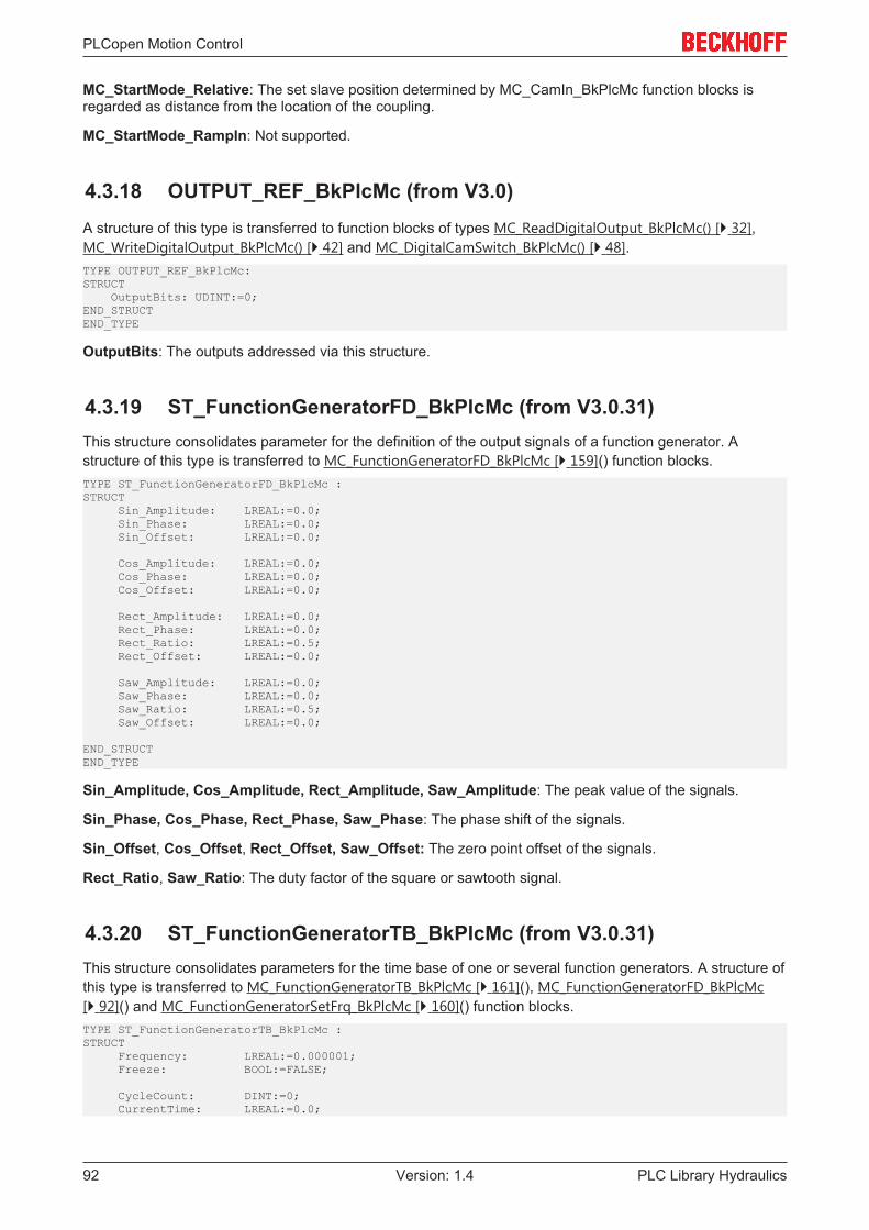
PLCopen Motion Control
PLC Library Hydraulics92 Version: 1.4
MC_StartMode_Relative: The set slave position determined by MC_CamIn_BkPlcMc function blocks isregarded as distance from the location of the coupling.
MC_StartMode_RampIn: Not supported.
4.3.18 OUTPUT_REF_BkPlcMc (from V3.0)A structure of this type is transferred to function blocks of types MC_ReadDigitalOutput_BkPlcMc() [} 32],MC_WriteDigitalOutput_BkPlcMc() [} 42] and MC_DigitalCamSwitch_BkPlcMc() [} 48].TYPE OUTPUT_REF_BkPlcMc:STRUCT OutputBits: UDINT:=0;END_STRUCTEND_TYPE
OutputBits: The outputs addressed via this structure.
4.3.19 ST_FunctionGeneratorFD_BkPlcMc (from V3.0.31)This structure consolidates parameter for the definition of the output signals of a function generator. Astructure of this type is transferred to MC_FunctionGeneratorFD_BkPlcMc [} 159]() function blocks.TYPE ST_FunctionGeneratorFD_BkPlcMc :STRUCT Sin_Amplitude: LREAL:=0.0; Sin_Phase: LREAL:=0.0; Sin_Offset: LREAL:=0.0;
Cos_Amplitude: LREAL:=0.0; Cos_Phase: LREAL:=0.0; Cos_Offset: LREAL:=0.0;
Rect_Amplitude: LREAL:=0.0; Rect_Phase: LREAL:=0.0; Rect_Ratio: LREAL:=0.5; Rect_Offset: LREAL:=0.0;
Saw_Amplitude: LREAL:=0.0; Saw_Phase: LREAL:=0.0; Saw_Ratio: LREAL:=0.5; Saw_Offset: LREAL:=0.0;
END_STRUCTEND_TYPE
Sin_Amplitude, Cos_Amplitude, Rect_Amplitude, Saw_Amplitude: The peak value of the signals.
Sin_Phase, Cos_Phase, Rect_Phase, Saw_Phase: The phase shift of the signals.
Sin_Offset, Cos_Offset, Rect_Offset, Saw_Offset: The zero point offset of the signals.
Rect_Ratio, Saw_Ratio: The duty factor of the square or sawtooth signal.
4.3.20 ST_FunctionGeneratorTB_BkPlcMc (from V3.0.31)This structure consolidates parameters for the time base of one or several function generators. A structure ofthis type is transferred to MC_FunctionGeneratorTB_BkPlcMc [} 161](), MC_FunctionGeneratorFD_BkPlcMc[} 92]() and MC_FunctionGeneratorSetFrq_BkPlcMc [} 160]() function blocks.TYPE ST_FunctionGeneratorTB_BkPlcMc :STRUCT Frequency: LREAL:=0.000001; Freeze: BOOL:=FALSE;
CycleCount: DINT:=0; CurrentTime: LREAL:=0.0;
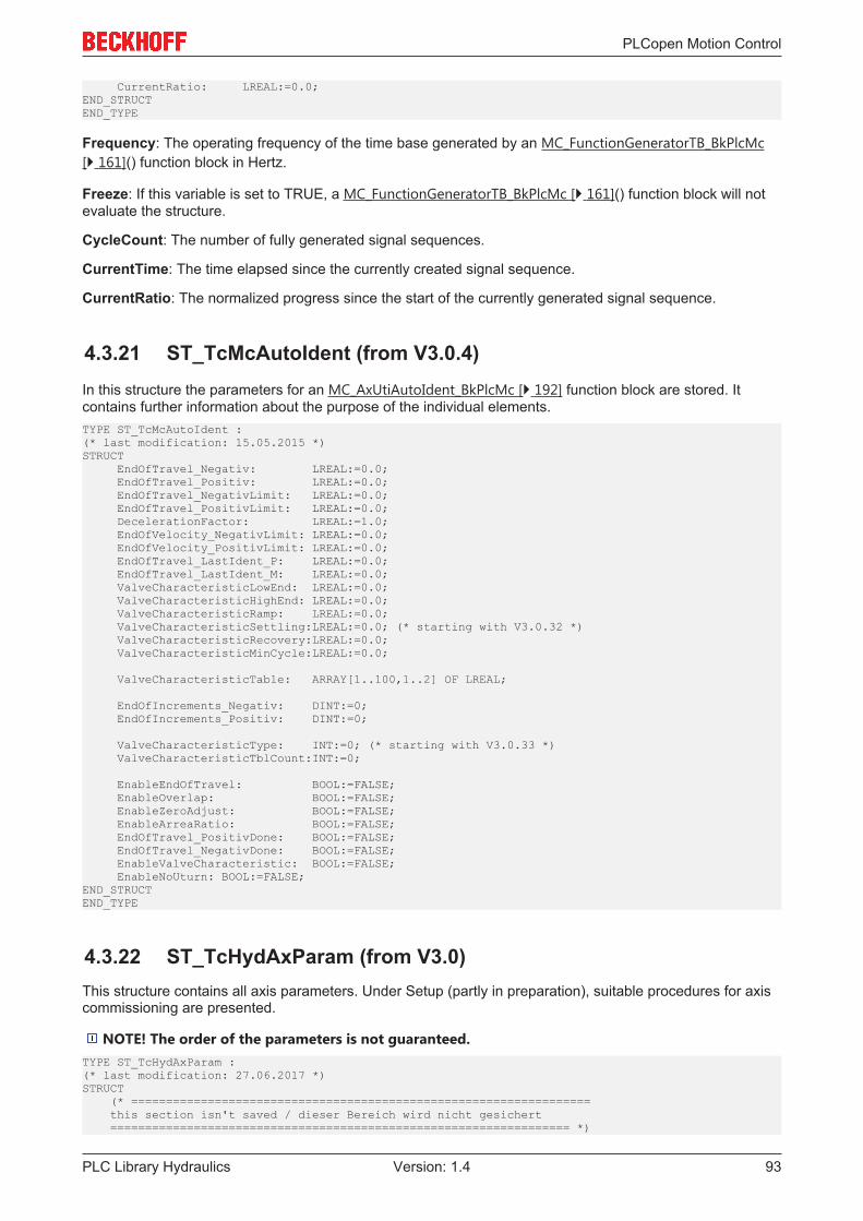
PLCopen Motion Control
PLC Library Hydraulics 93Version: 1.4
CurrentRatio: LREAL:=0.0;END_STRUCTEND_TYPE
Frequency: The operating frequency of the time base generated by an MC_FunctionGeneratorTB_BkPlcMc[} 161]() function block in Hertz.
Freeze: If this variable is set to TRUE, a MC_FunctionGeneratorTB_BkPlcMc [} 161]() function block will notevaluate the structure.
CycleCount: The number of fully generated signal sequences.
CurrentTime: The time elapsed since the currently created signal sequence.
CurrentRatio: The normalized progress since the start of the currently generated signal sequence.
4.3.21 ST_TcMcAutoIdent (from V3.0.4)In this structure the parameters for an MC_AxUtiAutoIdent_BkPlcMc [} 192] function block are stored. Itcontains further information about the purpose of the individual elements.TYPE ST_TcMcAutoIdent :(* last modification: 15.05.2015 *)STRUCT EndOfTravel_Negativ: LREAL:=0.0; EndOfTravel_Positiv: LREAL:=0.0; EndOfTravel_NegativLimit: LREAL:=0.0; EndOfTravel_PositivLimit: LREAL:=0.0; DecelerationFactor: LREAL:=1.0; EndOfVelocity_NegativLimit: LREAL:=0.0; EndOfVelocity_PositivLimit: LREAL:=0.0; EndOfTravel_LastIdent_P: LREAL:=0.0; EndOfTravel_LastIdent_M: LREAL:=0.0; ValveCharacteristicLowEnd: LREAL:=0.0; ValveCharacteristicHighEnd: LREAL:=0.0; ValveCharacteristicRamp: LREAL:=0.0; ValveCharacteristicSettling:LREAL:=0.0; (* starting with V3.0.32 *) ValveCharacteristicRecovery:LREAL:=0.0; ValveCharacteristicMinCycle:LREAL:=0.0;
ValveCharacteristicTable: ARRAY[1..100,1..2] OF LREAL;
EndOfIncrements_Negativ: DINT:=0; EndOfIncrements_Positiv: DINT:=0;
ValveCharacteristicType: INT:=0; (* starting with V3.0.33 *) ValveCharacteristicTblCount:INT:=0;
EnableEndOfTravel: BOOL:=FALSE; EnableOverlap: BOOL:=FALSE; EnableZeroAdjust: BOOL:=FALSE; EnableArreaRatio: BOOL:=FALSE; EndOfTravel_PositivDone: BOOL:=FALSE; EndOfTravel_NegativDone: BOOL:=FALSE; EnableValveCharacteristic: BOOL:=FALSE; EnableNoUturn: BOOL:=FALSE;END_STRUCTEND_TYPE
4.3.22 ST_TcHydAxParam (from V3.0)This structure contains all axis parameters. Under Setup (partly in preparation), suitable procedures for axiscommissioning are presented.
NOTE! The order of the parameters is not guaranteed.TYPE ST_TcHydAxParam :(* last modification: 27.06.2017 *)STRUCT (* ================================================================== this section isn't saved / dieser Bereich wird nicht gesichert ================================================================== *)
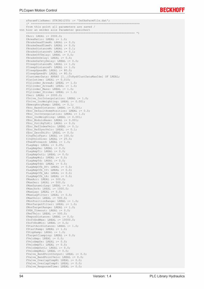
PLCopen Motion Control
PLC Library Hydraulics94 Version: 1.4
sParamFileName: STRING(255) := 'DefAxParmFile.dat'; (* ================================================================== from this point all parameters are saved /von hier an werden alle Parameter gesichert ================================================================== *) fAcc: LREAL := 2000.0; fAreaRatio: LREAL := 1.0; fBrakeDeadTimeM: LREAL := 0.0; fBrakeDeadTimeP: LREAL := 0.0; fBrakeDistanceM: LREAL := 0.1; fBrakeDistanceP: LREAL := 0.1; fBrakeOffDelay: LREAL := 0.0; fBrakeOnDelay: LREAL := 0.0; fBrakeSafetyDelay: LREAL := 0.0; fCreepDistanceM: LREAL := 1.0; fCreepDistanceP: LREAL := 1.0; fCreepSpeedM: LREAL := 80.0; fCreepSpeedP: LREAL := 80.0; fCustomerData: ARRAY [1..iTcHydfCustDataMaxIdx] OF LREAL; fCycletime: LREAL := 0.010; fCylinder_ArreaA: LREAL := 1.0; fCylinder_ArreaB: LREAL := 1.0; fCylinder_Mass: LREAL := 1.0; fCylinder_Stroke: LREAL := 1.0; fDec: LREAL := 2000.0; fDrive_IncInterpolation: LREAL := 1.0; fDrive_IncWeighting: LREAL := 0.001; fEmergencyRamp: LREAL := 0.1; fEnc_BaseDistance: LREAL := 0.001; fEnc_DefaultHomePosition: LREAL := 0.0; fEnc_IncInterpolation: LREAL := 1.0; fEnc_IncWeighting: LREAL := 0.001; fEnc_ModuloBase: LREAL := 0.001; fEnc_PotiRgToRl: LREAL := 0.0; fEnc_RefIndexVelo: LREAL := 0.1; fEnc_RefSyncVelo: LREAL := 0.1; fEnc_ZeroShift: LREAL := 0.0; fJogVeloFast: LREAL := 100.0; fJogVeloSlow: LREAL := 25.0; fFeedForward: LREAL := 1.0; fLagAmp: LREAL := 0.05; fLagAmpDx: LREAL := 0.0; fLagAmpTi: LREAL := 0.0; fLagAmpOutL: LREAL := 0.0; fLagAmpWuL: LREAL := 0.0; fLagAmpTd: LREAL := 0.0; fLagAmpTdd: LREAL := 0.0; fLagAmpCfb_kV: LREAL := 0.0; fLagAmpCfb_tV: LREAL := 0.0; fLagAmpCfb_kA: LREAL := 0.0; fLagAmpCfb_tA: LREAL := 0.0; fMaxAcc: LREAL := 500.0; fMaxDec: LREAL := 500.0; fMaxDynamicLag: LREAL := 0.0; fMaxJerk: LREAL := 1000.0; fMaxLag: LREAL := 0.0; fMaxLagFilter: LREAL := 0.0; fMaxVelo: LREAL := 500.0; fMonPositionRange: LREAL := 1.0; fMonTargetFilter: LREAL := 1.0; fMonTargetRange: LREAL := 1.0; fPEH_Timeout: LREAL := 0.0; fRefVelo: LREAL := 500.0; fReposDistance: LREAL := 0.0; fSoftEndMax: LREAL := 10000.0; fSoftEndMin: LREAL := 0.0; fStartAccDistance: LREAL := 1.0; fStartRamp: LREAL := 1.0; fStopRamp: LREAL := 1.0; fTargetClamping: LREAL := 0.0; fVeloAmp: LREAL := 0.0; fVeloAmpDx: LREAL := 0.0; fVeloAmpTi: LREAL := 0.0; fVeloAmpOutL: LREAL := 0.0; fVeloAmpWuL: LREAL := 0.0; fValve_BendPointOutput: LREAL := 0.0; fValve_BendPointVelo: LREAL := 0.0; fValve_OverlapCompM: LREAL := 0.0; fValve_OverlapCompP: LREAL := 0.0; fValve_ResponseTime: LREAL := 0.0;

PLCopen Motion Control
PLC Library Hydraulics 95Version: 1.4
fZeroCompensation: LREAL := 0.0;
nEnc_OverrunMask: DWORD := 0; nEnc_PositionMask: DWORD := 0; nEnc_ZeroSwap: DINT := 0; nDigInReversed: DINT := 0;
nCycleDivider: INT := 1; nDrive_Type: E_TcMcDriveType:=iTcMc_Drive_Customized; nEnc_HomingType: E_TcMcHomingType:=iTcMc_HomingOnBlock; nEnc_Type: E_TcMcEncoderType:=iTcMc_EncoderSim;
nJerkEnabled: WORD := 16#0101; nProfileType: E_TcMcProfileType:=iTcMc_ProfileCtrlBased;
bAsymetricalTargeting: BOOL := FALSE; bDrive_AbsoluteOutput: BOOL := FALSE; bDrive_DefaultPowerOk: BOOL := FALSE; bDrive_Reversed: BOOL := FALSE; bEnableAutoBrakeDistance: BOOL := FALSE; bEnableControlLoopOnFault: BOOL := FALSE; bEnc_RefIndexPositive: BOOL := FALSE; bEnc_RefSyncPositive: BOOL := FALSE; bEnc_Reversed: BOOL := FALSE; bMaxLagEna: BOOL := FALSE; bPEH_Enable: BOOL := FALSE; bPosCtrlAccEna: BOOL := FALSE; bSoftEndMaxEna: BOOL := FALSE; bSoftEndMinEna: BOOL := FALSE; bTimeBased: BOOL := FALSE; bLinTabAvailable: BOOL := FALSE; (*-----------------------------------------------------------------*)END_STRUCTEND_TYPE
bAsymetricalTargeting: From V3.0.8: If this parameter is TRUE, direction-dependent parameters takeeffect during target approach and overlap compensation.
bDrive_AbsoluteOutput: If this parameter is TRUE, control values outputs are always positive, irrespectiveof the direction.
bDrive_DefaultPowerOk: If this parameter is set, the PowerOk feedback in the ST_TcPlcDeviceInput [} 104]structure of the axis is ignored.
bDrive_Reversed: If this parameter is set, the control value output is negated.
bEnableAutoBrakeDistance: In preparation: If this parameter is TRUE, fCreepDistanceM andfCreepDistanceP are calculated automatically from fCreepSpeedM or fCreepSpeedP and fLagAmp.
bEnableControlLoopOnFault: In preparation: If this parameter is TRUE, the standstill position controller ofthe axis also becomes active in the event of an error. Requirement: Its parameter are suitable for this, andthe axis is in a suitable state.
bEnc_RefIndexPositive: If this parameter is set, while searching for the reference index (cam) duringhoming a positive control value is output, otherwise a negative value.
bEnc_RefSyncPositive: If this parameter is set, while searching for the reference pulse (sync pulse, zeropulse) during homing a positive control value is output, otherwise a negative value.
bEnc_Reversed: If this parameter is set, the actual position value is evaluated in negated form.
bLinTabAvailable: TRUE here means that each pointer was associated with a linearization table duringinitialization, which contains a successfully determined characteristic curve.
bMaxLagEna: This parameter activates lag monitoring.
bPEH_Enable: This parameter is used to active PEH monitoring.
bPosCtrlAccEna: obsolete, will be removed in the near future.
bSoftEndMaxEna: This parameter activates the upper software limit switch.
bSoftEndMinEna: This parameter activates the lower software limit switch.

PLCopen Motion Control
PLC Library Hydraulics96 Version: 1.4
bTimeBased: If this parameter is TRUE, the profile calculations are time-controlled. The position controller isalways active.
fAcc: [mm/s2] The absolute acceleration limitation of the axis.
fAreaRatio: [1] This parameter can be used to compensate the directionality of the velocity.
fBrakeDistance: [mm] Up to V3.0.7: At this not direction-dependent distance from the target, active profile-controlled control value generation ceases; optionally a standstill position controller or a different mechanismthat applies at target is activated.
fBrakeDistanceM: [mm] From V3.0.8: If bAsymetricalTargeting is TRUE, at this negative distance from thetarget active profile-controlled control value generation ceases; optionally a standstill position controller or adifferent mechanism that applies at target is activated.
fBrakeDistanceP: [mm] From V3.0.8: At this not direction-dependent or (if bAsymetricalTargeting isTRUE) positive distance from the target, active profile-controlled control value generation ceases; optionallya standstill position controller or a different mechanism that applies at target is activated.
fBrakeDeadTime: [s] Up to V3.0.7:
fBrakeDeadTimeM: [s] From V3.0.0.8:
fBrakeDeadTimeP: [s] From V3.0.0.8:
fBrakeOffDelay: [s] If this parameter is set to a value greater than 0, the control value generator observes adelay time between the positive edge at ST_TcPlcDeviceOutput [} 106].bBrakeOff and the start of theacceleration phase.
fBrakeOnDelay: [s] If this parameter is set to a value greater than 0, the control value generator observes adelay time between the end of the active profile generation and the negative edge at ST_TcPlcDeviceOutput[} 106].bBrakeOff.
fBrakeSafetyDelay: [s] If this parameter is set to a value greater than 0, the control value generator at thenegative edge at ST_TcPlcDeviceOutput [} 106].bBrakeOff observes a delay time between the end of anactive profile generation and the positive edge of the next travel command.
fCreepSpeed: [mm/s] Up to V3.0.7: This velocity is used, in non-direction-dependent mode, for the lastphase of the profile-controlled control value generation.
fCreepSpeedM: [mm/s] From V3.0.8: If bAsymetricalTargeting is TRUE and the direction of travel isnegative, this velocity is used for the last phase of the profile-controlled control value generation.
fCreepSpeedP: [mm/s] From V3.0.8: This velocity is used, in non-direction-dependent mode, or (ifbAsymetricalTargeting is TRUE) if the direction of travel is positive, for the last phase of the profile-controlled control value generation.
fCreepDistance: [mm] Up to V3.0.7: From this non-direction-dependent distance from the target,fCreepSpeed is used as control value for the last phase of the profile-controlled control value generation.
fCreepDistanceM: [mm] From V3.0.8: If bAsymetricalTargeting is TRUE, from this negative distance fromthe target from fCreepSpeedM is used as control value for the last phase of the profile-controlled controlvalue generation.
fCreepDistanceP: [mm] From V3.0.8: From this non-direction-dependent or (if bAsymetricalTargeting isTRUE) positive distance from the target, fCreepSpeedP is used as control value for the last phase of theprofile-controlled control value generation.
fCustomerData: 20 LREAL parameters are available for use by the application, as required. They areloaded and stored together with the other axis parameters. Library function blocks do not use theseparameters independently, by the application can instruct to use them based on the type of call.
fCycletime: [s] The cycle time of the PLC task, from which the library function blocks are called. This value isdetermined automatically by an MC_AxUtiStandardInit_BkPlcMc [} 182]() function block and may be used butnot be changed by the application.

PLCopen Motion Control
PLC Library Hydraulics 97Version: 1.4
fCylinder_ArreaA: [mm2] The active area of the cylinder, which is under pressure during a motion in positivedirection.
fCylinder_ArreaB: [mm2] The active area of the cylinder, which is under pressure during a motion innegative direction.
fCylinder_Mass: Reserved.
fCylinder_Stroke: Reserved.
fDec: [mm/s2] The absolute deceleration limitation of the axis.
fDrive_IncInterpolation: This parameter is used in some output devices for internal conversion of thevelocity control value.
fDrive_IncWeighting: This parameter is used in some output devices for internal conversion of the velocitycontrol value.
fEmergencyRamp: [s] This parameter specifies the time required for deceleration from fRefVelo tostandstill. It is used by different control value generators in response to unscheduled emergency stoprequests (lack of controller enable, fault condition, function block call).
fEnc_BaseDistance: [mm] This parameter is used for the evaluation of encoders with distance-coded zeromarks.
fEnc_DefaultHomePosition: [mm] This parameter can be used to store a position, which can be transferredas reference position to an MC_Home_BkPlcMc [} 57]() function block. If homing is triggered by thePlcMcManager, the value stored here is used in this way. If this is also intended to be the case if homing istriggered by the PLC application, this parameter should be transferred when the used function block iscalled.
fEnc_IncInterpolation: [mm/n] This parameter specifies the resolution with which the actual position of theaxis is determined.
fEnc_IncWeighting: [1] This parameter specifies the resolution with which the actual position of the axis isdetermined.
fEnc_PotiRgToRl: [1] It is used by some function blocks for linearization of simple potentiometerdisplacement transducer, which are subject to load from the input resistance of the interface electronics.
fEnc_RefIndexVelo: [1] This parameter specifies the control value as a proportion of fRefVelo, which isoutput during a search for the reference index (cam) during homing.
fEnc_RefSyncVelo: 81] This parameter specifies the control value as a proportion of fRefVelo, which isoutput during a search for the reference pulse (sync pulse, zero pulse) during homing.
fEnc_ZeroShift: [mm] This parameter shifts the zero point of the actual value determination of the axis.
fJogVeloFast: [mm/s] Set velocity for fast manual travel.
fJogVeloSlow: [mm/s] Set velocity for slow manual travel.
fLagAmp: [mm/s per mm → 1/s] The Kp amplification of the standstill position controller.
fLagAmpCfb_kA: [1] Optional: Weighting factor of the actual acceleration activation in the conditionfeedback of the position controller. Note: This parameter is only used byMC_AxRtPosPiControllerEx_BkPlcMc().
fLagAmpCfb_kV: : [1] Optional: Weighting factor of the actual velocity activation in the condition feedback ofthe position controller. Note: This parameter is only used by MC_AxRtPosPiControllerEx_BkPlcMc().
fLagAmpCfb_tA: [1] Optional: Filter time of the actual acceleration activation in the condition feedback ofthe position controller. Note: This parameter is only used by MC_AxRtPosPiControllerEx_BkPlcMc().
fLagAmpCfb_tV: : [1] Optional: Filter time of the actual velocity activation in the condition feedback of theposition controller. Note: This parameter is only used by MC_AxRtPosPiControllerEx_BkPlcMc().
fLagAmpDx: [mm] In preparation: The response window of the standstill position controller.

PLCopen Motion Control
PLC Library Hydraulics98 Version: 1.4
fLagAmpTd: [1] Optional: Rate time of the differential component of the position controller. Note: Thisparameter is only used by MC_AxRtPosPiControllerEx_BkPlcMc().
fLagAmpTdd: [s] Optional: Damping time of the differential component of the position controller. Note: Thisparameter is only used by MC_AxRtPosPiControllerEx_BkPlcMc().
fLagAmpTi: In preparation: The integration time of the standstill position controller.
fLagAmpOutL: In preparation: The output limitation of the standstill position controller.
fLagAmpWuL: In preparation: The limitation of the I component of the standstill position controller.
fMaxAcc: [mm/s2] The axis acceleration limitation applicable to the function blocks. This value is limited tofAcc.
fMaxDec: [mm/s2] The axis deceleration limitation applicable to the function blocks. This value is limited tofDec.
fMaxDynamicLag: [s] This parameter specifies one of the limit values for the lag monitoring.
fMaxJerk: [mm/s3] The axis jerk limitation applicable to the function blocks. This value is used ifiTcMc_ProfileJerkBased is set as profile type.
fMaxLag: [mm] This parameter specifies one of the limit values for the lag monitoring.
fMaxLagFilter: [s] This parameter specifies one of the limit values for the lag monitoring.
fMaxVelo: [mm/s] The maximum velocity that can be used by function blocks. If a function block tries to usea higher value, the value is generally limited accordingly without an error message. NOTE! Thisparameter is limited to fRefVelo.
fMonPositionRange: [mm] This parameter is used for target window monitoring.
fMonTargetFilter: [s] This parameter is used for target window monitoring.
fMonTargetRange: [mm] This parameter is used for target window monitoring.
fPEH_Timeout: [s] This parameter specifies the limit value for PEH monitoring.
fRefVelo: [mm/s] This parameter specifies the maximum absolute axis velocity.
fReposDistance: [mm] If this parameter is greater than 0 and the axis has moved beyond the target by morethan this distance, target positioning is automatically applied again.
fSoftEndMax: [mm] The upper (positive) software limit switch.
fSoftEndMin: [mm] The lower (negative) software limit switch.
fStartAccDistance: obsolete, will be removed in the near future.
fStartRamp: [s] This parameter specifies the time required in profile type iTcMc_ProfileTimeRamp toaccelerate to fRefVelo.
fStopRamp: [s] This parameter specifies the time required for deceleration from fRefVelo to standstill. It isused in profile type iTcMc_ProfileTimeRamp for the target approach, and also by control value generatorsin response to unscheduled stop requests (lack of feed enable, fault condition, function block call).
fTargetClamping: [v] If this parameter is set to a value greater than zero, this control value is output with thecorrect sign when a target is reached. A position control is suppressed.
fValve_BendPointOutput: [1] In valves with a bend in the characteristic curve, this parameter can be usedfor simple linearization.
fValve_BendPointVelo: [1] In valves with a bend in the characteristic curve, this parameter can be used forsimple linearization.
fValve_OverlapComp: [1] Up to V3.0.7: Compensation of a non-direction-dependent valve overlap.
fValve_OverlapCompM: [1] From V3.0.0.8: Compensation (if bAsymetricalTargeting = TRUE) for of avalve overlap used for the negative direction.
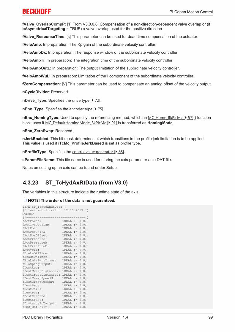
PLCopen Motion Control
PLC Library Hydraulics 99Version: 1.4
fValve_OverlapCompP: [1] From V3.0.0.8: Compensation of a non-direction-dependent valve overlap or (ifbAsymetricalTargeting = TRUE) a valve overlap used for the positive direction.
fValve_ResponseTime: [s] This parameter can be used for dead time compensation of the actuator.
fVeloAmp: In preparation: The Kp gain of the subordinate velocity controller.
fVeloAmpDx: In preparation: The response window of the subordinate velocity controller.
fVeloAmpTi: In preparation: The integration time of the subordinate velocity controller.
fVeloAmpOutL: In preparation: The output limitation of the subordinate velocity controller.
fVeloAmpWuL: In preparation: Limitation of the I component of the subordinate velocity controller.
fZeroCompensation: [V] This parameter can be used to compensate an analog offset of the velocity output.
nCycleDivider: Reserved.
nDrive_Type: Specifies the drive type [} 72].
nEnc_Type: Specifies the encoder type [} 75].
nEnc_HomingType: Used to specify the referencing method, which an MC_Home_BkPlcMc [} 57]() functionblock uses if MC_DefaultHomingMode_BkPlcMc [} 91] is transferred as HomingMode.
nEnc_ZeroSwap: Reserved.
nJerkEnabled: This bit mask determines at which transitions in the profile jerk limitation is to be applied.This value is used if iTcMc_ProfileJerkBased is set as profile type.
nProfileType: Specifies the control value generator [} 88].
sParamFileName: This file name is used for storing the axis parameter as a DAT file.
Notes on setting up an axis can be found under Setup.
4.3.23 ST_TcHydAxRtData (from V3.0)The variables in this structure indicate the runtime state of the axis.
NOTE! The order of the data is not guaranteed.TYPE ST_TcHydAxRtData :(* last modification: 12.10.2017 *)STRUCT(*-------------------------------*)fActForce: LREAL := 0.0;fActiveOverlap: LREAL := 0.0;fActPos: LREAL := 0.0;fActPosDelta: LREAL := 0.0;fActPosOffset: LREAL := 0.0;fActPressure: LREAL := 0.0;fActPressureA: LREAL := 0.0;fActPressureB: LREAL := 0.0;fActVelo: LREAL := 0.0;fBrakeOffTimer: LREAL := 0.0;fBrakeOnTimer: LREAL := 0.0;fBrakeSafetyTimer: LREAL := 0.0;fClampingOutput: LREAL := 0.0;fDestAcc: LREAL := 0.0;fDestCreepDistanceM: LREAL := 0.0;fDestCreepDistanceP: LREAL := 0.0;fDestCreepSpeedM: LREAL := 0.0;fDestCreepSpeedP: LREAL := 0.0;fDestDec: LREAL := 0.0;fDestJerk: LREAL := 0.0;fDestPos: LREAL := 0.0;fDestRampEnd: LREAL := 0.0;fDestSpeed: LREAL := 0.0;fDistanceToTarget: LREAL := 0.0;fEnc_RefShift: LREAL := 0.0;
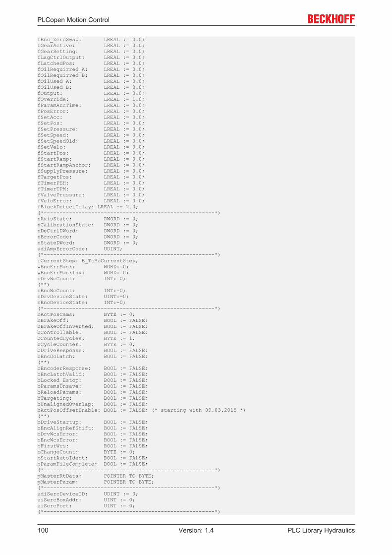
PLCopen Motion Control
PLC Library Hydraulics100 Version: 1.4
fEnc_ZeroSwap: LREAL := 0.0;fGearActive: LREAL := 0.0;fGearSetting: LREAL := 0.0;fLagCtrlOutput: LREAL := 0.0;fLatchedPos: LREAL := 0.0;fOilRequirred_A: LREAL := 0.0;fOilRequirred_B: LREAL := 0.0;fOilUsed_A: LREAL := 0.0;fOilUsed_B: LREAL := 0.0;fOutput: LREAL := 0.0;fOverride: LREAL := 1.0;fParamAccTime: LREAL := 0.0;fPosError: LREAL := 0.0;fSetAcc: LREAL := 0.0;fSetPos: LREAL := 0.0;fSetPressure: LREAL := 0.0;fSetSpeed: LREAL := 0.0;fSetSpeedOld: LREAL := 0.0;fSetVelo: LREAL := 0.0;fStartPos: LREAL := 0.0;fStartRamp: LREAL := 0.0;fStartRampAnchor: LREAL := 0.0;fSupplyPressure: LREAL := 0.0;fTargetPos: LREAL := 0.0;fTimerPEH: LREAL := 0.0;fTimerTPM: LREAL := 0.0;fValvePressure: LREAL := 0.0;fVeloError: LREAL := 0.0; fBlockDetectDelay: LREAL := 2.0;(*------------------------------------------------------*)nAxisState: DWORD := 0;nCalibrationState: DWORD := 0;nDeCtrlDWord: DWORD := 0;nErrorCode: DWORD := 0;nStateDWord: DWORD := 0;udiAmpErrorCode: UDINT;(*------------------------------------------------------*)iCurrentStep: E_TcMcCurrentStep;wEncErrMask: WORD:=0;wEncErrMaskInv: WORD:=0;nDrvWcCount: INT:=0;(**)nEncWcCount: INT:=0;nDrvDeviceState: UINT:=0;nEncDeviceState: INT:=0;(*------------------------------------------------------*)bActPosCams: BYTE := 0;bBrakeOff: BOOL := FALSE;bBrakeOffInverted: BOOL := FALSE;bControllable: BOOL := FALSE;bCountedCycles: BYTE := 1;bCycleCounter: BYTE := 0;bDriveResponse: BOOL := FALSE;bEncDoLatch: BOOL := FALSE;(**)bEncoderResponse: BOOL := FALSE;bEncLatchValid: BOOL := FALSE;bLocked_Estop: BOOL := FALSE;bParamsUnsave: BOOL := FALSE;bReloadParams: BOOL := FALSE;bTargeting: BOOL := FALSE;bUnalignedOverlap: BOOL := FALSE;bActPosOffsetEnable: BOOL := FALSE; (* starting with 09.03.2015 *)(**)bDriveStartup: BOOL := FALSE;bEncAlignRefShift: BOOL := FALSE;bDrvWcsError: BOOL := FALSE;bEncWcsError: BOOL := FALSE;bFirstWcs: BOOL := FALSE;bChangeCount: BYTE := 0;bStartAutoIdent: BOOL := FALSE;bParamFileComplete: BOOL := FALSE; (*------------------------------------------------------*)pMasterRtData: POINTER TO BYTE;pMasterParam: POINTER TO BYTE;(*------------------------------------------------------*)udiSercDeviceID: UDINT := 0;uiSercBoxAddr: UINT := 0;uiSercPort: UINT := 0;(*------------------------------------------------------*)

PLCopen Motion Control
PLC Library Hydraulics 101Version: 1.4
stPosCtrlr: stbkplcinternal_cplxctrl;stVeloCtrlr: stbkplcinternal_cplxctrl;(*------------------------------------------------------*)sTopBlockName: STRING(83) := '';(*------------------------------------------------------*)END_STRUCTEND_TYPE
bActPosCams: The current position cam of the axis. This value is only used, if iTcMc_EncoderDigCam isset as encoder type.
bActPosOffsetEnable: A TRUE in this variable activates actual value influencing. See also underfActPosOffset.
bBrakeOff: The control signal for an external brake. An output variable of the profile generators.
bBrakeOffInverted: The inverted bBrakeOff signal.
bChangeCount: This value is incremented with each parameter change.
bEncAlignRefShift: Reserved.
bEncDoLatch: This signal is used for communication by the MC_Home_BkPlcMc [} 57] andMC_AxRtEncoder_BkPlcMc [} 135] function blocks of the axis during homing.
bEncLatchValid: This signal is used for communication by the MC_Home_BkPlcMc [} 57] andMC_AxRtEncoder_BkPlcMc [} 135] function blocks of the axis during homing.
bLocked_Estop: A TRUE in this variable prevents the control value generators from exiting the stateiTcHydStateEmergencyBreak / McState_Errorstop, despite the fact that the drive outputs are reduced to 0.Used by MC_EmergencyStop_BkPlcMc [} 50] and MC_ImediateStop_BkPlcMc [} 59].
bParamFileComplete: This flag is set if a corresponding identifier was found at the end of the file when theparameters were loaded and the CRC check was successful.
bParamsUnsave: The function blocks MC_WriteParameter_BkPlcMc [} 43] andMC_WriteBoolParameter_BkPlcMc [} 41] set this flag if they change a parameter value. AnMC_AxParamSave_BkPlcMc [} 204] function block clears the flag when the parameters are successfullysaved. In online mode of the PlcMcManager [} 252], this flag is used for the status display.
bStartAutoIdent:
bUnalignedOverlap: The characteristic of the overlap compensation is defined here.
fActForce: [N, kN] Actual force of the cylinder. This value is usually determined by an acquisition functionblock for acquisition of actual force or pressure values [} 20].
fActiveOverlap: [1] The current output of the overlap compensation. An output variable of the profilegenerators.
fActPos: [mm] The current actual position of the axis. This value is usually determined by an encoderfunction block.
fActPosOffset: [mm] The offset used to influence the actual value. If bActPosOffsetEnable is TRUE, thisoffset is added to fActPos. If fActPosOffset changes, fActVelo is unaffected.
If bActPosOffsetEnable is TRUE, fActPosOffset takes effect immediately and without ramp.
NOTE! If actual value influencing is active during homing, bActPosOffset is taken into accountwhen the actual position is set.
Example: If the reference position is 100.0 mm and the offset is 1.0 mm, the actual position at the point ofthe zero pulse is set to 101.0 mm. If influencing is subsequently deactivated or set to 0.0, the actual positionat the point of the zero pulse shows the value 100.0, just like it would have done during homing withoutinfluencing.
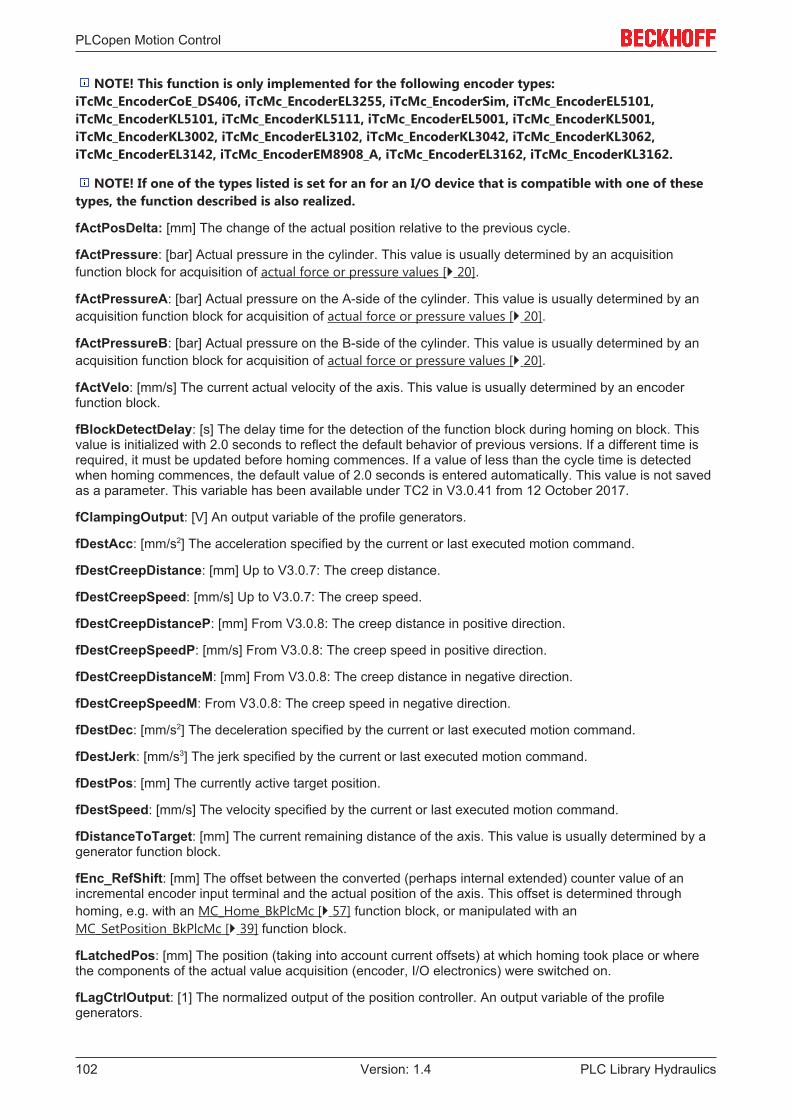
PLCopen Motion Control
PLC Library Hydraulics102 Version: 1.4
NOTE! This function is only implemented for the following encoder types:iTcMc_EncoderCoE_DS406, iTcMc_EncoderEL3255, iTcMc_EncoderSim, iTcMc_EncoderEL5101,iTcMc_EncoderKL5101, iTcMc_EncoderKL5111, iTcMc_EncoderEL5001, iTcMc_EncoderKL5001,iTcMc_EncoderKL3002, iTcMc_EncoderEL3102, iTcMc_EncoderKL3042, iTcMc_EncoderKL3062,iTcMc_EncoderEL3142, iTcMc_EncoderEM8908_A, iTcMc_EncoderEL3162, iTcMc_EncoderKL3162.
NOTE! If one of the types listed is set for an for an I/O device that is compatible with one of thesetypes, the function described is also realized.
fActPosDelta: [mm] The change of the actual position relative to the previous cycle.
fActPressure: [bar] Actual pressure in the cylinder. This value is usually determined by an acquisitionfunction block for acquisition of actual force or pressure values [} 20].
fActPressureA: [bar] Actual pressure on the A-side of the cylinder. This value is usually determined by anacquisition function block for acquisition of actual force or pressure values [} 20].
fActPressureB: [bar] Actual pressure on the B-side of the cylinder. This value is usually determined by anacquisition function block for acquisition of actual force or pressure values [} 20].
fActVelo: [mm/s] The current actual velocity of the axis. This value is usually determined by an encoderfunction block.
fBlockDetectDelay: [s] The delay time for the detection of the function block during homing on block. Thisvalue is initialized with 2.0 seconds to reflect the default behavior of previous versions. If a different time isrequired, it must be updated before homing commences. If a value of less than the cycle time is detectedwhen homing commences, the default value of 2.0 seconds is entered automatically. This value is not savedas a parameter. This variable has been available under TC2 in V3.0.41 from 12 October 2017.
fClampingOutput: [V] An output variable of the profile generators.
fDestAcc: [mm/s2] The acceleration specified by the current or last executed motion command.
fDestCreepDistance: [mm] Up to V3.0.7: The creep distance.
fDestCreepSpeed: [mm/s] Up to V3.0.7: The creep speed.
fDestCreepDistanceP: [mm] From V3.0.8: The creep distance in positive direction.
fDestCreepSpeedP: [mm/s] From V3.0.8: The creep speed in positive direction.
fDestCreepDistanceM: [mm] From V3.0.8: The creep distance in negative direction.
fDestCreepSpeedM: From V3.0.8: The creep speed in negative direction.
fDestDec: [mm/s2] The deceleration specified by the current or last executed motion command.
fDestJerk: [mm/s3] The jerk specified by the current or last executed motion command.
fDestPos: [mm] The currently active target position.
fDestSpeed: [mm/s] The velocity specified by the current or last executed motion command.
fDistanceToTarget: [mm] The current remaining distance of the axis. This value is usually determined by agenerator function block.
fEnc_RefShift: [mm] The offset between the converted (perhaps internal extended) counter value of anincremental encoder input terminal and the actual position of the axis. This offset is determined throughhoming, e.g. with an MC_Home_BkPlcMc [} 57] function block, or manipulated with anMC_SetPosition_BkPlcMc [} 39] function block.
fLatchedPos: [mm] The position (taking into account current offsets) at which homing took place or wherethe components of the actual value acquisition (encoder, I/O electronics) were switched on.
fLagCtrlOutput: [1] The normalized output of the position controller. An output variable of the profilegenerators.

PLCopen Motion Control
PLC Library Hydraulics 103Version: 1.4
fOilRequirred_A: [l/min] The oil consumption on the A-side, calculated taking into account the set velocity.
fOilRequirred_B: [l/min] The oil consumption on the B-side, calculated taking into account the set velocity.
fOilUsed_A: [l/min] The oil consumption on the A-side, calculated taking into account the actual velocity.
fOilUsed_B: [l/min] The oil consumption on the B-side, calculated taking into account the actual velocity.
fOutput: [1] The control value to be output. This variable is used for communication between theMC_AxRtFinish_BkPlcMc [} 175] and MC_AxRtDrive_BkPlcMc [} 125] function blocks.
fOverride: [1] The current axis velocity override.
fPosError: [mm] The current position error of the axis.
fSetPos: [mm] The current position command value of the axis.
fSetSpeed: [mm/s] The normalized set velocity of the axis. An output variable of the profile generators.
fSetAcc: [mm/s2] The current acceleration control value. An output variable of the profile generators.
fSetPressure: [bar] The set value for an optional pressure or force control must be stored here.
fStartPos: [mm] The start position of the current or last processed motion command.
fSupplyPressure: [bar] Supply pressure. This value is usually determined by an acquisition function blockfor acquisition of actual force or pressure values [} 20].
fTargetPos: [mm] The target position specified by the current or last processed motion command.
fValvePressure: [bar] Pressure drop at the valve. This value is usually determined by an acquisition functionblock for acquisition of actual force or pressure values [} 20].
iCurrentStep: The internal state of the control value generators. Values from E_TcMcCurrentStep [} 71].
nAxisState: The motion state of the axis.
nCalibrationState: The current homing state.
nDeCtrlDWord: The control signals [} 236] of the axis.
nErrorCode: The current error code [} 236] of the axis.
nStateDWord: The status signals [} 235] of the axis.
sTopBlockName: Most of the library function blocks called directly by application enter a debug ID here.
wEncErrMask:
wEncErrMaskInv:
All other elements of this structure are reserved for internal use. They are not guaranteed and must not beused or modified by the application.
4.3.24 ST_TcMcAuxDataLabels (from V3.0)This structure is used for storing the label texts for the customer-specific axis parameters. A structure of thistype can be linked with the axis through an MC_AxUtiStandardInit_BkPlcMc [} 182] via a pointer in theAxis_Ref_BkPlcMc [} 67] structure.TYPE ST_TcMcAuxDataLabels:STRUCT stLabel: ARRAY [1..20] OF STRING(20);END_STRUCTEND_TYPE
stLabel: The label texts.
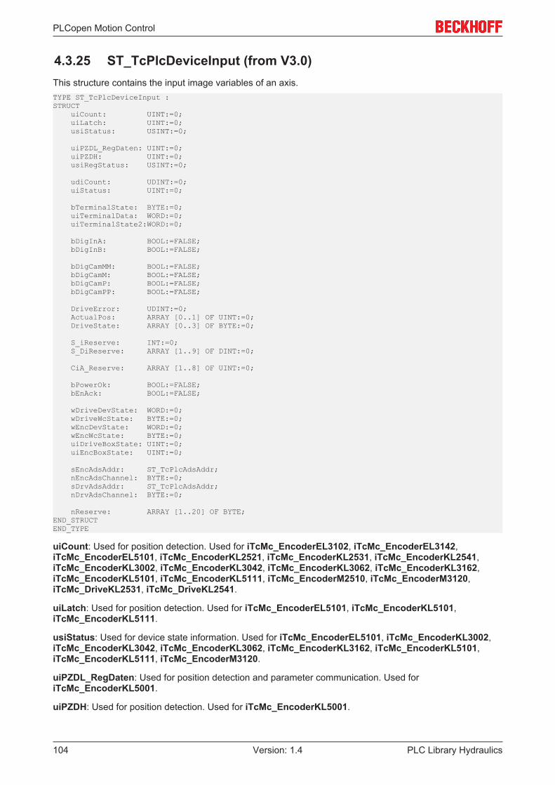
PLCopen Motion Control
PLC Library Hydraulics104 Version: 1.4
4.3.25 ST_TcPlcDeviceInput (from V3.0)This structure contains the input image variables of an axis.TYPE ST_TcPlcDeviceInput :STRUCT uiCount: UINT:=0; uiLatch: UINT:=0; usiStatus: USINT:=0;
uiPZDL_RegDaten: UINT:=0; uiPZDH: UINT:=0; usiRegStatus: USINT:=0;
udiCount: UDINT:=0; uiStatus: UINT:=0;
bTerminalState: BYTE:=0; uiTerminalData: WORD:=0; uiTerminalState2:WORD:=0;
bDigInA: BOOL:=FALSE; bDigInB: BOOL:=FALSE;
bDigCamMM: BOOL:=FALSE; bDigCamM: BOOL:=FALSE; bDigCamP: BOOL:=FALSE; bDigCamPP: BOOL:=FALSE;
DriveError: UDINT:=0; ActualPos: ARRAY [0..1] OF UINT:=0; DriveState: ARRAY [0..3] OF BYTE:=0;
S_iReserve: INT:=0; S_DiReserve: ARRAY [1..9] OF DINT:=0;
CiA_Reserve: ARRAY [1..8] OF UINT:=0;
bPowerOk: BOOL:=FALSE; bEnAck: BOOL:=FALSE;
wDriveDevState: WORD:=0; wDriveWcState: BYTE:=0; wEncDevState: WORD:=0; wEncWcState: BYTE:=0; uiDriveBoxState: UINT:=0; uiEncBoxState: UINT:=0;
sEncAdsAddr: ST_TcPlcAdsAddr; nEncAdsChannel: BYTE:=0; sDrvAdsAddr: ST_TcPlcAdsAddr; nDrvAdsChannel: BYTE:=0;
nReserve: ARRAY [1..20] OF BYTE;END_STRUCTEND_TYPE
uiCount: Used for position detection. Used for iTcMc_EncoderEL3102, iTcMc_EncoderEL3142,iTcMc_EncoderEL5101, iTcMc_EncoderKL2521, iTcMc_EncoderKL2531, iTcMc_EncoderKL2541,iTcMc_EncoderKL3002, iTcMc_EncoderKL3042, iTcMc_EncoderKL3062, iTcMc_EncoderKL3162,iTcMc_EncoderKL5101, iTcMc_EncoderKL5111, iTcMc_EncoderM2510, iTcMc_EncoderM3120,iTcMc_DriveKL2531, iTcMc_DriveKL2541.
uiLatch: Used for position detection. Used for iTcMc_EncoderEL5101, iTcMc_EncoderKL5101,iTcMc_EncoderKL5111.
usiStatus: Used for device state information. Used for iTcMc_EncoderEL5101, iTcMc_EncoderKL3002,iTcMc_EncoderKL3042, iTcMc_EncoderKL3062, iTcMc_EncoderKL3162, iTcMc_EncoderKL5101,iTcMc_EncoderKL5111, iTcMc_EncoderM3120.
uiPZDL_RegDaten: Used for position detection and parameter communication. Used foriTcMc_EncoderKL5001.
uiPZDH: Used for position detection. Used for iTcMc_EncoderKL5001.

PLCopen Motion Control
PLC Library Hydraulics 105Version: 1.4
usiRegStatus: Used for device state information. Used for iTcMc_EncoderEL5001,iTcMc_EncoderKL5001.
udiCount: Used for position detection. Used for iTcMc_EncoderEL5001.
uiStatus: Used for device state information. Used for iTcMc_EncoderAx2000_B110,iTcMc_DriveAx2000_B110.
bTerminalState: Used for parameter communication. Used for iTcMc_EncoderKL2521,iTcMc_EncoderKL2531, iTcMc_EncoderKL2541, iTcMc_DriveEL4132, iTcMc_DriveKL2521,iTcMc_DriveKL2531, iTcMc_DriveKL2541, iTcMc_DriveKL4032.
uiTerminalData: Reserved.
uiTerminalState2: Used for position detection. Used for iTcMc_EncoderKL2541.
bDigInA: Used for position detection. Used for iTcMc_EncoderDigIncrement.
bDigInB: Used for position detection. Used for iTcMc_EncoderDigIncrement.
bDigCamMM: Used for position detection. Used for iTcMc_EncoderDigCam.
bDigCamM: Used for position detection. Used for iTcMc_EncoderDigCam.
bDigCamP: Used for position detection. Used for iTcMc_EncoderDigCam.
bDigCamPP: Used for position detection. Used for iTcMc_EncoderDigCam.
DriveError: Used for device state information. Used for iTcMc_EncoderAx2000_B200,iTcMc_EncoderAx2000_B900.
ActualPos: Used for position detection. Used for iTcMc_EncoderAx2000_B110,iTcMc_EncoderAx2000_B200, iTcMc_EncoderAx2000_B900.
DriveState: Used for device state information. Used for iTcMc_EncoderAx2000_B200,iTcMc_EncoderAx2000_B900.
nReserve: Reserved.
S_iReserve: Reserved.
S_DiReserve: Reserved.
CiA_Reserve: Reserved.
bPowerOk: Optionally used for monitoring of a mains contactor. Used for iTcMc_DriveAx2000_B110,iTcMc_EncoderAx2000_B200, iTcMc_EncoderAx2000_B900.
bEnAck: Reserved.
wDriveDevState: Reserved.
wDriveWcState: Used for monitoring the connection to the actuator. Used foriTcMc_EncoderAx2000_B110, iTcMc_DriveAx2000_B110.
wEncDevState: Reserved.
wEncWcState: Used for monitoring the connection to the encoder. Used for iTcMc_EncoderAx2000_B110,iTcMc_DriveAx2000_B110, iTcMc_EncoderEL3102, iTcMc_EncoderEL3142, iTcMc_EncoderEL5001,iTcMc_EncoderEL5101.
uiDriveBoxState: Used for monitoring the connection to the actuator. Used for iTcMc_DriveAx2000_B200,iTcMc_DriveAx2000_B900.
uiEncBoxState: Used for monitoring the connection to the encoder. Used foriTcMc_EncoderAx2000_B200, iTcMc_EncoderAx2000_B900.
sEncAdsAddr: Used for parameter communication. Used for iTcMc_EncoderAx2000_B110,iTcMc_DriveAx2000_B110, iTcMc_EncoderEL3102, iTcMc_EncoderEL3142, iTcMc_EncoderEL5001,iTcMc_EncoderEL5101.
PLCopen Motion Control
PLC Library Hydraulics106 Version: 1.4
nEncAdsChannel: Used for parameter communication. Used for iTcMc_EncoderAx2000_B110,iTcMc_DriveAx2000_B110.
sDrvAdsAddr: Used for parameter communication. Used for iTcMc_EncoderAx2000_B110,iTcMc_DriveAx2000_B110.
nDrvAdsChannel: Used for parameter communication. Used for iTcMc_EncoderAx2000_B110,iTcMc_DriveAx2000_B110.
nReserve: Reserved.
4.3.26 ST_TcPlcDeviceOutput (from V3.0)This structure contains the output image variables of an axis.TYPE ST_TcPlcDeviceOutput :STRUCT nDacOut: INT:=0; bDigOutAp: BOOL:=FALSE; bDigOutAn: BOOL:=FALSE; bDigOutBp: BOOL:=FALSE; bDigOutBn: BOOL:=FALSE; uiCount: UINT:=0; uiDacOutA: UINT:=0; uiDacOutB: UINT:=0; bMovePos: BOOL:=FALSE; bMoveNeg: BOOL:=FALSE; bBrakeOff: BOOL:=FALSE; bBrakeOffInverted:BOOL:=FALSE; DriveCtrl: ARRAY [0..3] OF BYTE:=0; NominalVelo: DINT:=0; uiDriveCtrl: UINT:=0; S_iReserve: ARRAY [1..2] OF INT:=0; S_DiReserve: ARRAY [1..7] OF DINT:=0; CiA_Reserve: ARRAY [1..7] OF UINT:=0; bPowerOn: BOOL:=FALSE; bEnable: BOOL:=FALSE; bEnablePos: BOOL:=FALSE; bEnableNeg: BOOL:=FALSE; nResetState: BYTE:=0; usiCtrl: USINT:=0; uiTerminalData: WORD:=0; bTerminalCtrl: BYTE:=0; uiTerminalCtrl2: WORD:=0; nReserve: ARRAY [1..20] OF BYTE;END_STRUCTEND_TYPE
nDacOut: Used for control value outputs or parameter communication. Used for iTcMc_EncoderKL2531,iTcMc_EncoderKL2541, iTcMc_DriveEL4132, iTcMc_DriveKL2521, iTcMc_DriveKL2531,iTcMc_DriveKL2541, iTcMc_DriveKL4032, iTcMc_DriveM2400_Dn.
bDigOutAp: Used for control value output. Used for iTcMc_DriveLowCostStepper.
bDigOutAn: Used for control value output. Used for iTcMc_DriveLowCostStepper.
bDigOutBp: Used for control value output. Used for iTcMc_DriveLowCostStepper.
bDigOutBn: Used for control value output. Used for iTcMc_DriveLowCostStepper.
uiCount: Reserved.
uiDacOutA: Used for control value output. Used for iTcMc_EncoderIx2512_1Coil,iTcMc_EncoderIx2512_2Coil.
uiDacOutB: Used for control value output. Used for iTcMc_EncoderIx2512_2Coil.
bMovePos : Reserved.
bMoveNeg : Reserved.
bBrakeOff: Reserved.
PLCopen Motion Control
PLC Library Hydraulics 107Version: 1.4
bBrakeOffInverted: Reserved.
DriveCtrl: Used for device control signals. Used for iTcMc_EncoderAx2000_B200,iTcMc_DriveAx2000_B200, iTcMc_EncoderAx2000_B900, iTcMc_DriveAx2000_B900.
NominalVelo: Used for control value output. Used for iTcMc_DriveAx2000_B110,iTcMc_EncoderAx2000_B200, iTcMc_EncoderAx2000_B900.
uiDriveCtrl: Used for device control signals. Used for iTcMc_EncoderAx2000_B110,iTcMc_DriveAx2000_B110.
S_iReserve: Reserved.
S_DiReserve: Reserved.
CiA_Reserve: Reserved.
bPowerOn: Optionally used for controlling a mains contactor. Used for iTcMc_DriveAx2000_B110,iTcMc_EncoderAx2000_B200, iTcMc_EncoderAx2000_B900.
bEnable: Reserved.
bEnablePos: Reserved.
bEnableNeg: Reserved.
nResetState: Reserved.
usiCtrl: Used for device control signals or parameter communication. Used for iTcMc_EncoderEL5101,iTcMc_EncoderKL3002, iTcMc_EncoderKL3042, iTcMc_EncoderKL3062, iTcMc_EncoderKL3162,iTcMc_EncoderKL5101, iTcMc_EncoderKL5111, iTcMc_EncoderM3120.
uiTerminalData: Used for parameter communication. Used for iTcMc_EncoderKL2521,iTcMc_EncoderKL5001, iTcMc_EncoderKL5101, iTcMc_EncoderKL5111, iTcMc_DriveEL4132,iTcMc_DriveKL2521, iTcMc_DriveKL4032.
bTerminalCtrl: Used for parameter communication. Used for iTcMc_EncoderKL2521,iTcMc_EncoderKL2531, iTcMc_EncoderKL2541, iTcMc_DriveEL4132, iTcMc_DriveKL2521,iTcMc_DriveKL2531, iTcMc_DriveKL2541, iTcMc_DriveKL4032.
uiTerminalCtrl2: Used for device control signals. Used for iTcMc_EncoderKL2541, iTcMc_DriveKL2531,iTcMc_DriveKL2541.
nReserve: Reserved.
4.3.27 ST_TcPlcMcLogBuffer (from V3.0)A variable with this structure forms the LogBuffer of the library. Further information about creating a logbuffer can be found under FAQ #10 in the Knowledge Base [} 218].
Note
The data in this structure must not be modified by the application.
TYPE ST_TcMcLogBuffer:STRUCT ReadIdx: INT:=0; WriteIdx: INT:=0; MessageArr: ARRAY [0..19] OF ST_TcPlcMcLogEntry;END_STRUCTEND_TYPE
ST_TcPlcMcLogEntry [} 108]
ReadIdx: The read index of the buffer.
WriteIdx: The write index of the buffer.
PLCopen Motion Control
PLC Library Hydraulics108 Version: 1.4
MessageArr: The currently stored messages.
4.3.28 ST_TcPlcMcLogEntry (from V3.0)A variable with this structure contains a message of the LogBuffer of the library. Used as a component inST_TcPlcMcLogBuffer [} 107]. Further information about creating a log buffer can be found under FAQ #10 inthe Knowledge Base [} 218].
Note
The data in this structure must not be modified by the application.
TYPE ST_TcPlcMcLogEntry:STRUCT TimeLow: UDINT:=0; TimeHigh: UDINT:=0; LogLevel: DWORD:=0; Source: DWORD:=0; Msg: STRING(255); ArgType: INT:=0; diArg: DINT:=0; lrArg: LREAL:=0; sArg: STRING(255);END_STRUCTEND_TYPE
TimeLow, TimeHigh: The timestamp of the message. Records the time at which the message wasgenerated.
LogLevel: Indicates the urgency of the message. Only values from a specified pool of numbers [} 244]should appear here.
Source: Indicates the source of the message. Only values from a specified pool of numbers [} 244] shouldappear here.
Msg: The message text with an optional placeholder for a variable component.
ArgType: The type of the optional component.
diArg: If an optional component of type DINT is used, its value can be found here.
lrArg: If an optional component of type LREAL is used, its value can be found here.
sArg: If an optional component of type STRING is used, its value can be found here.
4.3.29 ST_TcPlcRegDataItem (from V3.0.7)This structure contains a parameter for a KL terminal. An ARRAY of elements of this type forms the typeST_TcPlcRegDataTable [} 109].TYPE ST_TcPlcRegDataItem :STRUCT Access: INT:=0; Select: INT:=-1; RegData: WORD:=0;END_STRUCTEND_TYPE
Access: The type of the operation to be executed is coded here. Details can be found underMC_AxUtiUpdateRegDriveTerm_BkPlcMc [} 209] or MC_AxUtiUpdateRegEncTerm_BkPlcMc [} 211].
Select: The address of the register in the terminal.
RegData: The parameters to be used for the operation to be executed.

PLCopen Motion Control
PLC Library Hydraulics 109Version: 1.4
4.3.30 ST_TcPlcRegDataTable (from V3.0.7)This structure contains a parameter set for a KL terminal. Such a table is processed by theMC_AxUtiUpdateRegDriveTerm_BkPlcMc [} 209] or MC_AxUtiUpdateRegEncTerm_BkPlcMc [} 211] functionblocks.TYPE ST_TcPlcRegDataTable :STRUCT RegDataItem: ARRAY [1..64] OF ST_TcPlcRegDataItem;END_STRUCTEND_TYPE
4.3.31 TRACK_REF_BkPlcMc (from V3.0)TYPE TRACK_REF_BkPlcMc:STRUCT Track: ARRAY [ciBkPlcMc_TrackRef_MinIdx..ciBkPlcMc_Track-Ref_MaxIdx] OF TRACK_REFTYPE_BkPlcMc;END_STRUCTEND_TYPE
TYPE TRACK_REFTYPE_BkPlcMc:STRUCT OnCompensation: LREAL; OffCompensation:LREAL; Hysteresis: LREAL;END_STRUCTEND_TYPE
OnCompensation: The switch-on dead time to be compensated in seconds.
OffCompensation: The switch-off dead time to be compensated in seconds.
Hysteresis: The axis must have moved away from the switching point by this distance before reaching of theswitching point is evaluated again.
If a positive value is specified as dead time compensation, signaling is delayed. A negative value leads toleading signalling.
NOTE! The time cannot be adhered to precisely, if the controlling parameter changes with afluctuating rate. If this controlling parameter is an actual axis position, the actual axis velocity mustbe constant.
4.4 System
4.4.1 Controller
4.4.1.1 MC_AxCtrlAutoZero_BkPlcMc (from V3.0)

PLCopen Motion Control
PLC Library Hydraulics110 Version: 1.4
The function block executes an automatic zero balance. This function block may only be used for zerooverlap valves.VAR_INPUT Enable: BOOL:=FALSE; EnableOnMoving: BOOL:=FALSE; OffsetLimit: LREAL:=0.0; Tn: LREAL:=0.0; Threshold: LREAL:=0.1; Filter: LREAL:=0.1;END_VARVAR_INOUT Axis: Axis_Ref_BkPlcMc;END_VARVAR_OUTPUT Error: BOOL; ErrorID: UDINT; Active: BOOL; Limiting: BOOL; Done: BOOL;END_VAR
Enable: This input controls the activity of the compensation.
EnableOnMoving: This input controls the activity of the compensation.
Tn: [s] The integral action time of the compensation. This is the time for a change by 10 V. Values greaterthan 100 s are recommended.
Threshold: [V] Parameter for the Done signal.
Filter: [s] Parameter for the Done signal.
OffsetLimit: [V] The value in fZeroCompensation is limited to this value.
Error: The occurrence of an error is indicated here.
ErrorID: An encoded indication of the cause of the error is provided here.
Active: Indicates that the function block actively adjusts the value of fZeroCompensation inST_TcHydAxParam [} 93].
Limiting: Indicates that the value of fZeroCompensation in ST_TcHydAxParam [} 93] has reached the limitspecified by OffsetLimit.
Done: Indicates leveling out of the offset compensation.
Axis: Here, the address of a variable of type Axis_Ref_BkPlcMc [} 67] should be transferred.
Purpose of the function block
If a hydraulic cylinder is drifting when the position controller is switched off (kP=0.0), or if there is apermanent lag error relative to the target when the position controller is active, this can be corrected by usinga zero overlap valve with offset compensation.
A hydraulic cylinder stops when it is in equilibrium of forces. In the simplest case (cylinder with identicalsurfaces, no external forces by gravity or a process) this equilibrium is fulfilled, if the same pressure acts onboth surfaces. For a differential cylinder, the pressures must be proportional to the inverse of the surfaces.Any external forces must be included. In order to achieve the required pressure conditions, a proportion ofthe system pressure is required as pressure difference. In the case of a zero overlap valve, this is defined bythe pressure gain characteristic.
Another possible reason for an offset is a difference between the hydraulic zero point of the valve and thelogical zero point of the output hardware. These are unavoidable manufacturing tolerances.
Therefore, a small valve excitation with up to ±0.5 V is required. Refer to the data sheets provided by thevalve and hardware manufacturers for further information.
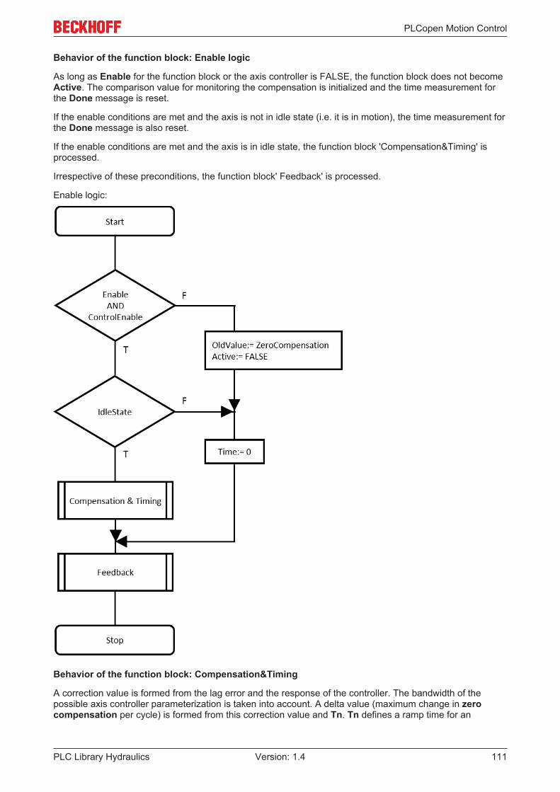
PLCopen Motion Control
PLC Library Hydraulics 111Version: 1.4
Behavior of the function block: Enable logic
As long as Enable for the function block or the axis controller is FALSE, the function block does not becomeActive. The comparison value for monitoring the compensation is initialized and the time measurement forthe Done message is reset.
If the enable conditions are met and the axis is not in idle state (i.e. it is in motion), the time measurement forthe Done message is also reset.
If the enable conditions are met and the axis is in idle state, the function block 'Compensation&Timing' isprocessed.
Irrespective of these preconditions, the function block' Feedback' is processed.
Enable logic:
Behavior of the function block: Compensation&Timing
A correction value is formed from the lag error and the response of the controller. The bandwidth of thepossible axis controller parameterization is taken into account. A delta value (maximum change in zerocompensation per cycle) is formed from this correction value and Tn. Tn defines a ramp time for an

PLCopen Motion Control
PLC Library Hydraulics112 Version: 1.4
increase by 10 V. The delta value is limited such that this ramp slope is not exceeded. In this way anexcessively fast change, during which the correction would become unstable, can be avoided. Valuesgreater than 100 seconds are recommended.
A tolerance threshold is used for compensation. In this case LagAmpDx (threshold value of the I componentin the position controller) is used.If the correction value is greater than or equal to the tolerance threshold and the actual velocity is greaterthan or equal to zero (i.e. the remaining correction value is not already reduced), the Active function block isused and the compensation is reduced in each cycle by the delta value described.If the correction value is less than or equal to the tolerance threshold and the actual velocity is less than orequal to zero (i.e. the remaining correction value is not already reduced), the Active function block is usedand the compensation is reduced in each cycle by the delta value described.If the magnitude of the correction value is smaller than the tolerance threshold, Active becomes FALSE.
If the compensation differs by more than the Threshold from the OldValue comparison value, the timemeasurement is reset and the current compensation is updated as a new comparison value. Otherwise, thetime measurement is increased with the cycle time. In this way, the time required to accumulate a change incompensation by at least the Threshold is logged.
Compensation&Timing:

PLCopen Motion Control
PLC Library Hydraulics 113Version: 1.4
Behavior of the function block: Feedback
The compensation is limited to ±OffsetLimit and signaled to Limiting.
Done is reported when the function block is active and the time measurement reaches the time set in Filter.Example: If Threshold is set to 0.05 and Filter to 2.0, Done is reported if the compensation has beenreadjusted by less than 0.05 V within the last 2 seconds.

PLCopen Motion Control
PLC Library Hydraulics114 Version: 1.4
Feedback
NOTE! The limitation to the range specified by OffsetLimit applies even if the function block is notactive. The Limiting output is updated.
The value OffsetLimit and ST_TcHydAxParam [} 93].fZeroCompensation are regarded as offset voltage.The value 10.0 therefore corresponds to full scale control. In general, a value between 0.1 and 1.0 makessense for OffsetLimit, depending on the application.
Integration of the function block in the application
In the call sequence for the function blocks of an axis, an MC_AxCtrlAutoZero_BkPlcMc function blockshould appear immediately before the MC_AxRtFinish_BkPlcMc [} 175]. If an MC_AxStandardBody_BkPlcMc[} 181] function block is called instead of the individual function blocks, MC_AxCtrlAutoZero_BkPlcMc shouldbe called before this function block.
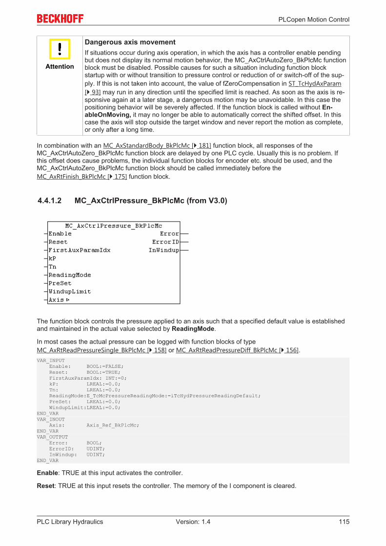
PLCopen Motion Control
PLC Library Hydraulics 115Version: 1.4
Attention
Dangerous axis movementIf situations occur during axis operation, in which the axis has a controller enable pendingbut does not display its normal motion behavior, the MC_AxCtrlAutoZero_BkPlcMc functionblock must be disabled. Possible causes for such a situation including function blockstartup with or without transition to pressure control or reduction of or switch-off of the sup-ply. If this is not taken into account, the value of fZeroCompensation in ST_TcHydAxParam[} 93] may run in any direction until the specified limit is reached. As soon as the axis is re-sponsive again at a later stage, a dangerous motion may be unavoidable. In this case thepositioning behavior will be severely affected. If the function block is called without En-ableOnMoving, it may no longer be able to automatically correct the shifted offset. In thiscase the axis will stop outside the target window and never report the motion as complete,or only after a long time.
In combination with an MC_AxStandardBody_BkPlcMc [} 181] function block, all responses of theMC_AxCtrlAutoZero_BkPlcMc function block are delayed by one PLC cycle. Usually this is no problem. Ifthis offset does cause problems, the individual function blocks for encoder etc. should be used, and theMC_AxCtrlAutoZero_BkPlcMc function block should be called immediately before theMC_AxRtFinish_BkPlcMc [} 175] function block.
4.4.1.2 MC_AxCtrlPressure_BkPlcMc (from V3.0)
The function block controls the pressure applied to an axis such that a specified default value is establishedand maintained in the actual value selected by ReadingMode.
In most cases the actual pressure can be logged with function blocks of typeMC_AxRtReadPressureSingle_BkPlcMc [} 158] or MC_AxRtReadPressureDiff_BkPlcMc [} 156].VAR_INPUT Enable: BOOL:=FALSE; Reset: BOOL:=TRUE; FirstAuxParamIdx: INT:=0; kP: LREAL:=0.0; Tn: LREAL:=0.0; ReadingMode:E_TcMcPressureReadingMode:=iTcHydPressureReadingDefault; PreSet: LREAL:=0.0; WindupLimit:LREAL:=0.0;END_VARVAR_INOUT Axis: Axis_Ref_BkPlcMc;END_VARVAR_OUTPUT Error: BOOL; ErrorID: UDINT; InWindup: UDINT;END_VAR
Enable: TRUE at this input activates the controller.
Reset: TRUE at this input resets the controller. The memory of the I component is cleared.

PLCopen Motion Control
PLC Library Hydraulics116 Version: 1.4
FirstAuxParamIdx: Here a range in the Axis_Ref_BkPlcMc [} 67].ST_TcHydAxParam [} 93].fCustomerDatacan be activated as parameter interface.
InWindup: This output becomes TRUE if the I component is limited by WindupLimit.
kP: The gain factor of the P component.
Tn: The integral action time of the I component.
ReadingMode: The actual value to be controlled can be specified here. Axis_Ref_BkPlcMc[} 67].ST_TcHydAxRtData [} 99].fActPressure is selected as default value.
PreSet: Here you can specify a default value for calculating an initial value for the I component of thecontroller. The I component is preloaded with this value on activation.
WindupLimit: Here you can specify a limit value for the I component. Such a limitation prevents extremebehavior of the I component in situations where the path does not respond to controller outputs.
Error: The occurrence of an error is indicated here.
ErrorID: An encoded indication of the cause of the error is provided here.
Axis: Here, the address of a variable of type Axis_Ref_BkPlcMc [} 67] should be transferred.
Behaviour of the function block:
The function block investigates the axis interface that has been passed to it every time it is called. TRUE atReset puts the function block in an idle state, irrespective of the other control signals. Both the P componentand the I component are then deleted. Enable can be used to specified whether the function block assumesthe active state.
The input ReadingMode determines which variable is assigned the parameter to be controlled in thestAxRtData structure.
• iTcHydPressureReadingDefault, iTcHydPressureReadingActPressure: fActPressure is controlled.• iTcHydPressureReadingActForce: fActForce is controlled.• Any other value deactivates the controller.
NOTE! The set value has to be specified in fSetPressure in the stAxRtData structure of the axis.
First, the function block determines whether it has to assume or quit the active state. To this end the Enablesignal is evaluated. A rising edge causes the I component to be initialized with PreSet. If the output valuematching ST_TcHydAxRtData [} 99].in fSetPressure is known, it can be utilized for reaching the compensatedstate more quickly. A P component is then calculated with kP, an I component with Tn. The sum of thesecontroller components is output as control value in ST_TcHydAxRtData [} 99].fSetSpeed. Since this controllerassumes the function of a control value generator, it cancels ST_TcHydAxRtData [} 99].fLagCtrlOutput. TheMC_AxRtFinish_BkPlcMc [} 175] function block to be positioned after the controller function block thenconsiders the response automatically.
The transition to the inactive state results in deletion of the controller components.
Integration of the function block in the application
A function block of this type must be called after the actual value and actual pressure acquisition. It handlesthe full control of the axis and replaces any function block for control value generation that may be present.
A program example [} 219] #15 is available.
NOTE! If a function block for control value generation and an MC_AxCtrlPressure_BkPlcMc functionblock are present, these function blocks should either be called alternatively, or theMC_AxCtrlPressure_BkPlcMc function block must follow after the control value function block, so thatit overwrites the outputs of this function block. Not all generator types allow both options.

PLCopen Motion Control
PLC Library Hydraulics 117Version: 1.4
NOTE! A value greater than 0 in FirstAuxParamIdx can be used to instruct the function block to usethree consecutive values in the fCustomerData of the parameter structure as Tn, kP and PreSet. If theaddress of a suitable ARRAY[..] OF STRING() is entered in Axis.pStAxAuxLabels, the parameters areautomatically assigned a name.
Commissioning
The four parameters kP, Tn, PreSet and WindupLimit enable the controller to be adapted to a range ofdifferent tasks.
Attention
Control oscillationsDuring commissioning the axis may be subjected to the full system pressure, or damped orundamped vibrations in a wide frequency range may occur. Appropriate measures must betaken, if there is a risk for the axis or its surroundings. In any case, measures should betaken to enable fast deactivation of the controls.
Initially 0.0 should be entered for Tn and Preset and 1.0 for WindupLimit. The controller now operates as apure P controller. Once a function block has started up and the controller is activated (Enable:=TRUE,Reset:=FALSE, SetPressure:=set value), the maximum applicable value for kP can be determined. Increasethe value step-by-step, until an oscillation tendency becomes apparent. Use repeated deactivation andactivation to check whether the controller is actually stable. In practice the value will be between around 0.1and 0.5.
The next parameter to be set is Tn. Initially, a relatively large value should be specified, e.g. 0.5. The actualpressure should now be regulated to the set value with large inertia, but fairly precisely. Now determine themaximum possible setting through step-by-step reduction. Again, use repeated deactivation and activation tocheck whether the controller is actually stable. If there is a tendency to damped oscillation during activation,Tn is already set too low.
The setting of WindupLimit does not directly influence the behavior of the controller. Rather, this parameteris used to influence the transition behavior. If the controller is able to build up the pressure immediatelybecause the axis does not have to travel, the value of WindupLimit should be chosen such that the Icomponent is not greater than three to four times the value that is required according to valve characteristics.In this way the pressure regulation can be achieved significantly more quickly. If the axis still has some wayto travel, a low value for this parameter will determine the motion of the axis until the working position isreached. If the parameter is chosen too low, the axis will move very slowly or even stop. On the other hand,a value that is too large will cause the axis to reach the working position with a rather high velocity, resultingin steep pressure increase. The resulting peak pressure can be significant.
NOTE! If possible, activation of a pressure controller should be avoided, unless the axis is very closeto its working position.
The value for PreSet can be used for two procedures. If the pressure regulator should continue the controlvalue of another function block continuously, its control value can be specified for the calculation of PreSet.In this way it is possible to reduce or avoid step changes in the control value during activation of thecontroller.
If the control value to be generated by the controller is known, a value that is close to this value can bespecified as PreSet. In this way it is possible to reduce the time, which the I component requires to establishthe control value. Since the P component is also active, a value should be set that is higher than the exactvalue.
NOTE! The ultimate aim when setting these parameters is to find a set of values that isappropriated for the task by making small changes and assessing the controller characteristics.

PLCopen Motion Control
PLC Library Hydraulics118 Version: 1.4
Example for the behavior of the controller, if the axis first has to travel some distance before it can build upthe required pressure.
Example for the controller behavior, if the axis is able to build up the required pressure immediately.

PLCopen Motion Control
PLC Library Hydraulics 119Version: 1.4
4.4.1.3 MC_AxCtrlSlowDownOnPressure_BkPlcMc (from V3.0)
The function block decelerates an axis such that a certain default value is not exceeded in the actual valueselected through ReadingMode. The rules of substitutional pressure control apply.
In most cases the actual pressure can be logged with function blocks of typeMC_AxRtReadPressureSingle_BkPlcMc [} 158] or MC_AxRtReadPressureDiff_BkPlcMc [} 156].VAR_INPUT EnableP: BOOL:=FALSE; EnableM: BOOL:=FALSE; Reset: BOOL:=TRUE; FirstAuxParamIdx: INT:=0.0; kP: LREAL:=0.0; Tn: LREAL:=0.0; PreSet: LREAL:=0.0; ReadingMode: E_TcMcPressureReadingMode:=iTcHydPressureReadingDefault;END_VAR
E_TcMcPressureReadingMode [} 89]VAR_INOUT Axis: Axis_Ref_BkPlcMc;END_VARVAR_OUTPUT Response: LREAL; Active: BOOL; Error: BOOL; ErrorID: UDINT;END_VAR
EnableP: TRUE at this input enables the controller to influence the output value during a motion in positivedirection.
EnableM: TRUE at this input enables the controller to influence the output value during a motion in negativedirection.
Reset: TRUE at this input resets the controller. The memory of the I component is cleared.
FirstAuxParamIdx: Here a range in the Axis_Ref_BkPlcMc [} 67].ST_TcHydAxParam [} 93].fCustomerDatacan be activated as parameter interface.
kP: The gain factor of the P component.
Tn: The integral action time of the I component.
PreSet: Here you can specify a default value for calculating an initial value for the I component of thecontroller. The I component is preloaded with this value on activation.
Response: The output value of a pressure regulator.
ReadingMode: The actual value to be controlled can be specified here. Axis_Ref_BkPlcMc[} 67].ST_TcHydAxRtData [} 99].fActPressure is selected as default value.
Active: TRUE at this output indicates that the function block generates a response in order to take over thepressure control.

PLCopen Motion Control
PLC Library Hydraulics120 Version: 1.4
Error: The occurrence of an error is indicated here.
ErrorID: An encoded indication of the cause of the error is provided here.
Axis: Here, the address of a variable of type Axis_Ref_BkPlcMc [} 67] should be transferred.
Behaviour of the function block:
TRUE at Reset puts the function block in an idle state, irrespective of the other control signals. Active isthen FALSE and Response := 0.0, since both the P component and the I component are deleted.
The input ReadingMode determines which variable is assigned the parameter to be controlled in thestAxRtData structure.
• iTcHydPressureReadingDefault, iTcHydPressureReadingActPressure: fActPressure is controlled.• iTcHydPressureReadingActForce: fActForce is controlled.• Any other value deactivates the controller.
NOTE! The set value has to be specified in fSetPressure in the stAxRtData structure of the axis.
During active operation the behavior of the function block is determined by the inputs EnableP andEnableM. They determine whether the function block should intervene in positive or negative directionduring a motion. Note that the function block is tasked to counteract an active travelling motion. EnablePshould therefore be set if travelling motion in positive direction should not exceed a specified pressure. Inopposite direction of travel EnableM enables a pressure-limiting controller response in positive direction.
First, the function block determines whether it has to assume or quit the active state. To this end the signalsEnableP, EnableM, the sign of ST_TcHydAxRtData [} 99].fSetSpeed and the difference betweenSetPressure and the selected actual value are evaluated.
During transition to the active state the I component is initialized with PreSet. It is loaded with a startingvalue, which in combination with ST_TcHydAxRtData [} 99].fSetSpeed results in the value of PreSet. If theoutput value matching fSetPressure is known, it can be utilized for reaching the compensated state morequickly. In practice, the choice of this parameter should be made dependent on the behavior of the controlledsystem. This is mainly influenced by the flexibility of the pressed in object, but also by the selected velocity. Ifthe increase is rather slow compared with the Tn used, the current control value from ST_TcHydAxRtData[} 99].fSetSpeed should be used as preset value. If the actual pressure responds with a rapid increase, it isadvisable to use a value, which takes into account the set pressure and the pressure amplification of thevalve.
A P component is then calculated with kP, an I component with Tn. The sum of these controller componentsis output as Response, and the state of the controller is indicated as TRUE at Active.
The transition to the inactive state results in deletion of the controller components and is indicated withFALSE at Active.
Integration of the function block in the application
A function block of this type must be called after the actual value and actual pressure acquisition, and afterthe control value generation. If function blocks are called for velocity or position control, these must also bepositioned before the pressure regulator function block, or the responses of the controllers should becoordinated with due diligence.
Although the pressure regulator calculates a response, it is not entered in the ST_TcHydAxRtData [} 99]structure. This is done by the application, depending on Active and taking into account signals of othercontrollers. Usually, Response is assigned to the variable ST_TcHydAxRtData [} 99].fLagCtrlOutput. TheMC_AxRtFinish_BkPlcMc [} 175] function block to be positioned after the controller function block thenconsiders the response automatically.
NOTE! A value greater than 0 in FirstAuxParamIdx can be used to instruct the function block to usethree consecutive values in the fCustomerData of the parameter structure as Tn, kP and PreSet. If theaddress of a suitable ARRAY[..] OF STRING() is entered in Axis.pStAxAuxLabels, the parameters areautomatically assigned a name.

PLCopen Motion Control
PLC Library Hydraulics 121Version: 1.4
4.4.1.4 MC_AxCtrlStepperDeStall_BkPlcMc
The function block monitors the motion of a stepper motor axis, which is operated with an encoder.
NOTE! It is essential to use a real encoder (not an encoder emulation based on pulse counting of anoutput terminal) in order to ensure correct function of this function block.
NOTE! The application of such a function block can result in stalling (torque discontinuity). Ittherefore cannot be assumed that the velocity is constant.VAR_INPUT EnableAcc: BOOL:=FALSE; EnableDec: BOOL:=FALSE; Reset: BOOL:=FALSE; UseKL2531State: BOOL:=FALSE; ResetRefOnError: BOOL:=FALSE; FirstAuxParamIdx:INT:=0; VeloLimit: LREAL:=0.0; LimitFilter: LREAL:=0.0; UpdateFilter: LREAL:=0.0;END_VARVAR_INOUT Axis: Axis_Ref_BkPlcMc;END_VARVAR_OUTPUT Active: BOOL; Activated: BOOL; Error: BOOL; ErrorID: UDINT;END_VAR
EnableAcc, EnableDec: These inputs determine whether the monitoring may intervene during theacceleration and braking phases.
Reset: This input controls the activity of the controller.
UseKL2531State: If TRUE is transferred here, the function block evaluates ST_TcPlcDeviceInput[} 104].bTerminalState.
ResetRefOnError: If TRUE is transferred here, the function block clears the reference flag of the axis.
FirstAuxParamIdx: Here a range in the Axis_Ref_BkPlcMc [} 67].ST_TcHydAxParam [} 93].fCustomerDatacan be activated as parameter interface.
VeloLimit: The threshold for the velocity deviation, from which the stall situation is detected.
LimitFilter: The time over which an excessive velocity deviation must be present continuously for the stallsituation to be detected.
UpdateFilter: The time constant, with which the velocity control value in the function block is adjusted to theactual velocity.
Active: Indicates that a stall situation was detected.
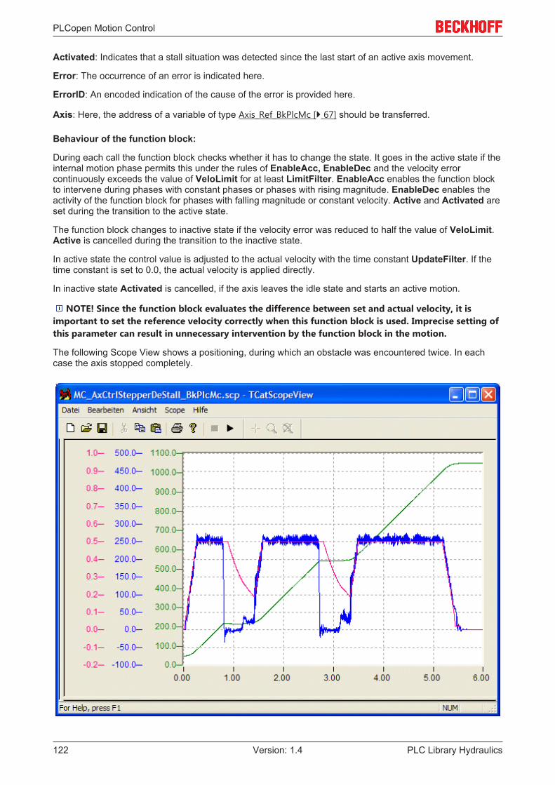
PLCopen Motion Control
PLC Library Hydraulics122 Version: 1.4
Activated: Indicates that a stall situation was detected since the last start of an active axis movement.
Error: The occurrence of an error is indicated here.
ErrorID: An encoded indication of the cause of the error is provided here.
Axis: Here, the address of a variable of type Axis_Ref_BkPlcMc [} 67] should be transferred.
Behaviour of the function block:
During each call the function block checks whether it has to change the state. It goes in the active state if theinternal motion phase permits this under the rules of EnableAcc, EnableDec and the velocity errorcontinuously exceeds the value of VeloLimit for at least LimitFilter. EnableAcc enables the function blockto intervene during phases with constant phases or phases with rising magnitude. EnableDec enables theactivity of the function block for phases with falling magnitude or constant velocity. Active and Activated areset during the transition to the active state.
The function block changes to inactive state if the velocity error was reduced to half the value of VeloLimit.Active is cancelled during the transition to the inactive state.
In active state the control value is adjusted to the actual velocity with the time constant UpdateFilter. If thetime constant is set to 0.0, the actual velocity is applied directly.
In inactive state Activated is cancelled, if the axis leaves the idle state and starts an active motion.
NOTE! Since the function block evaluates the difference between set and actual velocity, it isimportant to set the reference velocity correctly when this function block is used. Imprecise setting ofthis parameter can result in unnecessary intervention by the function block in the motion.
The following Scope View shows a positioning, during which an obstacle was encountered twice. In eachcase the axis stopped completely.

PLCopen Motion Control
PLC Library Hydraulics 123Version: 1.4
Integration of the function block in the application
A function block of this type must be called after the actual value acquisition and control value generation.The function block superimposes its response with that of the control value generator and enters it in theST_TcHydAxRtData [} 99]. The MC_AxRtFinish_BkPlcMc [} 175] function block to be positioned after thecontroller function block then considers the response automatically.
NOTE! A value greater than 0 in FirstAuxParamIdx can be used to instruct the function block to usethree consecutive values in the fCustomerData of the parameter structure as VeloLimit, LimitFilter andUpdateFilter. If the address of a suitable ARRAY[..] OF STRING() is entered in Axis.pStAxAuxLabels,the parameters are automatically assigned a name.
4.4.1.5 MC_AxRtPosPiControllerEx_BkPlcMc (ab V3.0.40)
The function block can be used as an alternative to the default position controller. It is called after theMC_AxRuntime_BkPlcMc() function block (setpoint generator and default position controller). Thisarrangement overwrites the responses of the default position controller.VAR_INPUT Reset: BOOL:=FALSE; I_Enable: BOOL:=FALSE;END_VARVAR_INOUT Axis: Axis_Ref_BkPlcMc;END_VARVAR_OUTPUT SetPos: LREAL; SetVelo: LREAL; Response: LREAL; InWindup: BOOL;END_VAR
Reset: This input deletes all internal and external controller responses.
I_Enable: This input controls the activity of the I component.
SetPos: [mm] The set position that becomes effective at the internal controller.
SetVelo: [mm/s] The set velocity that becomes effective at the internal controller.
Response: [mm/s] The controller response.
InWindup: Here, the limitation of the I component that has become active is signaled.
Axis: Here, the address of a variable of type Axis_Ref_BkPlcMc [} 67] should be transferred.
Purpose of the function block
The default position controller integrated in the MC_AxRuntime_BkPlcMc() [} 167] function block cannot meetthe control requirements of some applications, due to its simple structure. TheMC_AxRtPosPiControllerEx_BkPlcMc() function block is available for such applications. It supports thefollowing control components:
• Position P controller• Position I controller with threshold and Windup limit• Position D controller (realized as velocity P controller) with attenuation time• Condition feedback for the actual velocity

PLCopen Motion Control
PLC Library Hydraulics124 Version: 1.4
• Condition feedback for the actual acceleration• Compensation of the static effect of the condition feedback for the actual velocity
Velocity pre-control is activated after the controller. The same applies to any activated linearizations.
NOTE! The controller is enabled with V3.0.40. The extended parameters are supported by thePlcMcManager released with this version.
Structure of the controller
The component marked with an asterisk * prepares the set value for the I component of the controller whenthe setpoint generator is path-controlled. This is necessary because the set position provided by the setpointgenerator jumps to the target position when the braking distance is reached. With time-controlled setpointgenerator, the component is transparent.
NOTE! Not shown here: TRUE on Reset, or a missing controller enable of the axis deletes both the Icomponent and the controller output.
The I component has a threshold value Dx, which prevents a response to small deviations. For technicalreasons, this parameter is limited to at least 2/3 incremental weighting of the encoder. If the I component isto be inactive, set Ti to zero.
The implementation of the D component takes advantage of the fact that the differentiated set position isprovided by the setpoint generator. An actual velocity is determined by differentiating the actual position.Under this condition, the differentiation time constant Td acts as a proportionality factor. If the D componentis to be inactive, set the time constant Td to zero.
Three branches are implemented in the condition feedback:
• Velocity activation: The actual velocity is filtered and activated with a weighting factor. As it issubtracted, it has an attenuating effect. If the connection is to be inactive, set KCfb_V to zero.
• Acceleration activation: The actual velocity is differentiated, filtered and activated with a weightingfactor. As it is subtracted, it has an attenuating effect. If the connection is to be inactive, set KCfb_A tozero.

PLCopen Motion Control
PLC Library Hydraulics 125Version: 1.4
• A velocity activation generates a statically effective reduction of the velocity pre-control. In the case ofpath-controlled positioning, this generates a noticeable velocity deviation. With time-controlledpositioning, this effect is compensated, as far as possible, by the continuously active position control.This undesirable side-effect of velocity feedback is eliminated by automatic adjustment of the pre-control. Deactivating the velocity activation also deactivates this compensation.
Velocity pre-control is activated after the controller. The weighting is fixed at 1.0 when the setpoint generatoris path-controlled and cannot be reduced.
If linearization is activated, it takes place after the controller and is not shown here.
4.4.2 Drive
4.4.2.1 MC_AxRtDrive_BkPlcMc (in V3.0)
The function block performs preparation of the control value for the axis for it to be output on a hardwaremodule. To this end a function block is called depending on the value set as nDrive_Type inAxis.ST_TcHydAxParam [} 93], which takes into account the special features of the hardware module.VAR_OUTPUT Error: BOOL; ErrorID: UDINT;END_VARVAR_INOUT Axis: Axis_Ref_BkPlcMc;END_VAR
Error: The occurrence of an error is indicated here.
ErrorID: An encoded indication of the cause of the error is provided here.
Axis: Here, the address of a variable of type Axis_Ref_BkPlcMc [} 67] should be transferred.
Behaviour of the function block:
The function block investigates the axis interface that has been passed to it every time it is called. A numberof problems can be detected and reported during this process:
• If nDrive_Type in pStAxParams is set to an unacceptable value, the function block reacts with Errorand ErrorID:=dwTcHydErrCdDriveType. If the pointer pStAxRtData for the axis has been initialized, itis placed into a fault state.
• If one of the specific sub-function-blocks detects a problem, it will (if possible) place the axis into a faultstate. This error is then echoed at the outputs of the MC_AxRtDrive_BkPlcMc.
If it is possible to carry out these checks without encountering any problems, the control value for the axis isprocessed appropriately for the nDrive_Type [} 72] in Axis.ST_TcHydAxParam [} 93].
Information about the necessary linking of I/O components with the input and output structures of the axismay be found in the Knowledge Base [} 218] under FAQ #7.
If only the usual blocks (encoder, generator, finish, drive) for the axis are to be called, a block of typeMC_AxStandardBody_BkPlcMc [} 181] should be used for simplicity.
The function blocks MC_AxUtiReadRegDriveTerm_BkPlcMc [} 207] andMC_AxUtiWriteRegDriveTerm_BkPlcMc [} 215] are available for asynchronous data exchange with I/Odevices of the KL series.

PLCopen Motion Control
PLC Library Hydraulics126 Version: 1.4
iTcMc_DriveAx2000_B110A
The function block handles the evaluation of the actual values of an AX2000 servo actuator at the EtherCATfieldbus. This assumes that the connected motor is equipped with an absolute encoder. If a motor isoperated with a resolver, iTcMc_DriveAx2000_B110R should be set.
NOTE! During manual insertion or automatic detection of a drive actuator the TwinCAT SystemManager will suggest to insert an NC axis in the project and connect it with this actuator. If thisactuator is to be controlled with the hydraulic system library, it is essential to decline this suggestion.
This I/O device belongs to a group of devices, which are used for the control value output as well as actualvalue determination. The required mapping definitions overlap with those of the encoder function block anddescribed there. See also iTcMc_EncoderAX2000_B110A [} 136].
iTcMc_DriveAx2000_B110R
The function block handles the processing of the axis control value for output on an AX2000 servo drive atthe EtherCAT fieldbus.
NOTE! During manual insertion or automatic detection of a drive actuator the TwinCAT SystemManager will suggest to insert an NC axis in the project and connect it with this actuator. If thisactuator is to be controlled with the hydraulic system library, it is essential to decline this proposition.
This I/O device belongs to a group of devices, which are used for the control value output as well as actualvalue determination. The required mapping definitions overlap with those of the encoder function block anddescribed there. See also iTcMc_EncoderAx2000_B110R [} 137].
iTcMc_DriveAx2000_B200R, iTcMc_DriveAx2000_B900R
The function block handles the processing of the axis control value for output on an AX2000 servo drive atthe Beckhoff Lightbus (B200) or RtEthernet fieldbus (B900).
NOTE! During manual insertion or automatic detection of a drive actuator the TwinCAT SystemManager will suggest to insert an NC axis in the project and connect it with this actuator. If thisactuator is to be controlled with the hydraulic system library, it is essential to decline this proposition.
This I/O device belongs to a group of devices, which are used for the control value output as well as actualvalue determination. The required mapping definitions overlap with those of the encoder function block anddescribed there. See also iTcMc_EncoderAx2000_B200R [} 138].
iTcMc_DriveAx2000_B750A
The function block handles (from V3.0.26) processing of the control value of the axis for output at an AX2000servo actuator at the Sercos fieldbus. The function block handles the evaluation of the actual values of anAX2000 servo actuator at the EtherCAT fieldbus.
NOTE! During manual insertion or automatic detection of a drive actuator the TwinCAT SystemManager will suggest to insert an NC axis in the project and connect it with this actuator. If thisactuator is to be controlled with the hydraulic system library, it is essential to decline this proposition.
This I/O device belongs to a group of devices, which are used for the control value output as well as actualvalue determination. The required mapping definitions overlap with those of the encoder function block anddescribed there. See also iTcMc_EncoderAX2000_B750A [} 139].
Note a number of special features. Further information can be found in the Knowledge Base.
iTcMc_DriveAx5000_B110A, iTcMc_DriveAx5000_B110SR
The function block handles the processing of the axis control value for output on an AX5000 servo actuatorat the EtherCAT fieldbus. The function block handles the evaluation of the actual values of an AX2000 servoactuator at the EtherCAT fieldbus. If motor is operated with a resolver, iTcMc_EncoderAx5000_B110SRshould be set.
PLCopen Motion Control
PLC Library Hydraulics 127Version: 1.4
NOTE! During manual insertion or automatic detection of a drive actuator the TwinCAT SystemManager will suggest to insert an NC axis in the project and connect it with this actuator. If thisactuator is to be controlled with the hydraulic system library, it is essential to decline this suggestion.
This I/O device belongs to a group of devices, which are used for the control value output as well as actualvalue determination. The required mapping definitions overlap with those of the encoder function block anddescribed there. See also iTcMc_EncoderAX5000_B110A [} 139].
A list of successfully tested compatible devices can be found under iTcMc_EncoderAX5000_B110A [} 139].
Note a number of special characteristics. Further information can be found in the Knowledge Base.
iTcMc_DriveCoE_DS402
The function block handles the evaluation of the actual values of a servo actuator with CoE DS402 profile atthe EtherCAT fieldbus.
NOTE! During manual insertion or automatic detection of a drive actuator the TwinCAT SystemManager will suggest to insert an NC axis in the project and connect it with this actuator. If thisactuator is to be controlled with the hydraulic system library, it is essential to decline this suggestion.
This I/O device belongs to a group of devices, which are used for the control value output as well as actualvalue determination. The required mapping definitions overlap with those of the encoder function block anddescribed there. See also iTcMc_EncoderCoE_DS402A [} 141] and iTcMc_EncoderCoE_DS402SR [} 141].
A list of successfully tested compatible devices can be found under iTcMc_EncoderCoE_DS402SR [} 141].
NOTE! Currently only drives with resolver or single-turn encoders are supported.
iTcMc_Drive_CoE_DS408
The function block handles the processing of the axis control value for output to a proportional valve at theEtherCAT fieldbus. The valve must support the CiA DS408 profile.
I/O variable Interface.Variable Usesee note ST_TcPlcDeviceInput.nDacOut Output of the velocity signal.see note ST_TcPlcDeviceOutput.uiDriveCtrl Device control.see note ST_TcPlcDeviceInput.uiStatus Device statusWcState ST_TcPlcDeviceInput.wDriveWcSt
ateConnection monitoring.
InfoData.State ST_TcPlcDeviceInput.uiDriveBoxState
Monitoring of online status
InfoData.AdsAddr ST_TcPlcDeviceInput.sDrvAdsAddr
Automatic identification.
NOTE! The names of the process data exchanged with the device are specified via the XML file ofthe manufacturer.
The valve must support the following Index.SubIndex combinations.
Index Subindex Meaning1000 0 Identification1008 0 Device name (optional)1018 1 Manufacturer ID1018 2 Device type
The following list of compatible devices is naturally incomplete. It is not a recommendation but is merelyintended for information. Beckhoff cannot guarantee trouble-free operation of the listed devices. If amanufacturer or one of their devices is not listed, trouble-free operation may well be possible, but is notguaranteed.
PLCopen Motion Control
PLC Library Hydraulics128 Version: 1.4
Manufacturer Type DescriptionMoog D638Exxx Proportional valveParker DxxFP /DxxFE /TDP /TPQ Proportional valve
x: Represents a placeholder for different characters.
iTcMc_DriveIx2512_1Coil
The function block deals with processing of the axis control value for output on an IP2512 PWM fieldbusmodule.
I/O variable Interface.Variable UseData out ST_TcPlcDeviceOutput.uiDacOutA Output of the PWM factor.
iTcMc_DriveIx2512_2Coil
The function block deals with processing of the axis control value for output on an IP2512 PWM fieldbusmodule.
I/O variable Interface.Variable UseData out ST_TcPlcDeviceOutput.uiDacOutA Output of the PWM factor for coil 1.Data out ST_TcPlcDeviceOutput.uiDacOutB Output of the PWM factor for coil 2.
iTcMc_DriveEL2535
The function block prepares the control value of the axis for output on a current-controlled PWM outputterminal. This terminal provides two independent output stages and can be used for the following valvetypes:
Proportional valve with spring center position and two coils without permanent magnets:
nDrive_Type = iTcMc_DriveEL2535_2Coil
Both channels are required for one valve. The terminal cannot be used for another valve at the same time.
With this type of valve, a proportion of the full current in the directionally active coil with currentlesscountercoil is required to move the slider to the desired position. For -100% .. 0% .. +100% control, theterminal block generates the output values 0 .. 0 .. 32767 in uiDacOutA and 32767 .. 0 .. 0 in uiDacOutB.
I/O variable Interface.Variable UseChannel1.PWM Output ST_TcPlcDeviceOutput.uiDacOutA Output of the PWM factor for coil 1.Channel2.PWM Output ST_TcPlcDeviceOutput.uiDacOutB Output of the PWM factor for coil 2.
ST_TcPlcDeviceOutput.nDacOut DO NOT USE!Channel1.Status ST_TcPlcDeviceInput.uiStatus Status of the first device channelChannel2.Status ST_TcPlcDeviceInput.uiTerminalSt
ate2Status of the second devicechannel
Channel1.Control ST_TcPlcDeviceOutput.uiDriveCtrl Control of the first device channelChannel2.Control ST_TcPlcDeviceOutput.uiTerminal
Ctrl2Control of the second devicechannel
InfoData.State ST_TcPlcDeviceInput.uiDriveBoxState
Connection monitoring, conditionmonitoring.
WcState ST_TcPlcDeviceInput.wDriveWcState
Connection monitoring.
InfoData.AdsAddr ST_TcPlcDeviceInput.sDrvAdsAddr
Automatic identification,parameterization.
Proportional valve with spring end position and coil without permanent magnets:
nDrive_Type = iTcMc_DriveEL2535_1Coil

PLCopen Motion Control
PLC Library Hydraulics 129Version: 1.4
Only one channel is required here. The terminal can also be used for another valve. The I/O variables of thesecond channel must be used for this purpose.
With this type of valve, 50% of the full power supply is required to move the slider to the center position. Theterminal module generates the output values 0 .. 16384 .. 32767 for -100% .. 0% .. +100% control.
I/O variable Interface.Variable UseST_TcPlcDeviceOutput.uiDacOutA DO NOT USE!ST_TcPlcDeviceOutput.uiDacOutB DO NOT USE!
Channel1.PWM Output ST_TcPlcDeviceOutput.nDacOut Output of the PWM factor.Channel1.Status ST_TcPlcDeviceInput.uiStatus Device status
Channel1.Control ST_TcPlcDeviceOutput.uiDriveCtrl Device control.InfoData.State ST_TcPlcDeviceInput.uiDriveBoxSt
ateConnection monitoring, conditionmonitoring.
WcState ST_TcPlcDeviceInput.wDriveWcState
Connection monitoring.
InfoData.AdsAddr ST_TcPlcDeviceInput.sDrvAdsAddr
Automatic identification,parameterization.
Proportional valve with spring center position and a coil with permanent magnets:
nDrive_Type = iTcMc_DriveEL2535_1Coil
Only one channel is required here. The terminal can also be used for another valve. The I/O variables of thesecond channel must be used for this purpose.
This type of valve requires a bipolar current supply, which corresponds to the operating principle of a ±10 Vterminal. The output value generated by the terminal block is to be adjusted as follows AFTER the drivefunction block has been called by the application:
ST_TcPlcDeviceOutput.nDacOut := 2 * (ST_TcPlcDeviceOutput.nDacOut - 16384);
I/O variable Interface.Variable UseST_TcPlcDeviceOutput.uiDacOutA DO NOT USE!ST_TcPlcDeviceOutput.uiDacOutB DO NOT USE!
Channel1.PWM Output ST_TcPlcDeviceOutput.nDacOut Output of the PWM factor.Channel1.Status ST_TcPlcDeviceInput.uiStatus Device statusChannel1.Control ST_TcPlcDeviceOutput.uiDriveCtrl Device control.InfoData.State ST_TcPlcDeviceInput.uiDriveBoxSt
ateConnection monitoring, conditionmonitoring.
WcState ST_TcPlcDeviceInput.wDriveWcState
Connection monitoring.
InfoData.AdsAddr ST_TcPlcDeviceInput.sDrvAdsAddr
Automatic identification,parameterization.
iTcMc_DriveEL4132
The function block deals with processing of the axis control value for output on a ±10 V output terminal.
I/O variable Interface.Variable UseOutput ST_TcPlcDeviceOutput.nDacOut Operation: Output of the velocity
signal.InfoData.State ST_TcPlcDeviceInput.uiDriveBoxSt
ateConnection monitoring, conditionmonitoring.
WcState ST_TcPlcDeviceInput.wDriveWcState
Connection monitoring.

PLCopen Motion Control
PLC Library Hydraulics130 Version: 1.4
iTcMc_DriveEL7031
The function block deals with processing of the axis control value for output on an EL7031 stepper motoroutput stage terminal.
I/O variable Interface.Variable UseSTM Velocity.Velocity ST_TcPlcDeviceOutput.nDacOut Operation: Output of the velocity
signal.STM Control.Control ST_TcPlcDeviceOutput.uiDriveCtrl Operation: Control of the output
stage.STM Status.Status ST_TcPlcDeviceInput.uiStatus Operation: Status of the output
stage.WcState.WcState ST_TcPlcDeviceInput.wDriveWcSt
ateConnection monitoring.
InfoData.State ST_TcPlcDeviceInput.uiDriveBoxState
Connection monitoring, conditionmonitoring.
InfoData.AdsAddr ST_TcPlcDeviceInput.sDrvAdsAddr
Communication.
iTcMc_DriveEL7041
The function block deals with processing of the axis control value for output on an EL7041 stepper motoroutput stage terminal.
I/O variable Interface.Variable UseSTM Velocity.Velocity ST_TcPlcDeviceOutput.nDacOut Operation: Output of the velocity
signal.STM Control.Control ST_TcPlcDeviceOutput.uiDriveCtrl Operation: Control of the output
stage.STM Status.Status ST_TcPlcDeviceInput.uiStatus Operation: Status of the output
stage.ENC Status.Counter Value ST_TcPlcDeviceInput.uiCount Operation: Read the actual
position.ENC Status.Latch Value ST_TcPlcDeviceInput.uiLatch Operation: Reading the latch
position.ENC Status.Status ST_TcPlcDeviceInput.uiTerminalSt
ate2Operation: Status of the encoderinterface.
ENC Control.Control ST_TcPlcDeviceOutput.uiTerminalCtrl2
Operation: Control of the encoderinterface.
WcState.WcState ST_TcPlcDeviceInput.wDriveWcState
Connection monitoring.
InfoData.State ST_TcPlcDeviceInput.uiDriveBoxState
Connection monitoring, conditionmonitoring.
InfoData.AdsAddr ST_TcPlcDeviceInput.sDrvAdsAddr
Communication.
iTcMc_DriveEL7201
The function block prepares the control value of the axis for output to an EL7201 servo terminal.
This I/O device belongs to a group of devices, which are used for the control value output as well as actualvalue determination. The required mapping definitions, particularly for parameter communication, overlapwith those of the encoder function block. See also iTcMc_EncoderEL7201.

PLCopen Motion Control
PLC Library Hydraulics 131Version: 1.4
I/O variable Interface.Variable UseTarget velocity ST_TcPlcDeviceOutput.NominalVe
loOperation: Output of the velocitysignal.
Controlword ST_TcPlcDeviceOutput.uiDriveCtrl Operation: Control of the outputstage.
Position actual value ST_TcPlcDeviceInput.udiCount Operation: Read the actualposition.
WcState ST_TcPlcDeviceInput.wDriveWcState
Connection monitoring.
Statusword ST_TcPlcDeviceInput.uiStatus Operation: Status of the outputstage.
InfoData.State ST_TcPlcDeviceInput.uiDriveBoxState
Connection monitoring, conditionmonitoring.
InfoData.AdsAddr ST_TcPlcDeviceInput.sDrvAdsAddr
Communication
iTcMc_DriveKL2521
The function block deals with processing of the axis control value for output on a KL2521 pulse outputterminal.
This I/O device belongs to a group of devices, which are used for the control value output as well as actualvalue determination. The required mapping definitions, particularly for parameter communication, overlapwith those of the encoder function block. See also iTcMc_EncoderKL2521 [} 147].
I/O variable Interface.Variable UseData in ST_TcPlcDeviceInput.uiTerminalD
ataOperation: Read the actualposition.
For register communication[} 233]: Interface for read data.
Control ST_TcPlcDeviceOutput.bTerminalCtrl
Register communication
Status ST_TcPlcDeviceInput.bTerminalState
Register communication
Data out ST_TcPlcDeviceOutput.nDacOut Operation: Output of the velocitysignal.Register communication: Interfacefor written data.
iTcMc_DriveKL2531
The function block deals with processing of the axis control value for output on a KL2531 stepper motoroutput stage terminal.
This I/O device belongs to a group of devices, which are used for the control value output as well as actualvalue determination. The required mapping definitions, particularly for parameter communication, overlapwith those of the encoder function block. See also iTcMc_EncoderKL2531 [} 148].

PLCopen Motion Control
PLC Library Hydraulics132 Version: 1.4
I/O variable Interface.Variable UseVelocity ST_TcPlcDeviceOutput.nDacOut Operation: Output of the velocity
signal.
For register communication[} 233]: Interface for written data.
Position ST_TcPlcDeviceInput.uiTerminalData
Operation: Read the actualposition.For register communication:Interface for read data.
Ctrl ST_TcPlcDeviceOutput.bTerminalCtrl
Control the output stage, registercommunication.
Status ST_TcPlcDeviceInput.bTerminalState
Status of the output stage, registercommunication.
ExtStatus ST_TcPlcDeviceInput.uiTerminalState2
Diagnosis of output stage andmotor
iTcMc_DriveKL2532
The function block deals with processing of the axis control value for output on a KL2532 DC motor outputstage terminal.
I/O variable Interface.Variable UseData in ST_TcPlcDeviceInput.uiTerminalD
ataFor register communication[} 233]: Interface for read data.
Control ST_TcPlcDeviceOutput.bTerminalCtrl
Register communication.
Status ST_TcPlcDeviceInput.bTerminalState
Register communication
Data out ST_TcPlcDeviceOutput.nDacOut Register communication
iTcMc_DriveKL2535_1Coil, iTcMc_DriveKL2535_2Coil
The function block deals with processing of the axis control value for output on a KL2535 PWM output stageterminal.
I/O variable Interface.Variable UseData in ST_TcPlcDeviceInput.uiTerminalD
ataRegister communication [} 233]
Control ST_TcPlcDeviceOutput.bTerminalCtrl
Register communication.
Status ST_TcPlcDeviceInput.bTerminalState
Register communication
Data out ST_TcPlcDeviceOutput.nDacOut Register communication
iTcMc_DriveKL2541
The function block deals with processing of the axis control value for output on a KL2541 stepper motoroutput stage terminal.
This I/O device belongs to a group of devices, which are used for the control value output as well as actualvalue determination. The required mapping definitions, particularly for parameter communication, overlapwith those of the encoder function block. See also iTcMc_EncoderKL2541 [} 148].

PLCopen Motion Control
PLC Library Hydraulics 133Version: 1.4
I/O variable Interface.Variable UseVelocity ST_TcPlcDeviceOutput.nDacOut Operation: Output of the velocity
signal.
For register communication[} 233]: Interface for written data.
Position ST_TcPlcDeviceInput.uiTerminalData
Operation: Read the actualposition.For register communication:Interface for read data.
Ctrl ST_TcPlcDeviceOutput.bTerminalCtrl
Control the output stage, registercommunication.
Status ST_TcPlcDeviceInput.bTerminalState
Status of the output stage, registercommunication.
ExtCtrl ST_TcPlcDeviceOutput.uiTerminalCtrl2
Latch control during homing withthe synchronous pulse of theencoder
ExtStatus ST_TcPlcDeviceInput.uiTerminalState2
Diagnosis of output stage andmotor, latch status during homingwith the synchronous pulse of theencoder
iTcMc_DriveKL2542
The function block deals with processing of the axis control value for output on a KL2542 DC motor outputstage terminal.
This I/O device belongs to a group of devices, which are used for the control value output as well as actualvalue determination. The required mapping definitions, particularly for parameter communication, overlapwith those of the encoder function block. See also iTcMc_EncoderKL2542 [} 149].
I/O variable Interface.Variable UseData out ST_TcPlcDeviceOutput.nDacOut Operation: Output of the velocity
signal.
For register communication[} 233]: Interface for written data.
Data in ST_TcPlcDeviceInput.uiTerminalData
Operation: Read the actualposition.For register communication:Interface for read data.
Control ST_TcPlcDeviceOutput.bTerminalCtrl
Control the output stage, registercommunication.
Status ST_TcPlcDeviceInput.bTerminalState
Status of the output stage, registercommunication.
iTcMc_DriveKL4032
The function block deals with processing of the axis control value for output on a ±10 V output terminal.

PLCopen Motion Control
PLC Library Hydraulics134 Version: 1.4
I/O variable Interface.Variable UseData out ST_TcPlcDeviceOutput.nDacOut Operation: Output of the velocity
signal.
For register communication[} 233]: Interface for written data.
Control ST_TcPlcDeviceOutput.bTerminalCtrl
Register communication
Status ST_TcPlcDeviceInput.bTerminalState
Register communication
Data in ST_TcPlcDeviceOutput.uiTerminalData
Register communication: Interfacefor read data.
iTcMc_DriveLowCostStepper
The function block deals with processing of the axis control value for output on digital output terminals. Foremulation of an actual position, a pulse counter is updated, which can be evaluated with aniTcMc_EncoderLowCostStepper [} 151] encoder.
I/O variable Interface.Variable UseOutput ST_TcPlcDeviceOutput.nDigOutAp Non-inverted control of the A
phase.Output ST_TcPlcDeviceOutput.nDigOutAn Inverted control of the A phase.Output ST_TcPlcDeviceOutput.nDigOutBp Non-inverted control of the B
phase.Output ST_TcPlcDeviceOutput.nDigOutBn Inverted control of the B phase.
iTcMc_DriveLowCostInverter
The function block deals with processing of the axis control value for output on digital output terminals foroperation of a pole reversing contactor configuration or a frequency inverter with fixed frequencies. If thisdrive type is used, a number of special characteristics must be taken into account. For linking, a distinctionhas to be made between two options:
Brake, enable, direction and velocity level
After the MC_AxRtFinish_BkPlcMc [} 175] or MC_AxStandardBody_BkPlcMc [} 181]function block of the axishas been called, four decoded signals are available. In order to generate the required signals, the followingconsolidations of the direction-specific signals are required after the function block call. Sample:stAxDeviceOut.bDigOutAp:=stAxDeviceOut.bDigOutAp OR stAxDeviceOut.bDigOutBp;
stAxDeviceOut.bDigOutAn:=stAxDeviceOut.bDigOutAn OR stAxDeviceOut.bDigOutBn;
NOTE! From V3.0.11 the output of an absolute value can be activated on the valve tab. In this case,the signal consolidation shown above is applied internally.

PLCopen Motion Control
PLC Library Hydraulics 135Version: 1.4
I/O variable Interface.Variable UseOutput ST_TcPlcDeviceOutput.nDigOutAp Selection of the fixed frequency for
rapid traverse.Output ST_TcPlcDeviceOutput.nDigOutAn Selection of the fixed frequency for
slow traverse.Output ST_TcPlcDeviceOutput.bMovePos Specifies the direction of travel:
Positive.Output ST_TcPlcDeviceOutput.bMoveNeg Specifies the direction of travel:
Negative.Output ST_TcPlcDeviceOutput.bPowerOn Enabling the power stage.Output ST_TcPlcDeviceOutput.bBrakeOff Activation of the brake.Input ST_TcPlcDeviceInput.bPowerOk Status of the converter: Ready for
operation.
Brake, enable and direction-coded velocity level
I/O variable Interface.Variable UseOutput ST_TcPlcDeviceOutput.nDigOutAp Selection of the fixed frequency for
rapid traverse in positive directionof travel.
Output ST_TcPlcDeviceOutput.nDigOutAn Selection of the fixed frequency forslow traverse in positive directionof travel.
Output ST_TcPlcDeviceOutput.nDigOutBn Selection of the fixed frequency forslow traverse in negative directionof travel.
Output ST_TcPlcDeviceOutput.nDigOutBp Selection of the fixed frequency forrapid traverse in negative directionof travel.
Output ST_TcPlcDeviceOutput.bPowerOn Enabling the power stage.Output ST_TcPlcDeviceOutput.bBrakeOff Activation of the brake.Input ST_TcPlcDeviceInput.bPowerOk Status of the converter: Ready for
operation.
iTcMc_DriveM2400_Dn
The function block performs preparation of the control value for the axis so that it can be output on one of thefour channels of a ±10 V M2400 output box.
I/O variable Interface.Variable UseData out ST_TcPlcDeviceOutput.nDacOut Operation: Output of the velocity
signal.
4.4.3 Encoder
4.4.3.1 MC_AxRtEncoder_BkPlcMc (from V3.0)
This function block determines the actual position of the axis from the input information of a hardwaremodule. To this end a function block is called depending on the value set as nEnc_Type inAxis.ST_TcHydAxParam [} 93], which takes into account the special features of the hardware module.
PLCopen Motion Control
PLC Library Hydraulics136 Version: 1.4
VAR_OUTPUT Error: BOOL; ErrorID: UDINT;END_VARVAR_INOUT Axis: Axis_Ref_BkPlcMc;END_VAR
Error: The occurrence of an error is indicated here.
ErrorID: An encoded indication of the cause of the error is provided here.
Axis: Here, the address of a variable of type Axis_Ref_BkPlcMc [} 67] should be transferred.
Behavior of the function block
The function block investigates the axis interface that has been passed to it every time it is called. A numberof problems can be detected and reported during this process:
• If nEnc_Type in pStAxParams is set to an unacceptable value, the function block responds with Errorand ErrorID:=dwTcHydErrCdEncType. The axis is set to an error state.
• If one of the specific sub-function-blocks detects a problem, it will (if possible) place the axis into a faultstate. This error is then echoed at the outputs of the MC_AxRtEncoder_BkPlcMc.
If it is possible to carry out these checks without encountering any problems, the actual value of the axis isdetermined by calling a type-specific function block corresponding to the nEnc_Type [} 75] inAxis.ST_TcHydAxParam [} 93].
Information about the necessary linking of I/O components with the input and output structures of the axismay be found in the Knowledge Base under FAQ #4 [} 222].
If only the usual blocks (encoder, generator, finish, drive) for the axis are to be called, a block of typeMC_AxStandardBody_BkPlcMc [} 181] should be used for simplicity.
The function blocks MC_AxUtiReadRegEncTerm_BkPlcMc [} 208] and MC_AxUtiWriteRegEncTerm_BkPlcMc[} 216] are available for asynchronous data exchange with I/O devices of the KL series.
iTcMc_EncoderAx2000_B110A
The function block handles the evaluation of the actual values of an AX2000 servo actuator at the EtherCATfieldbus. This assumes that the connected motor is equipped with an absolute encoder. If a motor isoperated with a resolver, iTcMc_EncoderAx2000_B110R should be set.
NOTE! During manual insertion or automatic detection of a drive actuator the TwinCAT SystemManager will suggest to insert an NC axis in the project and connect it with this actuator. If thisactuator is to be controlled with the hydraulic system library, it is essential to decline this proposition.
This I/O device belongs to a group of devices, which are used for the control value output as well as actualvalue determination. The required mapping definitions overlap with those of the drive function block. Seealso iTcMc_DriveAX2000_B110R [} 126].

PLCopen Motion Control
PLC Library Hydraulics 137Version: 1.4
I/O variable Interface.Variable UsePosition actual value ST_TcPlcDeviceInput.ActualPos[0.
.1]Determines the actual position.
Status word ST_TcPlcDeviceInput.uiStatus Device status, encoder emulation.Control word ST_TcPlcDeviceOutput.uiDriveCtrl Device control.Velocity demand value ST_TcPlcDeviceOutput.NominalVe
loOutput of the velocity control value.
WcState (see note) ST_TcPlcDeviceInput.wEncWcState
Connection monitoring for actualvalue acquisition.
WcState ST_TcPlcDeviceInput.wDriveWcState
Connection monitoring for thedrive.
InfoData.State ST_TcPlcDeviceInput.uiDriveBoxState
Monitoring of online status
InfoData.AdsAddr (see note) ST_TcPlcDeviceInput.sEncAdsAddr
Parameter communication.
InfoData.AdsAddr ST_TcPlcDeviceInput.sDrvAdsAddr
Control of real-time status,parameter communication.
Chn0 (see note) ST_TcPlcDeviceInput.nEncAdsChannel
Parameter communication.
Chn0 ST_TcPlcDeviceInput.nDrvAdsChannel
Control of real-time status,parameter communication.
Output (on a DO terminal) ST_TcPlcDeviceOutput.PowerOn Optional control of the mainscontactor. A digital output terminalis required for this purpose.
Input (on a DI terminal) ST_TcPlcDeviceInput.PowerOk Optional evaluation of the mainscontactor. A digital input terminal isrequired for this purpose.
NOTE! In order to simplify the establishment of the I/O link, the linking ofST_TcPlcDeviceInput.sEncAdsAddr, ST_TcPlcDeviceInput.nEncAdsChannel andST_TcPlcDeviceInput.wEncWcState can be avoided, if the actual value acquisition takes place via thesame device, as usual. In this case, the function blocks for parameter communication and encoderevaluation use the corresponding variables of the drive link.
iTcMc_EncoderAx2000_B110R
The function block handles the evaluation of the actual values of an AX2000 servo actuator at the EtherCATfieldbus. This assumes that the connected motor is equipped with a resolver. If a motor is operated with anabsolute encoder, iTcMc_EncoderAx2000_B110A must be set.
NOTE! During manual insertion or automatic detection of a drive actuator the TwinCAT SystemManager will suggest to insert an NC axis in the project and connect it with this actuator. If thisactuator is to be controlled with the hydraulic system library, it is essential to decline this proposition.
This I/O device belongs to a group of devices, which are used for the control value output as well as actualvalue determination. The required mapping definitions overlap with those of the drive function block. Seealso iTcMc_DriveAX2000_B110R [} 126].

PLCopen Motion Control
PLC Library Hydraulics138 Version: 1.4
I/O variable Interface.Variable UsePosition actual value ST_TcPlcDeviceInput.ActualPos[0.
.1]Determines the actual position.
Status word ST_TcPlcDeviceInput.uiStatus Device status, encoder emulation.Control word ST_TcPlcDeviceOutput.uiDriveCtrl Device control.Velocity demand value ST_TcPlcDeviceOutput.NominalVe
loOutput of the velocity control value.
WcState (see note) ST_TcPlcDeviceInput.wEncWcState
Connection monitoring for actualvalue acquisition.
WcState ST_TcPlcDeviceInput.wDriveWcState
Connection monitoring for thedrive.
uiDriveBoxState ST_TcPlcDeviceInput.InfoData.State
Monitoring of online status
InfoData.AdsAddr (see note) ST_TcPlcDeviceInput.sEncAdsAddr
Parameter communication.
InfoData.AdsAddr ST_TcPlcDeviceInput.sDrvAdsAddr
Parameter communication.
Chn0 (see note) ST_TcPlcDeviceInput.nEncAdsChannel
Parameter communication.
Chn0 ST_TcPlcDeviceInput.nDrvAdsChannel
Parameter communication.
Output (on a DO terminal) ST_TcPlcDeviceOutput.PowerOn Optional control of the mainscontactor. A digital output terminalis required for this purpose.
Input (on a DI terminal) ST_TcPlcDeviceInput.PowerOk Optional evaluation of the mainscontactor. A digital input terminal isrequired for this purpose.
NOTE! In order to simplify the establishment of the I/O link, the linking ofST_TcPlcDeviceInput.sEncAdsAddr, ST_TcPlcDeviceInput.nEncAdsChannel andST_TcPlcDeviceInput.wEncWcState can be avoided, if the actual value acquisition takes place via thesame device, as usual. In this case, the function blocks for parameter communication and encoderevaluation use the corresponding variables of the drive link.
iTcMc_EncoderAx2000_B200R, iTcMc_EncoderAx2000_B900R
NOTE! During manual insertion or automatic detection of a drive actuator the TwinCAT SystemManager will suggest to insert an NC axis in the project and connect it with this actuator. If thisactuator is to be controlled with the hydraulic system library, it is essential to decline this proposition.
The function block deals with evaluation of the actual values of an AX2000 servo actuator with Lightbus(B200) or RealtimeEthernet (B900).
This I/O device belongs to a group of devices, which are used for the control value output as well as actualvalue determination. The required mapping definitions overlap with those of the drive function block. Seealso iTcMc_DriveAX2000_B200R [} 126].

PLCopen Motion Control
PLC Library Hydraulics 139Version: 1.4
I/O variable Interface.Variable UseActualPos[0..1] ST_TcPlcDeviceInput.ActualPos[0.
.1]Determines the actual position.
DriveError ST_TcPlcDeviceInput.DriveError Device status.DriveState[0..3] ST_TcPlcDeviceInput.DriveState[0.
.3]Device status.
BoxState ST_TcPlcDeviceInput.uiDriveBoxState
Connection monitoring.
DriveCtrl0 ST_TcPlcDeviceOutput.DriveCtrl[0] Device control.DriveCtrl1 ST_TcPlcDeviceOutput.DriveCtrl[1] Device control.DriveCtrl2 ST_TcPlcDeviceOutput.DriveCtrl[2] Device control.DriveCtrl3 ST_TcPlcDeviceOutput.DriveCtrl[3] Device control.NominalVelo ST_TcPlcDeviceOutput.NominalVe
loOutput of the velocity control value.
Output (on a DO terminal) ST_TcPlcDeviceOutput.PowerOn Optional control of the mainscontactor. A digital output terminalis required for this purpose.
Input (on a DI terminal) ST_TcPlcDeviceInput.PowerOk Optional evaluation of the mainscontactor. A digital input terminal isrequired for this purpose.
iTcMc_EncoderAx2000_B750A
The function block handles (from V3.0.26) the evaluation of the actual values of an AX2000 servo actuator atthe Sercos fieldbus. The function block handles the evaluation of the actual values of an AX2000 servoactuator at the EtherCAT fieldbus.
NOTE! During manual insertion or automatic detection of a drive actuator the TwinCAT SystemManager will suggest to insert an NC axis in the project and connect it with this actuator. If thisactuator is to be controlled with the hydraulic system library, it is essential to decline this suggestion.
This I/O device belongs to a group of devices, which are used for the control value output as well as actualvalue determination. The required mapping definitions overlap with those of the drive function block. Seealso iTcMc_DriveAX2000_B750A [} 126].
I/O variable Interface.Variable UseDrive status word ST_TcPlcDeviceInput.uiStatus Device status.Actual position value encoder 1 ST_TcPlcDeviceInput.udiCount Determines the actual position.Master control word ST_TcPlcDeviceOutput.uiDriveCtrl Device control.Velocity command value ST_TcPlcDeviceOutput.NominalVe
loOutput of the velocity control value.
SystemStatus (from Sercosmaster)
ST_TcPlcDeviceInput.uiDriveBoxState
Monitoring of the Sercos phase.Note: This variable is provided bythe Sercos master (e.g. FC7501).
Output (on a DO terminal) ST_TcPlcDeviceOutput.PowerOn Optional control of the mainscontactor. A digital output terminalis required for this purpose.
Input (on a DI terminal) ST_TcPlcDeviceInput.PowerOk Optional evaluation of the mainscontactor. A digital input terminal isrequired for this purpose.
Note a number of special characteristics. Further information can be found in the Knowledge Base [} 218].
iTcMc_EncoderAx5000_B110A, iTcMc_EncoderAx5000_B110SR
The function block handles the evaluation of the actual values of an AX5000 servo actuator at the EtherCATfieldbus. This assumes that the connected motor is equipped with an absolute encoder. If a motor isoperated with a resolver, iTcMc_EncoderAx5000_B110SR should be set.
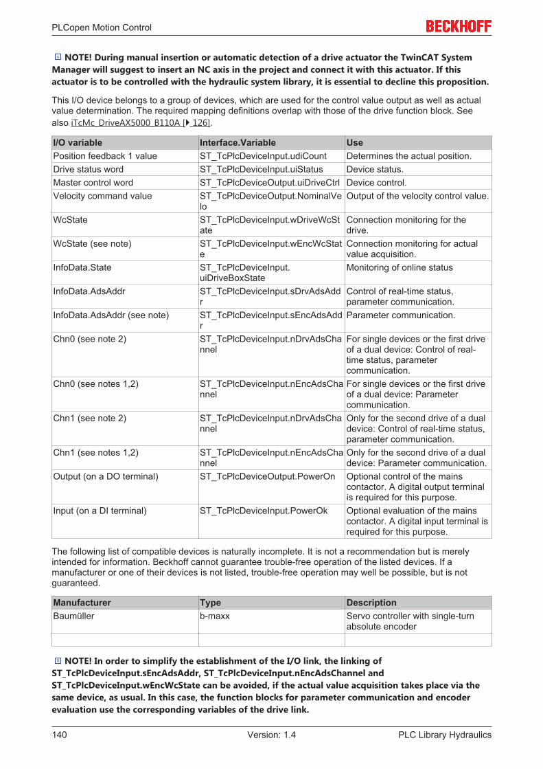
PLCopen Motion Control
PLC Library Hydraulics140 Version: 1.4
NOTE! During manual insertion or automatic detection of a drive actuator the TwinCAT SystemManager will suggest to insert an NC axis in the project and connect it with this actuator. If thisactuator is to be controlled with the hydraulic system library, it is essential to decline this proposition.
This I/O device belongs to a group of devices, which are used for the control value output as well as actualvalue determination. The required mapping definitions overlap with those of the drive function block. Seealso iTcMc_DriveAX5000_B110A [} 126].
I/O variable Interface.Variable UsePosition feedback 1 value ST_TcPlcDeviceInput.udiCount Determines the actual position.Drive status word ST_TcPlcDeviceInput.uiStatus Device status.Master control word ST_TcPlcDeviceOutput.uiDriveCtrl Device control.Velocity command value ST_TcPlcDeviceOutput.NominalVe
loOutput of the velocity control value.
WcState ST_TcPlcDeviceInput.wDriveWcState
Connection monitoring for thedrive.
WcState (see note) ST_TcPlcDeviceInput.wEncWcState
Connection monitoring for actualvalue acquisition.
InfoData.State ST_TcPlcDeviceInput.uiDriveBoxState
Monitoring of online status
InfoData.AdsAddr ST_TcPlcDeviceInput.sDrvAdsAddr
Control of real-time status,parameter communication.
InfoData.AdsAddr (see note) ST_TcPlcDeviceInput.sEncAdsAddr
Parameter communication.
Chn0 (see note 2) ST_TcPlcDeviceInput.nDrvAdsChannel
For single devices or the first driveof a dual device: Control of real-time status, parametercommunication.
Chn0 (see notes 1,2) ST_TcPlcDeviceInput.nEncAdsChannel
For single devices or the first driveof a dual device: Parametercommunication.
Chn1 (see note 2) ST_TcPlcDeviceInput.nDrvAdsChannel
Only for the second drive of a dualdevice: Control of real-time status,parameter communication.
Chn1 (see notes 1,2) ST_TcPlcDeviceInput.nEncAdsChannel
Only for the second drive of a dualdevice: Parameter communication.
Output (on a DO terminal) ST_TcPlcDeviceOutput.PowerOn Optional control of the mainscontactor. A digital output terminalis required for this purpose.
Input (on a DI terminal) ST_TcPlcDeviceInput.PowerOk Optional evaluation of the mainscontactor. A digital input terminal isrequired for this purpose.
The following list of compatible devices is naturally incomplete. It is not a recommendation but is merelyintended for information. Beckhoff cannot guarantee trouble-free operation of the listed devices. If amanufacturer or one of their devices is not listed, trouble-free operation may well be possible, but is notguaranteed.
Manufacturer Type DescriptionBaumüller b-maxx Servo controller with single-turn
absolute encoder
NOTE! In order to simplify the establishment of the I/O link, the linking ofST_TcPlcDeviceInput.sEncAdsAddr, ST_TcPlcDeviceInput.nEncAdsChannel andST_TcPlcDeviceInput.wEncWcState can be avoided, if the actual value acquisition takes place via thesame device, as usual. In this case, the function blocks for parameter communication and encoderevaluation use the corresponding variables of the drive link.
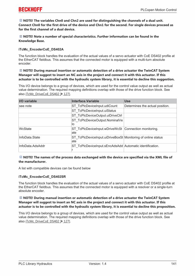
PLCopen Motion Control
PLC Library Hydraulics 141Version: 1.4
NOTE! The variables Chn0 and Chn2 are used for distinguishing the channels of a dual unit.Connect Chn0 for the first drive of the device and Chn1 for the second. For single devices proceed asfor the first channel of a dual device.
NOTE! Note a number of special characteristics. Further information can be found in theKnowledge Base.
iTcMc_EncoderCoE_DS402A
The function block handles the evaluation of the actual values of a servo actuator with CoE DS402 profile atthe EtherCAT fieldbus. This assumes that the connected motor is equipped with a multi-turn absoluteencoder.
NOTE! During manual insertion or automatic detection of a drive actuator the TwinCAT SystemManager will suggest to insert an NC axis in the project and connect it with this actuator. If thisactuator is to be controlled with the hydraulic system library, it is essential to decline this suggestion.
This I/O device belongs to a group of devices, which are used for the control value output as well as actualvalue determination. The required mapping definitions overlap with those of the drive function block. Seealso iTcMc_DriveCoE_DS402 [} 127].
I/O variable Interface.Variable Usesee note ST_TcPlcDeviceInput.udiCount Determines the actual position.
ST_TcPlcDeviceInput.uiStatusST_TcPlcDeviceOutput.uiDriveCtrlST_TcPlcDeviceOutput.NominalVelo
WcState ST_TcPlcDeviceInput.wDriveWcState
Connection monitoring.
InfoData.State ST_TcPlcDeviceInput.uiDriveBoxState
Monitoring of online status
InfoData.AdsAddr ST_TcPlcDeviceInput.sEncAdsAddr
Automatic identification.
NOTE! The names of the process data exchanged with the device are specified via the XML file ofthe manufacturer.
A list with compatible devices can be found below
iTcMc_EncoderCoE_DS402SR
The function block handles the evaluation of the actual values of a servo actuator with CoE DS402 profile atthe EtherCAT fieldbus. This assumes that the connected motor is equipped with a resolver or a single-turnabsolute encoder.
NOTE! During manual insertion or automatic detection of a drive actuator the TwinCAT SystemManager will suggest to insert an NC axis in the project and connect it with this actuator. If thisactuator is to be controlled with the hydraulic system library, it is essential to decline this proposition.
This I/O device belongs to a group of devices, which are used for the control value output as well as actualvalue determination. The required mapping definitions overlap with those of the drive function block. Seealso iTcMc_DriveCoE_DS402 [} 127].

PLCopen Motion Control
PLC Library Hydraulics142 Version: 1.4
I/O variable Interface.Variable Usesee note ST_TcPlcDeviceInput.udiCount Determines the actual position.
ST_TcPlcDeviceInput.uiStatusST_TcPlcDeviceOutput.uiDriveCtrlST_TcPlcDeviceOutput.NominalVelo
WcState ST_TcPlcDeviceInput.wDriveWcState
Connection monitoring.
InfoData.State ST_TcPlcDeviceInput.uiDriveBoxState
Monitoring of online status
InfoData.AdsAddr ST_TcPlcDeviceInput.sEncAdsAddr
Automatic identification.
NOTE! The names of the process data exchanged with the device are specified via the XML file ofthe manufacturer.
The encoder must support the following Index.SubIndex combinations.
Index Subindex Meaning1000 0 Identification1008 0 Device name (optional)1018 1 Manufacturer ID1018 2 Device type6080 0 Maximum speed in RPM (optional;
if this object is not supported, thereference speed must be enteredmanually).
608F 1 Number of encoder increments permotor revolution.
6090 1 Number of increments per motorrevolution used for control valueoutput.
The following list of compatible devices is naturally incomplete. It is not a recommendation but is merelyintended for information. Beckhoff cannot guarantee trouble-free operation of the listed devices. If amanufacturer or one of their devices is not listed, trouble-free operation may well be possible, but is notguaranteed.
Manufacturer Type DescriptionLTi DRiVES GmbH Servo controller with single-turn
absolute encoder
iTcMc_EncoderCoE_DS406
The function block handles the evaluation of encoders with direct EtherCAT connection. The encoder mustsupport the CiA DS406 profile.

PLCopen Motion Control
PLC Library Hydraulics 143Version: 1.4
I/O variable Interface.Variable Usesee note ST_TcPlcDeviceInput.udiCount Determines the actual position.see notes ST_TcPlcDeviceInput.wEncDevSta
teMonitoring the device status.
WcState ST_TcPlcDeviceInput.wEncWcState
Connection monitoring.
InfoData.State ST_TcPlcDeviceInput.uiEncBoxState
Monitoring of online status.
InfoData.AdsAddr ST_TcPlcDeviceInput.sEncAdsAddr
Automatic identification.
NOTE! The names of the process data exchanged with the device are specified via the XML file ofthe manufacturer.
NOTE! Monitoring of the device status is not guaranteed for all devices from all manufacturers. Forsome devices an 8-bit status is provided. This kind of information should be mapped on the lower 8bits of the wEncDevState element.
The encoder must support the following Index.SubIndex combinations.
Index Subindex Meaning1000 0 Identification1008 0 Device name (optional)1018 1 Manufacturer ID1018 2 Device type6001 0 Rotational encoders: increments
per revolution (obligatory)6002 0 Rotational encoders: Total counting
range (option A, alternatively: index6502)Linear encoders: Total countingrange (obligatory)
6005 1 Linear encoders: Resolution(option A, alternatively: index 6501)
6501 0 Linear encoders: Resolution(option B, alternatively: index 6005)
6502 0 Rotational encoders: Number ofcounted revolutions (option B,alternatively: index 6002)
650A 2 Linear encoders: lower limit of theintended working area (option)
650B 3 Linear encoders: upper limit of theintended working area (option)
The following list of compatible devices is naturally incomplete. It is not a recommendation but is merelyintended for information. Beckhoff cannot guarantee trouble-free operation of the listed devices. If amanufacturer or one of their devices is not listed, trouble-free operation may well be possible, but is notguaranteed.
Certain parameters can be determined automatically, depending on the support of the listed objects. Thisapplies to the counting range, the overflow detection and (for linear encoders) the resolution. If therespective objects are not provided or not in a supported combination, this is not possible. In such a case,operation may be possible. However, the parameters must then be set manually during commissioning.

PLCopen Motion Control
PLC Library Hydraulics144 Version: 1.4
Manufacturer Type DescriptionFritz Kübler GmbH 58x8 Multi-turn absolute encoder.IVO GmbH & Co. KG GXMMW_H Multi-turn absolute encoder.MTS Temposonics R Linear absolute encoder.TR Electronic GmbH: LMP Linear absolute encoder.TWK-Electronic GmbH CRKxx12R12C1xx Multi-turn absolute encoder.
iTcMc_EncoderDigCam
The function block handles the evaluation of four digital inputs as position cams.
I/O variable Interface.Variable UseInput ST_TcPlcDeviceInput.bDigCamPP Determines the actual position:
Positive target cam.Input ST_TcPlcDeviceInput.bDigCamP Determines the actual position:
Positive brake cam.Input ST_TcPlcDeviceInput.bDigCamM Determines the actual position:
Negative brake cam.Input ST_TcPlcDeviceInput.bDigCamMM Determines the actual position:
Negative target cam.
iTcMc_EncoderDigIncrement
The function block handles the evaluation of two digital inputs for the emulation of an incremental encoderevaluation.
I/O variable Interface.Variable UseInput ST_TcPlcDeviceInput.bDigInA Determines the actual position.Input ST_TcPlcDeviceInput.bDigInB Determines the actual position.
iTcMc_EncoderEL3102
The function block handles the evaluation of data from an EL3102 analog input terminal.
I/O variable Interface.Variable UseValue ST_TcPlcDeviceInput.uiCount Read the actual position.InfoData.AdsAddr ST_TcPlcDeviceInput.sEncAdsAdd
rOptional: Address information forparameter communication via CoE.
InfoData.State ST_TcPlcDeviceInput.uiEncBoxState
Connection monitoring, conditionmonitoring.
WcState ST_TcPlcDeviceInput.wEncWcState
Connection monitoring.
iTcMc_EncoderEL3142
The function block handles the evaluation of data from an EL3142 analog input terminal. The mapping issimilar to the interface-compatible EL3102.
iTcMc_EncoderEL3162
The function block handles the evaluation of data from an EL3162 analog input terminal. The mapping issimilar to the interface-compatible EL3102.
iTcMc_EncoderEL3255
The function block handles the evaluation of data from an EL3255 analog input terminal.
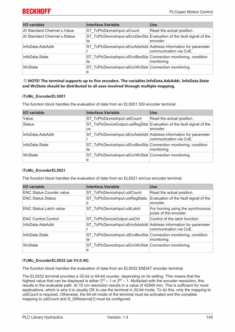
PLCopen Motion Control
PLC Library Hydraulics 145Version: 1.4
I/O variable Interface.Variable UseAI Standard Channel x.Value ST_TcPlcDeviceInput.uiCount Read the actual position.AI Standard Channel x.Status ST_TcPlcDeviceInput.wEncDevSta
teEvaluation of the fault signal of theencoder.
InfoData.AdsAddr ST_TcPlcDeviceInput.sEncAdsAddr
Address information for parametercommunication via CoE.
InfoData.State ST_TcPlcDeviceInput.uiEncBoxState
Connection monitoring, conditionmonitoring.
WcState ST_TcPlcDeviceInput.wEncWcState
Connection monitoring.
NOTE! The terminal supports up to five encoders. The variables InfoData.AdsAddr, InfoData.Stateand WcState should be distributed to all axes involved through multiple mapping.
iTcMc_EncoderEL5001
The function block handles the evaluation of data from an EL5001 SSI encoder terminal.
I/O variable Interface.Variable UseValue ST_TcPlcDeviceInput.udiCount Read the actual position.Status ST_TcPlcDeviceOutput.usiRegStat
usEvaluation of the fault signal of theencoder.
InfoData.AdsAddr ST_TcPlcDeviceInput.sEncAdsAddr
Address information for parametercommunication via CoE.
InfoData.State ST_TcPlcDeviceInput.uiEncBoxState
Connection monitoring, conditionmonitoring.
WcState ST_TcPlcDeviceInput.wEncWcState
Connection monitoring.
iTcMc_EncoderEL5021
The function block handles the evaluation of data from an EL5021 sin/cos encoder terminal.
I/O variable Interface.Variable UseENC Status.Counter value ST_TcPlcDeviceInput.udiCount Read the actual position.ENC Status.Status ST_TcPlcDeviceInput.usiRegStatu
sEvaluation of the fault signal of theencoder.
ENC Status.Latch value ST_TcPlcDeviceInput.udiLatch For homing using the synchronouspulse of the encoder.
ENC Control.Control ST_TcPlcDeviceOutput.usiCtrl Control of the latch function.InfoData.AdsAddr ST_TcPlcDeviceInput.sEncAdsAdd
rAddress information for parametercommunication via CoE.
InfoData.State ST_TcPlcDeviceInput.uiEncBoxState
Connection monitoring, conditionmonitoring.
WcState ST_TcPlcDeviceInput.wEncWcState
Connection monitoring.
iTcMc_EncoderEL5032 (ab V3.0.40)
The function block handles the evaluation of data from an EL5032 ENDAT encoder terminal.
The EL5032 terminal provides a 32-bit or 64-bit counter, depending on its setting. This means that thehighest value that can be displayed is either 232 – 1 or 264 – 1. Multiplied with the encoder resolution, thisresults in the evaluable path. At 10 nm resolution results in a value of 42949 mm. This is sufficient for mostapplications, which is why it is usually OK to use the terminal in 32-bit mode. To do this, only the mapping toudiCount is required. Otherwise, the 64-bit mode of the terminal must be activated and the completemapping to udiCount and S_DiReserve[1] must be configured.

PLCopen Motion Control
PLC Library Hydraulics146 Version: 1.4
Note
Note the supply voltageTo prevent damage to the connected device, check the supply voltage set in the EL5032before connecting the device.
When a fieldbus is started and an axis error is reset, certain parameters of the connected device are read.The device type is included in the logging. Only absolute linear scales and absolute multi-turn encoders areaccepted. With linear scales, the resolution is automatically updated in the encoder weighting andinterpolation.
I/O variable Interface.Variable UsePosition (DWORD or lower part ofULINT)
ST_TcPlcDeviceInput.udiCount Read the actual position.
Position (upper part of ULINT) ST_TcPlcDeviceInput.S_DiReserve[1]
Optional: Reading of the actualposition under TC2.
Position (upper part of ULINT) ST_TcPlcDeviceInput.udiLatch Optional: Reading of the actualposition under TC3.
Status ST_TcPlcDeviceInput.uiEncDevState
Evaluation of the fault signal of theencoder.
InfoData.AdsAddr ST_TcPlcDeviceInput.sEncAdsAddr
Address information for parametercommunication via CoE.
InfoData.State ST_TcPlcDeviceInput.uiEncBoxState
Connection monitoring, conditionmonitoring.
WcState ST_TcPlcDeviceInput.wEncWcState
Connection monitoring.
iTcMc_EncoderEL5101
The function block handles the evaluation of data from an EL5101 incremental encoder terminal.
I/O variable Interface.Variable UseValue ST_TcPlcDeviceInput.uiCount Operation: Read the actual
position.Latch ST_TcPlcDeviceInput.uiLatch For homing using the synchronous
pulse of the encoder.Ctrl ST_TcPlcDeviceOutput.usiCtrl Control of the latch function etc.Status ST_TcPlcDeviceInput.usiStatus Status of the encoder, of the latch
function.InfoData.AdsAddr ST_TcPlcDeviceInput.sEncAdsAdd
rAddress information for parametercommunication via CoE.
InfoData.State ST_TcPlcDeviceInput.uiEncBoxState
Connection monitoring, conditionmonitoring.
WcState ST_TcPlcDeviceInput.wEncWcState
Connection monitoring.
iTcMc_EncoderEL5111
The function block handles the evaluation of data from an EL5111 incremental encoder terminal.

PLCopen Motion Control
PLC Library Hydraulics 147Version: 1.4
I/O variable Interface.Variable UseValue ST_TcPlcDeviceInput.uiCount Operation: Read the actual
position.Latch ST_TcPlcDeviceInput.uiLatch For homing using the synchronous
pulse of the encoder.Ctrl ST_TcPlcDeviceOutput.usiCtrl Control of the latch function etc.Status ST_TcPlcDeviceInput.usiStatus Status of the encoder, of the latch
function.InfoData.AdsAddr ST_TcPlcDeviceInput.sEncAdsAdd
rAddress information for parametercommunication via CoE.
InfoData.State ST_TcPlcDeviceInput.uiEncBoxState
Connection monitoring, conditionmonitoring.
WcState ST_TcPlcDeviceInput.wEncWcState
Connection monitoring.
iTcMc_EncoderEL7041
The function block handles the evaluation of data from an EL7041 stepper motor output terminal.
This I/O device belongs to a group of devices, which are used for the control value output as well as actualvalue determination. The required mapping definitions, particularly for parameter communication, overlapwith those of the drive function block. See also iTcMc_DriveEL7041 [} 130].
iTcMc_EncoderEL7201
The function block handles the evaluation of data from an EL7201 servo output terminal.
This I/O device belongs to a group of devices, which are used for the control value output as well as actualvalue determination. The required mapping definitions, particularly for parameter communication, overlapwith those of the drive function block. See also iTcMc_DriveEL7201.
iTcMc_EncoderIx5009
The function block handles the evaluation of data from an IP5009 SSI encoder box.
I/O variable Interface.Variable UsePZDL_RegDaten ST_TcPlcDeviceInput.uiPZDL_Reg
DatenOperation: Read the actualposition.
For register communication[} 233]: Interface for read data.
PZDH ST_TcPlcDeviceInput.uiPZDH Read the actual position.RegStatus ST_TcPlcDeviceInput.usiRegStatu
sMiscellaneous status information.
iTcMc_EncoderKL2521
The function block handles the evaluation of data from a KL2521 pulse output terminal. The output pulsesare counted and used for an encoder emulation.
This I/O device belongs to a group of devices, which are used for the control value output as well as actualvalue determination. The required mapping definitions, particularly for parameter communication, overlapwith those of the drive function block. See also iTcMc_DriveKL2521 [} 131].

PLCopen Motion Control
PLC Library Hydraulics148 Version: 1.4
I/O variable Interface.Variable UseData in ST_TcPlcDeviceInput.uiTerminalD
ataOperation: Read the actualposition.
For register communication[} 233]: Interface for read data.
Control ST_TcPlcDeviceOutput.bTerminalCtrl
Register communication
Status ST_TcPlcDeviceInput.bTerminalState
Register communication
Data out ST_TcPlcDeviceOutput.nDacOut Operation: Output of the velocitysignal.Register communication: Interfacefor written data.
iTcMc_EncoderKL2531
The function block handles the evaluation of data from a KL2531 pulse output terminal. The output pulsesare counted and used for an encoder emulation.
This I/O device belongs to a group of devices, which are used for the control value output as well as actualvalue determination. The required mapping definitions, particularly for parameter communication, overlapwith those of the drive function block. See also iTcMc_DriveKL2531 [} 131].
I/O variable Interface.Variable UseVelocity ST_TcPlcDeviceOutput.nDacOut Operation: Output of the velocity
signal.
For register communication[} 233]: Interface for written data.
Position ST_TcPlcDeviceInput.uiTerminalData
Operation: Read the actualposition.For register communication:Interface for read data.
Ctrl ST_TcPlcDeviceOutput.bTerminalCtrl
Control the output stage, registercommunication.
Status ST_TcPlcDeviceInput.bTerminalState
Status of the output stage, registercommunication.
ExtStatus ST_TcPlcDeviceInput.uiTerminalState2
Diagnosis of output stage andmotor
iTcMc_EncoderKL2541
The function block handles the evaluation of data from a KL2541 pulse output terminal. The output pulsesare counted and used for an encoder emulation.
This I/O device belongs to a group of devices, which are used for the control value output as well as actualvalue determination. The required mapping definitions, particularly for parameter communication, overlapwith those of the drive function block. See also iTcMc_DriveKL2541 [} 132].

PLCopen Motion Control
PLC Library Hydraulics 149Version: 1.4
I/O variable Interface.Variable UseVelocity ST_TcPlcDeviceOutput.nDacOut Operation: Output of the velocity
signal.
For register communication[} 233]: Interface for written data.
Position ST_TcPlcDeviceInput.uiTerminalData
Operation: Read the actualposition.For register communication:Interface for read data.
Ctrl ST_TcPlcDeviceOutput.bTerminalCtrl
Control the output stage, registercommunication.
Status ST_TcPlcDeviceInput.bTerminalState
Status of the output stage, registercommunication.
ExtCtrl ST_TcPlcDeviceOutput.uiTerminalCtrl2
Latch control during homing withthe synchronous pulse of theencoder
ExtStatus ST_TcPlcDeviceInput.uiTerminalState2
Diagnosis of output stage andmotor, latch status during homingwith the synchronous pulse of theencoder
iTcMc_EncoderKL2542
The function block handles the evaluation of data from a KL2542 motor output stage terminal.
This I/O device belongs to a group of devices, which are used for the control value output as well as actualvalue determination. The required mapping definitions, particularly for parameter communication, overlapwith those of the drive function block. See also iTcMc_DriveKL2542 [} 133].
I/O variable Interface.Variable UseData out ST_TcPlcDeviceOutput.nDacOut Operation: Output of the velocity
signal.
For register communication[} 233]: Interface for written data.
Data in ST_TcPlcDeviceInput.uiTerminalData
Operation: Read the actualposition.For register communication:Interface for read data.
Control ST_TcPlcDeviceOutput.bTerminalCtrl
Control the output stage, registercommunication.
Status ST_TcPlcDeviceInput.bTerminalState
Status of the output stage, registercommunication.
iTcMc_EncoderKL3002
The function block handles the evaluation of data from a KL3002 analog input terminal.
I/O variable Interface.Variable UseData in ST_TcPlcDeviceInput.uiCount Read the actual position.Ctrl ST_TcPlcDeviceOutput.usiCtrl Register communication [} 233]Status ST_TcPlcDeviceInput.usiStatus Register communication.
iTcMc_EncoderKL3042
The function block handles the evaluation of data from a KL3042 analog input terminal.
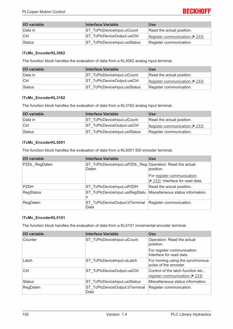
PLCopen Motion Control
PLC Library Hydraulics150 Version: 1.4
I/O variable Interface.Variable UseData in ST_TcPlcDeviceInput.uiCount Read the actual position.Ctrl ST_TcPlcDeviceOutput.usiCtrl Register communication [} 233]Status ST_TcPlcDeviceInput.usiStatus Register communication.
iTcMc_EncoderKL3062
The function block handles the evaluation of data from a KL3062 analog input terminal.
I/O variable Interface.Variable UseData in ST_TcPlcDeviceInput.uiCount Read the actual position.Ctrl ST_TcPlcDeviceOutput.usiCtrl Register communication [} 233]Status ST_TcPlcDeviceInput.usiStatus Register communication.
iTcMc_EncoderKL3162
The function block handles the evaluation of data from a KL3162 analog input terminal.
I/O variable Interface.Variable UseData in ST_TcPlcDeviceInput.uiCount Read the actual position.Ctrl ST_TcPlcDeviceOutput.usiCtrl Register communication [} 233]Status ST_TcPlcDeviceInput.usiStatus Register communication.
iTcMc_EncoderKL5001
The function block handles the evaluation of data from a KL5001 SSI encoder terminal.
I/O variable Interface.Variable UsePZDL_RegDaten ST_TcPlcDeviceInput.uiPZDL_Reg
DatenOperation: Read the actualposition.
For register communication[} 233]: Interface for read data.
PZDH ST_TcPlcDeviceInput.uiPZDH Read the actual position.RegStatus ST_TcPlcDeviceInput.usiRegStatu
sMiscellaneous status information.
RegDaten ST_TcPlcDeviceOutput.bTerminalData
Register communication.
iTcMc_EncoderKL5101
The function block handles the evaluation of data from a KL5101 incremental encoder terminal.
I/O variable Interface.Variable UseCounter ST_TcPlcDeviceInput.uiCount Operation: Read the actual
position.For register communication:Interface for read data.
Latch ST_TcPlcDeviceInput.uiLatch For homing using the synchronouspulse of the encoder.
Ctrl ST_TcPlcDeviceOutput.usiCtrl Control of the latch function etc.,register communication [} 233]
Status ST_TcPlcDeviceInput.usiStatus Miscellaneous status information.RegDaten ST_TcPlcDeviceOutput.bTerminal
DataRegister communication.

PLCopen Motion Control
PLC Library Hydraulics 151Version: 1.4
iTcMc_EncoderKL5111
The function block handles the evaluation of data from a KL5111 incremental encoder terminal.
I/O variable Interface.Variable UseCounter ST_TcPlcDeviceInput.uiCount Operation: Read the actual
position.For register communication:Interface for read data.
Latch ST_TcPlcDeviceInput.uiLatch For homing using the synchronouspulse of the encoder.
Ctrl ST_TcPlcDeviceOutput.usiCtrl Control of the latch function etc.,register communication [} 233]
Status ST_TcPlcDeviceInput.usiStatus Miscellaneous status information.RegDaten ST_TcPlcDeviceOutput.bTerminal
DataRegister communication.
iTcMc_EncoderLowCostStepper
If the value iTcMc_DriveLowCostStepper [} 134] is entered as nDrive_Type, the half steps that are output arecounted in ST_TcPlcDeviceOutput.uiCount. The result is used to calculate the actual position. Mapping isnot required for the encoder.
NOTE! This encoder type can only be used in combination with aniTcMc_DriveLowCostStepperdrive.
iTcMc_EncoderM2510
The function block handles the evaluation of data from an M2510 analog input box.
I/O variable Interface.Variable UseData in ST_TcPlcDeviceInput.uiCount Read the actual position.
iTcMc_EncoderM3120
The function block handles the evaluation of data from an M3120 incremental encoder box.
I/O variable Interface.Variable UseValue_N ST_TcPlcDeviceInput.uiCount Read the actual position.State_N ST_TcPlcDeviceInput.usiStatus Miscellaneous status information.Ctrl_N ST_TcPlcDeviceOutput.usiCtrl Control of the latch function etc.
iTcMc_EncoderSim
A simulation encoder calculates the actual position through integration of the set velocity. No mapping isrequired.
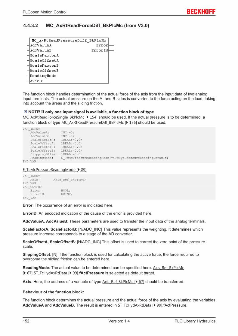
PLCopen Motion Control
PLC Library Hydraulics152 Version: 1.4
4.4.3.2 MC_AxRtReadForceDiff_BkPlcMc (from V3.0)
The function block handles determination of the actual force of the axis from the input data of two analoginput terminals. The actual pressure on the A- and B-sides is converted to the force acting on the load, takinginto account the areas and the sliding friction.
NOTE! If only one input signal is available, a function block of typeMC_AxRtReadForceSingle_BkPlcMc [} 154] should be used. If the actual pressure is to be determined, afunction block of type MC_AxRtReadPressureDiff_BkPlcMc [} 156] should be used.VAR_INPUT AdcValueA: INT:=0; AdcValueB: INT:=0; ScaleFactorA: LREAL:=0.0; ScaleOffsetA: LREAL:=0.0; ScaleFactorB: LREAL:=0.0; ScaleOffsetB: LREAL:=0.0; SlippingOffset: LREAL:=0.0; ReadingMode: E_TcMcPressureReadingMode:=iTcHydPressureReadingDefault;END_VAR
E_TcMcPressureReadingMode [} 89]VAR_INOUT Axis: Axis_Ref_BkPlcMc;END_VARVAR_OUTPUT Error: BOOL; ErrorID: UDINT;END_VAR
Error: The occurrence of an error is indicated here.
ErrorID: An encoded indication of the cause of the error is provided here.
AdcValueA, AdcValueB: These parameters are used to transfer the input data of the analog terminals.
ScaleFactorA, ScaleFactorB: [N/ADC_INC] This value represents the weighting. It determines whichpressure increase corresponds to a stage of the AD converter.
ScaleOffsetA, ScaleOffsetB: [N/ADC_INC] This offset is used to correct the zero point of the pressurescale.
SlippingOffset: [N] If the function block is used for calculating the active force, the force required toovercome the sliding friction can be entered here.
ReadingMode: The actual value to be determined can be specified here. Axis_Ref_BkPlcMc[} 67].ST_TcHydAxRtData [} 99].fActPressure is selected as default target.
Axis: Here, the address of a variable of type Axis_Ref_BkPlcMc [} 67] should be transferred.
Behaviour of the function block:
The function block determines the actual pressure and the actual force of the axis by evaluating the variablesAdcValueA and AdcValueB. The result is entered in ST_TcHydAxRtData [} 99].fActPressure.

PLCopen Motion Control
PLC Library Hydraulics 153Version: 1.4
NOTE! The parameters assigned to an axis can be saved in ST_TcHydAxParam.fCustomerData[...],for example. This ensures that the data are loaded, saved and backed up together with the standardparameters of the axis and are also exported and imported, as required.
Determining a differential actual pressure
Commissioning is usually done in one of three ways.
Commissioning option A (preferred for ±10V)
In this case, no movement of the axis is required. The achievable accuracy is sufficient for high-qualitypressure sensors in most cases.
• The rated pressure of the pressure sensors divided by AdcValueAMAX or AdcValueBMAX should beentered as ScaleFactorA and ScaleFactorB.
• If the function block is used for determining the actual pressure, the parameters ScaleArreaA andScaleArreaB should be set to 1.0. Otherwise these parameters should be specified for an actual forcein N (= Newton) in mm2.
Commissioning option B
For this option it is necessary that a function block can be approached with full system pressure in bothdirections. A genuine movement of the axis is not required. Approaching of the end stops can be modeled bylimiting the axis movement through provisional limits or even complete mechanical fixing.
• All function blocks, which respond to the value of ST_TcHydAxRtData [} 99].fActPressure, must bedeactivated.
• First, slowly approach the lower function block (in the direction of decreasing actual position). Thevalues for AdcValueA and AdcValueB are determined and logged. The system pressure should nowbe present on the A-side and the tank pressure – and therefore the ambient pressure – on the B-side.Should this not be the case for some reason, the pressures on the A- and B-side should be determinedthrough measurement.
• Then, slowly approach the upper function block (in the direction of increasing actual position). Thevalues for AdcValueA and AdcValueB are again determined and logged. Now measure the pressuresagain.
• The parameters to be entered can then be calculated as follows:ScaleFactorA := (PressureAMAX - PressureAMIN) / (AdcValueAMAX - AdcValueAMIN);ScaleFactorB := (PressureBMAX - PressureBMIN) / (AdcValueBMAX - AdcValueBMIN);ScaleOffsetA := PressureAMIN - ScaleFactorA * AdcValueA;MIN
ScaleOffsetB := PressureBMIN - ScaleFactorB * AdcValueB;MIN
Commissioning option C
Alternatively, commissioning can be carried out without axis control. However, the accuracy that can beachieved in this way is much lower.
• First, the axis should be made pressure-free. To this end, switch off the compressor and relieve thepressure in the accumulator.
• Ensure that the axis does not build up pressure. To this end, an axis that is subject to external forces(gravity etc.) should be supported mechanically. Open the valve several times in both directions, eithermanually or electrically.
• Now determine and log the values for AdcValueA and AdcValueB. The tank pressure – and thereforethe ambient pressure – should be present both on the A-side and on the B-side. Should this not be thecase for some reason, the pressures on the A- and B-side should be determined throughmeasurement. Use the values found in this way as MIN values in the equations mentioned above.
• Take the pressure for the upper limit of the electrical signal (10 V, 20 mA) from the data sheetspecifications for the pressure sensors. Use the upper limit value for the converted electrical value asAdcValueA and AdcValueB. Use these values as MAX values in the equations mentioned above.
• The parameters to be entered can then be calculated as described above.

PLCopen Motion Control
PLC Library Hydraulics154 Version: 1.4
Determining an active force
To determine an active force, first determine the actual pressure, as described above. Entering the activeareas under ScaleArreaA and ScaleArreaA causes the function block to convert the pressures on bothsides into forces, taking into account the areas.
4.4.3.3 MC_AxRtReadForceSingle_BkPlcMc (from V3.0)
The function block handles determination of the actual force of the axis from the input data of an analog inputterminal. The actual pressure on the A- or B-sides is converted to the force acting on the load, taking intoaccount the area and the sliding friction.
Note
If only one input signal is available, a function block of type MC_AxRtReadForceD-iff_BkPlcMc [} 152] should be used. If the actual pressure is to be determined, a functionblock of type MC_AxRtReadPressureDiff_BkPlcMc [} 156] should be used.
VAR_INPUT AdcValueA: INT:=0; AdcValueB: INT:=0; ScaleFactorA: LREAL:=0.0; ScaleOffsetA: LREAL:=0.0; ScaleFactorB: LREAL:=0.0; ScaleOffsetB: LREAL:=0.0; SlippingOffset: LREAL:=0.0; ReadingMode: E_TcMcPressureReadingMode:=iTcHydPressureReadingDefault;END_VARVAR_INOUT Axis: Axis_Ref_BkPlcMc;END_VARVAR_OUTPUT Error: BOOL; ErrorID: UDINT;END_VAR
Error: The occurrence of an error is indicated here.
ErrorID: An encoded indication of the cause of the error is provided here.
AdcValueA, AdcValueB: These parameters are used to transfer the input data of the analog terminals.
ScaleFactorA, ScaleFactorB: [N/ADC_INC] This value represents the weighting. It determines whichpressure increase corresponds to a stage of the AD converter.
ScaleOffsetA, ScaleOffsetB: [N/ADC_INC] This offset is used to correct the zero point of the pressurescale.
SlippingOffset: [N] If the function block is used for calculating the active force, the force required toovercome the sliding friction can be entered here.
ReadingMode: The actual value to be determined can be specified here. Axis_Ref_BkPlcMc[} 67].ST_TcHydAxRtData [} 99].fActPressure is selected as default target.
Axis: Here, the address of a variable of type Axis_Ref_BkPlcMc [} 67] should be transferred.

PLCopen Motion Control
PLC Library Hydraulics 155Version: 1.4
Behaviour of the function block:
The function block determines the actual pressure and the actual force of the axis by evaluating the variablesAdcValueA. The result is entered in ST_TcHydAxRtData [} 99].fActPressure.
The parameters assigned to an axis can be saved in ST_TcHydAxParam [} 93].fCustomerData[...], forexample. This ensures that the data are loaded, saved and backed up together with the standard parametersof the axis and are also exported and imported, as required.
Determining a differential actual pressure
If the function block is used to determine the actual pressure, the parameters ScaleArreaA andScaleArreaA should be set to 1.0 and SlippingOffset to 0.0.
Commissioning option A
In this case, no movement of the axis is required. The achievable accuracy is sufficient for high-qualitypressure sensors in most cases.
• Enter the rated pressure of the pressure sensors divided by AdcValueAMAX as ScaleFactorA.
Commissioning option B
For this option it is necessary that a function block can be approached with full system pressure in bothdirections. A genuine movement of the axis is not required. Approaching of the end stops can be modeled bylimiting the axis movement through provisional limits or even complete mechanical fixing.
• All function blocks, which respond to the value of ST_TcHydAxRtData [} 99].fActPressure, must bedeactivated.
• First, slowly approach the lower function block (in the direction of decreasing actual position). Thevalues for AdcValueA and AdcValueB are determined and logged. The system pressure should nowbe present on the A-side and the tank pressure – and therefore the ambient pressure – on the B-side.Should this not be the case for some reason, the pressures on the A- and B-side should be determinedthrough measurement.
• Then, slowly approach the upper function block (in the direction of increasing actual position). Thevalues for AdcValueA and AdcValueB are again determined and logged. Now measure the pressuresagain.
• The parameters to be entered can then be calculated as follows:ScaleFactorA := (PressureAMAX - PressureAMIN) / (AdcValueAMAX - AdcValueAMIN);ScaleFactorB := (PressureBMAX - PressureBMIN) / (AdcValueBMAX - AdcValueBMIN);ScaleOffsetA := PressureAMIN - ScaleFactorA * AdcValueA;MIN
ScaleOffsetB := PressureBMIN - ScaleFactorB * AdcValueB;MIN
Commissioning option C
Alternatively, commissioning can be carried out without axis control. However, the accuracy that can beachieved in this way is much lower.
• First, the axis should be made pressure-free. To this end, switch off the compressor and relieve thepressure in the accumulator.
• Ensure that the axis does not build up pressure. To this end, an axis that is subject to external forces(gravity etc.) should be supported mechanically. Open the valve several times in both directions, eithermanually or electrically.
• Now determine and log the values for AdcValueA and AdcValueB. The tank pressure – and thereforethe ambient pressure – should be present both on the A-side and on the B-side. Should this not be thecase for some reason, the pressures on the A- and B-side should be determined throughmeasurement. Use the values found in this way as MIN values in the equations mentioned above.
• Take the pressure for the upper limit of the electrical signal (10 V, 20 mA) from the data sheetspecifications for the pressure sensors. Use the upper limit value for the converted electrical value asAdcValueA and AdcValueB. Use these values as MAX values in the equations mentioned above.

PLCopen Motion Control
PLC Library Hydraulics156 Version: 1.4
• The parameters to be entered can then be calculated as described above.
Determining an active force
To determine an active force, first determine the actual pressure, as described above. Entering the activearea under ScaleArreaA causes the function block to convert the single-sided pressure to a force, takinginto account the area.
4.4.3.4 MC_AxRtReadPressureDiff_BkPlcMc (from V3.0)
The function block handles determination of the actual pressure of the axis from the input data of two analoginput terminals.
Note
If only one input signal is available, a function block of type MC_AxRtReadPressureSin-gle_BkPlcMc [} 158] should be used. If the force is to be determined, instead of the pres-sure, a function block of type MC_AxRtReadForceDiff_BkPlcMc [} 152] should be used.
VAR_INPUT AdcValueA: INT:=0; AdcValueB: INT:=0; ScaleFactorA: LREAL:=0.0; ScaleOffsetA: LREAL:=0.0; ScaleFactorB: LREAL:=0.0; ScaleOffsetB: LREAL:=0.0; ReadingMode: E_TcMcPressureReadingMode:=iTcHydPressureReadingDefault;END_VARVAR_INOUT Axis: Axis_Ref_BkPlcMc;END_VARVAR_OUTPUT Error: BOOL; ErrorID: UDINT;END_VAR
Error: The occurrence of an error is indicated here.
ErrorID: An encoded indication of the cause of the error is provided here.
AdcValueA, AdcValueB: These parameters are used to transfer the input data of the analog terminals.
ScaleFactorA, ScaleFactorB: [bar/ADC_INC] This value represents the weighting. It determines whichpressure increase corresponds to a stage of the AD converter.
ScaleOffsetA, ScaleOffsetB: [bar] This offset is used to correct the zero point of the pressure scale.
ReadingMode: This parameter is used to specify where the result of the evaluation is to be stored.
Axis: Here, the address of a variable of type Axis_Ref_BkPlcMc [} 67] should be transferred.
Behaviour of the function block:
The function block investigates the axis interface that has been passed to it every time it is called. During thisprocess, a problem may be detected and reported:
PLCopen Motion Control
PLC Library Hydraulics 157Version: 1.4
• If the pointer pStAxRtData in Axis_Ref_BkPlcMc [} 67] is not initialized, the function block reacts with anError and ErrorID:=dwTcHydErrCdPtrMcPlc. In this case, the axis cannot be placed into a fault state.
If these checks could be performed without problem, the actual pressure of the axis is determined byevaluating the variables AdcValueA and AdcValueB. The result is entered in ST_TcHydAxRtData[} 99].fActPressure.
The parameters assigned to an axis can be saved in ST_TcHydAxParam [} 93].fCustomerData[...], forexample. This ensures that the data are loaded, saved and backed up together with the standard parametersof the axis and are also exported and imported, as required.
Commissioning option A
In this case, no movement of the axis is required. The achievable accuracy is sufficient for high-qualitypressure sensors in most cases.
• The rated pressure of the pressure sensors divided by AdcValueAMAX or AdcValueBMAX should beentered as ScaleFactorA and ScaleFactorB.
Commissioning option B
In this case, no movement of the axis is required. The achievable accuracy is sufficient for high-qualitypressure sensors in most cases.
• The rated pressure of the pressure sensors divided by AdcValueAMAX or AdcValueBMAX should beentered as ScaleFactorA and ScaleFactorB.
Commissioning option C
For this option it is necessary that a function block can be approached with full system pressure in bothdirections. A genuine movement of the axis is not required. Approaching of the end stops can be modeled bylimiting the axis movement through provisional limits or even complete mechanical fixing.
• All function blocks, which respond to the value of ST_TcHydAxRtData [} 99].fActPressure, must bedeactivated.
• First, slowly approach the lower function block (in the direction of decreasing actual position). Thevalues for AdcValueA and AdcValueB are determined and logged. The system pressure should nowbe present on the B-side and the tank pressure – and therefore the ambient pressure – on the A-side.Should this not be the case for some reason, the pressures on the A- and B-side should be determinedthrough measurement.
• Then, slowly approach the upper function block (in the direction of increasing actual position). Thevalues for AdcValueA and AdcValueB are again determined and logged. Now measure the pressuresagain.
• The parameters to be entered can then be calculated as follows:ScaleFactorA := (PressureAMAX - PressureAMIN) / (AdcValueAMAX - AdcValueAMIN);ScaleFactorB := (PressureBMAX - PressureBMIN) / (AdcValueBMAX - AdcValueBMIN);ScaleOffsetA := PressureAMIN - ScaleFactorA * AdcValueA;MIN
ScaleOffsetB := PressureBMIN - ScaleFactorB * AdcValueB;MIN
Commissioning option D
Alternatively, commissioning can be carried out without axis control. However, the accuracy that can beachieved in this way is much lower.
• First, the axis should be made pressure-free. To this end, switch off the compressor and relieve thepressure in the accumulator.
• Ensure that the axis does not build up pressure. To this end, an axis that is subject to external forces(gravity etc.) should be supported mechanically. Open the valve several times in both directions, eithermanually or electrically.
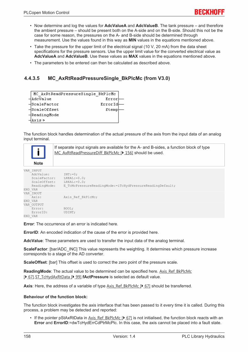
PLCopen Motion Control
PLC Library Hydraulics158 Version: 1.4
• Now determine and log the values for AdcValueA and AdcValueB. The tank pressure – and thereforethe ambient pressure – should be present both on the A-side and on the B-side. Should this not be thecase for some reason, the pressures on the A- and B-side should be determined throughmeasurement. Use the values found in this way as MIN values in the equations mentioned above.
• Take the pressure for the upper limit of the electrical signal (10 V, 20 mA) from the data sheetspecifications for the pressure sensors. Use the upper limit value for the converted electrical value asAdcValueA and AdcValueB. Use these values as MAX values in the equations mentioned above.
• The parameters to be entered can then be calculated as described above.
4.4.3.5 MC_AxRtReadPressureSingle_BkPlcMc (from V3.0)
The function block handles determination of the actual pressure of the axis from the input data of an analoginput terminal.
Note
If separate input signals are available for the A- and B-sides, a function block of typeMC_AxRtReadPressureDiff_BkPlcMc [} 156] should be used.
VAR_INPUT AdcValue: INT:=0; ScaleFactor: LREAL:=0.0; ScaleOffset: LREAL:=0.0; ReadingMode: E_TcMcPressureReadingMode:=iTcHydPressureReadingDefault;END_VARVAR_INOUT Axis: Axis_Ref_BkPlcMc;END_VARVAR_OUTPUT Error: BOOL; ErrorID: UDINT;END_VAR
Error: The occurrence of an error is indicated here.
ErrorID: An encoded indication of the cause of the error is provided here.
AdcValue: These parameters are used to transfer the input data of the analog terminal.
ScaleFactor: [bar/ADC_INC] This value represents the weighting. It determines which pressure increasecorresponds to a stage of the AD converter.
ScaleOffset: [bar] This offset is used to correct the zero point of the pressure scale.
ReadingMode: The actual value to be determined can be specified here. Axis_Ref_BkPlcMc[} 67].ST_TcHydAxRtData [} 99].fActPressure is selected as default value.
Axis: Here, the address of a variable of type Axis_Ref_BkPlcMc [} 67] should be transferred.
Behaviour of the function block:
The function block investigates the axis interface that has been passed to it every time it is called. During thisprocess, a problem may be detected and reported:
• If the pointer pStAxRtData in Axis_Ref_BkPlcMc [} 67] is not initialised, the function block reacts with anError and ErrorID:=dwTcHydErrCdPtrMcPlc. In this case, the axis cannot be placed into a fault state.

PLCopen Motion Control
PLC Library Hydraulics 159Version: 1.4
If these checks could be performed without problem, the actual pressure of the axis is determined byevaluating the variables AdcValue. The result is entered in ST_TcHydAxRtData [} 99].fActPressure.
Note
The parameters assigned to an axis can be saved in ST_TcHydAxParam [} 93].fCustomer-Data[...], for example. This ensures that the data are loaded, saved and backed up togetherwith the standard parameters of the axis and are also exported and imported, as required.
Commissioning option A
For this option it is necessary that a function block can be approached with full system pressure in bothdirections. A genuine movement of the axis is not required. Approaching of the end stops can be modeled bylimiting the axis movement through provisional limits or even complete mechanical fixing.
• All function blocks, which respond to the value of ST_TcHydAxRtData [} 99].fActPressure, must bedeactivated.
• First, slowly approach the lower function block (in the direction of decreasing actual position). Thevalue for AdcValue is determined and logged. The system pressure should now be present on the B-side and the tank pressure – and therefore the ambient pressure – on the A-side. Should this not bethe case for some reason, the pressures on the A- and B-side should be determined throughmeasurement.
• Then, slowly approach the upper function block (in the direction of increasing actual position). Thevalue for AdcValue is determined and logged again. Now measure the pressures again.
• The parameters to be entered can then be calculated as follows:ScaleFactor := (PressureMAX - PressureMIN) / (AdcValueMAX - AdcValueMIN);ScaleOffset := PressureMIN - ScaleFactor * AdcValue;MIN
Commissioning option B
Alternatively, commissioning can be carried out without axis control. However, the accuracy that can beachieved in this way is much lower.
• First, the axis should be made pressure-free. To this end, switch off the compressor and relieve thepressure in the accumulator.
• Ensure that the axis does not build up pressure. To this end, an axis that is subject to external forces(gravity etc.) should be supported mechanically. Open the valve several times in both directions, eithermanually or electrically.
• Now the value for AdcValue is determined and logged. The tank pressure – and therefore the ambientpressure – should be present both on the A-side and on the B-side. If this is not the case for somereason, the pressure on the A-side should be determined through measurement. Use the values foundin this way as MIN values in the equations mentioned above.
• Take the pressure for the upper limit of the electrical signal (10 V, 20 mA) from the data sheetspecifications for the pressure sensors. Use the upper limit value for the converted electrical value asAdcValue. Use these values as MAX values in the equations mentioned above.
• The parameters to be entered can then be calculated as described above.
4.4.4 FunctionGenerator
4.4.4.1 MC_FunctionGeneratorFD_BkPlcMc (from V3.0.31)

PLCopen Motion Control
PLC Library Hydraulics160 Version: 1.4
The function block calculates the signals of a function generator.VAR_OUTPUT Sinus: LREAL; Cosinus: LREAL; Rectangle: LREAL; SawTooth: LREAL;END_VARVAR_INOUT stTimeBase: ST_FunctionGeneratorTB_BkPlcMc; stFunctionDef: ST_FunctionGeneratorFD_BkPlcMc;END_VAR
Sinus, Cosinus, Rectangle, SawTooth: The output signals of the function generator.
stTimeBase: A structure with the parameters of the time base of this function generator.
stFunctionDef: A structure with the definitions of the output signals of a function generator.
Behaviour of the function block
The output signals are determined from stTime base.CurrentRatio and the parameters in stFunctionDef[} 92].
The time base in stTimeBase should be updated with an MC_FunctionGeneratorTB_BkPlcMc [} 161]()function block.
To change the operating frequency, an MC_FunctionGeneratorSetFrq_BkPlcMc [} 160]() function block shouldbe used.
4.4.4.2 MC_FunctionGeneratorSetFrq_BkPlcMc (from V3.0.31)
The function block updates the operating frequency of a time base for one or several function generators[} 159].VAR_INPUT Frequency: LREAL; CycleTime: LREAL;END_VARVAR_INOUT stTimeBase: ST_FunctionGeneratorTB_BkPlcMc;END_VAR
Frequency: The operating frequency to be used.
CycleTime: The cycle time of the calling task.
stTimeBase: A structure with the parameters of the time base of one or several function generators [} 92].
Behaviour of the function block
The function block sets stTimeBase.Frequency to the transferred value. stTimeBase.CurrentTime isadjusted, if required.
The function block uses stTimeBase.Freeze to prevent a collision with MC_FunctionGeneratorTB_BkPlcMc[} 161]() function blocks. Thus, it can also be called from another task.

PLCopen Motion Control
PLC Library Hydraulics 161Version: 1.4
4.4.4.3 MC_FunctionGeneratorTB_BkPlcMc (from V3.0.31)
The function block updates a time base for one or several function generators [} 159].VAR_INPUT CycleTime: LREAL;END_VARVAR_INOUT stTimeBase: ST_FunctionGeneratorTB_BkPlcMc;END_VAR
CycleTime: The cycle time of the calling task.
stTimeBase: A structure with the parameters of the time base of one or several function generators [} 92].
Behaviour of the function block
If stTimeBase.Freeze is not set, stTimeBase.CurrentTime is updated with CycleTime andstTimeBase.CurrentRatio is determined. stTimeBase.Frequency is taken into account.
To change the operating frequency, an MC_FunctionGeneratorSetFrq_BkPlcMc [} 160]() function block shouldbe used.
4.4.5 TableFunctions
4.4.5.1 MC_AxTableToBinFile_BkPlcMc (from V3.0)
The function block writes the contents of a table to a binary file.VAR_INPUT Execute: BOOL:=FALSE; pTable: POINTER TO LREAL:=0; LowIdx: INT:=0; HighIdx: INT:=0; FileName: STRING(255):='';END_VARVAR_INOUT Axis: Axis_Ref_BkPlcMc;END_VARVAR_OUTPUT Busy: BOOL; Done: BOOL; Error: BOOL; ErrorID: UDINT;END_VAR
Execute: The writing process is initiated by a rising edge at this input.
pTable: This parameter is used to transfer the address of an ARRAY[nFirstIdx..nLastIdx.1..2].

PLCopen Motion Control
PLC Library Hydraulics162 Version: 1.4
LowIdx: This parameter is used to transfer the lower index of the ARRAY, whose address is transferred aspTable.
HighIdx: This parameter is used to transfer the upper index of the ARRAY, whose address is transferred aspTable.
FileName: This parameter can be used to specify a file name.
Busy: Indicates that a command is being processed.
Done: Successful processing of the reference travel is indicated here.
Error: The occurrence of an error is indicated here.
ErrorID: An encoded indication of the cause of the error is provided here.
Axis: Here, the address of a variable of type Axis_Ref_BkPlcMc [} 67] should be transferred.
Behaviour of the function block
A rising edge at Execute causes the function block to examine the transferred parameters. A number ofproblems can be detected and reported during this process:
• If LowIdx is negative, the system responds with Error and ErrorID=dwTcHydErrCdTblEntryCount.• If pTable=0, the system responds with Error and ErrorID=dwTcHydErrCdTblEntryCount.• If LowIdx and HighIdx describe a table with fewer than five rows, the system responds with Error and
ErrorID=dwTcHydErrCdTblEntryCount.
If these checks were performed without problems, the write operation is started. Busy is TRUE for theduration of the operation. This can lead to some further problems, which are indicated by various errorcodes. Successful writing of the file is indicated with Done.
A falling edge at Execute clears all the pending output signals. If Execute is set to FALSE while theoperation is still active, the initiated operation continues unaffected. The signals at the end of the operation(Error, ErrorID, Done) apply for one cycle.
If a FileName is specified, it must be complete (including the drive letter and the path, if applicable, alwaysincluding the file type), since it is used by function block without any further modification or amendment.
If no FileName is specified, the function block uses the path and the file name, which were specified throughthe MC_AxUtiStandardInit_BkPlcMc [} 182] function block. File type TBL is used here, to distinguish from theparameter file with file type DAT.
NOTE! The file contents cannot be read or modified with an ASCII editor.
4.4.5.2 MC_AxTableToAsciFile_BkPlcMc (from V3.0)
The function block writes the contents of a table to a text file.VAR_INPUT Execute: BOOL:=FALSE; pTable: POINTER TO LREAL:=0; LowIdx: INT:=0; HighIdx: INT:=0; FileName: STRING(255):='';END_VAR

PLCopen Motion Control
PLC Library Hydraulics 163Version: 1.4
VAR_INOUT Axis: Axis_Ref_BkPlcMc;END_VARVAR_OUTPUT Busy: BOOL; Done: BOOL; Error: BOOL; ErrorID: UDINT;END_VAR
Execute: The writing process is initiated by a rising edge at this input.
pTable: This parameter is used to transfer the address of an ARRAY[nFirstIdx..nLastIdx.1..2].
LowIdx: This parameter is used to transfer the lower index of the ARRAY, whose address is transferred aspTable.
HighIdx: This parameter is used to transfer the upper index of the ARRAY, whose address is transferred aspTable.
FileName: This parameter can be used to specify a file name.
Busy: Indicates that a command is being processed.
Done: Successful processing of the reference travel is indicated here.
Error: The occurrence of an error is indicated here.
ErrorID: An encoded indication of the cause of the error is provided here.
Axis: Here, the address of a variable of type Axis_Ref_BkPlcMc [} 67] should be transferred.
Behaviour of the function block
A rising edge at Execute causes the function block to examine the transferred parameters. A number ofproblems can be detected and reported during this process:
• If LowIdx is negative, the system responds with Error and ErrorID=dwTcHydErrCdTblEntryCount.• If pTable=0, the system responds with Error and ErrorID=dwTcHydErrCdTblEntryCount.• If LowIdx and HighIdx describe a table with fewer than five rows, the system responds with Error and
ErrorID=dwTcHydErrCdTblEntryCount.
If these checks were performed without problems, the write operation is started. Busy is TRUE for theduration of the operation. This can lead to some further problems, which are indicated by various errorcodes. Successful writing of the file is indicated with Done.
A falling edge at Execute clears all the pending output signals. If Execute is set to FALSE while theoperation is still active, the initiated operation continues unaffected. The signals at the end of the operation(Error, ErrorID, Done) apply for one cycle.
If a FileName is specified, it must be complete (including the drive letter and the path, if applicable, alwaysincluding the file type), since it is used by function block without any further modification or amendment.
If no FileName is specified, the function block uses the path and the file name, which were specified throughthe MC_AxUtiStandardInit_BkPlcMc [} 182] function block. File type TXT is used here, to distinguish from theparameter file with file type DAT.
NOTE! The file contents can be read or modified with an ASCII editor. Changes of the content canmake correct reading or the intended use impossible or change the effect of the table in a way that isdifficult to trace. Manual changes should therefore be implemented very carefully, if at all, and onlyby competent persons.
PLCopen Motion Control
PLC Library Hydraulics164 Version: 1.4
4.4.5.3 MC_AxTableReadOutNonCyclic_BkPlcMc (from V3.0)
The function block determines the slave values assigned to a master value with the aid of a table.
NOTE! This function block is a component of cam plates or similar non-linear couplings. It isgenerally not called direct by an application.VAR_INPUT pTable: POINTER TO LREAL:=0; fMasterValue: LREAL:=0.0; nFirstIdx: UDINT:=1; nLastIdx: UDINT:=1; bReInit: BOOL:=FALSE;END_VARVAR_OUTPUT fSlaveValue: LREAL:=0.0; fSlaveGear: LREAL:=0.0; bUnderRange: BOOL; bOverRange: BOOL;END_VAR
pTable: This parameter is used to transfer the address of an ARRAY[nFirstIdx..nLastIdx.1..2].
Attention
Crash of the PLC application An incorrect specification at this point causes the PLC application to crash through trig-gering of serious runtime errors (Page Fault Exception).
fMasterValue: This parameter is used to transfer the master value, for which the corresponding slave valuesare to be determined.
nFirstIdx: This parameter is used to transfer the lower index of the ARRAY, whose address is transferred aspTable.
Attention: An incorrect specification at this point causes the PLC application to crash through triggering ofserious runtime errors (Page Fault Exception).
nLastIdx: This parameter is used to transfer the upper index of the ARRAY, whose address is transferred aspTable.
Attention
Crash of the PLC application An incorrect specification at this point causes the PLC application to crash through trig-gering of serious runtime errors (Page Fault Exception).
bReInit: This input indicates to the function block that the search procedure should start at the top of thetable.
fSlaveValue: This parameter is used to output the slave value belonging to fMasterValue.
fSlaveGear: This parameter is used to output the local slope of the slave values at the point in the tablespecified by the master.
bUnderRange: This output becomes TRUE, if the master value reaches the bottom of the table or fallsbelow it.
bOverRange: This output becomes TRUE, if the master value reaches the top of the table or exceeds it.

PLCopen Motion Control
PLC Library Hydraulics 165Version: 1.4
Behaviour of the function block
The function block searches inside the transferred table for a master pair of values, which matches orincludes the transferred fMasterValue. Within the found intervals a linear intermediate interpolation iscalculated. The result is output as fSlaveValue. The local slope determined in this calculation is output asfSlaveGear.
If fMasterValue is below the value range described by the table, bUnderRange is indicated. The valueoutput as fSlaveValue is the value allocated to the lowest point of the table. 0.0 is returned as fSlaveGear.
If fMasterValue is above the value range described by the table, bOverRange is indicated. The value outputas fSlaveValue is the value allocated to the highest point of the table. 0.0 is returned as fSlaveGear.
The return value fSlaveGear represents the ratio of the first derivatives of fMasterValue and fSlaveValue. IffMasterValue represents a position or a virtual time, the multiplication of master progress velocity andfSlaveGear returns the set slave velocity. This can be used to generate a pilot-control velocity. AnMC_AxRtSetExtGenValues_BkPlcMc [} 180] function block is preferable for this purpose.
4.4.5.4 MC_AxTableFromBinFile_BkPlcMc (from V3.0)
The function block reads the contents of a table from a binary file.VAR_INPUT Execute: BOOL:=FALSE; pTable: POINTER TO LREAL:=0; LowIdx: INT:=0; HighIdx: INT:=0; FileName: STRING(255):='';END_VARVAR_INOUT Axis: Axis_Ref_BkPlcMc;END_VARVAR_OUTPUT Busy: BOOL; Done: BOOL; Error: BOOL; ErrorID: UDINT; LastIdx: INT:=0;END_VAR
Execute: A rising edge at this input starts the read process.
pTable: This parameter is used to transfer the address of an ARRAY[nFirstIdx..nLastIdx.1..2].
LowIdx: This parameter is used to transfer the lower index of the ARRAY, whose address is transferred aspTable.
HighIdx: This parameter is used to transfer the upper index of the ARRAY, whose address is transferred aspTable.
FileName: This parameter can be used to specify a file name.
Busy: Indicates that a command is being processed.
Done: Successful processing of the reference travel is indicated here.
Error: The occurrence of an error is indicated here.
ErrorID: An encoded indication of the cause of the error is provided here.

PLCopen Motion Control
PLC Library Hydraulics166 Version: 1.4
LastIdx: This parameter is used to indicate the index of the last table row defined by the read operation.
Axis: Here, the address of a variable of type Axis_Ref_BkPlcMc [} 67] should be transferred.
Behaviour of the function block
A rising edge at Execute causes the function block to examine the transferred parameters. A number ofproblems can be detected and reported during this process:
• If LowIdx is negative, the system responds with Error and ErrorID=dwTcHydErrCdTblEntryCount.• If pTable=0, the system responds with Error and ErrorID=dwTcHydErrCdTblEntryCount.• f LowIdx and HighIdx describe a table with fewer than five rows, the system responds with Error and
ErrorID=dwTcHydErrCdTblEntryCount.
If these checks were performed without problems, the read operation is started. Busy is TRUE for theduration of the operation. This can lead to some further problems, which are indicated by various errorcodes. Successful reading of the file is indicated with Done.
A falling edge at Execute clears all the pending output signals. If Execute is set to FALSE while theoperation is still active, the initiated operation continues unaffected. The signals at the end of the operation(Error, ErrorID, Done) apply for one cycle.
If a FileName is specified, it must be complete (including the drive letter and the path, if applicable, alwaysincluding the file type), since it is used by function block without any further modification or amendment.
If no FileName is specified, the function block uses the path and the file name, which were specified throughthe MC_AxUtiStandardInit_BkPlcMc [} 182] function block. File type TBL is used here, to distinguish from theparameter file with file type DAT.
NOTE! The file contents cannot be read or modified with an ASCII editor.
4.4.5.5 MC_AxTableFromAsciFile_BkPlcMc (from V3.0)
The function block reads the contents of a table from a text file.VAR_INPUT Execute: BOOL:=FALSE; pTable: POINTER TO LREAL:=0; LowIdx: INT:=0; HighIdx: INT:=0; FileName: STRING(255):='';END_VARVAR_INOUT Axis: Axis_Ref_BkPlcMc;END_VARVAR_OUTPUT Busy: BOOL; Done: BOOL; Error: BOOL; ErrorID: UDINT; LastIdx: INT:=0;END_VAR
Execute: A rising edge at this input starts the read process.
pTable: This parameter is used to transfer the address of an ARRAY[nFirstIdx..nLastIdx.1..2].

PLCopen Motion Control
PLC Library Hydraulics 167Version: 1.4
LowIdx: This parameter is used to transfer the lower index of the ARRAY, whose address is transferred aspTable.
HighIdx: This parameter is used to transfer the upper index of the ARRAY, whose address is transferred aspTable.
FileName: This parameter can be used to specify a file name.
Busy: Indicates that a command is being processed.
Done: Successful processing of the reference travel is indicated here.
Error: The occurrence of an error is indicated here.
ErrorID: An encoded indication of the cause of the error is provided here.
LastIdx: This parameter is used to indicate the index of the last table row defined by the read operation.
Axis: Here, the address of a variable of type Axis_Ref_BkPlcMc [} 67] should be transferred.
Behaviour of the function block
A rising edge at Execute causes the function block to examine the transferred parameters. A number ofproblems can be detected and reported during this process:
• If LowIdx is negative, the system responds with Error and ErrorID=dwTcHydErrCdTblEntryCount.• If pTable=0, the system responds with Error and ErrorID=dwTcHydErrCdTblEntryCount.• If LowIdx and HighIdx describe a table with fewer than five rows, the system responds with Error and
ErrorID=dwTcHydErrCdTblEntryCount.
If these checks were performed without problems, the read operation is started. Busy is TRUE for theduration of the operation. This can lead to some further problems, which are indicated by various errorcodes. Successful reading of the file is indicated with Done.
A falling edge at Execute clears all the pending output signals. If Execute is set to FALSE while theoperation is still active, the initiated operation continues unaffected. The signals at the end of the operation(Error, ErrorID, Done) apply for one cycle.
If a FileName is specified, it must be complete (including the drive letter and the path, if applicable, alwaysincluding the file type), since it is used by function block without any further modification or amendment.
If no FileName is specified, the function block uses the path and the file name, which were specified throughthe MC_AxUtiStandardInit_BkPlcMc [} 182] function block. File type TXT is used here, to distinguish from theparameter file with file type DAT.
NOTE! The file contents can be read or modified with an ASCII editor. Changes of the content canmake correct reading or the intended use impossible or change the effect of the table in a way that isdifficult to trace. Manual changes should therefore be implemented very carefully, if at all, and onlyby competent persons.
4.4.6 Generators
4.4.6.1 MC_AxRuntime_BkPlcMc (from V3.0)
This function block performs the task of a set value generator. To this end a profile-specific function block iscalled, depending on the value set as nProfileType in Axis.ST_TcHydAxParam [} 93].

PLCopen Motion Control
PLC Library Hydraulics168 Version: 1.4
VAR_OUTPUT Error: BOOL; ErrorID: UDINT;END_VARVAR_INOUT Axis: Axis_Ref_BkPlcMc;END_VAR
Error: The occurrence of an error is indicated here.
ErrorID: An encoded indication of the cause of the error is provided here.
Axis: Here, the address of a variable of type Axis_Ref_BkPlcMc [} 67] should be transferred.
Behavior of the function block
The function block investigates the axis interface that has been passed to it every time it is called. A numberof problems can be detected and reported during this process:
• If one of the pointers has not been initialised the function block reacts with Error and withErrorID:=dwTcHydErrCdPtrPlcMc or dwTcHydErrCdPtrMcPlc.
If it is possible to carry out these checks without encountering any problems, the set value generation isexecuted by calling an appropriate function block corresponding to the nProfileType inAxis.ST_TcHydAxParam [} 93].
The following generators are presently available:

PLCopen Motion Control
PLC Library Hydraulics 169Version: 1.4
nProfileType DescriptioniTcMc_ProfileCtrlBased [} 170] Standard profile: Single-stage time-referenced acceleration, displacement-
referenced (square root) braking ramp, target approach at creep velocity,selectable behavior when stationary.An axis in motion can be restarted at any time (new target, new velocity etc.),except in error state or in a state with dependent control value generation.Note: Overshooting the new target can happen even if the axis is in front ofthe target position at the time of the start.Note: The function block can be parameterized such that it startsautomatically and assumes an active motion state under certain conditions,which are defined through its parameters.Note: This generator type can optionally operate in purely time-controlledmode with continuously closed position controller.
iTcMc_ProfileJerkBased Standard profile: Single- or two-stage time-controlled acceleration throughoptional jerk limitation, displacement-controlled (square root generator)braking ramp, target approach with jerk limitation, selectable behavior in idlestate.An axis in motion can be restarted at any time (new target, new velocity etc.),except in error state or in a state with dependent control value generation.Note: Overshooting the new target can happen even if the axis is in front ofthe target position at the time of the start.Note: The function block can be parameterized such that it startsautomatically and assumes an active motion state under certain conditions,which are defined through its parameters.Note: This generator type can optionally operate in purely time-controlledmode with continuously closed position controller.Note: Some functions are not supported by this generator type, or not fully.
iTcMc_ProfileTimePosCtrl Note: Only present for compatibility reasons; will shortly no longer besupported.Special profile: Two stage acceleration (initially time-referenced, thendisplacement-referenced following square root curve), displacement-referenced (square root) braking ramp, target approach at creep velocity,selectable behavior when stationary.It is not possible to execute a start for an axis that is already travelling (newtarget, new velocity etc.).
iTcMc_ProfileCosine Note: Only present for compatibility reasons; will shortly no longer besupported.Special profile: Two stage acceleration (initially time-referenced, thendisplacement-referenced following cosine curve), displacement-referenced(cosine) braking ramp, target approach at creep velocity, selectable behaviorwhen stationary.It is not possible to execute a start for an axis that is already travelling (newtarget, new velocity etc.).
iTcMc_ProfileTimeRamp[} 172]
Special profile: Single-stage time-controlled acceleration, time-controlledbraking ramp, target approach with creep speed, conditionally selectablebehavior in idle state. The generator uses position cams instead of anencoder.An axis in motion can be restarted (new target, new velocity etc.), except inerror state.Note: This generator type is intended for axes, which only have digital camsinstead of an encoder.
If only the usual blocks (encoder, generator, finish, drive) for the axis are to be called, a block of typeMC_AxStandardBody_BkPlcMc [} 181] should be used for simplicity.
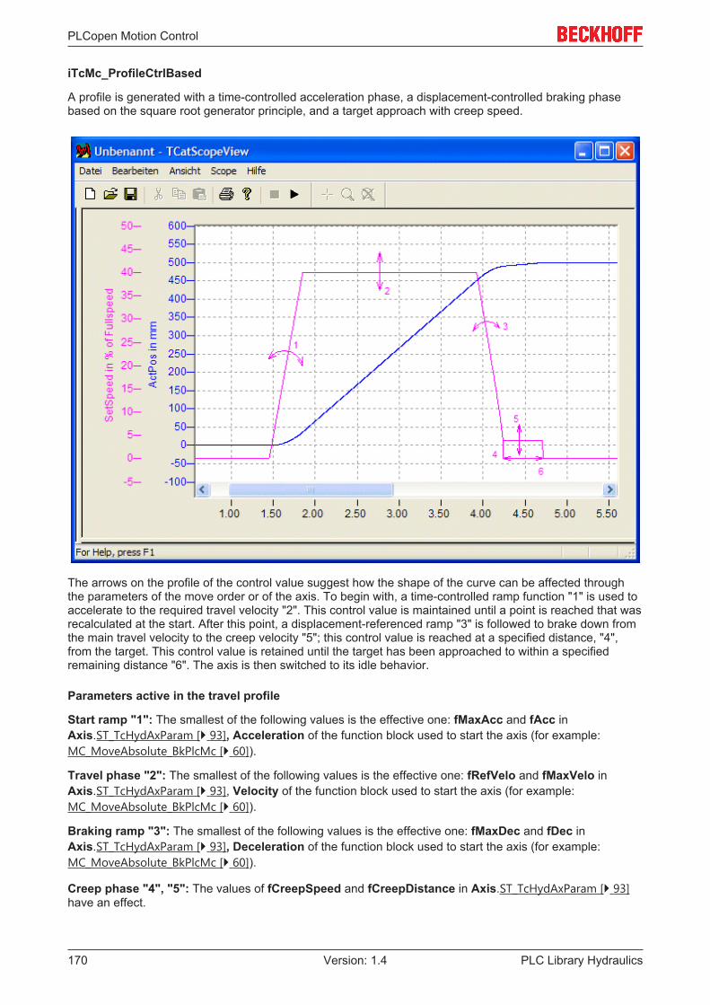
PLCopen Motion Control
PLC Library Hydraulics170 Version: 1.4
iTcMc_ProfileCtrlBased
A profile is generated with a time-controlled acceleration phase, a displacement-controlled braking phasebased on the square root generator principle, and a target approach with creep speed.
The arrows on the profile of the control value suggest how the shape of the curve can be affected throughthe parameters of the move order or of the axis. To begin with, a time-controlled ramp function "1" is used toaccelerate to the required travel velocity "2". This control value is maintained until a point is reached that wasrecalculated at the start. After this point, a displacement-referenced ramp "3" is followed to brake down fromthe main travel velocity to the creep velocity "5"; this control value is reached at a specified distance, "4",from the target. This control value is retained until the target has been approached to within a specifiedremaining distance "6". The axis is then switched to its idle behavior.
Parameters active in the travel profile
Start ramp "1": The smallest of the following values is the effective one: fMaxAcc and fAcc inAxis.ST_TcHydAxParam [} 93], Acceleration of the function block used to start the axis (for example:MC_MoveAbsolute_BkPlcMc [} 60]).
Travel phase "2": The smallest of the following values is the effective one: fRefVelo and fMaxVelo inAxis.ST_TcHydAxParam [} 93], Velocity of the function block used to start the axis (for example:MC_MoveAbsolute_BkPlcMc [} 60]).
Braking ramp "3": The smallest of the following values is the effective one: fMaxDec and fDec inAxis.ST_TcHydAxParam [} 93], Deceleration of the function block used to start the axis (for example:MC_MoveAbsolute_BkPlcMc [} 60]).
Creep phase "4", "5": The values of fCreepSpeed and fCreepDistance in Axis.ST_TcHydAxParam [} 93]have an effect.
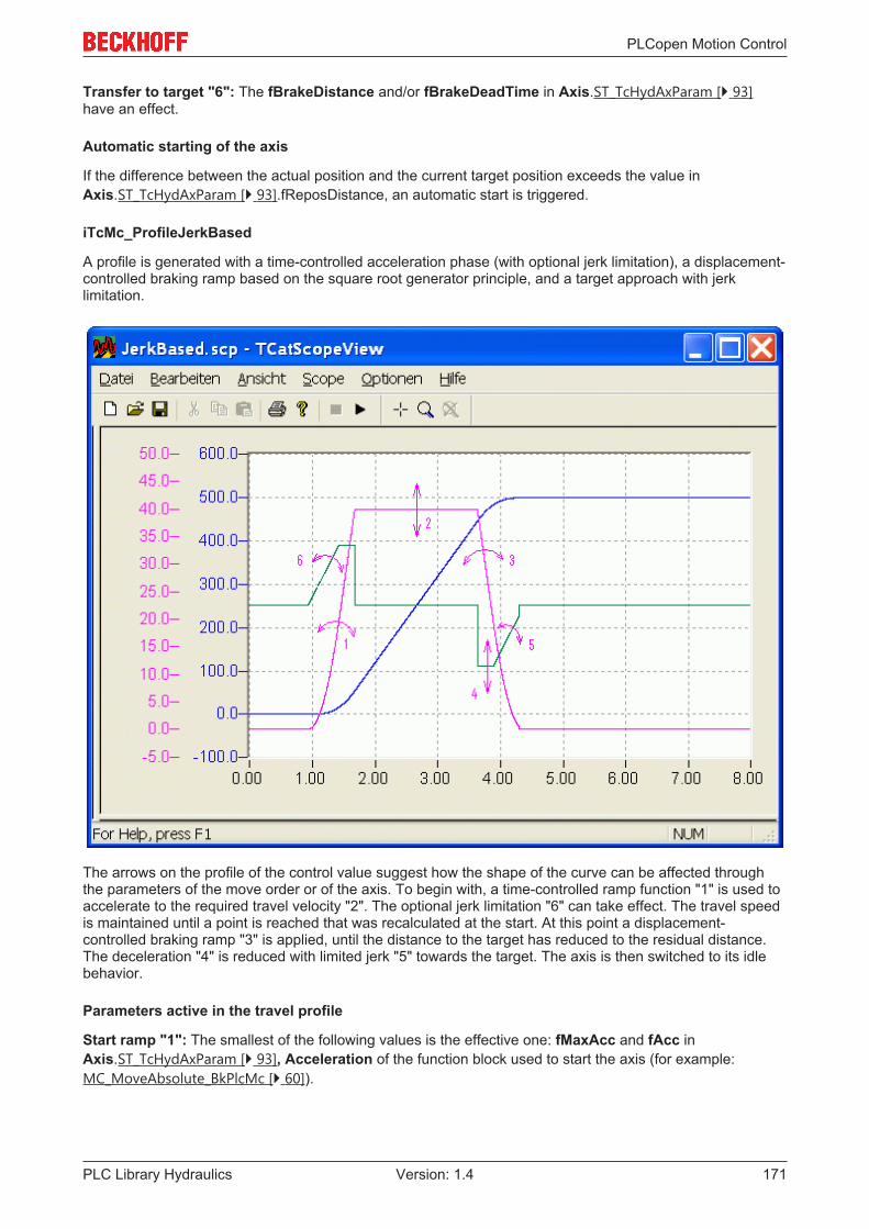
PLCopen Motion Control
PLC Library Hydraulics 171Version: 1.4
Transfer to target "6": The fBrakeDistance and/or fBrakeDeadTime in Axis.ST_TcHydAxParam [} 93]have an effect.
Automatic starting of the axis
If the difference between the actual position and the current target position exceeds the value inAxis.ST_TcHydAxParam [} 93].fReposDistance, an automatic start is triggered.
iTcMc_ProfileJerkBased
A profile is generated with a time-controlled acceleration phase (with optional jerk limitation), a displacement-controlled braking ramp based on the square root generator principle, and a target approach with jerklimitation.
The arrows on the profile of the control value suggest how the shape of the curve can be affected throughthe parameters of the move order or of the axis. To begin with, a time-controlled ramp function "1" is used toaccelerate to the required travel velocity "2". The optional jerk limitation "6" can take effect. The travel speedis maintained until a point is reached that was recalculated at the start. At this point a displacement-controlled braking ramp "3" is applied, until the distance to the target has reduced to the residual distance.The deceleration "4" is reduced with limited jerk "5" towards the target. The axis is then switched to its idlebehavior.
Parameters active in the travel profile
Start ramp "1": The smallest of the following values is the effective one: fMaxAcc and fAcc inAxis.ST_TcHydAxParam [} 93], Acceleration of the function block used to start the axis (for example:MC_MoveAbsolute_BkPlcMc [} 60]).

PLCopen Motion Control
PLC Library Hydraulics172 Version: 1.4
Travel phase "2": The smallest of the following values is the effective one: fRefVelo and fMaxVelo inAxis.ST_TcHydAxParam [} 93], Velocity of the function block used to start the axis (for example:MC_MoveAbsolute_BkPlcMc [} 60]).
Braking ramp "3", "4": The smallest of the following values is the effective one: fMaxDec and fDec inAxis.ST_TcHydAxParam [} 93], Deceleration of the function block used to start the axis (for example:MC_MoveAbsolute_BkPlcMc [} 60]).
Transfer to target "5": fMaxJerk in Axis.ST_TcHydAxParam [} 93] and fJerk of the function block used onaxis start take effect (example: MC_MoveAbsolute_BkPlcMc [} 60]) and fBrakeDistance and/orfBrakeDeadTime in Axis.ST_TcHydAxParam [} 93].
iTcMc_ProfileTimePosCtrl
NOTE! Only present for compatibility reasons; will shortly no longer be supported. It should not beused for new projects and should be replaced when existing projects are revised, if possible.
iTcMc_ProfileCosine
NOTE! Only present for compatibility reasons; will shortly no longer be supported. It should not beused for new projects and should be replaced when existing projects are revised, if possible.
iTcMc_ProfileTimeRamp
A profile is generated with a time-controlled acceleration phase, a time-controlled braking phase and a targetapproach with creep speed.
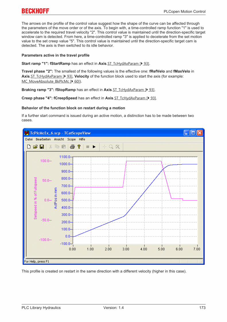
PLCopen Motion Control
PLC Library Hydraulics 173Version: 1.4
The arrows on the profile of the control value suggest how the shape of the curve can be affected throughthe parameters of the move order or of the axis. To begin with, a time-controlled ramp function "1" is used toaccelerate to the required travel velocity "2". This control value is maintained until the direction-specific targetwindow cam is detected. From here, a time-controlled ramp "3" is applied to decelerate from the set motionvalue to the set creep value "5". This control value is maintained until the direction-specific target cam isdetected. The axis is then switched to its idle behavior.
Parameters active in the travel profile
Start ramp "1": fStartRamp has an effect in Axis.ST_TcHydAxParam [} 93].
Travel phase "2": The smallest of the following values is the effective one: fRefVelo and fMaxVelo inAxis.ST_TcHydAxParam [} 93], Velocity of the function block used to start the axis (for example:MC_MoveAbsolute_BkPlcMc [} 60]).
Braking ramp "3": fStopRamp has an effect in Axis.ST_TcHydAxParam [} 93].
Creep phase "4": fCreepSpeed has an effect in Axis.ST_TcHydAxParam [} 93].
Behavior of the function block on restart during a motion
If a further start command is issued during an active motion, a distinction has to be made between twocases.
This profile is created on restart in the same direction with a different velocity (higher in this case).

PLCopen Motion Control
PLC Library Hydraulics174 Version: 1.4
This profile is created on restart in the opposite direction, in this case with the same velocity.
This profile type can only be used in a meaningful manner in combination with the encoder typeiTcMc_EncoderDigCam [} 144]. See also Special case: digital position cams.
4.4.7 Runtime
4.4.7.1 MC_AxRtCheckSyncDistance_BkPlcMc (from V3.0)
The function block checks for an invalid path (distance) after leaving the cam during homing.VAR_INPUT MaxDistance: LREAL; MinDistance: LREAL; MaxIndexWidth: LREAL;END_VARVAR_INOUT Axis: Axis_Ref_BkPlcMc;END_VARVAR_OUTPUT Active: BOOL; Exceeded: BOOL;END_VAR

PLCopen Motion Control
PLC Library Hydraulics 175Version: 1.4
MaxDistance: [mm] This parameter is used to specify the maximum permitted distance that may be traveledbetween the referencing cam and reaching of the zero pulse.
MinDistance: [mm] This parameter is used to specify the minimum distance that must be traveled betweenthe referencing cam and reaching of the zero pulse.
MaxIndexWidth: [mm] This parameter is used to specify the minimum distance that must be traveled toleave the referencing cam. (from V3.0.20)
Axis: Here, the address of a variable of type Axis_Ref_BkPlcMc [} 67] should be transferred.
Exceeded: Indicates that the axis has travelled more than MaxDistance after leaving the cam, withoutdetection of the zero pulse of the encoder.
Active: Indicates that the axis has left the cam has and expects the zero pulse of the encoder.
Behavior of the function block
The function block detects the part of the homing, in which the axis searches for the zero pulse of encoder,thereby monitoring the distance travelled. Two problems can be detected during this process:
• The axis travels MaxIndexWidth, without that the falling edges of the referencing cam being detected.• The axis travels MaxDistance, without a zero pulse being detected.• The zero pulse is detected, before the axis has traveled MinDistance.
Any problems that are detected are indicated with Exceeded. If this is to lead to an axis error, the applicationmust specify a corresponding change of state. An MC_AxRtGoErrorState_BkPlcMc [} 178] function block anda coded Error Code [} 236] should be used here.
NOTE! Monitoring for MinDistance and MaxDistance can be suppressed by setting the respectiveparameter to 0.0.
4.4.7.2 MC_AxRtFinish_BkPlcMc (from V3.0)
This function block adapts the control value that has been generated to the special features of the particularaxis. An MC_AxRtFinishLinear_BkPlcMc [} 176] function block should be used if a characteristic curvelinearisation is required.VAR_OUTPUT Error: BOOL; ErrorID: UDINT;END_VARVAR_INOUT Axis: Axis_Ref_BkPlcMc;END_VAR
Error: The occurrence of an error is indicated here.
ErrorID: An encoded indication of the cause of the error is provided here.
Axis: Here, the address of a variable of type Axis_Ref_BkPlcMc [} 67] should be transferred.
Behaviour of the function block
The function block investigates the axis interface that has been passed to it every time it is called. A numberof problems can be detected and reported during this process:
• If one of the pointers has not been initialised the function block reacts with Error and withErrorID:=dwTcHydErrCdPtrPlcMc or dwTcHydErrCdPtrMcPlc.

PLCopen Motion Control
PLC Library Hydraulics176 Version: 1.4
If these checks could be performed without problem, the control value for the axis is adapted according tothe values in Axis.ST_TcHydAxParam [} 93].
• The control value for the advance and the positional control reaction are combined to form the outputcontrol value.
• Area compensation is taken into account.• Compensation is applied for a bend in the characteristic curve.• The overlap compensation, the terminal control value and the offset compensation are included in the
calculation.
If only the usual blocks (encoder, generator, finish, drive) for the axis are to be called, a block of typeMC_AxStandardBody_BkPlcMc [} 181] should be used for simplicity.
4.4.7.3 MC_AxRtFinishLinear_BkPlcMc (from V3.0.16)
The function block deals with the adjustment of the generated control value to the special features of theaxis, taking into account a characteristic curve.VAR_INPUT EnableLinearisation: BOOL; ValveTable: POINTER TO LREAL:=0; ValveTableLowIdx: INT:=0; ValveTableHighIdx: INT:=0;END_VARVAR_OUTPUT Error: BOOL; ErrorID: UDINT;END_VARVAR_INOUT Axis: Axis_Ref_BkPlcMc;END_VAR
EnableLinearisation: TRUE at this input activates the linearisation.
ValveTable: The address of the linearisation table should be transferred here. If possible, this should be theValveCharacteristicTable of an ST_TcMcAutoIdent [} 93] linked to the axis.
ValveTableLowIdx: The index of the first point in the linearisation table.
ValveTableHighIdx: The index of the last point in the linearisation table. If possible, this should be theValveCharacteristicTblCount of an ST_TcMcAutoIdent [} 93] linked to the axis.
Error: The occurrence of an error is indicated here.
ErrorID: An encoded indication of the cause of the error is provided here.
Axis: Here, the address of a variable of type Axis_Ref_BkPlcMc [} 67] should be transferred.
Behaviour of the function block
The function block investigates the axis interface that has been passed to it every time it is called. A numberof problems may be detected:
• EnableLinearisation is FALSE.• The pointer ValveTable is not initialised.• ValveTableLowIdx is less than 0.
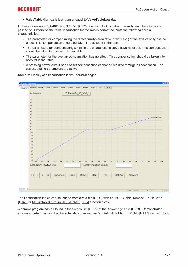
PLCopen Motion Control
PLC Library Hydraulics 177Version: 1.4
• ValveTableHighIdx is less than or equal to ValveTableLowIdx.
In these cases an MC_AxRtFinish_BkPlcMc [} 175] function block is called internally, and its outputs arepassed on. Otherwise the table linearisation for the axis is performed. Note the following specialcharacteristics:
• The parameter for compensating the directionality (area ratio, gravity etc.) of the axis velocity has noeffect. This compensation should be taken into account in the table.
• The parameters for compensating a kink in the characteristic curve have no effect. This compensationshould be taken into account in the table.
• The parameter for the overlap compensation has no effect. This compensation should be taken intoaccount in the table.
• A pressing power output or an offset compensation cannot be realized through a linearization. Thecorresponding parameters are active.
Sample: Display of a linearisation in the PlcMcManager:
The linearisation tables can be loaded from a text file [} 233] with an MC_AxTableFromAsciFile_BkPlcMc[} 166] or MC_AxTableFromBinFile_BkPlcMc [} 165] function block.
A sample program can be found in the SampleList [} 255] of the Knowledge Base [} 218]. Demonstratesautomatic determination of a characteristic curve with an MC_AxUtiAutoIdent_BkPlcMc [} 192] function block.

PLCopen Motion Control
PLC Library Hydraulics178 Version: 1.4
4.4.7.4 MC_AxRtGoErrorState_BkPlcMc (from V3.0)
(not recommended) This function block places the axis into a fault state.VAR_INPUT Trigger: BOOL; ErrorID: UDINT; NoLogging: BOOL;END_VARVAR_INOUT Axis: Axis_Ref_BkPlcMc;END_VAR
Trigger: A rising edge at this input places the axis in a fault state.
ErrorCode: An encoded indication of the cause of the error is provided here.
NoLogging: TRUE at this input suppresses the output of a message.
Axis: Here, the address of a variable of type Axis_Ref_BkPlcMc [} 67] should be transferred.
Behaviour of the function block
The axis is placed into a fault state by a rising edge at the Trigger input.
Requirements:
• The value at the ErrorCode input is not equal to 0.• The axis is not already in a fault state.
NOTE! If NoLogging is FALSE (default state), message containing information on the affected axisand the ErrorCode is generated during the transition of the axis to the error state. This defaultmessage should be replaced with a message that is meaningful for the application. In this case thedefault message should be suppressed by setting NoLogging to TRUE.
4.4.7.5 MC_AxRtMoveChecking_BkPlcMc (from V3.0)
The function block monitors the response of an axis.VAR_INPUT Enable: BOOL; MinDistance: LREAL; Filter: LREAL;END_VARVAR_OUPUT Triggered: BOOL; Timeout: BOOL;END_VAR

PLCopen Motion Control
PLC Library Hydraulics 179Version: 1.4
VAR_INOUT Axis: Axis_Ref_BkPlcMc;END_VAR
Enable: TRUE at this input activates the monitoring.
MinDistance: [mm] The required minimum distance must be transferred here.
Filter: [s] The measuring time must be specified here.
Triggered: This output indicates that the axis was set to error state.
Timeout: This output indicates that monitoring was triggered.
Axis: Here, the address of a variable of type Axis_Ref_BkPlcMc [} 67] should be transferred.
Behavior of the function block
The function block continuously checks whether the axis has travelled at least a MinDistance within Filter inthe direction that matches the required motion. If this is not the case, timeout is indicated. If Enable isTRUE, the axis is set to error state dwTcHydErrCdNotMoving = 16#435D = 17245. This is indicatedthrough Triggered.
4.4.7.6 MC_AxRtSetDirectOutput_BkPlcMc (from V3.0)
The function block issues a control value, regardless of a profile generation.VAR_INPUT Enable: BOOL; OutValue: LREAL; RampTime: LREAL;END_VARVAR_OUPUT Busy: BOOL; CommandAborted: BOOL; Error: BOOL; ErrorID: UDINT;END_VARVAR_INOUT Axis: Axis_Ref_BkPlcMc;END_VAR
Enable: TRUE at this input activates the output.
OutValue: The control value to be output should be transferred here.
RampTime: [s] Here, the time should be specified in which the control value would reach full scale.
Busy: Indicates that a command is being processed.
CommandAborted: This indicates abortion of the function.
Error: The occurrence of an error is indicated here.
ErrorID: An encoded indication of the cause of the error is provided here.
Axis: Here, the address of a variable of type Axis_Ref_BkPlcMc [} 67] should be transferred.

PLCopen Motion Control
PLC Library Hydraulics180 Version: 1.4
Behavior of the function block
A positive edge at Enable activates the function. The axis is put into states McState_Continousmotion [} 78]and iTcHydStateExtGenerated [} 71], and Busy becomes TRUE. The control value of the axis is updated withOutValue. The rate of change is specified through RampTime.
If Enable is set to FALSE, the control value is brought to 0.0 using RampTime, and the function isterminated. Only then does Busy become FALSE.
If another function block takes over control of the axis while the MC_AxRtSetDirectOutput_BkPlcMc isactive, the function block terminates its function and indicates CommandAborted.
4.4.7.7 MC_AxRtSetExtGenValues_BkPlcMc (from V3.0)
The function block supplies an axis with command variables, which do not originate from the axis' owngenerator.VAR_INPUT Enable: BOOL; Position: LREAL:=0.0; Velocity: LREAL:=0.0; TargetPosition: LREAL:=0.0;END_VARVAR_OUTPUT Error: BOOL; ErrorID: UDINT;END_VARVAR_INOUT Axis: Axis_Ref_BkPlcMc;END_VAR
Enable: TRUE at this input activates the transfer of the command variables provided.
Position: [mm] Set position value to be transferred cyclically.
Velocity: [mm/s] Set velocity value to be transferred cyclically.
TargetPosition: [mm] Target position value for the current motion to be transferred cyclically.
Error: The occurrence of an error is indicated here.
ErrorID: An encoded indication of the cause of the error is provided here.
Axis: Here, the address of a variable of type Axis_Ref_BkPlcMc [} 67] should be transferred.
Behavior of the function block
The function block investigates the axis interface that has been passed to it every time it is called. If apositive edge is detected at Execute, the axis is put in state McState_Synchronizedmotion andiTcHydStateExtGenerated.
If Execute is TRUE, the values of Position, Velocity and TargetPosition are entered in the runtimevariables of the axis. The purpose is to model the behavior of the generator function block for a comparablemotion, as far as possible.
If a negative edge is detected at Execute, the function block puts the axis in state McState_Standstill. If theaxis is not at standstill at this time, it is stopped via the time-controlled ramp set in fStopRamp.

PLCopen Motion Control
PLC Library Hydraulics 181Version: 1.4
NOTE! The generator function block of the axis should still be called cyclically. It deals withposition control and updates further internal variables.
4.4.7.8 MC_AxStandardBody_BkPlcMc (V3.0)
This function bllock calls a function block of each of the following types: MC_AxRtEncoder_BkPlcMc [} 135],MC_AxRuntime_BkPlcMc [} 167], MC_AxRtFinish_BkPlcMc [} 175] and MC_AxRtDrive_BkPlcMc [} 125].VAR_OUTPUT Error: BOOL; ErrorID: UDINT;END_VARVAR_INOUT Axis: Axis_Ref_BkPlcMc;END_VAR
Error: The occurrence of an error is indicated here.
ErrorID: An encoded indication of the cause of the error is provided here.
Axis: Here, the address of a variable of type Axis_Ref_BkPlcMc [} 67] should be transferred.
Behaviour of the function block
The usual components of the axis are called, depending on the value in ST_TcHydAxParam [} 93]. If one ofthe called function blocks reports an Error it is echoed, together with its ErrorID, at the outputs of thisfunction block.
NOTE! In the event of multiple problems, they are prioritized according to the following sequence:encoder, generator, finish, drive.
4.4.7.9 MC_AxUtiCancelMonitoring_BkPlcMc (from V3.0)
Monitoring of a function is aborted.
NOTE! Many function blocks can still be activated based on the PLCopen definitions, even if anactivity was already started for the axis by the same or another function block. In most cases thisbehavior can be utilized, and the monitoring does not have to be aborted.
Note
A number of function blocks require the option of monitoring for correct and full pro-cessing of their function. Monitoring may only be aborted in function blocks forwhich this possibility is explicitly stated.
VAR_INOUT Axis: Axis_Ref_BkPlcMc;END_VARVAR_INPUT Execute: BOOL;END_VAR

PLCopen Motion Control
PLC Library Hydraulics182 Version: 1.4
VAR_OUTPUT Error: BOOL; Done: BOOL;END_VAR
Execute: A rising edge at this input stops the monitoring.
Axis: Here, the address of a variable of type Axis_Ref_BkPlcMc [} 67] should be transferred.
Error: The occurrence of an error is indicated here.
Done: This indicates successful abortion.
Behaviour of the function block
A rising edge at Execute causes the function block to manipulate the transferred Axis interface such thatother function blocks interpret it as the start of a function. If a different function block is monitoring theprocessing of a function started by it, it will abort this and set the signal CommandAborted at its output.
NOTE! Currently no error causes are known. The Error output is always FALSE.
NOTE! The function block function requires no processing time. The output Done will immediatelymatch the input Execute when the function block is called.
A list of function blocks, for which such an abortion of monitoring is permitted, can be found in the KnowledgeBase [} 218].
4.4.7.10 MC_AxUtiStandardInit_BkPlcMc (from V3.0)
The function block handles the initialization and monitoring of axis components.VAR_INPUT AxisName: STRING(255); PathName: STRING(255); pDeviceInput: POINTER TO ST_TcPlcDeviceInput:=0; pDeviceOutput: POINTER TO ST_TcPlcDeviceOutput:=0; pLogBuffer: POINTER TO ST_TcPlcMcLogBuffer:=0; pStAxAuxLabels: POINTER TO ST_TcMcAuxDataLabels:=0; pStAxAutoParams: POINTER TO ST_TcMcAutoIdent; pStAxCommandBuf: POINTER TO ST_TcPlcCmdBuffer_BkPlcMc:=0; (* ab/from V3.0.8 *) nLogLevel: DINT:=0;END_VARVAR_OUTPUT Busy: BOOL; Done: BOOL; Ready: BOOL; Error: BOOL; ErrorID: UDINT;END_VARVAR_INOUT Axis: Axis_Ref_BkPlcMc;END_VAR
AxisName: Here, the text-based name of the axis (example: 'Axis_1') should be transferred.

PLCopen Motion Control
PLC Library Hydraulics 183Version: 1.4
PathName: Here, the text-based path name (example: 'C:\TwinCAT\Project\'), under which the axisparameters are to be saved, should be transferred.
pDeviceInput: This parameter is used to transfer the address of a variable of type ST_TcPlcDeviceInput[} 104].
pDeviceOutput: This parameter is used to transfer the address of a variable of type ST_TcPlcDeviceOutput[} 106].
pLogBuffer: Here, the address of a variable of type ST_TcPlcMcLogBuffer [} 107] can be transferred.
pAuxLabels: Here, the address of an ST_TcMcAuxDataLabels [} 103] structure with label texts for customer-specific axis parameters can be transferred.
pStAxAutoParams: Here, the address of a variable of type ST_TcMcAutoIdent [} 93] can be transferred.
pStAxCommandBuf: From V3.0.8, the input BufferMode is available in various function blocks, as definedby PLCopen. The functionality that can be controlled with this is currently in preparation. In this context thiscommand buffer was amended.
Note
The input pStAxCommandBuf must currently not be supplied, or only with the value 0.
nLogLevel: Here, a coded value [} 244] should be transferred, which specifies the threshold value forrecording of messages.
Error: The occurrence of an error is indicated here.
ErrorID: An encoded indication of the cause of the error is provided here.
Axis: Here, the address of a variable of type Axis_Ref_BkPlcMc [} 67] should be transferred.
Behaviour of the function block
With each call the function block examines the transferred axis interface and the transferred pointers. If achange is detected, the function block indicates in the transferred Axis_Ref_BkPlcMc [} 67] structure that theaxis has to be reinitialised. The MC_AxParamLoad_BkPlcMc [} 203] function block used by the function blockwill now automatically load the axis parameters from the file. If pAuxLabels is supplied, anMC_AxParamAuxLabelsLoad_BkPlcMc [} 202] function block is then used to load the label texts for thecustomer-specific axis parameters.
NOTE! The strings transferred as AxisName and PathName must not contain spaces or specialcharacters, which would make them unsuitable for generating a file name. The file name is generatedby concatenating the transferred strings and adding the extension '.dat'. The file name for the labeltexts of the customer-specific axis parameter is generated in the same way, but with the extension'.txt'.
NOTE! The parameters pDeviceInput and pDeviceOutput should be supplied for all axes, which usean I/O hardware for position sensing. If virtual axes are used, these parameters should not be assignedor assigned 0.
Note
The input pStAxCommandBuf must currently not be supplied, or only with the value 0.

PLCopen Motion Control
PLC Library Hydraulics184 Version: 1.4
4.4.8 Message logging
4.4.8.1 MC_AxRtLogAxisEntry_BkPlcMc (from V3.0)
The function block enters an axis-related message in the LogBuffer of the library. Further information aboutcreating a log buffer can be found under FAQ #10 in the Knowledge Base [} 218].
NOTE! All axis-related library function blocks use this function block for message outputs.VAR_INOUT Axis: POINTER TO Axis_Ref_BkPlcMc;END_VARVAR_INPUT Execute: BOOL:=FALSE; pBuffer: POINTER TO ST_TcPlcMcLogBuffer; LogLevel: DWORD:=0; Source: DWORD:=0; Message: STRING(255); ArgType: INT:=0; diArg: DINT:=0; lrArg: LREAL:=0; sArg: STRING(255);END_VAR
Execute: The function block is activated by a rising edge at this input.
pBuffer: This parameter is used to transfer the address of a variable of type ST_TcPlcMcLogBuffer [} 107].
LogLevel: A coded specification of the message type. A Logger Levels [} 244] value from the GlobalConstants [} 235] should be used.
Source: A coded specification of the message source. A logger sources [} 244] value from the GlobalConstants [} 235] should be used.
Message: The message text.
ArgType: The type of the optional argument.
diArg: The value of the optional argument, if it is of type DINT.
lrArg: The value of the optional argument, if it is of type LREAL.
sArg: The value of the optional argument, if it is of type STRING.
Behaviour of the function block
The only difference between the function block and MC_AxRtLogEntry_BkPlcMc [} 185] is that the axis nameappears before the message.
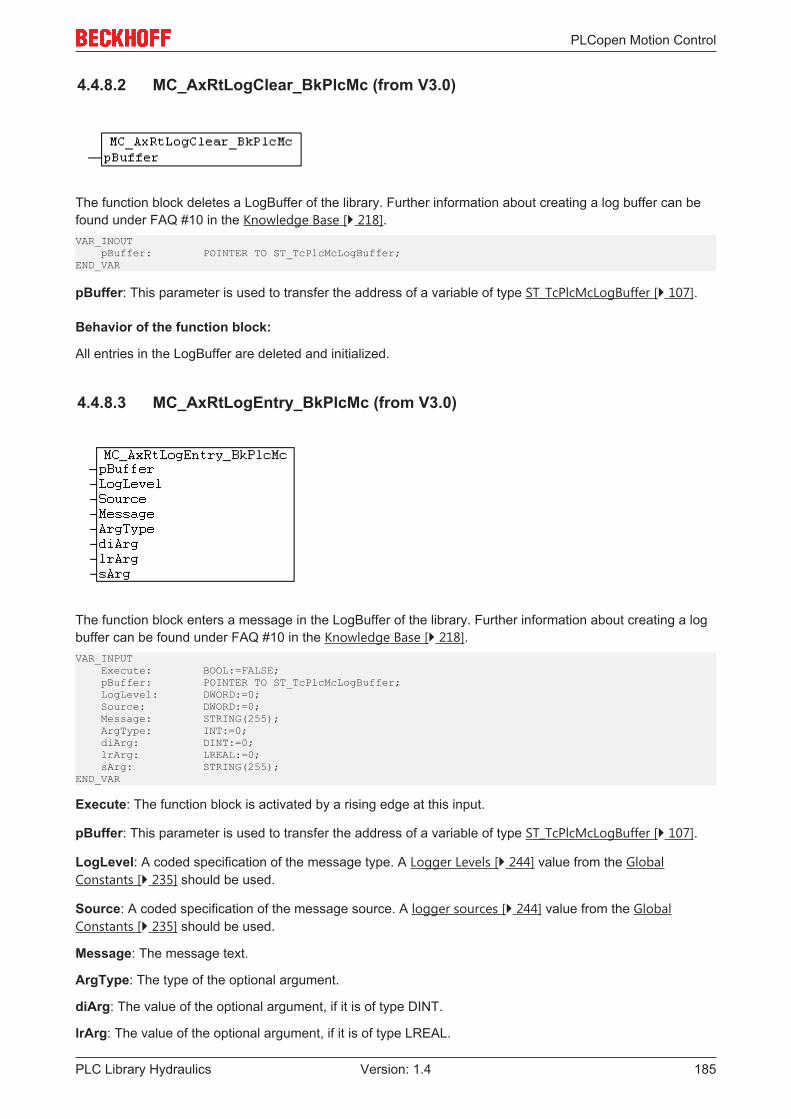
PLCopen Motion Control
PLC Library Hydraulics 185Version: 1.4
4.4.8.2 MC_AxRtLogClear_BkPlcMc (from V3.0)
The function block deletes a LogBuffer of the library. Further information about creating a log buffer can befound under FAQ #10 in the Knowledge Base [} 218].VAR_INOUT pBuffer: POINTER TO ST_TcPlcMcLogBuffer;END_VAR
pBuffer: This parameter is used to transfer the address of a variable of type ST_TcPlcMcLogBuffer [} 107].
Behavior of the function block:
All entries in the LogBuffer are deleted and initialized.
4.4.8.3 MC_AxRtLogEntry_BkPlcMc (from V3.0)
The function block enters a message in the LogBuffer of the library. Further information about creating a logbuffer can be found under FAQ #10 in the Knowledge Base [} 218].VAR_INPUT Execute: BOOL:=FALSE; pBuffer: POINTER TO ST_TcPlcMcLogBuffer; LogLevel: DWORD:=0; Source: DWORD:=0; Message: STRING(255); ArgType: INT:=0; diArg: DINT:=0; lrArg: LREAL:=0; sArg: STRING(255);END_VAR
Execute: The function block is activated by a rising edge at this input.
pBuffer: This parameter is used to transfer the address of a variable of type ST_TcPlcMcLogBuffer [} 107].
LogLevel: A coded specification of the message type. A Logger Levels [} 244] value from the GlobalConstants [} 235] should be used.
Source: A coded specification of the message source. A logger sources [} 244] value from the GlobalConstants [} 235] should be used.
Message: The message text.
ArgType: The type of the optional argument.
diArg: The value of the optional argument, if it is of type DINT.
lrArg: The value of the optional argument, if it is of type LREAL.

PLCopen Motion Control
PLC Library Hydraulics186 Version: 1.4
sArg: The value of the optional argument, if it is of type STRING.
Behaviour of the function block
If pBuffer was supplied correctly and points to an ST_TcPlcMcLogBuffer [} 107], which has capacity for atleast one further message, the transferred message data are complemented with local time information andentered in the message buffer.
4.4.8.4 MC_AxRtLoggerDeSpool_BkPlcMc (from V3.0)
The function block prevents overflowing of the LogBuffer of the library. Further information about creating alog buffer can be found under FAQ #10 in the Knowledge Base [} 218].VAR_INPUT Spare: INT;END_VARVAR_INOUT pBuffer: POINTER TO ST_TcPlcMcLogBuffer;END_VAR
Spare: The required number of free messages in the LogBuffer.
pBuffer: This parameter is used to transfer the address of a variable of type ST_TcPlcMcLogBuffer [} 107].
Behaviour of the function block
With each call the function block removes a message from the LogBuffer, if the number of free messages issmaller than the minimum number transferred in Spare. An MC_AxRtLoggerSpool_BkPlcMc [} 187] functionblock should be used to include the whole history in the Windows Event Viewer.
NOTE! Using this function block makes sense whenever a write-restricted mass storage medium isused (typically a FLASH DISK). As a minimum, a limited history of 10 to 15 messages is enabled.
4.4.8.5 MC_AxRtLoggerRead_BkPlcMc (from V3.0)
The function block reads a message from the LogBuffer of the library. Further information about creating alog buffer can be found under FAQ #10 in the Knowledge Base [} 218].
NOTE! This function block is used by diagnostics tools via ADS. A direct call from the PLCapplication generally makes no sense.VAR_INOUT Entry: INT:=0; pBuffer: POINTER TO ST_TcPlcMcLogBuffer; pEntry: POINTER TO ST_TcPlcMcLogEntry;END_VARVAR_OUTPUT Result: DWORD:=0;END_VAR
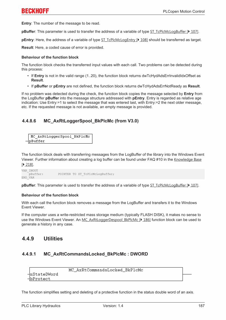
PLCopen Motion Control
PLC Library Hydraulics 187Version: 1.4
Entry: The number of the message to be read.
pBuffer: This parameter is used to transfer the address of a variable of type ST_TcPlcMcLogBuffer [} 107].
pEntry: Here, the address of a variable of type ST_TcPlcMcLogEntry [} 108] should be transferred as target.
Result: Here, a coded cause of error is provided.
Behaviour of the function block
The function block checks the transferred input values with each call. Two problems can be detected duringthis process:
• If Entry is not in the valid range (1..20), the function block returns dwTcHydAdsErrInvalidIdxOffset asResult.
• If pBuffer or pEntry are not defined, the function block returns dwTcHydAdsErrNotReady as Result.
If no problem was detected during the check, the function block copies the message selected by Entry fromthe LogBuffer pBuffer into the message structure addressed with pEntry. Entry is regarded as relative ageindication: Use Entry:=1 to select the message that was entered last, with Entry:=2 the next older message,etc. If the requested message is not available, an empty message is provided.
4.4.8.6 MC_AxRtLoggerSpool_BkPlcMc (from V3.0)
The function block deals with transferring messages from the LogBuffer of the library into the Windows EventViewer. Further information about creating a log buffer can be found under FAQ #10 in the Knowledge Base[} 218].VAR_INOUT pBuffer: POINTER TO ST_TcPlcMcLogBuffer;END_VAR
pBuffer: This parameter is used to transfer the address of a variable of type ST_TcPlcMcLogBuffer [} 107].
Behaviour of the function block
With each call the function block removes a message from the LogBuffer and transfers it to the WindowsEvent Viewer.
If the computer uses a write-restricted mass storage medium (typically FLASH DISK), it makes no sense touse the Windows Event Viewer. An MC_AxRtLoggerDespool_BkPlcMc [} 186] function block can be used togenerate a history in any case.
4.4.9 Utilities
4.4.9.1 MC_AxRtCommandsLocked_BkPlcMc : DWORD
The function simplifies setting and deleting of a protective function in the status double word of an axis.

PLCopen Motion Control
PLC Library Hydraulics188 Version: 1.4
VAR_INPUT nStateDWord: DWORD:=0; bProtect: BOOL:=FALSE;END_VAR
nStateDWord: The current state of the status double word.
bProtect: The required state of the protective function.
Behaviour of the function
The function shows the status bit of the protective function in the transferred status double word, dependingon bProtect.
NOTE! The application must assign the result of the function to the status double word of the axis.
An https://infosys.beckhoff.com/content/1033/tcplcLibhydraulics30/Resources/pro/1599851275.pro isavailable.
4.4.9.2 Filters
4.4.9.2.1 MC_AxUtiAverageDerivative_BkPlcMc (from V3.0)
The function block determines the derivative of a value through numeric differentiation over more than onecycle.VAR_INPUT Input: LREAL:=0.0; MinIdx: DINT:=0; MaxIdx: DINT:=0; pBuffer: POINTER TO LREAL:=0;END_VARVAR_OUTPUT Output: LREAL:=0.0; Error: BOOL:=FALSE; ErrorID: UDINT:=0;END_VARVAR_INOUT Axis: Axis_Ref_BkPlcMc;END_VAR
Input: The raw value of the parameter to be filtered.
MinIdx: The index of the first filter buffer element to be used.
MaxIdx: The index of the last filter buffer element to be used.
pBuffer: The address of the first filter buffer element.
Axis: Here, the address of a variable of type Axis_Ref_BkPlcMc [} 67] should be transferred.
Output: The filtered value.
Error: This output indicates problems with the transferred parameters.
ErrorID: In the event of an error, coded information about the type of problem is reported here.
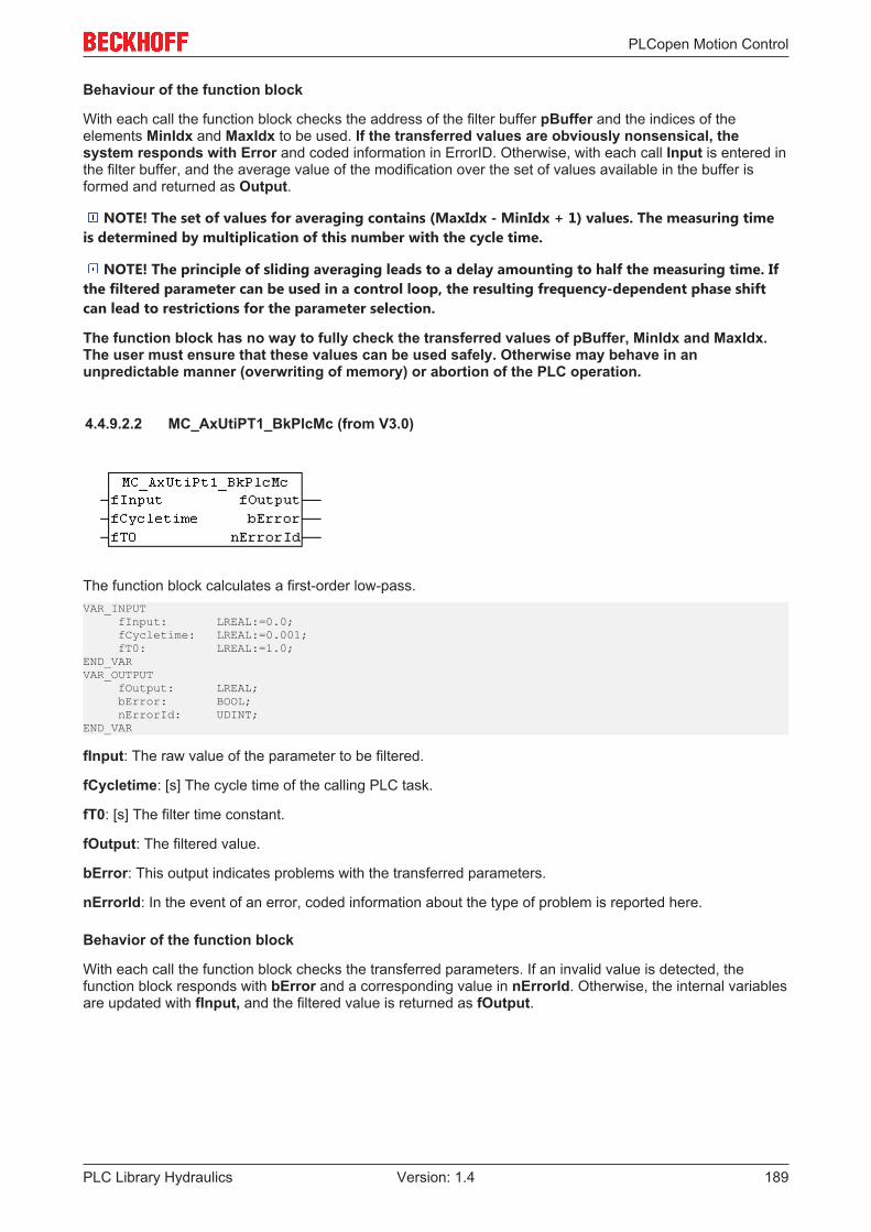
PLCopen Motion Control
PLC Library Hydraulics 189Version: 1.4
Behaviour of the function block
With each call the function block checks the address of the filter buffer pBuffer and the indices of theelements MinIdx and MaxIdx to be used. If the transferred values are obviously nonsensical, thesystem responds with Error and coded information in ErrorID. Otherwise, with each call Input is entered inthe filter buffer, and the average value of the modification over the set of values available in the buffer isformed and returned as Output.
NOTE! The set of values for averaging contains (MaxIdx - MinIdx + 1) values. The measuring timeis determined by multiplication of this number with the cycle time.
NOTE! The principle of sliding averaging leads to a delay amounting to half the measuring time. Ifthe filtered parameter can be used in a control loop, the resulting frequency-dependent phase shiftcan lead to restrictions for the parameter selection.
The function block has no way to fully check the transferred values of pBuffer, MinIdx and MaxIdx.The user must ensure that these values can be used safely. Otherwise may behave in anunpredictable manner (overwriting of memory) or abortion of the PLC operation.
4.4.9.2.2 MC_AxUtiPT1_BkPlcMc (from V3.0)
The function block calculates a first-order low-pass.VAR_INPUT fInput: LREAL:=0.0; fCycletime: LREAL:=0.001; fT0: LREAL:=1.0;END_VARVAR_OUTPUT fOutput: LREAL; bError: BOOL; nErrorId: UDINT;END_VAR
fInput: The raw value of the parameter to be filtered.
fCycletime: [s] The cycle time of the calling PLC task.
fT0: [s] The filter time constant.
fOutput: The filtered value.
bError: This output indicates problems with the transferred parameters.
nErrorId: In the event of an error, coded information about the type of problem is reported here.
Behavior of the function block
With each call the function block checks the transferred parameters. If an invalid value is detected, thefunction block responds with bError and a corresponding value in nErrorId. Otherwise, the internal variablesare updated with fInput, and the filtered value is returned as fOutput.
PLCopen Motion Control
PLC Library Hydraulics190 Version: 1.4
4.4.9.2.3 MC_AxUtiPT2_BkPlcMc (from V3.0)
The function block calculates a second-order low-pass.VAR_INPUT fInput: LREAL:=0.0; fCycletime: LREAL:=0.001; fTheta: LREAL:=1.0; fT0: LREAL:=1.0;END_VARVAR_OUTPUT fOutput: LREAL; bError: BOOL; nErrorId: UDINT;END_VAR
fInput: The raw value of the parameter to be filtered.
fCycletime: [s] The cycle time of the calling PLC task.
fTheta: The attenuation.
fT0: The filter time constant.
fOutput: The filtered value.
bError: This output indicates problems with the transferred parameters.
nErrorId: In the event of an error, coded information about the type of problem is reported here.
Behavior of the function block
With each call the function block checks the transferred parameters. If an invalid value is detected, thefunction block responds with bError and a corresponding value in nErrorId. Otherwise, the internal variablesare updated with fInput, and the filtered value is returned as fOutput.
4.4.9.2.4 MC_AxUtiSlewRateLimitter_BkPlcMc (from V3.0)
The function block generates a rise-limited ramp.VAR_INPUT fInput: LREAL:=0.0; fCycletime: DINT:=0; fMaxRate: DINT:=0;END_VARVAR_OUTPUT fOutput: LREAL:=0.0; bError: BOOL:=FALSE; nErrorId: UDINT:=0;END_VAR
fInput: The raw value of the parameter to be filtered.
fCycletime: [s] The cycle time of the calling PLC task in seconds.

PLCopen Motion Control
PLC Library Hydraulics 191Version: 1.4
fMaxRate: The magnitude of the maximum permitted rate of change at the output as change per second.
fOutput: [1/s] The filtered value.
bError: This output indicates problems with the transferred parameters.
nErrorId: In the event of an error, coded error information is output here.
Behavior of the function block
With each call the function block checks the transferred values for fCycletime and fMaxRate. If the valuesare incorrect, the system responds with bError and coded information in nErrorId. Otherwise, the differencebetween Input and Output is determined with each call. If the magnitude of this difference is less than orequal to fMaxRate * fCycletime, the value of Input is used directly as fOutput. Otherwise, fOutput ischanged by fMaxRate * fMaxRate. The sign is selected automatically.
NOTE! The value for fCycletime must be ≥ 0.001. Negative values are not permitted for fMaxRate.
Input will usually be a value, which is determined and filtered based on the cycle of the axis blocks.Axis_Ref_BkPlcMc [} 67].ST_TcHydAxParam [} 93].fCycletime can be used for fCycletime here.
4.4.9.2.5 MC_AxUtiSlidingAverage_BkPlcMc (from V3.0)
The function block determines a moving average.VAR_INPUT Input: LREAL:=0.0; MinIdx: DINT:=0; MaxIdx: DINT:=0; pBuffer: POINTER TO LREAL:=0;END_VARVAR_OUTPUT Output: LREAL:=0.0;END_VAR
Input: The raw value of the parameter to be filtered.
MinIdx: The index of the first filter buffer element to be used.
MaxIdx: The index of the last filter buffer element to be used.
pBuffer: The address of the first filter buffer element.
Output: The filtered value.
Behaviour of the function block
With each call the function block checks the address of the filter buffer pBuffer and the indices of theelements MinIdx and MaxIdx to be used. If the transferred values are obviously nonsensical, Input is outputas Output. Otherwise, with each call Input is entered in the filter buffer, and the average value of the set ofvalues available in the buffer is formed and returned as Output.
Note
The set of values for averaging contains (MaxIdx - MinIdx + 1) values. The filter time is de-termined by multiplication of this number with the cycle time.
PLCopen Motion Control
PLC Library Hydraulics192 Version: 1.4
NOTE! The principle of sliding averaging leads to a delay amounting to half the filter time. If thefiltered parameter can be used in a control loop, the resulting frequency-dependent phase shift canlead to restrictions for the parameter selection.
NOTE! The function block has no way to fully check the transferred values of pBuffer, MinIdx andMaxIdx. The user must ensure that these values can be used safely. Otherwise may behave in anunpredictable manner (overwriting of memory) or abortion of the PLC operation.
4.4.9.3 Identification
4.4.9.3.1 MC_AxUtiAutoIdent_BkPlcMc (from V3.0.28)
The function block automatic determines a number of axis parameters.VAR_INPUT Execute: BOOL;END_VARVAR_OUTPUT Busy: BOOL; Done: BOOL; Error: BOOL; ErrorID: UDINT;END_VARVAR_INOUT Axis: Axis_Ref_BkPlcMc;END_VAR
Execute: A positive edge at this input triggers the identification.
Busy: Indicates that a command is being processed.
Done: This indicates successful identification.
Error: The occurrence of an error is indicated here.
ErrorID: An encoded indication of the cause of the error is provided here.
Axis: Here, the address of a variable of type Axis_Ref_BkPlcMc [} 67] should be transferred.
Behavior of the function block
The function block checks whether the pointer Axis_Ref_BkPlcMc [} 67].pStAxAutoParams was initialized. Ifthis is the case, it performs a number of initializations when a positive edge is detected at the Execute inputand then commences the parameter identification. The individual steps of the identification are determinedby the values in ST_TcMcAutoIdent [} 93].
EnableEndOfTravel: If this boolean parameter is set, the mechanical travel limits are determinedautomatically. First, the system ensures that the axis can move freely or is at the positive function block. Theaxis is now moved with a negative control voltage until it has reached the function block. The axis is thenoperated with a positive control voltage until the positive function block has been detected. The controlvoltage is limited to EndOfTravel_NegativLimit and EndOfTravel_PositivLimit. If the positive travel limitfalls below the negative limit, the values are swapped, and Axis.stAxParams.bDrive_Reversed is inverted.

PLCopen Motion Control
PLC Library Hydraulics 193Version: 1.4
EnableOverlap, EnableZeroAdjust: If one of these boolean parameter is set, the cover or the offset voltageof the valve is determined. NOTE! Thus operation is influenced by EndOfTravel_Negative andEndOfTravel_Positive.
First, the axis is moved into a position window that is located in the middle between EndOfTravel_Positiveand EndOfTravel_Negative. The width of the window is 80% of the area defined by these parameters. Theoutput polarity of the drive is inverted, if required. Now, the output voltage is determined, at which the axisstarts moving in positive direction. Then, the corresponding negative voltage is determined. By offsettingthese parameter, both the cover and the offset voltage are determined. The type of entry in the axisparameter is controlled through EnableOverlap and EnableZeroAdjust.
EnableArreaRatio: If this boolean parameter is set, the direction-dependent velocity ratio is determined.First, the axis is moved into a position window, which is located in the middle between pStAxAutoParams.EndOfTravel_Positiv and pStAxAutoParams. EndOfTravel_Negativ. The width of the window is 80% of thearea defined by these parameters. Then, the axis is moved in positive and negative direction for one secondwith a control voltage of 1 V. The velocities determined during this movement are divided, in order todetermine the velocity ratio.
EndOfTravel_Negativ: [mm] If determination of the travel limits is activated, this value is determined by thefunction block. If it is disabled, the application must specify the value here. NOTE! This parameterinfluences the determination of the offset voltage and the area ratio.
EndOfTravel_Positiv: [mm] If determination of the travel limits is activated, this value is determined by thefunction block. If it is disabled, the application must specify the value here. NOTE! This parameterinfluences the determination of the offset voltage and the area ratio.
EndOfIncrements_Negativ: [1] If determination of the travel limits is activated, this value is determined bythe function block. It then matches EndOfTravel_Negativ, but it is the raw encoder value in increments.
EndOfIncrements_Positiv: [1] If determination of the travel limits is activated, this value is determined bythe function block. It then matches EndOfTravel_Positiv, but it is the raw encoder value in increments.
EndOfTravel_NegativLimit: [V] This parameter limits negative output voltages.
EndOfTravel_PositivLimit: [V] This parameter limits positive output voltages.
EndOfTravel_PositivDone: This signal is set by the function block, if determination of the travel limits isdisabled or the positive travel limit was determined.
EndOfTravel_NegativDone: This signal is set by the function block, if determination of the travel limits isdisabled or the negative travel limit was determined.
EndOfVelocity_NegativLimit: [mm/s] This parameter limits negative velocities. If this velocity is reached orexceeded during the measurement, the current measurement is completed, but no further measurement inthis direction is performed.
EndOfVelocity_PositivLimit: [mm/s] This parameter limits positive velocities. If this velocity is reached orexceeded during the measurement, the current measurement is completed, but no further measurement inthis direction is performed.
DecelerationFactor: [1] After the measuring stroke, the axis is moved to the end of the measuring path forthe next measuring stroke. The regular axis parameter fMaxAcc and fMaxDec, which are weighted with thisfactor, are used.
EnableValveCharacteristic: If this boolean parameter is set, the characteristic velocity curve is determinedautomatically.
ValveCharacteristicTable: This ARRAY[1..2,1..100] contains the value pairs of the linearization table.ValveCharacteristicTable[nnn,1] is the normalized velocity value, ValveCharacteristicTable[nnn,2] is thenormalized output value. Within the table, the value pairs with increasing index have increasing values forthe velocity value and the output value. The first value pair therefore describes the fastest negative point, thelast active value pair the fastest positive point. During automatic determination, the control voltage is limitedto EndOfTravel_NegativLimit and EndOfTravel_PositivLimit and the velocity toEndOfVelocity_NegativLimit and EndOfVelocity_PositivLimit. The further points of the table aredetermined through extrapolation from the last two data points.
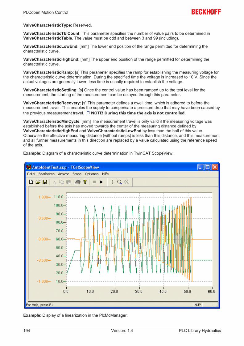
PLCopen Motion Control
PLC Library Hydraulics194 Version: 1.4
ValveCharacteristicType: Reserved.
ValveCharacteristicTblCount: This parameter specifies the number of value pairs to be determined inValveCharacteristicTable. The value must be odd and between 3 and 99 (including).
ValveCharacteristicLowEnd: [mm] The lower end position of the range permitted for determining thecharacteristic curve.
ValveCharacteristicHighEnd: [mm] The upper end position of the range permitted for determining thecharacteristic curve.
ValveCharacteristicRamp: [s] This parameter specifies the ramp for establishing the measuring voltage forthe characteristic curve determination. During the specified time the voltage is increased to 10 V. Since theactual voltages are generally lower, less time is usually required to establish the voltage.
ValveCharacteristicSettling: [s] Once the control value has been ramped up to the test level for themeasurement, the starting of the measurement can be delayed through this parameter.
ValveCharacteristicRecovery: [s] This parameter defines a dwell time, which is adhered to before themeasurement travel. This enables the supply to compensate a pressure drop that may have been caused bythe previous measurement travel. NOTE! During this time the axis is not controlled.
ValveCharacteristicMinCycle: [mm] The measurement travel is only valid if the measuring voltage wasestablished before the axis has moved towards the center of the measuring distance defined byValveCharacteristicHighEnd and ValveCharacteristicLowEnd by less than the half of this value.Otherwise the effective measuring distance (without ramps) is less than this distance, and this measurementand all further measurements in this direction are replaced by a value calculated using the reference speedof the axis.
Example: Diagram of a characteristic curve determination in TwinCAT ScopeView:
Example: Display of a linearization in the PlcMcManager:
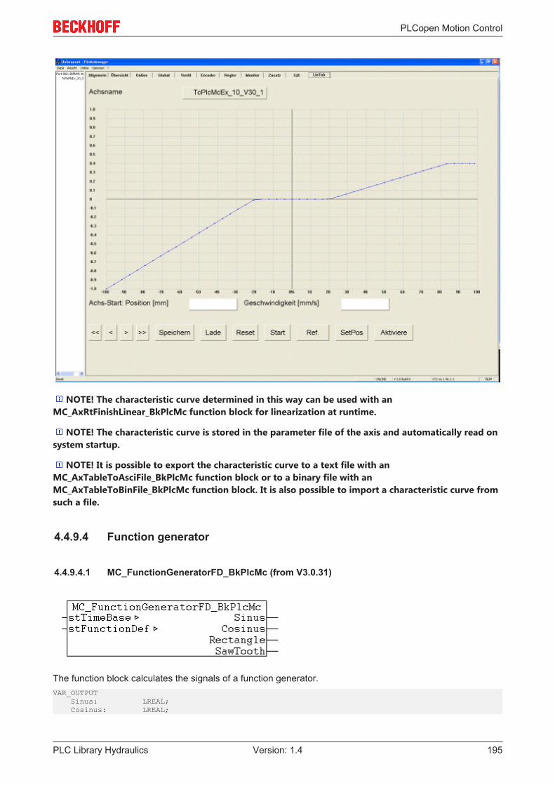
PLCopen Motion Control
PLC Library Hydraulics 195Version: 1.4
NOTE! The characteristic curve determined in this way can be used with anMC_AxRtFinishLinear_BkPlcMc function block for linearization at runtime.
NOTE! The characteristic curve is stored in the parameter file of the axis and automatically read onsystem startup.
NOTE! It is possible to export the characteristic curve to a text file with anMC_AxTableToAsciFile_BkPlcMc function block or to a binary file with anMC_AxTableToBinFile_BkPlcMc function block. It is also possible to import a characteristic curve fromsuch a file.
4.4.9.4 Function generator
4.4.9.4.1 MC_FunctionGeneratorFD_BkPlcMc (from V3.0.31)
The function block calculates the signals of a function generator.VAR_OUTPUT Sinus: LREAL; Cosinus: LREAL;

PLCopen Motion Control
PLC Library Hydraulics196 Version: 1.4
Rectangle: LREAL; SawTooth: LREAL;END_VARVAR_INOUT stTimeBase: ST_FunctionGeneratorTB_BkPlcMc; stFunctionDef: ST_FunctionGeneratorFD_BkPlcMc;END_VAR
Sinus, Cosinus, Rectangle, SawTooth: The output signals of the function generator.
stTimeBase: A structure with the parameters of the time base of this function generator.
stFunctionDef: A structure with the definitions of the output signals of a function generator.
Behaviour of the function block
The output signals are determined from stTime base.CurrentRatio and the parameters in stFunctionDef[} 92].
The time base in stTimeBase should be updated with an MC_FunctionGeneratorTB_BkPlcMc [} 161]()function block.
To change the operating frequency, an MC_FunctionGeneratorSetFrq_BkPlcMc [} 160]() function block shouldbe used.
4.4.9.4.2 MC_FunctionGeneratorSetFrq_BkPlcMc (from V3.0.31)
The function block updates the operating frequency of a time base for one or several function generators[} 159].VAR_INPUT Frequency: LREAL; CycleTime: LREAL;END_VARVAR_INOUT stTimeBase: ST_FunctionGeneratorTB_BkPlcMc;END_VAR
Frequency: The operating frequency to be used.
CycleTime: The cycle time of the calling task.
stTimeBase: A structure with the parameters of the time base of one or several function generators.
Behaviour of the function block
The function block sets stTimeBase.Frequency to the transferred value. stTimeBase.CurrentTime isadjusted, if required.
The function block uses stTimeBase.Freeze to prevent a collision with MC_FunctionGeneratorTB_BkPlcMc[} 161]() function blocks. Thus, it can also be called from another task.

PLCopen Motion Control
PLC Library Hydraulics 197Version: 1.4
4.4.9.4.3 MC_FunctionGeneratorTB_BkPlcMc (from V3.0.31)
The function block updates a time base for one or several function generators [} 159].VAR_INPUT CycleTime: LREAL;END_VARVAR_INOUT stTimeBase: ST_FunctionGeneratorTB_BkPlcMc;END_VAR
CycleTime: The cycle time of the calling task.
stTimeBase: A structure with the parameters of the time base of one or several function generators.
Behaviour of the function block
If stTimeBase.Freeze is not set, stTimeBase.CurrentTime is updated with CycleTime andstTimeBase.CurrentRatio is determined. stTimeBase.Frequency is taken into account.
To change the operating frequency, an MC_FunctionGeneratorSetFrq_BkPlcMc [} 160]() function block shouldbe used.
4.4.9.5 MC_AxUtiOffsetLatch_BkPlcMc (ab V3.0.40)
The function block updates the offset compensation.VAR_INPUT Execute: BOOL; OffsetLimit: LREAL:=0.5;END_VARVAR_OUTPUT Done: BOOL; Error: BOOL; ErrorId: UDINT; Latched: BOOL; Offset: LREAL;END_VARVAR_IN_OUT Axis: AXIS_REF_BkPlcMc;END_VAR
Execute: A positive edge triggers the update.
OffsetLimit: [V] The maximum permissible value range for the offset compensation.
Done: A successful update is indicated here.
Error: This output indicates any problems that may have occurred.
ErrorId: In the event of an error, coded information about the type of problem is reported here.
Latched: This output signals that the update was successfully completed.

PLCopen Motion Control
PLC Library Hydraulics198 Version: 1.4
Offset: [V] This output reports the offset value. It is only accepted as a new compensation when Done.
Behavior of the function block
With a positive edge at Execute, Offset is updated with the current output of the position controller.
Before accepting this value as compensation, the function block checks for several possible errors:
• The axis must have a controller enable and must not be in an active motion state or error state(Axis.stAxRtData.iCurrentStep=iTcHydStateIdle). (error code dwTcHydAdsErrBusy)
• The detected controller output must not be outside ±OffsetLimit. (error codedwTcHydAdsErrIllegalValue)
If one of the errors has occurred, Error is reported and ErrorId is assigned the specified error code. In thiscase, the compensation remains unchanged.
Otherwise, offset is applied as the new compensation value. Since from this point in time the part of theoutput value previously provided by the position controller is taken over by the compensation, the output ofthe controller must be canceled. The following steps are carried out once only:
• The set and current target positions are updated with the actual position.• The position error (lag error) is set to zero.• The position controller output is set to zero.• The I component of the default position controller is wiped.• If a position controller other than the default position controller is used, its I component must be deleted
by the application.
All outputs are set to the idle state with a negative edge at Execute.
4.5 Parameter
4.5.1 MC_AxAdsCommServer_BkPlcMc (from V3.0)
The function block gives the application the capacity to function as an ADS server. Calls function blocks oftype MC_AxAdsReadDecoder_BkPlcMc [} 200] and MC_AxAdsWriteDecoder_BkPlcMc [} 201] as required.The ADS codes [} 242] are listed in the Knowledge Base.VAR_INPUT nFirstAxisIndex: INT; nLastAxisIndex: INT;END_VARVAR_INOUT pAxItf: POINTER TO Axis_Ref_BkPlcMc;END_VAR
nFirstAxisIndex, nLastAxisIndex: This parameter is used to specify the dimensioning of theAxis_Ref_BkPlcMc [} 67] array.
Attention
Crash of the PLC application An incorrect specification at this point excludes some of the axes from the communicationor results in a crash of the PLC application by triggering serious runtime errors (PageFault Exception).
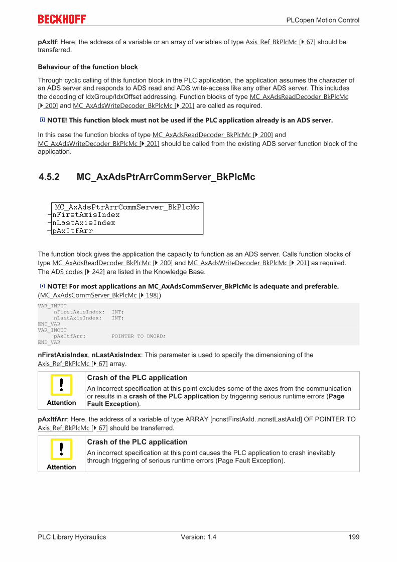
PLCopen Motion Control
PLC Library Hydraulics 199Version: 1.4
pAxItf: Here, the address of a variable or an array of variables of type Axis_Ref_BkPlcMc [} 67] should betransferred.
Behaviour of the function block
Through cyclic calling of this function block in the PLC application, the application assumes the character ofan ADS server and responds to ADS read and ADS write-access like any other ADS server. This includesthe decoding of IdxGroup/IdxOffset addressing. Function blocks of type MC_AxAdsReadDecoder_BkPlcMc[} 200] and MC_AxAdsWriteDecoder_BkPlcMc [} 201] are called as required.
NOTE! This function block must not be used if the PLC application already is an ADS server.
In this case the function blocks of type MC_AxAdsReadDecoder_BkPlcMc [} 200] andMC_AxAdsWriteDecoder_BkPlcMc [} 201] should be called from the existing ADS server function block of theapplication.
4.5.2 MC_AxAdsPtrArrCommServer_BkPlcMc
The function block gives the application the capacity to function as an ADS server. Calls function blocks oftype MC_AxAdsReadDecoder_BkPlcMc [} 200] and MC_AxAdsWriteDecoder_BkPlcMc [} 201] as required.The ADS codes [} 242] are listed in the Knowledge Base.
NOTE! For most applications an MC_AxAdsCommServer_BkPlcMc is adequate and preferable.(MC_AxAdsCommServer_BkPlcMc [} 198])VAR_INPUT nFirstAxisIndex: INT; nLastAxisIndex: INT;END_VARVAR_INOUT pAxItfArr: POINTER TO DWORD;END_VAR
nFirstAxisIndex, nLastAxisIndex: This parameter is used to specify the dimensioning of theAxis_Ref_BkPlcMc [} 67] array.
Attention
Crash of the PLC applicationAn incorrect specification at this point excludes some of the axes from the communicationor results in a crash of the PLC application by triggering serious runtime errors (PageFault Exception).
pAxItfArr: Here, the address of a variable of type ARRAY [ncnstFirstAxId..ncnstLastAxId] OF POINTER TOAxis_Ref_BkPlcMc [} 67] should be transferred.
Attention
Crash of the PLC applicationAn incorrect specification at this point causes the PLC application to crash inevitablythrough triggering of serious runtime errors (Page Fault Exception).

PLCopen Motion Control
PLC Library Hydraulics200 Version: 1.4
Behaviour of the function block
Through cyclic calling of this function block in the PLC application, the application assumes the character ofan ADS server and responds to ADS read and ADS write-access like any other ADS server. This includesthe decoding of IdxGroup/IdxOffset addressing. Function blocks of type MC_AxAdsReadDecoder_BkPlcMc[} 200] and MC_AxAdsWriteDecoder_BkPlcMc [} 201] are called as required.
NOTE! This function block must not be used if the PLC application already is an ADS server.
In this case the function blocks of type MC_AxAdsReadDecoder_BkPlcMc [} 200] andMC_AxAdsWriteDecoder_BkPlcMc [} 201] should be called from the existing ADS server function block of theapplication.
A program example [} 219] #16 is available.
4.5.3 MC_AxAdsReadDecoder_BkPlcMc (from V3.0)
The function block decodes ADS read accesses. The ADS codes [} 242] are listed in the Knowledge Base.VAR_INPUT nFirstAxisIndex: INT; nLastAxisIndex: INT; bReset: BOOL; bValid: BOOL; sNetId: STRING(80); nPort: UINT; nInvokeId: UDINT; nIdxGroup: UDINT; nIdxOffs: UDINT; cbReadLen: UDINT; pAxItf: POINTER TO Axis_Ref_BkPlcMc:=0;END_VARVAR_INOUT DeadManCount: UDINT;END_VARVAR_OUTPUT bClear: BOOL; bPending: BOOL;END_VAR
nFirstAxisIndex, nLastAxisIndex: This parameter is used to specify the dimensioning of theAxis_Ref_BkPlcMc [} 67] array.
CAUTION! An incorrect specification at this point excludes some of the axes from the communicationor results in a crash of the PLC application by triggering serious runtime errors (Page Fault Exception).
bReset, bValid: The signals are used to co-ordinate the decoder with the ADS server.
sNetId, nPort, nInvokeId: These values are required in order to generate the ADS response. They aresupplied by an ADS server's ADS indication function block.
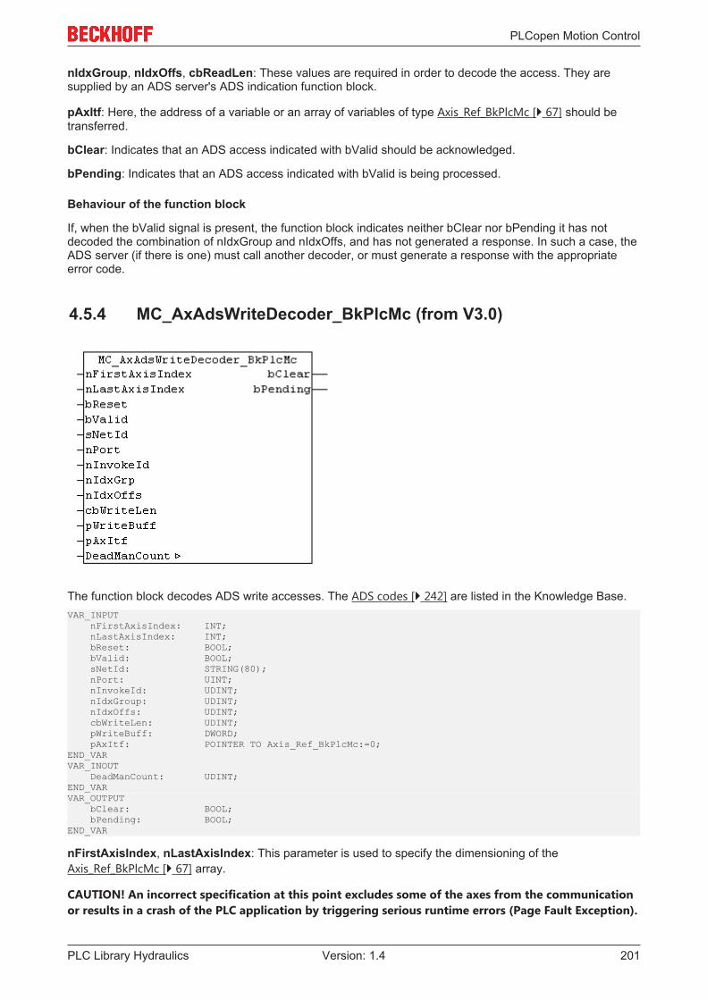
PLCopen Motion Control
PLC Library Hydraulics 201Version: 1.4
nIdxGroup, nIdxOffs, cbReadLen: These values are required in order to decode the access. They aresupplied by an ADS server's ADS indication function block.
pAxItf: Here, the address of a variable or an array of variables of type Axis_Ref_BkPlcMc [} 67] should betransferred.
bClear: Indicates that an ADS access indicated with bValid should be acknowledged.
bPending: Indicates that an ADS access indicated with bValid is being processed.
Behaviour of the function block
If, when the bValid signal is present, the function block indicates neither bClear nor bPending it has notdecoded the combination of nIdxGroup and nIdxOffs, and has not generated a response. In such a case, theADS server (if there is one) must call another decoder, or must generate a response with the appropriateerror code.
4.5.4 MC_AxAdsWriteDecoder_BkPlcMc (from V3.0)
The function block decodes ADS write accesses. The ADS codes [} 242] are listed in the Knowledge Base.VAR_INPUT nFirstAxisIndex: INT; nLastAxisIndex: INT; bReset: BOOL; bValid: BOOL; sNetId: STRING(80); nPort: UINT; nInvokeId: UDINT; nIdxGroup: UDINT; nIdxOffs: UDINT; cbWriteLen: UDINT; pWriteBuff: DWORD; pAxItf: POINTER TO Axis_Ref_BkPlcMc:=0;END_VARVAR_INOUT DeadManCount: UDINT;END_VARVAR_OUTPUT bClear: BOOL; bPending: BOOL;END_VAR
nFirstAxisIndex, nLastAxisIndex: This parameter is used to specify the dimensioning of theAxis_Ref_BkPlcMc [} 67] array.
CAUTION! An incorrect specification at this point excludes some of the axes from the communicationor results in a crash of the PLC application by triggering serious runtime errors (Page Fault Exception).
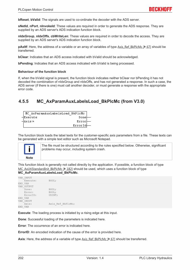
PLCopen Motion Control
PLC Library Hydraulics202 Version: 1.4
bReset, bValid: The signals are used to co-ordinate the decoder with the ADS server.
sNetId, nPort, nInvokeId: These values are required in order to generate the ADS response. They aresupplied by an ADS server's ADS indication function block.
nIdxGroup, nIdxOffs, cbWriteLen: These values are required in order to decode the access. They aresupplied by an ADS server's ADS indication function block.
pAxItf: Here, the address of a variable or an array of variables of type Axis_Ref_BkPlcMc [} 67] should betransferred.
bClear: Indicates that an ADS access indicated with bValid should be acknowledged.
bPending: Indicates that an ADS access indicated with bValid is being processed.
Behaviour of the function block
If, when the bValid signal is present, the function block indicates neither bClear nor bPending it has notdecoded the combination of nIdxGroup and nIdxOffs, and has not generated a response. In such a case, theADS server (if there is one) must call another decoder, or must generate a response with the appropriateerror code.
4.5.5 MC_AxParamAuxLabelsLoad_BkPlcMc (from V3.0)
The function block loads the label texts for the customer-specific axis parameters from a file. These texts canbe generated with a simple text editor such as Microsoft Notepad.
Note
The file must be structured according to the rules specified below. Otherwise, significantproblems may occur, including system crash.
This function block is generally not called directly by the application. If possible, a function block of typeMC_AxUtiStandardInit_BkPlcMc [} 182] should be used, which uses a function block of typeMC_AxParamAuxLabelsLoad_BkPlcMc.VAR_INPUT Execute: BOOL;END_VARVAR_OUTPUT Done: BOOL; Error: BOOL; ErrorID: UDINT;END_VARVAR_INOUT Axis: Axis_Ref_BkPlcMc;END_VAR
Execute: The loading process is initiated by a rising edge at this input.
Done: Successful loading of the parameters is indicated here.
Error: The occurrence of an error is indicated here.
ErrorID: An encoded indication of the cause of the error is provided here.
Axis: Here, the address of a variable of type Axis_Ref_BkPlcMc [} 67] should be transferred.
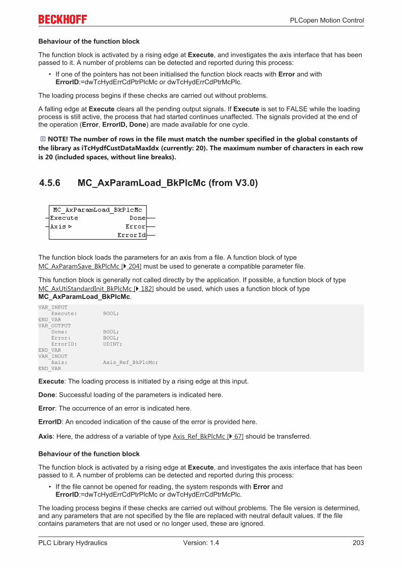
PLCopen Motion Control
PLC Library Hydraulics 203Version: 1.4
Behaviour of the function block
The function block is activated by a rising edge at Execute, and investigates the axis interface that has beenpassed to it. A number of problems can be detected and reported during this process:
• If one of the pointers has not been initialised the function block reacts with Error and withErrorID:=dwTcHydErrCdPtrPlcMc or dwTcHydErrCdPtrMcPlc.
The loading process begins if these checks are carried out without problems.
A falling edge at Execute clears all the pending output signals. If Execute is set to FALSE while the loadingprocess is still active, the process that had started continues unaffected. The signals provided at the end ofthe operation (Error, ErrorID, Done) are made available for one cycle.
NOTE! The number of rows in the file must match the number specified in the global constants ofthe library as iTcHydfCustDataMaxIdx (currently: 20). The maximum number of characters in each rowis 20 (included spaces, without line breaks).
4.5.6 MC_AxParamLoad_BkPlcMc (from V3.0)
The function block loads the parameters for an axis from a file. A function block of typeMC_AxParamSave_BkPlcMc [} 204] must be used to generate a compatible parameter file.
This function block is generally not called directly by the application. If possible, a function block of typeMC_AxUtiStandardInit_BkPlcMc [} 182] should be used, which uses a function block of typeMC_AxParamLoad_BkPlcMc.VAR_INPUT Execute: BOOL;END_VARVAR_OUTPUT Done: BOOL; Error: BOOL; ErrorID: UDINT;END_VARVAR_INOUT Axis: Axis_Ref_BkPlcMc;END_VAR
Execute: The loading process is initiated by a rising edge at this input.
Done: Successful loading of the parameters is indicated here.
Error: The occurrence of an error is indicated here.
ErrorID: An encoded indication of the cause of the error is provided here.
Axis: Here, the address of a variable of type Axis_Ref_BkPlcMc [} 67] should be transferred.
Behaviour of the function block
The function block is activated by a rising edge at Execute, and investigates the axis interface that has beenpassed to it. A number of problems can be detected and reported during this process:
• If the file cannot be opened for reading, the system responds with Error andErrorID:=dwTcHydErrCdPtrPlcMc or dwTcHydErrCdPtrMcPlc.
The loading process begins if these checks are carried out without problems. The file version is determined,and any parameters that are not specified by the file are replaced with neutral default values. If the filecontains parameters that are not used or no longer used, these are ignored.
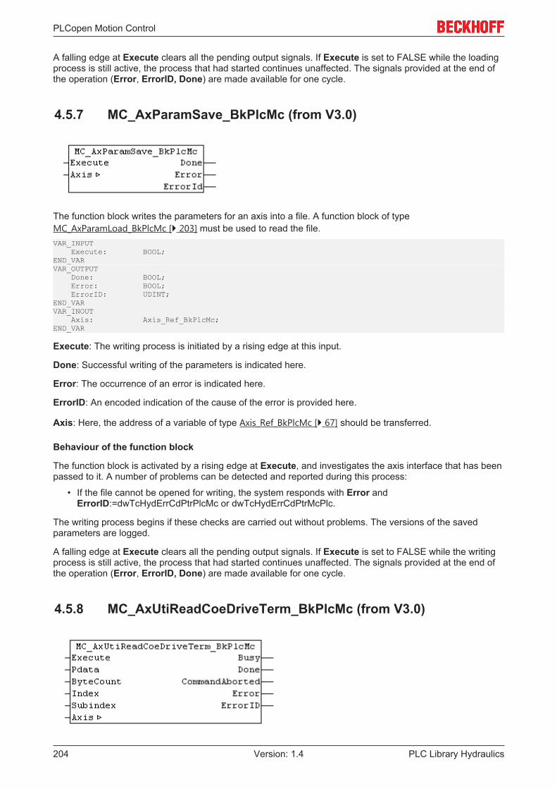
PLCopen Motion Control
PLC Library Hydraulics204 Version: 1.4
A falling edge at Execute clears all the pending output signals. If Execute is set to FALSE while the loadingprocess is still active, the process that had started continues unaffected. The signals provided at the end ofthe operation (Error, ErrorID, Done) are made available for one cycle.
4.5.7 MC_AxParamSave_BkPlcMc (from V3.0)
The function block writes the parameters for an axis into a file. A function block of typeMC_AxParamLoad_BkPlcMc [} 203] must be used to read the file.VAR_INPUT Execute: BOOL;END_VARVAR_OUTPUT Done: BOOL; Error: BOOL; ErrorID: UDINT;END_VARVAR_INOUT Axis: Axis_Ref_BkPlcMc;END_VAR
Execute: The writing process is initiated by a rising edge at this input.
Done: Successful writing of the parameters is indicated here.
Error: The occurrence of an error is indicated here.
ErrorID: An encoded indication of the cause of the error is provided here.
Axis: Here, the address of a variable of type Axis_Ref_BkPlcMc [} 67] should be transferred.
Behaviour of the function block
The function block is activated by a rising edge at Execute, and investigates the axis interface that has beenpassed to it. A number of problems can be detected and reported during this process:
• If the file cannot be opened for writing, the system responds with Error andErrorID:=dwTcHydErrCdPtrPlcMc or dwTcHydErrCdPtrMcPlc.
The writing process begins if these checks are carried out without problems. The versions of the savedparameters are logged.
A falling edge at Execute clears all the pending output signals. If Execute is set to FALSE while the writingprocess is still active, the process that had started continues unaffected. The signals provided at the end ofthe operation (Error, ErrorID, Done) are made available for one cycle.
4.5.8 MC_AxUtiReadCoeDriveTerm_BkPlcMc (from V3.0)

PLCopen Motion Control
PLC Library Hydraulics 205Version: 1.4
The function block reads the contents of a register from the EL terminal, which is used as drive interface forthe axis.VAR_INPUT Execute: BOOL; Pdata: POINTER TO BYTE:=0; ByteCount: BYTE:=0; Index: WORD:=0; Subindex: BYTE:=0;END_VARVAR_OUTPUT Busy: BOOL; Done: BOOL; CommandAborted: BOOL; Error: BOOL; ErrorID: UDINT;END_VARVAR_INOUT Axis: Axis_Ref_BkPlcMc;END_VAR
Execute: A rising edge at this input starts the read process.
Pdata: Here, the address of the variable is specified, in which the read value is to be output.
ByteCount: Here, the size of the variable is specified in bytes.
Index, Subindex: Here, the addressing of parameter in the terminal is specified.
Busy: Indicates that a command is being processed.
Done: Successful loading of the parameter is indicated here.
CommandAborted: Indicates abortion of the read operation.
Error: The occurrence of an error is indicated here.
ErrorID: An encoded indication of the cause of the error is provided here.
Axis: Here, the address of a variable of type Axis_Ref_BkPlcMc [} 67] should be transferred.
Behaviour of the function block
The function block is activated by a rising edge at Execute, and investigates the axis interface that has beenpassed to it. A number of problems can be detected and reported during this process:
• If the axis is enabled for operation, the system responds with Error andErrorID:=dwTcHydErrCdNotReady.
• If Index or Subindex are outside the permitted range, the system responds with Error andErrorID:=dwTcHydErrCdTblIllegalIndex.
• If ByteCount or Pdata are outside the permitted range, the system responds with Error andErrorID:=dwTcHydErrCdTblIllegalIndex.
• If an I/O module, which does not support parameter communication, is set as nDrive_Type in the axisparameters, the system responds with Error and ErrorID:=dwTcHydErrCdNotCompatible.
• If problems occur during the ADS communication with the terminal, the corresponding ADS error codeis returned as ErrorID, and Error is indicated. The following codes [} 236] may occur:
◦ 16#0006 = 6 = The port number of the ADS address used is invalid: Check the mapping of theInfoData element of the terminal!
◦ 16#0007 = 7 = The AmsNetID of the ADS address used is invalid: Check the mapping of theInfoData element of the terminal!
◦ 16#0702 = 1794 = dwTcHydAdsErrInvalidIdxGroup = The terminal does not support the CoEprotocol.
◦ 16#0703 = 1795 = dwTcHydAdsErrInvalidIdxOffset = The address in index and subindex is notsupported in the terminal.
◦ 16#0745 = 1861 = dwTcHydAdsErrTimeout = Timeout.

PLCopen Motion Control
PLC Library Hydraulics206 Version: 1.4
A falling edge at Execute clears all the pending output signals. If Execute is set to FALSE while the loadingprocess is still active, the process that had started continues unaffected. The signals at the end of theoperation (Done, CommandAborted, Error, ErrorID) are issued for one cycle.
4.5.9 MC_AxUtiReadCoeEncTerm_BkPlcMc (from V3.0)
The function block reads the contents of a register from the EL terminal, which is used as encoder interfacefor the axis.VAR_INPUT Execute: BOOL; Pdata: POINTER TO BYTE:=0; ByteCount: BYTE:=0; Index: WORD:=0; Subindex: BYTE:=0;END_VARVAR_OUTPUT Busy: BOOL; Done: BOOL; CommandAborted: BOOL; Error: BOOL; ErrorID: UDINT;END_VARVAR_INOUT Axis: Axis_Ref_BkPlcMc;END_VAR
Execute: A rising edge at this input starts the read process.
Pdata: Here, the address of the variable is specified, in which the read value is to be output.
ByteCount: Here, the size of the variable is specified in bytes.
Index, Subindex: Here, the addressing of parameter in the terminal is specified.
Busy: Indicates that a command is being processed.
Done: Successful loading of the parameter is indicated here.
CommandAborted: Indicates abortion of the read operation.
Error: The occurrence of an error is indicated here.
ErrorID: An encoded indication of the cause of the error is provided here.
Axis: Here, the address of a variable of type Axis_Ref_BkPlcMc [} 67] should be transferred.
Behaviour of the function block
The function block is activated by a rising edge at Execute, and investigates the axis interface that has beenpassed to it. A number of problems can be detected and reported during this process:
• If the axis is enabled for operation, the system responds with Error andErrorID:=dwTcHydErrCdNotReady.
• If Index or Subindex are outside the permitted range, the system responds with Error andErrorID:=dwTcHydErrCdTblIllegalIndex.
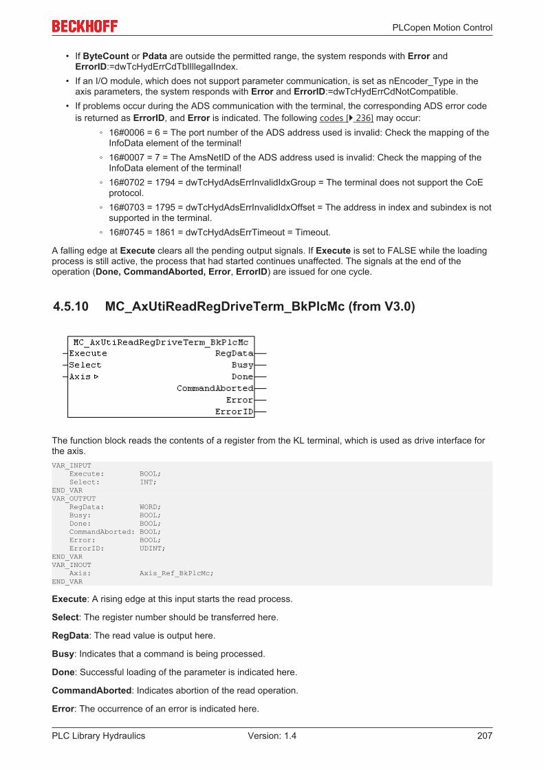
PLCopen Motion Control
PLC Library Hydraulics 207Version: 1.4
• If ByteCount or Pdata are outside the permitted range, the system responds with Error andErrorID:=dwTcHydErrCdTblIllegalIndex.
• If an I/O module, which does not support parameter communication, is set as nEncoder_Type in theaxis parameters, the system responds with Error and ErrorID:=dwTcHydErrCdNotCompatible.
• If problems occur during the ADS communication with the terminal, the corresponding ADS error codeis returned as ErrorID, and Error is indicated. The following codes [} 236] may occur:
◦ 16#0006 = 6 = The port number of the ADS address used is invalid: Check the mapping of theInfoData element of the terminal!
◦ 16#0007 = 7 = The AmsNetID of the ADS address used is invalid: Check the mapping of theInfoData element of the terminal!
◦ 16#0702 = 1794 = dwTcHydAdsErrInvalidIdxGroup = The terminal does not support the CoEprotocol.
◦ 16#0703 = 1795 = dwTcHydAdsErrInvalidIdxOffset = The address in index and subindex is notsupported in the terminal.
◦ 16#0745 = 1861 = dwTcHydAdsErrTimeout = Timeout.
A falling edge at Execute clears all the pending output signals. If Execute is set to FALSE while the loadingprocess is still active, the process that had started continues unaffected. The signals at the end of theoperation (Done, CommandAborted, Error, ErrorID) are issued for one cycle.
4.5.10 MC_AxUtiReadRegDriveTerm_BkPlcMc (from V3.0)
The function block reads the contents of a register from the KL terminal, which is used as drive interface forthe axis.VAR_INPUT Execute: BOOL; Select: INT;END_VARVAR_OUTPUT RegData: WORD; Busy: BOOL; Done: BOOL; CommandAborted: BOOL; Error: BOOL; ErrorID: UDINT;END_VARVAR_INOUT Axis: Axis_Ref_BkPlcMc;END_VAR
Execute: A rising edge at this input starts the read process.
Select: The register number should be transferred here.
RegData: The read value is output here.
Busy: Indicates that a command is being processed.
Done: Successful loading of the parameter is indicated here.
CommandAborted: Indicates abortion of the read operation.
Error: The occurrence of an error is indicated here.
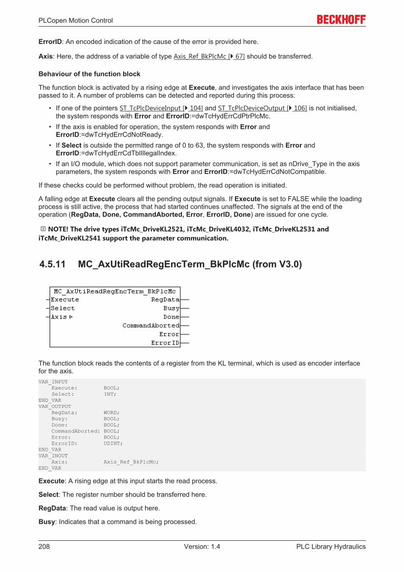
PLCopen Motion Control
PLC Library Hydraulics208 Version: 1.4
ErrorID: An encoded indication of the cause of the error is provided here.
Axis: Here, the address of a variable of type Axis_Ref_BkPlcMc [} 67] should be transferred.
Behaviour of the function block
The function block is activated by a rising edge at Execute, and investigates the axis interface that has beenpassed to it. A number of problems can be detected and reported during this process:
• If one of the pointers ST_TcPlcDeviceInput [} 104] and ST_TcPlcDeviceOutput [} 106] is not initialised,the system responds with Error and ErrorID:=dwTcHydErrCdPtrPlcMc.
• If the axis is enabled for operation, the system responds with Error andErrorID:=dwTcHydErrCdNotReady.
• If Select is outside the permitted range of 0 to 63, the system responds with Error andErrorID:=dwTcHydErrCdTblIllegalIndex.
• If an I/O module, which does not support parameter communication, is set as nDrive_Type in the axisparameters, the system responds with Error and ErrorID:=dwTcHydErrCdNotCompatible.
If these checks could be performed without problem, the read operation is initiated.
A falling edge at Execute clears all the pending output signals. If Execute is set to FALSE while the loadingprocess is still active, the process that had started continues unaffected. The signals at the end of theoperation (RegData, Done, CommandAborted, Error, ErrorID, Done) are issued for one cycle.
NOTE! The drive types iTcMc_DriveKL2521, iTcMc_DriveKL4032, iTcMc_DriveKL2531 andiTcMc_DriveKL2541 support the parameter communication.
4.5.11 MC_AxUtiReadRegEncTerm_BkPlcMc (from V3.0)
The function block reads the contents of a register from the KL terminal, which is used as encoder interfacefor the axis.VAR_INPUT Execute: BOOL; Select: INT;END_VARVAR_OUTPUT RegData: WORD; Busy: BOOL; Done: BOOL; CommandAborted: BOOL; Error: BOOL; ErrorID: UDINT;END_VARVAR_INOUT Axis: Axis_Ref_BkPlcMc;END_VAR
Execute: A rising edge at this input starts the read process.
Select: The register number should be transferred here.
RegData: The read value is output here.
Busy: Indicates that a command is being processed.

PLCopen Motion Control
PLC Library Hydraulics 209Version: 1.4
Done: Successful loading of the parameter is indicated here.
CommandAborted: Indicates abortion of the read operation.
Error: The occurrence of an error is indicated here.
ErrorID: An encoded indication of the cause of the error is provided here.
Axis: Here, the address of a variable of type Axis_Ref_BkPlcMc [} 67] should be transferred.
Behaviour of the function block
The function block is activated by a rising edge at Execute, and investigates the axis interface that has beenpassed to it. A number of problems can be detected and reported during this process:
• If one of the pointers ST_TcPlcDeviceInput [} 104] and ST_TcPlcDeviceOutput [} 106] is not initialised,the system responds with Error and ErrorID:=dwTcHydErrCdPtrPlcMc.
• If the axis is enabled for operation, the system responds with Error andErrorID:=dwTcHydErrCdNotReady.
• If Select is outside the permitted range of 0 to 63, the system responds with Error andErrorID:=dwTcHydErrCdTblIllegalIndex.
• If an I/O module, which does not support parameter communication, is set as nEncoder_Type in theaxis parameters, the system responds with Error and ErrorID:=dwTcHydErrCdNotCompatible.
If these checks could be performed without problem, the read operation is initiated.
A falling edge at Execute clears all the pending output signals. If Execute is set to FALSE while the loadingprocess is still active, the process that had started continues unaffected. The signals at the end of theoperation (RegData, Done, CommandAborted, Error, ErrorID, Done) are issued for one cycle.
NOTE! The drive types iTcMc_EncoderKL3002, iTcMc_EncoderKL3042, iTcMc_EncoderKL3062,iTcMc_EncoderKL3162, iTcMc_EncoderKL5101, iTcMc_EncoderKL5111, iTcMc_EncoderKL2521,iTcMc_EncoderKL2531 und iTcMc_EncoderKL2541 support parameter communication.
4.5.12 MC_AxUtiUpdateRegDriveTerm_BkPlcMc (from V3.0.7)
The function block writes a parameter set into the registers of a KL terminal. It usesMC_AxUtiReadRegDriveTerm_BkPlcMc [} 207] and MC_AxUtiWriteRegDriveTerm_BkPlcMc [} 215] functionblocks for this purpose.VAR_INPUT Execute: BOOL;END_VARVAR_OUTPUT Done: BOOL; Busy: BOOL; CommandAborted: BOOL; Error: BOOL; ErrorID: UDINT;END_VARVAR_INOUT Axis: Axis_Ref_BkPlcMc; RegData: ST_TcPlcRegDataTable;END_VAR
Execute: The writing process is initiated by a rising edge at this input.

PLCopen Motion Control
PLC Library Hydraulics210 Version: 1.4
RegData: Here, the address of parameter set should be specified, whose content is to be written into theterminal.
Axis: Here, the address of a variable of type Axis_Ref_BkPlcMc [} 67] should be transferred.
Done: Indicates successful writing of the parameter.
Busy: Indicates that a command is being processed.
CommandAborted: Indicates abortion of the read operation.
Error: The occurrence of an error is indicated here.
ErrorID: An encoded indication of the cause of the error is provided here.
Behavior of the function block:
The function block is activated by a rising edge at Execute, and investigates the axis interface that has beenpassed to it. A number of problems can be detected and reported during this process:
• If one of the pointers ST_TcPlcDeviceInput [} 104] and ST_TcPlcDeviceOutput [} 106] is not initialized,the system responds with Error and ErrorID:=dwTcHydErrCdPtrPlcMc.
• If the axis is enabled for operation, the system responds with Error andErrorID:=dwTcHydErrCdNotReady.
• If Select is outside the permitted range of 0 to 63, the system responds with Error andErrorID:=dwTcHydErrCdTblIllegalIndex.
• If an I/O module, which does not support parameter communication, is set as nDrive_Type in the axisparameters, the system responds with Error and ErrorID:=dwTcHydErrCdNotCompatible.
• The value in ST_TcPlcRegDataTable [} 109].RegDataItem[...].Access determines how the element istreated.
◦ 0: Element is ignored.◦ 1: The register addressed through Select is read. Its contents are compared with RegData. If
the contents differ, the write operation is aborted with Error and ErrorID:=16#FFFFFFFF.◦ 2: The register addressed through Select is read. Its contents are compared with RegData. If
the contents are not larger, the write operation is aborted with Error andErrorID:=16#FFFFFFFF.
◦ 3: The register addressed through Select is read. Its contents are compared with RegData. Ifthe contents are not smaller, the write operation is aborted with Error andErrorID:=16#FFFFFFFF.
◦ 4: The register addressed through Select is read. Its contents are compared with RegData. Ifthe contents are not larger or equal, the write operation is aborted with Error andErrorID:=16#FFFFFFFF.
◦ 5: The register addressed through Select is read. Its contents are compared with RegData. Ifthe contents are not smaller or equal, the write operation is aborted with Error andErrorID:=16#FFFFFFFF.
◦ 10: The register addressed through Select is written with RegData.◦ Other values are currently ignored. Future versions of the library may support additional
functions. An empty element should therefore always be identified with 0.
A falling edge at Execute clears all the pending output signals. If Execute is set to FALSE while the writingprocess is still active, the process that had started continues unaffected. The signals at the end of theoperation (Done, CommandAborted, Error, ErrorID) are issued for one cycle.

PLCopen Motion Control
PLC Library Hydraulics 211Version: 1.4
4.5.13 MC_AxUtiUpdateRegEncTerm_BkPlcMc (from V3.0.7)
The function block writes a parameter set into the registers of a KL terminal. It usesMC_AxUtiReadRegDriveTerm_BkPlcMc [} 208] and MC_AxUtiWriteRegDriveTerm_BkPlcMc [} 216] functionblocks for this purpose.VAR_INPUT Execute: BOOL;END_VARVAR_OUTPUT Done: BOOL; Busy: BOOL; CommandAborted: BOOL; Error: BOOL; ErrorID: UDINT;END_VARVAR_INOUT Axis: Axis_Ref_BkPlcMc; RegData: ST_TcPlcRegDataTable;END_VAR
Execute: The writing process is initiated by a rising edge at this input.
RegData: Here, the address of parameter set should be specified, whose content is to be written into theterminal.
Axis: Here, the address of a variable of type Axis_Ref_BkPlcMc [} 67] should be transferred.
Done: Indicates successful writing of the parameter.
Busy: Indicates that a command is being processed.
CommandAborted: Indicates abortion of the read operation.
Error: The occurrence of an error is indicated here.
ErrorID: An encoded indication of the cause of the error is provided here.
Behaviour of the function block
The function block is activated by a rising edge at Execute, and investigates the axis interface that has beenpassed to it. A number of problems can be detected and reported during this process:
• If one of the pointers ST_TcPlcDeviceInput [} 104] and ST_TcPlcDeviceOutput [} 106] is not initialised,the system responds with Error and ErrorID:=dwTcHydErrCdPtrPlcMc.
• If the axis is enabled for operation, the system responds with Error andErrorID:=dwTcHydErrCdNotReady.
• If Select is outside the permitted range of 0 to 63, the system responds with Error andErrorID:=dwTcHydErrCdTblIllegalIndex.
• If an I/O module, which does not support parameter communication, is set as nDrive_Type in the axisparameters, the system responds with Error and ErrorID:=dwTcHydErrCdNotCompatible.
• The value in ST_TcPlcRegDataTable [} 109].RegDataItem[...].Access determines how the element istreated.
◦ 0: Element is ignored.◦ 1: The register addressed through Select is read. Its contents are compared with RegData. If
the contents differ, the write operation is aborted with Error and ErrorID:=16#FFFFFFFF.

PLCopen Motion Control
PLC Library Hydraulics212 Version: 1.4
◦ 2: The register addressed through Select is read. Its contents are compared with RegData. Ifthe contents are not larger, the write operation is aborted with Error andErrorID:=16#FFFFFFFF.
◦ 3: The register addressed through Select is read. Its contents are compared with RegData. Ifthe contents are not smaller, the write operation is aborted with Error andErrorID:=16#FFFFFFFF.
◦ 4: The register addressed through Select is read. Its contents are compared with RegData. Ifthe contents are not larger or equal, the write operation is aborted with Error andErrorID:=16#FFFFFFFF.
◦ 5: The register addressed through Select is read. Its contents are compared with RegData. Ifthe contents are not smaller or equal, the write operation is aborted with Error andErrorID:=16#FFFFFFFF.
◦ 10: The register addressed through Select is written with RegData.◦ Other values are currently ignored. Future versions of the library may support additional
functions. An empty element should therefore always be identified with 0.
A falling edge at Execute clears all the pending output signals. If Execute is set to FALSE while the writingprocess is still active, the process that had started continues unaffected. The signals at the end of theoperation (Done, CommandAborted, Error, ErrorID) are issued for one cycle.
4.5.14 MC_AxUtiWriteCoeDriveTerm_BkPlcMc (from V3.0)
The function block writes the contents of a register of the EL terminal, which is used as drive interface for theaxis.VAR_INPUT Execute: BOOL; Pdata: POINTER TO BYTE:=0; ByteCount: BYTE:=0; Index: WORD:=0; Subindex: BYTE:=0;END_VARVAR_OUTPUT Busy: BOOL; Done: BOOL; CommandAborted: BOOL; Error: BOOL; ErrorID: UDINT;END_VARVAR_INOUT Axis: Axis_Ref_BkPlcMc;END_VAR
Execute: The writing process is initiated by a rising edge at this input.
Pdata: Here, the address of the variable should be specified, whose content is to be written into the terminal.
ByteCount: Here, the size of the variable is specified in bytes.
Index, Subindex: Here, the addressing of parameter in the terminal is specified.
Busy: Indicates that a command is being processed.
Done: Indicates successful writing of the parameter.

PLCopen Motion Control
PLC Library Hydraulics 213Version: 1.4
CommandAborted: Indicates abortion of the read operation.
Error: The occurrence of an error is indicated here.
ErrorID: An encoded indication of the cause of the error is provided here.
Axis: Here, the address of a variable of type Axis_Ref_BkPlcMc [} 67] should be transferred.
Behaviour of the function block
The function block is activated by a rising edge at Execute, and investigates the axis interface that has beenpassed to it. A number of problems can be detected and reported during this process:
• If the axis is enabled for operation, the system responds with Error andErrorID:=dwTcHydErrCdNotReady.
• If Index or Subindex are outside the permitted range, the system responds with Error andErrorID:=dwTcHydErrCdTblIllegalIndex.
• If ByteCount or Pdata are outside the permitted range, the system responds with Error andErrorID:=dwTcHydErrCdTblIllegalIndex.
• If an I/O module, which does not support parameter communication, is set as nDrive_Type in the axisparameters, the system responds with Error and ErrorID:=dwTcHydErrCdNotCompatible.
• If problems occur during the ADS communication with the terminal, the corresponding ADS error codeis returned as ErrorID, and Error is indicated. The following codes [} 236] may occur:
◦ 16#0006 = 6 = The port number of the ADS address used is invalid: Check the mapping of theInfoData element of the terminal!
◦ 16#0007 = 7 = The AmsNetID of the ADS address used is invalid: Check the mapping of theInfoData element of the terminal!
◦ 16#0702 = 1794 = dwTcHydAdsErrInvalidIdxGroup = The terminal does not support the CoEprotocol.
◦ 16#0703 = 1795 = dwTcHydAdsErrInvalidIdxOffset = The address in index and subindex is notsupported in the terminal.
◦ 16#0745 = 1861 = dwTcHydAdsErrTimeout = Timeout.
A falling edge at Execute clears all the pending output signals. If Execute is set to FALSE while the writingprocess is still active, the process that had started continues unaffected. The signals at the end of theoperation (Done, CommandAborted, Error, ErrorID) are issued for one cycle.
4.5.15 MC_AxUtiWriteCoeEncTerm_BkPlcMc (from V3.0)
The function block writes the contents of a register of the EL terminal, which is used as encoder interface forthe axis.VAR_INPUT Execute: BOOL; Pdata: POINTER TO BYTE:=0; ByteCount: BYTE:=0; Index: WORD:=0; Subindex: BYTE:=0;END_VARVAR_OUTPUT Busy: BOOL; Done: BOOL;

PLCopen Motion Control
PLC Library Hydraulics214 Version: 1.4
CommandAborted: BOOL; Error: BOOL; ErrorID: UDINT;END_VARVAR_INOUT Axis: Axis_Ref_BkPlcMc;END_VAR
Execute: The writing process is initiated by a rising edge at this input.
Pdata: Here, the address of the variable is specified, whose content is to be written into the terminal.
ByteCount: Here, the size of the variable is specified in bytes.
Index, Subindex: Here, the addressing of parameter in the terminal is specified.
Busy: Indicates that a command is being processed.
Done: Indicates successful writing of the parameter.
CommandAborted: Indicates abortion of the read operation.
Error: The occurrence of an error is indicated here.
ErrorID: An encoded indication of the cause of the error is provided here.
Axis: Here, the address of a variable of type Axis_Ref_BkPlcMc [} 67] should be transferred.
Behaviour of the function block
The function block is activated by a rising edge at Execute, and investigates the axis interface that has beenpassed to it. A number of problems can be detected and reported during this process:
• If the axis is enabled for operation, the system responds with Error andErrorID:=dwTcHydErrCdNotReady.
• If Index or Subindex are outside the permitted range, the system responds with Error andErrorID:=dwTcHydErrCdTblIllegalIndex.
• If ByteCount or Pdata are outside the permitted range, the system responds with Error andErrorID:=dwTcHydErrCdTblIllegalIndex.
• If an I/O module, which does not support parameter communication, is set as nEncoder_Type in theaxis parameters, the system responds with Error and ErrorID:=dwTcHydErrCdNotCompatible.
• If problems occur during the ADS communication with the terminal, the corresponding ADS error codeis returned as ErrorID, and Error is indicated. The following codes [} 236] may occur:
◦ 16#0006 = 6 = The port number of the ADS address used is invalid: Check the mapping of theInfoData element of the terminal!
◦ 16#0007 = 7 = The AmsNetID of the ADS address used is invalid: 16#0006 = 6 = The portnumber of the ADS address used is invalid:
◦ 16#0702 = 1794 = dwTcHydAdsErrInvalidIdxGroup = The terminal does not support the CoEprotocol.
◦ 16#0703 = 1795 = dwTcHydAdsErrInvalidIdxOffset = The address in index and subindex is notsupported in the terminal.
◦ 16#0745 = 1861 = dwTcHydAdsErrTimeout = Timeout.
A falling edge at Execute clears all the pending output signals. If Execute is set to FALSE while the writingprocess is still active, the process that had started continues unaffected. The signals at the end of theoperation (Done, CommandAborted, Error, ErrorID) are issued for one cycle.
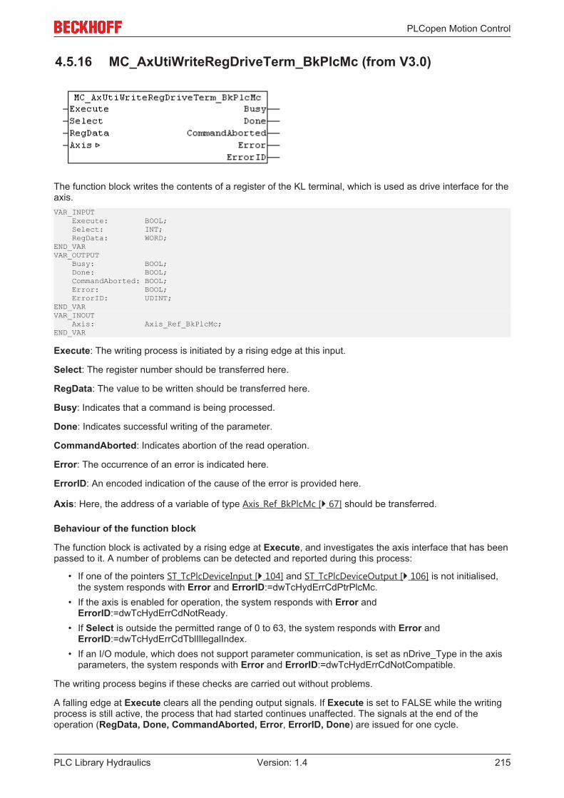
PLCopen Motion Control
PLC Library Hydraulics 215Version: 1.4
4.5.16 MC_AxUtiWriteRegDriveTerm_BkPlcMc (from V3.0)
The function block writes the contents of a register of the KL terminal, which is used as drive interface for theaxis.VAR_INPUT Execute: BOOL; Select: INT; RegData: WORD;END_VARVAR_OUTPUT Busy: BOOL; Done: BOOL; CommandAborted: BOOL; Error: BOOL; ErrorID: UDINT;END_VARVAR_INOUT Axis: Axis_Ref_BkPlcMc;END_VAR
Execute: The writing process is initiated by a rising edge at this input.
Select: The register number should be transferred here.
RegData: The value to be written should be transferred here.
Busy: Indicates that a command is being processed.
Done: Indicates successful writing of the parameter.
CommandAborted: Indicates abortion of the read operation.
Error: The occurrence of an error is indicated here.
ErrorID: An encoded indication of the cause of the error is provided here.
Axis: Here, the address of a variable of type Axis_Ref_BkPlcMc [} 67] should be transferred.
Behaviour of the function block
The function block is activated by a rising edge at Execute, and investigates the axis interface that has beenpassed to it. A number of problems can be detected and reported during this process:
• If one of the pointers ST_TcPlcDeviceInput [} 104] and ST_TcPlcDeviceOutput [} 106] is not initialised,the system responds with Error and ErrorID:=dwTcHydErrCdPtrPlcMc.
• If the axis is enabled for operation, the system responds with Error andErrorID:=dwTcHydErrCdNotReady.
• If Select is outside the permitted range of 0 to 63, the system responds with Error andErrorID:=dwTcHydErrCdTblIllegalIndex.
• If an I/O module, which does not support parameter communication, is set as nDrive_Type in the axisparameters, the system responds with Error and ErrorID:=dwTcHydErrCdNotCompatible.
The writing process begins if these checks are carried out without problems.
A falling edge at Execute clears all the pending output signals. If Execute is set to FALSE while the writingprocess is still active, the process that had started continues unaffected. The signals at the end of theoperation (RegData, Done, CommandAborted, Error, ErrorID, Done) are issued for one cycle.

PLCopen Motion Control
PLC Library Hydraulics216 Version: 1.4
NOTE! The drive types iTcMc_DriveKL2521, iTcMc_DriveKL4032, iTcMc_DriveKL2531 andiTcMc_DriveKL2541 support the parameter communication.
4.5.17 MC_AxUtiWriteRegEncTerm_BkPlcMc (from V3.0)
The function block writes the contents of a register of the KL terminal, which is used as encoder interface forthe axis.VAR_INPUT Execute: BOOL; Select: INT; RegData: WORD;END_VARVAR_OUTPUT Busy: BOOL; Done: BOOL; CommandAborted: BOOL; Error: BOOL; ErrorID: UDINT;END_VARVAR_INOUT Axis: Axis_Ref_BkPlcMc;END_VAR
Execute: The writing process is initiated by a rising edge at this input.
Select: The register number should be transferred here.
RegData: The value to be written should be transferred here.
Busy: Indicates that a command is being processed.
Done: Indicates successful writing of the parameter.
CommandAborted: Indicates abortion of the read operation.
Error: The occurrence of an error is indicated here.
ErrorID: An encoded indication of the cause of the error is provided here.
Axis: Here, the address of a variable of type Axis_Ref_BkPlcMc [} 67] should be transferred.
Behaviour of the function block
The function block is activated by a rising edge at Execute, and investigates the axis interface that has beenpassed to it. A number of problems can be detected and reported during this process:
• If one of the pointers ST_TcPlcDeviceInput [} 104] and ST_TcPlcDeviceOutput [} 106] is not initialised,the system responds with Error and ErrorID:=dwTcHydErrCdPtrPlcMc.
• If the axis is enabled for operation, the system responds with Error andErrorID:=dwTcHydErrCdNotReady.
• If Select is outside the permitted range of 0 to 63, the system responds with Error andErrorID:=dwTcHydErrCdTblIllegalIndex.
• If an I/O module, which does not support parameter communication, is set as nEncoder_Type in theaxis parameters, the system responds with Error and ErrorID:=dwTcHydErrCdNotCompatible.
The writing process begins if these checks are carried out without problems.

PLCopen Motion Control
PLC Library Hydraulics 217Version: 1.4
A falling edge at Execute clears all the pending output signals. If Execute is set to FALSE while the writingprocess is still active, the process that had started continues unaffected. The signals at the end of theoperation (RegData, Done, CommandAborted, Error, ErrorID, Done) are issued for one cycle.
NOTE! The drive types iTcMc_EncoderKL3002, iTcMc_EncoderKL3042, iTcMc_EncoderKL3062,iTcMc_EncoderKL3162, iTcMc_EncoderKL5101, iTcMc_EncoderKL5111, iTcMc_EncoderKL2521,iTcMc_EncoderKL2531 und iTcMc_EncoderKL2541 support parameter communication.
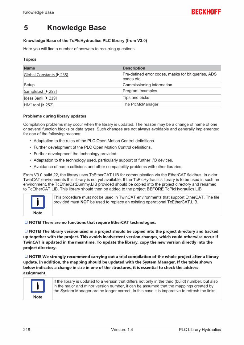
Knowledge Base
PLC Library Hydraulics218 Version: 1.4
5 Knowledge BaseKnowledge Base of the TcPlcHydraulics PLC library (from V3.0)
Here you will find a number of answers to recurring questions.
Topics
Name DescriptionGlobal Constants [} 235] Pre-defined error codes, masks for bit queries, ADS
codes etc.Setup Commissioning informationSampleList [} 255] Program examples
Ideas Bank [} 219] Tips and tricks
HMI tool [} 252] The PlcMcManager
Problems during library updates
Compilation problems may occur when the library is updated. The reason may be a change of name of oneor several function blocks or data types. Such changes are not always avoidable and generally implementedfor one of the following reasons:
• Adaptation to the rules of the PLC Open Motion Control definitions.• Further development of the PLC Open Motion Control definitions.• Further development the technology provided.• Adaptation to the technology used, particularly support of further I/O devices.• Avoidance of name collisions and other compatibility problems with other libraries.
From V3.0 build 22, the library uses TcEtherCAT.LIB for communication via the EtherCAT fieldbus. In olderTwinCAT environments this library is not yet available. If the TcPlcHydraulics library is to be used in such anenvironment, the TcEtherCatDummy.LIB provided should be copied into the project directory and renamedto TcEtherCAT.LIB. This library should then be added to the project BEFORE TcPlcHydraulics.LIB.
Note
This procedure must not be used in TwinCAT environments that support EtherCAT. The fileprovided must NOT be used to replace an existing operational TcEtherCAT.LIB.
NOTE! There are no functions that require EtherCAT technologies.
NOTE! The library version used in a project should be copied into the project directory and backedup together with the project. This avoids inadvertent version changes, which could otherwise occur ifTwinCAT is updated in the meantime. To update the library, copy the new version directly into theproject directory.
NOTE! We strongly recommend carrying out a trial compilation of the whole project after a libraryupdate. In addition, the mapping should be updated with the System Manager. If the table shownbelow indicates a change in size in one of the structures, it is essential to check the addressassignment.
Note
If the library is updated to a version that differs not only in the third (build) number, but alsoin the major and minor version number, it can be assumed that the mappings created bythe System Manager are no longer correct. In this case it is imperative to refresh the links.
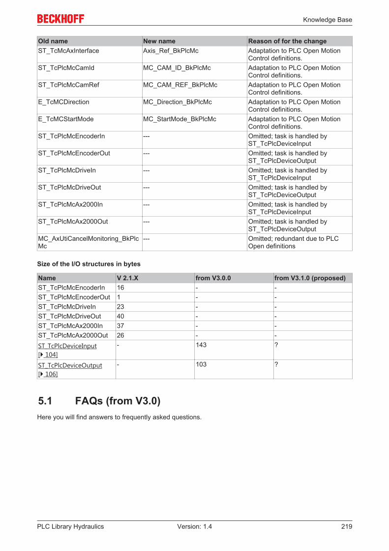
Knowledge Base
PLC Library Hydraulics 219Version: 1.4
Old name New name Reason of for the changeST_TcMcAxInterface Axis_Ref_BkPlcMc Adaptation to PLC Open Motion
Control definitions.ST_TcPlcMcCamId MC_CAM_ID_BkPlcMc Adaptation to PLC Open Motion
Control definitions.ST_TcPlcMcCamRef MC_CAM_REF_BkPlcMc Adaptation to PLC Open Motion
Control definitions.E_TcMCDirection MC_Direction_BkPlcMc Adaptation to PLC Open Motion
Control definitions.E_TcMCStartMode MC_StartMode_BkPlcMc Adaptation to PLC Open Motion
Control definitions.ST_TcPlcMcEncoderIn --- Omitted; task is handled by
ST_TcPlcDeviceInputST_TcPlcMcEncoderOut --- Omitted; task is handled by
ST_TcPlcDeviceOutputST_TcPlcMcDriveIn --- Omitted; task is handled by
ST_TcPlcDeviceInputST_TcPlcMcDriveOut --- Omitted; task is handled by
ST_TcPlcDeviceOutputST_TcPlcMcAx2000In --- Omitted; task is handled by
ST_TcPlcDeviceInputST_TcPlcMcAx2000Out --- Omitted; task is handled by
ST_TcPlcDeviceOutputMC_AxUtiCancelMonitoring_BkPlcMc
--- Omitted; redundant due to PLCOpen definitions
Size of the I/O structures in bytes
Name V 2.1.X from V3.0.0 from V3.1.0 (proposed)ST_TcPlcMcEncoderIn 16 - -ST_TcPlcMcEncoderOut 1 - -ST_TcPlcMcDriveIn 23 - -ST_TcPlcMcDriveOut 40 - -ST_TcPlcMcAx2000In 37 - -ST_TcPlcMcAx2000Out 26 - -ST_TcPlcDeviceInput[} 104]
- 143 ?
ST_TcPlcDeviceOutput[} 106]
- 103 ?
5.1 FAQs (from V3.0)Here you will find answers to frequently asked questions.

Knowledge Base
PLC Library Hydraulics220 Version: 1.4
Name DescriptionFAQ #1 [} 220] How do I integrate one or more axes into a PLC application?
FAQ #2 [} 221] What data has to be created in the PLC application for the axes?
FAQ #3 [} 221] How do I initialize the data and load the parameters for an axis when the PLC starts?
FAQ #4 [} 222] How is the actual position of the axes determined?
FAQ #5 [} 225] How is the control value for an axis created?
FAQ #6 [} 225] How is the control value for an axis prepared for output?
FAQ #7 [} 225] How is the control value output to an axis?
FAQ #8 [} 227] In what order should the function blocks of an axis be called?
FAQ #9 [} 227] How do I control a valve output stage (on-board or externally)?
FAQ #10 [} 227] How do I create a message buffer?
FAQ #11 [} 228] How do I abort monitoring of a function?
FAQ #12 [} 229] How do I monitor the communication with an I/O device?
FAQ #13 [} 229] How do I assign my own labels to customer-specific axis parameters?
FAQ #14 [} 229] How do I control a current valve?
FAQ #15 [} 229] Which axis variables should be logged with the Scope?
FAQ #16 [} 230] What is the purpose of the variable nDebugTag in Axis_Ref_BkPlcMc?
FAQ #17 [} 230] What has to be taken into account when Sercos drives are used?
FAQ #18 [} 231] How is a pressure or a force determined?
FAQ #19 [} 231] What has to be taken into account when AX5000 drives are used?
FAQ #20 [} 231] How do I prepare an axis for blending based on PLC Open?
FAQ #21 [} 233] How can I access registers of a terminal, to which an encoder or a valve of an axis isconnected?
FAQ #22 [} 233] What is the structure of an ASCII file for a linearization table?
FAQ #23 [} 234] How can PlcMcManager commands be blocked?Setup How is operation of the axis begun, and how is it optimized?
FAQ #1 How do I integrate one or more axes into a PLC application?
The procedure here differs fundamentally from an axis guided by the NC task, because in this caseeverything done by the NC task is performed by the PLC. Ready-made function blocks are, however,available in most areas, so that the additional programming effort is held within reasonable limits. Thefollowing particular points must be considered:
• Axis data in the PLC application (FAQ #2 [} 221])
• Initializing and loading the axis parameters when starting the PLC application (FAQ #3 [} 221])
• Acquisition of actual values (FAQ #4 [} 222])
• Generating control values (FAQ #5 [} 225])
• Processing control values in preparation for output (FAQ #6 [} 225])• Setting up the axes (Setup)• Commissioning of actual pressure determination with function blocks of type
MC_AxRtReadPressureSingle_BkPlcMc [} 158] or MC_AxRtReadPressureDiff_BkPlcMc [} 156].
• Organization of the procedure for movement (FAQ #7 [} 225])
NOTE! If only the usual blocks (encoder, generator, finish, drive) for the axis are to be called, ablock of type MC_AxStandardBody_BkPlcMc should be used for simplicity.

Knowledge Base
PLC Library Hydraulics 221Version: 1.4
FAQ #2 What data has to be created in the PLC application for the axes?
For each axis, one variables of each type Axis_Ref_BkPlcMc [} 67], ST_TcPlcDeviceInput [} 104] andST_TcPlcDeviceOutput [} 106] has to be created. The use of variable fields is highly recommended formultiple axes. Examples for one and five axes can be found in the sample programs https://infosys.beckhoff.com/content/1033/tcplcLibhydraulics30/Resources/zip/9007200854594443.zip and https://infosys.beckhoff.com/content/1033/tcplcLibhydraulics30/Resources/zip/9007200854596619.zip.
The procedure using MC_AxUtiStandardInit_BkPlcMc [} 182] function blocks shown in these examplesensures correct initialization on start-up of the PLC and initiates loading of the axis parameters from files.
NOTE! Further data are required for realizing message logging. See also FAQ #10 [} 227].
NOTE! Further data are required for assigning one's own IDs to customer-specific axis parametersin the PlcMcManager. See also FAQ #13 [} 229]
NOTE! Further data are required in order to utilize blending according to PLC Open. See also FAQ#20 [} 231].
FAQ #3 How do I initialize the data for an axis?
A number of initializations must be carried out when the PLC applications starts. This is best done in threestages, which are provided by an MC_AxUtiStandardInit_BkPlcMc [} 182] function block and should only berealized directly by the application in special cases. They are described here only for the sake ofcompleteness.
1. A number of pointers must be correctly set up to link the components of the axes together. This taskshould be solved with a function block of type MC_AxUtiStandardInit_BkPlcMc [} 182], which detects ashift or change in size in the memory or the change of a type code during a subsequent online changeand then ensures that the pointers are reinitialised and the parameters are reloaded.
2. The parameters for the axis must be appropriately set. Although it would be technically possible for theapplication to do have these assignments hard-coded, this is not usually helpful. It is preferable tosave the settings in files, which are loaded on system startup under control of the application throughthe MC_AxUtiStandardInit_BkPlcMc [} 182] function block. Notes on setting up an axis can be foundunder Setup.
3. The task cycle time should be applied in the axis parameters. This should be done at the end of theparameter loading procedure, in order to set this value correctly, in view of the fact that it is importantfor the function of many function blocks. An MC_AxUtiStandardInit_BkPlcMc [} 182] function blockdeals with this task automatically.
NOTE! If a function block of type MC_AxAdsCommServer_BkPlcMc is used in the application, thefunction block must be called in the same task that carries out the pointer assignments. If this is notpossible, or for some reason difficult, then calling the function block must be prevented while theassignments are being carried out. The result, otherwise, can be that the PLC application crashes as aresult of serious runtime errors (Page Fault Exception).
NOTE! All activities listed here should through be realized and coordinated by anMC_AxUtiStandardInit_BkPlcMc function block. If the nInitState variable in Axis_Ref_BkPlcMc of theaxis adopts either the value 2 or -2, then the initialization has been successful or has ended with anerror. If the initialization is successful, MC_AxUtiStandardInit_BkPlcMc.Ready and bParamsEnable inAxis_Ref_BkPlcMc are TRUE, otherwise this variable remains FALSE.
NOTE! The sample programs provided specify the name of the axis and the name (included thepath) of the corresponding parameter file. It is essential that these specifications are modified tomatch the particular application.

Knowledge Base
PLC Library Hydraulics222 Version: 1.4
FAQ #4: How is the actual position of the axes determined?
A range of signal transducers may be considered for use as position sensors, operating according to avariety of physical principles to generate a position-dependent electrical magnitude. This magnitudedetermines the type of I/O components that must be used. The variables of types ST_TcPlcDeviceInput[} 104] and ST_TcPlcDeviceOutput [} 106] must be created for each axis, and contain elements that are to belinked to the actual value, counter, latch, control and status variables associated with the I/O hardware.
Here are a few examples:

Knowledge Base
PLC Library Hydraulics 223Version: 1.4
I/O component Signal Encoder TypeAX2000 B110 with absoluteencoder
EtherCAT iTcMc_EncoderAx2000_B110A[} 136]
AX2000 B110 with resolver EtherCAT iTcMc_EncoderAx2000_B110R[} 126]
AX2000 B200 with resolver EtherCAT iTcMc_EncoderAx2000_B200R[} 126]
AX2000 B750 with absoluteencoder
EtherCAT iTcMc_EncoderAx2000_B750A[} 139]
AX2000 B900 with resolver EtherCAT iTcMc_EncoderAx2000_B900R[} 126]
AX5000 B110 with multi-turnabsolute encoder
EtherCAT iTcMc_EncoderAX5000_B110A[} 139]
EtherCAT servo controllers withCoE DS402 support and multi-turn encoder
EtherCAT iTcMc_EncoderCoE_DS402A [} 141]
EtherCAT servo controllers withCoE DS402 support and resolveror single-turn encoder
EtherCAT iTcMc_EncoderCoE_DS402SR[} 141]
EL3102 -10V .. 10V iTcMc_EncoderEL3102 [} 144]EL3142 0mA .. 20mA iTcMc_EncoderEL3142 [} 144]EL3162 0 .. 10V iTcMc_EncoderEL3162 [} 144]EL3255 Potentiometric displacement
transduceriTcMc_EncoderEL3162 [} 144]
EL5001 SSI iTcMc_EncoderEL5001 [} 145]EL5101 A/B increments, RS422="TTL" iTcMc_EncoderEL5101 [} 146]EL7041 A/B increments, RS422="TTL" iTcMc_EncoderEL7041 [} 147]EtherCAT encoder withCoE_DS406 profile
EtherCAT iTcMc_EncoderCoE_DS406 [} 142]
IE5009 SSI iTcMc_EncoderIx5009 [} 147]IP5009 SSI iTcMc_EncoderIx5009 [} 147]KL10xx 2 bit, A/B increments iTcMc_EncoderDigIncrement
[} 144]KL11xx 2 bit, A/B increments iTcMc_EncoderDigIncrement
[} 144]KL12xx 2 bit, A/B increments iTcMc_EncoderDigIncrement
[} 144]KL13xx 2 bit, A/B increments iTcMc_EncoderDigIncrement
[} 144]KL14xx 2 bit, A/B increments iTcMc_EncoderDigIncrement
[} 144]KL17xx 2 bit, A/B increments iTcMc_EncoderDigIncrement
[} 144]KL10xx 4 bit, position cams iTcMc_EncoderDigCam [} 144]KL11xx 4 bit, position cams iTcMc_EncoderDigCam [} 144]KL12xx 4 bit, position cams iTcMc_EncoderDigCam [} 144]KL13xx 4 bit, position cams iTcMc_EncoderDigCam [} 144]KL14xx 4 bit, position cams iTcMc_EncoderDigCam [} 144]KL17xx 4 bit, position cams iTcMc_EncoderDigCam [} 144]
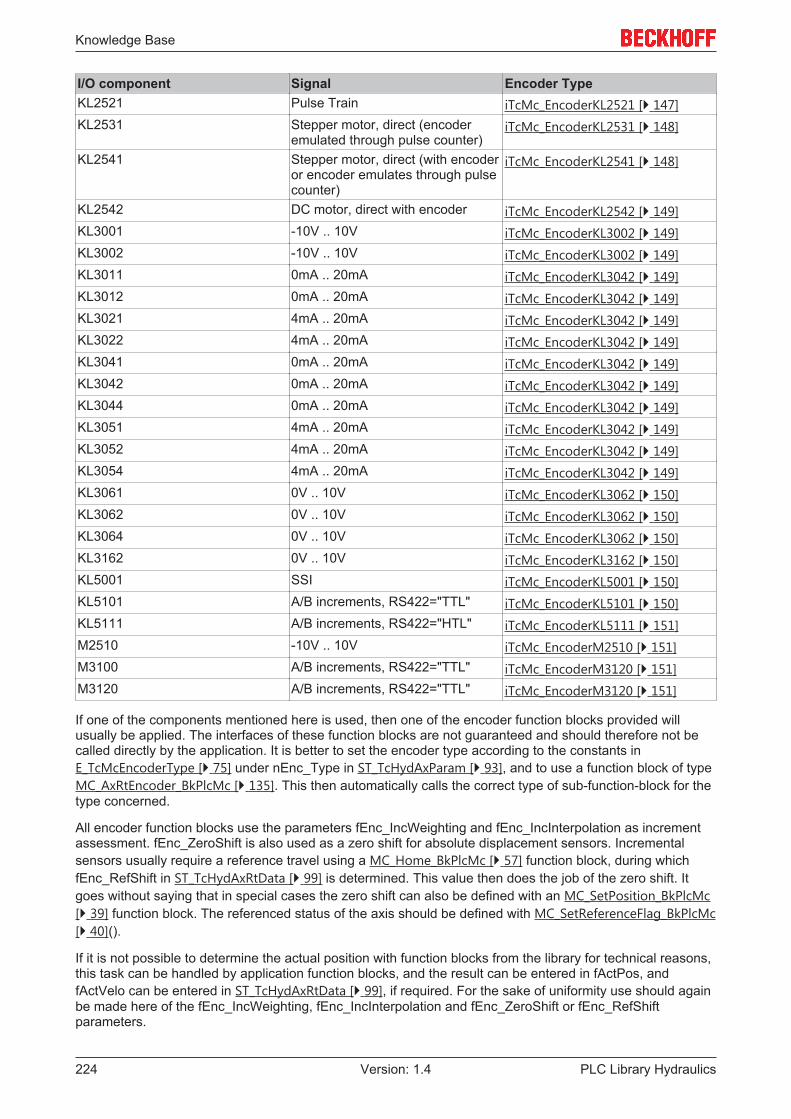
Knowledge Base
PLC Library Hydraulics224 Version: 1.4
I/O component Signal Encoder TypeKL2521 Pulse Train iTcMc_EncoderKL2521 [} 147]KL2531 Stepper motor, direct (encoder
emulated through pulse counter)iTcMc_EncoderKL2531 [} 148]
KL2541 Stepper motor, direct (with encoderor encoder emulates through pulsecounter)
iTcMc_EncoderKL2541 [} 148]
KL2542 DC motor, direct with encoder iTcMc_EncoderKL2542 [} 149]KL3001 -10V .. 10V iTcMc_EncoderKL3002 [} 149]KL3002 -10V .. 10V iTcMc_EncoderKL3002 [} 149]KL3011 0mA .. 20mA iTcMc_EncoderKL3042 [} 149]KL3012 0mA .. 20mA iTcMc_EncoderKL3042 [} 149]KL3021 4mA .. 20mA iTcMc_EncoderKL3042 [} 149]KL3022 4mA .. 20mA iTcMc_EncoderKL3042 [} 149]KL3041 0mA .. 20mA iTcMc_EncoderKL3042 [} 149]KL3042 0mA .. 20mA iTcMc_EncoderKL3042 [} 149]KL3044 0mA .. 20mA iTcMc_EncoderKL3042 [} 149]KL3051 4mA .. 20mA iTcMc_EncoderKL3042 [} 149]KL3052 4mA .. 20mA iTcMc_EncoderKL3042 [} 149]KL3054 4mA .. 20mA iTcMc_EncoderKL3042 [} 149]KL3061 0V .. 10V iTcMc_EncoderKL3062 [} 150]KL3062 0V .. 10V iTcMc_EncoderKL3062 [} 150]KL3064 0V .. 10V iTcMc_EncoderKL3062 [} 150]KL3162 0V .. 10V iTcMc_EncoderKL3162 [} 150]KL5001 SSI iTcMc_EncoderKL5001 [} 150]KL5101 A/B increments, RS422="TTL" iTcMc_EncoderKL5101 [} 150]KL5111 A/B increments, RS422="HTL" iTcMc_EncoderKL5111 [} 151]M2510 -10V .. 10V iTcMc_EncoderM2510 [} 151]M3100 A/B increments, RS422="TTL" iTcMc_EncoderM3120 [} 151]M3120 A/B increments, RS422="TTL" iTcMc_EncoderM3120 [} 151]
If one of the components mentioned here is used, then one of the encoder function blocks provided willusually be applied. The interfaces of these function blocks are not guaranteed and should therefore not becalled directly by the application. It is better to set the encoder type according to the constants inE_TcMcEncoderType [} 75] under nEnc_Type in ST_TcHydAxParam [} 93], and to use a function block of typeMC_AxRtEncoder_BkPlcMc [} 135]. This then automatically calls the correct type of sub-function-block for thetype concerned.
All encoder function blocks use the parameters fEnc_IncWeighting and fEnc_IncInterpolation as incrementassessment. fEnc_ZeroShift is also used as a zero shift for absolute displacement sensors. Incrementalsensors usually require a reference travel using a MC_Home_BkPlcMc [} 57] function block, during whichfEnc_RefShift in ST_TcHydAxRtData [} 99] is determined. This value then does the job of the zero shift. Itgoes without saying that in special cases the zero shift can also be defined with an MC_SetPosition_BkPlcMc[} 39] function block. The referenced status of the axis should be defined with MC_SetReferenceFlag_BkPlcMc[} 40]().
If it is not possible to determine the actual position with function blocks from the library for technical reasons,this task can be handled by application function blocks, and the result can be entered in fActPos, andfActVelo can be entered in ST_TcHydAxRtData [} 99], if required. For the sake of uniformity use should againbe made here of the fEnc_IncWeighting, fEnc_IncInterpolation and fEnc_ZeroShift or fEnc_RefShiftparameters.

Knowledge Base
PLC Library Hydraulics 225Version: 1.4
NOTE! If only the usual function blocks (encoder, generator, finish, drive) for the axis are to becalled, a function block of type MC_AxStandardBody_BkPlcMc should be used for simplicity.
NOTE! Commissioning of an actual pressure determination with function blocks of typeMC_AxRtReadPressureSingle_BkPlcMc or MC_AxRtReadPressureDiff_BkPlcMc is described in thedocumentation for the function block.
FAQ #5: How is the control value for an axis created?
In each cycle, the PLC application must call a function block of type MC_AxRuntime_BkPlcMc [} 167], oralternatively a suitable controller function block (e.g. a pressure regulator) for each axis. The parameternProfileType in ST_TcHydAxParam [} 93] specifies the procedure that is to be used to generate the controlvalue. Velocity control values are calculated here according to the type, and depending on other parametersassociated with the axis and on the movement data. These control values are, however, normalized to theabstract numerical range ±1.0, and have not yet been prepared for immediate output to I/O hardware.
NOTE! If only the usual function blocks (encoder, generator, finish, drive) for the axis are to becalled, a function block of type MC_AxStandardBody_BkPlcMc [} 181]should be used for simplicity.
FAQ #6: How is the control value for an axis prepared for output?
After calling the MC_AxRuntime_BkPlcMc [} 167] function block, a function block of typeMC_AxRtFinish_BkPlcMc [} 175] must be called for each axis. This function block assembles a number ofvelocity components (control value, controller output, offset compensation, overlap compensation), and alsotakes into account in the bends in the feed forward characteristic curve.
Numerical adjustment is usually necessary prior to output to an I/O module. An MC_AxRtDrive_BkPlcMc[} 125] function block is to be called for each axis for this purpose. The value of nDrive_Type inST_TcHydAxParam [} 93] selects the hardware-specific sub-function-block to be used.
The variables of types ST_TcPlcDeviceInput [} 104] and ST_TcPlcDeviceOutput [} 106] must be created foreach axis, and contain elements that are to be linked to the set value and control variables of the I/Ohardware.
NOTE! If only the usual blocks (encoder, generator, finish, drive) for the axis are to be called, ablock of type MC_AxStandardBody_BkPlcMc [} 181] should be used for simplicity.
FAQ #7: How is the control value output to an axis?
A range of devices and equipment might be functioning as actuators, applying a variety of physical principlesto create a variable velocity that depends on an electrical magnitude. This magnitude determines the type ofI/O components that must be used. The variables of types ST_TcPlcDeviceInput [} 104] andST_TcPlcDeviceOutput [} 106] must be created for each axis, and contain elements that are to be linked tothe variables of the I/O hardware.
Here are a few examples:
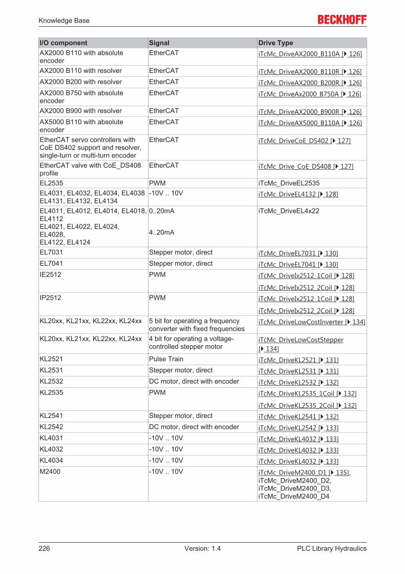
Knowledge Base
PLC Library Hydraulics226 Version: 1.4
I/O component Signal Drive TypeAX2000 B110 with absoluteencoder
EtherCAT iTcMc_DriveAX2000_B110A [} 126]
AX2000 B110 with resolver EtherCAT iTcMc_DriveAX2000_B110R [} 126]AX2000 B200 with resolver EtherCAT iTcMc_DriveAX2000_B200R [} 126]AX2000 B750 with absoluteencoder
EtherCAT iTcMc_DriveAx2000_B750A [} 126]
AX2000 B900 with resolver EtherCAT iTcMc_DriveAX2000_B900R [} 126]AX5000 B110 with absoluteencoder
EtherCAT iTcMc_DriveAX5000_B110A [} 126]
EtherCAT servo controllers withCoE DS402 support and resolver,single-turn or multi-turn encoder
EtherCAT iTcMc_DriveCoE_DS402 [} 127]
EtherCAT valve with CoE_DS408profile
EtherCAT iTcMc_Drive_CoE_DS408 [} 127]
EL2535 PWM iTcMc_DriveEL2535EL4031, EL4032, EL4034, EL4038 EL4131, EL4132, EL4134
-10V .. 10V iTcMc_DriveEL4132 [} 128]
EL4011, EL4012, EL4014, EL4018, EL4112EL4021, EL4022, EL4024,EL4028,EL4122, EL4124
0..20mA
4..20mA
iTcMc_DriveEL4x22
EL7031 Stepper motor, direct iTcMc_DriveEL7031 [} 130]EL7041 Stepper motor, direct iTcMc_DriveEL7041 [} 130]IE2512 PWM iTcMc_DriveIx2512_1Coil [} 128]
iTcMc_DriveIx2512_2Coil [} 128]IP2512 PWM iTcMc_DriveIx2512_1Coil [} 128]
iTcMc_DriveIx2512_2Coil [} 128]KL20xx, KL21xx, KL22xx, KL24xx 5 bit for operating a frequency
converter with fixed frequenciesiTcMc_DriveLowCostInverter [} 134]
KL20xx, KL21xx, KL22xx, KL24xx 4 bit for operating a voltage-controlled stepper motor
iTcMc_DriveLowCostStepper[} 134]
KL2521 Pulse Train iTcMc_DriveKL2521 [} 131]KL2531 Stepper motor, direct iTcMc_DriveKL2531 [} 131]KL2532 DC motor, direct with encoder iTcMc_DriveKL2532 [} 132]KL2535 PWM iTcMc_DriveKL2535_1Coil [} 132]
iTcMc_DriveKL2535_2Coil [} 132]KL2541 Stepper motor, direct iTcMc_DriveKL2541 [} 132]KL2542 DC motor, direct with encoder iTcMc_DriveKL2542 [} 133]KL4031 -10V .. 10V iTcMc_DriveKL4032 [} 133]KL4032 -10V .. 10V iTcMc_DriveKL4032 [} 133]KL4034 -10V .. 10V iTcMc_DriveKL4032 [} 133]M2400 -10V .. 10V iTcMc_DriveM2400_D1 [} 135],
iTcMc_DriveM2400_D2,iTcMc_DriveM2400_D3,iTcMc_DriveM2400_D4

Knowledge Base
PLC Library Hydraulics 227Version: 1.4
If one of the components mentioned here is used, then one of the drive function blocks provided will usuallybe used. These interfaces of these function blocks are not guaranteed and should therefore not be calleddirectly by the application. It is better to set the drive type according to the constants in E_TcMcDriveType[} 72] under nDrive_Type in ST_TcHydAxParam [} 93], and to use a function block of typeMC_AxRtDrive_BkPlcMc [} 125].
NOTE! If only the usual function blocks (encoder, generator, finish, drive) for the axis are to becalled, a function block of type MC_AxStandardBody_BkPlcMc [} 181]should be used for simplicity.
FAQ #8: In what order should the function blocks of an axis be called?
1. Obligatory: all function blocks, which detect the actual status of the axis. These include function blocksof types MC_AxRtEncoder_BkPlcMc [} 135], MC_AxRtReadPressureDiff_BkPlcMc [} 156] orMC_AxRtReadPressureSingle_BkPlcMc [} 158].
2. Usual: function blocks or commands, which update the enable signals of the axis. This is usually afunction block of type MC_Power_BkPlcMc [} 26]. For axes with an incremental encoder, which is refer-enced using a cam, a function call MC_AxRtSetReferencingCamSignal_BkPlcMc is used in addition.
3. Optional: Function blocks, which derive a decision or trigger a command based on an actual axis sta-tus, an I/O signal or an application signal. For example, an axis start can be triggered in response tothe signal of a proximity limit switch, or an axis movement can be stopped before the target position isreached, depending on the pressure increase.
4. Obligatory: Control value generators such as function blocks of type MC_AxRuntime_BkPlcMc [} 167].5. Optional: Various controllers can be called at this point, as required. This can be a function block of
type MC_AxCtrlSlowDownOnPressure_BkPlcMc [} 119] or similar.6. Obligatory: An adaptation function block of type MC_AxRtFinish_BkPlcMc [} 175].7. Optional: If required, a function block for the automatic commissioning can be called at this point.8. Obligatory: An output function block of type MC_AxRtDrive_BkPlcMc [} 125].
Instead of the library function blocks, application function blocks can be used. However, one should checkcarefully whether this is necessary, in which case compatibility with the library must be ensured. In someapplications this may become necessary, in order to adapt a non-standard sensor or actuator, or to solve aspecial control task.
FAQ #9: How do I control a valve output stage (on-board or externally)?
The ST_TcPlcDeviceOutput [} 106] structure is intended for the bPowerOn and bEnable signals and forcontrolling the output stage supply and activation. Both signals are set by function blocks of typeMC_Power_BkPlcMc [} 26], if the input Enable is set. At the same time this function block sets the softwarecontroller enable in ST_TcHydAxRtData [} 99].nDeCtrlDWord [} 236].
The ST_TcPlcDeviceInput [} 104] structure is intended for the signals bPowerOk, bEnAck and bReady forthe output stage supply control, feedback from the output stage activation and the status signal. Thedifferences in the signals provided by different manufacturer can be very significant. Currently, only thebPowerOk signal is used for specifying the Status output of the MC_Power_BkPlcMc [} 26] function block. Ifno suitable signal is available, or if no monitoring is to be realised, ST_TcHydAxParam[} 93].bDrive_DefaultPowerOk should be set.
FAQ #10: How do I create a message buffer?
Direct output of messages from the function blocks would result in runtime variations that would be difficult tocalculate. For this reason, the messages are stored in a buffer and output in the Windows Event Viewer oneafter another, if required.
In order to be able to use a message buffer, a variable of type ST_TcPlcMcLogBuffer [} 107] must be created.This buffer is used to hold the messages from all axes. It is important that only one such variable is createdin the project, irrespective of the number of axes. The address of this buffer should be transferred to theMC_AxUtiStandardInit_BkPlcMc [} 182] function blocks of all axes, together with the addresses of the other
Knowledge Base
PLC Library Hydraulics228 Version: 1.4
individual axis components. This function blocks are usually called in the initialization part of the project. Thisaddress is stored in the element pStAxLogBuffer in the structure Axis_Ref_BkPlcMc [} 67] and by the functionblock.
nLogLevel in Axis_Ref_BkPlcMc [} 67] is used to specify the significance level threshold for storing messagesin the buffer. The values [} 244] to be used are defined in the global variables of the library. Note that thissetting is required for each axis.
The library function blocks detect the preparations mentioned above and will commence issuing messages.However, if the message output is enabled, the buffer would fill up quickly and not accept further messages.There are two ways to avoid this.
FAQ #10.1: Passing on messages to the Windows Event Viewer
In order to transfer messages from the LogBuffer of the library to the Windows Event Viewer, a functionblock of type MC_AxRtLoggerSpool_BkPlcMc [} 187] should be called cyclically. Witch each call a message isremoved from the LogBuffer.
NOTE! Computers running Windows CE are also capable of amending an Event Viewer for themessages created by TwinCAT. To this end this service is emulated by the TwinCAT system service.However, usually only a flash disk will be available. In order to avoid overloading the relatively smallmessage capacity of the Event Viewer, only errors should be logged.
FAQ #10.2: Deleting the oldest messages
In order to ensure a minimum number of messages that can be handled, a function block of typeMC_AxRtLoggerDespool_BkPlcMc [} 186] should be called cyclically. With each call, this function blockremoves the oldest message from the LogBuffer, until a transferred number of free messages is available.The deleted messages are lost.
FAQ #10.3: Generating logger entries through the application
An application can output a message either axis-related or non-axis-related. The function blocksMC_AxRtLogAxisEntry_BkPlcMc [} 184] and MC_AxRtLogEntry_BkPlcMc [} 185] are available for this purpose.
FAQ #11: How do I abort monitoring of a function?
Some library function blocks start an activity, for which cyclic calling is no longer essential. However, thesefunction blocks are also structured according to the rules of the PLCopen Motion Control guidelines in such away that they fully monitor the activity and present it at their outputs. This is indicated by the output Busy,which most function blocks provide.
Omitting the cyclic call of a function block that is in this monitoring state would usually result in significantproblems. The next function start with the respective function block would have problems with evaluating theedges at its inputs, or it would detect that meanwhile the axis has executed another function and indicated aproblem that doesn't exist (CommandAborted).
In older versions of the library a function block of type MC_AxUtiCancelMonitoring_BkPlcMc() was provided,which for a few motion functions aborted the monitoring by the function block initiating the function. Thisfunction block is no longer required, in view of the fact that in the meantime the PLC Open rules have beenimplemented more fully.
To instruct a function block to terminate monitoring its function, in most cases it is sufficient to call it once orseveral times with Execute:=FALSE. This applies in particular to MC_MoveAbsolute_BkPlcMc [} 60](),MC_MoveRelative_BkPlcMc [} 63]() and MC_MoveVelocity_BkPlcMc [} 64]().
Subsequently, a new functionality can be started in same or a later cycle with the same function block or aninstance of the same or another type. This procedure can be repeated as required.
NOTE! Complex functions consisting of several sub-actions such as MC_Home_BkPlcMc() requirethe function block to be called continuously, since the function block organizes the required processesitself. MC_Home_BkPlcMc()) [} 57]

Knowledge Base
PLC Library Hydraulics 229Version: 1.4
FAQ #12: How do I monitor the communication with an I/O device?
ST_TcPlcDeviceInput [} 104] and ST_TcPlcDeviceOutput [} 106] variables provide an element with the nameuiBoxState. If the Bus Couplers or the interface cards of the power units used offer a corresponding variableand the variable assumes the value 0 with undisturbed communication in the fieldbus used, a link should becreated. This is possible, for example, with Beckhoff Lightbus and Real-time Ethernet. If anMC_Power_BkPlcMc [} 26] function block is used for the axis, the function block monitors the uiBoxState andreports problems with the communication. In such a case the axis is put in an error state.
EtherCAT offers enhanced options.
FAQ #13: How do I assign my own labels to customer-specific axis parameters?
The Axis_Ref_BkPlcMc [} 67] structure uses the pAuxLabels pointer to support the application of an array oftexts, which are displayed by the PlcMcManager. These texts can be loaded by theMC_AxUtiStandardInit_BkPlcMc [} 182] function block when the application is started from a file. To this endthis function block must be provided with the address of an ST_TcMcAuxDataLabels [} 103] variable and asuitable file.
It goes without saying that it is also possible to define the elements of the ST_TcMcAuxDataLabels [} 103]variable through direct assignment from the application. In this case, the file is not required.
NOTE! A number of controller function blocks of the library define the arrays texts automatically.
FAQ #14: How do I control a current valve?
In contrast to a 4/2 or 3/2 directional proportional valve or a servo valve, a current valve is controlled with a0..10 V signal (if a valve output stage is present) or actuated with a load-independent current of 0...INominal. Inthis control, only the magnitude of the velocity is transferred. The direction is transferred not with the sign,but by other means. This usually requires digital signals, which are used for controlling switching valves. TheST_TcPlcDeviceOutput [} 106] structure provides elements such as bBrakeOff, bMovePos and bMoveNegfor this purpose. For generating an absolute control value, bDrive_AbsoluteOutput should be set in the axisparameters.
NOTE! This also enables the use of conventional frequency converters with asynchronous motor,encoder and brake, if the converter provides an analog input.
FAQ #15: Which axis variables should be logged with the Scope?
The following signal composition is recommended:
• Always: actual axis position: Axis_Ref_BkPlcMc.ST_TcHydAxRtData [} 99].fActPos: in actual valueunits, as specified by the encoder scaling.
• Only for gear or synchronization coupling, cam plate: set axis position:Axis_Ref_BkPlcMc.ST_TcHydAxRtData.fSetPos: in actual value units, as specified by the encoderscaling.
• Particularly during commissioning: actual velocity value:Axis_Ref_BkPlcMc.ST_TcHydAxRtData.fActVelo: velocity in physical representation.
• Particularly during commissioning: residual distance or target position:Axis_Ref_BkPlcMc.ST_TcHydAxRtData.fDistanceToTarget orAxis_Ref_BkPlcMc.ST_TcHydAxRtData.fTargetPos: in actual value units, as specified by the encoderscaling.
• Only if pressure/force logging is active: various actual pressure and force values: inAxis_Ref_BkPlcMc.ST_TcHydAxRtData: as required fActPressure fActPressureA fActPressureBfActForce fValvePressure fSupplyPressure: pressures and forces, unit is defined throughparameterization of the logging function blocks.
• Particularly during commissioning: velocity control value:Axis_Ref_BkPlcMc.ST_TcHydAxRtData.fActVelo: velocity in physical representation.
• Particularly during commissioning: controller output:Axis_Ref_BkPlcMc.ST_TcHydAxRtData.fLagCtrlOutput: velocity in physical representation.
Knowledge Base
PLC Library Hydraulics230 Version: 1.4
NOTE! The signal selection in ScopeView is simplified if the Axis_Ref_BkPlcMc variables contain aname that begins with aaa_. This approach is used in the sample programs and ensures that thevariables can be found quickly in the symbol list.
NOTE! In the signal composition of ScopeView, channels can be temporarily disabled. In this way itis possible to maintain a comprehensive configuration but limit logging to data that are currently ofinterest.
FAQ #16: What is the purpose of the variable nDebugTag in Axis_Ref_BkPlcMc?
This variable is used by nearly all library function blocks to store a unique ID for the duration of theirexecution. To this end the content that was found is stored in a local variable of the function block andrestored immediately before the function block is exited.
Should the program crash, or if there is a suspicion that there was a problem in a library function block, thenDebugTag variables of all axes should be checked. If a value <> 0 is present, the function block wasaffected by the crash, and the reason should be investigated. The numeric values used are listed in thelibrary under "Global constants". In addition, the contents of ST_TcHydAxRtData [} 99].sTopBlockNameshould be determined. Usually, the name of the function block called directly by the application can be foundhere.
FAQ #17: What has to be taken into account when Sercos drives are used?
If Sercos drives (from V3.0.26) are used, the following rules must be followed:
• The Sercos master interface (e.g. FC7501 etc.) must be allocated the name "SercosMaster" in theSystem Manager. Otherwise neither control of the Sercos phase nor parameter and diagnosticscommunication is possible.
• Only a Sercos segment with the library can be used.• In the System Manager, the drive devices at the Sercos Segment should be allocated the name under
which they are known to the library by calling the MC_AxUtiStandardInit_BkPlcMc() function block.Otherwise neither control of the Sercos phase nor parameter and diagnostics communication ispossible.
• The input variable SystemState [} 126] of the Sercos master interface should be linked for each drivedevice of the Sercos segment.
• If one or several drives at the Sercos segment are reset, the segment can interrupt the fieldbus. In thiscase, the Sercos master interface will undergo a corresponding phase change. Usually, the startup upto phase 4 will be automatic. Then:
◦ the axis addressed by the reset will be error-free, as long as there are no ongoing problems.◦ all other axes at the Sercos segment will be in error state (fieldbus failure, axis not ready for
operation). Once the triggering reset of the first axis has been processed, the other axes canusually be brought into an error-free state through a reset without a phase change.
This behavior is determined by characteristics of the Sercos fieldbus and cannot be influenced bythe library. It must be taken into account in the application in a suitable manner.
• Depending on certain parameter settings of the drive actuator, axis parameters are determinedautomatically or have to be specified manually:
◦ S-0-0076, bits 0 to 2 specify the weighting type of the position data. Supported features:◦ a) 0 0 1 translatory weighting:
S-0-0123 defines the rotation resolution (encoder-interpolation). The revolutional feed rate iscalculated from this number and the weighting (S-0-0077, S-0-0078).
◦ b) 0 1 0 rotary weighting: S-0-0079 defines the rotation resolution (encoder-interpolation). The revolutional feed rate hasto be set manually.
◦ S-0-0044, bits 0 to 2 specify the weighting type of the velocity data. Supported features:◦ a) 0 0 1 translatory weighting:
The velocity control value is converted to a velocity in encoder increments per time, based onthe revolutional feed rate and the rotation resolution. This information is offset against thevelocity resolution (S-0-0045, S-0-0046) and output.

Knowledge Base
PLC Library Hydraulics 231Version: 1.4
◦ b) 0 1 0 rotational weighting The velocity control value is converted to a speed based on the revolutional feed rate andoutput.
◦ S-0-0091 is converted with the method described above for velocity control values and usedas reference velocity. If the maximum speed exceeds the value determined in this way, it islimited accordingly.
FAQ #18: How is a pressure or a force determined?
To determine an actual pressure or an actual force, one or several function blocks of typesMC_AxRtReadPressureDiff_BkPlcMc [} 156], MC_AxRtReadForceDiff_BkPlcMc [} 152],MC_AxRtReadForceSingle_BkPlcMc [} 154] or MC_AxRtReadPressureSingle_BkPlcMc [} 158] have to be calledfor each axis. Details for the call sequence can be found under FAQ #8 [} 227].
The AD converter values to be transferred to the function blocks have to be linked with allocated variables ofthe application. Details regarding selection and parameterization can be found in the function blocksdescriptions.
FAQ #19: What has to be taken into account when AX5000 drives are used?
For AX5000 devices, a number of IDNs are read from the device, and a number of different parameters arecalculated automatically.
IDN Used for parameter44 Reference velocity, internally: scaling of the velocity
output45 Internal: scaling of the velocity output46 Internal: scaling of the velocity output76 Encoder interpolation79 Encoder interpolation91 Reference velocity
The following parameters are thus set automatically and cannot be influenced via the PlcMcManager:
Parameter influences which other parame-ters
Global: reference velocity Calculated from the maximumspeed of the device and therevolutional feed rate
Manuel velocities, max. appl.velocity
Encoder: inc. interpolation Read from IDN79 of the device Attention: the revolutional feedrate has to be entered as inc.evaluation
FAQ #20: How do I prepare an axis for blending based on PLC Open?
In Hydraulik.lib it is possible to command up to 12 buffered movements. For this purpose, a command bufferof type ST_TcPlcCmdCmdBuffer_BkPlcMc must be passed to the MC_AxUtiStandardInit_BkPlcMc [} 182]function block for updating the axis reference and a function block MC_AxRtCmdBufferExecute_BkPlcMcmust be called cyclically.
If Move function blocks such as MC_MoveAbsolute_BkPlcMc [} 60], MC_MoveRelative_BkPlcMc [} 63] orMC_MoveVelocity_BkPlcMc [} 64] are now activated, they enter their data in the command buffer.
In buffered mode make sure that the Move function blocks and the MC_AxRuntime_BkPlcMc [} 167] functionblock of the axis run in a PLC task.

Knowledge Base
PLC Library Hydraulics232 Version: 1.4
Transition between a slow and a fast section.

Knowledge Base
PLC Library Hydraulics 233Version: 1.4
Transition between a fast and a slow section.
FAQ #21: How can I access registers of a terminal, to which an encoder or a valve of an axis isconnected?
For register communication with terminals to which the encoder or the valve of an axis is connected, it isrecommended to use function blocks of types MC_AxUtiReadRegDriveTerm_BkPlcMc [} 207](),MC_AxUtiReadRegEncTerm_BkPlcMc [} 208](), MC_AxUtiWriteRegDriveTerm_BkPlcMc [} 215]() andMC_AxUtiWriteRegEncTerm_BkPlcMc [} 216]().
FAQ #22: What is the structure of an ASCII file for a linearization table?
The format of an ASCII file from a linearization table is specified as follows:
• One linearization point per row.• For each row first a velocity value, then an output value.• The velocity values are normalized to the reference velocity. They are therefore in the range -1,000 to
1,000 inclusive.• The output values are normalized to the full scale value. They therefore cover the range -1,000 to
1,000.

Knowledge Base
PLC Library Hydraulics234 Version: 1.4
• The first value in a row may be preceded by white space characters (space, tab).• Between the two values in row there must be at least one white space character (space, tab).• Between the two values of a row there may be further white space characters (space, tab).• Point and comma are permitted as decimal separator.• No non-digits are permitted between a negative sign and the first digit.• The first point specifies the negative end of the table.• The velocity value of all further points must be higher (i.e. less negative or more positive) than its
predecessor.• It makes sense if the output value of a point is higher (i.e. less negative or more positive) than its
predecessor, since otherwise there would be a negative slope in this section. This would result in achange of sign of the gain and therefore instability in an active control.
• The zero point (i.e. both coordinates of the point are 0.000) has to be specified.
Example: The following (idealized) table describes a cylinder, which in negative direction only reaches halfthe velocity of the positive direction due to asymmetric effective areas (due to single-sided piston rod). It isassumed that the cylinder is operated with a zero overlap valve with a bend in the characteristic curve at40%
Normalized velocity Normalized output-0.500 -1.000-0.430 -0.900-0.360 -0.800-0.290 -0.700-0.220 -0.600-0.150 -0.500-0.080 -0.400-0.060 -0.300-0.040 -0.200-0.020 -0.1000.000 0.0000.040 0.1000.080 0.2000.120 0.3000.160 0.4000.300 0.5000.440 0.6000.580 0.7000.720 0.8000.860 0.9001.000 1.000
FAQ #23: How can PlcMcManager commands be blocked?
In some situations the triggering of commands by the PlcMcManager can be problematic. This would be thecase if a certain sequence of actions has to be processed completely, for example. In order to preventinadvertent issuing of commands by the PlcMcManager in such cases, theMC_AxRtCommandsLocked_BkPlcMc [} 187] function can be used to enter a lock in the status double word ofthe axis. If this lock is active, any command sent by PlcMcManager sent is rejected with a write protectionerror.
NOTE! It is essential to remove the lock, once the action to be protected has been processed. Thisalso and in particular applies in the event of errors.
An example is available.
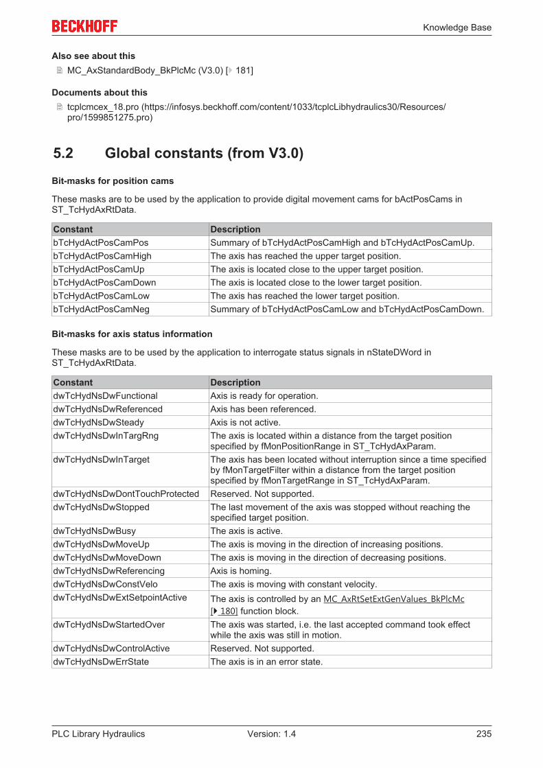
Knowledge Base
PLC Library Hydraulics 235Version: 1.4
Also see about this2 MC_AxStandardBody_BkPlcMc (V3.0) [} 181]
Documents about this2 tcplcmcex_18.pro (https://infosys.beckhoff.com/content/1033/tcplcLibhydraulics30/Resources/
pro/1599851275.pro)
5.2 Global constants (from V3.0)
Bit-masks for position cams
These masks are to be used by the application to provide digital movement cams for bActPosCams inST_TcHydAxRtData.
Constant DescriptionbTcHydActPosCamPos Summary of bTcHydActPosCamHigh and bTcHydActPosCamUp.bTcHydActPosCamHigh The axis has reached the upper target position.bTcHydActPosCamUp The axis is located close to the upper target position.bTcHydActPosCamDown The axis is located close to the lower target position.bTcHydActPosCamLow The axis has reached the lower target position.bTcHydActPosCamNeg Summary of bTcHydActPosCamLow and bTcHydActPosCamDown.
Bit-masks for axis status information
These masks are to be used by the application to interrogate status signals in nStateDWord inST_TcHydAxRtData.
Constant DescriptiondwTcHydNsDwFunctional Axis is ready for operation.dwTcHydNsDwReferenced Axis has been referenced.dwTcHydNsDwSteady Axis is not active.dwTcHydNsDwInTargRng The axis is located within a distance from the target position
specified by fMonPositionRange in ST_TcHydAxParam.dwTcHydNsDwInTarget The axis has been located without interruption since a time specified
by fMonTargetFilter within a distance from the target positionspecified by fMonTargetRange in ST_TcHydAxParam.
dwTcHydNsDwDontTouchProtected Reserved. Not supported.dwTcHydNsDwStopped The last movement of the axis was stopped without reaching the
specified target position.dwTcHydNsDwBusy The axis is active.dwTcHydNsDwMoveUp The axis is moving in the direction of increasing positions.dwTcHydNsDwMoveDown The axis is moving in the direction of decreasing positions.dwTcHydNsDwReferencing Axis is homing.dwTcHydNsDwConstVelo The axis is moving with constant velocity.dwTcHydNsDwExtSetpointActive The axis is controlled by an MC_AxRtSetExtGenValues_BkPlcMc
[} 180] function block.dwTcHydNsDwStartedOver The axis was started, i.e. the last accepted command took effect
while the axis was still in motion.dwTcHydNsDwControlActive Reserved. Not supported.dwTcHydNsDwErrState The axis is in an error state.

Knowledge Base
PLC Library Hydraulics236 Version: 1.4
Bit-masks for axis enable information
These masks are to be used by the application to provide enable signals in nDeCtrlDWord inST_TcHydAxRtData.
Constant DescriptiondwTcHydDcDwCtrlEnable Controller enable. This enable is a precondition for the output of
control value and controller outputs.dwTcHydDcDwFdPosEna Advance movement enable in positive direction. This enable is a
precondition for the output of control value and controller outputs inthe direction of increasing values of position.
dwTcHydDcDwCtrlPosEna Combination of dwTcHydDcDwCtrlEnable anddwTcHydDcDwFdPosEna.
dwTcHydDcDwFdNegEna Advance movement enable in negative direction. This enable is aprecondition for the output of control value and controller outputs inthe direction of decreasing values of position.
dwTcHydDcDwCtrlNegEna Combination of dwTcHydDcDwCtrlEnable anddwTcHydDcDwFdNegEna.
dwTcHydDcDwRefIndex Referencing cam.dwTcHydDcDwAcceptBlockedDrive Reserved. Not supported.dwTcHydDcDwBlockedDriveDetected Reserved. Not fully supported. Note: This signal suppresses any
active velocity controller.
Error Codes
These constants are to be used for the outputs of ErrorID from function blocks and for nErrorCode inST_TcHydAxRtData.

Knowledge Base
PLC Library Hydraulics 237Version: 1.4
Constant Hexadeci-mal
Decimal Description
dwTcHydAdsErrNoError 0 0 No error.dwTcHydAdsErrUnknownPort
16#0006 6 ADS port unknown. Possible causes:• AMS NetID / ADS port address the wrong
runtime system or the wrong computer• another project is running in the addressed PLC• the application does not call a
MC_AxAdsCommServer_BkPlcMc [} 198]()function block
dwTcHydAdsErrUnknownTarget
16#0007 7 Target machine unknown. Possible causes:• AMS NetID / ADS port address the wrong
runtime system or the wrong computer• the target system has not been started• TwinCAT has not been started• the connection is electrically / mechanically
interrupted• for communication via Ethernet: the TCP/IP
connection is not workingdwTcHydAdsErrInvalidIdxGroup
16#0702 1794 Invalid IndexGroup. Possible causes:• AMS NetID / ADS port address the wrong
runtime system or the wrong computer• another project is running in the addressed PLC• application software error (incorrect
combination of ADS port / IdxGroup / IdxOffset)dwTcHydAdsErrInvalidIdxOffset
16#0703 1795 Invalid IndexOffset. Possible causes:• AMS NetID / ADS port address the wrong
runtime system or the wrong computer• another project is running in the addressed PLC• application software error (incorrect
combination of ADS port / IdxGroup / IdxOffset)• attempted access to an array element with
invalid index (out of bounds)dwTcHydAdsErrRdWrNotPermitted
16#0704 1796 Access (write, read) not permitted. Possible causes:• a write access to a variable without write
permission was requesteddwTcHydAdsErrInvalidSize 16#0705 1797 Size (number of bytes) not permitted. Possible
causes:• application software error (incorrect
combination of ADS port / IdxGroup / IdxOffset)dwTcHydAdsErrIllegalValue 16#0706 1798 Value not permitted. Possible causes:
• the transferred value is outside absoluteparameter limits
• the transferred value is outside parameterlimits, which have been specified by otheralready applicable parameters
dwTcHydAdsErrNotReady 16#0707 1799 Not ready for operation. Possible causes:• an MC_Power_BkPlcMc function block was
prompted by its Enable input to activate an axisthat is not ready for operation
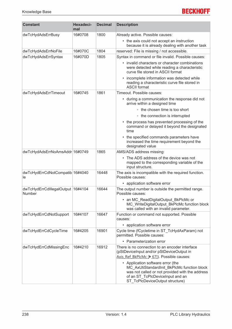
Knowledge Base
PLC Library Hydraulics238 Version: 1.4
Constant Hexadeci-mal
Decimal Description
dwTcHydAdsErrBusy 16#0708 1800 Already active. Possible causes:• the axis could not accept an instruction
because it is already dealing with another taskdwTcHydAdsErrNoFile 16#070C 1804 reserved: File is missing / not accessible.dwTcHydAdsErrSyntax 16#070D 1805 Syntax in command or file invalid. Possible causes:
• invalid characters or character combinationswere detected while reading a characteristiccurve file stored in ASCII format
• incomplete information was detected whilereading a characteristic curve file stored inASCII format
dwTcHydAdsErrTimeout 16#0745 1861 Timeout. Possible causes:• during a communication the response did not
arrive within a designed time◦ the chosen time is too short◦ the connection is interrupted
• the process has prevented processing of thecommand or delayed it beyond the designatedtime
• the specified commands parameters haveincreased the time requirement beyond thedesignated value
dwTcHydAdsErrNoAmsAddr 16#0749 1865 AMS/ADS address missing:• The ADS address of the device was not
mapped to the corresponding variable of theinput structure.
dwTcHydErrCdNotCompatible
16#4040 16448 The axis is incompatible with the required function.Possible causes:
• application software errordwTcHydErrCdIllegalOutputNumber
16#4104 16644 The output number is outside the permitted range.Possible causes:
• an MC_ReadDigitalOutput_BkPlcMc orMC_WriteDigitalOutput_BkPlcMc function blockwas called with an invalid parameter.
dwTcHydErrCdNotSupport 16#4107 16647 Function or command not supported. Possiblecauses:
• application software errordwTcHydErrCdCycleTime 16#4205 16901 Cycle time (fCycletime in ST_TcHydAxParam) not
permitted. Possible causes:• Parameterization error
dwTcHydErrCdMissingEnc 16#4210 16912 There is no connection to an encoder interface(pStDeviceInput and/or pStDeviceOutput inAxis_Ref_BkPlcMc [} 67]). Possible causes:
• Application software error (theMC_AxUtiStandardInit_BkPlcMc function blockwas not called or not provided with the addressof an ST_TcPlcDeviceInput and anST_TcPlcDeviceOutput structure)

Knowledge Base
PLC Library Hydraulics 239Version: 1.4
Constant Hexadeci-mal
Decimal Description
dwTcHydErrCdMissingDrive 16#4212 16914 There is no connection to a drive interface(pStDeviceInput and/or pStDeviceOutput inAxis_Ref_BkPlcMc [} 67]). Possible causes:
• Application software error (theMC_AxUtiStandardInit_BkPlcMc function blockwas not called or not provided with the addressof an ST_TcPlcDeviceInput and anST_TcPlcDeviceOutput structure)
dwTcHydErrCdCannotSynchronize
16#421A 16922 Start distance inadequate when anMC_GearInPos_BkPlcMc() function block is called.Possible causes:
• the axis is too close to the sync point when thefunction block is activated
• the dynamic axis parameters are inadequatedwTcHydErrCdIllegalGearFactor
16#421B 16923 The parameters of a gear coupling are not permitted.Possible causes:
• the parameter of the function block is notpermitted
dwTcHydErrCdSoftEnd 16#4222 16930 The target position is located on the far side of anactive software limit switch, and is therefore notpermitted.
dwTcHydErrCdLowDist 16#4228 16936 The travel distance is unacceptably small.dwTcHydErrCdIllegalStartType
16#4239 16953 Invalid start type.
dwTcHydErrCdCommandBufferOverflow
16#423F 16959 Command buffer is full.
dwTcHydErrCdEncLostCamm
16#4253 16979 Reserved. Not supported.
dwTcHydErrCdCtrlEnaLost 16#4260 16992 Controller enable was withdrawn during the motion.Possible causes:
• the axis enable was withdrawn at anunexpected time due to a machine logic signal
• application software errordwTcHydErrCdEncNoCammFound
16#429C 17052 Reserved. Not supported.
dwTcHydErrCdEncNoCammEnd
16#429D 17053 Reserved. Not supported.
dwTcHydErrCdEncNoSyncPulse
16#429E 17054 Reserved. Not supported.
dwTcHydErrCdAcc 16#4309 17161 The acceleration is not acceptable.dwTcHydErrCdDec 16#430A 17162 The deceleration is not acceptable.dwTcHydErrCdJerk 16#430B 17163 The jerk limitation is invalid.dwTcHydErrCdPtrPlcMc 16#4345 17221 No connection to one of the required axis interfaces
(pStDeviceInput or pStDeviceOutput inAxis_Ref_BkPlcMc [} 67]).
dwTcHydErrCdPtrMcPlc 16#4346 17222 No connection to one of the required axis interfaces(pStDeviceInput or pStDeviceOutput inAxis_Ref_BkPlcMc [} 67]).
dwTcHydErrCdCtrlEna 16#4356 17238 Movement without controller enable is not permitted.dwTcHydErrCdNegFdEna 16#4357 17239 Movement in the direction of reducing positions
without the negative direction advance enable is notpermitted.
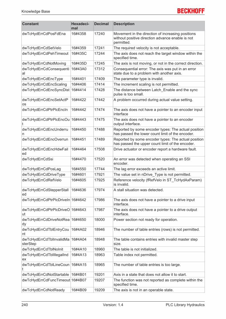
Knowledge Base
PLC Library Hydraulics240 Version: 1.4
Constant Hexadeci-mal
Decimal Description
dwTcHydErrCdPosFdEna 16#4358 17240 Movement in the direction of increasing positionswithout positive direction advance enable is notpermitted.
dwTcHydErrCdSetVelo 16#4359 17241 The required velocity is not acceptable.dwTcHydErrCdPehTimeout 16#435C 17244 The axis does not reach the target window within the
specified time.dwTcHydErrCdNotMoving 16#435D 17245 The axis is not moving, or not in the correct direction.dwTcHydErrCdConsequential
16#43A0 17312 Consequential error: The axis was put in an errorstate due to a problem with another axis.
dwTcHydErrCdEncType 16#4401 17409 The parameter type is invalid.dwTcHydErrCdEncScaling 16#4406 17414 The increment scaling is not permitted.dwTcHydErrCdEncSyncDist 16#4414 17428 The distance between Latch_Enable and the sync
pulse is too small.dwTcHydErrCdEncSetActPos
16#4422 17442 A problem occurred during actual value setting.
dwTcHydErrCdPtrPlcEncIn 16#4442 17474 The axis does not have a pointer to an encoder inputinterface
dwTcHydErrCdPtrPlcEncOut
16#4443 17475 The axis does not have a pointer to an encoderoutput interface.
dwTcHydErrCdEncUnderrun
16#4450 17488 Reported by some encoder types: The actual positionhas passed the lower count limit of the encoder.
dwTcHydErrCdEncOverrun 16#4451 17489 Reported by some encoder types: The actual positionhas passed the upper count limit of the encoder.
dwTcHydErrCdEncHdwFailed
16#4464 17508 Drive actuator or encoder report a hardware fault.
dwTcHydErrCdSsi 16#4470 17520 An error was detected when operating an SSIencoder.
dwTcHydErrCdPosLag 16#4550 17744 The lag error exceeds an active limit.dwTcHydErrCdDriveType 16#4601 17921 The value set in nDrive_Type is not permitted.dwTcHydErrCdRefVelo 16#4605 17925 Reference velocity (fRefVelo in ST_TcHydAxParam)
is invalid.dwTcHydErrCdStepperStalled
16#4636 17974 A stall situation was detected.
dwTcHydErrCdPtrPlcDriveIn 16#4642 17986 The axis does not have a pointer to a drive inputinterface.
dwTcHydErrCdPtrPlcDriveOut
16#4643 17987 The axis does not have a pointer to a drive outputinterface.
dwTcHydErrCdDriveNotReady
16#4650 18000 Power section not ready for operation.
dwTcHydErrCdTblEntryCount
16#4A02 18946 The number of table entries (rows) is not permitted.
dwTcHydErrCdTblInvalidMasterStep
16#4A04 18948 The table contains entries with invalid master stepsize.
dwTcHydErrCdTblNoInit 16#4A10 18960 The table is not initialized.dwTcHydErrCdTblIllegalIndex
16#4A13 18963 Table index not permitted.
dwTcHydErrCdTblLineCount
16#4A15 18965 The number of table entries is too large.
dwTcHydErrCdNotStartable 16#4B01 19201 Axis in a state that does not allow it to start.dwTcHydErrCdFuncTimeout 16#4B07 19207 The function was not reported as complete within the
specified time.dwTcHydErrCdNotReady 16#4B09 19209 The axis is not in an operable state.

Knowledge Base
PLC Library Hydraulics 241Version: 1.4
Constant Hexadeci-mal
Decimal Description
dwTcHydErrCdHomingType 16#4F00 20224 Referencing method (nEnc_HomingType inST_TcHydAxParam) is not permitted.
dwTcHydErrCdEncCutOff 16#4F01 20225 The limit frequency for the actual value acquisitionhas been exceeded.
dwTcHydErrCdIllegalDistance
16#4F02 20226 Distance is invalid: zero or negative.
dwTcHydErrEncDisconected
16#4FF0 20464 Encoder hardware is uncoupled. Possible causes:• the fieldbus connection is interrupted• the power supply for the device is not available• the device is faulty• another device, which is located in the fieldbus
connection between the controller and thedevice, has no power supply or is faulty
dwTcHydErrDriveDisconected
16#4FF1 20465 Drive hardware is uncoupled. Possible causes:• the fieldbus connection is interrupted• the power supply for the device is not available• the device is faulty• another device, which is located in the fieldbus
connection between the controller and thedevice, has no power supply or is faulty
dwTcHydErrDistanceInsufficient
16#4FF2 20466 The travel path is inadequate.
Device-specific error codes of function block MC_Power_BkPlcMc
These values appear at the ErrorID output of an MC_Power_BkPlcMc function block, if an error is reportedby the external device.

Knowledge Base
PLC Library Hydraulics242 Version: 1.4
Constant Hexadeci-mal
Decimal Description
dwTcHydErrCdAX2000MainPwrTmOut
16#0001 1 Only for AX2000: no feedback by the mains contactor(timeout during waiting forST_TcPlcMcAx2000In.bPowerOk).
dwTcHydErrCdAX2000MainPwrFault
16#0002 2 Only for AX2000: negative edge on feedback frommains contactor (ST_TcPlcMcAx2000In.bPowerOk).
dwTcHydErrCdAX2000PwrStageTmOut
16#0003 3 Only for AX2000: no feedback from AX output stage(timeout during waiting forST_TcPlcMcAx2000In.DriveState[3].6, no Ready).
dwTcHydErrCdAX2000PwrStageFault
16#0004 4 Only for AX2000: Negative edge of AX output stage(ST_TcPlcMcAx2000In.DriveState[3].6, no Ready).
dwTcHydErrCdAX2000ReportsError
16#0005 5 Only for AX2000: error message from AX device(ST_TcPlcMcAx2000In.DriveState[3].7 orST_TcPlcMcAx2000In.DriveError<>0).
dwTcHydErrCdAX2000ErrorI2T
16#0006 6 Only for AX2000: I2T error message from AX outputstage (ST_TcPlcMcAx2000In.DriveState[0].0).
dwTcHydErrCdAX2000ErrorChopper
16#0007 7 Only for AX2000: brake resistor of the AX outputstage faulty (ST_TcPlcMcAx2000In.DriveState[0].1).
dwTcHydErrCdAX2000ErrorWatchDog
16#0008 8 Only for AX2000: watchdog (timeout duringcommunication) of the AX output stage was triggered(ST_TcPlcMcAx2000In.DriveState[0].3).
dwTcHydErrCdAX2000ErrorPwrLine
16#0009 9 Only for AX2000: supply error reported by AX outputstage (ST_TcPlcMcAx2000In.DriveState[0].4).
dwTcHydErrCdAX2000ConnectionLost
16#000A 10 Only for AX2000: The connection to the AX device isbroken or substantially disrupted(ST_TcPlcMcAx2000In.BoxState<>0).
dwTcHydErrCdAX2000ConnectionTmOut
16#000B 11 Only for AX2000: The communication with the AXdevice could not be established (timeout).
dwTcHydErrCdKL2531OverTemp
16#0001 1 Only for KL2531/KL2541: The KL2531/KL2541terminal reports overtemperature alarm.
dwTcHydErrCdKL2531UnderVoltage
16#0002 2 Only for KL2531/KL2541: The KL2531/KL2541terminal reports inadequate supply voltage on thepower rail.
16#0003 3 Only for KL2531/KL2541: Reserved.dwTcHydErrCdKL2531OpenLoadA
16#0004 4 Only for KL2531/KL2541: The KL2531/KL2541terminal reports broken wire on the A-side.
dwTcHydErrCdKL2531OpenLoadB
16#0005 5 Only for KL2531/KL2541: The KL2531/KL2541terminal reports broken wire on the B-side.
dwTcHydErrCdKL2531OverCurrentA
16#0006 6 Only for KL2531/KL2541: The KL2531/KL2541terminal reports overcurrent at output stage A.
dwTcHydErrCdKL2531OverCurrentB
16#0007 7 Only for KL2531/KL2541: The KL2531/KL2541terminal reports overcurrent at output stage B.
dwTcHydErrCdKL2531NotReady
16#0008 8 Only for KL2531/KL2541: The terminal reports aoutput stage problem (enabled, not ready).
dwTcHydErrCdKL2531ConnectionLost
16#000A 10 Only for KL2531/KL2541: The connection to theterminal is broken or substantially disrupted(ST_TcPlcMcDriveIn.uiBoxState<>0).
dwTcHydErrCdKL2531ConnectionTmOut
16#000B 11 Only for KL2531/KL2541: The communication withthe terminal could not be established (timeout).
ADS Codes
These constants are accepted by the MC_AxAdsReadDecoder and MC_AxAdsWriteDecoder functionblocks.
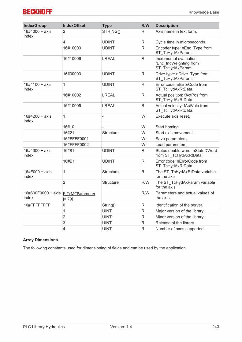
Knowledge Base
PLC Library Hydraulics 243Version: 1.4
IndexGroup IndexOffset Type R/W Description16#4000 + axisindex
2 STRING() R Axis name in text form.
4 UDINT R Cycle time in microseconds.16#10003 UDINT R Encoder type: nEnc_Type from
ST_TcHydAxParam.16#10006 LREAL R Incremental evaluation:
fEnc_IncWeighting fromST_TcHydAxParam.
16#30003 UDINT R Drive type: nDrive_Type fromST_TcHydAxParam.
16#4100 + axisindex
1 UDINT R Error code: nErrorCode fromST_TcHydAxRtData.
16#10002 LREAL R Actual position: fActPos fromST_TcHydAxRtData.
16#10005 LREAL R Actual velocity: fActVelo fromST_TcHydAxRtData.
16#4200 + axisindex
1 - W Execute axis reset.
16#10 - W Start homing.16#21 Structure W Start axis movement.16#FFFF0001 - W Save parameters.16#FFFF0002 - W Load parameters.
16#4300 + axisindex
16#81 UDINT R Status double word: nStateDWordfrom ST_TcHydAxRtData.
16#B1 UDINT R Error code: nErrorCode fromST_TcHydAxRtData.
16#F000 + axisindex
1 Structure R The ST_TcHydAxRtData variablefor the axis.
2 Structure R/W The ST_TcHydAxParam variablefor the axis.
16#800F0000 + axisindex
E_TcMCParameter[} 79]
R/W Parameters and actual values ofthe axis.
16#FFFFFFFF 0 String() R Identification of the server.1 UINT R Major version of the library.2 UINT R Minor version of the library.3 UINT R Release of the library.4 UINT R Number of axes supported
Array Dimensions
The following constants used for dimensioning of fields and can be used by the application.

Knowledge Base
PLC Library Hydraulics244 Version: 1.4
Constant DescriptionciBkPlcMc_CamSwitchRef_MinIdx Lower boundary index on an array[] of CAMSWITCH_REF_BkPlcMc
[} 69], supplied to blocks of type MC_DigitalCamSwitch_BkPlcMc[} 48]
ciBkPlcMc_CamSwitchRef_MaxIdx Upper boundary index on an array[] of CAMSWITCH_REF_BkPlcMc[} 69], supplied to blocks of type MC_DigitalCamSwitch_BkPlcMc[} 48]
ciBkPlcMc_TrackRef_MinIdx Lower boundary index on an array[] of TRACK_REF_BkPlcMc [} 109],supplied to blocks of type MC_DigitalCamSwitch_BkPlcMc [} 48]
ciBkPlcMc_TrackRef_MaxIdx Upper boundary index on an array[] of TRACK_REF_BkPlcMc [} 109],supplied to blocks of type MC_DigitalCamSwitch_BkPlcMc [} 48]
Logger Levels
The following constants are used for the specification of the level, from which messages are included in thelogger function of the library.
Constant DescriptiondwTcHydLogLevel_None No loggingdwTcHydLogLevel_Errors Only error messagesdwTcHydLogLevel_Warnings Error messages and warningsdwTcHydLogLevel_Actions Error messages, warnings and activities
Logger Sources
The following constants are used to specify the source of messages in the logger function of the library.
Constant DescriptiondwTcHydLogSource_Library A function block of the hydraulics librarydwTcHydLogSource_LibExt_2R2V A function block of the 2R2V librarydwTcHydLogSource_Application A function block of the applicationdwTcHydLogSource_ApplicationFramework A function block of an application platform
Logger Argument Types
The following constants are used to specify the type of an optional parameter for a message in the loggerfunction of the library.
Constant DescriptiondwTcHydLogArgType_DInt The message contains a parameter of type DINT. The message text
must include a placeholder in the form %d.dwTcHydLogArgType_LReal The message contains a parameter of type LREAL. The message
text must include a placeholder in the form %f.dwTcHydLogArgType_String The message contains a parameter of type STRING. The message
text must include a placeholder in the form %s.
5.3 ValveThe valve is generally the actuator, which controls the axis. For continuous valves, a distinction is madebetween:
• Servo valve• Proportional valve• Control valve

Knowledge Base
PLC Library Hydraulics 245Version: 1.4
Servo valve
These valves control large oil flows via small electrical signals
• A small torque motor controls the connected control oil, thereby adjusting the slider of the main stage.• Often multi-stage design• High responsiveness and controllability
Proportional valve
A coil current generates a proportional force, which moves the valve slider against the force of a spring.
Compared to servo valve:
• Longer step response time• Higher current consumption• Larger hysteresis• More robust against contamination• Attractive price
Control valve:
A proportional valve, for which the slider position is measured and automatically adjusted:
• Shorter step response time• Smaller hysteresis• Smaller load reaction• More complex and more expensive than proportional valves• Electronics on the valve or in the control cabinet
Basic principles of reading valve data sheets
A continuous valve is usually used as actuator for a controller. The designs of valves from differentmanufacturers or different types may differ quite significantly. In order to adapt the output scaling to theparticular situation, the valve data sheet for the continuous valve must be available during commissioning. Avalve has a number of hydraulic ports. A and B are the valve outputs; A is connected to the cylinder side withthe larger piston area, B is connected to the cylinder side with the smaller piston area. P and T represent thesupply connections. P is the pressure line, and T is the return line to the tank.
NOTE! In the hydraulics library, the A-side is always the side under positive pressure, the B-side isthe side under negative pressure.
In many cases the valve slide has to move slightly before an oil flow can be detected. This stroke is listed inthe valve data sheet under overlap.
NOTE! The data sheet may indicate an overlapped valve, although this overlap is compensated inthe valve electronics.

Knowledge Base
PLC Library Hydraulics246 Version: 1.4
The characteristic volume flow curve shows the key information for the valve. The diagram above shows thatthe piston itself has an overlap of 20%, which was reduced to 5% in the valve electronics. As a result, nooverlap compensation via the hydraulics library is required.
NOTE! The fact that overlap compensation was carried out in the valve does not make it a zerooverlap valve, and the axis is therefore only capable of position control to a limited degree.
The diagram shows that the oil flow in the A-chamber of the piston is greater than the oil flow in the B-chamber. This asymmetry indicates an area compensation in valve, in this case with a ratio of 11:6.
5.4 Configuration of an axisIn contrast to the Beckhoff NC, the axis in the hydraulic library is configured by the application itself. Thismeans that the function blocks for operating an axis (read actual value, generate set values, generateposition rules, linearization and output) must be called up individually.
All function blocks work on a common axis reference, which must be created globally. If there is more thanone axis, the axis references must be created as an array.
In addition to the axis reference (AXIS_REF_BkPlcMc [} 67]), the I/O structures ST_TcPlcDeviceInput [} 104]and ST_TcPlcDeviceOutput [} 106] must be declared for each axis. If other sensors such as pressure or loadcells are used in the application in addition to position detection, the I/O value must be set in the application.The parameterization of the scaling can be managed in the fCustomerData[] section of the axis. For eachaxis 20 customer-specific data are provided in this section. This data is saved via the axis, loaded anddisplayed in the PLcMcManager. For the display in the PlcMcManager the label can be changed by declaringthe structure ST_TcMcAuxDataLabels [} 103].
To view messages a ST_TcPlcMcLogBuffer [} 107] is declared. This buffer is shared by all axes.

Knowledge Base
PLC Library Hydraulics 247Version: 1.4
The individual function blocks required for a complete axis are listed and described below.
5.4.1 FB_Init
The function block loads the parameters from the given file path and transfers them to the axis reference.The function block also links the input and output structures to the axis reference.All parameters are stored in binary form in an Axis name.dat file. Once the parameters have been loaded successfully, the bParamsEnable flag in the axis reference becomesTRUE. Only now may all other axis-related function blocks be called up, otherwise calculations would becarried out with incorrect parameters.The Init function block should be called cyclically to check the pointer addresses. Variables that are passedas addresses are marked with the prefix "p".
5.4.2 FB_Encoder
The actual value is read from the input structure via the selected encoder type and converted into a position[mm] and velocity [mm/s].
If the actual values are very noisy, it is possible to filter them via a moving average(MC_AxUtiSlidingAverage_BkPlcMc [} 191]) or a Pt1 element (MC_AxUtiPT1_BkPlcMc [} 189]). In addition, it ispossible to build custom filters.

Knowledge Base
PLC Library Hydraulics248 Version: 1.4
The filter function blocks must be called after the encoder. The variable to be filtered must be passed to thefilter function block at the input, and the corresponding variable of this axis reference can be written at theoutput of the filter function block. This causes the old noisy value to be overwritten by a new, stabilizedvalue.
NOTE! If a heavily filtered actual value is used for control purposes, the dynamics can be affecteddue to the filter jump response.
Additional function blocks are available for reading in pressure and force values. The function block to beused depends on the variable to be measured. In contrast to position determination, for force and pressuredetermination the mapping interface and terminal monitoring must be provided by the application.
5.4.3 FB_Runtime
The setpoint generator is integrated in function block FB_Runtime [} 167]. It calculates the corresponding setposition, set velocity and, if applicable, also the set pressure for each cycle. In addition to generating setvalues, the runtime function block also deals with position control. The following setpoint generators are provided:
• iTcMc_ProfileCtrlBased:The profile generation takes place via an acceleration phase, a constant velocity phase and a brakephase.
• iTcMc_ProfilJerkBasiertThe profile generation takes place via a jerk phase, an acceleration phase, a jerk phase, a constantvelocity phase, a jerk phase, a brake phase and a jerk phase.
• ProfilBufferedJerkThe profile generation takes place in buffered form via up to 12 velocity profiles, which must be knownwhen the axis is started. The individual velocity profiles are structured as in "iTcMc_ProfileJerkBased".
In addition to the various set value profiles, it is possible to operate the axis as a time-based axis or adisplacement-based axis via the parameter timebased.
If the setpoint generator is to follow a curve not determined by itself, the function blockMC_AxRtSetExtGenValues_BkPlcMc [} 180] must be called and the set position must be passed here. The setvalue can then come from the NCI's setpoint generator, for example.
The position controller is integrated in the setpoint generator.
5.4.4 FB_ReglerIf a force or pressure regulator is required in the application, it must be called up after the setpoint generatorand before the linearization function block.
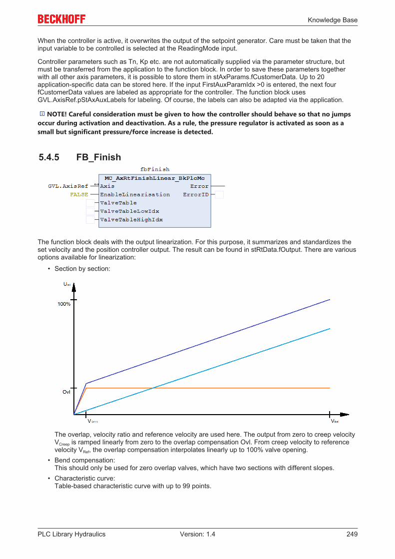
Knowledge Base
PLC Library Hydraulics 249Version: 1.4
When the controller is active, it overwrites the output of the setpoint generator. Care must be taken that theinput variable to be controlled is selected at the ReadingMode input.
Controller parameters such as Tn, Kp etc. are not automatically supplied via the parameter structure, butmust be transferred from the application to the function block. In order to save these parameters togetherwith all other axis parameters, it is possible to store them in stAxParams.fCustomerData. Up to 20application-specific data can be stored here. If the input FirstAuxParamIdx >0 is entered, the next fourfCustomerData values are labeled as appropriate for the controller. The function block usesGVL.AxisRef.pStAxAuxLabels for labeling. Of course, the labels can also be adapted via the application.
NOTE! Careful consideration must be given to how the controller should behave so that no jumpsoccur during activation and deactivation. As a rule, the pressure regulator is activated as soon as asmall but significant pressure/force increase is detected.
5.4.5 FB_Finish
The function block deals with the output linearization. For this purpose, it summarizes and standardizes theset velocity and the position controller output. The result can be found in stRtData.fOutput. There are variousoptions available for linearization:
• Section by section:
The overlap, velocity ratio and reference velocity are used here. The output from zero to creep velocityVCreep is ramped linearly from zero to the overlap compensation Ovl. From creep velocity to referencevelocity VRef, the overlap compensation interpolates linearly up to 100% valve opening.
• Bend compensation:This should only be used for zero overlap valves, which have two sections with different slopes.
• Characteristic curve:Table-based characteristic curve with up to 99 points.
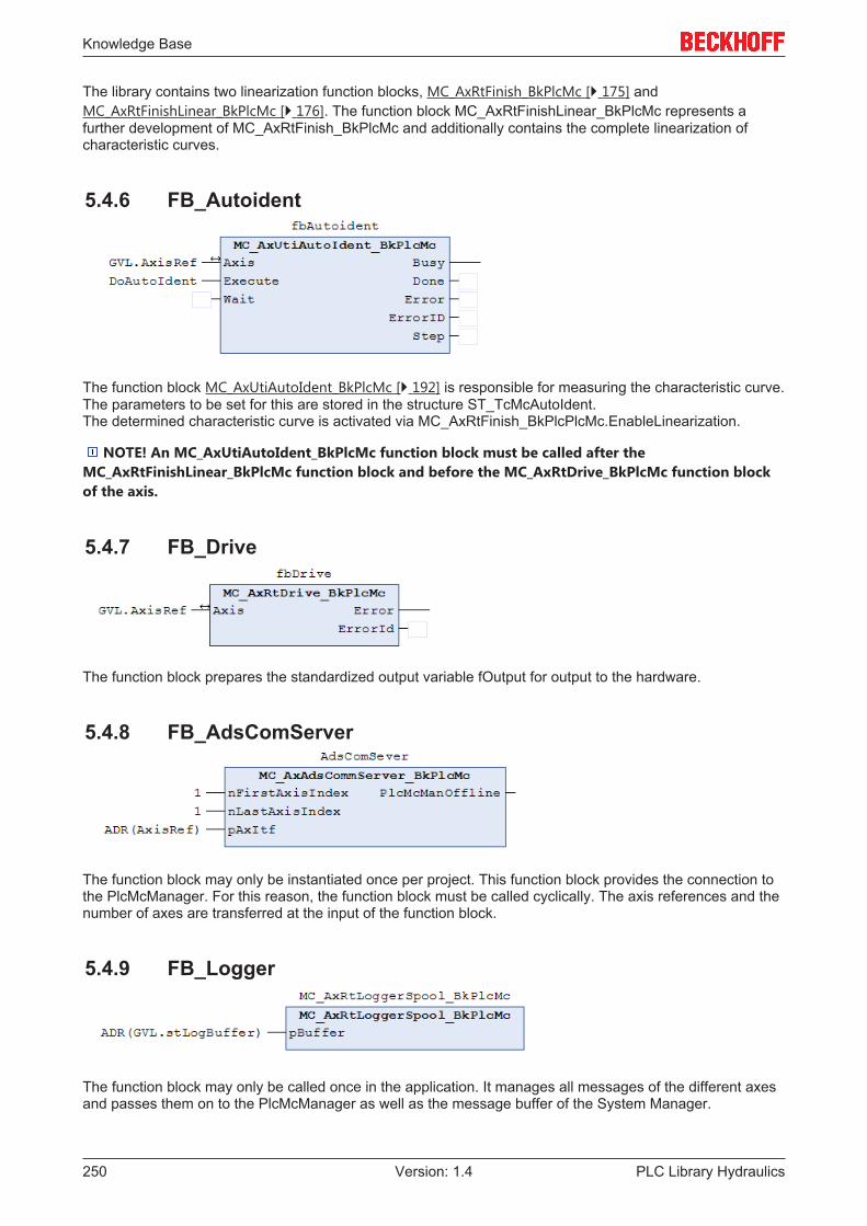
Knowledge Base
PLC Library Hydraulics250 Version: 1.4
The library contains two linearization function blocks, MC_AxRtFinish_BkPlcMc [} 175] andMC_AxRtFinishLinear_BkPlcMc [} 176]. The function block MC_AxRtFinishLinear_BkPlcMc represents afurther development of MC_AxRtFinish_BkPlcMc and additionally contains the complete linearization ofcharacteristic curves.
5.4.6 FB_Autoident
The function block MC_AxUtiAutoIdent_BkPlcMc [} 192] is responsible for measuring the characteristic curve.The parameters to be set for this are stored in the structure ST_TcMcAutoIdent.The determined characteristic curve is activated via MC_AxRtFinish_BkPlcPlcMc.EnableLinearization.
NOTE! An MC_AxUtiAutoIdent_BkPlcMc function block must be called after theMC_AxRtFinishLinear_BkPlcMc function block and before the MC_AxRtDrive_BkPlcMc function blockof the axis.
5.4.7 FB_Drive
The function block prepares the standardized output variable fOutput for output to the hardware.
5.4.8 FB_AdsComServer
The function block may only be instantiated once per project. This function block provides the connection tothe PlcMcManager. For this reason, the function block must be called cyclically. The axis references and thenumber of axes are transferred at the input of the function block.
5.4.9 FB_Logger
The function block may only be called once in the application. It manages all messages of the different axesand passes them on to the PlcMcManager as well as the message buffer of the System Manager.
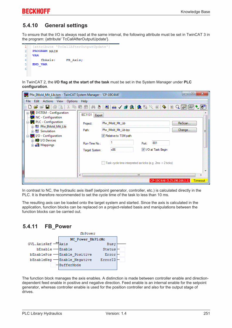
Knowledge Base
PLC Library Hydraulics 251Version: 1.4
5.4.10 General settingsTo ensure that the I/O is always read at the same interval, the following attribute must be set in TwinCAT 3 inthe program: {attribute' TcCallAfterOutputUpdate'}.
In TwinCAT 2, the I/O flag at the start of the task must be set in the System Manager under PLCconfiguration.
In contrast to NC, the hydraulic axis itself (setpoint generator, controller, etc.) is calculated directly in thePLC. It is therefore recommended to set the cycle time of the task to less than 10 ms.
The resulting axis can be loaded onto the target system and started. Since the axis is calculated in theapplication, function blocks can be replaced on a project-related basis and manipulations between thefunction blocks can be carried out.
5.4.11 FB_Power
The function block manages the axis enables. A distinction is made between controller enable and direction-dependent feed enable in positive and negative direction. Feed enable is an internal enable for the setpointgenerator, whereas controller enable is used for the position controller and also for the output stage ofdrives.

Knowledge Base
PLC Library Hydraulics252 Version: 1.4
5.5 The PlcMcManagerThe PlcMcManager supports commissioning and testing of axes, which are automated using the hydraulicslibrary. It visualizes the actual state and enables access to parameters and triggering of commands.
NOTE! The PlcMcManager is not intended for operating machines and systems. It is not asubstitute for a user interface.
Safety instructions
Attention
Unexpected machine behaviorThe commands triggered by the PlcMcManager can obstruct automatic actions and re-sponses of the control software obstruct or influence them in an unexpected or undesirabledirection. This may result in unexpected and dangerous movements.
Installation
For TC2: A license-free copy of the PlcMcManager is provided with the library or the documentation. Selecta suitable path, then create a shortcut on the desktop of the PC. Without such a shortcut, the PlcMcManagercan only be started from Explorer.
For TC3: When downloading the library, a license-free copy of the PlcMcManager is created in the directoryC:\TwinCAT\Functions\TF5810-TC3_Hydraulics-Positioning. If your TwinCAT not installed under to C: or inanother directory, the path must be adjusted accordingly.
Running the PlcMcManager
If the tool is stored on the PC, it can be started by double-clicking.
Offline display of a parameter file
In the menu bar under Online you will find the Offline file mode, where a dialog for selecting an axisparameter file of type DAT is offered. When a file is opened, the axis parameters are show like in onlinemode, as far as possible.
NOTE! No actual axis states are shown, and no axis commands can be triggered. This also applies ifthe displayed parameters belong to an axis, to which access would be possible.
Online operation
If the runtime system with the library function blocks is not present on the PC on which the PlcMcManager isrunning, the target system has to be selected first. In the menu bar under Online you will find the Targetdialog, where the computers are listed that are entered as Remote Computers in TwinCAT SystemService on the AMS Router tab.

Knowledge Base
PLC Library Hydraulics 253Version: 1.4
By selecting a Remote Computer, the communication with the runtime system is activated automatically. Ifthe runtime system with the library function blocks is present on the PC on which the PlcMcManager isrunning, the communication with the runtime system can be activated with Login via the menu bar underOnline.
In the current versions the PlcMcManager is prepared for use under TC3. To establish the connection atruntime, it checks the expected ADS addresses for both TC2 and TC3. This may take several seconds,particularly if a network connection is used. The details shown below should then appear.
1. Shows the port and the server used for the communication with the runtime system.2. The mode is displayed. Since no axis has been selected up to this point, the PlcMcManager is still in
OFFLINE mode.3. Shows the version information of the library used by the PLC application.
If these details do not appear after a few seconds, the connection has failed. This can have a number ofreasons:
• No target system was selected, despite the fact that the application is not running on the samecomputer as the PlcMcManager.
• The PLC application does not contain a MC_AxAxAdsCommServer_BkPlcMc [} 198] function block ordoes not call it.
• The application is not running on the selected target system.• No connection to the selected target system.• The PC on which the PlcMcManager is running has no access rights to the selected target system.• The PLC is not running.
If a dialog with an error message appears at this point, the connection to the target system is disturbed(timeout), or the PlcMcManager and the library used in the application are not compatible. Incompatibility isusually due to a new library version being used, without updating the PlcMcManager.
Many parameter input fields have a "?" field on the left-hand side. This can be used to call up a briefexplanation of the parameter.
Example: Explanation of the parameter <Global.creep velocity:
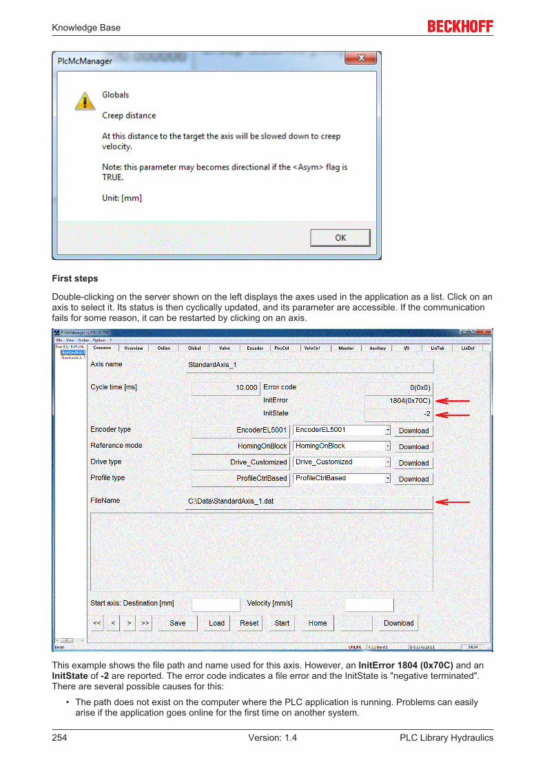
Knowledge Base
PLC Library Hydraulics254 Version: 1.4
First steps
Double-clicking on the server shown on the left displays the axes used in the application as a list. Click on anaxis to select it. Its status is then cyclically updated, and its parameter are accessible. If the communicationfails for some reason, it can be restarted by clicking on an axis.
This example shows the file path and name used for this axis. However, an InitError 1804 (0x70C) and anInitState of -2 are reported. The error code indicates a file error and the InitState is "negative terminated".There are several possible causes for this:
• The path does not exist on the computer where the PLC application is running. Problems can easilyarise if the application goes online for the first time on another system.
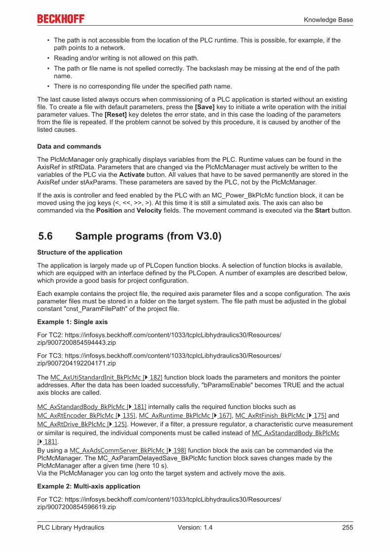
Knowledge Base
PLC Library Hydraulics 255Version: 1.4
• The path is not accessible from the location of the PLC runtime. This is possible, for example, if thepath points to a network.
• Reading and/or writing is not allowed on this path.• The path or file name is not spelled correctly. The backslash may be missing at the end of the path
name.• There is no corresponding file under the specified path name.
The last cause listed always occurs when commissioning of a PLC application is started without an existingfile. To create a file with default parameters, press the [Save] key to initiate a write operation with the initialparameter values. The [Reset] key deletes the error state, and in this case the loading of the parametersfrom the file is repeated. If the problem cannot be solved by this procedure, it is caused by another of thelisted causes.
Data and commands
The PlcMcManager only graphically displays variables from the PLC. Runtime values can be found in theAxisRef in stRtData. Parameters that are changed via the PlcMcManager must actively be written to thevariables of the PLC via the Activate button. All values that have to be saved permanently are stored in theAxisRef under stAxParams. These parameters are saved by the PLC, not by the PlcMcManager.
If the axis is controller and feed enabled by the PLC with an MC_Power_BkPlcMc function block, it can bemoved using the jog keys (<, <<, >>, >). At this time it is still a simulated axis. The axis can also becommanded via the Position and Velocity fields. The movement command is executed via the Start button.
5.6 Sample programs (from V3.0)Structure of the application
The application is largely made up of PLCopen function blocks. A selection of function blocks is available,which are equipped with an interface defined by the PLCopen. A number of examples are described below,which provide a good basis for project configuration.
Each example contains the project file, the required axis parameter files and a scope configuration. The axisparameter files must be stored in a folder on the target system. The file path must be adjusted in the globalconstant "cnst_ParamFilePath" of the project file.
Example 1: Single axis
For TC2: https://infosys.beckhoff.com/content/1033/tcplcLibhydraulics30/Resources/zip/9007200854594443.zip
For TC3: https://infosys.beckhoff.com/content/1033/tcplcLibhydraulics30/Resources/zip/9007204192204171.zip
The MC_AxUtiStandardInit_BkPlcMc [} 182] function block loads the parameters and monitors the pointeraddresses. After the data has been loaded successfully, "bParamsEnable" becomes TRUE and the actualaxis blocks are called.
MC_AxStandardBody_BkPlcMc [} 181] internally calls the required function blocks such asMC_AxRtEncoder_BkPlcMc [} 135], MC_AxRuntime_BkPlcMc [} 167], MC_AxRtFinish_BkPlcMc [} 175] andMC_AxRtDrive_BkPlcMc [} 125]. However, if a filter, a pressure regulator, a characteristic curve measurementor similar is required, the individual components must be called instead of MC_AxStandardBody_BkPlcMc[} 181].By using a MC_AxAdsCommServer_BkPlcMc [} 198] function block the axis can be commanded via thePlcMcManager. The MC_AxParamDelayedSave_BkPlcMc function block saves changes made by thePlcMcManager after a given time (here 10 s).Via the PlcMcManager you can log onto the target system and actively move the axis.
Example 2: Multi-axis application
For TC2: https://infosys.beckhoff.com/content/1033/tcplcLibhydraulics30/Resources/zip/9007200854596619.zip

Knowledge Base
PLC Library Hydraulics256 Version: 1.4
For TC3: https://infosys.beckhoff.com/content/1033/tcplcLibhydraulics30/Resources/zip/9007204192206731.zip
The example illustrates a configuration with arrays of function blocks and structures. The range of functionscorresponds to example 1.
Example 3: Pressure-controlled braking
For TC2: https://infosys.beckhoff.com/content/1033/tcplcLibhydraulics30/Resources/zip/1599857803.zip
For TC3: https://infosys.beckhoff.com/content/1033/tcplcLibhydraulics30/Resources/zip/9007204192209291.zip
The example shows how the pressure regulator MC_AxCtrlSlowDownOnPressure_BkPlcMc [} 119] throttlesthe feed rate of an axis depending on the pressure. In this example, the controller becomes active when theactual pressure exceeds the set pressure. Since the result is transferred via an application code to"fLagCtrlOutput", the controller must be called after the setpoint generator. Otherwise, fLagCtrlOutput wouldbe overwritten by the position controller in MC_AxRuntime_BkPlcMc [} 167].If a command is started in the PlcMcManager with a velocity of 100 mm/s and a position of 500 mm, forexample, the scope shows that the pressure increases continuously with increasing position. At a position of400 mm, the system has reached the set pressure of 50 bar and stops.
Example 5: Move function blocks
For TC2: https://infosys.beckhoff.com/content/1033/tcplcLibhydraulics30/Resources/zip/1599859979.zip
For TC3: https://infosys.beckhoff.com/content/1033/tcplcLibhydraulics30/Resources/zip/9007204192288651.zip
In this example, various function blocks are used for motion control. If the variable bStart becomes TRUE,the state machine starts the axis with MC_MoveAbsolute_BkPlcMc [} 60] to the position 500 mm. When theaxis has reached the target and the target window conditions are met (in PosRang, in TargetRange forTargetFilterTime and in BrakeDistance), a MC_MoveVelocity_BkPlcMc [} 64] automatically starts with avelocity of 400 mm/s. This velocity remains active for 5 seconds and is then terminated withMC_Stop_BkPlcMc [} 66], so that the axis comes to a standstill. This is followed by a relative movement of100 mm with MC_MoveRelative_BkPlcMc [} 63] and a move to position 0.0 mm. Different acceleration anddeceleration ramps are used in the different motion profiles.
Example 6: Time ramp generator
For TC2: https://infosys.beckhoff.com/content/1033/tcplcLibhydraulics30/Resources/zip/1599862155.zip
For TC3: https://infosys.beckhoff.com/content/1033/tcplcLibhydraulics30/Resources/zip/9007204192291211.zip
An axis without encoder cannot be controlled via the standard setpoint generator. For this type of axis,iTcMc_ProfileTimeRamp [} 172] provides an alternative setpoint generator. If the variable "bUp" or "bDown" isTRUE in the global variables, the axis moves at the specified velocity (here 500 mm/s) to the first limit switch(DigCamP – for positive/ DigCamM – for negative) and then slows down to the corresponding creep velocity.After reaching DigCamPP – for positive/ DigCamMM – for negative the output is deleted.
Example 7: Override and function generator
For TC2: https://infosys.beckhoff.com/content/1033/tcplcLibhydraulics30/Resources/zip/1599864331.zip
For TC3: https://infosys.beckhoff.com/content/1033/tcplcLibhydraulics30/Resources/zip/9007204192293771.zip
Demonstration of the function block MC_SetOverride_BkPlcMc [} 37]. Global variables (bOverrideSinusoidal,fOverrideCycleTime, fOverrideMinValue, fOverrideMaxValue) can be used to specify the sequence, theperiod and the limitations of a signal generator, which modifies the override. Function blocks of typeMC_FunctionGeneratorFD_BkPlcMc [} 159], MC_FunctionGeneratorTB_BkPlcMc [} 161] andMC_FunctionGeneratorSetFrq_BkPlcMc [} 160] are used for generating the override.
Example 8: Digital cam controller

Knowledge Base
PLC Library Hydraulics 257Version: 1.4
For TC2: https://infosys.beckhoff.com/content/1033/tcplcLibhydraulics30/Resources/zip/1599866507.zip
For TC3: https://infosys.beckhoff.com/content/1033/tcplcLibhydraulics30/Resources/zip/9007204192296331.zip
The example shows how to control digital cams through an axis and MC_DigitalCamSwitch_BkPlcMc [} 48].In the example two cams are activated in TRACK_REF_BkPlcMc [} 109] (maximum 32). The first cam isactivated under three different conditions:1. from position -1000 mm to 1000 mm and positive direction2. from position 2000 mm to 3000 mm and positive direction3. from position 3000 mm to 2500 mm and negative directionThe second cam has only one condition:1. to be active in positive and negative direction for a time of 1.35 s from position 3000 mm.In addition to the switching conditions, a cam can also have a switch-on and switch-off delay. For cam 1, theswitch-on delay is set to 0.125 s and the switch-off delay is set to 0.250 s. The conditions for switching a camare specified in CAMSWITCH_REF_BkPlcMc [} 69]. The output of a cam is specified in OUTPUT_REF_BkPlcMc[} 92].The axis must be commanded via the PlcMcManger (position greater than 3000 mm).
Example 9: Joystick
For TC2: https://infosys.beckhoff.com/content/1033/tcplcLibhydraulics30/Resources/zip/1599868683.zip
For TC3: https://infosys.beckhoff.com/content/1033/tcplcLibhydraulics30/Resources/zip/9007204192298891.zip
The example demonstrates the use of the function block MC_MoveJoySticked_BkPlcMc [} 62]. With thisfunction block, the axis is moved in an endless motion at a velocity specified by JoyStick. Joystick is anormalized value between +/-1.0, which, multiplied by the commanded velocity, results in the set velocity.
Example 10: Identification and linearization
For TC2: https://infosys.beckhoff.com/content/1033/tcplcLibhydraulics30/Resources/zip/1599870859.zip
For TC3: https://infosys.beckhoff.com/content/1033/tcplcLibhydraulics30/Resources/zip/9007204192352651.zip
The example describes the automatic characteristic curve measurement with MC_AxUtiAutoIdent_BkPlcMc[} 192] and the use of the characteristic curve with MC_AxRtFinishLinear_BkPlcMc [} 176]. The settings forthe automatic characteristic curve measurement are accessible in the PlcMcManger under the LinDef taband can be found in the structure ST_TcMcAutoIdent [} 93]. In the example, you can choose between three different valve simulations using the global variable nTest. Asuitable .dat file is loaded according to the selected simulation. The parameters for the characteristic curvemeasurement are preset in the .dat file as required. Caution: If nTest is switched while the PLC is running,the PlcMcManager must be reconnected. The following scenarios can be selected via nTest:
1. Only the overlap and velocity ratio is missing2. A zero overlap characteristic curve with bend is missing3. A characteristic curve with overlap is missing
The variable "bStartAuto" can be used to start MC_AxUtiAutoIdent_BkPlcMc [} 192]. During themeasurement the function block returns Busy, and the already measured characteristic curve is displayed onthe LinTab tab.If the measurement was successful, the characteristic curve can be used by the function blockMC_AxRtFinishLinear_BkPlcMc [} 176]. The characteristic curve is automatically saved and loaded in the .datfile of the axis. The function block MC_AxTableToAsciFile_BkPlcMc [} 162] is available for exporting thecharacteristic curve in an ASCII-readable format.
Example 11: Stop function blocks
For TC2: https://infosys.beckhoff.com/content/1033/tcplcLibhydraulics30/Resources/zip/1599873035.zip
For TC3: https://infosys.beckhoff.com/content/1033/tcplcLibhydraulics30/Resources/zip/9007204192355211.zip

Knowledge Base
PLC Library Hydraulics258 Version: 1.4
The different ways of stopping an axis are compared here. The example can be started by setting thevariable bStart to TRUE.
MC_Stop_BkPlcMc [} 66]: Executes a stop with preset deceleration parameters. The axis reports ready whenthe calculated target including target tolerances (in PosRange, in TargetRange for target filter time and inBrakeDistance) has been reached.
MC_EmergencyStop_BkPlcMc [} 50]: Brakes with preset ramp to standstill.
MC_ImediateStop_BkPlcMc [} 59]: Sets the set value to zero without ramp.
Example 12: Buffering and blending
For TC2: https://infosys.beckhoff.com/content/1033/tcplcLibhydraulics30/Resources/zip/1599875211.zip
For TC3: https://infosys.beckhoff.com/content/1033/tcplcLibhydraulics30/Resources/zip/9007204192357771.zip
The basic procedure for buffered movements is explained in FAQ 20 [} 231]. To start the example, thevariable bStart must become TRUE. The Scope View shows that there are six movements, which areprocessed in coupled mode.
Example 13: Filter
For TC2: https://infosys.beckhoff.com/content/1033/tcplcLibhydraulics30/Resources/zip/1599877387.zip
For TC3: https://infosys.beckhoff.com/content/1033/tcplcLibhydraulics30/Resources/zip/9007204192360331.zip
The example shows the behavior of several filter types and what to consider when using filters. If all signals with the name "Noisy" are switched off in Scope View, the original signal and the filtered signalscan be seen with corresponding offsets. The shape of the signal is retained. The more a signal is filtered, thestronger the phase shift between the original and filtered signal. This phase shift has a direct influence on thecontrollability of axes and other sections.If the noisy signals are made visible in the Scope, it can be seen that the noise portion in the signal isconsiderably lower both through a MC_AxUtiSlidingAverage_BkPlcMc [} 191] and after aMC_AxUtiPT1_BkPlcMc [} 189].
Example 14: Function generator
For TC2: https://infosys.beckhoff.com/content/1033/tcplcLibhydraulics30/Resources/zip/1599879563.zip
For TC3: https://infosys.beckhoff.com/content/1033/tcplcLibhydraulics30/Resources/zip/9007204192362891.zip
In some applications, a setpoint generator is required to generate sinusoidal, trapezoidal or sawtooth signals.For example, the signals generated with MC_FunctionGeneratorTB_BkPlcMc [} 161] andMC_FunctionGeneratorFD_BkPlcMc [} 159] can be transferred to an axis viaMC_AxRtSetExtGenValues_BkPlcMc [} 180].
Example 15: Pressure regulator
For TC2: https://infosys.beckhoff.com/content/1033/tcplcLibhydraulics30/Resources/zip/1599881739.zip
For TC3: https://infosys.beckhoff.com/content/1033/tcplcLibhydraulics30/Resources/zip/9007204192365451.zip
The example shows the reading and scaling of an actual pressure value in the application. A pressurecontrol for an axis with MC_AxCtrlPressure_BkPlcMc [} 115] is demonstrated.The application first moves to a position at which a pressure increase is expected via a fast movement. Themovement continues at a slower velocity and the controller is activated when the set pressure has beenreached.
Example 16: Distributed axis references
For TC2: https://infosys.beckhoff.com/content/1033/tcplcLibhydraulics30/Resources/zip/1599883915.zip
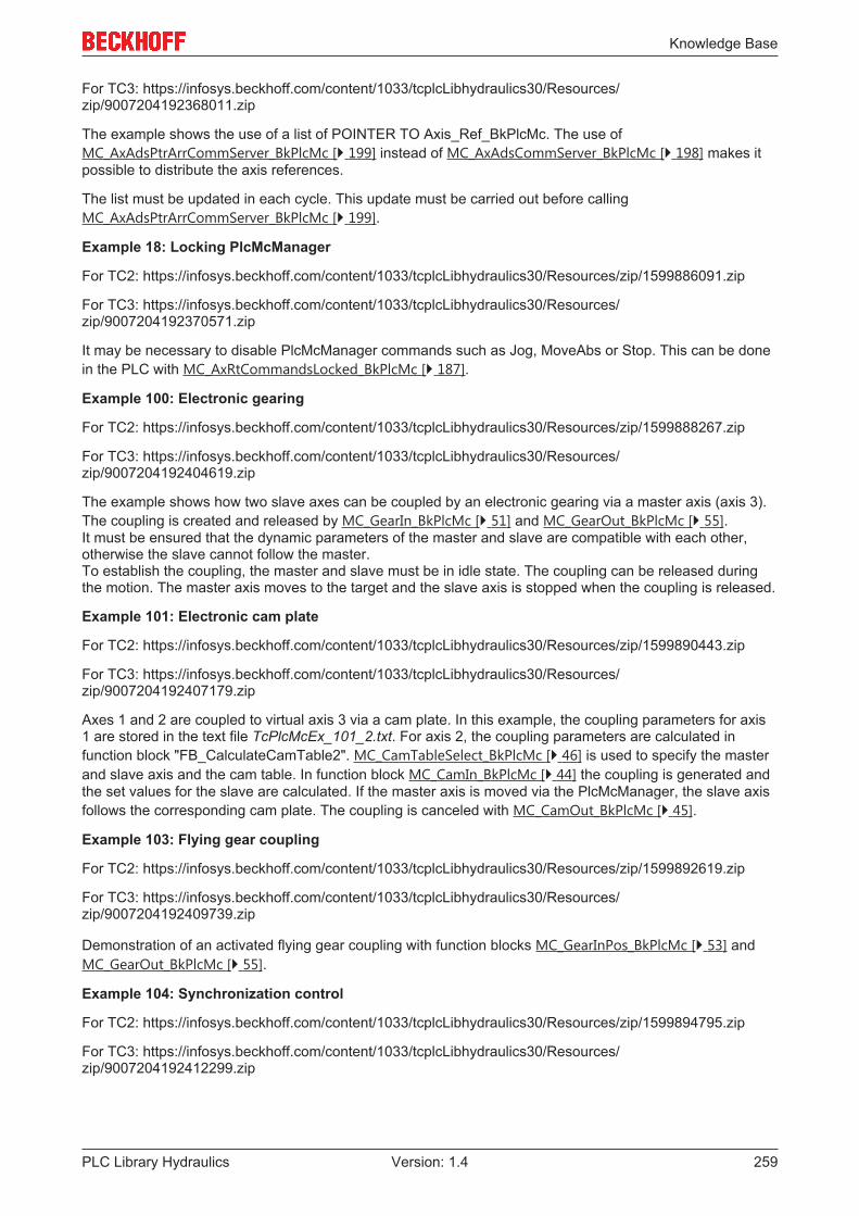
Knowledge Base
PLC Library Hydraulics 259Version: 1.4
For TC3: https://infosys.beckhoff.com/content/1033/tcplcLibhydraulics30/Resources/zip/9007204192368011.zip
The example shows the use of a list of POINTER TO Axis_Ref_BkPlcMc. The use ofMC_AxAdsPtrArrCommServer_BkPlcMc [} 199] instead of MC_AxAdsCommServer_BkPlcMc [} 198] makes itpossible to distribute the axis references.
The list must be updated in each cycle. This update must be carried out before callingMC_AxAdsPtrArrCommServer_BkPlcMc [} 199].
Example 18: Locking PlcMcManager
For TC2: https://infosys.beckhoff.com/content/1033/tcplcLibhydraulics30/Resources/zip/1599886091.zip
For TC3: https://infosys.beckhoff.com/content/1033/tcplcLibhydraulics30/Resources/zip/9007204192370571.zip
It may be necessary to disable PlcMcManager commands such as Jog, MoveAbs or Stop. This can be donein the PLC with MC_AxRtCommandsLocked_BkPlcMc [} 187].
Example 100: Electronic gearing
For TC2: https://infosys.beckhoff.com/content/1033/tcplcLibhydraulics30/Resources/zip/1599888267.zip
For TC3: https://infosys.beckhoff.com/content/1033/tcplcLibhydraulics30/Resources/zip/9007204192404619.zip
The example shows how two slave axes can be coupled by an electronic gearing via a master axis (axis 3).The coupling is created and released by MC_GearIn_BkPlcMc [} 51] and MC_GearOut_BkPlcMc [} 55].It must be ensured that the dynamic parameters of the master and slave are compatible with each other,otherwise the slave cannot follow the master.To establish the coupling, the master and slave must be in idle state. The coupling can be released duringthe motion. The master axis moves to the target and the slave axis is stopped when the coupling is released.
Example 101: Electronic cam plate
For TC2: https://infosys.beckhoff.com/content/1033/tcplcLibhydraulics30/Resources/zip/1599890443.zip
For TC3: https://infosys.beckhoff.com/content/1033/tcplcLibhydraulics30/Resources/zip/9007204192407179.zip
Axes 1 and 2 are coupled to virtual axis 3 via a cam plate. In this example, the coupling parameters for axis1 are stored in the text file TcPlcMcEx_101_2.txt. For axis 2, the coupling parameters are calculated infunction block "FB_CalculateCamTable2". MC_CamTableSelect_BkPlcMc [} 46] is used to specify the masterand slave axis and the cam table. In function block MC_CamIn_BkPlcMc [} 44] the coupling is generated andthe set values for the slave are calculated. If the master axis is moved via the PlcMcManager, the slave axisfollows the corresponding cam plate. The coupling is canceled with MC_CamOut_BkPlcMc [} 45].
Example 103: Flying gear coupling
For TC2: https://infosys.beckhoff.com/content/1033/tcplcLibhydraulics30/Resources/zip/1599892619.zip
For TC3: https://infosys.beckhoff.com/content/1033/tcplcLibhydraulics30/Resources/zip/9007204192409739.zip
Demonstration of an activated flying gear coupling with function blocks MC_GearInPos_BkPlcMc [} 53] andMC_GearOut_BkPlcMc [} 55].
Example 104: Synchronization control
For TC2: https://infosys.beckhoff.com/content/1033/tcplcLibhydraulics30/Resources/zip/1599894795.zip
For TC3: https://infosys.beckhoff.com/content/1033/tcplcLibhydraulics30/Resources/zip/9007204192412299.zip
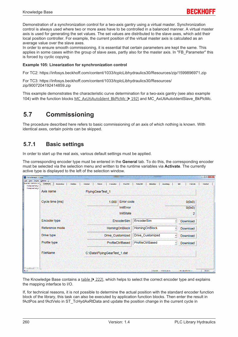
Knowledge Base
PLC Library Hydraulics260 Version: 1.4
Demonstration of a synchronization control for a two-axis gantry using a virtual master. Synchronizationcontrol is always used where two or more axes have to be controlled in a balanced manner. A virtual masteraxis is used for generating the set values. The set values are distributed to the slave axes, which add theirlocal position controller. For example, the current position of the virtual master axis is calculated as anaverage value over the slave axes.In order to ensure smooth commissioning, it is essential that certain parameters are kept the same. Thisapplies in some cases within the group of slave axes, partly also for the master axis. In "FB_Parameter" thisis forced by cyclic copying.
Example 105: Linearization for synchronization control
For TC2: https://infosys.beckhoff.com/content/1033/tcplcLibhydraulics30/Resources/zip/1599896971.zip
For TC3: https://infosys.beckhoff.com/content/1033/tcplcLibhydraulics30/Resources/zip/9007204192414859.zip
This example demonstrates the characteristic curve determination for a two-axis gantry (see also example104) with the function blocks MC_AxUtiAutoIdent_BkPlcMc [} 192] and MC_AxUtiAutoIdentSlave_BkPlcMc.
5.7 CommissioningThe procedure described here refers to basic commissioning of an axis of which nothing is known. Withidentical axes, certain points can be skipped.
5.7.1 Basic settingsIn order to start up the real axis, various default settings must be applied.
The corresponding encoder type must be entered in the General tab. To do this, the corresponding encodermust be selected via the selection menu and written to the runtime variables via Activate. The currentlyactive type is displayed to the left of the selection window.
The Knowledge Base contains a table [} 222], which helps to select the correct encoder type and explainsthe mapping interface to I/O.
If, for technical reasons, it is not possible to determine the actual position with the standard encoder functionblock of the library, this task can also be executed by application function blocks. Then enter the result infActPos and fActVelo in ST_TcHydAxRtData and update the position change in the current cycle in

Knowledge Base
PLC Library Hydraulics 261Version: 1.4
fActPosDelta. bEncoderResponse should be used to indicate whether the actual values could be updated.For the sake of uniformity use should again be made here of the fEnc_IncWeighting, fEnc_IncInterpolationand fEnc_ZeroShift or fEnc_RefShift parameters.
A range of devices and equipment might be functioning as actuators (Drivetyp), applying a variety of physicalprinciples to create a variable velocity that depends on an electrical magnitude. Depending on thecorresponding I/O component, the Drivetype must be set in the selection window and the variables must belinked to the field device. The Knowledge Base contains a table [} 225] which supports the selection of thetype to be set.
If the position measuring system is an incremental system, the corresponding referencing method [} 79]must also be defined.
On the Global tab you should initially enter 100 for the reference velocity. The value is corrected later, but inthis way, overlap etc. can be entered directly in %.
The acceleration and deceleration should be set to 100 mm/s². With this setting, this axis will accelerate toreference velocity in 1 s. The jog parameters should be set to 5 mm/s and 10 mm/s. The creep velocityshould be set to 5 mm/sec, the creep distance should be 10 mm and the braking distance 2 mm.
If the valve is covered and the valve data sheet is available, you can enter the overlap from the data sheeton the Valve tab.
On the Encoder tab, enter the resolution per increment in Inc. evaluation. Alternatively, an incrementnumber can also be specified in Inc. interpolation and the corresponding path in Inc. evaluation.
In the Controller tab, the lag and velocity controller must be set to zero.
For further commissioning, a Scope with the following variables should be recorded:
• SetVelo• ActVelo• SetPos• ActPos• fOutput• fLagCtrlOutput
If available, record pressures, forces and valve slide position.
If the controller enable and feed enable of the axis are set, the axis must not move. If this is the case, atemporary zero balance must be carried out.
5.7.2 Temporary zero compensationThe Offset compensation parameter is set in the Controller tab. Depending on the direction in which theaxis is drifting, a value between -10 V and +10 V must be entered. As a rule, values of +/- 0.5 V are to beexpected.
5.7.3 Movement directionsThe jog button should be used to move the axis slowly. If this is not the case, the pressure supply must bechecked. Furthermore, switching valves may also have to be operated or the compensation of the valveoverlap is set too small.
It is recommended to specify a positive direction of movement for the axis that corresponds to the way themachine works. If the axis moves in this direction, the actual position should count upwards. If this is not thecase, the counting direction can be inverted on the Encoder tab. If the direction of change of the indicatedposition corresponds to the mechanical movement, but the direction of action of the given commands is notas desired, the output can be inverted on the Valve tab.

Knowledge Base
PLC Library Hydraulics262 Version: 1.4
NOTE! When the valve output is inverted, the offset compensation must be adjusted, as it is notinverted and its effect is reversed.
5.7.4 Position measuring systemThe axis should show a plausible actual position for both an absolute and an incremental position measuringsystem. The zero point of the encoder and the defined zero point of the axis usually do not coincide. On theEncoder tab, you can enter the desired current position and transfer it to the axis via the Set-Pos button. Atthis point in time, this set position does not have to match the actual position exactly. Especially withincremental measuring systems, homing is carried out later on.
The PlcMcManager adapts the display of the parameters as far as possible to the set encoder type. As aresult, different parameters can be visible for different axes.
For incremental encoder types, the diagram shown above appears. The visibility of the parameters forhoming depends on the set homing method.
To avoid collisions during commissioning, the software limit switches should be activated and setappropriately in the Monitor tab. Since the actual position can differ slightly from the actual position, it isrecommended to set the software limit switches a little closer.
5.7.5 Characteristic curve measurementThe characteristic curve measurement (MC_AxUtiAutoIdent_BkPlcMc) not only determines the characteristiccurve itself, but also the reference velocity, the velocity ratio and the optional travel distance limits. For moreinformation on the setting options, see the function block itself.
The reference velocity should be preset to an approximate plausible value. One possibility is to calculate thesmaller cylinder area (A [mm²]) with the nominal volume flow (Qn [l/min)] of the valve:
Knowledge Base
PLC Library Hydraulics 263Version: 1.4
Vref:= Qn*1.000.000/60/ A
The LinDef tab can be used to implement various settings. Further information can be found here.
If this is activated, the AutoIdent function block starts by first determining the travel limits. The axis is thenpositioned at a distance of at least 10 % from the travel limits, in order to determine the overlap. Once thishas been carried out successfully, the axis moves to the lower end and starts measuring. Depending on theavailable travel distance, several measurements are carried out in each direction.
Once the characteristic curve has been successfully measured, it can be viewed in the LinTab tab. Asuccessfully measured characteristic curve can be recognized by the fact that stParams.bLinTabAvaiable isTRUE.
The chapter Coverage and reference velocity should be skipped if the characteristic curve was measuredsuccessfully.
5.7.6 OverlapIn order to determine the overlap, the set velocity must be increased slowly until a response by the actualvelocity can be recognized. It is possible that the set velocity must be increased to a value of up to 30 mm/sbefore a response of the actual velocity can be seen. When measuring the overlap, the overlap itself shouldalways be set to zero.
If different velocity set values are required in order to move the axis in positive or negative direction fromstandstill, this indicates an asymmetric valve. In this case the check mark Asym in the Global tab must beset and activated. The valve can now be parameterized separately in positive and negative direction.
The set velocity at which the axis moves must be entered under Overlap in the "Valve" tab. If the overlap hasalready been assigned a value, this value must be taken into account. For asymmetric valves ensure that theentry is made in the correct field; the overlap for the positive direction is expected in the upper field, theoverlap for the negative direction in the lower field.
After this optimization the axis should also respond at different small velocities. Whether the axis respondswith the right velocity is not important.
If an overlap has been entered from the data sheet and the axis always moves too fast, the overlap shouldbe reduced.
5.7.7 Reference velocity/velocity ratioNOTE! This chapter describes manual commissioning. A characteristic curve measurement also
determines the parameters discussed here. If it is used, this chapter should be skipped.
Once the axis can be moved at low velocity, the reference velocity must be set.
In order to determine the reference velocity, the set velocity is increased step-by-step, and a check is carriedout to determine whether the axis follows with approximately the set velocity.
NOTE! In this step, only movements in the faster direction are to be evaluated. The oil istransported into the small piston surface! The next step deals with directional dependency.
To trigger the required movements, the position and velocity can be specified in the Status tab. Themovement is executed with the Start button. The previously created Scope View should be used to analyzethe velocities.
NOTE! The software limit switches should be activated and set so that the axis does not hit themechanical limit stops.

Knowledge Base
PLC Library Hydraulics264 Version: 1.4
If the actual velocity is much lower than the set velocity, the reference velocity should be reduced.
If the actual velocity is much higher than the set velocity, the reference velocity should be increased.
The appropriate reference velocity has been found when the medium to high set and actual velocities almostmatch.
NOTE! The reference velocity does not have to correspond to the actual or calculated maximumvelocity of the axis.
The following diagram shows the linearization section-by-section through overlapping and reference velocitywith a non-linear characteristic curve. It is left to the user to decide where the maximum deviation betweenthe linearization and the actual characteristic curve can occur.

Knowledge Base
PLC Library Hydraulics 265Version: 1.4
The usual asymmetry of the cylinders causes the axis to move too slowly in the slower direction at anycommanded velocity when the reference velocity is set. This behavior can be compensated for on the Valvetab by using the velocity ratio parameter.
When the behavior is symmetrical, this parameter should be set to 1,000. If the positive direction of travel isthe slower direction, use a value greater than 1,000. If the negative direction of travel is the slower direction,a value less than 1,000 should be used. This increases the output in the slower direction and compensatesfor the asymmetry.
NOTE! With this compensation, the output can only be increased up to its maximum value. Theparameterization must be carried out at velocities that the axis can reach in both directions.
NOTE! If the parameter is changed in the wrong direction, the velocity decreases in the fasterdirection. In this case the reference velocity must not be corrected.
5.7.8 ReferencingFor incremental position measuring systems: Now at the latest, the axis should be referenced correctly andfully. Enter the index velocity, index direction, sync velocity, sync direction and the reference position underthe Encoder tab. For more information see MC_Home_BkPlcMc [} 57].
NOTE! It may be necessary to reset the travel limits.
5.7.9 Dynamics/target approachAt this point in time, the axis is able to position with different velocities and moderate dynamics.
On the Monitor tab you can set when the axis should report ready. An axis is in the target if the remainingdistance is smaller than PosRange and BrakeDistance; for the TargetFilterTime the remaining distance mustbe smaller than Targetrange. These three parameters must be set appropriately according to the applicationrequirements.
The user subsequently has to decide whether the axis should be positioned time-based or displacement-based.
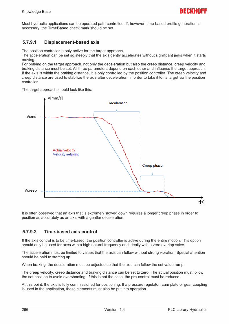
Knowledge Base
PLC Library Hydraulics266 Version: 1.4
Most hydraulic applications can be operated path-controlled. If, however, time-based profile generation isnecessary, the TimeBased check mark should be set.
5.7.9.1 Displacement-based axis
The position controller is only active for the target approach. The acceleration can be set so steeply that the axis gently accelerates without significant jerks when it startsmoving. For braking on the target approach, not only the deceleration but also the creep distance, creep velocity andbraking distance must be set. All three parameters depend on each other and influence the target approach.If the axis is within the braking distance, it is only controlled by the position controller. The creep velocity andcreep distance are used to stabilize the axis after deceleration, in order to take it to its target via the positioncontroller.
The target approach should look like this:
It is often observed that an axis that is extremely slowed down requires a longer creep phase in order toposition as accurately as an axis with a gentler deceleration.
5.7.9.2 Time-based axis control
If the axis control is to be time-based, the position controller is active during the entire motion. This optionshould only be used for axes with a high natural frequency and ideally with a zero overlap valve.
The acceleration must be limited to values that the axis can follow without strong vibration. Special attentionshould be paid to starting up.
When braking, the deceleration must be adjusted so that the axis can follow the set value ramp.
The creep velocity, creep distance and braking distance can be set to zero. The actual position must followthe set position to avoid overshooting. If this is not the case, the pre-control must be reduced.
At this point, the axis is fully commissioned for positioning. If a pressure regulator, cam plate or gear couplingis used in the application, these elements must also be put into operation.

Appendix
PLC Library Hydraulics 267Version: 1.4
6 Appendix
6.1 Support and ServiceBeckhoff and their partners around the world offer comprehensive support and service, making available fastand competent assistance with all questions related to Beckhoff products and system solutions.
Beckhoff's branch offices and representatives
Please contact your Beckhoff branch office or representative for local support and service on Beckhoffproducts!
The addresses of Beckhoff's branch offices and representatives round the world can be found on her internetpages:http://www.beckhoff.com
You will also find further documentation for Beckhoff components there.
Beckhoff Headquarters
Beckhoff Automation GmbH & Co. KG
Huelshorstweg 2033415 VerlGermany
Phone: +49(0)5246/963-0Fax: +49(0)5246/963-198e-mail: [email protected]
Beckhoff Support
Support offers you comprehensive technical assistance, helping you not only with the application ofindividual Beckhoff products, but also with other, wide-ranging services:
• support• design, programming and commissioning of complex automation systems• and extensive training program for Beckhoff system components
Hotline: +49(0)5246/963-157Fax: +49(0)5246/963-9157e-mail: [email protected]
Beckhoff Service
The Beckhoff Service Center supports you in all matters of after-sales service:
• on-site service• repair service• spare parts service• hotline service
Hotline: +49(0)5246/963-460Fax: +49(0)5246/963-479e-mail: [email protected]