manual on uniform traffic ontrol raffic control devices · section 4d.13 preemption and priority...
TRANSCRIPT

U.S. Department of Transportation
Federal Highway Administration
Manual on UniformTraffic Control Devices
for Streets and Highways
Manual on UniformTraffic Control Devices
for Streets and Highways
Part 4Highway Traffic Signals


2003 Edition Page TC4-1
PART 4. HIGHWAY TRAFFIC SIGNALS
TABLE OF CONTENTS
Page
CHAPTER 4A. GENERAL
Section 4A.01 Types........................................................................................................................................4A-1Section 4A.02 Definitions Relating to Highway Traffic Signals ....................................................................4A-1
CHAPTER 4B. TRAFFIC CONTROL SIGNALS—GENERAL
Section 4B.01 General.....................................................................................................................................4B-1Section 4B.02 Basis of Installation or Removal of Traffic Control Signals...................................................4B-1Section 4B.03 Advantages and Disadvantages of Traffic Control Signals .....................................................4B-1Section 4B.04 Alternatives to Traffic Control Signals....................................................................................4B-2Section 4B.05 Adequate Roadway Capacity...................................................................................................4B-2
CHAPTER 4C. TRAFFIC CONTROL SIGNAL NEEDS STUDIES
Section 4C.01 Studies and Factors for Justifying Traffic Control Signals .....................................................4C-1Section 4C.02 Warrant 1, Eight-Hour Vehicular Volume................................................................................4C-2Section 4C.03 Warrant 2, Four-Hour Vehicular Volume.................................................................................4C-4Section 4C.04 Warrant 3, Peak Hour ..............................................................................................................4C-4Section 4C.05 Warrant 4, Pedestrian Volume .................................................................................................4C-6Section 4C.06 Warrant 5, School Crossing.....................................................................................................4C-6Section 4C.07 Warrant 6, Coordinated Signal System ...................................................................................4C-8Section 4C.08 Warrant 7, Crash Experience ...................................................................................................4C-8Section 4C.09 Warrant 8, Roadway Network .................................................................................................4C-9
CHAPTER 4D. TRAFFIC CONTROL SIGNAL FEATURES
Section 4D.01 General ....................................................................................................................................4D-1Section 4D.02 Responsibility for Operation and Maintenance.......................................................................4D-1Section 4D.03 Provisions for Pedestrians .......................................................................................................4D-2Section 4D.04 Meaning of Vehicular Signal Indications ................................................................................4D-2Section 4D.05 Application of Steady Signal Indications................................................................................4D-3Section 4D.06 Application of Steady Signal Indications for Left Turns ........................................................4D-5Section 4D.07 Application of Steady Signal Indications for Right Turns......................................................4D-7Section 4D.08 Prohibited Steady Signal Indications ......................................................................................4D-8Section 4D.09 Unexpected Conflicts During Green or Yellow Intervals........................................................4D-8Section 4D.10 Yellow Change and Red Clearance Intervals ..........................................................................4D-8Section 4D.11 Application of Flashing Signal Indications.............................................................................4D-9Section 4D.12 Flashing Operation of Traffic Control Signals........................................................................4D-9Section 4D.13 Preemption and Priority Control of Traffic Control Signals.................................................4D-10Section 4D.14 Coordination of Traffic Control Signals................................................................................4D-12Section 4D.15 Size, Number, and Location of Signal Faces by Approach ..................................................4D-12Section 4D.16 Number and Arrangement of Signal Sections in Vehicular Traffic Control Signal Faces .....4D-16Section 4D.17 Visibility, Shielding, and Positioning of Signal Faces ..........................................................4D-17Section 4D.18 Design, Illumination, and Color of Signal Sections .............................................................4D-19Section 4D.19 Lateral Placement of Signal Supports and Cabinets .............................................................4D-20Section 4D.20 Temporary Traffic Control Signals........................................................................................4D-20Section 4D.21 Traffic Signal Signs, Auxiliary..............................................................................................4D-21
Page TC4-2 2003 Edition
CHAPTER 4E. PEDESTRIAN CONTROL FEATURES
Section 4E.01 Pedestrian Signal Heads ..........................................................................................................4E-1Section 4E.02 Meaning of Pedestrian Signal Head Indications .....................................................................4E-1Section 4E.03 Application of Pedestrian Signal Heads ..................................................................................4E-1Section 4E.04 Size, Design, and Illumination of Pedestrian Signal Head Indications...................................4E-1Section 4E.05 Location and Height of Pedestrian Signal Heads....................................................................4E-3Section 4E.06 Accessible Pedestrian Signals..................................................................................................4E-3Section 4E.07 Countdown Pedestrian Signals ................................................................................................4E-5Section 4E.08 Pedestrian Detectors ................................................................................................................4E-6Section 4E.09 Accessible Pedestrian Signal Detectors...................................................................................4E-6Section 4E.10 Pedestrian Intervals and Signal Phases....................................................................................4E-7
CHAPTER 4F. TRAFFIC CONTROL SIGNALS FOR EMERGENCY VEHICLE ACCESS
Section 4F.01 Applications of Emergency-Vehicle Traffic Control Signals ..................................................4F-1Section 4F.02 Design of Emergency-Vehicle Traffic Control Signals ...........................................................4F-1Section 4F.03 Operation of Emergency-Vehicle Traffic Control Signals.......................................................4F-1
CHAPTER 4G. TRAFFIC CONTROL SIGNALS FOR ONE-LANE, TWO-WAY FACILITIES
Section 4G.01 Application of Traffic Control Signals for One-Lane, Two-Way Facilities............................4G-1Section 4G.02 Design of Traffic Control Signals for One-Lane, Two-Way Facilities ...................................4G-1Section 4G.03 Operation of Traffic Control Signals for One-Lane, Two-Way Facilities...............................4G-1
CHAPTER 4H. TRAFFIC CONTROL SIGNALS FOR FREEWAY ENTRANCE RAMPS
Section 4H.01 Application of Freeway Entrance Ramp Control Signals .......................................................4H-1Section 4H.02 Design of Freeway Entrance Ramp Control Signals ..............................................................4H-1
CHAPTER 4I. TRAFFIC CONTROL FOR MOVABLE BRIDGES
Section 4I.01 Application of Traffic Control for Movable Bridges................................................................4I-1Section 4I.02 Design and Location of Movable Bridge Signals and Gates....................................................4I-1Section 4I.03 Operation of Movable Bridge Signals and Gates .....................................................................4I-2
CHAPTER 4J. LANE-USE CONTROL SIGNALS
Section 4J.01 Application of Lane-Use Control Signals ................................................................................4J-1Section 4J.02 Meaning of Lane-Use Control Signal Indications....................................................................4J-1Section 4J.03 Design of Lane-Use Control Signals........................................................................................4J-2Section 4J.04 Operation of Lane-Use Control Signals ...................................................................................4J-3
CHAPTER 4K. FLASHING BEACONS
Section 4K.01 General Design and Operation of Flashing Beacons ..............................................................4K-1Section 4K.02 Intersection Control Beacon....................................................................................................4K-1Section 4K.03 Warning Beacon ......................................................................................................................4K-1Section 4K.04 Speed Limit Sign Beacon........................................................................................................4K-2Section 4K.05 Stop Beacon.............................................................................................................................4K-2
CHAPTER 4L. IN-ROADWAY LIGHTS
Section 4L.01 Application of In-Roadway Lights ..........................................................................................4L-1Section 4L.02 In-Roadway Warning Lights at Crosswalks ............................................................................4L-1
2003 Edition Page TC4-3
FIGURES
CHAPTER 4C. TRAFFIC CONTROL SIGNAL NEEDS STUDIES
Figure 4C-1 Warrant 2, Four-Hour Vehicular Volume.................................................................................4C-5Figure 4C-2 Warrant 2, Four-Hour Vehicular Volume (70% Factor)...........................................................4C-5Figure 4C-3 Warrant 3, Peak Hour ..............................................................................................................4C-7Figure 4C-4 Warrant 3, Peak Hour (70% Factor) ........................................................................................4C-7
CHAPTER 4D. TRAFFIC CONTROL SIGNAL FEATURES
Figure 4D-1 Maximum Mounting Height of Signal Faces Located Between 12 Meters (4 Feet) and 16 Meters (53 Feet) from Stop Line .....................................................................................4D-14
Figure 4D-2 Horizontal Location of Signal Faces.....................................................................................4D-15Figure 4D-3 Typical Arrangements of Signal Lenses in Signal Faces ......................................................4D-18
CHAPTER 4E. PEDESTRIAN CONTROL FEATURES
Figure 4E-1 Typical Pedestrian Signal Indications......................................................................................4E-2Figure 4E-2 Recommended Pushbutton Locations for Accessible Pedestrian Signals ...............................4E-8
CHAPTER 4J. LANE-USE CONTROL SIGNALS
Figure 4J-1 Left-Turn Lane-Use Control Signals ........................................................................................4J-2
TABLES
CHAPTER 4C. TRAFFIC CONTROL SIGNAL NEEDS STUDIES
Table 4C-1 Warrant 1, Eight-Hour Vehicular Volume................................................................................4C-3
CHAPTER 4D. TRAFFIC CONTROL SIGNAL FEATURES
Table 4D-1 Minimum Sight Distance ......................................................................................................4D-13

2003 Edition Page 4A-1
Sect. 4A.01 to 4A.02
CHAPTER 4A. GENERAL
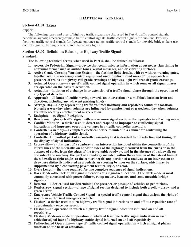
Section 4A.01 TypesSupport:
The following types and uses of highway traffic signals are discussed in Part 4: traffic control signals;pedestrian signals; emergency-vehicle traffic control signals; traffic control signals for one-lane, two-wayfacilities; traffic control signals for freeway entrance ramps; traffic control signals for movable bridges; lane-usecontrol signals; flashing beacons; and in-roadway lights.
Section 4A.02 Definitions Relating to Highway Traffic SignalsStandard:
The following technical terms, when used in Part 4, shall be defined as follows:1. Accessible Pedestrian Signal—a device that communicates information about pedestrian timing in
nonvisual format such as audible tones, verbal messages, and/or vibrating surfaces.2. Active Grade Crossing Warning System—the flashing-light signals, with or without warning gates,
together with the necessary control equipment used to inform road users of the approach orpresence of trains at highway-rail grade crossings or highway-light rail transit grade crossings.
3. Actuated Operation—a type of traffic control signal operation in which some or all signal phasesare operated on the basis of actuation.
4. Actuation—initiation of a change in or extension of a traffic signal phase through the operation ofany type of detector.
5. Approach—all lanes of traffic moving towards an intersection or a midblock location from onedirection, including any adjacent parking lane(s).
6. Average Day—a day representing traffic volumes normally and repeatedly found at a location,typically a weekday when volumes are influenced by employment or a weekend day when volumesare influenced by entertainment or recreation.
7. Backplate—see Signal Backplate. 8. Beacon—a highway traffic signal with one or more signal sections that operates in a flashing mode.9. Conflict Monitor—a device used to detect and respond to improper or conflicting signal
indications and improper operating voltages in a traffic controller assembly.10. Controller Assembly—a complete electrical device mounted in a cabinet for controlling the
operation of a highway traffic signal.11. Controller Unit—that part of a controller assembly that is devoted to the selection and timing of
the display of signal indications.12. Crosswalk—(a) that part of a roadway at an intersection included within the connections of the
lateral lines of the sidewalks on opposite sides of the highway measured from the curbs or in theabsence of curbs, from the edges of the traversable roadway, and in the absence of a sidewalk onone side of the roadway, the part of a roadway included within the extension of the lateral lines ofthe sidewalk at right angles to the centerline; (b) any portion of a roadway at an intersection orelsewhere distinctly indicated as a pedestrian crossing by lines on the surface, which may besupplemented by a contrasting pavement texture, style, or color.
13. Cycle Length—the time required for one complete sequence of signal indications.14. Dark Mode—the lack of all signal indications at a signalized location. (The dark mode is most
commonly associated with power failures, ramp meters, beacons, and some movable bridgesignals.)
15. Detector—a device used for determining the presence or passage of vehicles or pedestrians.16. Dual-Arrow Signal Section—a type of signal section designed to include both a yellow arrow and a
green arrow.17. Emergency Vehicle Traffic Control Signal—a special traffic control signal that assigns the right-of-
way to an authorized emergency vehicle.18. Flasher—a device used to turn highway traffic signal indications on and off at a repetitive rate of
approximately once per second.19. Flashing—an operation in which a highway traffic signal indication is turned on and off
repetitively.20. Flashing Mode—a mode of operation in which at least one traffic signal indication in each
vehicular signal face of a highway traffic signal is turned on and off repetitively.21. Full-Actuated Operation—a type of traffic control signal operation in which all signal phases
function on the basis of actuation.

Page 4A-2 2003 Edition
Sect. 4A.02
22. Highway Traffic Signal—a power-operated traffic control device by which traffic is warned ordirected to take some specific action. These devices do not include signals at toll plazas, power-operated signs, illuminated pavement markers, warning lights (see Section 6F.78), or steady-burning electric lamps.
23. In-Roadway Lights—a special type of highway traffic signal installed in the roadway surface towarn road users that they are approaching a condition on or adjacent to the roadway that mightnot be readily apparent and might require the road users to slow down and/or come to a stop.
24. Intersection—(a) the area embraced within the prolongation or connection of the lateral curb lines,or if none, the lateral boundary lines of the roadways of two highways that join one another at, orapproximately at, right angles, or the area within which vehicles traveling on different highwaysthat join at any other angle might come into conflict; (b) the junction of an alley or driveway witha roadway or highway shall not constitute an intersection.
25. Intersection Control Beacon—a beacon used only at an intersection to control two or moredirections of travel.
26. Interval—the part of a signal cycle during which signal indications do not change.27. Interval Sequence—the order of appearance of signal indications during successive intervals of a
signal cycle.28. Lane-Use Control Signal—a signal face displaying signal indications to permit or prohibit the use
of specific lanes of a roadway or to indicate the impending prohibition of such use.29. Lens—see Signal Lens.30. Louver—see Signal Louver.31. Major Street—the street normally carrying the higher volume of vehicular traffic.32. Malfunction Management Unit—same as Conflict Monitor.33. Minor Street—the street normally carrying the lower volume of vehicular traffic.34. Movable Bridge Resistance Gate—a type of traffic gate, which is located downstream of the
movable bridge warning gate, that provides a physical deterrent to vehicle and/or pedestriantraffic when placed in the appropriate position.
35. Movable Bridge Signal—a highway traffic signal installed at a movable bridge to notify traffic tostop during periods when the roadway is closed to allow the bridge to open.
36. Movable Bridge Warning Gate—a type of traffic gate designed to warn, but not primarily to block,vehicle and/or pedestrian traffic when placed in the appropriate position.
37. Pedestrian Change Interval—an interval during which the flashing UPRAISED HAND(symbolizing DONT WALK) signal indication is displayed. When a verbal message is provided atan accessible pedestrian signal, the verbal message is “wait.”
38. Pedestrian Clearance Time—the time provided for a pedestrian crossing in a crosswalk, afterleaving the curb or shoulder, to travel to the far side of the traveled way or to a median.
39. Pedestrian Signal Head—a signal head, which contains the symbols WALKING PERSON(symbolizing WALK) and UPRAISED HAND (symbolizing DONT WALK), that is installed todirect pedestrian traffic at a traffic control signal.
40. Permissive Mode—a mode of traffic control signal operation in which, when a CIRCULARGREEN signal indication is displayed, left or right turns are permitted to be made after yielding topedestrians and/or oncoming traffic.
41. Platoon—a group of vehicles or pedestrians traveling together as a group, either voluntarily orinvoluntarily, because of traffic signal controls, geometrics, or other factors.
42. Preemption Control—the transfer of normal operation of a traffic control signal to a specialcontrol mode of operation.
43. Pretimed Operation—a type of traffic control signal operation in which none of the signal phasesfunction on the basis of actuation.
44. Priority Control—a means by which the assignment of right-of-way is obtained or modified.45. Protected Mode—a mode of traffic control signal operation in which left or right turns are
permitted to be made when a left or right GREEN ARROW signal indication is displayed.46. Pushbutton—a button to activate pedestrian timing.47. Pushbutton Locator Tone—a repeating sound that informs approaching pedestrians that they are
required to push a button to actuate pedestrian timing and that enables pedestrians who havevisual disabilities to locate the pushbutton.
48. Ramp Control Signal—a highway traffic signal installed to control the flow of traffic onto afreeway at an entrance ramp or at a freeway-to-freeway ramp connection.
49. Ramp Meter—see Ramp Control Signal.50. Red Clearance Interval—an optional interval that follows a yellow change interval and precedes
the next conflicting green interval.

51. Right-of-Way (Assignment)—the permitting of vehicles and/or pedestrians to proceed in a lawfulmanner in preference to other vehicles or pedestrians by the display of signal indications.
52. Roadway Network—a geographical arrangement of intersecting roadways.53. Semiactuated Operation—a type of traffic control signal operation in which at least one, but not
all, signal phases function on the basis of actuation.54. Separate Left-Turn Signal Face—a signal face for controlling a left-turn movement that sometimes
displays a different color of circular signal indication than the adjacent through signal facesdisplay.
55. Shared Left-Turn Signal Face—a signal face, for controlling both a left turn movement and theadjacent through movement, that always displays the same color of circular signal indication thatthe adjacent through signal face or faces display.
56. Signal Backplate—a thin strip of material that extends outward from and parallel to a signal faceon all sides of a signal housing to provide a background for improved visibility of the signalindications.
57. Signal Coordination—the establishment of timed relationships between adjacent traffic controlsignals.
58. Signal Face—that part of a traffic control signal provided for controlling one or more trafficmovements on a single approach.
59. Signal Head—an assembly of one or more signal sections.60. Signal Housing—that part of a signal section that protects the light source and other required
components.61. Signal Indication—the illumination of a signal lens or equivalent device.62. Signal Lens—that part of the signal section that redirects the light coming directly from the light
source and its reflector, if any.63. Signal Louver—a device that can be mounted inside a signal visor to restrict visibility of a signal
indication from the side or to limit the visibility of the signal indication to a certain lane or lanes,or to a certain distance from the stop line.
64. Signal Phase—the right-of-way, yellow change, and red clearance intervals in a cycle that areassigned to an independent traffic movement or combination of movements.
65. Signal Section—the assembly of a signal housing, signal lens, and light source with necessarycomponents to be used for providing one signal indication.
66. Signal System—two or more traffic control signals operating in signal coordination.67. Signal Timing—the amount of time allocated for the display of a signal indication.68. Signal Visor—that part of a signal section that directs the signal indication specifically to
approaching traffic and reduces the effect of direct external light entering the signal lens.69. Signal Warrant—a threshold condition that, if found to be satisfied as part of an engineering study,
shall result in analysis of other traffic conditions or factors to determine whether a traffic controlsignal or other improvement is justified.
70. Speed Limit Sign Beacon—a beacon used to supplement a SPEED LIMIT sign.71. Steady (Steady Mode)—the continuous illumination of a signal indication for the duration of an
interval, signal phase, or consecutive signal phases.72. Stop Beacon—a beacon used to supplement a STOP sign, a DO NOT ENTER sign, or a WRONG
WAY sign.73. Traffic Control Signal (Traffic Signal)—any highway traffic signal by which traffic is alternately
directed to stop and permitted to proceed.74. Vibrotactile Pedestrian Device—a device that communicates, by touch, information about
pedestrian timing using a vibrating surface.75. Visibility-Limited Signal Face or Signal Section—a type of signal face or signal section designed
(or shielded, hooded, or louvered) to restrict the visibility of a signal indication from the side, to acertain lane or lanes, or to a certain distance from the stop line.
76. Walk Interval—an interval during which the WALKING PERSON (symbolizing WALK) signalindication is displayed. When a verbal message is provided at an accessible pedestrian signal, theverbal message is “walk sign.”
77. Warning Beacon—a beacon used only to supplement an appropriate warning or regulatory sign ormarker.
78. Yellow Change Interval—the first interval following the green interval during which the yellowsignal indication is displayed.
2003 Edition Page 4A-3
Sect. 4A.02


2003 Edition Page 4B-1
Sect. 4B.01 to 4B.03
CHAPTER 4B. TRAFFIC CONTROL SIGNALS—GENERAL
Section 4B.01 GeneralStandard:
A traffic control signal (traffic signal) shall be defined as any highway traffic signal by which traffic isalternately directed to stop and permitted to proceed.
Traffic shall be defined as pedestrians, bicyclists, ridden or herded animals, vehicles, streetcars, andother conveyances either singularly or together while using any highway for purposes of travel.Support:
Words such as pedestrians and bicyclists are used redundantly in selected sections of Part 4 to encouragesensitivity to these elements of “traffic.”
Standards for traffic control signals are important because traffic control signals need to attract the attentionof a variety of road users, including those who are older, those with impaired vision, as well as those who arefatigued or distracted, or who are not expecting to encounter a signal at a particular location.
Section 4B.02 Basis of Installation or Removal of Traffic Control SignalsGuidance:
The selection and use of traffic control signals should be based on an engineering study of roadway, traffic,and other conditions.Support:
A careful analysis of traffic operations, pedestrian and bicyclist needs, and other factors at a large number ofsignalized and unsignalized locations, coupled with engineering judgment, has provided a series of signalwarrants, described in Chapter 4C, that define the minimum conditions under which installing traffic controlsignals might be justified.Guidance:
Engineering judgment should be applied in the review of operating traffic control signals to determinewhether the type of installation and the timing program meet the current requirements of all forms of traffic.
If changes in traffic patterns eliminate the need for a traffic control signal, consideration should be given toremoving it and replacing it with appropriate alternative traffic control devices, if any are needed.Option:
If the engineering study indicates that the traffic control signal is no longer justified, removal may beaccomplished using the following steps:
A. Determine the appropriate traffic control to be used after removal of the signal.B. Remove any sight-distance restrictions as necessary.C. Inform the public of the removal study, for example by installing an informational sign (or signs) with
the legend TRAFFIC SIGNAL UNDER STUDY FOR REMOVAL at the signalized location in a positionwhere it is visible to all road users.
D. Flash or cover the signal heads for a minimum of 90 days, and install the appropriate stop control orother traffic control devices.
E. Remove the signal if the engineering data collected during the removal study period confirms that thesignal is no longer needed. Instead of total removal of the traffic control signal, the poles and cablesmay remain in place after removal of the signal heads for continued analysis.
Section 4B.03 Advantages and Disadvantages of Traffic Control SignalsSupport:
When properly used, traffic control signals are valuable devices for the control of vehicular and pedestriantraffic. They assign the right-of-way to the various traffic movements and thereby profoundly influence trafficflow.
Traffic control signals that are properly designed, located, operated, and maintained will have one or more ofthe following advantages:
A. They provide for the orderly movement of traffic.B. They increase the traffic-handling capacity of the intersection if:
1. Proper physical layouts and control measures are used, and 2. The signal operational parameters are reviewed and updated (if needed) on a regular basis (as
engineering judgment determines that significant traffic flow and/or land use changes have occurred)

Page 4B-2 2003 Edition
Sect. 4B.03 to 4B.05
to maximize the ability of the traffic control signal to satisfy current traffic demands.C. They reduce the frequency and severity of certain types of crashes, especially right-angle collisions.D. They are coordinated to provide for continuous or nearly continuous movement of traffic at a definite
speed along a given route under favorable conditions.E. They are used to interrupt heavy traffic at intervals to permit other traffic, vehicular or pedestrian, to
cross.Traffic control signals are often considered a panacea for all traffic problems at intersections. This belief has
led to traffic control signals being installed at many locations where they are not needed, adversely affecting thesafety and efficiency of vehicular, bicycle, and pedestrian traffic.
Traffic control signals, even when justified by traffic and roadway conditions, can be ill-designed,ineffectively placed, improperly operated, or poorly maintained. Improper or unjustified traffic control signalscan result in one or more of the following disadvantages:
A. Excessive delay;B. Excessive disobedience of the signal indications;C. Increased use of less adequate routes as road users attempt to avoid the traffic control signals; andD. Significant increases in the frequency of collisions (especially rear-end collisions).
Section 4B.04 Alternatives to Traffic Control SignalsGuidance:
Since vehicular delay and the frequency of some types of crashes are sometimes greater under traffic signalcontrol than under STOP sign control, consideration should be given to providing alternatives to traffic controlsignals even if one or more of the signal warrants has been satisfied.Option:
These alternatives may include, but are not limited to, the following:A. Installing signs along the major street to warn road users approaching the intersection;B. Relocating the stop line(s) and making other changes to improve the sight distance at the intersection;C. Installing measures designed to reduce speeds on the approaches;D. Installing a flashing beacon at the intersection to supplement STOP sign control;E. Installing flashing beacons on warning signs in advance of a STOP sign controlled intersection on major-
and/or minor-street approaches;F. Adding one or more lanes on a minor-street approach to reduce the number of vehicles per lane on the
approach;G. Revising the geometrics at the intersection to channelize vehicular movements and reduce the time
required for a vehicle to complete a movement, which could also assist pedestrians;H. Installing roadway lighting if a disproportionate number of crashes occur at night;I. Restricting one or more turning movements, perhaps on a time-of-day basis, if alternate routes are
available;J. If the warrant is satisfied, installing multiway STOP sign control;K. Installing a roundabout intersection; andL. Employing other alternatives, depending on conditions at the intersection.
Section 4B.05 Adequate Roadway CapacitySupport:
The delays inherent in the alternating assignment of right-of-way at intersections controlled by traffic controlsignals can frequently be reduced by widening the major roadway, the minor roadway, or both roadways.Widening the minor roadway often benefits the operations on the major roadway, because it reduces the greentime that must be assigned to minor-roadway traffic. In urban areas, the effect of widening can be achieved byeliminating parking on intersection approaches. It is desirable to have at least two lanes for moving traffic oneach approach to a signalized location. Additional width on the departure side of the intersection, as well as onthe approach side, will sometimes be needed to clear traffic through the intersection effectively.Guidance:
Adequate roadway capacity should be provided at a signalized location. Before an intersection is widened,the additional green time pedestrians need to cross the widened roadways should be considered to determine if itwill exceed the green time saved through improved vehicular flow.

2003 Edition Page 4C-1
Sect. 4C.01
CHAPTER 4C. TRAFFIC CONTROL SIGNAL NEEDS STUDIES
Section 4C.01 Studies and Factors for Justifying Traffic Control SignalsStandard:
An engineering study of traffic conditions, pedestrian characteristics, and physical characteristics ofthe location shall be performed to determine whether installation of a traffic control signal is justified at aparticular location.
The investigation of the need for a traffic control signal shall include an analysis of the applicablefactors contained in the following traffic signal warrants and other factors related to existing operationand safety at the study location:
Warrant 1, Eight-Hour Vehicular Volume.Warrant 2, Four-Hour Vehicular Volume.Warrant 3, Peak Hour.Warrant 4, Pedestrian Volume.Warrant 5, School Crossing.Warrant 6, Coordinated Signal System.Warrant 7, Crash Experience.Warrant 8, Roadway Network.The satisfaction of a traffic signal warrant or warrants shall not in itself require the installation of a
traffic control signal.Support:
Sections 8D.07 and 10D.05 contain information regarding the use of traffic control signals instead of gatesand/or flashing light signals at highway-railroad grade crossings and highway-light rail transit grade crossings,respectively.Guidance:
A traffic control signal should not be installed unless one or more of the factors described in this Chapter are met.
A traffic control signal should not be installed unless an engineering study indicates that installing a trafficcontrol signal will improve the overall safety and/or operation of the intersection.
A traffic control signal should not be installed if it will seriously disrupt progressive traffic flow.The study should consider the effects of the right-turn vehicles from the minor-street approaches.
Engineering judgment should be used to determine what, if any, portion of the right-turn traffic is subtractedfrom the minor-street traffic count when evaluating the count against the above signal warrants.
Engineering judgment should also be used in applying various traffic signal warrants to cases whereapproaches consist of one lane plus one left-turn or right-turn lane. The site-specific traffic characteristics dictatewhether an approach should be considered as one lane or two lanes. For example, for an approach with one lanefor through and right-turning traffic plus a left-turn lane, engineering judgment could indicate that it should beconsidered a one-lane approach if the traffic using the left-turn lane is minor. In such a case, the total trafficvolume approaching the intersection should be applied against the signal warrants as a one-lane approach. Theapproach should be considered two lanes if approximately half of the traffic on the approach turns left and theleft-turn lane is of sufficient length to accommodate all left-turn vehicles.
Similar engineering judgment and rationale should be applied to a street approach with one lane plus a right-turn lane. In this case, the degree of conflict of minor-street right-turn traffic with traffic on the major streetshould be considered. Thus, right-turn traffic should not be included in the minor-street volume if the movemententers the major street with minimal conflict. The approach should be evaluated as a one-lane approach withonly the traffic volume in the through/left-turn lane considered.
At a location that is under development or construction and where it is not possible to obtain a traffic countthat would represent future traffic conditions, hourly volumes should be estimated as part of an engineering studyfor comparison with traffic signal warrants. Except for locations where the engineering study uses thesatisfaction of Warrant 8 to justify a signal, a traffic control signal installed under projected conditions shouldhave an engineering study done within 1 year of putting the signal into stop-and-go operation to determine if thesignal is justified. If not justified, the signal should be taken out of stop-and-go operation or removed.
For signal warrant analysis, a location with a wide median, even if the median width is greater than 9 m (30 ft), should be considered as one intersection.
Option:At an intersection with a high volume of left-turn traffic from the major street, the signal warrant analysis
may be performed in a manner that considers the higher of the major-street left-turn volumes as the “minor-street” volume and the corresponding single direction of opposing traffic on the major street as the “major-street”volume.
For signal warrant analysis, bicyclists may be counted as either vehicles or pedestrians.Support:
When performing a signal warrant analysis, bicyclists riding in the street with other vehicular traffic areusually counted as vehicles and bicyclists who are clearly using pedestrian facilities are usually counted aspedestrians.Option:
Engineering study data may include the following:A. The number of vehicles entering the intersection in each hour from each approach during 12 hours of an
average day. It is desirable that the hours selected contain the greatest percentage of the 24-hour trafficvolume.
B. Vehicular volumes for each traffic movement from each approach, classified by vehicle type (heavytrucks, passenger cars and light trucks, public-transit vehicles, and, in some locations, bicycles), duringeach 15-minute period of the 2 hours in the morning and 2 hours in the afternoon during which totaltraffic entering the intersection is greatest.
C. Pedestrian volume counts on each crosswalk during the same periods as the vehicular counts in Item Babove and during hours of highest pedestrian volume. Where young, elderly, and/or persons withphysical or visual disabilities need special consideration, the pedestrians and their crossing times may beclassified by general observation.
D. Information about nearby facilities and activity centers that serve the young, elderly, and/or persons withdisabilities, including requests from persons with disabilities for accessible crossing improvements at thelocation under study. These persons might not be adequately reflected in the pedestrian volume count ifthe absence of a signal restrains their mobility.
E. The posted or statutory speed limit or the 85th-percentile speed on the uncontrolled approaches to thelocation.
F. A condition diagram showing details of the physical layout, including such features as intersectiongeometrics, channelization, grades, sight-distance restrictions, transit stops and routes, parkingconditions, pavement markings, roadway lighting, driveways, nearby railroad crossings, distance tonearest traffic control signals, utility poles and fixtures, and adjacent land use.
G. A collision diagram showing crash experience by type, location, direction of movement, severity,weather, time of day, date, and day of week for at least 1 year.
The following data, which are desirable for a more precise understanding of the operation of the intersection,may be obtained during the periods specified in Item B of the preceding paragraph:
A. Vehicle-hours of stopped time delay determined separately for each approach.B. The number and distribution of acceptable gaps in vehicular traffic on the major street for entrance from
the minor street.C. The posted or statutory speed limit or the 85th-percentile speed on controlled approaches at a point near
to the intersection but unaffected by the control.D. Pedestrian delay time for at least two 30-minute peak pedestrian delay periods of an average weekday or
like periods of a Saturday or Sunday.E. Queue length on stop-controlled approaches.
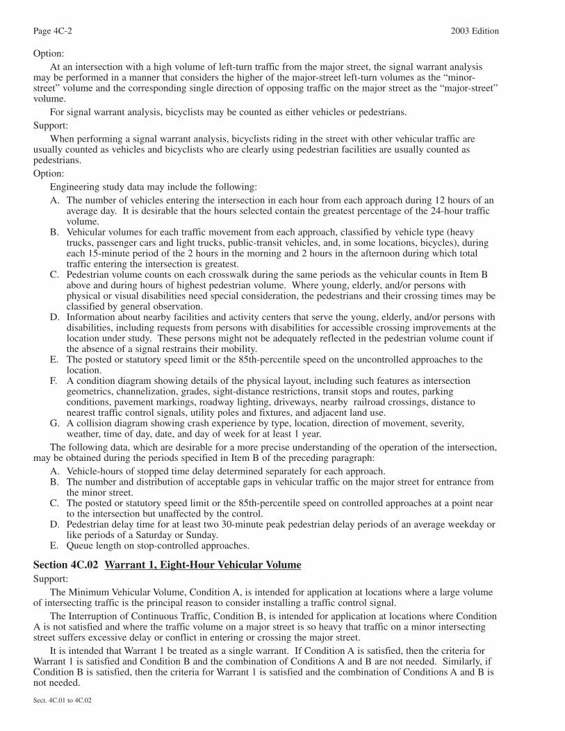
Section 4C.02 Warrant 1, Eight-Hour Vehicular VolumeSupport:
The Minimum Vehicular Volume, Condition A, is intended for application at locations where a large volumeof intersecting traffic is the principal reason to consider installing a traffic control signal.
The Interruption of Continuous Traffic, Condition B, is intended for application at locations where ConditionA is not satisfied and where the traffic volume on a major street is so heavy that traffic on a minor intersectingstreet suffers excessive delay or conflict in entering or crossing the major street.
It is intended that Warrant 1 be treated as a single warrant. If Condition A is satisfied, then the criteria forWarrant 1 is satisfied and Condition B and the combination of Conditions A and B are not needed. Similarly, ifCondition B is satisfied, then the criteria for Warrant 1 is satisfied and the combination of Conditions A and B isnot needed.
Page 4C-2 2003 Edition
Sect. 4C.01 to 4C.02
2003 Edition Page 4C-3
Sect. 4C.02
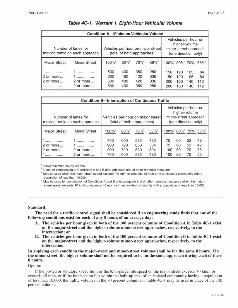
Table 4C-1. Warrant 1, Eight-Hour Vehicular Volume
Standard:The need for a traffic control signal shall be considered if an engineering study finds that one of the
following conditions exist for each of any 8 hours of an average day:A. The vehicles per hour given in both of the 100 percent columns of Condition A in Table 4C-1 exist
on the major-street and the higher-volume minor-street approaches, respectively, to theintersection; or
B. The vehicles per hour given in both of the 100 percent columns of Condition B in Table 4C-1 existon the major-street and the higher-volume minor-street approaches, respectively, to theintersection.
In applying each condition the major-street and minor-street volumes shall be for the same 8 hours. Onthe minor street, the higher volume shall not be required to be on the same approach during each of these8 hours.Option:
If the posted or statutory speed limit or the 85th-percentile speed on the major street exceeds 70 km/h orexceeds 40 mph, or if the intersection lies within the built-up area of an isolated community having a populationof less than 10,000, the traffic volumes in the 70 percent columns in Table 4C-1 may be used in place of the 100percent columns.
Number of lanes for moving traffic on each approach
Major Street Minor Street
1................. 1.................2 or more... 1.................2 or more... 2 or more ...1................. 2 or more ....
Vehicles per hour on major street(total of both approaches)
100%a 80%b 70%c 56%d
500 400 350 280600 480 420 336600 480 420 336500 400 350 280
Vehicles per hour on higher-volume
minor-street approach(one direction only)
100%a 80%b 70%c 56%d
150 120 105 84150 120 105 84200 160 140 112200 160 140 112
Condition A—Minimum Vehicular Volume
Number of lanes for moving traffic on each approach
Major Street Minor Street
1................. 1.................2 or more... 1.................2 or more... 2 or more ...1................. 2 or more ....
Condition B—Interruption of Continuous Traffic
Vehicles per hour on major street(total of both approaches)
100%a 80%b 70%c 56%d
750 600 525 420900 720 630 504900 720 630 504750 600 525 420
Vehicles per hour onhigher-volume
minor-street approach(one direction only)
100%a 80%b 70%c 56%d
75 60 53 4275 60 53 42100 80 70 56100 80 70 56
aBasic minimum hourly volume.
bUsed for combination of Conditions A and B after adequate trial of other remedial measures.
cMay be used when the major-street speed exceeds 70 km/h or exceeds 40 mph or in an isolated community with a population of less than 10,000.
dMay be used for combination of Conditions A and B after adequate trial of other remedial measures when the major-street speed exceeds 70 km/h or exceeds 40 mph or in an isolated community with a population of less than 10,000.
Guidance:The combination of Conditions A and B is intended for application at locations where Condition A is not
satisfied and Condition B is not satisfied and should be applied only after an adequate trial of other alternativesthat could cause less delay and inconvenience to traffic has failed to solve the traffic problems.Standard:
The need for a traffic control signal shall be considered if an engineering study finds that both of thefollowing conditions exist for each of any 8 hours of an average day:
A. The vehicles per hour given in both of the 80 percent columns of Condition A in Table 4C-1 existon the major-street and the higher-volume minor-street approaches, respectively, to theintersection; and
B. The vehicles per hour given in both of the 80 percent columns of Condition B in Table 4C-1 existon the major-street and the higher-volume minor-street approaches, respectively, to theintersection.
These major-street and minor-street volumes shall be for the same 8 hours for each condition; however,the 8 hours satisfied in Condition A shall not be required to be the same 8 hours satisfied in Condition B.On the minor street, the higher volume shall not be required to be on the same approach during each ofthe 8 hours.Option:
If the posted or statutory speed limit or the 85th-percentile speed on the major street exceeds 70 km/h orexceeds 40 mph, or if the intersection lies within the built-up area of an isolated community having a populationof less than 10,000, the traffic volumes in the 56 percent columns in Table 4C-1 may be used in place of the 80percent columns.
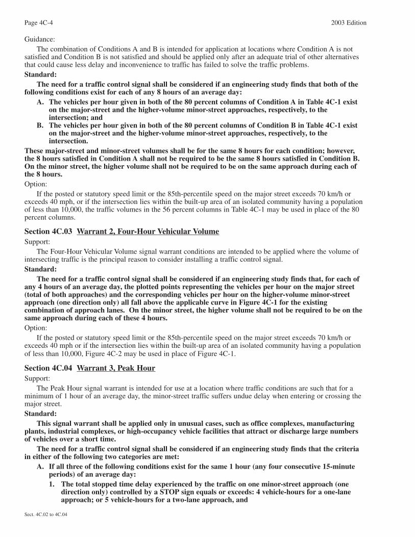
Section 4C.03 Warrant 2, Four-Hour Vehicular VolumeSupport:
The Four-Hour Vehicular Volume signal warrant conditions are intended to be applied where the volume ofintersecting traffic is the principal reason to consider installing a traffic control signal.Standard:
The need for a traffic control signal shall be considered if an engineering study finds that, for each ofany 4 hours of an average day, the plotted points representing the vehicles per hour on the major street(total of both approaches) and the corresponding vehicles per hour on the higher-volume minor-streetapproach (one direction only) all fall above the applicable curve in Figure 4C-1 for the existingcombination of approach lanes. On the minor street, the higher volume shall not be required to be on thesame approach during each of these 4 hours.Option:
If the posted or statutory speed limit or the 85th-percentile speed on the major street exceeds 70 km/h orexceeds 40 mph or if the intersection lies within the built-up area of an isolated community having a populationof less than 10,000, Figure 4C-2 may be used in place of Figure 4C-1.
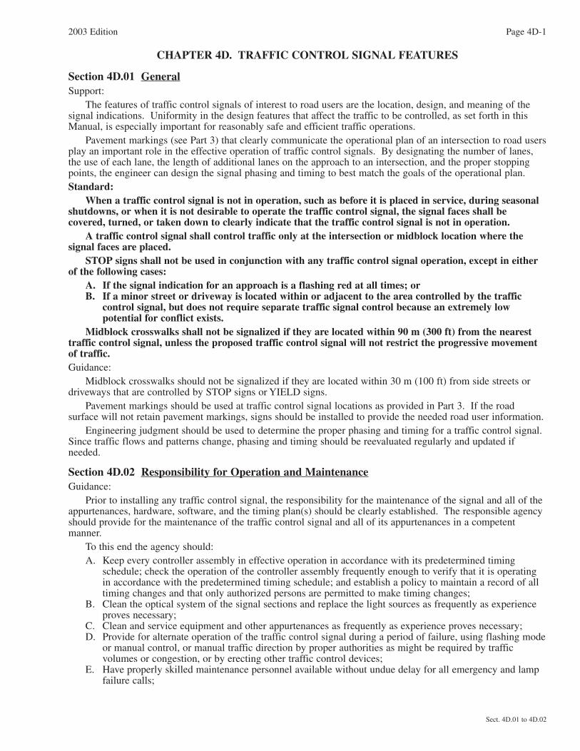
Section 4C.04 Warrant 3, Peak HourSupport:
The Peak Hour signal warrant is intended for use at a location where traffic conditions are such that for aminimum of 1 hour of an average day, the minor-street traffic suffers undue delay when entering or crossing themajor street.Standard:
This signal warrant shall be applied only in unusual cases, such as office complexes, manufacturingplants, industrial complexes, or high-occupancy vehicle facilities that attract or discharge large numbers of vehicles over a short time.
The need for a traffic control signal shall be considered if an engineering study finds that the criteriain either of the following two categories are met:
A. If all three of the following conditions exist for the same 1 hour (any four consecutive 15-minuteperiods) of an average day:1. The total stopped time delay experienced by the traffic on one minor-street approach (one
direction only) controlled by a STOP sign equals or exceeds: 4 vehicle-hours for a one-laneapproach; or 5 vehicle-hours for a two-lane approach, and
Page 4C-4 2003 Edition
Sect. 4C.02 to 4C.04
2003 Edition Page 4C-5
Sect. 4C.04
Figure 4C-2. Warrant 2, Four-Hour Vehicular Volume (70% Factor)
(COMMUNITY LESS THAN 10,000 POPULATION OR ABOVE 70 km/h OR ABOVE 40 mph ON MAJOR STREET)
2 OR MORE LANES & 2 OR MORE LANES
2 OR MORE LANES & 1 LANE
1 LANE & 1 LANE
300 400 500 600 700 800 900 1000 1100 1200 1300 1400
100
200
300
400
500
MIN
OR
ST
RE
ET
HIG
HE
R-V
OLU
ME
AP
PR
OA
CH
- V
PH
*115
*80
MAJOR STREET—TOTAL OF BOTH APPROACHES—VEHICLES PER HOUR (VPH)
*Note: 115 vph applies as the lower threshold volume for a minor-streetapproach with two or more lanes and 80 vph applies as the lower
threshold volume for a minor-street approach with one lane.
MIN
OR
ST
RE
ET
HIG
HE
R-V
OLU
ME
AP
PR
OA
CH
- V
PH
MAJOR STREET—TOTAL OF BOTH APPROACHES—VEHICLES PER HOUR (VPH)
*Note: 80 vph applies as the lower threshold volume for a minor-streetapproach with two or more lanes and 60 vph applies as the lower
threshold volume for a minor-street approach with one lane.
2 OR MORE LANES & 2 OR MORE LANES
2 OR MORE LANES & 1 LANE
1 LANE & 1 LANE
200 300 400 500 600 700 800 900 1000
100
200
300
400
*60*80
Figure 4C-1. Warrant 2, Four-Hour Vehicular Volume

2. The volume on the same minor-street approach (one direction only) equals or exceeds 100vehicles per hour for one moving lane of traffic or 150 vehicles per hour for two moving lanes,and
3. The total entering volume serviced during the hour equals or exceeds 650 vehicles per hour forintersections with three approaches or 800 vehicles per hour for intersections with four ormore approaches.
B. The plotted point representing the vehicles per hour on the major street (total of both approaches)and the corresponding vehicles per hour on the higher-volume minor-street approach (onedirection only) for 1 hour (any four consecutive 15-minute periods) of an average day falls abovethe applicable curve in Figure 4C-3 for the existing combination of approach lanes.
Option:If the posted or statutory speed limit or the 85th-percentile speed on the major street exceeds 70 km/h or
exceeds 40 mph, or if the intersection lies within the built-up area of an isolated community having a populationof less than 10,000, Figure 4C-4 may be used in place of Figure 4C-3 to satisfy the criteria in the secondcategory of the Standard.
Section 4C.05 Warrant 4, Pedestrian VolumeSupport:
The Pedestrian Volume signal warrant is intended for application where the traffic volume on a major streetis so heavy that pedestrians experience excessive delay in crossing the major street.Standard:
The need for a traffic control signal at an intersection or midblock crossing shall be considered if anengineering study finds that both of the following criteria are met:
A. The pedestrian volume crossing the major street at an intersection or midblock location during anaverage day is 100 or more for each of any 4 hours or 190 or more during any 1 hour; and
B. There are fewer than 60 gaps per hour in the traffic stream of adequate length to allow pedestriansto cross during the same period when the pedestrian volume criterion is satisfied. Where there is adivided street having a median of sufficient width for pedestrians to wait, the requirement appliesseparately to each direction of vehicular traffic.
The Pedestrian Volume signal warrant shall not be applied at locations where the distance to thenearest traffic control signal along the major street is less than 90 m (300 ft), unless the proposed trafficcontrol signal will not restrict the progressive movement of traffic.
If this warrant is met and a traffic control signal is justified by an engineering study, the traffic controlsignal shall be equipped with pedestrian signal heads conforming to requirements set forth in Chapter 4E.Guidance:
If this warrant is met and a traffic control signal is justified by an engineering study, then:A. If at an intersection, the traffic control signal should be traffic-actuated and should include pedestrian
detectors.B. If at a nonintersection crossing, the traffic control signal should be pedestrian-actuated, parking and other
sight obstructions should be prohibited for at least 30 m (100 ft) in advance of and at least 6.1 m (20 ft)beyond the crosswalk, and the installation should include suitable standard signs and pavement markings.
C. Furthermore, if installed within a signal system, the traffic control signal should be coordinated.Option:
The criterion for the pedestrian volume crossing the major roadway may be reduced as much as 50 percent ifthe average crossing speed of pedestrians is less than 1.2 m/sec (4 ft/sec).
A traffic control signal may not be needed at the study location if adjacent coordinated traffic control signalsconsistently provide gaps of adequate length for pedestrians to cross the street, even if the rate of gap occurrenceis less than one per minute.
Section 4C.06 Warrant 5, School CrossingSupport:
The School Crossing signal warrant is intended for application where the fact that school children cross themajor street is the principal reason to consider installing a traffic control signal.
Page 4C-6 2003 Edition
Sect. 4C.04 to 4C.06

2003 Edition Page 4C-7
Sect. 4C.06
Figure 4C-4. Warrant 3, Peak Hour (70% Factor)(COMMUNITY LESS THAN 10,000 POPULATION OR ABOVE 70 km/h OR ABOVE 40 mph ON MAJOR STREET)
1500400 500 600 700 800 900 1000 1100 1200 1300 1400
100
200
300
400
500
MIN
OR
ST
RE
ET
HIG
HE
R-V
OLU
ME
AP
PR
OA
CH
- V
PH
*150
*100
MAJOR STREET—TOTAL OF BOTH APPROACHES—VEHICLES PER HOUR (VPH)
*Note: 150 vph applies as the lower threshold volume for a minor-streetapproach with two or more lanes and 100 vph applies as the lower
threshold volume for a minor-street approach with one lane.
MAJOR STREET—TOTAL OF BOTH APPROACHES—VEHICLES PER HOUR (VPH)
*Note: 100 vph applies as the lower threshold volume for a minor-streetapproach with two or more lanes and 75 vph applies as the lower
threshold volume for a minor-street approach with one lane.
300 400 500 600 700 800 900 1000
MIN
OR
ST
RE
ET
HIG
HE
R-V
OLU
ME
AP
PR
OA
CH
- V
PH
100
200
300
400
*75*100
600
1600 1700 1800
1100 1200 1300
2 OR MORE LANES & 2 OR MORE LANES
2 OR MORE LANES & 1 LANE
1 LANE & 1 LANE
2 OR MORE LANES & 2 OR MORE LANES
2 OR MORE LANES & 1 LANE
1 LANE & 1 LANE
Figure 4C-3. Warrant 3, Peak Hour

Standard:The need for a traffic control signal shall be considered when an engineering study of the frequency
and adequacy of gaps in the vehicular traffic stream as related to the number and size of groups of schoolchildren at an established school crossing across the major street shows that the number of adequate gapsin the traffic stream during the period when the children are using the crossing is less than the number ofminutes in the same period (see Section 7A.03) and there are a minimum of 20 students during the highestcrossing hour.
Before a decision is made to install a traffic control signal, consideration shall be given to theimplementation of other remedial measures, such as warning signs and flashers, school speed zones, schoolcrossing guards, or a grade-separated crossing.
The School Crossing signal warrant shall not be applied at locations where the distance to the nearesttraffic control signal along the major street is less than 90 m (300 ft), unless the proposed traffic controlsignal will not restrict the progressive movement of traffic.Guidance:
If this warrant is met and a traffic control signal is justified by an engineering study, then:A. If at an intersection, the traffic control signal should be traffic-actuated and should include pedestrian
detectors.B. If at a nonintersection crossing, the traffic control signal should be pedestrian-actuated, parking and other
sight obstructions should be prohibited for at least 30 m (100 ft) in advance of and at least 6.1 m (20 ft)beyond the crosswalk, and the installation should include suitable standard signs and pavement markings.
C. Furthermore, if installed within a signal system, the traffic control signal should be coordinated.
Section 4C.07 Warrant 6, Coordinated Signal SystemSupport:
Progressive movement in a coordinated signal system sometimes necessitates installing traffic control signalsat intersections where they would not otherwise be needed in order to maintain proper platooning of vehicles.Standard:
The need for a traffic control signal shall be considered if an engineering study finds that one of thefollowing criteria is met:
A. On a one-way street or a street that has traffic predominantly in one direction, the adjacent trafficcontrol signals are so far apart that they do not provide the necessary degree of vehicularplatooning.
B. On a two-way street, adjacent traffic control signals do not provide the necessary degree ofplatooning and the proposed and adjacent traffic control signals will collectively provide aprogressive operation.
Guidance:The Coordinated Signal System signal warrant should not be applied where the resultant spacing of traffic
control signals would be less than 300 m (1,000 ft).
Section 4C.08 Warrant 7, Crash ExperienceSupport:
The Crash Experience signal warrant conditions are intended for application where the severity andfrequency of crashes are the principal reasons to consider installing a traffic control signal.Standard:
The need for a traffic control signal shall be considered if an engineering study finds that all of thefollowing criteria are met:
A. Adequate trial of alternatives with satisfactory observance and enforcement has failed to reducethe crash frequency; and
B. Five or more reported crashes, of types susceptible to correction by a traffic control signal, haveoccurred within a 12-month period, each crash involving personal injury or property damageapparently exceeding the applicable requirements for a reportable crash; and
C. For each of any 8 hours of an average day, the vehicles per hour (vph) given in both of the 80percent columns of Condition A in Table 4C-1 (see Section 4C.02), or the vph in both of the 80percent columns of Condition B in Table 4C-1 exists on the major-street and the higher-volumeminor-street approach, respectively, to the intersection, or the volume of pedestrian traffic is not
Page 4C-8 2003 Edition
Sect. 4C.06 to 4C.08

less than 80 percent of the requirements specified in the Pedestrian Volume warrant. These major-street and minor-street volumes shall be for the same 8 hours. On the minor street, the highervolume shall not be required to be on the same approach during each of the 8 hours.
Option:If the posted or statutory speed limit or the 85th-percentile speed on the major street exceeds 70 km/h or
exceeds 40 mph, or if the intersection lies within the built-up area of an isolated community having a populationof less than 10,000, the traffic volumes in the 56 percent columns in Table 4C-1 may be used in place of the 80percent columns.
Section 4C.09 Warrant 8, Roadway NetworkSupport:
Installing a traffic control signal at some intersections might be justified to encourage concentration andorganization of traffic flow on a roadway network.Standard:
The need for a traffic control signal shall be considered if an engineering study finds that the commonintersection of two or more major routes meets one or both of the following criteria:
A. The intersection has a total existing, or immediately projected, entering volume of at least 1,000vehicles per hour during the peak hour of a typical weekday and has 5-year projected trafficvolumes, based on an engineering study, that meet one or more of Warrants 1, 2, and 3 during anaverage weekday; or
B. The intersection has a total existing or immediately projected entering volume of at least 1,000vehicles per hour for each of any 5 hours of a nonnormal business day (Saturday or Sunday).
A major route as used in this signal warrant shall have one or more of the following characteristics:A. It is part of the street or highway system that serves as the principal roadway network for through
traffic flow; orB. It includes rural or suburban highways outside, entering, or traversing a City; orC. It appears as a major route on an official plan, such as a major street plan in an urban area traffic
and transportation study.
2003 Edition Page 4C-9
Sect. 4C.08 to 4C.09

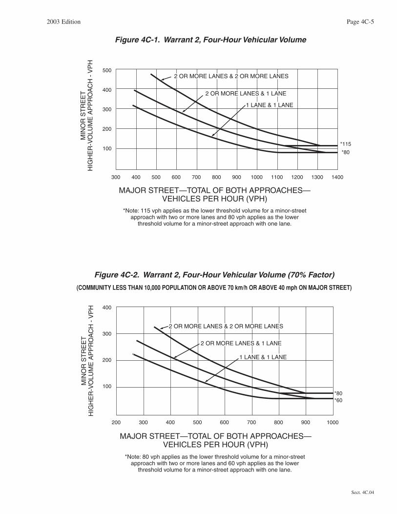
CHAPTER 4D. TRAFFIC CONTROL SIGNAL FEATURES
Section 4D.01 GeneralSupport:
The features of traffic control signals of interest to road users are the location, design, and meaning of thesignal indications. Uniformity in the design features that affect the traffic to be controlled, as set forth in thisManual, is especially important for reasonably safe and efficient traffic operations.
Pavement markings (see Part 3) that clearly communicate the operational plan of an intersection to road usersplay an important role in the effective operation of traffic control signals. By designating the number of lanes,the use of each lane, the length of additional lanes on the approach to an intersection, and the proper stoppingpoints, the engineer can design the signal phasing and timing to best match the goals of the operational plan.Standard:
When a traffic control signal is not in operation, such as before it is placed in service, during seasonalshutdowns, or when it is not desirable to operate the traffic control signal, the signal faces shall becovered, turned, or taken down to clearly indicate that the traffic control signal is not in operation.
A traffic control signal shall control traffic only at the intersection or midblock location where thesignal faces are placed.
STOP signs shall not be used in conjunction with any traffic control signal operation, except in eitherof the following cases:
A. If the signal indication for an approach is a flashing red at all times; orB. If a minor street or driveway is located within or adjacent to the area controlled by the traffic
control signal, but does not require separate traffic signal control because an extremely lowpotential for conflict exists.
Midblock crosswalks shall not be signalized if they are located within 90 m (300 ft) from the nearesttraffic control signal, unless the proposed traffic control signal will not restrict the progressive movementof traffic.Guidance:
Midblock crosswalks should not be signalized if they are located within 30 m (100 ft) from side streets ordriveways that are controlled by STOP signs or YIELD signs.
Pavement markings should be used at traffic control signal locations as provided in Part 3. If the roadsurface will not retain pavement markings, signs should be installed to provide the needed road user information.
Engineering judgment should be used to determine the proper phasing and timing for a traffic control signal.Since traffic flows and patterns change, phasing and timing should be reevaluated regularly and updated ifneeded.
Section 4D.02 Responsibility for Operation and MaintenanceGuidance:
Prior to installing any traffic control signal, the responsibility for the maintenance of the signal and all of theappurtenances, hardware, software, and the timing plan(s) should be clearly established. The responsible agencyshould provide for the maintenance of the traffic control signal and all of its appurtenances in a competentmanner.
To this end the agency should:A. Keep every controller assembly in effective operation in accordance with its predetermined timing
schedule; check the operation of the controller assembly frequently enough to verify that it is operatingin accordance with the predetermined timing schedule; and establish a policy to maintain a record of alltiming changes and that only authorized persons are permitted to make timing changes;
B. Clean the optical system of the signal sections and replace the light sources as frequently as experienceproves necessary;
C. Clean and service equipment and other appurtenances as frequently as experience proves necessary;D. Provide for alternate operation of the traffic control signal during a period of failure, using flashing mode
or manual control, or manual traffic direction by proper authorities as might be required by trafficvolumes or congestion, or by erecting other traffic control devices;
E. Have properly skilled maintenance personnel available without undue delay for all emergency and lampfailure calls;
2003 Edition Page 4D-1
Sect. 4D.01 to 4D.02

Page 4D-2 2003 Edition
Sect. 4D.02 to 4D.04
F. Provide spare equipment to minimize the interruption of traffic control signal operation as a result ofequipment failure;
G. Provide for the availability of properly skilled maintenance personnel for the repair of all components;and
H. Maintain the appearance of the signal displays and equipment.
Section 4D.03 Provisions for PedestriansSupport:
Chapter 4E contains additional information regarding pedestrian signals.Standard:
The design and operation of traffic control signals shall take into consideration the needs of pedestrianas well as vehicular traffic.
If engineering judgment indicates the need for provisions for a given pedestrian movement, signalfaces conveniently visible to pedestrians shall be provided by pedestrian signal heads or a signal face foran adjacent vehicular movement.Guidance:
Safety considerations should include the installation, where appropriate, of accessible pedestrian signals (see Sections 4E.06 and 4E.09) that provide information in nonvisual format (such as audible tones, verbalmessages, and/or vibrating surfaces).
Where pedestrian movements regularly occur, pedestrians should be provided with sufficient time to crossthe roadway by adjusting the traffic control signal operation and timing to provide sufficient crossing time everycycle or by providing pedestrian detectors.Option:
If it is desirable to prohibit certain pedestrian movements at a traffic control signal, a PEDESTRIANSPROHIBITED (R9-3) or No Pedestrian Crossing (R9-3a) sign may be used (see Section 2B.44).
Section 4D.04 Meaning of Vehicular Signal IndicationsSupport:
The “Uniform Vehicle Code” (see Section 1A.11) is the primary source for the standards for the meaning ofvehicular signal indications to both vehicle operators and pedestrians as set forth below, and the standards for themeaning of separate pedestrian signal indications as set forth in Section 4E.02.Standard:
The following meanings shall be given to highway traffic signal indications for vehicles andpedestrians:
A. Steady green signal indications shall have the following meanings:1. Traffic, except pedestrians, facing a CIRCULAR GREEN signal indication is permitted to
proceed straight through or turn right or left except as such movement is modified by lane-usesigns, turn prohibition signs, lane markings, or roadway design. But vehicular traffic,including vehicles turning right or left, shall yield the right-of-way to other vehicles, and topedestrians lawfully within the intersection or an adjacent crosswalk, at the time such signalindication is exhibited.
2. Traffic, except pedestrians, facing a GREEN ARROW signal indication, shown alone or incombination with another signal indication, is permitted to cautiously enter the intersectiononly to make the movement indicated by such arrow, or such other movement as is permittedby other signal indications shown at the same time. Such vehicular traffic shall yield the right-of-way to pedestrians lawfully within an adjacent crosswalk and to other traffic lawfully usingthe intersection.
3. Unless otherwise directed by a pedestrian signal head, pedestrians facing any green signalindication, except when the sole green signal indication is a turn arrow, are permitted toproceed across the roadway within any marked or unmarked crosswalk. The pedestrian shallyield the right-of-way to vehicles lawfully within the intersection at the time that the greensignal indication is first shown.
B. Steady yellow signal indications shall have the following meanings:1. Traffic, except pedestrians, facing a steady CIRCULAR YELLOW or YELLOW ARROW
signal indication is thereby warned that the related green movement is being terminated orthat a red signal indication will be exhibited immediately thereafter when vehicular trafficshall not enter the intersection.

2. Pedestrians facing a steady CIRCULAR YELLOW or YELLOW ARROW signal indication,unless otherwise directed by a pedestrian signal head, are thereby advised that there isinsufficient time to cross the roadway before a red signal indication is shown, and nopedestrian shall then start to cross the roadway.
C. Steady red signal indications shall have the following meanings:1. Vehicular traffic facing a steady CIRCULAR RED signal indication alone shall stop at a
clearly marked stop line, but if there is no stop line, traffic shall stop before entering thecrosswalk on the near side of the intersection; or if there is no crosswalk, then before enteringthe intersection, and shall remain stopped until a signal indication to proceed is shown, or asprovided below.
Except when a sign is in place prohibiting a turn on red or a RED ARROW signalindication is displayed, vehicular traffic facing a CIRCULAR RED signal indication ispermitted to enter the intersection to turn right, or to turn left from a one-way street into aone-way street, after stopping. Such vehicular traffic shall yield the right-of-way to pedestrianslawfully within an adjacent crosswalk and to other traffic lawfully using the intersection.
2. Vehicular traffic facing a steady RED ARROW signal indication shall not enter the intersectionto make the movement indicated by the arrow and, unless entering the intersection to makeanother movement permitted by another signal indication, shall stop at a clearly marked stopline; but if there is no stop line, before entering the crosswalk on the near side of theintersection, or if there is no crosswalk, then before entering the intersection, and shall remainstopped until a signal indication permitting the movement indicated by such RED ARROW isshown.
When an R10-17a sign (see Section 2B.45) is in place permitting a turn on a RED ARROWsignal indication, vehicular traffic facing a RED ARROW signal indication is permitted toenter the intersection to turn right, or to turn left from a one-way street into a one-way street,after stopping. Such vehicular traffic shall yield the right-of-way to pedestrians lawfully withinan adjacent crosswalk and to other traffic lawfully using the intersection.
3. Unless otherwise directed by a pedestrian signal head, pedestrians facing a steady CIRCULARRED or RED ARROW signal indication alone shall not enter the roadway.
D. Flashing signal indications shall have the following meanings:1. Flashing yellow—When a yellow lens is illuminated with rapid intermittent flashes, vehicular
traffic is permitted to proceed through the intersection or past such signal indication only withcaution.
2. Flashing red—When a red lens is illuminated with rapid intermittent flashes, vehicular trafficshall stop at a clearly marked stop line; but if there is no stop line, traffic shall stop beforeentering the crosswalk on the near side of the intersection; or if there is no crosswalk, at thepoint nearest the intersecting roadway where the driver has a view of approaching traffic onthe intersecting roadway before entering the intersection. The right to proceed shall be subjectto the rules applicable after making a stop at a STOP sign.
3. Flashing RED ARROW and flashing YELLOW ARROW signal indications have the samemeaning as the corresponding flashing circular signal indication, except that they apply only tovehicular traffic intending to make the movement indicated by the arrow.
Section 4D.05 Application of Steady Signal IndicationsStandard:
When a traffic control signal is being operated in a steady (stop-and-go) mode, at least one lens in eachsignal face shall be illuminated at any given time.
A signal face(s) that controls a particular vehicular movement during any interval of a cycle shallcontrol that same movement during all intervals of the cycle.
Steady signal indications shall be applied as follows:A. A steady CIRCULAR RED signal indication:
1. Shall be displayed when it is intended to prohibit traffic, except pedestrians directed by apedestrian signal head, from entering the intersection or other controlled area. Turning afterstopping is permitted as stated in Item C.1 of Section 4D.04.
2. Shall be displayed with the appropriate GREEN ARROW signal indications when it isintended to permit traffic to make a specified turn or turns, and to prohibit traffic fromproceeding straight ahead through the intersection or other controlled area, except in protectedonly mode turn signal faces, or in protected/permissive mode left-turn operation with separateleft-turn signal faces (see Section 4D.06).
2003 Edition Page 4D-3
Sect. 4D.04 to 4D.05

Page 4D-4 2003 Edition
Sect. 4D.05
B. A steady CIRCULAR YELLOW signal indication:1. Shall be displayed following a CIRCULAR GREEN or straight-through GREEN ARROW
signal indication in the same signal face.2. Shall not be displayed in conjunction with the change from the CIRCULAR RED signal
indication to the CIRCULAR GREEN signal indication.3. Shall be followed by a CIRCULAR RED signal indication except that, when entering
preemption operation, the return to the previous CIRCULAR GREEN signal indication shallbe permitted following a CIRCULAR YELLOW signal indication (see Section 4D.13).
4. Shall not be displayed to an approach from which drivers are turning left permissively unlessone of the following conditions exists:(a) A steady CIRCULAR YELLOW signal indication is also being shown simultaneously to the
opposing approach;(b) A separate left-turn signal face is provided and operated as described in Section 4D.06;(c) An engineering study has determined that, because of unique intersection conditions, the
conditions described in items (a) and (b) above cannot reasonably be implemented withoutcausing significant operational or safety problems and that the volume of impacted left-turning traffic is relatively low, and those left-turning drivers are advised that the opposingtraffic is not simultaneously being shown a CIRCULAR YELLOW signal indication if thisoperation occurs continuously by the installation near the left-most signal head of a W25-1sign (see Section 2C.39) with the legend ONCOMING TRAFFIC HAS EXTENDEDGREEN; or
(d) Drivers are advised of the operation if it occurs only occasionally, such as during apreemption sequence or because of the skipping of actuated phases, by the installation nearthe left-most signal head of a W25-2 sign (see Section 2C.39) with the legend ONCOMINGTRAFFIC MAY HAVE EXTENDED GREEN.
C. A steady CIRCULAR GREEN signal indication shall be displayed only when it is intended topermit traffic to proceed in any direction that is lawful and practical.
D. A steady RED ARROW signal indication shall be displayed when it is intended to prohibit traffic,except pedestrians directed by a pedestrian signal head, from entering the intersection or othercontrolled area to make the indicated turn. Except as described in Item C.2 of Section 4D.04,turning on a steady RED ARROW signal indication shall not be permitted.
E. A steady YELLOW ARROW signal indication:1. Shall be displayed in the same direction as a GREEN ARROW signal indication following a
GREEN ARROW signal indication in the same signal face, unless:(a) The GREEN ARROW signal indication and a CIRCULAR GREEN (or straight-through
GREEN ARROW) signal indication terminate simultaneously in the same signal face, or(b) The green arrow is a straight-through GREEN ARROW.
2. Shall not be displayed in conjunction with the change from a RED ARROW signal indicationto a GREEN ARROW signal indication.
3. Shall not be displayed when any conflicting vehicular movement has a green or yellow signalindication or any conflicting pedestrian movement has a WALKING PERSON (symbolizingWALK) or flashing UPRAISED HAND (symbolizing DONT WALK) signal indication (seeSection 4D.09).
4. Shall be terminated by a RED ARROW signal indication for the same direction or aCIRCULAR RED signal indication except:(a) When entering preemption operation, the return to the previous GREEN ARROW signal
indication shall be permitted following a YELLOW ARROW signal indication.(b) When the movement controlled by the arrow is to continue on a permissive mode basis
during an immediately following CIRCULAR GREEN signal indication.F. A steady GREEN ARROW signal indication:
1. Shall be displayed only to allow vehicular movements, in the direction indicated, that are not inconflict with other vehicles moving on a green or yellow signal indication or with pedestrianscrossing in conformance with a WALKING PERSON (symbolizing WALK) or flashingUPRAISED HAND (symbolizing DONT WALK) signal indication (see Section 4D.09).
2. Shall be displayed on a signal face that controls a left-turn movement when said movement isnot in conflict with other vehicles moving on a green or yellow signal indication or withpedestrians crossing in conformance with a WALKING PERSON (symbolizing WALK) orflashing UPRAISED HAND (symbolizing DONT WALK) signal indication (see Section 4D.09).
3. Shall not be required on the stem of T-intersections or for turns from one-way streets.

2003 Edition Page 4D-5
Sect. 4D.05 to 4D.06
Option:Steady RED ARROW, YELLOW ARROW, and GREEN ARROW signal indications, if not otherwise
prohibited, may be used instead of the corresponding circular signal indications at the following locations:A. On an approach intersecting a one-way street;B. Where certain movements are prohibited; andC. Where certain movements are physically impossible.If U-turns are permitted from the approach and if drivers making a right turn from the conflicting approach
to the left are simultaneously being shown a right-turn GREEN ARROW signal indication, drivers making a U-turn may be advised of the operation by the installation near the left-turn signal face of a U-TURN YIELD TO RIGHT TURN (R10-16) sign (see Section 2B.45).
Section 4D.06 Application of Steady Signal Indications for Left TurnsSupport:
Left-turning traffic is controlled by one of four modes as follows:A. Permissive Only Mode—turns made on the CIRCULAR GREEN signal indication after yielding to
oncoming traffic and pedestrians;B. Protected Only Mode—turns made only when the left-turn GREEN ARROW signal indication is
displayed;C. Protected/Permissive Mode—both modes occur on an approach during the same cycle; orD. Variable Left-Turn Mode—the operating mode changes among the protected only mode and/or the
protected/permissive mode and/or the permissive only mode during different periods of the day.Option:
In areas having a high percentage of elderly drivers, special consideration may be given to the use ofprotected only mode left-turn phasing, when appropriate.Standard:
The required left-turn signal faces and operation for an approach shall be determined by the selectedmode of left-turn operation, as follows:
A. Permissive Only Mode—The signal indications for permissive only mode left turns shall beprovided by the signal faces controlling the through movement, or by a permissive-only left-turnsignal face that is either a shared signal face or a separate signal face. A permissive-only sharedsignal face, regardless of where the permissive-only left-turn signal face is positioned andregardless of how many adjacent through signal faces are provided, shall always simultaneouslydisplay the same color of circular indication that the adjacent through signal face or faces display.A separate permissive-only left-turn signal face sometimes displays a different color of circularsignal indication than the adjacent through signal faces display.
If a separate left-turn signal face is provided for permissive only left turns, it shall meet thefollowing requirements:1. During the permissive left-turn movement, the left-turn signal face shall display a CIRCULAR
GREEN signal indication.2. If the CIRCULAR GREEN and CIRCULAR YELLOW signal indications in the left-turn
signal face are visibility-limited from the adjacent through movement, the left-turn signal faceshall not be required to simultaneously display the same color of circular signal indication asthe signal faces for the adjacent through movement.
3. If the CIRCULAR GREEN and CIRCULAR YELLOW signal indications in the left-turnsignal face are visibility-limited from the adjacent through movement, the display of aCIRCULAR GREEN signal indication for a permissive left-turn movement while the signalfaces for the adjacent through movement display CIRCULAR RED signal indications and theopposing left-turn signal faces display left-turn GREEN ARROW signal indications for aprotected left-turn movement shall be permitted.
4. If the left-turn signal face does not simultaneously display the same color of circular signalindication as the signal faces for the adjacent through movement, a LEFT TURN YIELD ONGREEN (symbolic green ball) (R10-12) sign or a LEFT TURN SIGNAL—YIELD ON GREEN(symbolic green ball) (R10-21) sign (see Figure 2B-19) shall be used.
B. Protected Only Mode—The left-turn signal face shall be capable of displaying one of the followingsets of signal indications:1. Left-turn RED ARROW, YELLOW ARROW, and GREEN ARROW signal indications only.
At least one left-turn signal face shall be provided in addition to the two approach signal faces
Page 4D-6 2003 Edition
Sect. 4D.06
required in Section 4D.15 for the major movement. Only one of the three colors shall beilluminated at any given time. A signal instruction sign shall not be required with this set ofsignal indications. If used, it shall be a LEFT ON GREEN ARROW ONLY sign (R10-5).
2. CIRCULAR RED, left-turn YELLOW ARROW, and left-turn GREEN ARROW signalindications. At least one left-turn signal face shall be provided in addition to the two approachsignal faces required in Section 4D.15 for the major movement. Only one of the three colorsshall be illuminated at any given time. Unless the CIRCULAR RED signal indication isshielded, hooded, louvered, positioned, or designed such that it is not readily visible to driversin the through lane(s), a LEFT TURN SIGNAL sign (R10-10) shall be used.
3. CIRCULAR RED, CIRCULAR YELLOW, CIRCULAR GREEN, and left-turn GREENARROW signal indications. This four-section signal face shall be used only when theCIRCULAR GREEN and left-turn GREEN ARROW signal indications begin and terminatetogether. During each interval, the circular signal indication shall be the same color as thesignal indication on the signal face(s) for the adjacent through traffic.
C. Protected/Permissive Mode—The signal indications for protected/permissive mode left turns shallbe provided in either a shared signal face or a separate signal face. Any protected/permissive left-turn signal face that always simultaneously displays the same color of circular signal indicationthat the adjacent through signal faces display shall be considered to be a shared signal face,regardless of where the left-turn signal face is positioned and regardless of how many adjacentthrough signal faces are provided. Any protected/permissive left-turn signal face that sometimesdisplays a different color of circular signal indication than the adjacent through signal facesdisplay shall be considered to be a separate signal face. The requirements for each type of signalface are as follows:1. If a shared signal face is provided, it shall be considered an approach signal face, and shall
meet the following requirements:(a) During the protected left-turn movement, the signal face shall simultaneously display a left-
turn GREEN ARROW signal indication and a circular signal indication that is the samecolor as the signal indication for the adjacent through lane on the same approach as theprotected left turn.During the protected left-turn movement, the signal faces for through traffic on theopposing approach shall simultaneously display CIRCULAR RED signal indications.
(b) During the permissive left-turn movement, all signal faces on the approach shall displayCIRCULAR GREEN signal indications.
(c) All signal faces on the approach shall simultaneously display the same color of circularsignal indications to both through and left-turn road users.
(d) A supplementary sign shall not be required. If used, it shall be a LEFT TURN YIELD ONGREEN (symbolic green ball) (R10-12) sign (see Figure 2B-19).
2. If a separate signal face is provided, it shall be considered a left-turn signal face, and shall meetthe following requirements:(a) During the protected left-turn movement, the left-turn signal face shall display a left-turn
GREEN ARROW signal indication. During the protected left-turn movement, the signal faces for through traffic on theopposing approach shall simultaneously display CIRCULAR RED signal indications.
(b) During the permissive left-turn movement, the left-turn signal face shall display aCIRCULAR GREEN signal indication.
(c) If the CIRCULAR GREEN and CIRCULAR YELLOW signal indications in the left-turnsignal face are visibility-limited from the adjacent through movement, the left-turn signalface shall not be required to simultaneously display the same color of circular signalindication as the signal faces for the adjacent through movement.
(d) If the CIRCULAR GREEN and CIRCULAR YELLOW signal indications in the left-turnsignal face are visibility-limited from the adjacent through movement, the display of aCIRCULAR GREEN signal indication for a permissive left-turn movement while the signalfaces for the adjacent through movement display CIRCULAR RED signal indications andthe opposing left-turn signal face displays a left-turn GREEN ARROW for a protected left-turn movement shall be permitted.
(e) If the left-turn signal face does not simultaneously display the same color of circular signalindication as the signal faces for the adjacent through movement, a LEFT TURNSIGNAL—YIELD ON GREEN (symbolic green ball) (R10-21) sign (see Figure 2B-19) shallbe used.
2003 Edition Page 4D-7
Sect. 4D.06 to 4D.07
D. Variable Left-Turn Mode—If the protected only mode occurs during one or more periods of theday, and the permissive only mode or the combined protected/permissive mode occurs during otherperiods of the day, the requirements of Items A, B, and C in this Standard that are appropriate tothat mode of operation shall be met, subject to the following:1. The CIRCULAR GREEN and CIRCULAR YELLOW signal indications shall not be displayed
when operating in the protected only mode.2. The left-turn GREEN ARROW and left-turn YELLOW ARROW signal indications shall not be
displayed when operating in the permissive only mode.Option:
Additional appropriate signal indications or changeable message signs may be used to meet the requirementsfor the variable left-turn mode.
Section 4D.07 Application of Steady Signal Indications for Right TurnsSupport:
Right-turning traffic is controlled by one of four modes as follows:A. Permissive Only Mode—turns made on the CIRCULAR GREEN signal indication after yielding to
pedestrians.B. Protected Only Mode—turns made only when the right-turn GREEN ARROW signal indication is
displayed.C. Protected/Permissive Mode—both modes occur on an approach during the same cycle.D. Variable Right-Turn Mode—the operating mode changes among the protected only mode and/or the
protected/permissive mode and/or the permissive only mode during different periods of the day.Standard:
The required right-turn signal faces and operation for an approach shall be determined by the selectedmode of right-turn operation, as follows:
A. Permissive Only Mode—A separate signal indication or signal face for right turns shall not berequired. The signal indication for permissive only mode right turns shall be the same color as thesignal indication for adjacent through traffic, except that if the right turn is held to provide anexclusive pedestrian movement, a separate right-turn RED ARROW signal indication shall beprovided.
B. Protected Only Mode—The right-turn signal face shall be capable of displaying one of thefollowing sets of signal indications: 1. Right-turn RED ARROW, YELLOW ARROW, and GREEN ARROW signal indications only.
At least one right-turn signal face shall be provided in addition to the two approach signalfaces required in Section 4D.15 for the major movement. Only one of the three colors shall beilluminated at any given time. A signal instruction sign shall not be required with this set ofsignal indications. If used, it shall be a RIGHT ON GREEN ARROW ONLY sign (R10-5a).
2. CIRCULAR RED, right-turn YELLOW ARROW, and right-turn GREEN ARROW signalindications. At least one right-turn signal face shall be provided in addition to the twoapproach signal faces required in Section 4D.15 for the major movement. Only one of threecolors shall be illuminated at any given time. Unless the CIRCULAR RED signal indication isshielded, hooded, louvered, positioned, or designed such that it is not readily visible to driversin the through lane(s), a RIGHT TURN SIGNAL sign (R10-10R) shall be used.
3. CIRCULAR RED, CIRCULAR YELLOW, CIRCULAR GREEN, and right-turn GREENARROW signal indications. This four-section signal face shall be used only when theCIRCULAR GREEN and right-turn GREEN ARROW signal indications begin and terminatetogether. During each interval, the circular signal indication shall be the same color as thesignal indication on the signal faces for the adjacent through traffic.
C. Protected/Permissive Mode—A separate signal face is not required for the right turn, but, ifprovided, it shall be considered an approach signal face, and shall meet the followingrequirements:1. During the protected right-turn movement, the signal face shall simultaneously display:
(a) A right-turn GREEN ARROW signal indication, and(b) A circular signal indication that is the same color as the signal indication for the adjacent
through lane on the same approach as the protected right turn.2. During the permissive right-turn movement, all signal faces on the approach shall display a
CIRCULAR GREEN signal indication.

Page 4D-8 2003 Edition
Sect. 4D.07 to 4D.10
3. All signal faces on the approach shall simultaneously display the same color of circular signalindications to both through and right-turn road users.
D. Variable Right-Turn Mode—If the protected only mode occurs during one or more periods of theday, and the permissive only mode or the combined protected/permissive mode occurs during otherperiods of the day, the requirements of Items A, B, and C in this Standard that are appropriate tothat mode of operation shall be met subject to the following:1. The CIRCULAR GREEN and CIRCULAR YELLOW signal indications shall not be displayed
when operating in the protected only mode.2. The right-turn GREEN ARROW and right-turn YELLOW ARROW signal indications shall
not be displayed when operating in the permissive only mode.Option:
Additional appropriate signal indications or changeable message signs may be used to meet the requirementsfor the variable right-turn mode.
Section 4D.08 Prohibited Steady Signal IndicationsStandard:
The following combinations of signal indications shall not be simultaneously displayed on any onesignal face:
A. CIRCULAR GREEN with CIRCULAR YELLOW.B. CIRCULAR RED with CIRCULAR YELLOW.C. CIRCULAR GREEN with CIRCULAR RED.D. Straight-through GREEN ARROW with CIRCULAR RED.The above combinations shall not be simultaneously displayed in different signal faces on any one
approach unless one of the following conditions exists:A. One of the signal faces is a turn signal controlling a protected only mode turn, and a LEFT
(RIGHT) TURN SIGNAL sign (R10-10) (see Sections 4D.06 and 4D.07) is mounted adjacent toeach such signal face, or
B. The signal faces are shielded, hooded, louvered, positioned, or designed so that the combination isnot confusing to approaching road users.
A straight-through RED ARROW signal indication or a straight-through YELLOW ARROW signalindication shall not be displayed on any signal face, either alone or in combination with any other signalindication.
Section 4D.09 Unexpected Conflicts During Green or Yellow IntervalsStandard:
A steady GREEN ARROW or YELLOW ARROW signal indication shall not be displayed to vehicularmovements that are in conflict with the following:
A. Other vehicles moving on a green or yellow signal indication, except for the situation regarding U-turns described in Section 4D.05. Vehicles departing in the same direction shall not beconsidered in conflict if, for each turn lane with moving traffic, there is a separate departing lane,and pavement markings or raised channelization clearly indicate which departure lane to use.
B. Pedestrians crossing in conformance with a WALKING PERSON (symbolizing WALK) or flashingUPRAISED HAND (symbolizing DONT WALK) signal indication.
Guidance:No movement that creates an unexpected crossing of pathways of moving vehicles or pedestrians should be
allowed during any green or yellow interval, except when all three of the following conditions are met:A. The movement involves only slight conflict, andB. Serious traffic delays are substantially reduced by permitting the conflicting movement, andC. Drivers and pedestrians subjected to the unexpected conflict are effectively warned thereof by a sign.
Section 4D.10 Yellow Change and Red Clearance IntervalsStandard:
A yellow signal indication shall be displayed following every CIRCULAR GREEN or GREENARROW signal indication.
The exclusive function of the yellow change interval shall be to warn traffic of an impending change inthe right-of-way assignment.

The duration of a yellow change interval shall be predetermined.Guidance:
A yellow change interval should have a duration of approximately 3 to 6 seconds. The longer intervalsshould be reserved for use on approaches with higher speeds.Option:
The yellow change interval may be followed by a red clearance interval to provide additional time beforeconflicting traffic movements, including pedestrians, are released.Standard:
The duration of a red clearance interval shall be predetermined.Guidance:
A red clearance interval should have a duration not exceeding 6 seconds.
Section 4D.11 Application of Flashing Signal IndicationsStandard:
The light source of a flashing signal indication shall be flashed continuously at a rate of not less than50 nor more than 60 times per minute. The illuminated period of each flash shall be not less than half andnot more than two-thirds of the total flash cycle.
Flashing signal indications shall comply with the requirements of other Sections of this Manualregarding shielding or positioning of conflicting signal indications, except that flashing yellow signalindications for through traffic shall not be required to be shielded or positioned to prevent visual conflictfor road users in separately controlled turn lanes.
The following applications shall apply whenever a traffic control signal is operated in the flashingmode:
A. Each approach or protected only mode turn movement that is controlled during steady mode(stop-and-go) operation shall display a signal indication during flashing operation.
B. All signal faces that are flashed on an approach shall flash the same color, either yellow or red,except that separate signal faces for protected only mode turn movements and separate signal facesfor protected/permissive left-turn movements shall be permitted to flash a CIRCULAR RED orRED ARROW signal indication when the through signal indications are flashed yellow. Sharedsignal faces for protected/permissive left-turn movements shall not be permitted to flash aCIRCULAR RED signal indication when the through signal indications are flashed yellow.
C. The appropriate RED ARROW or YELLOW ARROW signal indication shall be flashed when asignal face consists entirely of arrow lenses.
D. If a signal face includes both circular and arrow signal lenses of the color that is to be flashed, onlythe circular signal indication shall be flashed.
Guidance:When a traffic control signal is operated in the flashing mode, a flashing yellow signal indication should be
used for the major street and a flashing red signal indication should be used for the other approaches unlessflashing red signal indications are used on all approaches.
Section 4D.12 Flashing Operation of Traffic Control SignalsStandard:
Each traffic control signal shall be provided with an independent flasher mechanism that operates incompliance with Section 4D.11. The flashing operation shall not be terminated by removal or turn off ofthe controller unit or of the conflict monitor (malfunction management unit) or both.
When a traffic control signal is operated in the flashing mode:A. Flashing yellow signal indications shall not be displayed for approaches with conflicting traffic
movements, except for permissive left-turn movements.B. At least one signal indication in each signal face on an approach shall be flashed except in the
following circumstance:A single-section signal face consisting of a continuously-illuminated GREEN ARROW signal lensthat is used alone to indicate a continuous movement in the steady (stop-and-go) mode shall remaincontinuously illuminated when the traffic control signal is operated in the flashing mode.
A manual switch, a conflict monitor (malfunction management unit) circuit, and, if appropriate,automatic means shall be provided to initiate the flashing mode.
2003 Edition Page 4D-9
Sect. 4D.10 to 4D.12

The transition from steady (stop-and-go) mode to flashing mode, if initiated by a conflict monitor(malfunction management unit) or by a manual switch, shall be permitted to be made at any time.
Programmed changes from steady (stop-and-go) mode to flashing mode shall be made under either ofthe following circumstances:
A. At the end of the common major-street red interval (such as just prior to the start of the green inboth directions on the major street), or
B. Directly from a steady CIRCULAR GREEN or GREEN ARROW signal indication to a flashingCIRCULAR YELLOW or YELLOW ARROW signal indication, respectively.
During programmed changes, no steady green signal indication or flashing yellow signal indicationshall be terminated and immediately followed by a steady red or flashing red signal indication withoutfirst displaying the steady yellow signal indication.
Changes from flashing mode to steady (stop-and-go) mode shall be made under one of the followingprocedures:
A. Yellow-red flashing mode: Changes from flashing mode to steady (stop-and-go) mode shall bemade at the beginning of the major-street green interval (when a green signal indication is shownto through traffic in both directions on the major street), or if there is no common major-streetgreen interval, at the beginning of the green interval for the major traffic movement on the majorstreet.
B. Red-red flashing mode: Changes from flashing mode to steady (stop-and-go) mode shall be madeby changing the flashing red indications to steady red indications followed by appropriate greenindications to begin the steady mode cycle. These green indications shall be the beginning of themajor-street green interval (when a green signal indication is shown to through traffic in bothdirections on the major street) or if there is no common major-street green interval, at thebeginning of the green interval for the major traffic movement on the major street.
Guidance:When changing from the yellow-red flashing mode to steady (stop-and-go) mode, if there is no common
major-street green interval, the provision of a steady red clearance interval for the other approaches beforechanging from a flashing yellow or a flashing red signal indication to a green signal indication on the majorapproach should be considered.
The steady red clearance interval provided during the change from red-red flashing mode to steady (stop-and-go) mode should have a duration of 6 seconds.Support:
Section 4E.09 contains information regarding the operation of accessible pedestrian signal detectorpushbutton locator tones during flashing operation.
Section 4D.13 Preemption and Priority Control of Traffic Control SignalsOption:
Traffic control signals may be designed and operated to respond to certain classes of approaching vehicles byaltering the normal signal timing and phasing plan(s) during the approach and passage of those vehicles. Thealternative plan(s) may be as simple as extending a currently displayed green interval or as complex as replacingthe entire set of signal phases and timing.Support:
Preemption control (see definition in Section 4A.02) is typically given to trains, boats, emergency vehicles,and light rail transit.
Examples of preemption control include the following:A. The prompt displaying of green signal indications at signalized locations ahead of fire vehicles, law
enforcement vehicles, ambulances, and other official emergency vehicles;B. A special sequence of signal phases and timing to provide additional clearance time for vehicles to clear
the tracks prior to the arrival of a train; andC. A special sequence of signal phases to display a red indication to prohibit turning movements towards
the tracks during the approach or passage of a train or transit vehicle.Priority control (see definition in Section 4A.02) is typically given to certain nonemergency vehicles such as
buses and light-rail vehicles.Examples of priority control include the following:A. The displaying of early or extended green signal indications at an intersection to assist public transit
vehicles in remaining on schedule; and
Page 4D-10 2003 Edition
Sect. 4D.12 to 4D.13

B. Special phasing to assist public transit vehicles in entering the travel stream ahead of the platoon of traffic.Some types or classes of vehicles supersede others when a traffic control signal responds to more than one
type or class. In general, a vehicle that is more difficult to control supersedes a vehicle that is easier to control.Typically, the order of priority is: train, boat, heavy vehicle (fire vehicle, emergency medical service), lightvehicle (law enforcement), light rail transit, rubber-tired transit.Standard:
During the transition into preemption control:A. The yellow change interval, and any red clearance interval that follows, shall not be shortened
or omitted.B. The shortening or omission of any pedestrian walk interval and/or pedestrian change interval shall
be permitted.C. The return to the previous steady green signal indication shall be permitted following a steady
yellow signal indication in the same signal face, omitting the red clearance interval, if any.During preemption control and during the transition out of preemption control:A. The shortening or omission of any yellow change interval, and of any red clearance interval that
follows, shall not be permitted.B. A signal indication sequence from a steady yellow signal indication to a steady green signal
indication shall not be permitted.During priority control and during the transition into or out of priority control:A. The shortening or omission of any yellow change interval, and of any red clearance interval that
follows, shall not be permitted.B. The shortening of any pedestrian walk interval below that time described in Section 4E.10 shall
not be permitted.C. The omission of a pedestrian walk interval and its associated change interval shall not be
permitted unless the associated vehicular phase is also omitted or the pedestrian phase is exclusive.D. The shortening or omission of any pedestrian change interval shall not be permitted.E. A signal indication sequence from a steady yellow signal indication to a steady green signal
indication shall not be permitted.Guidance:
When a traffic control signal that is returning to a steady mode from a dark mode (typically upon restorationfrom a power failure) receives a preemption or priority request, care should be exercised to minimize thepossibility of vehicles or pedestrians being misdirected into a conflict with the vehicle making the request.
If a traffic control signal is installed near or within a highway-railroad grade crossing or if a highway-railroad grade crossing with active traffic control devices is within or near a signalized highway intersection,Chapter 8D should be consulted.
Traffic control signals operating under preemption control or under priority control should be operated in amanner designed to keep traffic moving.
Traffic control signals that are designed to respond under preemption or priority control to more than onetype or class of vehicle should be designed to respond in the relative order of importance or difficulty in stoppingthe type or class of vehicle.Option:
During the change from a dark mode to a steady mode under a preemption or priority request, the display ofsignal indications that could misdirect road users may be prevented by the following:
A. Having the traffic control signal remain in the dark mode;B. Having the traffic control signal remain in the flashing mode;C. Altering the flashing mode;D. Executing the normal start-up routine before responding; andE. Responding directly to initial or dwell period.A distinctive indication may be provided at the intersection to show that an emergency vehicle has been
given control of the traffic control signal (see Section 11-106 of the “Uniform Vehicle Code”).Preemption or priority control of traffic control signals may also be a means of assigning priority right-of-way
to specified classes of vehicles at certain nonintersection locations such as on approaches to one-lane bridges andtunnels, movable bridges, highway maintenance and construction activities, metered freeway entrance ramps, andtransit operations.
2003 Edition Page 4D-11
Sect. 4D.13

Section 4D.14 Coordination of Traffic Control SignalsGuidance:
Traffic control signals within 800 m (0.5 mi) of one another along a major route or in a network ofintersecting major routes should be coordinated, preferably with interconnected controller units. However, signal coordination need not be maintained across boundaries between signal systems that operate on differentcycle lengths.Support:
For coordination with railroad-highway grade crossing signals, see Sections 4D.13 and 8D.07.
Section 4D.15 Size, Number, and Location of Signal Faces by ApproachSupport:
Sections 4D.05, and 4D.16 through 4D.18 contain additional information regarding the design of signalfaces.Standard:
There shall be two nominal diameter sizes for vehicular signal lenses: 200 mm (8 in) and 300 mm (12 in).
Three-hundred millimeter (12 in) signal lenses shall be used:A. For signal indications for approaches (see definition in Section 4A.02) where road users view both
traffic control and lane-use control signal heads simultaneously;B. If the nearest signal face is between 35 m (120 ft) and 45 m (150 ft) beyond the stop line, unless a
supplemental near-side signal face is provided;C. For signal faces located more than 45 m (150 ft) from the stop line;D. For approaches to all signalized locations for which the minimum sight distance in Table 4D-1
cannot be met; andE. For arrow signal indications.A 200 mm (8 in) signal lens for a CIRCULAR RED signal indication shall not be used in combination
with a 300 mm (12 in) signal lens for a CIRCULAR GREEN signal indication or a 300 mm (12 in) signallens for a CIRCULAR YELLOW signal indication.Option:
Different sizes of signal lenses may be used in the same signal face or signal head, except for theprohibitions listed in the Standards in this Section.Guidance:
Three-hundred millimeter (12 in) signal lenses should be used for all signal indications for the following:A. Approaches with 85th-percentile approach speeds exceeding 60 km/h (40 mph);B. Approaches where a traffic control signal might be unexpected;C. All approaches without curbs and gutters where only post-mounted signal heads are used; andD. Locations where there is a significant percentage of elderly drivers.
Standard:The signal faces for each approach to an intersection or a midblock location shall be provided as
follows:A. A minimum of two signal faces shall be provided for the major movement on the approach, even if
the major movement is a turning movement.B. See Section 4D.06 for left-turn signal faces.C. See Section 4D.07 for right-turn signal faces.D. Except where the width of an intersecting roadway or other conditions make it physically
impractical:1. A signal face installed to satisfy the requirements for left-turn signal faces (see Section 4D.06)
and right-turn signal faces (see Section 4D.07), and at least one and preferably both of the twosignal faces required for the major movement on the approach shall be located:(a) Not less than 12 m (40 ft) beyond the stop line.(b) Not more than 55 m (180 ft) beyond the stop line unless a supplemental near side signal
face is provided.(c) As near as practical to the line of the driver's normal view, if mounted over the roadway.
Page 4D-12 2003 Edition
Sect. 4D.14 to 4D.15
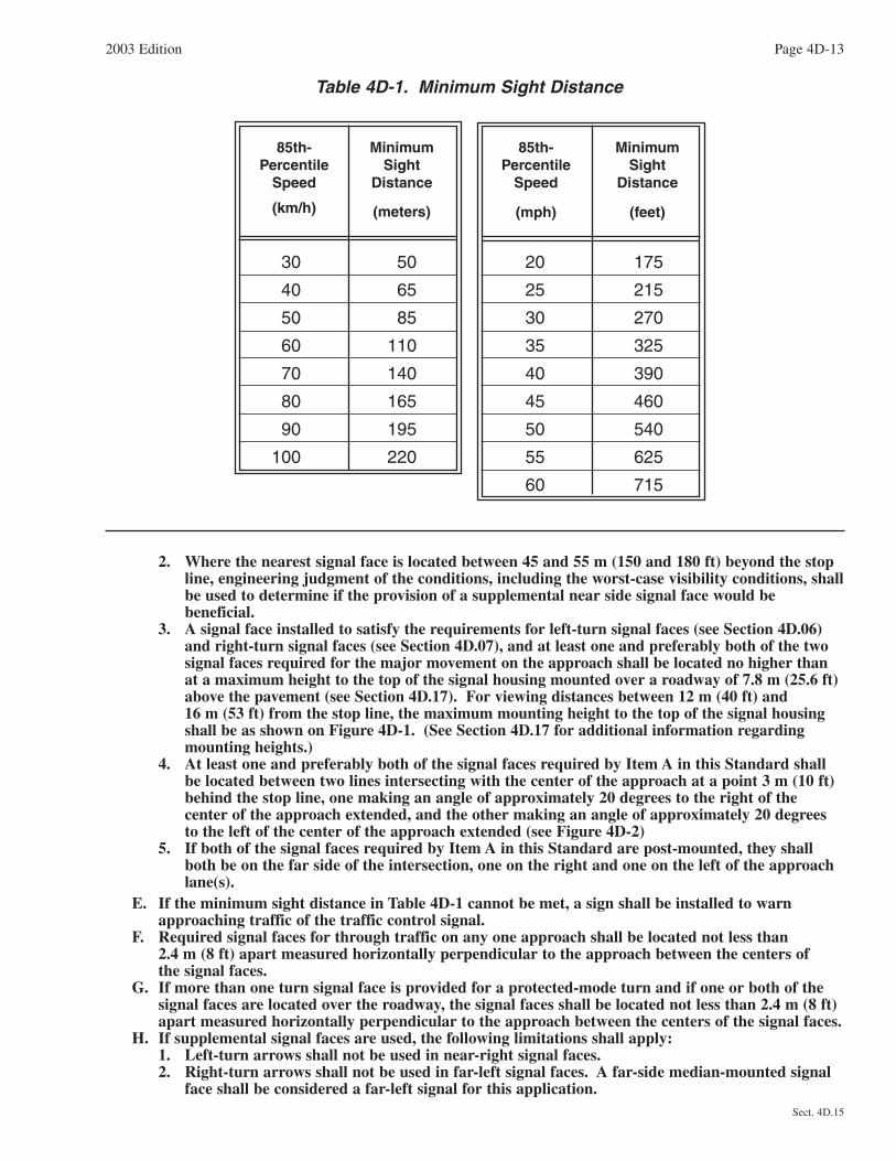
2. Where the nearest signal face is located between 45 and 55 m (150 and 180 ft) beyond the stopline, engineering judgment of the conditions, including the worst-case visibility conditions, shallbe used to determine if the provision of a supplemental near side signal face would bebeneficial.
3. A signal face installed to satisfy the requirements for left-turn signal faces (see Section 4D.06)and right-turn signal faces (see Section 4D.07), and at least one and preferably both of the twosignal faces required for the major movement on the approach shall be located no higher thanat a maximum height to the top of the signal housing mounted over a roadway of 7.8 m (25.6 ft)above the pavement (see Section 4D.17). For viewing distances between 12 m (40 ft) and 16 m (53 ft) from the stop line, the maximum mounting height to the top of the signal housingshall be as shown on Figure 4D-1. (See Section 4D.17 for additional information regardingmounting heights.)
4. At least one and preferably both of the signal faces required by Item A in this Standard shallbe located between two lines intersecting with the center of the approach at a point 3 m (10 ft)behind the stop line, one making an angle of approximately 20 degrees to the right of thecenter of the approach extended, and the other making an angle of approximately 20 degreesto the left of the center of the approach extended (see Figure 4D-2)
5. If both of the signal faces required by Item A in this Standard are post-mounted, they shallboth be on the far side of the intersection, one on the right and one on the left of the approachlane(s).
E. If the minimum sight distance in Table 4D-1 cannot be met, a sign shall be installed to warnapproaching traffic of the traffic control signal.
F. Required signal faces for through traffic on any one approach shall be located not less than 2.4 m (8 ft) apart measured horizontally perpendicular to the approach between the centers of the signal faces.
G. If more than one turn signal face is provided for a protected-mode turn and if one or both of thesignal faces are located over the roadway, the signal faces shall be located not less than 2.4 m (8 ft)apart measured horizontally perpendicular to the approach between the centers of the signal faces.
H. If supplemental signal faces are used, the following limitations shall apply:1. Left-turn arrows shall not be used in near-right signal faces.2. Right-turn arrows shall not be used in far-left signal faces. A far-side median-mounted signal
face shall be considered a far-left signal for this application.
2003 Edition Page 4D-13
Sect. 4D.15
Table 4D-1. Minimum Sight Distance
85th-Percentile
Speed
(km/h)
MinimumSight
Distance
(meters)
85th-Percentile
Speed
(mph)
MinimumSight
Distance
(feet)
30
40
50
60
70
80
90
100
50
65
85
110
140
165
195
220
20
25
30
35
40
45
50
55
60
175
215
270
325
390
460
540
625
715

Page 4D-14 2003 Edition
Sect. 4D.15
7.8
Hei
ght t
o To
p of
Sig
nal H
ousi
ngA
bove
Pav
emen
t, M
eter
s 7.6
7.4
7.2
7.0
6.8
6.6
6.4
12.0 12.5 13.0 13.5 14.0 14.5 15.0 15.5 16.0
Horizontal Distance from Stop Line, Meters
25.6
Hei
ght t
o To
p of
Sig
nal H
ousi
ngA
bove
Pav
emen
t, F
eet
25
24
23
22
21
40 41 42 43 44 45 46 47 48 49 50 51 52 53
Horizontal Distance from Stop Line, Feet
Figure 4D-1. Maximum Mounting Height of Signal Faces Located Between12 Meters (40 Feet) and 16 Meters (53 Feet) from Stop Line

2003 Edition Page 4D-15
Sect. 4D.15
55 m****(180 ft)
Location of signal heads within these areas:
200 mm (8 in) or 300 mm (12 in)signal lenses
300 mm (12 in) signal lenses, unlessa near-side signal face is used
300 mm (12 in) signal lenses
45 m***(150 ft)
35 m**(120 ft)
12 m*(40 ft)
3 m (10 ft)
20º20º CENTER OF APPROACH
XX/2
* Minimum distance of signal faces fromstop line.
** Maximum distance from stop line for 200 mm(8 in) signal faces, unless a near-sidesignal face is used.
*** Maximum distance from stop line for 200 mm(8 in) signal faces when near-sidesupplemental signal face is used.
**** Maximum distance from stop line for 300 mm(12 in) signal faces, unless a near-sidesupplemental signal face is used.
Figure 4D-2. Horizontal Location of Signal Faces

Guidance:The two signal faces required for each approach should be continuously visible to traffic approaching the
traffic control signal, from a point at least the minimum sight distance indicated in Table 4D-1 in advance of andmeasured to the stop line. This range of continuous visibility should be provided unless precluded by a physicalobstruction or unless another signalized location is within this range.
If two or more left-turn lanes are provided for a separately controlled protected only mode left-turnmovement, or if a left-turn movement represents the major movement from an approach, two left-turn signalfaces should be provided.
If two or more right-turn lanes are provided for a separately controlled right-turn movement, or if a right-turnmovement represents the major movement from an approach, two right-turn signal faces should be provided.
Near-side signal faces should be located as near as practical to the stop line.If a signal face controls a specific lane or lanes of an approach, its position should make it readily visible to
road users making that movement.Supplemental signal faces should be used if engineering judgment has shown that they are needed to achieve
intersection visibility both in advance and immediately before the signalized location. If supplemental signalfaces are used, they should be located to provide optimum visibility for the movement to be controlled.
At signalized midblock crosswalks, at least one of the signal faces should be over the traveled way for eachapproach.Option:
If a sign is installed to warn approaching road users of the traffic control signal, the sign may besupplemented by a Warning Beacon (see Section 4K.03).
A Warning Beacon used in this manner may be interconnected with the traffic signal controller assembly insuch a manner as to flash yellow during the period when road users passing this beacon at the legal speed for theroadway might encounter a red signal indication (or a queue resulting from the display of the red signalindication) upon arrival at the signalized location.
Section 4D.16 Number and Arrangement of Signal Sections in Vehicular TrafficControl Signal Faces
Standard:Each signal face at a signalized location shall have three, four, or five signal sections.A single-section signal face shall be permitted at a traffic control signal if it consists of a continuously
illuminated GREEN ARROW signal lens that is being used to indicate a continuous movement.Arrows shall be pointed:A. Vertically upward to indicate a straight-through movement;B. Horizontally in the direction of the turn to indicate a turn at approximately or greater than a right
angle; andC. Upward with a slope at an angle approximately equal to that of the turn if the angle of the turn is
substantially less than a right angle.The signal lenses in a signal face shall be arranged in a vertical or horizontal straight line, except that
in a vertical array, signal lenses of the same color may be arranged horizontally adjacent to each other atright angles to the basic straight line arrangement. Such clusters shall be limited to two identical signallenses or to two or three different signal lenses of the same color.
In each signal face, all red signal lenses in vertically arranged signal faces shall be located above, andin horizontally arranged signal faces shall be located to the left, of all yellow and green signal lenses.
If a CIRCULAR YELLOW signal lens is used, it shall be located between the red signal lens or lensesand all other signal lenses.
In vertically arranged signal faces, each YELLOW ARROW signal lens shall be located immediatelyabove the GREEN ARROW signal lens to which it applies. If a dual-arrow signal section (capable ofalternating between the display of a GREEN ARROW and a YELLOW ARROW signal indication) is used,the lenses shall be in the same position relative to other lenses as are the GREEN ARROW signal lenses ina vertically arranged signal face.
In horizontally arranged signal faces, the YELLOW ARROW signal lens shall be located immediatelyto the left of the GREEN ARROW signal lens. If a dual-arrow signal section (capable of alternatingbetween the display of a GREEN ARROW and a YELLOW ARROW signal indication) is used, the dualleft-turn arrow signal lens shall be located immediately to the right of the CIRCULAR YELLOW signal
Page 4D-16 2003 Edition
Sect. 4D.15 to 4D.16

lens, the straight-through GREEN ARROW signal lens shall be located immediately to the right of theCIRCULAR GREEN signal lens, and the dual right-turn arrow signal lens shall be located to the right ofall other signal lenses.
The relative positions of signal lenses within the signal face shall be as follows:A. In a vertically arranged signal face from top to bottom:
CIRCULAR REDLeft-turn RED ARROWRight-turn RED ARROWCIRCULAR YELLOWCIRCULAR GREENStraight-through GREEN ARROWLeft-turn YELLOW ARROWLeft-turn GREEN ARROWRight-turn YELLOW ARROWRight-turn GREEN ARROW
B. In a horizontally arranged signal face from left to right:CIRCULAR REDLeft-turn RED ARROWRight-turn RED ARROWCIRCULAR YELLOWLeft-turn YELLOW ARROWLeft-turn GREEN ARROWCIRCULAR GREENStraight-through GREEN ARROWRight-turn YELLOW ARROWRight-turn GREEN ARROW
C. If adjacent signal indications in a signal face are not identical, their arrangement shall follow ItemsA or B above, as applicable.
Option:In a vertically arranged signal face, identical signal indications may be repeated in adjacent horizontal
locations within the same signal face.Horizontally arranged and vertically arranged signal faces may be used on the same approach provided they
are separated to meet the lateral separation spacing required in Section 4D.15.Support:
Figure 4D-3 illustrates some of the possible arrangements of signal lenses in signal faces.
Section 4D.17 Visibility, Shielding, and Positioning of Signal FacesStandard:
The primary consideration in signal face placement, aiming, and adjustment shall be to optimize thevisibility of signal indications to approaching traffic. Road users approaching a signalized intersection orother signalized area, such as a midblock crosswalk, shall be given a clear and unmistakable indication oftheir right-of-way assignment.
The geometry of each intersection to be signalized, including vertical grades, horizontal curves, andobstructions as well as the lateral and vertical angles of sight toward a signal face, as determined bytypical driver-eye position, shall be considered in determining the vertical, longitudinal, and lateralposition of the signal face.
In cases where irregular street design necessitates placing signal faces for different street approacheswith a comparatively small angle between their respective signal lenses, each signal lens shall, to the extentpractical, be shielded or directed by signal visors, signal louvers, or other means so that an approachingroad user can see only the signal lens(es) controlling the movements on the road user's approach.
The bottom of the signal housing and any related attachments to a vehicular signal face located over aroadway shall be at least 4.6 m (15 ft) above the pavement. The top of the signal housing of a vehicularsignal face located over a roadway shall not be more than 7.8 m (25.6 ft) above the pavement.
Signal visors exceeding 300 mm (12 in) in length shall not be used on free-swinging signal heads.The bottom of the signal housing (including brackets) of a vehicular signal face that is vertically
arranged and not located over a roadway:
2003 Edition Page 4D-17
Sect. 4D.16 to 4D.17

Page 4D-18 2003 Edition
Sect. 4D.17
a. b.
R
Y
G
R
Y
G
R Y G
c.
R
Y
G
d.
R Y G
e.
R
Y
G
R
f.
R Y GR
R
Y
G
G
g.
R Y
G
h.
G
i.R
Y
G
G
j.
R Y
G G
k.R
Y
G
G
G
l.
R Y
G G G
m.R
Y
G
G
Y
n.
R Y
G
G
Y
o.
R
Y
GG
Y
p.
R Y
G GY
q. r. s. t. u.
R
Y
G G
Y R
Y GG Y
R
Y
G
G
Y
R Y
G
G
Y
R
Y
G
R
Figure 4D-3. Typical Arrangements of Signal Lenses in Signal Faces

A. Shall be at least 2.4 m (8 ft) but not more than 5.8 m (19 ft) above the sidewalk or, if there is nosidewalk, above the pavement grade at the center of the roadway.
B. Shall be at least 1.4 m (4.5 ft) but not more than 5.8 m (19 ft) above the median island grade of acenter median island if located on the near side of the intersection.
The bottom of the signal housing (including brackets) of a vehicular signal face that is horizontallyarranged and not located over a roadway:
A. Shall be at least 2.4 m (8 ft) but not more than 6.7 m (22 ft) above the sidewalk or, if there is nosidewalk, above the pavement grade at the center of the roadway.
B. Shall be at least 1.4 m (4.5 ft) but not more than 6.7 m (22 ft) above the median island grade of acenter median island if located on the near side of the intersection.
Signal heads mounted at less than 4.6 meters (15 feet) from the bottom of the housing and any relatedattachments at the side of a roadway with curbs shall have a horizontal clearance of not less than 0.6 m (2 ft) from the face of a vertical curb. If there is no curb, signal heads shall have a horizontal clearance ofnot less than 0.6 m (2 ft) from the edge of a shoulder.Guidance:
There should be legal authority to prohibit the display of any unauthorized sign, signal, marking, or devicethat interferes with the effectiveness of any official traffic control device (see Section 11-205 of the “UniformVehicle Code”).
Signal visors should be used on signal faces to aid in directing the signal indication specifically toapproaching traffic, as well as to reduce “sun phantom,” which can result when external light enters the lens.
The use of signal visors, or the use of signal faces or devices that direct the light without a reduction inintensity, should be considered as an alternative to signal louvers because of the reduction in light output causedby signal louvers.
The use of a signal backplate for target value enhancement should be considered on signal faces viewedagainst a bright sky or bright or confusing backgrounds.Support:
The use of backplates enhances the contrast between the traffic signal indications and their surroundings forboth day and night conditions, which is also helpful to elderly drivers.Option:
Special signal faces, such as visibility-limited signal faces, may be used such that the road user does not seesignal indications intended for other approaches before seeing the signal indications for their own approach, ifsimultaneous viewing of both signal indications could cause the road user to be misdirected.
If the sight distance to the signal heads facing the approach is limited by horizontal or vertical alignment,supplemental signal faces aimed at a point on the approach at which the signal indications first become visiblemay be used.
Section 4D.18 Design, Illumination, and Color of Signal SectionsStandard:
Each signal indication, except those used for pedestrian signal heads and lane-use control signals, shallbe circular or arrow.
Letters or numbers shall not be displayed as part of a vehicular signal indication.Each signal indication shall be independently illuminated.Each circular signal indication shall emit a single color: red, yellow, or green.Each arrow signal indication shall emit a single color: red, yellow, or green except that the alternate
display (dual-arrow signal section) of a GREEN ARROW and a YELLOW ARROW signal indication, bothpointing in the same direction, shall be permitted, provided that they are not displayed simultaneously.
The arrow, which shall show only one direction, shall be the only illuminated part of an arrow signalindication.
Except for the requirements of this section, the requirements of the “Standards for Vehicle TrafficControl Signal Heads” (see Section 1A.11) shall be met.
References to signal lenses in this section shall not be used to limit signal optical units to incandescentlamps within optical assemblies that include lenses.
2003 Edition Page 4D-19
Sect. 4D.17 to 4D.18

Support:Research has resulted in signal optical units that are not lenses, such as, but not limited to, light-emitting
diode (LED) traffic signal modules. Some units are practical for all signal indications, and some are practical forspecific types such as visibility-limited signal indications.Guidance:
The intensity and distribution of light from each illuminated signal lens should conform to the current“Standards for Vehicle Traffic Control Signal Heads” and “Traffic Signal Lamps” (see Section 1A.11).
If a signal indication is operated in the flashing mode for nighttime operation and the signal indication is sobright as to cause excessive glare, some form of automatic dimming should be used to reduce the brilliance ofthe signal indication.Standard:
The inside of signal visors (hoods), the entire surface of louvers and fins, and the front surface ofbackplates shall have a dull black finish to minimize light reflection and to increase contrast between thesignal indication and its background.
Section 4D.19 Lateral Placement of Signal Supports and CabinetsGuidance:
The following items should be considered when placing signal supports and cabinets:A. Reference should be made to the American Association of State Highway and Transportation Officials
(AASHTO) “Roadside Design Guide” (see Section 1A.11) and to the “Americans with Disabilities ActAccessibility Guidelines for Buildings and Facilities (ADAAG)” (see Section 1A.11).
B. Signal supports should be placed as far as practical from the edge of the traveled way without adverselyaffecting the visibility of the signal indications.
Where supports cannot be located based on the recommended AASHTO clearances, considerationshould be given to the use of appropriate safety devices.
No part of a concrete base for a signal support should extend more than 100 mm (4 in) above theground level at any point. This limitation does not apply to the concrete base for a rigid support.
C. In order to minimize hindrance to the passage of persons with physical disabilities, a signal support orcontroller cabinet should not obstruct the sidewalk, or access from the sidewalk to the crosswalk.
D. Controller cabinets should be located as far as practical from the edge of the roadway.E. On medians, the above minimum clearances for signal supports should be obtained if practical.
Section 4D.20 Temporary Traffic Control SignalsStandard:
A temporary traffic control signal shall be defined as a traffic control signal that is installed for alimited time period. A portable traffic control signal shall be defined as a temporary traffic control signalthat is designed so that it can be easily transported and reused at different locations.Support:
A temporary traffic control signal is generally installed using methods that minimize the costs of installation,relocation, and/or removal. Typical temporary traffic control signals are for specific purposes, such as for one-lane, two-way facilities in temporary traffic control zones (see Chapter 4G), for a haul-road intersection, or foraccess to a site that will have a permanent access point developed at another location in the near future.Standard:
Advance signing shall be used when employing a temporary traffic control signal.A temporary traffic control signal shall:A. Meet the physical display and operational requirements of a conventional traffic control signal.B. Be removed when no longer needed.C. Be placed in the flashing mode when not being used if it will be operated in the steady mode within
5 working days; otherwise, it shall be removed.D. Be placed in the flashing mode during periods when it is not desirable to operate the signal, or the
signal heads shall be covered, turned, or taken down to indicate that the signal is not in operation.
Page 4D-20 2003 Edition
Sect. 4D.18 to 4D.20

Guidance:A temporary traffic control signal should be used only if engineering judgment indicates that installing the
signal will improve the overall safety and/or operation of the location. The use of temporary traffic controlsignals by a work crew on a regular basis in their work area should be subject to the approval of the jurisdictionhaving authority over the roadway.
A temporary traffic control signal should not operate longer than 30 days unless associated with a longer-term temporary traffic control zone project.
For use of temporary traffic control signals in temporary traffic control zones, reference should be made toSection 6F.80.
Section 4D.21 Traffic Signal Signs, AuxiliarySupport:
Traffic signal signs are sometimes used at highway traffic signal locations to instruct or guide pedestrians,bicyclists, or motorists.Standard:
The minimum vertical and horizontal clearance of the total assembly of traffic signal signs (see Section 2B.45) shall conform to the provisions of Section 4D.17.
If used, illuminated traffic signal signs shall be designed and mounted in such a manner as to avoidglare and reflections that seriously detract from the signal indications. Traffic control signal faces shall be given dominant position and brightness to maximize their priority in the overall display.Guidance:
Traffic signal signs should be located adjacent to the signal face to which they apply.
2003 Edition Page 4D-21
Sect. 4D.20 to 4D.21

CHAPTER 4E. PEDESTRIAN CONTROL FEATURES
Section 4E.01 Pedestrian Signal HeadsSupport:
Pedestrian signal heads provide special types of traffic signal indications exclusively intended for controllingpedestrian traffic. These signal indications consist of the illuminated symbols of a WALKING PERSON(symbolizing WALK) and an UPRAISED HAND (symbolizing DONT WALK).Guidance:
Engineering judgment should determine the need for separate pedestrian signal heads (see Section 4D.03)and accessible pedestrian signals (see Section 4E.06).
Section 4E.02 Meaning of Pedestrian Signal Head IndicationsStandard:
Pedestrian signal head indications shall have the following meanings:A. A steady WALKING PERSON (symbolizing WALK) signal indication means that a pedestrian
facing the signal indication is permitted to start to cross the roadway in the direction of the signalindication, possibly in conflict with turning vehicles. The pedestrian shall yield the right-of-way tovehicles lawfully within the intersection at the time that the WALKING PERSON (symbolizingWALK) signal indication is first shown.
B. A flashing UPRAISED HAND (symbolizing DONT WALK) signal indication means that apedestrian shall not start to cross the roadway in the direction of the signal indication, but that anypedestrian who has already started to cross on a steady WALKING PERSON (symbolizing WALK)signal indication shall proceed out of the traveled way.
C. A steady UPRAISED HAND (symbolizing DONT WALK) signal indication means that apedestrian shall not enter the roadway in the direction of the signal indication.
D. A flashing WALKING PERSON (symbolizing WALK) signal indication has no meaning and shallnot be used.
Section 4E.03 Application of Pedestrian Signal HeadsStandard:
Pedestrian signal heads shall be used in conjunction with vehicular traffic control signals under any ofthe following conditions:
A. If a traffic control signal is justified by an engineering study and meets either Warrant 4,Pedestrian Volume or Warrant 5, School Crossing (see Chapter 4C);
B. If an exclusive signal phase is provided or made available for pedestrian movements in one or moredirections, with all conflicting vehicular movements being stopped; or
C. At an established school crossing at any signalized location.D. Where engineering judgment determines that multiphase signal indications (as with split-phase
timing) would tend to confuse or cause conflicts with pedestrians using a crosswalk guided only byvehicular signal indications.
Guidance:Pedestrian signal heads should be used under any of the following conditions:A. If it is necessary to assist pedestrians in making a reasonably safe crossing or if engineering judgment
determines that pedestrian signal heads are justified to minimize vehicle-pedestrian conflicts;B. If pedestrians are permitted to cross a portion of a street, such as to or from a median of sufficient width
for pedestrians to wait, during a particular interval but are not permitted to cross the remainder of thestreet during any part of the same interval; and/or
C. If no vehicular signal indications are visible to pedestrians, or if the vehicular signal indications that arevisible to pedestrians starting or continuing a crossing provide insufficient guidance for them to decidewhen it is reasonably safe to cross, such as on one-way streets, at T-intersections, or at multiphase signaloperations.
Section 4E.04 Size, Design, and Illumination of Pedestrian Signal Head IndicationsStandard:
All new pedestrian signal head indications shall be displayed within a rectangular background and shallconsist of symbolized messages (see Figure 4E-1), except that existing pedestrian signal head indicationswith lettered or outline style symbol messages may be retained for the remainder of their useful
2003 Edition Page 4E-1
Sect. 4E.01 to 4E.04

Page 4E-2 2003 Edition
Sect. 4E.04
Figure 4E-1. Typical Pedestrian Signal Indications
One Section
Two Section
service life. The symbol designs that are set forth in the “Standard Highway Signs” book shall be used.Each pedestrian signal head indication shall be independently illuminated and emit a single color.
The UPRAISED HAND (symbolizing DONT WALK) signal section shall be mounted directly above orintegral with the WALKING PERSON (symbolizing WALK) signal section.
The WALKING PERSON (symbolizing WALK) signal indication shall be white, conforming to thepublication entitled “Pedestrian Traffic Control Signal Indications” (see Section 1A.11), with all except thesymbol obscured by an opaque material.
The UPRAISED HAND (symbolizing DONT WALK) signal indication shall be Portland orange,conforming to the publication entitled “Pedestrian Traffic Control Signal Indications” (see Section 1A.11),with all except the symbol obscured by an opaque material.
When not illuminated, the WALKING PERSON (symbolizing WALK) and UPRAISED HAND(symbolizing DONT WALK) symbols shall not be readily visible to pedestrians at the far end of thecrosswalk that the pedestrian signal head indications control.
For pedestrian signal head indications, the symbols shall be at least 150 mm (6 in) high.The light source of a flashing UPRAISED HAND (symbolizing DONT WALK) signal indication shall
be flashed continuously at a rate of not less than 50 nor more than 60 times per minute. The illuminatedperiod of each flash shall be not less than half and not more than two-thirds of the total flash cycle.Guidance:
Pedestrian signal head indications should be conspicuous and recognizable to pedestrians at all distancesfrom the beginning of the controlled crosswalk to a point 3 m (10 ft) from the end of the controlled crosswalkduring both day and night.
For crosswalks where the pedestrian enters the crosswalk more than 30 m (100 ft) from the pedestrian signalhead indications, the symbols should be at least 225 mm (9 in) high.Option:
An animated eyes symbol may be added to a pedestrian signal head in order to prompt pedestrians to lookfor vehicles in the intersection during the time that the WALK signal indication is displayed.Standard:
If used, the animated eyes symbol shall consist of an outline of a pair of white steadily-illuminated eyeswith white eyeballs that scan from side to side at a rate of approximately once per second. The animatedeyes symbol shall be at least 300 mm (12 in) wide with each eye having a width of at least 125 mm (5 in)and a height of at least 62 mm (2.5 in). The animated eyes symbol shall be illuminated at the start of thewalk interval and shall terminate at the end of the walk interval.
Section 4E.05 Location and Height of Pedestrian Signal HeadsStandard:
Pedestrian signal heads shall be mounted with the bottom of the signal housing including brackets notless than 2.1 m (7 ft) nor more than 3 m (10 ft) above sidewalk level, and shall be positioned and adjustedto provide maximum visibility at the beginning of the controlled crosswalk.
If pedestrian signal heads are mounted on the same support as vehicular signal heads, there shall be aphysical separation between them.
Section 4E.06 Accessible Pedestrian SignalsSupport:
The primary technique that pedestrians who have visual disabilities use to cross streets at signalized locationsis to initiate their crossing when they hear the traffic in front of them stop and the traffic alongside them begin tomove, corresponding to the onset of the green interval. This technique is effective at many signalized locations.The existing environment is often sufficient to provide the information that pedestrians who have visualdisabilities need to operate reasonably safely at a signalized location. Therefore, many signalized locations willnot require any accessible pedestrian signals.Guidance:
If a particular signalized location presents difficulties for pedestrians who have visual disabilities to crossreasonably safely and effectively, an engineering study should be conducted that considers the safety andeffectiveness for pedestrians in general, as well as the information needs of pedestrians with visual disabilities.
2003 Edition Page 4E-3
Sect. 4E.04 to 4E.06

Support:The factors that might make crossing at a signalized location difficult for pedestrians who have visual
disabilities include: increasingly quiet cars, right turn on red (which masks the beginning of the through phase),continuous right-turn movements, complex signal operations, traffic circles, and wide streets. Further, low trafficvolumes might make it difficult for pedestrians who have visual disabilities to discern signal phase changes.
Local organizations, providing support services to pedestrians who have visual and/or hearing disabilities,can often act as important advisors to the traffic engineer when consideration is being given to the installation ofdevices to assist such pedestrians. Additionally, orientation and mobility specialists or similar staff also might beable to provide a wide range of advice. The U.S. Access Board’s Document A-37, “Accessible PedestrianSignals,” provides various techniques for making pedestrian signal information available to persons with visualdisabilities (see Page i for the address for the U.S. Access Board).
Accessible pedestrian signals provide information in nonvisual format (such as audible tones, verbalmessages, and/or vibrating surfaces).
Information regarding detectors for accessible pedestrian signals is found in Section 4E.09.Standard:
When used, accessible pedestrian signals shall be used in combination with pedestrian signal timing.The information provided by an accessible pedestrian signal shall clearly indicate which pedestriancrossing is served by each device.
Under stop-and-go operation, accessible pedestrian signals shall not be limited in operation by the time of day or day of week.Guidance:
The installation of accessible pedestrian signals at signalized locations should be based on an engineeringstudy, which should consider the following factors:
A. Potential demand for accessible pedestrian signals;B. A request for accessible pedestrian signals;C. Traffic volumes during times when pedestrians might be present, including periods of low traffic
volumes or high turn-on-red volumes;D. The complexity of traffic signal phasing; andE. The complexity of intersection geometry.
Support:Technology that provides different sounds for each nonconcurrent signal phase has frequently been found to
provide ambiguous information.Standard:
When choosing audible tones, possible extraneous sources of sounds (such as wind, rain, vehicle back-up warnings, or birds) shall be considered in order to eliminate potential confusion to pedestrians whohave visual disabilities.Guidance:
Audible pedestrian tones should be carefully selected to avoid misleading pedestrians who have visualdisabilities when the following conditions exist:
A. Where there is an island that allows unsignalized right turns across a crosswalk between the island andthe sidewalk.
B. Where multileg approaches or complex signal phasing require more than two pedestrian phases, such thatit might be unclear which crosswalk is served by each audible tone.
C. At intersections where a diagonal pedestrian crossing is allowed, or where one street receives aWALKING PERSON (symbolizing WALK) signal indication simultaneously with another street.
Standard:When accessible pedestrian signals have an audible tone(s), they shall have a tone for the walk interval.
The audible tone(s) shall be audible from the beginning of the associated crosswalk. If the tone for thewalk interval is similar to the pushbutton locator tone, the walk interval tone shall have a faster repetitionrate than the associated pushbutton locator tone.Support:
A pushbutton locator tone is a repeating sound that informs approaching pedestrians that they are required to push a button to actuate pedestrian timing, and that enables visually impaired pedestrians to locate thepushbutton (see Section 4E.09).
Page 4E-4 2003 Edition
Sect. 4E.06

Guidance:The accessible walk signal tone should be no louder than the locator tone, except when there is optional
activation to provide a louder signal tone for a single pedestrian phase.Automatic volume adjustment in response to ambient traffic sound level should be provided up to a
maximum volume of 89 dBA. Where automatic volume adjustment is used, tones should be no more than 5 dBAlouder than ambient sound. The A-weighted sound pressure level should conform to the requirements of “ISO1996-1:1982” and “ISO 1996-2:1987” (see Page i for the address for the International Organization forStandards).Standard:
When verbal messages are used to communicate the pedestrian interval, they shall provide a clearmessage that the walk interval is in effect, as well as to which crossing it applies.
The verbal message that is provided at regular intervals throughout the timing of the walk intervalshall be the term “walk sign,” which may be followed by the name of the street to be crossed.
A verbal message is not required at times when the walk interval is not timing, but, if provided:A. It shall be the term “wait.”B. It need not be repeated for the entire time that the walk interval is not timing.
Option:Accessible pedestrian signals that provide verbal messages may provide similar messages in languages other
than English, if needed, except for the terms “walk sign” and “wait.”Support:
A vibrotactile pedestrian device communicates information about pedestrian timing through a vibratingsurface by touch.Standard:
Vibrotactile pedestrian devices, where used, shall indicate that the walk interval is in effect, and forwhich direction it applies, through the use of a vibrating directional arrow or some other means.Guidance:
When provided, vibrotactile pedestrian devices should be located next to, and on the same pole as, thepedestrian pushbutton, if any, and adjacent to the intended crosswalk.
Section 4E.07 Countdown Pedestrian SignalsOption:
A pedestrian interval countdown display may be added to a pedestrian signal head in order to informpedestrians of the number of seconds remaining in the pedestrian change interval.Standard:
If used, countdown pedestrian signals shall consist of Portland orange numbers that are at least 150 mm(6 in) in height on a black opaque background. The countdown pedestrian signal shall be locatedimmediately adjacent to the associated UPRAISED HAND (symbolizing DONT WALK) pedestrian signalhead indication.
If used, the display of the number of remaining seconds shall begin only at the beginning of thepedestrian change interval. After the countdown displays zero, the display shall remain dark until thebeginning of the next countdown.
If used, the countdown pedestrian signal shall display the number of seconds remaining until thetermination of the pedestrian change interval. Countdown displays shall not be used during the walkinterval nor during the yellow change interval of a concurrent vehicular phase.Guidance:
If used with a pedestrian signal head that does not have a concurrent vehicular phase, the pedestrian changeinterval (flashing UPRAISED HAND) should be set to be approximately 4 seconds less than the requiredpedestrian crossing time (see Section 4E.10) and an additional clearance interval (during which steadyUPRAISED HAND is displayed) should be provided prior to the start of the conflicting vehicular phase. In thiscase, the countdown display of the number of remaining seconds should be displayed only during the display ofthe flashing UPRAISED HAND, should display zero at the time when the flashing UPRAISED HAND changesto steady UPRAISED HAND, and should be dark during the additional clearance interval prior to the conflictingvehicular phase.
2003 Edition Page 4E-5
Sect. 4E.06 to 4E.07
For crosswalks where the pedestrian enters the crosswalk more than 30 m (100 ft) from the countdownpedestrian signal display, the numbers should be at least 225 mm (9 in) in height.
Because some technology includes the countdown pedestrian signal logic in a separate timing device that isindependent of the timing in the traffic signal controller, care should be exercised by the engineer when timingchanges are made to pedestrian change intervals.
If the pedestrian change interval is interrupted or shortened as a part of a transition into a preemptionsequence (see Section 4E.10), the countdown pedestrian signal display should be discontinued and go darkimmediately upon activation of the preemption transition.
Section 4E.08 Pedestrian DetectorsGuidance:
When pedestrian actuation is used, pedestrian pushbutton detectors should be capable of easy activation andconveniently located near each end of the crosswalks.Standard:
Signs (see Section 2B.44) shall be mounted adjacent to or integral with pedestrian pushbuttondetectors, explaining their purpose and use.Option:
At certain locations, a sign in a more visible location may be used to call attention to the pedestrian detector.Guidance:
If two crosswalks, oriented in different directions, end at or near the same location, the positioning ofpedestrian detectors and/or the legends on the pedestrian detector signs should clearly indicate which crosswalksignal is actuated by each pedestrian detector.Standard:
If the pedestrian clearance time is sufficient only to cross from the curb or shoulder to a median ofsufficient width for pedestrians to wait and the signals are pedestrian actuated, an additional pedestriandetector shall be provided in the median.Guidance:
The use of additional pedestrian detectors on islands or medians where a pedestrian might become strandedshould be considered.
A mounting height of approximately 1.1 m (3.5 ft) above the sidewalk should be used for pedestrianpushbutton detectors.
If used, special purpose pushbuttons (to be operated only by authorized persons) should include a housingcapable of being locked to prevent access by the general public and do not need an instructional sign.Standard:
If used, a pilot light or other means of indication installed with a pedestrian pushbutton shall not beilluminated until actuation. Once it is actuated, it shall remain illuminated until the pedestrian’s green orWALKING PERSON (symbolizing WALK) signal indication is displayed.Option:
At signalized locations with a demonstrated need and subject to equipment capabilities, pedestrians withspecial needs may be provided with additional crossing time by means of an extended pushbutton press.
Section 4E.09 Accessible Pedestrian Signal DetectorsStandard:
An accessible pedestrian signal detector shall be defined as a device designated to assist the pedestrianwho has visual or physical disabilities in activating the pedestrian phase.
At accessible pedestrian signal locations with pedestrian actuation, each pushbutton shall activate boththe walk interval and the accessible pedestrian signals.Option:
Accessible pedestrian signal detectors may be pushbuttons or passive detection devices.Pushbutton locator tones may be used with accessible pedestrian signals.
Guidance:At accessible pedestrian signal locations, pushbuttons should clearly indicate which crosswalk signal is
actuated by each pushbutton. Pushbuttons and tactile arrows should have high visual contrast as described in the
Page 4E-6 2003 Edition
Sect. 4E.07 to 4E.09

“Americans with Disabilities Act Accessibility Guidelines for Buildings and Facilities (ADAAG)” (see Section1A.11). Tactile arrows should point in the same direction as the associated crosswalk. At corners of signalizedlocations with accessible pedestrian signals where two pedestrian pushbuttons are provided, the pushbuttonsshould be separated by a distance of at least 3 m (10 ft). This enables pedestrians who have visual disabilities to distinguish and locate the appropriate pushbutton.
Pushbuttons for accessible pedestrian signals should be located (see Figure 4E-2) as follows:A. Adjacent to a level all-weather surface to provide access from a wheelchair, and where there is an
all-weather surface, wheelchair accessible route to the ramp;B. Within 1.5 m (5 ft) of the crosswalk extended;C. Within 3 m (10 ft) of the edge of the curb, shoulder, or pavement; andD. Parallel to the crosswalk to be used.If the pedestrian clearance time is sufficient only to cross from the curb or shoulder to a median of sufficient
width for pedestrians to wait and accessible pedestrian detectors are used, an additional accessible pedestriandetector should be provided in the median.Standard:
When used, pushbutton locator tones shall be easily locatable, shall have a duration of 0.15 seconds or less, and shall repeat at 1-second intervals.Guidance:
Pushbuttons should be audibly locatable. Pushbutton locator tones should be intensity responsive to ambientsound, and be audible 1.8 to 3.7 m (6 to 12 ft) from the pushbutton, or to the building line, whichever is less.Pushbutton locator tones should be no more than 5 dBA louder than ambient sound.
Pushbutton locator tones should be deactivated during flashing operation of the traffic control signal.Option:
At locations with pretimed traffic control signals or nonactuated approaches, pedestrian pushbuttons may beused to activate the accessible pedestrian signals.
The audible tone(s) may be made louder (up to a maximum of 89 dBA) by holding down the pushbutton fora minimum of 3 seconds. The louder audible tone(s) may also alternate back and forth across the crosswalk, thusproviding optimal directional information.
The name of the street to be crossed may also be provided in accessible format, such as Braille or raisedprint.
Section 4E.10 Pedestrian Intervals and Signal PhasesStandard:
When pedestrian signal heads are used, a WALKING PERSON (symbolizing WALK) signal indicationshall be displayed only when pedestrians are permitted to leave the curb or shoulder.
A pedestrian clearance time shall begin immediately following the WALKING PERSON (symbolizingWALK) signal indication. The first portion of the pedestrian clearance time shall consist of a pedestrianchange interval during which a flashing UPRAISED HAND (symbolizing DONT WALK) signal indicationshall be displayed. The remaining portions shall consist of the yellow change interval and any redclearance interval (prior to a conflicting green being displayed), during which a flashing or steadyUPRAISED HAND (symbolizing DONT WALK) signal indication shall be displayed.
If countdown pedestrian signals are used, a steady UPRAISED HAND (symbolizing DONT WALK)signal indication shall be displayed during the yellow change interval and any red clearance interval (prior to a conflicting green being displayed) (see Section 4E.07).
At intersections equipped with pedestrian signal heads, the pedestrian signal indications shall bedisplayed except when the vehicular traffic control signal is being operated in the flashing mode. At thosetimes, the pedestrian signal lenses shall not be illuminated.Guidance:
Except as noted in the Option, the walk interval should be at least 7 seconds in length so that pedestrians willhave adequate opportunity to leave the curb or shoulder before the pedestrian clearance time begins.Option:
If pedestrian volumes and characteristics do not require a 7-second walk interval, walk intervals as short as 4 seconds may be used.
2003 Edition Page 4E-7
Sect. 4E.09 to 4E.10

Page 4E-8 2003 Edition
Sect. 4E.10
1.5 m (5 ft)MAX.
3 m (10 ft) MAX.
3 m (1
0 ft)
MIN.
Two Curb-Cut Ramps
1.5 m (5 ft)MAX.
3 m (10 ft) MAX.
3 m
(10
ft) M
IN.
One Curb-Cut Ramp
Legend
Pedestrian Pushbutton
Figure 4E-2. Recommended Pushbutton Locationsfor Accessible Pedestrian Signals
Support:The walk interval itself need not equal or exceed the pedestrian clearance time calculated for the roadway
width, because many pedestrians will complete their crossing during the pedestrian clearance time.Guidance:
The pedestrian clearance time should be sufficient to allow a pedestrian crossing in the crosswalk who leftthe curb or shoulder during the WALKING PERSON (symbolizing WALK) signal indication to travel at awalking speed of 1.2 m (4 ft) per second, to at least the far side of the traveled way or to a median of sufficientwidth for pedestrians to wait. Where pedestrians who walk slower than 1.2 m (4 ft) per second, or pedestrianswho use wheelchairs, routinely use the crosswalk, a walking speed of less than 1.2 m (4 ft) per second should be considered in determining the pedestrian clearance time.Option:
Passive pedestrian detection equipment, which can detect pedestrians who need more time to complete theircrossing and can extend the length of the pedestrian clearance time for that particular cycle, may be used in orderto avoid using a lower walking speed to determine the pedestrian clearance time.Guidance:
Where the pedestrian clearance time is sufficient only for crossing from the curb or shoulder to a median ofsufficient width for pedestrians to wait, additional measures should be considered, such as median-mountedpedestrian signals or additional signing.Option:
The pedestrian clearance time may be entirely contained within the vehicular green interval, or may beentirely contained within the vehicular green and yellow change intervals.
On a street with a median of sufficient width for pedestrians to wait, a pedestrian clearance time that allowsthe pedestrian to cross only from the curb or shoulder to the median may be provided.
During the transition into preemption, the walk interval and the pedestrian change interval may be shortenedor omitted as described in Section 4D.13.
2003 Edition Page 4E-9
Sect. 4E.10


CHAPTER 4F. TRAFFIC CONTROL SIGNALS FOR EMERGENCY VEHICLE ACCESS
Section 4F.01 Applications of Emergency-Vehicle Traffic Control SignalsSupport:
An emergency-vehicle traffic control signal is a special traffic control signal that assigns the right-of-way toan authorized emergency vehicle.Option:
An emergency-vehicle traffic control signal may be installed at a location that does not meet other trafficsignal warrants such as at an intersection or other location to permit direct access from a building housing theemergency vehicle.Guidance:
If a traffic control signal is not justified under the signal warrants of Chapter 4C and if gaps in traffic are notadequate to permit reasonably safe entrance of emergency vehicles, or the stopping sight distance for vehiclesapproaching on the major street is insufficient to permit reasonably safe entrance of emergency vehicles,installing an emergency-vehicle traffic control signal should be considered. If one of the signal warrants ofChapter 4C is met and a traffic control signal is justified by an engineering study, and if a decision is made toinstall a traffic control signal, it should be installed based upon the provisions of Chapter 4D.
The sight distance determination should be based on the location of the visibility obstruction for the criticalapproach lane for each street or drive and the posted or statutory speed limit or 85th-percentile speed on themajor street, whichever is higher.
Section 4F.02 Design of Emergency-Vehicle Traffic Control SignalsStandard:
Except as specified in this Section, an emergency-vehicle traffic control signal shall meet therequirements of this Manual.
An Emergency Vehicle (W11-8) sign (see Section 2C.40) with an EMERGENCY SIGNAL AHEAD(W11-12p) supplemental plaque shall be placed in advance of all emergency-vehicle traffic control signals.If a warning beacon is installed to supplement the W11-8 sign, the design and location of the beacon shallconform to the Standards specified in Sections 4K.01 and 4K.03.Guidance:
At least one of the two required signal faces for each approach on the major street should be located over theroadway.
The following size signal lenses should be used for emergency-vehicle traffic control signals: 300 mm (12in) diameter for red and steady yellow signal indications, and 200 mm (8 in) diameter for flashing yellow orsteady green signal indications.Standard:
An EMERGENCY SIGNAL (R10-13) sign shall be mounted adjacent to a signal face on each majorstreet approach (see Section 2B.45). If an overhead signal face is provided, the EMERGENCY SIGNALsign shall be mounted adjacent to the overhead signal face.Option:
An approach that only serves emergency vehicles may be provided with only one signal face consisting ofone or more signal sections.
Besides using a 200 mm (8 in) diameter signal indication, other appropriate means to reduce the flashingyellow light output may be used.
Section 4F.03 Operation of Emergency-Vehicle Traffic Control SignalsStandard:
Right-of-way for emergency vehicles at signalized locations operating in the steady (stop-and-go) modeshall be obtained as specified in Section 4D.13.
As a minimum, the signal indications, sequence, and manner of operation of an emergency-vehicletraffic control signal installed at a midblock location shall be as follows:
2003 Edition Page 4F-1
Sect. 4F.01 to 4F.03

A. The signal indication, between emergency-vehicle actuations, shall be either steady green orflashing yellow. If the flashing yellow signal indication is used instead of the steady green signalindication, it shall be displayed in the normal position of the steady green signal indication, whilethe red and steady yellow signal indications shall be displayed in their normal positions.
B. When an emergency vehicle actuation occurs, a steady yellow change interval followed by a steadyred interval shall be displayed to traffic on the major street.
C. A yellow change interval is not required following the green interval for the emergency-vehicledriveway.
Emergency-vehicle traffic control signals located at intersections shall either be operated in theflashing mode between emergency-vehicle actuations (see Section 4D.12) or be fully or semi-traffic-actuated, to accommodate normal vehicular and pedestrian traffic on the streets.
Warning beacons, if used with an emergency-vehicle traffic control signal, shall be flashed only:A. For an appropriate time in advance of and during the steady yellow change interval for the major
street; andB. During the steady red interval for the major street.
Guidance:The duration of the red interval for traffic on the major street should be determined by on-site test-run time
studies, but should not exceed 1.5 times the time required for the emergency vehicle to clear the path ofconflicting vehicles.Option:
An emergency-vehicle traffic control signal sequence may be initiated manually from a local control pointsuch as a fire station or law enforcement headquarters or from an emergency vehicle equipped for remoteoperation of the signal.
Page 4F-2 2003 Edition
Sect. 4F.03

CHAPTER 4G. TRAFFIC CONTROL SIGNALS FOR ONE-LANE, TWO-WAY FACILITIES
Section 4G.01 Application of Traffic Control Signals for One-Lane, Two-Way FacilitiesSupport:
A traffic control signal at a narrow bridge, tunnel, or roadway section is a special signal that assigns theright-of-way for vehicles passing over a bridge or through a tunnel or roadway section that is not of sufficientwidth for two opposing vehicles to pass reasonably safely.
Temporary traffic control signals (see Sections 4D.20 and 6F.80) are the most frequent application of one-lane, two-way facilities.Guidance:
Sight distance across or through the one-lane, two-way facility should be considered as well as the approachspeed and sight distance approaching the facility when determining whether traffic control signals should beinstalled.Option:
At a narrow bridge, tunnel, or roadway section where a traffic control signal is not justified under theconditions of Chapter 4C, a traffic control signal may be used if gaps in opposing traffic do not permit thereasonably safe flow of traffic through the one-lane section of roadway.
Section 4G.02 Design of Traffic Control Signals for One-Lane, Two-Way FacilitiesStandard:
The provisions of Chapter 4D shall apply to traffic control signals for one-lane, two-way facilities,except that:
A. Durations of red clearance intervals shall be adequate to clear the one-lane section of conflictingvehicles.
B. Adequate means, such as interconnection, shall be provided to prevent conflicting signalindications, such as green and green, at opposite ends of the section.
Section 4G.03 Operation of Traffic Control Signals for One-Lane, Two-Way FacilitiesStandard:
Traffic control signals at one-lane, two-way facilities shall operate in a manner consistent with trafficrequirements.
When in the flashing mode, the signal indications shall flash red.Guidance:
Adequate time should be provided to allow traffic to clear the narrow facility before opposing traffic isallowed to move. Engineering judgment should be used to determine the proper timing for the signal.
2003 Edition Page 4G-1
Sect. 4G.01 to 4G.03

CHAPTER 4H. TRAFFIC CONTROL SIGNALS FOR FREEWAY ENTRANCE RAMPS
Section 4H.01 Application of Freeway Entrance Ramp Control SignalsSupport:
Ramp control signals are traffic control signals that control the flow of traffic entering the freeway facility.Freeway entrance ramp control signals are sometimes used if controlling traffic entering the freeway could
reduce the total expected delay to traffic in the freeway corridor, including freeway ramps and local streets, and if at least one of the following conditions is present:
A. Congestion recurs on the freeway because traffic demand is in excess of the capacity, or congestionrecurs or a high frequency of crashes exist at the freeway entrance because of inadequate ramp mergingarea. A good indicator of recurring freeway congestion is freeway operating speeds less than 80 km/h(50 mph) occurring regularly for at least a half-hour period. Freeway operating speeds less than 50 km/h(30 mph) for a half-hour period or more would indicate severe congestion.
B. Controlling traffic entering a freeway assists in meeting local transportation system managementobjectives identified for freeway traffic flow, such as the following:1. Maintenance of a specific freeway level of service.2. Priority treatments with higher levels of service for mass transit and carpools.3. Redistribution of freeway access demand to other on-ramps.
C. Predictable, sporadic congestion occurs on isolated sections of freeway because of short-period peaktraffic loads from special events or from severe peak loads of recreational traffic.
Guidance:The installation of ramp control signals should be preceded by an engineering study of the physical and
traffic conditions on the highway facilities likely to be affected. The study should include the ramps and rampconnections and the surface streets that would be affected by the ramp control, as well as the freeway sectionconcerned. Types of traffic data that should be obtained include, but are not limited to, traffic volumes, trafficcrashes, freeway operating speeds, and travel time and delay on the freeway, approaches, ramps, and alternatesurface routes.
Capacities and demand/capacity relationships should be determined for each freeway section. The locationsand causes of capacity restrictions and those sections where demand exceeds capacity should be identified. Fromthese and other data, estimates should be made of desirable metering rates, probable reductions in the delay offreeway traffic, likely increases in delay to ramp traffic, and the potential impact on surface streets. The studyshould include an evaluation of the ramp’s storage capacities for vehicles delayed at the signal, the impact ofqueued traffic on the local street intersection, and the availability of suitable alternate surface routes havingadequate capacity to accommodate any additional traffic volume.
Before installing ramp control signals, consideration should be given to their potential acceptance by thepublic and the requirements for enforcing ramp control, as well as alternate means of increasing the capacity,reducing the demand, or improving the characteristics of the freeway.
Section 4H.02 Design of Freeway Entrance Ramp Control SignalsStandard:
Ramp control signals shall meet all of the standard design specifications for traffic control signals,except as noted herein:
A. The signal face for freeway entrance ramp control signals shall be either a two-lens signal facecontaining red and green signal lenses or a three-lens signal face containing red, yellow, and greensignal lenses.
B. A minimum of two signal faces per ramp shall face entering traffic.C. Ramp control signal faces need not be illuminated when not in use.
Ramp control signals shall be located and designed to minimize their viewing by mainline freewaytraffic.Option:
The required signal faces, if located at the side of the ramp roadway, may be mounted such that the heightabove the pavement grade at the center of the ramp roadway to the bottom of the signal housing of the lowestsignal face is between 1.4 m (4.5 ft) and 1.8 m (6 ft).
2003 Edition Page 4H-1
Sect. 4H.01 to 4H.02


CHAPTER 4I. TRAFFIC CONTROL FOR MOVABLE BRIDGES
Section 4I.01 Application of Traffic Control for Movable BridgesSupport:
Traffic control signals for movable bridges are a special type of highway traffic signal installed at movablebridges to notify road users to stop because of a road closure rather than alternately giving the right-of-way toconflicting traffic movements. The signals are operated in coordination with the opening and closing of themovable bridge, and with the operation of movable bridge warning and resistance gates, or other devices andfeatures used to warn, control, and stop traffic.
Movable bridge warning gates installed at movable bridges decrease the likelihood of vehicles andpedestrians passing the stop line and entering an area where potential hazards exist because of bridge operations.
A movable bridge resistance gate is sometimes used at movable bridges and located downstream of themovable bridge warning gate. A movable bridge resistance gate provides a physical deterrent to road users whenplaced in the appropriate position. The movable bridge resistance gates are considered a design feature and not atraffic control device; requirements for them are contained in AASHTO’s “Standard Specifications for MovableHighway Bridges” (see Page i for AASHTO’s address).Standard:
Traffic control at movable bridges shall include both signals and gates, except in the following cases:A. Neither is required if other traffic control devices or measures considered appropriate are used
under either of the following conditions:1. On low-volume roads (roads of less than 400 vehicles average daily traffic); or2. At manually operated bridges if electric power is not available.
B. Only signals are required in urban areas if intersecting streets or driveways make gates ineffective.C. Only movable bridge warning gates are required if a traffic control signal that is controlled as part
of the bridge operations exists within 150 m (500 ft) of the movable bridge resistance gates and nointervening traffic entrances exist.
Section 4I.02 Design and Location of Movable Bridge Signals and GatesStandard:
The signal heads and mountings of movable bridge signals shall follow the provisions of Chapter 4Dexcept as noted in this Section.
Since movable bridge operations cover a variable range of time periods between openings, the signalfaces shall be one of the following types:
A. Three-section signal faces with red, yellow, and green signal lenses; orB. Two one-section signal faces with red signal lenses in a vertical array separated by a STOP HERE
ON RED (R10-6) sign (see Section 2B.45).
Regardless of which signal type is selected, two signal faces shall be provided for each approach to themovable span.Guidance:
If movable bridge operation is frequent, the use of three-section signal faces should be considered.Standard:
If physical conditions prevent a road user from having a continuous view of at least two signalindications for the distance specified in Table 4D-1, an auxiliary device (either a supplemental signal faceor the mandatory DRAWBRIDGE AHEAD warning sign to which has been added a warning beacon thatis interconnected with the movable bridge controller unit) shall be provided in advance of movable bridgesignals and gates.
A DRAWBRIDGE AHEAD warning sign shall be used in advance of movable bridge signals and gatesto give warning to road users, except in urban conditions where such signing would not be practical.
Movable bridge warning gates, if used, shall extend at least across the full width of the approach lanesif movable bridge resistance gates are used. On divided highways in which the roadways are separated bya barrier median, movable bridge warning gates, if used, shall extend across all roadway lanesapproaching the span openings. Except where physical conditions make it impractical, movable bridgewarning gates shall be located 30 m (100 ft) or more from the movable bridge resistance gates or, ifmovable bridge resistance gates are not used, 30 m (100 ft) or more from the movable span.
2003 Edition Page 4I-1
Sect. 4I.01 to 4I.02

Movable bridge warning gates shall be at least standard railroad size, striped with 400 mm (16 in)alternate diagonal, fully reflectorized red and white stripes. Flashing red lights in accordance with theStandards for those on railroad gates (see Section 8D.04) shall be included on the gate arm and they shallonly be operated if the gate is closed or in the process of being opened or closed. In the horizontalposition, the top of the gate shall be approximately 1.2 m (4 ft) above the pavement.
If two sets of gates (both a warning and a resistance gate) are used for a single direction, highwaytraffic signals need not accompany the resistance gate nearest the span opening, but there shall be flashingred lights on the movable bridge warning gate.Guidance:
Signal faces with 300 mm (12 in) diameter signal lenses should be used for movable bridge signals.Insofar as practical, the height and lateral placement of signal faces should conform to the requirements for
other traffic control signals in accordance with Section 4D.15. They should be located not more than 15 m (50 ft) in advance of the movable bridge warning gate.
Movable bridge warning gates should be of lightweight construction. In its normal upright position, the gatearm should provide adequate lateral clearance. If the movable bridge is close to a highway-rail grade crossingand traffic might possibly be stopped on the crossing as a result of the bridge opening, a traffic control deviceshould notify the road users to not stop on the railroad tracks.
If movable bridge resistance gates are not used on undivided highways, movable bridge warning gates, ifused, should extend across the full width of the roadway.
On bridges or causeways that cross a long reach of water and that might be hit by large marine vessels,within the limits of practicality, traffic should not be halted on a section of the bridge or causeway that is subjectto impact.
In cases where it is not practical to halt traffic on a span that is not subject to impact, traffic should be haltedat least one span from the opening. If traffic is halted by signals and gates more than 100 m (330 ft) from themovable bridge warning gates (or from the span opening if movable bridge warning gates are not used), a secondset of gates should be installed approximately 30 m (100 ft) from the gate or span opening.Option:
Movable bridge signals may be supplemented with audible warning devices to provide additional warning todrivers and pedestrians.
If prevailing approach speeds are 40 km/h (25 mph) or less, signal heads with 200 mm (8 in) diameter lensesmay be used.
The movable bridge resistance gates may be delineated, if practical, in a manner similar to the movablebridge warning gate.
The DRAWBRIDGE AHEAD sign may be supplemented by a Warning Beacon (see Section 4K.03).A single full-width gate or two half-width gates may be used.
Support:Highway traffic signals need not accompany the gates nearest the span opening.The locations of movable bridge signals and gates are determined by the location of the movable bridge
resistance gate (if used) rather than by the location of the movable spans. The movable bridge resistance gatesfor high-speed highways are preferably located 15 m (50 ft) or more from the span opening except for basculeand lift bridges, where they are often attached to, or are a part of, the structure.
Section 4I.03 Operation of Movable Bridge Signals and GatesStandard:
Traffic control devices at movable bridges shall be coordinated with the movable spans, so that thesignals, gates, and movable spans are controlled by the bridge tender through an interlocked control.
If the three-section type of signal face is used, the green signal indication shall be illuminated at alltimes between bridge openings, except that if the bridge is not expected to open during continuous periodsin excess of 5 hours, a flashing yellow signal indication may be used. The signal shall display a steady redsignal indication when traffic is required to stop. The duration of the yellow change interval between thedisplay of the steady green and steady red signal indications, or flashing yellow and steady red signalindications, shall be predetermined.
If the vertical array of red signal lenses is the type of signal face selected, the red signal lenses shallflash alternately only when traffic is required to stop.
Page 4I-2 2003 Edition
Sect. 4I.02 to 4I.03
Guidance:The duration of the yellow change interval should have a range from 3 to 6 seconds.Signals on adjacent streets and highways should be interconnected with the drawbridge control if indicated
by engineering judgment.
2003 Edition Page 4I-3
Sect. 4I.03

CHAPTER 4J. LANE-USE CONTROL SIGNALS
Section 4J.01 Application of Lane-Use Control SignalsSupport:
Lane-use control signals are special overhead signals that permit or prohibit the use of specific lanes of astreet or highway or that indicate the impending prohibition of their use. Lane-use control signals aredistinguished by placement of special signal faces over a certain lane or lanes of the roadway and by theirdistinctive shapes and symbols. Supplementary signs are sometimes used to explain their meaning and intent.
Lane-use control signals are most commonly used for reversible-lane control, but are also used innonreversible freeway lane applications.Guidance:
An engineering study should be conducted to determine whether a reversible-lane operation can be controlledsatisfactorily by static signs (see Section 2B.25) or whether lane-use control signals are necessary. Lane-usecontrol signals should be used to control reversible-lane operations if any of the following conditions are present:
A. More than one lane is reversed in direction;B. Two-way or one-way left turns are allowed during peak-period reversible operations, but those turns are
from a different lane than used during off-peak periods;C. Other unusual or complex operations are included in the reversible-lane pattern;D. Demonstrated crash experience occurring with reversible-lane operation controlled by static signs that
can be corrected by using lane-use control signals at the times of transition between peak and off-peakpatterns; and/or
E. An engineering study indicates that safer and more efficient operation of a reversible-lane system wouldbe provided by lane-use control signals.
Option:Lane-use control signals also may be used for reversible-lane operations at toll booths. They may also be
used if there is no intent or need to reverse lanes, including:A. On a freeway, if it is desired to keep traffic out of certain lanes at certain hours to facilitate the merging
of traffic from a ramp or other freeway;B. On a freeway, near its terminus, to indicate a lane that ends; andC. On a freeway or long bridge, to indicate that a lane may be temporarily blocked by a crash, breakdown,
construction or maintenance activities, and so forth.
Section 4J.02 Meaning of Lane-Use Control Signal IndicationsStandard:
The meanings of lane-use control signal indications are as follows:A. A steady DOWNWARD GREEN ARROW signal indication shall mean that a road user is
permitted to drive in the lane over which the arrow signal indication is located.B. A steady YELLOW X signal indication shall mean that a road user is to prepare to vacate, in a
reasonably safe manner, the lane over which the signal indication is located because a lane controlchange is being made to a steady RED X signal indication.
C. A steady WHITE TWO-WAY LEFT-TURN ARROW signal indication (see Figure 4J-1) shall meanthat a road user is permitted to use a lane over which the signal indication is located for a left turn,but not for through travel, with the understanding that common use of the lane by oncoming roadusers for left turns is also permitted.
D. A steady WHITE ONE WAY LEFT-TURN ARROW signal indication (see Figure 4J-1) shall meanthat a road user is permitted to use a lane over which the signal indication is located for a left turn(without opposing turns in the same lane), but not for through travel.
E. A steady RED X signal indication shall mean that a road user is not permitted to use the lane overwhich the signal indication is located and that this signal indication shall modify accordingly themeaning of all other traffic controls present. The road user shall obey all other traffic controls andfollow normal safe driving practices.
Pavement markings (see Section 3B.03) shall be used in conjunction with reversible-lane control signals.
2003 Edition Page 4J-1
Sect. 4J.01 to 4J.02

Page 4J-2 2003 Edition
Sect. 4J.03
Two-way left-turn arrow One-way left-turn arrow
White arrows on opaque background750 x 750 mm
(30 x 30 in)
Figure 4J-1. Left-Turn Lane-Use Control Signals
Section 4J.03 Design of Lane-Use Control SignalsStandard:
All lane-use control signal indications shall be in units with rectangular signal faces and shall haveopaque backgrounds. Nominal minimum height and width of each DOWNWARD GREEN ARROW,YELLOW X, and RED X signal face shall be 450 mm (18 in) for typical applications. The WHITE TWO-WAY LEFT-TURN ARROW and WHITE ONE WAY LEFT-TURN ARROW signal faces shall have a nominal minimum height and width of 750 mm (30 in).
Each lane to be reversed or closed shall have signal faces with a DOWNWARD GREEN ARROW and a RED X symbol.
Each reversible lane that also operates as a two-way or one-way left-turn lane during certain periodsshall have signal faces that also include the applicable WHITE TWO-WAY LEFT-TURN ARROW orWHITE ONE WAY LEFT-TURN ARROW symbol.
Each nonreversible lane immediately adjacent to a reversible lane shall have signal indications thatdisplay a DOWNWARD GREEN ARROW to traffic traveling in the permitted direction and a RED X totraffic traveling in the opposite direction.
If in separate signal sections, the relative positions, from left to right, of the signal indications shall beRED X, YELLOW X, DOWNWARD GREEN ARROW, WHITE TWO-WAY LEFT-TURN ARROW,WHITE ONE WAY LEFT-TURN ARROW.
The color of lane-use control signal indications shall be clearly visible for 700 m (2,300 ft) at all timesunder normal atmospheric conditions, unless otherwise physically obstructed.
Lane-use control signal faces shall be located approximately over the center of the lane controlled.If the area to be controlled is more than 700 m (2,300 ft) in length, or if the vertical or horizontal
alignment is curved, intermediate lane-use control signal faces shall be located over each controlled lane at frequent intervals. This location shall be such that road users will at all times be able to see at least one signal indication and preferably two along the roadway, and will have a definite indication of the lanes specifically reserved for their use.
All lane-use control signal faces shall be located in a straight line across the roadway approximately at right angles to the roadway alignment.
The bottom of the signal housing of any lane-use control signal face shall be at least 4.6 m (15 ft) butnot more than 5.8 m (19 ft) above the pavement grade.
On roadways having intersections controlled by traffic control signals, the lane-use control signal faceshall be located sufficiently far in advance of or beyond such traffic control signals to prevent them frombeing misconstrued as traffic control signals.Option:
In areas with minimal visual clutter and with speeds of less than 70 km/h or less than 40 mph, lane-usecontrol signal faces with nominal height and width of 300 mm (12 in) may be used for the DOWNWARDGREEN ARROW, YELLOW X, and RED X signal faces, and lane-use control signal faces with nominal heightand width of 450 mm (18 in) may be used for the WHITE TWO-WAY LEFT-TURN ARROW and WHITEONE-WAY LEFT-TURN ARROW signal faces.
Other sizes of lane-use control signal faces larger than 450 mm (18 in) with message recognition distancesappropriate to signal spacing may be used for the DOWNWARD GREEN ARROW, YELLOW X, and RED Xsignal faces.
Nonreversible lanes not immediately adjacent to a reversible lane on any street so controlled may also beprovided with signal indications that display a DOWNWARD GREEN ARROW to traffic traveling in thepermitted direction and a RED X to traffic traveling in the opposite direction.
The signal indications provided for each lane may be in separate signal sections or may be superimposed in the same signal section.
Section 4J.04 Operation of Lane-Use Control SignalsStandard:
All lane-use control signals shall be coordinated so that all the signal indications along the controlledsection of roadway are operated uniformly and consistently. The lane-use control signal system shall bedesigned to reliably guard against showing any prohibited combination of signal indications to any trafficat any point in the controlled lanes.
For reversible-lane control signals, the following combination of signal indications shall not be shownsimultaneously over the same lane to both directions of travel:
A. DOWNWARD GREEN ARROW in both directions;B. YELLOW X in both directions;C. WHITE ONE WAY LEFT-TURN ARROW in both directions;D. DOWNWARD GREEN ARROW in one direction and YELLOW X in the other direction;E. WHITE TWO-WAY LEFT-TURN ARROW or WHITE ONE WAY LEFT-TURN ARROW in one
direction and DOWNWARD GREEN ARROW in the other direction;F. WHITE TWO-WAY LEFT-TURN ARROW in one direction and WHITE ONE WAY LEFT-TURN
ARROW in the other direction; andG. WHITE ONE WAY LEFT-TURN ARROW in one direction and YELLOW X in the other
direction.
A moving condition in one direction shall be terminated either by the immediate display of a RED Xsignal indication or by a YELLOW X signal indication followed by a RED X signal indication. In eithercase, the duration of the RED X signal indication shall be sufficient to allow clearance of the lane beforeany moving condition is allowed in the opposing direction.
Whenever a DOWNWARD GREEN ARROW signal indication is changed to a WHITE TWO-WAYLEFT-TURN ARROW signal indication, the RED X signal indication shall continue to be displayed to theopposite direction of travel for an appropriate duration to allow traffic time to vacate the lane beingconverted to a two-way left-turn lane.
If an automatic control system is used, a manual control to override the automatic control shall beprovided.Guidance:
The type of control provided for reversible-lane operation should be such as to permit either automatic ormanual operation of the lane-use control signals.
2003 Edition Page 4J-3
Sect. 4J.03 to 4J.04

Standard:If used, lane-use control signals shall be operated continuously, except that lane-use control signals
that are used only for special events or other infrequent occurrences and lane-use control signals onnonreversible freeway lanes may be darkened when not in operation. The change from normal operationto nonoperation shall occur only when the lane-use control signals display signal indications that areappropriate for the lane use that applies when the signals are not operated. The lane-use control signalsshall display signal indications that are appropriate for the existing lane use when changed fromnonoperation to normal operations. Also, traffic control devices shall clearly indicate the proper lane usewhen the lane control signals are not in operation.Support:
Section 2B.25 contains additional information concerning considerations involving left-turn prohibitions inconjunction with reversible-lane operations.
Page 4J-4 2003 Edition
Sect. 4J.04

CHAPTER 4K. FLASHING BEACONS
Section 4K.01 General Design and Operation of Flashing BeaconsSupport:
A Flashing Beacon is a highway traffic signal with one or more signal sections that operates in a flashingmode. It can provide traffic control when used as an intersection control beacon or warning in alternative uses.Standard:
Flashing Beacon units and their mountings shall follow the provisions of Chapter 4D, except asspecified herein.
Beacons shall be flashed at a rate of not less than 50 nor more than 60 times per minute. Theilluminated period of each flash shall not be less than one-half and not more than two-thirds of the totalcycle.Guidance:
If used to supplement a warning or regulatory sign, the edge of the beacon signal housing should normally be located no closer than 300 mm (12 in) outside of the nearest edge of the sign.Option:
An automatic dimming device may be used to reduce the brilliance of flashing yellow signal indicationsduring night operation.
Section 4K.02 Intersection Control BeaconStandard:
An Intersection Control Beacon shall consist of one or more signal faces directed toward eachapproach to an intersection. Each signal face shall consist of one or more signal sections of a standardtraffic signal face, with flashing CIRCULAR YELLOW or CIRCULAR RED signal indications in eachsignal face. They shall be installed and used only at an intersection to control two or more directions oftravel.
Application of Intersection Control Beacon signal indications shall be limited to the following:A. Yellow on one route (normally the major street) and red for the remaining approaches; andB. Red for all approaches (if the warrant for a multiway stop is satisfied).
Flashing yellow signal indications shall not face conflicting vehicular approaches.A STOP sign shall be used on approaches to which a flashing red signal indication is shown on an
Intersection Control Beacon (see Section 2B.04).Guidance:
An Intersection Control Beacon should not be mounted on a pedestal in the roadway unless the pedestal iswithin the confines of a traffic or pedestrian island.Option:
Supplemental signal indications may be used on one or more approaches in order to provide adequatevisibility to approaching road users.
Intersection Control Beacons may be used at intersections where traffic or physical conditions do not justifyconventional traffic control signals but crash rates indicate the possibility of a special need.
An Intersection Control Beacon is generally located over the center of an intersection; however, it may beused at other suitable locations.
Section 4K.03 Warning BeaconSupport:
Typical applications of Warning Beacons include the following:A. At obstructions in or immediately adjacent to the roadway;B. As supplemental emphasis to warning signs;C. As emphasis for midblock crosswalks;D. On approaches to intersections where additional warning is required, or where special conditions exist;
andE. As supplemental emphasis to regulatory signs, except STOP, YIELD, DO NOT ENTER, and SPEED
LIMIT signs.
2003 Edition Page 4K-1
Sect. 4K.01 to 4K.03

Standard:A Warning Beacon shall consist of one or more signal sections of a standard traffic signal face with a
flashing CIRCULAR YELLOW signal indication in each signal section.A Warning Beacon shall be used only to supplement an appropriate warning or regulatory sign or
marker. The beacon shall not be included within the border of the sign except for SCHOOL SPEEDLIMIT sign beacons.
Warning Beacons, if used at intersections, shall not face conflicting vehicular approaches.If a Warning Beacon is suspended over the roadway, the clearance above the pavement shall be at least
4.6 m (15 ft) but not more than 5.8 m (19 ft).Guidance:
The condition or regulation justifying Warning Beacons should largely govern their location with respect tothe roadway.
If an obstruction is in or adjacent to the roadway, illumination of the lower portion or the beginning of theobstruction or a sign on or in front of the obstruction, in addition to the beacon, should be considered.
Warning Beacons should be operated only during those hours when the condition or regulation exists.Option:
If Warning Beacons have more than one signal section, they may be flashed either alternately orsimultaneously.
A flashing yellow beacon interconnected with a traffic signal controller assembly may be used with a trafficsignal warning sign (see Section 2C.29).
Section 4K.04 Speed Limit Sign BeaconStandard:
A Speed Limit Sign Beacon shall be used only to supplement a Speed Limit sign.A Speed Limit Sign Beacon shall consist of one or more signal sections of a standard traffic control
signal face, with a flashing CIRCULAR YELLOW signal indication in each signal section. The signallenses shall have a nominal diameter of not less than 200 mm (8 in). If two lenses are used, they shall bevertically aligned, except that they may be horizontally aligned if the Speed Limit (R2-1) sign is longerhorizontally than vertically. If two lenses are used, they shall be alternately flashed.Option:
A Speed Limit Sign Beacon may be used with a fixed or variable Speed Limit sign. If applicable, a flashingSpeed Limit Sign Beacon (with an appropriate accompanying sign) may be used to indicate that the speed limitshown is in effect.Support:
Section 7B.11 contains additional Options for the use of Speed Limit Sign Beacons with SCHOOL SPEEDLIMIT signs.
Section 4K.05 Stop BeaconStandard:
A Stop Beacon shall consist of one or more signal sections of a standard traffic signal face with aflashing CIRCULAR RED signal indication in each signal section. If two horizontally aligned signal lensesare used, they shall be flashed simultaneously to avoid being confused with a highway-rail grade crossingflashing- light signals. If two vertically aligned signal lenses are used, they shall be flashed alternately.
The bottom of the signal housing of a Stop Beacon shall be not less than 300 mm (12 in) nor more than600 mm (24 in) above the top of a STOP sign (see Section 2B.04).
Page 4K-2 2003 Edition
Sect. 4K.03 to 4K.05

CHAPTER 4L. IN-ROADWAY LIGHTS
Section 4L.01 Application of In-Roadway LightsSupport:
In-Roadway Lights are special types of highway traffic signals installed in the roadway surface to warn roadusers that they are approaching a condition on or adjacent to the roadway that might not be readily apparent andmight require the road users to slow down and/or come to a stop. This includes, but is not necessarily limited to,situations warning of marked school crosswalks, marked midblock crosswalks, marked crosswalks onuncontrolled approaches, marked crosswalks in advance of roundabout intersections as described in Sections3B.24 and 3B.25, and other roadway situations involving pedestrian crossings.Standard:
If used, In-Roadway Lights shall not exceed a height of 19 mm (0.75 in) above the roadway surface.Option:
The flash rate for In-Roadway Lights may be different from the flash rate of standard beacons.
Section 4L.02 In-Roadway Warning Lights at CrosswalksStandard:
If used, In-Roadway Warning Lights at crosswalks shall be installed only at marked crosswalks withapplicable warning signs. They shall not be used at crosswalks controlled by YIELD signs, STOP signs, or traffic control signals.
If used, In-Roadway Warning Lights at crosswalks shall be installed along both sides of the crosswalkand shall span its entire length.
If used, In-Roadway Warning Lights at crosswalks shall initiate operation based on pedestrianactuation and shall cease operation at a predetermined time after the pedestrian actuation or, with passivedetection, after the pedestrian clears the crosswalk.
If used, In-Roadway Warning Lights at crosswalks shall display a flashing yellow signal indicationwhen actuated. The flash rate for In-Roadway Warning Lights at crosswalks shall be at least 50, but notmore than 60, flash periods per minute. The flash rate shall not be between 5 and 30 flashes per second toavoid frequencies that might cause seizures.
If used on one-lane, one-way roadways, a minimum of two In-Roadway Warning Lights shall beinstalled on the approach side of the crosswalk. If used on two-lane roadways, a minimum of three In-Roadway Warning Lights shall be installed along both sides of the crosswalk. If used on roadways withmore than two lanes, a minimum of one In-Roadway Warning Light per lane shall be installed along bothsides of the crosswalk.
If used, In-Roadway Warning Lights shall be installed in the area between the outside edge of thecrosswalk line and 3 m (10 ft) from the outside edge of the crosswalk. In-Roadway Warning Lights shallface away from the crosswalk if unidirectional, or shall face away from and across the crosswalk ifbidirectional.Guidance:
If used, the period of operation of the In-Roadway Warning Lights following each actuation should besufficient to allow a pedestrian crossing in the crosswalk to leave the curb or shoulder and travel at a normalwalking speed of 1.2 m (4 ft) per second to at least the far side of the traveled way or to a median of sufficientwidth for pedestrians to wait. Where pedestrians who walk slower than normal, or pedestrians who usewheelchairs, routinely use the crosswalk, a walking speed of less than 1.2 m (4 ft) per second should beconsidered in determining the period of operation. Where the period of operation is sufficient only for crossingfrom a curb or shoulder to a median of sufficient width for pedestrians to wait, additional measures should beconsidered, such as median-mounted pedestrian actuators.
If used, In-Roadway Warning Lights should be installed in the center of each travel lane, at the centerline ofthe roadway, at each edge of the roadway or parking lanes, or at other suitable locations away from the normaltire track paths.
The location of the In-Roadway Warning Lights within the lanes should be based on engineering judgment.
2003 Edition Page 4L-1
Sect. 4L.01 to 4L.02

Option:In-Roadway Warning Lights at crosswalks may use pedestrian detectors to determine the duration of the
operation instead of ceasing operation after a predetermined time.On one-way streets, In-Roadway Warning Lights may be omitted on the departure side of the crosswalk.Based on engineering judgment, the In-Roadway Warning Lights on the departure side of the crosswalk on
the left side of a median may be omitted.Unidirectional In-Roadway Warning Lights installed at crosswalk locations may have an optional, additional
yellow light indication in each unit that is visible to pedestrians in the crosswalk to indicate to pedestrians in thecrosswalk that the In-Roadway Warning Lights are in fact flashing as they cross the street. These lights mayflash with and at the same flash rate as the light module in which each is installed.
Page 4L-2 2003 Edition
Sect. 4L.02