manual on hazard resistant construction in india
TRANSCRIPT

Manual onHazard ResistantConstruction in IndiaFor reducing vulnerability inbuildings built without engineers
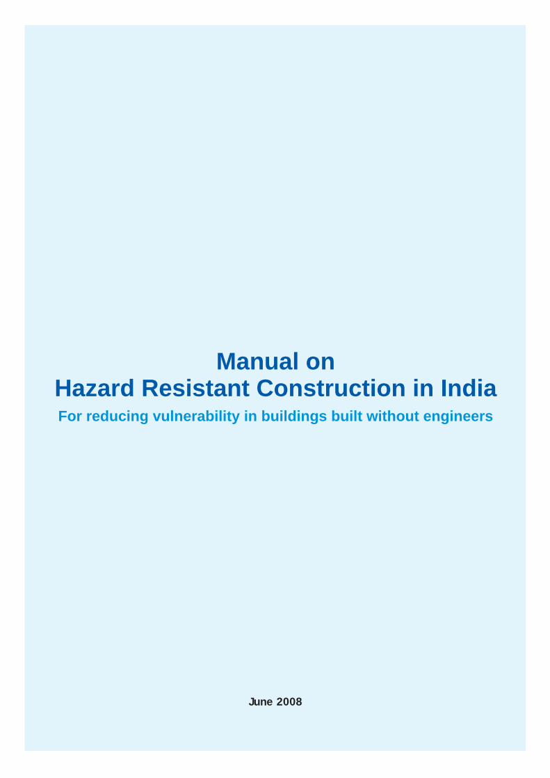
Manual on Hazard Resistant Construction in IndiaFor reducing vulnerability in buildings built without engineers
June 2008

Prepared by Rajendra Desai and Rupal DesaiWith the support from NCPDP team under GOI-UNDP DRM Programme
The use and sharing of information contained in this document is encouraged, with due acknowledgment of the source.
The views expressed in this document are those of the authors. They do not necessarily represent those of the Ministry of Home Affairs (MHA) or United Nations Development Programme (UNDP) or any other part of the United Nations system.
The designations employed and the presentation of material throughout this publication do not imply the expression of any opinion whatsoever on the part of UNDP concerning the legal or development status of any country, city or area or of its authorities or concerning the delimitation of its frontiers or boundaries.
All Photographs © NCPDP, 2007, UNDP license for the use of the photographs allows reproduction of the images as part of this publication only, and not independently.
National Centre For People's - Action In Disaster Preparedness. (NCPDP)103,"Antariksh Building" Panjarapole Cross Roads, Vikram Sarabhai Marg, Ahmedabad - 380 015.Gujarat - (India) Tel : 079 - 26300970, Fax : 079 - 2630 8843.Email : [email protected], Website : ncpdpindia.org
Preface
III
Natural phenomena like earthquake and cyclones become disasters because of lack of awareness on how to construct affordable disaster resistant houses by using viable technologies. It has been observed that this ignorance results in the violation of the basic rules of good construction and hazard resistant technology leading to deaths, injury and unwarranted hardship to the people along with huge losses in terms of houses and infrastructure. In addition to the direct losses caused by the disaster it has been observed that the people suffer self-inflicted losses out of ignorance and under the influence of the unscientific myths that prevail after the disasters. For example the Latur Earthquake made people think that there was no future in their houses that were built out of stone, wood and mud, or those with foundation built on soil instead of on rock, or those that were made with load-bearing system. This led them to get their houses dismantled and sell the salvaged material at a throw away price. As a result tens of thousands of families lost perfectly good undamaged houses.
This manual focuses on construction of hazard resistant masonry buildings as well as restoration and retrofitting of the existing masonry buildings .It has been observed that even RCC construction is also often done in a non-engineered manner. Hence, some basic but critical information is provided on RCC construction also. Since the manual is meant to guide contractors, masons and house-owners, a maximum possible use of visuals including photographs of actual construction has been made with text included where required. The manual is based on various codes and guidelines of Bureau of Indian Standards and is linked to the Vulnerability Atlas made by Ministry of Housing and Urban Poverty Alleviation, GoI. In addition the practical experience of the authors for the past one and a half decades in retrofitting of hundreds of vernacular structures as well as in construction of new houses applying hazard resistant technology with local materials in widely differing regions of the country has provided a sound footing in the preparation of this manual.
It should be noted that the list of rules and measures given in this manual is not exhaustive. But the most critical rules are covered. The measures given here cover the most common types of buildings in the country. The understanding of the underlying principles should help the reader to evolve measures for other situations.
Since there are great variations in the construction practice of masonry structures in different parts of the country, some of the important regional variations are also included in the manual to enable the house owner and the masons to relate to various measures in reference to the locally used construction methods.
The information provided in this manual is essentially for the higher risk areas including Seismic Zones III, IV and V, Wind Speed Zones III and IV with wind speeds ranging from 47 to 55m./second, and the areas affected by the floods. But the people in the other zones also could refer to it for guidance.
The manual has evolved to be comprehensive on account of the reasons indicated above. It is expected that masons will be initiated in the use of this manual as a part of a training program so that they get the maximum benefit out of the Manual. Once the training is completed this Manual can be used as a reference book to be used as often as required. This manual is equally useful to the site supervisors, engineers, and by those wanting to get their house built by a mason. We earnestly hope that they too would make use of this manual.
Finally, it is intended that this manual will help in reducing the undue losses and hardships to the people when struck by an earthquake, cyclone or a flood, and that it becomes an important tool in making India less vulnerable to disasters.
IV
The primary objective of GOI-UNDP Disaster Risk Management programme (DRM) being implemented across 169 multi hazard prone districts in 17 states is sustainable reduction in disaster risk through capacity building of different stakeholders. In order to meet this objective several training programmes have been carried out for the engineers, architects and masons/artisans in different cities covered under Urban Earthquake Vulnerability Reduction Project (UEVRP) as well as in the districts targeted under Disaster Risk Management Programme on hazard resistant construction.
Studies carried out by the authors of this manual in the aftermath of the various disasters in the past fifteen years have brought out one major fact that the death and destruction that occurred during these disasters are primarily due to collapse of buildings and houses which were not constructed on the principles of hazard resistant construction. Under the impact of the natural forces such generated by earthquakes, floods, cyclones the vulnerable buildings collapse and cause death of innocent people and many a times it has been observed that such collapses take place due to ignorance about the right methods of construction.
In rural areas of India as well as in the semi urban pockets a major part of the housing construction is undertaken with the help of local masons without any intervention of the engineers. These masons are usually trained in an informal way and begin their career as assistants to senior masons. The capacity of such masons depends on the skills of senior masons. It has been observed that most of them do not possess the required capacity to build hazard resistant buildings, which is evident from the devastation in Latur, Uttarkashi, Chamoli and Bhuj earthquake and Orissa super cyclone. Therefore, the priority of the masons' training programmes conducted under the Disaster Risk Management Programme has been on skill upgradation of practicing masons through appropriate hands-on training.
This manual can be used as a ready reference by the trained masons and will also be equally helpful for the site supervisors, engineers and homeowners who want their houses to be built by masons. The manual will be translated in regional languages to reach out to the target groups at the local level.
The masons will be introduced and exposed to this manual by their trainer. The information provided in this manual cover three major hazards ie Earthquakes, floods and cyclones. The manual mentions all the necessary construction codes to be followed in order to ensure structural safety in seismic zone III, IV and V , in wind speed zones III and IV with a wind speed of 47 to 55 km /hour and the areas prone to floods. The manual throws light on the critical aspects to be followed in new construction that are commonly violated. Appropriate visuals have been used to make this manual user-friendly. In the section on restoration of damage and retrofitting of existing buildings every important aspect has been covered step by step using visuals. For greater emphasis the right and wrong are indicated by bright red symbols.
It is expected that this joint effort of Ministry Of Home Affairs, GOI and UNDP in bringing out this manual for on hazard resistant construction practices in India will contribute towards ensuring structural safety and development of safer built environment in India.
FOREWORD
Pieter BultDeputy Country Director DirectorUnited Nations Development Programme Ministry of Home Affairs, Government of IndiaNew Delhi New Delhi
Rajiv Kumar

ACKNOWLEDGEMENTS
First and foremost we the authors appreciate this initiative taken up under GOI-UNDP Disaster Risk Management Programme. This manual was accomplished under the guidance and constant support from senior officials of Ministry Of Home Affairs, Mr. Sushil Kumar, Assistant Country Director, UNDP and Mr. G. Padmanabhan, Emergency Analyst, UNDP. As always the technical guidance and constructive comments from Shri Anand Swaroop Arya, National Seismic Advisor, Ministry Of Home Affairs, has been crucial in ensuring completeness in the manual and in bringing credibility and value to the manual. A word of thanks is also due to Ms. Ranjini Mukherjee, Mr. Sushil Chaudhary and Ms. Shafali Rajora for providing all necessary support required to complete this manual
Relevant Building Codes & Guidelines of Bureau of Indian Standards as well as the Government Technical Guidelines for disaster resistant building construction prepared in the aftermath of various disasters form the basis for this manual. On the other hand two decades of our work in the field of building technologies through field demonstrations and onsite training of masons and engineers, coupled with community awareness programs form the backbone of this manual. In addition it is backed by a large number of manuals and public awareness materials that we have produced in five different languages of India for as many regions.
In much of our disaster mitigation related field work we have had good fortune of associating with a few pioneers in this field including Retd. Prof.A.S.Arya of IIT Roorkee and Retd. Prof. K.S. Jagadish of IISC Bangalore. Their input always brought in sound engineering to our work dictated by the practical considerations of field.
Through out these years of working with the building artisans, the artisans themselves have been the principal source of learning, especially from the immense pool of vernacular knowledge . It has been only these artisans that have kept our hopes of vulnerability reduction through bringing improvements in the non-engineered building scenario alive. The culmination of these feelings was experienced in our work with 28 master masons in the Uri Region of Kashmir in the summer of year 2006.
Among those that we have been closely working with we must acknowledge the valuable support that we got from Ajay Madhwani, Harshad Talpada and Ajay Kankrecha of the NCPDP team in putting together this document, Shri B.J. Karani in doing meticulous proof reading as well as review as a non-technical person, and finally Shri Dinkar Shah in providing guidance in the chapter on RCC.
All our work with building technology had been accompanied by extensive photographic documentation with a sole objective of sharing the experience with others. As a result all the photographs used in this manual have been selected out of our own collection.
Rupal Desai and Rajendra DesaiAhmedabad, GUJ.
V

ABBREVIATIONS
VI
AbbreviationsWORDS
National Center of Peoples'- Action in Disaster Preparedness
AC Asbestos cementApprox. Approximately
Burnt brick in cement mortarBBCMBBMM Burnt brick in mud mortarBMTPC Building Material Technology Promotion CouncilCem. CementCGI Corrugated galvanized ironCM Cement mortarcm CentimeterCum. Cubic meterCWM Chicken wire meshDia. Diameter
DistanceDist.Eqk. Earthquake
HorizontalHorz.Kilogramkg.
km. KilometerLt Litrem MeterMax. MaximumMin. Minimummm Milli meterMS Mild steelNCPDPNDMD National Disaster Management DivisionNo. / no. NumberRC Reinforced concreteRCC Reinforced cement concreteRRM Random rubble masonryRmt. Running meterSmt. Square meterSq.m. Square meter
UCRCUCRM
Un-coursed rubble masonry in cement mortarUn-coursed rubble masonry in mud mortar
UNDP United Nations Development ProgramVerticalVert.
WWM Welded wire mesh
ga. Gauge

TABLE OF CONTENTS
Chapter Contents Page Number
1 Introduction to Disaster Prone Areas......... 1
2 Building Systems................................... 5
3 Damage Types & Reasons ....... 9
4 Vulnerability Identification..................... 17
5 Basic Rules of Disaster Resistant Design.............. 19
6 Basic Rules of Good Quality Construction................... 29
7 Disaster Resisting Features ........ 40
8 Disaster Resisting Features - Regional Variations..................... 62
9 Material Quantities for Disaster Resisting Features......................... 67
10 Don'ts - New Construction............................... 71
11 Restoration Procedures................................. 75
12 Retrofitting Measures..................................... 82
13 Material Quantities for Retrofitting Measures........... 96
14 Don'ts - Restoration & Retrofitting................... 100
15 Tools and Equipment for Retrofitting.................... 102
16 Basic Rules of Good Quality Non-Engineered RC Construction .............. 104
Appendix................................. 109
VII

1t
cio
tIn
ro
du
tn
o
is
en
As
Ds
at
r P
ro
ere
a
The map of India printed here shows the types of ea r thquake tha t can possibly occur and the risks involved. The person can locate his area on the map and become aware of the possible risk of future earthquake.
There are four different zones: Numbered II, III, IV & V.Zone II has the lowest risk and Zone V has the highest risk.
Earthquake Risk
In India different types of natural disasters like earthquake, cyclone and flood bring death and destruction in many places every year. To reduce the impact of disasters, people must know about the risk of different disasters and destruction they can bring, and building artisans should learn the techniques.
This manual is aimed at helping the building artisans improve their skills and learn about the disaster-resistant building technologies that they can use in their region. It can also be used by site supervisors, engineers and house owners to learn the practical aspects of such technologies.
This manual covers the most commonly used masonry walls including brick, concrete blocks and stone, and the most commonly used roofs including pitched roofs with roofing materials consisting of clay tiles and AC & CGI sheeting, and flat roof consisting of mud timber roof and RC slab.
1

1Manual on Hazard Resistant Construction in India
Zone III :Kachcha Buildings: About 75% will have large cracks and 5% will have collapsed portions.Semi Pucca Buildings : About 75% will have large cracks.Pucca Buildings: About 75% will have small cracks, and 5% will have large cracks.
Zone IV :Kachcha Buildings: About 75% will have collapsed portions.Semi Pucca Buildings: About 75% will have large cracks, about 5% will have collapsed portions.Pucca Buildings: About 75% will have small cracks, and about 5% will have large cracks.
Large cracks
Collapsed portions
Building CategoryKachcha Structures: Having walls made of mud, unburned bricks or soft stone.Semi Pucca Structures: Having walls made of bricks, good quality stone, concrete blocks.Pucca Structures: Walls made with cement mortar, timber and reinforced concrete.
*
Expected Damage In Future Earthquake to Different Category Buildings*
Moderate and fine cracks
Zone II:Kachcha Buildings: About 50% will have fine cracks and about 5% moderate cracks.Semi Pucca Buildings: About 25% will have fine cracks.Pucca Buildings: No damage.
Zone V :Kachcha Buildings: About 75% will collapse fully.Semi Pucca Buildings: About 50% will have collapsed portions and about 5% may collapse fully. Pucca Buildings: About 50% will have large cracks, and about 5% will have collapsed portions.
2
Total collapse

2 1There are four zones based on expected maximum wind speeds in the area. Zone I has the lowest risk and Zone IV has the highest.
Low Damage Risk Wind Speed up to 33m/sWell-built Semi-Pucca Buildings: Very little damage.Loose corrugated galvanized iron (CGI) & fibre cement sheets and clay tiles fly off.
Moderate Damage Risk Wind Speed 39 to 44m/s Kachcha and Semi-Pucca Buildings: Moderate damage.Loose roofing clay tiles fly off; some roof sheets fixed to purlins also fly off.
High Damage Risk Wind Speed 47m/sKachcha and Semi Pucca Buildings: Heavy damageBoundary Walls: OverturnIndustrial Buildings: Walls fail, whole roofs may fly off.
Very High Damage Risk Wind Speed 50 to 55 m/s Similar to Zone III but the damage is more widespread as in a severe cyclone.
Cyclone Risk
Blown off tiles due to high winds Wall collapse due to tidal surge
Expected Damage In Future Cyclone
The map on this page shows areas known to experience high winds and cyclones. The person constructing a building in such area must take in to consideration the damage that can occur.
3
Zone I:
Zone II:
Zone III:
Zone IV:
Manual on Hazard Resistant Construction in India

This map shows the areas that are known to experience major floods. Those constructing buildings in such an area must take into account the danger of flooding from rivers. In addition there could be a problem of local flooding due to heavy rains. The map also shows the tidal surge that can be expected.
Flooding and fast moving water can cause structural damage due to water inundation and settlement of foundation due to scouring.
Flood Risk
Water Innundation Damage due to foundation settelement
Expected Damage In Future Flood
1
4
Manual on Hazard Resistant Construction in India

No
n-E
ng
ine
ere
d B
uil
dn
g S
ys
te
ms
i
This is used for majority of houses and infrastructure buildings in villages, towns and cities. The walls carry all the loads and also resist forces of earthquake, cyc- lone and flood. It uses materials that are most easily available locally.
This is used in towns and cities usually for multi-storey buildings. The RC frame carries all the loads and also resists forces of earth-quake, cyclone and flood. The cladding walls provide the security to the occupants from rain, cold, heat, and thieves.
In past few decades with increasing prosperity, improved availability of longer lasting materials, and timber becoming very expensive, the materials used have changed significantly and continue to change. As a result many building systems have become economically unviable.
1.Load Bearing Masonry System
2 Majority of buildings in rural and semi-urban parts of the country are built by people with the help of local building artisan s with no help from engineers. These may be Kutcha or Pucca. These buildings generally have no more than two storeys. Two main pucca building systems are shown below.
‘
Most Common Non-Engineered Building Systems in India
2.Reinforced Concrete Frame
Recent Transformation in Building Systems
This system is used based on engineering design but, some buildings are constructed without the help of an engineer.
5
This manual focuses only on those non-engineered building systems that are most popular and are most likely to remain in use across the
disaster prone areas of the country.
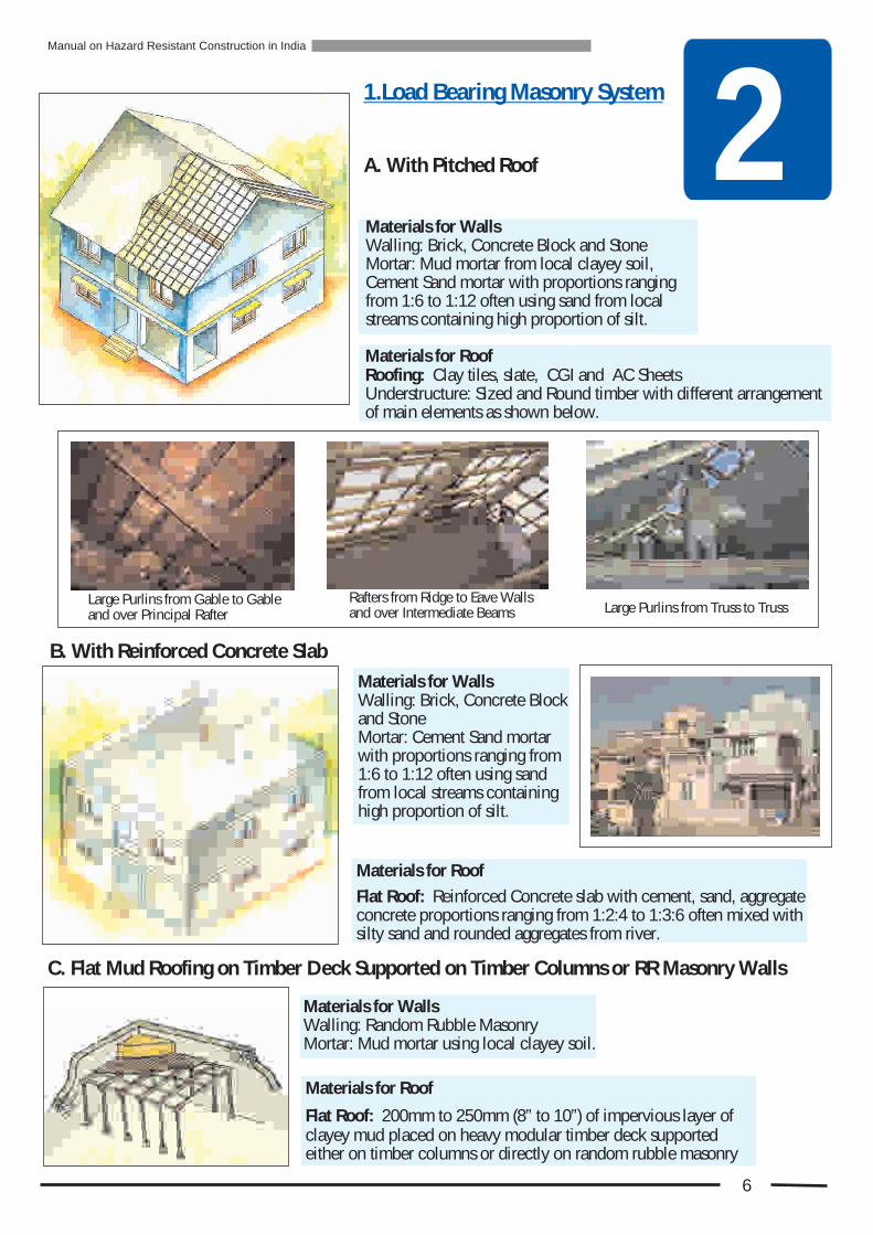
Materials for Roof
Flat Roof: Reinforced Concrete slab with cement, sand, aggregate concrete proportions ranging from 1:2:4 to 1:3:6 often mixed with silty sand and rounded aggregates from river.
2
6
1.Load Bearing Masonry System
Materials for Walls Walling: Brick, Concrete Block and Stone Mortar: Mud mortar from local clayey soil, Cement Sand mortar with proportions ranging from 1:6 to 1:12 often using sand from local streams containing high proportion of silt.
Materials for Roofing: Clay tiles, slate, CGI and AC SheetsUnderstructure: Sized and Round timber with different arrangement of main elements as shown below.
Roof
C. Flat Mud Roofing on Timber Deck Supported on Timber Columns or RR Masonry Walls
Materials for WallsWalling: Brick, Concrete Block and StoneMortar: Cement Sand mortar with proportions ranging from 1:6 to 1:12 often using sand from local streams containing high proportion of silt.
A. With Pitched Roof
Large Purlins from Gable to Gable and over Principal Rafter
Rafters from Ridge to Eave Walls and over Intermediate Beams Large Purlins from Truss to Truss
Materials for WallsWalling: Random Rubble MasonryMortar: Mud mortar using local clayey soil.
Materials for Roof
Flat Roof: 200mm to 250mm (8” to 10”) of impervious layer of clayey mud placed on heavy modular timber deck supported either on timber columns or directly on random rubble masonry
B. With Reinforced Concrete Slab
Manual on Hazard Resistant Construction in India
2
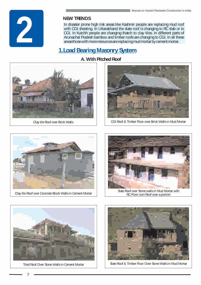
CGI Roof & over Brick Walls in Mud MortarTimber Floor
Slate Roof over Stone walls in Mud Mortar withRC Floor cum Roof over a portion
Tiled Roof Over Stone Walls in Cement Mortar Slate Roof & Timber Floor Over Stone Walls in Mud Mortar
In disaster prone high risk areas like Kashmir people are replacing mud roof with CGI sheeting. In Uttarakhand the slate roof is changing to RC slab or to CGI. In Kutchh people are changing thatch to clay tiles. In different parts of Arunachal Pradesh bamboo and timber roofs are changing to CGI. In all these areas those with more resources are replacing mud mortar by cement mortar.
NEW TRENDS
Clay tile Roof over Brick Walls
Clay tile Roof over Concrete Block Walls in Cement Mortar
1.Load Bearing Masonry System
A. With Pitched Roof
7
Manual on Hazard Resistant Construction in India
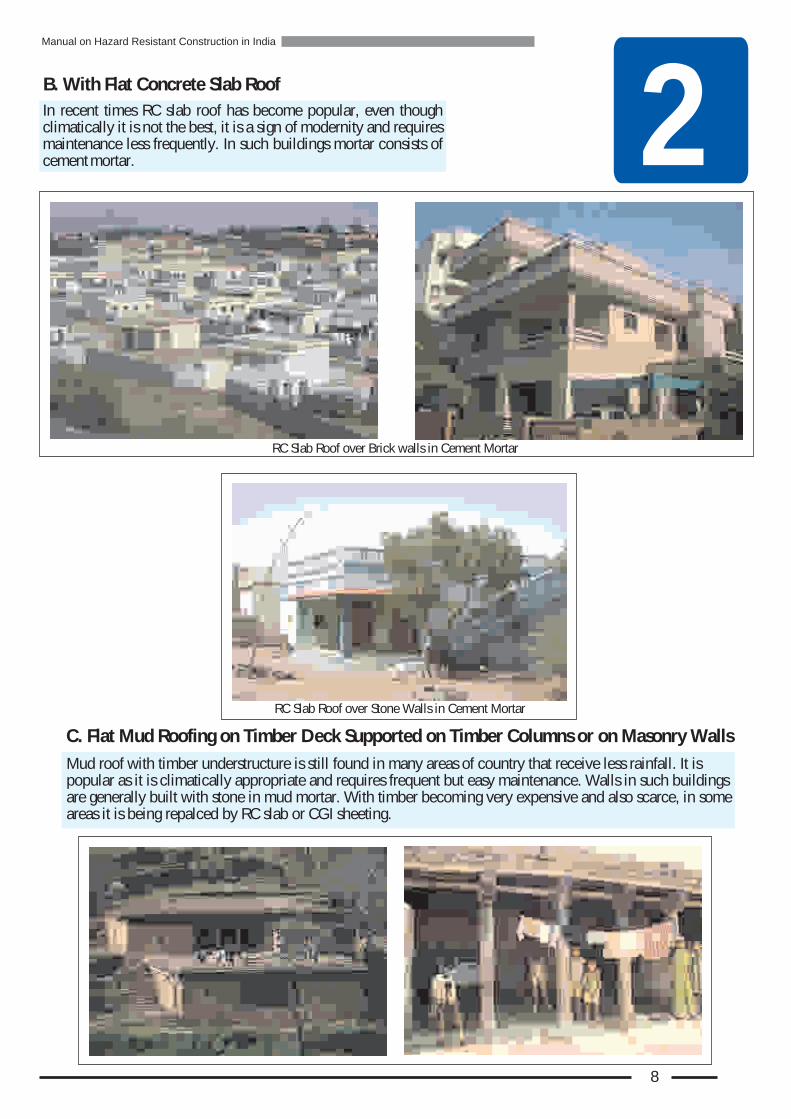
2B. With Flat Concrete Slab Roof
In recent times RC slab roof has become popular, even though climatically it is not the best, it is a sign of modernity and requires maintenance less frequently. In such buildings mortar consists of cement mortar.
C. Flat Mud Roofing on Timber Deck Supported on Timber Columns or on Masonry Walls
Mud roof with timber understructure is still found in many areas of country that receive less rainfall. It is popular as it is climatically appropriate and requires frequent but easy maintenance. Walls in such buildings are generally built with stone in mud mortar. With timber becoming very expensive and also scarce, in some areas it is being repalced by RC slab or CGI sheeting.
RC Slab Roof over Brick in Cement Mortarwalls
RC Slab Roof over Stone Walls in Cement Mortar
8
Manual on Hazard Resistant Construction in India

Da
ge
: T
yp
es
&
ea
so
ns
ma
R
3Earthquake, Cyclone and Flood, each one exerts a variety of forces, directly and indirectly, on buildings. The important factors that cause damage to buildings are
! Types of weaknesses in the building.
! Direction, speed and duration with which the hazard strikes a building.
! Earthquake : Magnitude (Richter Scale), the depth of epicenter and buildings' distance from it.
! Cyclone : Wind speed, and accompanying rain.
! Flood : Depth and duration of flood, and speed of water.
Vertical Crack away from cornerCause: Wall is not able to withstand tension caused by its bending.
Diagonal Crack Cause: The wall is not able to withstand tension resulting from elongation in dia-gonal direction.
Diagonal Crack at the corner of the window and the doorCause: Wall with openings is weak aga-inst tension in diagonal direction.
Horizontal Crack at the base of Gable WallCause: Gable wall is unable to resist tension at its base caused by its back and forth shaking (bending).
Crack under a beamCause: Wall is unable to resist splitting tension due to concentrated load from the beam during earthquake.
Damage Due to Natural Hazards
Earthquake makes the building and its parts bend, elongate, compress and twist. Various walls move in different directions. This causes tension in the walls and at the junction of various parts of the building. If the strength is not adequate then the damage occurs. Since mortar makes a significant contribution to the strength of masonry, the weaker the mortar, more sever is the damage.
Earthquake Damage : Types & Causes
Vertical Crack at the CornerCause: Corner is weak and not able to take tension between two walls.
9

3Wall bulgedCause: In thick stone walls its outer and inner wythes (faces) are not interlocked adequately, and with shak-ing their separation begins, resulting in to bulging.
Slab sliding from its positionCause: The weak joint between slab and wall is not able to withstand the horizontal force exerted by the slab on the wall.
Wall with one face fallen and other intact (Delamination)Cause: In thick stone walls its outer and inner wythes (faces) are not interlocked adequately, and with shak-ing one face separates and collapses.
Cracked Masonry ColumnCause: The masonry column is not able to withstand tens-ion resulting from its bending caused by the horizontal pu-sh from the roof supported on it.
Wall with small portion at top having collapsedCause: Weak Wall without adequate roof anchoring is not able to withstand tension caused by back and forth bending.
Wall going out of plumbWith both corners cracked wall loses its supports at ends. Any further shaking makes it tilt and go out of plumb.
Earthquake damage: Types & Causes
Collapse of a part of the slabCause: Portion of support wall collapses, depriving support to a part of slab, resulting in the collapse of that part.
10
Manual on Hazard Resistant Construction in India

3
Portion of support wall collapses resulting in the collapse of roof understructure.
Sudden shock causes breakage of rotten beam.
Parapet collapse
Badly cracked wall Diagonal cracking at opening
Corner cracks and roof damage
11
Photographs of Earthquake Damage to Walls
Collapse of Roof Understructure Collapse of Roof Understructure
Manual on Hazard Resistant Construction in India
Masonry column cracking
3
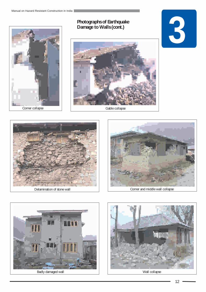
Corner and middle wall collapseDelamination of stone wall
Gable collapseCorner collapse
Wall collapseBadly damaged wall
12
Photographs of Earthquake Damage to Walls (cont.)
Manual on Hazard Resistant Construction in India
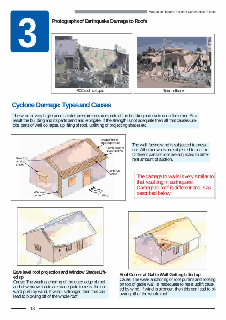
The wind at very high speed creates pressure on some parts of the building and suction on the other. As a result the building and its parts bend and elongate. If the strength is not adequate then all this causes Cra-cks, parts of wall collapse, uplifting of roof, uplifting of projecting shades etc.
The wall facing wind is subjected to press-ure. All other walls are subjected to suction. Different parts of roof are subjected to diffe-rent amount of suction.
Roof Corner at Gable Wall Getting Lifted upCause: The weak anchoring of roof purlins and roofing on top of gable wall is inadequate to resist uplift caus-ed by wind. If wind is stronger, then this can lead to bl-owing off of the whole roof.
Cyclone Damage: Types and Causes
The damage to walls is very similar to that resulting in earthquake. Damage to roof is different and is as described below:
Projecting window shades.
Windwardcorner Wind
Cantileverportion
Corner areas ofsevere suction
Areas of higher suction/pressure.
Eave level roof projection and Window Shades Lift-ed upCause: The weak anchoring of the outer edge of roof and of window shade are inadequate to resist the up-ward push by wind. If wind is stronger, then this can lead to blowing off of the whole roof.
3RCC roof collapse Total collapse
13
Photographs of Earthquake Damage to Roofs
Manual on Hazard Resistant Construction in India

3
Collapse of wall and damage to roof
Damage to rear wall by suction
Damage by Cyclonic Surge Wall & Roof damage by Cyclone
Roof Tiles blown off
14
Photographs of Cyclone Damage
Manual on Hazard Resistant Construction in India
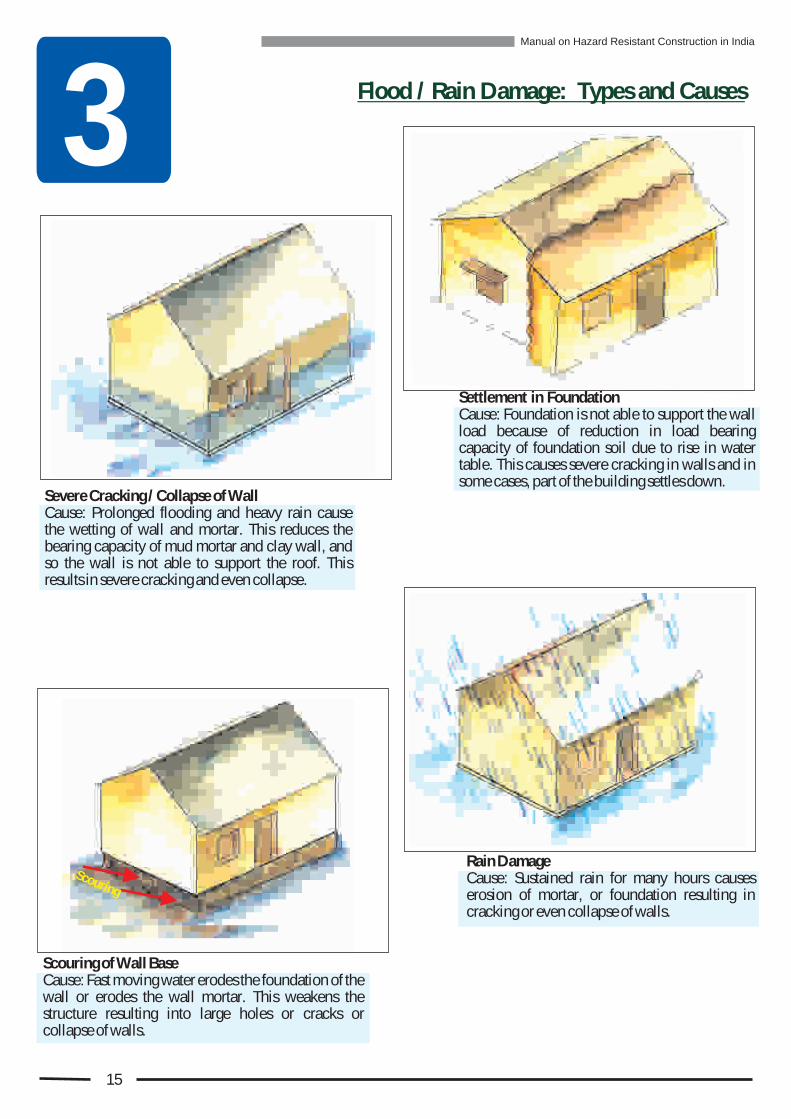
3 Flood / Rain Damage: Types and Causes
Severe Cracking / Collapse of WallCause: Prolonged flooding and heavy rain cause the wetting of wall and mortar. This reduces the bearing capacity of mud mortar and clay wall, and so the wall is not able to support the roof. This results in severe cracking and even collapse.
Settlement in FoundationCause: Foundation is not able to support the wall load because of reduction in load bearing capacity of foundation soil due to rise in water table. This causes severe cracking in walls and in some cases, part of the building settles down.
Scouring of Wall BaseCause: Fast moving water erodes the foundation of the wall or erodes the wall mortar. This weakens the structure resulting into large holes or cracks or collapse of walls.
Rain DamageCause: Sustained rain for many hours causes erosion of mortar, or foundation resulting in cracking or even collapse of walls.
Sco ring u
15
Manual on Hazard Resistant Construction in India

3
Prolonged flooding Collapse of wall due to mud mortar weakening
Foundation Settlement due to rising ground water level Scouring of mud mortar from open joints by fast moving water
Scouring of wall base & cracked wall Erosion and scouring of mud wall by heavy rain
16
Photographs of Flood & Rain Damage
Manual on Hazard Resistant Construction in India

Vu
lne
ail
ity
Ie
ntif
ica
tio
rb
d
n 4
In India masonry structures are built with similar construction practices using stone, bricks, concrete blocks, unbaked bricks or mud blocks for walls, with a variety of mor-tars including mud and cement mortars with widely differing proportions of different in-gredients. The weaknesses in these walls are similar, but vary in degree of damagability because of varying strengths of the mortar as well as the quality of construction. The remedial measures to tackle these weaknesses are also similar except for the mud (clay) walls.
The bamboo and timber walled buildings are light weight and flexible.
In case of roofs the materials like clay tiles, CGI or AC sheets, slate, mud, thatch etc are used. Their support systems differ a great deal, thus requiring different remedial mea-sures.
Ekra style timber-bamboo wallsMud wall and thatch roof house
This manual covers load bearing masonry walls of stone, bricks, and concrete blocks, with mud and cement mortar, and pitched roofs with clay tiles, CGI/AC sheeting, and slate, and flat roof consisting of mud and RC slab.
r aTimbe w lls
The weaknesses or vulnerabilities in a building against forces of earth-quake, cyclone and flood must be identified in order to decide the rem-edial measures necessary to make the building safer.
For mud walls there are no simple measures to make them disaster resistant
For thatch roof there are no simple remedial measures to make them cyclone resistant
Bamboo and timber walled buildings are earthquake resistant
.
.
Hence, in this manual the walls made of earth, bamboo or timber, and roof made of thatch are not included.
17
Vulnerability of Non-Engineered Buildings against Earthquake, Cyclone & Flood Hazards

4
rth kEa qua e Wind Fl & aood R in
Based on the studies of damages to non-engineered structures due to various hazards the commonly observed vulnerability is shown in the diagram below. It is important to identify and apply the remedial measures for these.
k al to- alWea w l - w lo ec .c nn tion
se c of du til ty Ab n e c iin ver cal i ecti n.ti dr o
s c of stor y to-Ab en e e - of con c oro ne ti n.
A nce f sto ey- - bse o r tosto ey co e t or nn c i n.
s n o nMa o ry with po r te sile g n te .stren th agai st aring
or tr ngt f ga e gainst Po s e h o bl ac a for s aki .ba k nd th h ng
D a ona tea i g at i g l r nop ni g corn rs.e n e
In- l ne d orma o of floorpa ef ti n rectan le h nging to ar llelogr m.g c a p a a
cAbsen e f c nnection o orbetween oo an wall .fl d s
o oSide ay push fr m ro f wlr fters to al .a w
I -plane deformation in ner of causi g sid way o n
a e .push o the g bl walln
a i & W ak nchor n of sheet nge g i t o mit les o ro f fra n .i g
W ak nchor n of r ofi g to e a i g o ng ble wal and oof aming.a l r fr
Wea a c oring doo / k n h of rwind w fr me to w l .o a al
Ea i y Br k bl s l ea a eLa ge Gl s Pa lr a s ne. i th evel er n g maPl n l low tha hi h flood rk.
Plinth s nry i mud ma o nm rtar with op n j i ts at o e on thcan e sily b er ded.a e o
s nc of mos tur Ab e e i eb rr er that ermit a i pwe in of mu mort .tt g d ar
c of pa ster nAbsen e l i g o pointing rmit we nr pe tti g of mu mor r. d ta
Ab e es nc of tie at a je ve proe ction.
c of con oAbsen e necti nb e ro ab aletw en of sl & w l.
High masonry parapet with no ductility and no anchoring to floor.
E W F
FF
Poor co nection be weenn t oof aming a d wal .r fr n l
CE
In a building with RC Slab roof the vulnerabilities be-low the roof level are same as those in a pitched roof building. But above that level they are different.
Vulnerability of Non-Engineered Buildings against Earthquake, Cyclone & Flood Hazards
Load Bearing Masonry Building with flat RC Roof
WE
WE
WE
WE
WE
WE
WE
WE
WE
WE
WE
WE
WE
WE
WE
WE
W
W
FF
FF
FF
WE
Load Bearing Masonry Building with Pitched Roof
VULNERABILITY AT A GLANCE
WE
Masonry with poor horizontal bending strength.
18
Manual on Hazard Resistant Construction in India

Ba
sic
le
o
Ru
s
f
Dis
as
te
r R
eis
ta
t e
si
ns
nD
g 5
First Step in Disaster Safety
1. Examples for Better Understanding of Disaster Resistant Construction Principles
Bus moves on bumpy roads but does not fall apart because all its sides, top and bottom are connected together solidly.
A cardboard box open at the top with some weight in it, gets distorted if you lift it. But if its flaps at the top are closed , its shape does not change when lifted.
A house is like a bus or a cardboard box. If all its walls, roof and foundation are tied together well it will not fall apart or deform if shaken by an earthquake or a cyclone.
Adhering to the basic rules that provide guidance on the planning and designing of a disaster resistant building is the first step in safety against disaster. This is irrespective of what materials are used in construction.
19
51. Examples for Better Understanding of Disaster Resistant Construction Principles (Cont.)
20
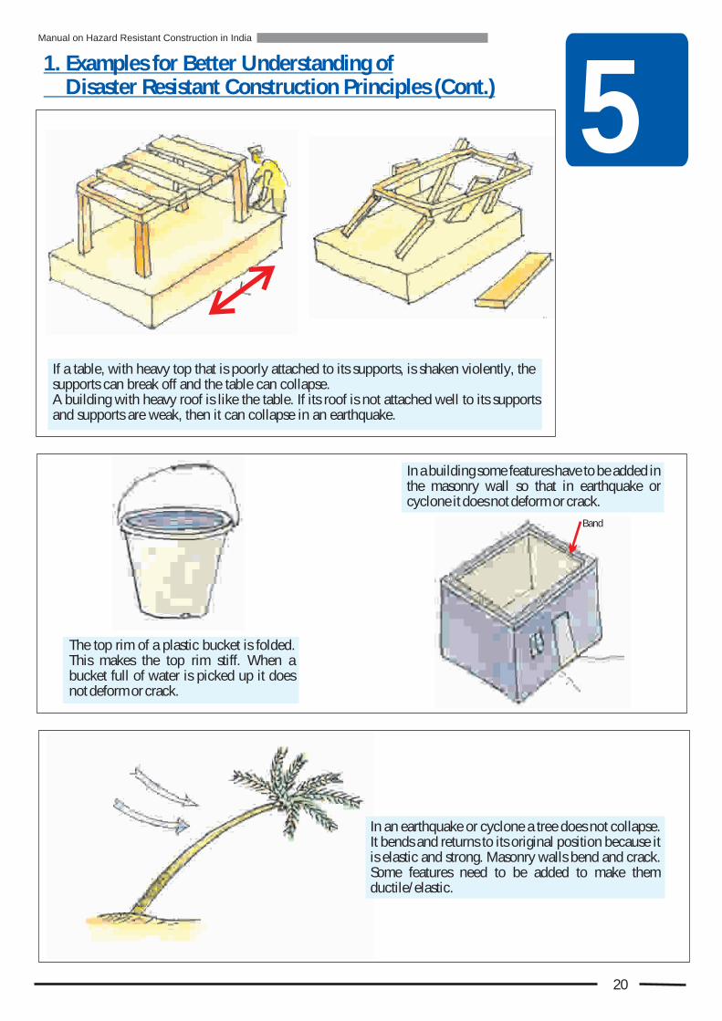
If a table, with heavy top that is poorly attached to its supports, is shaken violently, the supports can break off and the table can collapse.A building with heavy roof is like the table. If its roof is not attached well to its supports and supports are weak, then it can collapse in an earthquake.
The top rim of a plastic bucket is folded. This makes the top rim stiff. When a bucket full of water is picked up it does not deform or crack.
Band
In a building some features have to be added in the masonry wall so that in earthquake or cyclone it does not deform or crack.
In an earthquake or cyclone a tree does not collapse. It bends and returns to its original position because it is elastic and strong. Masonry walls bend and crack. Some features need to be added to make them ductile/ elastic.
Manual on Hazard Resistant Construction in India

W
5Rules described here apply to different hazards. But all the rules help in making the building stronger and lasting longer. With each rule a special symbol is assigned for its applicability to a particular hazard.
2. Locating the Building
If higher ground is not available then construct on artificially raised ground or on stilts.
E Earthquake W F Flood & Rain
W FW F
The shelters should not be laid out in straight rows to prevent the tunnel effect during cyclones.
Adopt a non-regular layout.
F
E
1m 1m
Retaining Wall
Cut slope
Top of slope
Wind
Avoid all low lying areas for construction as it can be inundated with water in case of heavy rain.
Select site that is sheltered From cyclonic winds.
W
C
Construct building at least 1m away from top of slope and 1m away from the cut. Also construct retaining wall to support very steep cut slope.
21
Manual on Hazard Resistant Construction in India

5Building with symmetrical plan is safer than the one with asymmetrical plan.
3. Building Plan & Form
E WIt is best to divide the building into a number of symmetrical units.
E W
House with verandah in one corner can get damaged more easily than a house with verandah in the centre or with verandah symmetrically located in corners on both sides.
E W
Avoid making buildings with plans having 'C', 'H', 'T', or 'L' shapes in disaster prone areas.
E W
E
L greater than 7
m
22
Square plan of a building is safer than the long rectangular building plan with walls longer than 7m (23’). C
Manual on Hazard Resistant Construction in India

5
Building with four-sided sloping roof is stronger than the one with two- sided sloping roof.
Roof overhang must be no more than 500mm (20”) in rainy areas. In dry areas like Kutchh it can be as little as 150mm (6”)
500 maxWW
House should be ideally square or round.The pyramid shaped roof is ideally suited.
E W
For pitched roof the roof slope should be
o 0 between 22 to 30for greater cyclone safety.
Gable walls in two-sided sloping roof collapse easily.
o 022 to 30
L gre ter than 3 B
ax
B
3. Building Plan & Form (Cont.)
Gable wall
No Gable wall
23
W
E W
Very long building can get damaged or even collapse easily than a shorter building. Avoid constructing a house with length more than 3 times its width “B”. Otherwise divide the building in two separate units.
Manual on Hazard Resistant Construction in India
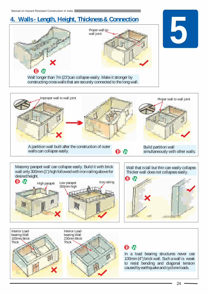
5Wall longer than 7m (23’)can collapse easily. Make it stronger by constructing cross walls that are securely connected to the long wall.
E W
Proper wall-to- wall joint
E W
Masonry parapet wall can collapse easily. Build it with brick wall only 300mm (1’) high followed with iron railing above for desired height.
Wall that is tall but thin can easily collapse. Thicker wall does not collapses easily.
E W
E W
In a load bearing structures never use 100mm (4”) brick wall. Such a wall is weak to resist bending and diagonal tension caused by earthquake and cyclone loads.
E W
A partition wall built after the construction of outer walls can collapse easily.
Build partition wall simultaneously with other walls.
Iron railingHigh parapet Low parapet 300mm high
Proper wall to wall jointImproper wall to wall joint
Interior Load-bearing Wall100mm Brick Thick
Interior Load-bearing Wall230mm Brick Thick
4. Walls - Length, Height, Thickness & Connection
24
Manual on Hazard Resistant Construction in India

5High load walls on sloping roof collapse easily like parapet wall. Construct load walls no higher than 230mm (9”) and reinforce it with reinforcing rod inside for greater strength.
E W
Low load wall only 230mm high with 8mm Tor reinforcing bar
Load-wall taller than 230mm without any reinforcement
If gable wall is taller than 1m then it is safer to build it with lighter material like CGI sheets or timber planks.
E WHeight of the gable walls shall not be more than 1000 mm (3’-4”)above eave level.
To prevent cracks at the corners, strengthen them by constructing buttresses in the corners.
In long walls buttresses must be provided. For their spacing and maximum wall length see Chapter 7
Gable Height Max. 1m
E W
E WE W
5. Walls - Openings
E FW
Timber or CGI gable walls
Too many openings in one wall
Only one opening in one wall
ll L
egt
Wa
nh
4. Walls - Length, Height, Thickness & Connection (Cont.)
25
In smaller rooms provide no more than one opening in each wall.
Walls with too many doors and windows close to each other could collapse easily. Opening should be restricted to small sizes and few in numbers.
Manual on Hazard Resistant Construction in India
5
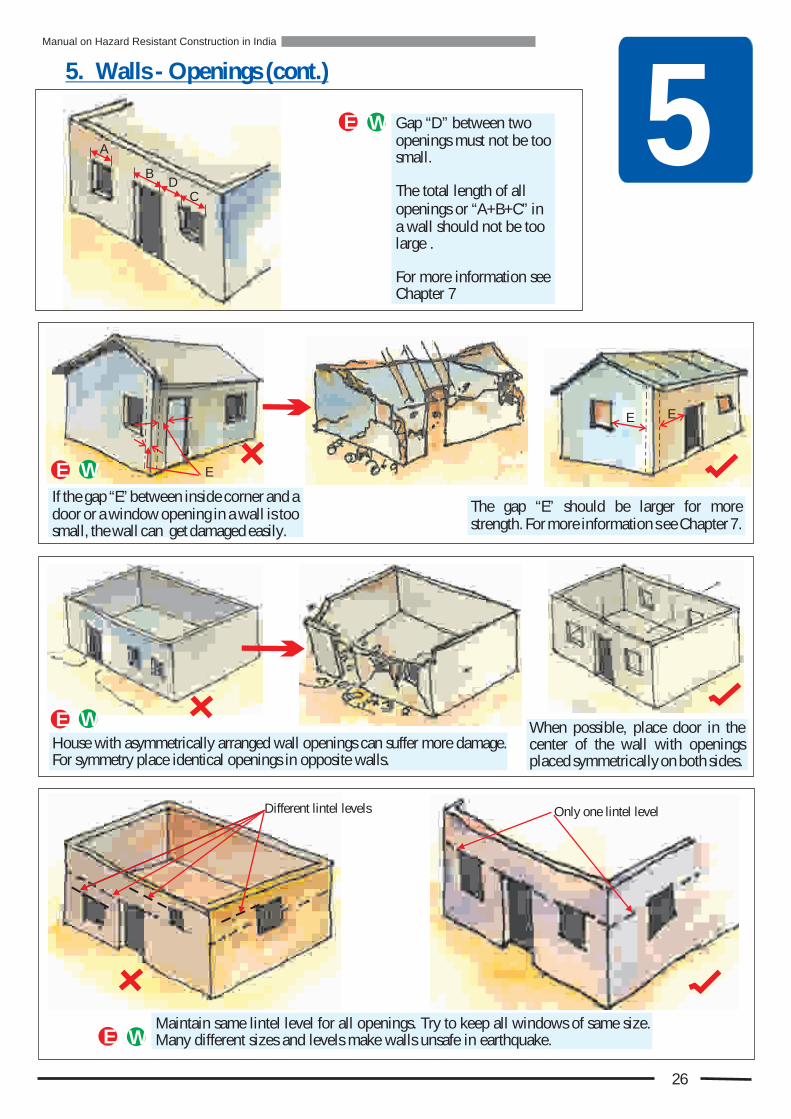
The gap “E” should be larger for more strength. For more information s ee Chapter 7.
If the gap “E” between inside corner and a door or a window opening in a wall is too small, the wall can get damaged easily.
E W
Maintain same lintel level for all openings. Try to keep all windows of same size. Many different sizes and levels make walls unsafe in earthquake.E W
Only one lintel levelDifferent lintel levels
E W When possible, place door in the center of the wall with openings placed symmetrically on both sides.
House with asymmetrically arranged wall openings can suffer more damage. For symmetry place identical openings in opposite walls.
D
5. Walls - Openings (cont.)
26
E
B
C
A
E E
Gap “D” between two openings must not be too small.
The total length of all openings or “A+B+C” in a wall should not be too large .
For more information see Chapter 7
E W
Manual on Hazard Resistant Construction in India
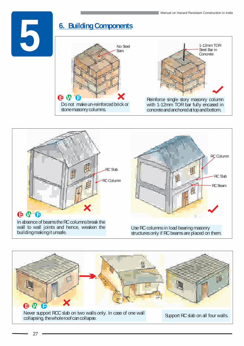
56. Building Components
E FWDo not make un-reinforced brick or stone masonry columns.
No Steel Bars
ENever support RCC slab on two walls only. In case of one wall collapsing, the whole roof can collapse.
E FW
Support RC slab on all four walls.
RC Slab
RC Beam
RC SlabRC Column
RC Column
1-12mm TOR Steel Bar in Concrete
27
Reinforce single story masonry column with 1-12mm TOR bar fully encased in concrete and anchored at top and bottom.
In absence of beams the RC columns break the wall to wall joints and hence, weaken the building making it unsafe.
E FW
Use RC columns in load bearing masonry structures only if RC beams are placed on them.
Manual on Hazard Resistant Construction in India
5
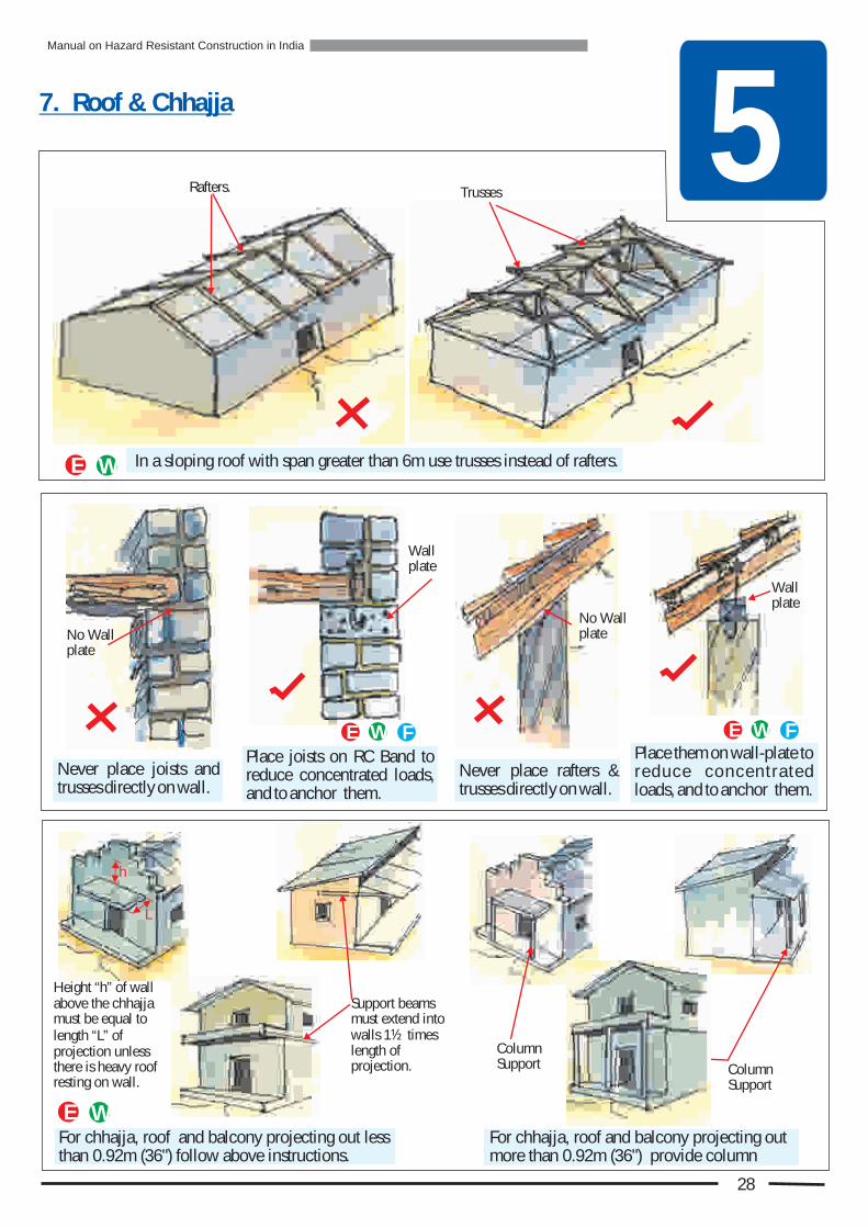
For chhajja, roof and balcony projecting out less than 0.92m (36") follow above instructions.
E W
Rafters. Trusses
Column Support
Height “h” of wall above the chhajja must be equal to length “L” of projection unless there is heavy roof resting on wall.
Wall plate
Wall plate
No Wall plateNo Wall
plate
7. Roof & Chhajja
28
Support beams must extend into walls 1½ times length of projection.
For chhajja, roof and balcony more than 0.92m (36") provide column
projecting out
Column Support
L
h
In a sloping roof with span greater than 6m use trusses instead of rafters.E W
Place them on wall-plate to reduce concent ra ted loads, and to anchor them.
Never place rafters & trusses directly on wall.
E FW
Never place joists and trusses directly on wall.
Place joists on RC Band to reduce concentrated loads, and to anchor them.
E FW
Manual on Hazard Resistant Construction in India
Bs
ic R
les o
o
da
uf
Go
ua
lity C
on
tru
ctio
nQ
s 6
Adhering to the principles of good construction is the
. Due to mistakes by mason the quality suffers. As a result efforts and money spent on special disaster safety measures may still not bring safety.
second step in safety against disaster
To ensure safety follow all the rules and do not make mistakes
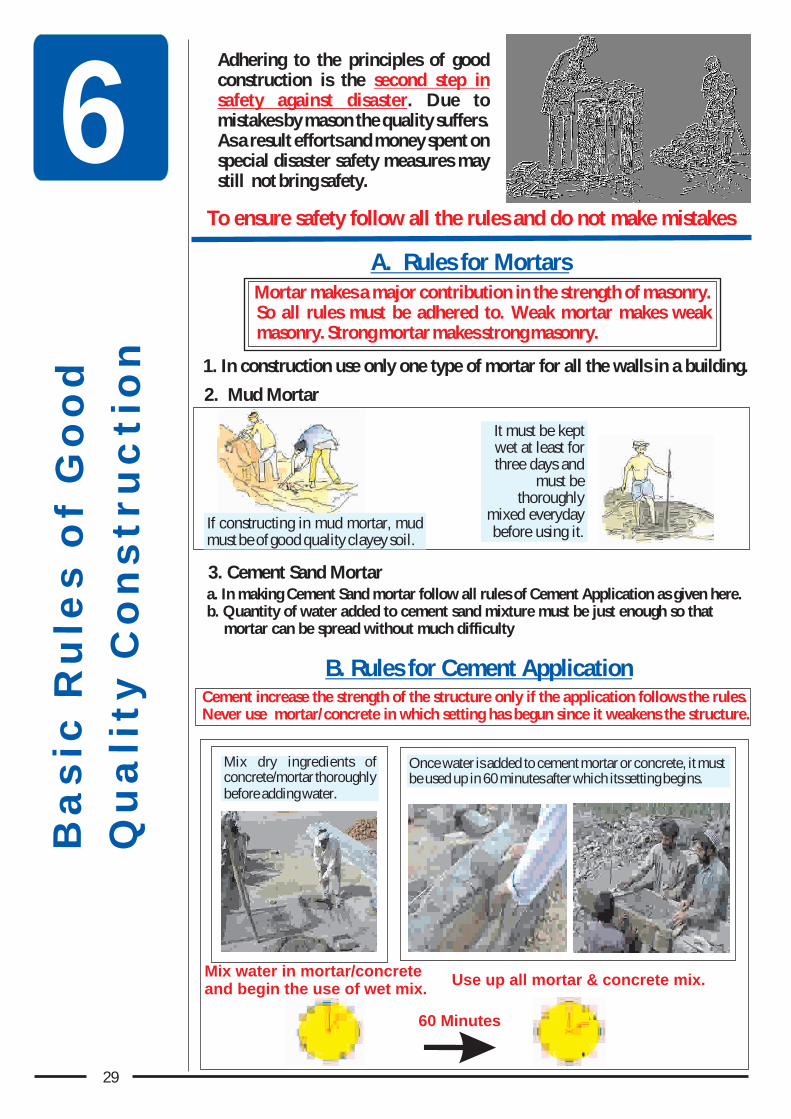
A. Rules for MortarsMortar makes a major contribution in the strength of masonry. So all rules must be adhered to. Weak mortar makes weak masonry. Strong mortar makes strong masonry.
a. In making Cement Sand mortar follow all rules of Cement Application as given here.b. Quantity of water added to cement sand mixture must be just enough so that
mortar can be spread without much difficulty
1. In construction use only one type of mortar for all the walls in a building.
3. Cement Sand Mortar
If constructing in mud mortar, mud must be of good quality clayey soil.
It must be kept wet at least for three days and
must be thoroughly
mixed everyday before using it.
B. Rules for Cement Application
Mix dry ingredients of concrete/mortar thoroughly before adding water.
Mix water in mortar/concrete and begin the use of wet mix.
Use up all mortar & concrete mix.
60 Minutes
Once water is added to cement mortar or concrete, it must be used up in 60 minutes after which its setting begins.
Cement increase the strength of the structure only if the application follows the rules.Never use mortar/concrete in which setting has begun since it weakens the structure.
29
2. Mud Mortar

6B. Rules for Cement Application (cont.)
4. Silt content in sand should not be more than 10%
5. Remove silt by pouring sand against wind or by washing
2. Use fine sand only for plastering.1. Sand must be angular and not rounded.
2. Curing of Cement Mortar/ Concrete
C. Rules for Sand Application
30
3. Sieve sand to remove small pebbles.
To check silt content in sand put some sand in a transparent jar, add water, shake it well and put it down so that all of it settles down and water becomes clear. The thickness of very fine powder at the top divided by the total thickness of soil in the jar gives the % of silt in the soil.
43 Grade cement is preferred over 53 Grade cement for the construction of houses and small infrastructure buildings.
1. Cement Selection
D. Rules for Aggregate Application
2. Do not use round aggregate from river in concrete. It has poor bond with cement and so it produces weaker concrete.
1. Do not use aggregates larger than 30mm (1¼”).
Sand
Silt
Manual on Hazard Resistant Construction in India
Cement mortar becomes stronger by keeping it wet
continuously without letting it dry. Keep it wet for a minimum 10 days and to get maximum strength keep it wet for 28 days.
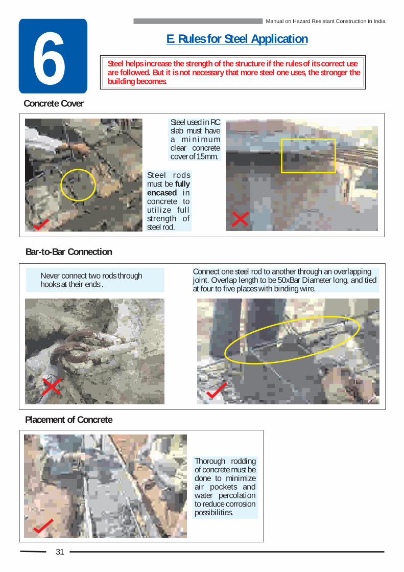
6E. Rules for Steel Application
Steel helps increase the strength of the structure if the rules of its correct use are followed. But it is not necessary that more steel one uses, the stronger the building becomes.
Concrete Cover
Steel used in RC slab must have a m i n i m u m clear concrete cover of 15mm.
S t ee l r od s must be fully encased in concrete to uti l ize full strength of steel rod.
Bar-to-Bar Connection
Connect one steel rod to another through an overlapping joint. Overlap length to be 50xBar Diameter long, and tied at four to five places with binding wire.
Never connect two rods through hooks at their ends .
Placement of Concrete
Thorough rodding of concrete must be done to minimize air pockets and water percolation to reduce corrosion possibilities.
31
Manual on Hazard Resistant Construction in India

Backfill in the foundation trench must be properly compacted.
Remove all loose materials including water from foundation trench and compact the bottom before constructing foundation.
Soft Soil - Minimum 90 cm (3’)
Rock- 7.5 to 10 cm (3” to 4”)
Hard Soil- Minimum 60 cm (2’)
F. How deep should be the Foundation ?
Follow all rules of masonry construction given in this chapter in the construction of foundation.
Make “Strip” foundation under the wall that is wider than wall.
Wall Masonry
Foundation Masonry
Plinth Level
Foundation Masonry WidthHard SoilWidth = 2 x Wall ThicknessSoft SoilWidth = 3 x Wall Thickness
Wdthi
6
G. Foundation Masonry
32
Decide the foundation depth depending upon how strong the ground is.
Decide how strong the ground is using the following simple test on dry ground.
! Remove top 150mm (6”) of soil and all the fill so that virgin soil is exposed
! Take a crow bar 1540mm (60½ long and weighing 4.5 kg.
! Hold it vertical with its sharp point towards ground at 600mm (24") above the ground.
! Drop it, ensuring that it falls vertically.
! Based on the penetration of the bottom end determine if soil is hard or soft.
)
Manual on Hazard Resistant Construction in India

H. General Rules of Masonry - For Brick, Concrete Blocks & Stone
1. Wall-to-Wall Connection
1. Do not build only corners of a house at first or just one wall at a time.
4. Do not use toothings to connect w a l l s - p a r t i t i o n w a l l s a n d o t h e r i n t e r i o r a n d e x t e r i o r w a l l s .
2. Build all the walls at the same time along with the corners to ensure strong connection between them.
4
2
5. All interior and exterior walls must be built at the same time. Alternatively, if exterior wall is being built first then at each interior wall bring out the masonry from exterior wall in stepped-like manner to which the interior walls are to be connected.
5
While building an extension to existing building connecting with toothings on existing building makes a very weak connection.
Connect the extension to the existing building using 10mm dia. TOR rods at 900mm (36") vertical spacing placed in 50mm (2”) groove long in the walls of the existing building .
600mm (24")
6 7
Existing Building Extension
3. If this is not followed then leave the end of the wall in steplike manner.
1 3
6
33
Connected with toothing only
8600mm embbeddment
10mm dia. TOR bar
Extension
900mm spacing
Manual on Hazard Resistant Construction in India

2. Wetting Concrete Blocks, Soft Stone and Bricks
3. Using Tube Level, Plumb Bob & String for Placing Next Course
Use tube level in every second or third course to maintain uniform thickness of mortar.
Use plumb bob while beginning each new course at the corner to ensure that the wall is in plumb.
Use stretched string in every course to ensure that wall remains in plumb.
T h o r o u g h l y s o a k B r i c k , Concrete Block or soft Stone in wa te r when using them with cement mortar to ensure strong masonry.
Wet brick
Break all the vertical joints.
All vertical joints must be 10mm to 15mm wide, and
must be filled properly with
mortar.
4. Vertical Joints
6
34
H. General Rules of Masonry - For Brick, Concrete Blocks & Stone (cont.)
Manual on Hazard Resistant Construction in India

6. Mixing of Different Materials in Masonry Work
Do no t u se d i f f e r e n t materials next to each other at the same level.
Material in the masonry can be changed at different horizontal levels, if necessary.
5. Placing Mortar
Mortar left on top of masonry, if hard, has to be chipped off before placing mortar for the next course, to ensure good bond. This is a waste of mortar and labour.
Place mortar on top of a masonry course only when ready to put the next course.
Sill Level
Plinth Level
Such a change can be made at: ! Plinth Level
6
35
H. General Rules of Masonry - For Brick, Concrete Blocks & Stone (cont.)
Manual on Hazard Resistant Construction in India
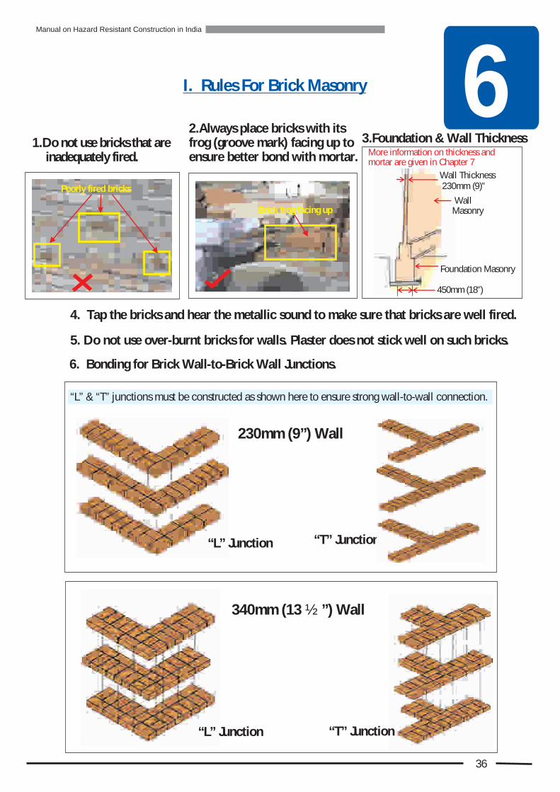
6. Bonding for Brick Wall-to-Brick Wall Junctions.
“L” & “T” junctions must be constructed as shown here to ensure strong wall-to-wall connection.
2.Always place bricks with its frog (groove mark) facing up to ensure better bond with mortar.
I. Rules For Brick Masonry
4. Tap the bricks and hear the metallic sound to make sure that bricks are well fired.
5. Do not use over-burnt bricks for walls. Plaster does not stick well on such bricks.
340mm (13 ½ ”) Wall
“T” Junction
Brick frog facing up
1.Do not use bricks that are inadequately fired.
Poorly fired bricks
6
36
3.Foundation & Wall Thickness
“L” Junction “T” Junction
230mm (9”) Wall
“L” Junction
Manual on Hazard Resistant Construction in India
Wall Thickness 230mm (9)”
Wall Masonry
450mm (18”)
Foundation Masonry
More information on thickness and mortar are given in Chapter 7

6J. Rules For Concrete Block Masonry
2. Dimensions & Types of Concrete Block
3. The top and bottom surfaces must be rough for good bond.
5.If blocks are freshly made then they must be cured.
Smooth surface Rough surface
Strong edges
4. The blocks should be strong with strong edges.
1. Foundation & Wall Thickness
“T” Junction
6. Bonding for Block Wall-to-Block Wall Junctions.
“L” &” T” junctions must be constructed as shown here to ensure strong wall to wall connection
200m
m
(8")
50mm 16")(
300m (12")m
Hollow BlockSolid Block
Dimensions same as solid block
Wall Thickness35mm Min.
“L” Junction
Solid Concrete Block should be no bigger than300x200x150mm(12”x8”x6”) so that it can easily be carried by one person.
37
200mm (8'')
Wall Masonry
Foundation Masonry
Manual on Hazard Resistant Construction in India
More information on thickness and mortar are given in Chapter 7
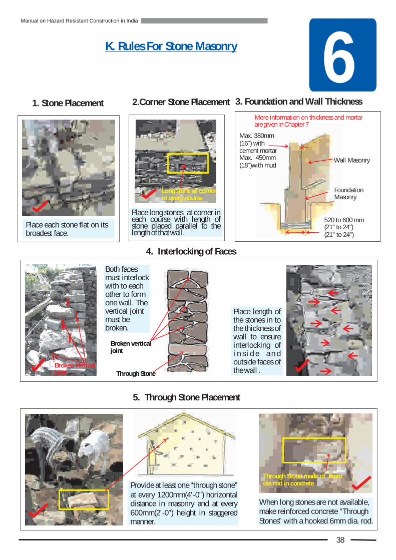
Provide at least one “through stone” at every 1200mm(4'-0”) horizontal distance in masonry and at every 600mm(2'-0”) height in staggered manner.
When long stones are not available, make reinforced concrete “Through Stones” with a hooked 6mm dia. rod.
4. Interlocking of Faces
5. Through Stone Placement
2.Corner Stone Placement
Place each stone flat on its broadest face.
Place long stones at corner in each course with length of stone placed parallel to the length of that wall.
Through Stone made of 8mm dia rod in concrete
Long stone at corner in every course
Both faces must interlock with to each other to form one wall. The vertical joint must be broken.
Place length of the stones in to the thickness of wall to ensure interlocking of i n s i d e a n d outside faces of the wall .
Broken vertical joint
1. Stone Placement
K. Rules For Stone Masonry
3. Foundation and Wall Thickness
6
38
More information on thickness and mortar are given in Chapter 7
Max. 380mm (16”) with cement mortarMax. 450mm (18”)with mud
Wall Masonry
Foundation Masonry
520 to 600 mm (21" to 24")(21” to 24”)
Broken vertical joint
Through Stone
Manual on Hazard Resistant Construction in India

8. Use of Round Stone
Fill all voids using small chips of stone with minimum possible use of mortar.
Stone must be broken to make it angular so that it has no rounded faces.
In the portion of foundation below ground do not use round stones, and do not just dump stones.
In the portion of foundation below ground stones must be placed as per rules of masonry.
K. Rules for Stone Masonry (cont.)
9. Stone Masonry Below Ground
Never use round stones for masonry. Round stones are very slippery. So a wall made with them is unstable.
7. Voids in Stone Masonry
6. Courses in Stone Masonry
Random Rubble Masonry must be done in courses.
Max. Course height = 600mm (24”)
Rounded face
Stones just dumped in foundation trench
Stones properly placed in foundation trench
Round Stones
6
39
Manual on Hazard Resistant Construction in India

as
i
Dis
te
r R
es
ist
ng
Fe
atu
re
s
Nn
in
ew
Co
stru
ctio
n
7Scientific, Cost efficient, Easy to execute, Locally appropriate, Dependent on easily available materials and Culturally suitable
In addition to following the one must follow the
given here, and include in the new construction as shown here to eliminate all the weaknesses present in the building as shown in Chapter 4
Rules of Disaster Resistant Design Rules of Good Quality Construction, Special Rules for Masonry Walls Disaster Resisting Features
and
How to build a disaster resistant house that will not collapse in a disaster ?
1.Special Rules for Masonry Walls for For Seismic Zones III, IV & V
Earthquake Resistant Construction
To reduce the death and destruction arising out of natural hazards, a building must be so built that it resists the forces of the hazards expected in future. It is important to ensure this approach with every new building.
For every new building to be disaster resistant the construction technology has to be:
Stone Masonry Structure - Latur
Stone Masonry Structure - Uttarakhand
40
A. Stone Masonry Walls
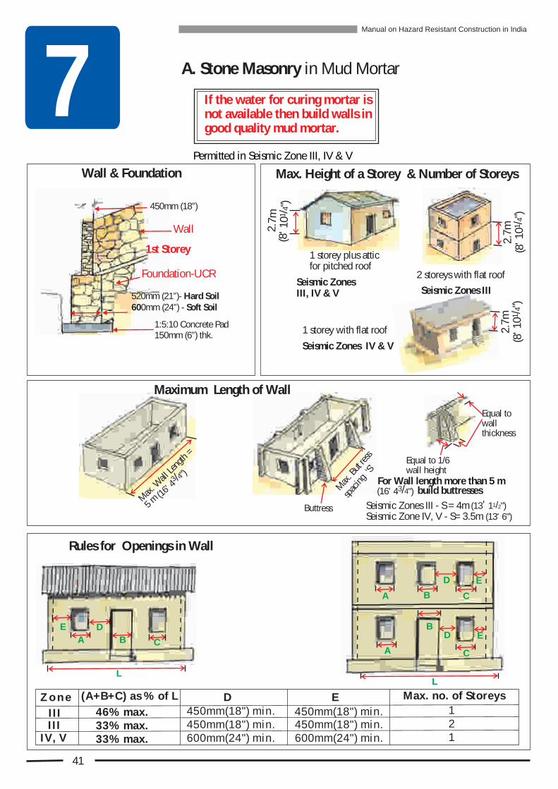
7Max. Height of a Storey & Number of Storeys
1 storey with flat roof
1 storey plus attic for pitched roof
Buttress
Mx
But
s
a.
t re
s
aci
‘’
spng
S
Equal to 1/6 wall height
Equal to wall thickness
A C
DE
B
Rules for Openings in Wall
L
Seismic Zones III, IV & V
41
A. Stone Masonry in Mud Mortar
2 storeys with flat roof
Seismic Zones IV & V
Seismic Zones III
If the water for curing mortar is not available then build walls in good quality mud mortar.
450mm (18”)
Foundation-UCR
Wall
1st Storey
520mm (21”)- Hard Soil 600mm (24”) - Soft Soil
1:5:10 Concrete Pad 150mm (6”) thk.
Permitted in Seismic Zone III, IV & V
Wall & Foundation
A
A
B
B
L
D
D
C
C
E
E
Z o n e (A+B+C) as % of L
450mm(18") min. 450mm(18") min.
Max. no. of StoreysD E
IIIIII
IV, V
46% max.33% max.33% max.
450mm(18") min. 450mm(18") min.600mm(24") min. 600mm(24") min.
1
12
Maximum Length of Wall
72.
m 1/ 4
10(8
' ")
7m2.
1/ 4
10
"(8
')
2.7m
1 /4
(8' 1
0")
3 /4
(16' 4
")
a. W
ll n
h =
Mx
aLe
gt
5 m
Seismic Zones III - S = 4m Seismic Zone IV, V - S= 3.5m (13' 6")
1/2' (13 1 ")
3/4(1 ' 4 )6 "For Wall length more than 5 m
build buttresses
Manual on Hazard Resistant Construction in India
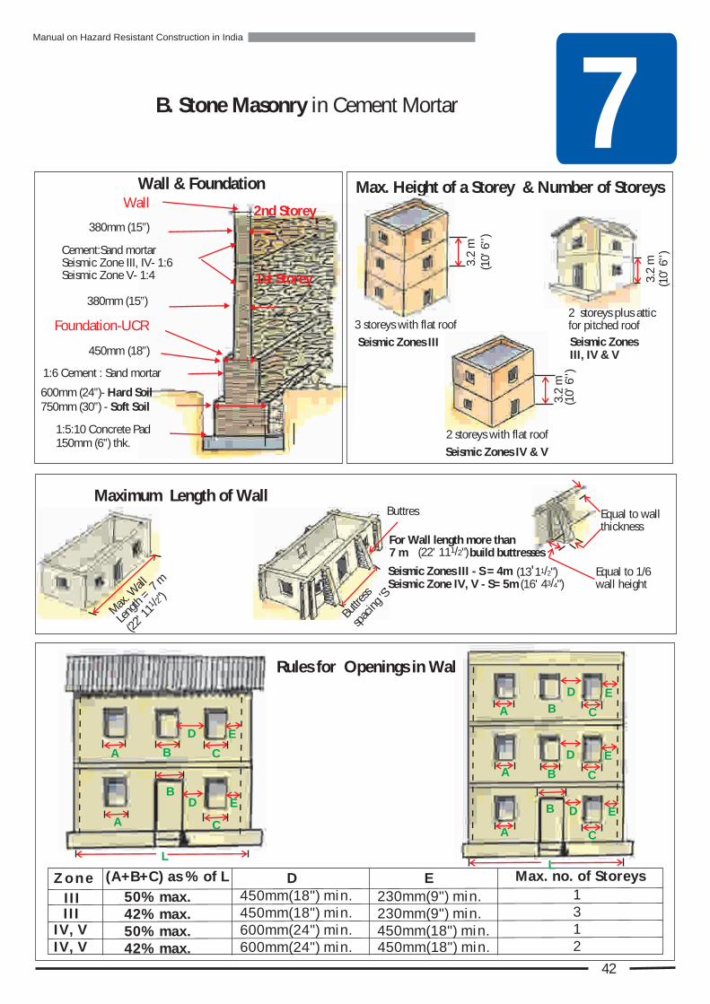
380mm (15”)
450mm (18”)
1:6 Cement : Sand mortar
380mm (15”)
Wall
Foundation-UCR
1st Storey
2nd Storey
Cement:Sand mortarSeismic Zone III, IV- 1:6Seismic Zone V- 1:4
1:5:10 Concrete Pad 150mm (6”) thk.
600mm (24”)- Hard Soil750mm (30”) - Soft Soil
Wall & Foundation
7B. Stone Masonry in Cement Mortar
Maximum Length of Wall
C
D
EB
E
B C
D
A
A
L
42
Z o n e (A+B+C) as % of L
450mm(18") min.
450mm(18") min.
Max. no. of StoreysD E
IIIIII
IV, V
50% max.42% max.50% max.
450mm(18") min.
450mm(18") min.600mm(24") min.
1
13
IV, V 42% max. 600mm(24") min.
230mm(9") min.230mm(9") min.
2
Rules for Openings in Wall
D
BA
E
C
D
BA
E
C
C
EB D
A
L
3.2
m
Max. Height of a Storey & Number of Storeys
2 storeys plus attic for pitched roof
32
m.
Seismic Zones III, IV & V
32
m.
3 storeys with flat roof
Seismic Zones III
2 storeys with flat roof
Seismic Zones IV & V
(10'
6'')
(10'
6'')
(10'
6'')
s
Buttre
s s
‘’
paci
ngS
tBu tres
Equal to 1/6 wall height
Equal to wall thickness
Seismic Zones III - S = 4mSeismic Zone IV, V - S= 5m
1/2'(13 1 ")3/(16' 4 4")
For Wall length more than 1 2/(22' 11 ")7 m build buttresses
Mx
l
a. W
al
g
m
Len
th= 7
1 2/
22'
")
(11
Manual on Hazard Resistant Construction in India

7 If the water for curing mortar is not available then build walls in good quality mud mortar.
C. Brick Masonry in Mud Mortar
1 storey with flat roof1 storey plus attic for pitched roof
Seismic Zone IV & V
Equal to 1/6 wall height
Equal to wall thickness
A C
DE
B
Rules for Openings in Wall
Max. Height of a Storey & Number of Storeys
2.7
m
Permitted in Seismic Zone III, IV & V
2 storeys with flat roof
Seismic Zone III
Seismic Zone III, IV & V
A
A
B
B
D
D
C
C
E
E
43
340mm (13½”)
Wall 1st Storey
1:5:10 Concrete Pad 150mm (6”) thk.
450mm (18”)- Hard Soil690mm (27”) - Soft Soil
Foundation - Brick/ UCR in mud mortar
Wall & Foundation
Z o n e (A+B+C) as % of L
450mm(18") min. 450mm(18") min.
Max. no. of StoreysD E
IIIIII
IV, V
46% max.33% max.33% max.
450mm(18") min. 450mm(18") min.600mm(24") min. 600mm(24") min.
1
12
LL
27.
m 1 /4
8
0)
(' 1
"
27.
m 1 /4
8
0)
(' 1
"
Im
a-
n ud m
ortr
ot
an
N m
oreth
5 m
3 /
1
4"
( 6' 4
)
Maximum Length of Wall
Buttress
Btt
ure
sspa
g S
sci
n
Seismic Zones III, IV & V - S = 5m 3/( 6 4"1 ' 4 )
3/(16' 4 4")
For Wall length more than 5 m build buttresses
Manual on Hazard Resistant Construction in India
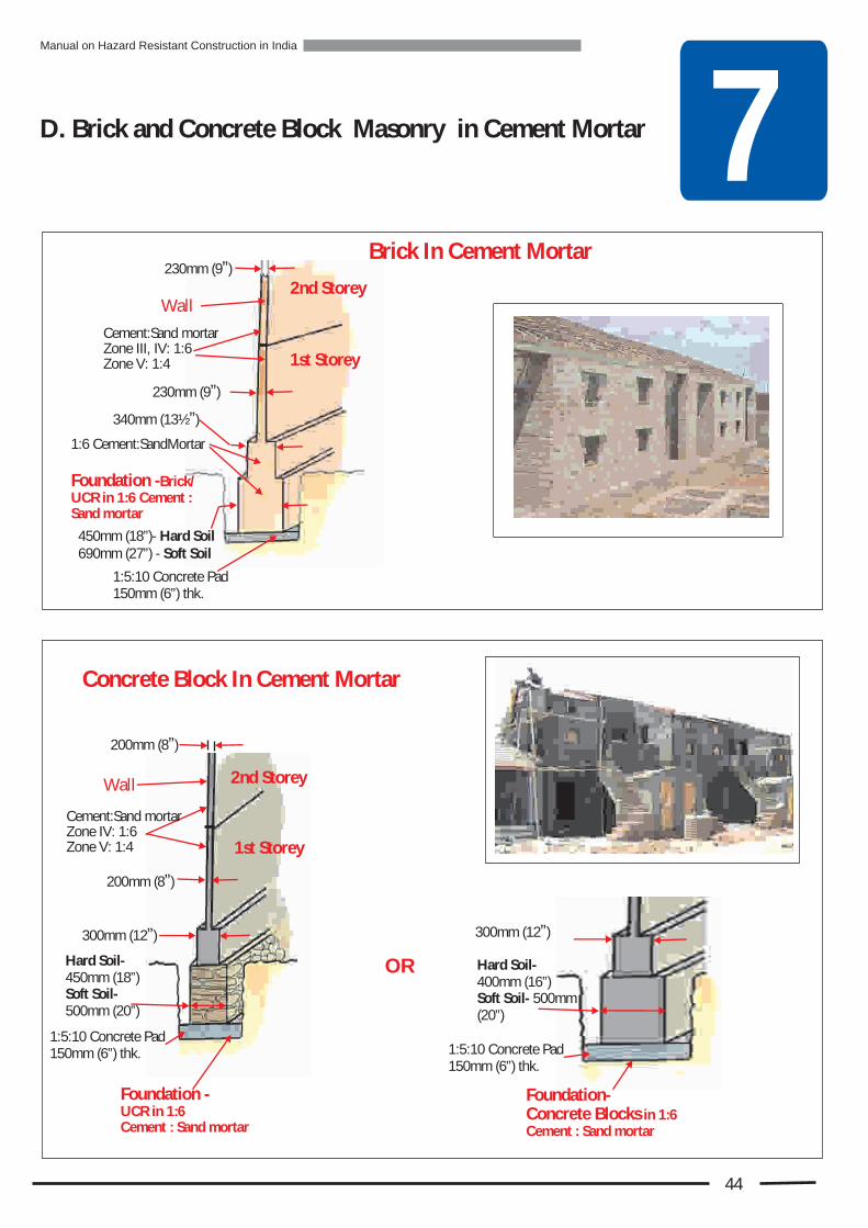
7D. Brick and Concrete Block Masonry in Cement Mortar
Concrete Block In Cement Mortar
300mm (12”)
Foundation- Concrete Blocks in 1:6 Cement : Sand mortar
Hard Soil-400mm (16”)Soft Soil- 500mm (20”)
OR
230mm (9”)
230mm (9”)
1:6 Cement:SandMortar
Brick In Cement Mortar
Wall
Cement:Sand mortarZone III, IV: 1:6Zone V: 1:4
2nd Storey
1st Storey
340mm (13½”)
1:5:10 Concrete Pad 150mm (6”) thk.
450mm (18”)- Hard Soil690mm (27”) - Soft Soil
Foundation -Brick/ UCR in 1:6 Cement : Sand mortar
44
1:5:10 Concrete Pad 150mm (6”) thk.
200mm (8”)
Wall
200mm (8”)
Foundation -UCR in 1:6 Cement : Sand mortar
2nd Storey
1st Storey
Cement:Sand mortarZone IV: 1:6Zone V: 1:4
Hard Soil-450mm (18”)Soft Soil- 500mm (20”)
1:5:10 Concrete Pad 150mm (6”) thk.
300mm (12”)
Manual on Hazard Resistant Construction in India
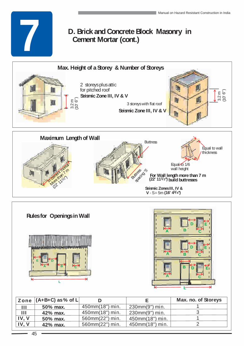
72 storeys plus attic for pitched roof
3.2
m
Maximum Length of Wall
m
In cemen
t orta
r-
eM
or than
7 m
Equal to wall thickness
Buttress
Equal to 1/6 wall height
Seismic Zone III, IV & V
45
Max. Height of a Storey & Number of Storeys
Rules for Openings in Wall
D. Brick and Concrete Block Masonry in Cement Mortar (cont.)
A C
DE
B
L
32
m.
3 storeys with flat roof
Seismic Zone III, IV & V
Z o n e (A+B+C) as % of L
450mm(18") min.
450mm(18") min.
Max. no. of StoreysD E
IIIIII
IV, V
50% max.42% max.50% max.
450mm(18") min.
450mm(18") min.560mm(22") min.
1
13
IV, V 42% max. 560mm(22") min.
230mm(9") min.230mm(9") min.
2
B
sut
tres
sci
n ‘
’
pag
S
D
BA
E
C
D
BA
E
C
C
EB D
A
L
(10'
'') 6
(10'
'') 6
1 2/ 1
(22'1
") 1 2/(22' 1 ")1For Wall length more than 7 m
build buttresses
3 4/ (16' 4 ")Seismic Zones III, IV & V - S = 5m
Manual on Hazard Resistant Construction in India

72. Special Rules for Masonry Walls for
For Wind Speed Zone III & IV(Wind Speeds from 47 to 55m/second)
Cyclone Resistant Construction
3.Special Rules for Masonry Walls for Flood Resistant Construction
Wall Finish: Plaster entire walls with cement plaster on inside and outside. In case of low budget apply cement pointing is a must.
Openings: Make openings small in size and few in numbers. Locate openings closer to middle portion of wall.
Plinth: Building must be constructed with plinth height minimum of 150mm (6”) above previous High Flood Level in cement or mud mortar with cement plaster. For a low budget, Cement pointing is a must.
Make all doors and windows such that they can be tightly shut and sealed during cyclone.
Avoid large central openings or too many openings in a wall.
AH
Identical window openings in opposite walls.
Openings distributed in more walls.
A = At least 1/6 H
46
Manual on Hazard Resistant Construction in India

Earthquake Wind & aFlood R in FWE
Improve roof slab to storey connectivity by providing vertical reinforcement
Build low parapet and anchor it to RC floor
WE
WE
Load Bearing Masonry Building with RC Slab Roof
In a building with RC Slab roof the disaster resisting features below the roof level are same as those in a pitched roof building. But above that level they are different.
7 The Disaster Resisting Features for the most commonly used building systems are shown below at a glance. This is followed by the detailed description.
SPECIAL DISASTER RESISTING FEATURES FOR NEW CONSTRUCTION
Strengthen wall to wall connection with seismic bands at floor and eave level
Induce tensile strength against vertical bending by vertical reinforcement at all room cornersImprove storey to storey
connectivity by providing vertical reinforcement
Anchor top storey to roof with vertical rod
Induce tensile strength in walls against tearing and horizontal bending with horizontal seismic bands
Install RC Band on top of gable wall to strengthen it against back & forth shaking
Encase wall openings with reinforcement to prevent tearing at corners.
Install diagonal bracings under timber floor to prevent in-plane deformation
Anchor floor joists to RC Band in walls
Install collar beams betweenopposite rafters to prevent sideway push from rafter to walls
Install diagonal bracings under roof to prevent side way push to gable walls
Anchor roof frame to walls with RC Band
Anchor sheeting with 'J ' or ' U ' bolts and tiles with GI hooks to rafters
Install RC Load wall on top ofgable to anchor the roofing and roof framing to gable wall
Anchor door & window frames with hold fasts in concrete.
Strengthen delicate glass panes by making small panels
Prevent flooding of house by building plinth level higher thanlast high flood level
Protect plinth with cement plaster alternatively with cement pointing
Prevent dampening & erosion of mortar in rains by plastering or pointing of wall
Tie down roofprojection to walls
F F
F
F
W
WE
E
E
WE
WE
WE
WE
WE
WE
WE
WE
WE
WE
WE
WE
WE
Load Bearing Masonry Building with Pitched Roof
Prevent dampening of mudmortar through Capillary actionby installing dampproof course at plinth level
Disaster Resisting features at a glance
47
Manual on Hazard Resistant Construction in India

7
Place additional 75mm (3”) of concrete over the bent portion of the bar. Support the bar until concrete hardens.
Cure with water for at least 3 days before starting the construction above.
How? :
Pour 75mm (3”) of 1:2:4 concrete in the foundation pit for providing base and mark the exact location for each bar with plumb bob. Place at marked location 'L' shaped vertical rod with
bent portion having the length of 450mm (18”).
1 Install Corner Vertical Reinforcement in Masonry Wall
Specifications:
Plus place one vertical bar at spacing no greater than 2000mm (6’-6”) in a wall.
Ground storey of 2 storey building 16mm TOR12mm TOR
12mm TOR10mm TORGround storey of 1storey building and upper storey of 2 storey building
Seismic Zone V & Wind Speed Zone IV
Disaster Type:
Weaknesses In Masonry Walls: (a) Weak wall-to-wall connection. (b) Absence of ductility in vertical direction.(c) Absence of connection between storeys.(d) Absence of connection between top storey and
roof or RC slab.
1
3
(c) In Cyclone Zone V under the ridge in gable wall
(b) On either side of door openings, and preferablyat window openings.
Where to apply remedy? :
Vertical bar must be installed at foundation level and go up
to the roof.
WE
2
(a) At each room corner on all floors
48
Seismic Zone III & IVand Wind Speed Zone III
In Seismic Zone III in single storey building no vertical steel is required.
Manual on Hazard Resistant Construction in India
7
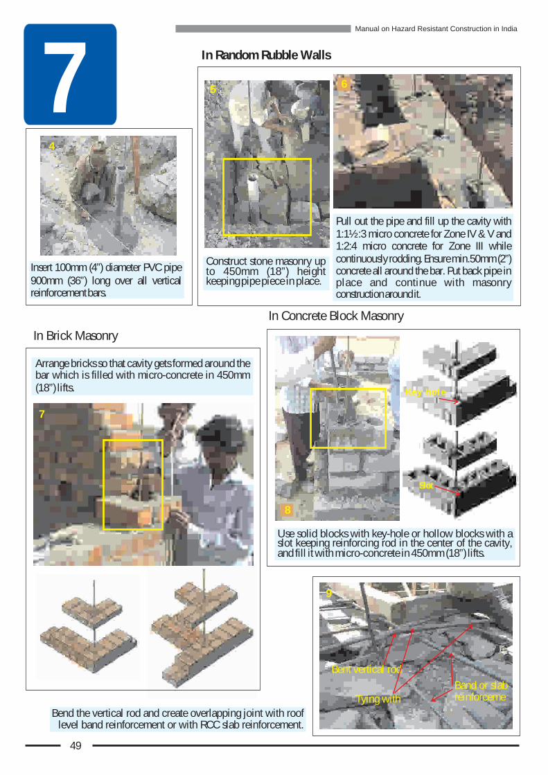
Use solid blocks with key-hole or hollow blocks with a slot keeping reinforcing rod in the center of the cavity, and fill it with micro-concrete in 450mm (18”) lifts.
Bend the vertical rod and create overlapping joint with roof level band reinforcement or with RCC slab reinforcement.
In Random Rubble Walls
Insert 100mm (4”) diameter PVC pipe 900mm (36”) long over all vertical reinforcement bars.
Construct stone masonry up to 450mm (18”) height keeping pipe piece in place.
Pull out the pipe and fill up the cavity with 1:1½:3 micro concrete for Zone IV & V and 1:2:4 micro concrete for Zone III while continuously rodding. Ensure min.50mm (2”) concrete all around the bar. Put back pipe in place and continue with masonry construction around it.
Arrange bricks so that cavity gets formed around the bar which is filled with micro-concrete in 450mm (18”) lifts.
4
5
9
Bent vertical rod
Band or slab reinforcemeTying with
K e y h o l e
Slot
In Brick Masonry
In Concrete Block Masonry
7
6
8
49
Manual on Hazard Resistant Construction in India
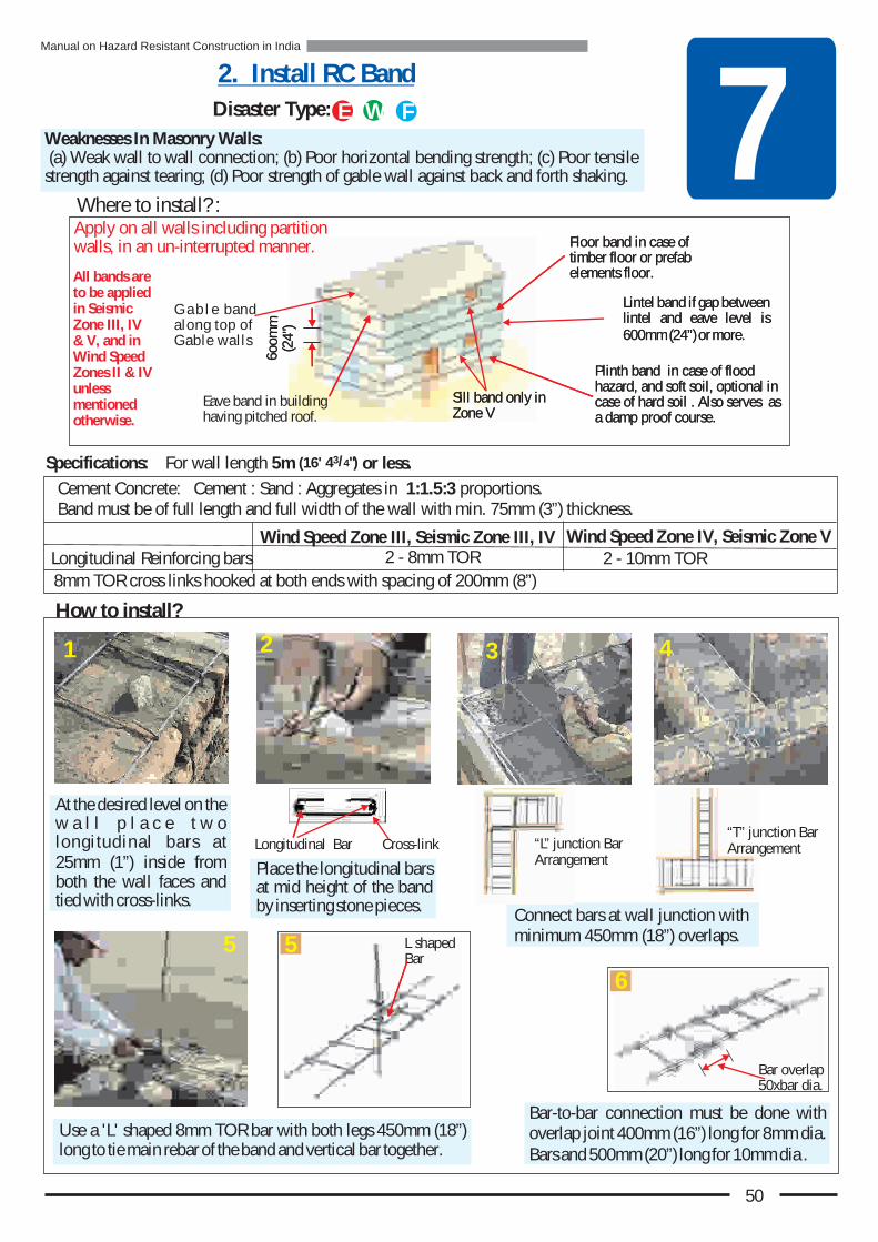
7Weaknesses In Masonry Walls: (a) Weak wall to wall connection; (b) Poor horizontal bending strength; (c) Poor tensile strength against tearing; (d) Poor strength of gable wall against back and forth shaking.
Where to install? :
Cement Concrete: Cement : Sand : Aggregates in 1:1.5:3 proportions.Band must be of full length and full width of the wall with min. 75mm (3”) thickness.
2. Install RC Band
Use a 'L' shaped 8mm TOR bar with both legs 450mm (18”) long to tie main rebar of the band and vertical bar together.
Bar-to-bar connection must be done with overlap joint 400mm (16”) long for 8mm dia. Bars and 500mm (20”) long for 10mm dia .
At the desired level on the w a l l p l a c e t w o longitudinal bars at 25mm (1”) inside from both the wall faces and tied with cross-links.
Place the longitudinal bars at mid height of the band by inserting stone pieces.
Connect bars at wall junction with minimum 450mm (18”) overlaps.
Longitudinal Bar
Wind Speed Zone III, Seismic Zone III, IV Wind Speed Zone IV, Seismic Zone VLongitudinal Reinforcing bars 2 - 8mm TOR 2 - 10mm TOR
8mm TOR cross links hooked at both ends with spacing of 200mm (8”)
Eave band in building having pitched roof.
Floor band timber floor or prefab elements floor.
in case of
Lintel band if gap between lintel and eave level is 600mm (24”) or more.
Plinth band hazard, and soft soil, optional in case of hard soil . Also serves as a damp proof course.
in case of flood
G a b l e band along top of Gable walls
How to install?
1 2 3 4
5
Disaster Type: FWE
Apply on all walls including partition walls, in an un-interrupted manner.
Cross-link
L shaped Bar
Bar overlap 50xbar dia.
5
6
50
All bands are to be applied in Seismic Zone III, IV & V, and in Wind Speed Zones II & IV unless mentioned otherwise.
6oom
m
(24"
)
Specifications: For wall length 5m 3/4(16' 4 ") or less.
Sill band only in Zone V
Floor band timber floor or prefab elements floor.
in case of
Lintel band if gap between lintel and eave level is 600mm (24”) or more.
Plinth band hazard, and soft soil, optional in case of hard soil . Also serves as a damp proof course.
in case of flood
6oom
m
(24"
)
Sill band only in Zone V
“L” junction Bar Arrangement
“T” junction Bar Arrangement
Manual on Hazard Resistant Construction in India

7Provide two bars of same size as that in band and bent into a necessary shape to ensure an overlap of 450mm (18”).
Pour concrete of 1:1.5:3 proportion with rodding. Cure band for fifteen days.
Remember: Make sure the bars in band are not cut in the corner. In an earthquake, band can break at the point where bars are cut.
(3) Timber Band: Ensure proper overlapping joint at corner using 2 or more nails, screws or wood pegs.
Alternatives: Low-cost and simpler options
Connection of Eave to Gable Band:
When lintel band is not installed, bars from lintel are bent upwards and tied to the rebars of eave band. Vertical portion is fully encased in concrete.
Connection of Lintel with Eave Band
Lintel
Eave level band
2. Install RC Band (cont.)
21
7.
Eave level
Lintle Lintle
Eave Band
Eave Band
Gable Band
Junction of both bands
Eave Band
Bars f
or
Gab
l B
and
e
3
(1) Chicken wire mesh or (2) Bamboo ladder encased in 25mm (1”) layer of mud mortar at several levels.
For earthern/adobe walls (Cases A & B) or masonry walls built using clay mud mortar (Case C). Note: Chemical treatment of bamboo and timber will enhance their durability 8 to 10 times.
Case A Case BCase C
51
3
Manual on Hazard Resistant Construction in India
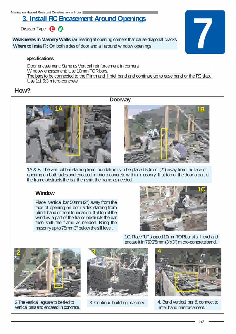
7Weaknesses In Masonry Walls: (a) Tearing at opening corners that cause diagonal cracks
Door encasement: Same as Vertical reinforcement in corners. Window encasement: Use 10mm TOR bars.The bars to be connected to the Plinth and lintel band and continue up to eave band or the RC slab. Use 1:1.5:3 micro-concrete
How?:
1A & B. The vertical bar starting from foundation is to be placed 50mm (2”) away from the face of opening on both sides and encased in micro concrete within masonry. If at top of the door a part of the frame obstructs the bar then shift the frame as needed.
Place vertical bar 50mm (2”) away from the face of opening on both sides starting from plinth band or from foundation. If at top of the window a part of the frame obstructs the bar then shift the frame as needed. Bring the masonry up to 75mm 3” below the sill level.
Window
1C. Place “U” shaped 10mm TOR bar at sill level and encase it in 75X75mm (3"x3") micro-concrete band.
3. Continue building masonry.2.The vertical legs are to be tied to vertical bars and encased in concrete.
4. Bend vertical bar & connect to lintel band reinforcement.
Where to Install? : On both sides of door and all around window openings
Doorway
3. Install RC Encasement Around Openings
1B1A
1C
2 3 4
Disaster Type: WE
Specifications:
52
Manual on Hazard Resistant Construction in India
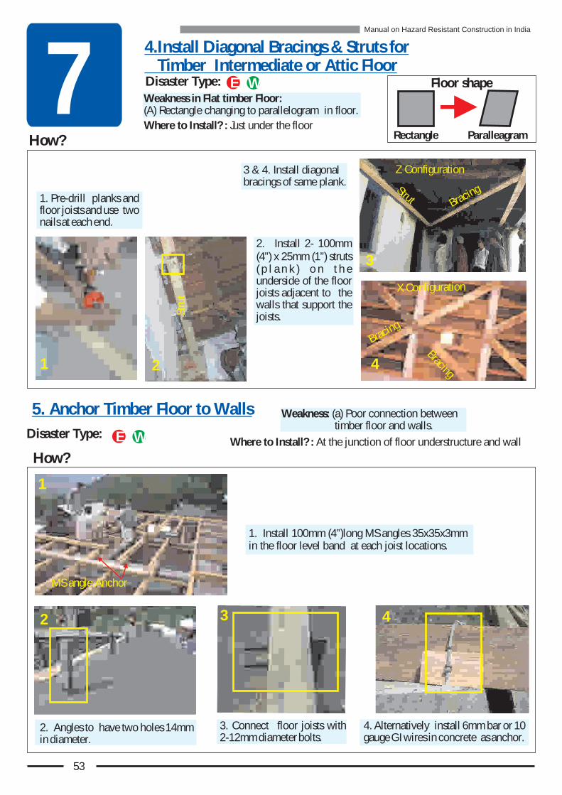
7Where to Install? : Just under the floor
4.Install Diagonal Bracings & Struts for Timber Intermediate or Attic Floor
How?
Weakness in Flat timber Floor: (A) Rectangle changing to parallelogram in floor.
Disaster Type:Where to Install? : At the junction of floor understructure and wall
2. Angles to have two holes 14mm in diameter.
3. Connect floor joists with 2-12mm diameter bolts.
4. Alternatively install 6mm bar or 10 gauge GI wires in concrete as anchor.
1. Install 100mm (4”)long MS angles 35x35x3mm in the floor level band at each joist locations.
1
2 3 4
1. Pre-drill planks and floor joists and use two nails at each end.
3 & 4. Install diagonal bracings of same plank.
1 4
2. Install 2- 100mm (4”) x 25mm (1”) struts ( p l a n k ) o n t h e underside of the floor joists adjacent to the walls that support the joists.
3.3
2.
2
How?
Disaster Type: WE
Weakness: (a) Poor connection between timber floor and walls.
WE
Z Configuration
X Co figur tionn a
Bracing
Bracing
raB
ingc
Strut
rt
Stu
MS angle Anchor
5. Anchor Timber Floor to Walls
Floor shape
Rectangle Paralleagram
53
Manual on Hazard Resistant Construction in India
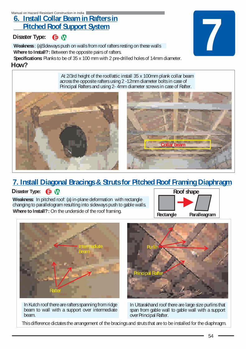
Roof shape
Rectangle Paralleagram
7How?
Weakness: In pitched roof: (a) in-plane deformation with rectangle changing to parallelogram resulting into sideways push to gable walls.
Specifications: Planks to be of 35 x 100 mm with 2 pre-drilled holes of 14mm diameter.Where to Install? : Between the opposite pairs of rafters.
Weakness : (a)Sideways push on walls from roof rafters resting on these walls
6. Install Collar Beam in Rafters in Pitched Roof Support System
7. Install Diagonal Bracings & Struts for Pitched Roof Framing Diaphragm
At 2/3rd height of the roof/attic install 35 x 100mm plank collar beam across the opposite rafters using 2 -12mm diameter bolts in case of Principal Rafters and using 2- 4mm diameter screws in case of Rafter.
Where to Install? : On the underside of the roof framing.
In Kutch roof there are rafters spanning from ridge beam to wall with a support over intermediate beam.
In Uttarakhand roof there are large size purlins that span from gable wall to gable wall with a support over Principal Rafter.
This difference dictates the arrangement of the bracings and struts that are to be installed for the diaphragm.
Principal Rafter
Purlin
Rafter
Intermediate Beam
Disaster Type: WE
WE
Collar beam
Disaster Type:
54
Manual on Hazard Resistant Construction in India
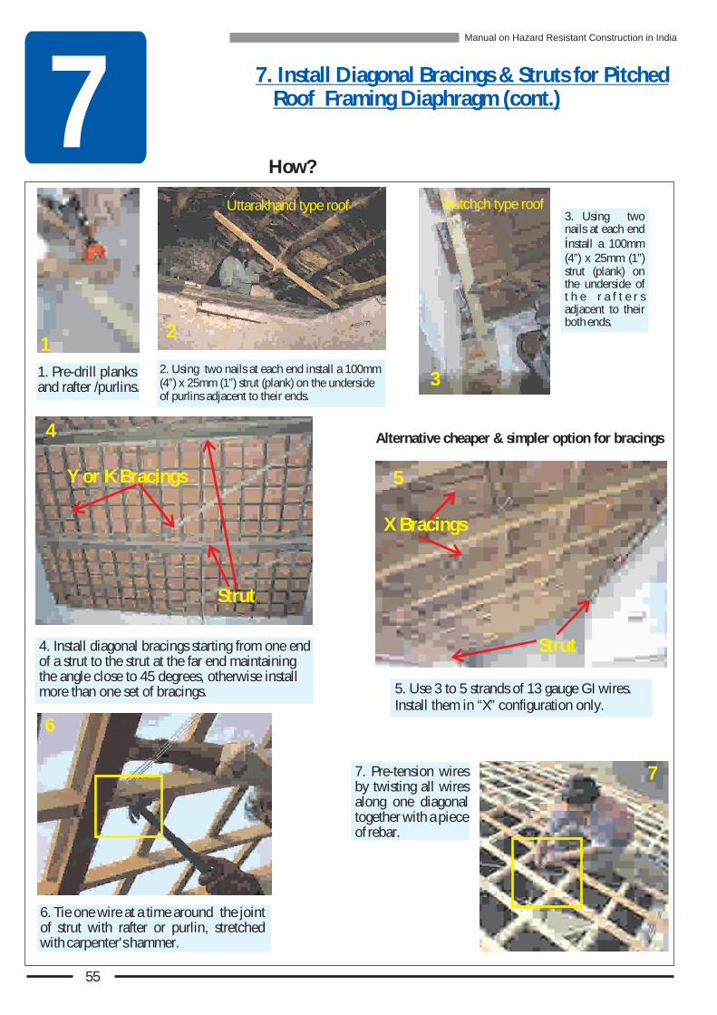
7
1. Pre-drill planks and rafter /purlins.
7. Install Diagonal Bracings & Struts for Pitched Roof Framing Diaphragm (cont.)
How?
Alternative cheaper & simpler option for bracings
7. Pre-tension wires by twisting all wires along one diagonal together with a piece of rebar.
3. Using two nails at each end install a 100mm (4”) x 25mm (1”) strut (plank) on the underside of t h e r a f t e r s adjacent to their both ends.
5. Use 3 to 5 strands of 13 gauge GI wires. Install them in “X” configuration only.
4. Install diagonal bracings starting from one end of a strut to the strut at the far end maintaining the angle close to 45 degrees, otherwise install more than one set of bracings.
6
7
5
Strut
X Bracings
4
Strut
Y or K Bracings
21
2. Using two nails at each end install a 100mm (4”) x 25mm (1”) strut (plank) on the underside of purlins adjacent to their ends.
3
Uttarakhand type roof Kutchch type roof
6. Tie one wire at a time around the joint of strut with rafter or purlin, stretched with carpenter's hammer.
55
Manual on Hazard Resistant Construction in India

7Weakness : (a) Poor connection between roof framing and wall
How?
8. Anchor Pitched Roof Support Structure to Wall
Alternatively, cheaper and simpler options…
Anchor rafters or purlins with eave or gable band in the same way the floor joists are anchored to band
1. MS angle 35x35x3mm 75mm (3”) long installed in eave or gable band for anchoring rafters and purlins.
2. 6mm MS bar installed in Eave level RC Band to anchor purlin or rafter by simply bending over them.
3. Pieces of 10 gauge GI wires attached to reinforcing bars in eave band leaving 300mm (12”)long ends projecting out.
4 & 5. Tie down rafters with two strands of GI wires.
4 .5
a. Anchoring Rafters & Purlins to Eave & Gable Walls
b. Tying Down Roof Projection at Eave Level To Wall
Where to Install? : At the junction of (a) roof framing rafters and eave level walls, & roof purlins and gable walls, (b) roof projection at eave level and wall (in case of Cyclone hazard), (c) roof beams on gable wall.
Install a tie between eave level roof projection & wall below eave level at approximately 45 degrees to wall! Made of 10mm TOR rod, or! MS angle 35x35x3mm, or! 25x100mm timber pieceConnect tie securely at both ends using two or more nails or screws.
For Wind speed Zone IV & V only
Disaster Type: WE
W
21 3
56
Manual on Hazard Resistant Construction in India

7 C. Anchor Ridge beam and Intermediate beams to gable wall
Where to Install? : At the (a) Connections between roof frame elements, namely purlins, rafters and beams, (b) Junction of roofing to roof framing and (c) Junction of roofing with gable wall.
How?
a. Connections between Roof Frame elements, namely purlins, rafters and beams
Install 12mm diameter bolt 250mm (10”)long with a 100x100x5mm MS plate welded at its bottom in the band at the right location.
Once concrete becomes hard place timber beam with a through hole over the bolt and place a washer and a nut to anchor it down.
2
9. Secure Roofing to Roof Frame & Wall
In wind speed area use galvanized metal straps along with 2 nails. Pre-drill pilot holes.
Alternately, cheaper and easier option is tying together of elements with multiple strands of 10 gauge GI wires. Connection of purlins & rafters,
and beam & rafters.
Disaster Type: WE
Weakness in pitched roof: (a) Absence of anchoring of roofing tiles to framing, (b) Weak anchoring of sheeting to framing, (c) Weak anchoring of roofing to gable wall.
1 3
4
1 2 3
57
Manual on Hazard Resistant Construction in India

7b. Secure Roofing to Roof Frame
Hooks must be installed with nut, 6 gauge MS washer followed by washer of Bituminous Felt or Neoprene.
‘U’ hookWind Speed Zone V only
The holes in sheeting must be made in ridges to minimize water leakage.
Secure roof sheeting to purlins using 'J' hooks or 'U' Hooks.
Anchoring Sheeting
Anchoring Roofing Tiles
Anchor lowest row of tiles at e a v e l e v e l with 2- 10 gauge GI wires or 6mm MS rod from one end to the other.
Anchor each tile or every other tile to purlin with GI hooks.
2-10 gauge wires to be taut
Anchor wires or rod to eave-board
W
‘J’ hook
Nut30x30x6mm gauge MS washer
Sealing washerneoprene orbituminous felt
Nut30x30x6mm gauge MS washer
Sealing washerneoprene orbituminous felt
GI Hook
WE
WE
3 4
1 2
58
Manual on Hazard Resistant Construction in India
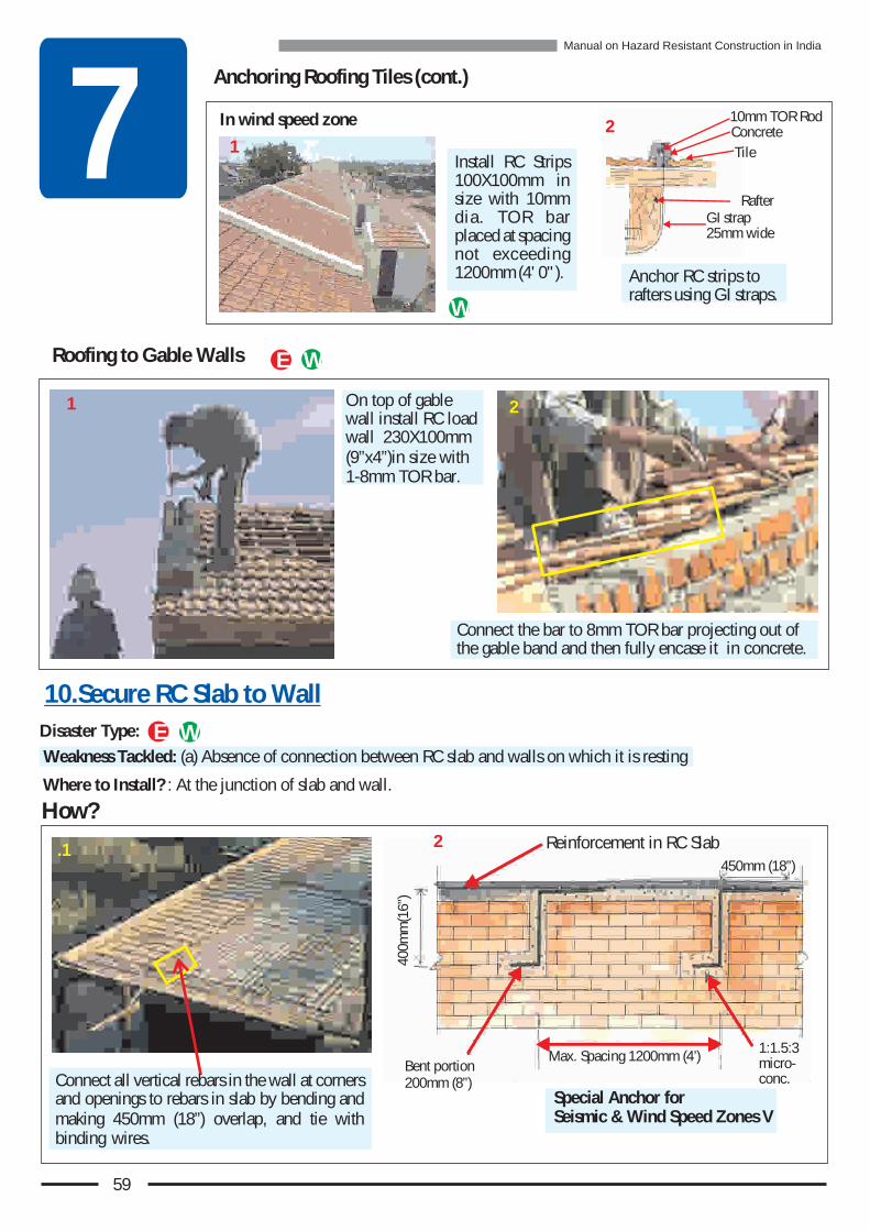
7
On top of gable wall install RC load wall 230X100mm (9”x4”)in size with 1-8mm TOR bar.
Connect the bar to 8mm TOR bar projecting out of the gable band and then fully encase it in concrete.
Where to Install? : At the junction of slab and wall.
How?
Anchoring Roofing Tiles (cont.)
Roofing to Gable Walls
Connect all vertical rebars in the wall at corners and openings to rebars in slab by bending and making 450mm (18”) overlap, and tie with binding wires.
.1
Special Anchor forSeismic & Wind Speed Zones V
Reinforcement in RC Slab
Max. Spacing 1200mm (4’)
400m
m(1
6”)
Bent portion 200mm (8”)
1:1.5:3 micro-conc.
2
450mm (18”)
Install RC Strips 100X100mm in size with 10mm dia. TOR bar placed at spacing not exceeding 1200mm (4' 0" ). Anchor RC strips to
rafters using GI straps.
In wind speed zone
1Concrete
GI strap 25mm wide
Tile
10mm TOR Rod
Rafter
2
1 2
Disaster Type:
W
WE
WE
10.Secure RC Slab to Wall
Weakness Tackled: (a) Absence of connection between RC slab and walls on which it is resting
59
Manual on Hazard Resistant Construction in India

7
Weakness : (a) Doors & windows anchoring to walls weak against suction; (b) Weakness of window glass against air pressure/suction
How?
Anchor door frame with at least 6 holdfasts, and window frame with at least 4 holdfasts.
Hold-fasts to be at least 230mm (9”) long. It must be tied to vertical bar.
! Make smaller glass panes, or! For low cost place plastic
film on glass, or! Install metal screen on the
Provide strong locking arrangement to resist wind suction.
1
3
4
2
Where to Install? : (a) At the junction of timber column and timber beam.
1 2
How? Install knee braces from bottom of beam to face of column.
MS Angle Knee bracesWooden Knee braces
Install one knee brace for each beam resting on column from different directions.
Knee brace connection must be able to take tension and compression.
Knee brace should be heavy enough to resist buckling under pressure.
Install at least two nails at each connection
Disaster Type:
11. Stiffening of Timber Beam to Column Connection
12. Secure Doors & Windows
Disaster Type: W
E
Beam
Column Knee Brace
Column
Beam
rK
nee
Bac
e
Beam
Weakness : (a) Weak connection allows excessive side sway of timber frame that supports the roof or floor.
Where to Install? : (a) At junction of opening frames and walls; (b) Locking arrangement; (c) Glass pane in windows.
60
Manual on Hazard Resistant Construction in India
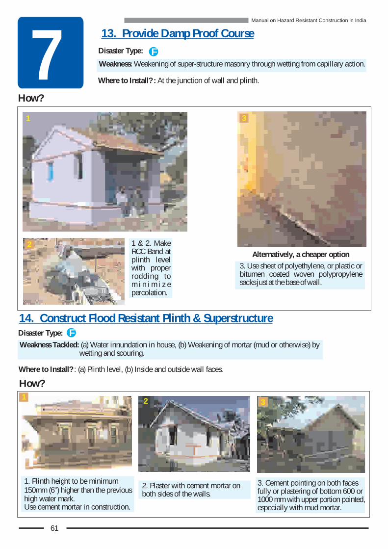
Weakness: Weakening of super-structure masonry through wetting from capillary action.
How?
Weakness Tackled: (a) Water innundation in house, (b) Weakening of mortar (mud or otherwise) by wetting and scouring.
How?
7
2. Plaster with cement mortar on both sides of the walls.
3. Cement pointing on both faces fully or plastering of bottom 600 or 1000 mm with upper portion pointed, especially with mud mortar.
1. Plinth height to be minimum 150mm (6”) higher than the previous high water mark.Use cement mortar in construction.
2
1 & 2. Make RCC Band at plinth level with proper rodding to m i n i m i z e percolation.
3. Use sheet of polyethylene, or plastic or bitumen coated woven polypropylene sacks just at the base of wall.
Alternatively, a cheaper option
Disaster Type:
13. Provide Damp Proof Course
Disaster Type:
14. Construct Flood Resistant Plinth & SuperstructureF
F
1
Where to Install? : At the junction of wall and plinth.
Where to Install? : (a) Plinth level, (b) Inside and outside wall faces.
1 3
2
3
61
Manual on Hazard Resistant Construction in India

et
Dis
as
te
r R
sis
ing F
ea
tu
re
s -
lV
ri
ns
Re
gio
na
a
iat
o
8Four examples are given here to provide guidance on what special disaster resisting features must be included in the construction in Kashmir Vallies, Kutchch, Uttarakhand and Marathwada. Details of all these features are given in Chapter 7.
1.Houses in Kashmir Valley
2. Kutch House
4. Marathwada House3.Uttrakhand House
In the disaster prone areas of India
different building systems are used.
Many of these buildings have been
found to be vulnerable during the
past disasters.
Following are the typical examples of buildings in each of the four regions
62
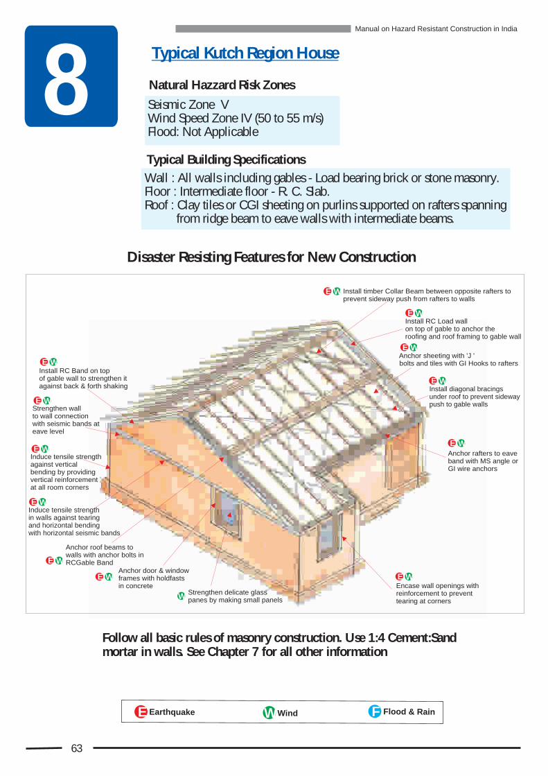
8Wall : All walls including gables - Load bearing brick or stone masonry. Floor : Intermediate floor - R. C. Slab.Roof : Clay tiles or CGI sheeting on purlins supported on rafters spanning from ridge beam to eave walls with intermediate beams.
E rthqu kea a Wind Floo & aind RFWE
Anchor sheeting with 'J ' bolts and tiles with GI Hooks to rafters
Install RC Load wall on top of gable to anchor the roofing and roof framing to gable wall
Install timber Collar Beam between opposite rafters to prevent sideway push from rafters to walls
Anchor rafters to eave band with MS angle or GI wire anchors
Install diagonal bracings under roof to prevent sideway push to gable walls
Encase wall openings with reinforcement to prevent tearing at corners
Strengthen wall to wall connectionwith seismic bands at eave level
Induce tensile strength against vertical bending by providing vertical reinforcement at all room corners
Install RC Band on top of gable wall to strengthen it against back & forth shaking
Anchor roof beams to walls with anchor bolts inRCGable Band
Anchor door & windowframes with holdfastsin concrete
Strengthen delicate glass panes by making small panels
Induce tensile strength in walls against tearing and horizontal bending with horizontal seismic bands
W
WE
WE
WE
WE
WE
WEWE
WE
WE
WE
WE
WE
63
Disaster Resisting Features for New Construction
Typical Kutch Region House
Follow all basic rules of masonry construction. Use 1:4 Cement:Sand mortar in walls. See Chapter 7 for all other information
Natural Hazzard Risk Zones
Seismic Zone VWind Speed Zone IV (50 to 55 m/s) Flood: Not Applicable
Typical Building Specifications
Manual on Hazard Resistant Construction in India

8Wall : Up to eave level - Load bearing brick & stone masonry.Gable walls - Timber laced masonry or timber planks or CGI sheets.Floor : Intermediate and Attic - Timber planks on timber joists.Roof : CGI sheets on timber purlins supported on timber trusses.
Strengthen wall to wall connection with seismic bands at floor and eave level
Induce tensile strength against bending about horizontal axis by providing vertical reinforcement at all room corners
Encase wall openings all around with reinforcement to prevent tearing at corners.
Install diagonal bracingsunder timber floor to prevent in-plane deformation
Anchor floor joists to walls with MS angle or MS rod anchorin RC band
Prevent dampening & erosion of mortar by plastering orpointing of wall
Improve storey-to-storey connectivity by providing vertical reinforcement
Induce tensile strength in walls against tearing and horizontal bending with horizontal seismic bands
Install collar beams to prevent sideway push from rafter to walls
Anchor principal raftersof roof frame to walls with MS angle or MS rodanchors in RC band
Anchor sheeting with 'J ' or ' U ' bolts and tiles with GI hooks to rafters
Anchor door & window frames with holdfasts in concrete.
Prevent flooding of house by building plinth level higher than last high flood level
Protect plinth with cement plaster, or with cement pointing
E
E
E
E
E
E
E
E
E
E
Anchor roof band to walls with vertical rods within masonry
E
E
E
F
F
FF
FF
E
Prevent dampening of mudmortar through Capillary actionby installing damp-proof courseat plinth level.
E rthqu kea a Wind Floo & aind RFWE
64
Typical Kashmir Region House
Natural Hazzard Risk Zones
Typical Building Specifications
Seismic Zone VWind Speed Zone IV (50 to 55 m/s) Flooding : Likely in valleys
Disaster Resisting Features for New Construction
Follow all basic rules of masonry construction. Use 1:4 Cement:Sand mortar in walls. See Chapter 7 for all other information
Manual on Hazard Resistant Construction in India

8Wall : Stone masonry. Roof : Mud on timber deck supported on columns with CGI sheet awnings.
Non-load bearing -
E rthqu kea a Wind Floo & aind RFWE
Encase wall openings with reinforcement to prevent tearing corners.
Install diagonal bracings under timber roof deck to prevent in-planedeformation
Induce tensile strength in walls against tearing and horizontal bending with horizontal seismic bands
Anchor roof joists to RC Band in walls withMS angle or GI wire anchors. Anchor door & window frames
with holdfasts in concrete.Prevent dampening & erosion of mortarby plastering or pointing of wall
Strengthen column-beam connection to resist lateral sway
Place mud layer no thickerthan 200 mm (8") with polythylene water barrier
E
Typical Latur Region House
E
E
E
E
E
E
E
65
Natural Hazzard Risk Zones
Seismic Zone IIIWind Speed Zone II (39to 44 m/s)Flood : Not Applicable Typical Building Specifications
Disaster Resisting Features for New Construction
Follow all basic rules of masonry construction. Use 1:6 Cement:Sand mortar in walls. See Chapter 7 for all other information
Manual on Hazard Resistant Construction in India

8Wall : All walls including gable walls - Load bearing stone masonry.Floor : Intermediate floor - Timber plank on timber joists.Roof : Slate on planks supported on purlins spanning between gable and principle rafters.
Typical Garhwal - Uttarakhand House
Prevent dampening of mudmortar through Capillary actionby installing damp-proofcourse at plinth level.
Strengthen wall-to-wall connection with seismic bands at floor and eave level
Induce tensile strength against vertical bending by providing vertical reinforcement at all room corners
Improve storey-to-storey connectivity by providing vertical reinforcement bonding
Anchor top storey to roof with vertical rod
Induce tensile strength in walls against tearing and horizontal bending with horizontal seismic bands
Install RC Band on top of gable wall to strengthen it against back & forth shaking
Encase wall openings with reinforcement to prevent tearing at corners.
Install diagonal bracings under timber floor to prevent in-plane deformation
Anchor floor joists to RC Band in walls
Install collar beams to prevent sideway push from rafter to walls
Install diagonal bracings under roof to prevent side way push to gable walls Anchor principal rafters
to walls with GI wire orMS angle anchors in RC Band
Anchor door & window frames with holdfasts in concrete.Prevent flooding of house by building
plinth level higher than last high flood level
Protect plinth with cement plaster, or with cement pointing
Prevent dampening & erosion of mortar by plastering or pointing of wall
Anchor purlins to gable wall by GI wire in gable band
Anchor slate to purlins with nails
F
E
E
E
E
F
FF
E
E
E
E
E
E
E
E
E
E
E
E rthqu kea a Wind Floo & aind RFWE
66
Natural Hazzard Risk Zones
Typical Building Specifications
Disaster Resisting Features for New Construction
Follow all basic rules of masonry construction. Use 1:4 Cement:Sand mortar in walls. See Chapter 7 for all other information
Seismic Zone VWind Speed Zone II (39 to 44 m/s)Flood : Not Applicable
Manual on Hazard Resistant Construction in India

Ma
eri
l Q
nt
ti
sf
ta
ua
ie
o
r
Ds
ste
r e
iti
t
re
si
aR
ss
ng
Fe
au
9! Here, for a specific measure of each feature, the quantity of materials required
such as cement, steel bars, sand, aggregates etc. are given.
! The user has to finalize which features he is going to use and determine the quantity for each feature, e.g. The number of running meters of RC Band.
! Next, with that quantity in hand, use the information provided in this chapter.
! Simply multiply measurement of a particular feature to the material quantities given in this Chapter to arrive at the total quantity of materials required.
! To specify quantity in each case the most commonly used measuring systems are adopted to make it easy for user to arrive at the quantity and order the materials.
Item no. 1 Vertical Reinforcing Bar installed within
1masonry and encased in 1:1 /2:3 micro concrete with min. all around concrete cover of 50mm (2”).
Material quantities given below are required for 10 m (32’ 9 ”) length of Vertical Bar 1/2
Steel 6.17 kg. 8.89 kg. 15.80 kg.
16mm TOR12mm TOR10mm TOR
Cement 0.002 Cu.m = 0.65 Bags
Sand 0.033 Cu.m = 0.012 Brass
Aggregates 0.065 Cu.m = 0.023 Brass
Now the reader has understood the disaster resisting features that should be used by him in his area. Next when he plans to use them in new construction, the main question that he will be faced with is “how much quantity of materials are needed” and “how much extra money he will have to spend”.
How to use the information on Material Quantities?:
67
Material quantities are listed for applicable to one or more of the Seismic Zones III, IV and V, and Wind Zones III and IV. The items in which no specific Zones are specified are applicable in all Zones.
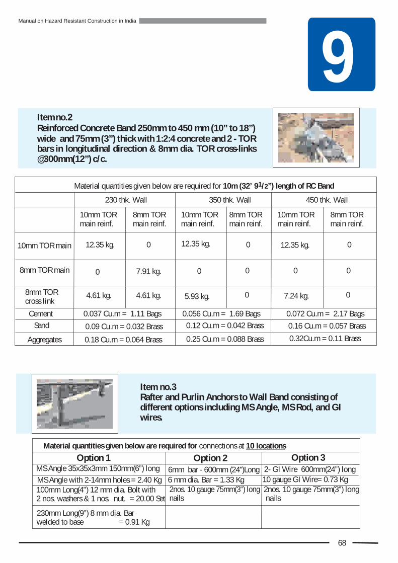
9Item no.2 Reinforced Concrete Band 250mm to 450 mm (10” to 18”) wide and 75mm (3”) thick with 1:2:4 concrete and 2 - TOR bars in longitudinal direction & 8mm dia. TOR cross-links @300mm(12”) c/c.
Material quantities given below are required for connections at 10 locations
2nos. 10 gauge 75mm(3”) long nails
2nos. 10 gauge 75mm(3”) long nails
230mm Long(9”) 8 mm dia. Bar welded to base = 0.91 Kg
100mm Long(4”) 12 mm dia. Bolt with 2 nos. washers & 1 nos. nut. = 20.00 Set
Option 1 Option 2 Option 3MS Angle 35x35x3mm 150mm(6”) long
MS Angle with 2-14mm holes = 2.40 Kg
6mm bar - 600mm (24")Long
6 mm dia. Bar = 1.33 Kg 10 gauge GI Wire= 0.73 Kg
2- GI Wire 600mm(24”) long
Item no.3Rafter and Purlin Anchors to Wall Band consisting of different options including MS Angle, MS Rod, and GI wires.
68
10mm TOR main
8mm TOR main
8mm TOR cross link
Aggregates
Cement
Sand
1Material quantities given below are required for 10m /2 length of RC Band(32’ 9 ”)
10mm TOR main reinf.
0.037 Cu.m = 1.11 Bags
0.18 Cu.m = 0.064 Brass
12.35 kg.
0.09 Cu.m = 0.032 Brass
4.61 kg.
0
230 thk. Wall
8mm TOR main reinf.
4.61 kg.
7.91 kg.
0
10mm TOR main reinf.
12.35 kg.
5.93 kg.
0.056 Cu.m = 1.69 Bags
0.25 Cu.m = 0.088 Brass
0.12 Cu.m = 0.042 Brass
0
350 thk. Wall
8mm TOR main reinf.
0
0
0
10mm TOR main reinf.
12.35 kg.
7.24 kg.
0.072 Cu.m = 2.17 Bags
0.32Cu.m = 0.11 Brass
0.16 Cu.m = 0.057 Brass
0
450 thk. Wall
8mm TOR main reinf.
0
0
0
Manual on Hazard Resistant Construction in India

9
Material quantities given below are required for 10 Manglore Tiles
Manglore Tile Anchors: 3mm dia. Stiff GI Wire Hooks = 10 Nos.
Eave Level Anchor: 2 - 10 gauge GI wire = 1.22 Kg
1 Material quantities given below are required for 10m /2 length of Roof(32’ 9 ”)
Item no. 6Manglore Tile Eave Level Anchor consisting of multiple strands of 10 gauge GI wire.
Item no. 5Manglore Tile Anchors consisting of GI wire clip.
69
12mm dia. bolt 250mm(10”) long with a 100 x 100 x 5mm(4’x4”x1/4”) MS plate welded at its bottom = 20.00 Set
Material quantities given below are required for connection of 10 beams
Item no.4Ridge and Intermediate Beam Anchor to Wall consisting of MS anchor bolt with bearing plate.
Manual on Hazard Resistant Construction in India

70
9
Material quantities given below are required for 10 Sq.m(100Sq.ft. ) of the Floor / Roof area
100mm (4”) x 25mm (1”) strut (timber plank) = 0.124 Cmt. 4 nails / plank -10gauge 100mm(4”) long = 0.215 kg.
Item no. 9
Material quantities given below are required for 10 Sq.m(100Sq.ft. ) of the Roof area
13 gauge GI Wire = 1.04 kg.
10gauge Nails100mm(4”) long = 0.143 kg.100mm (4”) x 25mm (1”) planks = 0.016 Cmt.
Diagonal Bracing of “X” configuration & Struts under Roof Framing with Struts made of timber planks and bracings made of 4 strands of twisted 13gauge GI wires.
Item no. 8Diagonal Bracing of “K” configuration & Struts made of timber planks to be installed under Floor and Roof Framing.
Material quantities given below are required for 10 locations
1 -8mm diameter bolt with 2 washers & 1nut. = 40.00 Set
12mm x 75mm(3”) wood plank collar beam with 4 pre-drilled holes of 8mm diameter. = 10 Nos.
Item no. 7Collar Beam for 1 Rafter pair consisting of timber plank.
Manual on Hazard Resistant Construction in India

’ts
NC
tD
on
- e
w
on
sru
ctio
n 10
1. provide RC columns without providing RC beams.
2. construct fat RC column on top of thin RC column or on top of masonry.
3. construct one column on another with their centre lines not matching.
Never
Never
Never
No RC Beam
Thin Column
Fat Column
Most Commonly Committed Mistakes
Never construct stone masonry by simply stacking one stone over another without proper fitting and using mortar.
Never leave vertical joints unfilled without mortar.
Never connect one wall to another through the use of toothing left out in the wall that is built first.
Care must be taken to follow every rule given in this book in all construction. But in disaster prone areas extra care is needed. The construction photographs shown here are from the Earthquake and Wind Speed Zone V. These are not isolated examples. They represent general scenario in disaster prone areas of India.
Never make any one of these mistake. In a disaster this could be an expensive mistake and could put your life at risk
71
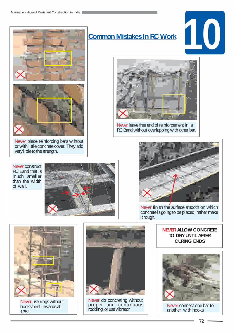
10Common Mistakes In RC Work
Never leave free end of reinforcement iRC Band without overlapping with other bar.
n a
Never connect one bar to another with hooks.
Never use rings without hooks bent inwards at 135°.
NEVER ALLOW CONCRETE TO DRY UNTIL AFTER
CURING ENDS
Never place reinforcing bars wihtout or with little concrete cover. They add very little to the strength.
construct RC Band that is much smaller than the width of wall.
Never finish the surface smooth on which concrete is going to be placed, rather make it rough.
Never do concreting without proper and cont inuous rodding, or use vibrator
Never
72
Manual on Hazard Resistant Construction in India
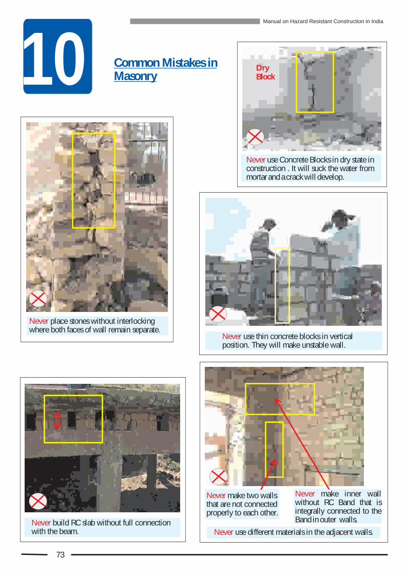
10Never use Concrete Blocks in dry state in construction . It will suck the water from mortar and a crack will develop.
Common Mistakes in Masonry
Never place stones without interlocking where both faces of wall remain separate.
Never make two walls that are not connected properly to each other.
Never make inner wall without RC Band that is integrally connected to the Band in outer walls.Never build RC slab without full connection
with the beam.
Never use thin concrete blocks in vertical position. They will make unstable wall.
Dry Block
Never use different materials in the adjacent walls.
73
Manual on Hazard Resistant Construction in India
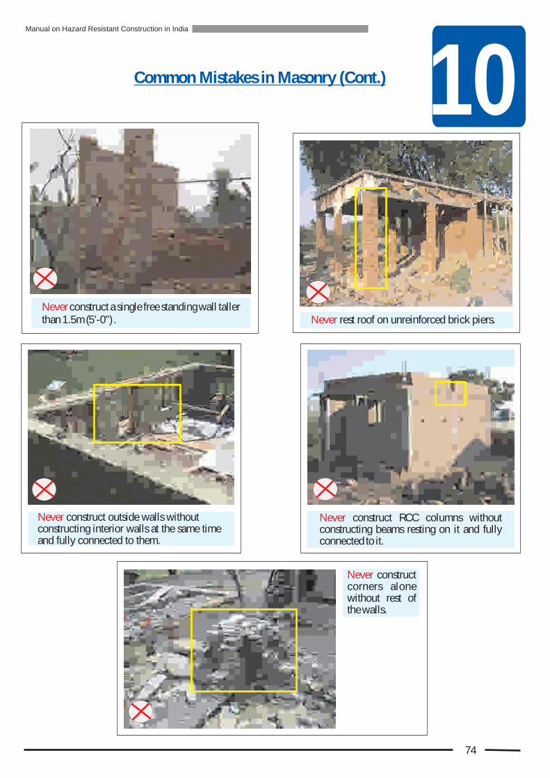
10
Never rest roof on unreinforced brick piers.Never construct a single free standing wall taller than 1.5m (5’-0”) .
Never construct outside walls without constructing interior walls at the same time and fully connected to them.
Never construct RCC columns without constructing beams resting on it and fully connected to it.
Never construct corners alone without rest of the walls.
Common Mistakes in Masonry (Cont.)
74
Manual on Hazard Resistant Construction in India

Re
sto
ra
tio
n P
ro
ce
du
re
s
11Damage Grading and Description
Damage is categorized from G1 to G5
Grade G-1: Slight damage
Restoration1st Step to RehabilitationBringing back a damaged structure to its pre-earthquake state is called Restoration. This results into the restoration of its original strength. Painting, plastering or changing floor tiles is not restoration.
Grade G-2: Moderate damage
Grade G-3: Heavy damage
Large and deep cracks 6mm to10mm (1/4” to 1/2”) wide in walls, widespread cracking of walls and columns, And tilting or collapse of chimneys.
Effect on Structure: The load carrying capacity of the structure is appreciably reduced.
Thin hairline cracks in plaster or in un-plastered masonry that are not deep, and falling of some plaster.
Damage Measurement: Only length of the cracks can be measured.
Effect on Structure: This does not weaken the structure.
Damage Measurement: Cracks are some times across the full thickness of wall. Length and width can be measured.
Effect on Structure: The load carrying capacity of the structure is not reduced appreciably.
Small cracks max. 5mm (1/5”) wide in walls, falling of plaster over large areas, cracking of non-load bearing parts like chimneys, parapets, etc.
Damage Measurement: Cracks are generally across full thickness of wall. Length, width and depth, all three could be measured.
75
Grades as per IS:1893 (Part I)Page 33

11
Grade G-5: Total collapse
Grade G-4: Destruction damage
A large part of the building, or all of it is collapsed.
Gaps in walls, portions of walls about to collapse due to tilting, bulging, delamination or major cracks, or already collapsed.
Effect to Structure: Corner collapse,Building is unsafe and can collapse further.
Damage Measurement: The height, width and depth of the collapsed portion or portions about to collapse are measured.
Ref : NCPDP Shock Table Test Program 2002
76
Manual on Hazard Resistant Construction in India

11 Restoration Procedure for Wall Damage
Damage: Grade G-1 crack Plaster cracking
Damage: Grade G-3 crack Width more than 5mm (1/5”) but less than 10mm (1 /2 ”)
Restoration Procedure: Replaster damaged portion
Make a 'V' notch along the crack Fill up the gap with 1:3 Cement mortar. Finish the restored parts to match the surrounding wall.
Clean it with wire brush, wash and wet with water.
1
3
1 2 3
4
Restoration Procedure: Crack Sealing & Grouting:
4. Fill up hydraulic pump or a simple hand-pump with non-shrink cement slurry.
2. Fix grouting nipples in the 'V' groove at a spacing of 150mm to 200mm, or leave holes at that spacing while sealing the crack with 1:3 cement mortar.
1. Make a 'V' notch along the crack, or widen it with raking tool and clean it with wire brush.
3. Prepare cement slurry 1:1 (non-shrink cement : water)
5. Inject cement slurry into the nipple, or holes starting with the lowest nipple. C u t o f f t h e nipples, seal the holes with 1:3 cement mortar. 5
2
77
Damage : Grade G-2 type crack Width up to 5mm (1/5”)
Manual on Hazard Resistant Construction in India

11
Alternatively, if non-shrink grout or grouting equipment is not available, then..
Alternatively,
Restoration Procedure: Crack Sealing & Splicing:
1 2 3
2-8mm TOR rod
6mm MS rod
10 gauge GI wires
150m
m
150mm 4 A
5 B
600mm
100mm
8mm TOR rod4 B
5 A
Plastered C-Clamp
Plastered WWM Splice
When a crack is large and more quantity of grout is to be pumped then a drum with a nozzle at bottom can be used.
1. Remove plaster, if existing and rake joints up to 12mm depth.
2. Fill the crack with 1:3 cement mortar (cement : fine sand) and install 8mm TOR splice on both faces of the wall.
3. Alternatively install 150mm wide 14 ga. 25x 25mm GI WWM with 100mm long wire nails inserted at spacing of max. 150mm.
5. Plaster over the splice, C clamp or WWM with two 12mm coats of 1:3 cement plaster.
6. Cure it for 15 days.
4. If WWM is not available either use or use splice made of 2-8mm TOR rod.
“C” clamp
Restoration Procedure: Crack Sealing & Grouting: (cont.)
6. Simple hand-pump can be made quickly from PVC pipe pieces of 35mm and 10mm dia., a reducer, and a simple wooden piston.
6 -A
Fill up cement slurry and raise the drum and allow the slurry to flow under gravity pressure in the crack.
35 to 10mm PVC reducer
35mm PVC Pipe
10mm PVC Pipe with cap
MS Rod with wooden piston
8mm TOR Splice
WWM Splice
“C” clamp
Detail of 8mm Tor splice
6 -B
78
Manual on Hazard Resistant Construction in India

11Damage: Grade G-4 Damage - Wall is in imminent danger of collapse or has already collapsed
1. Mark the damaged portion of the wall plus 300mm (1'-0”) extra on all sides.
The photographs below cover a variety of situations with G-4 Damage.
Restoration: Making the wall stable
Procedure: Rebuild entire wall or only the damaged portion of wall.
4 2
2. Support the roof or the floor above; remove the marked portion in stepped manner.
3. Rebuild the wall with the salvaged or new material. Use mortar that is stronger than that used in the existing construction.
4. Once curing is over remove the props and finish the wall to match.
Corner collapsePartially collapsed wallPartially collapsed gable wall
Out of plumb wall Bulging wall Delaminated stone wall
3
1
79
In all of the above situations follow the procedure described
Manual on Hazard Resistant Construction in India

11Restoration Procedures for Roof Damage
1. Restoration of Damaged Roof with CGI /AC Sheet or Clay Tile
A. Damaged timber elements
B. Deformed CGI sheets
2. Restoration of damaged RCC slab
Crack
4 5 6
A. Sealing of fine crack in RC roof
1. Rake the crack with chisel.2. Clean it with wire brush.3. Seal it thoroughly with a sealant
like M-seal using thumb pressure.
1. Clean the crack with wire brush.,2. Fill it with cement : water (1:1) slurry
and cure for at least 15 days, OR use polymer epoxy for grouting.
Seal all open holes with M-seal.Straighten out bent sheets using wooden hammer and 40mm dia. pipe under the sheeting.
Straighten out bent sheets remove any rusted edges around the existing nail / bolt holes with a file or a hammer.
4. Repair the cracked elements of timber by nailing or splicing with metal straps or MS flats. Pre-drill holes in old timber.
5. Replace the severely damaged timber elements of roof.
6. Replace CGI / AC sheets or tiles that were removed.
1. Remove all the roofing from damaged area. 2. If roof damage is because of wall damage then clear the severely damaged
portions of walls and reconstruct them. 3. Repair the cracks and other minor damage.
Damaged roof due to wall collapse
B. Sealing of Moderate (G2) Non Structural crack
80
Manual on Hazard Resistant Construction in India
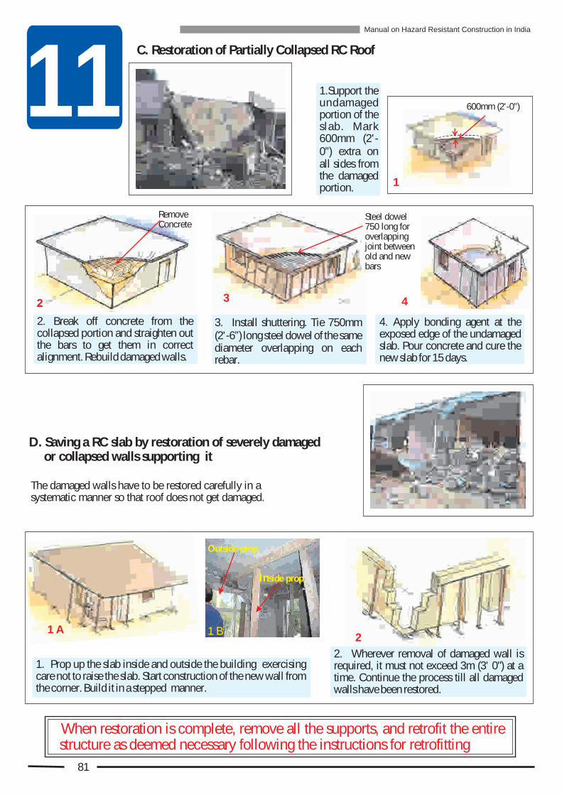
11C. Restoration of Partially Collapsed RC Roof
D. Saving a RC slab by restoration of severely damaged or collapsed walls supporting it
The damaged walls have to be restored carefully in a systematic manner so that roof does not get damaged.
600mm (2'-0”)
1
2 3 4
2
2. Wherever removal of damaged wall is required, it must not exceed 3m (3' 0") at a time. Continue the process till all damaged walls have been restored.
1. Prop up the slab inside and outside the building exercising care not to raise the slab. Start construction of the new wall from the corner. Build it in a stepped manner.
When restoration is complete, remove all the supports, and retrofit the entire structure as deemed necessary following the instructions for retrofitting
2. Break off concrete from the collapsed portion and straighten out the bars to get them in correct alignment. Rebuild damaged walls.
3. Install shuttering. Tie 750mm (2'-6”) long steel dowel of the same diameter overlapping on each rebar.
4. Apply bonding agent at the exposed edge of the undamaged slab. Pour concrete and cure the new slab for 15 days.
1.Support the undamaged portion of the slab. Mark 600mm (2'-0”) extra on all sides from the damaged portion.
Remove Concrete
Steel dowel 750 long for overlapping joint between old and new bars
1 A 1 B
Outside prop
Inside prop
81
Manual on Hazard Resistant Construction in India

Re
fittin
g M
ea
stro
ure
s
12WHAT IS RETROFITTING?! It is possible to reduce the vulnerability of an existing unsafe building. There are
simple ways to do this. It is called Retrofitting.! Retrofitting means preparing a structure in a scientific manner to withstand the forces
of a natural hazard that may occur in future. This needs to be done on all structures
that are found to be vulnerable, whether they are damaged or not.! It is generally the most economical and fastest way to achieve the safety of the
people who occupy the vulnerable building.
The advantages of retrofitting over replacing an existing building for safety against future disasters are:! Retrofitting can be done in phased manner depending upon the availability of funds
and time. So it is not necessary to retrofit the whole structure in one go.! Retrofitting eliminates the need for a temporary shelter since retrofitting can be taken
up in a few rooms at a time.! Retrofitting eliminates the cost of total demolition and removal of debris from
demolition.! Retrofitting can save most of the improvements carried out in the building. There is no
need to redo all of it.
Uttarakhand House Kutchch House
Kashmir House
Preparing for Natural hazards like Earthquake, Cyclone and Floods:
All these houses and thousands more in all disaster prone areas of the country are vulnerable to future disasters. They all cannot be demolished and rebuilt. So for the safety of their occupants they need to be retrofitted.
It is neither possible nor economically viable to demolish all existing vulnerable structures in disaster prone areas. It would be best to upgrade their strength (i.e. retrofit them) to save them from damage and destruction in future.
Advantage of Retrofitting
82

12RETROFITTING MEASURES FOR VULNERABLE EXISTING BUILDINGS IN DISASTER PRONE AREAS
If a building is not designed and constructed to resists the forces of expected natural hazards, it must be strengthened by introducing Retrofitting Measures as shown below to eliminate all the weaknesses present in the building as shown in Chapter 4.
Remember:Any vulnerable part of a building will benefit from the retrofitting measure only if the measure is securely bonded to that part of the building where it is applied.
Strengthen masonry column with jacketing
Encase wall opening with reinforcement or reduce the number or size of openings
Provide in-plane bracings under timber floor
Induce tensile strength against vertical bending by providing vertical reinforcement at all inside and outside corners
Strengthen corners with seismic belts at middle floor and eave level
Strengthen gable wall byinstalling sloping belt on gable wall
Install diagonal bracings
Install diagonal collar beams
Anchor floor joists to walls with brackets
Improve story- to- story connectivity by providing vertical reinforcement
Induce tensile strength in walls against in-plane tension and horizontal seismic belts
Provide bond elements in stone wall
Anchor downR C Slab to wall with proper connection with Verticalreinforcement
Anchor roof truss to walls with brackets
r kEa thqua e Wind F & alood R inE W F
WE
WE
WE
WE
WE
WE
E
WE
WE
E
WE
WE
WE
WE
83
Manual on Hazard Resistant Construction in India
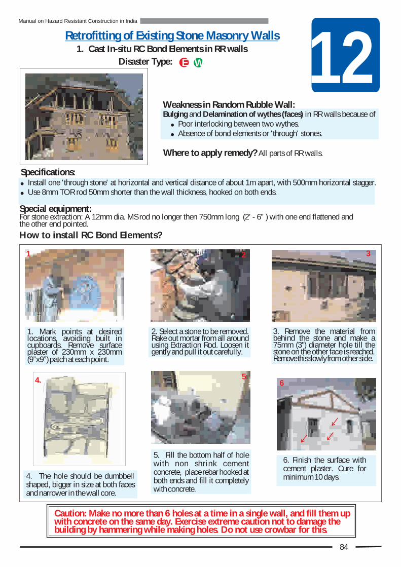
12Retrofitting of Existing Stone Masonry Walls
Weakness in Random Rubble Wall: Bulging and Delamination of wythes (faces) in RR walls because of
! Poor interlocking between two wythes.! Absence of bond elements or 'through' stones.
Where to apply remedy? All parts of RR walls.
Specifications: ! Install one 'through stone' at horizontal and vertical distance of about 1m apart, with 500mm horizontal stagger. ! Use 8mm TOR rod 50mm shorter than the wall thickness, hooked on both ends.
How to install RC Bond Elements?
Caution: Make no more than 6 holes at a time in a single wall, and fill them up with concrete on the same day. Exercise extreme caution not to damage the building by hammering while making holes. Do not use crowbar for this.
1. Cast In-situ RC Bond Elements in RR walls
Disaster Type:
1 2
5 6
3
Special equipment:For stone extraction: A 12mm dia. MS rod no longer then 750mm long (2’ - 6” ) with one end flattened andthe other end pointed.
WE
1. Mark points at desired locations, avoiding built in cupboards. Remove surface plaster of 230mm x 230mm (9”x9”) patch at each point.
2. Select a stone to be removed. Rake out mortar from all around using Extraction Rod. Loosen it gently and pull it out carefully.
3. Remove the material from behind the stone and make a 75mm (3") diameter hole till the stone on the other face is reached. Remove this slowly from other side.
5. Fill the bottom half of hole with non shrink cement concrete, place rebar hooked at both ends and fill it completely with concrete.
4. The hole should be dumbbell shaped, bigger in size at both faces and narrower in the wall core.
6. Finish the surface with cement plaster. Cure for minimum 10 days.
4.
84
Manual on Hazard Resistant Construction in India
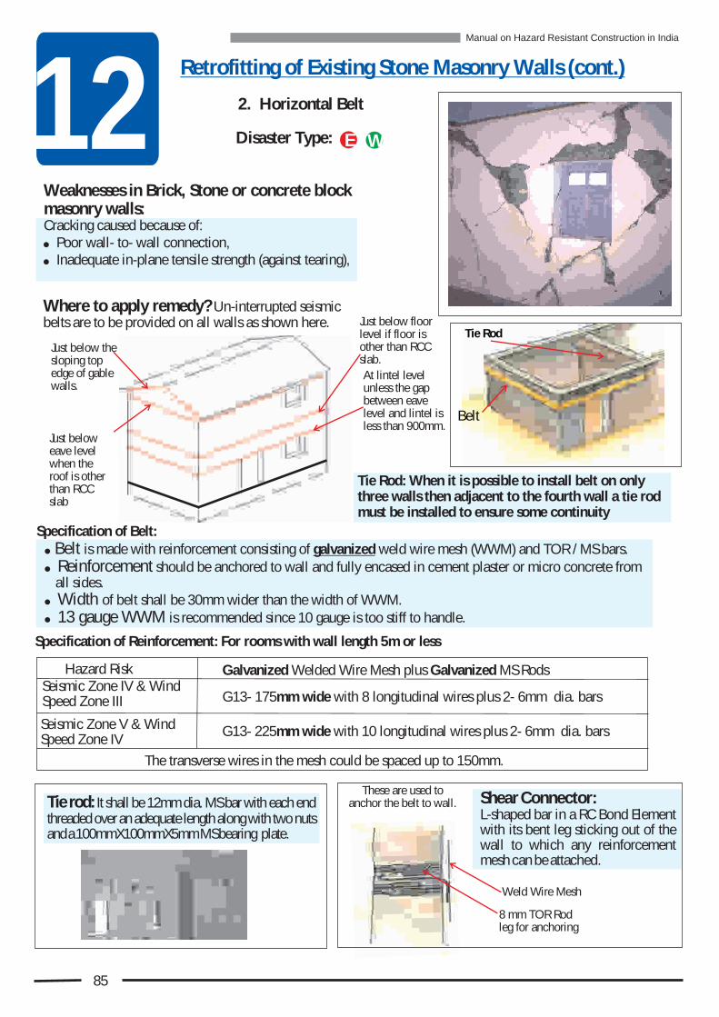
12Retrofitting of Existing Stone Masonry Walls (cont.)
2. Horizontal Belt
Weaknesses in Brick, Stone or concrete block masonry walls: Cracking caused because of: ! Poor wall- to- wall connection,! Inadequate in-plane tensile strength (against tearing),
! Belt is made with reinforcement consisting of galvanized weld wire mesh (WWM) and TOR / MS bars.! Reinforcement should be anchored to wall and fully encased in cement plaster or micro concrete from
all sides.! Width of belt shall be 30mm wider than the width of WWM.! 13 gauge WWM is recommended since 10 gauge is too stiff to handle.
Specification of Reinforcement: For rooms with wall length 5m or less
Tie rod: It shall be 12mm dia. MS bar with each end threaded over an adequate length along with two nuts and a 100mmX100mmX5mm MS bearing plate.
Disaster Type:
Where to apply remedy? Un-interrupted seismic belts are to be provided on all walls as shown here.
WE
At lintel level unless the gap between eave level and lintel is less than 900mm.
Just below floor level if floor is other than RCC slab.
Just below the sloping top edge of gable walls.
Specification of Belt:
Weld Wire Mesh
Shear Connector: L-shaped bar in a RC Bond Element with its bent leg sticking out of the wall to which any reinforcement mesh can be attached.
These are used to anchor the belt to wall.
The transverse wires in the mesh could be spaced up to 150mm.
Seismic Zone IV & Wind Speed Zone III
Hazard Risk
Seismic Zone V & Wind Speed Zone IV
Galvanized Welded Wire Mesh plus Galvanized MS Rods
G13- 175mm wide with 8 longitudinal wires plus 2- 6mm dia. bars
G13- 225mm wide with 10 longitudinal wires plus 2- 6mm dia. bars
Just below eave level when the roof is other than RCC slab
Tie Rod: When it is possible to install belt on only three walls then adjacent to the fourth wall a tie rod must be installed to ensure some continuity
85
8 mm TOR Rod leg for anchoring
Belt
Tie Rod
Manual on Hazard Resistant Construction in India

12How to install WWM Belt?
4. Rake all the mortar joints to the depth of 15mm (5/8") using electric grinder.
6. Cut weld wire mesh as required.
9. In brick or concrete block wall use 100mm (4”) to 150mm (6”) long wire nails driven in to mortar joints, at 300mm (12”) spacing in a staggered fashion in two rows.
10. In case of rubble walls install Cast in-Situ RC shear connectors with bar sticking out every 1.25m (4'0”). Attach WWM to the bar with binding wire. In addition use 100mm long square headed nails at 150-300mm spacing.
8. Install WWM on the prepared surface.
11. Provide spacers 15mm (1/2”) thick between the wall and the mesh.
1. Mark the top & bottom edges of belt on wall using string and tube level.
2. Using electric grinder, or chisel, cut the plaster along the markings.
7. Attach precut 6mm reinforcing bars with binding wires.
5. In case of no electricity, use chisel. Clean the surface with wire brush and water.
12
3
45
6
8
109
11
7Install Shear Connectors
86
3. Remove the plaster from the marked area exposing wall surface.
Manual on Hazard Resistant Construction in India

12
14.B Tighten the Tie rod, after finishing the belt, with the help of two nuts at each end. Place 75x75x5mm bearing plate in front of the nut before tightening.
1 5 . W h e r e t h e b e l t a l ignment crosses an opening take the belt up or down around the opening.
17. Cure the plaster for 15 days.
14.A Tie rod must be installed level from one wall to the opposite wall going clear through a conduit placed in both walls and through the belts.
! All tie-rods must be in place, before plastering the belt.
! Tie-rods must be level! Tie rods must have
approximately 2.5m (8' 2") vertical clearance from the floor. In the absence of such clearance install pilasters to create additional support to the walls.
! Tie-rod must be taut to be
15 B15 A
16
16. Place plaster in two coats, each 12mm (1/2") thick at an interval of 1 to 2 hours to provide 16mm (5/8") cover over the reinforcement.
14 B
P r o v i d e t h e addi t ional shear reinforcement shown here in the vertical leg of the belt.
Vertical leg of Belt
Special Shear Reinforcement
17
14 A
12. Ensure continuity of reinforcing bars as well as of WWM through lap joints minimum 300mm (12”) long.
12 A
Bar v r a O e l p
12 BWWM Overlap
13.
13. Splash the exposed wall surface with water and apply neat cement slurry followed by first coat of cement : sand (1:3) plaster.
13
87
Manual on Hazard Resistant Construction in India

3. Vertical Reinforcement
Weaknesses in brick or stone masonry walls : ! Poor storey- to- storey connection.! Poor wall to roof connection.
Where to apply remedy? At all wall- to- wall junctions and at other locations in walls from foundation to roof.
Options of Vertical Reinforcement:A. Single reinforcing bar B. Vertical Belt with WWM and reinforcing bars.
Specifications:1A. Bar or WWM belt sizes are given here for walls 5m. In length or shorter.
B. Vertical Belt with Welded Wire Mesh & Bars
Note: WWM made of 13 gauge wires is recommended here since 10 gauge wire mesh is difficult to handle because of its stiffness.
*** : For all other situations see National Disaster Management Division, Govt. of India Guidelines or appropriate National Building Codes.
Disaster type:
At all junctions of walls (Corners).
To be applied in all buildings in Seismic Zones IV & V & in Wind Speed Zone III & IV, and in 2 and 3 storey buildings in Seismic Zone III.
12
*** Single Vertical Reinforcing TOR Bar Size
Zone IV Zone V
One
TwoGround Upper
Ground
Storey
10
1012
12
1216
WWM G13B
No. of storeys
One Two
Ground
UpperGround
Storey
1010
14
300300
400
Weld Mesh - N = No. of longitudinal wires in mesh; B = Width of finished belt ***All Reinforcement in the belt should be Galvanized.
WWM G13N N B
2 - 6mm dia.40014
4001440014
6 - 6mm dia.
WE
88
In all storeys
No. of storeys
Zone III
Wind Speed Zone
Seismic ZonesZone III Zone IV
Ground
Three Upper Top 10
1012
10
1212
12
1616
Seismic Zones IVWind Speed Zone IVSeismic Zones V
Wind Speed Zone IIIAdditional Bars
Three
Ground Upper Top 10
14
14
300400
400
14
1414
400
400400
6 - 6mm dia.
Manual on Hazard Resistant Construction in India

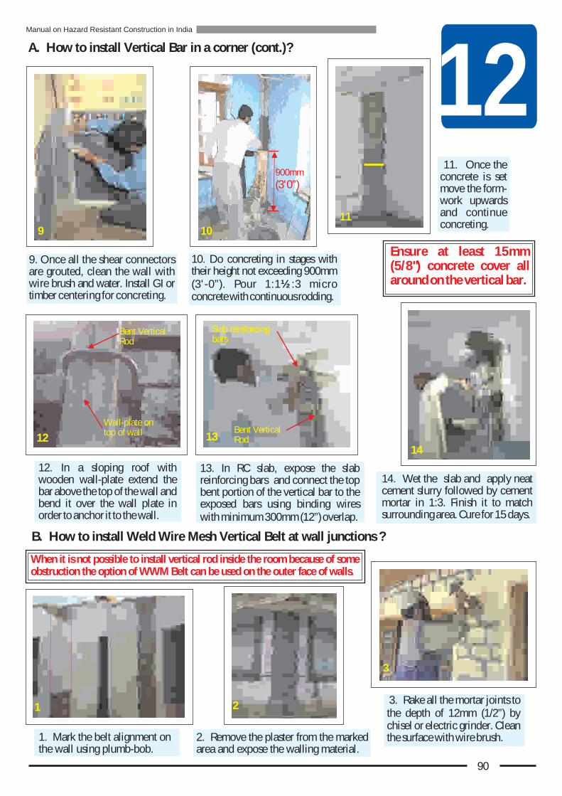
12
9. Once all the shear connectors are grouted, clean the wall with wire brush and water. Install GI or timber centering for concreting.
11. Once the concrete is set move the form-work upwards and continue concreting.
13. In RC slab, expose the slab reinforcing bars and connect the top bent portion of the vertical bar to the exposed bars using binding wires with minimum 300mm (12”) overlap.
12. In a sloping roof with wooden wall-plate extend the bar above the top of the wall and bend it over the wall plate in order to anchor it to the wall.
10. Do concreting in stages with their height not exceeding 900mm (3'-0”). Pour 1:1½:3 micro concrete with continuous rodding.
14. Wet the slab and apply neat cement slurry followed by cement mortar in 1:3. Finish it to match surrounding area. Cure for 15 days.
B. How to install Weld Wire Mesh Vertical Belt at wall junctions ?
1. Mark the belt alignment on the wall using plumb-bob.
3. Rake all the mortar joints to the depth of 12mm (1/2”) by chisel or electric grinder. Clean the surface with wire brush.
Ensure at least 15mm (5/8") concrete cover all around on the vertical bar.
14
11
9
2. Remove the plaster from the marked area and expose the walling material.
2
3
A. How to install Vertical Bar in a corner (cont.)?
When it is not possible to install vertical rod inside the room because of some obstruction the option of WWM Belt can be used on the outer face of walls.
1
Wall-plate on top of wall
Bent Vertical Rod
12
Slab reinforcing bars
Bent Vertical Rod13
900mm
(3'0”)
10
90
Manual on Hazard Resistant Construction in India

125. Prepare the mesh straps of required length and and width and attach to it the precut 6mm bars with binding wires.
4. At the base excavate 400X150mm pit 300mm deep to anchor WWM in concrete.
Separate mesh from wall by placing 15mm (5/8") thick spacers
7. In RR walls also use Cast in-Situ RC Shear Connectors with 'L' shaped dowel bar to anchor the WWM.
9. Ensure continuity of WWM and bars through overlap joints. The minimum overlap shall be 300mm (12”).
11. After 1 to 2 hours apply second layer of plaster with the same mix to provide 16mm (5/8”) cover over the reinforcement. Cure for 15 days.
8. Shear connectors are to be installed at a maximum spacing of 600mm (24”). Once the concrete hardens, attach WWM to it with binding wire.
10. Splash the exposed wall surface with water. While still wet, apply neat cement slurry followed by first coat of cement-sand (1:3) plaster of 12mm (1/2”) thickness.
B. How to install Weld Wire Mesh Vertical Belt at wall junctions (cont.)?
6
7
10
11
5
6. Install ready WWM strap. Use 100mm (4”) long wire nails in bricks and square headed nails in stone at 300mm (12”) spacing in staggered manner to anchor it.
Shear connector
8
WWM overlap
9
4
Pit
91
Manual on Hazard Resistant Construction in India

124. Opening Encasement With Belt
Weaknesses in Masonry Walls: Diagonal cracking at openings because of:! Capacity of wall to withstand tension reduced by
door and window openings.
Specification of belt:A. Galvanized 10 Gauge WWM - No. of wires = 10; Mesh width =
225mm; Belt width = 280mm. Alternatively, for easier handling:B. Galvanized 13 Gauge WWM - Plus 2-6mm dia. Galv. MS Bar.C. If right WWM not available then use 8mm TOR rods with
equivalent area of steel with 13 g GI wire tied crisscross.
How to install Encasement Belt around opening?
1.Demarcate the belt around the openings. If lintel belt is installed, the encasement belt is required only on the side and under the window openings, and only on sides for door.
The installation procedure is exactly same as that used for the horizontal and vertical seismic belt.
4.Belts on all sides of encasement must overlap at corners.
6. Merge two vertical belts in case the spacing between two openings is less than 560mm.
5.The belts on top sides must overlap with the lintel level belt.
Where to apply remedy? On one face of a wall around every opening for door, and window
lintel belt
Encasement belt1
23
4 5 6
13 Gauge WWM
2 - 6mm Galv. MS Rods
Option B
6 Wires
13 Gauge wires
2 - 8mm TOR Rods
Option C
8mm TOR Rod
150mm (6")
Disaster type: WE
92
Manual on Hazard Resistant Construction in India

125. Diagonal Braces & Struts in Timber Floor/ Flat Roof Deck
Weakness in Timber Floor/ Flat Roof : Weakness against sideway forces causing distortions (rectangle becoming parallelogram) in floor / roof
Specification : The timber plank for bracings and struts : 100mm (4”) X 25mm (1”)
How to install timber struts and braces under flat deck?
1. Install 2-100mm (4”) x 25mm (1”) struts (plank) on the underside of the floor beams next to where they are resting on walls with two nails/ screws at each end.
3. Install bracings in same way. Adopt “K” or “X”arrangement so that the angle between bracing and struts is close to 45 degrees.
4.Install more sets of bracings to cover more area of the deck.
5. Instead of two nails or screws for a stronger connection use 2 bolts with 3mm thick steel gusset plate.
2. Pre-drill these planksto prevent splitting
6. Collar Beam for Rafters in Pitched Roof Understructure
Weakness in Sloping Roof :Sideways push on walls from roof rafters resting on them because of:! Flexibility in roof structure.
Where to apply the remedy?Between the opposite pairs of rafters.
How to install Collar Beam / Horizontal Tie?
1Specifications: Use pre- drilled Planks 35x100mm (1 /2” x 4”) in
Use 2-10 g 75mm long wire nails or 2- 5mm bolts for fixing plank to the rafter at each end.
Floor deck damage - Loosening of joints
Where to apply remedy? At the underside of floor and roof
2
4
6
Do not keep bracings too long. If possible nail them to each floor joist.
Install Collar Beams as shown above. Ensure proper level using water tube.
H
H/3
2H/3Rafters
Collar Beam
Disaster type:
Disaster type: WE
X - Bracing
BracingStrut
3
K - Bracing
Floor joists
Bracing
Strut
Two nails Min.
1
Bracing
Strut
Two Bolts
Gusset Plate
5
WE
93
Manual on Hazard Resistant Construction in India
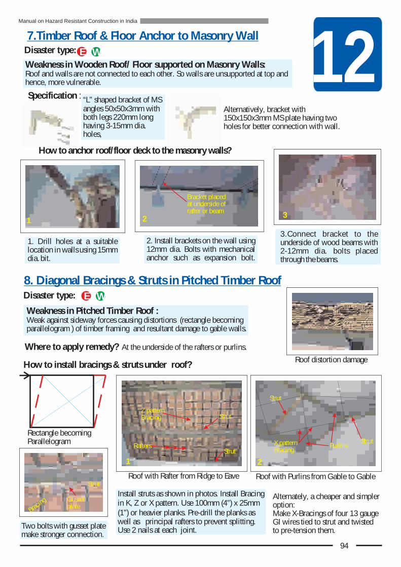
12Weakness in Wooden Roof/ Floor supported on Masonry Walls:Roof and walls are not connected to each other. So walls are unsupported at top and hence, more vulnerable.
How to anchor roof/floor deck to the masonry walls?
2. Install brackets on the wall using 12mm dia. Bolts with mechanical anchor such as expansion bolt.
3.Connect bracket to the underside of wood beams with 2-12mm dia. bolts placed through the beams.
8. Diagonal Bracings & Struts in Pitched Timber Roof
Weakness in Pitched Timber Roof : Weak against sideway forces causing distortions (rectangle becoming parallelogram ) of timber framing and resultant damage to gable walls.
Where to apply remedy? At the underside of the rafters or purlins.
How to install bracings & struts under roof?
Install struts as shown in photos. Install Bracing in K, Z or X pattern. Use 100mm (4”) x 25mm (1”) or heavier planks. Pre-drill the planks as well as principal rafters to prevent splitting. Use 2 nails at each joint.
Two bolts with gusset plate make stronger connection.
Alternately, a cheaper and simpler option:Make X-Bracings of four 13 gauge GI wires tied to strut and twisted to pre-tension them.
Specification : “L” shaped bracket of MS angles 50x50x3mm with both legs 220mm long having 3-15mm dia. holes,
Alternatively, bracket with 150x150x3mm MS plate having two holes for better connection with wall.
Disaster type:
Bracket placed at underside of rafter or beam
Disaster type:
1 2 3
Rectangle becoming Parallelogram
Roof distortion damage
Roof with Purlins from Gable to GableRoof with Rafter from Ridge to Eave
g
Bracin
Strut
Gusset plate
7.Timber Roof & Floor Anchor to Masonry Wall
1. Drill holes at a suitable location in walls using 15mm dia. bit.
Strut
Strut
1
Rafters
Z pattern Bracing
StrutX pattern Bracing
2
Purlins
Strut
WE
WE
94
Manual on Hazard Resistant Construction in India

12
10. Jacketing of Masonry Column
Disaster type:
Weakness in Beam-to-Column Connection:Weak flexible connection allows excessive sway of timber frame that results in damage to walls.
How to install Knee Braces?
Install one knee brace for each beam resting on column from different direction.
Knee brace can be made of MS Angles, MS Pipes or timber.
Knee brace connection to column and beam must be able to take tension and compression.
Knee brace should be heavy enough to resist buckling under pressure.
Knee Brace
11. Anchoring Roofing Tiles & Sheeting to UnderstructureWeakness in Tile Roofing:Absence of anchoring results in tiles and sheeting getting blown off.
How to anchor roof tiles and sheeting to understructure?Disaster type:
I n s t a l l R C S t r i p s 100X100mm with 10mm dia TOR bar at max. spacing 1200mm.
Install two 10 ga. GI wires on the lowest row of tiles from one end to other.
Install a GI wire hook unde r eve ry t i l e attaching it to purlin.
Install U- hooks to a n c h o r s h e e t roofing to purlins.
Details for all these items are given in Chapter 7 on “New Construction”
Disaster type:
Weakness in Masonry Column:Bending of column by lateral forces causes cracking because column has no ductility.
How to Jacket a column?
Remove plaster and rake the joints.
Install 8mm TOR shear connectors in pre-drilled holes in columns for ancho-ring 8mm TOR verti-cal rods to them.
Cover all reinforcement including joint at top with 1:4 cement mortar.
9. Knee Braces at Beam-Column joint
Beam
Column
Retrofitted Roof Deck
WE
Fill holes with non-shrink grout.
E
WE
At top connect the bars with rebars of slab or beams with adequate overlap.
Install two 8mm TOR rods on each face along with 6mm r ings a t 300mm c/c.
95
Manual on Hazard Resistant Construction in India

a
un
es
oa
in
Ma
te
ri
lQ
atit
is -
Re
tr
to
&t
ot
ne
su
e R
er
fiti
g M
ar
s
13Here for a specific quantity of each feature the quantities of material required such as cement, steel bars, sand, aggregates etc. are given.
The user has to finalize which features he is going to use and determine the quantity of each feature.
Next, with that quantity in hand use the information provided in this Chapter.
Simply multiply quantity of a particular feature to the material quantities provided in this Chapter to arrive at the total quantity of material required.
For each material quantity the commonly used measuring systems are adopted to make it easy for user as well as for ease of ordering the materials.
By now the reader must have understood the retrofitting measures that are necessary in his area. After selection of the measures to retrofit a building the main question that he will be faced with is “what quantity of materials are needed” and “how much money he will have to spend”.
How to use the Material Quantity information? :
96
Material quantities listed here are applicable to one or more of the Seismic Zones III, IV and V, and Wind Zones III and IV as indicated in Chapter 11 & 12.
Restoration Features
G-1 & G-2 Crack sealing with 1:3 Cement Sand mortar.
Material quantities: F or 10m length of Crack 0.004 Cu.m = 0.13 Bags
0.01 Cu.m = 0.003 BrassCementSand
Item no.1.
G-3 Crack grouting using appropriate grouting plasticizer in (a) 350mm thick Brick wall with 30% cavity in crack and (b) 450mm thick UCR wall with 150% cavity.
Material quantities: F 1or 10m (32' 9 /2") length of Crack
UCR Masonry 0.01 Cu.m = 0.2 Bags 0.04 Cu.m = 1.2 BagsSand 0.01 Cu.m = 0.03 Brass
Brick Masonry
0.03 Liter 0.2 LiterGrouting Plasticizer 0.013 Cu.m = 0.01 Brass
Cement
Item no. 2.
Crack Stitching Strap 280 mm wide with 250 mm wide WWM having 9 - 13 gauge wires longitudinally and cross wires at spacing of 75mm and covered in 35mm thick cement mortar.
Material quantities: F 1or 10m (32' 9 /2") length of Crack stitching
= 2.3 Sq.m = 4.5 kg.
Galvanized WWM -13gauge 25mmx75mm5mm thk. 100mm (4”) long Galvanized Nails with washer
= 0.1 Cu.m = 0.03 Brass= 0.03 Cu.m = 0.9 Bags
Item no. 3.
CementSand

13
Vertical bar bottom anchor 450x300x300mm (18"x12"x12") filled with 1:3:6 micro concrete.
Vertical bar RCC slab roof anchor covered in 1:1½ :3 micro concrete or Cement Mortar (1:3).
Cement = 0.01 Cu.m = 0.25 BagsSand = 0.01 Cu.m = 0.004 BrassAggregates = 0.02 Cu.m = 0.01 Brass
Material quantities: for 10 no. of Vertical Bar Anchor with RC Slab
Cement = 0.06 Cu.m = 1.748 BagsSand = 0.19 Cu.m = 0.065 BrassAggregates = 0.369 Cu.m = 0.13 Brass
Material quantities: for 10 no. of Vertical Bar Anchor at Bottom
Item no.3.
Item no.4.
97
Retrofitting Features
Item no.1. 100mm dia. Cast In-situ Concrete Bond Element cum Shear Connector with 8mm TOR rod reinforcement and infill of Concrete 1:2:4.
Item no 2.Vertical bar at corners encased in 100x100mm (4"x4") triangle of 1:1.5:3 micro concrete.
12mm dia. 16mm dia.
Cement 0.1 Cu.m = 0.4 Bags Sand 0.021 Cu.m = 0.01 Brass Aggregates 0.04 Cu.m = 0.02 Brass
Material quantities: for 10 meter length of the Vertical Bar with bottom 400mm bent in 'L' shape
12.5 kg. 22.1 kg.Steel
Material quantities : for 10 no. of Bond Elements
450mm thk. Wall0.01 Cu.m = 0.25 Bags
0.02 Cu.m = 0.01 Brass0.031 Cu.m = 0.011 Brass
225mm thk. Wall 0.004 Cu.m = 0.11 Bags
2.8 kg. 3.7 kg.
0.01 Cu.m = 0.003 Brass
0.02 Cu.m = 0.01 BrassAggregatesSand
8mm TOR Steel RodsCement
10mm dia.8.64 kg.
Cement 0.33 Cu.m =1.0 Bags 0.044 Cu.m = 1.32 Bags Sand 0.1Cu.m =0.035 Brass 0.14Cu.m = 0.049Brass
GI WWM -13 gauge 25mmx50mm 0.25 Sq.m 3.50 Sq.m6mm MS Steel Rods = 4.5 kg.
12mm TOR Steel Rods 0 0 9.0 kg.
5mm thk. GI Nails with washer = 6.7 kg.
Material quantities: For 10m (32' 91/2") length of Vertical WWM Strap
Item no 5.Vertical WWM Strap 400 mm wide made with WWM having14-13 gauge galvanized wires in longitudinal direction and cross-wires at 75mm spacing plus 2-6mm dia. MS bars and 1-12mm TOR bar (for lower storey only) and covered in 35mm thick 1:3 Cement plaster.
Top storey Top storey Lower storey
Manual on Hazard Resistant Construction in India
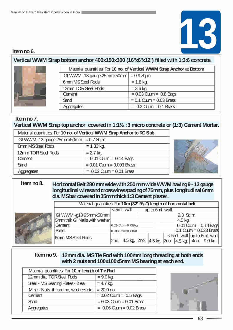
13
Horizontal Belt 280 mm wide with 250 mm wide WWM having 9 - 13 gauge longitudinal wires and cross wires spacing of 75mm, plus longitudinal 6mm dia. MS bar covered in 35mm thick 1:3 Cement plaster.
< 5mt. wall.4.5 kg. 9.0 kg.
1Material quantities: For 10m (32' 9 /2") length of horizontal belt
up to 6mt. wall.6mm MS Steel Rods
Cement Sand
GI WWM -g13 25mmx50mm 2.3 Sq.m5mm thik GI Nails with washer 4.5 kg.
Item no 8.
98
Cement = 0.01 Cu.m = 0.14 Bags
Sand = 0.01 Cu.m = 0.003 Brass
GI WWM -13 gauge 25mmx50mm = 0.7 Sq.m
6mm MS Steel Rods = 1.33 kg.
12mm TOR Steel Rods = 2.7 kg.
Aggregates = 0.02 Cu.m = 0.01 Brass
Material quantities: For 10 no. of Vertical WWM Strap Anchor to RC Slab
Cement = 0.03 Cu.m = 0.8 Bags
Sand = 0.1 Cu.m = 0.03 Brass
GI WWM -13 gauge 25mmx50mm = 0.9 Sq.m
6mm MS Steel Rods = 1.8 kg.
12mm TOR Steel Rods = 3.6 kg.
Aggregates = 0.2 Cu.m = 0.1 Brass
Material quantities: For 10 no. of Vertical WWM Strap Anchor at Bottom
Item no 7.
Item no 6.
Vertical WWM Strap top anchor covered in 1:1½ :3 micro concrete or (1:3) Cement Mortar.
Vertical WWM Strap bottom anchor 400x150x300 (16"x6"x12") filled with 1:3:6 concrete.
13Material quantities: For 10 m length of Tie Rod
Cement = 0.02 Cu.m = 0.5 Bags
Sand = 0.03 Cu.m = 0.01 Brass
12mm dia. TOR Steel Rods = 9.0 kg.
Steel - MS Bearing Plates - 2 ea. = 4.7 kg.
Misc.- Nuts, threading, washers etc. = 20.0 no.
Aggregates = 0.06 Cu.m = 0.02 Brass
Item no 9. 12mm dia. MS Tie Rod with 100mm long threading at both ends with 2 nuts and 100x100x5mm MS bearing at each end.
4no.2no.4.5 kg.2no.4.5 kg.2no.
< 5mt. wall. up to 6mt. wall.
0.01 Cu.m = 0.14 Bags0.024Cu.m=0.73Bag
0.1 Cu.m = 0.033 Brass0.08Cu.m=0.03Brass
Manual on Hazard Resistant Construction in India

Diagonal GI Wire Bracing (X) & Wood Struts for Roof Framing:Struts made of timber planks and bracings made of 4 strands of twisted Pre-tensioned 13gauge GI wires.
4 nails / plank -10gauge 100mm long = 16 no.
100mm (4”) x 25mm (1”) timber plank = 0.03 Cu.m
Material quantities: For 10 Sq.m of Floor/ Roof area
Item no. 13
Material quantities: For 10 Sq.m of Roof area
13 gauge GI Wire = 1.0 Kg
100mm (4”) x 25mm (1”) strut (plank) = 0.2 Cu.m= 8 no.10 gauge Nails100mm long
Item no.14.
99
Brick Column jacketing shear connector 8mm TOR dowel 150mm long, embedded 150mm (6") deep in brick masonry and grouted with appropriate non-shrink grout (1)Non-shrink. Cement : (1) Water.
Timber Attic floor anchor to wall made of 50x50x3mm L shape MS Angle with 300mm(12") long each leg mounted on wall with 4 - 12mm dia. bolts and connected to floor joist with 3-12mm dia. Bolts.
6mm MS Steel Rods = 12.25 kg.
1Material quantities: For 10m (32' 9 /2") height of Column
12mm TOR Steel Rods (Main bars) = 31.6 kg.
Cement = 0.04 Cu.m = 1.25 BagsSand = 0.17 Cu.m = 0.06 Brass
Material quantities: For 10 no.Brick Column Shear Connector.
Steel - 8mm TOR = 1.2kg.Non - shrink Cement =0.4kg.
10"Long 12 mm dia. Bolt with 2 no. Washers & 1 no. nut. 30 no.
8"Long 8 mm dia. Mechanical Fasteners with 1 no. washers & 1 no. nut. 40 no.
Anchor Brackets - MS Angle 50x50x3mm, 12"x12" with three 13mm holes in each leg. 13.80 Kg.
Material quantity: For 10 no. of Anchors
Item no 10.
Item no 11.
Item no 12.
Jacketing of 350x350mm (14"x14") brick column with 8 - 8mm TOR rods and 6mm stirrups at 300 c/c covered in 1:4 Cement mortar.13
Wooden Diagonal Bracing (K) & Struts For Floor and Roof Framing .
Manual on Hazard Resistant Construction in India

’s-
Re
sto
ra
ti
&R
etro
itti
Do
on
f
ng
14While doing Restoration & Retrofitting pay attention to following principles of good practice:
Belt & Vertical Reinforcement
1. Study the building and the levels of door and window lintels to decide the exact alignment of full belt before starting its installation to avoid unexpected obstructions later.
2. Use tube level to mark out the belt alignment and use electric grinder to make a groove along the top and bottom of belt alignment in order to minimize damage to plaster during its removal and thus reduce the cost.
3. Rake all joints 15mm (5/8”) deep and clean the wall surface with wire brush and then with water to ensure good bond with the wall.
4. Ensure total encasing of WWM and bars in cement mortar by keeping a 12mm (½”) gap between wall and WWM with the use of some spacers such that the mortar covers it from behind.
6. End of WWM belt must always overlap with other WWM belt or a steel rod for continuity.
5. Use galvanized WWM for all applications on exterior face of wall to prevent corrosion.
100
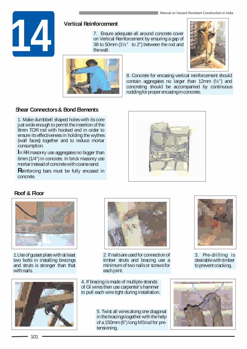
14
Shear Connectors & Bond Elements
1. Make dumbbell shaped holes with its core just wide enough to permit the insertion of the 8mm TOR rod with hooked end in order to ensure its effectiveness in holding the wythes (wall faces) together and to reduce mortar consumption.
In RR masonry use aggregates no bigger than 6mm (1/4”) in concrete. In brick masonry use mortar instead of concrete with coarse sand.
Reinforcing bars must be fully encased in concrete.
Roof & Floor
1.Use of gusset plate with at least two bolts in installing brecings and struts is stronger than that with nails.
2. If nails are used for connection of timber struts and bracing use a minimum of two nails or screws for each joint.
5. Twist all wires along one diagonal in the bracings together with the help of a 150mm (6”) long MS rod for pre-tensioning.
3. Pre-drilling is desirable with timber to prevent cracking.
4. If bracing is made of multiple strands of GI wires then use carpenter's hammer to pull each wire tight during installation.
7. Ensure adequate all around concrete cover on Vertical Reinforcement by ensuring a gap of 38 to 50mm (1½” to 2”) between the rod and the wall.
8. Concrete for encasing vertical reinforcement should contain aggregates no larger than 12mm (½”) and concreting should be accompanied by continuous rodding for proper encasing in concrete.
Vertical Reinforcement
101
Manual on Hazard Resistant Construction in India

15
For Wall Preparation & Making Holes
Power drill with long extension cord
Drill bits of 12mm (1/2"), 16mm (5/8"), 20mm (5/6"), 300mm (12") long.
Electric grinder for plaster cutting
Brick masonry hole making 1tool 35mm (1 /4”) dia. GI pipe
300mm 12” and 450mm 18” long
Wire brush to clean the wall
Tool for raking mortar joints
Safety goggles.
Stone extraction tools
For Shear Anchors and Concreting
Stone extraction rod
Bar bending set
Bar bending tools
Hammer
tongs to hold chisel
Different size chisels for cutting steel rods, WWM and concrete
Pliers with wire cutter
Spanners for the wall anchor bolts
Sheet metal for form work of corner vertical reinforcement concreting
Restoration and Retrofitting involve a few activities that are not carried out in routine construction. These activities require special tools that are not commonly found at a construction site. The list presented below consists mainly of such tools that ought to be procured and kept readily available at site prior to taking up restoration and retrofitting activities. The power tools are optional. But if electric power is available then these tools can not only help in doing a neat job but also greatly expedite the work.
5 kg. Sludge hammer
Having a right tool on hand for each restoration and retrofitting activity is important. It will reduce the effort, increase speed and improve the quality of work.
Tu
o
ols
an
d E
qip
me
nt
Fo
r
en
e
oi
Rtro
fitti
g &
Rs
tra
to
n
102

For WWM Belt
Belt Alignment Marking tools
Cotton String
Tube level
Plumb bob
Heavy duty wire cutter
Binding Wire tightening tool
50x25mm (2"x1") wood batten for forming the lower edge of belt plaster, or an aluminum straight edge 1.82m (6' 0'') long.
Simple Grouting Equipment
Additive measuring cups
Grout pouring mug
Grouting Canister
Carpenter’s saw
Hand drill
Carpenter's hammer
Carpenter's Tools
Grouting Hand pump
Trowel
15
103
Hand drill
Sieve
Bolts & Nails
Big Funnel Small Funnel
Manual on Hazard Resistant Construction in India
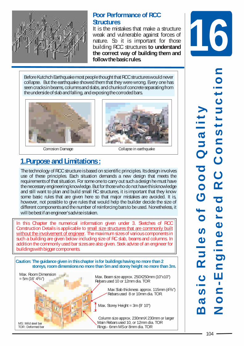
al
sf
du
tB
sic
Ru
e o
Go
o Q
ali
y
No
ie
ds
cn
-En
gn
ere
RC
Co
ntru
tio
n
16
Max. Beam size approx. 250X250mm (10"x10")Rebars used 10 or 12mm dia. TOR
3Max Slab thickness approx. 115mm (4 /8")Rebars used 8 or 10mm dia. TOR.
Column size approx. 230mmX 230mm or largerMain Rebars used 10, or 12mm dia. TORRings - 6mm MS or 8mm dia. TOR
Max. Room Dimension 3= 5m (16' 4 /4")
Max. Storey Height = 3m (9' 10")
Corrosion Damage Collapse in earthquake
Poor Performance of RCC StructuresIt is the mistakes that make a structure weak and vulnerable against forces of nature. So it is important for those building RCC structures to understand the correct way of building them and follow the basic rules.
Before Kutchch Earthquake most people thought that RCC structures would never collapse. But the earthquake showed them that they were wrong. Every one has seen cracks in beams, columns and slabs, and chunks of concrete separating from the underside of slab and falling, and exposing the corroded bars.
The technology of RCC structure is based on scientific principles. Its design involves use of these principles. Each situation demands a new design that meets the requirements of that situation. For some one to carry out such a design he must have the necessary engineering knowledge. But for those who do not have this knowledge and still want to plan and build small RC structures, it is important that they know some basic rules that are given here so that major mistakes are avoided. It is, however, not possible to give rules that would help the builder decide the size of different components and the number of reinforcing bars to be used. Nonetheless, it will be best if an engineer’s advise is taken.
In this Chapter the numerical information given under 3. Sketches of RCC Construction Details is applicable to small size structures that are commonly built without the involvement of engineer. The maximum sizes of various components in such a building are given below including size of RC slab, beams and columns. In addition the commonly used bar sizes are also given. Seek advise of an engineer for buildings with bigger components.
1.Purpose and Limitations :
MS : Mild steel barTOR : Deformed bar
104
Caution: The guidance given in this chapter is for buildings having no more than 2 storeys, room dimensions no more than 5m and storey height no more than 3m.
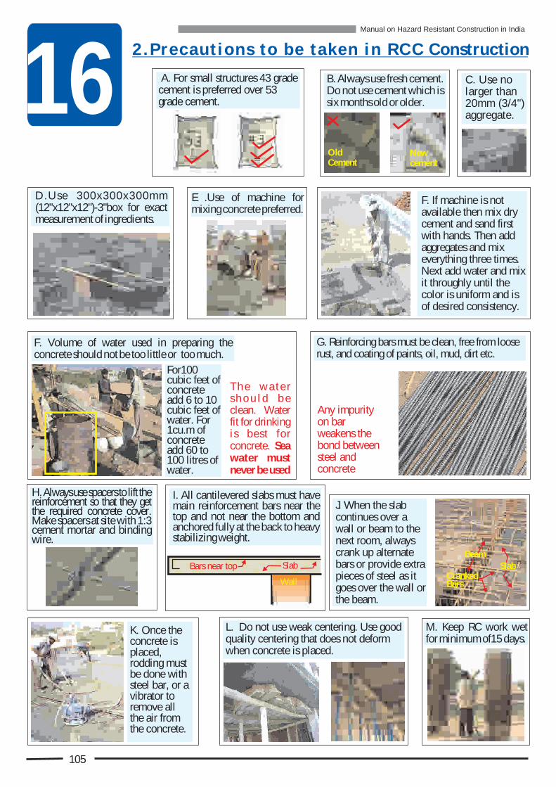
16 A. For small structures 43 grade cement is preferred over 53 grade cement.
C. Use no larger than 20mm (3/4") aggregate.
E .Use of machine for mixing concrete preferred.
F. If machine is not available then mix dry cement and sand first with hands. Then add aggregates and mix everything three times. Next add water and mix it throughly until the color is uniform and is of desired consistency.
D.Use 300x300x300mm (12"x12"x12")-3"box for exact measurement of ingredients.
F. Volume of water used in preparing the concrete should not be too little or too much.
2 . P r e c a u t i o n s t o b e t a k e n i n R C C Construction
G. Reinforcing bars must be clean, free from loose rust, and coating of paints, oil, mud, dirt etc.
H. Always use spacers to lift the reinforcement so that they get the required concrete cover. Make spacers at site with 1:3 cement mortar and binding wire.
J. When the slab continues over a wall or beam to the next room, always crank up alternate bars or provide extra pieces of steel as it goes over the wall or the beam.
M. Keep RC work wet for minimum of15 days.
L. Do not use weak centering. Use good quality centering that does not deform when concrete is placed.
K. Once the concrete is placed, rodding must be done with steel bar, or a vibrator to remove all the air from the concrete.
B. Always use fresh cement. Do not use cement which is six months old or older.
OldCement
Newcement
Bars near top
Wall
SlabBeam
Cranked Bars
Slab
T h e w a t e r s h o u l d b e clean. Water fit for drinking is best for concrete. Sea water must never be used
Any impurity on bar weakens the bond between steel and concrete
For100 cubic feet of concrete add 6 to 10 cubic feet of water. For 1cu.m of concrete add 60 to 100 litres of water.
I. All cantilevered slabs must have main reinforcement bars near the top and not near the bottom and anchored fully at the back to heavy stabilizing weight.
105
Manual on Hazard Resistant Construction in India
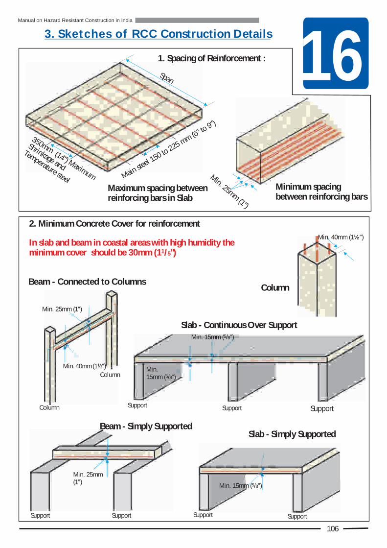
163. S k e t c h e s o f R C C Construction Details
1. Spacing of Reinforcement :
Minimum spacing between reinforcing bars
Maximum spacing between reinforcing bars in Slab
n
Shrinka e d
ga
Temperature steel
Span
106
ain sel
0
6
M
te15
to 225 mm (
" to 9")
m
350mm (14") Maximu M. 25
(
in mm 1")
2. Minimum Concrete Cover for reinforcement
Min. 40mm (1½”)
Slab - Continuous Over Support
Min. 20mm
Beam - Simply Supported Slab - Simply Supported
SupportSupport
SupportSupport Support
Min. 25mm (1”)
Min. 40mm (1½”)
Min. 25mm (1”)
Beam - Connected to Columns
SupportSupport
Column
Column
Min. 20mm
Column
In slab and beam in coastal areas with high humidity the 1minimum cover should be 30mm (1 /5")
5Min. 15mm ( /8”)
Min. 515mm ( /8”)
5Min. 15mm ( /8”)
Manual on Hazard Resistant Construction in India

16
5.Anchorage of Bars: Minimum requirement
Cantilever Beam
Column
Bar of Diameter d1
Bar of Diameter d2L1
L2
L2 = d2 x 50
L1= d1 x 50Simply Supported Beam
Face of Support
Wall
Min.L=50x Bar dia./3
If straight length is not enough then bar can be bent
SupportC
SupportC
50DMin.
50D Min.
Beam Over More Than Two Supports
No splice within beam column joint
No splice
No splice
No splice
Splice OK
L
2d 2d0.25L 0.25LNo splice
Splice OK
Anchorage for bar from next span
In a beam Lap splices must have ties
50xbar dia.
Ties at spacing no more than 150mm (6") apart
L
dBar dia. D
107
Max. 50mm (2”)
Ties/Rings at Max. d/2
TOR bar dia. D1
2d
Beam
Min. 2 bars throughout at top & bottom
Column
Ties/ Rings at: Lesser of d/4 or 8D2
But 100mm
4. Suggested Tie/Ring Spacings for Beams
2d
d
Bar dia. D2
5D
1M
n.0
i
D2
Mn.
50
i
<I
Column
Bend alternate
Column
Bottom Bar
L/5 L/3
L/5L/7L L
Separate bar - top steel
L/5
L/3
Two straight bars from one end to the other
Column
Manual on Hazard Resistant Construction in India
3. Reinforcement Arrangement in Continuous Beam
At least two straight bars must be provided at top and at bottom in the entire length of the beam in addition to the bars shown here.
(Equal or nearly equal spans and uniformly loaded)

16
Beam Bars should run straight through column
Beam Bars
BeamColumnBeam Bars
9. Beam Column Joint
8. Tie for Column Size less than 300mm
5mm7 )(3"
Column
d8 TOR ia.Tie
Column
T ei
Beam
Beam
Column
30
9
0")
00m
('1
060
mm
(")
2400
mm
6(
42")
100
mm
8'
1)
(51
"
Lap vertical bars in middle half only
mm
ties
@ 1
50 (6
")60
mm
(24
)0
"Ti
e @
75
s-
10m
m0
(3"
-4"
)
60m
(4"
0m
2)
Tes
5-i
@7
00m
1
m3"
- 4
)(
"
Provide ties @ 75-100mm within the joint. Also see 9.
6. Confining Reinforcement in
500m
mTi
es @
75-
100m
m (3
”-4”
) a
art
p
500m
m(
)20
"ie
-
Ts
@75
m
100
m(
-"
3"4
)
Bend alternate
Suppor SupporSuppor L1 L2 L2
L /32
L /52 L /52
CSuppor
a a ab
c
b
c = bottom steel ; a = alternate bent bars(from c); b = extra straight bars if needed
10.Continuous Slab Suggested bar arrangement (Simply supported at ends and intermediate supports)
L /31 L /31
L /71 L /51
c
7. Special Confining Reinforcement in Column Ending in Footing
Tie Spacing 75-100mm (3”-4”)
300mm (12”)
Footing
Column
Caution: Ties must extend in to footing
600mm (24”)
11. Simply Supported Slab & Beam Reinforcement Arrangement
Temperature Steel
Alternate bar of main steel bent up
L/7
20
50D/3
20 Main Steel
Bar dia. D
L
108
Manual on Hazard Resistant Construction in India

1. A.S.Arya Dr. Principal Seismic Advisor, NDMA, Ministry of Home Affairs, Government of India, 2005, Guidelines for “Repair, Restoration and Retrofitting of Masonry Buildings in Earthquake Affected Areas of Jammu & Kashmir”. and Guidelines for “Earthquake Resistant Reconstruction and New Construction of Masonry Buildings in Jammu and Kashmir State”
2. A.S.Arya Dr., Gujarat State Disaster Management Authority, Government of Gujarat. 2002, Guidelines for “Repair, Restoration and Retrofitting of Masonry Buildings in Kutchch Earthquake Affected Areas of Gujarat” and Guidelines for “Reconstruction and New Construction of Houses in Kutchch Earthquake Affected Areas of Gujarat”.
3. Anand S. Arya Dr., 2007, “Earthquake Disaster Reduction: Masonry Buildings, Design and Construction”
4. BMTPC, 2000, “Guidelines for Damage Assessment and Post-Earthquake Action Part” II: “Repair and Retrofitting of Buildings in the Chomoli Earthquake Affected Areas”,
5. BMTPC, 1999, “Guidelines Improving Earthquake Resistance of Housing”, 6. BMPTC, Government of India, “Guide to Earthquake Safety for Uttaranchal” 7. BMTPC, 1997, Vulnerability Atlas of India8. BMTPC, 1999-2000, “Guidelines Improving Wind/Cyclone Resistance of Housing9. BMTPC, 2000, “Manual on Earthquake Safety for Garhwal” in Hindi language10. DESAI, RAJENDRA, 1999, “Field Shake Table Program - A Sure Way of Confidence
Building in Quake Resistant Building Technology”, ASAG, (unpublished, available from the author)
11. ASAG,, 1994, “Earthquake and our House” in Marathi Language12. ASAG, 1994, “Repaires and Retrofitting The Marathwada Houses”13. NCPDP, 2006, “Manual for restoration and Retrofitting of Rural Vernacular
Structures in Kashmir”. 14. SCRC-UNDP, 1996, “Guidelines for Mitigating Damage to Dwellings due to
Cyclones”15. BRE 1988 “Cyclone-Resistant Houses for Developing Countries”16. HUDCO, 2000 “Guidelines for Building Reconstruction in Cyclone Affected Areas
in Orissa”17. .Indian Society of Earthquake Technology, Roorkee, 1989, “A Manual of Earthquake
Resistant Non-Engineered Construction”18. “Improving Earthquake Resistance of Low Strength Masonry Buildings-Guidelines”,
IS:13828:199319. “Improving Earthquake Resistance of Earthen Buildings-Guidelines”, IS:13827:199320. “Repair & Seismic Strengthening of Buildings-Guidelines”, IS:13935:1993.21. “Earthquake Resistant Design and Construction of Buildings Code of Practice”
(Second Revision), IS:4326-199322. “Plain and reinforce concrete” IS 456:20023. Ductile Detailing of Reinforced Concrete Structures subjected to Seismic Forces -
Code of Practice” IS 13920-1993
REFERENCES
A
109
Manual on Hazard Resistant Construction in India

National Centre for Peoples'-Action in Disaster Preparedness (NCPDP)NCPDP was created with a focus on disaster preparedness in October, 2000 at the time of Bhavnagar Earthquake in Gujarat. This was an outcome of seven years of post earthquake intervention by its two honorary directors in regions of Latur, Jabalpur and Chomoli in India. Later, it played a major role in rehabilitation as well as capacity building for long-term preparedness in Gujarat in the aftermath of Kutchch Earthquake, and also worked on capacity building and technology demonstration in the quake affected Kashmir.
NCPDP is one of a few technology-based organizations in the country with first-hand experience of working at the grass-roots. It has a firm belief that building capacity of people from within is the only way to mitigate disasters for a safer world. Hence, we believe that intervention by external agencies in the aftermath of a disaster is most needed to work in this direction. Skill up-gradation of building artisans should form the backbone of this approach.
NCPDP strives to bring viable, eco-friendly and sustainable technologies to help people reduce their vulnerability against future disasters. It strives to remain prepared for timely intervention in the aftermath of major disasters. It is continuing to work on disaster mitigation through (a) training of engineers and building artisans, (b) awareness & confidence building programs in communities, (c) preparing ready to use technical information for people, (d) research on structural behavior of masonry structures, and (e) building vulnerability studies in different parts of India. (f).vulnerability reduction through retrofitting (g). policy interventions.
About GOI-UNDP DRM Programme
About NCPDP
Disaster Risk Management Programme is a multi donor funded, joint GOI-UNDP Programme being implemented in 169 multi hazard prone districts of 17 selected states, with the overall goal of sustainable reduction in disaster risk across India.
The main objectives of the programme are as follows:
• National Capacity Building to institutionalize the system for natural disaster risk management in the Ministry Of Home Affairs
• Environment building, education, awareness programmes and strengthening capacities at all levels in disaster risk management and sustainable recovery
• Multi hazard preparedness, response and mitigation plans for disaster risk management, developing and promoting policy frameworks at state and national level.
Urban Earthquake Vulnerability Reduction Project, a sub component of the GOI-UNDP DRM Programme is being implemented in 38 seismic prone cities of India falling either in Zone III, IV and V having a population of more than half a million. The project aims at sustainable reduction in earthquake risk in urban areas of India.
The major objectives of the project are• Creating awareness on earthquake preparedness.• Building up the capacity of professionals like architects, engineers and masons on earthquake resistant
construction technology.• Amending the building rules /Byelwas to ensure to structural safety in natural hazard prone areas.• Build the capacity of local community by putting in place earthquake preparedness and response plan
and training them in life supporting skills for effective response in a post disaster situation.• Networking of knowledge and best practices across the cities on earthquake risk preparedness and
mitigation.

For more information
National Disaster Management Division
Ministry of Home Affairs
Government of India
www.ndmindia.nic.in