manual of septic tank practice
TRANSCRIPT

PB21624011111111111111111111111111111111111111111111111111
)tOHIlOI o{
SEPTIC - TANKPRACTICE
••••••••••••••••••••••••••••••••••••••••••
::J)eve/cfel in Coofetalicu witk lite
joinl Committee on I'<utal c£anitalion•••••••••••••••••••••••••••••
Co tU"'l,.
~~~~~'t{~;.· .~-m.~t. <.,. c.ii~.~,. ......Ai') 6' .,? e~~ .,.
,. 17-9_.~·_-,-:R=EP=RO=-OU=C~ED-;:;CBYC::-
NA1iONAl TECHNiCALINfORMAliON SERVICE
u. S. DEPARTMENT OF COMMERCESPRINGFIELD, VA. 22161
U.S. DEPA.i:TMENT OF HEALTH, EDUCATION, AND WELFARE(:iJi PUBLIC HEALTH SERVICE
Bureau of Disease Prevenlion and Environmental ControlNalional Center ror Urban and Induslrial Health
, Cincinnali, Ohio 45202
••••••••••••••

4Public Health Service Publication No. 526
Firs t Printed 1957
Reprinted 1~63
Revi~~~~J~ .

PB-216 240
Report Nos: PHS~PUB-526-REV
Title: Manual of Septic-Tank Practice. Revised Edition.
Date: 1967
Performing Organization: National Center for Urban and Industrial Health,Cincinnati, Ohio.
Supplemental Notes: Prepared in cooperation with 'the Joint Committee onRural Sanitation.1967 Revision of report dated 1957 and reprinted 1963.
NTIS Field/Group Codes: 68D (Water Pollution & Control)
Price: PC A07/MF A02
Availability: Order this product from NTIS by: phone at 1-800-553-NTIS(U.S. customers); (703)605-6000 (other countries); fax at (703)605-6900;and email at [email protected]. NTIS is located at 5285 Port RoyalRoad, Springfield, VA, 22161, USA.
Number of Pages:" 102p
Keywords: *Septic tanks, Reviews, Design, Handbooks.
Abstract: Contents: Septic tank - soil absorption systems for privateresidences; Septic tank,- soil absorption systems for institutions,recreational areas, and other establishments.


~ - .----.-
It is particularly important that proper safety precautionsbe taken when percolation holes or larger excavations aredug to install septic tanks or seepage pits. Means shouldbe provided to prevent the side~walls from collapsing whileworkmen are in the hole. A common method of affording properprotection to the workmen is through the use of sheeting formed
-by semicircular sections of corrugated metal, braced withsemicircular compression rods which are bolted on the insidewith expansion bolts. In another type of seepage pit construction, the walls are made of precast rein£orced concrete sectionswith slotted holes. For deep seepage pits, or where thereis any danger of caving, the sections are installed as theexcavation progresses, and are used as the necessary protectivesheeting. Dur.ing non-work periods holes should be covered withboards that cannot be easily removed or the hole should besurrounded with a fence that cannot be easily entered. Anyopen hole is dangerous and should be filled in when the workis completed. Fatal accidents have occured when these basicsafety measures have not been observed.
.' .il

.'.
·n
-!\c.
Foreword
In the preparation of this manual, the Public Health Service wasfortunate in having the advisory assistance of the Joint Committee onRural Sanitation. This committee is composed of specialists from governmental and other agencies in the field of rural sanitation. Theircomments and suggestions based on the long experience of the members were invaluable in the preparation of the manual. The followingindividuals and organizations .constitute the current Committeemembership:U.S. DEPARTMENT OF AGRICULTURE:
Agricultural Research ServiceHarry J. Eby, Agricultural Engineer, Agricultural EngineeringResearch Branch.
Farmers' Home AdministrationEarl :R. Bell, Agricultural Engineer.
Federal Extension Service1" W. T. Cox, Agricultural Engineer.
Forest ServiceH. A. Smallwood, Division of Engineering, Consultation, andStandards.
Soil Conservation ServiceWilliam G. Shannon, Chief, Water Supply Forecasting Branch,Engineering Division.
AMERICAN PUBLIC HEALTH .ASSOCIATION:
Professor John E. Kiker, Jr., College of Engineering, University ofFlorida.
U.S. COAST GUARD:
Captain James H. Le Van, Chief Sanitary Engineer Officer.CONFERENCE OF MUNICIPAL PUBLIC HEALTH ENGINEERS:
William H. Cary, Jr., Associate Director for Environmental Health,D.C. Department of Public Health.
FEDERAL HOUSING ADMINISTRATION:
William K. Rodman, Special Assistant for the Technical StudiesProgram.
FEDERATION OF SEWAGE AND INDUSTRIAL WASTES ASSOCIATIONS:
David B. Lee, Director, Bureau of Sanitary Engineering, FloridaState Board of Health.
iii

U.S. DEPARTMENT OF HEALTH, EDUCATION, AND WELFARE:
Office of EducationJohn L. Cameron, Acting Director, Division oE Facilities Development.
Public Health Service ?
Malcolm C. Hope, sanitary Engineer Director.Joseph P. Schock, Public Health Engineer.
U.S. DEPARTMENT OF THE INTERIOR:
U.S. Geological SurveyClyde S. Conover, District Chief, Water Resources Division.
TENNESSEE VALLEY AUTHORITY:
F. E. Gartrell, Assistant Director oE Health.VETERANS HOUSING ADMINISTRATION:
D. J. Guthridge, Construction and Valuation Specialist.INDUSTRY ADVISORS:
John G. Hendrickson, Jr., Portland Cement Association.James J. Spear, Spear Water and Sewerage Supplies
iv

Preface
Population movement within the United States continues to be fromrural to metropolitan areas. Because of the difficulty of providing adequate sewerage systems for this new growth, individual septic tank - soilabsorption systems continue to be an important method of sewagedisposal where they are acceptable. Accurate figures are not available,but it is estimated that at present 49 million persons are served by 15million individual sewage-disposal systems in the United States. Of evenmore importance, roughly one-fourth of the new homes are being constructed with these systems.
In 1946, the Public Health Service, in cooperation with Federalagencies concerned with housing, undertook a 5-year study on septictank - soil absorption systems, seeking to develop a factual basis on whichthey could be designed, installed and maintained. These studies aredescribed in detail in three technical reports: Studies on HouseholdSewage Disposal Systems, Parts I, II, and III.
Subsequent studies on septic tanks and soil absorption systems havebeen conducted by the Public Health Service, Federal Housing Administration, Universities and other organizations.
This manual is a revision of PHS Publication No. 526, Manual ofSeptic Tank Practice, issued in 1957, and reprinted in 1963 withAddendums on "Serial Distribution Systems" and "Seepage Beds," Theupdating reflects changing trends in the problems of individual sewagedisposal systems and includes new information in this field.
The decision on the suitability of septic-tank installations must bebased on many factors outside of those covered in the manual. It isemphasized, however, that connection to an adequate public seweragesystem is the most satisfactory method of disposing of sewage. Everyeffort should be made, therefore, to secure public-sewer extensions.Where connection to a public sewer is not feasible, and when a considerable number of residences are to be served, consideration shouldbe given next to the construction of a community sewerage system andtreatment plant. Specific information on this matter should be obtainedfrom the local authority having jurisdiction.
Individuals proposing to construct individual sewage-disposal systemsshould consult the officials having jurisdiction over such installations intheir area. A number of States and localities have developed requirements which have been incorporated in their official regulations, inmany cases soundly based on conditions peculiar to those areas and
v

adequately representing good practice there. The recommendationscontained in this manual should be considered as supplemental to suchlocal requirements. Builders, homeowners, and others interested inseptic-tank systems should seek advance guidance from the local authorities prior to land acquisition, in order to have the benefits of theirexperience as well as their approval of plans and construction.
vi

48
10121415161617172020232626262727272729292929303030323334
~
PART I~-SEPTIC T~NK - SOIL ABSORPTION/~hSTEMSFOR/PRIVATE K'ESIDENCES '-- ," , /. ~ - ..'\- ~~ I
Introduction 1Definitions 2 'j
Suitability of Soil 3 dr" -(Percolation Tests .. .. .. . 4
Procedure for Percolation Tests Developed at Robert A.Taft Sanitary Engineering Center
Soil Absorption SystemAbsorption Trenches
Cons truction Considera tionsSeepage Beds . . . .. .
Construction ConsiderationsDistribution BoxesSerial Distribution
Fields in Flat AreasFields in Sloping Ground .
Deep Absorption Trenches and Seepage BedsSeepage Pi ts
Sample CalculationsConstruction Considerations
Selection of a Septic Tank .Functions of Septic Tanks
Removal of SolidsBiological TreatmentSludge and Scum StorageLocationEffluentCapacity
Specifications for Septic TanksMaterialsGeneralInletOutletTank Pr<;>portions ...Storage Above Liquid Level .Use of Compartments
vii
(.. -{'.j -"
c/' "/
General Information on/ Cleaning.
/ Grease In terceptorsI· Chemicals ..
MiscellaneousInspection
Septic Tanks. 353538383839
"PART II~'<;SEPTJC TANK - S6IL A'BSORPTION SYSTEMS IFOR INSTITUTIONS,
:;. I' / > r ~
REdREATJONAL ~EAS, AND 0THER/EsTABLISHMENTS/ I
Introduction ... .I 41Estimates of Sewage Quantities 42Estimates of Soil Absorption Areas . 45Building Sewers 48Collection Systems 49~e~Tn~ 50
Location 50Construction Details 51Capacity 52Operation 53
Septic Tanks for Institutional Systems 53Capacities 54
Dosing Tanks .. 55Sand-Filter Trenches 56
Construction Features 60Subsurface Sand Filters 62
Construction Features 62Superficial Sand Filters 64Chlorination .... . 66
ApPENDICES
Introduction to AppendicesA. Soil Absorption Capacity
Guide for Estimating Soil Absorption PotentialSoil MapsClues to Absorption CapacityTexture .StructureColorDepth or Thickness of Permeable StrataSwelling Characteristics
.Evapotranspira tionCurtain Drains for Absorption Trench Systems
viii
717272727272737373737474

Percolation Test Holes 75Other Percolation Tests """ "" " "" .. "" " .. " ""...... 75
B. Suggested Ordinance 77C. Engineering Information Forms 81D. Drainage Fixture Unit Values 85E. Suggested Specifications for Watertight Concrete. 86F. Industrial Waste Treatment 88BIBLIOGRAPHY 91
ix

\

Part I
Septic Tank - Soil Absorption
Systems for Private Residences
INTRODUCTIONA major factor influencing the health of individuals where public
sewers are not available is the proper disposal of human excreta. Manydiseases, such as dysentery, infectious hepatitis, typhoid and paratyphoid, and various types of diarrhea (Ire transmitted from one personto another through the fecal contamination of food and water, largelydue to the improper disposal of human wastes. For this reason, everyeffort should be made to prevent such hazards and to dispose of allhuman waste so that no opportunity will exist for contamination ofwater or food.
Safe disposal of all human and domestic wastes is necessary to protectthe health of the individual family and the community and to preventthe occurrence of nuisances. To accomplish satisfactory results, suchwastes must be disposed of so that:
1. They will not contaminate any drinking water supply.2. They will not give rise to a public health hazard by being acces
sible to insects, rodents, or othel' possible carriers which may come intocontact with food or drinking ,water.
3. They will not give rise to a public health hazard by beingaccessible to children.
4. They will not violate laws or regulations governing water pollution or sewage disposal.
5. They will not pollute or contaminate the waters of any bathingbeach, shellfish breeding ground, or stream used for public or domesticwater supply purposes, or for recreational purposes.
6. They will not give rise to a nuisance due to odor or unsightlyappearance.
These criteria can best be met by the discharge of domestic sewageto an adequate public or community sewerage system. vVhere the instal-

!ation of an individual household sewage disposal system is necessary,the basic principles outlined in this manual on design, construction,installation, and maintenance should be followed. ""\Then these criteriaare met, and where soil and site conditions are favorable, the septictank system can be expected to give satisfactory service. Experience hasshown that adequate supervision, inspection and maintenance ofall features of the system are required to insure compliance in thisrespect. Underground portions of the system should be inspected beforebeing covered, so necessary corrections can be made.
DEFINITIONS
Absorption Trench-A trench not over 36" in width with a minimumof 12" of clean, coarse aggregate and a distribution pipe, and coveredwith a minimum of 12" of earth cover.
Standard Absorption Trench-A trench 12" to 36" in width containing 12" of clean, coarse aggregate and a distribution pipe, coveredwith a minimum- of 12" of earth cover.
Building Drain-That part of the lowest piping of a drainage systemwhich receives the discharge from soil, waste, and other drainage pipesinside the walls of the building and conveys it to the building sewerbeginning three feet outside the building wall.
Building SetiJer-That part of a drainage system which extends fromthe end of the building drain and conveys its discharge to a publicsewer, private sewer, individual sewage disposal system or other pointof disposal.
Cesspool-A lined and covered excavation in the ground which reoceives the discharge of domestic sewage or other organic wastes from adrainage system, so designed as to retain the organic matter and solids,but permitting the liquids to seep through the bottom and sides.
Drainage Fixture Unit Value-A common measure of the probabledischarge into a drainage system by various types of plumbing fixtures.This value for a particular fixture depends on its volume rate of drainage discharge, on the time duration of a single drainage operation, andon the average time between successive operations.
Effective Size-That size of sand of which 10% by weight is smaller.Individual Sewage Disposal System-A singl~ system of sewage treat
ment tanks and disposal facilities serving only a single lot.Sand Filter Trenches-A system of trenches, consisting of perforated
pipe or drain tile surrounded by clean, coarse aggregate containing anintermediate layer of sand as filtering material and provided with anunderdrain for carrying off the filtered sewage.
Scum-A mass of sewage matter which floats on the surface of sewage.Scum Clear Space-Distance between the bottom of the scum mat
and the bottom of the outlet device.Seepage Bed-A trench or bed exceeding 36" in width containing 12"
2

a minimum of clean, coarse aggregate and a system of distribution piping through which treated sewage may seep into the surrounding soil.
Seepage Pit-A covered pit with lining designed to permit treatedsewage to seep into the surrounding soil.
Septic Tank-A water-tight, covered receptacle designed and con·structed to receive the discharge of sewage from a building sewer, separate solids from the liquid, digest organic matter and store digestedsolids through a period of detention, and allow the clarified liquids todischarge for final disposal.
Serial Distribution-An arrangement of absorption trenches, seepagepits, or seepage beds so that each is forced to pond to utilize the totaleffective absorption area before liquid flows into the succeedingcomponent.
Sewage-Any liquid waste containing animal or vegetable matter insuspension or solution, and may include liquids containing chemicalsin solution.
Sludge-The accumulated settled solids deposited from sewage andcontaining more or less water to form a semi-liquid mass.
Sludge Clear Space-The distance between the top of the sludge andthe bottom of the outletdevice.
Soil Absorption Field-A system of absorption trenches.Soil Absorption System-Any system that utilizes the soil for subse
quent absorption of the treated sewage; such as an absorption trench,I
seepage bed, or a seepage pit.Subsurface Sand Filters-A wide bed, consisting of a number of lines
of perforated pipe or drain tile surrounded by clean coarse aggregate,containing an in termediate layer of sand as filtering material, andprovided with a system of underdrains for carrying off the filteredsewage.
Subsurface Sewage Disposal System-A system for the treatment anddisposal of domestic sewage by means of a septic tank and a soil absorption system.
Uniformity Coefficient-A coefficient obtained by dividing that sizeof sand of which 60% by weight is smaller, by that size of sand ofwhich 10% by weight is .smaller.
SUITABILITY OF SOIL
The first step in the design of subsurface sewage disposal systems isto determine whether the soil is suitable for the absorption of septictank effluent and, if so, how much area is required. The soil must havean acceptable percolation rate, without interference from ground wateror impervious strata below the level of the absorption system. In general, two conditions must be met:
(1) The percolation time should be within the range of those specified in Table 1, p. 8.
3

(2) The maximum seasonal elevation of the grcund water tableshould be at least 4-feet below the bottom of the trench or seepagepit. Rock formulations or other impervious strata should be at a depthgreater than 4-feet below the bottom of trench or seepage pit.
Unless these conditions can be satisfied, the site is unsuitable for aconventional subsurface sewage disposal system.
PERCOLATION TESTS
Subsurface explorations are necessary to determine subsurface formations in a given area. An auger with an extension handle, as shown inFigure 1 (p. 5), is often used for making the investigation. In somecases, an examination of road cuts, stream embankments, or buildingexcavations will give useful information. Wells and well drillers' logscan also be used to obtain information on ground water and subsurfaceconditions. In some areas, subsoil strata vary widely in short distances,and borings must be made at the site of the system. If the subsoil appears suitable, as judged by other characteristics described in Appendix A, percolation tests should be made at poin ts and elevations selectedas typical of the area in which the disposal. field will be located.
The percolation tests help to determine the acceptability of the siteand establish the design size of the subsurface disposal system. Thelength of time required for percolation tests will vary in different typesof soil. The safest method is to make tests in holes which have beenkept filled with water for at least 4 hours, preferably overnight. Thisis particularly desirable if the tests are to be made by an inexperiencedperson, and in some soils it is necessary even if the individual has hadconsiderable experience (as in soils which swell upon wetting). Percolation rates should be figured on the basis of the test data obtained afterthe soil has had opportunity to become wetted or saturated and hashad opportunity to swell for at least 24 hours. Enough tests should bemade in separate holes to assure that the results. are valid.
The percolation test developed at the Robert A. Taft Sanitary Engineering Center incorporates these principles. Its use is particularlyreco'mmended when knowledge of soil types and soil structure is limited. When previous experience and information on soil characteristicsare available, some persons prefer other percolation test procedures,such as those developed by Kiker and by Ludwig which are cited inAppendix A.
Procedure for Percolation Tests Developed at Robert A. Taft SanitaryEngineering Center
1. Number and location of tests.-Six or more tests shall be made inseparate test holes spaced uniformly over the proposed absorption fieldsite.
2. Type of test hole.-Dig or bore a hole, with horizontal dimensionsof from 4 to 12 inches and vertical sides to the depth of the proposedabsorption trench. In order to save time, labor, and volume of water
4

---~~- =---:..
---_.- ----
~ ;I,"P
"
i ~';'. ~
"~ ~ ... '.1
} ~ I :I t~
jI
11,IIt
;
I
:,
.~.,;
l·
:1
Figure I.-Auger and extension handle for making test borings.
s

required per test, the holes can be bored with a 4 inch auger. (SeeFig. 2, page 7.)
3. Preparation of test hole.-Carefully scratch the bottom and sidesof the hole with a knife blade or sharp-pointed instrument, in orderto remove any smeared soil surfaces and to provide a natural soil interface into which water may percolate. Remove all loose material fromthe hole. Add 2 inches of coarse sand or fine gravel to protect thebottom from scouring and sediment.
4. Saturation and swelli~g of the soil.-It is important to distinguish between saturation and swelling. Saturation means that the voidspaces between soil particles are full of water. This can be accomplishedin a short period of time. Swelling is caused by intrusion of water intothe individual soil particle. This is a slow process, especially in claytype soil, and is the reason for requiring a prolonged soaking period.
In the conduct of the test. carefully fill the hole with clear water toa minimum depth of 12 inches over the gravel. In most soils, it is necessary to refill the hole by supplying a surplus reservoir of water, possiblyby means of an automatic syphon, to keep water in the hole for at least4 hours and preferably overnight. Determine the percolation rate 24hours after water is first added to the hole. This procedure is to insurethat the soil is given ample opportunity to swell and to approach thecondition it will be in during the wettest season of the year. Thus, thetest will give comparable results in the same soil, whether made in adry or in a wet season. In sandy soils containing little or no clay, theswelling procedure is not essential, and the test may be made as described under item 5C, after the water from one filling of the hole has
. completely seeped away.5. Percolation-rate measurement.-VVith the exception of sandy soils,
percolation-rate measurements shall be made on the day following theprocedure described under item 4, above.
A If water remains in the test hole after the overnight swelling period, adjust the depth to approximately 6 inches over the gravel. From'I- fixed reference point, measure the drop in water level over a 30 minute period. This drop is used to calculate the percolation rate.
E. If no water remains in the hole after the overnight swelling period, add clear water to bring the depth of water in the hole to approximately 6 inches over the gravel. From a fixed reference point, measurethe drop in water level at approximately 30 minute intervals for 4hours, refilling 6 inches over the gravel as necessary. The drop thatoccurs during the final 30 minute period is used to calculate the percolation rate. The drops during prior periods provide information forpossible modification of the procedure to suit local circumstances.
C. In sandy soils (or other soils in which the first 6 inches of waterseeps away in less than 30 minutes, after the overnight swelling period),the time interval between measurements shall be taken ~s 10 minutesand the test run for one hour. The drop that occurs during the final10 minutes is used to calculate the percolation rate.
6

r-~.--'---""--"'-;-'--"---"-"""'-~--.-~
: ~ j
""_'".l,_'.±_-_I~ ,.:, c--c....-"'-'--~I2" LAYER OF
GRAVEL
NOTE, LEAVE BAnER BOARD IN PLACE' . ,
BE CAREFUL NOT TO MOVE IT 'l'.'
DURING TEST,
c------_·~ ~ ~
!J4~~rF~~~;;~1:.~,.",1-'~~~:~i/J: WHENMAKiNG PERCOLA~I()N r'·"'·~'· :~~::.t~~J
'TESTS MARK LINES HERE AT I "".c2.REGU_~_R_~I~E_I~!ERVA~ __ .J .
Figure 2.-Methods of making percolation tests.
"=---
7

Table I.-Absorption-area requirements for individual residences (a)
[Provides for garbage grinder and automatic clothes washing machines]
Required absorp- Required absorp-tion area, in tion area in sq. ft.Percolation rate (time sq. ft. per Percolation rate (time per bedroom (b),required for water to bedroom (b), required for water to standard trenchfall one inch, standard trench fall one inch, (c), and seepage
in minutes) (c), seepage beds in minutes) beds (c), and(c), and seepage seepage pits (d)pits (d)
I or less 70 10.. 165
2 85 15. 190
3 100 30 (e) 250
4 .. Il5 45 (e) .. 300
5 ....... 125 60 (e), (f) .. 330
(a) It is desirable to provide sufficient land area for entire new absorption systemif needed in future.'
(b) In every case sufficient land area should be provided for the number of bedrooms (minimum of 2) that can be reasonably anticipated, including the unfinishedspace available for conversion as additional bedrooms.
(c) Absorption area is figured as trench-bottom area and includes a statistical al·lowance for vertical side wall area.
(d) Absorption area for seepage pits is figured as effective side wall area beneaththe inlet.
(e) Unsuitable for seepage pits if over thirty.(f) Unsuitable for absorption systems if over sixty.
'Section 5.1(b) (2) (A) Page 20 of Recommended State Legislation a.nd Regulations:Urban Water Supply and Sewerage Systems Act and Regulations, Water Well Can·struction and Pump Installation Act and Regulations, Individual Sewerage DisposalSystems Act and Regulations. U.S.D.H.E.W., Public Health Service. July 1%5.
SOIL ABSORPTION SYSTEM
For areas where the percolation rates and soil characteristics aregood, the next step after making the percolation tests is to determinethe required absorption area from Table 1 or Figure 3 (page 9), andto select the soil absorption system tha t will be satisfactory for thearea in question. As noted in Table 1, soil in which the percolationrate is slower than 1 inch in 30 minutes is unsuitable for seepage pits,and that slower than 1 inch in 60 minutes is unsuitable for any typeof soil absorption system.
,,--~-~.--~-~' iI
-.....-~~- -----" ~ -~---
8

350
::::IE 30000ao::Cl.....=ao::.....
250CL..
Cl.....ao::::::l01.....ao:: 200.....:.....ao::.....::z0>- 150CL..ao::0VI=.....:.....0
100>-....................ao::.....:::::l
5001VI
./~
/'/
/V
JV
I/
oo 10 20 30 40 50
PERCOLATION RATE IN MINUTES PER INCH
Figure 3.-Absorption area requirements for private residences.
60
When a soil absorption system is determined to be useable, threetypes of design may be considered: Absorption trenches, seepage beds.and seepage pits. A modification of the standard absorption trench isdiscussed on page 20 giving credit for more than the standard 12 inchesof gravel depth in the trench.
The selection of the absorption system will be dependent to someextent on the location of the system in the area under consideration.A safe distance should be maintained between the site and any sourceof water supply. Since the distance that pollution will travel underground depends upon numerous factors, including the characteristicsof the subsoil formations and the quantity of sewage discharged, nospecified distance would be absolutely safe in all localities. Ordiriarily,of course, the greater the distance, the greater will be the safety provided. In general, location of components of sewage disposal systemsshould be as shown in the following table.
9

Table 2.-Minimum distance between components of sewage disposal system
Horizontal Distance (feet)
-Component Well or Water
supply Propertyof suction line Stream Dwelling line
System line (pressure)
Building sewer 50 10 (a) 50 .,,- .,; .Septic tank. 50 10 50 5 10
Disposal field andSeepage Bed.... 100 25 50 20 , 5
Seepage Pit.. 100 50 50 20 10Cesspool (b) . 150 50 50 20 15
(a) Where the water supply'line must cross the sewer line. the bottom of thewater service within 10 feet of the point of crossing, shall be at least 12 inchesabove the top of the sewer line. The sewer line shall· be of cast iron with leaded ormechanical joints at least 10 feet on either side of the crossing.
(b) Not recommended as a substitute for a septic tank. To be used only whenfound necessary and approved by the health authority,
Seepage pits should not be used in areas where domestic water supplies are obtained from shallow wells, or where there are limestoneformations and sinkholes with connection to underground. channelsthrough which pollution may travel to water sources.
Details pertaining to local water wells, such as depth, type of con·struction, vertical zone of influence, etc., together with data on thegeological formations and porOsity of subsoil strata, should be considered in determining the safe allowable distance between wells and subsurface disposal systems.
Absorption Trenches
A soil absorption field consists of a field of 12 inch lengths of 4 inchagricultural drain tile, 2 to 3 foot lengths of vitrified clay sewer pipe,or perforated, nonmetallic pipe. In areas having unusual soil or watercharacteristics, local experience should be reviewed before selectingpiping materials. The individual laterals preferably should not be over100 feet long, and the trench bottom and tile distribution lines shouldbe level. .Use of more and shorter laterals is preferred because if some·thing should happen to disturb one line, most of the field will still beserviceable. From a theoretical mois ture flow yiewpoin t, a spacing oftwice the depth of gravel would prevent taxing the percoLitive capacityof the adjacent soil.
Many different designs may be used in laying out subsurface disposalfields. The choice may depend on the size and shape of the available
10

disposal area: the capacity required, and the topography of the disposalarea.
Typical layouts of absorption trenches are shown in Figures 4, 6,pages 11, and 17.
To provide the minimum required gravel depth and earth cover, thedepth of the absorption trenches should be at least 24 inches. Additional depth may be needed for contour adjustment, extra aggregateunder the tile, or other design purposes. The maintenance of a 4 feetseparation between the bottom of the trench and the water table isrequired to minimize ground water contamination. In considering thedepth of the absorption field trenches, the possibility of tile lines freezing during prolonged cold period is raised. Freezing rarely occurs in acarefully constructed system kept in continuous operation. It is important during construction to assure that the tile lines are surrounded bygravel. Pipes under driveways or other surfaces which are usuallycleared of snow should be insulated.
j)
.. ,:.~.,".""-:""~'~:"''''G4 S,. ::JA';"'P;S~?(• ~I~-=:...=:;.",.;----:;;:;;-'--C:-=-=--=-=-
I /SECTION A-A
~ -.,
=== ,'.DASHED LINES INDICATE EXTENTOF COARSE AGGREGATE
Figure 4.-Typical layout of absorption trench.
11

. ",
CIl.OSSSECTION
BAC'I<FIl.iIEARTHl' :- -l'-~--
I '
OIiERFIL~ TO "'LLOW~FOR SETTLEMENT
..... --T- .............../- ~"TO 6" .......
,'" jJ;:':';'~-'-.,-. ~~-;-;_.t:~'--'~--=-:-:
4" •
,j'
l.ATERAlorDRAIN TIlE (SHOWN)
,OPEN JOINTED SEWEll PIPE011 PEI!FORATEO PIPE
:GRAVE~ OR •~_B~OKEN ~TONE'
LONGITUOINAl.SECnON
r~Ol~ DR.>.,N Tile L.. ,D InfH JOI'lH OPl:'lEDF~OM 1,.8 TO I'~ INCH, ~Pl:CIAl. COlU"..... y BE U~CD IF Dt:SII':!oLl
Figure 5.-Absorption trench and lateral.
Construction Considerations.-Careful construction is important inobtaining a satisfactory soil absorption system. Attention should begiven to the protection of the natural absorption properties of the soil.Care must be taken to prevent sealing of the surface on the bottom
12

and sides of the trench. Trenches should not be excavated when thesoil is wet enough to smear or compact easily. Soil moisture is rightfor safe working only when a handful will mold with considerablepressure. Open trenches should be protected from surface, runoff toprevent the entrance of silt and debris. If it is necessary to walk in thetrench, a temporary board laid on the bottom will reduce the damage.Some smearing and damage is bound to occur. All smeared or compacted surfaces should be raked to a depth of 1 inch, and loose material removed, before the gravel is placed in the trench.
The pipe, laid in a trench of sufficient width and depth, should besurrounded by clean, graded gravel or rock, broken hard burned claybrick, or similar aggregate. The material may range in size from Y2 inchto 2Y2 inches. Cinders', broken shell, and similar material are not recommended, because they are usually too fine and may lead to premature clogging. The material should extend from at least ~ inches abovethe top of the pipe to at least 6 inches below the bottom of the pipe.If tile is used, the upper half of the joint openings should be covered,as shown in Figure 5, page 12. The top of the stone should be covered,with untreated building paper, a 2 inch layer of hay or straw, or similarpervious material to prevent the stone from becoming. clogged by theearth backfilL An impervious covering should not be used, as thisinterferes with evaportranspiration at the surface (see Appendix A, page 74).Although generally not figured in the calculations, evapotranspirationis often an important factor in the operation of horizontal absorptionsystems.
Drain tile connectors, collars, clips, or other spacers with covers forthe upper half of the joints are of value in obtaining uniform spacing,proper alignment, and protection of tile joints, but use of such aidesis optional. They have been made of galvanized iron, wpper, andplastic.
It has been found that root problems may be prevented best by usinga liberal amount of gravel or stone around the tile. Clogging due toroots has occurred mostly in lines with insufficient gravel under thetile. Furthermore, roots seek the location where moisture conditions aremost favorable for growth and. in the small percentage of cases wherethey. become troublesome in well designed installations, there is usuallysome explanation involving the moisture conditions. At a residence,vhich is used only during the summer, for example. roots are mostlikely to penetrate when the house is uninhabited. or when moistureimmediately below or around the gravel becomes less plentiful than
...,..:,guring the period when the system is in use. In general, trenches con;;Y1,tructed with 10 feet of large trees or dense shrubbery should have~t least 12 inches of gravel or crushed stone, beneath the tile.
"If trees are near the sewage disposal system, difficulty with rootsent~r~pg. poorly joined sewer lines can be anticipated. Lead-caulkedc~st:,,;iron pipe, a sulfur base or bituminous pipe joint compound, me,:~" ;/¥''''
13

chanical clay,. pipe joints, copper rings over JOInts and lump coppersulfate in pipe trenches have been found effective in resisting the entrance of roots into pipe joints. Roots will penetrate into the gravel intile field· trenches rather than into the pipe. About 2 or 3 pounds ofcopper sulfate crystals flushed down the toilet bowl once a year willdestroy roots the solution comes in contact with, but will not preventnew roots from entering. The application of the chemical should bedone at a time, such as late in the evening when the maximum contacttime can be obtained before dilution. Copper sulfate will corrodechrome, iron and brass, hence it should not be allowed to come intocontact with these metals. Cast iron is not affected to any appreciableextent. Some time must elapse before the roots are killed and brokenoff. Copper sulfate in the recommended dosage will not interfere withoperation of the septic tank." 1
The top of. a new absorption trench should be hand tamped andshould be overfilled with about 4 to 6 inches of earth. Unless this isdone, the top of the trench may settle to a point lower than the surface of the adjacent ground. This will cause the collection of stormwater in the trench, which can lead to premature saturation of theabsorption field and possibly to complete washout of the trench.Machine tamping or hydraulic backfilling of the trench should beprohibited.
Where sloping ground is used for the disposal area, it is usuallynecessary to construct a small temporary dike or surface water diversion ditch above the field, to prevent the disposal area from beingwashed out by rain: The dike should be maintained or the ditch keptfree of obstructions until the field becomes well covered wi th vegetation.
A heavy vehicle would readilY,crush the tile in a shallow absorptionfield. For this reason, heavy machinery should be excluded from thedisposal area unless special provision is made to suppart the weight.All machine grading should be completed before the field is laid.
The use of the field area must be restricted to activities which willnot contribute to the compaction of the soil with the consequent reduction in soil aeration.
Seepage Beds
Common design practice for soil absorption systems for private residences provides for trench widths up to 36 inches. Variations of designutilizing increased width are being used in many areas. Absorption systems having trenches wider than 3 feet are referred to as seepage beds.The design of trenches is based on an empirical relationship betweenthe percolation test and the bottom area of the trenches. The use of seepage beds has been limited by the lack of experience with their performance and the absence of design criteria comparable to that for trenches.
1 Joseph A. Salvato. "Environmental Sanitation," page 214.
14
Studies sponsored by the Federal Housing Administrati<,?n have demonstrated that the seepage bed is a satisfactory device for disposing ofeffluent in soils that are acceptable for soil absorption systems. Thestudies have further demonstrated that the empirical relationship between the percolation test and bottom area required for trenches isapplicable for seepage beds. . .
There are three main elements of a seepage bed: absorption surface,rockfill or packing material, and the distribution system. The designof the seepage bed should be such that the total intended absorptionarea is preserved, sufficient packing material is provided in the properplace to allow for further treatment and storage of excess liquid, anda means for distributing the effluent is protected against siltation ofearth backfill and mechanical damage. Construction details for a conventional seepage bed are outlined in the following material in such away that these principal design elements are incorporated. Tabulationof construction details for the conventional seepage bed is not intendedto preclude other designs which may provide 'the essential features in amore economical or otherwise desirable manner. Specifically, there maybe equally acceptable or even superior methods developed for distributing the liquid than by tile or perforated pipe covered with gravel.
The use of seepage beds results in the following advantages:
1. A wide bed makes more efficient use of land available for absorption systems than a series of long narrow trenches with wasted landbetween the trenches.
2. Efficient use may be made of a variety of modern earth movingequipment employed at housing projects for other purposes such asbasement excavation and landscaping, resulting in savings on the costof the system.
Construction Considerations.-"\"'hen seepage beds are used, the following design and construction procedures providing for rockfill orpacking material, an adequate distribution system, and protection ofthe absorption area, should be observed:
1. The amount of bottom absorption area required shall be the sameas shown in Table 1, page 8.
2. Percolation tests should be conducted in accordance with pages 4-8.3. The bed should have a minimum depth of 24 inches below natu
ral ground level to provide a minimum earth backfill cover of 12 inches.4. The bed should have a minimum depth of 12 inches of rockfill or
packing material extending at'least 2 inches above and 6 inches belowthe distribution pipe.
5. The bottom of the bed and distribution tile or perforated pipeshould be level. .
6. Lines for distributing effluent shall be spaced not greater than 6feet apart and not greater than 3 feet from the bed sidewall.
15

7. When more than one bed is used: (a) there should be a minimumof 6 feet of undisturbed eanh between adjacent beds; and (b) the bedsshould be connected in series in accordance with the section concerningserial distribution, below.
8. Applicable construction considerations for standard trenches onpages 10 through 14 should also be followed.
Distribution Boxes
The Final Report to the Federal Housing Administration on thestudy to: Determine if Distribution Boxes can be Eliminated WitholltInducing Increased Failure of Disposal Fields by the Public HealthService reached the following conclusions:
1. Distribution boxes can be eliminated from septic tank-soil absorption systems in favor of some other method of distribution withoutinducing increased failure of disposal fields. In fact, evidence indicatesthat distribution boxes as presently used may be harmful to the system.
2. Data indicates that on level ground, equal distribution is not necessary if the system is designed so that an overloaded trench can drainback to the other trenches before failure occurs.
3. On sloping ground a method of distribution is needed to preventexcessive build-up of head and failure of anyone trench before thecapacity of the entire system is utilized. It is doubtful that distributionboxes as presently used give equal distribution. Rather, they probablyact as diversion devices sending most of the liquid to p~ut of the system.
For the above reasons it is recommended that distribution boxes notbe used for individual sewage disposal systems.
Serial Distribution
Serial d}stribution is achieved by arranging individual trenches ofthe absorption system so that eacht~rench is forced to pond to the fulldepth 0f the gravel fill before -liquid flows into the succeeding trench.
Serial distribution has the following advantages:1. Serial distribution minimizes the importance of variable absorption
rates by forcing each trench to absorb effluent u~til its-ultimate capacityis utilized. The variability of soils even in the small area of an inclividual absorption field raises doubt of the desirability of uniform distribution. Anyone or a combination of factors may lead to nonuniformabsorptive capacity of the several trenches in a system. Varying physicaland chemical characteristics of soil, construction damage such as soilinterface smearing or excessive compaction, poor surface drainage, andvariation in depth of trenches are some of the factors involved.
2. Serial distribu tion causes successive trenches in the absorptionsystem to be used to full capacity. Serial distribution has a distinctadvantage on sloping terrain. With imperfect division of flow in aparallel system, one trench could become overloaded, resulting in asurcharged condition. If the slope of the ground and elevation of thedistribution box were such that a surcharged trench continued to re-
16

ceive more effluent than it could absorb, local failure would occurbefore the full capacity of the system was utilized.
3. The cost of the distribution box is eliminated in serial distribution. Also, long runs of closed pipe connecting the box to each trenchare unnecessary.
Fields in Flat Areas.-Where the slope of the ground surface does notexceed six inches in any direction within the area utilized for theabsorption field, the septic tank effluent may be applied to the absorption field through a system of interconnected tile lines and trenches ina continuous system. The following specific criteria should be followed:
1. A minimum of 12 inches of earth cover is provided over the gravelfill in all trenches of the system.
2. The bottom of the trenches and the distribution lines should belevel.
3. One type of a satisfactory absorption system layout for "level"ground is shown in Figure 6, below.
4. Construction considerations for standard trenches, pages 10 through14, should be followed.
Fields in Sloping Ground.-Serial distribution may be used in all
A-A B-B
Figure 6.-Absorption-field system for level ground.
17 .

situations where a soil absorption system is permitted and and shouldbe used where the fall of the ground surface exceeds approximately 6inches in any direction within the area utilized for the absorption field.The maximum ground slope suitable for serial distribution systemsshould be governed by local factors affecting the erosion of the groundused for the absorption field. Excessive slopes which are not protectedfrom surface water runoff or do not have adequate vegetation cover toprevent erosion should be avoided. Generally, ground having a slopegreater than one vertical to two horizontal should be investigated carefully to determine if satisfactory from the erosion standpoint. Also, thehorizontal distance from side of the trench to the ground surface shouldbe adequate to prevent lateral flow of effluent and breakout on surfaceand in no case less than two feet.
In serial distribution, each adjacent trench (or pair of trenches) isconnected to the next by a closed pipe line laid on an undisturbedsection of ground, as shown in Figure 7, page 19. The arrangement issuch that all effluent is discharged to the first trench until it is filled.Excess liquid is then carried by means of a closed line to the next succeeding or lower trench. In that manner, each portion of the subsurfacesystem is used in succession. When serial distribution is used, thefollowing design and construction procedures should be followed:
1. The bottom of each trench and its distribution line should belevel.
2. There should be a minimum of 12 inches of ground cover overthe gravel fill in the trenches.
3. The absorption trenches should follow approximately the groundsurface contours so that variations in trench depth will be minimized.
4. There should be a minimum of 6 feet of undisturbed earth between adjacent trenches and between the septic tank and the nearesttrench.
5. Adjacent trenches may be connected with the relief line or a dropbox arrangement, Figure 7, page 19, in such a manner that each trenchis completely filled with septic tank effluent to the full depth of thegravel before effluent flows to succeeding trenches. (The Figure showndoes not preclude the use of other arrangements to provide serialdistribution.)
a. Trench connecting lines should be 4 inch, tight-joint sewerswith direct connections to the distribution lines in adjacenttrenches or to a drop box arrangement.
b. Care must be exercised in constructing relief lines to insurean undisturbed block of earth between trenches. The trench forthe relief pipe, where it connects with the preceding absorptiontrench, shall be dug no deeper than the top of the gravel. Therelief line should rest on undisturbed earth and backfill should becarefully tamped."
c. The relief lines connecting individual trenches should be as
18

far from each other as practicable III order to prevent shortcircuiting.
6. Invert of the overflow pipe in the first relief line must be at leas[4 inches lower than the invert of the septic tank outlet, Figure 7.
[~ ,,,. """ "" .1"""'","""':""~-'~, ""',,~'-,-,....,----, ,'. - "" ~1!f:~'~--3~c:=.=J~~' ~~~~~ i
, '~ .., , .. ",", ".' .' ': , ' , '
~~c::::::::l~~t::::::::l~~-=:~~~ I,_>,:., I
ALTERNATE DROP BOX METHOD AS SHOWN INSECTION BB MAY BE USED,
, . a ,..~ ~ ,..... :.
.e , ...... • ~ • -,
6' MINIMUM
SECTION A-A
,- NOTE,
INVERT OF THE OVERFLOW PIPEMUST BE AT LEAST 4" LOWER THANINVERT OF THE SEPTIC TANK OUTLET
SECTION B-B
(ALTERNATE CONSTRUCTION)6' MINIMUM
CD TEE'
@ELL'
lr ~./.{
,.~Q~p.,~~~:
i:l" . ~ "
I ~ t
12"MIN.
t
• DIFFERING GROUND SLOPES OVER SUBSURFACE DISPOSAL FIELDMAY REOUIRE USE OF VARIOUS COMBINATIONS OF FITTINGS.
Figure 7.-A relief line arrangement for serial distribution .
=' ._,c,~
19
- ---....,

7. All other construction features of the disposal field are the sameas recommended on pages 10 to 14.
Deep Absorption Trenches and Seepage BedsIn cases where the depth of filter material below the tile exceeds the
standard six inch depth, credit may be given for the added absorptionarea provided in deeper trenches with a resultant decrease in length oEtrench. Such credit shall be given in accordance with Table 3 whichgives the percentage of length of standard absorption trench (as com·puted from Table 1), based on six inch increments of increase in depthof filter material.
Table 3.-Percentage af length af standard trench 1
Depth of Trench Trench Trench Trench Trench TrenchGravel Below width width width "ividth width width
Pipe in Inches' 12" 18" 24" 36" 48" 60"
12. .. ... 75 78 80 83 86 8718.. 60 &4 66 71 75 7824 50 54 57 62 66 7030 ... '43 47 50 .55 60 6436 37 41 44 50 54 5842 .. 33 37 40 45 50 54
1 The standard absorption trench is one in which the filter material extends twoinches above and six inches below the pipe.
• For trenches or beds having width not shown in Table 3, the percent of lengthof standard absorption trench may be computed as follows:
w+2Percent of length standard trench = 2d X 100
w+l+
Where w = width of trench in feetd = depth of gravel below pipe in feet
To use this table, consider the example on page 12. Using a trench 2 feet widewith 6" of gravel under tile, 285 feet are required. If the depth of gra\'el isincreased to 18", keeping trench width at 2 feet, only 66% of 285 feet is required.or 188 feet. If 4 laterals are used, the length would be 188 divided by 4 = 47 feet.
The space between lines for serial distribution on sloping ground is 6 feet ,X3 spaces = 18 feet, plus 4 lines X 2 feet = 8 feet. Total land required is 26 feetin width X 47 feet in length = 1,222 square feet, plus additional area required tokeep the field away from wells. property lines, etc.
Seepage PitsSeepage pits, as with all soil absorption systems, should never be used
where there is a likelihood of contaminating underground waters, norwhere adequate seepage beds or trenches can be provided. When seep·age pits are to be used, the pit excavation should terminate 4 feet abovethe ground water table.
In some States, seepage pits are permitted as an alternative when
20
'··f

fo",: '"f ':''"
PERVIOUS" ,
STRIl,TA .
';;: , ,~~~ -. '"
~'''n,\\~" ...Irt" "\:: .
, ',~.. \.l\~Ii.'VJ' " ..~'\ltljh,~ ,
'1/'N~\l/ll,~~~\li' "Ww 'l~ll;~~'-' ~lf~l
I'" .,
..ili§!iiI}--2"· LAYER OF GRAVEL
Figure B.-Deep percolotion test for seepage pit.
absorption fields are impracticable, and where the top 3 or 4 feet ofsoil is underlaid with porous sand or fine gravel and the subsurfaceconditions are otherwise suitable for pit installations. Where circumstances permit, seepage pits may be either supplemental or alternativeto the more shallow absorption fields. When seepage pits are used incombination with absorption fields, the absorption areas in each systemshould be pro-rated, or based upon the weighted average of the resultsof the percolation tests.
It is important that the capacity of a seepage pit be computed onthe basis of percolation tests made in each vertical stratum penetrated.The weighted average of the results should be computed to obtain adesign figure. Soil strata in which the percolation rates are in excess of30 minutes per inch should not be included in computing the absorption area. As will be apparent from Figure 8 (above), adequate tests
21

DWELLING ...
SEPTIC TANK
.' .
n. "j~.
4" BELL AND SPIGOT PIPE
(TIGHT JOINTS)
D SHOULD BE AT LEAST 3 TIMES DIAMETER OF SEEPAGE PITfl'
MINIMUM D AT LEAST 20 FT. FOR PITS OVER 20FT. IN DEPTH"'
Figure 9.-Disposal system using twa seepage pits.

for deep pits are somewhat difficult to make, time-consuming, andexpensive. Although few data have been collected comparing percolation test results with deep pit performance, nevertheless the results ofsuch percolation tests, while of limited value, combined with competent engineering judgment based on experience, are the best means ofarriving at design data for seepage pits. .
Table 4.-Vertical wall areas of circular seepage. pit.
[In Square Feet]
Diameter ofEffective strata depth below flow line (below inlet)
seepage pit(feet)
1 foot 2 feet 3 feet 4 feet 5 feet 6 feet 7 feet 8 feet 9 feet 10 feet
------------------3 9.4 19 28 38 47 57 66 75 85 944...... 12.6 25 38 50 63 75 88 101 113 126
5 15.7 31 47 63 79 94 110 126 141 157
6. 18.8 38 57 75 94 113 132 151 170 188
7. 22.0 44 66 88 110 132 154 176 198 2208 25.1 50 75 101 126 151 176 201 226 2519 ... 28.3 57 85 113 141 170 198 226 254 283
10.... 31.4 63 94 126 157 188 220 251 283 31411 34.6 69 104 138 173 207 242 276 311 34612 37.7 75 113 151 188 226 264 302 339 377
Example: A pit of 5 foot diameter and 6 foot depth below the inlet has aneffective area of 94 square feet. A pit of 5 foot diameter and 16 foot depth has anarea of 94 + 157, or 251 square feet.
Table 1 or Figure 3 (page 9) gives the absorption area requirementsper bedroom for the percolation rate obtained. The effective area ofthe seepage pit is the vertical wall area (based on dug diameter) of thepervious strata below the inlet. No allowance should be made for impervious strata or bottom area. With this in mind, Table 4 may beused for determining the effective side-wall area of circular or cylindri-cal seepage pits. j
Sample Calculations.-Assume that a seepage pit absorption system isto be designed for a 3 bedroom home on a lot where the minimumpercolation rate of 1 inch in 15 minutes prevails. According to Table I,3 X 190 (or 570) square feet of absorption area would be needed.Assume also that the water table does not rise above 27 feet below theground surface, that seepage pits with effective depth of 20 feet can beprovided, and that the house is in a locality where it is common practice to install seepage pits of 5 feet diameter (i.e., 4 feet to the outsidewalls, which are surrounded by about 6 inches of gravel). Design ofthe system is as follows:
23

Let d depth of pit in feet; D = pit diameter in feet:71"Dd - 570 square feet.
3.14 X 5 X d 570 square feetSolving for d depth of pit = 36 feet (approx.)
In other words, one 5 foot diameter pit 36 feet deep would be needed,but since the' maximum effective depth is 20 feet in this particularlocation, it will be necessary to increase the diameter of the pit, orincrease the number of pits, or increase both of these, This is illustratedin the example below:
(a) Design for 2 pits with a 10 foot diameter; d = depth of each pit.
2 X 3.14 X 10 X d 570 square feetd = 9,1 feet deep
NOTE, REMOVE PLUG FOR INSPECTION
SECOND LAYER OF BRICK
ROCK, FILL 6/1
-f' I EARTH COVER ,PLUG " -_ ----FILLIN~OlE!
VARIABLE WITH MORTAR
LENTRY PIPE PRECAST REINFORCED CONCRETEI SLAB NOT RESTING ON LINING
'f""'. 5cJP.z:r:B,.;:,;=
DISTANCE TO GROUND WATERLEV~L 4 FT MIN,
I NOTE ~~~~~~ :R~PL:~~~~~NT~ END
AND AT RIGHT ANGLES WITH FIRSTLA YER OF BRICK
PLA(E 6" COARSE AGGREGATE('/," TO I") AROUND UNMORTAREPMASONRY
FIRST LAYER OF BRICKSECTION 8-8
BRICKS OVERLAP ON EACH LAYER
SECOND LAYER --....: ;~~·~~:~~~~~I~~.:::-""-- THIRD LAYER
~ - FIRST LAYER
SECTION A-A
J
~--===.J~=-=~
Figure 1D.-Seepage pit.
24

Use 2 pits 10 feet in diameter and 9.1 feet deep.(b) Design for 2 pits with a 5 foot diameter; d = depth of each pit.
2x 3.14 X 5 X d 570 square feetd == 18 feet (approximately)
Use 2 pits 5 feet in diameter and 18 feet deep.Experience has shown that seepage pits should be separated by a
distance equal to 3 times the diameter of the largest pit. For pits over20 feet in depth, the minimum space bet~een pits should be 20 feet(See Fig. 9, page 22). The area of the lot on which the house is to bebuilt should be large enough to maintain this distance between thepits while still allowing room for additional pits if the first ones shouldfail. If this can be done, such an absorption system may be approved;if not, other suitable sewerage facilities should be required.
,_._._"---
HOUSE SEWER {AITO BE LAID ON WELL·COMPACTED EARTH
EAUH AROUND TANK
, "
. ,', "'r'"~. '-.. ,~-. \
~,
======,J'
Figure 11.-Septic-tank sewage-disposal system.
2S

Construction Considerations.-Soil is susceptible to damage duringexcavation. Digging in wet soils should be avoided as much as possible.Cutting teeth on mechanical equipment should be kept sharp. Bucketaugered pits should be reamed to a larger diameter than the bucket.All loose material should be removed from the excavation.
Pits should be backfilled with clean gravel to a depth of one footabove the pit bottom or ,one foot above the reamed ledge to provide asound foundation for the lining. Preferred lining materials are clay orconcrete brick, block, or rings. Rings should have weep holes or notchesto provide for seepage. Brick and block should be laid dry with staggered joints. Standard brick should be laid flat to form a four inch wall.The outside diameter of the lining should be at least six inches lessthan the least excavation diameter. The annular space formed shouldbe filled with clean, coarse gravel to the top of the lining as shown inFigure 10.
Either brick dome or flat concrete covers are satisfactory. Theyshould be based on undisturbed earth and extend at least 12 inchesbeyond the excavation and should not bear on the lining for structuralsupport. Bricks should be either laid in cement mortar or have a twoinch covering of concrete. If flat covers are used, a prefabricated typeis preferred, and they should be reinforced to be the equivalent instrength of an approved septic tank cover. A nine inch capped' openingin the pit cover is convenient for pit inspection. All concrete surfacesshould be located with a protective bitumastic or similar compound tomin~mize corrosion,
Connecting lines should be of a sound, durable material the same asused for the house to septic tank connection, All connecting linesshould be laid on a firm bed of undisturbed soil throughout theirlength. The grade of a connecting line should be at least two percent.The pit inlet pipe should extend horizontally at least one foot into thepit with a tee or ell to divert flow downward to prevent washing anderoding of the sidewalls. If multiple pits are used, or in the eventrepair pits are added to an existing system, they should be connectedin series.
Abandoned seepage. pits should be filled with earth or rock.
SELECTION OF A SEPTIC TANKAssuming that the lot will be large enough to accommodate one of
the types of absorption systems, and that construction of the system ispermitted by local authority, the next step will be selection of a suitable septic tank.
Functions of Septic TanksUntreated liquid household wastes (sewage) will quickly clog all but
the most porous gravel formations. The tank conditions sewage so thatit may be more readily percolated into the subsoil of the ground. Thus,the most important function of a septic tank is to provide protection
26

for the absorption ability of the subsoil. Three functions take placewithin the tank to provide this protection.
1. Removal of Solids.-Clogging of soil with tank effluent variesdirectly with the amount of suspended solids in the liquid. As sewagefrom a building sewer enters a septic tank, its rate of flow is reducedso that larger solids sink to the bottom or rise to the surface. Thesesolids are retained in the tank, and the clarified effluent is discharged.
2. Biological Treatment.-Solids and liquid in the tank are subjected to decomposition by· bacterial and natural processes. Bacteriapresent are of a variety called anaerobic which thrive in the absenceof free oxygen. This decomposition or treatment of sewage under anaerobic conditions is termed "septic," hence the name of the tank. Sewagewhich has been subjected to such treatment causes less clogging thanuntreated sewage containing the same amount of suspended solids.
3. Sludge and Scum Storage.-Sludge is an accumulation of solids atthe bottom of the tank, while scum is a partially submerged mat offloating solids that may form at the surface of the fluid in the tank.Sludge, and scum to a lesser degree, will be digested and compactedinto a smaller volume. However, no matter how efficient the process isa residual of inert solid material will remain. Space must be providedin the tank to store this residue during the interval between cleanings;otherwise, sludge and scum will eventually be scoured from the tankand may clog the disposal field.
If adequately designed, constructed, maintained, and operated, ~eptic
tanks are effective in accomplishing their purpose.The relative position of a septic tank in a typical subsurface disposal
system is illustrated in Figure II (page 25). The liquid contents of thehouse sewer (A) are discharged first into the septic tank (B), and finallyinto the subsurface absorption field (C).
The heavier sewage solids settle to the bottom of the tank, forminga blanket of sludge. The lighter solids, including fats and greases, riseto the surface and form a layer of scum. A considerable portion of thesludge and scum are liquefied through decomposition or digestion.During this process, gas is liberated from the sludge, carrying a portionof the solids to the surface, where they accumulate with the scum. Ordi·narily, they undergo further digestion in the scum layer, and a portionsettles again to the sludge blanket on the bottom. This action is retarded if there is much grease in the scum layer. The settling is alsoretarded because of gasification in the sludge blanket. Furthermore,there are relatively wider fluctuations of flow in small tanks than inthe large units. This effect has been recognized in Table 5 (page 29),which shows the recommended minimum liquid capacities of householdseptic tanks.
Location.-Septic tanks should be located where they cannot causecontamination of any well, spring, or other source of water supply.Underground contamination may travel in any direction and for con-
27

siderable distances, unless filtered effectively. Underground pollutionusually moves in the same general direction as the normal movementof the ground water in the locality. Ground water moves in the direction of the slope or gradient of the water table, i.e., from the area ofhigher water· table to areas of lower water table. In general, the watertable follows the general contour of the ground surface. For this reason,septic tanks should be located downhill from wells or springs. Sewagefrom disposal systems occasionally contaminate wells having highersurface elevations. Obviously, the elevations of disposal systems arealmost always higher than the level of water in such wells as may belocated nearby; hence, pollution from a disposal system on a lowersurface elevation may still travel downward to the water bearing stratum as shown in Figure 12, below. It is necessary, therefore, to rely,
\=~---'-'---i
\
Figure 12.-Pollution of well from sources with lower surface elevations.
upon horizontal as well as vertical distances for protection. Tanksshould never be closer than 50 feet from any source of water supply;and greater distances are preferred where possjble.
The septic tank should not be located within 5 feet of any building,as structural damage may result during construction or seepage mayenter the basement. The tank should not be located in swampy areas,nor in areas subject to flooding. In general, the tank should be locatedwhere the largest possible area will be available for the disposal field.Consideration should also be given to the location from the standpointof cleaning and maintenance. Where public sewers may be installed ata future date, provision should be made in the household plumbingsystem for connection to such sewer. '
28

Effluent.-Contrary to popular belief, septic tanks do not accomplisha high degree of bacteria removal. Although the sewage undergoestreatment in passing through the tank, this does not mean that infectious agents wiII be removed; hence, septic tank effluents cannot beconsidered safe. The liquid that is discharged from a tank is, in somerespects, more objectionable than that which goes in; it is septic andmalodorous. This, however, does not detract from the value of thetank. As previously explained, its primary purpose is to condition thesewage so that it will cause less clogging of the disposal field.
Further treatment of the effluent, including the removal of pathogens, is effected by percolation through the soil. Disease producingbacteria will, in time, die out in the unfavorable environment affordedby soil. In addition, bacteria are also removed by certain physical forcesduring filtration. This combination of factors results in the eventualpurification of the'sewage effluent.
Capacity.-Capacity is one of the most important considerations inseptic tank design. Studies have proved that liberal tank capacity is notonly important from a functional standpoint, but is also good economy.The liquid capacities recommended in Table 5 allow for the use of allhousehold appliances, including garbage grinders.
Table 5.-Liquid capatity of tank (gallons)
[Provides for use of garbage grinders, automatic clothes washers, andother household appliances]
Number of bedrooms
2 or less,L4 I"
Recommendedminimum tank
capacity
750900
1,000
Equivalentcapacity
per bedroom
375300250
1 For each additional bedroom, add 250 gallons.
Specifications for Septic Tanks
Materials.-Septic tanks should be watertight and constructed ofmaterials not subject to excessive corrosion or decay, such as concrete,coated metal, vitrified clay, heavyweight concrete blocks, or hardburned bricks. Properly cured precast and cast-in-place reinforced concrete tanks are believed to be acceptable everywhere. Steel tanks meeting Commercial Standard 177-62 of the U. S. Department of Commerceare generally acceptable. Special attention should be given to job builttanks to insure water tightness. Heavyweig'ht concrete block should bel,aid on a solid foundation and mortar joints should be well filled. Theinterior of the tank should be surfaced with two 114 inch thick coats of
29
portland cement-sand plaster. Some typical septic tanks are illustratedin Figure 13 (page 31). Suggested specifications for watertight concreteare given in Appendix E.
Precast tanks should have a minimum wall thickness of 3 inches,and should be adequately reinforced to facilitate handling. When precast slabs are used as covers, they should be watertight, have a thicknessof at least 3 inches, adequately reinforced. All concrete surfaces shouldbe coated with a bitumastic or similar compound to minimize corrosion.
General.-Backfill around septic tanks should be made in thin layersthoroughly tamped in a manner that will not produce undue strain onthe tank. Settlement of backfill may be done with the use of water,provided the material is thoroughly wetted from the bottom upwardsand the tank is first filled with water to prevent floating.
Adequate access must be provided to each compartment of the tankfor inspection and cleaning. Both the inlet and outlet devices shouldbe accessible. Access should be provided to each compartment bymeans of either a removable cover or a 20 inch manhole in leastdimension. Where the. top of the tank is located more than 18 inchesbelow the finished grade, manholes and inspection holes should extendto approximately 8 inches below the finished grade (see Figure 14,page 32), or can be extended to finished grade if a seal is providedto keep odors from escaping. In most instances, the extension can bemade using clay or concrete pipe, but proper attention must be givento the accident hazard involved when manholes are extended close tothe ground surface. Typical single and double compartment tanks areillustrated in Figures 15 and 17, pages 33 and 35.
Inlet.-The inlet invert should enter the tank at least 3 inches abovethe liquid level in the tank, to allow for momentary rise in liquidlevel during discharges to the tank. This free drop prevents backwaterand stranding of solid material in the house sewer leading to the tank.
A vented inlet tee or baffle should be provided to divert the incoming sewage downward. It should penetrate at least 6 inches below theliquid level, but in no case should the penetration be greater thanthat allowed for the outlet device. A number of arrangements commonly used for inlet and outlet devices are shown in Figure 16(page 34).
Outlet.-It is important that the outlet device penetrate just farenough below the liquid level of the septic tank to provide a balancebetween sludge and scum storage volume; otherwise, part of theadvantage of capacity is lost. A vertical section of a properly operatingtank would show it divided into three distinct layers; scum at the top,a middle zone free of solids (called "clear space"), and a bottom layerof sludge. The outlet device retains scum in the tank, but at thesame time, it limits the amount of sludge that can be accommodatedwithout scouring, which results in sludge discharging in the effluentfrom the tank. Observations of sludge accumulations in the field, as
30

· 13 -Typical septic-tank shapes.FIgure . .
I
ij
d31

G.... s. SEAL MADE By FILLING TOPOF MANHOLE WITH SAND Olt BY PLASTE~ING
lin MIN.) WITH STUCCO WIf;lE REINFORCEDON TOP OF WOOD PL.... TFORM
NOTE: GAS SEAL (SANDI IS RE:MOVEO TOGAIN ACCESS TO TANK, AND REPLACEDTO REFORM SEAL .. r,I .'
• 'c ~. "...
UNDIS1URBEOEARTH
PLAN
NOTE: USE STANDARD MANHOLE RING AND COVERFOR HEAVY TRAFFK DUTY-LIGHT DUn MANHOLERING AND COVER FOR. LIGHT TRAFFIC OUT'(
MANHOLE (WITH TRAFF-IC PROfECTION SLAB I
Figure 14.-Design of monholes.
reported in Section B, Part III, of "Studies on Household SewageDisposal Systems" (bibliography reference, page 92), indicate that theoutlet device should generally extend to a distance below the surfaceequal to 40 percent of the liquid depth. For horizontal, cylindricaltanks, this should be reduced to 35 percent. For example, in a horizontal cylindrical tank having a liquid depth of 42 inches, the ou tletdevice should penetrate 42 X .35 = 14.7 inches below the liquid level.
The outlet device should extend above the liquid line to approxi.mately one inch from the top of the tank. The space between the topof the tank and the baffle allows gas to pass off through the tank intothe house ven t.
Tank Proportions.-The available data indicate that, for tanks of agiven capacity, shallow tanks function as well as deep ones. Also, fortanks of a given capaci ty and depth, the shape of a septic tank isunimportant. However, it is recommended that the smallest plandimension be at least 2 feet. Liquid depth may range between 30and 60 inches.
32 '.

INlEl--_";",..
J/8" BAAS8" CCBOTH WAYS
-...... OUTLET
6" TO 8"
4"
SECTION ONCENTER LINE
Figure IS.-Household septic tank.
Storage Above Liquid Level.-Capacity is required above the liquidline to provide for that portion of the scum which floats above theliquid. Although some variation is to be expected, on' the averageabout 30 percent of the total scum will accumulate above the liquidline. In addition to the provision for scum storage, one inch is usuallyprovided at the top of the tank to permit free passage of gas back tothe inlet and house vent pipe.
For tanks having stl'aight, vertical sides, the distances between thetop of the tank and the liquid line should be equal to approximately20 percent of the liquid depth. In horizontal, cylindrical tanks, areaequal to approximately 15 percent of the total circle should be provided above the liquid level. This condition is met if the liquid depth(distance from outlet invert to bottom of tank) is equal to 79 percentof the diameter of the tank.
.--- -'-.-" r(
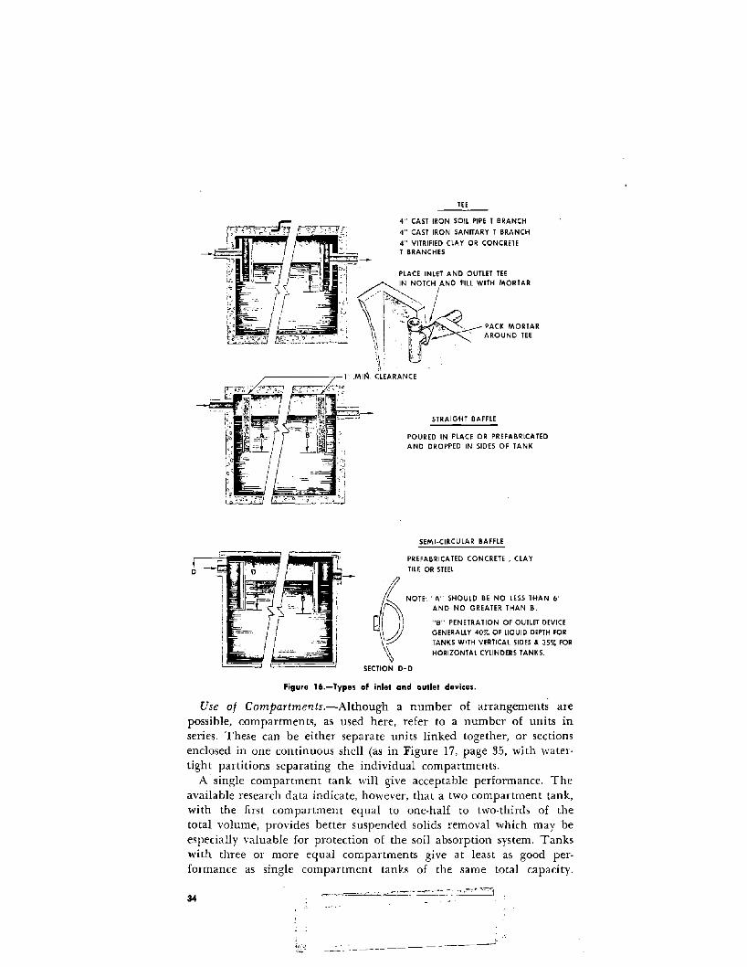
TEE
4" CAST IRON SOIL PIPE T BRANCH
4" CAST IRON SANITARY T BRANCH
4" VITRIFIED CLAY OR CONCRETET BRANCHES
PACK MORTARAROUND TEE
CLEARANCE
STRAIGHT BAFFLE
POURED IN PLACE OR PREFABRICATEDAND DROPPED IN SIDES OF TANK
SEMI·CIRCULAR BAFFLE
PREFABRICA TED CONCRETE, CLAYTILE OR STEEL
NOTE: "A" SHOULD BE NO LESS THAN 6"AND NO GREATER THAN B.
"B" PENETRATION OF OUTLET DEVICEGENERALLY 40% OF L10UID DEPTH FORTANKS WITH VERTICAL SIDES & 35% FORHORIZONTAL CYLINDERS TANKS.
SECTION 0-0
Figure 16.-Types of inlet and outlet devices.
Use of Compartments.-Although a number of arrangements arepossible, compartments, as used here, refer to a number of units inseries. These can be either separate units linked together, or sectionsenclosed in one continuous shell (as in Figure 17, page 35, with watertight partitions separating the individual compartments.
A'single compartment tank will give acceptable performance. Theavailable research data indicate, however, that a two compartment tank,with the first compartment equal to one-half to two-thirds of thetotal volume, provides better suspended solids removal which may beespecially valuable for protection of the soil absorption system. Tankswith three or more equal compartments give at least as good performance as single compartment tanks of the same total capacity.
34
-----)-.

Each compartment should have ~ mInImUm plan dimension of 2 feetwith a liquid depth ranging from 30 to 60 inches.
An access manhole should be provided to each compartment. Venting between compartments should be provided to allow free passageof gas. Inlet and outlet fittings in the compartmented tank should beproportioned as for a single tank. (See Figure 16, page 34). The sameallowance should be made for storage above the liquid line as in asingle tank.
9'-0"
PLAN
LONGITUDINALSECTION
Figure 17.-Precast septic tank.
'lorE, ALL FITTINGS 4" V.c.OUTLET FITTING SET 3"BELOW INLET FiniNG
4'-0"
SECTION A-A
General Information on Septic Tanks
Cleaning.-Septic tanks should be cleaned before too much sludgeor scum is allowed to accumulate. If either the sludge or scum approaches too closely to the bottom of the outlet device, particles willbe scoured into the disposal field and will clog the system. Eventually,when this happens, liquid may break through to the ground surface,and the sewage may back up in the plumbing fixtures. When a disposal field is clogged in this manner, it is not only necessary to cleanthe tank, but it also may be necessary to construct a new disposal field.
The tank capacities given in Table 5 on page 29 will give a reason-=-C~~:._- c' --." -'" -.·-·'~':':l
35
=

able period of good operation before cleaning becomes necessary. Thereare wide differences in the rate that sludge and scum will accumulatefrom one tank to the next. For example, in one case out of 20, the tankwill reach the danger point, and should be cleaned, in less than 3. years.Tanks should be inspected at least once a year and cleaned whennecessary.
Although it is difficult for most homeowners, actual inspection ofsludge and scum accumulations is the only way to determine definitelywhen a given tank needs to be pumped. When a tank is inspected, thedepth of sludge and scum should be measured in the vicinity of theoutlet baffle. The tank should be cleaned if either: (a) The bottomof the scum mat is within approximately 3 inches of the bottom ofthe oU,tlet device; or (b) sludge comes within the limits specified inTable 6 (see Figure 18, page 37).
Table 6.-Allowob/e sludge accumulation
Liquid depth
Liquid capacity
I I Iof tank, 21;2 feet 3 feet 4 feet 5 feetgallons'
Distance from bottom of outlet device to top of sludge, inches
750. ,.. 5 6 10 13900. 4 4 7 101.000 ...... 4 4 6 8
• Tanks smaller than the capacities listed will require more frequent cleaning.
Scum can he measured with a stick to which a weighted flap hasbeen hinged, or with any device that can be used to feel, au t thebottom of the scum mat. The stick is forced through the mat, thehinged flap falls into a horizontal position, and the stick is raiseduntil resistance from the bottom of the scum is felt. ,,yith the sametool, the distance to the bottom of the outlet device can be found (seeFigure 18, page 37).
A long stick wrapped with rough, white toweling and lowered to thebottom of the tank will show the depth of sludge and the liquid depthof the tank. The stick should be lowered behind the outlet deviceto avoid scum particles. After several minutes, if the stick is carefullyremoved, the sludge line can be distinguished by sludge particles clinging to the toweling.
In most communities where septic tanks are used, there are firmswhich conduct a business of cleaning septic tanks. The local healthdepartment can make suggestions on how to obtain this service.
36

Cleaning is usually accomplished by pumping the contents of the tankinto a tank truck. Tanks should not be washed or disinfected afterpumping. A small residual of sludge should be left in the tank forseeding purposes. The material removed may be buried in uninhabitedplaces or, with permission of the proper authority, emptied into asanitary sewer system. It should never be emptied into storm drainsor discharged directly into any stream or watercourse. Methods of disposal should be approved by the health authorities.
When a large septic tank is being cleaned, care should be takennot to enter the tank until it has been thoroughly ventilated andgases have been removed to prevent explosion hazards or asphyxiationof the workers. Anyone entering the tank should have one end of astout rope tied around his waist, with the other end held above ground
I~
-----~ /
fjii~~.~E:":L_. OUTlET
fl
I!I
MEASURING STICK ......... !FOR SLUDGE ----./" I
,H~f~,-'j,
TURKISH TOWELING ,""""r;: J'
,.j \~·"lr.j
~':-
WHITE TOWELING WILL BE BLACKENED
BY SLUDGE
[1 I'Ii:V'I MEASURING j:1 DEVICES Xi; FOR SCUM
J ii',I' :
T jl, I' lr;'NGE
f i !; \ 'V,)\""WEIGHT.....1..-, </R NOTE: MAKE MEASURING STICKS ABOUT 6' LONG
1
,I
NOTE, CLEAN WHEN A IS J" OR LESS, AND
WHEN B IS WITHIN THE LIMITS SPECIFIED
IN TABLE 6.
Figure lB.-Devices for measuring sludge and scum.
37

by another person strong enough to pull him out if he should beovercome by any gas remaining in the tank.
Grease Interceptors.-Grease interceptors (grease traps) are not ordinarily considered necessary on household sewage disposal systems. Thedischarge from a garbage grinder should never be passed through them.The septic tank capacities recommended in this manual are sufficientto receive. the grease normally discharged from a home.
Chemicals.-The functional operation of septic tanks is not improvedby the addition of disinfectants or other chemicals. In general, the addition of chemicals to a septic tank is not recommended. Some proprietary products which are claimed to "clean" septic tanks contain sodiumhydroxide or potassium hydroxide as the active agent. Such compoundsmay result in sludge bulking and a large increase in alkalinity, andmay interfere with digestion. The resulting effluent may severely damage soil structure and cause accelerated clogging, even though some temporary relief may be experienced immediately after application ofthe product.
Frequently, however, the harmful effects of ordinary householdchemicals are overemphasized. Small amounts of chlorine bleaches,added ahead of the tank, may be used for odor control and will haveno adverse effects. Small quantities of lye or caustics normally used inthe home, added to plumbing fixtures is not objectionable as far asoperation of the tank is concerned. If the septic tanks are as large asherein recommended, dilution of the lye or caustics in the tank willbe enough to overcome any harmful effects that might otherwise occur.
Some 1,200 products, many containing enzymes. have been placedon the market for use in septic tanks, and extravagant claims havebeen made for some of them. As far as is known, however, none hasbeen proved of advantage in properly controlled tests.
Soaps, detergents, bleaches, drain cleaners, or other material, as normally used in the household. will have no appreciable adverse effecton the system. However, as both the soil and essential organisms mightbe susceptible to large doses of chemicals and disinfectants, moderationshould be the rule. Advice of responsible officials should be soughtbefore chemicals arising from a hobby or home industry are dischargedinto the systems.
MiscellaneollS.-It is generally advisable to have all sanitary wastesfrom a household discharge to a single septic tank and disposal system.For household installations, it is usually more economical to providea single disposal system than two or more with the same total capacity.Normal household waste, including that from the laundry, bath, andkitchen, should pass into a single system.
Roof drains, foundation drains and drainage from other sources producing large intermittent or constant volumes of clear water shouldnot be piped into the septic tank or absorption area. Such large volumesof water will stir up the contents of the tank and carry some of the
38

solids into the outlet line; the disposal system following the tank willlikewise become flooded or clogged, and may fail. Drainage from garagefloors or other sources of oily waste should also be excluded from thetank.
Toilet paper substitutes should not be flushed into a septic tank.Paper towels, newspaper, wrapping paper, rags, and sticks may notdecompose in the tank, and are likely to lead to clogging of the plumbing and disposal system.
Waste brines from household water softener units have no adverseeffect on the action of the septic tank, but may cause a slight shortening of the life of a disposal field installed in a structured clay type soil.
Adequate venting is obtained through the building plumbing if thetank and the plumbing are designed and installed properly. A separatevent on a septic tank is not necessary.
A chart showing the location of the septic tank and disposal systemshould be placed at a suitable location in dwellings served by such asystem. 1!\Thether furnished by the builder, septic tank installer, or thelocal health department, the charts should contain brief instructionsas to the inspection and maintenance required. The charts should assistin acquainting homeowners of the necessary maintenance which septictanks require, thus forestalling failures by assuring satisfactory operation. The extension of the manholes or inspection holes of the septictank to within 8 inches of the ground surface will simplify maintenanceand cleaning.
A bandoned septic tanks should be filled with earth or rock.
INSPECTION
After a soil absorption system has been installed and before it is usedthe entire system should be tested and inspected. The septic tankshould be filled with water and allowed to stand overnight to checkfor leaks. If leaks occur; they should be repaired. The soil absorptionsystem should be promptly inspected before it is covered to be surethat the disposal system is installed properly. Prompt inspection beforebackfilling should be required by local regulations, even where approvalof plans for the subsurface sewage disposal system has been requiredbefore issuance of a building permit. Backfill material i should be freeof large stones and other deleterious material and should be overfilleda few inches to allow for settling.
39


Part II
Septic Tank - Soil Absorption
Systems for Institutions)
Recreational Areas) and
Other Establishments
INTRODUCTION
The septic tank system is utilized in providing sewage treatment anddisposal for many types of establishments, such as schools, small institutions, motels, rural hotels and restaurants, trailer parks, housingprojects, large private estates, and camps, where larger quantities ofsewage are involved than are discharged from an individual home. Ingeneral, the usefulness of the septic tank system decreases as the sizeof the establishment served increases. Lack of competent sanitary engineering advice in the development of such systems generally will leadto failures, excessive costs, and a multitude of troubles. The soundestadvice available to anyone contemplating such a system is the earlyretention of competent sanitary engineering consultation, whose firstdetermination should be the suitability of this method of sewage disposal for the proposed establishment.
Any institutional septic tank system must incorporate appurtenancesand supplemental features of design to meet the requirements of theestablishment and varying site conditions. These can be generally successful when appropriate experience, study, and planning are employedin the choice and development of such a system. This manual cannotpresent all of the results of experience gained in the design and operation of such systems, but describes the most generally successful procedures and practices as a guide to engineers designing them.
While many effluents from institutional septic tanks are disposed ofby soil absorption methods, others are discharged to available watercourses after suitable treatment. When soil absorption systems are contemplated, it is essential, as described in Pait 1, to determine the characteristics and suitability of the soil as the first step toward design. Asa matter of fact, the wise builder of an establishment will explore thisfeature on a contemplated site before the site is purchased. After the
,i;'7·~~<·~,·~'t;.~>_.~-;/~~~.:~- : ~. "'.,' - . J
:/·Precedihg>page·>bJ~nk··· j41

percolation tests are completed, the quantity of sewage to be treatedmust be--estTirl)tW~ to'd,~~~rn:t{qe!:_¥~ size and capacities of the disposalJ·nits'.~"'~'.":"': .,..><....-'~ IJ l- \..~:r'~./;~.~:!~:r:j-JJ2i...!.j l;
ESTIMATES OF SEWAGE QUANTITIES
Where there are water meters in existing buildings, the quantity ofsewage may best be estimated from the recorded meter readings.
In using water meter readings for estimating the quantity of sewageto be contributed, some allowance should also be made for maximumconditions that may not be readily apparent from the readings. Forexample, water consumption by an ordinary family of four in an apartment building may average 48 gallons of water per person per day overa period of 3 months, but actually range from perhaps 30 gallons perperson on certain days to something in excess of 80 gallons per personon days when water consumption is heaviest, as on washdays. Besidesthese peak loads, some allowance should be made for the sewage contributed by occasional guests. Therefore, when computing sewage flowsfrom average meter readings, a minimum factor of safety of about 25percent should be allowed to cover the range of variations. Accordingly,the design of a disposal system for the apartment house referred to,where the average usage is 48 gallons per person per day, should bebased upon a computed maximum usage of at least 60 gallons perperson per day.
Conversely, unusually high meter readings may be caused by lawnserinkling or by leakage of water that does not enter the disposal system. Due allowances should be made for abnormalities of this kind.
Where measurements of water consumption are not possible, aswhere water meter records are not available, or where disposal facilitiesare being planned for a new building, it is necessary to use othermethods of estimating the amount of sewage to be discharged. One wayis to base the estimated flow on the number of bedrooms, as in Part 1.Another way is to compute the flow on the basis of the number andkinds of plumbing fixtures. If the building is used as a restaurant, thenumber of patrons or the number of meals served may be the best criterion. The competent designer will base his estimates upon a combination of the various influencing factors. He will consider each case onits own merits, especially when disposal facilities are being designed fora large institution where the cost of construction will amount to a considerable sum. If definite information and accurate water measurementsare not available, the quantity of sewage may be estimated from experiences at establishments similar to that for which the new sewage disposal facilities are intended. Table 7 (page 43) may be helpful in suchcases. i
The quan tities listed in the table are merely the best averages available at this time, and they should be modified in localities or estab
~,
lishments where experience inditates a need for so doing."\-'-.l_~
42 '...:, )
. i.
{ "

It is sometimes economical and advisable to construct separate disposal systems for different types of wastes at a given establishment. Thedecision as to the number of disposal systems may be influenced byconditions of terrain, topography, and locations of the buildings contributing to the wastes. At large camps, for example, and at some resorts, kitchens and central dining facilities may be located at appreciable distances from the barracks or cottages and cabins. Under suchcircumstances, the kitchens may be provided with separate disposalsystems, including facilities for the removal of grease ahead of theseptic tank.
Table T.-Quantities of sewage flows
Type of Establishment
Airports (per passenger)Apartments-multiple family (per resident)Bathhouses and swimming poolsCamps:
Campground with central comfort, stations"Vi th flush toilets, no showersConstruction camps (semi·permanent)Day camps (no meals served)Resort camps (night and day) with limited plumbingLuxury camps
Cottages and small dwellings with seasonal occupancyCountry clubs (per resident member)Country clubs (per non·resident member present)Dwellings:
Boarding housesadditional for non-resident boarders
Luxury residences and estatesMultiple family dwellings (apartments)Rooming housesSingle family dwellings
Factories (gallons per person, per shift, exclusiveof industrial wastes)
Hospitals (per bed space)Hotels with private baths (2 persons per room)Hotels without private bathsInstitutions other than hospitals (per bed space)Laundries, self-service (gallons per wash, i.e., per
customer)Mobile home parks (per space)Motels with bath, toilet, and kitchen wastes
(per bed space)Motels (per bed space)Picnic Parks (toilet wastes only) (per picknicker)Picnic parks with bathhouses, showers, and flush toiletsRestaurants (toilet and kitchen wastes per patron)!,
Gallons Per Person Per Day(Unless Otherwise Noted)'
56010
3525501550
10050
10025
5010
15060407fj
3!i250+
6050
125
50250
5040
51010
43

Table 7.-Continued
Type of Establishment
Restaurants (kitchen wastes per meal served)Restaurants additional for bars and cocktail loungesSchools:
BoardingDay, without gyms, cafeterias, or showersDay, with gyms, cafeteria, and showersDay. with cafeteria, but without gyms, or showers.
Service stations (per vehicle served)Swimming pools and bathhousesTheaters:
Movie (per auditorium seat)Drive-in (per car space)
Travel' trailer parks without individual water andsewer hook-ups (per space)
Travel trailer parks with individual water andsewer hook-ups (per space)
\Vorkers:Construction (at semi-permanent camps)Day, at schools and offices (per shift)
Gallons Per Person Per Day(Unless Otherwise Noted)
32
1001525201010
55
50
100
5015
Separate systems may also be used for community bathhouses. Whenthis is done, the total per capita flow must be broken down into itscomponent patts, and some allowance should be made for the amountof sewage tributary to the differen t disposal systems. Table g (below)illustrates how this may be done where there are no definite data as tothe exact distribution of flow.
Table B.-Estimated distribution of sewage flows, in gallons per day per person
Type of. Waste Volume, gallons per day per person
Total Flow (gallons). 30 40 50 75 100
Kitchen wastes '0 7 10 10 15Toilet wastes 15 15 20 25 30Showers, washbasins, etc. 15 18 20 25 35Laundry wastes '0 '0 10 15 20
1 No wastes from these uses.
Example: In a household contributing 75 gallons of sewage per day per person, as;hown in column 4, an average breakdown for each of the four types of wasteslisted might be about 10 gallons per day per person for kitchen wastes; 25 gallons
44

per day per person for toilet wastes; 25 gallons per day per person for shower wastes,bathtubs, and washbasins; and about 15 gallons per day per person for laundrywastes.
For certain types of new establishments, the designing engineer maybe unable to obtain from his clients accurate estimates as to the number of patrons to be served by the disposal facilities. This is particularlytrue in the case of restaurants and at recreational places, such as picnicareas, country clubs, and the like. In such cases, computations and estimates may best be made from the number of plumbing fixtures installed. Table 9 indicates average values for quantities of sanitarywastes per fixture at country clubs with modern plumbing.
Table 9.-Sewage flow from country clubs
Gallons per Gallons perType of fixture day per Type of fixture day per
fixture fixture
Showers. 500 Toilets. 150Baths.. 300 Urinals. 100Lavatories ... 100 Sinks ... 50
Estimates of sewage quantities from golf clubs should be checked andcalculations based on the weekend population. Allowances of 10 gallonsper person for showers and 7 gallons per person for toilet and,kitchenwastes, both for the average weekend population, have been foundreasonable.
Table 10 shows one method used in estimating the amount of sewagedischarged hourly during the hours when public parks are open. Similar figures may be used for fairgrounds, carnivals, ball parks, etc.
Table IO.-Sewage /low at public parks
[During hours when park is open]
Gallons per Gallons perType of fixture hour per Type of fixture hour per
fixture fixture
Flush toilets. 36 Showers .. 100Urinals 10 Faucets 15
ESTIMATES OF SOIL ABSORPTION AREAS"Vith information from percolation tests and with due consideration
to the results of test borings or subsurface explorations, as explained in
45

Part I and Appendix A, the rate at which sewage may be applied to asoil absorption system may be taken from Table lIar from the carre·sponding curve in Figure 19 (see page 47).
Table 11.-A/lawab/e rate of sewage application to a soil absorption system
Maximum rate of ~Iaximum rate ofsewage application sewage application
Percolation rate (time (gallons per square Percolation rate (time (gallons per squarefoot per day)' for foot per day)' forin minutes for water absorption in minutes for water absorptionto fall I inch) trenches,' seepage to fall I inch) trenches,' seepagebeds, and seepage beds, and seepage
pits 3 pits 3
I or less .. 5.0 10.. .. .. ..... ... 1.62. ........ 3.5 15 .. . 1.33 ..... ........... 2.9 30 '. 0.94 ... .. ...... 2.5 45' . 0.85. ......... "." 2.2 60' ' .. . .......... 0.6
'Not including eliluents from septic tanks that receive wastes from garbagegrinders and automatic washing machines.
• Absorption area is figured as trench bottom area, and includes a statistical allow-ance for vertical sidewall area.
3 Absorption area for seepage pits is effective sidewall area.• Over 30 unsuitable for seepage pits.'Over 60 unsuitable for absorption systems.
Table II and the curves in Figure 19 do not allow for wastes fromgarbage grinders and automatic washing machines. Discharge fromthese appliances to an institutional septic tank system calls for extracapacity of 20 and 40 percent, respectively, over the calculated absorption area values. If both of these appliances are installed, the absorptionarea should be increased by about 60 percent over the calculated value.Part I allowed for these types of waste in giving specifications for smallhousehold systems, but they may never occur in institutional effluents,such as those from factories and offices. Other institutions, such as acountry club or drive-in theatre with eating facilities, may contributewastes from garbage grinders, but not from automatic washing machines. As previously emphasized, all institutions should have theirsystems designed by an engineer who is competent to place properevaluations on the kind of wastes to be contributed.
Use of Table II is demonstrated in the following examples, whichillustrates the design for the two types of soil absorption systems. Foreach example assume: 5,000 gallons of sewage per day to be disposedof; percolation rate, 1 inch in 5 minutes.
46

_\. Q= 5 For standard trenches or seepage pits-y'fi1/I"""-..JI
IIII1
:zQ Bt=o-""1:-.....
::t:::::;-CI-ClIl:""I: .......... -e.::t - 6""I: 03= Q
..... .......,., .......... ClIl:""I:Q :::>..... c:r-..,., 4""I: ........ .......... -...... ..,.,-:z
""I: Q
3= ............Q ""I: 2...... e.::t......""I:
oo 10 20 30 40 50
PERCOLATION RATE IN MINUTES PER INCH (tl60
Figure 19.-Graph showing relation be.ween percolation rate and allowable ra.e atsewage applica.jon.
Example I.-Absorption Trenches:Standard trench, 2 feet width.5,000 gal./ day --;- 2.2 gal./sq. ft./day = 2,270 square feet of absorp
tion area required.2,270 --;- 2 sq. ft./linear ft. = 1,135 feet of trench required.
With garbage grinder onl}'-1,135 + .20 (1,135) = 1,362 linear feet.With automatic washing machine only-1,135 + .40 (1,135) = 1,589
linear feetWith garbage grinder artd automatic washing machine-1,135 + .60
(1,135) = 1,816 linear feet.Example II.-Seepage Pits:
Seepage pit 10 foot diameter; depth of effective absorption area 25feet; let d = effective depth of pit in feet; D equal pit diameter in feet.Effective sidewall area equals total area needed.7rD(d) = 2,270 sq. ft.3.14 (10) (d) = 2,270.Solve for d, effective depth of pit = 72 ft.Obviously, more than one pit is required.Design for 3 pits, lOft. in diameter.
72 --;- 3 = 24 ft.Use 3 pits, 10 ft. in diameter with an effective depth of 24 ft.
47

With garbage grinder only-3.I4 (10) (d) = 2,270 + 2,270 (.20) = 2,724sq. ft.
Solve for d = 86.4 ft. Use 4 pits, 10 ft. in diameter with an effectivedepth of 21.6 ft.
With automatic washing machine only-3.14 (10) (d) = 2,270 + 2,270(.40) = 3,178 sq. ft. Solve for d = 101 ft. needed. Use 5 pits, 10 ft.in diameter with an effective depth of 20.2 ft.
Wi th garbage grinder and automatic washing machine-3.14 (10) (d) =2,270 + 2,270 (.60) = 3,632 sq. ft. required. Solve for d = 115.7 ft.required. Use 5 pits, 10 ft. in diameter with an effective depth of23.1 ft.
BUILDING SEWERS
The building sewer or house sewer is the pipeline carrying sewagefrom the building or house drain to a, private sewer, public sewer,septic tank, or other point of disposal. It usually extends from a point3 feet outside the building, where it is connected to the building drain.
The building sewer should be constructed of cast iron, vitrified clay,concrete, bituminized fiber, asbestos cement, or other durable material.All joints in the sewer line should be watertight and rootproof. Thegrade of the building sewer should be at least 2 percent (2 foot fall per100 feet, or Y-i inch per foot) except for the 10 feet immediately preceding the septic tank, where it should not exceed 2 percent. Buildingsshould be planned so that a proper slope of the building sewer can beobtained. Where the terrain is extremely flat, however, it may be advisable to allow a slope of only 6 inches per 100 feet, or 0.5 percen t(see Table 12, page 49).
The size of the pipeline to a septic tank is generally dependent uponits ability to allow objects 'to pass, and upon its capacity to conducthigh flows for short periods, rather than upon its capacity in relationto the average flow. No building sewer serving water closets should beless than 4 inches in size. The relationship of minimum sizes to theslopes and to the number of fixture units is indicated in Table 12.
Cleanouts should be provided at the junction of the building drainand building sewer and at each change in direction of the buildingsewer greater than 45 0 They should also be provided at intervals ofnot more than 100 feet. That portion of the sewer line within 50 feetof any well or suction line from a well, or within 10 feet of anydrinking water supply line under pressure or within 5 feet of anybasement foundation should be durable, corrosion resistant, root proof,and so installed as to remain water tight. Cast iron or other highstrength pipe should be required wherever the line crosses under driveways with less than 3 feet of earth cover. While no general statementcan be made to cover all cases, Table 2 (page 10) should be followedin locating components of the sewage disposal system. Where sewerlines are in the vicinity of trees or dense shrubs; and are not can-
48

Table 12.-Maximum number of drainage fixture units 1 served by building sewer 01
indicated size and slope
Pipe slope (inch per foot)l\Iinimum pipe diameter,
inchesYJ.6 % 14 1h
L. 180 216 2505. 390 480 5756. 700 840 1,0008. 1,400 1,600 1,920 2,300
10.. 2,500 2,900 3,500 4,20012 3,900 4,600 5,600 6,700
1 A drainage fixture unit is a quantity in terms of which the load producingeffects of different plumbing fixtures on the plumbing system are expressed on somearbitrarily chosen scale. For example, a small lavatory is rated as 1 fixture unit; akitchen sink, 2; a bathtub, 2; a tank operated water closet, 4; and a valve operatedwater closet, 6. A table of ratings from the United States of America Standards Insti·tute National Plumbing Code is given in Appendix D, page 85.
structed of cast iron as indicated above, the joint should be made ofspecial, root resistant construction.
Bends ahead of the septic tank should be limited to 45 ° or lesswherever possible. If 90° bends cannot be avoided, they should bemade with two 45° ells, or a long sweep quarter curve or bends.
COLLECTION SYSTEMS
At institutions where there are a number of buildings, it may beadvisable to provide a system of sewers for the collection, transportation, and possibly the pumping of sewage to the septic tank. In general,the collection system should be designed for a capacity expected to beadequate for at least one decade, and preferably two. It is usually advisable to design the sewers with capacities, when running full, of notless than 10 times the average estima ted flow of sewage.
Institutional sewers carrying raw or untreated sewage should be atleast 6 inches in diameter arid have slopes of at least 1;8 inch to thefoot (1.0 percent). In very small installations, 4 inch sewers at 'l4 inchper foot (2 percent) may be used to carry raw sewage, and 4 inch sewerswith slopes of Vs inch per foot are acceptable for carrying settled sewage. All sewers should be designed and constructed with ):1ydraulicslopes sufficient to give mean velocities, when flowing full, of not lessthan 2.0 feet per second, based on Kutter's or Manning's formula usingan "n" value of 0.013. Use of other practical "n" values will be permitted by the plan reviewing agency for longer pipe sections if deemedjustifiable on the basis of research or field data presented.
Under exceptional conditions, if full and justifiable reasons are given,
49

and if special arrangements are available or will be provided forflushing, velocities as low as 1.6 feet per second may be permi tted. Ingeneral, the following minimum grades should be provided:
Percent8 inch sewers ". " 0.40
10 inch se'wers.,. 0.2812 inch sewers ". '" .. 0.22
The use of a larger sewer to take advantage of the lesser minimumslope, when there is not enough sewage to fill the sewer nearly one-halffull, is generally not advisable. The use of asbestos cement pipe orenamel lined or cement lined cast iron pipe is suggested under suchconditions.
Sewer lines must be laid on straight alignment and uniform slopebetween manholes. Manholes should be placed on sewers at all pointsof change of slope or alignment, at the upper ends of all sewer lines,and otherwise at intervals not greater than 400 feet. If the topographyis very uneven and frequent changes in alignment and slope are necessary, a limited number of lampholes may be substituted for manholesat such points of change. Not more than one lamphole should beplaced between two successive manholes.
There must be no physical connection between a public or privatepotable water supply system and a sewer, sewage disposal system, orappurtenances thereto, which would render possible the passage of anysewage or polluted water into the potable water supply.
GREASE TRAPS
Premature failures of septic tank systems are sometimes due to accumulations of grease within the tanks. Sewer lines frequently clog because of grease collections. Where grease traps are used, the grease mustbe removed at frequent intervals. Grease traps may be used on kitchenwastelines from institutions, hotels, restaurants, schools with lunchrooms, and other places where the volume of kitchen wastes is large.After passing through the grease trap, the kitchen wastes must still betreated in the septic tank before being discharged to the disposal area.Wastes from garbage grinders should not be discharged to a greasetrap. (Grease traps have been used with some degree of success for theremoval of lints and fines from laundry wastes, but better results maybe obtained by increasing the size of the septic tanks receiving suchwastes, or by the use of rock filters to remove the lint.)
Location
Grease traps should be placed at a location that is readily accessiblefor cleaning, and close to the fixture discharging greasy wastes.
50

Construction Details
The most important considerations for design of grease traps are:1. Capacity of the trap.2. Facilities for insuring that both the inlet and outlet are properly
trapped.3. Ease and convenience with which the traps can be cleaned and
the accumulated grease removed.4. Inaccessibility of the traps to insects and vermin.5. Distance between inlet and outlet, which should be sufficient to
allow gravity differential separation of the grease, so that it will notescape through the outlet.
The principles are illustrated in Figure 20.
CLAY TILEPIPE
Ii'~~=-OUTLET
SEALED IN CONCRETE
SECTIONCLAY TILE PIPE
SECTIONCONCRETE BOX
INLET
PLAN(TOP REMOVED I COVER OF REINFORCED
/CONCRETE, ALUMINUM~ OR CAST IRON
~~~ Ii~~~
'.. ~ ...2" INLET FROM'KITCHEN SINK
Figure 20.-Typical grease traps. 51

Flow control fittings should be installed on the inlet side of smallertraps to protect against overloading or sudden surges from the sink orother fixtures. Venting is not necessary in the large, outdoor traps,where siphonage of the contents can be prevented by providing outletsof liberal size. Where efficient removal of grease is very important, usehas been made of an improved 2 chamber trap which has a primary(or grease separating) chamber and a secondary (or grease storage)chamber. By placing the trap as close as possible to the source of wastes,where the wastes are still hot, the separating grease at the surface maybe removed by means of an adjustable weir and conveyed to the separate secondary chamber, where it accumulates, cools, and solidifies.
Capacity
Selection of size of traps should be based on verified efficiency ratingsand flow capacities. The required flow capacities should be based uponthe number and kind of sinks or fixtures discharging to the trap. Inaddition, a grease trap should be rated on its accumulated grease capacity, which is the amount of grease (in pounds) that the trap canhold before its average efficiency drops below 90 percent. It is commonly regarded that the grease retaining capacity in pounds shouldequal at least twice the flow rating in gallons per minute. That is tosay, a trap rated at 20 g.p.m. should retain at least 90 -percent of thegrease discharged to it until it holds at least 40 pounds of grease. Mostmanufacturers of commercial traps rate their products in accordancewith this procedure.
. Recommended minimum flow rate capacities of traps connected todifferent types of fixtures is given in Table 13.
Table 13.-Recommended ralings for commercial grease Iraps
Grease Recommendedmaximum
Rate of retention capacity ofType of fixture flow, in capacity fixture con-
g.p.m. rating, in nected to trap,pounds in gallons
Restaurant kitchen sink... 15 30 37.5Single compartment scullery sink. 20 40 50.0
Double compartment scullery sink 25 50 62.5
2 single compartment sinks..... , . 25 50 62.52 double compartment sinks ... 35 70 87.5
Dishwashers for res tauran ts:Up to 30 gal. water capacity. 15 30 37.5
30 to 50 gal. water capacity ... 25 50 62.5
50 to 100 gal. water capacity.. 40 80 100.0
52

A net capacity of 2Y2 gallons per person has been found large enoughto hold the flow from one meal long enough to accomplish propergrease separation. The minimum allowable capacity should be about125 gallons for small installations serving up to 50 people with proportionately larger capacities for larger populations. As with septic tanks,however, it is generally good economy to build grease traps somewhatoversize. For installations too small to justify a 125 gallon grease trap,best results can usually be obtained by applying available funds to anoversized and properly fitted septic tank.Operation
In order to be effective, grease traps must be operated properly andcleaned regularly to prevent the escape of appreciable quantities ofgrease into the septic tank. The frequency of cleaning at any giveninstallation can best be determined by experience based on observationover selected typical periods of use, Generally, cleaning should be donewhen 75 percent of the grease retention capacity is filled with accumulated grease.
Grease traps must be kept tightly covered to prevent odor nuisancesand to exclude insects and vermin. Grease removed from the traps isdisposed of by burial. (It may be used for making soap and glycerine,and for other manufacturing purposes, when economically feasible orbecause of shortages of such materials during wartime.)
SEPTIC TANKS FOR INSTITUTIONAL SYSTEMS
As explained in Part I, septic tanks of two compartments give betterresults than single compartment tanks. Although single compartmenttanks are acceptable for small household installations, tanks with twoor more compartments should be provided for the larger institutionalsystems. Tanks with more than two compartments are installedinfrequently.
The compartments should be separated by walls containing ports orell fittings at proper elevations as discussed in Part I, pages 30 and 32.In the selection of these elevations, the same general principles applyas in the design of outlet fittings. Vents for the passage of gases fromone compartment to another should also be included.
In a two compartment tank, the compartment nearest the outlet isused both as a settling basin and as an observation well. The relativeabsence of solid material in the second compartment serves as an indiocation that the tank is functioning properly, although it may not serveas an index of conditions within the first compartment, and it is some·times advisable to clean the first compartment before accumulations inthe second become appreciable. In a two compartment tank, the firstcompartment should have a capacity of at least two to three times thecapacity of the second compartment.
"VVhatever the number of compartments, means should be providedfor gaining access to each compartment, and for measuring the depths
53

of sludge and scum at the outlet device as illustrated in Figure 18(page 37). Unless tops of septic tanks are neilr the surface of the ground,as in Figure 15 (page 33), manholes should be provided as required tofacilitate ingress and egress, A single manhole above a dividing wallmay be used for gaining access to two compartments in a multicompartment tank. Manholes are also desirable over the inlet and outletdevices.
Alternate designs for manholes are shown in Figure 14 (page 32). Thedesign selected will depend on whether or not the manhole cover mustbe flush with the surface, and on the anticipated traffic loadings overthe area.
The effect of a multiple compartment tank can be accomplished byusing two or three wnks in series, A better construction arrangement,particularly for medium or large installations, is to connect special tanksections together into a unit having single end-walls and two compartments. A unit of four precast tank sections forming two compartmentsis shown in Figure 21.
II-~ - - - - -i - - -- - - - --, - --
~:\, I
I -. I
I '~~ I I1- _ _ __ _ _ f- J
, I- ,- - -"/C- -I
~: '~'\\II~j \~II_______ ' J
'f't;~:-o-:o~:::::r· 'j~"" i._ c;:;p;aa #s;:tp/"",,,,,,",,,,j
, .- -. l::4 '.: ~'~.:--:-;'?:~?t!-:;~::;. &,J;li:;J;l."'iIJ~l-:I~
-~.
SECTION
Figure 21.-Baitery of four precast reinforced-concrete sepiic-Iank sections.
Capacities
The net volume or effective capacity below the flowline of a septictank, for flows up to 500 gallons perday, should be at least 750 gallons.For flows between 500 and 1,500 gallons per day, the capacity of thetank should be equal to at least 1J;2 days' sewage flow. With flowsgreater than 1,!500 gallons per day, the minimum effective tank capacityshould equal 1,125 gallons plus 75 percent of the daily sewage flow; or
V = 1,125 + O.75Qwhere V is the net volume of the tank in gallons and Q is the dailysewage flow in gallons. If garbage grinders are used, additional volumefor extra sludge storage may be desired to minimize the frequency ofcleaning,
54 D.- -

Recommended tank capacities for flows up to 14,500 gallons per daymay also be obtained from Figure 22 (below). For higher flows ofup to about 100,000 gallons per day, Imhoff tanks may be more satisfactory ·than septic tanks for primary treatment. For flows above100,000 gallons, still other types of sedimentation tanks may be moreeconomical. These fall within the category of design for municipalsystems, and are beyond the scope of this manual.
DOSING TANKS
When the quantity of sewage exceeds the amount that can be disposed of in about 500 lineal feet of tile, a dosing tank should be usedin conjunction with the septic tank, in order to obtain proper distribu-
0
0
/"17
0
V0
V,
/0
L/ V =1125 + 0.7500
/0 y
/'0
--- --- --- ---7f0 /
V III
V I
/'II
/V I
I0 I
V I
) 1---- V =1.5 0 II
I II
0 I
5,00
6,00
3,000
4,000
2.00
13,00
12,00
1,000
8,00
10,00Vlze:>.....Ci! 9,00t!J
:!:
11 ,00
> 7,00l-e:;.."....,""z..l-
e:>...e>::
§e>::
1000 2000 3000 4000 5000 6000 7000 8000 9000 10,000 11 ,00012,000 13,00014,000
SEWAGE FLOW. "0". IN GALLONS PER DAY
Figure 22.-5eptic-tank capacities for sewage flows up to 14,500 gallons per day.
tion of sewage throughout the disposal area and give the absorptionbed a chance to rest or dry out between dosings. Rest periods are alwaysadvantageous, especially when the soil is dense. The dosing tankshould be equipped with an automatic siphon which discharges thetank once every 3 or 4 hours. The tank should have a capacity equal~to about 60 to 75 percent of the interior capacity of the tile to bedosed at one time.
55

Where the total length of tile lateral exceeds 1,000 feet, the dosingtank should generally be provided with two siphons dosing alternatelyand each serving one-haU of the tile field. The proper design of dosingdevices involves hydraulic problems and head losses which must becarefully considered. Dosing siphons require operating heads rangingfrom about 5 feet down to a minimum of 1 or 2 feet. and repeatedstudies of different layouts may be necessary in order to arrive at aneconomical design in which available head is conserved and best use. ismade of existing conditions of topography. Specal siphons are manufactured for low head losses. For details and capacities, the manufacturers' bulletins should be consulted.
Special care m list be taken in the installation of siphons. All dimensions and elevations should be carefully followed, and no changesshould be made without prior approval by the engineer or manufacturer. Tests should be made to determine that there are no air leaks,eIther in the piping or bell casting, and if leaks are found, they shouldbe repaired. Leaks may be detected by filling the dosing tank withwater, to a point where the bell and piping connections are covered,and observing the water surface for rising bubbles. New siphons shouldbe primed by filling with water when the system is first started anyway,and the tests for leakage can be made at that time.
When properly installed, automatic dosing siphons will give satisfactory service. They contain no moving parts and are more foolproofthan any dosing device that depends upon moving parts for its operation. Figure 23 (page 57) shows a septic tank and dosing compartmentwith alternating siphons, as illustrated in suggested plans and designsdeveloped by a State health department.
A typical layout plan or "general plan" of a system using alternatingsiphons is illustrated in Figure 24 (page 58).
Separate siphon compartments already equipped with siphons aremade by some manufacturers. Duplex siphon compartments equippedwith two siphons which operate alternately are also prefabricated.
1£ the head available is inadequate to permit the use of a siphon,intermittent pump operation may be used to obtain proper dosing ofthe field, as shown in Figure 25 (page 60). The pump discharge linesmay be inter-connected to obtain flexibility and to facilitate operationswhen one pump is down for repairs.
SAND FILTER TRENCHES
In permeable soil, absorption trenches of the type illustrated inFigure 5 (page 12), seepage beds, or seepage pits as illustrated in Figure10 (page 24), provide the best underground method of disposing ofthe effluent from a septic tank. The absorption trench is preferred, andis required in SOlne areas where seepage pits are prohibited. In soilthat is relatively impermeable, however, neither absorption trenches,seepage beds nor seepage pits are satisfactory. They become more ex-
56

r- ft- - --<-- - - - - _1':0-- IT - --
I II I' IIi[] II,
-1-, r~; Ir::t:r I-( cl, , UI_' II,_ SEPTIC DOSI NG, 'II TANK, -- II II CHAMBER
L lj. _-.,- ~ JJ -::-Il- _
PlAN
SLUDGEDRAIN
SECTION INOr TO SCALEj
Figure 23.-5eptic tank and dosing tank with alternating siphons.
pensive as the soil permeability decreases, and may not be economicallyfeasible when the percolation time exceeds 30 or 40 minutes per inch.The exact point at which they are no longer desirable will dependlargely upon the relative costs of labor and material in the localitywhere the disposal system is to be constructed. The decision as towhether to use absorption trenches, seepage beds or seepage pits mayalso depend upon the area available. V\There land is at a premium, absorption trenches become less attractive. They begin to require excessive areas when the percolation time exceeds 20 minutes per inch.
When absorption trenches, seepage beds, and seepage pits are impractical for institutional or similar use, the possibility of treating thetank effluent in subsurface sand filter trenches may be considered.
The filter trenches are somewhat similar to absorption trenches, themajor difference being that the filter trenches are deeper, generallysomewhat wider, contain an intermediate layer of sand as filtering material, and are provided with underdrains for carrying off the filteredsewage. The tank effluent is not absorbed, except to a limited extent.It is simply filtered and must be disposed of when it leaves the trench.
- -- _.~--- --r-;
f(Irl:
'- ='------..---- -T '
57

[
WELL 6" DIA.-140' DEEP THRONEAREST OTHER WELL 200 UGH SAND AND LIMESTONE'
YDS. NORTH
-\-=-~ ==----=--~===-=:-~.:=--------~---::-~=::-"---~ -b""", z --"---~0, 0 ,----, - - '.i '0 G' :j l r----,--, ~--.-"
'Pc<: " I'
W.r~",/,,r. , '. "I lS3~ ~ ~,., . ------- 'l' 1> ~ /" HOTEl ,,:.1 I
"" "'/',0' '" iL-l I"'/'1--"," __ ~~M.S:..~S BATHS: 25 TOILETS I
153 -,- --- --------~ ,I
\ '" """,N WAm "N'/ '" "" .. i
\
GREASE TRA~(150 GAL.) / SLOPE 2% 152
GA"AG< G"~'" "N' ."NO" II
Figure 24 T.- ypi~al layout plan of" a su bsu rfa~e sewage-disposal system.
58

tank
Lineal ft.of trenchper field.for future
600 gal. per day125 gal. per day50 gal. per day
150 gal.
1113= 5572
720 gal. per day3,895 gal. per day4,046 gal.5,000 gal. capacity
= 2,400 gal. per day
= 7 lines of (4") laterals required for each field.
DESIGN DATA FOR DISPOSAL ILLUSTRATED IN FIGURE 24Hotel
26 rooms total20 rooms with private baths X 2 persons per room
X 60 gal. per person per day6 rooms with connecting baths X 2 persons per room
X. 50 gal. per person per day5 daytime employees X 25 gal. per person per day2 night employees X 25 gal. per person per dayKitchen wastes: 60 persons X 3 meals per day
X 4 gal. per mealTotal daily sewage flowRequired septic tank capacity (from Fig. 22)
(In this case, consideration should be given to using awhich will require less frequent cleaning.)Required grease trap capacity 60 persons X 2V2 gal.Percolation test: 6 min. per inch drop.Allowable rate of sewage application (from Fig. 19)
Number of separate absorption fields
2.1 gal. per sq. ft.per day
~_- 1855 ft2.1 ' sq..
371 sq. ft.2,226 sq. ft.24 inches (2.0 ft.)
= 2226 = 1,113 fL2
As stated in the section on Dosing Tanks, where the length of trench exceeds1,000 feet a dosing tank should be used with alternating siphons, each serving onehalf of the absorption field.Total trench length
Total trench length
Trench area required for normal wastes
Plus 20% additional for wastes from garbage grinderTotal trench area requiredDesired trench width
80 ft. lengths can best be worked into available disposal area with roomadditions if needed.
55780
Preferred dosing tank capacity = 75 percent of interior capacity of tile to be dosedat one time.
4" tile = 3.14 X 22 X 12 = 151 cu. in. per ft.
151 cu. in./ft. X 0.75 O· 4" I/f . d d' k . ( 05)= .;;T ga. t. requlfe osmg tan capacity say .231 cu. in./gal.
Thus the capacity of the dosing tank should be 0.5 gal./ft. X 7 X 80 ft. = 280gallons.
For this reason, filter trenches are properly regarded as a means ofsewage treatment, and not sewage disposal. They accomplish a highdegree of purification, however, and the sewage effluent coming from afilter trench that is properly designed can sometimes be disposed ofwithout further treatment, by discharging into ditches, small streams,or dry streambeds. If the receiving stream contributes to a source ofwater supply, shellfish growing area, or recreational area, chlorinationshould be required as hereinafter explained. In some jurisdictions,chlorination is required for all effluents from sand filters.
59

---------,---,-----------,-----...,..
PUMP-DOSING(HAMBEll
Figure 2S.-Seplic lank and pump-dosing chamber.
Approval should be obtained from the State or local health department before filter trenches are installed. This method of sewage treatment becomes less economical and less desirable as the quantity ofsewage and the required area increase. Subsurface sand filters may beneeded for larger installations.Construction Features
Typical details of an underdrained sand filter trench are shown inFigure 26 (page 61). For all year service, filter trenches should be designed for filtration rates as given in Table 14_
Table 14.-Loading rates for subsurface filrers
Type of service Area Requirements
Without garbage grinder or automatic washer.With garbage grinder'With automatic washing machineWith both garbage grinder and automatic washer
Gallonsper acreper day
50,00041,50050,00041,500
Gallons per- square feet
per day
1.150.951.150.95
The filtering material should be clean, coarse sand, all passing ascreen having fOUf meshes to the inch.
The sand should have an effective size between 0_25 and 0.6 mm
60 ~~----

/IiliIIf-":-c-, J.{':" '2Y,' GRA VEL 'OR ---l~~~~~~~~9;:e',CRUSHED STONE
10' ----~.~'~ 3'~,,'T~:o:,~CROSS SECTION
SECTION B-B
CONNECTING TILE OF
BELL AND SPIGOT PIPE-OPEN JOINTS
'SECTION' A·A
Figure 26.-Underdrained sand.fiIter trench.
and preferably 0.4 to 0.6 mm. The uniformity coefficient should beless than 4.0.
Fine sand will lead to premature clogging and a need for replacement. The sand should be not less than 2 feet deep.
The distributors anq underdrain should be surrounded by coarsescreened gravel or crushed stone. All of the gravel or stone should passa 2];2 inch screen 'and should be retained on a % inch screen. Finegravel, down to Y4 inch, may be used above and around the coarsematerial, both at the distributors and at the underdrains.
The slope of the distributors should be about 0.5 percent where'-~. ~--,-~==:J
61
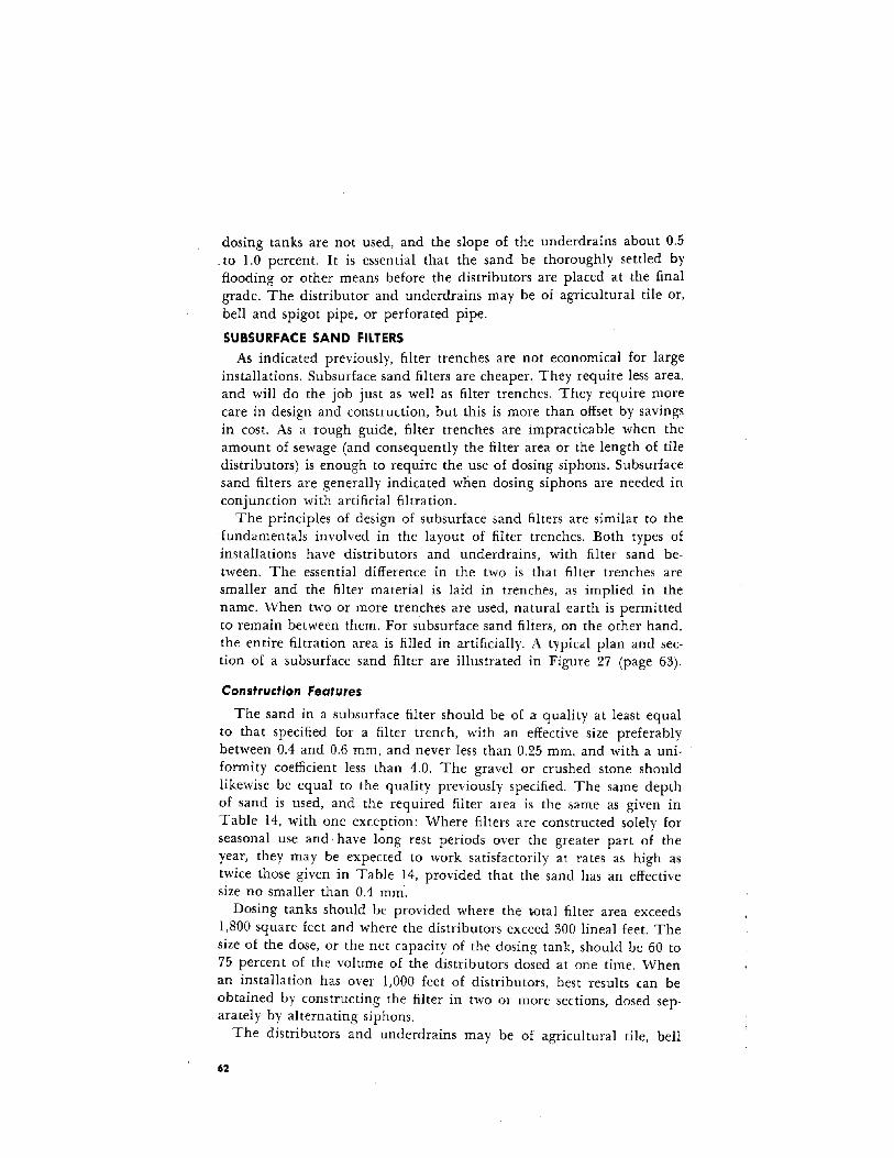
dosing tanks are not used, and the slope of the underdrains about 0.5_to LO percent. It is essential that the sand be thoroughly settled byflooding or other means before the distributors are placed at the finalgrade. The distributor and underdrains may be of agricultural tile or,bell and spigot pipe, or perforated pipe.
SUBSURFACE SAND FILTERS
As indicated previously, filter trenches are not economical for largeinstallations. Subsurface sand filters are cheaper. They require less area,and will do the job just as well as filter trenches. They require morecare in design and construction, but this is more than offset by savingsin cost. As a rough guide, filter trenches are impracticable when theamount of sewage (and consequently the filter area or the length of tiledistributors) is enough to require the use of dosing siphons. Subsurfacesand filters are generally indicated when dosing siphons are needed inconjunction with artificial filtration.
The principles of design of subsurface sand filters are similar to thefundamentals involved in the layout of filter trenches. Both types ofinstallations have distributors and underdrains, with filter sand between. The essential difference in the two is that filter trenches aresmaller and the filter material is laid in trenches, as implied in thename. When two or more trenches are used, natural earth is permittedto remain between them. For subsurface sand filters, on the other hand,the entire filtration area is filled in artificially. A typical plan and section of a subsurface sand filter are illustrated in Figure 27 (page 63).
Construction Features
The sand in a subsurface filter should be of a quality at least equalto that specified for a filter trench, with an effective size preferablybetween 0.4 and 0.6 mm, and never less than 0.25 mm, and with a uniformity coefficient less than 4.0. The gravel or crushed stone shouldlikewise be equal to the quality previously specified. The same depthof sand is used, and the required filter area is the same as given inTable 14, with one exception: Where filters are constructed solely forseasonal use and have long rest periods over the greater part of theyear, they may be expected to work satisfactorily at rates as high astwice those given in Table 14, provided that the sand has an effectivesize no smaller than 0.4 mm-.
Dosing tanks should be provided where the lrotal filter area exceeds1,800 square feet and where the distributors exceed 300 lineal feet. Thesize of the dose, or the net capacity of the dosing tank, should be 60 to75 percent of the volume of the distributors dosed at one time. Whenan installation has over 1,000 feet of distributors, best results can beobtained by constructing the filter in two or more sections, dosed separately by alternating siphons.
The distributors and underdrains may be of agricultural tile, bell
62
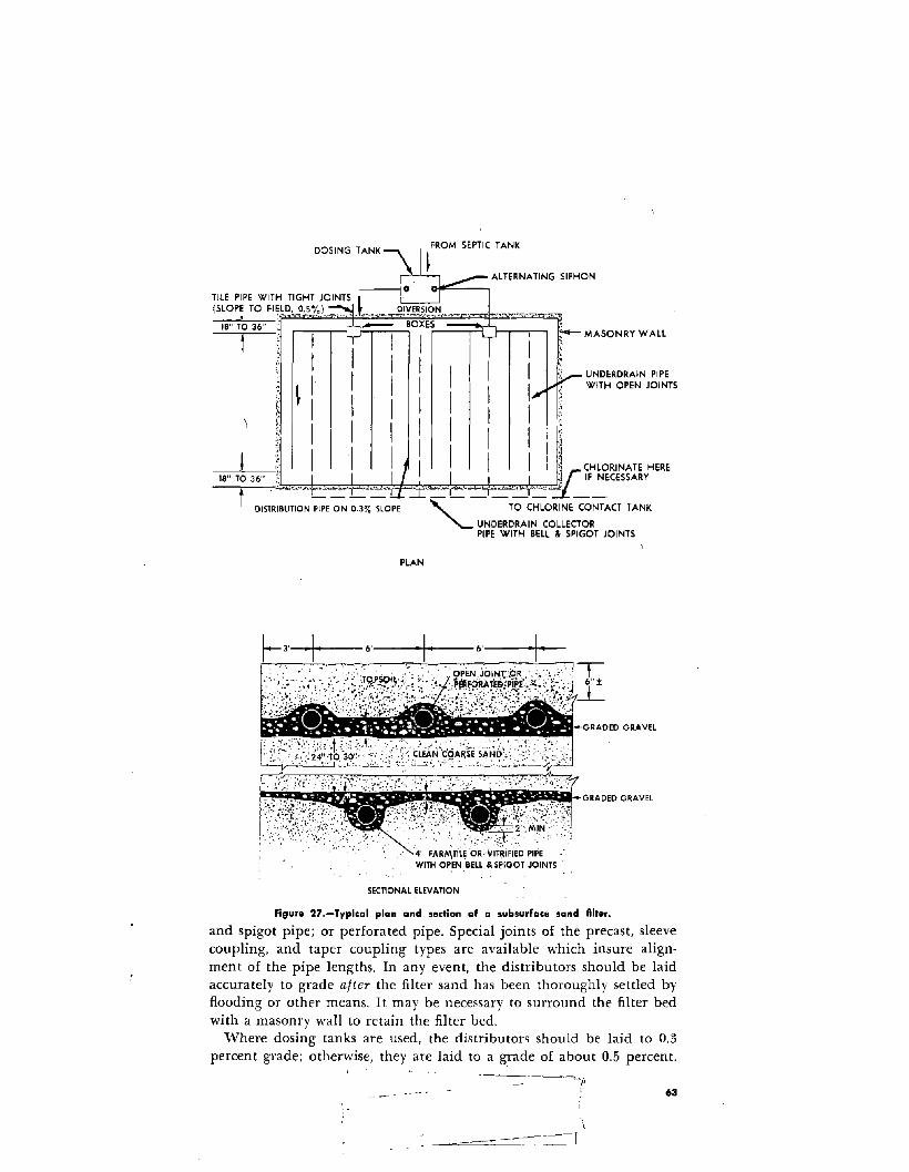
UNDERDRAIN PIPEWITH OPEN JOINTS
DOSING TANK
r;. ALTERNATING SIPHON
~~i~~POW~~~L6~.~~J/I:,~S .L ._ ~IY!R.~I,~~ ...~-- ..~~ ,,_ ''''~>~'r=-~IB" TO 36" ;: _ BOXES .,~t I r MASONRY WALL
I ~
III
I ,~ I I I I ~------l..--" I', ,~ CHLORINATE HERE
T'=L~"#.~_ .:....:-::=., ~...:L'"".-::'c::. ~r""::'''':::::'''':'~ IF':CESSARY
DISTRIBUTION PIPE ON 0.3% SLOPE" TO CHLORINE CONTACT TANK
"- UNDERDRAIN COLLECTORPIPE WITH BELL & SPIGOT JOINTS
PLAN
r- 3,--1f---.6·-----+--·1·-6'-+-
GRADED GRAVEL
SlCl!ill!ll!llli!t;II-GRADED GRAVEL
<.: ,,.ftY~f·~'~{~~~~::'4" FARMTii~'6~\';;~iFI~DPI~E .WITH OPEN ·BELl & S~IGOT JOINTS
SECTIONAL ELEVATION
Figure 27.-Typical plan and sectian af a subsurface sand fllter.
and spigot pipe; or perforated pipe. Special joints of the precast, sleevecoupling, and taper coupling types are available which insure alignment of the pipe lengths. In any event, the distributors should be laidaccurately to grade after the filter sand has been thoroughly settled byflooding or other means. It may be necessary to surround the filter bedwith a masonry wall to retain the filter bed.
Where dosing tanks are used, the distributors should be laid to 0.3percent grade; otherwise, they are laid to a grade of about 0.5 percent.
63
l__I
SUPERFICIAL SAND FILTERS
In some areas, the ground water table is too near the surface to permit construction or successful operation of any subsurface method ofsewage disposal. The construction of buildings and sewage disposalsystems should generally be avoided in such places. Sometimes, however, the elevation of the water table may be found to fluctuate overa wide range unexpectedly. Through floods or other hydrologic conditions, areas which, for decades, may have. experienced a water tableappreciably below the ground surface may suddenly be faced with acondition wherein the ground water approaches or even covers the surface. Sometimes such occurrences are brought about artificially, as bythe construction of dams or dikes, and the conditions may be likely toremain relatively permanent.
As previously explained, impervious soil may also preclude subsurfacemethods of disposal, and the occurrence of solid rock at or just belowthe surface of the ground may make subsurface treatment methodsuneconomical.
In these events, it may be necessary to forego completely the construction or renovation of subsurface methods of sewage treatment anddisposal. The circumstances may require treatment and disposal bysuperficial means above the surface of the ground. This frequentlynecessitates pumping, but can be accomplished in superficial sand filtersconstructed as shown in Figure 28 (page 65), except that the ends andsides must be surrounded by a masonry wall or earth dike for retainingthe filter bed. The filters may be completely above the ground or onlypartly above the surface, depending primarily upon the depth to
ground water or the depth to solid rock, as the case may be.From the standpoint of operation, sewage filters do not have to be
covered, but in built-up areas a shallow earth cover of about 6 inchesis recommended, to prevent freezing in cold weather and to preventemanation of odors and other nuisances from the septic sewage in warmweather. "Vhile open filters are accessible for cleaning and can beoperated at higher rates than those covered with earth, they ordinarilyrequire daily attention, and are not usually advisable for private i~stal
lations where septic tanks are used. They are more suitable for municipalities and large institutions where sewage plant operators are employed. In such cases, the filters generally follow a conventional primary settling tank or secondary treatment and secondary settling tanks,and the method of distributing sewage onto open filters is differentfrom that indicated for covered filters. Figure 28 (page 65) illustrates atypical installation of open filter beds.
Open filters are operated intermittently and, thus, are known asintermittent sand filters. They should always be divided into two ormore units. Sand specifications and depths are the same as for subsurface sand filters. Loading rates are influenced by temperature, effectivesize and uniformity coefficient of the filtering medium, and the charac-
64

A-.,+-- LI II '--tr L2 SLOPE CUT--"1_ ----1,- ---0,1- :::..:.:.JI_--,I I'llI II--
II a. II I II' ~. _.:.:'1__"...- CONCRETE SPLASHII ~', II U /,w. WITH ROUGH TOPI '" II \CAST.,RON IL; / II j FINISHI ,'~ PIPE )r' II i.
~_-.!1, /,11 II ~II' I";~ II II
~TS. ='=,~===;-;===;=== TO DISPOSAL-,I II _ II 11
tW
!~ PLAN, TYPICAL FILTER BED WITH INFLUENT
I CONTROL VALVESJ'.......-::1l PIPE BELOW LEVEL OF FILTER SANDIN C.1. PIPE LINE "tF"'=H INOT TO SCALE I
FI.L~E~ J~~'!,;~~.AV~lc.OR, C.R.\I~I::i~C'!l-?SK, .•,k:~MASONRY RETAINING WAll.'·,;:lr;l.:S:~'., '.' ,.':. ,.'" :" -:: '"",, .' '-. ,. \~IALL AROUND} WITH DIVIDING
J'.~:: ,~>J~~",,: j;-... , .1.- J..i,~~---.,' .:L:_~~&~~--- ',. ~'~'=:~ ~ ~_~j~~;~:,:~~ALL TO SEPARATE BEDS, . - .. '.• " ....... "'.'''' SLOPE BonOM OF CUT
TYPICAL SECTION AT A-A TOWARD DRAIN LINES AS SHOWNI NOT TO SCALE,
TIGHT JOINTS IN ALL TILE L1N,e.~_O_~I_9!.-B,~~~= __= =-r, r-"""- ;:::::=:=:::.~TOOISPOSAL
TILE LINES WITHOPEN JOINTS
PLAN
TYPICAL FILTER BED WITH INFLUENTPIPE ABOVE LEVEL OF FILTER SAND,(NOT TO SCALE,
A
......~~/C.1PIPE
SUPPORTt ',I \J, £.1.PIPE I' I l ;-CONCRETE
j SPLASH BLOCK, . - l:, I AVERAGE SIZE" .~. _ ' 4'0",4'0",4" THICK
L~';~~ "'ZT6P:OF:FiLTE~:SAN~' '::>'
---1'!"'" L I --,-r--il.--LL L2 'JI_ II SLOPE I CUT---., 11- 41-
--II IIII IIII PIPE
I
IW
lDRAIN LINES
WITH OPEN JOINTS
(BELOW LEVEL OF FILTER SANDI (ABOVE LEVEL OF FILTER SANDI
DETAIL-TYPICAL DISCHARGE FOR INFLUENT PIPE
Figure 28.-0pen-filter.bed layout.
teristics of the sewage to be treated, The last depends largely.upon thedegree of pretreatment received by the influent to the filter, but, sincethis manual is concerned only with septic tank systems, pretreatmentmay be ruled out of consideration here. ,Table 15 gives recommendedmaximum loading rates for the effluents from septic tanks which donot receive wastes from garbage grinders or automatic washingmachines,
65

Table 15.-RecammendeJ loading rates of septic tank effluents on open sand lilters with
uniformity coefficients not over 4.0
[Gallons per acre per day'J
Effective Size of Sand
Region 0.2mm. 0.3 mm. 0.4mm. 0.5mm. 0.6mm.
Southern U. S.. 100,000 130,000 160,000 180,000 200,000Northern U. S.. 80,000 100,000 120,000 140,000 160.000
1 Multiply rates by 0.83 if garbage grinders are used.
In addition to dosing by siphons or pumps, some open filters aredosed by means of hand operated gates or valves. In some places, it hasbeen customary to dose about once a day. Other plants operate with asmany as 4 doses per filter per day, but some dose at long and irregularintervals of several days. With fine sands, filtration efficiencies are increased by loading twice daily. With coarse sand (0.45 mm and up),efficiencies are increased by loading more frequently than twice a day,but multiple loadings present a problem in obtaining adequate coverage of the bed. Spray nozzles and rotary distributors have been usedwith reasonable success as dosing devices in some small installations,but it has been found necessary to cover the surface of the sand withseveral inches of pea gravel in order to prevent disturbance of thesurface sand.
Dosing tanks should have capacities that will provide for flooding thebeds to depths of 2 to 4 inches. Discharge from the dosing tanks shouldat least equal the flow of the raw sewage.
Since various States have different requirements or policies regardingopen filter installations, the State or local health department shouldalways be consulted before filters of this type are designed.
CHLORINATION
Filter trenches and artificial sand filters that are properly designedand operated will produce an effluent that is clear and sparkling, andthe filtration will remove a high percentage of the bacteria containedin the sewage. Some of the remaining bacteria may still be capable ofproducing disease, however, and the sewage effluent must be disinfectedif it is discharged to a ditch that is accessible to humans, or to a streamthat contributes to a nearby source of water supply used for drinking,growing of shellfish, or swimming. Chlorine is the disinfectan t mos tcommonly used.
Present custom is to apply chlorine in the amount necessary to obtaina chlorine residual of 0.5 to 1.0 ppm after thorough mixing and 15
66

minutes contact at peak flows. On an average, this requires a chlorinedosage in the neighborhood of 6 ppm for sand filter effluents. This isequivalent to 0! pound of available chlorine for every 10,000 gallonsof sewage, or less than 1 ounce per 1,000 gallons. Most States requirea chlorine contact chamber large enough to retain the sewage for atleast 15 minutes. A typical design is illustrated in Figure 29 (page 68).
Chlorine may be obtained in steel cylinders in which the gas is compressed to a liquid state. It may also be obtained from sodium hypochlorite or calcium hypochlorite.
Sodium hypochlorite is obtainable only as a solution. Upon drying,it decomposes. Solutions of hypochlorite are obtainable in strengthsranging from 1 percent to 15 percent of available chlorine. This material is corrosive to ordinary metals and should be handled in glass,stoneware crocks or plastic containers.
Calcium hypochlorite is obtainable only in a dry form, of whichthere are two principal types. Hypochlorite of lime (or "bleachingpowder") contains about 35 percent of available chlorine when manufactured, and high-test hypochlorite contains about 70 percent ofavailable chlorine.
The ordinary hypochlorite of lime is really a mixture of compoundswhich may be largely a calcium oxychloride. It is not stable, and maylose a large percentage of its chlorine content if stored for long periods.When made into a water solution, it also has the undesirable characteristic of forming a scale of calcium carbonate which tends to clog thefeeding apparatus. It is cheaper than high-test hypochlorite, however,and it can be used satisfactorily with certain types of feeding equipment, if large solution tanks are employed and if proper precautionsare taken in the preparation and utilization of the solution. The undissolved portion must be allowed to settle out of the solution, and onlythe clear, supernatant liquid fed through the feeding apparatus.
High-test hypochlorite is a true calcium hypochlorite. It is morestable and more convenient to handle than ordinary hypochlorite oflime. It is available under several trade names, familiar to sanitaryengineers and sanitarians. When made up with soft water in solutionscontaining 1 to 2 percent of available chlorine, calcium hypochloritedoes not give much trouble with calcium carbonate deposits, but precaution should still be taken to feed only the clear, supernatant portion of the solution through the feeding equipment. When hard wateris used to make up the solution, the addition of a small quantity ofsodium hexametaphosphate will help prevent deposits.
The decision between sodium hypochlorite or calcium hypochloriteshould depend upon the relative costs of the two materials in the locality of the job. Information as to their costs can usually be obtainedfrom the suppliers of the hypochlorinators.
The decision as to whether to apply chlorine as a gas or in liquidform as a hypochlorite is sometimes dependent on the availability of
67

"fk'_~~~DR"".','l"-",'_~,~_.'..' .211_-.~ , __
o--.,__11._.
c.,..._-_.-,-,-,-,._'"'"""I.,Jo."",....,-.-,-,-,-l~--,1--"""":~7' __ _~.,---_--..J-",---'---~~---·~-~AEIN::.EDCONCRETE
"-. WOODEN SAFFLES J"'"""
.... \",.~ , ~ , .~
POINT OF APPLICA •nON OF CHlORINl\ ~
SECTION
Figure 29.-Chlorine-contact chamber.
power. Most manufactured hypochlorinators require either electric current or clean water under pressure for their operation. In some remoteplaces, these are not available. In such cases, hypochlorinators usingchlorine in cylinders can be operated without any outside power source.
Usually, however, power is available and the decision as to whetherto use hypochlorite or chlorine gas is dependent upon their relative cost.Gas is the cheaper of the two, but equipment for controlling it is muchmore expensive than simple hypochlorite feeders,
In general, hypochlorite is preferred when the amount of chlorinerequired is less than 2 or 3 pounds per day. In other words,hypochlorite would normally be used for disinfecting the effluent from a sandsewage filter for sewage flows up to about 50,000 gallons per day, Forchlorinating a septic tank effluent, the sewage flow limit for hypochlorinators would be about 10,000 gallons per day. Beyond these quantities,savings in the cost of the chlorine gas will usually offset the moreexpensive original investment in equipment.
Several satisfactory types of hypochlorinators are available. Varioustypes of chlorinators are also made. Both kinds of apparatus are beinggradually improved. Both require routine maintenance, Therefore, inchoosing the make of apparatus to be purchased, the first considerationshould be that of service. It is practically always advisable to purchasea chlorinator from a manufacturer who has a full time serviceman traveling through the area where it is to be used. Jobbers and agents handling chlorinators are seldom qualified to furnish the best technicalassistance, and are usually unable to render the prompt service that isnecessary when a chlorinator gets out of order.
,l.--'
68

Wherever chlorination ,is necessary, daily tests should be made todetermine the amount of chlorine residual after the requisite contactperiod. Many health departments require monthly reports giving theresults of the tests.
The test is simple. It is usually made by adding a small amount ofstandard orthotolidine solution to a sample of the effluent and comparing the color developed with color standards which may be obtainedwith the solution from most laboratory supply houses. If the color ofthe sample changes to an orange-yellow hue, it indicates that chlorineis being applied in a proper amount.
69

#', ,

Appendices
Introduction To Appendices
Since conditions vary in different parts of the country, practices thatare suitable in one section may not be acceptable in another. Thus, itwould not be feasible to suggest one set of standards that should befollowed in all circumstances. In a sense, this may be considered fortunate, as, to paraphrase Sedgwick, "Standards are devices to keep thelazy mind from thinking." In public health work there can be no substitute for the use of judgment or discretion, more aptly termed byPhelps as an exercise of "the principle of expediency."
Just as no individual design of a sewage disposal system is applicablefor universal adoption because of varying local conditions, so also nosingle ordinance or code would be universally applicable. Though someStates and many local health departments have laws or regulationsgoverning the installation of individual sewage disposal systems, thereis still a growing need for reasonable regulations which will protect thepublic from unsound practices leading to health hazards. The suggestedordinance governing individual sewage disposal systems presented inthese appendices may be useful as a guide in the development of new,or the revision of existing, regulations on this subject.
The purpose of these appendices, therefore, is to discuss additionalpractices which have been found successful in some parts of the country, although their application may be necessarily limited in other parts,and also to present some additional information considered useful toworkers in this field.
71
Appendix A
Soil Absorption Capacity
GUIDE FOR ESTIMATING SOIL ABSORPTION POTENTIAL
A percolation test is the only known means for obtaining a quantitative appraisal of soil absorption capacity. However, observation andevaluation of soil characteristics Iprovide useful clues to the relativecapacity of a soil to absorb liquid. l\lost suitable and unsuitable soilscan be iden'tified without additi'onal testing. '''''hen determined andevaluated by trained or experienced soil scientists or soil engineers, soilcharacteristics may permit further, categorizing of suitable soils. Thishas been done for some areas of, the coun try and described in the soilsreports mentioned below.
Soil Maps.-The capacity of a soil to absorb and transmit water is animportant problem in agriculture, particularly in relation to irrigation,drainage, and other land management practices. Through studies inthese fields, a variety of aids have been develop'eel for judging theabsorption of water transmission properties of soils, which' could behelpful in the sewage field. Considedble information has been accumulated by agricultural authorities on the relative absorption capacitiesof specific soils in many areas qf the United States. !VIuch of this information is included in Soil SUf'>ey Reports and Maps published by theUnited States Department of Agriculture in cooperation with the various State agricultural colleges. The general suitability of specific soilsfor effluent disposal may often be interpreted from these reports andmaps.
Clues to Absorption Capacity.-Considerable information about relative absorption capacities of soils may also be obtained by a close visualinspection of .the soil. The value of such an inspection depends uponsome knowledge of the pertinent soil properties. The main propertiesindicative of absorption capacity are soil texture, structure, color, depthor thitkpess.of permeable strata, and' swelling characteristics.
Textur~.~Soil'texture, the relative proportion of sand, silt, and clay,is the 'most"common clue to ',vater absorption capacity. The size anddistribution of particles govern the size and distribution of pores which,in turn, govern the absorption capacity. The larger the soil particles,the larger are the pores and the faster is the rate of absorption.
Texture can best be judged by the feel. The lighter or sandier soils
72

have a gritty feel when rubbed between the thumb and forefinger; siltytype soils have a "floury" feel and, when wetted ha\'e no cohesion;heavier, clay type soils are dense and hard when dry, and have a slickgreasy feel when wetted.
The use of texture as a clue to absorption qualities has its limita·tions; it is primarily reliable in the sandier soils. In the heavier typesoils, including sandy soils containing appreciable amounts of silt orclay, one must look for additional clues, such as structure and soilcolor, as indicators of absorption capacity.
Structure.---Boil structure is characterized by the aggregation orgrouping together of textural particles, forming secondary particles oflarger size. Such secondary particles then tend to govern the size anddistribution of pores and, in turn, the absorption properties. Structurecan easily be recognized by the manner in which a clod or lump breaksapart. If a soil has structure, a clod will break with very little force,along well defined cleavage planes, into uniformly sized and shapedunits. If a soil has no structure, a clod will require more force to breakapart and will do so along irregular surfaces, with no uniformity' insize and shape of particles.
In general, there are four fundamental structure types, named according to the shape of the aggregate particles: platy, prism-like, block-like.and spheroidal. A soil without structure is generally referred to asmassive. Spheroidal structure tends to provide the most favorable abosorption properties, and platy structure, the least. Although other factors, such as size and stability of aggregates to water, also influence theabsorption capacity, recognition of the type of structure is probablysufficient for a general appraisal.
Color.-One of the most important practical clues to water absorption is soil color. l'>'1ost soils can tain some iron compounds. This iron,
" like iron in a tool or piece of machinery, if alternately exposed to airand to water, oxidizes and takes on a reddish-brown to yellow color.Thus, if a soil has uniform reddish-brown to yellow oxidized color. itindicates that there has been free alternate movement of air and waterin and "through the soil. Such a soil has desirable absorption characteristics. At the other extreme are soils of a dull gray or mottled coloring,indicating lack of oxidizing conditions or very restricted movement ofair and wa ter. These soils have poor absorption characteristics.
Depth or Thickness of Permeable Strata.-The quantity of water thatmay be absorbed is proportional to the thickness or volume of theabsorbent stratum, when all other conditions are alike. In a soil havinga foot or more of permeable material above tig'ht clay, absorption ca·pacityis far greater than that of the same kind of material lying within3 inches of tight clay. 'When examining soils or studying soil descrip:tions, the depth and thickness, therefore, are important criteria ofabsorption capacity. :~
Swelling Characteristics.-Most, but nqi,~, all, clays swell upon the
73

addition of moisture. There are many clays (in the tropics, in particular) that do not swell appreciably. There are also some soils in theUnited States which do not swell noticeably. On the other hand, somesoils have a very hi'gh percentage of swelling, and these in particularmust be suspect. Relative swelling of different soils is indicated by relative shrinkage when dry, as shown by the numbers and sizes of cracksthat form. Those that shrink appreciably when dry are soils that maygive trouble in a tile field when they are wet.
Information obtained through inspection or from soil maps and reports can be of particular value in preliminary appraisal of soils forsewage disposal. For instance, in many cases, unsuitable soils may beimmediately ruled out on the basis of such information; in other cases,selection of the best of several sites may be made on the basis of theinspection. Absorption capacity information obtained in this manner isrelative. For quantitative information upon· which to base specificdesign, we still must depend on some direct measurement, such as awater absorption rate as measured by a percolation test.
EVAPOTRANSPIRATION
In tight clay soils, where absorption is very limited, plant transpiration has been employed with some degree of success in aiding in thedisposal of sewage effluent. By placing the tile lines near the top of thetrench, where they are not likely to become clogged with roots, or bylaying the lines practically at ground surface and covering with suitablefill material, use may be made of the action of trees, shrubs, and grassesin the absorption and subsequent release to the atmosphere of appreciable quantities of moisture, through the process of evapotranspiration.
Climate is important. Evapotranspiration increases wth decreasnghumidity and increasing temperature and air turbulence. Length of dayand amount of sunshine are further influencing factors. Consequently,evapotranspiration should be of most benefit to soil absorption systemsin the southern portion of the country, where the growing season islongest. In the extreme North, where the growing season extends onlyfrom May to September, evapotranspiration would be of minimumvalue, but may be useful in summer resort areas.
Because of these variations. and equally great variations in the typesof plants grown in different parts of the country, as well. as the differing transpiration rates in different plants, it would be' hazardous togeneralize in making specific suggestions on design criteria for systemsdependent on evapotranspiration for successful operation.
CURTAIN DRAINS FOR ABSORPTION TRENCH SYSTEMS
Even though proper precautions are taken to ascertain the maximumground water table before the absorption trench method .of sewageeffluent disposal is approved for a given area, instances occur wherethe height of a water table rises above that indicated by past performances and observations. This may lead to failure of the disposal system.
74

It is sometimes possible to rehabilitate such a system by constructingaround the disposal area a curtain drain designed to intercept thesuperficial ground water and carry it away from the area. If the absorption field is on sloping ground, a single drain at the upper end of thearea may be sufficient. vVhere open curtain drains are not feasible, rockfilled trenches above or around the disposal area may sometimes beused. In either case, it is necessary to have a suitable outlet for theground water that is intercepted.
PERCOLATION TEST HOLES
When making percolation tests in some types of soil, it has beenfound that the side walls of test holes have a tendency to cave in orslough off, and settle to the bottom. The condition is most likely to
occur where the earth is initially dry and overnight soaking is necessary.The caving can be prevented, and more accurate results obtained, byplacing in the test hole a wire cylinder surrounded by gravel of thesame size 'that is used in the tile field.
OTHER PERCOLATION TESTS
A Soil Percolation Test for Determining the Capacity of Soils forAbsorption Sewage Effluents, by John E. Kiker, Jr. l
1. Dig a hole about I foot square to the depth at which it is proposedto lay the tile drain.
2. Fill the hole with water and allow the water to seep away. Whenthe water level falls to within 6 or 8 inches of the bottom of the hole,observe the rate at which the water level drops.
3. Continue these observations until the soil is saturated and thewater seeps away at a constant rate. (Keep adding water until the ratebecomes constant.)
4. Compute the time required for the water to drop I inch after thesoil becomes saturated. This is the standard percolation time, t.A Percolation Test for Determining the Capacity of Soils for Absorp
tion Sewage Effluents, by Harvey F. Ludwig, Gordon W. Ludwig, andJohn Stewart.While the previously cited percolation tests include procedures gen
erally familiar to workers in this field, the method proposed by Ludwiget aI., includes an additional step. The field data are further analyzedgraphically to obtain the percolation rate under saturated soil condi·tions. The mathematical evaluation is based on the premise that theratio, time in minutes for the water level to drop I inch, is constantlyincreasing during the progress of the test, but a t a rate of increasewhich is constantly decreasing. This hyperbolic relationship is utilized
minutesto determine the maximum ratio
inchwhich is the saturated
J Reprinted from Subsurface Sewage Disposal, by John E. Kiker, Jr., Bulletin No.23, Florida Engineering and Industrial Experiment Station, 1948.
75

condition under which water would seep away at a constant rate. Adiscussion of this method with illustrations and an example is foundin the following articles: Improved Soil Percolation Test, Harvey F.Ludwig and Gordon W. Ludwig, Water and Sewage Works Journal,vol. 96, no. 5, May 1949, p. 192; Equilibrium Percolation Test for Estimating Soil Leaching Capacity, Harvey F. Ludwig and John Stewart,Modern Sanitation, vol. 4, no. 10, Oct. 1952.
76
Appendix B
Suggested Ordinance
The following is suggested for consideration in drafting an ordinancefor local application to pennit the exercise of appropriate legal controls over individual sewage disposal systems. l Persons utilizing thisdraft as a guide are urged to familiarize themselves with the applicablelegal requirements governing adoption of ordinances of this kind intheir locality.
AN ORDINANCE GOVERNING INDIVIDUAL SEWAGE DISPOSAL SYSTEMS
An ordinance defining and regulating individual sewage disposalsystems; requiring minimum standards governing the design, construction, and installation of septic tank-soil absorption systems, privies, andchemical-type toilets; authorizing the issuance of permits, and providingfor penalties for violations.
Section I-DefinitionsFor the purposes of this ordinance, the following words and phrases
shall have the meanings ascribed to them in this section.1.1.1 Health officer shall mean the legally designated health au
thority of the (name of political subdivision) or his authorizedrepresentative..
1.1.2 Individual sewage disposal system shall mean a sewage disposal system, other than a public or community system, whichreceives either human excreta or liquid waste, or both, fromone premises. Included within the scope of. this definition areseptic tank-soil absorption systems, privies, and chemical typetoilets, and such other types as may be prescribed in regulations by the health officer.
1.1.3 Permit shall mean a written permit issued by the healthofficer, permitting the construction of an individual sewagedisposal system under this ordinance. .
1.1.4 Person shall mean any institution, p~blic or private COl"PO
ration, individual, partnership, or other entity.
1 Reference should also be made to Recommended State Legislation and Regulations: Urban Water Supply and Sewerage Systems Act and Regulations, Water WellConstruction and Pump Installation Act and Regulations, Individu~l Sewemge Disp.osal Systems Act and Regulations, U.S.D.H.E.W., Public Health Service, July 1965.
77

Section II-Requirements for Individual Sewage Disposal Systems
2.1 The health officer of (name of political subdivision), in order to
protect the health and safety of the people of (name of political subdivision) and of the general public, is authorized and directed, afterpublic hearing, to promulgate and amend, from time to time, regulations establishing minimum standards governing the design, construction, installation, and operation of individual sewage disposal systems.Such regulations shall establish such minimum standards as, in thejudgment of the health officer, will insure that the wastes dischargedto various individual sewage disposal systems:
1. Do not contaminate any drinking water supply.2. Are not accessible to insects, rodents, or other possible carriers
of disease which may come into contact with food or drinkingwater.
3. Do not pollute or contaminate the waters of any bathing beach,shellfish breeding grounds,2 or stream used for public or domestic water supply purposes or for recreational purposes.
4. Are not a health hazard by being accessible to children.5. Do not give rise to a nuisance due to odor or unsightly appear
ance.6. Will not violate any other laws or regulations governing water
pollution or sewage disposal.2.2 The health officer is authorized to promulgate such additional regulations as are necessary in his judgment to carry out the provisions ofthis ordinance.
Section III-Permits
3.1 It shall be unlawful for any person to construct, alter, or extendindividual sewage disposal systems within the (name of political subdivision) unless he holds a valid permit 3 issued by the health officerin the name of such person for the specific construction, alteration, orextension proposed.3.2 All applications for permits shall be made to the health officer, whoshall issue a permit upon compliance by the applicant wilh provisionsof this ordinance and any regulations adopted hereunder.3.3 The health officer may refuse to grant a permit for the constructionof an individual sewage disposal system where public or communitysewerage systems are reasonably available.3.4 Applications for permits shall be in writing, shall be signed by theapplicant, and shall include the following:
3.4.1 Name and address of the applicant.Lot and block number of property on which construction,alteration, or extension is proposed.
2 Optional with locality.3 The permit issued by the Health Officer is in addition to the building permit
usually required and should be obtained prior to construction, alteration, andextension of the residence or facility to be served.
78
3.4.2 Complete plan of the proposed disposal facility, with substantiating data, if necessary, attesting to its compliance withthe minimum standards of the health officer.
3.4.3 Such further information as may be required' by the healthofficer to substantiate that the proposed construction, alteration, or extension complies with regulations promulgated bythe health officer.
3.5 A complete plan for the purpose of obtaining a permit to be issuedby the health officer shall include:
3.5.1 The number, location, and size of all sewage disposal facilities to be constructed, altered, or extended.
3.5.2 The location of water supplies, water supply piping, existingsewage disposal facilities, buildings or dwellings, and adjacent lot lines.
3.5.3 Plans of the proposed sewage disposal facilities to be con-structed, altered, or extended.
3.6 Any person whose application for a permit under this ordinancehas been denied may request and shall be granted a hearing on thematter before the health officer within 30 days after receipt of therequest.
Section IV-Inspections
4.1 The health officer is hereby authorized and directed to make suchinspections as are necessary to determine satisfactory compliance withthis ordinance and regulations promulgated hereunder.4.2 It shall be the duty of the owner or occupant of a property to givethe health officer free access to the property at reasonable times forthe purpose of making such inspections as are necessary to determinecompliance with the requirements of this ordinance and regulationspromulgated hereunder.
Section V-Penalties5.1 Any person who violates any provlSlon of this ordinance, or anyprovision of any regulation adopted by the health officer pursuant toauthority granted by this ordinance. shall, upon conviction, be punishedby a fine of not less than dollars nor more than _dollars, or by imprisonment for not less than__days nor more than__days; and each day's failure to comply shall constitute a separateviolation.
Section VI-Conflict of Ordinances, Effect on Partial Invalidity
6.1 In any case where a provision of this ordinance is found to be in. conflict with a provision of any zoning, building, fire, safety, or healthordinance or code of this (name of political subdivision) existing onthe effective date of this ordinance, the provision which, in the judgment of the health officer, establishes the higher standard for the promotion and protection of the health and safety of the people shallprevail. In any case where a provision of this ordinance is found to be
79

III conflict with a provlSlon of any other ordinance or code of the(name of political subdivision) existing on the effective date of thisordinance which establishes a lower standard for the promotion andprotection of the health and safety of the people, the provisions of thisordinance shall be deemed to prevail, and such other ordinance orcodes are hereby declared to be repealed to the extent that they maybe found in conflict with this ordinance.6.2 If any section, subsection, paragraphs, sentence, clause, or phrase
I of this ordinance should be declared invalid for any reason whatsoever,such decision shall not affect the remaining portions of this ordinance,which shall remain in full force and effect; and, to this end, the provisions of this 'ordinance are hereby declared to be severable.
Section VII-Effective Date7.1 This ordinance shall be effective on and after the dayo~ ,19_.
80
Appendix C
Engineering Information Forms
The pertinent information needed on individual sewage disposalsystems prior to approval by the health or other agency having jurisdiction is outlined in Appendix B. In those instances where subdivisiondevelopments are involved, considerably more data are needed by thehealth agency prior to approval of water and sewage service facilities.The possibility of providing connections to existing municipal systemsor the construction of community water and sewage systems should receive first consideration. In the extreme situation where this is notpossible, and when subsoil conditions are favorable, information of thetype called for in the following "Statement of Information" has beenfound satisfactory in one State. Unless real estate developments in nonsewered areas are properly planned and designed under competentsanitary engineering supervision, public health hazards and nuisancesmay result, with attendant economic loss to the community.
STATE DEPARTMENT OF HEALTH
Statement of Information
Regarding Water and Sewerage Service for Realty Subdivisions
To the State Commissioner Health 19 _Sir:
As required by the provisions of section __ of Article .__ of thePublic Health Law, the following statement is made and submitted withthe plat of a proposed realty subdivision in
(State)
General Information1. Name of subdivision _2. Owner
(State name of person, company. corporation, or association owningthe subdivision)
3. Business address4. Officers
(If organized. give names of officers)
5. Location(Give name of incorporated village or town in which subdivision
is located)6. Area of subdivision Number of lots. '--
(Total size in acres)
81

Families accommodated~ _7. Do you intend to build houses on this subdivision? _
Do you intend to sell lots only? _Do you intend to build on some lots and sell others without
buildings? _
8. Is this subdivision or any part thereof located in an area underthe control of local planning, zoning, or other officials? _
If so, have these plans been submitted to such authorities? _Have these plans been approved or disapproved by such governing
authority? _9. Nature of soil _
(Describe to a depth of 10 feet if tile fields are to be used
for sewage disposal, or 20 feet if leaching pits are proposed, giving thickness
of various strata, such as top soil, clay, loam, sand, gravel, rock, etc,)10. Topography .
(State whether ground is flat, rolling, steep, or gentle slope, etc.)
11. Relative elevation of water table below ground surface _(Give maximum
and minimum, if there is any variation)
Water Service
12. Proposed method of supplying water(Describe in detail, giving name of
municipality, water district or company, if a public water supply is to be used.)
13. State approximate distance to nearest public water supply main ofmunicipal system _
(Give name of municipality, water district, or company)
Sewerage Service
14. Proposed method of collection and disposal of sewage _(Give name of
municipality or sewer district, if public sewers are to be used)
15. State approximate distance to nearest public sewer main of munici-pal system _
Storm Water Drainage
16. State proposed method, if any, of disposing of surface water fromstreets, roofs, land, and other areas
-------_._-----------------------
82

Subdivision Owners Who Intend to Build Homes Must Submit theFollowing Additional Information:
Additional Information:
17. Cellar drainage: Are cellar or footing drains to be installed? _If so, how will drainage be disposed of? _
18. Laundry wastes: Are laundry tubs to be located in basement?__If so, how will wastes be disposed of? _It is hereby agreed that if the attached plans dated _or any amendment or revision thereof, are approved by the StateDepartment of Health, installation of water supply and sewagedisposal facilities will be made in accordance with the detailsthereof as shown on such approved plans. If the subdivided landsshown on such plans are sold before such installations are made, itis agreed that reference to said plans will be made in the deed orcontract of sale, and a covenant inserted therein requiring thepurchaser to install such facilities in accordance wi th such approved plans.
SignatureOfficial ti tIeThis statement must be signed by the owner of the land plattedfor subdivision or the resJXlnsible official of the company orcorporation offering the same for sale.
Important Note
This form must be accompanied by:(I) One U. S. G. S. topographic map or other general map showing
exact location and approximate boundaries of subdivision.(2) A print on cloth for filing with the State Department of Health,
together with such other tracings and prints (see below) as may benecessary for filing with the county clerk and owner of the subdivision, showing:(a) subdivision layout, including streets, building lines, lot dimen
sions, and other pertinent data;(b) existing and proposed water mains, if available. If public
water supply is available, show existing and proposed watermains for all lots, and submit a copy of the contract betweenthe developer and the waterworks officials, or a letter fromsuch officials stating that an agreement has been reachedregarding the supply of such facilities.
(c) existing an~ proposed sewers; if already approved by Department give date of approval; or, if not approved, applicationmust be made and detailed plans of sewer extensions submitted by officials in charge of sewer systems, in accordancewith section of the Public Health Law.
(d) details of a typical lot arrangement showing general locationof well and septic tank, subsurface absorption devices, etc.
83

(where either or both public water and sewerage service areinaccessible), plus the following:(I) development of well (giving sufficient detail to show how
the well will be developed and protected from pollution,its depth, and strata penetrated).
(2) cross section of soil showing depth of various strata (unlessexplained in detail under item 9).
(3) plan and section of all parts of sewage disposal system,giving all dimensions and grades.
(4) actual field results of soil tests to determine absorptivecapacity of soil (may be submitted with correspondence).
Inasmuch as stamp of approval must be placed on face of plans, aspace 3 by 6 inches should be reserved for this purpose. This spacemust be blocked out in white if blueprints are submitted.
Size of plans for filing with county clerk; 20 by 20 inches or 20 by 40inches, tracing cloth or white prints on cloth.
84
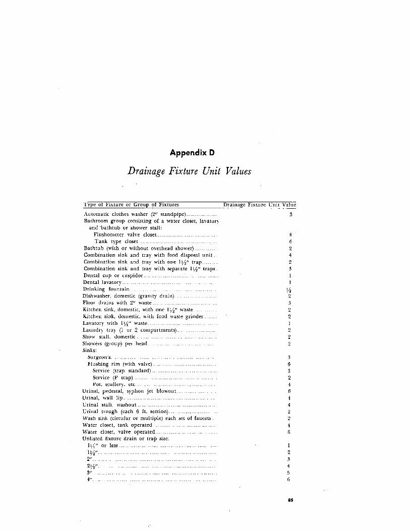
Appendix D
Drainage Fixture Unit Values
Type of Fixture or GTOUp of Fixtures
Automatic clothes washer (2" standpipe) ......Bathroom group consisting of a water closet, lavatory
and 'bathtub or shower stall:Flushometer valve closet.. .......Tank type closet.
Bathtub (with or without overhead shower) ..Combination sink and tray with food disposal unit.. .Combination sink and tray with one IY2" trap ..Combination sink and tray with separate 1Y2" traps ..Dental cup or cuspidor...Dental lavatory ..Drinking fountain ..Dishwasher, domestic (gravity drain).Floor drains with 2" waste ..Kitchen sink, domestic, with one I Y2" waste..Kitchen sink, domestic, with food waste grinder..Lavatory with I \!.I" waste ..Laundry tray (lor 2 compartments) ..Show stall, domestic ..Showers (group) per head ..Sinks:
Surgeon's ..Flushing rim (with valve) ..
Service (trap standard) ..Service (P trap) ..Pot, scullery, etc.. ,.
Urinal, pedestal, syphon jet blowout..Urinal, wall lip ..Urinal stall, washou t .Urinal tTOugh (each 6 ft. section) ..."Vash sink (circular or multiple) each set of faucetsWater closet, tank operated"Vater closet, valve operated.....Unlisted fixture drain or trap size:
I \!.I" or less.
IW'2".2W'.3",4",
Drainage Fixture Unit Value
862423II
Y22322I222
363246
442246
I23456
85

Appendix E
Suggested Specifications for Watertight Concrete
1. MaterialsPortland cement should be free of hard lumps caused by moisture
during storage. Lumps from dry packing that are easily broken in thehand are not objectionable. I
Aggregates, such as sand and gravel, should be obtained from sourcesknown to make good concrete. They should be clean and hard. Particlesize of sand should range very fine to Y4 inch. Gravel or crushed stoneshould have particles from Y4 inch to a maximum of l12 inches in size.Water for mixing should be clean.2. Proportioning
Not more than 6 gallons of total water should be used for each ba'gof cement. Since sand usually holds a considerable amount of water,not more than 5 gallons of water per bag of ,cement should be addedat the mixer when sand is of average dampness. More mixing waterweakens the concrete and makes it less watertight. For average aggregates, the mix proportions shown in the table below will give water·tight concrete.
Average Proportions for Watertight Concrete
Max. Size Cement 'Water' Sand GravelGravel (in.) (volume) (volume) (volume) (volume)
1\12 1 % 20 3
% 1 3,4 2\12 2\12
1 Assuming sand is of average dampness.
3. Mixing and PlacingAll materials should be mixed long enough so that the concrete has
a uniform color. As concrete is deposited in the forms, it should be
1 Type V portland cement may be used when high sulfate resistance is required.
86

tamped and spaded to obtain il dense wall. The entire tank should becast in one continuous operation if possible, to prevent constructionjoints.4. Curing
After it has set, new concrete should be kept moist for at least sevendays to gain strength.
87

Appendix F
Industrial Waste Treatment
Septic tank systems are not employed for the treatment of industrialwastes from large manufacturing industries. In small industrial plants,septic tank systems, assisted as needed by supplementary processes maybe used advantageously either for treating wastes to render them suitable for final disposal by one of the methods described in Part Il, orfor conditioning wastes to render them acceptable for discharge tosewer systems where they would otherwise be objectionable.
It is important to note that the design of septic tank systems fortreatment and disposal of industrial wastes is not sufficiently simple topermit formulation of specific criteria for design. This is because indus·'trial wastes vary widely in their composition; in fact, rarely do any twoplants produce wastes of the same character and composition. Thedesign of an industrial waste treatment and disposal system is, therefore, a problem requiring specialized sanitary engineering consultation,and this consultation usually includes special laboratory analyses andstudies of the particular wastes under consideration. With these precautions, however, it is possible, in many instances, to develop a work·able septic tank system which is actually simple, effective, economical,and within the means of the small industrial plant.
The following is intended to indicate only qualitatively some of themethods applicable to a few industrial wastes. The particular designfor any given waste must be prepared by competent sanitary engineers.
LAUNDRY WASTES AND OTHER GREASY WASTESWastes derived from laundries and some other sources, which contain
soaps, oil, and greases in relatively low concentrations, may be successfully disposed of by one of the methods previously described, providedthe greasy substances are first removed. If greasy substances, includingsoaps and oils, are discharged into absorption systems, they accumulateand soon cause clogging of the soil pores.
The greasy substances contained in wastes are of two types: (1) thefloatable greases, which are nonemulsified and which, therefore, uponquiescence or standing, will separa[e and rise to the surface of theliquid to form a surface layer; and (2) the emulsified greases, whichdo not separate upon standing. Both of these components may bepresent in considerable concentrations, and both must be removed.
88
Properly designed, conventional grease traps, such as those used forrestaurant wastes, will remove floatable grease, but not emulsifiedgrease. Emulsified grease may be removed in a practical manner, however, either (1) by passing the waste through a rock filter, or (2) bychemically flocculating the waste.
Where relatively low concentrations of emulsified grease are present,the rock filter process may be successfully used. The rock filter servesto deemulsify the grease, changing it to floatable grease so that it maybe subsequently removed by simple trapping. Septic tank units may beemployed advantageously both for trapping the floatable grease andto serve as the con tainer for the rock fi 1ter. The servicing required forthis system includes removal of the accumulated floatable grease atregular intervals and occasional replacement of the filter rock. Thesizes of the trap and rock filter units will depend upon the quantity ofthe waste and its composition, as determined by laboratory analyses.
Where high concentrations of emulsified grease are present, a chemical flocculation process may be needed. For all of these processes (trapping, flocculation, and settling), septic tanks may be used as the mosteconomical means of obtaining the necessary capacities. Also required,as accessories to the flocculation process, are a suitable electricallyoperated stirring device and a volumetric type chemical feeder. Maintenance of the system includes keeping the chemical feeder stocked withchemicals and periodic pumping of accumulated sludge from the settling basin. In this process, the grease particles are agglomerated bythe flocculating action into large particles which settle out in thesettling basin. The sizes of the various tanks, the amounts of flocculating chemicals needed, and the frequency of pumping required willdepend upon the quantity of the waste and its composition, as determined by laboratory analyses.
SLAUGHTERHOUSE, DAIRY, AND OTHER ORGANIC WASTES
These wastes are generally characterized by very high concentrationsof organic materials, up to (and even exceeding) 100 times the strengthof ordinary sanitary sewage. Part of the organic m~terial is in truesolution, and this may sometimes be disposed of by simple underground absorption, provided there is adequate area and provided a suitable schedule for resting the absorption areas is maintained. Much ofthe organic material, including the emulsified greases, is in colloidalsuspension. Colloidal particles will clog underground absorption systems. They do not settle out on quiescence and, therefore, have to beremoved by some means, such as by flocculation and sedimentation,or by application to trickling filters followed by settling. As in the preceding example, septic tanks may advantageously be used to providethe necessary tank capacities for the trapping, flocculating. and settling processes.
89

MINERAL OR INORGANIC WASTES
Mineral and similar wastes present special problems generally requiring chemical neutralization or other chemical treatment beforethe wastes may be filtered or absorbed into the ground. Importantfactors are the metallic and nonmetallic ions present, their concentrations, and, for underground absorption the nature and importance ofthe water basin lying below the area intended for absorption. Septictanks can sometimes be used· advantageously in the solution of theseproblems, as chemical reaction chambers, settling tanks, etc.
90
=
Bibliography
Partial List of References on Septic Tank
Soil Absorption Systems
Appendices to Study of Seepage Beds, James B. Coulter; Thomas W. Bendixen; andAllen B. Edwards; Report to the Federal Housing Administration, December 15,1960.
A Basis for Classifying Soil Permeabilities, T. W. Bendixen; M. F. Hershberger; andC. S. Slater; Jour. Agric. Research, v. 77, no. 5; Sept. 1, 1948.
Causes and Prevention of Failure of Septic Tank Percolation Systems, P. H.McGauhey; and John H. \Vinneberger; Federal Housing Administration ReportNo. 533, 1964.
Degradation of ABS and Other Organics in Unsaturated Soils, G. G. Robeck; J. M.Cohen; W. J. Sayers; and R. L. Woodward; Journal of the Water PollutionControl Federation; v. 35; no. 10; Oct. 1963.
Detergents and Septic Tanks, James E. Fuller; Sewage and Ind. Waste, 24, 844;July 1952.
The Effect of Automatic Sequence Clothes Washing Machines on Individual SewageDisposal Systems, NAS Publication 442, Building Research Institute, NationalAcademy of Science, National Research Council, Washington, D.C.
Effects of Food Waste Grinders on Septic Tank Systems, T. W. Bendixen; A. A.McMahan; J. B. Coulter; and R. E. Thomas; Report to the Federal HousingAdministration, Nov. 15, 1961.
Effects of Ground Garbage on Sewage Treatment Processes, 'Villiam Rudolfs;Sewage Works Journal, v. 18, no. 6, p. 1144; Nov. 1946.
Effectiveness of the Distribution Box, J. B. Coulter; and T. ·W. Bendixen; Reportto the Federal Housing Administration, Feb. 19, 1958.
Environmental Sanitation, J. A. Salvato, Jr.; John Wiley & Sons, Inc. 1958.Estimating Soil Moisture Conditions and Time for Irrigation with the Evapo
transpiration Method,. C. H. M. Van Bavel; U. S. Department of AgriculturePublication ARS 41-11, August 1956.
Factors Influencing the Design and Operation of Soil Systems f01- Waste Treatment,G. G. Robeck; T. W. Bendixen; W. A. Schwartz; and R. L. Woodward; Journalof the 'Vater Pollution Control Federation, v. 36, no. 8, Aug. 1964.
Field Investigation of Waste Water Reclamation in Relation to Ground WaterPollution, State Water Pollution Control Board, Publication No.6, State ofCalif., 1953.
Final Report on A Study of Preventing Failure of Septic Tank Percolation Systems,P. H. McGauhey; and J. H. Winneberger; SERL Report No. 65-17, SanitaryEngineering Research Laboratory, University of California. Berkeley, 1965.
Improved Soil Percolation Test, H. F. Ludwig and G. W. Ludwig, Water andSewage Works, v. 96, 5; May 1949.
Individual Sewage Disposal Systems, Recommendations of Joint Committee on Rural
91

Sanitation; Reprint No. 2461 from Public Health Reports. Public HealthService (revised 1947).
Notes Oil the Design of Sewage Disposal Works, with Special Refeunce to SlIwllInstallations, Henry R yon; Albany, N. Y.; 1928.
Progress in the Design Of Rural Sewage Disposal Systems, Am. Jour. Pub. Health.Year Book. Part 2, 1952-53; May 1953.
Septic Tank Care, PHS Publication No. 73, U. S. Department of Health, Education.and '\Telfare, Public Health Service, \\Tashington, D.C,
Septic Tank Drainage Systems, W. H. Sheldon; Research Report No. 10. lvlichiganState University, Agriculture Experiment Station, East Lansing.
Septic Tank Soil A bsorption Systems for Dwellings, Construction Aid No.5,Housing and Home Finance Agency, Division of Housing Research, \'1'ashington25, D. C.
Soils Suitable for Septic Tank Filter Fields, W. H. Bender; U, S, Department ofAgriculture, Agricultural Information Bulletin No. 243. 1961.
Soil Suroey Manual, Agricultural Handbook No. 18. U.S. Department of Agricul·ture, 1951.
Some Factors Which Modify the Rate and Total Amount of Infiltratioll of FieldSoils, G. \\T. Musgrave; and G. R. Free; Jour. Amer. Soc. Agron .. v. 28;727-739; 1936.
Studies on Household Sewage Disposal Systems, Part I, S. R. \\Teibel; C. P. Straub;and 1- R. Thomas; Federal Security Agency, Public Health Service, Environ·mental Health Center, 1949.
Studies on Household Sewage Disposal Systems, Part II, T. W. Bendixen; M. Berk:1- P. Sheehey; and S. R. "Weibel; Federal Security Agency, Public HealthService, Environmental Health Cent<cr, 1950.
Studies on Household Sewage Disposal Systems, Part III, S. R. Weibel; T. W.Bendixen; 1- B. Coulter; U. S. Dept. of Health, Education, and Welfare, PublicHealth Service, Robert A. Taft Sanitary Engineering Center, 1955.
A Study of Methods Of Preventing Failure Of Septic Tank Pel'colation S1'stems,1- H. Winneberger and P. H. 1\IcGauhey, SERL Report No. 65-16, SanitaryEngineering Research Laboratory, University of California. Berkeley. 1965.
Study of Seepage Beds, 1- B. Coulter; T. W. Bendixen; and A. B, Edwards; Reportto the Federal Housing Administration, Dec. 15, 1960.
Study of Seepage Pits, Thomas W. Bendixen; R. E. Thomas; and J .. B. Coulter;Report to the Federal Housing Administration, !llay 1, 1963.
A Studv of Serial Distribution for Soil Absorption Systems, G. M. Sullivan; J. B,Coulter; and T. W. Bendixen; Report to the Federal Housing Administration.April 8, 1959.
Subsurface Sewage Disposal, 1-. E. Kiker, Jr.; Bull. No. 23,' Florida Eng. Ind. Expel'.Station, Univ. of Florida, Dec. 1948.
Tmnspiration and Total Evaporation, Physics of the Ealth, IX, qharles H. Lee.Hydrology; McGraw-Hill Book Co., Inc.; 1942.
Water, The Yearbook of Agriculture, 1955, U. S. Dept. of Agricultme. 84th Cong.,1st Session, House Document No. 32.
1:1 u.s, GOVERNMENT PRINTING OFFICE' 1957-0265-474
92
/