manual lsm – user - simonsvoss · manual lsm – user version: march 2013 v1.6 page 7 1.0...
TRANSCRIPT
MANUAL LSM – USER
Version: March 2013

MANUAL LSM – USER
Version: March 2013 v1.6
Page 2
1.0 Introduction ........................................................................................ 7
Important note.......................................................................................................7
1.1. Understanding this manual .......................................................................7
2.0 Icons.................................................................................................... 9
Standard toolbar .................................................................................................10
Areas / transponder group view ........................................................................11
Doors / Persons view..........................................................................................11
Group authorisation tree view ...........................................................................12
PROGRAMMING REQUIREMENT ......................................................................12
3.0 Setting up and opening the database ............................................ 13
1.0 What is new in lsm 3.2?................................................................... 14
2.0 ViewS and navigating ...................................................................... 15
2.1. Areas / transponder groups view............................................................15 2.1.1 General ........................................................................................................................ 15
2.2. Doors / Persons view ...............................................................................16 2.2.1 General ........................................................................................................................ 16
2.3. NavigATIng ...............................................................................................17
2.4. Configuring standard view ......................................................................19
2.5. Adjusting views ........................................................................................21 2.5.1 Sorting......................................................................................................................... 21 2.5.2 Additional columns in label bars.............................................................................. 22 2.5.3 SWAPPING the view of components in the matrix................................................. 23
3.0 Issuing authorisations ..................................................................... 24
3.1. Show / issue group authorisation ...........................................................24
3.2. Show / issue individual authorisations ..................................................26
4.0 SEARCH ............................................................................................ 27
4.1. SEARCHABLE OBJECTS.........................................................................28 4.1.1 User ............................................................................................................................. 28 4.1.2 User group .................................................................................................................. 28 4.1.3 Area ............................................................................................................................. 28 4.1.4 Public holiday............................................................................................................. 28 4.1.5 Public holiday list....................................................................................................... 28 4.1.6 Building....................................................................................................................... 28
MANUAL LSM – USER
Version: March 2013 v1.6
Page 3
4.1.7 Local time zone .......................................................................................................... 28 4.1.8 Person ......................................................................................................................... 28 4.1.9 Locking system .......................................................................................................... 28 4.1.10 Lock............................................................................................................................. 28 4.1.11 Location ...................................................................................................................... 28 4.1.12 Transponder ............................................................................................................... 28 4.1.13 Transponder group .................................................................................................... 28 4.1.14 Door ............................................................................................................................. 28 4.1.15 Time group.................................................................................................................. 28 4.1.16 Time zone plan ........................................................................................................... 28
5.0 FILTERS ............................................................................................ 29
5.1. General information about filters............................................................29
5.2. Managing / creating filters .......................................................................29
5.3. Managing filters – activating / deactivating ...........................................31
6.0 MANAGING THE LOCKING SYSTEM.............................................. 32
6.1. Locking system ........................................................................................32 6.1.1 General information about the locking system....................................................... 32 6.1.2 Locking system properties ....................................................................................... 35 6.1.3 Creating a locking system......................................................................................... 46 6.1.4 Editing a locking system........................................................................................... 46
6.2. Transponder group ..................................................................................47 6.2.1 General ........................................................................................................................ 47 6.2.2 Creating a transponder group .................................................................................. 47 6.2.3 Editing a transponder group..................................................................................... 48 6.2.4 Management ............................................................................................................... 50 6.2.5 TRANSPONDER ASSIGNMENT ................................................................................ 53
6.3. Transponders ...........................................................................................56 6.3.1 general......................................................................................................................... 56
5.3.2 Transponder properties ...........................................................................58 6.3.2 Editing transponders ................................................................................................. 67
6.4. Persons .....................................................................................................68 6.4.1 General information about persons ......................................................................... 68 6.4.2 Creating a person....................................................................................................... 70 6.4.3 Editing persons .......................................................................................................... 70
6.5. Area ...........................................................................................................72 6.5.1 General information about areas.............................................................................. 72 6.5.2 Creating an area ......................................................................................................... 74 6.5.3 Editing an area ........................................................................................................... 74
MANUAL LSM – USER
Version: March 2013 v1.6
Page 4
6.6. Lock ...........................................................................................................76 6.6.1 General information about locks.............................................................................. 76 6.6.2 Lock properties .......................................................................................................... 78 6.6.3 creating a lock ............................................................................................................ 94 6.6.4 Editing a lock.............................................................................................................. 96
6.7. Doors .........................................................................................................97 6.7.1 General corrections for doors .................................................................................. 97 6.7.2 Edit door...................................................................................................................... 99
6.8. Location ..................................................................................................100 6.8.1 General information about locations ..................................................................... 100 6.8.2 Create location ......................................................................................................... 101 6.8.3 Edit location.............................................................................................................. 101
6.9. 5.9 Building .............................................................................................102 6.9.1 5.9.1 General information about buildings............................................................ 102 6.9.2 5.9.2 Create building ................................................................................................ 103 6.9.3 5.9.3 Edit building .................................................................................................... 103
7.0 Wizards ........................................................................................... 104
7.1. Door wizard.............................................................................................105
7.2. 6.2 Person wizard ...................................................................................113
8.0 Alerts ............................................................................................... 125
8.1. General information about alerts ..........................................................125
8.2. Create alerts............................................................................................126
8.3. Edit alerts ................................................................................................127
8.4. Delete alerts ............................................................................................127
8.5. Alert monitor...........................................................................................128
9.0 Reports............................................................................................ 130
9.1. General information about reports .......................................................130
9.2. Basic settings for reports ......................................................................130
9.3. Select report ...........................................................................................130 8.1.1 Locking system ........................................................................................................ 131 8.3.2 Area ........................................................................................................................... 132 8.1.2 Transponder group .................................................................................................. 133 8.1.3 Door ........................................................................................................................... 134 8.1.4 Lock........................................................................................................................... 135 8.1.5 Transponder ............................................................................................................. 136 8.1.6 Time group................................................................................................................ 137 8.1.7 Time zone plan ......................................................................................................... 138
MANUAL LSM – USER
Version: March 2013 v1.6
Page 5
8.1.8 Network ..................................................................................................................... 139 8.1.9 HR structure ............................................................................................................. 140 8.1.10 Building structure .................................................................................................... 141 8.1.11 User ........................................................................................................................... 142 8.1.12 Various ...................................................................................................................... 143
9.4. Print report..............................................................................................144
9.5. Export report...........................................................................................144
9.6. Reports for assembly preparation ........................................................145
10.0 Programming processes ............................................................... 147
10.1. General ....................................................................................................147
10.2. Position components .............................................................................147
10.3. Program...................................................................................................148 9.3.1 Program lock ............................................................................................................ 148 9.3.2 Program transponder .............................................................................................. 150
10.4. Read.........................................................................................................152 9.4.1 Read lock .................................................................................................................. 152 9.4.2 Read transponder .................................................................................................... 159
10.5. Reset........................................................................................................163 10.5.1 Reset lock ................................................................................................................. 163 10.5.2 Reset transponder ................................................................................................... 163
10.6. Mobile programming..............................................................................164 10.6.1 General ...................................................................................................................... 164 10.6.2 Export ........................................................................................................................ 167 10.6.3 Configure tasks ........................................................................................................ 170 10.6.4 Import ........................................................................................................................ 174
10.7. LSM Mobile .............................................................................................175
11.0 Miscellaneous................................................................................. 177
11.1. Deleting an employee when transponder is returned .........................177
11.2. Deleting an employee when transponder is not returned...................177
11.3. Create replacement transponder ..........................................................177
11.4. Procedure to follow for a defective transponder .................................178
11.5. Procedure to follow for replacing a defective lock..............................179
11.6. Overlay mode..........................................................................................180
11.7. Overall locking levels.............................................................................180 11.7.1. Creating a higher-level locking level...................................................................... 180 11.7.2 Creating a higher ranking transponder ............................................................... 181
MANUAL LSM – USER
Version: March 2013 v1.6
Page 6
4.0 Service and Support ...................................................................... 182
NOTE: In the explanations of the various functions of the system, the focus is on operating the software. Please refer to the individual product manuals for descriptions of the individual product features, fittings and functions. It is important to comply with the product approvals and system requirements when installing and operating the products. SimonsVoss accepts no liability and cannot provide support for installation or operation which deviates from these instructions. SimonsVoss Technologies AG reserves the right to make modifications to the product without notice. Consequently, descriptions and representations in this documentation may vary from the most recent product and software versions. As a general principle, the original German version shall apply in the event of any doubt. Subject to errors and misspellings. These documents are based on the current programme status at the time of printing. The information and data they contain may be changed without advance notice and do not represent an obligation on the part of the seller. The software and hardware designations used in this manual are mainly registered trademarks and as such are subject to the legal copyright protection law regulations. Neither the manual nor extracts of it may be reproduced or disseminated by mechanical or electronic means, photocopying or otherwise without our express written permission. The companies and other pieces of data used in the examples are fictitious, any similarities are therefore purely coincidental. The editors of this LSM manual took great care when compiling this text. However we cannot guarantee that it is free from errors. The LSM editing team is not liable for technical or printing errors in this manual. The descriptions provided in this manual are not of a guaranteed quality in the eyes of the law. Please send any corrections or suggestions for improvement to [email protected]. Thank you in advance for your support. More information about SimonsVoss products can be found online at WWW.SIMONS-VOSS.DE This manual applies to software without functional limitations. Functions or views in a customer’s specific installation may deviate from these due to the software modules activated.
MANUAL LSM – USER
Version: March 2013 v1.6
Page 7
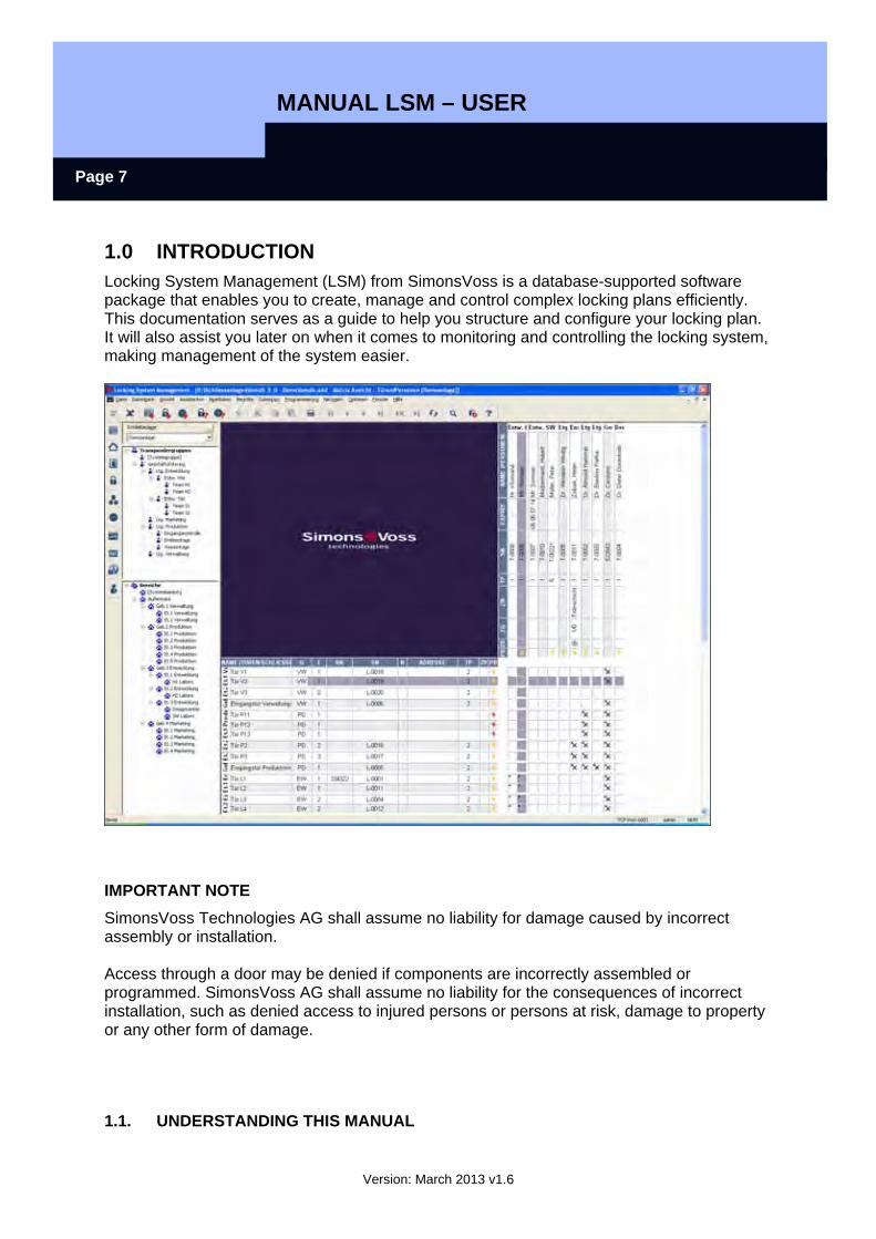
1.0 INTRODUCTION Locking System Management (LSM) from SimonsVoss is a database-supported software package that enables you to create, manage and control complex locking plans efficiently. This documentation serves as a guide to help you structure and configure your locking plan. It will also assist you later on when it comes to monitoring and controlling the locking system, making management of the system easier.
IMPORTANT NOTE SimonsVoss Technologies AG shall assume no liability for damage caused by incorrect assembly or installation. Access through a door may be denied if components are incorrectly assembled or programmed. SimonsVoss AG shall assume no liability for the consequences of incorrect installation, such as denied access to injured persons or persons at risk, damage to property or any other form of damage.
1.1. UNDERSTANDING THIS MANUAL
MANUAL LSM – USER
Version: March 2013 v1.6
Page 8
MENU ITEMS The LSM menu items are indicated in this manual by the symbol.
EXAMPLES Edit Area
HEADINGS AND CHECKBOXES Headings and checkboxes shown in the screenshots are differentiated by the use of inverted commas.
EXAMPLES “User Groups” “Areas”
BUTTONS Buttons shown in the screenshots are highlighted in grey.
EXAMPLES OK Apply
KEY COMBINATIONS The key combination you can use to start the required functions is shown in bold. Ctrl+Shift+X
PATH SPECIFICATIONS If an instruction refers to a directory on a drive, the path is provided in italics.
EXAMPLE C:\Program files\SimonsVoss\LockSysGui\
NOTE The specification [CDROM] is a variable and describes the letter identifying the drive of the CDROM drive on the computer (e.g. “D”) on which installation is to be carried out.
MANUAL LSM – USER
Version: March 2013 v1.6
Page 9
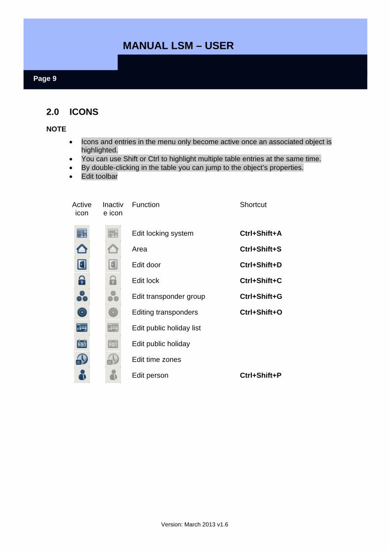
2.0 ICONS
NOTE
• Icons and entries in the menu only become active once an associated object is highlighted.
• You can use Shift or Ctrl to highlight multiple table entries at the same time. • By double-clicking in the table you can jump to the object’s properties. • Edit toolbar
Active icon
Inactive icon
Function Shortcut
Edit locking system Ctrl+Shift+A
Area Ctrl+Shift+S
Edit door Ctrl+Shift+D
Edit lock Ctrl+Shift+C
Edit transponder group Ctrl+Shift+G
Editing transponders Ctrl+Shift+O
Edit public holiday list
Edit public holiday
Edit time zones
Edit person Ctrl+Shift+P
MANUAL LSM – USER
Version: March 2013 v1.6
Page 10
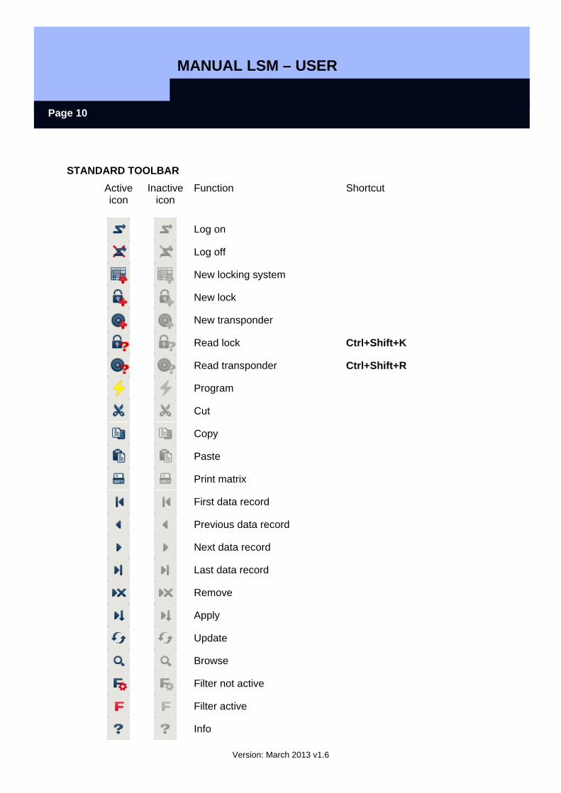
STANDARD TOOLBAR Active icon
Inactive icon
Function Shortcut
Log on
Log off
New locking system
New lock
New transponder
Read lock Ctrl+Shift+K
Read transponder Ctrl+Shift+R
Program
Cut
Copy
Paste
Print matrix
First data record
Previous data record
Next data record
Last data record
Remove
Apply
Update
Browse
Filter not active
Filter active
Info
MANUAL LSM – USER
Version: March 2013 v1.6
Page 11
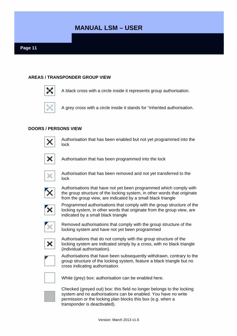
AREAS / TRANSPONDER GROUP VIEW
A black cross with a circle inside it represents group authorisation.
A grey cross with a circle inside it stands for “inherited authorisation.
DOORS / PERSONS VIEW
Authorisation that has been enabled but not yet programmed into the lock
Authorisation that has been programmed into the lock
Authorisation that has been removed and not yet transferred to the lock
Authorisations that have not yet been programmed which comply with the group structure of the locking system, in other words that originate from the group view, are indicated by a small black triangle
Programmed authorisations that comply with the group structure of the locking system, in other words that originate from the group view, are indicated by a small black triangle
Removed authorisations that comply with the group structure of the locking system and have not yet been programmed
Authorisations that do not comply with the group structure of the locking system are indicated simply by a cross, with no black triangle (individual authorisation).
Authorisations that have been subsequently withdrawn, contrary to the group structure of the locking system, feature a black triangle but no cross indicating authorisation.
White (grey) box: authorisation can be enabled here.
Checked (greyed out) box: this field no longer belongs to the locking system and no authorisations can be enabled. You have no write permission or the locking plan blocks this box (e.g. when a transponder is deactivated).

MANUAL LSM – USER
Version: March 2013 v1.6
Page 12
GROUP AUTHORISATION TREE VIEW
Manually enabled (black)
Directly inherited (green)
Indirectly inherited – inherited via subordinate group (blue)
Directly and indirectly inherited (blue / green)
PROGRAMMING REQUIREMENT
EXPLANATION There are various reasons why it may be necessary to program a transponder or lock. The programming lightning symbol is shown in different colours to indicate the different reasons why programming is required.
DISPLAY
Simple programming requirement for components
Transponder: Validity expired Deactivated Lock Only overall locking level assigned Not assigned to any door Not assigned to any locking system Door without lock
Programming requirement on a lock after creating a replacement transponder in the overlay mode of a G1 system
MANUAL LSM – USER
Version: March 2013 v1.6
Page 13
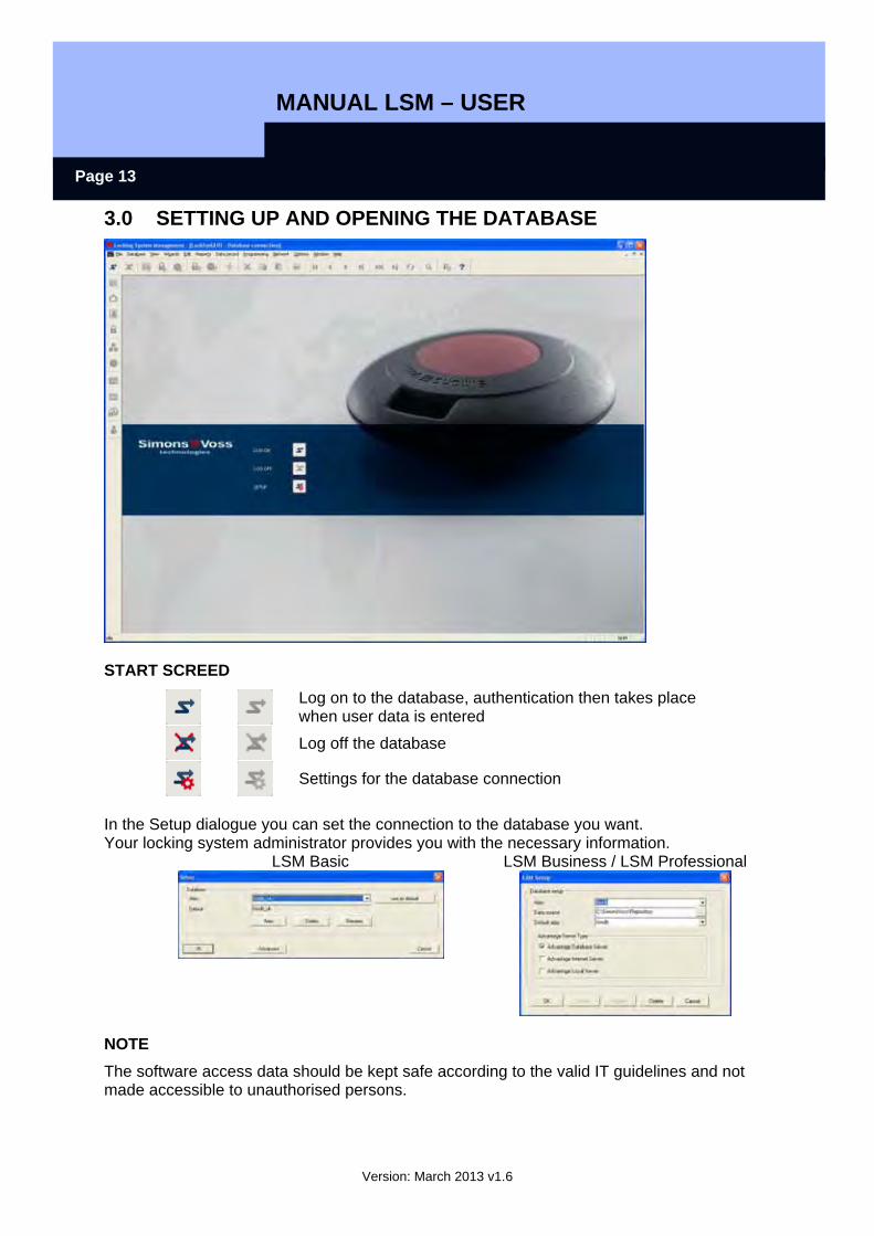
3.0 SETTING UP AND OPENING THE DATABASE
START SCREED
Log on to the database, authentication then takes place when user data is entered
Log off the database
Settings for the database connection
In the Setup dialogue you can set the connection to the database you want. Your locking system administrator provides you with the necessary information.
LSM Basic LSM Business / LSM Professional
NOTE
The software access data should be kept safe according to the valid IT guidelines and not made accessible to unauthorised persons.
LSM USER MANUAL Page 14
Version: March 2013 v1.6
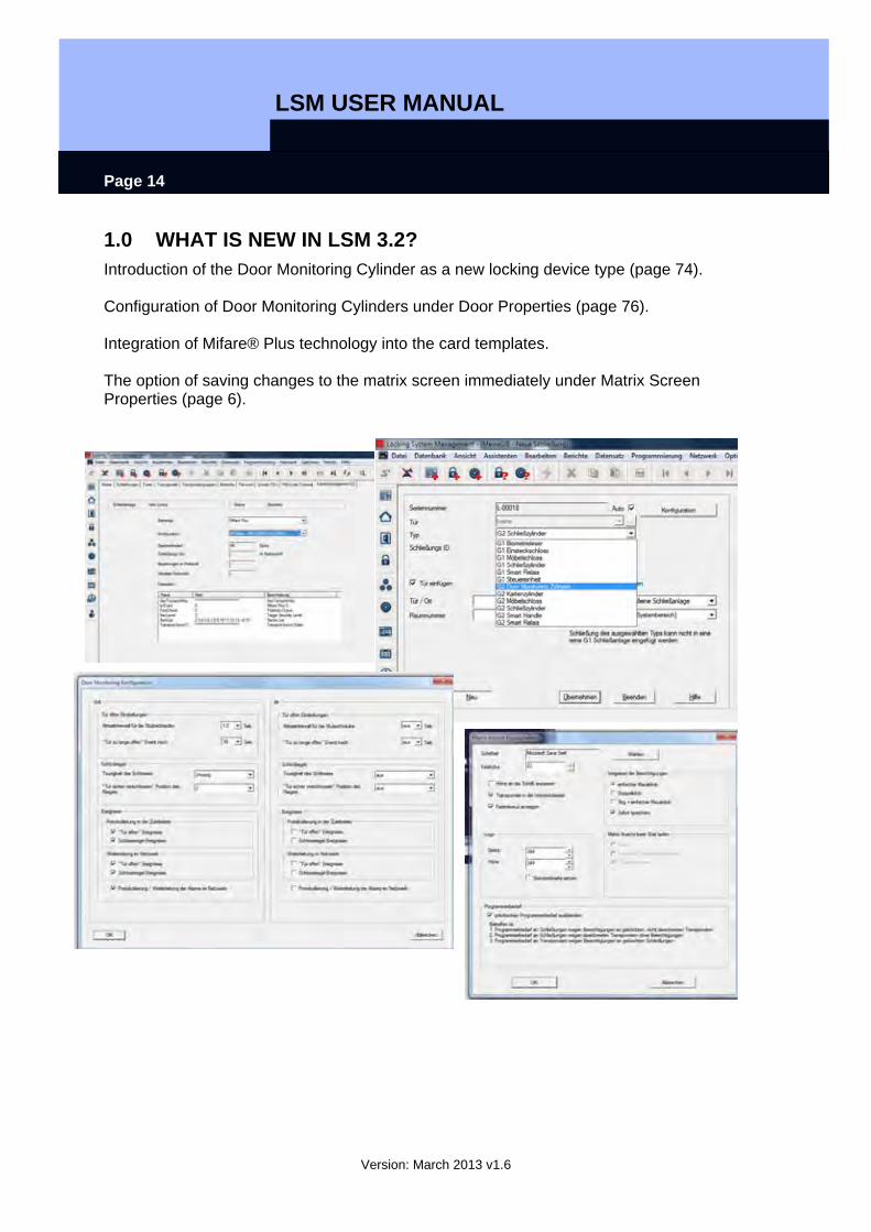
1.0 WHAT IS NEW IN LSM 3.2? Introduction of the Door Monitoring Cylinder as a new locking device type (page 74). Configuration of Door Monitoring Cylinders under Door Properties (page 76). Integration of Mifare® Plus technology into the card templates. The option of saving changes to the matrix screen immediately under Matrix Screen Properties (page 6).
LSM USER MANUAL Page 15
Version: March 2013 v1.6
2.0 VIEWS AND NAVIGATING
2.1. AREAS / TRANSPONDER GROUPS VIEW
2.1.1 GENERAL
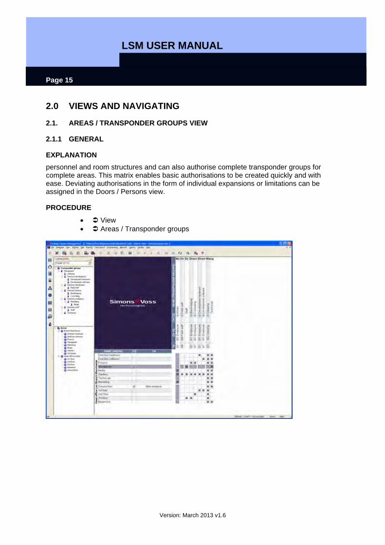
EXPLANATION personnel and room structures and can also authorise complete transponder groups for complete areas. This matrix enables basic authorisations to be created quickly and with ease. Deviating authorisations in the form of individual expansions or limitations can be assigned in the Doors / Persons view.
PROCEDURE
• View • Areas / Transponder groups

LSM USER MANUAL Page 16
Version: March 2013 v1.6
2.2. DOORS / PERSONS VIEW
2.2.1 GENERAL
EXPLANATION In this view you can see the individual authorisations of all persons for individual doors. This results in a very large matrix but does allow you to set specific exceptional authorisations. You can either expand or reduce previously set group authorisations. This view is therefore suitable for implementing individual expansions or limitations after defining the basic structure in the Areas / Transponder groups view.
PROCEDURE
• View • Doors / Persons
LSM USER MANUAL Page 17
Version: March 2013 v1.6
2.3. NAVIGATING
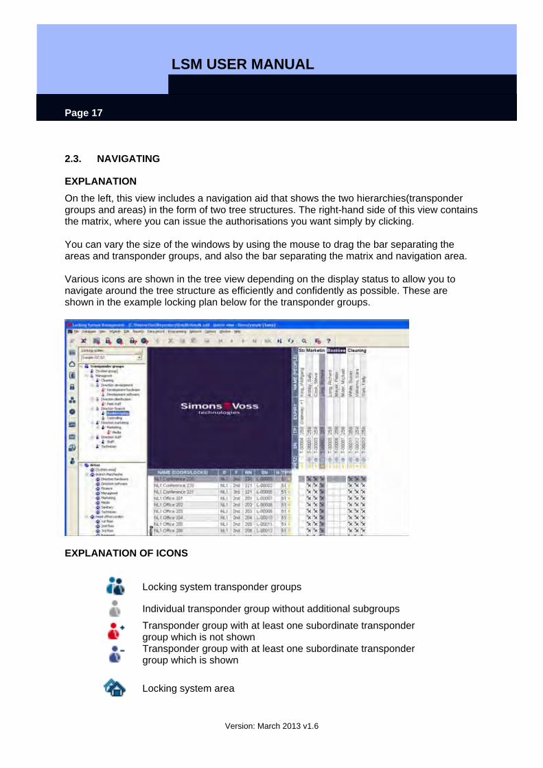
EXPLANATION On the left, this view includes a navigation aid that shows the two hierarchies(transponder groups and areas) in the form of two tree structures. The right-hand side of this view contains the matrix, where you can issue the authorisations you want simply by clicking. You can vary the size of the windows by using the mouse to drag the bar separating the areas and transponder groups, and also the bar separating the matrix and navigation area. Various icons are shown in the tree view depending on the display status to allow you to navigate around the tree structure as efficiently and confidently as possible. These are shown in the example locking plan below for the transponder groups.
EXPLANATION OF ICONS
Locking system transponder groups
Individual transponder group without additional subgroups
Transponder group with at least one subordinate transponder group which is not shown
Transponder group with at least one subordinate transponder group which is shown
Locking system area
LSM USER MANUAL Page 18
Version: March 2013 v1.6
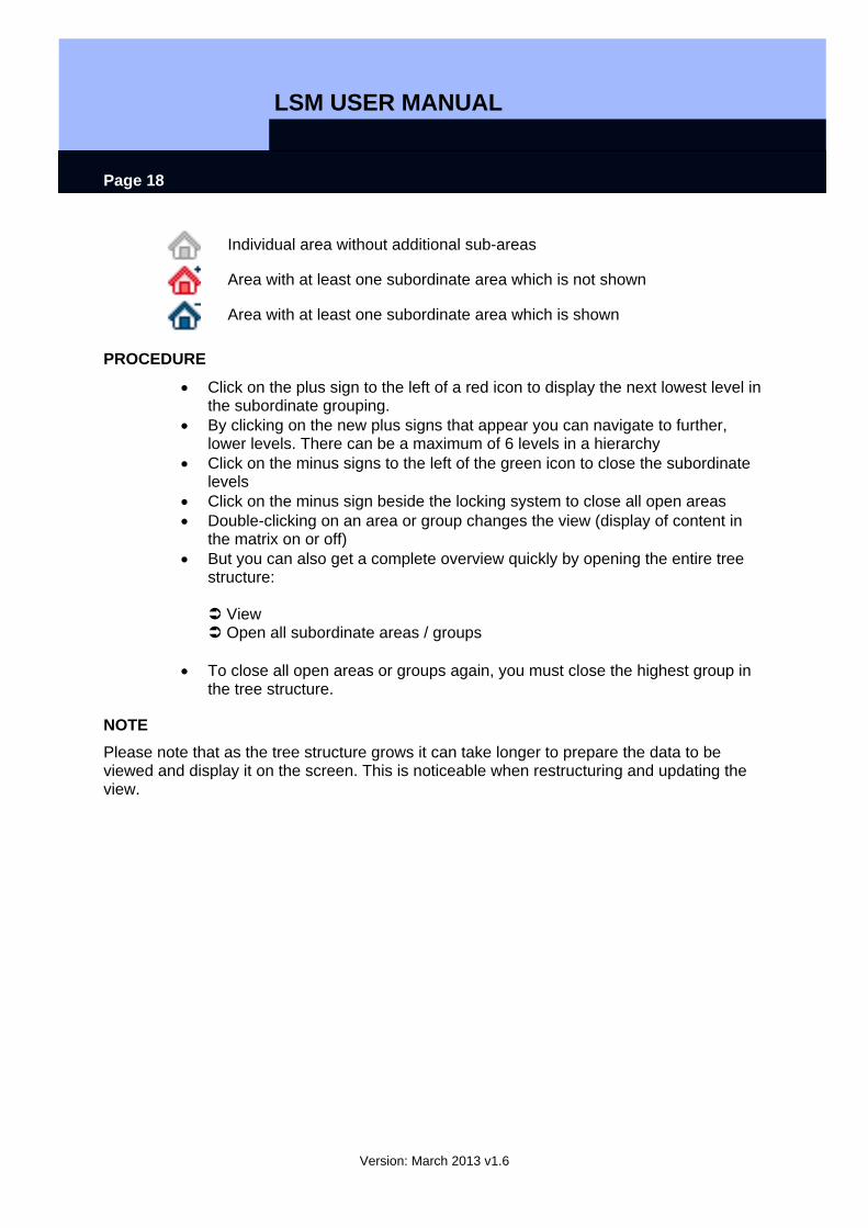
Individual area without additional sub-areas
Area with at least one subordinate area which is not shown
Area with at least one subordinate area which is shown
PROCEDURE
• Click on the plus sign to the left of a red icon to display the next lowest level in the subordinate grouping.
• By clicking on the new plus signs that appear you can navigate to further, lower levels. There can be a maximum of 6 levels in a hierarchy
• Click on the minus signs to the left of the green icon to close the subordinate levels
• Click on the minus sign beside the locking system to close all open areas • Double-clicking on an area or group changes the view (display of content in
the matrix on or off) • But you can also get a complete overview quickly by opening the entire tree
structure:
View Open all subordinate areas / groups
• To close all open areas or groups again, you must close the highest group in
the tree structure.
NOTE Please note that as the tree structure grows it can take longer to prepare the data to be viewed and display it on the screen. This is noticeable when restructuring and updating the view.

LSM USER MANUAL Page 19
Version: March 2013 v1.6
2.4. CONFIGURING STANDARD VIEW
EXPLANATION Each user can configure their preferred view as the standard view. This view is displayed once the user logs on. Various basic settings can also be activated here.
PROCEDURE
• Options • Matrix view

LSM USER MANUAL Page 20
Version: March 2013 v1.6
EXPLANATION
“Font” Standard font and font size
“Field height” Adjust the height of lines and columns
“Adapt height to font” When this option is selected, the font size and line height are automatically optimised.
“Transponders to horizontal bar”
When this option is selected, transponders / persons are positioned (horizontally) as column headings. Horizontal is standard.
“Show crosshair” Crosshair aids orientation in large matrices
“Logo” This enables you to change the size of the logo in the top left-hand corner of the matrix. This can also be done in the matrix itself by dragging the mouse. By changing the size of the logo you define the height or width of the column and row names.
“Issue authorisations” You can choose one of three options to determine when an authorisation cross is to be set and whether the change is to be implemented immediately to prevent an authorisation being issued by mistake
“Load matrix view on start-up”
Select your preferred start view and the number of groups / areas which are automatically opened. The more groups and areas displayed in the matrix, the longer it takes to structure them. You can limit the number of groups / areas to be opened to enable quicker updating and starting-up of the matrix.
“Programming requirement” This is where the display of uncritical programming requirements is controlled. These programming requirements are of minor importance for the security of the system and only appear for reasons of completeness. Since the components involved are no longer used to lock doors or the transponders had no authorisations, these programming requirements do not necessarily have to be resolved. This represents a reduction in programming in large and non-networked systems.
LSM USER MANUAL Page 21
Version: March 2013 v1.6
2.5. ADJUSTING VIEWS
2.5.1 SORTING
EXPLANATION In all matrix views it is possible to change the order of the database objects shown. You can do this in any view.
PROCEDURE
• Right-click on an area name or door designation or
• Right-click on a transponder group name or person designation • Sort group / area
NOTE You can only sort by properties that are shown in the matrix (see 1.5.2 Additional columns in label bars).
LSM USER MANUAL Page 22
Version: March 2013 v1.6
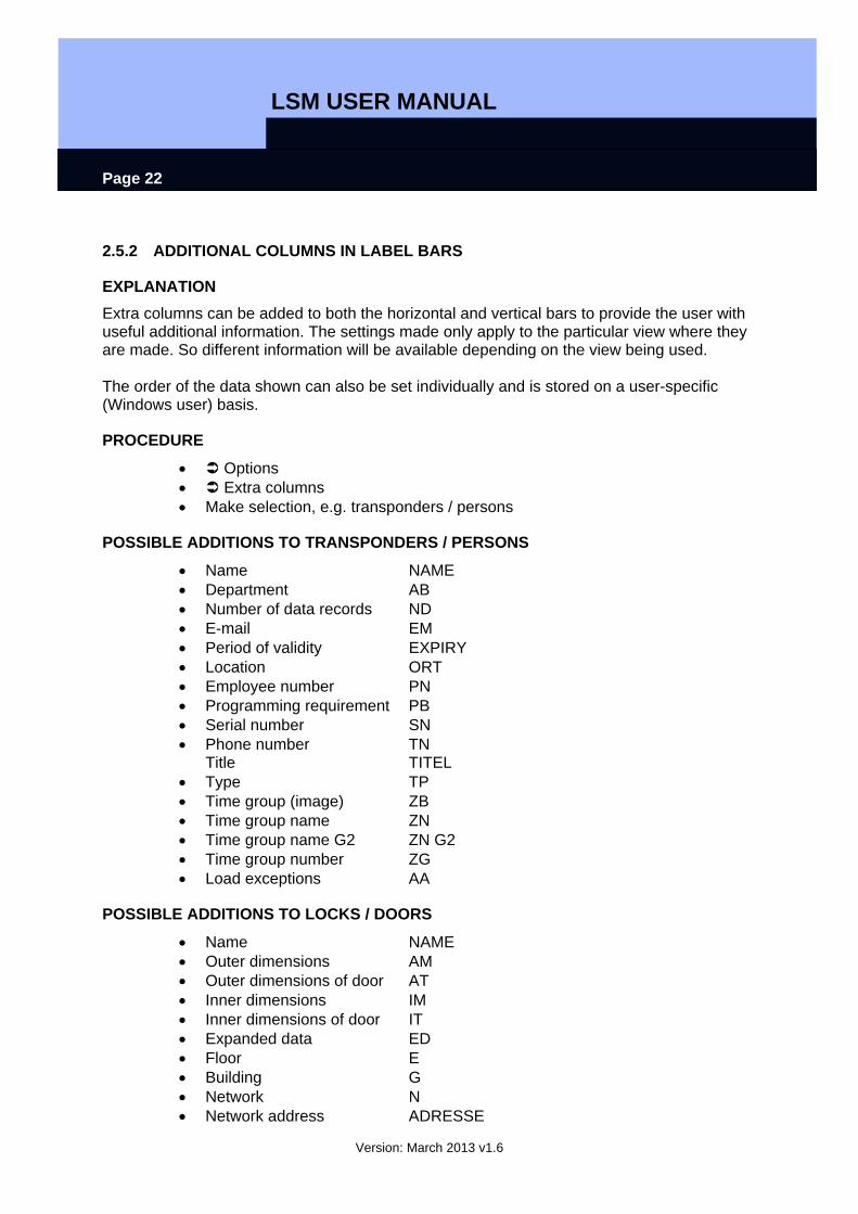
2.5.2 ADDITIONAL COLUMNS IN LABEL BARS
EXPLANATION Extra columns can be added to both the horizontal and vertical bars to provide the user with useful additional information. The settings made only apply to the particular view where they are made. So different information will be available depending on the view being used. The order of the data shown can also be set individually and is stored on a user-specific (Windows user) basis.
PROCEDURE
• Options • Extra columns • Make selection, e.g. transponders / persons
POSSIBLE ADDITIONS TO TRANSPONDERS / PERSONS
• Name NAME • Department AB • Number of data records ND • E-mail EM • Period of validity EXPIRY • Location ORT • Employee number PN • Programming requirement PB • Serial number SN • Phone number TN
Title TITEL • Type TP • Time group (image) ZB • Time group name ZN • Time group name G2 ZN G2 • Time group number ZG • Load exceptions AA
POSSIBLE ADDITIONS TO LOCKS / DOORS
• Name NAME • Outer dimensions AM • Outer dimensions of door AT • Inner dimensions IM • Inner dimensions of door IT • Expanded data ED • Floor E • Building G • Network N • Network address ADRESSE
LSM USER MANUAL Page 23
Version: March 2013 v1.6
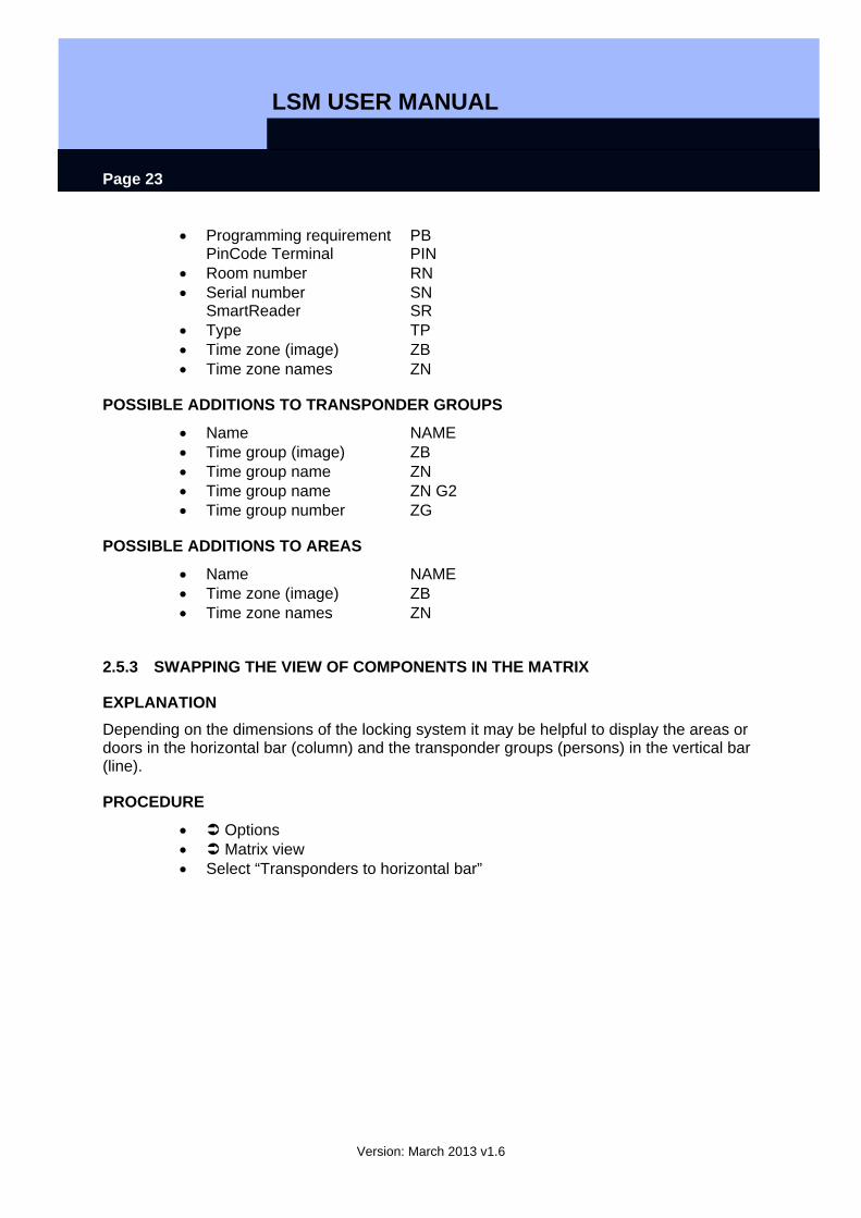
• Programming requirement PB PinCode Terminal PIN
• Room number RN • Serial number SN
SmartReader SR • Type TP • Time zone (image) ZB • Time zone names ZN
POSSIBLE ADDITIONS TO TRANSPONDER GROUPS
• Name NAME • Time group (image) ZB • Time group name ZN • Time group name ZN G2 • Time group number ZG
POSSIBLE ADDITIONS TO AREAS
• Name NAME • Time zone (image) ZB • Time zone names ZN
2.5.3 SWAPPING THE VIEW OF COMPONENTS IN THE MATRIX
EXPLANATION Depending on the dimensions of the locking system it may be helpful to display the areas or doors in the horizontal bar (column) and the transponder groups (persons) in the vertical bar (line).
PROCEDURE
• Options • Matrix view • Select “Transponders to horizontal bar”
LSM USER MANUAL Page 24
Version: March 2013 v1.6
3.0 ISSUING AUTHORISATIONS
3.1. SHOW / ISSUE GROUP AUTHORISATION
ICONS
(“Doors / Persons” view)
(“Areas / Transponder groups” view)
EXPLANATION By issuing a group authorisationyou can authorise a whole transponder group for a complete area. You can therefore create basic authorisations in the locking plan quickly and with ease. It may be useful when issuing authorisations to familiarise yourself with the intended use of the building and the organisational structure of the company in advance. Later on, a clearly structured system is a great tool for day-to-day business by making statements quickly and precisely about possible access instances and makes daily life in the company or organisation easier. You can configure exceptions to group authorisations in Doors / Persons view by removing or adding individual crosses at any time, even at a later date.
GROUP RESERVES If a transponder is assigned to a group, it immediately receives all the authorisations assigned to the group. If a new transponder is assigned to a group, the affected locks need to be programmed. To avoid this situation, so-called transponder ID reserves can be assigned to groups when they are created or at a later date. At this time, however, these transponder IDs are not assigned to a person. The reserves are stored in the locks during programming and are then available to use. If a transponder ID from this reserve is assigned to a person and the transponder is programmed, there is no need to program the locks. Transponders can therefore be automatically authorised and activated in locks without the user having to perform any additional steps such as programming the lock.
INHERITANCE Inheritance is a way of representing a company’s hierarchy in the locking system. When inheritance is implemented correctly it greatly reduces the user’s workload. It allows you to automate certain processes by assigning a transponder to a particular transponder group. Inheritance can be used when a hierarchy is in place for transponder groups and areas. Group authorisations are considered for inheritance, individual authorisations are not inherited (see LSM Administration Manual).
PROCEDURE
• View • Areas / Transponder groups • Add cross to matrix
LSM USER MANUAL Page 25
Version: March 2013 v1.6
LSM USER MANUAL Page 26
Version: March 2013 v1.6
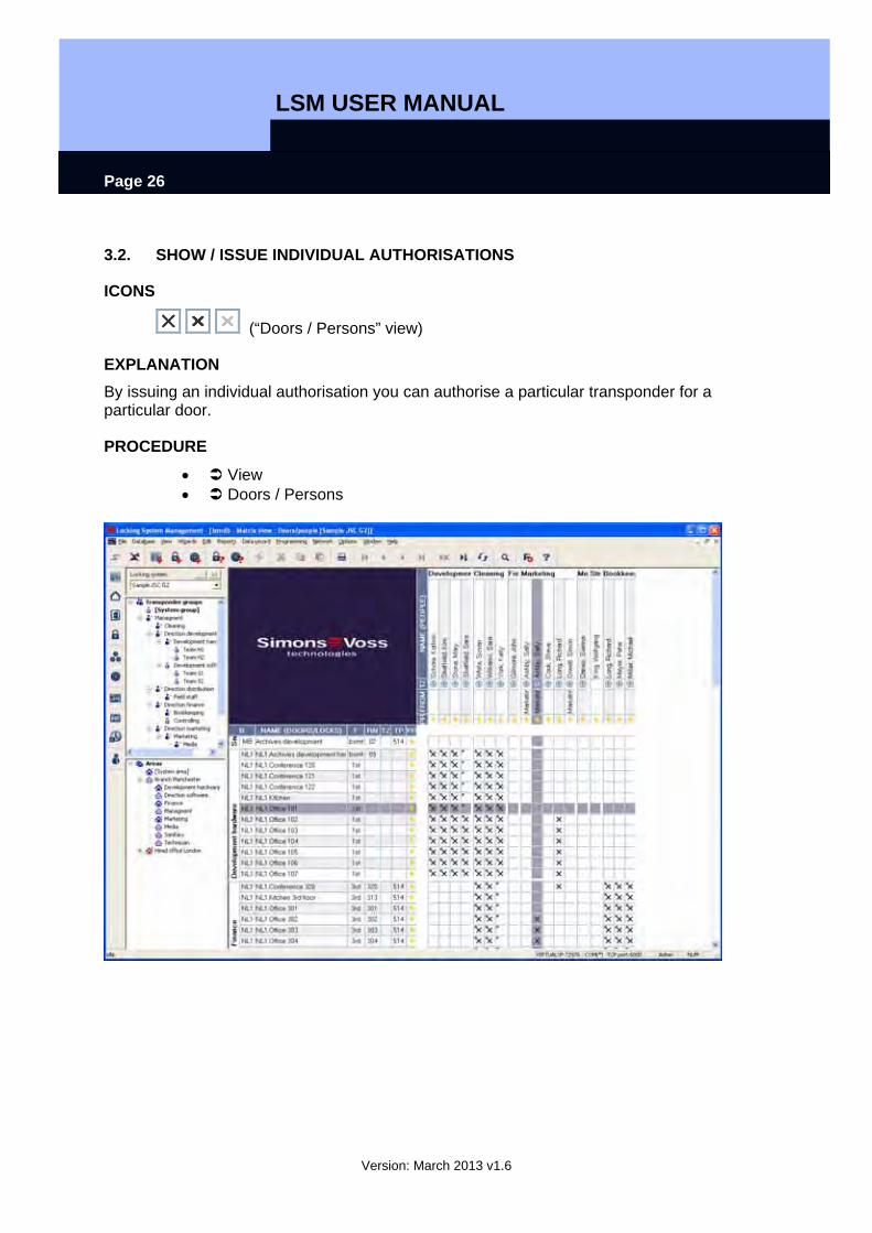
3.2. SHOW / ISSUE INDIVIDUAL AUTHORISATIONS
ICONS
(“Doors / Persons” view)
EXPLANATION By issuing an individual authorisation you can authorise a particular transponder for a particular door.
PROCEDURE
• View • Doors / Persons

LSM USER MANUAL Page 27
Version: March 2013 v1.6
4.0 SEARCH
EXPLANATION The search function is the easy way to look for various objects in the database, for example a particular door or a particular transponder. The different ways of performing a search are explained below.
PROCEDURE
• Right-click on a person or a door • Left-click on Search • Select object (there may be a preliminary selection corresponding to the
context) • Enter designation or part of designation you want to search for • Select the various search options
You can also call up the search function by clicking on the icon
Once the search results are displayed, by selecting an object you can view its properties, the object in the matrix or in a report. A multiple selection of objects can also be deleted.
LSM USER MANUAL Page 28
Version: March 2013 v1.6
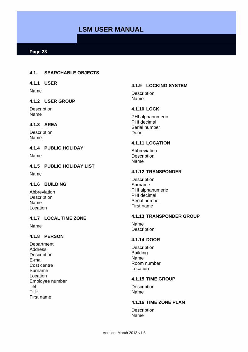
4.1. SEARCHABLE OBJECTS
4.1.1 USER Name
4.1.2 USER GROUP Description Name
4.1.3 AREA Description Name
4.1.4 PUBLIC HOLIDAY Name
4.1.5 PUBLIC HOLIDAY LIST Name
4.1.6 BUILDING Abbreviation Description Name Location
4.1.7 LOCAL TIME ZONE Name
4.1.8 PERSON Department Address Description E-mail Cost centre Surname Location Employee number Tel Title First name
4.1.9 LOCKING SYSTEM Description Name
4.1.10 LOCK PHI alphanumeric PHI decimal Serial number Door
4.1.11 LOCATION Abbreviation Description Name
4.1.12 TRANSPONDER Description Surname PHI alphanumeric PHI decimal Serial number First name
4.1.13 TRANSPONDER GROUP Name Description
4.1.14 DOOR Description Building Name Room number Location
4.1.15 TIME GROUP Description Name
4.1.16 TIME ZONE PLAN Description Name

LSM USER MANUAL
Version: March 2013 v1.6
Page 29
5.0 FILTERS
5.1. GENERAL INFORMATION ABOUT FILTERS
EXPLANATION The introduction of filtershas made it even easier to administer a locking system. You can select a wide range of filter options and make these filters available to a wide range of people or groups of people. The option of displaying additional columns provides you with extra information, while the filter function also enables you to keep the information on your screen clear and manageable.
5.2. MANAGING / CREATING FILTERS
PROCEDURE
• View • Manage filters
EXPLANATION New Create a new filter Edit Edit a selected filter Remove Remove a selected filter Use Use the selected filter Set as default This filter is used by default Close Hide the selection

LSM USER MANUAL
Version: March 2013 v1.6
Page 30
EXPLANATION “User restriction” User or user group that can use the filter “Transponder type” Type of transponder to be displayed (e.g.
G1 transponder) “Transponder properties” Restrictions affecting the properties of the
transponder (e.g. period of validity, programming requirements)
“Transponder group list” Restrictions affecting the group(s) to which the transponder belongs (e.g. “Management” group)
“Lock type” Type of lock to be displayed (e.g. SmartRelais)
“Door / lock properties”
Restrictions affecting the properties of the lock (e.g. with network, programming requirements)
“Area list” Restrictions affecting the group(s) to which the lock belongs (e.g. “Gate” area)
LSM USER MANUAL
Version: March 2013 v1.6
Page 31
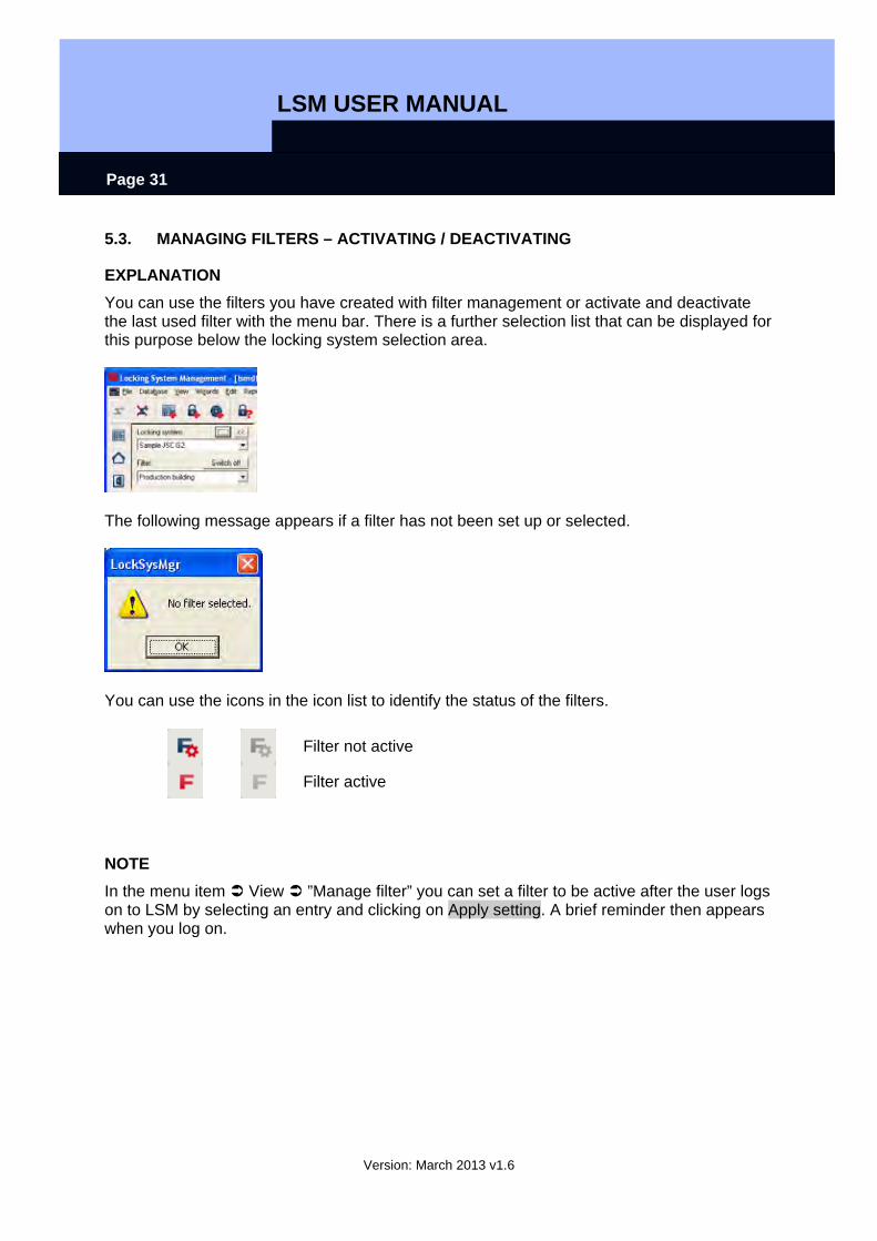
5.3. MANAGING FILTERS – ACTIVATING / DEACTIVATING
EXPLANATION You can use the filters you have created with filter management or activate and deactivate the last used filter with the menu bar. There is a further selection list that can be displayed for this purpose below the locking system selection area.
The following message appears if a filter has not been set up or selected.
You can use the icons in the icon list to identify the status of the filters.
Filter not active
Filter active
NOTE In the menu item View ”Manage filter” you can set a filter to be active after the user logs on to LSM by selecting an entry and clicking on Apply setting. A brief reminder then appears when you log on.
LSM USER MANUAL
Version: March 2013 v1.6
Page 32
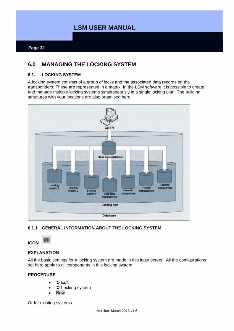
6.0 MANAGING THE LOCKING SYSTEM
6.1. LOCKING SYSTEM A locking system consists of a group of locks and the associated data records on the transponders. These are represented in a matrix. In the LSM software it is possible to create and manage multiple locking systems simultaneously in a single locking plan. The building structures with your locations are also organised here.
6.1.1 GENERAL INFORMATION ABOUT THE LOCKING SYSTEM
ICON
EXPLANATION All the basic settings for a locking system are made in this input screen. All the configurations set here apply to all components in this locking system.
PROCEDURE
• Edit • Locking system • New
Or for existing systems
LSM USER MANUAL
Version: March 2013 v1.6
Page 33
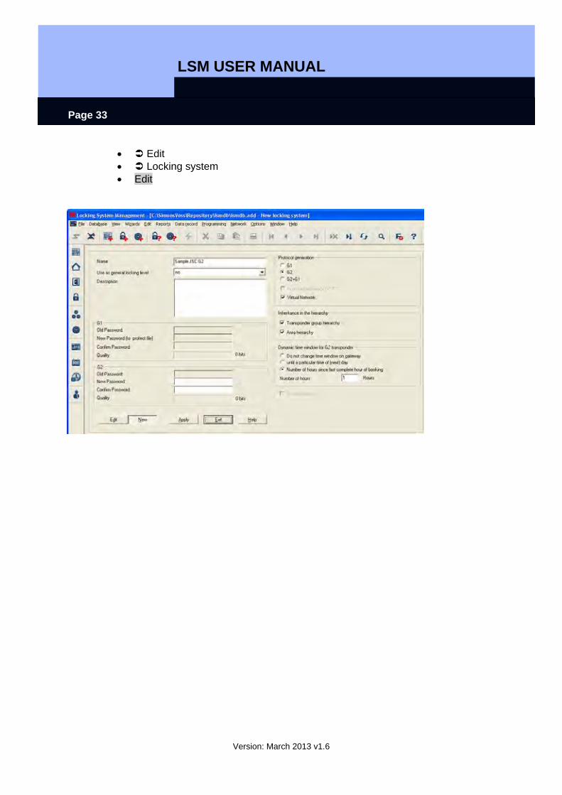
• Edit • Locking system • Edit
LSM USER MANUAL
Version: March 2013 v1.6
Page 34
EXPLANATION “Name” Designation of locking system “Use as overall locking level” Definition of overall locking level (See 10.7
Overall locking levels) “Description” Free field for describing the locking system “Old password “ If you change the password for the locking
system, it is entered here “New password” If you change the password for the locking
system, the new password is entered here “Confirm” Re-enter the new password for the locking
system to confirm it “Quality” Displays the quality (complexity) of the
password used (at least 64 bits) “Log generation” Selection of expansion variants for
hardware components “Automatically assign G1 TId” For systems in G2+G1 mode, the G2
transponder also receives G1 data for reasons of compatibility so that it can also open G1 locks.
“Virtual network” Changes to authorisations in the system are written to the transponders using gateways, this mode applies for the entire locking system
“Transponder group hierarchy” Authorisations of a transponder group are inherited by the superordinate transponder group
“Area hierarchy” Authorisations of an area are inherited by the superordinate area
Dynamic time window for G2 transponder
“Do not change time window on gateway”
The validity of the G2 transponder to be booked on the gateway is not subject to a time constraint
“Until a particular time of (next) day”
The validity of the G2 transponder to be booked on the gateway is restricted to a fixed time
“Number of hours since last complete hour of booking”
The validity of the G2 transponder to be booked on the gateway is extended by a certain number of hours
“Operate in overlay mode ” Activates overlay mode (see 10.6 Overlay mode)
LSM USER MANUAL
Version: March 2013 v1.6
Page 35
6.1.2 LOCKING SYSTEM PROPERTIES
EXPLANATION In the locking system properties you can modify or view all information relating to the locking system. You can navigate to the individual properties using the tabs at the top.
PROCEDURE
• Edit • Locking system properties
or • Right-click on the locking system icon in the hierarchy tree • Left-click on Properties
LSM USER MANUAL
Version: March 2013 v1.6
Page 36
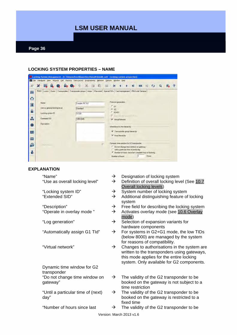
LOCKING SYSTEM PROPERTIES – NAME
EXPLANATION “Name” Designation of locking system “Use as overall locking level” Definition of overall locking level (See 10.7
Overall locking levels) “Locking system ID” System number of locking system “Extended SID” Additional distinguishing feature of locking
system “Description” Free field for describing the locking system “Operate in overlay mode ” Activates overlay mode (see 10.6 Overlay
mode) “Log generation” Selection of expansion variants for
hardware components “Automatically assign G1 TId” For systems in G2+G1 mode, the low TIDs
(below 8000) are managed by the system for reasons of compatibility.
“Virtual network” Changes to authorisations in the system are written to the transponders using gateways, this mode applies for the entire locking system. Only available for G2 components.
Dynamic time window for G2 transponder
“Do not change time window on gateway”
The validity of the G2 transponder to be booked on the gateway is not subject to a time restriction
“Until a particular time of (next) day”
The validity of the G2 transponder to be booked on the gateway is restricted to a fixed time
“Number of hours since last The validity of the G2 transponder to be
LSM USER MANUAL
Version: March 2013 v1.6
Page 37
complete hour of booking” booked on the gateway is extended by a certain number of hours
LSM USER MANUAL
Version: March 2013 v1.6
Page 38
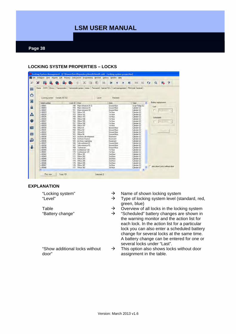
LOCKING SYSTEM PROPERTIES – LOCKS
EXPLANATION “Locking system” Name of shown locking system “Level” Type of locking system level (standard, red,
green, blue) Table Overview of all locks in the locking system “Battery change” “Scheduled” battery changes are shown in
the warning monitor and the action list for each lock. In the action list for a particular lock you can also enter a scheduled battery change for several locks at the same time. A battery change can be entered for one or several locks under “Last”.
“Show additional locks without door”
This option also shows locks without door assignment in the table.

LSM USER MANUAL
Version: March 2013 v1.6
Page 39
LOCKING SYSTEM PROPERTIES – DOORS
EXPLANATION Table Overview of all doors in the locking system “Change assignment to area” You can change the area assignment of one
or more doors at the same time. “Change assignment in the building structure”
You can change the location, building assignment or floor of one or more doors at the same time. The locations and buildings must be created in advance.

LSM USER MANUAL
Version: March 2013 v1.6
Page 40
LOCKING SYSTEM PROPERTIES – TRANSPONDERS IN G1 SYSTEMS
EXPLANATION Table Overview of all transponders in the locking
system “Do not modify groups” The selected transponder(s) are relocated
to a different group. The transponders are given a TID from the reserve for the new transponder group. This means the transponders will need to be programmed.
“Do not modify transponders” The selected transponder(s) are relocated to a different group. The transponders keep the same transponder ID. This means the locks for which the transponder’s old and new transponder groups are authorised will need to be programmed.
LSM USER MANUAL
Version: March 2013 v1.6
Page 41
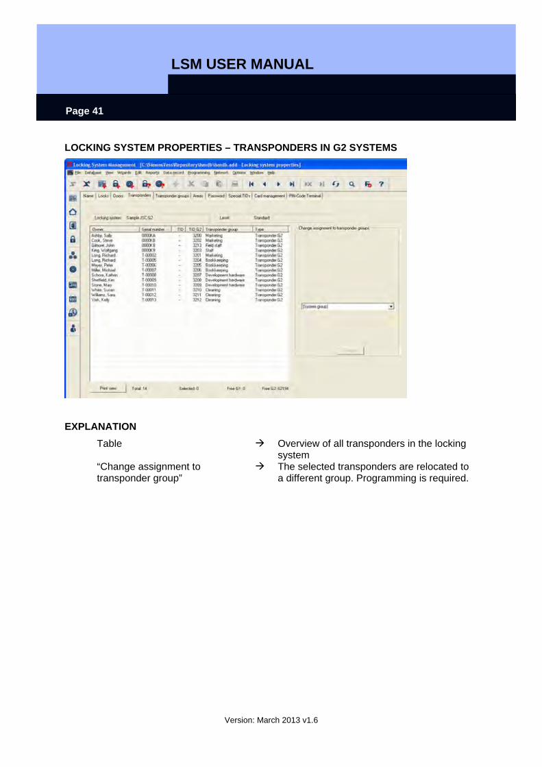
LOCKING SYSTEM PROPERTIES – TRANSPONDERS IN G2 SYSTEMS
EXPLANATION Table Overview of all transponders in the locking
system “Change assignment to transponder group”
The selected transponders are relocated to a different group. Programming is required.
LSM USER MANUAL
Version: March 2013 v1.6
Page 42
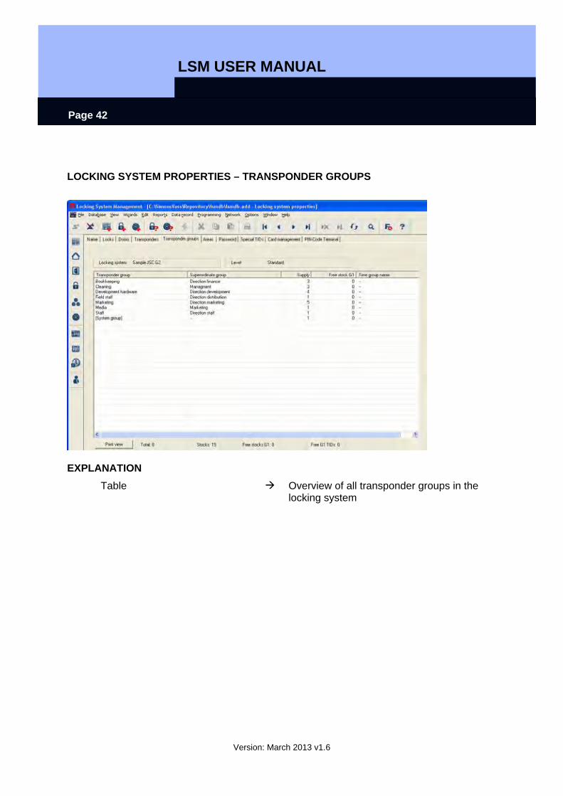
LOCKING SYSTEM PROPERTIES – TRANSPONDER GROUPS
EXPLANATION Table Overview of all transponder groups in the
locking system
LSM USER MANUAL
Version: March 2013 v1.6
Page 43
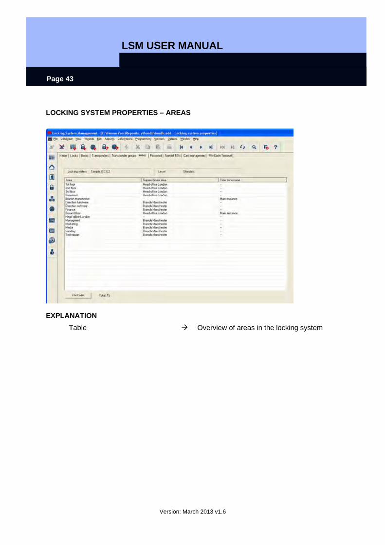
LOCKING SYSTEM PROPERTIES – AREAS
EXPLANATION Table Overview of areas in the locking system
LSM USER MANUAL
Version: March 2013 v1.6
Page 44
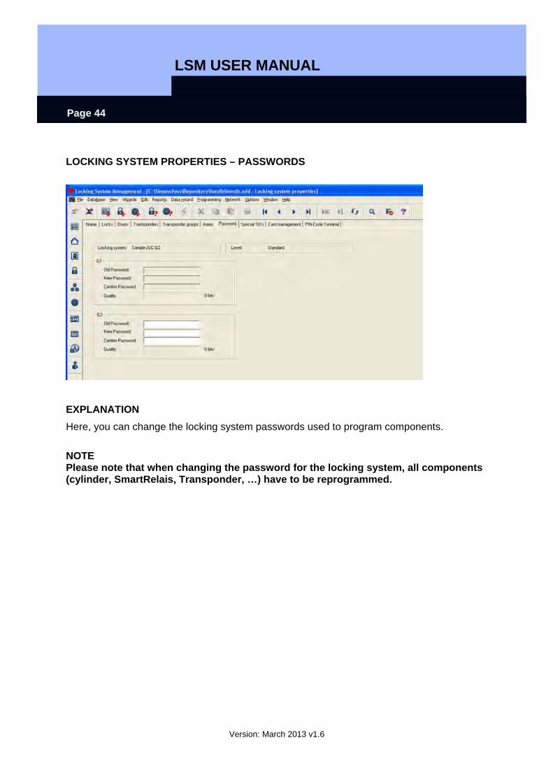
LOCKING SYSTEM PROPERTIES – PASSWORDS
EXPLANATION Here, you can change the locking system passwords used to program components.
NOTE Please note that when changing the password for the locking system, all components (cylinder, SmartRelais, Transponder, …) have to be reprogrammed.
LSM USER MANUAL
Version: March 2013 v1.6
Page 45
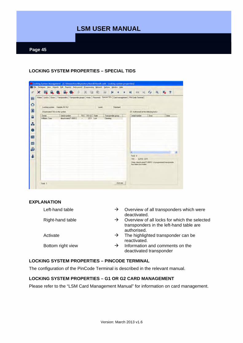
LOCKING SYSTEM PROPERTIES – SPECIAL TIDS
EXPLANATION Left-hand table Overview of all transponders which were
deactivated. Right-hand table Overview of all locks for which the selected
transponders in the left-hand table are authorised.
Activate The highlighted transponder can be reactivated.
Bottom right view Information and comments on the deactivated transponder
LOCKING SYSTEM PROPERTIES – PINCODE TERMINAL The configuration of the PinCode Terminal is described in the relevant manual.
LOCKING SYSTEM PROPERTIES – G1 OR G2 CARD MANAGEMENT Please refer to the “LSM Card Management Manual” for information on card management.
LSM USER MANUAL
Version: March 2013 v1.6
Page 46
6.1.3 CREATING A LOCKING SYSTEM
PROCEDURE
• Edit • Locking system • New • Enter details of locking system • Apply
or • Ctrl+Shift+A • New • Enter details of locking system • Apply
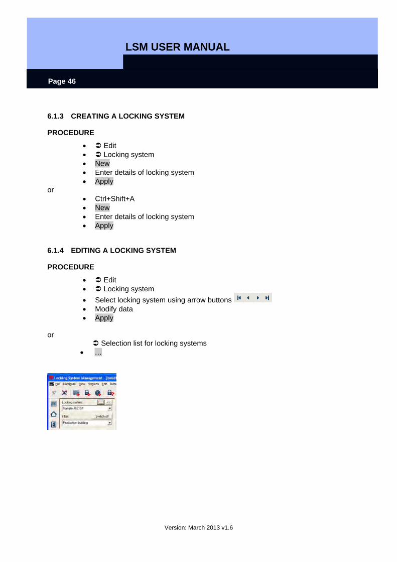
6.1.4 EDITING A LOCKING SYSTEM
PROCEDURE
• Edit • Locking system • Select locking system using arrow buttons • Modify data • Apply
or
Selection list for locking systems • …
LSM USER MANUAL
Version: March 2013 v1.6
Page 47
6.2. TRANSPONDER GROUP
6.2.1 GENERAL
ICONS
Matrix Menu item
EXPLANATION The transponder group is a set of different transponders. This set is used to issue the transponders with authorisations for certain areas on the assigned doors
EXAMPLE Staff in Marketing with the transponders assigned to them for the office doors in Marketing.
PROCEDURE
• Edit • Transponder group
or • Right-click on a transponder group • Left-click on Properties
or • Double-click on the transponder group designation in the matrix
6.2.2 CREATING A TRANSPONDER GROUP
PROCEDURE
• Edit • Transponder group • New • Select locking system • Give “transponder group” a name, for example “Marketing”. • For transponder groups lower down in the hierarchy you must select a
superordinate transponder group. When you click Apply the transponder group is saved. You can now create a second group, as the “New” button has already been activated.
LSM USER MANUAL
Version: March 2013 v1.6
Page 48
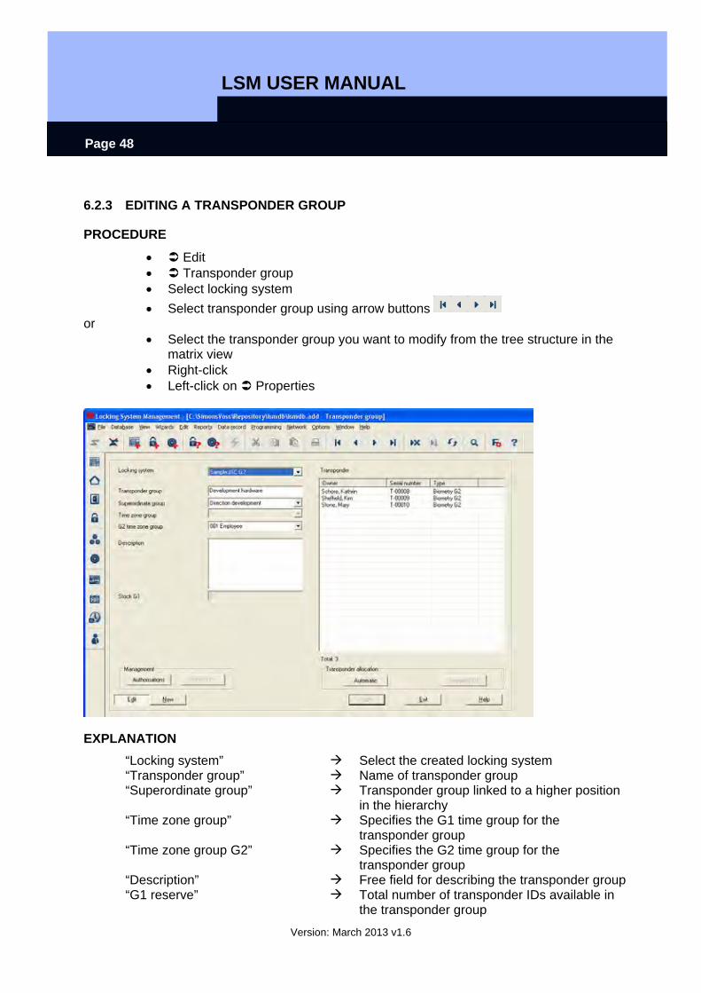
6.2.3 EDITING A TRANSPONDER GROUP
PROCEDURE
• Edit • Transponder group • Select locking system • Select transponder group using arrow buttons
or • Select the transponder group you want to modify from the tree structure in the
matrix view • Right-click • Left-click on Properties
EXPLANATION “Locking system” Select the created locking system “Transponder group” Name of transponder group “Superordinate group” Transponder group linked to a higher position
in the hierarchy “Time zone group” Specifies the G1 time group for the
transponder group “Time zone group G2” Specifies the G2 time group for the
transponder group “Description” Free field for describing the transponder group “G1 reserve” Total number of transponder IDs available in
the transponder group
LSM USER MANUAL
Version: March 2013 v1.6
Page 49
Authorisations Option of issuing group authorisations Reserve (G1) Option of managing G1 transponder IDs Automatic Option of automatically assigning a free
transponder to the transponder group Manual (G1) Option of manually assigning a particular
transponder to a particular transponder ID
LSM USER MANUAL
Version: March 2013 v1.6
Page 50
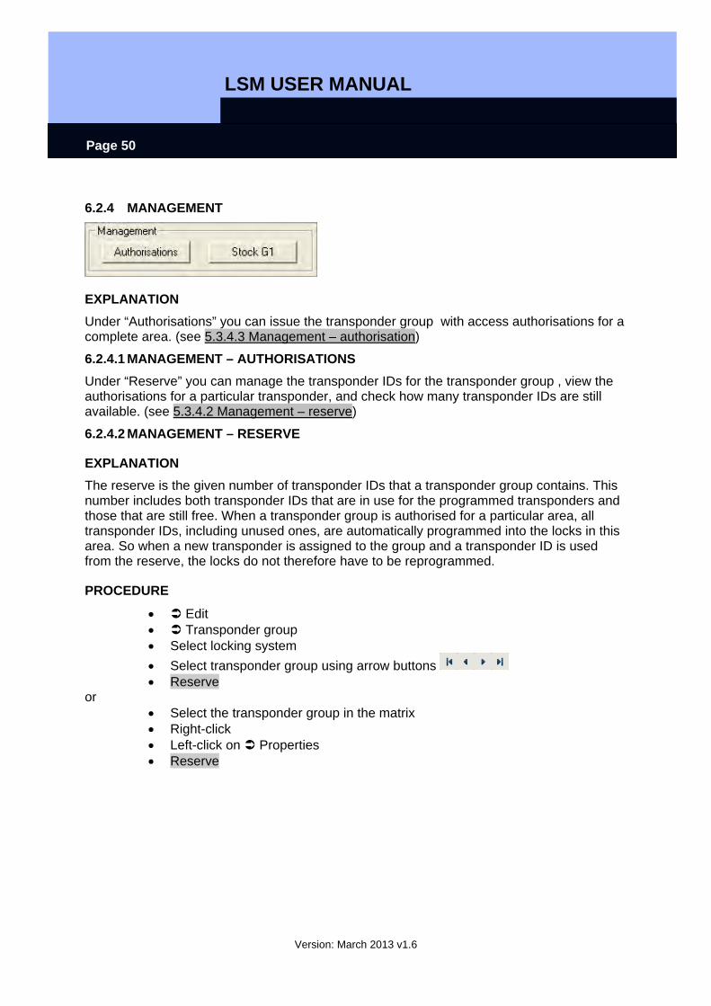
6.2.4 MANAGEMENT
EXPLANATION Under “Authorisations” you can issue the transponder group with access authorisations for a complete area. (see 5.3.4.3 Management – authorisation)
6.2.4.1 MANAGEMENT – AUTHORISATIONS Under “Reserve” you can manage the transponder IDs for the transponder group , view the authorisations for a particular transponder, and check how many transponder IDs are still available. (see 5.3.4.2 Management – reserve)
6.2.4.2 MANAGEMENT – RESERVE
EXPLANATION The reserve is the given number of transponder IDs that a transponder group contains. This number includes both transponder IDs that are in use for the programmed transponders and those that are still free. When a transponder group is authorised for a particular area, all transponder IDs, including unused ones, are automatically programmed into the locks in this area. So when a new transponder is assigned to the group and a transponder ID is used from the reserve, the locks do not therefore have to be reprogrammed.
PROCEDURE
• Edit • Transponder group • Select locking system • Select transponder group using arrow buttons • Reserve
or • Select the transponder group in the matrix • Right-click • Left-click on Properties • Reserve
LSM USER MANUAL
Version: March 2013 v1.6
Page 51
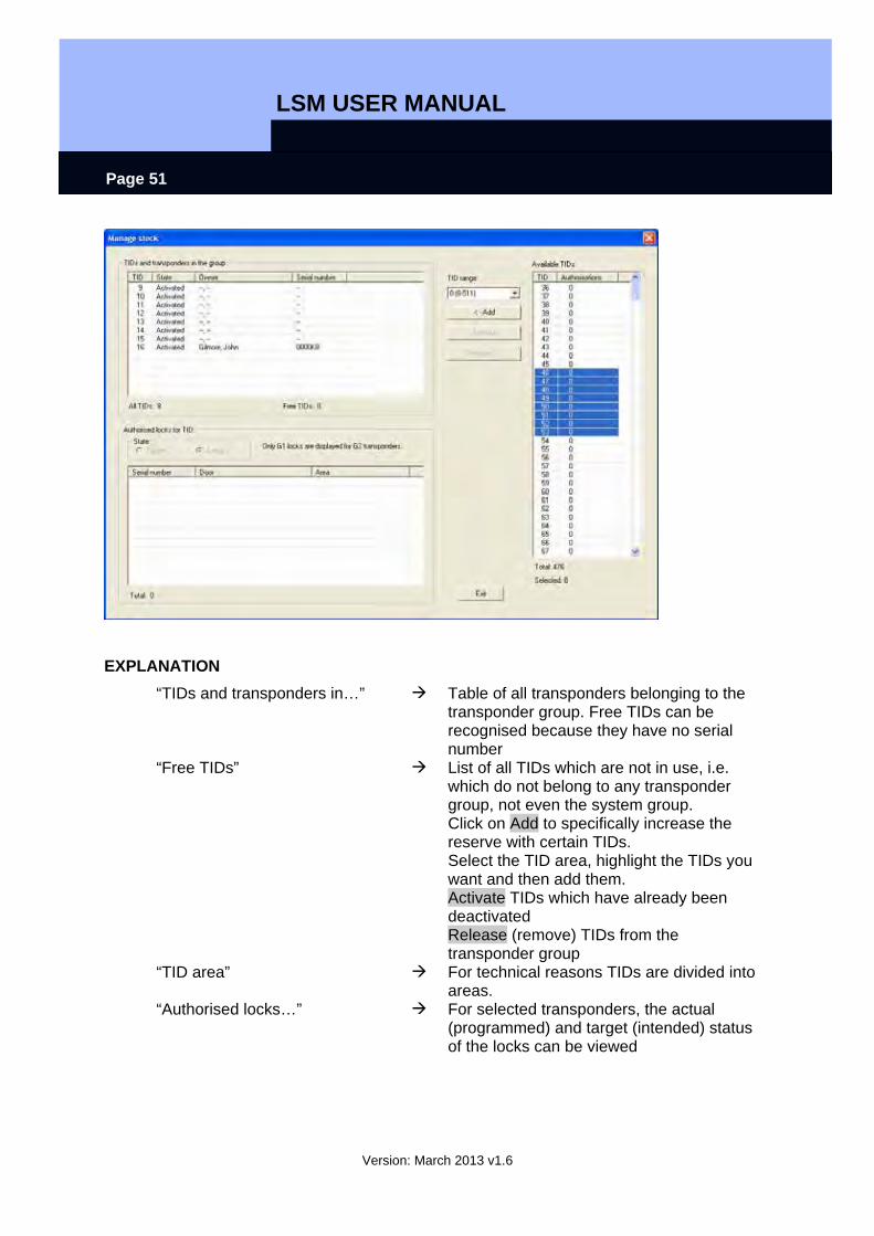
EXPLANATION “TIDs and transponders in…” Table of all transponders belonging to the
transponder group. Free TIDs can be recognised because they have no serial number
“Free TIDs” List of all TIDs which are not in use, i.e. which do not belong to any transponder group, not even the system group. Click on Add to specifically increase the reserve with certain TIDs. Select the TID area, highlight the TIDs you want and then add them. Activate TIDs which have already been deactivated Release (remove) TIDs from the transponder group
“TID area” For technical reasons TIDs are divided into areas.
“Authorised locks…” For selected transponders, the actual (programmed) and target (intended) status of the locks can be viewed
LSM USER MANUAL
Version: March 2013 v1.6
Page 52
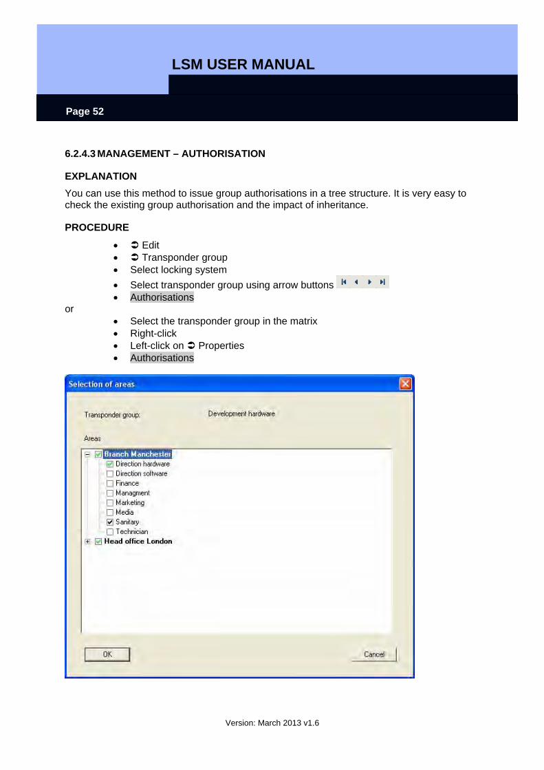
6.2.4.3 MANAGEMENT – AUTHORISATION
EXPLANATION You can use this method to issue group authorisations in a tree structure. It is very easy to check the existing group authorisation and the impact of inheritance.
PROCEDURE
• Edit • Transponder group • Select locking system • Select transponder group using arrow buttons • Authorisations
or • Select the transponder group in the matrix • Right-click • Left-click on Properties • Authorisations
LSM USER MANUAL
Version: March 2013 v1.6
Page 53
EXPLANATION You can issue group authorisations by selecting this option. The authorisation hierarchy is very easy to view and can be reproduced well. The ticks are indicated by various colours and represent the way in which authorisations are issued.
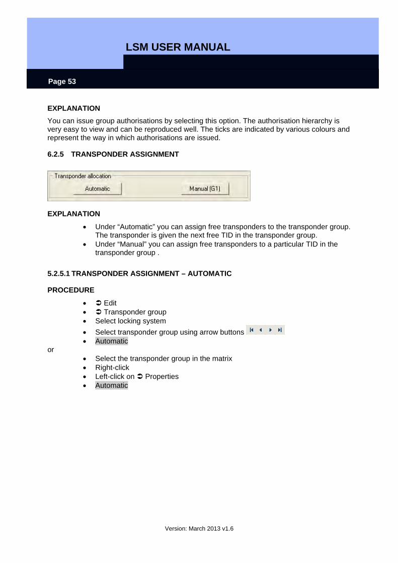
6.2.5 TRANSPONDER ASSIGNMENT
EXPLANATION
• Under “Automatic” you can assign free transponders to the transponder group. The transponder is given the next free TID in the transponder group.
• Under “Manual” you can assign free transponders to a particular TID in the transponder group .
5.2.5.1 TRANSPONDER ASSIGNMENT – AUTOMATIC
PROCEDURE
• Edit • Transponder group • Select locking system • Select transponder group using arrow buttons • Automatic
or • Select the transponder group in the matrix • Right-click • Left-click on Properties • Automatic
LSM USER MANUAL
Version: March 2013 v1.6
Page 54
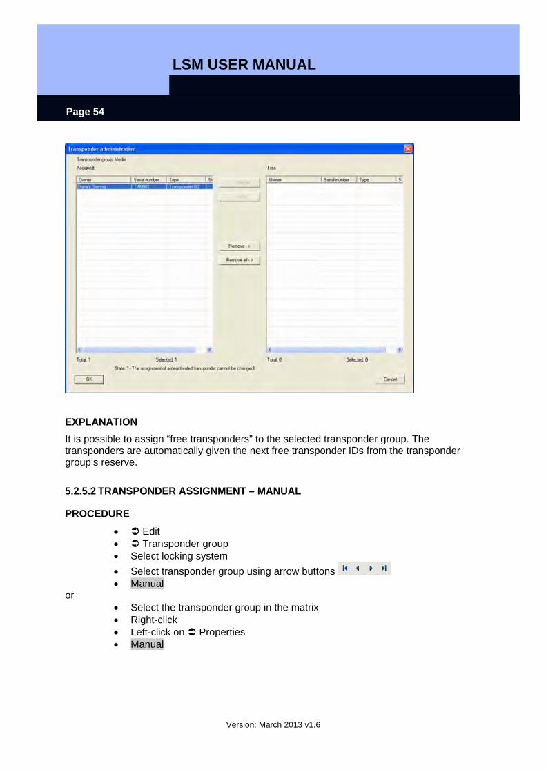
EXPLANATION It is possible to assign “free transponders” to the selected transponder group. The transponders are automatically given the next free transponder IDs from the transponder group’s reserve.
5.2.5.2 TRANSPONDER ASSIGNMENT – MANUAL
PROCEDURE
• Edit • Transponder group • Select locking system • Select transponder group using arrow buttons • Manual
or • Select the transponder group in the matrix • Right-click • Left-click on Properties • Manual
LSM USER MANUAL
Version: March 2013 v1.6
Page 55
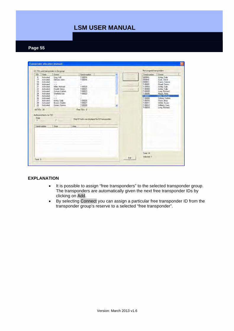
EXPLANATION
• It is possible to assign “free transponders” to the selected transponder group. The transponders are automatically given the next free transponder IDs by clicking on Add.
• By selecting Connect you can assign a particular free transponder ID from the transponder group’s reserve to a selected “free transponder”.

LSM USER MANUAL
Version: March 2013 v1.6
Page 56
6.3. TRANSPONDERS
6.3.1 GENERAL
ICON
EXPLANATION Transponders are the “keys” for digital locking systems. You can use transponders to operate digital locks. Data relevant to the locking system is stored on the transponder. This data is checked during a physical access process such that only authorised transponders have access.
PROCEDURE
• Edit • Transponder • New
Or for existing transponders
• Edit • Transponder • Edit
LSM USER MANUAL
Version: March 2013 v1.6
Page 57
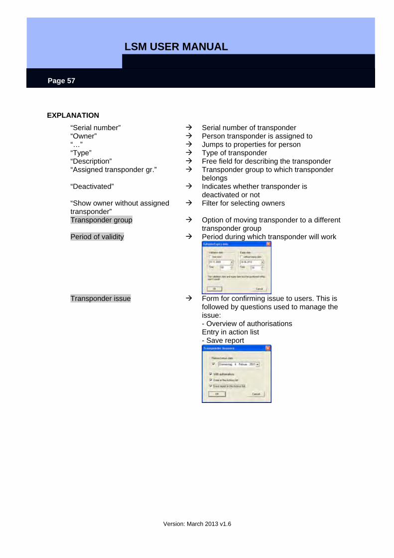
EXPLANATION “Serial number” Serial number of transponder “Owner” Person transponder is assigned to “…” Jumps to properties for person “Type” Type of transponder “Description” Free field for describing the transponder “Assigned transponder gr.” Transponder group to which transponder
belongs “Deactivated” Indicates whether transponder is
deactivated or not “Show owner without assigned transponder”
Filter for selecting owners
Transponder group Option of moving transponder to a different transponder group
Period of validity Period during which transponder will work
Transponder issue Form for confirming issue to users. This is
followed by questions used to manage the issue: - Overview of authorisations Entry in action list - Save report
LSM USER MANUAL
Version: March 2013 v1.6
Page 58
5.3.2 TRANSPONDER PROPERTIES
EXPLANATION In the transponder properties you can modify or view all information relating to the transponder. You can navigate to the individual properties using the tabs at the top.
PROCEDURE
• Edit • Transponder properties
or • Right-click on the person / transponder • Left-click on Properties • Left-click on Transponder
LSM USER MANUAL
Version: March 2013 v1.6
Page 59
TRANSPONDERS – NAME
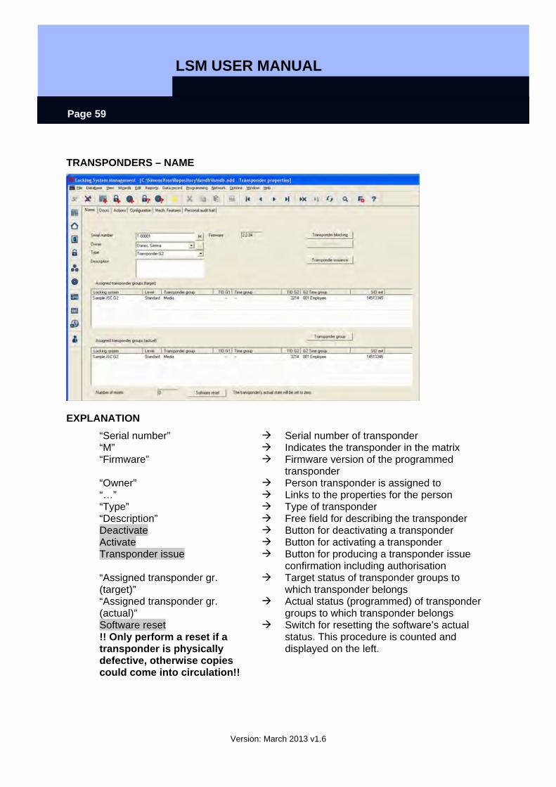
EXPLANATION “Serial number” Serial number of transponder “M” Indicates the transponder in the matrix “Firmware” Firmware version of the programmed
transponder “Owner” Person transponder is assigned to “…” Links to the properties for the person “Type” Type of transponder “Description” Free field for describing the transponder Deactivate Button for deactivating a transponder Activate Button for activating a transponder Transponder issue Button for producing a transponder issue
confirmation including authorisation “Assigned transponder gr. (target)”
Target status of transponder groups to which transponder belongs
“Assigned transponder gr. (actual)”
Actual status (programmed) of transponder groups to which transponder belongs
Software reset !! Only perform a reset if a transponder is physically defective, otherwise copies could come into circulation!!
Switch for resetting the software’s actual status. This procedure is counted and displayed on the left.
LSM USER MANUAL
Version: March 2013 v1.6
Page 60
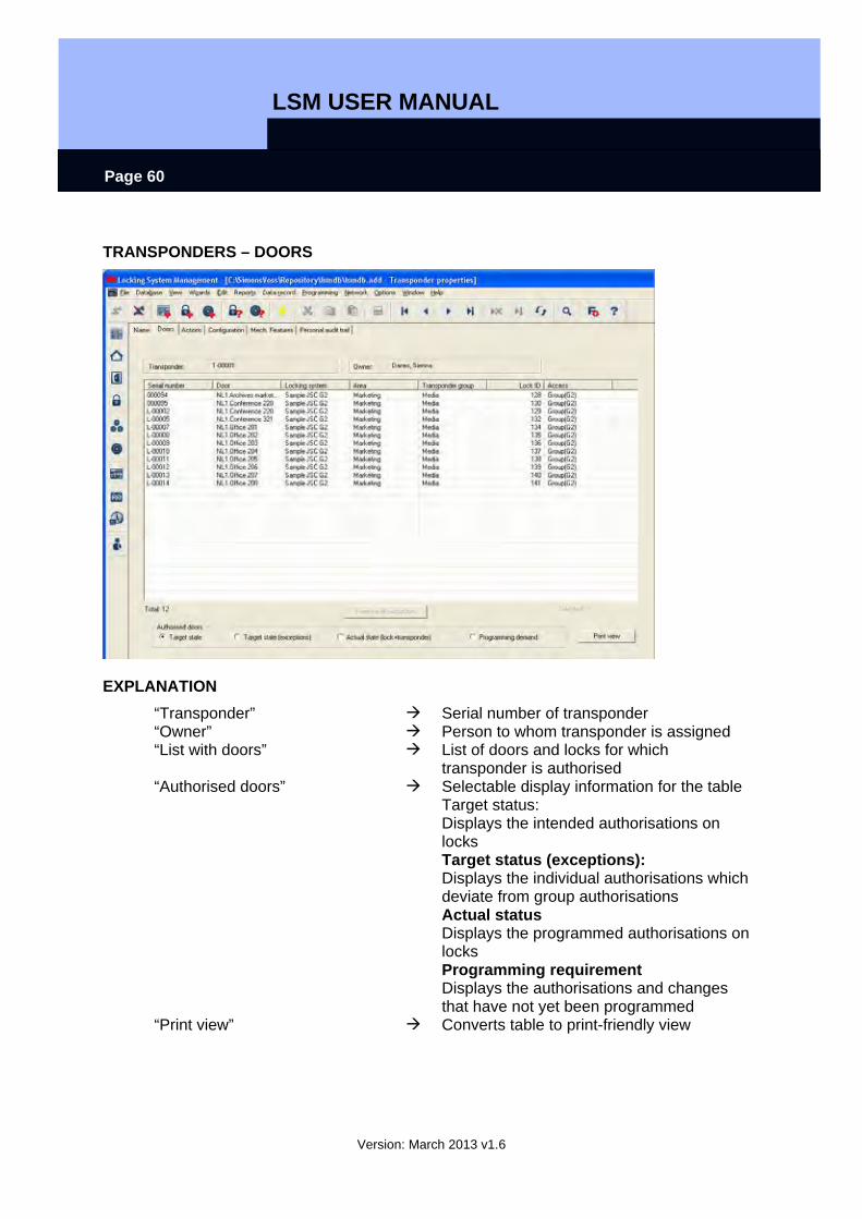
TRANSPONDERS – DOORS
EXPLANATION “Transponder” Serial number of transponder “Owner” Person to whom transponder is assigned “List with doors” List of doors and locks for which
transponder is authorised “Authorised doors” Selectable display information for the table
Target status: Displays the intended authorisations on locks Target status (exceptions): Displays the individual authorisations which deviate from group authorisations Actual status Displays the programmed authorisations on locks Programming requirement Displays the authorisations and changes that have not yet been programmed
“Print view” Converts table to print-friendly view

LSM USER MANUAL
Version: March 2013 v1.6
Page 61
TRANSPONDERS – ACTIONS
EXPLANATION “Transponder” Serial number of transponder “Owner” Person to whom transponder is assigned Table with actions
Overview of activities undertaken with the transponder. Entries are automatically created, but additional actions can also be entered and documents stored here Possible actions
• Issued • Withdrawal implemented • Withdrawal planned
Add Add can be used to create manual entries Remove Remove can be used to delete manual
entries
LSM USER MANUAL
Version: March 2013 v1.6
Page 62
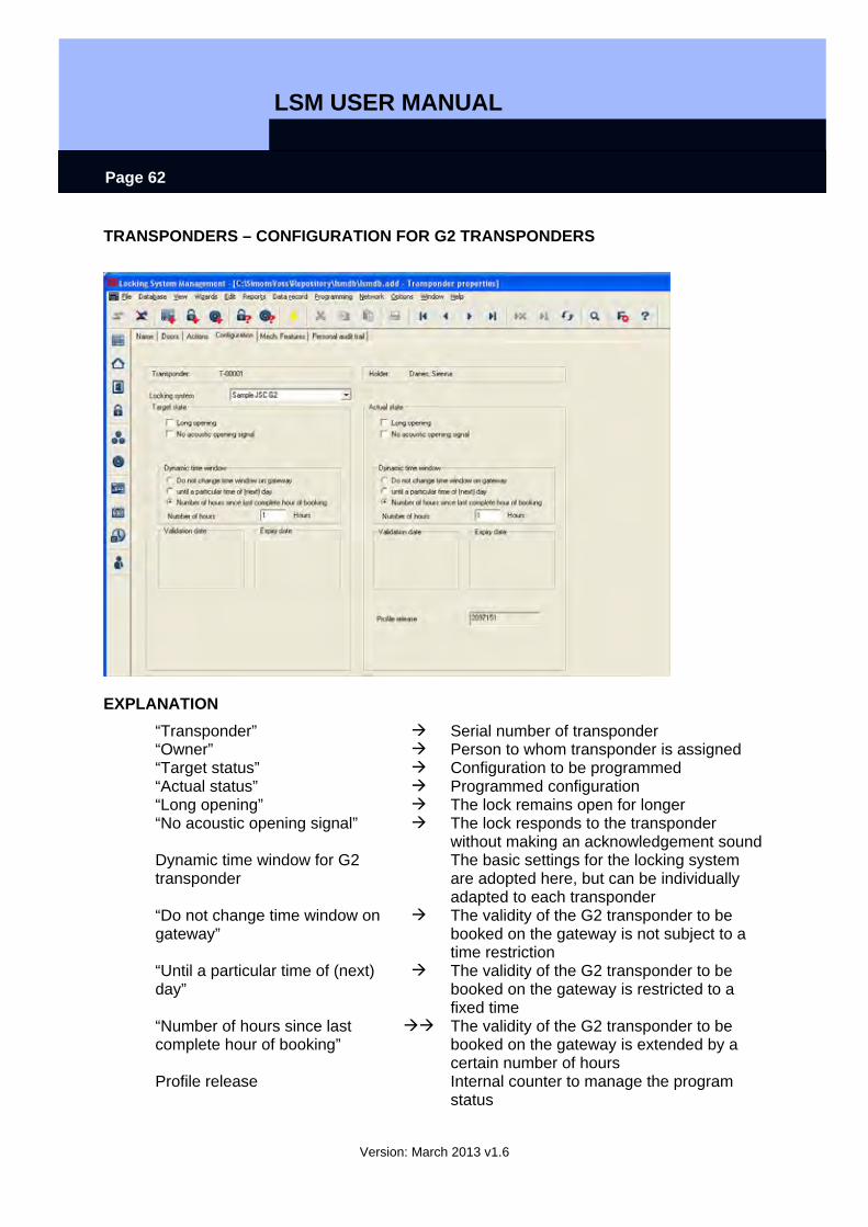
TRANSPONDERS – CONFIGURATION FOR G2 TRANSPONDERS
EXPLANATION “Transponder” Serial number of transponder “Owner” Person to whom transponder is assigned “Target status” Configuration to be programmed “Actual status” Programmed configuration “Long opening” The lock remains open for longer “No acoustic opening signal” The lock responds to the transponder
without making an acknowledgement sound Dynamic time window for G2 transponder
The basic settings for the locking system are adopted here, but can be individually adapted to each transponder
“Do not change time window on gateway”
The validity of the G2 transponder to be booked on the gateway is not subject to a time restriction
“Until a particular time of (next) day”
The validity of the G2 transponder to be booked on the gateway is restricted to a fixed time
“Number of hours since last complete hour of booking”
The validity of the G2 transponder to be booked on the gateway is extended by a certain number of hours
Profile release Internal counter to manage the program status
LSM USER MANUAL
Version: March 2013 v1.6
Page 63
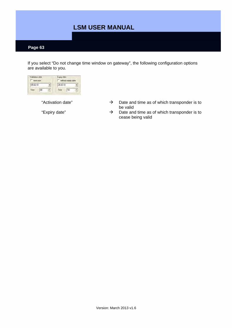
If you select “Do not change time window on gateway”, the following configuration options are available to you.
“Activation date” Date and time as of which transponder is to be valid
“Expiry date” Date and time as of which transponder is to cease being valid

LSM USER MANUAL
Version: March 2013 v1.6
Page 64
TRANSPONDERS – FITTINGS FOR G2 TRANSPONDERS
EXPLANATION “Transponder” Serial number of transponder “Owner” Person to whom transponder is assigned Data “Device class” Integration of programmed components into
a particular hardware group “PHI” Public Hardware Identifier, distinguishing
feature for hardware
LSM USER MANUAL
Version: March 2013 v1.6
Page 65
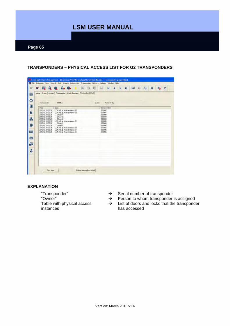
TRANSPONDERS – PHYSICAL ACCESS LIST FOR G2 TRANSPONDERS
EXPLANATION “Transponder” Serial number of transponder “Owner” Person to whom transponder is assigned Table with physical access instances
List of doors and locks that the transponder has accessed
LSM USER MANUAL
Version: March 2013 v1.6
Page 66
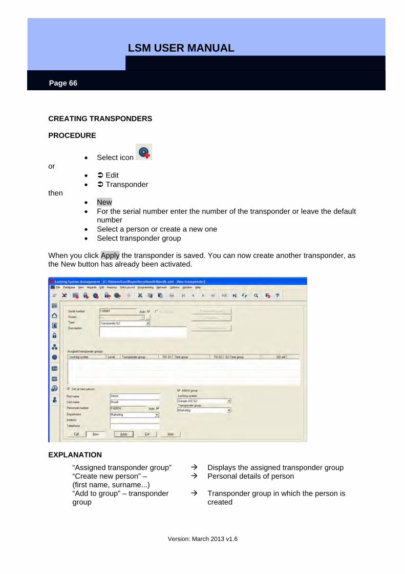
CREATING TRANSPONDERS
PROCEDURE
• Select icon or
• Edit • Transponder
then • New • For the serial number enter the number of the transponder or leave the default
number • Select a person or create a new one • Select transponder group
When you click Apply the transponder is saved. You can now create another transponder, as the New button has already been activated.
EXPLANATION “Assigned transponder group” Displays the assigned transponder group “Create new person” – (first name, surname...)
Personal details of person
“Add to group” – transponder group
Transponder group in which the person is created
LSM USER MANUAL
Version: March 2013 v1.6
Page 67
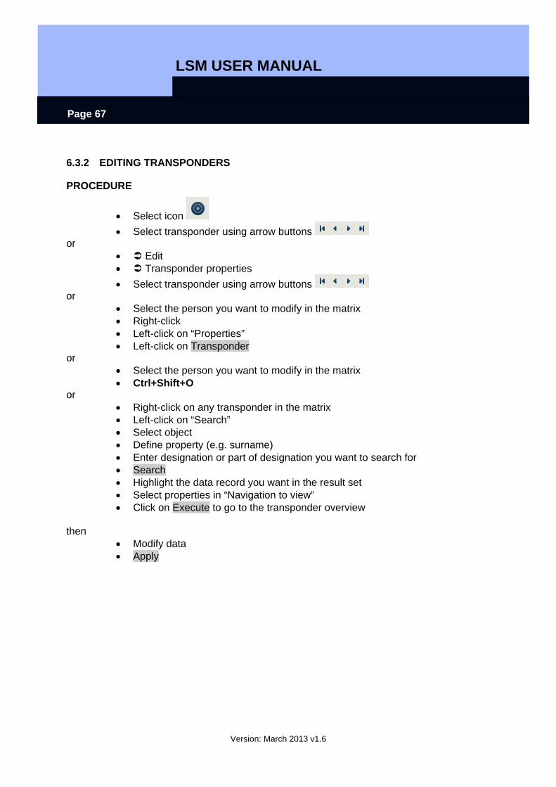
6.3.2 EDITING TRANSPONDERS
PROCEDURE
• Select icon • Select transponder using arrow buttons
or • Edit • Transponder properties • Select transponder using arrow buttons
or • Select the person you want to modify in the matrix • Right-click • Left-click on “Properties” • Left-click on Transponder
or • Select the person you want to modify in the matrix • Ctrl+Shift+O
or • Right-click on any transponder in the matrix • Left-click on “Search” • Select object • Define property (e.g. surname) • Enter designation or part of designation you want to search for • Search • Highlight the data record you want in the result set • Select properties in “Navigation to view” • Click on Execute to go to the transponder overview
then
• Modify data • Apply
LSM USER MANUAL
Version: March 2013 v1.6
Page 68
6.4. PERSONS
6.4.1 GENERAL INFORMATION ABOUT PERSONS
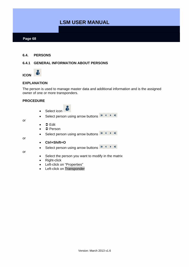
ICON
EXPLANATION The person is used to manage master data and additional information and is the assigned owner of one or more transponders.
PROCEDURE
• Select icon • Select person using arrow buttons
or • Edit • Person • Select person using arrow buttons
or • Ctrl+Shift+O • Select person using arrow buttons
or • Select the person you want to modify in the matrix • Right-click • Left-click on “Properties” • Left-click on Transponder
LSM USER MANUAL
Version: March 2013 v1.6
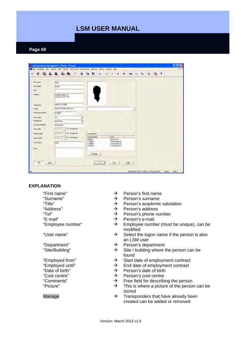
Page 69
EXPLANATION “First name” Person’s first name “Surname” Person’s surname “Title” Person’s academic salutation “Address” Person’s address “Tel” Person’s phone number “E-mail” Person’s e-mail “Employee number” Employee number (must be unique), can be
modified “User name” Select the logon name if the person is also
an LSM user “Department” Person’s department “Site/Building” Site / building where the person can be
found “Employed from” Start date of employment contract “Employed until” End date of employment contract “Date of birth” Person’s date of birth “Cost centre” Person’s cost centre “Comments” Free field for describing the person “Picture” This is where a picture of the person can be
stored Manage Transponders that have already been
created can be added or removed
LSM USER MANUAL
Version: March 2013 v1.6
Page 70
6.4.2 CREATING A PERSON
PROCEDURE
• Select icon • New
or • Edit • Person • New
or • Ctrl+Shift+P • New
then • In Manage, select a free transponder if necessary • Enter details of person • Apply
6.4.3 EDITING PERSONS
PROCEDURE
• Select icon • Select person using arrow buttons
or • Edit • Person • Select person using arrow buttons
or • Select the person you want to modify in the matrix • Right-click • Properties • Person
or • Right-click on any person in the matrix • Search • Select object • Enter designation or part of designation you want to search for • Search • Highlight the data record you want in the result set • Select properties in “Navigation to view” • Click on Execute to go to the person overview
then • Modify data • Apply
LSM USER MANUAL
Version: March 2013 v1.6
Page 71
LSM USER MANUAL
Version: March 2013 v1.6
Page 72
6.5. AREA
6.5.1 GENERAL INFORMATION ABOUT AREAS
ICON
EXPLANATION An area is a set of doors in a building or organisational unit with the same or similar transponder authorisations.
PROCEDURE
• Select icon • Select area using arrow buttons
or • Edit • Area • Select area using arrow buttons
or • Right-click on Area • Properties
or • Ctrl+Shift+S • Select area using arrow buttons
or
• Right-click on any area in the matrix • Search • Select object • Define property (e.g. name) • Enter designation or part of designation you want to search for • Search • Highlight the data record you want in the result set • Select properties in “Navigation to view” • Click on Execute to go to the area overview
LSM USER MANUAL
Version: March 2013 v1.6
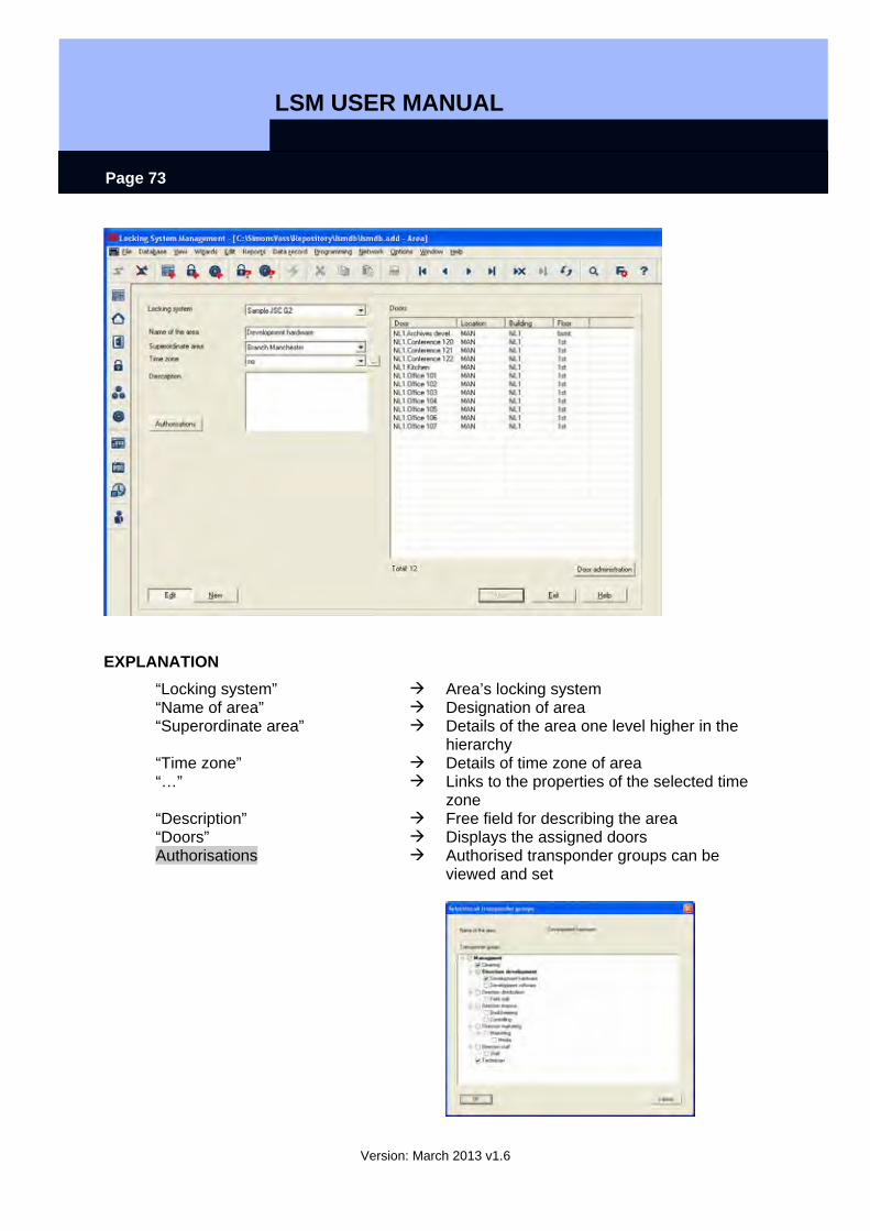
Page 73
EXPLANATION “Locking system” Area’s locking system “Name of area” Designation of area “Superordinate area” Details of the area one level higher in the
hierarchy “Time zone” Details of time zone of area “…” Links to the properties of the selected time
zone “Description” Free field for describing the area “Doors” Displays the assigned doors Authorisations Authorised transponder groups can be
viewed and set

LSM USER MANUAL
Version: March 2013 v1.6
Page 74
Door management Displays and changes the doors assigned to the area
6.5.2 CREATING AN AREA
PROCEDURE
• Select icon • Select area using arrow buttons
or • Edit • Area • Select area using arrow buttons
or • Right-click on Area • New
or • Ctrl+Shift+S
then • New • Enter details of area • Apply
6.5.3 EDITING AN AREA
PROCEDURE
• Select icon • Select area using arrow buttons
or • Edit • Area • Select area using arrow buttons
or
LSM USER MANUAL
Version: March 2013 v1.6
Page 75
• Select the area you want to modify in the matrix • Right-click on Area • Properties
or • Ctrl+Shift+S
then • Modify dataApply

LSM USER MANUAL
Version: March 2013 v1.6
Page 76
6.6. LOCK
6.6.1 GENERAL INFORMATION ABOUT LOCKS
ICON
EXPLANATION SimonsVoss describes as “locks” all products that can be operated with a transponder. This includes SmartRelais, activation units and locking cylinders, for example.
PROCEDURE
• Select icon • Select area using arrow buttons
or • Edit • Lock properties • Select lock using arrow buttons
or • Right-click on the door / lock • Properties • Lock
or • Ctrl+Shift+C
EXPLANATION “Serial number” This entry is created automatically the first
LSM USER MANUAL
Version: March 2013 v1.6
Page 77
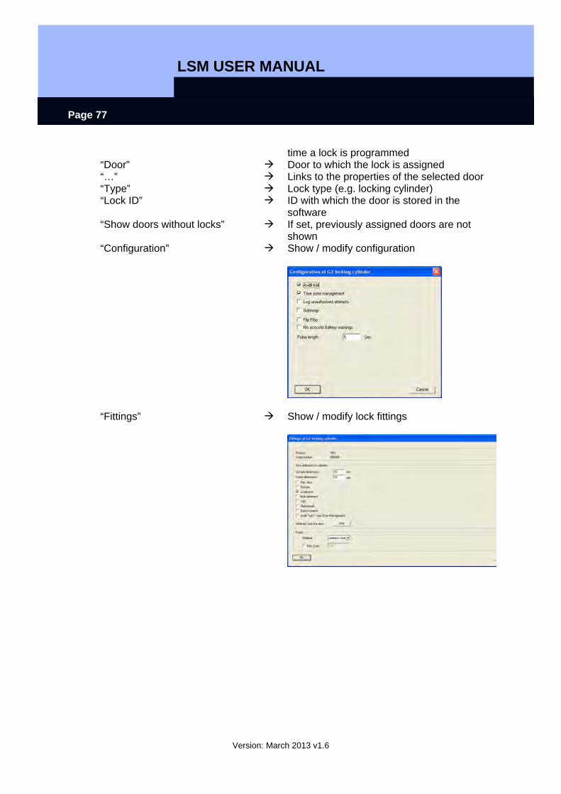
time a lock is programmed “Door” Door to which the lock is assigned “…” Links to the properties of the selected door “Type” Lock type (e.g. locking cylinder) “Lock ID” ID with which the door is stored in the
software “Show doors without locks” If set, previously assigned doors are not
shown “Configuration” Show / modify configuration
“Fittings” Show / modify lock fittings
LSM USER MANUAL
Version: March 2013 v1.6
Page 78
6.6.2 LOCK PROPERTIES
EXPLANATION In the lock properties you can modify or view all information relating to the lock. You can navigate to the individual property groups using the tabs at the top.
PROCEDURE
• Select icon • Select area using arrow buttons
or • Edit • Lock properties • Select lock using arrow buttons
or • Right-click on the door / lock • Properties • Lock
or • Ctrl+Shift+C
LSM USER MANUAL
Version: March 2013 v1.6
Page 79
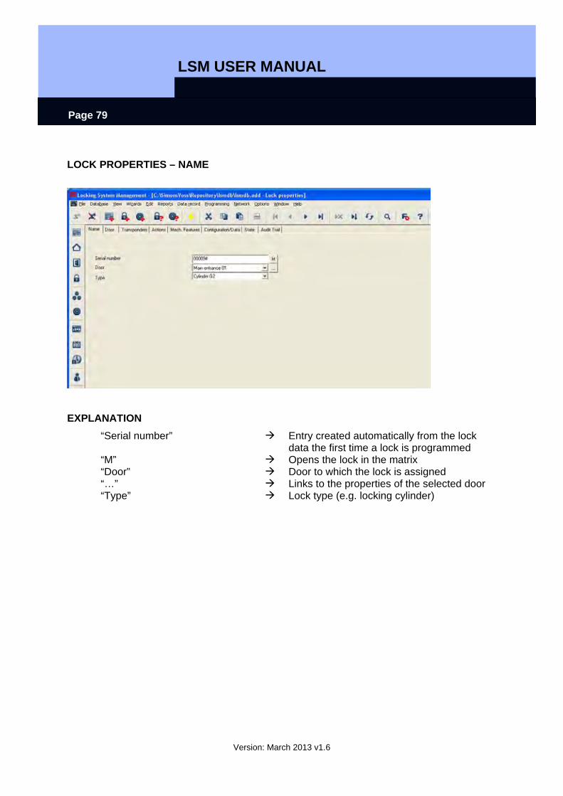
LOCK PROPERTIES – NAME
EXPLANATION “Serial number” Entry created automatically from the lock
data the first time a lock is programmed “M” Opens the lock in the matrix “Door” Door to which the lock is assigned “…” Links to the properties of the selected door “Type” Lock type (e.g. locking cylinder)
LSM USER MANUAL
Version: March 2013 v1.6
Page 80
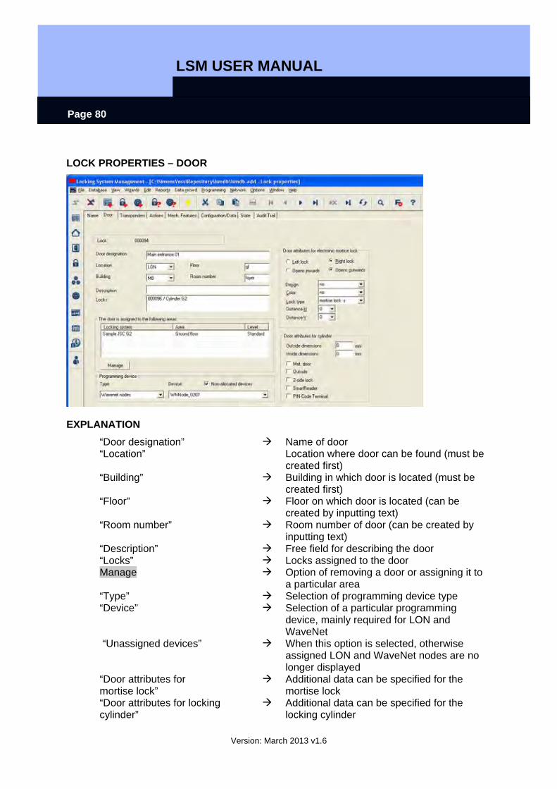
LOCK PROPERTIES – DOOR
EXPLANATION “Door designation” Name of door “Location” Location where door can be found (must be
created first) “Building” Building in which door is located (must be
created first) “Floor” Floor on which door is located (can be
created by inputting text) “Room number” Room number of door (can be created by
inputting text) “Description” Free field for describing the door “Locks” Locks assigned to the door Manage Option of removing a door or assigning it to
a particular area “Type” Selection of programming device type “Device” Selection of a particular programming
device, mainly required for LON and WaveNet
“Unassigned devices” When this option is selected, otherwise assigned LON and WaveNet nodes are no longer displayed
“Door attributes for mortise lock”
Additional data can be specified for the mortise lock
“Door attributes for locking cylinder”
Additional data can be specified for the locking cylinder
LSM USER MANUAL
Version: March 2013 v1.6
Page 81
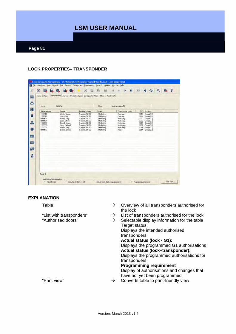
LOCK PROPERTIES– TRANSPONDER
EXPLANATION Table Overview of all transponders authorised for
the lock “List with transponders” List of transponders authorised for the lock “Authorised doors” Selectable display information for the table
Target status: Displays the intended authorised transponders Actual status (lock - G1): Displays the programmed G1 authorisations Actual status (lock+transponder): Displays the programmed authorisations for transponders Programming requirement Display of authorisations and changes that have not yet been programmed
“Print view” Converts table to print-friendly view
LSM USER MANUAL
Version: March 2013 v1.6
Page 82
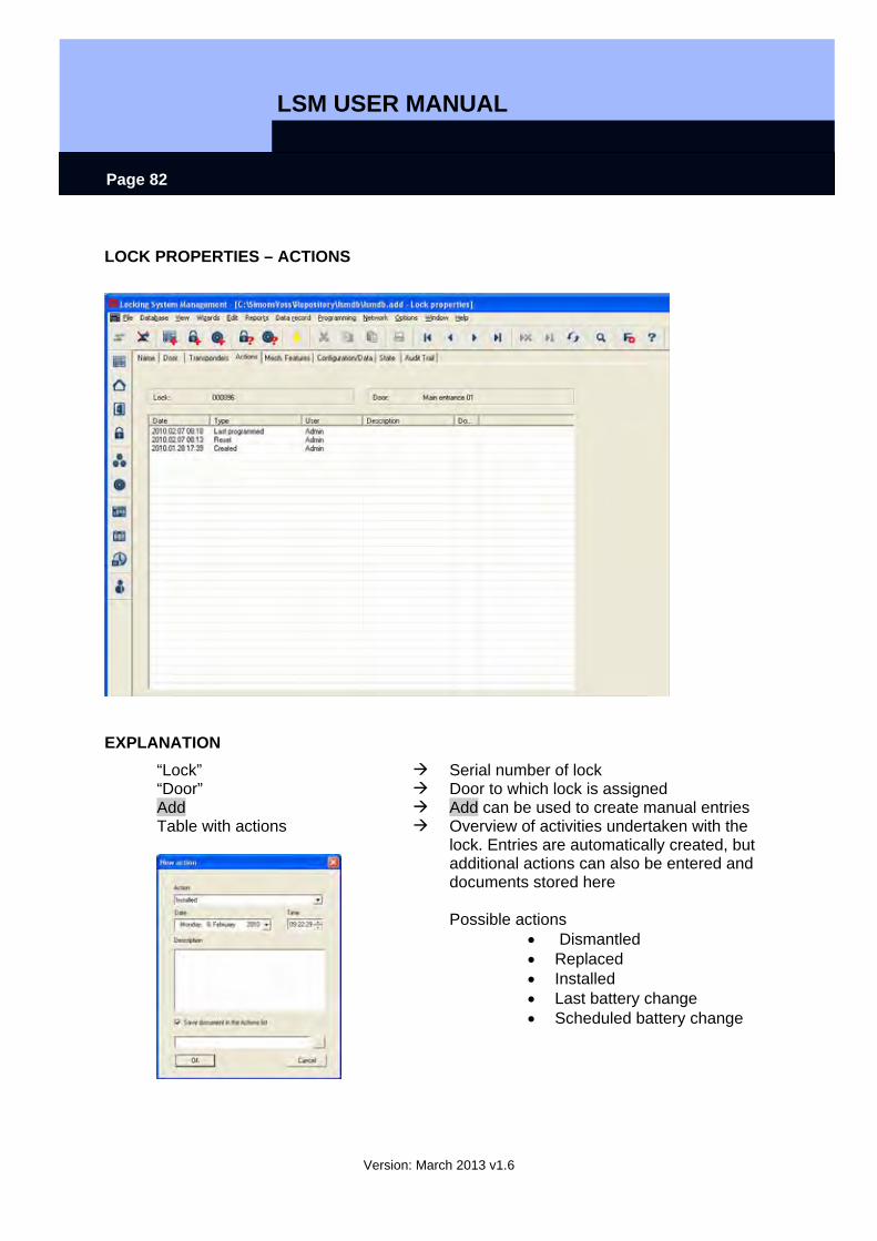
LOCK PROPERTIES – ACTIONS
EXPLANATION “Lock” Serial number of lock “Door” Door to which lock is assigned Add Add can be used to create manual entries Table with actions
Overview of activities undertaken with the lock. Entries are automatically created, but additional actions can also be entered and documents stored here Possible actions
• Dismantled • Replaced • Installed • Last battery change • Scheduled battery change

LSM USER MANUAL
Version: March 2013 v1.6
Page 83
LOCK PROPERTIES – G1 FITTINGS
EXPLANATION “Lock” Serial number of lock “Door” Door to which lock is assigned “Product” Product group “Serial number” Serial number read during programming Attributes for locking cylinders Are automatically read and entered into a
workstation the first time a lock is programmed
Use The attributes that were entered manually in the door are adopted
“Knobs” Information on type of knobs Data Device class Product class of lock PHI Public Hardware Identifier, hardware
identification Profile release Internal counter to manage the
programming processes

LSM USER MANUAL
Version: March 2013 v1.6
Page 84
LOCK PROPERTIES – G2 FITTINGS
EXPLANATION “Lock” Serial number of lock “Door” Door to which lock is assigned “Product” Product group “Serial number” Serial number read during programming Attributes for locking cylinders Are automatically read and entered into a
workstation the first time a lock is programmed
Use The attributes that were entered manually in the door are adopted
“Knobs” Information on type of knobs Data Device class Product class of lock PHI Public Hardware Identifier, hardware
identification Profile release Internal counter to manage the
programming processes
LSM USER MANUAL
Version: March 2013 v1.6
Page 85
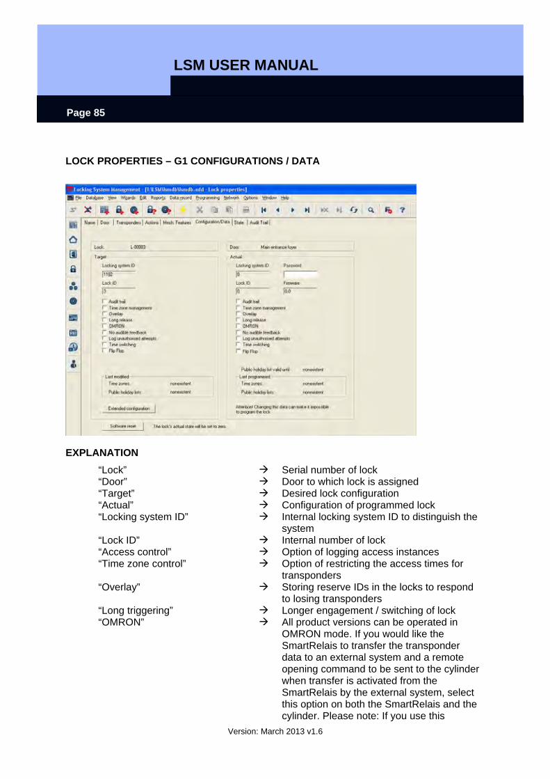
LOCK PROPERTIES – G1 CONFIGURATIONS / DATA
EXPLANATION “Lock” Serial number of lock “Door” Door to which lock is assigned “Target” Desired lock configuration “Actual” Configuration of programmed lock “Locking system ID” Internal locking system ID to distinguish the
system “Lock ID” Internal number of lock “Access control” Option of logging access instances “Time zone control” Option of restricting the access times for
transponders “Overlay” Storing reserve IDs in the locks to respond
to losing transponders “Long triggering” Longer engagement / switching of lock “OMRON” All product versions can be operated in
OMRON mode. If you would like the SmartRelais to transfer the transponder data to an external system and a remote opening command to be sent to the cylinder when transfer is activated from the SmartRelais by the external system, select this option on both the SmartRelais and the cylinder. Please note: If you use this
LSM USER MANUAL
Version: March 2013 v1.6
Page 86
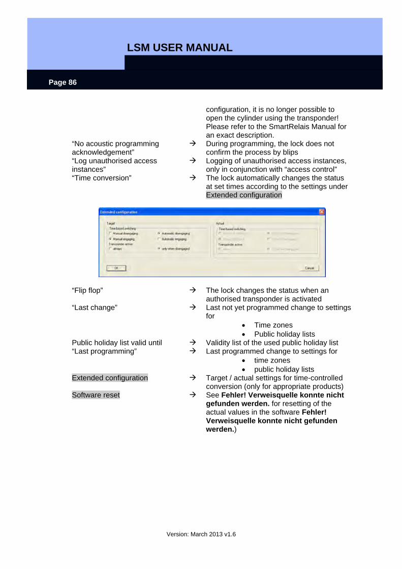
configuration, it is no longer possible to open the cylinder using the transponder! Please refer to the SmartRelais Manual for an exact description.
“No acoustic programming acknowledgement”
During programming, the lock does not confirm the process by blips
“Log unauthorised access instances”
Logging of unauthorised access instances, only in conjunction with “access control”
“Time conversion” The lock automatically changes the status at set times according to the settings under Extended configuration
“Flip flop” The lock changes the status when an authorised transponder is activated
“Last change” Last not yet programmed change to settings for
• Time zones • Public holiday lists
Public holiday list valid until Validity list of the used public holiday list “Last programming” Last programmed change to settings for
• time zones • public holiday lists
Extended configuration Target / actual settings for time-controlled conversion (only for appropriate products)
Software reset See Fehler! Verweisquelle konnte nicht gefunden werden. for resetting of the actual values in the software Fehler! Verweisquelle konnte nicht gefunden werden.)
LSM USER MANUAL
Version: March 2013 v1.6
Page 87
LOCK PROPERTIES – G2 CONFIGURATIONS / DATA
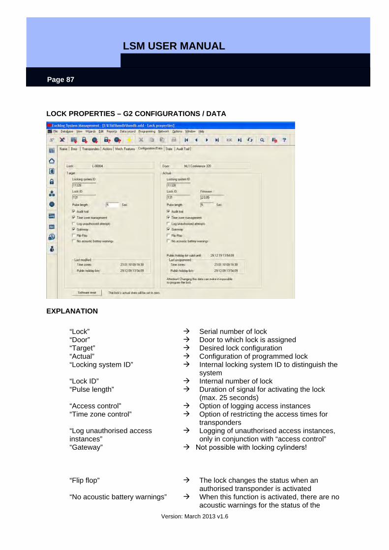
EXPLANATION
“Lock” Serial number of lock “Door” Door to which lock is assigned “Target” Desired lock configuration “Actual” Configuration of programmed lock “Locking system ID” Internal locking system ID to distinguish the
system “Lock ID” Internal number of lock “Pulse length” Duration of signal for activating the lock
(max. 25 seconds) “Access control” Option of logging access instances “Time zone control” Option of restricting the access times for
transponders “Log unauthorised access instances”
Logging of unauthorised access instances,
“Gateway” only in conjunction with “access control”
Not possible with locking cylinders!
“Flip flop” The lock changes the status when an authorised transponder is activated
“No acoustic battery warnings” When this function is activated, there are no acoustic warnings for the status of the
LSM USER MANUAL
Version: March 2013 v1.6
Page 88
battery in the components “Last change” Last not yet programmed change to settings
for • Time zones • Public holiday lists
Public holiday list valid until Validity list of the used public holiday list “Last programming” Last programmed change to settings for
• time zones • public holiday lists
Monitoring configuration Software reset
Launch of the menu to configure the Door Monitoring Cylinder See Fehler! Verweisquelle konnte nicht gefunden werden. for resetting of the actual values in the software Fehler! Verweisquelle konnte nicht gefunden werden.)
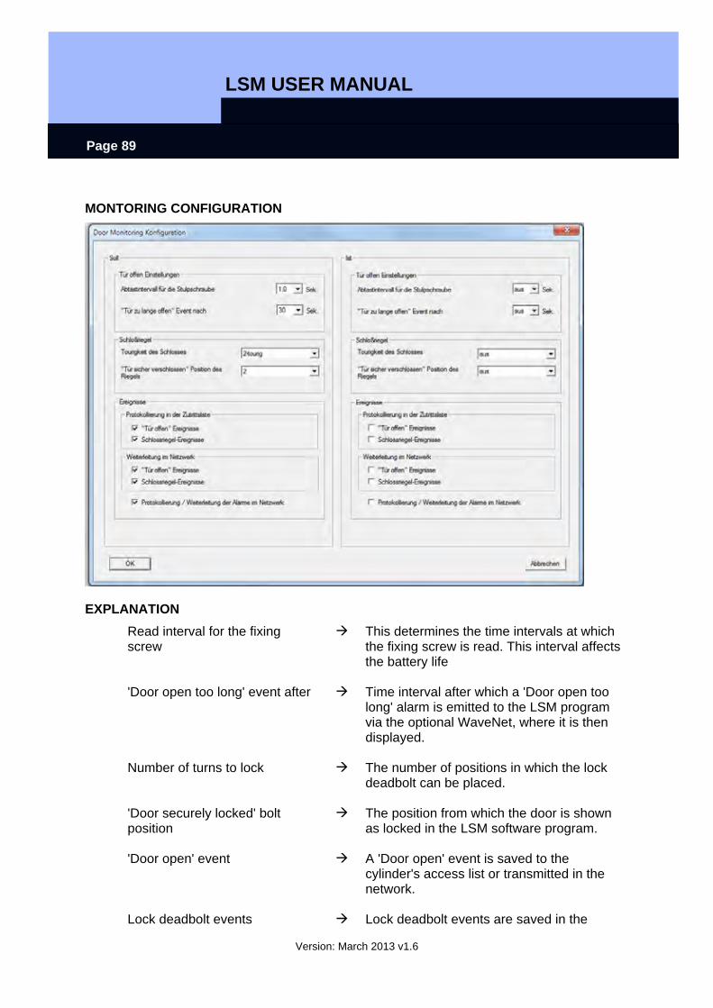
LSM USER MANUAL
Version: March 2013 v1.6
Page 89
MONTORING CONFIGURATION
EXPLANATION Read interval for the fixing screw
This determines the time intervals at which the fixing screw is read. This interval affects the battery life
'Door open too long' event after Time interval after which a 'Door open too long' alarm is emitted to the LSM program via the optional WaveNet, where it is then displayed.
Number of turns to lock The number of positions in which the lock deadbolt can be placed.
'Door securely locked' bolt position
The position from which the door is shown as locked in the LSM software program.
'Door open' event A 'Door open' event is saved to the cylinder's access list or transmitted in the network.
Lock deadbolt events Lock deadbolt events are saved in the
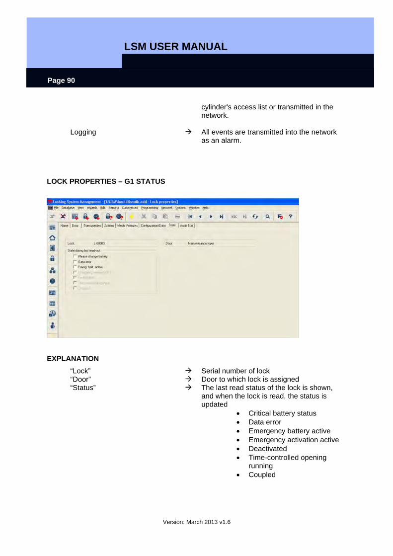
LSM USER MANUAL
Version: March 2013 v1.6
Page 90
cylinder's access list or transmitted in the network.
Logging All events are transmitted into the network as an alarm.
LOCK PROPERTIES – G1 STATUS
EXPLANATION “Lock” Serial number of lock “Door” Door to which lock is assigned “Status” The last read status of the lock is shown,
and when the lock is read, the status is updated
• Critical battery status • Data error • Emergency battery active • Emergency activation active • Deactivated • Time-controlled opening
running • Coupled
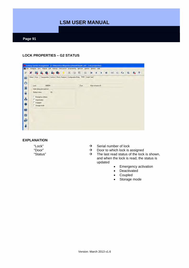
LSM USER MANUAL
Version: March 2013 v1.6
Page 91
LOCK PROPERTIES – G2 STATUS
EXPLANATION “Lock” Serial number of lock “Door” Door to which lock is assigned “Status” The last read status of the lock is shown,
and when the lock is read, the status is updated
• Emergency activation • Deactivated • Coupled • Storage mode
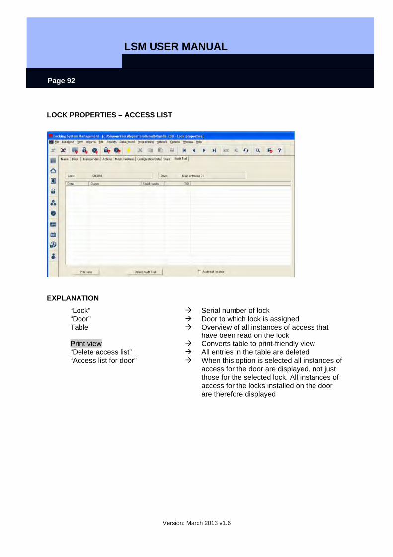
LSM USER MANUAL
Version: March 2013 v1.6
Page 92
LOCK PROPERTIES – ACCESS LIST
EXPLANATION “Lock” Serial number of lock “Door” Door to which lock is assigned Table Overview of all instances of access that
have been read on the lock Print view Converts table to print-friendly view “Delete access list” All entries in the table are deleted “Access list for door” When this option is selected all instances of
access for the door are displayed, not just those for the selected lock. All instances of access for the locks installed on the door are therefore displayed
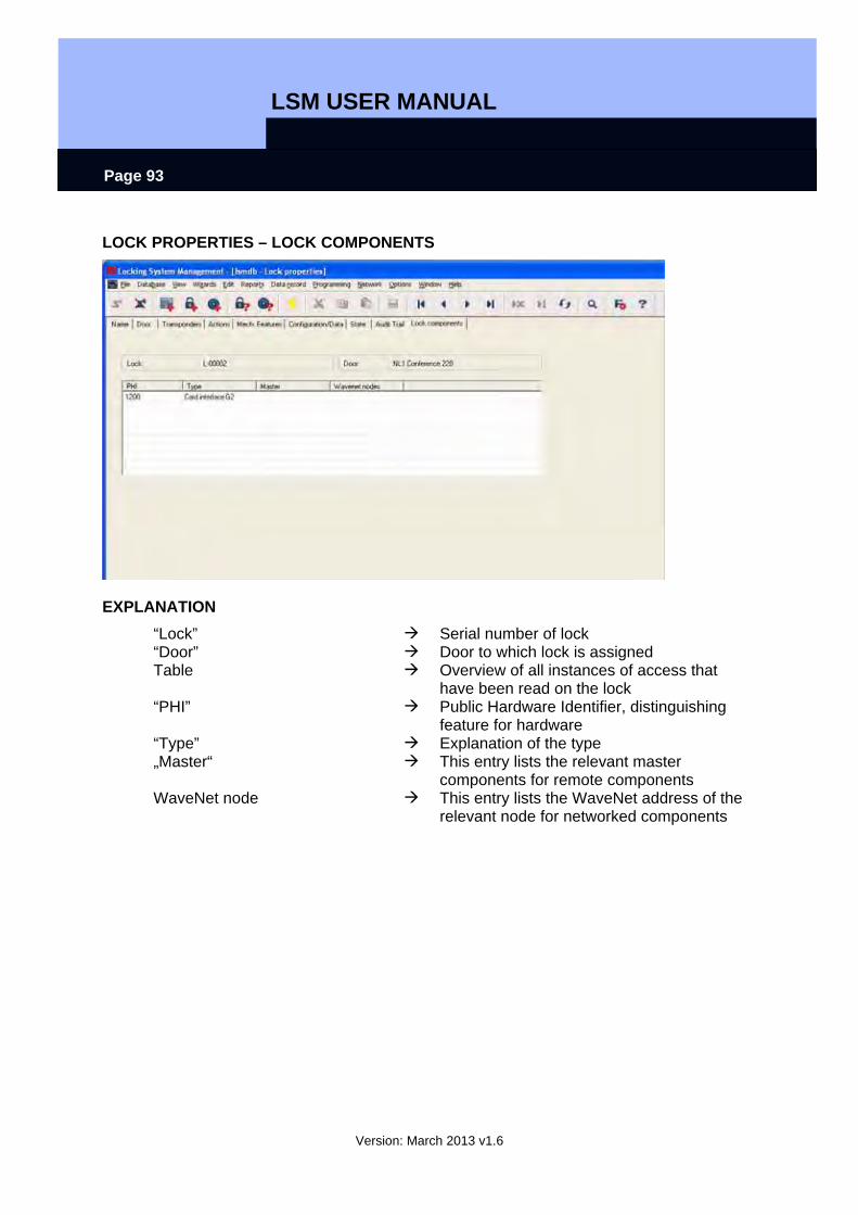
LSM USER MANUAL
Version: March 2013 v1.6
Page 93
LOCK PROPERTIES – LOCK COMPONENTS
EXPLANATION “Lock” Serial number of lock “Door” Door to which lock is assigned Table Overview of all instances of access that
have been read on the lock “PHI” Public Hardware Identifier, distinguishing
feature for hardware “Type” Explanation of the type „Master“ This entry lists the relevant master
components for remote components WaveNet node This entry lists the WaveNet address of the
relevant node for networked components
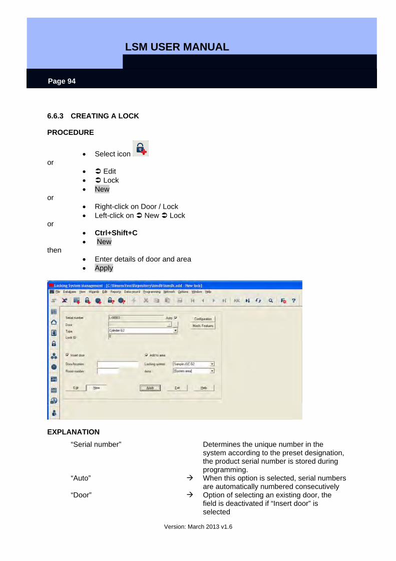
LSM USER MANUAL
Version: March 2013 v1.6
Page 94
6.6.3 CREATING A LOCK
PROCEDURE
• Select icon or
• Edit • Lock • New
or • Right-click on Door / Lock • Left-click on New Lock
or • Ctrl+Shift+C • New
then • Enter details of door and area • Apply
EXPLANATION “Serial number” Determines the unique number in the
system according to the preset designation, the product serial number is stored during programming.
“Auto” When this option is selected, serial numbers are automatically numbered consecutively
“Door” Option of selecting an existing door, the field is deactivated if “Insert door” is selected
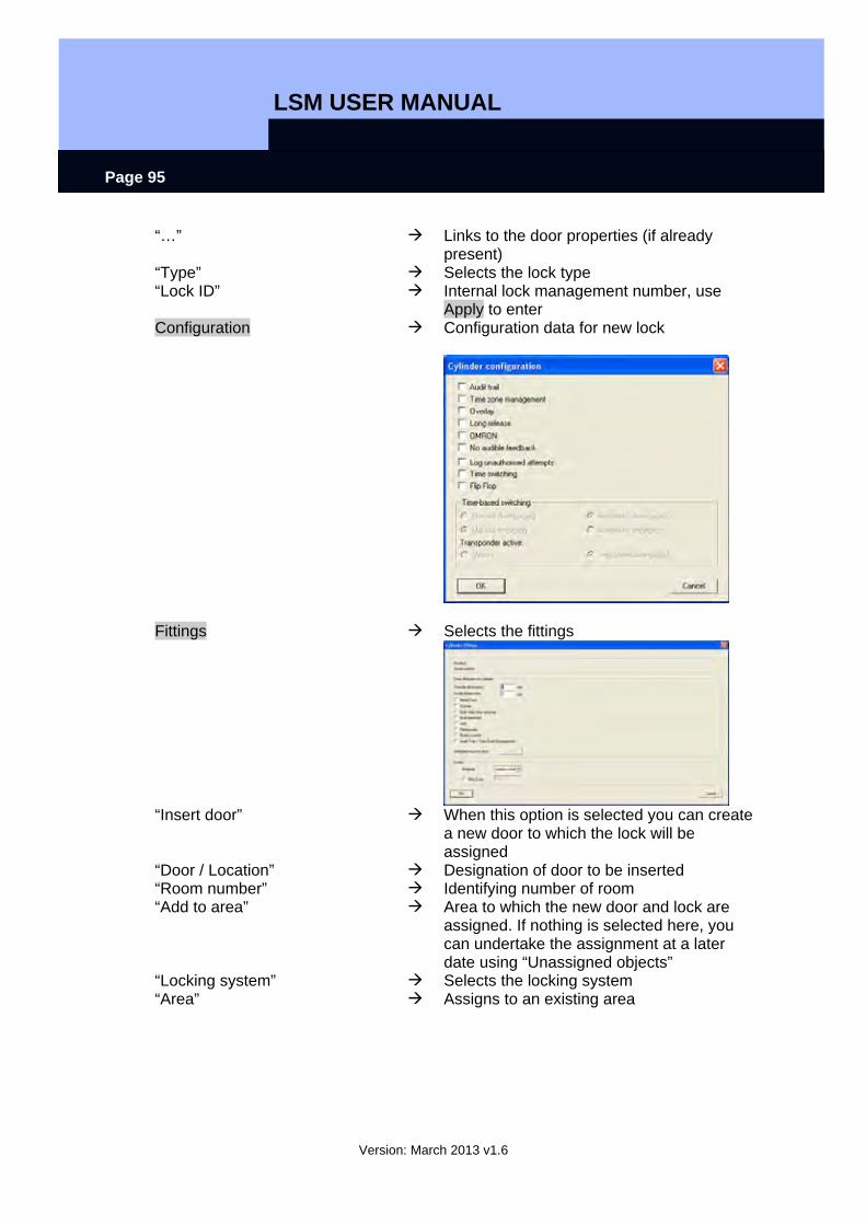
LSM USER MANUAL
Version: March 2013 v1.6
Page 95
“…” Links to the door properties (if already present)
“Type” Selects the lock type “Lock ID” Internal lock management number, use
Apply to enter Configuration Configuration data for new lock
Fittings Selects the fittings
“Insert door” When this option is selected you can create
a new door to which the lock will be assigned
“Door / Location” Designation of door to be inserted “Room number” Identifying number of room “Add to area” Area to which the new door and lock are
assigned. If nothing is selected here, you can undertake the assignment at a later date using “Unassigned objects”
“Locking system” Selects the locking system “Area” Assigns to an existing area
LSM USER MANUAL
Version: March 2013 v1.6
Page 96
6.6.4 EDITING A LOCK
PROCEDURE
ICON
EXPLANATION SimonsVoss describes as “locks” all products that can be operated with a transponder. This includes SmartRelais, activation units and locking cylinders, for example.
PROCEDURE
• Select icon • Select area using arrow buttons
or • Edit • Lock properties • Select lock using arrow buttons
or • Select the lock you want to modify in the matrix • Right-click on the door / lock • Properties • Lock
or • Right-click on any lock in the matrix • Search • Select object • Enter designation or part of designation you want to search for • Search • Highlight the data record you want in the result set • Select properties in “Navigation to view” • Click on Execute to go to the lock overview
or • Right-click on the door / lock • Properties • Lock
then • Modify data • Apply
LSM USER MANUAL
Version: March 2013 v1.6
Page 97
6.7. DOORS
6.7.1 GENERAL CORRECTIONS FOR DOORS
ICON
EXPLANATION A door is the assigned installation site for one or more locks. It is possible to store additional parameters such as description of lock, floor and building.
PROCEDURE
• Select icon • Select area using arrow buttons
or • Edit • Door • Select door using arrow buttons
or • Right-click on the door / lock • Properties • Door
or • Ctrl+Shift+D

LSM USER MANUAL
Version: March 2013 v1.6
Page 98
EXPLANATION “Door designation” Name of door “Location” Location in which the building can be found
(must be created first) “Building” Building in which door is located (must be
created first) “Floor” Floor on which door is located (can be
created by inputting text) “Room number” Room number of door “Description” Free field for describing the door “Locks” Locks assigned to the door Assignment to areas Manage Option of removing a door or assigning it to
a particular area Programming device “Type” Selection of programming device type
(config device, LockNode, WaveNet node) “Device” Selection of a particular device, mainly
required for LON and WaveNet “Unassigned devices” When this option is selected, otherwise
assigned LON and WaveNet nodes are no longer displayed
“Door attributes for mortise lock”
Additional data is shown for the mortise lock
“Door attributes for locking cylinder”
Additional data can be specified for the locking cylinder

LSM USER MANUAL
Version: March 2013 v1.6
Page 99
6.7.2 EDIT DOOR
PROCEDURE
• Select icon • Select area using arrow buttons
or • Edit • Door • Select door using arrow buttons
or • Select the door you want to modify in the matrix • Right-click on Door • Properties • Door
or • Right-click on any door in the matrix • Search • Select object • Enter designation or part of designation you want to search for • Search • Highlight the data record you want in the result set • Select properties in “Navigation to view” • Click on Execute to go to the door overview
or • Right-click on the door • Properties • Door
then • Modify data • Apply
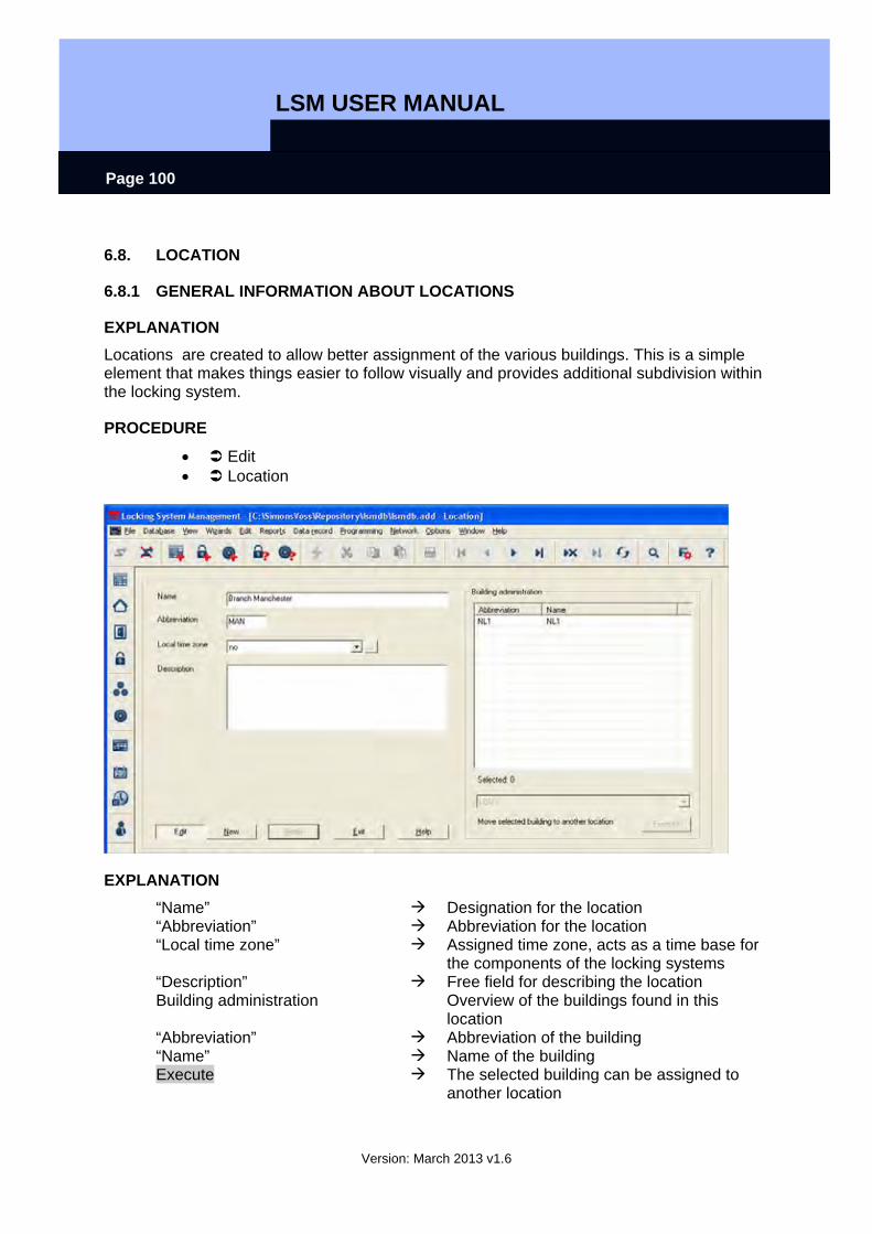
LSM USER MANUAL
Version: March 2013 v1.6
Page 100
6.8. LOCATION
6.8.1 GENERAL INFORMATION ABOUT LOCATIONS
EXPLANATION Locations are created to allow better assignment of the various buildings. This is a simple element that makes things easier to follow visually and provides additional subdivision within the locking system.
PROCEDURE
• Edit • Location
EXPLANATION “Name” Designation for the location “Abbreviation” Abbreviation for the location “Local time zone” Assigned time zone, acts as a time base for
the components of the locking systems “Description” Free field for describing the location Building administration Overview of the buildings found in this
location “Abbreviation” Abbreviation of the building “Name” Name of the building Execute The selected building can be assigned to
another location
LSM USER MANUAL
Version: March 2013 v1.6
Page 101
6.8.2 CREATE LOCATION
• Edit • Location • New • Enter data • Apply
6.8.3 EDIT LOCATION
• Edit • Location • Select location using arrow buttons • Modify data • Apply
NOTE When exported to the pocket PC and in the matrix, building structures are shown using the additional columns (see 1.5.2 Additional columns in label bars).
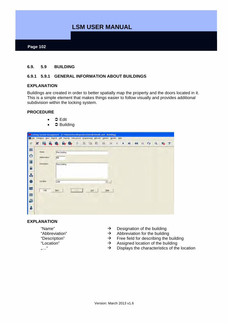
LSM USER MANUAL
Version: March 2013 v1.6
Page 102
6.9. 5.9 BUILDING
6.9.1 5.9.1 GENERAL INFORMATION ABOUT BUILDINGS
EXPLANATION Buildings are created in order to better spatially map the property and the doors located in it. This is a simple element that makes things easier to follow visually and provides additional subdivision within the locking system.
PROCEDURE
• Edit • Building
EXPLANATION “Name” Designation of the building “Abbreviation” Abbreviation for the building “Description” Free field for describing the building “Location” Assigned location of the building „…“ Displays the characteristics of the location
LSM USER MANUAL
Version: March 2013 v1.6
Page 103
6.9.2 5.9.2 CREATE BUILDING
• Edit • Building • New • Enter data • Apply
6.9.3 5.9.3 EDIT BUILDING
• Edit • Building • Modify data • Apply
NOTE When exported to the pocket PC and in the matrix, building structures are shown using the additional columns (see 1.5.2 Additional columns in label bars).

LSM USER MANUAL
Version: March 2013 v1.6
Page 104
7.0 WIZARDS The wizards available in the system guide the user through the process of creating doors with locks and persons with transponders. All the information which is relevant to the system is queried as you work through the various input screens so that the components can be created properly. This assists inexperienced users as they become familiar with the system in order to learn about the information that is relevant to the system. Professionals too will value this as a tool which allows them to create new components quickly and without forgetting important information even when under pressure.
EXPLANATION A door is the assigned installation site for one or more locks. It is possible to store additional parameters such as description of lock, floor and building. The locks are stored on the doors. SimonsVoss describes as “locks” all products that can be operated with a transponder. This includes SmartRelais, activation units and locking cylinders, for example. It is also possible to create the associated lock when using the door wizard.
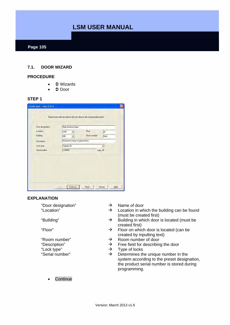
LSM USER MANUAL
Version: March 2013 v1.6
Page 105
7.1. DOOR WIZARD
PROCEDURE
• Wizards • Door
STEP 1
EXPLANATION “Door designation” Name of door “Location” Location in which the building can be found
(must be created first) “Building” Building in which door is located (must be
created first) “Floor” Floor on which door is located (can be
created by inputting text) “Room number” Room number of door “Description” Free field for describing the door “Lock type” Type of locks “Serial number” Determines the unique number in the
system according to the preset designation, the product serial number is stored during programming.
• Continue
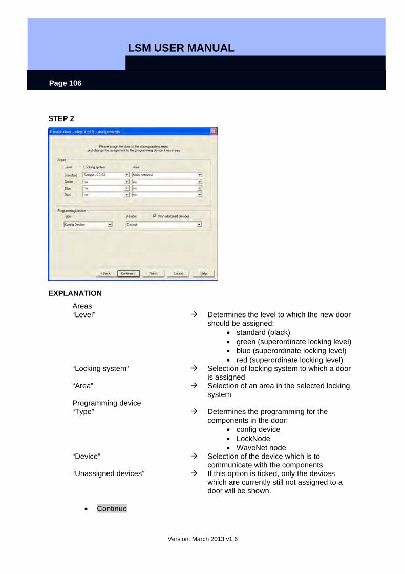
LSM USER MANUAL
Version: March 2013 v1.6
Page 106
STEP 2
EXPLANATION Areas “Level” Determines the level to which the new door
should be assigned: • standard (black) • green (superordinate locking level) • blue (superordinate locking level) • red (superordinate locking level)
“Locking system” Selection of locking system to which a door is assigned
“Area” Selection of an area in the selected locking system
Programming device “Type” Determines the programming for the
components in the door: • config device • LockNode • WaveNet node
“Device” Selection of the device which is to communicate with the components
“Unassigned devices” If this option is ticked, only the devices which are currently still not assigned to a door will be shown.
• Continue
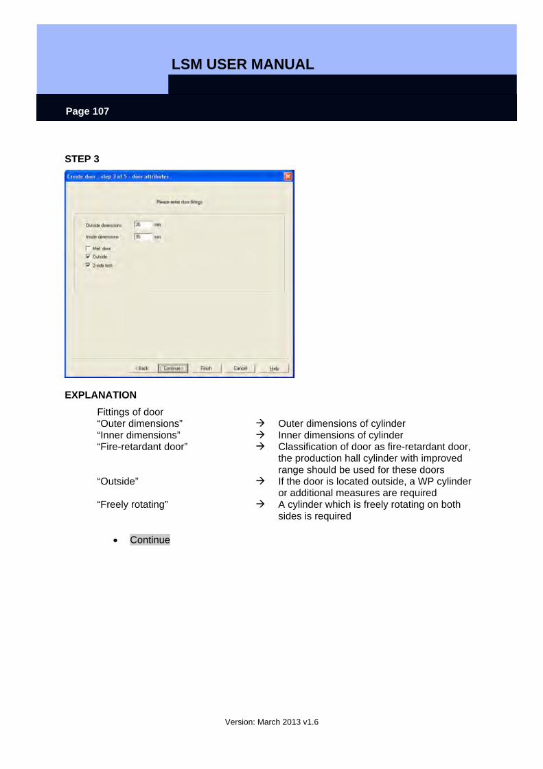
LSM USER MANUAL
Version: March 2013 v1.6
Page 107
STEP 3
EXPLANATION Fittings of door “Outer dimensions” Outer dimensions of cylinder “Inner dimensions” Inner dimensions of cylinder “Fire-retardant door” Classification of door as fire-retardant door,
the production hall cylinder with improved range should be used for these doors
“Outside” If the door is located outside, a WP cylinder or additional measures are required
“Freely rotating” A cylinder which is freely rotating on both sides is required
• Continue
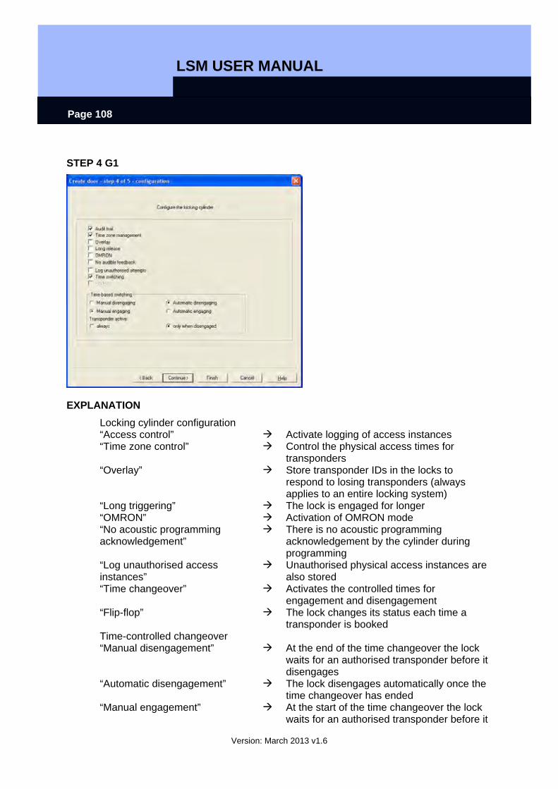
LSM USER MANUAL
Version: March 2013 v1.6
Page 108
STEP 4 G1
EXPLANATION Locking cylinder configuration “Access control” Activate logging of access instances “Time zone control” Control the physical access times for
transponders “Overlay” Store transponder IDs in the locks to
respond to losing transponders (always applies to an entire locking system)
“Long triggering” The lock is engaged for longer “OMRON” Activation of OMRON mode “No acoustic programming acknowledgement”
There is no acoustic programming acknowledgement by the cylinder during programming
“Log unauthorised access instances”
Unauthorised physical access instances are also stored
“Time changeover” Activates the controlled times for engagement and disengagement
“Flip-flop” The lock changes its status each time a transponder is booked
Time-controlled changeover “Manual disengagement” At the end of the time changeover the lock
waits for an authorised transponder before it disengages
“Automatic disengagement” The lock disengages automatically once the time changeover has ended
“Manual engagement” At the start of the time changeover the lock waits for an authorised transponder before it
LSM USER MANUAL
Version: March 2013 v1.6
Page 109
engages “Automatic engagement” The lock engages automatically once the
time changeover has started “Transponder active” “Always” The transponder can always change the
status of the lock “Only when disengaged” The transponder can only change the status
of the lock when it is not permanently engaged (normal physical access)
• Continue
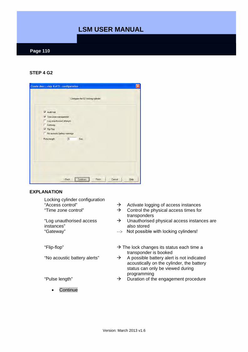
LSM USER MANUAL
Version: March 2013 v1.6
Page 110
STEP 4 G2
EXPLANATION Locking cylinder configuration “Access control” Activate logging of access instances “Time zone control” Control the physical access times for
transponders “Log unauthorised access instances”
Unauthorised physical access instances are
“Gateway” also stored
--> Not possible with locking cylinders!
“Flip-flop” The lock changes its status each time a transponder is booked
“No acoustic battery alerts” A possible battery alert is not indicated acoustically on the cylinder, the battery status can only be viewed during programming
“Pulse length” Duration of the engagement procedure
• Continue
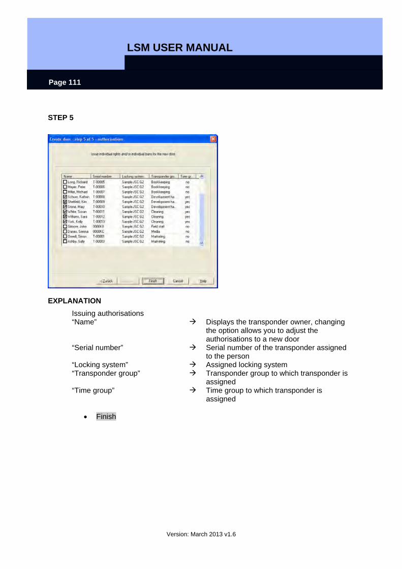
LSM USER MANUAL
Version: March 2013 v1.6
Page 111
STEP 5
EXPLANATION Issuing authorisations “Name” Displays the transponder owner, changing
the option allows you to adjust the authorisations to a new door
“Serial number” Serial number of the transponder assigned to the person
“Locking system” Assigned locking system “Transponder group” Transponder group to which transponder is
assigned “Time group” Time group to which transponder is
assigned
• Finish
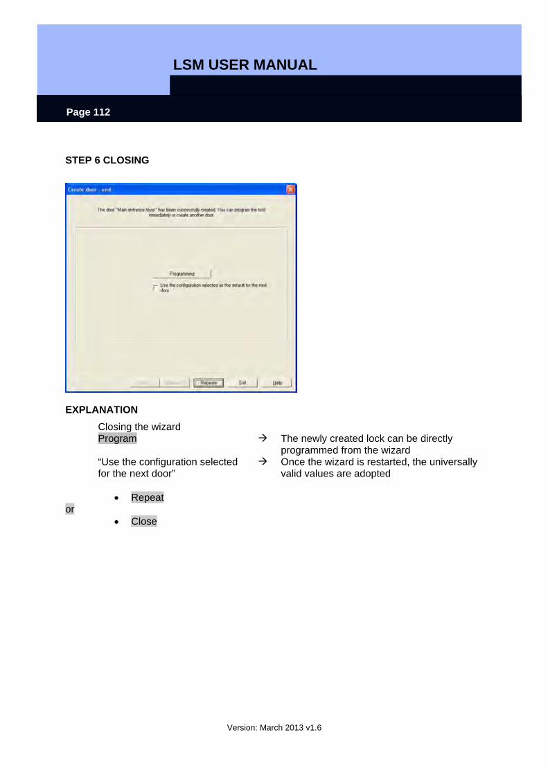
LSM USER MANUAL
Version: March 2013 v1.6
Page 112
STEP 6 CLOSING
EXPLANATION Closing the wizard Program The newly created lock can be directly
programmed from the wizard “Use the configuration selected for the next door”
Once the wizard is restarted, the universally valid values are adopted
• Repeat
or • Close
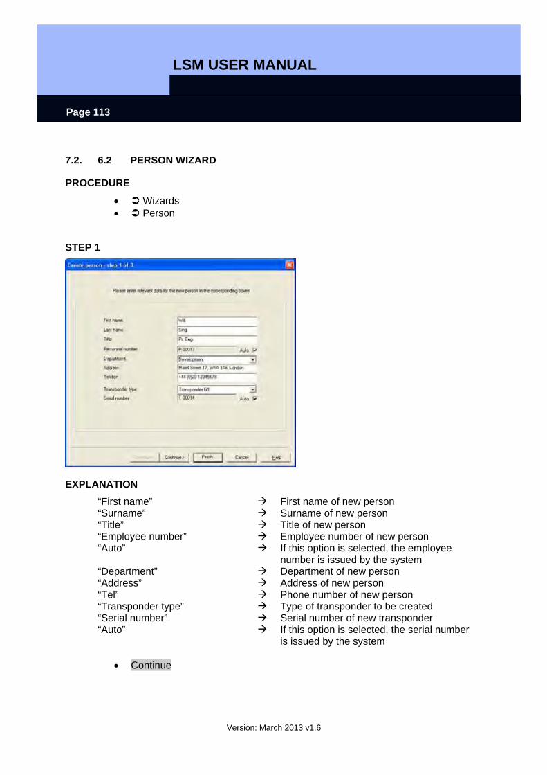
LSM USER MANUAL
Version: March 2013 v1.6
Page 113
7.2. 6.2 PERSON WIZARD
PROCEDURE
• Wizards • Person
STEP 1
EXPLANATION “First name” First name of new person “Surname” Surname of new person “Title” Title of new person “Employee number” Employee number of new person “Auto” If this option is selected, the employee
number is issued by the system “Department” Department of new person “Address” Address of new person “Tel” Phone number of new person “Transponder type” Type of transponder to be created “Serial number” Serial number of new transponder “Auto” If this option is selected, the serial number
is issued by the system
• Continue
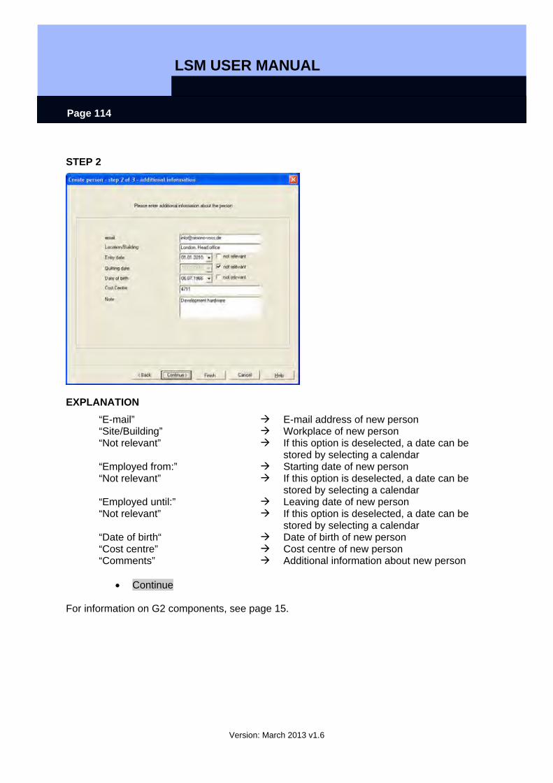
LSM USER MANUAL
Version: March 2013 v1.6
Page 114
STEP 2
EXPLANATION “E-mail” E-mail address of new person “Site/Building” Workplace of new person “Not relevant” If this option is deselected, a date can be
stored by selecting a calendar “Employed from:” Starting date of new person “Not relevant” If this option is deselected, a date can be
stored by selecting a calendar “Employed until:” Leaving date of new person “Not relevant” If this option is deselected, a date can be
stored by selecting a calendar “Date of birth“ Date of birth of new person “Cost centre” Cost centre of new person “Comments” Additional information about new person
• Continue
For information on G2 components, see page 15.
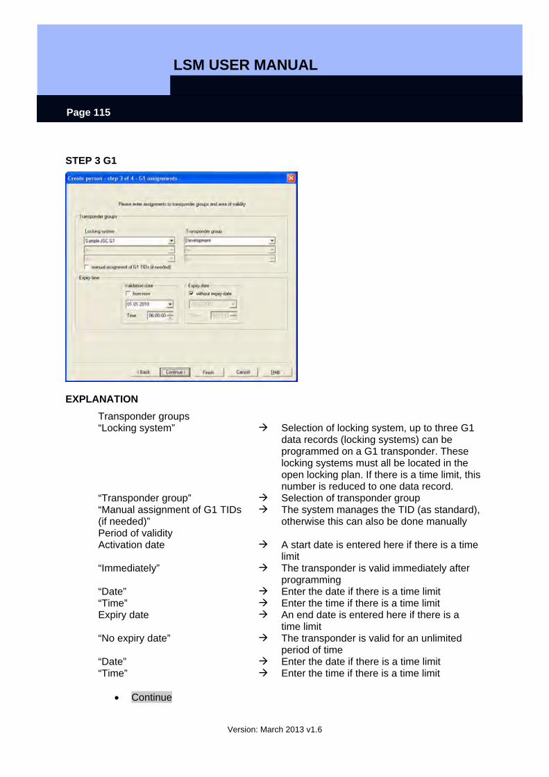
LSM USER MANUAL
Version: March 2013 v1.6
Page 115
STEP 3 G1
EXPLANATION Transponder groups “Locking system” Selection of locking system, up to three G1
data records (locking systems) can be programmed on a G1 transponder. These locking systems must all be located in the open locking plan. If there is a time limit, this number is reduced to one data record.
“Transponder group” Selection of transponder group “Manual assignment of G1 TIDs (if needed)”
The system manages the TID (as standard), otherwise this can also be done manually
Period of validity Activation date A start date is entered here if there is a time
limit “Immediately” The transponder is valid immediately after
programming “Date” Enter the date if there is a time limit “Time” Enter the time if there is a time limit Expiry date An end date is entered here if there is a
time limit “No expiry date” The transponder is valid for an unlimited
period of time “Date” Enter the date if there is a time limit “Time” Enter the time if there is a time limit
• Continue
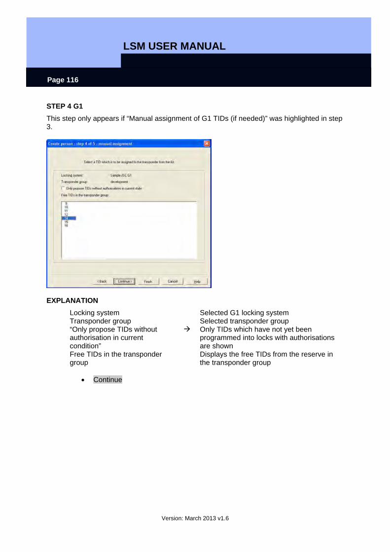
LSM USER MANUAL
Version: March 2013 v1.6
Page 116
STEP 4 G1 This step only appears if “Manual assignment of G1 TIDs (if needed)” was highlighted in step 3.
EXPLANATION Locking system Selected G1 locking system Transponder group Selected transponder group “Only propose TIDs without authorisation in current condition”
Only TIDs which have not yet been programmed into locks with authorisations are shown
Free TIDs in the transponder group
Displays the free TIDs from the reserve in the transponder group
• Continue
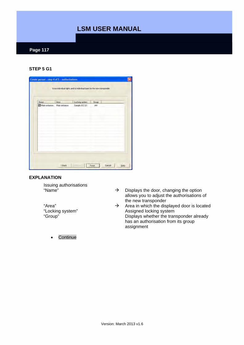
LSM USER MANUAL
Version: March 2013 v1.6
Page 117
STEP 5 G1
EXPLANATION Issuing authorisations “Name” Displays the door, changing the option
allows you to adjust the authorisations of the new transponder
“Area” Area in which the displayed door is located “Locking system” Assigned locking system “Group” Displays whether the transponder already
has an authorisation from its group assignment
• Continue
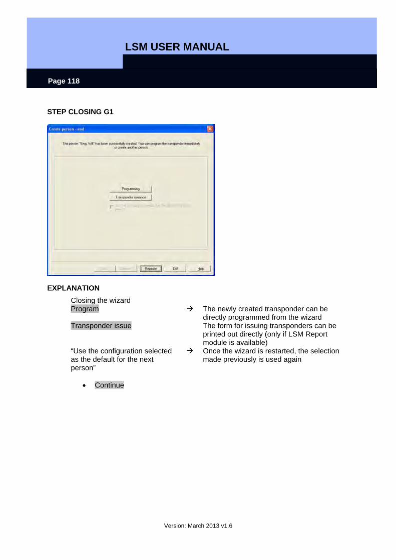
LSM USER MANUAL
Version: March 2013 v1.6
Page 118
STEP CLOSING G1
EXPLANATION Closing the wizard Program The newly created transponder can be
directly programmed from the wizard Transponder issue The form for issuing transponders can be
printed out directly (only if LSM Report module is available)
“Use the configuration selected as the default for the next person”
Once the wizard is restarted, the selection made previously is used again
• Continue

LSM USER MANUAL
Version: March 2013 v1.6
Page 119
STEP 3 G2
EXPLANATION Transponder groups G2/G2+G1 “Locking system” Selection of locking system, up to four G2
data records (locking systems) can be programmed on a G2 transponder. These locking systems must however all be located in the open locking plan.
“Transponder group” Selection of transponder group “G1” In a mixed locking system (G2+G1), TIDs
from the lower 8000 block can also be used in compatibility with G1 locks by ticking the option
“Manual assignment of G1 TIDs (if needed)”
The system manages the TID used for G1 otherwise issuing can take place manually
G1 “Locking system” Selection of locking system, up to three G1
data records (locking systems) can be programmed on a G1 transponder. These locking systems must however all be located in the open locking plan.
“Transponder group” Selection of transponder group
• Continue
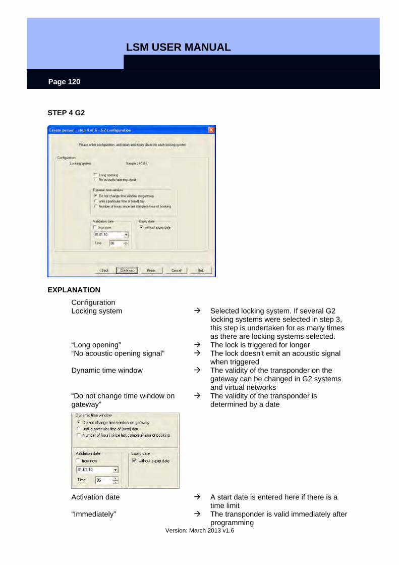
LSM USER MANUAL
Version: March 2013 v1.6
Page 120
STEP 4 G2
EXPLANATION Configuration Locking system Selected locking system. If several G2
locking systems were selected in step 3, this step is undertaken for as many times as there are locking systems selected.
“Long opening” The lock is triggered for longer “No acoustic opening signal” The lock doesn't emit an acoustic signal
when triggered Dynamic time window The validity of the transponder on the
gateway can be changed in G2 systems and virtual networks
“Do not change time window on gateway”
The validity of the transponder is determined by a date
Activation date A start date is entered here if there is a time limit
“Immediately” The transponder is valid immediately after programming
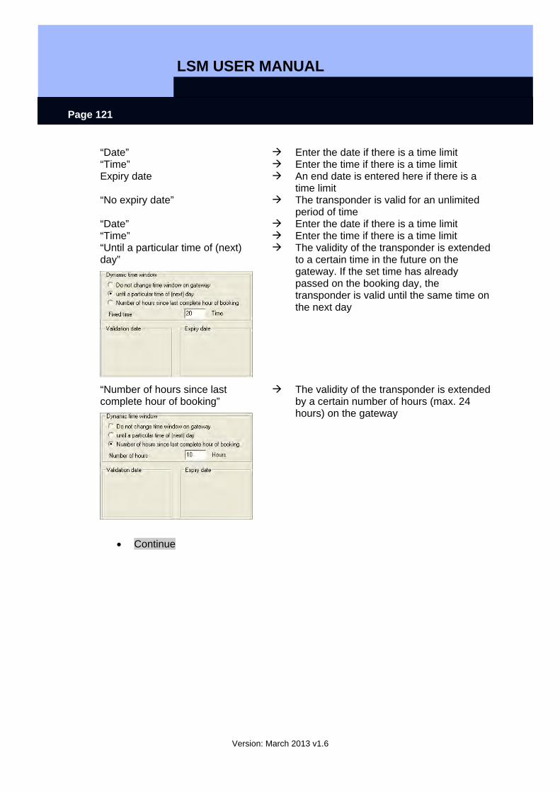
LSM USER MANUAL
Version: March 2013 v1.6
Page 121
“Date” Enter the date if there is a time limit “Time” Enter the time if there is a time limit Expiry date An end date is entered here if there is a
time limit “No expiry date” The transponder is valid for an unlimited
period of time “Date” Enter the date if there is a time limit “Time” Enter the time if there is a time limit “Until a particular time of (next) day”
The validity of the transponder is extended to a certain time in the future on the gateway. If the set time has already passed on the booking day, the transponder is valid until the same time on the next day
“Number of hours since last complete hour of booking”
The validity of the transponder is extended by a certain number of hours (max. 24 hours) on the gateway
• Continue
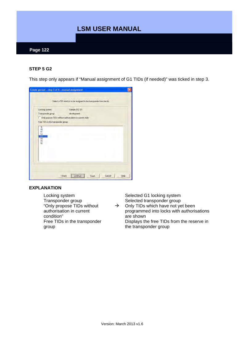
LSM USER MANUAL
Version: March 2013 v1.6
Page 122
STEP 5 G2 This step only appears if “Manual assignment of G1 TIDs (if needed)” was ticked in step 3.
EXPLANATION Locking system Selected G1 locking system Transponder group Selected transponder group “Only propose TIDs without authorisation in current condition”
Only TIDs which have not yet been programmed into locks with authorisations are shown
Free TIDs in the transponder group
Displays the free TIDs from the reserve in the transponder group

LSM USER MANUAL
Version: March 2013 v1.6
Page 123
STEP 6 G2
EXPLANATION Issuing authorisations “Name” Displays the door, changing the option
allows you to adjust the authorisations of the new transponder
“Area” Area in which the displayed door is located “Locking system” Assigned locking system “Group” Displays whether the transponder already
has an authorisation from its group assignment

LSM USER MANUAL
Version: March 2013 v1.6
Page 124
STEP CLOSING G2
EXPLANATION Closing the wizard Program The newly created transponder can be
directly programmed from the wizard Transponder issue The form for issuing transponders can be
printed out directly (only if LSM Report module is available)
“Use the configuration selected as the default for the next person”
Once the wizard is restarted, the selection made previously is used again
• Continue
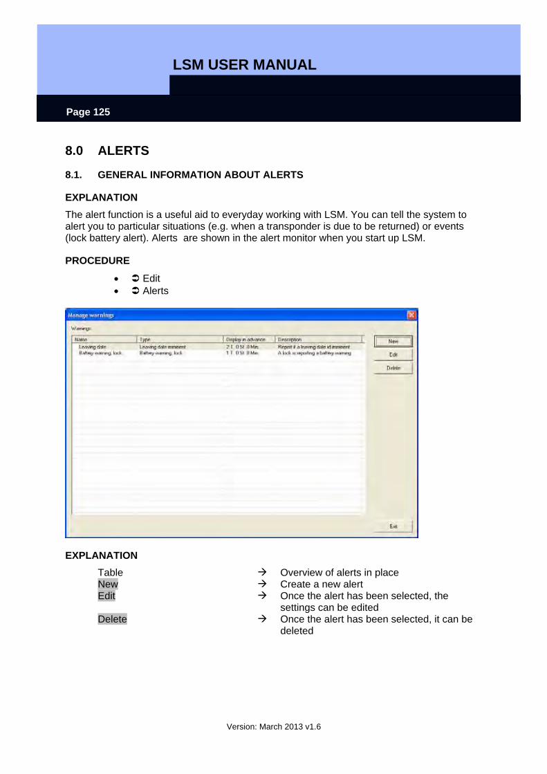
LSM USER MANUAL
Version: March 2013 v1.6
Page 125
8.0 ALERTS
8.1. GENERAL INFORMATION ABOUT ALERTS
EXPLANATION The alert function is a useful aid to everyday working with LSM. You can tell the system to alert you to particular situations (e.g. when a transponder is due to be returned) or events (lock battery alert). Alerts are shown in the alert monitor when you start up LSM.
PROCEDURE
• Edit • Alerts
EXPLANATION Table Overview of alerts in place New Create a new alert Edit Once the alert has been selected, the
settings can be edited Delete Once the alert has been selected, it can be
deleted
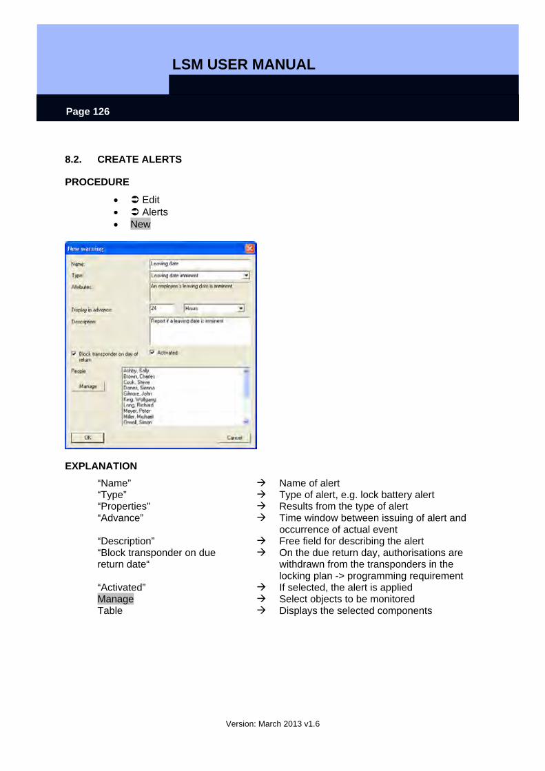
LSM USER MANUAL
Version: March 2013 v1.6
Page 126
8.2. CREATE ALERTS
PROCEDURE
• Edit • Alerts • New
EXPLANATION “Name” Name of alert “Type” Type of alert, e.g. lock battery alert “Properties” Results from the type of alert “Advance” Time window between issuing of alert and
occurrence of actual event “Description” Free field for describing the alert “Block transponder on due return date“
On the due return day, authorisations are withdrawn from the transponders in the locking plan -> programming requirement
“Activated” If selected, the alert is applied Manage Select objects to be monitored Table Displays the selected components
LSM USER MANUAL
Version: March 2013 v1.6
Page 127
POSSIBLE ALERTS
• Leaving date reached • Lock battery alert • Transponder battery alert • Export to handheld PDA • Scheduled battery change • Transponder due to be returned • Transponder expiry date
8.3. EDIT ALERTS
PROCEDURE
• Edit • Alerts • Select alert • Edit
8.4. DELETE ALERTS
PROCEDURE
• Edit • Alerts • Select alert • Delete

LSM USER MANUAL
Version: March 2013 v1.6
Page 128
8.5. ALERT MONITOR
EXPLANATION The alert monitor displays alerts that have been set up and activated. The alert monitor starts up automatically after you log on and shows all the accumulated alerts. By selecting the status display you can also view previously accepted or expired alerts.
PROCEDURE
• Edit • Alert monitor
EXPLANATION Table Overview of accumulated alerts Accept You can accept and therefore hide
individual alerts “Activated” Only current alerts are displayed “Expired” Expired alerts are those for which the set
time has already elapsed “Accepted” Previously accepted alerts are displayed “Processed” Processed alerts are those which have
been dealt with by performing the appropriate task (e.g. “Block transponder” has been implemented)
“Don't remember during current session”
If selected, the alert monitor will not start up. Otherwise the alert monitor will continue to

LSM USER MANUAL
Version: March 2013 v1.6
Page 129
start up at regular intervals NOTE In addition to the alert monitor, a message appears in the bottom right-hand corner of the screen.
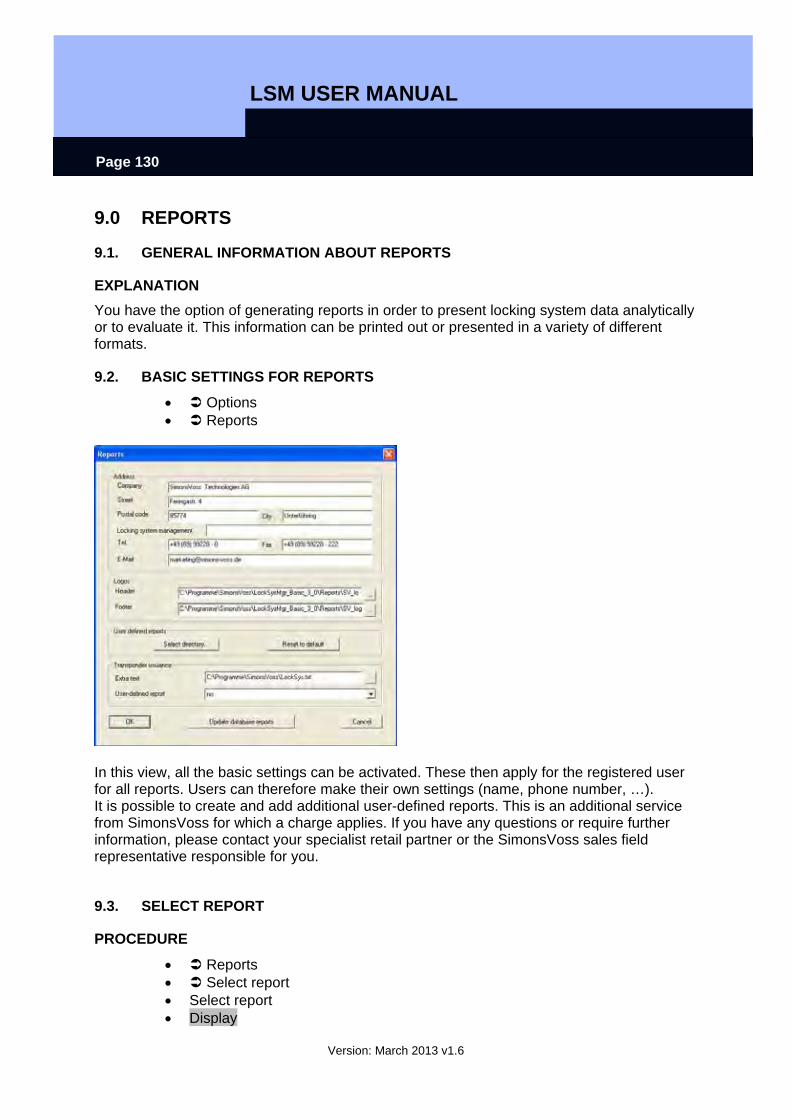
LSM USER MANUAL
Version: March 2013 v1.6
Page 130
9.0 REPORTS
9.1. GENERAL INFORMATION ABOUT REPORTS
EXPLANATION You have the option of generating reports in order to present locking system data analytically or to evaluate it. This information can be printed out or presented in a variety of different formats.
9.2. BASIC SETTINGS FOR REPORTS
• Options • Reports
In this view, all the basic settings can be activated. These then apply for the registered user for all reports. Users can therefore make their own settings (name, phone number, …). It is possible to create and add additional user-defined reports. This is an additional service from SimonsVoss for which a charge applies. If you have any questions or require further information, please contact your specialist retail partner or the SimonsVoss sales field representative responsible for you.
9.3. SELECT REPORT
PROCEDURE
• Reports • Select report • Select report • Display
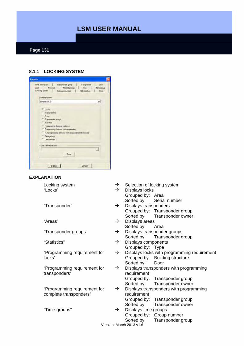
LSM USER MANUAL
Version: March 2013 v1.6
Page 131
8.1.1 LOCKING SYSTEM
EXPLANATION Locking system Selection of locking system “Locks” Displays locks
Grouped by: Area Sorted by: Serial number
“Transponder” Displays transponders Grouped by: Transponder group Sorted by: Transponder owner
“Areas” Displays areas Sorted by: Area
“Transponder groups” Displays transponder groups Sorted by: Transponder group
“Statistics” Displays components Grouped by: Type
“Programming requirement for locks”
Displays locks with programming requirement Grouped by: Building structure Sorted by: Door
“Programming requirement for transponders”
Displays transponders with programming requirement Grouped by: Transponder group Sorted by: Transponder owner
“Programming requirement for complete transponders”
Displays transponders with programming requirement Grouped by: Transponder group Sorted by: Transponder owner
“Time groups” Displays time groups Grouped by: Group number Sorted by: Transponder group

LSM USER MANUAL
Version: March 2013 v1.6
Page 132
“User-defined” Selection of customer-specific reports
8.3.2 AREA
EXPLANATION Locking system Selection of locking system Area Selection of area “Authorised transponder groups” Displays the deviating group rights
Sorted by: Transponder group “Transponders of authorised group”
Displays the transponders of the authorised groups Grouped by: Transponder group Sorted by: Transponder owner
“Exceptions to authorisation” Displays the deviating authorisations Grouped by: Door Sorted by: Transponder owner
“All assigned transponders” Displays assigned transponders Grouped by: Door Sorted by: Transponder owner
“Doors” Displays doors in the selected area Grouped by: Building structure Sorted by: Door
“User-defined” Selection of customer-specific reports

LSM USER MANUAL
Version: March 2013 v1.6
Page 133
8.1.2 TRANSPONDER GROUP
EXPLANATION Locking system Selection of locking system Transponder group Selection of transponder group “Authorisations on doors” Displays the authorisations on doors
Grouped by: Transponder owner Sorted by: Door
“Transponder” Displays transponders Sorted by: Transponder owner
“User-defined” Selection of customer-specific reports

LSM USER MANUAL
Version: March 2013 v1.6
Page 134
8.1.3 DOOR
EXPLANATION Door Selection of door “Detailed overview of authorisations”
Displays authorised transponders Sorted by: Transponder owner
“User-defined” Selection of customer-specific reports
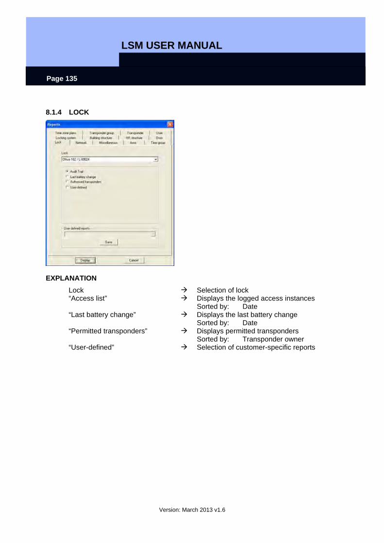
LSM USER MANUAL
Version: March 2013 v1.6
Page 135
8.1.4 LOCK
EXPLANATION Lock Selection of lock “Access list” Displays the logged access instances
Sorted by: Date “Last battery change” Displays the last battery change
Sorted by: Date “Permitted transponders” Displays permitted transponders
Sorted by: Transponder owner “User-defined” Selection of customer-specific reports
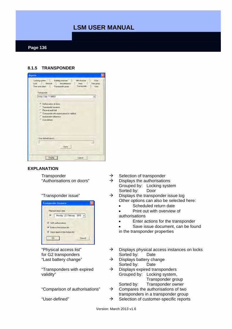
LSM USER MANUAL
Version: March 2013 v1.6
Page 136
8.1.5 TRANSPONDER
EXPLANATION Transponder Selection of transponder “Authorisations on doors” Displays the authorisations
Grouped by: Locking system Sorted by: Door
“Transponder issue”
Displays the transponder issue log Other options can also be selected here: • Scheduled return date • Print out with overview of authorisations • Enter actions for the transponder • Save issue document, can be found in the transponder properties
“Physical access list” for G2 transponders
Displays physical access instances on locks Sorted by: Date
“Last battery change” Displays battery change Sorted by: Date
“Transponders with expired validity”
Displays expired transponders Grouped by: Locking system, Transponder group Sorted by: Transponder owner
“Comparison of authorisations” Compares the authorisations of two transponders in a transponder group
“User-defined” Selection of customer-specific reports
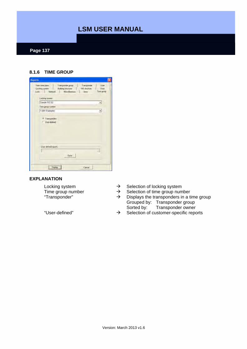
LSM USER MANUAL
Version: March 2013 v1.6
Page 137
8.1.6 TIME GROUP
EXPLANATION Locking system Selection of locking system Time group number Selection of time group number “Transponder” Displays the transponders in a time group
Grouped by: Transponder group Sorted by: Transponder owner
“User-defined” Selection of customer-specific reports
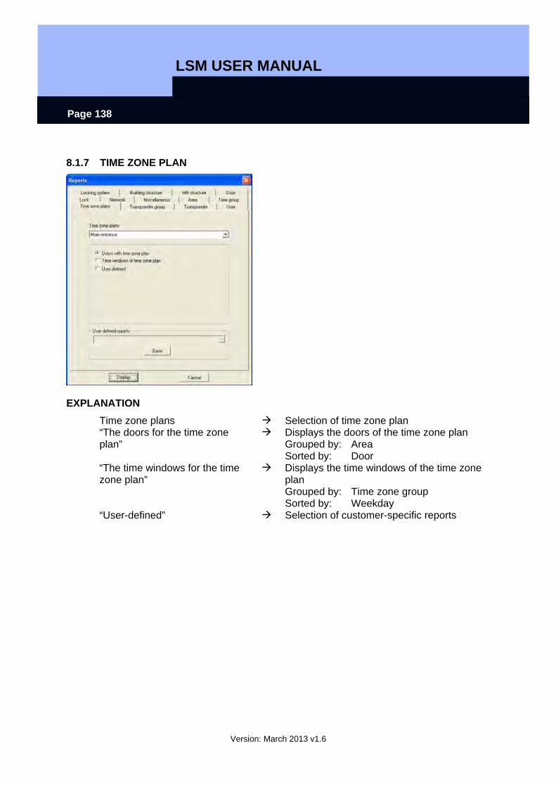
LSM USER MANUAL
Version: March 2013 v1.6
Page 138
8.1.7 TIME ZONE PLAN
EXPLANATION Time zone plans Selection of time zone plan “The doors for the time zone plan”
Displays the doors of the time zone plan Grouped by: Area Sorted by: Door
“The time windows for the time zone plan”
Displays the time windows of the time zone plan Grouped by: Time zone group Sorted by: Weekday
“User-defined” Selection of customer-specific reports
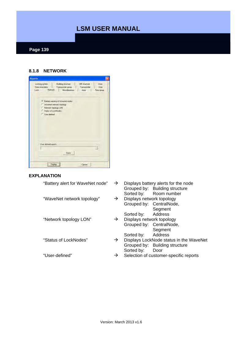
LSM USER MANUAL
Version: March 2013 v1.6
Page 139
8.1.8 NETWORK
EXPLANATION “Battery alert for WaveNet node” Displays battery alerts for the node
Grouped by: Building structure Sorted by: Room number
“WaveNet network topology” Displays network topology Grouped by: CentralNode, Segment Sorted by: Address
“Network topology LON” Displays network topology Grouped by: CentralNode, Segment Sorted by: Address
“Status of LockNodes” Displays LockNode status in the WaveNet Grouped by: Building structure Sorted by: Door
“User-defined” Selection of customer-specific reports
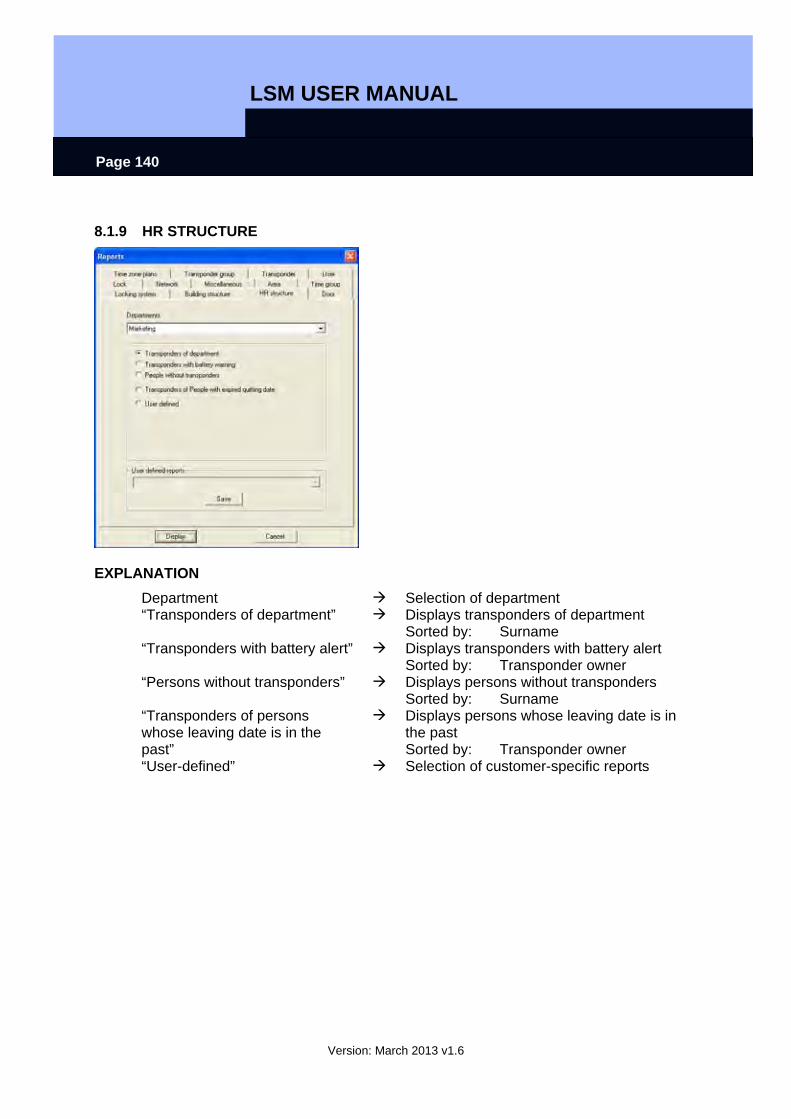
LSM USER MANUAL
Version: March 2013 v1.6
Page 140
8.1.9 HR STRUCTURE
EXPLANATION Department Selection of department “Transponders of department” Displays transponders of department
Sorted by: Surname “Transponders with battery alert” Displays transponders with battery alert
Sorted by: Transponder owner “Persons without transponders” Displays persons without transponders
Sorted by: Surname “Transponders of persons whose leaving date is in the past”
Displays persons whose leaving date is in the past Sorted by: Transponder owner
“User-defined” Selection of customer-specific reports

LSM USER MANUAL
Version: March 2013 v1.6
Page 141
8.1.10 BUILDING STRUCTURE
EXPLANATION Location Selection of location Building Selection of building “Locks” Displays locks
Grouped by: Floor Sorted by: Room number
“Locks with battery alert” Displays locks with battery alert Grouped by: Floor Sorted by: Room number
“Fittings of locking cylinder” Displays fittings of locking cylinder Grouped by: Floor Sorted by: Room number
“Doors without locks” Displays doors without locks Grouped by: Floor Sorted by: Door
“Need for programming on locks”
Displays need for programming on locks Grouped by: Floor Sorted by: Room number
“User-defined” Selection of customer-specific reports
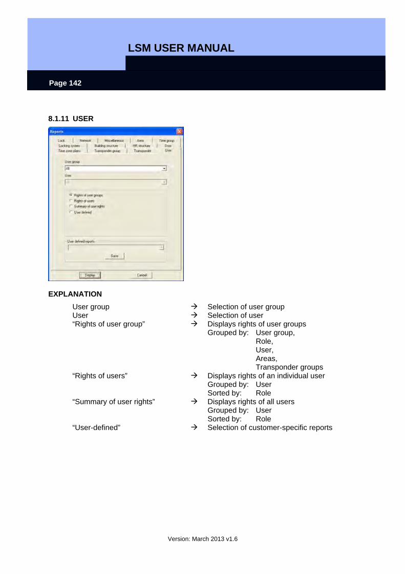
LSM USER MANUAL
Version: March 2013 v1.6
Page 142
8.1.11 USER
EXPLANATION User group Selection of user group User Selection of user “Rights of user group” Displays rights of user groups
Grouped by: User group, Role, User, Areas, Transponder groups
“Rights of users” Displays rights of an individual user Grouped by: User Sorted by: Role
“Summary of user rights” Displays rights of all users Grouped by: User Sorted by: Role
“User-defined” Selection of customer-specific reports
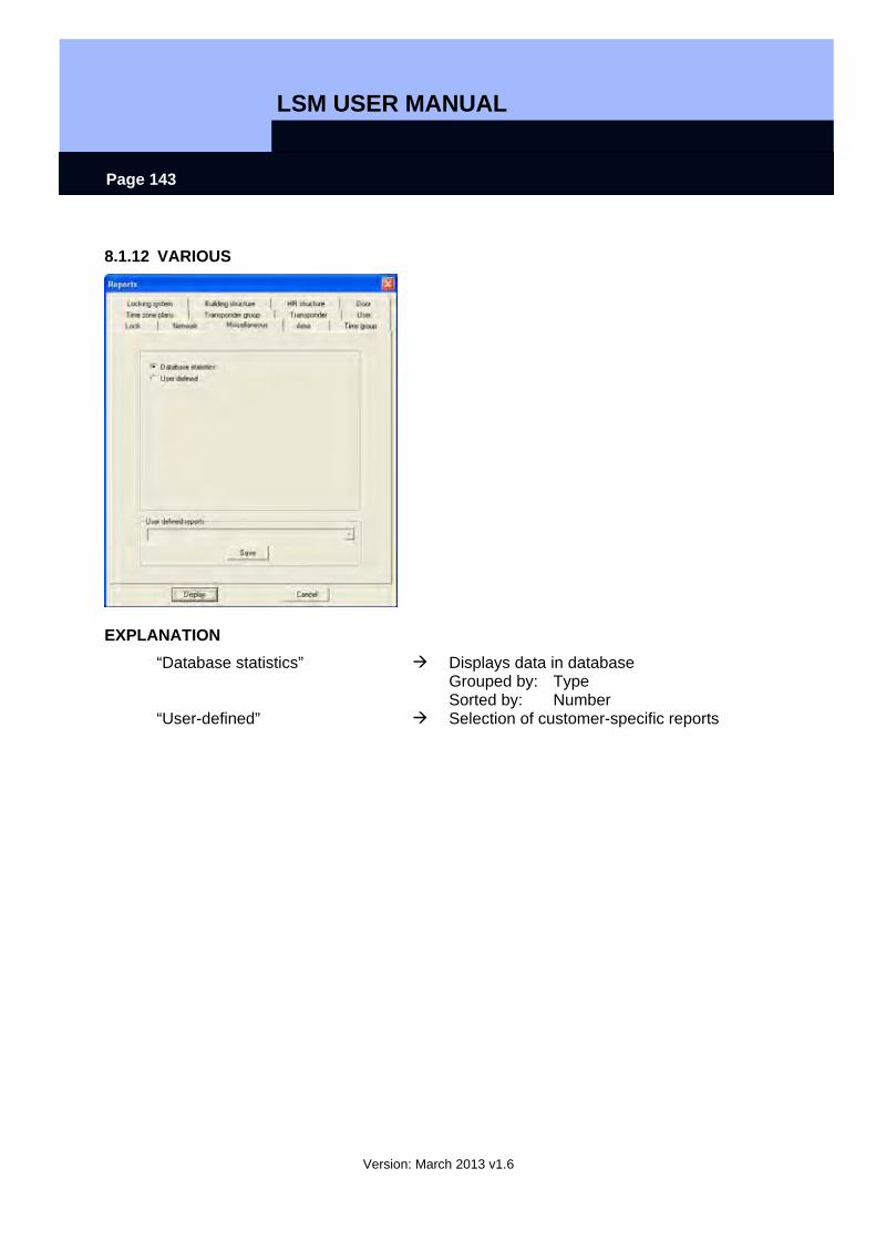
LSM USER MANUAL
Version: March 2013 v1.6
Page 143
8.1.12 VARIOUS
EXPLANATION “Database statistics” Displays data in database
Grouped by: Type Sorted by: Number
“User-defined” Selection of customer-specific reports
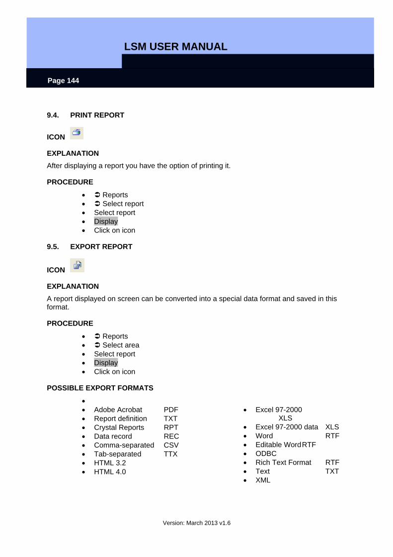
LSM USER MANUAL
Version: March 2013 v1.6
Page 144
9.4. PRINT REPORT
ICON
EXPLANATION After displaying a report you have the option of printing it.
PROCEDURE
• Reports • Select report • Select report • Display • Click on icon
9.5. EXPORT REPORT
ICON
EXPLANATION A report displayed on screen can be converted into a special data format and saved in this format.
PROCEDURE
• Reports • Select area • Select report • Display • Click on icon
POSSIBLE EXPORT FORMATS
• • Adobe Acrobat PDF • Report definition TXT • Crystal Reports RPT • Data record REC • Comma-separated CSV • Tab-separated TTX • HTML 3.2 • HTML 4.0
• Excel 97-2000 XLS
• Excel 97-2000 data XLS • Word RTF • Editable Word RTF • ODBC • Rich Text Format RTF • Text TXT • XML
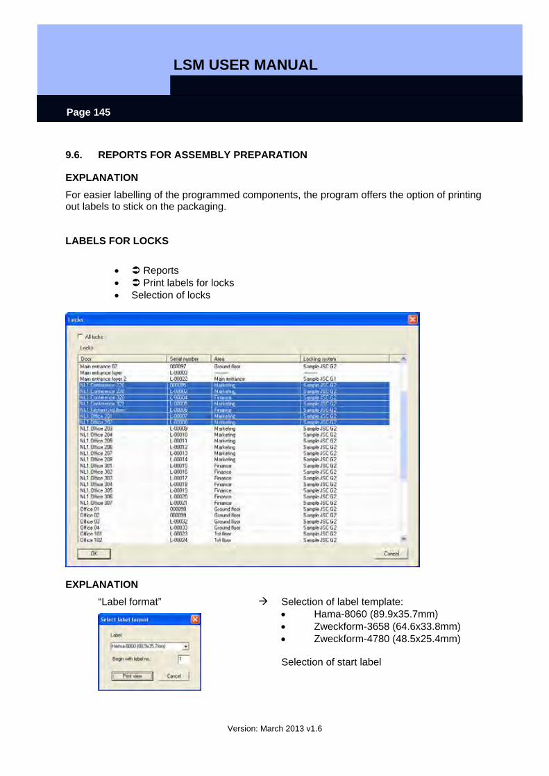
LSM USER MANUAL
Version: March 2013 v1.6
Page 145
9.6. REPORTS FOR ASSEMBLY PREPARATION
EXPLANATION For easier labelling of the programmed components, the program offers the option of printing out labels to stick on the packaging.
LABELS FOR LOCKS
• Reports • Print labels for locks • Selection of locks
EXPLANATION “Label format”
Selection of label template: • Hama-8060 (89.9x35.7mm) • Zweckform-3658 (64.6x33.8mm) • Zweckform-4780 (48.5x25.4mm) Selection of start label
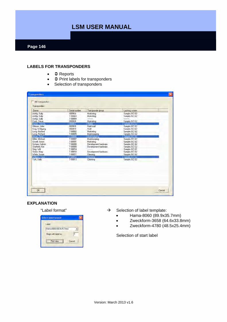
LSM USER MANUAL
Version: March 2013 v1.6
Page 146
LABELS FOR TRANSPONDERS
• Reports • Print labels for transponders • Selection of transponders
EXPLANATION “Label format”
Selection of label template: • Hama-8060 (89.9x35.7mm) • Zweckform-3658 (64.6x33.8mm) • Zweckform-4780 (48.5x25.4mm) Selection of start label
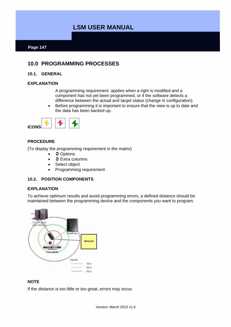
LSM USER MANUAL
Version: March 2013 v1.6
Page 147
10.0 PROGRAMMING PROCESSES
10.1. GENERAL
EXPLANATION A programming requirement applies when a right is modified and a component has not yet been programmed, or if the software detects a difference between the actual and target status (change in configuration).
• Before programming it is important to ensure that the view is up to date and the data has been backed up.
ICONS
PROCEDURE (To display the programming requirement in the matrix)
• Options • Extra columns • Select object • Programming requirement
10.2. POSITION COMPONENTS
EXPLANATION To achieve optimum results and avoid programming errors, a defined distance should be maintained between the programming device and the components you want to program.
NOTE If the distance is too little or too great, errors may occur.
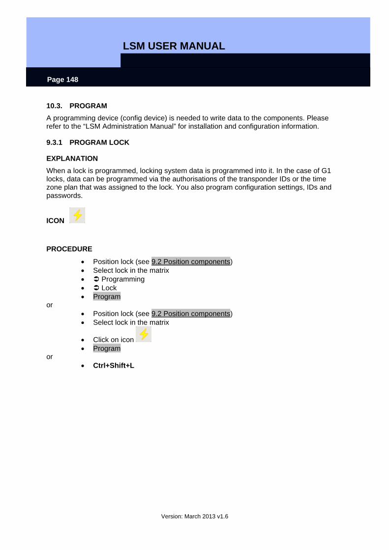
LSM USER MANUAL
Version: March 2013 v1.6
Page 148
10.3. PROGRAM A programming device (config device) is needed to write data to the components. Please refer to the “LSM Administration Manual” for installation and configuration information.
9.3.1 PROGRAM LOCK
EXPLANATION When a lock is programmed, locking system data is programmed into it. In the case of G1 locks, data can be programmed via the authorisations of the transponder IDs or the time zone plan that was assigned to the lock. You also program configuration settings, IDs and passwords.
ICON
PROCEDURE
• Position lock (see 9.2 Position components) • Select lock in the matrix • Programming • Lock • Program
or • Position lock (see 9.2 Position components) • Select lock in the matrix
• Click on icon • Program
or • Ctrl+Shift+L
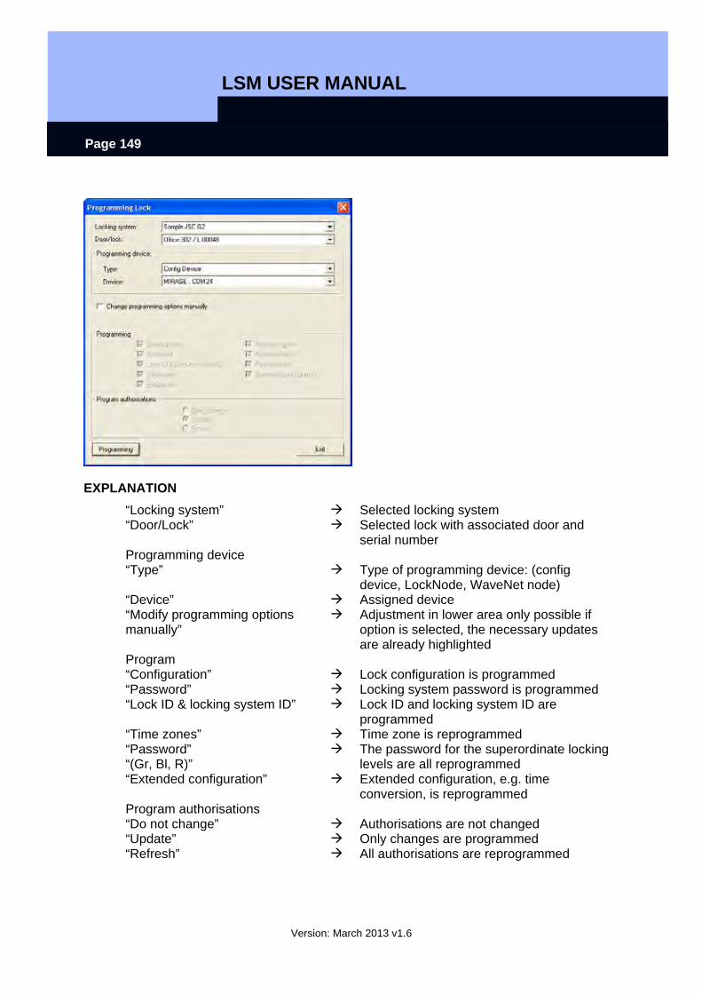
LSM USER MANUAL
Version: March 2013 v1.6
Page 149
EXPLANATION “Locking system” Selected locking system “Door/Lock” Selected lock with associated door and
serial number Programming device “Type” Type of programming device: (config
device, LockNode, WaveNet node) “Device” Assigned device “Modify programming options manually”
Adjustment in lower area only possible if option is selected, the necessary updates are already highlighted
Program “Configuration” Lock configuration is programmed “Password” Locking system password is programmed “Lock ID & locking system ID” Lock ID and locking system ID are
programmed “Time zones” Time zone is reprogrammed “Password” “(Gr, Bl, R)”
The password for the superordinate locking levels are all reprogrammed
“Extended configuration” Extended configuration, e.g. time conversion, is reprogrammed
Program authorisations “Do not change” Authorisations are not changed “Update” Only changes are programmed “Refresh” All authorisations are reprogrammed
LSM USER MANUAL
Version: March 2013 v1.6
Page 150
9.3.2 PROGRAM TRANSPONDER
EXPLANATION When you program a transponder you tell the transponder what its transponder ID is, which locking system it belongs to, what the password for the locking system is and which time group it belongs to. It is also possible to program in a time-based validity.
ICON
PROCEDURE
• Position transponder (see 9.2 Position components) • Select transponder in matrix • Programming • Transponder • Program
or • Position transponder (see Position components) • Select transponder in matrix
• Click on icon • Program
or • Ctrl+Shift+T
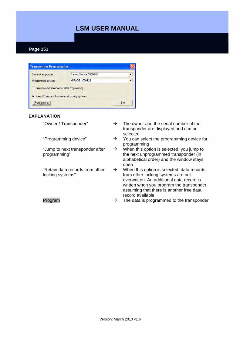
LSM USER MANUAL
Version: March 2013 v1.6
Page 151
EXPLANATION “Owner / Transponder” The owner and the serial number of the
transponder are displayed and can be selected
“Programming device” You can select the programming device for programming
“Jump to next transponder after programming”
When this option is selected, you jump to the next unprogrammed transponder (in alphabetical order) and the window stays open
“Retain data records from other locking systems”
When this option is selected, data records from other locking systems are not overwritten. An additional data record is written when you program the transponder, assuming that there is another free data record available.
Program The data is programmed to the transponder
LSM USER MANUAL
Version: March 2013 v1.6
Page 152
10.4. READ
9.4.1 READ LOCK
EXPLANATION
• A lock with a lock ID which is known to the locking system can be read directly.
• A lock with a lock ID that is not known to the locking system is described as an unknown lock.
ICON
PROCEDURE
• Position lock (see 9.2 Position components)
• Icon or
• Programming • Read lock / set time
or • Read unknown lock
NOTE Different views may appear depending on the read lock.
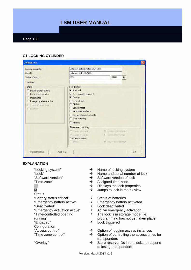
LSM USER MANUAL
Version: March 2013 v1.6
Page 153
G1 LOCKING CYLINDER
EXPLANATION “Locking system” Name of locking system “Lock” Name and serial number of lock “Software version” Software version of lock “Time zone” Assigned time zone … Displays the lock properties M Jumps to lock in matrix view Status “Battery status critical” Status of batteries “Emergency battery active” Emergency battery activated “Deactivated” Lock deactivated “Emergency activation active” Active emergency activation “Time-controlled opening running”
The lock is in storage mode, i.e. programming has not yet taken place
“Engaged” Lock triggered Configuration “Access control” Option of logging access instances “Time zone control” Option of controlling the access times for
transponders “Overlay” Store reserve IDs in the locks to respond
to losing transponders
LSM USER MANUAL
Version: March 2013 v1.6
Page 154
“Long triggering” Longer engagement / switching of lock “OMRON” Use of OMRON mode active “No acoustic programming acknowledgement”
During programming, the lock does not confirm the process by blips
“Log unauthorised access instances”
Logging of unauthorised access instances, only in conjunction with “access control”
“Time changeover” The lock automatically changes the status at set times according to the settings under Time-controlled changeover
“Flip flop” The lock changes the status when an authorised transponder is activated
Transponder list Displays authorised transponders Access list Read access list
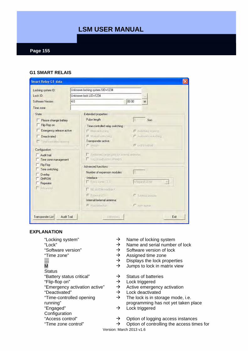
LSM USER MANUAL
Version: March 2013 v1.6
Page 155
G1 SMART RELAIS
EXPLANATION “Locking system” Name of locking system “Lock” Name and serial number of lock “Software version” Software version of lock “Time zone” Assigned time zone … Displays the lock properties M Jumps to lock in matrix view Status “Battery status critical” Status of batteries “Flip-flop on” Lock triggered “Emergency activation active” Active emergency activation “Deactivated” Lock deactivated “Time-controlled opening running”
The lock is in storage mode, i.e. programming has not yet taken place
“Engaged” Lock triggered Configuration “Access control” Option of logging access instances “Time zone control” Option of controlling the access times for
LSM USER MANUAL
Version: March 2013 v1.6
Page 156
transponders “Flip flop” The lock changes the status when an
authorised transponder is activated “Time changeover” The lock automatically changes the
status at set times according to the settings under Time-controlled changeover
“Overlay” Store reserve IDs in the locks to respond to losing transponders
“OMRON” Displays whether use of OMRON mode is active
“Repeater” The lock increases the range and forwards transponder bookings
“Advanced” Advanced version with extended functions
Extended properties “Pulse length” Duration of triggering procedure in
seconds “Limited range (only for internal antennas)”
The range of the internal antenna is reduced
“Log unauthorised access instances”
Logging of unauthorised access instances, only in conjunction with “access control”
Advanced functions “Number of extension modules” Use of extension modules (SOM) “Interface” Lock forwards data to another system “No acoustic programming acknowledgement”
During programming, the lock does not confirm the process by blips
“External LED” Visual outside signal “External blipper” Acoustic outside signal “Internal / external antennas” Displays the antennas used Transponder list Displays authorised transponders Access list Read access list Advanced Read extended configuration

LSM USER MANUAL
Version: March 2013 v1.6
Page 157
G2 LOCK
EXPLANATION “Locking system” Name of locking system “Lock” Name and serial number of lock “Software version” Software version of lock “Time zone” Assigned time zone … Displays the lock properties M Jumps to lock in matrix view Status “Battery status” Status of batteries “Emergency activation” Active emergency activation “Deactivated” Lock deactivated “Engaged” Lock triggered “Storage mode” The lock is in storage mode, i.e.
programming has not yet taken place Data “Device class” Class of read lock “PHI” Public Hardware Identifier (PHI) for
unique identification of G2 components “Time” Current time of lock “Last attempt at access” Result of last access instance Authorisations Displays the authorisations Access list Read authorisations
LSM USER MANUAL
Version: March 2013 v1.6
Page 158
Reset Reset lock
NOTE Whenever you read a known lock, it is simultaneously highlighted in the locking plan.
NOTE The access list function is only available for components with integrated access logging. It is also possible to analyse unauthorised access attempts. This must be defined prior to programming in the lock’s properties. (Lock configuration / data)
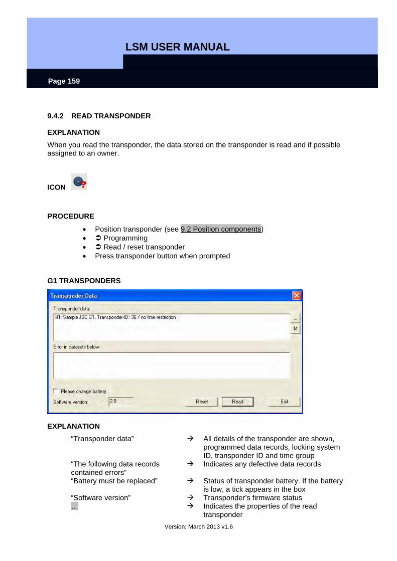
LSM USER MANUAL
Version: March 2013 v1.6
Page 159
9.4.2 READ TRANSPONDER
EXPLANATION When you read the transponder, the data stored on the transponder is read and if possible assigned to an owner.
ICON
PROCEDURE
• Position transponder (see 9.2 Position components) • Programming • Read / reset transponder • Press transponder button when prompted
G1 TRANSPONDERS
EXPLANATION “Transponder data” All details of the transponder are shown,
programmed data records, locking system ID, transponder ID and time group
“The following data records contained errors”
Indicates any defective data records
“Battery must be replaced” Status of transponder battery. If the battery is low, a tick appears in the box
“Software version” Transponder’s firmware status … Indicates the properties of the read
transponder
LSM USER MANUAL
Version: March 2013 v1.6
Page 160
M Indicates the read transponder in the matrix
NOTE Whenever you read the transponder it is simultaneously highlighted in the locking plan. Transponders with a validity period have additional information:
• Activation date if defined, date as of which transponder is valid • Expiry date if defined, date until which transponder is valid
ATTENTION Transponders with a validity period can only be authorised in one single locking system.
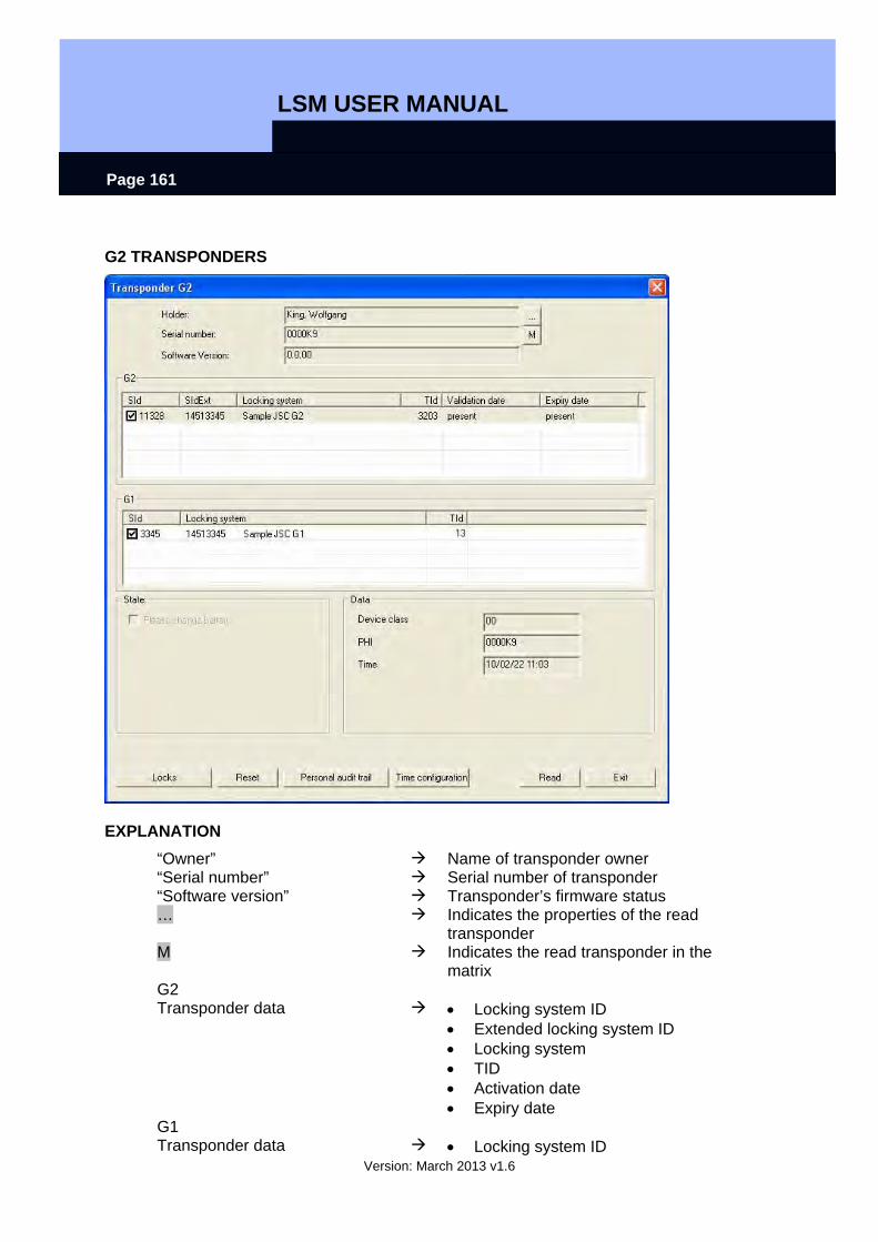
LSM USER MANUAL
Version: March 2013 v1.6
Page 161
G2 TRANSPONDERS
EXPLANATION “Owner” Name of transponder owner “Serial number” Serial number of transponder “Software version” Transponder’s firmware status … Indicates the properties of the read
transponder M Indicates the read transponder in the
matrix G2 Transponder data • Locking system ID
• Extended locking system ID • Locking system • TID • Activation date • Expiry date
G1 Transponder data • Locking system ID
LSM USER MANUAL
Version: March 2013 v1.6
Page 162
• Locking system • TID
Status “Battery status critical” This component requires the battery to
be changed “Battery status critical” “Device class” Class of read lock “PHI” Public Hardware Identifier (PHI) for
unique identification of G2 components “Time” Current time of transponder Authorisations Displays the authorisations Reset The highlighted transponder data record
is reset Physical access list Read physical access list
Read Read (another) transponder
NOTE Whenever you read the transponder it is simultaneously highlighted in the locking plan.
LSM USER MANUAL
Version: March 2013 v1.6
Page 163
10.5. RESET
10.5.1 RESET LOCK
EXPLANATION When a lock is reset the data on the lock is removed and the lock's actual status is deleted in the software.
PROCEDURE
• Position lock (see 9.2 Position components) • Select lock in matrix • Programming • Reset lock
or • Position lock (see 9.2 Position components) • Select lock in matrix • Ctrl+Shift+N
10.5.2 RESET TRANSPONDER
EXPLANATION When a transponder is reset the data on the transponder is removed and the transponder’s actual status is deleted in the software.
PROCEDURE
• Position transponder (see 9.2 Position components) • Select transponder in matrix • Programming • Reset transponder
or • Position transponder (see 9.2 Position components) • Select transponder in matrix • Ctrl+Shift+R
NOTE If a component is deleted in the software before being reset, you will need the password for the locking system in order to reset the component later.
LSM USER MANUAL
Version: March 2013 v1.6
Page 164
10.6. MOBILE PROGRAMMING
10.6.1 GENERAL
EXPLANATION In LSM, you have the option of configuring the export of locking plan data to a mobile end device (a PocketPC by default) such that certain employees can perform particular tasks on particular locks. These employees must also log on to the software on the PocketPC, allowing only authorised employees access to data.
NOTE The software access data should be kept safe according to the valid IT guidelines and not made accessible to unauthorised persons.
SCENARIO 1 (STANDARD)
EXPLANATION The data is immediately transferred to the PocketPC and can be run immediately.
PROCEDURE
• File • Export to PDA • LSM Mobile • Select PDA user • Select locking systems • Select locks • Configure tasks • Select transponders • Export
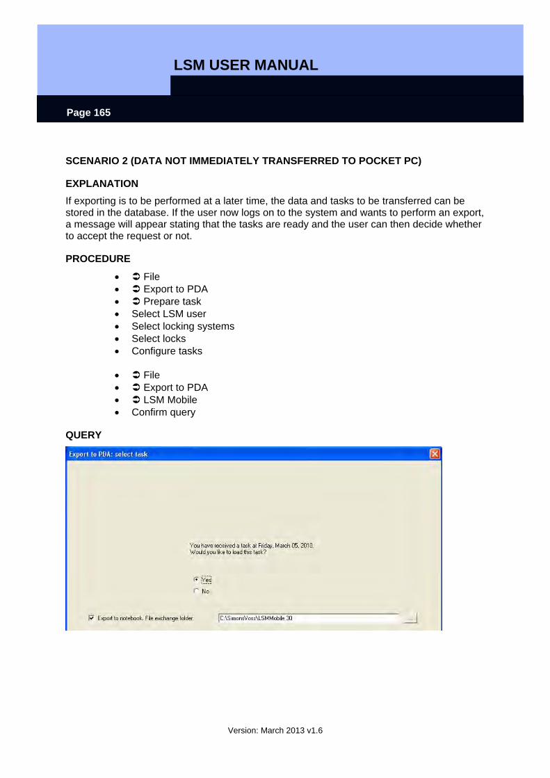
LSM USER MANUAL
Version: March 2013 v1.6
Page 165
SCENARIO 2 (DATA NOT IMMEDIATELY TRANSFERRED TO POCKET PC)
EXPLANATION If exporting is to be performed at a later time, the data and tasks to be transferred can be stored in the database. If the user now logs on to the system and wants to perform an export, a message will appear stating that the tasks are ready and the user can then decide whether to accept the request or not.
PROCEDURE
• File • Export to PDA • Prepare task • Select LSM user • Select locking systems • Select locks • Configure tasks
• File • Export to PDA • LSM Mobile • Confirm query
QUERY
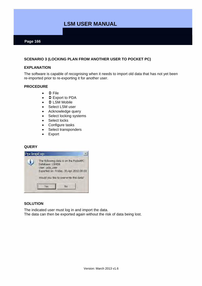
LSM USER MANUAL
Version: March 2013 v1.6
Page 166
SCENARIO 3 (LOCKING PLAN FROM ANOTHER USER TO POCKET PC)
EXPLANATION The software is capable of recognising when it needs to import old data that has not yet been re-imported prior to re-exporting it for another user.
PROCEDURE
• File • Export to PDA • LSM Mobile • Select LSM user • Acknowledge query • Select locking systems • Select locks • Configure tasks • Select transponders • Export
QUERY
SOLUTION The indicated user must log in and import the data. The data can then be exported again without the risk of data being lost.
LSM USER MANUAL
Version: March 2013 v1.6
Page 167
SCENARIO 4 (PART OF LOCKING PLAN ALREADY EXPORTED)
EXPLANATION You can work with multiple Pocket PCs at the same time. To avoid duplicating any work, locks that have already been exported should not be exported again.
PROCEDURE
• File • Export to PDA • LSM Mobile • Select LSM user • Select locking systems • Select locks • Tick “Previously exported locks ...” • Configure tasks • Select transponders • Export
10.6.2 EXPORT
EXPLANATION When data is exported, the locking plan is transferred to the Pocket PC in accordance with the defined restrictions in order to be able to program the locks in situ.
NOTE
• Only users who have been assigned the “handheld” role are listed. • With LSM you have the option of managing more than one locking plan at the
same time on your PocketPC.
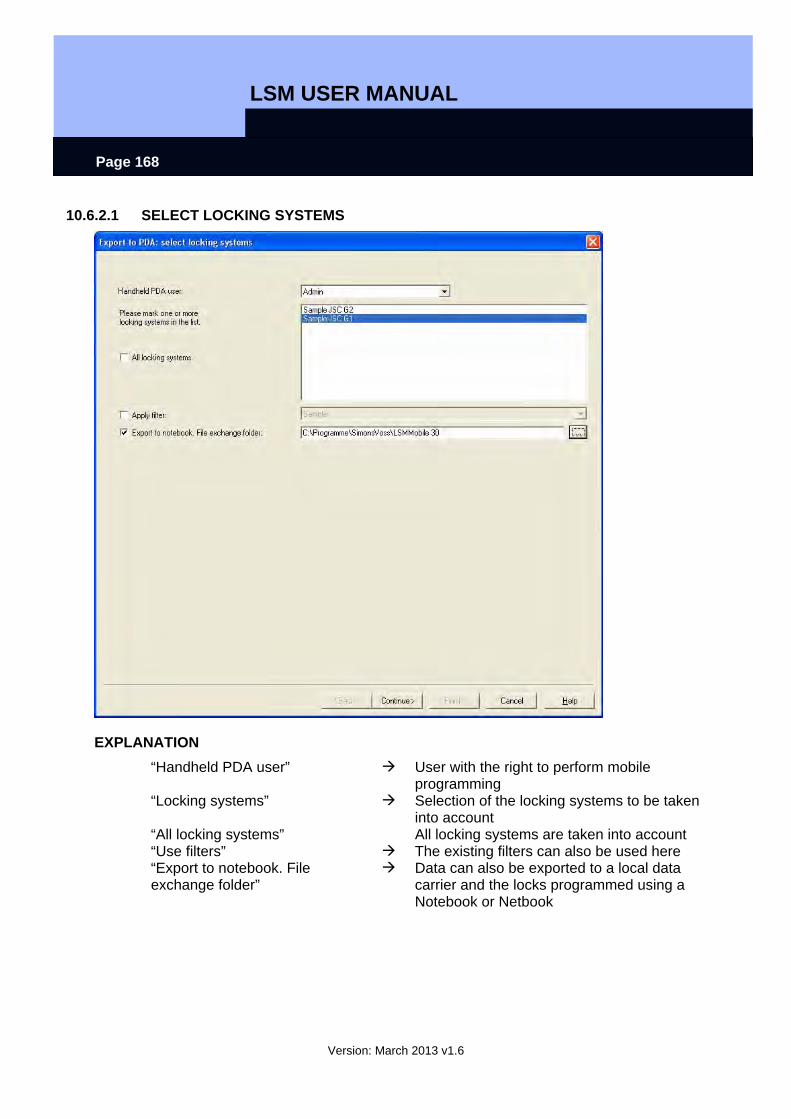
LSM USER MANUAL
Version: March 2013 v1.6
Page 168
10.6.2.1 SELECT LOCKING SYSTEMS
EXPLANATION “Handheld PDA user” User with the right to perform mobile
programming “Locking systems” Selection of the locking systems to be taken
into account “All locking systems” All locking systems are taken into account “Use filters” The existing filters can also be used here “Export to notebook. File exchange folder”
Data can also be exported to a local data carrier and the locks programmed using a Notebook or Netbook
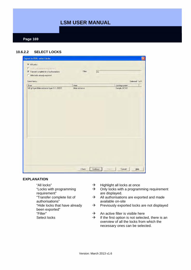
LSM USER MANUAL
Version: March 2013 v1.6
Page 169
10.6.2.2 SELECT LOCKS
EXPLANATION “All locks” Highlight all locks at once “Locks with programming requirement”
Only locks with a programming requirement are displayed.
“Transfer complete list of authorisations”
All authorisations are exported and made available on-site
“Hide locks that have already been exported”
Previously exported locks are not displayed
“Filter” An active filter is visible here Select locks If the first option is not selected, there is an
overview of all the locks from which the necessary ones can be selected.
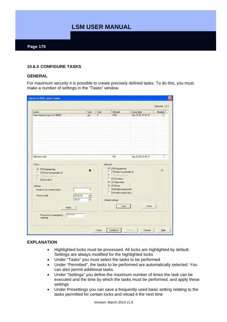
LSM USER MANUAL
Version: March 2013 v1.6
Page 170
10.6.3 CONFIGURE TASKS
GENERAL For maximum security it is possible to create precisely defined tasks. To do this, you must make a number of settings in the “Tasks” window.
EXPLANATION
• Highlighted locks must be processed. All locks are highlighted by default. Settings are always modified for the highlighted locks
• Under “Tasks” you must select the tasks to be performed • Under “Permitted”, the tasks to be performed are automatically selected. You
can also permit additional tasks. • Under “Settings” you define the maximum number of times the task can be
executed and the time by which the tasks must be performed, and apply these settings
• Under Presettings you can save a frequently used basic setting relating to the tasks permitted for certain locks and reload it the next time
LSM USER MANUAL
Version: March 2013 v1.6
Page 171
• For an emergency opening with LSM Mobile, you do not need to know the original locking system password. Under “Password for emergency opening” you can issue an 8-digit password of your own choice with which the user can open the lock in an emergency.
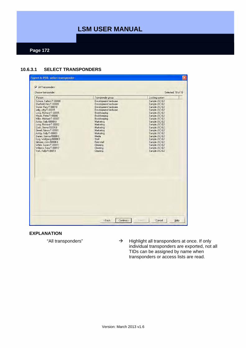
LSM USER MANUAL
Version: March 2013 v1.6
Page 172
10.6.3.1 SELECT TRANSPONDERS
EXPLANATION “All transponders” Highlight all transponders at once. If only
individual transponders are exported, not all TIDs can be assigned by name when transponders or access lists are read.
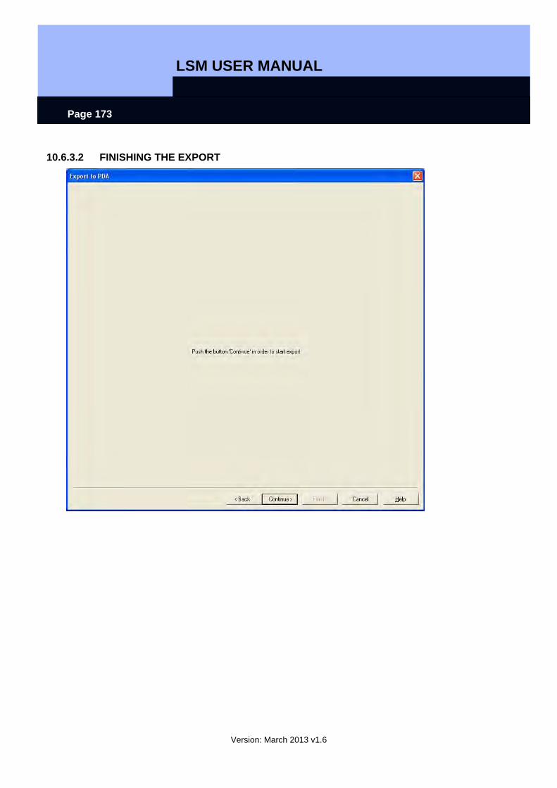
LSM USER MANUAL
Version: March 2013 v1.6
Page 173
10.6.3.2 FINISHING THE EXPORT
LSM USER MANUAL
Version: March 2013 v1.6
Page 174
10.6.4 IMPORT
EXPLANATION Once the exported tasks have been completed, the data must be re-imported from the Pocket PC after processing in order to inform the locking plan of the modified data. If this does not happen you will see a query the next time you try to export and different authorisations may apply in the software and in the locks!!
PROCEDURE
• File • Import to PDA • LSM Mobile
NOTE
• In the export task list you can select whether all tasks should be imported or just those that have already been processed
• If the software detects differences between the handheld and the computer, it will show you these. You can then decide which data you want to accept.
LSM USER MANUAL
Version: March 2013 v1.6
Page 175
10.7. LSM MOBILE
EXPLANATION LSM Mobile is the SimonsVoss software module for PocketPCs. You can use this software and the mobile Pocket PC to perform tasks within a locking system without network (offline).
DATA SYNCHRONISATION REQUIREMENT
• Microsoft ActiveSync Version 4.2 (or higher) • LSM Mobile installed on PocketPC • LSM Mobile must not be open
SCENARIO 1 (EXECUTE)
PROCEDURE
• Start LSM Mobile • Confirm Bluetooth query with Yes • Select database • Enter login details (user name and password) • Confirm with OK • Select locking system • Execute

LSM USER MANUAL
Version: March 2013 v1.6
Page 176
PROCESS
• LSM Mobile reads unknown locks • LSM Mobile recognises lock and performs the “tasks” stored for the lock
SCENARIO 2 (SELECT – PROGRAM)
PROCEDURE
• Start LSM Mobile • Confirm Bluetooth query with Yes • Select database • Enter login details (user name and password) • Select locking system • Select • Select lock • Program.
PROCESS
• LSM Mobile programs the nearby lock (you can also program locks that have not been programmed yet)
NOTE
• After exporting the locking plan to the Pocket PC, you should avoid making any changes to the LSM locking plan software until you import it again to prevent conflicts from arising.
• More detailed information about LSM Mobile is available in a separate manual from SimonsVoss.
LSM USER MANUAL
Version: March 2013 v1.6
Page 177
11.0 MISCELLANEOUS
11.1. DELETING AN EMPLOYEE WHEN TRANSPONDER IS RETURNED Reset transponder Disconnect transponder from person
11.2. DELETING AN EMPLOYEE WHEN TRANSPONDER IS NOT RETURNED Deactivate / block transponder
11.3. CREATE REPLACEMENT TRANSPONDER
USE This procedure should be used when a transponder has been lost.
EXPLANATION When you create a replacement transponder, the original transponder is blocked and a new one is created with the same authorisations and a similar designation.
PROCEDURE
• Right-click on the original transponder • New • Replacement transponder • Confirm query with Yes • Enter additional information and confirm • Enter new serial number
RESULTS
• Programming requirement on transponder • Programming requirement on the affected locks • TID is permanently blocked
LSM USER MANUAL
Version: March 2013 v1.6
Page 178
11.4. PROCEDURE TO FOLLOW FOR A DEFECTIVE TRANSPONDER
EXPLANATION In the event of a defective transponder, before programming a new transponder you must tell the software that the old transponder no longer works.
PROCEDURE
• Right-click on the original transponder • Properties • Transponder
or • Edit • Transponder • Select transponder using arrow buttons
then • Software reset • Select reason • Enter additional information if required • Confirm twice with Yes • You can now start programming the new transponder
RESULTS
• Actual status of the original transponder is reset
NOTE Resetting and reprogramming another transponder can lead to security issues. It is possible to create two transponders with the same data. It must be ensured that the original transponder really is defective. Otherwise a replacement transponder must be created (see 10.1 Deleting an employee when transponder is returned).
LSM USER MANUAL
Version: March 2013 v1.6
Page 179
11.5. PROCEDURE TO FOLLOW FOR REPLACING A DEFECTIVE LOCK
EXPLANATION When you replace a defective lock, before programming a new lock you must tell the LSM database that the old lock no longer works.
PROCEDURE
• Right-click on the door / lock • Properties • Lock
or • Edit • Lock • Select lock using arrow buttons
then • Configuration / data • Software reset • Confirm query with Yes • You can now start programming the new lock
RESULTS Actual status of the lock is reset
LSM USER MANUAL
Version: March 2013 v1.6
Page 180
11.6. OVERLAY MODE
EXPLANATION In overlay mode 8 transponder IDs are reserved for a created transponder and programmed into the authorised locks. If the first transponder is lost, the transponder ID is deactivated in the software and the new transponder is assigned the next transponder ID from the reserve TIDs. When the transponder is used to open a lock, the system recognises that this is one of the 7 reserve TIDs and deactivates the previous transponder ID.
ADVANTAGE
• Lock devices do not need to be programmed immediately when a transponder is lost. The locking devices concerned must be re-programmed to eliminate the programming requirement.
DISADVANTAGE
• The old TID is only deactivated on the locks the user has activated with his new TID, resulting in a security problem
• Large number of used transponder IDs �(e.g. 1000 transponders 8000 TIDs)
11.7. OVERALL LOCKING LEVELS
EXPLANATION In order to create transponders which are to be authorised for more than three locking systems, you need to use higher-ranking locking levels. The transponders are from different user group locking systems. The transponder group hierarchy can be used in cases where there are a number of locking systems in an installation. A typical example of overlapping locking levels is the fire service level (red) as there are situations in which the transponders for this level are authorised over several locking systems in different buildings and for different companies. When such a level is created, an overlapping level must be set up in each locking system concerned and the transponders authorised for the individual locking devices.
11.7.1. CREATING A HIGHER-LEVEL LOCKING LEVEL Overlapping locking levels are created and managed in the same way as a locking system. When adding new locking devices to a standard level (black), the colour level must also be added where necessary. If this is not the case, the overlapping transponder is not able to activate this locking device. Other levels may now be added (max. three per locking device) using the same
LSM USER MANUAL
Version: March 2013 v1.6
Page 181
procedure. The crosses are colour-coded according to their level: green, blue or red. Note
• A locking device is not able to differentiate between two levels of the same colour. You must therefore decide on one.
• You can also programme a higher ranking transponder in two other locking systems as a normal transponder.
• As a basic rule, a transponder can only ever contain one higher ranking locking level.
11.7.2 CREATING A HIGHER RANKING TRANSPONDER G1 locking systems A locking device is able to distinguish between up to three higher ranking locking levels (represented by green, blue and red). Within a higher ranking locking level, all transponders have equal rights since transponders all receive the same TID. 1. Green TID from 7593 to 7792 2. Blue TID from 7793 to 7992 3. Red TID from 7993 to 8192 4. Black TIDs from 8 to 7592 G2 locking systems G2 locking systems distinguish between individual transponders in overlapping levels based on their TID You must therefore ensure that users in the different systems always receive the same transponder IDs, so that they may always be authorised correctly. 1. Green TIDs from 128 to 1151 2. Blue TIDs from 1152 to 2175 3. Red TIDs from 2176 to 3199 4. Black TIDs from 3200 to 65407

LSM USER MANUAL
Version: March 2013 v1.6
Page 182
4.0 SERVICE AND SUPPORT
PRODUCT SUPPORT If customers have any questions relating to products from SimonsVoss Technologies AG, the general support team will be happy to help: Telephone +49 (0) 1805 78 3060 The product hotline does not offer support for the LSM Business and Professional software. Software support Support Standard For customers with a chargeable Support Standard software agreement, the following support options are also available:
E-MAIL [email protected]
TELEPHONE +49 (0) 1805 57 3060 Support Premium For customers with a chargeable Support Premium software agreement, the following support options are also available: E-mail [email protected] Telephone +49 (0) 1805 57 3060 Online support tool Short call to LSM hotline Launch LSM
areas,
SIMONSVOSS ONLINE SUPPORT