manual for on-site sewage management systems...on-site sewage management systems manual page 140 of...
TRANSCRIPT
On-Site Sewage Management Systems Manual Page 136 of 287
Manual for On-Site Sewage Management Systems
SECTION F │ DISPERSAL SYSTEMS
Environmental Health Section
Georgia Department of Public Health

SECTION F │ Dispersal Systems
On-Site Sewage Management Systems Manual Page 137 of 287
SECTION F – DISPERSAL SYSTEMS
1) Preface
Subsurface dispersal systems are portions of on-site sewage management systems that accept effluent from sewage pretreatment units for further treatment by microbial life within the soil. Treatment also occurs by filtration, chemical decomposition and chemical bonding within the soil itself. These systems consist of: A. Devices and piping to transport effluent under pressure or by gravity flow and distribute
the effluent to the soil absorption surfaces; B. Trenches, chambers, mounds, drip emitter lines and others, separately or in combination,
which form or enclose the soil absorption surfaces; and C. Rock, gravel, peat or other fill materials required within the system including barrier
materials and fill soil within or over the system.
2) Aggregate Absorption Field Systems
A. Conventional Septic Tank System – This means a septic tank and absorption field system composed of perforated pipe surrounded by gravel or stone masking for the infiltration of effluent into the adjoining bottom and side soil areas. The Department’s Technical Review Committee may recommend approval of other types of aggregate for use in conventional septic tank systems.
B. Location – Absorption fields shall be installed in areas protected from excessive surface water, ponding or runoff, including but not limited to storm water and discharge from building gutters. Absorption fields shall not be installed where slopes exceed 25% unless the results of special investigations demonstrate that the slope limitation can be overcome by design or site modification. Any site modification plan must be approved by the local County Board of Health prior to modifications being carried out. There shall be a minimum of 24 inches of vertical separation from the absorption field trench bottom to any seasonal groundwater table, rock or impervious soil layer. Greater vertical separation distances may be required if special investigations indicate a potential for groundwater contamination. On lots or parcels of land less than 3 acres, the maximum percolation rate shall not exceed 90 minutes per inch. If properties are served by individual water supply systems, the absorption field shall be installed not less than 50 feet from property lines unless wells and on-site sewage management systems are already in place on surrounding property and the required 100 feet separation distance between wells and absorption fields can be maintained. In pre-planned developments, where sites for individual water supplies and on-site sewage management systems are pre-located so as to maintain the 100 feet separation distance, absorption fields may be installed less than 50 feet, but not less than five feet from property lines. No part of the absorption field other than solid schedule 40 PVC or equivalent pipe with watertight joints shall be covered by buildings, pavements, or used for parking automotive vehicles or vehicular traffic. There shall be available sufficient unobstructed land area, meeting all requirements for the installation of an on-site sewage management system, to provide for the complete replacement of the absorption field. If

SECTION F │ Dispersal Systems
On-Site Sewage Management Systems Manual Page 138 of 287
topographical features permit, this requirement can be met by installing the initial absorption trenches on 16 feet centers, thus allowing for replacement between the original trenches. Septic tanks and absorption fields are prohibited within 150 feet of any perennial stream bank in a large water supply watershed tributary that is upstream to a water supply reservoir of a governmentally owned public drinking water supply intake and within a seven mile radius of the reservoir boundary as required by Rules of the Georgia Department of Natural Resources, Environmental Protection Division, Chapter 391-3-16-.01-Criteria for Water Supply Watersheds (hereafter Chapter 391-3-16-.01). In a small water supply watershed: septic tanks and absorption fields are prohibited within 150 feet of any perennial stream bank upstream of a small water supply reservoir of a governmentally owned public drinking water supply intake within a seven mile radius of the intake or water supply reservoir; additionally these are further prohibited within 75 feet of any perennial stream bank upstream and outside the seven mile radius within the small water supply watershed as required by Chapter 391-3-16-.01. Absorption fields may not be installed in the 100 feet buffer area of rivers classified for protection under the Rules of the Department of Natural Resources, Environmental Protection Division, Chapter 391-3-16-.04 Criteria for River Corridor Protection.
C. Minimum Design and Construction Criteria: 1. Absorption lines and absorption trench bottoms shall be true to grade. 2. Trench bottom depth shall be based on soil conditions as determined by criteria in this
Manual. 3. A minimum of six to twelve inches of earth cover is required over absorption lines. 4. Absorption line laterals shall be spaced a minimum of seven feet apart, center to
center. 5. Absorption trenches shall be no more than 36 inches wide. 6. The minimum depth of aggregate shall be twelve inches with six inches below the
perforated pipe and filled to two inches above the pipe. 7. Perforated pipe shall be laid in the center of the trench with the perforations oriented
toward the bottom of the trench. 8. A layer of pervious building paper, straw or similar permeable material approved by
the Technical Review Committee shall be placed over the aggregate before back filling.
9. Approved solid pipe and fittings with sealed, watertight joints shall be used for horizontal and vertical changes in direction or grade and to cross under roadways or paved areas. Sections of solid pipe shall not be considered in determining the total absorption trench bottom area.
10. Excavation for absorption trenches in soils other than sands shall not be conducted when wet due to the potential irreversible damage to soil structure, such as compaction and smearing.
D. Perforated Pipe – Gravity Flow Usage:

SECTION F │ Dispersal Systems
On-Site Sewage Management Systems Manual Page 139 of 287
1. All perforated pipe used for gravity flow carriage and distribution of effluent within lateral trenches, mounds or other such applications shall meet 1,500 1b crush strength in accordance with ASTM - F810 standards for rigid piping and ASTM – F667 for corrugated semi-rigid piping.
2. Each standard section of pipe as supplied by the manufacturer shall be plainly marked, embossed or engraved showing the manufacturer’s name, the type of pipe material and showing the product meets applicable ASTM standards and a bearing load of 1,500 lbs. per foot. In addition, a painted or other clear line shall be marked on each section of pipe to denote the top.
3. For conventional systems, all gravity flow usage perforated pipe shall have a minimum internal diameter of four inches.
4. All four-inch diameter or greater pipe shall have at least two rows of holes between ½ inch and ¾ inch in diameter, evenly spaced and placed within an arc of 120 degrees on the bottom of the pipe with a third hole of same size being directly opposite the top marking. Spacing of holes longitudinally shall be every 4 inches on centers along the length of the pipe.
E. Absorption Field Sizing: 1. The absorption field area shall be based upon the anticipated peak daily volume of
treated sewage, waste stream characteristics and the characteristics of the soil in the absorption field location.
2. Prior to application to the soil, the waste stream must have a BOD5 and TSS of 200 mg/l or less. In addition, grease generating facilities shall reduce the fats, oil and grease content of their waste stream to 25mg/l prior to application to the soil.
3. Soil absorption rates shall determine the absorption trench bottom area of the absorption field.
4. Sewage flow rates for individual residences shall be based on the number of bedrooms. Table 10.F relates bedrooms to absorption rates for determining the absorption field trench bottom area required.
5. Sewage flow rates for other facilities shall be based on criteria in Section J of this Manual. Absorption field trench bottom area for other facilities shall be based on the below formula.
Formula for Sewage Flow Rates for Non-Residential Facilities percolation coefficient (√𝑡𝑡 5⁄ ) x gallons per day = Linear feet
trench bottom width (feet)
3) Absorption Field Methods for Conventional Septic Tank Systems
A. Distribution Box Method – On level or sloping topography, the distribution box method may be used and shall be required when dosing tanks are used. A firm earthen foundation secured by concrete or concrete foundation for distribution boxes extending at least 12 inches beyond the walls of the box shall be provided to insure against tilting of the distribution box. Installation of the distribution box shall be made to provide equal flow to each absorption line extending from the box. The top of the distribution box shall have a

SECTION F │ Dispersal Systems
On-Site Sewage Management Systems Manual Page 140 of 287
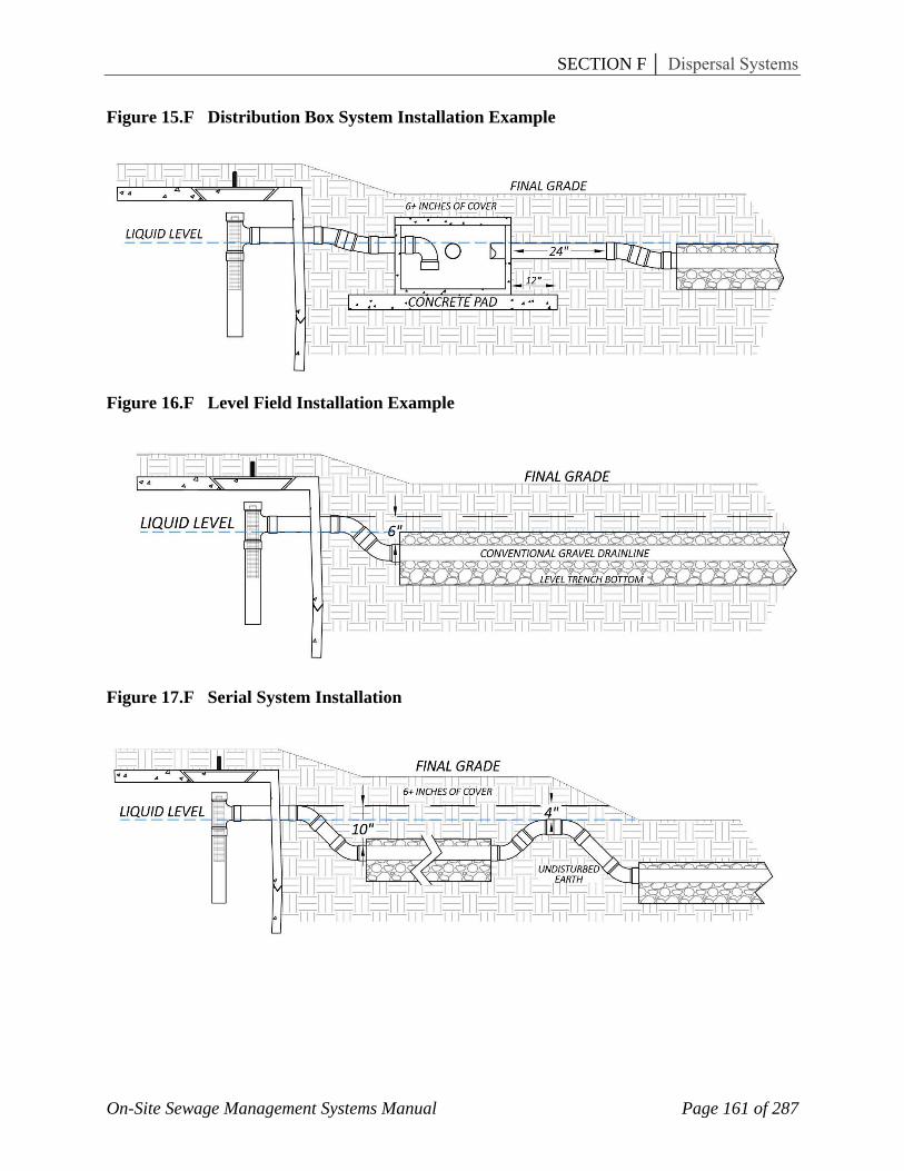
minimum earth cover of six inches, but no more than twelve inches unless provisions are made for easy access to the distribution box. The sewer from the septic tank or dosing tank shall enter the distribution box and terminate inside the distribution box with an elbow turned downward to form a submerged outlet at normal water level to minimize turbulence. Alternately, a baffle may be used if the same function is accomplished. Absorption lines of equal length shall be connected to the distribution box outlets by watertight independent sewers consisting of four-inch schedule 40 PVC pipe or equivalent. All independent sewer lines shall be installed level at the same elevation for two feet. Beginning two feet from the distribution box to the beginning of the absorption line, independent sewer lines shall be installed to provide a minimum downward grade change of two inches from the distribution box outlet to the perforated pipe at the beginning of the absorption line. Absorption lines shall be installed level or on a uniform grade of no more than four inches of fall for the entire length of the individual absorption line. Absorption lines from distribution boxes used in conjunction with dosing tanks shall not exceed 125 feet in length (See Figure 15.F).
B. Level Field Method – On level or sloping topography of five percent or less, the level field method may be used. When this method is used, the absorption field shall be installed level, with all absorption lines interconnected to form a continuous system. A standard tee fitting or approved distribution device shall be used to interconnect the absorption lines. When this method is used, the invert of the absorption line shall be at least six inches lower than the invert of the septic tank outlet. An absorption field consisting of a single absorption line up to 125 feet in length may be installed level without interconnection (See Figure 16.F).
C. Serial Distribution Method – On sloping topography, the serial distribution method may be used. When this method is used, level absorption trenches shall be constructed parallel along the ground contours. The sewer from the septic tank shall enter the uppermost absorption line and terminate at any point in the line so all effluent from the septic tank is discharged into the first absorption line. Adjacent absorption lines shall be successively connected by means of overflow sewers constructed at any point along the absorption line in such a manner that each absorption trench fills with effluent to the full depth of the aggregate before the effluent flows through the overflow sewer to the next trench. The invert of the first overflow sewer must be at least four inches lower than the invert of the septic tank outlet. At the point an overflow sewer leaves an absorption trench, the excavation for the overflow sewer shall be dug no deeper than the top of the aggregate in the absorption trench, so that a minimum 12-inch undisturbed block of earth will remain in place for the full depth of the aggregate. Overflow sewers shall be laid on undisturbed earth with a minimum earth cover of six inches. All pipe and sewer fittings shall be NSF International schedule 40 PVC or equivalent (See Figure 17.F).
D. Alternating Field Method – When the soil percolation rate is over 60 minutes per inch, but less than 90 minutes per inch or soil evaluation reports indicate the absorption rate to be between 60 and 90 minutes per inch, an alternating absorption field system may be considered. If used, the total absorption field area required by the percolation rate shall be divided into two equal but separate systems (See Figure 18.F). A diversion device shall be used to divert sewage flow from one field to the other (See Figure 18.F). Each field should be utilized for one year before diverting flow to the alternate field so as to give each field a satisfactory resting period, unless the field receiving the flow becomes saturated before

SECTION F │ Dispersal Systems
On-Site Sewage Management Systems Manual Page 141 of 287
one year’s use. In the case of saturation of one field, the flow should be immediately diverted to the other field. The diversion device shall be constructed of materials designed to resist corrosion and shall be accessible to the surface for routine service. See Section E.2.F
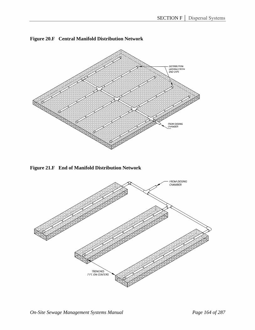
E. Pressure Distribution Systems – When the soil percolation rate or soils information indicate that the absorption rate of the soil is between 60 and 90 minutes per inch, pressurized dosing of the absorption field may be considered. This involves the installation of a septic tank followed by a pump tank fitted with a sewage effluent pump to periodically pump the sewage into an absorption field and reduce the problem of saturated soil at the point of discharge. To achieve uniform distribution, the volume of water passing out of each hole in the network during a dosing cycle must be nearly equal. To achieve this, the pressure in each segment of pipe must also be nearly equal. This is accomplished by balancing the head losses through proper sizing of the pipe diameter, hole diameter and hole spacing. Thus, approximately 75% to 85% of the total head loss incurred is across the holes in the lateral, while the remaining 15% to 25% of head loss is incurred in the networks. These usually consist of one to 3-inch (3-to 8-cm) diameter laterals, connected by a central or end manifold of larger diameter (See Figures 20.F and 21.F). The laterals are perforated at their inverts with ¼ to ½ inch (0.6 to 1.3 cm) diameter holes. The spacing between holes is 2 feet to 10 feet (0.6 to 3.0 m). 1. Pumps are used to pressurize the network, although siphons may be used if the dosing
tank is located at a higher elevation than the lateral inverts. The active dosing volume is about ten times the total lateral pipe volume. This ensures more uniform distribution since the laterals, drained after each dose, must fill before the network can become properly pressurized. (See Section E for Dosing Tank Design).
2. To simplify the design of small pressure distribution networks, refer to the tables and figures in Section O.
F. Perforated Pipe – Pressure Usage, Low Pressure Pipe Systems: 1. Pipe used for pressure carriage and distribution of effluent within lateral trenches,
mounds or other low-pressure pipe (LPP) applications shall be of at least 160 psi PVC construction. Deep hub water line shall be used.
2. Each standard section of pipe as supplied by the manufacturer shall be plainly marked, embossed or engraved showing the manufacturer’s name or hallmark, the 160 psi designation and the type of pipe material.
3. All such pipe used on an individual LPP system installation shall be of the same type. Material-mixing of PVC, polyethylene or other equivalent piping is prohibited.
4. Minimum pipe internal diameter shall be determined on a case-by-case basis, based upon system size, configuration and other factors necessary in the design of a low-pressure pipe system.
5. Pipe perforations shall run in a straight line along the bottom of the pipe. Where pre-perforated pipe is unavailable, perforations shall be hand-drilled, and deburred. Hole diameters and hole spacing shall be determined on a case-by-case basis relative to design requirements of the low-pressure pipe system.

SECTION F │ Dispersal Systems
On-Site Sewage Management Systems Manual Page 142 of 287
4) Chamber Systems
A. Chamber Systems - means a system of chambers with each chamber being a molded polyolefin plastic, arch shaped, hollow structure with an exposed bottom area and solid top and louvered sidewall for infiltration of effluent into adjoining bottom and sidewall soil areas. Chambers may be of different sizes and configurations to obtain desired surface areas. The first step in designing any sewage disposal system is to conduct a thorough site evaluation as covered in other sections of the Manual. Once the feasibility of a septic system is confirmed, the next step is to determine the appropriate size of the system as specified in the current Manual. Chamber systems may then be equivalently sized according to manufacturers’ recommendations and per approval by the Department. Chamber leaching systems provide flexibility and may be adapted to most design situations including equal distribution, serial distribution, pump-up design, cut and fill, at-grade systems and mounds. Installation instructions for various chambers will be based on specific manufacturer’s recommendations, which have been reviewed by the Technical Review Committee and approved by the Department. There must be a totally separate absorption field replacement area equivalent in size to 100% of the chamber field installed or a conventional absorption field, whichever is larger.
B. Standards for Chamber Systems - All chambers must be designed and constructed to meet the following minimum standards: 1. Metal chamber systems are prohibited. 2. Support vertical uniform loading of 600 lb/sq.ft on the top of the chamber without
damage or permanent deformation, meeting American Association of State Highway and Traffic Officials load rating H-10 (16,000 lbs/axle);
3. In non-vehicle traffic areas, chambers may be approved for installation with a final soil cover of 6 inches provided the chambers in the final installed configuration are capable of supporting a 4,000 lb/axle load without collapsing, fracturing, or breaking. The chamber must be capable of supporting a temporary construction loading of 16,000 lbs/axle (American Association of State Highway and Transportation Officials H-10 load) without collapsing, fracturing or breaking. Additional soil cover above the final grade may be used to bridge this load during construction.
4. Provide ports, slots or other similar openings on sidewalls to allow air movement and effluent access to lateral field trench sidewall absorption surfaces;
5. Interlock to allow serial installation of chambers, and be provided with acceptable end plates, caps or other necessary fittings and connectors;
6. All chambers shall be designed to accommodate at least one inspection port of a minimum internal dimension of four inches centrally located in the top of the chamber;
7. All such chambers offered for sale or use in Georgia shall bear, by imprint, stencil or other acceptable means of permanent marking, the manufacturer name and product identification number assigned to the chamber plans and specifications; this shall be located in an easily visible location on each chamber.
5) Wisconsin Mound Soil Absorption System

SECTION F │ Dispersal Systems
On-Site Sewage Management Systems Manual Page 143 of 287
The Wisconsin mound wastewater soil absorption system was developed in the early 1970's to be used on sites with specific site characteristics where in-ground gravity flow trench or bed soil absorption systems were restricted. The Wisconsin mound system has been widely accepted and incorporated in many state regulations. It is one of several systems suitable for treating and disposing of the wastewater generated in residential and commercial units and is not suited for all sites.
The objectives are to treat and dispose of the wastewater via the subsurface in an environmentally acceptable manner and to protect the public health.
The concept of an elevated on-site system for sewage disposal was developed in the 1950's (Witz, 1974). In the 1970's, significant modifications were made to overcome many system limitations (Converse et al., 1975 a, b, c,; Machmeier, 1977; Carlile et al, 1977). Figure 22.F is a cross section of a Wisconsin mound system. It consists of a septic tank, a dosing chamber and the mound. As with other soil absorption systems, the septic tank removes most of the settleable solids and is a place for liquefaction of the more easily biodegradable solids. The dosing tank contains a pump or siphon, which pressurizes a distribution network of small diameter pipe with small perforations and distributes the septic tank effluent uniformly along the length of the mound. The purpose of the mound is to accept septic tank effluent, and along with the native soil, treat and purify the wastewater to acceptable standards. The mound consists of a layer of suitable sand, aggregate, distribution system and soil cover. Originally, the Wisconsin mound system was designed for individual homes with specific soil and site limitation and with wastewater flows of less than 750 gpd (Converse et al., 1975 a, b, c; Converse 1978). As the need for disposal of wastewater on sites where below grade systems were not appropriate and for disposal of greater wastewater volumes from small communities, clusters of disposal of homes and commercial establishments increased, the demand for the Wisconsin mound system on these sites has increased. It is not unusual to see Wisconsin mound systems receiving wastewater flows in excess of 25,000 gpd. Evaluation of mounds on sites with more restrictions than currently allowed in most codes has resulted in utilizing mounds on more difficult sites. (Converse and Tyler, 1986a; 1986b). Based on the experience of siting, design and construction, concepts have been modified (Tyler and Converse, 1985; Converse and Tyler, 1987). The purpose of this Manual is to consolidate these concepts and present the latest siting, design and construction criteria of the Wisconsin mound system.
A. Siting Criteria – A designer of on-site wastewater treatment and disposal systems must have a basic understanding of water movement into and through the soil especially on more difficult sites. This understanding is based on information collected during the site evaluation. The siting of the system and loading rates can be no better than the information used. Figure 24.F shows a schematic of effluent movement within and away from mound systems under various soil profiles. Depending on the type of profile, the effluent moves away from the site vertically, horizontally or a combination of both. It should be noted that these concepts are true for all soil absorption systems. The sizing and configuration of all soil absorption systems, including the mound, is based on how the effluent moves away from the system and the rate at which it moves away from the system. Thus, the designer must predict that movement and rate of movement or the design may be flawed and the system may fail. The prediction is made based on soil and site information obtained during site evaluation.

SECTION F │ Dispersal Systems
On-Site Sewage Management Systems Manual Page 144 of 287
The siting and design concepts presented in this publication and elsewhere (Converse, et. Al. 1989, and Tyler and Converse, 1986) results in soil absorption systems that are usually long and narrow. The more restrictive the site, the narrower and longer the soil absorption system must be. If these concepts are not followed, then the system may not perform as expected. It should be noted that these concepts will not apply to all soil and site situations, as soil absorptions systems are not compatible to all sites and should not be used on such sites. Codes regulating on-site subsurface disposal of wastewater require a suitable depth of soil to treat the effluent before it reaches the limiting condition; such as bedrock or high water table, or a slowly permeable soil layer. Figure 19.F shows the relationship between the type of system that may be best suited and the location of the limiting condition beneath the ground surface, utilizing a 2 ft suitable soil separation distance. This suitable depth of unsaturated soil varies among codes but usually is between 1 and 4 ft. For the mound system, this suitable depth consists of the distance from the ground surface to the limiting condition below the ground surface, plus the depth of sand between the ground surface and the infiltrative surface within the mound (normally the aggregate/sand interface or the exposed surface of chamber units). For the at-grade system, the suitable depth is from the ground surface to the limiting condition (Converse et al., 1989). For example, if the code required 2 ft of suitable soil and the site distance was greater than two feet but less than required for an in-ground system, an at-grade system would be better suited than a mound system for the site. However, if this distance was less, then a mound system may be most appropriate. This Manual does not provide methods and procedures for describing and interpreting soil and site conditions used to determine suitability and design parameters for a Wisconsin mound. A Soil Classifier or other qualified soil evaluator should be employed to provide site descriptions and interpretations. It is best if the Soil Classifier works with the designer and installers to insure proper use of the site. Table 5.F gives soil and site criteria for the Wisconsin mound based on research and field experience. When the mound was originally developed in the 1970's, the criteria were conservative as there was very little experience with mound systems. Since that time, considerable research has been conducted on more difficult sites (Converse and Tyler, 1985, 1987). Care must be taken when using these criteria as they are for the most difficult sites utilizing on-site systems. Design configuration, loading rates and construction are very critical for the successful functioning of the systems. 1. Depth to High Water Table – High ground water table, including seasonally perched
water table, should be greater than about 10 inches beneath the ground surface. High water table is determined by direct observation and/or interpretation of soil mottling. Since it is impossible to detect soil mottles in black surface horizons, it is difficult to determine the exact location of seasonal saturation during wet periods. At some sites during wet periods, saturation may occur at the sand/soil interface at the toe of the mound as the effluent is restricted from moving away from the mound. This effluent is usually extremely low in fecal bacteria but has high nitrates and chlorides (Converse and Tyler, 1985; 1987). Under these saturated conditions, there is the possibility of leakage of this water from the toe of the mound for a few days during seasonal saturation of the soil.

SECTION F │ Dispersal Systems
On-Site Sewage Management Systems Manual Page 145 of 287
2. Depth to Bedrock – Bedrock should be classified as crevice, non-crevice semi-permeable or non-crevice impermeable. Two feet of natural soil depth is suggested for the crevice bedrock as it is assumed that very little treatment takes place in the crevice bedrock. The natural soil aids in the treatment of the effluent and the extra foot of natural soil acts as a factor of safety as the first water table that the effluent will contact may be permanent and potable. Potable water is usually separated from seasonal water table; therefore, shallower depths are required for the non-crevice bedrock as the potential for ground water contamination is much less. In the non-crevice, very slowly permeable or impermeable bedrock, the effluent flow will be horizontal. In the semi-permeable sandstones, the flow will be both vertical and horizontal.
3. Soil Permeability – Most codes have used the percolation test to size the soil absorption system. The percolation test is empirically related to the loading rate and it has been shown that the percolation test is very variable. Loading rates should be based on soil texture, structure and consistence with the percolation test, if required, to confirm morphological interpretations. This approach requires more detailed site evaluation and will be used for mound design and siting. Table 6.F gives the design soil loading rates based on morphological interpretations.
4. Slope – Mound systems on steep slopes with slowly permeable soils should be narrow to reduce the possibility of toe seepage. Slope limitation is primarily for construction safety. It is very difficult to operate equipment on such steep slopes and installers should be warned about the construction hazards.
5. Filled Sites – Fill is defined as the soil placed on a site to raise the elevation of the site. Typically, it is placed on top of the natural soil and may consist of soil with textures ranging from sand to clay or a mixture of textures. During placement soil structure is destroyed and the soil is usually compacted. Under these circumstances the permeability of the soil is reduced and variable. Thus, if a system is to be placed on the site, sufficient time must pass to allow the soil structure to develop and compaction to be reduced via warm and/or freeze/thaw activity. A more intensive soil evaluation must be done because of the variability encountered in filled sites over naturally occurring sites. Many more observation locations are generally needed for filled sites compared to non-filled sites.
6. Over Old Systems – Mounds have been successfully placed over failing in-ground soil absorption units. The soil above the system has been disturbed and must be treated as a filled site when evaluating the soil for loading rate. A more detailed evaluation of the effluent movement must be done especially if a mound is placed over a large in-ground system.
7. Flood Plain – It is not recommended to install any soil absorption system in a flood plain, drainage ways or depressions unless flood protection is provided.
8. Horizontal Separation Distances – The same separation distances between the mound and the respective site features that apply for in-ground systems should apply for the Wisconsin mounds. On sloping sites, the upslope and end distances should be measured from the upslope edge or ends of the aggregate to the respective features and the down slope distance should be measured from the down slope toe of the mound to the respective features. As with all wastewater infiltration systems on sloping sites that have primarily horizontal flow from the mound, a greater down slope horizontal

SECTION F │ Dispersal Systems
On-Site Sewage Management Systems Manual Page 146 of 287
separation distance may be appropriate to avoid weeping into a ditch or basement that may be located down slope.
9. Sites with Trees and Large Boulders – Generally, sites with large trees, numerous smaller trees or large boulders are less desirable for mound systems because of the difficulty in preparing the site. If a more desirable site is not available, the trees must be cut at ground level. The stumps should not be removed. If the tree stumps and/or boulders occupy a significant amount of the surface area, the size of the mound should be increased to provide sufficient soil to accept the effluent. The site evaluator should provide location and size information about trees and boulders.
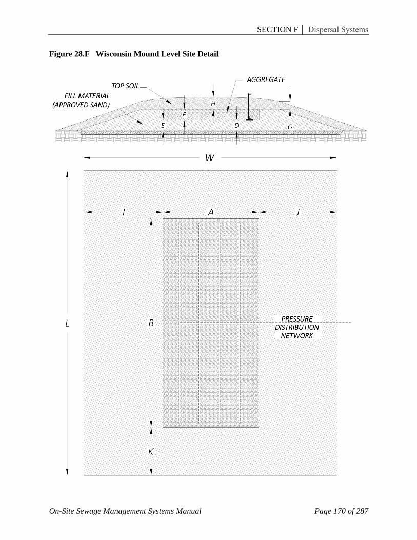
B. Mound Design Concepts – As with all soil absorption systems, a mound wastewater infiltration system must be sized and configured to match the soil and site conditions and the volume and quality of wastewater applied to it. Thus, it is imperative that the designer has sufficient information about the quality and quantity of effluent, soil and site features and understands the mound operating principles. The Soil Classifier or site evaluator must accurately estimate the design soil loading rate (Table 6.F) and determine the direction of flow away from the system (Figure 24.F) before the mound can be properly designed. The design consists of estimating the: 1) sand fill loading rate, 2) soil (basal) loading rate and 3) linear loading rate for the site. Once these three design rates are determined, the mound can be sized for the site. Figures 27.F and 28.F show a cross section and plan view of the mound on sloping and level sites, respectively, and show dimensions that must be determined. 1. Sand Fill Loading Rate – The design sand loading rate for the absorption area
(aggregate/sand interface) in Figures 27.F and 28.F is dependent upon the quality of effluent applied and the type and quality of fill material placed beneath the aggregate. The loading rate in this Manual assumes a sand is used that meets the guidelines and a typical domestic septic tank effluent quality. If commercial septic tank effluent is used, such as from restaurants, the loading rates should be reduced as the strength of the effluent may be much greater thus accelerating and intensifying the clogging of the aggregate/sand interface (Seigrest et al., 1985). If higher quality effluent is used, such as that from sand filters or aeration units, higher design loading rates may be justified. Limited experience with different qualities of effluent wastewater makes it difficult to predict long term loading rates. The purpose of the sand fill, along with the native soil, is to treat the effluent to an acceptable level. A very coarse sand will not provide adequate treatment and a very fine sand cannot be loaded at acceptable levels without severe clogging, thus resulting in mound failure. Thus, a sand must be selected that provides satisfactory treatment and allows for a reasonable loading rate. During the initial development of the mound, medium sand (USDA classification) was considered suitable for mound fill but it was soon shown that premature failure resulted for sand fill that was on the fine side of medium or was a fine sand. Bank run sand, which was classified as medium sand, was also found unsuitable, in most cases, as it was usually poorly sorted and contained a lot of fines. Currently the recommendation is to use a coarse sand with a minimum amount of fines, which appears to give acceptable treatment at an acceptable loading rate. It is also important to provide a specification that provides acceptable treatment and is available at a reasonable cost.

SECTION F │ Dispersal Systems
On-Site Sewage Management Systems Manual Page 147 of 287
Standard classifications such as USDA are not suitable as they are very broad. For example, a coarse sand may or may not be acceptable while a medium sand may be, as it depends upon a combination of various sand fractions. Figure 26.F can be used as a guide for selecting a suitable mound sand fill. Based on a sieve analysis of the total sample, the sand fill specification should fit between the ranges given in Figure 26.F. In addition, the sand fill must not have more than 20% (by wt) material that is greater than 2 mm in diameter, which can include stone, cobbles and gravel. Also, there must not be more than 5% silt and clay (<.053 mm) in the fill. This guideline is based on experience and judgment. According to USDA classification, this is a coarse sand; however, many other sands could be defined as coarse sand according USDA and not meet this guideline for mound sand fill. C-33 specification (ASTM, 1984) for fine aggregate does fit within this guideline but the coarser (>2 mm) and finer (<.053) fractions must be evaluated to make sure they meet the limits. A sand with an effective diameter (D10) of 0.15 to 0.3 and a uniformity coefficient (D60 /D10) between 4 and 6 fit within this guideline provided the coarser (>2 mm) and finer (<.053) fractions meet the guideline. The recommended design loading rate for a sand fill that meets this guideline (Figure 26.F) is 1.0 gpd/ft2 if the effluent is a typical domestic septic tank effluent. This assumes that there is a factor of safety provided. It assumes, for design purposes, that a home generates 75 gpcd with two people per bedroom or 150 gallons per bedroom per day. Based on a number of studies, the average quantity of effluent generated per day is about 45 gpcd (Witt et al. 1974). Converse and Tyler, 1987, found, based on water meter reading in the home, that the wastewater generated in the home averaged 47% of design with a range of 29 to 82%. If water meter readings are used for design purposes, the design sand loading rage should be reduced accordingly. Systems loaded to design without appropriate factor of safety will fail due to overloading. Similar procedures should be followed for commercial establishments including lower loading rates due to the higher strength effluent as discussed above.
2. Basal Loading Rates – The basal area (sand/soil interface in Figures 27.F and 28.F) is the area enclosed by the B (A+I) for sloping sites (Figure 27.F) and B (A+I+J) for level sites where J equals I for level sites (Figure 28.F). It is sized according to the long-term infiltration rate (assuming a clogging mat forms) for the soil at the sand/soil interface (Table 6.F). This interface receives relatively clean effluent since the wastewater has already passed through sand and normally a clogging mat does not develop at this interface, thus over sizing the basal area. Additional over sizing usually results because the distance required to maintain a 3:1 mound side slope is greater than that required for the infiltration basal width except for maybe the very slowly permeable soils or the very steep sites.
3. Linear Loading Rate – The linear loading rate is defined as the amount of effluent (gallons) applied per day per linear foot of the system (gpd/1f). The design linear loading rate is a function of effluent movement rate away from the system and the direction of movement away from the system (horizontal, vertical or combination, Figure 24.F). If the movement is primarily vertical, then the linear loading rate is not as critical as if the flow is primarily horizontal. Other factors such as gas transfer from beneath the absorption area suggests that the absorption area width be relatively small

SECTION F │ Dispersal Systems
On-Site Sewage Management Systems Manual Page 148 of 287
(Tyler et al, 1986). It is difficult to estimate the linear loading rate for a variety of soil and flow conditions, but based on the authors’ experience, “good estimates” can be given. If the flow away from the system is primarily vertical, then the linear loading rate can be high, but should be in the range of 8 to 10 gpd/lf otherwise; the absorption area is excessively wide, especially for the slower permeable soils such as silt loams. However, if the flow is shallow and primarily horizontal then the linear loading rate should be in the range of 3 to 4 gpd/1f. This approach will result in long and narrow systems.
4. Dimensioning the Mound – Figures 27.F and 28.F show the cross section and plan view of the mound for sloping and level sites. The dimensions are based on the site conditions and loading rates that are site-specific. a. Absorption Area Width (A) – The width of the absorption area is a function of
linear loading rate and the design loading rate of the sand fill selected. b. Absorption Area Length (B) – The length of the absorption area is a function of the
design loading rate (gpd) and the width of the absorption area (A). c. Basal Length and Width – For sloping and level sites the basal width is (I + A) and
(I + J + A), respectively, and the basal length is (B). The width is determined by the linear loading rate and the infiltration rate for the surface soil horizon (sand/soil interface).
d. Slope Width (I) and (J) – For sloping sites the down slope width (I) is a function of the basal width (A + I) and the absorption area width (A). Upslope width (J) is a function of the 3:1 recommended side slope and is dependent upon the depth of the mound and the slope of the site. A typical dimension is 8 to 10 ft. but can be greater or less depending on the desired mound side slope and the slope of the site. For level sites the slope widths (J) and (I) are equal and are a function of the required basal width or the minimum recommended mound side slopes, whichever is greater.
e. Slope Length (K) – The slope length (K) is a function of the mound depth and the desired mound end slope. The recommended end slope is 3:1 but can be greater. Steeper mound side slopes are not recommended as they can become a safety hazard if the mound is to be mowed. Typical dimensions are 10 - 15 ft.
f. Depth (D) – This depth is a function of the suitable soil separation depth required by code and the depth of the limiting condition from the soil surface. If the required separation distance from the absorption surface to the limiting condition, such as bedrock or high water table, is 3 ft and the limiting condition is 1 ft beneath the ground surface, then (D) must be a minimum of 2 ft.
g. Depth (E) – This depth is a function of the surface slope and width of the absorption area (A) as the absorption area must be level.
h. Depth (F) – This depth is at least 9 in. with a minimum of 6 in. of aggregate beneath the distribution pipes, approximately 2 in. for the distribution pipe and 1 in. of aggregate over the pipe.
i. Depth (G) and (H) – The recommended depth for (G) and (H) is 12 in. and 18 in., respectively, for the colder climates and 6 in. and 12 in. for the warmer climates. The (H) depth must be greater than the (G) depth to promote runoff on the top of the mound.

SECTION F │ Dispersal Systems
On-Site Sewage Management Systems Manual Page 149 of 287
5. Mound Cover – The purpose of the soil cover is to provide a medium for a vegetative cover and protection. Any soil material that will support a suitable vegetative cover is satisfactory. This material may range from a sandy loam to a clay loam. A sand does not support a suitable vegetative cover. A heavier textured soil will promote more precipitation runoff than a lighter texture soil and will also hold more moisture during dry periods thus reducing the drying out of the vegetative cover on the top and sides.
6. Effluent Distribution Network – The mound system is designed with a pressure distribution network to distribute the effluent along the length of the mound. Gravity distribution will not distribute it uniformly but drops it in one or two locations (Converse, 1974), Machmeier and Anderson, 1988). Otis, 1981, gives design criteria and examples for pressure distribution.
7. Observation Tubes – It is essential for all soil absorption systems to have observation wells extending from the infiltrative surface (aggregate/sand interface) to or above the ground surface for the purposes of observing the performance of the infiltrative surface. The tubes provide an easy access to the infiltrative surface to see if ponding is occurring. Tubes should be placed at 1/6, ½ and 5/6 points along the length of the absorption area. All observation tubes must be securely anchored. Figure 25.F illustrates three methods of anchoring the observation tubes. Slip or screw caps can be used. If brought to the surface, they should be recessed slightly as lawn mowers may destroy the caps. If brought above ground surface, schedule 40 PVC pipe is required.
C. Mound Performance – The first Wisconsin mound system of the current design was
installed in 1973. In Wisconsin alone there are over 12,000 mound systems. Many other states have adopted the technology. Proper siting of all soil absorption systems, including the mound, is essential otherwise the system may not function as planned.
In Wisconsin the mound system has a success rate of over 95% (Converse and Tyler, 1986). This success rate is due in part to a very strong educational program relating to siting, design and construction.
A mound can fail either at the 1) aggregate/sand interface due to a clogging mat or 2) at the sand/soil interface due to the inability of the soil to accept the effluent. Converse and Tyler (1989) discuss the mechanisms that may cause failure and methods to rectify the problems.
D. Mound Construction – A construction plan for any on-site system is essential. A clear understanding between the site classifier, designer, contractor and inspector is critical if a successful system is installed. It is important that the contractor and inspector understand the principles of operation of the mound system before construction commences otherwise the system may not function as intended. It is also important to anticipate and plan for the weather. It is best to be able to complete the mound before it rains on it. The tilled area and the absorption area must be protected from rain by placing sand on the tilled area and aggregate on the absorption area prior to rain. The following points are essential: 1. The mound must be placed on the contour. Measure the average ground elevation (prior
to tillage) along the upslope edge of the absorption area, which will be used to determine the elevation of the absorption area.

SECTION F │ Dispersal Systems
On-Site Sewage Management Systems Manual Page 150 of 287
2. Grass, shrubs and trees must be cut close to the ground surface and removed from the site. In wooded areas with excessive litter, it is required to rake the majority of it from the site.
3. Locate the entrance of the force main into the mound. It is required to bring it into the center on the upslope side. If it must be brought in from the down slope side, especially on sites with horizontal flow, it must be brought in perpendicular to the side of the mound with minimal disturbance to the down slope area.
4. The mound site must be tilled when at the proper moisture level. The proper moisture level to a depth of 7 to 8 in. must be such that the soil will crumble and not take on a wire form when rolled between the palms. The purpose is to roughen up the surface and incorporate most of the vegetation. This can be done with a mold board plow, chisel plow or chisel teeth mounted on a tool bar attached to the bucket of a backhoe. The backhoe bucket teeth are not satisfactory and must not be used. Rototillers are prohibited on structured soils but can be used on unstructured soils such as sands. However, they are not recommended. Tilling along the contour is required. Protect the tilled area from rain by placing a layer of sand on it.
5. If a platy structure is present in the upper horizons, it is necessary to till it. Normally, the chisel teeth mounted on a backhoe bucket is preferred as it can be used to till around stumps and till deeper than the other methods. Stumps are not to be removed but tilled around. If there is an excessive number of stumps or boulders, then the basal area should be enlarged or another site found.
6. Once the site is tilled, a layer of sand should be placed before it rains on the tilled area. Placement of the sand should be such as not to rut up or compact the tilled area. All work shall be done from the upslope side so as not to compact the down slope area especially if the effluent flow is horizontal away from the system. Sand should be placed with a backhoe or moved around the site with a track type tractor. Wheeled tractors will rut up the site.
7. Place the proper depth of sand then form the absorption area with the area bottom being level. Protect this infiltrative area from rain by placing the aggregate prior to rain.
8. Place a suitable aggregate to the desired depth in the area provided. The aggregate must be clean and sound and not deteriorate. Limestone is not recommended.
9. Place the pressure distribution pipe and connect it to the force main and cover with 1 in. of aggregate.
10. Cover the aggregate with a geotextile synthetic fabric. 11. Place a minimum of 6 inches of suitable soil cover on the sides of the mound and to the
prescribed depth on the top of the mound. 12. Final grade the mound and area with light weight equipment so surface water moves
away from the mound and does not accumulate on the upslope side of the mound. 13. Seed and mulch the entire exposed area to avoid erosion. Landscape it with shrubs and
plants so that it fits into the surrounding area. The top of the mound may be somewhat dry during the summer months and the down slope toe may be somewhat moist during the wet seasons (Schutt, 1981).

SECTION F │ Dispersal Systems
On-Site Sewage Management Systems Manual Page 151 of 287
6) Minimum Criteria for Pressurized Subsurface Absorption Fields Utilizing Emitters
Subsurface systems utilizing emitters may be used in lieu of conventional or other alternative absorption fields. The number of subsurface land disposal systems continues to increase as sites are developed with conditions unsuitable for many other wastewater treatment systems. This document provides guidelines and criteria for the planning, design and operation of pressurized subsurface absorption fields utilizing emitters, commonly referred to as drip irrigation.
The term drip irrigation as used in this document refers to the treatment of wastewater by irrigation below the land’s surface. These systems are designed and operated so that there is no direct discharge of wastewater to the land’s surface. The irrigated wastewater transpires to the atmosphere and enters the groundwater through infiltration and percolation. Organic constituents in the wastewater are consumed or stabilized by soil bacteria. Organic and ammonia nitrogen are taken up by plants, nitrified by soil bacteria, lost to the atmosphere through denitrification, leached into the groundwater or stored as soil nitrogen in the site biota. Phosphorous and many metal constituents are absorbed into soil particles and taken up by plants. Properly designed and operated wastewater irrigation systems produce a percolate water of high quality and thus protect ground and surface waters.
The criteria in this document only apply to domestic wastewater. The drip irrigation technology is based on maintaining aerobic conditions in the soil. Therefore, dosing and resting cycles must be established as part of the plan of operation and management. In order for systems to maximize nitrogen removal and prevent nitrate nitrogen from contaminating the groundwater, the installation of the subsurface dripper lines should be within the root zone of the cover vegetation. The on-site wastewater system will consist of aerobic pretreatment followed by a subsurface distribution system utilizing emitters to distribute a controlled flow of wastewater to the soil. Drip irrigation systems must be capable of providing an equal flow distribution of wastewater effluent applied throughout the application field (s) at a predetermined application rate. It is imperative that all drip irrigation systems maintain uniform and accurate control of the effluent emission rates. Equipment must be provided that will identify and record any fluctuations in the wastewater flow through the system. All equipment proposed for use must be certified and warranted by the manufacturer that it has been tested for use with wastewater. A drip irrigation system may be sold as a complete package. All prepackaged systems must be approved by the Department prior to sale in the state of Georgia. A state of Georgia Registered Engineer must design drip irrigation systems designed on a site-specific basis. A. Design Criteria:
1. Aerobic Pretreatment – The drip emitter system shall be preceded by a pretreatment process designed to reduce the wastewater biological oxygen demand (BOD5) to a maximum concentration of 25 milligrams per liter (mg/l) and total suspended solids (TSS) concentration to a maximum of 30 milligrams per liter (mg/l). The aerobic pretreatment process must be reviewed by Technical Review Committee and approved by the Department.
2. Dosing Tanks: a. The dosing chamber shall meet all requirements established in the On-Site Manual
and have a minimum capacity equal to the 24-hour waste flow from the facility

SECTION F │ Dispersal Systems
On-Site Sewage Management Systems Manual Page 152 of 287
served. The dosing chamber shall be equipped with an audible and visible alarm that indicates a high water level or loss of power to the pump or controls.
b. Time dosing shall be utilized to dose the absorption field or zones. The frequency of dosing shall be based on the soil’s hydraulic loading rate and the design flow. Fields or zones shall be time dosed to insure the total 24-hour wastewater effluent flow is applied in a 24-hour period.
c. All new systems must be equipped to detect a plus (+) or minus (-) 10% change in flow rate in the disposal field due to clogging of the filters, a force main break, emitter clogging, leaks in the field lines and a flush valve failure.
3. Subsurface Absorption Field – All components of the subsurface absorption system must be reviewed by Technical Review Committee and approved by the Department for use in the state of Georgia. Any component changes will require a review and approval prior to use. The emitter subsurface absorption field system must meet the following requirements: a. Dose the entire absorption field or zone equally. The length of each distribution line
shall not exceed the manufacturers’ specifications to insure equal application of wastewater effluent from each emitter. No more than a 10 percent variation in flow between individual emitters anywhere within a separately dosed zone, including drain back is acceptable.
b. Drain back - When slopes exceed five percent, check valves or other approved means shall be used in the supply and return manifolds to minimize drainage into the lowest area of the zone.
c. Emitter line and emitters must be warranted by the manufacturer for wastewater application and approved by the Department. Emitter lines must be identified with the manufacturer’s name and product number. Emitters shall be pressure or non-pressure compensating emitters. Emitters shall be spaced either one foot or two feet apart within the emitter line.
d. The wastewater effluent must be filtered to emitter manufacturer’s specifications to insure the proper operation of the distribution system.
e. The filtration system shall be automatically self-cleaning and the filter residue and backwash returned to the treatment unit, with provisions made to minimize disturbance of any solids settling fin the chamber (ex. Provide baffles or comparable intake structure in septic tank to minimize solids re-suspension in the inlet compartment).
f. Typically, separation between emitter line laterals will be two feet. However, a one-foot separation between emitter line laterals may be allowed without a reduction in absorption field area. Lateral spacing of three feet or greater is required on slopes exceeding 20%.
g. Individual emitter lines shall be designed and installed level, following the naturally occurring ground contour, with a maximum allowable variance of plus (+) or minus (-) six (6”) inches within any linear one hundred (100’) foot segment.
SECTION F │ Dispersal Systems
On-Site Sewage Management Systems Manual Page 153 of 287
h. Emitter lines shall be installed in the root zone of the cover vegetation, a depth of 8 to 12 inches from the original undisturbed ground surface, and /or shall be a minimum of eight inches from the ground surface.
i. A system for automatic flushing of distribution lines should be provided and performed according to manufacturer’s recommendations, at a minimum on a bi-monthly basis. Velocities must be a minimum of two feet per second at the distal end of each drip irrigation line or return line during the flushing operation.
j. All materials shall meet applicable ASTM standards, be chemical resistant, and be approved for wastewater usage.
k. Equipment susceptible to freezing must be adequately protected to prevent freezing.
l. There must be a totally separate absorption field replacement area equivalent in size to 100% of the emitter field installed or for a conventional absorption field, whichever is larger.
m. A vibratory plough, ditch witch or backhoe may be utilized for drip line installation. 4. Site Criteria:
a. The minimum horizontal setback requirements established in the On-Site Sewage Management System Manual, Chapter 511-3-1-.07 (3) shall be met.
b. Required vertical separation requirements shall be measured from the bottom of the drip tubing or trench bottom, whichever is greater.
c. There shall be a minimum vertical separation of 12 inches between the bottom of the absorption field and any seasonal groundwater table, rock or impervious soil strata. Greater vertical separation may be required if a site is hydraulically limited as determined by soil investigations by the Soil Classifier or design engineer.
d. Areas subject to surface water ponding shall not be considered for installation. 5. Absorption Field Sizing:
a. Table 7.F shall be used in determining the hydraulic loading rate for subsurface absorption fields utilizing emitters. The design hydraulic loading rate shall be based on the most hydraulically limiting, naturally occurring soil horizon within one (1’) foot of the drip line or trench bottom, whichever is greater.
b. Facilities utilizing approved aerobic pretreatment shall not have a waste stream that exceeds a fat, oil and grease content of 25mg/l prior to soil application.
c. In calculating the number of square feet for the absorption field, the design daily sewage flow shall be divided by the maximum hydraulic loading rate determined by the Table 7.F. In calculating the minimum linear length of drip emitter line required, the total square footage of the absorption field shall be divided by two feet.
d. There shall be a totally separate area available for 100% replacement of the emitter absorption field or a conventional absorption field, whichever is larger.
6. Application Requirements – The following information shall be submitted to the local county health department for evaluation and approval in order to obtain a construction

SECTION F │ Dispersal Systems
On-Site Sewage Management Systems Manual Page 154 of 287
permit for an on-site sewage management system utilizing pressurized subsurface absorption fields with emitters: a. A Level 4 soil investigation including detail with soil horizons identified and
hydraulic loading rates determined for each horizon. b. A site plan at a minimum scale of 1 inch to 40 feet including; topography with two
feet contour changes and soil types overlaid; house or facility location scaled with driveways, sidewalks, parking, and other structures shown; location of utilities, wells, water bodies or courses and easements.
c. Sewage system must be scaled on site plan including; pretreatment unit, drip line (wastewater approved), force main, return line, manifolds, location of check valves and air vents.
d. System Design Criteria including; type of pretreatment, sewage flow rate, absorption line calculation, pump size (make and model #), and pipe sizes identified (schedule 40).
e. Type of emitter tubing (manufacturer and product # - wastewater approved). f. A manufacturer certified system design approved by the Department or a state of
Georgia Registered Engineer system design is required. A state of Georgia Registered Engineer shall design systems with a design sewage flow in excess of 2,000 gallons per day.
g. Site plans shall bear the signature of the designer and the following statement: I certify this sewage system design meets the minimum design requirements established by the Georgia Department of Public Health’s Manual for On-Site Sewage Management Systems.
7. Operation and Maintenance - Satisfactory operation and maintenance of pressurized subsurface absorption fields are necessary to safeguard the health of the user and the public. a. A three-year initial service policy shall be furnished to the user by the manufacturer
or licensed distributor and shall be included in the original purchase price. This policy shall provide:
(1) A minimum of 6 inspection/service visits (scheduled once every six months over the three-year period), during which electrical, mechanical, and other applicable components are inspected, adjusted, serviced and/or replaced.
(2) Emergency service shall be available within no more than two days following a request. The owner and local county health authority shall be notified immediately in writing of any improper operation observed which cannot be corrected at the time of the service call and the estimated date of correction.
(3) A clearly visible, permanently attached label or plate, giving instructions for obtaining service, shall be placed at the visual alarm signal.
b. An owner’s manual shall be provided by the manufacturer or licensed distributor to the facility owner.
c. Facility owners shall be offered a continuing service contract.
SECTION F │ Dispersal Systems
On-Site Sewage Management Systems Manual Page 155 of 287
d. Facilities with a design flow in excess of 2,000 gallons per day shall submit to the local health authority a Plan of Operation and Management. The plan must address wastewater application rates, drip field cycling, monitoring requirements, maintenance schedules and all other information necessary for successful operation.
7) Guidelines for domestic wastewater application for absorption fields designed for Class I effluent
A. Systems producing a Class I effluent quality are allowed a vertical separation distance of 12 inches between the bottom of the absorption trench and any restrictive horizon with no reduction in absorption field size.
B. Systems producing a Class I effluent quality are allowed an absorption field reduction provided the restrictive horizon is a minimum of 24 inches below the bottom of the absorption trench.
C. Maximum absorption field reduction shall be based on the standards established through the Technical Review committee as illustrated in Table 8.F.
D. When a Class I effluent system is used in conjunction with an absorption field bed design, timed dosing of the effluent shall be utilized to dose the absorption field. The frequency of dosing shall be based on the soil’s hydraulic conductivity and the design flow. The absorption field bed shall be time dosed in a manner that uniformly distributes the effluent across the entire bed with no more than a 10% variation in flow. The absorption field shall be time dosed to ensure the expected 24-hour effluent flow is applied in a 24-hour period.
E. The required absorption field area shall be based on the most hydraulically limiting soil horizon in contact with the infiltrative surface of the absorption field sidewall, bottom and extending for a distance one (1’) foot below the absorption field.
SECTION F │ Dispersal Systems
On-Site Sewage Management Systems Manual Page 156 of 287
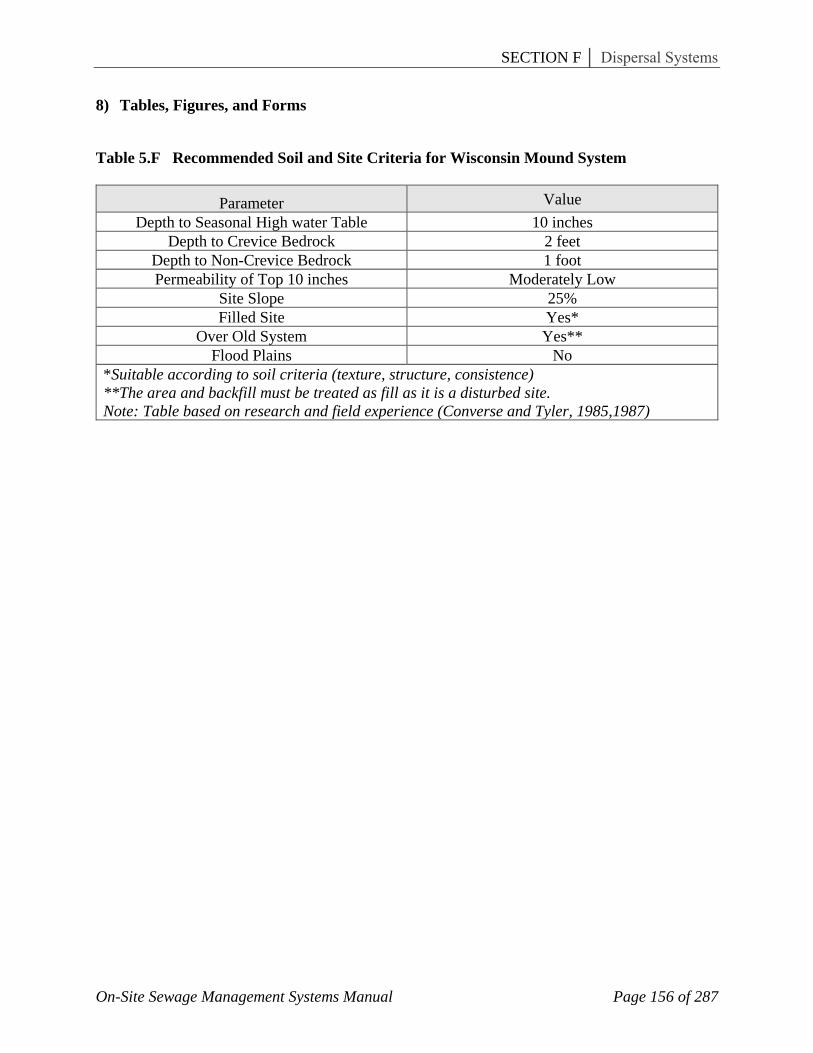
8) Tables, Figures, and Forms
Table 5.F Recommended Soil and Site Criteria for Wisconsin Mound System
Parameter Value Depth to Seasonal High water Table 10 inches
Depth to Crevice Bedrock 2 feet Depth to Non-Crevice Bedrock 1 foot Permeability of Top 10 inches Moderately Low
Site Slope 25% Filled Site Yes*
Over Old System Yes** Flood Plains No
*Suitable according to soil criteria (texture, structure, consistence) **The area and backfill must be treated as fill as it is a disturbed site. Note: Table based on research and field experience (Converse and Tyler, 1985,1987)
SECTION F │ Dispersal Systems
On-Site Sewage Management Systems Manual Page 157 of 287
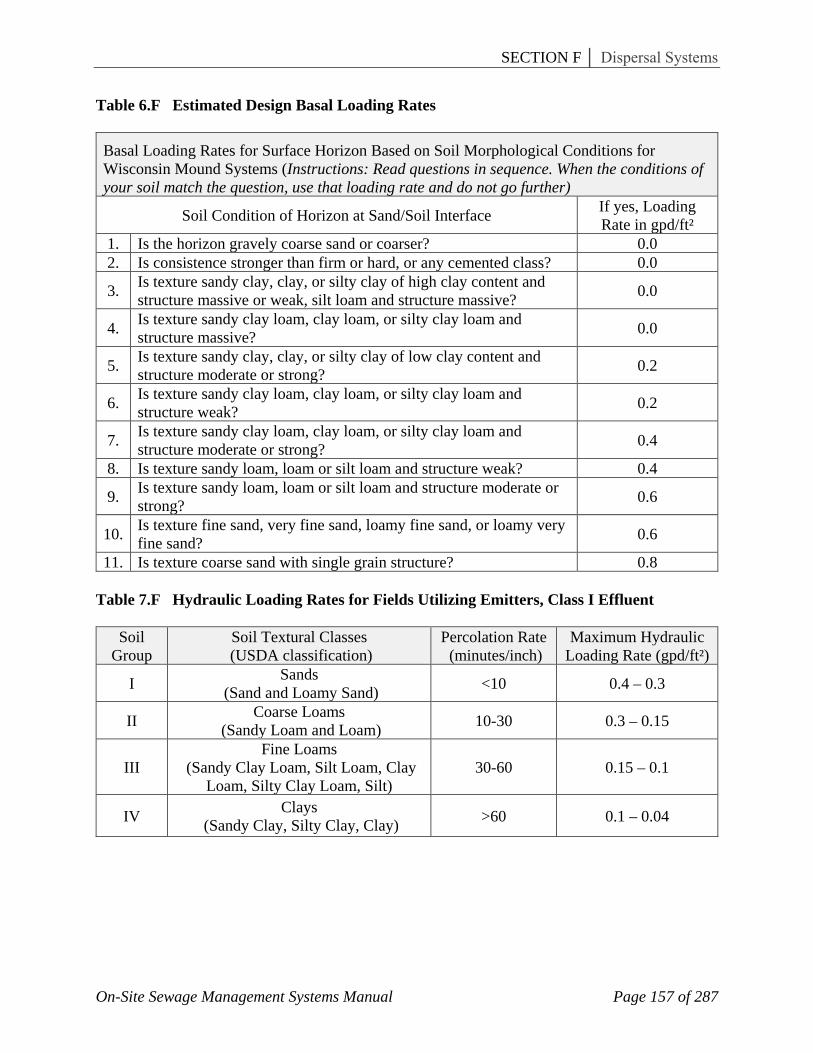
Table 6.F Estimated Design Basal Loading Rates
Basal Loading Rates for Surface Horizon Based on Soil Morphological Conditions for Wisconsin Mound Systems (Instructions: Read questions in sequence. When the conditions of your soil match the question, use that loading rate and do not go further)
Soil Condition of Horizon at Sand/Soil Interface If yes, Loading Rate in gpd/ft²
1. Is the horizon gravely coarse sand or coarser? 0.0 2. Is consistence stronger than firm or hard, or any cemented class? 0.0
3. Is texture sandy clay, clay, or silty clay of high clay content and structure massive or weak, silt loam and structure massive? 0.0
4. Is texture sandy clay loam, clay loam, or silty clay loam and structure massive? 0.0
5. Is texture sandy clay, clay, or silty clay of low clay content and structure moderate or strong? 0.2
6. Is texture sandy clay loam, clay loam, or silty clay loam and structure weak? 0.2
7. Is texture sandy clay loam, clay loam, or silty clay loam and structure moderate or strong? 0.4
8. Is texture sandy loam, loam or silt loam and structure weak? 0.4
9. Is texture sandy loam, loam or silt loam and structure moderate or strong? 0.6
10. Is texture fine sand, very fine sand, loamy fine sand, or loamy very fine sand? 0.6
11. Is texture coarse sand with single grain structure? 0.8 Table 7.F Hydraulic Loading Rates for Fields Utilizing Emitters, Class I Effluent
Soil Group
Soil Textural Classes (USDA classification)
Percolation Rate (minutes/inch)
Maximum Hydraulic Loading Rate (gpd/ft²)
I Sands (Sand and Loamy Sand) <10 0.4 – 0.3
II Coarse Loams (Sandy Loam and Loam) 10-30 0.3 – 0.15
III Fine Loams
(Sandy Clay Loam, Silt Loam, Clay Loam, Silty Clay Loam, Silt)
30-60 0.15 – 0.1
IV Clays (Sandy Clay, Silty Clay, Clay) >60 0.1 – 0.04

SECTION F │ Dispersal Systems
On-Site Sewage Management Systems Manual Page 158 of 287
Table 8.F Absorption Field Sizing Coefficients for Class I Effluent Systems This chart correlates (approx.) percolation rates, soil texture and infiltration rates for the purpose of absorption field sizing for approved systems in Georgia producing a Class I effluent for domestic wastewater application.
Percolation Rate
Minutes/Inch
Soil Texture Classes (USDA classification)
Infiltration Rate Bed Absorption Field
gallons/day/ft²
Infiltration Rate Trench Absorption Field
gallons/day/ft² Depth to Limiting Horizon
2 ft. 1 ft. 2 ft. 1 ft. 5
Group I – Sand: (Sand and Loamy
Sand)
1.31 0.97 1.6 1.2 10 1.18 0.71 1.5 0.91 15 1.09 0.61 1.4 0.79 20 1.0 0.59 1.3 0.71 25 0.92 0.54 1.2 0.65 30
Group II – Coarse Loams:
(Sandy Loam and Loam)
0.82 0.50 1.1 0.6 35 0.75 0.47 1.0 0.57 40 0.67 0.45 0.9 0.54 45 0.63 0.42 0.85 0.5 50 0.59 0.37 0.8 0.48 55 0.55 0.35 0.75 0.46 60
Group III – Fine Loams:
(Sandy Clay Loam, Silt Loam, Clay Loam, Silty
Clay Loam, Silt)
0.51 0.34 0.7 0.45 65 0.47 0.33 0.65 0.43 70 0.43 0.32 0.6 0.42 75 0.39 0.31 0.55 0.41 80 0.36 0.31 0.5 0.41 85 0.32 0.30 0.45 0.4 90 0.28 0.30 0.4 0.39 95 N/A N/A 0.39 0.39 100
Group IV – Clays: (Sandy Clay, Silty
Clay, Clay)
N/A N/A 0.385 0.38 105 N/A N/A 0.38 0.38 110 N/A N/A 0.375 0.38 115 N/A N/A 0.37 0.37 120 N/A N/A 0.365 0.37
1) Systems producing a Class I effluent quality are allowed a vertical separation distance of
12 inches between the bottom of the absorption trench and any restrictive horizon with no reduction in absorption field size.
2) Systems producing a Class I effluent quality are allowed an absorption field reduction provided the restrictive horizon is a minimum of 24 inches below the bottom of the absorption trench.
3) Maximum absorption field reduction shall be based on the standards established through the Technical Review committee as illustrated in Table 8.F.

SECTION F │ Dispersal Systems
On-Site Sewage Management Systems Manual Page 159 of 287
4) When a Class I effluent system is used in conjunction with an absorption field bed design, timed dosing of the effluent shall be utilized to dose the absorption field. The frequency of dosing shall be based on the soil’s hydraulic conductivity and the design flow. The absorption field bed shall be time dosed in a manner that uniformly distributes the effluent across the entire bed with no more than a 10% variation in flow. The absorption field shall be time dosed to ensure the expected 24-hour effluent flow is applied in a 24-hour period.
5) The required absorption field area shall be based on the most hydraulically limiting soil horizon in contact with the infiltrative surface of the absorption field sidewall, bottom and extending for a distance one (1’) foot below the absorption field.

SECTION F │ Dispersal Systems
On-Site Sewage Management Systems Manual Page 160 of 287
Table 9.F Percolation Coefficient Calculations for Non-Residential Facilities
Percolation Rate
minutes/inch (t)
Square root of time (√𝑡𝑡)
ft²/gallon
(multiply)
(√𝑡𝑡/5)
gallon/ft² (divide)
(5/√𝑡𝑡)
Percolation Rate
minutes/inch (t)
Square root of time (√𝑡𝑡)
ft²/gallon
(multiply)
(√𝑡𝑡/5)
gallon/ft² (divide)
(5/√𝑡𝑡)
5 2.236 0.447 2.236 65 8.062 1.612 0.620 10 3.162 0.632 1.581 70 8.367 1.673 0.598 15 3.873 0.775 1.291 75 8.660 1.732 0.577 20 4.472 0.894 1.118 80 8.944 1.789 0.559 25 5.0 1.0 1.0 85 9.220 1.844 0.542 30 5.477 1.095 0.913 90 9.487 1.897 0.527 35 5.916 1.183 0.845 95 9.747 1.949 0.513 40 6.325 1.265 0.791 100 10.0 2.0 0.500 45 6.708 1.342 0.745 105 10.247 2.049 0.488 50 7.071 1.414 0.707 110 10.488 2.098 0.477 55 7.416 1.483 0.674 115 10.724 2.145 0.466 60 7.746 1.549 0.645 120 10.954 2.191 0.456
Note: Effluent BOD and TSS levels must be lowered to 200 mg/l or below before application to drainfield. Public Health Services Formula C = 5/√𝑡𝑡
Table 10.F Residential Trench Absorption Field Sizing
Percolation Rate (minutes/inch)
Absorption Area per Bedroom (ft²)
Percolation Rate (minutes/inch)
Absorption Area per Bedroom (ft²)
5 125 65 345 10 165 70 355 15 190 75 365 20 210 80 370 25 230 85 375 30 250 90* 380 35 265 95* 385 40 280 100* 390 45 300 105* 395 50 310 110* 400 55 325 115* 405 60 335 120** 410
*Note: For sites less than 3 acres in size, soil horizons that exceed a percolation rate of 90 minutes per inch shall not be considered for installation of a conventional on-site sewage management system. **Note: For sites of 3 acres or more in size, soil horizons that exceed a percolation rate of 120 minutes per inch shall not be considered for installation of a conventional on-site sewage management system.
SECTION F │ Dispersal Systems
On-Site Sewage Management Systems Manual Page 161 of 287
Figure 15.F Distribution Box System Installation Example
Figure 16.F Level Field Installation Example
Figure 17.F Serial System Installation

SECTION F │ Dispersal Systems
On-Site Sewage Management Systems Manual Page 162 of 287
Figure 18.F Alternating Drainfields with Diversion Valve

SECTION F │ Dispersal Systems
On-Site Sewage Management Systems Manual Page 163 of 287
Figure 19.F Trench Installation Examples
SECTION F │ Dispersal Systems
On-Site Sewage Management Systems Manual Page 164 of 287
Figure 20.F Central Manifold Distribution Network
Figure 21.F End of Manifold Distribution Network

SECTION F │ Dispersal Systems
On-Site Sewage Management Systems Manual Page 165 of 287
Figure 22.F Wisconsin Mound General Diagrams
Figure 23.F Wisconsin Mound vs. Area Fill Mound Detail

SECTION F │ Dispersal Systems
On-Site Sewage Management Systems Manual Page 166 of 287
Figure 24.F Effluent Movement – Wisconsin Mound

SECTION F │ Dispersal Systems
On-Site Sewage Management Systems Manual Page 167 of 287
Figure 25.F Observation Tube Detail

SECTION F │ Dispersal Systems
On-Site Sewage Management Systems Manual Page 168 of 287
Figure 26.F Sieve Analysis for Acceptable Fill Material
Sand
Fill
Spe
cific
atio
ns:
<
20%
gre
ater
than
2 m
m
<
5% sm
alle
r tha
n 0.
053
mm
pl
us:
1.
Tota
l Sam
ple
siev
e an
alys
is
fits p
refe
rabl
y be
twee
n th
e so
lid li
nes.
Perm
issi
ble
to th
e da
shed
line
. or
or
2.
Effe
ctiv
e di
amet
er:
D10
= 0
.15
to 0
.30
mm
C
oeff
icie
nt o
f Uni
form
ity:
D
60/D
10 =
4 to
6

SECTION F │ Dispersal Systems
On-Site Sewage Management Systems Manual Page 169 of 287
Figure 27.F Wisconsin Mound Sloping Site Detail
SECTION F │ Dispersal Systems
On-Site Sewage Management Systems Manual Page 170 of 287
Figure 28.F Wisconsin Mound Level Site Detail
SECTION F │ Dispersal Systems
On-Site Sewage Management Systems Manual Page 171 of 287
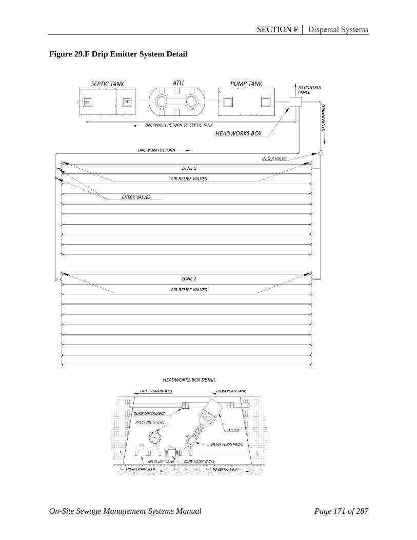
Figure 29.F Drip Emitter System Detail

SECTION F │ Dispersal Systems
On-Site Sewage Management Systems Manual Page 172 of 287
Form 5.F Wisconsin Mound System Worksheet
Wisconsin Mound System Worksheet (refer to Figures 27.F and 28.F)
Parameter Value 1. Determine design flow rate (gallons/day) 2. Determine the basal loading rate (gallons/day/square foot)
(This information must be provided by a qualified Soil Classifier)
3. Determine the linear loading rate (gallons/day/linear foot) Note: the size and configuration of the mound is based on how the effluent moves away from the system and the rate at which it moves away from the system. • Good soil structure, good permeability – vertical flow 8-10 gpd/lf • Poor soil structure, slow permeability – horizontal flow 3-4 gpd/lf (This information must be provided by a qualified Soil Classifier)
4. Sand fill design loading rate – 1.0 gpd/ft² (A Soil Classifier must certify the fill material as meeting the requirements in the Manual)
5. Determine the absorption area width (A), where: A = linear loading rate / sand fill loading rate
6. Determine the absorption area length (B), where: B = design flow rate / linear loading rate
7. Determine the basal width (A + I), where: A + I = linear loading rate / basal loading rate
8. Determine mound fill depth (D), where: D = 24” – (depth to shallow water table from original ground surface) (Note: Code requires 2 feet of separation from bottom of absorption trench/bed and seasonal high water table.)
9. Determine mound fill depth (E), where: E = D + (% slope in area of mound footprint) A
10. Determine mound depths (F), (G), and (H), where: F = absorption trench/bed aggregate depth, and G = fill cover depth, and H = fill cover depth + top soil depth
11. Determine mound upslope width (J), where: J = 3 (D + F + G) (Note: A maximum mound side slope of 3 to 1 is required)
12. Determine mound end-slope length (K), where: K = 3 ( (D + E) / 2 + F + H))
13. Determine downslope width (I), where: I = 3 (E + F + G) Note: Compare (I) with calculation from step 7. Use the largest number for downslope width. A maximum mound side slope of 3 to 1 is required)
14. Determine overall mound length (L) and width (W), where: L = B + 2K, and W = A + I + J

SECTION F │ Dispersal Systems
On-Site Sewage Management Systems Manual Page 173 of 287
Form 6.F Engineered Site Plan Checksheet
GEORGIA DEPARTMENT OF PUBLIC HEALTH OSSMS Engineered Site Plan Checksheet
A site plan may be required when more information and detail is needed to determine compliance with the regulations. Sites with marginal soil conditions, restrictive topograpghic features or other factors that limit the amount of suitable area available for the installation and replacement of an on-site sewage management system may require an engineered plan from a State Registered Engineer. The following requirements will determine compliance with the state regulations. The site plan must include the following: Site plan drawn to a minimum 1” to 40’ scale. Topographic delineations on 2-foot contours showing existing and/or finish grades. Location and dimensions of residence (s) or building (s), including setback distances from
property lines. Location of driveway (s), paved areas, pools, and other structures. Location of underground utility lines, water lines or wells (on or within 100 ft. of the
property). Location of streams, lakes, bodies of water, drainage ways, easements, wetlands or
floodplains on property. Finish floor elevations, including basement. Elevation and location of plumbing stub-out. Scaled drawing of the on-site sewage management system including replacement area.
Drawing to include primary treatment (septic tank or aerobic treatment unit), dosing/pump tank (if applicable), and absorption field layout (including type and size). Pump size and manufacturer, including pump calculations (if applicable).
A Level 3 or Level 4 soil report (as applicable) and map overlaid on the site plan. Absorption fields within 20 feet of soil transition lines shall be verified by the Soil Classifier for accuracy.
Engineered site plans shall bear the seal and signature of the designer and include the following statement: I certify this on-site sewage management system meets the minimum design requirements established by the Department of Public Health. I have made a site visit to verify the system can be installed as designed in accordance with these regulations.
Comments:
Environmental Health Specialist: Date: Site plans with deficiencies shall be returned to the engineer within 3 working days with the deficiencies noted and the process of appeal.