manual dsdf200 - total restaurant supply · when ordering replacement parts, ... saniserv warrants...
TRANSCRIPT

“Reliability from the team that Serves the Best”
Operation Manual DF200 Soft Serve Dispenser
SaniServ P.O. Box 1089 Mooresville, Indiana 46158
SaniServ® An AFFINIS GROUP Company
Total Restaurant Supply - https://totalsupply1.com - Toll Free 1-800-944-9304 - Local 507-288-94542940 Hwy 14 W, Rochester, MN 55901
Distributor Name: ______________________________________________________ Address: _____________________________________________________________ Phone: _______________________________________________________________ Date of Installation: ____________________________________________________ Model Number: DuraFreeze 200 Serial Number: _________________________________________________________ Installer/Service Technician: _____________________________________________
SERVICE Always contact your SaniServ dealer or distributor for service questions or service agency referral. If your SaniServ dealer or distributor cannot satisfy your service requirements, he is authorized to contact the factory for resolution. Note: It is the Owner’s responsibility to maintain the Service Record located on the inside rear cover of this manual. An accurate record of service performed can greatly expedite troubleshooting of problems and significantly reduce repair costs.
PARTS Always order parts from your SaniServ dealer or distributor. When ordering replacement parts, specify the part numbers, give the description of the part, the model number and the serial number of the machine.
WARRANTY Manufacturer's Limited Warranty
SaniServ warrants to the original purchaser that its equipment, as originally supplied, is free from defects in materials and workmanship, and will perform adequately under normal use and service. SaniServ will replace or repair any part or parts found to be defective in material or workmanship for a period of 90 days (1 year for compressor) from the date of original installation, subject to the following limitations;
1. All warranty work must be performed by a SaniServ Authorized Service Representative or at SaniServ’s manufacturing facility.
2. This warranty applies only to the original purchaser at the original installation location, and is only good if the purchaser has returned the fully completed the product registration form to SaniServ within ten (10) days of the date of purchase by the original purchaser/user, but not to exceed eighteen (18) months from date of shipment from factory.
3. Warranty labor coverage at SaniServ's standard rates during normal weekday business hours is provided to repair or replace any component found defective under the terms of the SaniServ warranty for a period of 30 days from the date of the original installation.
4. This Limited Warranty does NOT cover the following:
• Charges for transportation / shipping charges
• Rubber and non-metallic synthetic parts including gaskets, o-rings, or hoses.
• Repairs required because of failure to regularly clean and maintain the equipment in accordance with instructions in the Operator's manual.
• Repairs required because the equipment (i) has been altered or repaired other than by a SaniServ Authorized Representative, (ii) has been damaged due to accident, misuse, or negligence, (iii) has not been used in accordance with the procedures and instructions contained in the Operator's Manual, or (iv) has been damaged during transit or delivery.
THE FOREGOING LIMITED WARRANTY IS EXPRESSLY MADE IN LIEU OF ANY AND ALL OTHER WARRANTIES, EXPRESS OR IMPLIED, INCLUDING WITHOUT LIMITATION ANY IMPLIED WARRANTY OR MERCHANTABILITY OR FITNESS FOR A PARTICULAR PURPOSE. THE ORIGINAL PURCHASER'S ONLY REMEDY IS THE REPAIR OR REPLACEMENT OF THE DEFECTIVE EQUIPMENT OR PARTS PROVIDED ABOVE. IN NO EVENT SHALL SANISERV BE LIABLE FOR ANY AMOUNT EXCEEDING THE PURCHASE PRICE. UNDER NO CIRCUMSTANCES SHALL SANISERV BE LIABLE FOR LOSS OF PROFITS, LOSS OF BUSINESS, DAMAGE TO PROPERTY, OR FOR INCIDENTAL OR CONSEQUENTIAL DAMAGES.
SaniServ P.O. Box 1089
Mooresville, IN 46158-5089 Phone: 317-831-7030 Fax: 317-831-7036
WARRANTY INFORMATION i
Total Restaurant Supply - https://totalsupply1.com - Toll Free 1-800-944-9304 - Local 507-288-94542940 Hwy 14 W, Rochester, MN 55901

SPECIFICATIONS
Width Inches (mm)
14.0 (356)
Height Inches (mm)
25.4 (645)
Depth Inches (mm)
23.7 (602)
Machine Weight lb (kg)
145 (66)
Crated Weight lb (kg)
172 (78)
115 Volt 60 Cycle Single Phase
Circuit Amps - Minimum 11
Circuit Amps - Maximum 11
SPECIFICATIONS
This machine was designed to produce softserve ice cream and yogurt only. Do NOT attempt to operate this machine with shake or slush type product mix. Damage to the machine may occur and warranty will be void.
IMPORTANT
ii
Total Restaurant Supply - https://totalsupply1.com - Toll Free 1-800-944-9304 - Local 507-288-94542940 Hwy 14 W, Rochester, MN 55901

iII
Table of Contents
Illustrations
TABLE OF CONTENTS
Introduction........................................................................................................................................................................1 Installation .........................................................................................................................................................................1 Disassembly and Cleaning ................................................................................................................................................2 Assembly and Lubrication .................................................................................................................................................5 Sanitizing ...........................................................................................................................................................................8 Operation...........................................................................................................................................................................8 Helpful Hints ......................................................................................................................................................................9 Mechanical Consistency Control System ........................................................................................................................10 Routine Maintenance.......................................................................................................................................................11 Troubleshooting...............................................................................................................................................................13 Exploded View.................................................................................................................................................................15 Wiring Diagram................................................................................................................................................................16 Service Record ................................................................................................................................................................18
Fig. 1 Leg Installation ...................................................................................................................................................1 Fig. 2 Control Switch ....................................................................................................................................................2 Fig. 3 Carburetor Tube ................................................................................................................................................2 Fig. 4 Dispensing Product ............................................................................................................................................2 Fig. 5 Front Plate Assembly .........................................................................................................................................3 Fig. 6 O-Ring Removal.................................................................................................................................................3 Fig. 7 Carburetor Tube.................................................................................................................................................3 Fig. 8 Dasher Assembly ...............................................................................................................................................3 Fig. 9 Scraper Blade Removal .....................................................................................................................................4 Fig. 11 Drip Tray Assembly ............................................................................................................................................4 Fig. 12 Stator Rod and Dasher Lubrication....................................................................................................................5 Fig. 13 Dasher Assembly ...............................................................................................................................................5 Fig. 14 Scraper Blade Installation and Wear Mark.........................................................................................................5 Fig. 15 Dasher Installation..............................................................................................................................................6 Fig. 16 Dasher Installation..............................................................................................................................................6 Fig. 17 Dasher (Front View) ...........................................................................................................................................6 Fig. 18 Spigot Plunger Lubrication .................................................................................................................................6 Fig. 19 Front Plate Assembly .........................................................................................................................................7 Fig. 22 Carburetor Tube Assembly ................................................................................................................................7 Fig. 25 Drip Tray Assembly ............................................................................................................................................7 Fig. 28 Consistency Control .........................................................................................................................................10 Fig. 30 Scraper Blade Wear Mark ................................................................................................................................11 Fig. 31 Drip Chute ........................................................................................................................................................11 Fig. 32 Clean Sharp Condenser Fins...........................................................................................................................11 Fig. 33 Torque Spring Adjustment Mechanism ............................................................................................................12
Total Restaurant Supply - https://totalsupply1.com - Toll Free 1-800-944-9304 - Local 507-288-94542940 Hwy 14 W, Rochester, MN 55901
INTRODUCTION & INSTALLATION
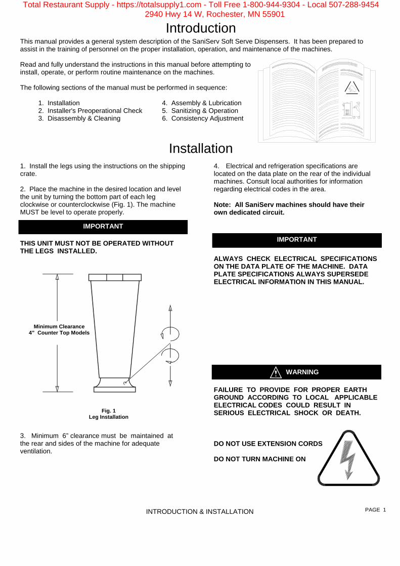
1. Install the legs using the instructions on the shipping crate. 2. Place the machine in the desired location and level the unit by turning the bottom part of each leg clockwise or counterclockwise (Fig. 1). The machine MUST be level to operate properly.
THIS UNIT MUST NOT BE OPERATED WITHOUT THE LEGS INSTALLED.
3. Minimum 6” clearance must be maintained at the rear and sides of the machine for adequate ventilation.
4. Electrical and refrigeration specifications are located on the data plate on the rear of the individual machines. Consult local authorities for information regarding electrical codes in the area. Note: All SaniServ machines should have their own dedicated circuit.
ALWAYS CHECK ELECTRICAL SPECIFlCATIONS ON THE DATA PLATE OF THE MACHINE. DATA PLATE SPECIFICATIONS ALWAYS SUPERSEDE ELECTRICAL INFORMATION IN THIS MANUAL.
FAILURE TO PROVIDE FOR PROPER EARTH GROUND ACCORDING TO LOCAL APPLICABLE ELECTRICAL CODES COULD RESULT IN SERIOUS ELECTRICAL SHOCK OR DEATH. DO NOT USE EXTENSION CORDS DO NOT TURN MACHINE ON
Introduction
Installation
Fig. 1 Leg Installation
Minimum Clearance 4” Counter Top Models
WARNING
IMPORTANT
This manual provides a general system description of the SaniServ Soft Serve Dispensers. It has been prepared to assist in the training of personnel on the proper installation, operation, and maintenance of the machines. Read and fully understand the instructions in this manual before attempting to install, operate, or perform routine maintenance on the machines. The following sections of the manual must be performed in sequence: 1. Installation 4. Assembly & Lubrication 2. Installer's Preoperational Check 5. Sanitizing & Operation 3. Disassembly & Cleaning 6. Consistency Adjustment
PAGE 1
IMPORTANT
Total Restaurant Supply - https://totalsupply1.com - Toll Free 1-800-944-9304 - Local 507-288-94542940 Hwy 14 W, Rochester, MN 55901

Emptying Machine Prior to the disassembly and cleaning of parts, the machine must be emptied of product. Use the following procedures (Steps 1 through 3). If this is first time operation, disregard these steps.
DO NOT INSERT ANY OBJECTS OR TOOLS INTO THE MIX INLET HOLE, CARBURETOR TUBE HOLE, OR FRONT PLATE DISPENSING HOLE WHILE THE MACHINE IS RUNNING. DAMAGE TO THE MACHINE OR PERSONAL INJURY MAY RESULT. 1. Remove the carburetor tube (Fig. 3) from the mix inlet hole and lay in the bottom of the mix pan. 2. Set the control switch (Fig. 2) to the “CLEANOUT” position and dispense all product from the freezing cylinder by pulling downward on the spigot handle (Fig. 4) to empty the machine. 3. Set the control switch to the “OFF” (center) position. Close the spigot handle before proceeding to cleaning.
Disassembly and Cleaning Procedure 1. Fill the machine with cold water and set the control switch to the “CLEANOUT” position. DO NOT use hot water which could damage the machine. Let the machine agitate briefly and drain the water by pulling downward on the spigot handle. After the machine is empty, set the control switch to the “OFF” position. Repeat the above procedure as necessary to make certain that all product is removed from the machine. 2. Prepare a suitable detergent and water solution at a temperature of 125° to 130° F. DO NOT use an abrasive detergent on any part of the dispenser.
DO NOT USE HOT WATER DOING SO COULD DAMAGE YOUR MACHINE
3. Fill the mix pan with the cleaning solution. Make certain that the machine is “OFF”. Clean the mix pan thoroughly with a brush as the solution drains into the freezing cylinder. Clean the mix inlet tube and the carburetor tube holes with the brush provided.
Disassembly & Cleaning
CONSULT YOUR LOCAL HEALTH AGENCY FOR CLEANING AND SANITIZING REQUIREMENTS. This unit does not come presanitized from the factory. Before serving product, the dispenser must be disassembled, cleaned, lubricated, and sanitized. These instructions are general guidelines only. Cleaning and sanitizing procedures must conform to local health agency requirements.
WARNING
DISASSEMBLY & CLEANING
Fig. 4 Dispensing Product
PAGE 2
IMPORTANT
O-Ring
Fig. 3 Carburetor Tube
Fig. 2 Control Switch
Total Restaurant Supply - https://totalsupply1.com - Toll Free 1-800-944-9304 - Local 507-288-94542940 Hwy 14 W, Rochester, MN 55901

4. Set the control switch to the “CLEANOUT” position and agitate for approximately 1 - 2 minutes and then drain the water by opening the spigot. After the unit is empty, set the control switch to the “OFF” position. 5. Remove the front plate by turning the black plastic knobs in a counterclockwise direction (Fig. 5). Disassemble the front plate in the following manner:
DO NOT USE ANY TOOLS OR SHARP OBJECTS TO REMOVE ANY O-RINGS FROM THIS MACHINE. SHARP OBJECTS WILL DAMAGE THE O-RINGS. a. Remove the faspin and spigot handle. b. Remove the front plate o-ring. c. With the spigot handle removed, push the spigot plunger out the top of the front plate. d. Remove the o-rings from the spigot plunger by grasping the part with one hand and with a dry cloth in the other hand, squeeze the o-ring upward. When a loop is formed, grasp the o-ring with the other hand and roll it out of its groove and off the part (Fig. 6).
6. Remove the carburetor tube (Fig. 7) from the mix pan. Disassemble and clean in the following manner: a. Remove the o-ring from the bottom of the tube. b. Clean the inside of the tube with the brush.
7. Remove the dasher assembly (Fig. 8) being careful not to damage the scraper blades, then disassemble in the following manner: a. Remove and take apart the rear seal assembly. b. Remove the stator rod from the dasher. C. Remove the blade from the dasher (Fig. 9a) by first rotating blade upward (Fig. 9b) and then unsnapping one end from the support rod.
BLADES MUST BE REMOVED FOR CLEANING.
IMPORTANT
DISASSEMBLY & CLEANING
Fig. 5 Face Plate Assembly
Spigot Plunger
Faspin
Spigot Handle
Front Plate
Front Plate O-ring DO NOT LUBRICATE
Spigot Plunger O-rings
Front Plate Knobs
Fig. 6 O-Ring Removal
Fig. 7 Carburetor Tube
PAGE 3
O-ring
Mix Inlet Hole
Total Restaurant Supply - https://totalsupply1.com - Toll Free 1-800-944-9304 - Local 507-288-94542940 Hwy 14 W, Rochester, MN 55901

9. Remove the mix pan lid, mix pan agitator, drip tray and drip tray insert. Place all parts in a three partition sink filled with the following solutions: a. In one partition, mild detergent solution. b. In a second partition, clear rinse. c. In a third partition, sanitizing rinse consisting of 200 parts per million (PPM) chlorine residual.
Fig. 11
Drip Tray Assembly
10. Use the small diameter brush to clean all holes and ports in the parts. DO NOT use an abrasive detergent. 11. After thoroughly washing the parts in the detergent solution, rinse them in the rinse water. Place the parts in the sanitizing solution for five (5) minutes and then air dry to prepare for assembly and lubrication. DO NOT wipe dry. 12. The remainder of the machine including the mix pan and freezing cylinder must be cleaned in place using a mild detergent solution. Clean the exterior with a damp cloth. DO NOT use an abrasive cleaner on exterior panels.
WHEN CLEANING THE MACHINE, DO NOT ALLOW EXCESSIVE AMOUNTS OF WATER AROUND ANY ELECTRICALLY OPERATED COMPONENTS OF THE MACHINE. ELECTRICAL SHOCK OR DAMAGE TO THE MACHINE MAY RESULT.
Dasher Front View Scraper Blade
Blade Support Tab
Support Rod
Blade Support Tab
Support Rod
Dasher Front View
Scraper Blade
WARNING
DISASSEMBLY & CLEANING
Drip Tray Insert
Drip Tray
Drip Tray Support Remains Attached to Machine
ELECTRICAL SHOCK HAZARD
Fig. 9a Scraper Blade Removal
Fig. 9b Scraper Blade Removal
PAGE 4
Total Restaurant Supply - https://totalsupply1.com - Toll Free 1-800-944-9304 - Local 507-288-94542940 Hwy 14 W, Rochester, MN 55901

1. Lubricate and assemble the dasher assembly in the following manner: a. Apply a generous amount of lubricant to the shoulder of the dasher and the area of the shaft where the white plastic portion of the assembled rear seal contacts the shaft (Fig. 12). This is easily performed by running a 1/4” bead of lubricant around the shoulder of the dasher. b. Lubricate the stator rod (Fig. 12) and slide the stator rod into the dasher. C. Assemble and install the rear bearing and seal with the rubber portion toward the rear of the freezing cylinder as indicated in Fig. 13.
d. Install the scraper blades on the dasher assembly by holding the blade perpendicular to the tabs (Fig. 14a) and then snapping them over the flat area of the support rod. Then rotate the blade downward in a counterclockwise direction as viewed from the front of the dasher (Fig. 14b). Note: Reverse the blades at each cleaning to maintain sharpness. In addition, the blades are equipped with a wear mark (Fig. 14c). When the blade is worn to this wear mark, they must be replaced.
Assembly & Lubrication
Use only food approved lubricants. Sanigel (SaniServ part number 188490) is recommended and is available from your local authorized SaniServ dealer or distributor. Lubrication must be performed daily.
Blade Support Tab
Support Rod
Dasher Front View Scraper Blade
Dasher Front View
Blade Support Tab Support Rod
Scraper Blade
Rotate Down Counter Clockwise
Scraper Blade Wear Mark
End View
Side View
ASSEMBLY & LUBRICATION PAGE 5
Fig. 14c Scraper Blade Wear Mark
Fig. 14a Scraper Blade Installation
Fig. 14b Scraper Blade Installation
Fig. 12 Stator Rod and Dasher Lubrication
CAUTION
Fig. 13 Dasher Assembly
DO NOT LUBRICATE THE BACK SIDE OF THE RUBBER PORTION OF THE SEAL ASSEMBLY. MACHINE COULD BE DAMAGED.
Lubricate Shaded Areas
Total Restaurant Supply - https://totalsupply1.com - Toll Free 1-800-944-9304 - Local 507-288-94542940 Hwy 14 W, Rochester, MN 55901
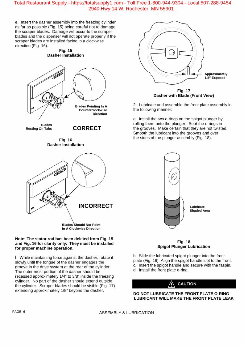
e. Insert the dasher assembly into the freezing cylinder as far as possible (Fig. 15) being careful not to damage the scraper blades. Damage will occur to the scraper blades and the dispenser will not operate properly if the scraper blades are installed facing in a clockwise direction (Fig. 16).
Fig. 15 Dasher Installation
Fig. 16
Dasher Installation
Note: The stator rod has been deleted from Fig. 15 and Fig. 16 for clarity only. They must be installed for proper machine operation. f. While maintaining force against the dasher, rotate it slowly until the tongue of the dasher engages the groove in the drive system at the rear of the cylinder. The outer most portion of the dasher should be recessed approximately 1/4” to 3/8” inside the freezing cylinder. No part of the dasher should extend outside the cylinder. Scraper blades should be visible (Fig. 17) extending approximately 1/8” beyond the dasher.
CORRECT
Fig. 17 Dasher with Blade (Front View)
2. Lubricate and assemble the front plate assembly in the following manner: a. Install the two o-rings on the spigot plunger by rolling them onto the plunger. Seat the o-rings in the grooves. Make certain that they are not twisted. Smooth the lubricant into the grooves and over the sides of the plunger assembly (Fig. 18).
Fig. 18
Spigot Plunger Lubrication b. Slide the lubricated spigot plunger into the front plate (Fig. 19) Align the spigot handle slot to the front. c. Insert the spigot handle and secure with the faspin. d. Install the front plate o-ring.
DO NOT LUBRICATE THE FRONT PLATE O-RING LUBRICANT WILL MAKE THE FRONT PLATE LEAK
ASSEMBLY & LUBRICATION
Lubricate Shaded Area
Approximately 1/8” Exposed
Blades Should Not Point In A Clockwise Direction
INCORRECT
PAGE 6
CAUTION
Blades Resting On Tabs
Blades Pointing In A Counterclockwise
Direction
Total Restaurant Supply - https://totalsupply1.com - Toll Free 1-800-944-9304 - Local 507-288-94542940 Hwy 14 W, Rochester, MN 55901

Fig. 19
Front Plate Assembly
e. Align the front plate to the freezing cylinder, place the square pocket on the back side of the front plate over the end of the stator rod, and secure the front plate assembly to the machine with the two plastic knobs. Turn both of the knobs in a clockwise direction simultaneously. Tighten the knobs evenly. DO NOT tighten one knob all the way down and then the other. Doing so may result in front plate breakage. Only moderate force is required. DO NOT over tighten. Set the spigot plunger to the closed position. 4. Install the o-ring on the carburetor assembly (Fig. 22). Apply lubricant sparingly over the o-ring. Place the assembled carburetor tube in the bottom of the mix pan for sanitizing. Lubricant MUST NOT BLOCK the mix inlet hole on the carburetor tube.
ASSEMBLY & LUBRICATION
Spigot Plunger
Faspin
Spigot Handle
Front Plate
Front Plate O-ring DO NOT LUBRICATE
Spigot Plunger O-rings
Front Plate Knobs
PAGE 7
O-ring
Mix Inlet Hole
Fig. 22 Carburetor Tube Assembly
Carburetor Tube
Carburetor Tube O-ring
Fig. 23 Mix Pan
Components
Drip Tray Insert
Drip Tray Drip Tray Support Remains Attached to Machine
Fig. 24 Drip Tray Assembly
Total Restaurant Supply - https://totalsupply1.com - Toll Free 1-800-944-9304 - Local 507-288-94542940 Hwy 14 W, Rochester, MN 55901
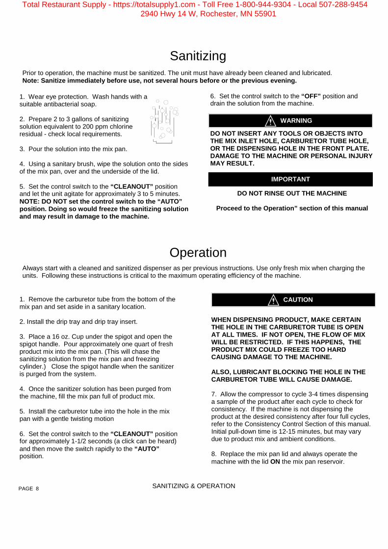
1. Wear eye protection. Wash hands with a suitable antibacterial soap. 2. Prepare 2 to 3 gallons of sanitizing solution equivalent to 200 ppm chlorine residual - check local requirements. 3. Pour the solution into the mix pan. 4. Using a sanitary brush, wipe the solution onto the sides of the mix pan, over and the underside of the lid. 5. Set the control switch to the “CLEANOUT” position and let the unit agitate for approximately 3 to 5 minutes. NOTE: DO NOT set the control switch to the “AUTO” position. Doing so would freeze the sanitizing solution and may result in damage to the machine.
6. Set the control switch to the “OFF” position and drain the solution from the machine.
DO NOT INSERT ANY TOOLS OR OBJECTS INTO THE MIX INLET HOLE, CARBURETOR TUBE HOLE, OR THE DISPENSING HOLE IN THE FRONT PLATE. DAMAGE TO THE MACHINE OR PERSONAL INJURY MAY RESULT.
DO NOT RINSE OUT THE MACHINE
Proceed to the Operation” section of this manual
Sanitizing
Prior to operation, the machine must be sanitized. The unit must have already been cleaned and lubricated. Note: Sanitize immediately before use, not several hours before or the previous evening.
WARNING
IMPORTANT
Operation
Always start with a cleaned and sanitized dispenser as per previous instructions. Use only fresh mix when charging the units. Following these instructions is critical to the maximum operating efficiency of the machine.
1. Remove the carburetor tube from the bottom of the mix pan and set aside in a sanitary location. 2. Install the drip tray and drip tray insert. 3. Place a 16 oz. Cup under the spigot and open the spigot handle. Pour approximately one quart of fresh product mix into the mix pan. (This will chase the sanitizing solution from the mix pan and freezing cylinder.) Close the spigot handle when the sanitizer is purged from the system. 4. Once the sanitizer solution has been purged from the machine, fill the mix pan full of product mix. 5. Install the carburetor tube into the hole in the mix pan with a gentle twisting motion 6. Set the control switch to the “CLEANOUT” position for approximately 1-1/2 seconds (a click can be heard) and then move the switch rapidly to the “AUTO” position.
SANITIZING & OPERATION PAGE 8
WHEN DISPENSING PRODUCT, MAKE CERTAIN THE HOLE IN THE CARBURETOR TUBE IS OPEN AT ALL TIMES. IF NOT OPEN, THE FLOW OF MIX WILL BE RESTRICTED. IF THIS HAPPENS, THE PRODUCT MIX COULD FREEZE TOO HARD CAUSING DAMAGE TO THE MACHINE. ALSO, LUBRICANT BLOCKING THE HOLE IN THE CARBURETOR TUBE WILL CAUSE DAMAGE. 7. Allow the compressor to cycle 3-4 times dispensing a sample of the product after each cycle to check for consistency. If the machine is not dispensing the product at the desired consistency after four full cycles, refer to the Consistency Control Section of this manual. Initial pull-down time is 12-15 minutes, but may vary due to product mix and ambient conditions. 8. Replace the mix pan lid and always operate the machine with the lid ON the mix pan reservoir.
CAUTION
Total Restaurant Supply - https://totalsupply1.com - Toll Free 1-800-944-9304 - Local 507-288-94542940 Hwy 14 W, Rochester, MN 55901
Helpful Hints
HELPFUL HINTS PAGE 9
Front Plate: This component is the plastic device from which the product is dispensed. It is designed and manufactured for strength and durability. However, through improper use, the front plate can be damaged. Use the following information for proper care: a. Do not over tighten the knobs. b. Always tighten knobs evenly. Do not attempt to turn one knob all the way down and then one of the other three knobs. Doing so will bind the front plate and could result in breakage. c. Improper installation of the stator rods can cause breakage. The stator rods must be properly seated in the dasher before installing the front plate. If the stator rods are improperly installed, subsequent tightening of the knobs will break the front plate. d. DO NOT attempt to wash the front plate or any other components in a dishwasher. Filling: Always fill the machine with fresh product at the start of each day. Drip Tray: This should be removed daily and cleaned to remove residue. Mix Pan Lid: Be certain to leave the lid in place on top of the machine to prevent any foreign materials from contaminating the mix. Mixing: Make certain that the product mix is prepared according to label instructions. Sanitizing: Do not soak plastic parts in sanitizer overnight. Doing so can cause the plastic parts to become brittle and lead to premature failure.
Winter Storage: To protect the unit during seasonal shut-down, it is important that the dispenser be stored in the proper manner. Use the following procedures: 1. Turn off ALL power to the machine. 2. Wash all parts that come in contact with the mix
with a warm mild detergent solution. Rinse in clear water and dry parts thoroughly.
3. Store the loose parts such as the mix pan components, front plate parts, and the dasher assembly parts outside of the machine.
4. Do not lay heavy objects on the plastic or rubber parts.
5. Cover the machine and all loose parts to protect them from dust or other contaminants while in storage. Place the machine in a dry location.
Total Restaurant Supply - https://totalsupply1.com - Toll Free 1-800-944-9304 - Local 507-288-94542940 Hwy 14 W, Rochester, MN 55901

Consistency Control System Adjustments to the consistency control should only be made by a serviceman trained on SaniServ equipment . DO NOT attempt to make repairs on the machine. The mechanical control system is a very simple method of controlling the consistency of the finished product. The machine operates without a temperature control. Refrigeration is controlled by measuring the torque on the dasher motor and the consistency of the product. The tension of a spring against the torque idler determines how long the unit will run by activating a limit switch which turns the compressor on and off. The longer the compressor runs, the harder the product. The less it runs, the softer the product. This directly relates to product temperature. Initial adjustments have been performed at the factory. However, to satisfy individual preferences, the following adjustments may be required: 1. Remove the right side panel as viewed from the front of the machine. 2. Using a regular straight screwdriver, turn the mechanical consistency or torque adjustment screw (Fig. 28) clockwise to make the product harder and counterclockwise to make the product softer. Do not adjust more than two turns each time. Do not attempt to adjust the belt idler screw on the left side of the machine marked “Do Not Adjust”. EXTREME CARE SHOULD BE EXERCISED TO KEEP HANDS AND TOOLS AWAY FROM MOVING
PARTS. PERSONAL INJURY COULD RESULT. 3. Replace panels, restore power, wait until the compressor cycles off, then check the consistency of the product. 4. Repeat steps 2 and 3 until the desired product consistency is obtained.
Consistency Adjustment
CAUTION: The following procedure should ONLY be performed by a trained Technician.
NOTE: If product does not freeze to a hard enough consistency, the problem may not be in the machine. To verify, use a standard thermometer to obtain the temperature of the product. The problem is NOT in the machine if the temperature is between 17° and 22° F. Check to see that the product mix was prepared to the manufacturer’s recommendation.
WARNING
5. Install the right side panel, and the machine is ready for continuous operation.
CONSISTENCY ADJUSTMENT
SEVERE ELECTRICAL
SHOCK HAZARD
HAND PINCH OR ENTRAPMENT
HAZARD
PAGE 10
WARNING
USE EXTREME CAUTION. ELECTRICAL SHOCK HAZARD EXISTS EVEN WHEN THE UNIT IS IN THE “OFF” POSITION. DISCONNECT THE MACHINE FROM ALL OF ITS POWER SOURCES BEFORE PERFORMING ADJUSTMENTS ON THE MACHINE. PERSONAL INJURY OR DAMAGE TO THE MACHINE COULD RESULT IF THIS PRECAUTION IS NOT OBSERVED. ALL PANELS SHOULD BE REPLACED AND ALL POWER SOURCES SHOULD BE RESTORED BETWEEN EACH CONSISTENCY ADJUSTMENT.
Fig. 28 Mechanical
Consistency Control
Rotation
Torque Adjustment
TORQUE IDLER
BELT IDLER
Total Restaurant Supply - https://totalsupply1.com - Toll Free 1-800-944-9304 - Local 507-288-94542940 Hwy 14 W, Rochester, MN 55901

Routine Maintenance (Trained Service Technician)
Routine Maintenance (Owner-Operator)
ROUTINE MAINTENANCE
Scraper Blade Wear Mark
End View
Side View
Fig. 30 Scraper Blade Wear Mark
CONDENSER FINS ARE VERY SHARP USE EXTREME CAUTION WHEN CLEANING
Quarterly: Thoroughly clean the condenser fins on all air-cooled machines. Remove all lint and dust with a vacuum cleaner or compressed air (Fig. 32) to clean fins. A dirty condenser greatly reduces refrigeration capacity and efficiency. When using compressed air, place a damp cloth on the opposite side of the condenser to catch the flying dirt or lint. Annually: Check the belts for signs of wear or cracking. Remove panels and clean all parts inside of the machine including the base, side panels, fan blades, condensers, etc.
Fig. 31 Drip Chute
DISCONNECT THE MACHINE FROM ITS POWER SOURCE(S) BEFORE PERFORMING ANY ROUTINE MAINTENANCE. PERSONAL INJURY OR DAMAGE TO THE MACHINE COULD RESULT IF THIS PRACTICE IS NOT OBSERVED. Daily: Inspect the machine for signs of product leaks past seals and gaskets. If proper assembly does not stop leaks around gaskets or seals, check for improper lubrication and worn or damaged parts. Replace parts as needed. Periodically: Inspect the scraper blades (Fig. 30) to see that they are straight and sharp. If worn, damaged or warped, the blades will not scrape the cylinder walls correctly and the freezing capacity will be reduced. Clean the drip chute assembly (Fig. 31) with warm water and detergent solution.
Fig. 32 Clean Sharp Condenser Fins
WARNING
WARNING
PAGE 11
Total Restaurant Supply - https://totalsupply1.com - Toll Free 1-800-944-9304 - Local 507-288-94542940 Hwy 14 W, Rochester, MN 55901

ROUTINE MAINTENANCE
HAZARDOUS MOVING PARTS Semiannually: It is advisable to clean and lubricate the idler arms (Fig. 33) to ensure their smooth operation. Use the following procedures: 1. Make certain that ALL power to the dispenser is off. 2. Remove both side panels first, then remove the rear panel of the machine. 3. Use a pencil to mark the position of the nut (Fig 33) on the side of the belt idler arm spring adjustment mechanism. Relieve the tension on the spring by turning the adjustment screw near the label which warns: DO NOT ADJUST. Disconnect the spring from the belt idler arm by placing needle nose pliers on one end of the spring and pulling the end out of the retainer. 4. Remove the nut and idler arm from the pivot point of the belt idler arm assembly. 5. Remove the belt idler arm and inspect the pivot point. These areas should be free of rust, debris, or dried lubricant. If any of these substances are found, they must be removed. 6. Clean and polish the sleeve surface with a fine grade of emery cloth and apply anti-seize compound. 7. Reinstall the belt idler arm.
DO NOT OVERTIGHTEN THE LOCKING NUT. ON SOME UNITS IT IS POSSIBLE TO OVERTIGHTEN THE LOCKING NUT AND CAUSE THE IDLER ARMS TO BIND. THE ARMS SHOULD MOVE FREELY. 8. Repeat the process for the torque idler arm. 9. Install the belt making certain that there is no grease on the belt or pulleys. Step to the side of the unit and view the belt to determine whether or not it is properly aligned (straight from top to bottom). 10. Reinstall the torque idler arm spring and the belt idler arm spring and turn the adjustment screws returning the adjustment nuts to the pencil marks you placed on the side of each adjustment mechanism in step 3 above.
Fig. 33 Torque Spring Adjustment Mechanism
Routine Maintenance (Trained Service Technician)
WARNING
11. Check the product for proper consistency and adjust as required. When the consistency is right, replace the rear and both side panels.
CAUTION
PAGE 12
Rotation
Torque Adjustment
TORQUE IDLER
BELT IDLER
Torque Idler Arm Pivot
Mark Nut Position on Housing With Pencil
Mark Nut Position on
Housing With Pencil
Belt Idler Arm Pivot
Total Restaurant Supply - https://totalsupply1.com - Toll Free 1-800-944-9304 - Local 507-288-94542940 Hwy 14 W, Rochester, MN 55901

PAGE 13 TROUBLESHOOTING GUIDE
Please make these simple checks prior to contacting you service provider. Because adjustments to the machine are not coveredunder the terms of warranty, these tips can save you time and money. If you feel you are not comfortable performing trouble-shootingsuggestions, please contact your local certified service provider.
Machine will not start
Make sure electrical cord is correctly seated in the electrical receptacle. Check circuit breaker in electrical panel.
Product is Soft
Do not make a consistency adjustment at this point. Always check product temperature first. Should be between 18-21 degrees soft serve, 17-20 degree’s yogurt. If temperature is lower than listed, product is broken down. See Product Breakdown in glossary section. Replace with fresh product.
Check for properly mixed product. Replace as necessary If using Re-run product, remove product and add fresh mix. Confirm that the carbtube has been installed. Product will not thicken without carbtube. Check for dull scraper blades. Blades should be sharp. Replace every 6 months. Check Condenser for dirt or obstructions. See Quarterly Maintenance Confirm that the condenser fan is running. Confirm 6” of airflow on all both sides and back of machine. High ambient temperature. Recommended machine ambient temperature not to exceed 82 degrees.
Product is too Thick
Check for properly mixed product. Confirm freezing cylinder is not starved of product. See glossary (Starved Cylinder) Check product temperature. Should be between 18-21 degrees soft serve, 17-20 degree’s yogurt. Check for missing scraper blade or stator rod. Check dasher assemblies. Check for sticking spigot lever and or switch. If stuck in the up position, will cause unit to run continually.
Front Plate Leaking
Confirm front plate o-ring is not ripped or torn. Replace if necessary. Replace seals and o-rings every six months.
Do not lubricate front plate o-ring. Confirm spigot plunger o-rings are not ripped or torn. Replace if necessary. Replace every six months. Confirm spigot plunger o-rings are lubricated daily. Tighten front plate knobs evenly. Confirm stator rod is not worn or grooved.
Product leaking from the drip chute and or drip tube.
Rear Seal is worn. Replace. Note: Replace seals, o-rings and gaskets every six months. Do Not Lubricate the rubber portion of the rear seal The shaft of the dasher where the rear seal is installed must be lubricated daily. Confirm stator rod is not worn or grooved. Front plate knobs loose.
Squeaking , chirping noises and or vibration heard.
Use properly mixed product. Replace as necessary. Confirm freezing cylinder is not starved of product. See glossary (Starved Cylinder) Check lubrication Confirm all panel screws are installed and tightened Adjust width of drip tray bracket. Check for dull scraper blades. Blades should be sharp. Replace every 6 months.
Product in mix-pan too warm.
Refrigerate product prior to use. Confirm storage source of product at 40 degrees or below. Maintain product level of ½ to ¾ full in mix-pan reservoir. Mix-pan lid must be installed at all times to prevent foreign materials contaminating product and to insulate
product in the mix-pan . Who to contact for service and parts
If you do not have a local service and parts provider, contact your SaniServ Dealer/Distributor. Visit www.saniserv.com to locate a Distributor (Sales Section) or a Service Agent (Technical Support Section).
Troubleshooting
Total Restaurant Supply - https://totalsupply1.com - Toll Free 1-800-944-9304 - Local 507-288-94542940 Hwy 14 W, Rochester, MN 55901

PAGE 14 TROUBLESHOOTING GLOSSARY
Trouble Shooting Glossary Ambient Temperature. The temperature of the air in the immediate vicinity of the operating machine. High ambi-ent temperature can reduce the capacity with an air-cooled condenser. Carbtube. Flow control device that allows product and air to be blended together. The air added to the product is labeled as over-run. The over-run helps provide a thick and rich product. If the carbtube is not used the product will be heavy, wet, grainy, will not thicken and product temperatures will be lower than the specified 18-21 degrees soft serve. Condenser. The part of the refrigeration mechanism that receives hot, high-pressure refrigeration gas from the compressor and cools gaseous refrigerant until it returns to a liquid state. Consistency. The viscosity or thickness of the product in the freezing cylinder. Consistency Control. A control that senses the thickness or viscosity of the product in the freezing cylinder. Dasher. The part of the freezer that scrapes frozen product off the inside of the freezing cylinder and blends the product. In a gravity freezer, this assembly also moves the product forward to be dispensed. Front Plate. Seals the front of the freezing cylinder and provides a means for dispensing the product. On gravity fed freezers, the front plate indirectly holds the dasher in place via the stator rod. It also provides compression for the rear seal. Freezing Cylinder. The part of the refrigeration mechanism in which the refrigerant vaporizes and absorbs heat. This is the part of the freezer where the liquid product is frozen. Mix-pan. Is the top container that product is poured into. It is used as storage until product is needed for the freezing cylinder. Mixing Product / Product Temperatures. If your using a product that has to be mixed with water or other ingredi-ents, it is imperative the product is mixed consistently everyday. If not, the machine will not run consistent and could possibly damage components. Always mix to the product manufactures recommendations. The machine is designed to operate with a frozen product that falls within these temperatures (soft serve 18-21 degrees, yogurt 17-20 degrees). Overrun. The volumetric increase of product from the liquid to the solid state due to the incorporation of air into the frozen product. Overrun is states as a percentage. Product Breakdown. The decline in frozen product quality resulting from excess agitation or temperature varia-tions of product that has been in the freezing cylinder too long. Product, which has broken down, may be grainy, wet and or heavy. Product breakdown is easily detected by taking the temperature of the dispensed product. Temperatures will always be lower than recommended product temperatures.
Total Restaurant Supply - https://totalsupply1.com - Toll Free 1-800-944-9304 - Local 507-288-94542940 Hwy 14 W, Rochester, MN 55901

PAGE 15 TROUBLESHOOTING GLOSSARY
Trouble Shooting Glossary Rear Seal. This part is stationary during operation and must not move. When installed and lubed properly, seals mix in cylinder. When installed and lubed improperly, it causes main shafted bearing failure. Rerun. The reuse of previously frozen product after it has melted to a liquid. Rerun is obtained when emptying a freezer for periodic cleaning. Use caution when using rerun as it may contain high bacteria or Coli count, which could contaminate the fresh mix with which it is combined. Freezers should never be started with rerun. If used at all, it should be blended with fresh mix at a ratio of seven parts new mix with three parts old mix, after initial freeze-down with fresh mix. Scraper Blades. The component that scrapes the frozen product from the freezing cylinder surface. Blades must be sharp, as dull blades will leave product on the freezing cylinder, insulating the mix from the refrigerant. Spigot Plunger. The mechanism on the front plate through which the product is dispensed. Starved Cylinder. A starved cylinder is often mistaken for a freeze up or product too thick. A starved cylinder (starving) is created when a larger percentage of frozen product is dispensed from the freezing cylinder than the percentage of liquid product entering the freezing cylinder from the mix-pan. There are several causes of starving. 1. Overdrawing: Dispensing more product from the machine than it’s designed to do. This would occur if a ma-
chine were undersized for its application. 2. Inserting the carbtube prior to pouring the initial product into the mix-pan at the start of each day. This forms a
vacuum and traps a large percentage of air in the cylinder; therefore the cylinder will not fill with product. 3. Carbtube not being cleaned, thus allowing product build-up in the carbtube holes. This restricts product from
entering the freezing cylinder. 4. Pouring frozen or semi frozen product into the mix-pan reservoir. This will form a blockage in the carbtube
hole and not allow liquid product to flow into the cylinder. 5. Mix-pan too cold, allowing product to freeze in mix-pan and restricting product flow. Stator Rod. Acts as a bearing surface. Helps enfold air for overrun. Transmits compression to the rear seal. Helps mechanical torque system sense torque. Be sure to lubricate.
Total Restaurant Supply - https://totalsupply1.com - Toll Free 1-800-944-9304 - Local 507-288-94542940 Hwy 14 W, Rochester, MN 55901
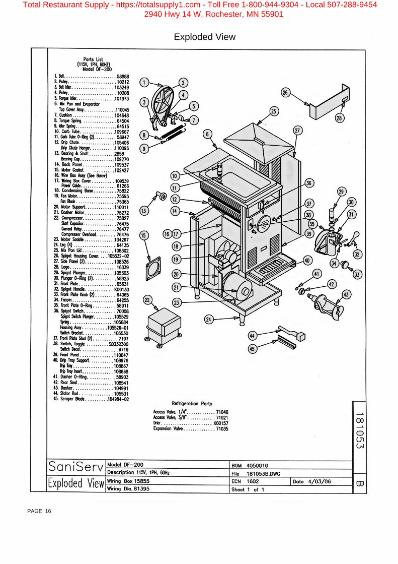
Exploded View
PAGE 16
Total Restaurant Supply - https://totalsupply1.com - Toll Free 1-800-944-9304 - Local 507-288-94542940 Hwy 14 W, Rochester, MN 55901

Wiring Diagram
PAGE 17
Total Restaurant Supply - https://totalsupply1.com - Toll Free 1-800-944-9304 - Local 507-288-94542940 Hwy 14 W, Rochester, MN 55901

Date Service Performed Serviceman’s Signature
Service Record
SERVICE RECORD
Total Restaurant Supply - https://totalsupply1.com - Toll Free 1-800-944-9304 - Local 507-288-94542940 Hwy 14 W, Rochester, MN 55901

This Page Intentionally Blank
Total Restaurant Supply - https://totalsupply1.com - Toll Free 1-800-944-9304 - Local 507-288-94542940 Hwy 14 W, Rochester, MN 55901

Proudly made in the U.S.A.
Technical Publication Publ. No. 80856
Updated 4/06
451 E. County Line Road P.O. Box 1089
Mooresville, Indiana 46158-5089
SaniServ® An AFFINIS GROUP Company
We are on the web... www.saniserv.com
Total Restaurant Supply - https://totalsupply1.com - Toll Free 1-800-944-9304 - Local 507-288-94542940 Hwy 14 W, Rochester, MN 55901