manual cambo artes ept cambo artes ept.pdf · please read this manual carefully before using the...
TRANSCRIPT

ARTES-EPT
VIDEO-BOOM / MOTORISED PAN AND TILT UNIT
USER MANUAL EN
Please read this manual carefully before using the Cambo ARTES ETP unit!
CAMBO

ARTES EPT USER MANUAL
CAMBO©
| MADE IN THE NETHERLAND 2
Thank you for purchasing a Cambo® product
The EPT head is developed for the lightweight range of Video Booms. The motor-driven controls allows for
over 360 degrees rotation of unobstructed pan and tilt. Durable motors assure for a long and reliable life.
The head unit is connected with a standard UTP cable up to 10 meter to the control unit.
Please note: the manual is divided into two parts. The first part is the
instruction for the EPT-unit and the second part is the
instruction for the ARTES-unit.
The ARTES/EPT unit includes:
• ARTES video boom
• EPT adapter stud
• Head Unit with Camera Platform
• Remote Control Joystick including handle and clamp unit
• Control frame including clamp unit
• AC/DC power adapter 110-240 V
• Signal/power cable 5meter length CAT-6 UTP cable
WARNING
WARNING: rotating gears - finger or hand entanglement
Please keep hands and fingers clear from the operational gear units.
WARNING: moving parts - finger or hand crush
Please keep hands and fingers clear from the moving parts of the operational EPT
unit.
WARNING: twisting of the cables
Never rotate the pan or tilt movement more than two times around the axis
(720degrees).
Before use check if the cables are twisted. Always untwist the cables before using
the EPT unit. To untwist the cables at the pan and tilt axis by rotating the head in
the opposite direction of the twisted cable.
WARNING: keep clear of obstacles when operating the EPT head.
CAUTION: do not manually force the pan or tilt movement when the gears are
coupled, this may irreversibly damage the gears.
CAUTION: do not over-tighten knobs (5) and (6) shown in figure 1
INSTRUCTION EPT-UNIT

ARTES EPT USER MANUAL
CAMBO©
| MADE IN THE NETHERLAND 3
figure 1: EPT head

ARTES EPT USER MANUAL
CAMBO©
| MADE IN THE NETHERLAND 4
figure 2: EPT remote
Please note: these numbers only correspond to images 9 to 15.
1 Cambo video-boom mount 16 Cable output EPT topside
2 Mount hole attachment handle 17 Cable feed-through to the camera
3 Tripod mount (3/8”) 18 Cable connector for the joystick unit
4 Motor unit pan-movement 19 Direction switch tilt movement
5 Locking knob motor slider (top) 20 Direction switch pan movement
6 Locking knob motor slider (side) 21 Power-on led motor control unit
7 Brass motor gear (M0.5 z=42) 22 Cambo control frame mount
8 Delrin gear (M0.5 z=140) 23 Clamp joystick handle
9 Motor unit tilt-movement 24 Joystick unit
10 Motor control unit 25 Power switch EPT
11 Cable feed-through EPT topside 26 Power-on led joystick unit
12 Cable output camera side 27 Joystick pan/tilt movement, speed switch
13 Camera plate 28 Led indicator high speed setting
14 Camera screw (3/8” and 1/4") 29 Led indicator low speed setting
15 Camera height adjustment screw (Hex key 5mm)
Mounting the EPT unit to the ARTES

ARTES EPT USER MANUAL
CAMBO©
| MADE IN THE NETHERLAND 5
figure 3: EPT mount
The image above shows the EPT unit mounted to the ARTES.
Mounting the EPT unit to a tripod
The EPT can also be mounted upside-down to a tripod using the tripod mount (20). When the EPT is used
upside down the directions are mirrored, you can use the switches (19) and (20) to change the direction as
desired.

ARTES EPT USER MANUAL
CAMBO©
| MADE IN THE NETHERLAND 6
figure 4: decouple the gears
Mounting and balancing the camera
Camera's up to 5 kg can be used with the EPT
head. It is advised to use a sliding quick release
plate for mounting the camera to the EPT head.
It is important that the camera is balanced
correctly for an optimal pan and tilt movement.
The camera is balanced correctly when the centre
of mass of the camera, lens, adapter plate and
camera plate (13 fig.1) is in the axis of the tilt
movement.
To balance the camera:
1. decouple the gears by loosening the two
knobs (5) and (6)
2. slide the motor unit (9) upwards
3. when the gears are decoupled please lock
either knob (5) or (6)
4. now the tilt movement can swivel freely
around its axis, move the camera to the
front or back until the camera is stationary
(when doesn't tilt forward or backwards)
5. to align the centre of mass in the vertical
direction please unlock hex bolt (15 fig.1),
using a metric hex key 5mm
6. when the camera is balanced correctly
please slide back the motor unit to couple
the gears, then slightly tighten knob (5)
and (6)
The pan and tilt motor unit is separated from the
frame using a silicone rubber seal to reduce the
vibration.
IT IS IMPORTAND NOT TO OVERTIGHTEN THE
KNOB (5) AND (6) THIS WILL INCREASE THE
VIBRATION LEVEL OF THE MOTOR UNIT

ARTES EPT USER MANUAL
CAMBO©
| MADE IN THE NETHERLAND 7
figure 5: balance the camera
figure 6: feed-trough camera cables
Feed-trough camera cables
To feed through the signal or power cables to the
camera please use the path shown in figure 6.
By feeding the cables though the axis of the pan a
tilt movement the EPT head is capable of rotating
freely up to 720 degrees around its axis without
damaging the cables.
Safe use without damaging the cables is
guaranteed up to 720 degrees of continuous
rotation in one direction.
Cambo is not responsible for damage to cables or
camera that is caused by rotating (twisting) the
head (cables) more than 720 degrees.
ALWAYS RETURN TO THE NEUTRAL POSITION
(UNTWISTED CABLE POSITION) BEFORE USE.
figure 7: compact transport configuration
Compact transport configuration
There are two ways to prepare the EPT for
compact transport;
Option 1
• use the motor drive to rotate the pan and
tilt unit to the position shown in figure 7
Option 2
• unlock knob (5) and (6)
• slide back the motor unit to decouple the
gears
• rotate the pan and tilt unit to the position
shown in figure 7
• slightly lock knobs (5) and (6)

ARTES EPT USER MANUAL
CAMBO©
| MADE IN THE NETHERLAND 8
figure 8: EPT remote control unit
EPT signal and power cable
The remote control unit (24) is
connected to the EPT head using a
standard UPT cable (up to 10m). The
cable is attached to the remote unit
at connector (30 - fig2.) and at the
motor control box at connector (18 -
fig1.).
The EPT can be power by an 12V
adapter or a 12-14.7V battery'
Note: correct operation of the EPT is
only guaranteed when using the
supplied power adapter.
Remote control unit
To turn on or off the EPT head
please use switch (25).
To switch between the two speed
setting please press the joystick
(thumb-stick).
ARTES EPT USER MANUAL
CAMBO©
| MADE IN THE NETHERLAND 9
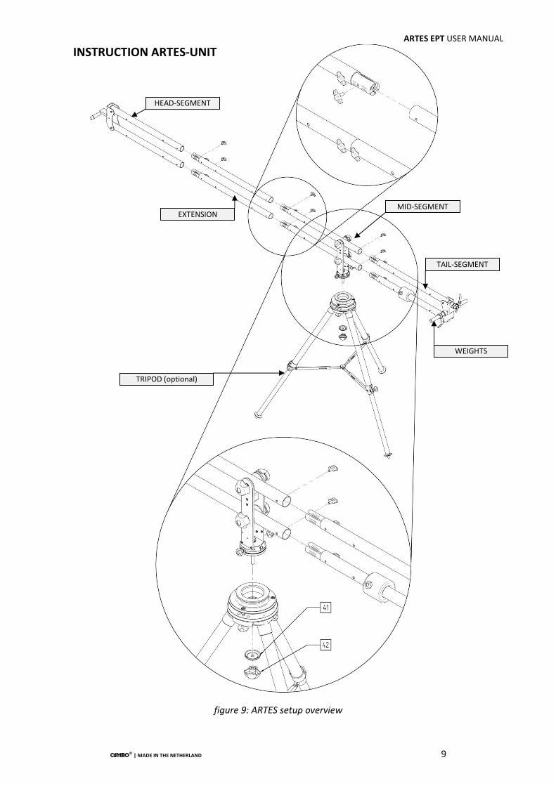
figure 9: ARTES setup overview
MID-SEGMENT
TAIL-SEGMENT
EXTENSION
TRIPOD (optional)
HEAD-SEGMENT
WEIGHTS
INSTRUCTION ARTES-UNIT

ARTES EPT USER MANUAL
CAMBO©
| MADE IN THE NETHERLAND 10
ITEM LIST ARTES Please note: these numbers only correspond to images 9 to 15.
1 Tube clamp 23 Hexagon Dome Nuts M6 (din1587)
2 Locking bolt tube clamp 24 Washer 6,4 (din125a1)
3 Tube segment (0,75m) 25 Hexagon Socket Head M6x75 din912
4 Reinforced tube segment 26 Front segment assembly
5 Nylon bearing disc 27 Brass bearing
6 Locking knob ARTES rotation 28 Adjustable counterweight
7 Teflon©
ring 29 Hexagon Socket Head M6x20 din912
8 Locking knob with axis 30 Washer 6,4 (din125a1) (same as #24)
9 Washer 10,5 (din125a1) 31 Rear-end profile (same as #22)
10 Locking knob ARTES movement 32 Clamp for EPT control frame
11 Mid-segment assembly 33 Hexagon Socket Head M8x20 din912
12 Hexagon Prevailing Torque Nut M4 (din985) 34 Washer 8,4 (din125a1)
13 Standard stud adapter (e.g. monitor arm) 35 Filling ring counterweights
14 Locking knob accessory stud 36 Locking ring counterweights
15 Cross Countersunk Screws M4x40 (din965) 37 Counterweights axis
16 End cap tube segment 38 Direct camera plate (if not using the EPT)
17 Handle and locking bolt EPT-unit 39 Hexagon Socket Head M5x16 din912
18 Adapter for EPT unit 40 Washer 5,3 (din125a1) (same as #19)
19 Washer 5,3 (din125a1) 41 Clamp ring tripod bowl
20 Hexagon Socket Head M5x16 (din912) 42 Knob clamp ring tripod bowl
21 Delrin©
filling ring
22 Front-end profile

ARTES EPT USER MANUAL
CAMBO©
| MADE IN THE NETHERLAND 11
figure 10: ARTES mid-segment
MID-SEGMENT

ARTES EPT USER MANUAL
CAMBO©
| MADE IN THE NETHERLAND 12
figure 12: ARTES head-segment
HEAD-SEGMENT

ARTES EPT USER MANUAL
CAMBO©
| MADE IN THE NETHERLAND 13
figure 11: ARTES tail-segment
TAIL-SEGMENT

ARTES EPT USER MANUAL
CAMBO©
| MADE IN THE NETHERLAND 14
figure 13: assembly steps ARTES
MID-SEGMENT
TAIL-SEGMENT
EXTENSION
TRIPOD
ASSEMBLY STEPS

ARTES EPT USER MANUAL
CAMBO©
| MADE IN THE NETHERLAND 15
figure 13: assembly steps ARTES
HEAD-SEGMENT
WEIGHTS
RIGHT DISTRIBUTION
WRONG DISTRIBUTION

ARTES EPT USER MANUAL
CAMBO©
| MADE IN THE NETHERLAND 16
Standard length (with 0,75m extension)
Short length (without 0,75m extension)
Compact setup (with 0,75m extension)
Compact setup short (without 0,75m extension)
figure 14: different ARTES setups
Load Specifications
• Load Capacity ARTES/EPT Standard Length: 4,5 kg (10 lbs)
• Load Capacity ARTES/EPT Short Length: 7,5 kg (16,5 lbs)
• Load Capacity ARTES/TILT Compact Standard: 7,5 kg (16,5 lbs)
• Load Capacity ARTES/TILT Compact Short: 12 kg (26,5 lbs)
• Load Capacity EPT (on tripod): 7,5 kg (16,5 lbs)
Spectifications EPT-unit
• Head Unit weight: 3 kg (6,5 lbs)
• Head Dimensions: 44x31x13cm (17x12x5")
• Durable brushless motors
• Black anodised aluminium
• Standard UTP for communication and power cable
• Power requirement 12 -14,8 V DC
• Tripod (3/8")mount option
Spectifications ARTES-unit
(excl. EPT head and counterweights)
• Weight ARTES Standard Length 9,6 kg
• Weight ARTES Short Length 8,1 kg
• Weight ARTES Compact Standard Length 8,1 kg
• Weight ARTES Short Length 6,6 kg
• Black anodised aluminium

ARTES EPT USER MANUAL
CAMBO©
| MADE IN THE NETHERLAND 17
figure 15: Fixed camera plate, alternative setup head-segment ARTES
CAMBO
This instruction manual is prepared with care, although no responsibility, financial or otherwise, is accepted for any consequences related the
information stated in this instruction manual. All specifications in this instruction manual are subject to change without notice.
For more information please visit the Cambo website: www.cambo.com
OPTIONAL ARTES-TILT SETUP
FIXED CAMERA PLATE HEAD SEGMENT (when not using the EPT head)