manual - baha enerji thytronic/na011 thytronic... · na011- manual - 05 - 2010 manual na011 phase...
TRANSCRIPT

NA011- Manual - 05 - 2010
MANUAL
NA011PHASE & RESIDUAL OVERCURRENT,
AUTOMATIC RECLOSUREPROTECTION RELAY
22 NA011 - Manual - 05 - 2010
TABLE OF CONTENTS
1 INTRODUCTION 5Scope and liability ...........................................................................................................................................................................................5Applicability ......................................................................................................................................................................................................5Conformity ........................................................................................................................................................................................................5Technical support ............................................................................................................................................................................................5Copyright ...........................................................................................................................................................................................................5Warranty ...........................................................................................................................................................................................................5Safety recommendations ...............................................................................................................................................................................5Insulation tests ................................................................................................................................................................................................5Product identification .....................................................................................................................................................................................6Environment .....................................................................................................................................................................................................6Graphical conventions ...................................................................................................................................................................................6Glossary/definitions ........................................................................................................................................................................................6
2 GENERAL 10Preface ........................................................................................................................................................................................................... 10Photo .............................................................................................................................................................................................................. 10Main features .................................................................................................................................................................................................11
3 TECHNICAL DATA 123.1 GENERAL ............................................................................................................................................................................................................12
Mechanical data ...........................................................................................................................................................................................12Insulation ........................................................................................................................................................................................................12EMC tests for interference immunity .........................................................................................................................................................12Voltage dip and interruption ........................................................................................................................................................................12EMC tests for interference immunity .........................................................................................................................................................12Emission ......................................................................................................................................................................................................... 13Mechanical tests .......................................................................................................................................................................................... 13Climatic tests ................................................................................................................................................................................................. 13Safety ............................................................................................................................................................................................................. 13Certifications ................................................................................................................................................................................................. 13
3.2 INPUT CIRCUITS ...............................................................................................................................................................................................14Auxiliary power supply U aux .......................................................................................................................................................................14Phase current input circuits ........................................................................................................................................................................14Residual current input circuit ......................................................................................................................................................................14Binary input circuits ......................................................................................................................................................................................14
3.3 OUTPUT CIRCUITS ............................................................................................................................................................................................14Output relays ..................................................................................................................................................................................................14
3.4 MMI .....................................................................................................................................................................................................................153.5 COMMUNICATION INTERFACES ...................................................................................................................................................................15
Local port ........................................................................................................................................................................................................15Remote ports ..................................................................................................................................................................................................15
3.6 GENERAL SETTINGS ........................................................................................................................................................................................15 3.7 PROTECTIVE ELEMENTS .................................................................................................................................................................................15
Phase overcurrent - 50/51 ............................................................................................................................................................................15Residual overcurrent - 50N/51N .................................................................................................................................................................17
3.8 CONTROL AND MONITORING ....................................................................................................................................................................... 18Circuit Breaker monitoring ......................................................................................................................................................................... 18Oscillography (DFR) ..................................................................................................................................................................................... 18
3.9 MEASURES ....................................................................................................................................................................................................... 18Measures ....................................................................................................................................................................................................... 18Digital inputs ................................................................................................................................................................................................. 18Automatic Reclose ....................................................................................................................................................................................... 18Circuit Breaker .............................................................................................................................................................................................. 18
4 FUNCTION CHARACTERISTICS 194.1 HARDWARE DESCRIPTION ............................................................................................................................................................................ 19
Power supply board ..................................................................................................................................................................................... 19CPU board ...................................................................................................................................................................................................... 20Input board .................................................................................................................................................................................................... 20MMI (keyboard, LED and display) ............................................................................................................................................................. 20
4.2 SOFTWARE DESCRIPTION ..............................................................................................................................................................................21Kernel ..............................................................................................................................................................................................................21Drivers .............................................................................................................................................................................................................21Application......................................................................................................................................................................................................21Base protocol (kernel) ..................................................................................................................................................................................21Calibration (kernel) ........................................................................................................................................................................................21
3NA011 - Manual - 05 - 2010
Communication (drivers) ..............................................................................................................................................................................21MMI (drivers) .................................................................................................................................................................................................21Data Base (application/drivers) ..................................................................................................................................................................22Self-test (application) ...................................................................................................................................................................................22Development tools ........................................................................................................................................................................................22
4.3 I/O DESCRIPTION ............................................................................................................................................................................................. 23Metering inputs ............................................................................................................................................................................................ 23Signal processing ......................................................................................................................................................................................... 23Use of measured values ...............................................................................................................................................................................24Binary inputs ..................................................................................................................................................................................................25Output relays ..................................................................................................................................................................................................26LED indicators ................................................................................................................................................................................................27Communication interfaces .......................................................................................................................................................................... 28
4.4 PROTECTIVE ELEMENTS ................................................................................................................................................................................ 29Phase overcurrent - 50/51 ............................................................................................................................................................................31Residual overcurrent - 50N/51N .................................................................................................................................................................34Breaker failure - BF .......................................................................................................................................................................................37
4.5 CONTROL AND MONITORING ....................................................................................................................................................................... 38Circuit breaker supervision ........................................................................................................................................................................ 38Circuit breaker commands ......................................................................................................................................................................... 38Automatic reclosure - 79 ............................................................................................................................................................................. 39 Test ................................................................................................................................................................................................................. 43Oscillography ............................................................................................................................................................................................... 43
5 MEASURES, LOGIC STATES AND COUNTERS 44Measures ........................................................................................................................................................................................................44Circuit breaker ...............................................................................................................................................................................................44Counters ..........................................................................................................................................................................................................44Fault recording - SFR ....................................................................................................................................................................................44Event recording - Events ..............................................................................................................................................................................44Info ...................................................................................................................................................................................................................45Protections trip ..............................................................................................................................................................................................45Self-test ...........................................................................................................................................................................................................45Oscillography - DFR ......................................................................................................................................................................................45
6 INSTALLATION 476.1 PACKAGING .......................................................................................................................................................................................................476.2 MOUNTING ........................................................................................................................................................................................................476.3 ELECTRICAL CONNECTIONS ......................................................................................................................................................................... 496.4 NOMINAL CURRENT In AND IEn SETTINGS ................................................................................................................................................546.5 NOMINAL CURRENT In SETTING FOR LPCT ...............................................................................................................................................566.6 LED ALLOCATION ..............................................................................................................................................................................................576.7 FINAL OPERATIONS .........................................................................................................................................................................................57
7 PROGRAMMING AND SETTINGS 587.1 SW ThySetter.................................................................................................................................................................................................... 58
ThySetter installation ................................................................................................................................................................................... 58ThySetter use ................................................................................................................................................................................................ 58
7.2 MMI (Man Machine Interface) ..................................................................................................................................................................... 59Reading variables (READ) ........................................................................................................................................................................... 59Setting modifying (SET) ............................................................................................................................................................................... 59Test .................................................................................................................................................................................................................. 60Communication ..............................................................................................................................................................................................61Reset ................................................................................................................................................................................................................61DEFAULT (Option) ..........................................................................................................................................................................................61Data/time setting (Time) ...............................................................................................................................................................................61Circuit breaker commands ..........................................................................................................................................................................61
7.3 MENU TREE........................................................................................................................................................................................................627.4 MAINTENANCE .................................................................................................................................................................................................677.5 REPAIR ................................................................................................................................................................................................................677.6 PACKAGING .......................................................................................................................................................................................................67
8 APPENDIX 688.1 APPENDIX A1 - Inverse time IEC curves .................................................................................................................................................... 68
Mathematical formula ................................................................................................................................................................................. 68Phase overcurrent 50/51 - Standard inverse time curve (IEC 60255-3/BS142 type A) ..................................................................... 69Phase overcurrent 50/51 - Very inverse time curve (IEC 60255-3/BS142 type B) ............................................................................. 70Phase overcurrent 50/51 - Extremely inverse time curve (IEC 60255-3/BS142 type C) .....................................................................71Residual overcurrent 50N/51N - Standard inverse time curve (IEC 60255-3/BS142 type A) ...........................................................72Residual overcurrent 50N/51N - Very inverse time curve (IEC 60255-3/BS142 type B) ................................................................... 73

44 NA011 - Manual - 05 - 2010
Residual overcurrent 50N/51N - Extremely inverse time curve (IEC 60255-3/BS142 type C) ..........................................................748.2 APPENDIX A2 - Inverse time ANSI/IEEE curves .........................................................................................................................................75
Mathematical formula ..................................................................................................................................................................................75Phase overcurrent 50/51 - Moderately inverse time curve (ANSI/IEEE type MI) ..............................................................................76Phase overcurrent 50/51 - Very inverse time curve (ANSI/IEEE type VI) ...........................................................................................77Phase overcurrent 50/51 - Extremely inverse time curve (ANSI/IEEE type EI) ................................................................................. 78Residual overcurrent 50N/51N - Moderately inverse time curve (ANSI/IEEE type MI) .................................................................. 79Residual overcurrent 50N/51N - Very inverse time curve (ANSI/IEEE type VI) ................................................................................ 80Residual overcurrent 50N/51N - Extremely inverse time curve (ANSI/IEEE type EI) ........................................................................81
8.3 APPENDIX B1 - I/O Diagram ...........................................................................................................................................................................828.4 APPENDIX B2 - Interfaces ............................................................................................................................................................................. 838.5 APPENDIX B3 - Connection diagrams ..........................................................................................................................................................848.6 APPENDIX C - Dimensions ............................................................................................................................................................................. 888.7 APPENDIX D - Revisions history ................................................................................................................................................................... 898.8 APPENDIX E - EC Declaration of conformity ............................................................................................................................................... 90

5NA011 - Manual - 05 - 2010INTRODUCTION
1 I N T R O D U C T I O N1 I N T R O D U C T I O NScope and liability
This document describes the functions, the technical data of NA011 devices; instructions for mount-ing, setting and commissioning are included.This manual has been checked out, however, deviations from the description cannot be completely ruled out, so that no liability in a legal sense for correctness and completeness of the information or from any damage that might result from its use is formally disclaimed.The information given in this document is reviewed regularly; any corrections and integration will be included in subsequent editions that are identifi ed by the date of revision.We appreciate any suggestions for improvement.We reserve the right to make technical improvements without notice.
ApplicabilityThis manual is valid for NA011 devices with fi rmware version 1.00 and following.Revision history is listed in appendix.
ConformityThe product complies with the CEE directives:
EMC Council Directives: 89/336/EECLow voltage Directives: 73/23/EEC
Technical supportContact: THYTRONIC Technical Service www.thytronic.it
CopyrightAll right reserved; It is forbidden to copy, modify or store material (document and sw) protected by copyright without Thytronic consent.
WarrantyThytronic warrants devices against defects in materials and workmanship under normal use for a period of ONE (1) YEAR from the date of retail purchase by the original end-user purchaser (“War-ranty Period”).
Safety recommendationsThe warming contained in this document are all-important for safety; special attention must be paid to the following symbols:
Installation and commissioning must be carried out by qualifi ed person; Thytronic assumes no re-sponsibility for damages caused from improper use that does not comply all warning and caution in this manual.In particular the following requirements must be met:
Remove power before opening it.Verify the voltage absence by means suitable instrumentation on relay connections; attention must be paid to all circuits supplied by external sources (binary input, CT, etc...) Care must be taken when handling metal parts (front panel, connectors).
Insulation testsAfter insulation tests, hazardous voltages (capacitor charges,...) may be arise; it is advisable to grad-ually reduce the test voltage avoiding to erase it abruptly.
••
••
•
WARNING Death, severe personal injury or substantial property damage can result if proper precautionsare not taken.WARNING Death, severe personal injury or substantial property damage can result if proper precautionsare not taken.
CAUTION Minor personal injury or property damage can result if proper precautions are not takenCAUTION Minor personal injury or property damage can result if proper precautions are not taken
CAUTIONSettings must be established on the basis of a coordination study.Numerical values inside examples have educational purpose only; they don’t be used, in no way,for actual applications.
CAUTIONSettings must be established on the basis of a coordination study.Numerical values inside examples have educational purpose only; they don’t be used, in no way,for actual applications.

66 NA011 - Manual - 05 - 2010 INTRODUCTION
Product identifi cationEach device is equipped with:
Identifi cation label installed on the front side with following informations: code number, phase and residual nominal currents, auxiliary voltage range and CE mark:
Test label with following informations: data, serial number and test operator signature.
EnvironmentThe NA011 device must be employed according to the environment conditions shown (see technical data).In case of different environment conditions, appropriate provisions must be provided (conditioning system, humidity control, etc...).If contaminants are present (dust, corrosive substances, etc...), filters must be provided.
Graphical conventionsThe CEI/IEC and ANSI symbols is employed where possible:e.g.: 51 = ANSI code concerning the overcurrent element.Following text formats are used:The ThySetter[1] menu: Phase overcurrent -50/51The parameter description (measures, thresholds, operate time,...) and related value: First threshold 50/51 defi nite time I>defThe display messages (MMI) are shown as: NA011Notes are highlighted with cursive letters inside colored bar
Note: Useful description note
Glossary/defi nitionsI En Relay residual nominal currentI Enp Residual CT primary nominal currentI n Relay phase nominal currentI np Phase CT primary nominal current50/51 Phase overcurrent ANSI code50N/51N Residual overcurrent ANSI code79 Automatic reclosing
DFR Digital Fault Recorder (Oscillography)SER Sequential Event RecorderSFR Sequential Fault RecorderANSI American National Standard InstituteIEEE Institute of Electrical and Electronics EngineersIEC International Electrotechnical CommissionCENELEC Comité Européen de Normalisation Electrotechnique
Note 1 The graphic interface and the operation of the ThySetter software are described in the relative chapters
•
•
NA011#xxx0
In 5A 1A
50-5150N-51NCB OPENCB CLOSED79
5A
UAUX 24-230 Vac/dc12345
NA011#xxx1
IIn
n
Rated 50...500AExtended 50...1250A
50-5150N-51NCB OPENCB CLOSED79
UAUX 24-230 V12345
NA011#xxx2
In 5A 1A
50-5150N-51NCB OPENCB CLOSED79
5A
UAUX 24-230 Vac/dcIEn 1A 1A 5A
12345
NA011#xxx3
IIn
n
Rated 50...500AExtended 50...1250A
50-5150N-51NCB OPENCB CLOSED79
IEn 1A 1A 5A UAUX 24-230 V12345
7NA011 - Manual - 05 - 2010INTRODUCTION
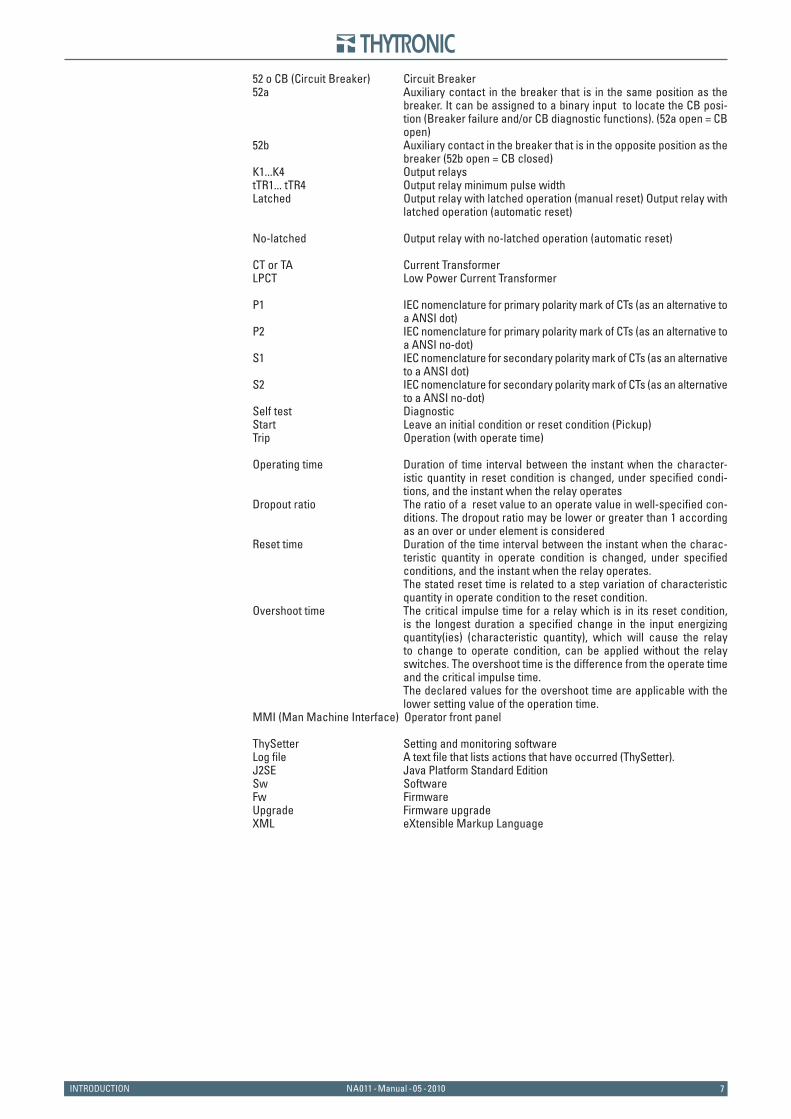
52 o CB (Circuit Breaker) Circuit Breaker52a Auxiliary contact in the breaker that is in the same position as the
breaker. It can be assigned to a binary input to locate the CB posi-tion (Breaker failure and/or CB diagnostic functions). (52a open = CB open)
52b Auxiliary contact in the breaker that is in the opposite position as the breaker (52b open = CB closed)
K1...K4 Output relaystTR1... tTR4 Output relay minimum pulse widthLatched Output relay with latched operation (manual reset) Output relay with
latched operation (automatic reset)
No-latched Output relay with no-latched operation (automatic reset)
CT or TA Current TransformerLPCT Low Power Current Transformer
P1 IEC nomenclature for primary polarity mark of CTs (as an alternative to a ANSI dot)
P2 IEC nomenclature for primary polarity mark of CTs (as an alternative to a ANSI no-dot)
S1 IEC nomenclature for secondary polarity mark of CTs (as an alternative to a ANSI dot)
S2 IEC nomenclature for secondary polarity mark of CTs (as an alternative to a ANSI no-dot)
Self test DiagnosticStart Leave an initial condition or reset condition (Pickup)Trip Operation (with operate time)
Operating time Duration of time interval between the instant when the character-istic quantity in reset condition is changed, under specifi ed condi-tions, and the instant when the relay operates
Dropout ratio The ratio of a reset value to an operate value in well-specifi ed con-ditions. The dropout ratio may be lower or greater than 1 according as an over or under element is considered
Reset time Duration of the time interval between the instant when the charac-teristic quantity in operate condition is changed, under specifi ed conditions, and the instant when the relay operates.
The stated reset time is related to a step variation of characteristic quantity in operate condition to the reset condition.
Overshoot time The critical impulse time for a relay which is in its reset condition, is the longest duration a specifi ed change in the input energizing quantity(ies) (characteristic quantity), which will cause the relay to change to operate condition, can be applied without the relay switches. The overshoot time is the difference from the operate time and the critical impulse time.
The declared values for the overshoot time are applicable with the lower setting value of the operation time.
MMI (Man Machine Interface) Operator front panel
ThySetter Setting and monitoring softwareLog fi le A text fi le that lists actions that have occurred (ThySetter).J2SE Java Platform Standard EditionSw SoftwareFw FirmwareUpgrade Firmware upgradeXML eXtensible Markup Language

88 NA011 - Manual - 05 - 2010 INTRODUCTION
Symbols.ai
Symbols
I>> Star t
I>> BF_OUT
IPh Block2
Logic internal signal (output); may be a logical state (e .g . I>> Star t) or a numerical valueIt is available for reading (ThySetter + communication interface)
Logic external signal (intput); may be a command coming from a binary input or a sw commandIt is available for reading (ThySetter + communication interface)
Internal signal (e.g. Breaker Failure output state concerning to the 2nd threshold of the 50 element) It is not available for reading (missing arrow)
AND and NAND logic gates
OR and NOR logic gates
Limit block (I>> threshold).
Computation block (Max phase current)
Threshold setting (e.g. pickup I >>).The value is available for reading and is adjustable by means ThySetter + MMI.
Switch
ON delay timer with reset (tON delay)
ON delay timer without reset (tON delay)
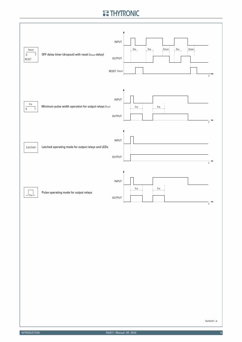
OFF delay timer (dropout) without reset (tDROP delay)
Curve type (definite/inverse time)0T
I L3
M a x [ I L1 ,I L2 ,I L3 ]I L2
I L1
tON tON tON tON
t
RESET
INPUT
OUTPUT
tDROPtON tON
t
INPUT
OUTPUT
tON tON tON
t
INPUT
OUTPUT
0TtON
& &
≥1 ≥1
EXOR logic gate
tDROP
=1
I >>
II ≥ I >>
tON
RESET
0T
0 T
9NA011 - Manual - 05 - 2010INTRODUCTION
Symbols1 .ai
tON tON tON
t
RESET
INPUT
OUTPUT
tDROP
tDROP
tDROP tDROP
Minimum pulse width operation for output relays (tTR) tTR
t
tTR
INPUT
OUTPUT
tTR
0 T
tTR
t
tTR
INPUT
OUTPUT
Latched operating mode for output relays and LEDs
Pulse operating mode for output relays
t
INPUT
OUTPUT
Latched
tTR
T0RESET
OFF delay timer (dropout) with reset (tDROP delay)

1010 NA011 - Manual - 05 - 2010 GENERAL
2 G E N E R A L2 G E N E R A LPreface
The relay type NA011 can be used in radial networks as feeder or power transformer protection. In solidly grounded systems the residual overcurrent protection can be used on feeders of any length, while in ungrounded or Petersen coil and/or resistance grounded systems, the residual overcurrent protection can be used on feeders of small length in order to avoid unwanted trippings due to the capacitive current contribution of the feeder on external ground fault.Beside to the phase and residual overcurrent protections, the automatic reclosing function is pro-vided.The NA011 protection relay may be shipped with traditional CTs or low power (LPCT) current inputs; for both versions, the residual overcurrent protection can use the measured (CTs or balanced trans-former) or the calculated residual current.
Following input circuits are available:Phase current inputs
Traditional CTsThree phase current inputs with secondary nominal currents independently selectable at 1 A or 5 A through DIP-switches.
Low power CTsThree phase current inputs with primary nominal currents independently selectable through DIP-switches and software.
Residual current inputMeasured residual current
One residual current input with secondary nominal current selectable at 1 A or 5 A through DIP-switches.
Calculated residual currentResidual current is calculated by the vector sum of the three phase currents, measured by three 1 A or 5 A CTs or by three LPCT type sensors.
Setting, programming and reading operations must be effected by means of Personal Computer with ThySetter software or by means of remote communication interface (RS485 bus); all operations must be performed through MMI.The NA011 hardware case is suitable for fl ash and rack mountingOther options are:
Auxiliary power supply operating range.Communication protocols (Modbus or IEC60870-5-103).
Photo
•
•
•
•
••

11NA011 - Manual - 05 - 2010GENERAL
Main featuresMetallic case. Backlight LCD 2x16 Display.Eight LEDs that may be joined with matrix criteria to many and various functions.RESET key to clear LED indications and latched output relays.Three binary inputs.Independently settable for start, trip, self-test and control four output relay (K1...K4) Each output relay may be set with normally energized or normally de-energized operating mode and manual or automatic reset (latched/no-latched).Rear RS485 port, with ModBus protocol.RS232 front serial port (local communication for Thysetter).Real time clock with super capacitor backup.
The most signifi cant constructive features are:Galvanically insulated input and output circuits (communication and binary circuits included).Fast sampling rate for inputs.Optimum fi ltering of input signals through combined use of analog and digital fi lters.Traditional electromechanical-type fi nal output contacts with continuous monitoring of control coil continuity.Auxiliary supply comprising a switching-type voltage stabilizing circuit having a very wide working range and a very small power dissipationNominal frequency: 50 or 60 Hz.
The most signifi cant operating features are:Programming of operating modes and parameters by means of the front keys and alphanumeric display, with a programming procedure based on carrying out guided selections and on explicit and immediate signalling of the operations being performed, so that such procedure can be carried out without coding tables or mnemonic informations.The feature modifi cation operations do not interrupt the normal functions of the relay.Impossibility of programming unacceptable parameter values, thanks to the automatic limitation of top and bottom scale values for the relative setting ranges.Currents are sampled 64 times per period and measured in the effective value (RMS) of the funda-mental component using the DFT (Discrete Fourier Transform) algorithm and digital fi lters.The fault recorder (SFR) runs continuously capturing in circular mode the last twenty events upon trigger of binary input/output and/or element pickup (start-trip).The event recorder (SER) runs continuously capturing in circular mode the last three hundred events upon trigger of binary input/output.Digital fault recorder (DFR) in COMTRADE format (oscillography).
••••••
•••
••••
•
•
•
••
•
•
•
•
1212 NA011 - Manual - 05 - 2010 TECHNICAL DATA
3 T E C H N I C A L D A T A3 T E C H N I C A L D A T A
3.1 GENERAL
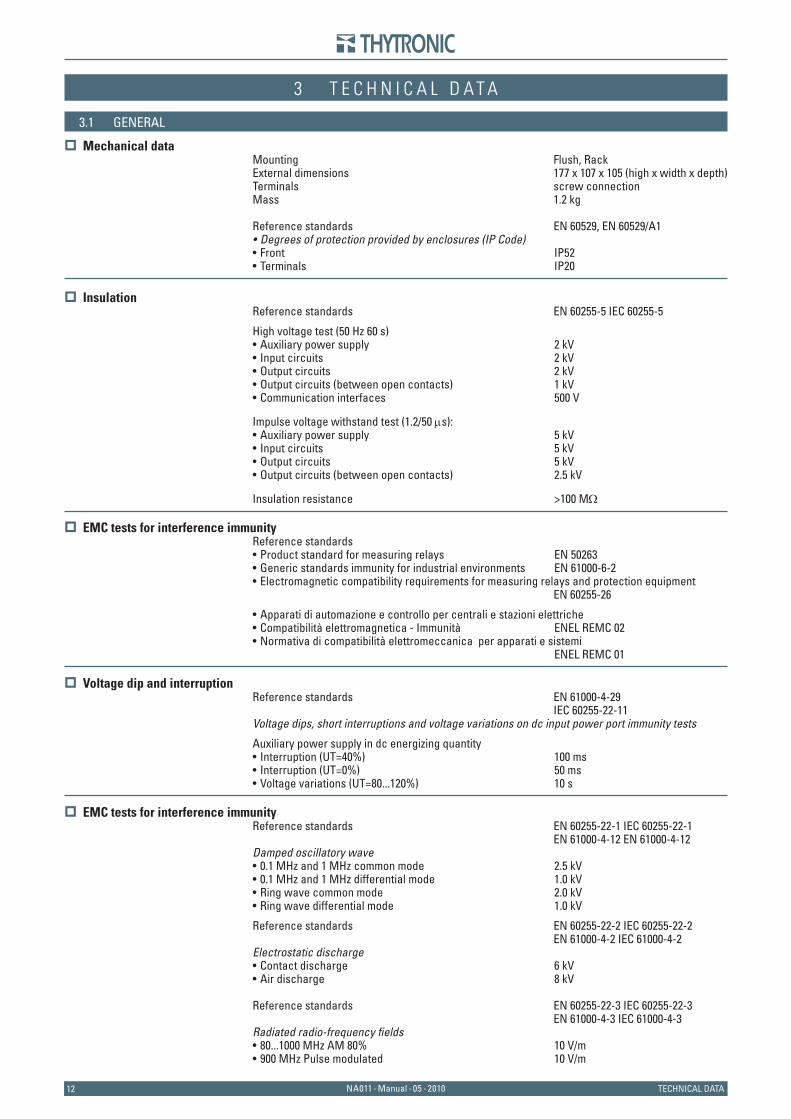
Mechanical dataMounting Flush, RackExternal dimensions 177 x 107 x 105 (high x width x depth)Terminals screw connectionMass 1.2 kg
Reference standards EN 60529, EN 60529/A1Degrees of protection provided by enclosures (IP Code)Front IP52Terminals IP20
Insulation
Reference standards EN 60255-5 IEC 60255-5
High voltage test (50 Hz 60 s) Auxiliary power supply 2 kVInput circuits 2 kVOutput circuits 2 kVOutput circuits (between open contacts) 1 kVCommunication interfaces 500 V
Impulse voltage withstand test (1.2/50 μs):Auxiliary power supply 5 kVInput circuits 5 kVOutput circuits 5 kVOutput circuits (between open contacts) 2.5 kV
Insulation resistance >100 MΩ
EMC tests for interference immunityReference standards
Product standard for measuring relays EN 50263Generic standards immunity for industrial environments EN 61000-6-2Electromagnetic compatibility requirements for measuring relays and protection equipment
EN 60255-26
Apparati di automazione e controllo per centrali e stazioni elettricheCompatibilità elettromagnetica - Immunità ENEL REMC 02
• Normativa di compatibilità elettromeccanica per apparati e sistemi ENEL REMC 01
Voltage dip and interruption
Reference standards EN 61000-4-29 IEC 60255-22-11Voltage dips, short interruptions and voltage variations on dc input power port immunity tests
Auxiliary power supply in dc energizing quantity Interruption (UT=40%) 100 msInterruption (UT=0%) 50 ms
• Voltage variations (UT=80...120%) 10 s
EMC tests for interference immunityReference standards EN 60255-22-1 IEC 60255-22-1 EN 61000-4-12 EN 61000-4-12Damped oscillatory wave
0.1 MHz and 1 MHz common mode 2.5 kV0.1 MHz and 1 MHz differential mode 1.0 kVRing wave common mode 2.0 kVRing wave differential mode 1.0 kV
Reference standards EN 60255-22-2 IEC 60255-22-2 EN 61000-4-2 IEC 61000-4-2Electrostatic discharge
Contact discharge 6 kVAir discharge 8 kV
Reference standards EN 60255-22-3 IEC 60255-22-3 EN 61000-4-3 IEC 61000-4-3Radiated radio-frequency fi elds
80...1000 MHz AM 80% 10 V/m 900 MHz Pulse modulated 10 V/m
•••
•••••
••••
•••
••
••
••••
••
••
13NA011 - Manual - 05 - 2010TECHNICAL DATA
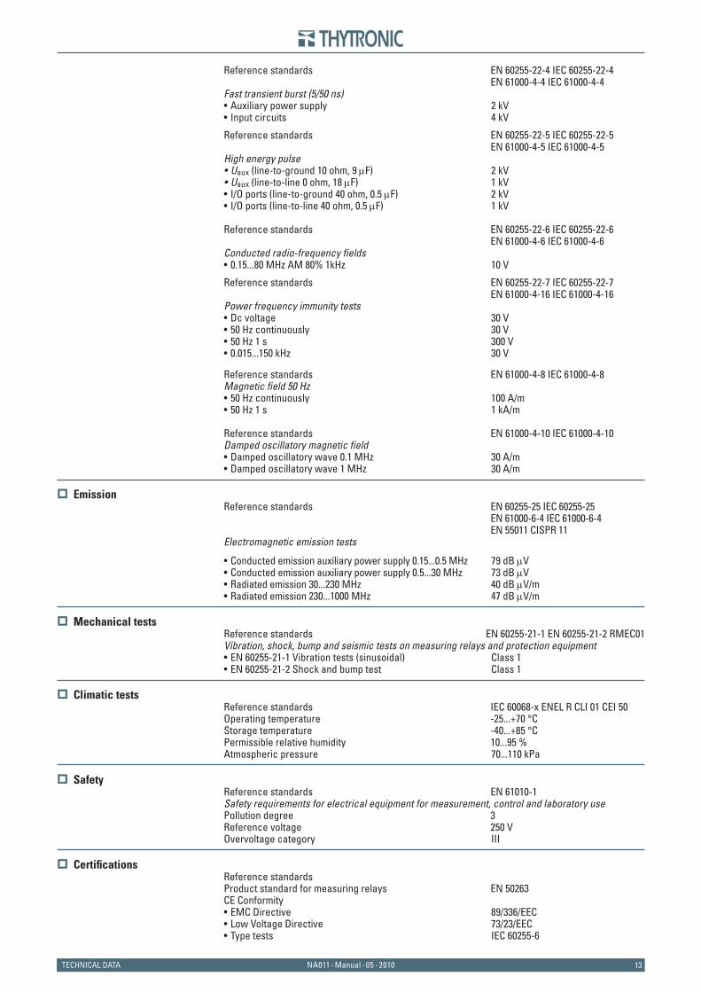
Reference standards EN 60255-22-4 IEC 60255-22-4 EN 61000-4-4 IEC 61000-4-4 Fast transient burst (5/50 ns)
Auxiliary power supply 2 kVInput circuits 4 kV
Reference standards EN 60255-22-5 IEC 60255-22-5 EN 61000-4-5 IEC 61000-4-5High energy pulse
Uaux (line-to-ground 10 ohm, 9 μF) 2 kVUaux (line-to-line 0 ohm, 18 μF) 1 kVI/O ports (line-to-ground 40 ohm, 0.5 μF) 2 kVI/O ports (line-to-line 40 ohm, 0.5 μF) 1 kV
Reference standards EN 60255-22-6 IEC 60255-22-6 EN 61000-4-6 IEC 61000-4-6Conducted radio-frequency fi elds
0.15...80 MHz AM 80% 1kHz 10 V
Reference standards EN 60255-22-7 IEC 60255-22-7 EN 61000-4-16 IEC 61000-4-16Power frequency immunity tests
Dc voltage 30 V50 Hz continuously 30 V50 Hz 1 s 300 V0.015...150 kHz 30 V
Reference standards EN 61000-4-8 IEC 61000-4-8Magnetic fi eld 50 Hz
50 Hz continuously 100 A/m50 Hz 1 s 1 kA/m
Reference standards EN 61000-4-10 IEC 61000-4-10Damped oscillatory magnetic fi eld
Damped oscillatory wave 0.1 MHz 30 A/m• Damped oscillatory wave 1 MHz 30 A/m
Emission
Reference standards EN 60255-25 IEC 60255-25 EN 61000-6-4 IEC 61000-6-4 EN 55011 CISPR 11Electromagnetic emission tests
Conducted emission auxiliary power supply 0.15...0.5 MHz 79 dB μVConducted emission auxiliary power supply 0.5...30 MHz 73 dB μVRadiated emission 30...230 MHz 40 dB μV/m
• Radiated emission 230...1000 MHz 47 dB μV/m
Mechanical testsReference standards EN 60255-21-1 EN 60255-21-2 RMEC01Vibration, shock, bump and seismic tests on measuring relays and protection equipment
EN 60255-21-1 Vibration tests (sinusoidal) Class 1• EN 60255-21-2 Shock and bump test Class 1
Climatic tests
Reference standards IEC 60068-x ENEL R CLI 01 CEI 50Operating temperature -25...+70 °CStorage temperature -40...+85 °CPermissible relative humidity 10...95 %Atmospheric pressure 70...110 kPa
Safety
Reference standards EN 61010-1Safety requirements for electrical equipment for measurement, control and laboratory usePollution degree 3Reference voltage 250 VOvervoltage category III
Certifi cationsReference standardsProduct standard for measuring relays EN 50263 CE Conformity
EMC Directive 89/336/EECLow Voltage Directive 73/23/EECType tests IEC 60255-6
••
••••
•
••••
••
•
•••
•
•••
1414 NA011 - Manual - 05 - 2010 TECHNICAL DATA
3.2 INPUT CIRCUITS
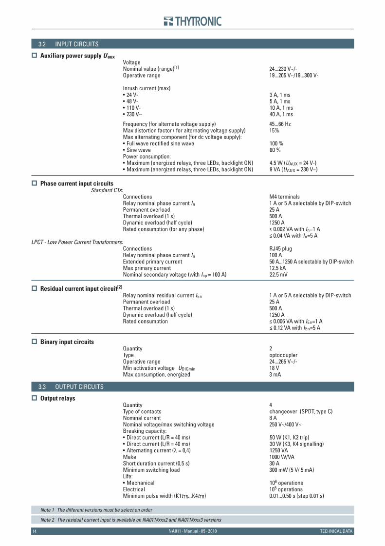
Auxiliary power supply U aux VoltageNominal value (range)[1] 24...230 V~/-Operative range 19...265 V~/19...300 V-
Inrush current (max)24 V- 3 A, 1 ms48 V- 5 A, 1 ms110 V- 10 A, 1 ms230 V~ 40 A, 1 ms
Frequency (for alternate voltage supply) 45...66 HzMax distortion factor ( for alternating voltage supply) 15%Max alternating component (for dc voltage supply):
Full wave rectifi ed sine wave 100 %Sine wave 80 %
Power consumption: Maximum (energized relays, three LEDs, backlight ON) 4.5 W (UAUX = 24 V-)
• Maximum (energized relays, three LEDs, backlight ON) 9 VA (UAUX = 230 V~)
Phase current input circuitsStandard CTs:
Connections M4 terminalsRelay nominal phase current In 1 A or 5 A selectable by DIP-switchPermanent overload 25 AThermal overload (1 s) 500 ADynamic overload (half cycle) 1250 ARated consumption (for any phase) ≤ 0.002 VA with In=1 A ≤ 0.04 VA with In=5 A
LPCT - Low Power Current Transformers:Connections RJ45 plugRelay nominal phase current In 100 AExtended primary current 50 A...1250 A selectable by DIP-switchMax primary current 12.5 kANominal secondary voltage (with Inp = 100 A) 22.5 mV
Residual current input circuit[2]
Relay nominal residual current IEn 1 A or 5 A selectable by DIP-switch Permanent overload 25 AThermal overload (1 s) 500 ADynamic overload (half cycle) 1250 ARated consumption ≤ 0.006 VA with IEn=1 A ≤ 0.12 VA with IEn=5 A
Binary input circuitsQuantity 2Type optocouplerOperative range 24...265 V~/-Min activation voltage UDIGmin 18 VMax consumption, energized 3 mA
3.3 OUTPUT CIRCUITS
Output relaysQuantity 4Type of contacts changeover (SPDT, type C) Nominal current 8 ANominal voltage/max switching voltage 250 V~/400 V~Breaking capacity:
Direct current (L/R = 40 ms) 50 W (K1, K2 trip)Direct current (L/R = 40 ms) 30 W (K3, K4 signalling)Alternating current (λ = 0,4) 1250 VA
Make 1000 W/VAShort duration current (0,5 s) 30 AMinimum switching load 300 mW (5 V/ 5 mA)Life:
Mechanical 106 operationsElectrical 105 operationsMinimum pulse width (K1tTR...K4tTR) 0.01...0.50 s (step 0.01 s)
Note 1 The different versions must be select on order
Note 2 The residual current input is available on NA011#xxx2 and NA011#xxx3 versions
••••
••
•
•••
•
15NA011 - Manual - 05 - 2010TECHNICAL DATA
3.4 MMI
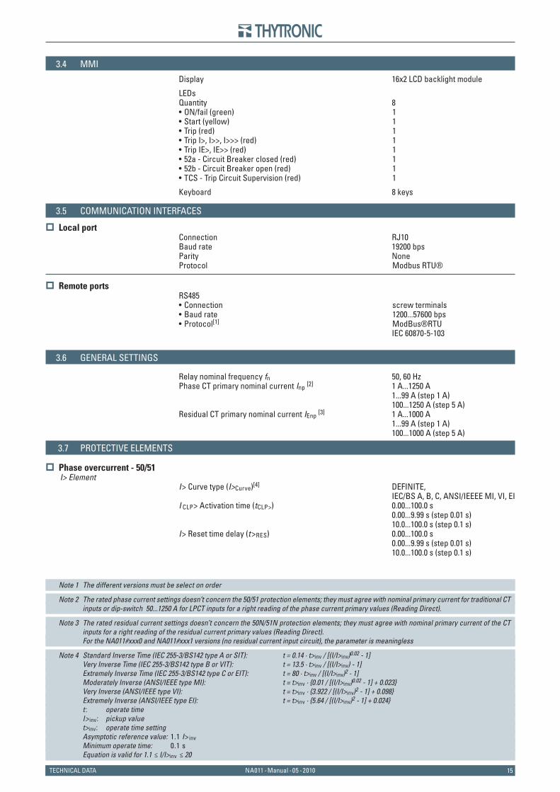
Display 16x2 LCD backlight module
LEDs Quantity 8
ON/fail (green) 1Start (yellow) 1Trip (red) 1Trip I>, I>>, I>>> (red) 1Trip IE>, IE>> (red) 152a - Circuit Breaker closed (red) 152b - Circuit Breaker open (red) 1TCS - Trip Circuit Supervision (red) 1
Keyboard 8 keys
3.5 COMMUNICATION INTERFACES
Local portConnection RJ10Baud rate 19200 bpsParity NoneProtocol Modbus RTU®
Remote ports
RS485Connection screw terminalsBaud rate 1200...57600 bpsProtocol[1] ModBus®RTU
IEC 60870-5-103
3.6 GENERAL SETTINGS
Relay nominal frequency fn 50, 60 HzPhase CT primary nominal current Inp [2] 1 A...1250 A 1...99 A (step 1 A) 100...1250 A (step 5 A)Residual CT primary nominal current IEnp [3] 1 A...1000 A 1...99 A (step 1 A) 100...1000 A (step 5 A)
3.7 PROTECTIVE ELEMENTS
Phase overcurrent - 50/51I> Element
I> Curve type (I>Curve)[4] DEFINITE, IEC/BS A, B, C, ANSI/IEEEE MI, VI, EII CLP> Activation time (tCLP>) 0.00...100.0 s 0.00...9.99 s (step 0.01 s) 10.0...100.0 s (step 0.1 s)I> Reset time delay (t>RES) 0.00...100.0 s 0.00...9.99 s (step 0.01 s) 10.0...100.0 s (step 0.1 s)
Note 1 The different versions must be select on order
Note 2 The rated phase current settings doesn’t concern the 50/51 protection elements; they must agree with nominal primary current for traditional CT inputs or dip-switch 50...1250 A for LPCT inputs for a right reading of the phase current primary values (Reading Direct).
Note 3 The rated residual current settings doesn’t concern the 50N/51N protection elements; they must agree with nominal primary current of the CT inputs for a right reading of the residual current primary values (Reading Direct).
For the NA011#xxx0 and NA011#xxx1 versions (no residual current input circuit), the parameter is meaningless
Note 4 Standard Inverse Time (IEC 255-3/BS142 type A or SIT): t = 0.14 · t>inv / [(I/I>inv)0.02 - 1] Very Inverse Time (IEC 255-3/BS142 type B or VIT): t = 13.5 · t>inv / [(I/I>inv) - 1] Extremely Inverse Time (IEC 255-3/BS142 type C or EIT): t = 80 · t>inv / [(I/I>inv)2 - 1] Moderately Inverse (ANSI/IEEE type MI): t = t>inv · {0.01 / [(I/I>inv)0.02 - 1] + 0.023} Very Inverse (ANSI/IEEE type VI): t = t>inv · {3.922 / [(I/I>inv)2 - 1] + 0.098} Extremely Inverse (ANSI/IEEE type EI): t = t>inv · {5.64 / [(I/I>inv)2 - 1] + 0.024} t : operate time I> inv: pickup value t>inv: operate time setting Asymptotic reference value: 1.1 I>inv Minimum operate time: 0.1 s Equation is valid for 1.1 ≤ I/I>inv ≤ 20
••••••••
•••
1616 NA011 - Manual - 05 - 2010 TECHNICAL DATA
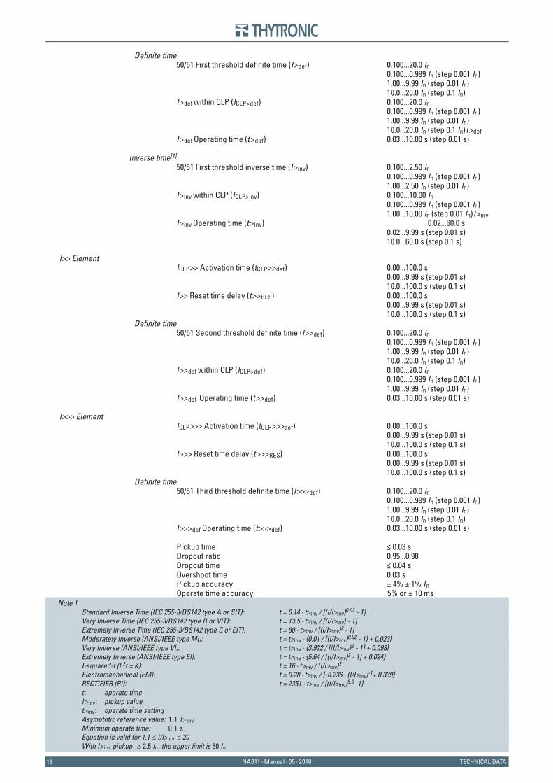
Defi nite time50/51 First threshold defi nite time (I>def) 0.100...20.0 In 0.100...0.999 In (step 0.001 In) 1.00...9.99 In (step 0.01 In) 10.0...20.0 In (step 0.1 In)I>def within CLP (ICLP>def) 0.100...20.0 In 0.100...0.999 In (step 0.001 In) 1.00...9.99 In (step 0.01 In) 10.0...20.0 In (step 0.1 In)I>def I>def Operating time (t>def) 0.03...10.00 s (step 0.01 s)
Inverse time[1]
50/51 First threshold inverse time (I>inv) 0.100...2.50 In 0.100...0.999 In (step 0.001 In) 1.00...2.50 In (step 0.01 In)I>inv within CLP (ICLP>inv) 0.100...10.00 In 0.100...0.999 In (step 0.001 In) 1.00...10.00 In (step 0.01 In)I>inv I>inv Operating time (t>inv) 0.02...60.0 s 0.02...9.99 s (step 0.01 s) 10.0...60.0 s (step 0.1 s)
I>> ElementICLP>> Activation time (tCLP>>def) 0.00...100.0 s 0.00...9.99 s (step 0.01 s) 10.0...100.0 s (step 0.1 s)I>> Reset time delay (t>>RES) 0.00...100.0 s 0.00...9.99 s (step 0.01 s) 10.0...100.0 s (step 0.1 s)
Defi nite time50/51 Second threshold defi nite time (I>>def) 0.100...20.0 In 0.100...0.999 In (step 0.001 In) 1.00...9.99 In (step 0.01 In) 10.0...20.0 In (step 0.1 In)I>>def within CLP (ICLP>def) 0.100...20.0 In 0.100...0.999 In (step 0.001 In) 1.00...9.99 In (step 0.01 In)I>>def Operating time (t>>def) 0.03...10.00 s (step 0.01 s)
I>>> ElementICLP>>> Activation time (tCLP>>>def) 0.00...100.0 s 0.00...9.99 s (step 0.01 s) 10.0...100.0 s (step 0.1 s)I>>> Reset time delay (t>>>RES) 0.00...100.0 s 0.00...9.99 s (step 0.01 s) 10.0...100.0 s (step 0.1 s)
Defi nite time50/51 Third threshold defi nite time (I>>>def) 0.100...20.0 In 0.100...0.999 In (step 0.001 In) 1.00...9.99 In (step 0.01 In) 10.0...20.0 In (step 0.1 In)I>>>def Operating time (t>>>def) 0.03...10.00 s (step 0.01 s)
Pickup time ≤ 0.03 sDropout ratio 0.95...0.98Dropout time ≤ 0.04 sOvershoot time 0.03 sPickup accuracy ± 4% ± 1% InOperate time accuracy 5% or ± 10 ms
Note 1 Standard Inverse Time (IEC 255-3/BS142 type A or SIT): t = 0.14 · t>inv / [(I/I>inv)0.02 - 1] Very Inverse Time (IEC 255-3/BS142 type B or VIT): t = 13.5 · t>inv / [(I/I>inv) - 1] Extremely Inverse Time (IEC 255-3/BS142 type C or EIT): t = 80 · t>inv / [(I/I>inv)2 - 1] Moderately Inverse (ANSI/IEEE type MI): t = t>inv · {0.01 / [(I/I>inv)0.02 - 1] + 0.023} Very Inverse (ANSI/IEEE type VI): t = t>inv · {3.922 / [(I/I>inv)2 - 1] + 0.098} Extremely Inverse (ANSI/IEEE type EI): t = t>inv · {5.64 / [(I/I>inv)2 - 1] + 0.024} I-squared-t (I 2t = K): t = 16 · t>inv / (I/I>inv)2
Electromechanical (EM): t = 0.28 · t>inv / [-0.236 · (I/I>inv)-1+ 0.339] RECTIFIER (RI): t = 2351 · t>inv / [(I/I>inv)5.6- 1] t : operate time I> inv: pickup value t>inv: operate time setting Asymptotic reference value: 1.1 I>inv Minimum operate time: 0.1 s Equation is valid for 1.1 ≤ I/I>inv ≤ 20 With I> inv pickup ≥ 2.5 In, the upper limit is 50 In
17NA011 - Manual - 05 - 2010TECHNICAL DATA
Residual overcurrent - 50N/51NIE> Element
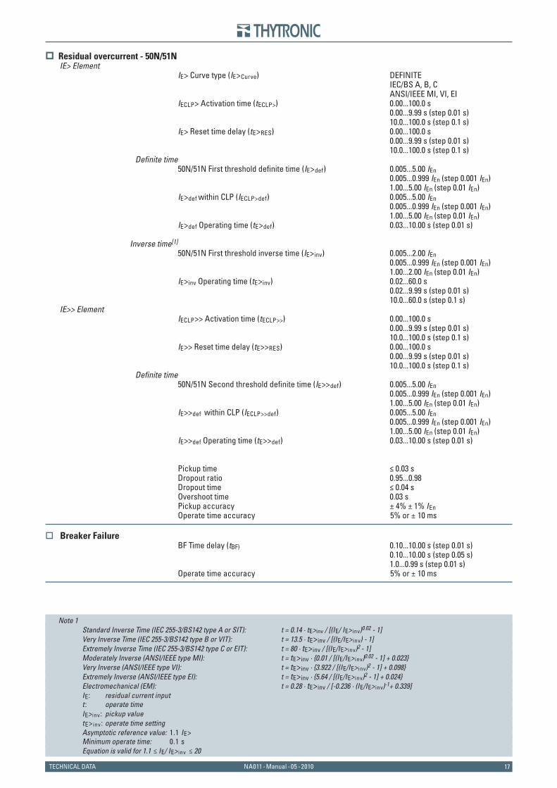
IE> Curve type (IE>Curve) DEFINITE IEC/BS A, B, C ANSI/IEEE MI, VI, EIIECLP> Activation time (tECLP>) 0.00...100.0 s 0.00...9.99 s (step 0.01 s) 10.0...100.0 s (step 0.1 s)IE> Reset time delay (tE>RES) 0.00...100.0 s 0.00...9.99 s (step 0.01 s) 10.0...100.0 s (step 0.1 s)
Defi nite time50N/51N First threshold defi nite time (IE>def) 0.005...5.00 IEn 0.005...0.999 IEn (step 0.001 IEn) 1.00...5.00 IEn (step 0.01 IEn)IE>def within CLP (IECLP>def) 0.005...5.00 IEn 0.005...0.999 IEn (step 0.001 IEn) 1.00...5.00 IEn (step 0.01 IEn)IE>def Operating time (tE>def) 0.03...10.00 s (step 0.01 s)
Inverse time[1]
50N/51N First threshold inverse time (IE>inv) 0.005...2.00 IEn 0.005...0.999 IEn (step 0.001 IEn) 1.00...2.00 IEn (step 0.01 IEn)IE>inv Operating time (tE>inv) 0.02...60.0 s 0.02...9.99 s (step 0.01 s) 10.0...60.0 s (step 0.1 s)
IE>> ElementIECLP>> Activation time (tECLP>>) 0.00...100.0 s 0.00...9.99 s (step 0.01 s) 10.0...100.0 s (step 0.1 s)IE>> Reset time delay (tE>>RES) 0.00...100.0 s 0.00...9.99 s (step 0.01 s) 10.0...100.0 s (step 0.1 s)
Defi nite time50N/51N Second threshold defi nite time (IE>>def) 0.005...5.00 IEn 0.005...0.999 IEn (step 0.001 IEn) 1.00...5.00 IEn (step 0.01 IEn)IE>>def within CLP (IECLP>>def) 0.005...5.00 IEn 0.005...0.999 IEn (step 0.001 IEn) 1.00...5.00 IEn (step 0.01 IEn)IE>>def Operating time (tE>>def) 0.03...10.00 s (step 0.01 s)
Pickup time ≤ 0.03 sDropout ratio 0.95...0.98Dropout time ≤ 0.04 sOvershoot time 0.03 sPickup accuracy ± 4% ± 1% IEnOperate time accuracy 5% or ± 10 ms
Breaker FailureBF Time delay (tBF) 0.10...10.00 s (step 0.01 s) 0.10...10.00 s (step 0.05 s) 1.0...0.99 s (step 0.01 s)Operate time accuracy 5% or ± 10 ms
Note 1 Standard Inverse Time (IEC 255-3/BS142 type A or SIT): t = 0.14 · tE>inv / [(IE/ IE> inv)0.02 - 1] Very Inverse Time (IEC 255-3/BS142 type B or VIT): t = 13.5 · tE>inv / [(IE/IE> inv) - 1] Extremely Inverse Time (IEC 255-3/BS142 type C or EIT): t = 80 · tE>inv / [(IE/IE> inv)2 - 1] Moderately Inverse (ANSI/IEEE type MI): t = tE>inv · {0.01 / [(IE/IE> inv)0.02 - 1] + 0.023} Very Inverse (ANSI/IEEE type VI): t = tE>inv · {3.922 / [(IE/IE> inv)2 - 1] + 0.098} Extremely Inverse (ANSI/IEEE type EI): t = tE>inv · {5.64 / [(IE/IE> inv)2 - 1] + 0.024} Electromechanical (EM): t = 0.28 · tE>inv / [-0.236 · (IE/IE> inv)-1+ 0.339] IE: residual current input t : operate time IE> inv : pickup value tE>inv: operate time setting Asymptotic reference value: 1.1 IE> Minimum operate time: 0.1 s Equation is valid for 1.1 ≤ IE/ IE> inv ≤ 20
1818 NA011 - Manual - 05 - 2010 TECHNICAL DATA
3.8 CONTROL AND MONITORING
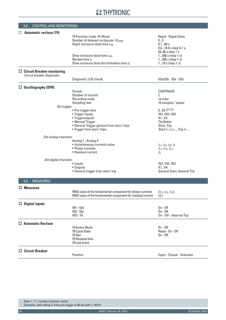
Automatic reclose (79)79 Function mode 79 Mode Rapid - Rapid+SlowNumber of delayed reclosures N .DAR 0...5Rapid reclosure dead time trdt 0.1...60 s 0.0...19.9 s step 0.1 s, 20..60 s step 1 sSlow reclosure dead time tsdt 1...200 s (step 1 s)Reclaim time tr 1...200 s (step 1 s)Slow reclosure fault discrimination time td 1...10 s (step 1 s)
Circuit Breaker monitoringCircuit breaker diagnostic
Diagnostic (CB check) 52a/52b - 52a - 52b
Oscillography (DFR)Format COMTRADENumber of records 2Recording mode circularSampling rate 16 samples / power
Set trigger:Pre-trigger time 0...63 T[1] [2]
Trigger inputs IN1, IN2, IN3Triggeroutputs K1...K4Manual Trigger ThySetterGeneral Trigger general from start / trips Start, TripTrigger from start / trips Start I>, I>>, ...Trip I>...
Set analog channels:Analog 1...Analog 4
Instantaneous currents value iL1, iL2, iL3, iEPhase currents IL1, IL2, IL3Residual current IE
Set digital channels:Inputs IN1, IN2, IN3Outputs K1...K4General trigger from start / trip General Start, General Trip
3.9 MEASURES
MeasuresRMS value of the fundamental component for phase currents (IL1, IL2, IL3)RMS value of the fundamental component for residual current (IE)
Digital inputsIN1 - 52b On - OffIN2 - 52a On - OffIN3 - 79 On - Off - external Trip
Automatic Reclose79 Active Mode On - Off79 Cycle State Reset - On - Off79 Run On - Off79 Residual time 79 Last event
Circuit BreakerPosition Open - Closed - Unknown
Note 1 - T = number of power cyclesExampile, with setting T=4 the pre-trigger is 80 ms with f = 50 Hz
••••••
•••
•••
19NA011 - Manual - 05 - 2010FUNCTION CHARACTERISTICS
4 F U N C T I O N C H A R A C T E R I S T I C S4 F U N C T I O N C H A R A C T E R I S T I C S
4.1 HARDWARE DESCRIPTION
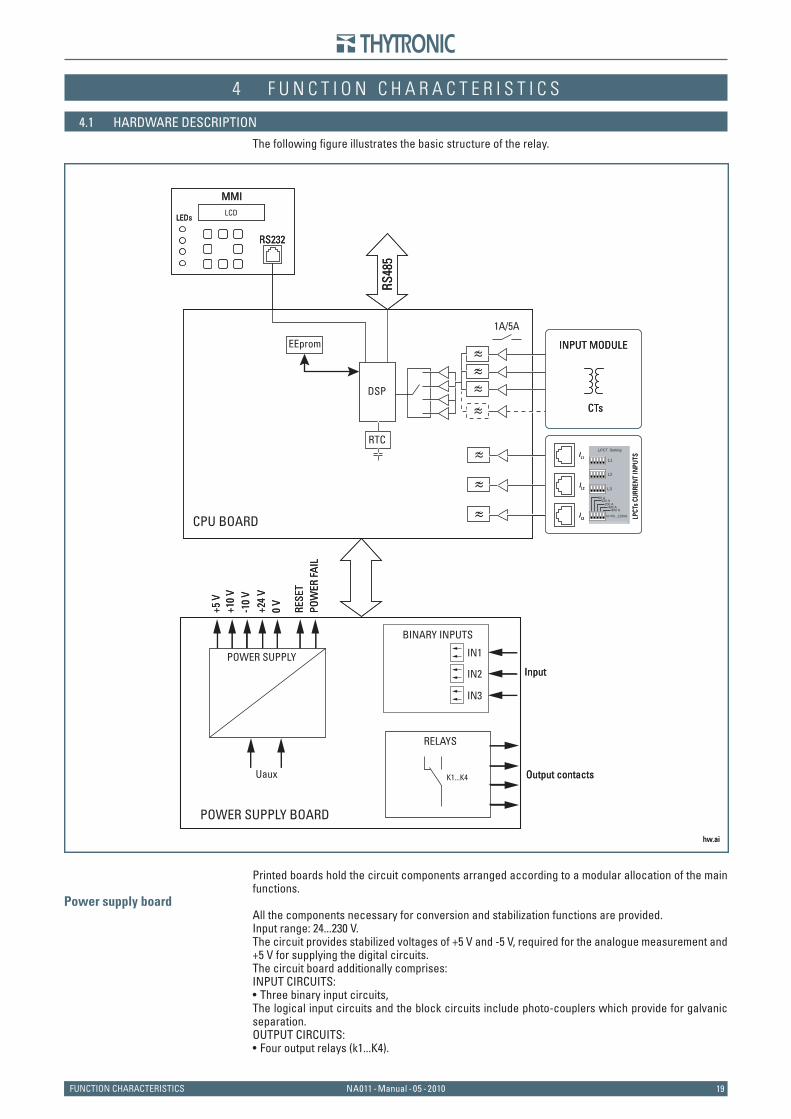
The following fi gure illustrates the basic structure of the relay.
Printed boards hold the circuit components arranged according to a modular allocation of the main functions.
Power supply boardAll the components necessary for conversion and stabilization functions are provided.Input range: 24...230 V. The circuit provides stabilized voltages of +5 V and -5 V, required for the analogue measurement and +5 V for supplying the digital circuits. The circuit board additionally comprises:INPUT CIRCUITS:
Three binary input circuits, The logical input circuits and the block circuits include photo-couplers which provide for galvanic separation. OUTPUT CIRCUITS:
Four output relays (k1...K4).
•
•
hw.ai
RTC
CPU BOARD
POWER SUPPLY BOARD
INPUT MODULE
CTs
DSP
1A/5A
≈≈≈≈
EEprom
RS48
5
RELAYS
K1...K4 Output contacts
RS232
MMILCD
LEDs
BINARY INPUTS
IN1
InputIN2
IN3
POWER SUPPLY
+5 V
+10
V
0 V
+24
V-1
0 V
POW
ER F
AIL
RESE
T
Uaux
≈≈≈ L
PCTs
CUR
REN
T IN
PUTSIL1
IL2
IL3
L1
L2
SettingLPCT
800 A400 A
200 A100 A
50 A
L3
In=50...1250A
2020 NA011 - Manual - 05 - 2010 FUNCTION CHARACTERISTICS
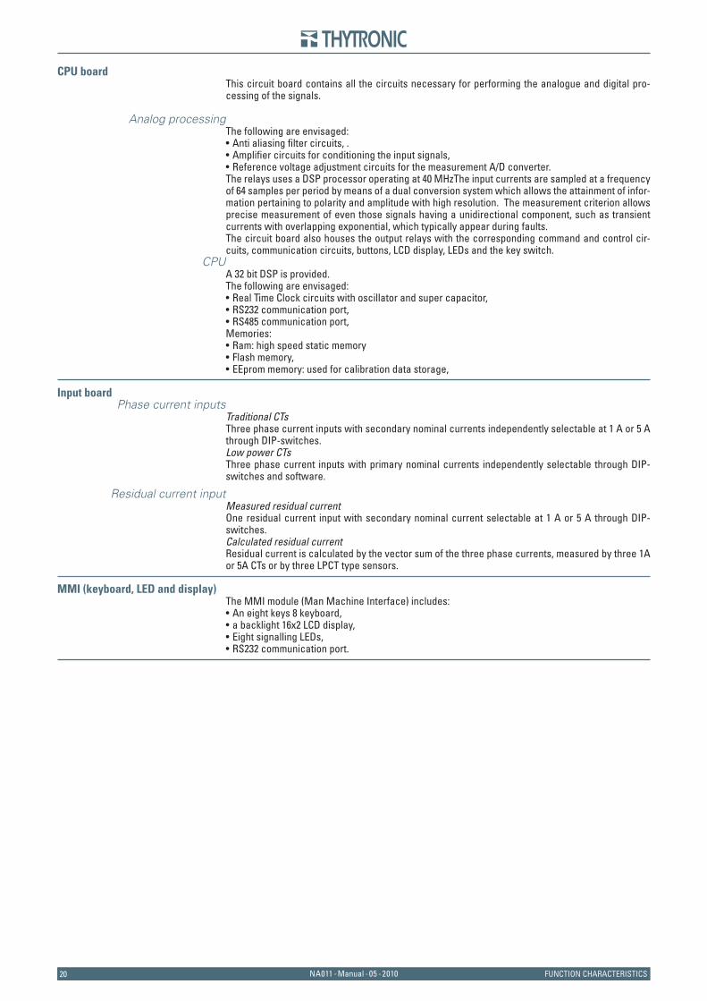
CPU boardThis circuit board contains all the circuits necessary for performing the analogue and digital pro-cessing of the signals.
Analog processingThe following are envisaged:
Anti aliasing fi lter circuits, .Amplifi er circuits for conditioning the input signals, Reference voltage adjustment circuits for the measurement A/D converter.
The relays uses a DSP processor operating at 40 MHzThe input currents are sampled at a frequency of 64 samples per period by means of a dual conversion system which allows the attainment of infor-mation pertaining to polarity and amplitude with high resolution. The measurement criterion allows precise measurement of even those signals having a unidirectional component, such as transient currents with overlapping exponential, which typically appear during faults. The circuit board also houses the output relays with the corresponding command and control cir-cuits, communication circuits, buttons, LCD display, LEDs and the key switch.
CPUA 32 bit DSP is provided. The following are envisaged:
Real Time Clock circuits with oscillator and super capacitor,RS232 communication port,RS485 communication port,
Memories:Ram: high speed static memoryFlash memory,EEprom memory: used for calibration data storage,
Input boardPhase current inputs
Traditional CTsThree phase current inputs with secondary nominal currents independently selectable at 1 A or 5 A through DIP-switches.Low power CTsThree phase current inputs with primary nominal currents independently selectable through DIP-switches and software.
Residual current inputMeasured residual currentOne residual current input with secondary nominal current selectable at 1 A or 5 A through DIP-switches.Calculated residual currentResidual current is calculated by the vector sum of the three phase currents, measured by three 1A or 5A CTs or by three LPCT type sensors.
MMI (keyboard, LED and display)The MMI module (Man Machine Interface) includes:
An eight keys 8 keyboard,a backlight 16x2 LCD display,Eight signalling LEDs,RS232 communication port.
•••
•••
•••
••••
21NA011 - Manual - 05 - 2010FUNCTION CHARACTERISTICS
4.2 SOFTWARE DESCRIPTION
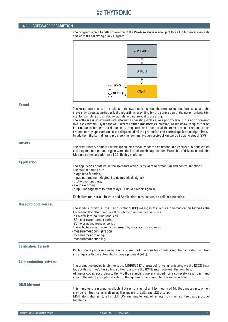
The program which handles operation of the Pro-N relays is made up of three fundamental elements shown in the following block diagram.
KernelThe kernel represents the nucleus of the system: it includes the processing functions closest to the electronic circuits; particularly the algorithms providing for the generation of the synchronisms (tim-ers) for sampling the analogue signals and numerical processing. The software is structured with interrupts operating with various priority levels in a non “pre-emp-tive” task system. By means of Discrete Fourier Transform calculation, based on 64 samples/period, information is deduced in relation to the amplitude and phase of all the current measurements; these are constantly updated and at the disposal of all the protection and control application algorithms. In addition, the kernel manages a service communication protocol known as Basic Protocol (BP).
DriversThe driver library contains all the specialised modules for the command and control functions which make up the connection ring between the kernel and the application. Examples of drivers include the Modbus communication and LCD display modules.
ApplicationThe application contains all the elements which carry out the protection and control functions. The main modules are:
- diagnostic function,- input management (logical inputs and block signal), - protective functions, - event recording, - output management (output relays, LEDs and block signals).
Each element (Kernel, Drivers and Application) may, in turn, be split into modules:
Base protocol (kernel)The module known as the Basic Protocol (BP) manages the service communication between the kernel and the other modules through the communication buses:
- direct for internal functional call,- SPI over synchronous serial, - SCI over asynchronous serial. The activities which may be performed by means of BP include:
- measurement confi guration ,- measurement reading,- measurement enabling.
Calibration (kernel)Calibration is performed using the base protocol functions for coordinating the calibration and test-ing stages with the automatic testing equipment (ATE).
Communication (drivers)The protective device implements the MODBUS RTU protocol for communicating via the RS232 inter-face with the ThySetter setting software and via the RS485 interface with the fi eld bus. All major codes according to the Modbus standard are envisaged; for a complete description and map of the addresses, please refer to the appendix mentioned further in this manual.
MMI (drivers)This handles the menus, available both on the panel and by means of Modbus messages, which may be run from commands using the keyboard, LEDs and LCD display. MMI information is stored in EEPROM and may be loaded remotely by means of the basic protocol functions.
APPLICATION
DRIVERS
timers
KERNELsampling
APPLICATION
DRIVERS
timers
KERNELsampling
2222 NA011 - Manual - 05 - 2010 FUNCTION CHARACTERISTICS
Data Base (application/drivers)Using modular criteria, the database is structured in three sections:
- RAM containing the volatile data, - REE and PAR containing the data recorded in non-volatile memory. Duplication of the data into two memory banks is envisaged with a continuous control system based on the cross checking of the consistency of the stored data. Modification of the calibration pa-rameters is split into two stages; in particular, data undergoing modification is placed in temporary memory and subsequently confirmed permanently (Store command) or discarded (Clear command). Instead, the area identified as REE is set aside for recording data which does not require the Store command for storage, or date written directly by the application (e.g.: counters,...)
Self-test (application)This function cyclically monitors the operation of the main hardware and software functions without affecting the process cycle with any signifi cant delays. In particular, the functions monitored are the following,
- the reference voltage levels,- output relay coil continuity, - the program fl ow control by monitoring the execution times and stack area occupancy,- checking the pilot wires (accelerated logic system), - the consistency of the data in the REE and PAR blocks, duplicated in the EEPROM.
Development toolsFor the development of the project, a CASE instrument has been developed, responsible for the opti-mized production of software code for the management of collaboration, the database and the MMI data and the Xml files used for communication. The automatic code generation criteria ensures the quality of the result in terms of the reusability, verifiability and maintainability of the software life cycle.
23NA011 - Manual - 05 - 2010FUNCTION CHARACTERISTICS
4.3 I/O DESCRIPTION
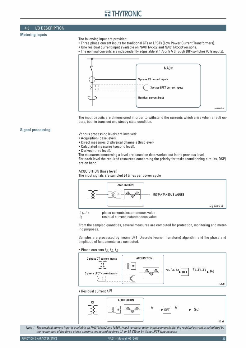
Metering inputsThe following input are provided:
Three phase current inputs for traditional CTs or LPCTs (Low Power Current Transformers).One residual current input available on NA011#xxx2 and NA011#xxx3 versions.The nominal currents are independently adjustable at 1 A or 5 A through DIP-switches (CTs inputs).
The input circuits are dimensioned in order to withstand the currents which arise when a fault oc-curs, both in transient and steady state condition.
Signal processingVarious processing levels are involved:
Acquisition (base level).Direct measures of physical channels (fi rst level).Calculated measures (second level).Derived (third level).
The measures concerning a level are based on data worked out in the previous level.For each level the required resources concerning the priority for tasks (conditioning circuits, DSP) are on hand.
ACQUISITION (base level)The input signals are sampled 24 times per power cycle
- iL1...iL3 phase currents instantaneous value- iE residual current instantaneous value
From the sampled quantities, several measures are computed for protection, monitoring and meter-ing purposes.
Samples are processed by means DFT (Discrete Fourier Transform) algorithm and the phase and amplitude of fundamental are computed:
Phase currents IL1, IL2, IL3
Residual current IE[1]
Note 1 The residual current input is available on NA011#xxx2 and NA011#xxx3 versions; when input is unavailable, the residual current is calculated by the vector sum of the three phase currents, measured by three 1A or 5A CTs or by three LPCT type sensors.
•••
••••
•
•
sensor i .a i
NA011
3 phase CT current inputs
3 phase LPCT current inputs
Residual current input
sensor i .a i
NA011
3 phase CT current inputs
3 phase LPCT current inputs
Residual current input
acquis i t ion.ai
ACQUISITION
INSTANTANEOUS VALUES≈
acquis i t ion.ai
ACQUISITION
INSTANTANEOUS VALUES≈
IL1 .a i
(In)
ACQUISITION
iL1, iL2, iL3DFT
≈IL1, IL2, IL3
3 phase CT current inputs
3 phase LPCT current inputs
IL1 .a i
(In)
ACQUISITION
iL1, iL2, iL3DFT
≈IL1, IL2, IL3
3 phase CT current inputs
3 phase LPCT current inputs
IE .a i
(IEn)
ACQUISITION
iEDFT
CT
≈ IE
IE .a i
(IEn)
ACQUISITION
iEDFT
CT
≈ IE
2424 NA011 - Manual - 05 - 2010 FUNCTION CHARACTERISTICS
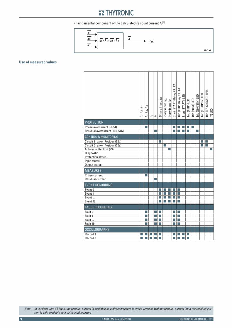
Fundamental component of the calculated residual current IE[1]
Use of measured values
Note 1 In versions with CT input, the residual current is available as a direct measure IE, while versions without residual current input the residual cur-rent is only available as a calculated measure
•
IEC.a i
IL1
IE = IL1 + IL2 + IL3IE
IL3
IL2(I En)
IEC.a i
IL1
IE = IL1 + IL2 + IL3IE
IL3
IL2(I En)
i L1, i
L2, i
L3
I L1, I
L2, I
L3
i E I E Bin
ary
inpu
t IN
1
inar
y in
put I
N2,
inar
y in
put I
N3
Star
t (ST
ART)
Rel
ay K
1...K
4Tr
ip (T
RIP)
Rel
ay K
1...K
4Sr
art (
STAR
T) L
EDTr
ip (T
RIP)
LED
Trip
(50/
51) L
EDTr
ip (5
0N/5
1N) L
EDTr
ip (C
B OP
EN) L
EDTr
ip (C
B CL
OSED
) LED
79
LED
PROTECTIONPhase overcurrent (50/51) g g g g g gResidual overcurrent (50N/51N) g g g g g g
CONTROL & MONITORINGCircuit Breaker Position (52b) g g gCircuit Breaker Position (52a) g g gAutomatic Reclose (79) g gDiagnosticProtection statesInput statesOutput states
MEASURESPhase current gResidual current g
EVENT RECORDINGEvent 0 g g g g gEvent 1 g g g g gEvent ... g g g g gEvent 99 g g g g g
FAULT RECORDINGFault 0 g g g g gFault 1 g g g g gFault ... g g g g gFault 19 g g g g g
OSCILLOGRAPHYRecord 1 g g g g g g g g gRecord 2 g g g g g g g g g
25NA011 - Manual - 05 - 2010FUNCTION CHARACTERISTICS
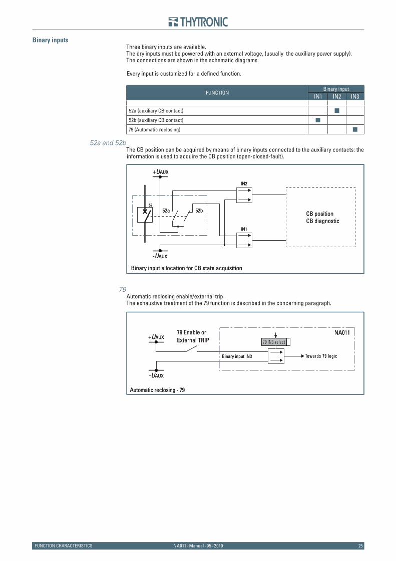
Binary inputsThree binary inputs are available.The dry inputs must be powered with an external voltage, (usually the auxiliary power supply).The connections are shown in the schematic diagrams.
Every input is customized for a defi ned function.
FUNCTIONBinary input
IN1 IN2 IN3
52a (auxiliary CB contact) g
52b (auxiliary CB contact) g
79 (Automatic reclosing) g
52a and 52bThe CB position can be acquired by means of binary inputs connected to the auxiliary contacts: the information is used to acquire the CB position (open-closed-fault).
79Automatic reclosing enable/external trip .The exhaustive treatment of the 79 function is described in the concerning paragraph.
CB positionCB diagnostic
52a52
52b
+UAUX
-UAUX
IN2
IN1
Binary input allocation for CB state acquisition
CB positionCB diagnostic
52a52
52b
+UAUX
-UAUX
IN2
IN1
Binary input allocation for CB state acquisition
79 Enable orExternal TRIP +UAUX
-UAUX
NA011
Binary input IN3 Towards 79 log ic
Automatic reclosing - 79
79 IN3 select
79 Enable orExternal TRIP +UAUX
-UAUX
NA011
Binary input IN3 Towards 79 log ic
Automatic reclosing - 79
79 IN3 select
2626 NA011 - Manual - 05 - 2010 FUNCTION CHARACTERISTICS
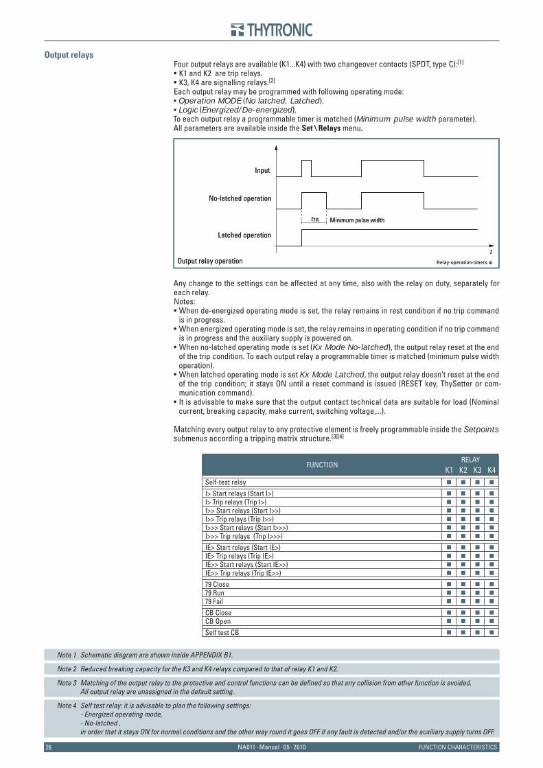
Output relaysFour output relays are available (K1...K4) with two changeover contacts (SPDT, type C):[1]
K1 and K2 are trip relays.K3, K4 are signalling relays.[2]
Each output relay may be programmed with following operating mode:Operation MODE (No latched, Latched).Logic (Energized/De-energized).
To each output relay a programmable timer is matched (Minimum pulse width parameter).All parameters are available inside the Set \ Relays menu.
Any change to the settings can be affected at any time, also with the relay on duty, separately for each relay.Notes:
When de-energized operating mode is set, the relay remains in rest condition if no trip command is in progress.When energized operating mode is set, the relay remains in operating condition if no trip command is in progress and the auxiliary supply is powered on.When no-latched operating mode is set (Kx Mode No-latched), the output relay reset at the end of the trip condition. To each output relay a programmable timer is matched (minimum pulse width operation).When latched operating mode is set Kx Mode Latched, the output relay doesn’t reset at the end of the trip condition; it stays ON until a reset command is issued (RESET key, ThySetter or com-munication command).It is advisable to make sure that the output contact technical data are suitable for load (Nominal current, breaking capacity, make current, switching voltage,...).
Matching every output relay to any protective element is freely programmable inside the Setpoints submenus according a tripping matrix structure.[3][4]
FUNCTIONRELAY
K1 K2 K3 K4Self-test relay g g g g
I> Start relays (Start I>) g g g g
I> Trip relays (Trip I>) g g g g
I>> Start relays (Start I>>) g g g g
I>> Trip relays (Trip I>>) g g g g
I>>> Start relays (Start I>>>) g g g g
I>>> Trip relays (Trip I>>>) g g g g
IE> Start relays (Start IE>) g g g g
IE> Trip relays (Trip IE>) g g g g
IE>> Start relays (Start IE>>) g g g g
IE>> Trip relays (Trip IE>>) g g g g
79 Close g g g g
79 Run g g g g
79 Fail g g g g
CB Close g g g g
CB Open g g g g
Self test CB g g g g
Note 1 Schematic diagram are shown inside APPENDIX B1.
Note 2 Reduced breaking capacity for the K3 and K4 relays compared to that of relay K1 and K2.
Note 3 Matching of the output relay to the protective and control functions can be defi ned so that any collision from other function is avoided. All output relay are unassigned in the default setting.
Note 4 Self test relay: it is advisable to plan the following settings: - Energized operating mode, - No-latched , in order that it stays ON for normal conditions and the other way round it goes OFF if any fault is detected and/or the auxiliary supply turns OFF.
••
••
•
•
•
•
•
Input
No-latched operation
Latched operation
Output relay operation Relay-operat ion-t imers.ai
t
Minimum pulse widthtTR
Input
No-latched operation
Latched operation
Output relay operation Relay-operat ion-t imers.ai
t
Minimum pulse widthtTR
27NA011 - Manual - 05 - 2010FUNCTION CHARACTERISTICS
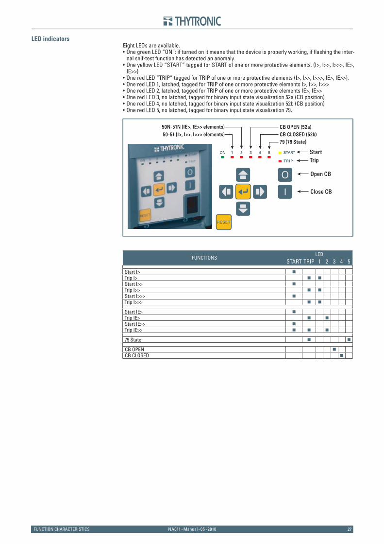
LED indicatorsEight LEDs are available.
One green LED “ON”: if turned on it means that the device is properly working, if fl ashing the inter-nal self-test function has detected an anomaly.One yellow LED “START” tagged for START of one or more protective elements. (I>, I>>, I>>>, IE>, IE>>)One red LED “TRIP” tagged for TRIP of one or more protective elements (I>, I>>, I>>>, IE>, IE>>).One red LED 1, latched, tagged for TRIP of one or more protective elements I>, I>>, I>>>One red LED 2, latched, tagged for TRIP of one or more protective elements IE>, IE>>One red LED 3, no latched, tagged for binary input state visualization 52a (CB position)One red LED 4, no latched, tagged for binary input state visualization 52b (CB position)One red LED 5, no latched, tagged for binary input state visualization 79.
FUNCTIONSLED
START TRIP 1 2 3 4 5
Start I> g
Trip I> g g
Start I>> g
Trip I>> g g
Start I>>> g
Trip I>>> g g
Start IE> g
Trip IE> g g
Start IE>> g
Trip IE>> g g g
79 State g g
CB OPEN g
CB CLOSED g
•
•
••••••
Start
79 (79 State)CB CLOSED (52b)CB OPEN (52a)
50-51 (I>, I>>, I>>> elements)50N-51N (IE>, IE>> elements)
Trip
Open CB
Close CB
Start
79 (79 State)CB CLOSED (52b)CB OPEN (52a)
50-51 (I>, I>>, I>>> elements)50N-51N (IE>, IE>> elements)
Trip
Open CB
Close CB
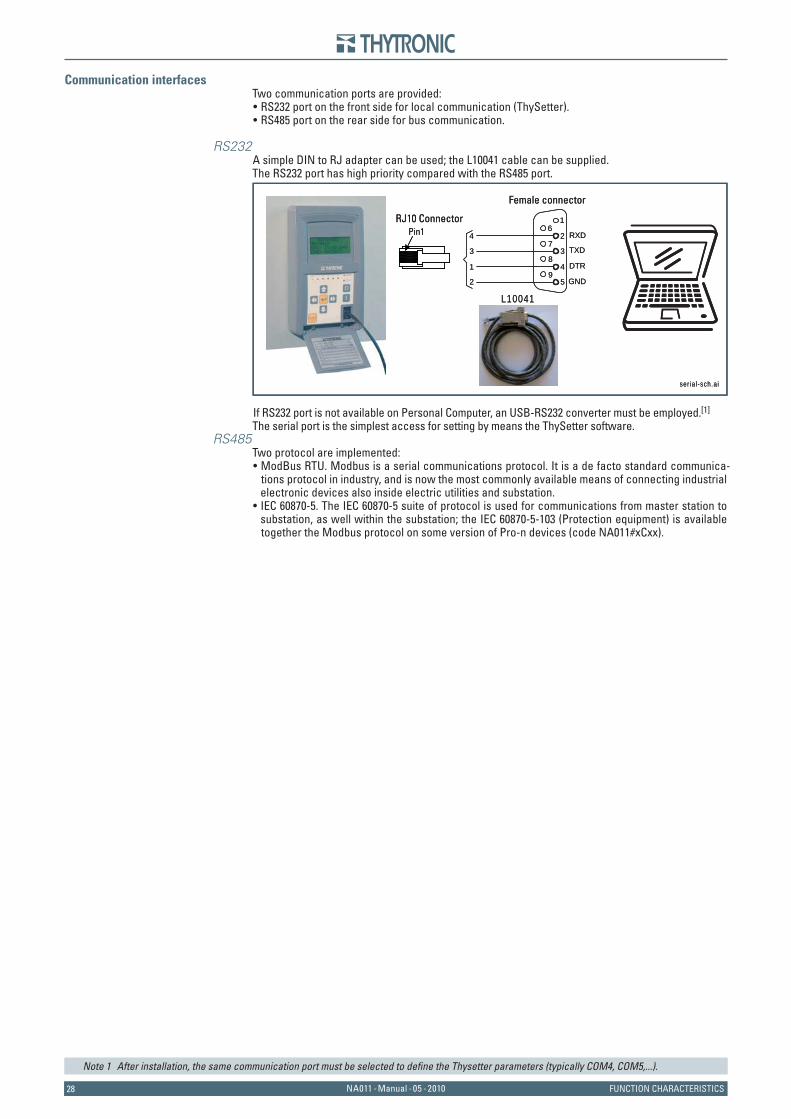
2828 NA011 - Manual - 05 - 2010 FUNCTION CHARACTERISTICS
Communication interfacesTwo communication ports are provided:
RS232 port on the front side for local communication (ThySetter).RS485 port on the rear side for bus communication.
RS232A simple DIN to RJ adapter can be used; the L10041 cable can be supplied.The RS232 port has high priority compared with the RS485 port.
If RS232 port is not available on Personal Computer, an USB-RS232 converter must be employed.[1]
The serial port is the simplest access for setting by means the ThySetter software.RS485
Two protocol are implemented:ModBus RTU. Modbus is a serial communications protocol. It is a de facto standard communica-tions protocol in industry, and is now the most commonly available means of connecting industrial electronic devices also inside electric utilities and substation. IEC 60870-5. The IEC 60870-5 suite of protocol is used for communications from master station to substation, as well within the substation; the IEC 60870-5-103 (Protection equipment) is available together the Modbus protocol on some version of Pro-n devices (code NA011#xCxx).
Note 1 After installation, the same communication port must be selected to defi ne the Thysetter parameters (typically COM4, COM5,...).
••
•
•
ser ia l -sch.ai
L10041
TXD
RXD
DTR
GND
4
3
1
2
1
2
3
4
6
7
8
95
Female connector
RJ10 Connector Pin1
ser ia l -sch.ai
L10041
TXD
RXD
DTR
GND
4
3
1
2
1
2
3
4
6
7
8
95
Female connector
RJ10 Connector Pin1

29NA011 - Manual - 05 - 2010FUNCTION CHARACTERISTICS
4.4 PROTECTIVE ELEMENTS
Traditional CT inputsRelay phase nominal current InThis nominal value must be set by means dip-switch to 1 A or 5 A, same as the secondary CTs nominal current.Dip-switches are located on the CPU board; the exhaustive treatment of Dip setup is described in the “6.4 SETTING NOMINAL CURRENTS In AND IEn” paragraph.
Relay residual nominal current IEnFor NA011#xxx2 versions, the rated value must be set by means dip-switch to 1 A or 5 A, same as the secondary nominal current of the residual CT. Dip-switch is located on the CPU board; the exhaustive treatment of Dip setup is described in the
“6.4 SETTING NOMINAL CURRENTS In AND IEn” paragraph.For NA011#xxx0 versions, the rated value is automatically set to the phase nominal current.[1]
Low Power CT inputsRelay phase nominal current InThis nominal value must be set by means dip-switch to 50 A to 1250 A, same as the primary nominal current of the protected plant. All settings of the current thresholds are referred to the rated cur-rent of the relay In, that corresponds to the primary value automatically set as just described.Dip-switches are located on the rear board; the exhaustive treatment of Dip setup is described in the “6.5 NOMINAL CURRENT In SETTING FOR LPCT” paragraph.
Relay residual nominal current IEnFor NA011#xxx3 versions, the rated value must be set by means dip-switch to 1 A or 5 A, same as the secondary nominal current of the residual CT. Dip-switch is located on board of the CPU board; the exhaustive treatment of Dip setup is de-scribed in the “6.4 and 6.5 SETTING NOMINAL CURRENTS In AND IEn” paragraph.For NA011#xxx1 versions, the rated value is automatically set to the phase nominal current.[1]
SettingsInside the Set \ Base menu the following parameters can be set:
Primary rated values (phase and residual), employed for measures relative to primary values.Measurements reading mode (Reading Direct or Relative).
Phase CT primary current InpThis parameter affects the measure of the phase currents when the primary measurement reading mode is selected (Reading Direct). It must be programmed to the same value of the phase CT primary nominal current Traditional CTs) or to the value set for the LPCT inputs.
Example
The phase CT primary current Inp must be set as: Inp = 500 A
Residual CT primary current IEnpThis parameter affects the measure of the residual current when the primary measurement read-ing mode is selected with traditional CTs inputs. It must be programmed to the same value of the residual CTs primary nominal current.
Example 1
The residual CT primary current IEnp must be set as: IEnp = 100 ANote 1 The residual current is calculated by the vector sum of the three phase currents.
•
••
•
•
••
•
••
•
•
Es-In.ai
KCT = 500A/5A=100
52
In
NA011
IL1...IL3
LPC
Ts C
URRE
NT
INPU
TSL1
L2
In = 500 A
In = 500 A
In = 500 A
LPCT Setting
800 A400 A
200 A100 A
50 A
L3
In=50...1250A
1A/5A
Es-In.ai
KCT = 500A/5A=100
52
In
NA011
IL1...IL3
LPC
Ts C
URRE
NT
INPU
TSL1
L2
In = 500 A
In = 500 A
In = 500 A
LPCT Setting
800 A400 A
200 A100 A
50 A
L3
In=50...1250A
1A/5A
Es1-IEn.ai
1x KTA = 100 A /1 A
52
IEn= 1 A
NA011
Es1-IEn.ai
1x KTA = 100 A /1 A
52
IEn= 1 A
NA011
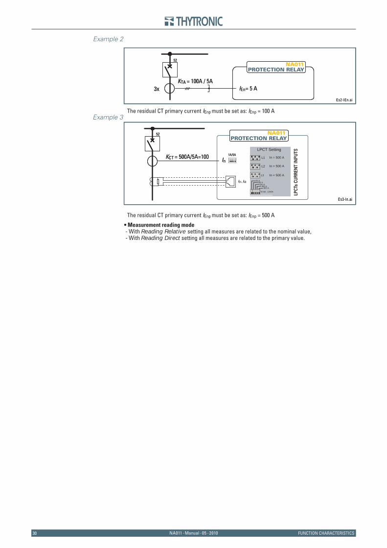
3030 NA011 - Manual - 05 - 2010 FUNCTION CHARACTERISTICS
Example 2
The residual CT primary current IEnp must be set as: IEnp = 100 AExample 3
The residual CT primary current IEnp must be set as: IEnp = 500 A
Measurement reading mode- With Reading Relative setting all measures are related to the nominal value,- With Reading Direct setting all measures are related to the primary value.
•
Es2-IEn.ai
3xKTA = 100A / 5A
52
IEn= 5 A
NA011
Es2-IEn.ai
3xKTA = 100A / 5A
52
IEn= 5 A
NA011
Es3-In.ai
KCT = 500A/5A=100
52
In
NA011
IL1...IL3
LPC
Ts C
URRE
NT
INPU
TS
L1
L2
In = 500 A
In = 500 A
In = 500 A
LPCT Setting
800 A400 A
200 A100 A
50 A
L3
In=50...1250A
1A/5A
Es3-In.ai
KCT = 500A/5A=100
52
In
NA011
IL1...IL3
LPC
Ts C
URRE
NT
INPU
TS
L1
L2
In = 500 A
In = 500 A
In = 500 A
LPCT Setting
800 A400 A
200 A100 A
50 A
L3
In=50...1250A
1A/5A
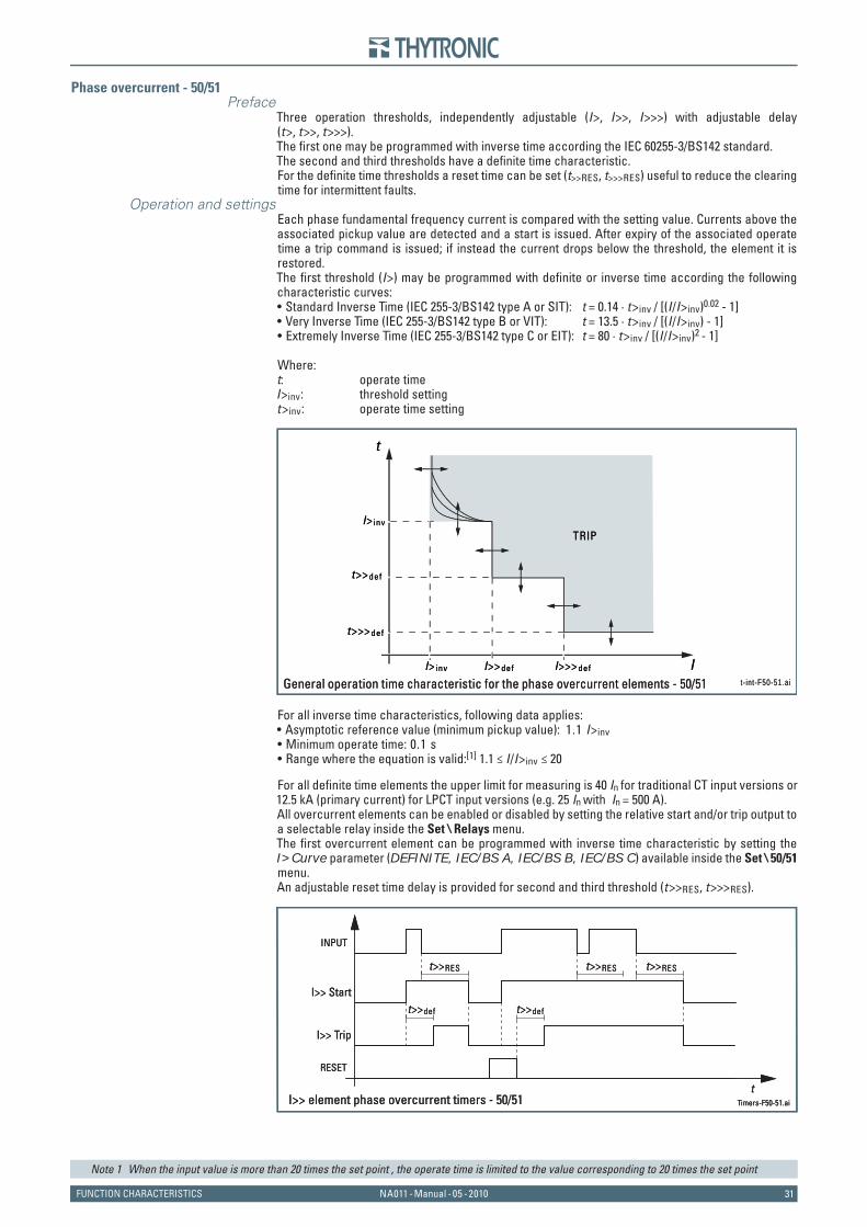
31NA011 - Manual - 05 - 2010FUNCTION CHARACTERISTICS
Phase overcurrent - 50/51Preface
Three operation thresholds, independently adjustable (I>, I>>, I>>>) with adjustable delay (t>, t>>, t>>>).The fi rst one may be programmed with inverse time according the IEC 60255-3/BS142 standard.The second and third thresholds have a defi nite time characteristic.For the defi nite time thresholds a reset time can be set (t>>RES, t>>>RES) useful to reduce the clearing time for intermittent faults.
Operation and settingsEach phase fundamental frequency current is compared with the setting value. Currents above the associated pickup value are detected and a start is issued. After expiry of the associated operate time a trip command is issued; if instead the current drops below the threshold, the element it is restored.The fi rst threshold (I>) may be programmed with defi nite or inverse time according the following characteristic curves:
Standard Inverse Time (IEC 255-3/BS142 type A or SIT): t = 0.14 · t>inv / [(I/I>inv)0.02 - 1]Very Inverse Time (IEC 255-3/BS142 type B or VIT): t = 13.5 · t>inv / [(I/I>inv) - 1]Extremely Inverse Time (IEC 255-3/BS142 type C or EIT): t = 80 · t>inv / [(I/I>inv)2 - 1]
Where:t: operate timeI>inv: threshold settingt>inv: operate time setting
For all inverse time characteristics, following data applies:Asymptotic reference value (minimum pickup value): 1.1 I>invMinimum operate time: 0.1 sRange where the equation is valid:[1] 1.1 ≤ I/I>inv ≤ 20
For all defi nite time elements the upper limit for measuring is 40 In for traditional CT input versions or 12.5 kA (primary current) for LPCT input versions (e.g. 25 In with In = 500 A).All overcurrent elements can be enabled or disabled by setting the relative start and/or trip output to a selectable relay inside the Set \ Relays menu.The fi rst overcurrent element can be programmed with inverse time characteristic by setting the I>Curve parameter (DEFINITE, IEC/BS A, IEC/BS B, IEC/BS C) available inside the Set \ 50/51 menu.An adjustable reset time delay is provided for second and third threshold (t>>RES, t>>>RES).
Note 1 When the input value is more than 20 times the set point , the operate time is limited to the value corresponding to 20 times the set point
•••
•••
t - int-F50-51.ai
II>>def I>>>def
I>inv
t>>>def
t>>def
I>inv
t
General operation time characteristic for the phase overcurrent elements - 50/51
TRIP
t - int-F50-51.ai
II>>def I>>>def
I>inv
t>>>def
t>>def
I>inv
t
General operation time characteristic for the phase overcurrent elements - 50/51
TRIPTRIP
Timers-F50-51.ai
I>> Start
I>> Trip
t>>def t>>def
RESET
INPUT
t>>RES t>>RES t>>RES
tI>> element phase overcurrent timers - 50/51 Timers-F50-51.ai
I>> Start
I>> Trip
t>>def t>>def
RESET
INPUT
t>>RES t>>RES t>>RES
tI>> element phase overcurrent timers - 50/51
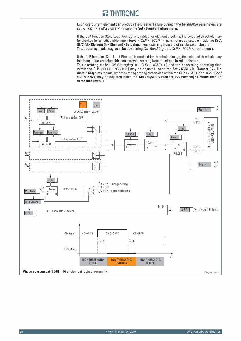
3232 NA011 - Manual - 05 - 2010 FUNCTION CHARACTERISTICS
Each overcurrent element can produce the Breaker Failure output if the BF enable parameters are set to Trip I> and/or Trip I>> inside the Set \ Breaker failure menu.
If the CLP function (Cold Load Pick-up) is enabled for element blocking, the selected threshold may be blocked for an adjustable time interval (tCLP>, tCLP>> parameters adjustable inside the Set \ 50/51 \ I> Element (I>> Element) \ Setpoints menu), starting from the circuit breaker closure.This operating mode may be select by setting On-Blocking the ICLP>, ICLP>> parameters.
If the CLP function (Cold Load Pick-up) is enabled for threshold change, the selected threshold may be changed for an adjustable time interval, starting from the circuit breaker closure.This operating mode (ON-Changing = ICLP>, ICLP>>) and the concerning operating time within the CLP (tCLP>, tCLP>>) may be adjusted inside the Set \ 50/51 \ I> Element (I>> Ele-ment) \ Setpoints menus, whereas the operating thresholds within the CLP ( ICLP>def, ICLP>def, ICLP>>def) may be adjusted inside the Set \ 50/51 \ I> Element (I>> Element) \ Defi nite time (In-verse time) menus.
Fun_50-51S1.ai
I L1
I L2
t >RES
T0
RESET
t >
0T≥1
t >def
I >def I >inv
t >inv
t >RES
Star t I>
Tr ip I>
CB-State
(P ickup wi th in CLP)
(P ickup outs ide CLP)
T 0t CLP>
ICLP>Mode
I C L P >def
t C L P >
I C L P >inv
I L1 ≥ I>
I L1 ≥ I>
BF Enable (ON≡Enable) I>BF
towards BF logic I> BF&Trip I>
TRIP
PING
MAT
RIX
(L
ED+R
ELAY
S)
I> Curve
0T
ABC
A =“1”A =“0 or OFF”
Output t CLP>
I L3
tCLP>
CB State CB OPEN CB CLOSED CB OPEN
Output tCLP>
t
0.1 s
HIGH THRESHOLD/BLOCK
LOW THRESHOLD/UNBLOCK
HIGH THRESHOLD/BLOCK
A = ON - Change settingB = OFFC = ON - Element blocking
I>TR-K I>TR-L
I>ST-L I>ST-K
Phase overcurrent (50/51) - First element logic diagram (I>)
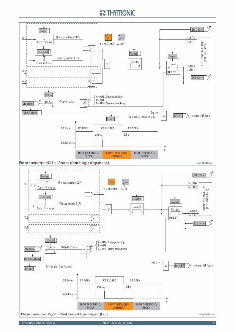
33NA011 - Manual - 05 - 2010FUNCTION CHARACTERISTICS
Fun_50-51S2.ai
I L1
I L2
t >>RES
T0
RESET
t >>def
0T≥1
t >>def
I >>def
t >>RES
Star t I>>
Tr ip I>>
CB-State
(P ickup wi th in CLP)
(P ickup outs ide CLP)
T 0t CLP>>
ICLP>>Mode
I C L P >>def
t C L P >>
I L1 ≥ I>> def
I L1 ≥ I>> def
BF Enable (ON≡Enable) I>>BF
towards BF logic I>> BF&Trip I>>
TRIP
PING
MAT
RIX
(L
ED+R
ELAY
S)
ABC
A =“1”A =“0 or OFF”
Output t CLP>>
I L3
tCLP>>
CB State CB OPEN CB CLOSED CB OPEN
Output tCLP>>
t
0.1 s
HIGH THRESHOLD/BLOCK
LOW THRESHOLD/UNBLOCK
HIGH THRESHOLD/BLOCK
A = ON - Change settingB = OFFC = ON - Element blocking
I>>TR-K I>>TR-L
I>>ST-L I>>ST-K
Phase overcurrent (50/51) - Second element logic diagram (I>>)
Fun_50-51S3.ai
I L1
I L2
t >>>RES
T0
RESET
t >>>def
0T≥1
t >>>def
I >>>def
t >>>RES
Star t I>>
Tr ip I>>>
CB-State
(P ickup wi th in CLP)
(P ickup outs ide CLP)
T 0t CLP>>>
ICLP>>>Mode
I C L P >>def
t C L P >>>
I L1 ≥ I>>> def
I L1 ≥ I>>> def
BF Enable (ON≡Enable) I>>>BF
towards BF logic I>>> BF&Trip I>>>
TRIP
PING
MAT
RIX
(L
ED+R
ELAY
S)
ABC
A =“1”A =“0 or OFF”
Output t CLP>>>
I L3
tCLP>>>
CB State CB OPEN CB CLOSED CB OPEN
Output tCLP>>>
t
0.1 s
HIGH THRESHOLD/BLOCK
LOW THRESHOLD/UNBLOCK
HIGH THRESHOLD/BLOCK
A = ON - Change settingB = OFFC = ON - Element blocking
I>>>TR-K I>>>TR-L
I>>>ST-L I>>>ST-K
Phase overcurrent (50/51) - third element logic diagram (I>>>)
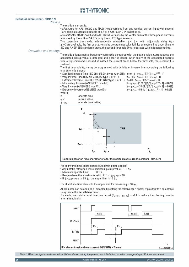
3434 NA011 - Manual - 05 - 2010 FUNCTION CHARACTERISTICS
Residual overcurrent - 50N/51NPreface
The residual current is:Measured for NA011#xxx2 and NA011#xxx3 versions from one residual current input with second-ary nominal current selectable at 1 A or 5 A through DIP-switches or,
Calculated for NA011#xxx0 and NA011#xxx1 versions by the vector sum of the three phase currents, measured by three 1A or 5A CTs or by three LPCT type sensors.Two operation thresholds, independently adjustable (IE>, IE>> with adjustable delay (tE>, tE>>) are available; the fi rst one (IE>) may be programmed with defi nite or inverse time according the IEC and ANSI/IEEE standard curves, the second threshold (IE>>) operates with independent time.
Operation and settingsThe residual fundamental frequency current) is compared with the setting value. Current above the associated pickup value is detected and a start is issued. After expiry of the associated operate time a trip command is issued; if instead the current drops below the threshold, the element it is restored.The fi rst threshold (IE>) may be programmed with defi nite or inverse time according the following characteristic curves:
Standard Inverse Time (IEC 255-3/BS142 type A or SIT): t = 0.14 · tE>inv / [(IE/IE>inv)0.02 - 1]Very Inverse Time (IEC 255-3/BS142 type B or VIT): t = 13.5 · tE>inv / [(IE/IE>inv) - 1]Extremely Inverse Time (IEC 255-3/BS142 type C or EIT): t = 80 · tE>inv / [(IE/IE>inv)2 - 1] Moderately Inverse (ANSI/IEEE type MI): t = tE>inv · {0.01 / [(IE/IE>inv)0.02 - 1] + 0.023}Very Inverse (ANSI/IEEE type VI): t = tE>inv · {3.922 / [(IE/IE>inv)2 - 1] + 0.098}Extremely Inverse (ANSI/IEEE type EI): t = tE>inv · {5.64 / [(IE/IE>inv)2 - 1] + 0.024}
where:t: operate timeIE >: pickup valuetE >inv: operate time setting
For all inverse time characteristics, following data applies:Asymptotic reference value (minimum pickup value): 1.1 IE>Minimum operate time: 0.1 sRange where the equation is valid:[1] 1.1 ≤ IE/IE>inv ≤ 20 If IE>inv pickup ≥ 2.5 IEn, the upper limit is 10 IEn
For all defi nite time elements the upper limit for measuring is 10 IEn.
All elements can be enabled or disabled by setting the relative start and/or trip output to a selectable relay inside the Set \ Relays menu.For each threshold a reset time can be set (tE>RES, tE>>RE) useful to reduce the clearing time for intermittent faults.
Note 1 When the input value is more than 20 times the set point , the operate time is limited to the value corresponding to 20 times the set point
•
••••••
••••
IEIE>>
t E>
t E>>
IE>
t
TRIP
General operation time characteristic for the residual overcurrent elements - 50N/51N
IEIE>>
t E>
t E>>
IE>
t
TRIP
General operation time characteristic for the residual overcurrent elements - 50N/51N
Timers-F50N-51N.ai IE> element residual overcurrent (50N/51N) - Timers
IE> Start
IE> Trip
tE> tE>
RESET
INPUT
tE>RES tE>RES tE>RES
t
Timers-F50N-51N.ai IE> element residual overcurrent (50N/51N) - Timers
IE> Start
IE> Trip
tE> tE>
RESET
INPUT
tE>RES tE>RES tE>RES
t
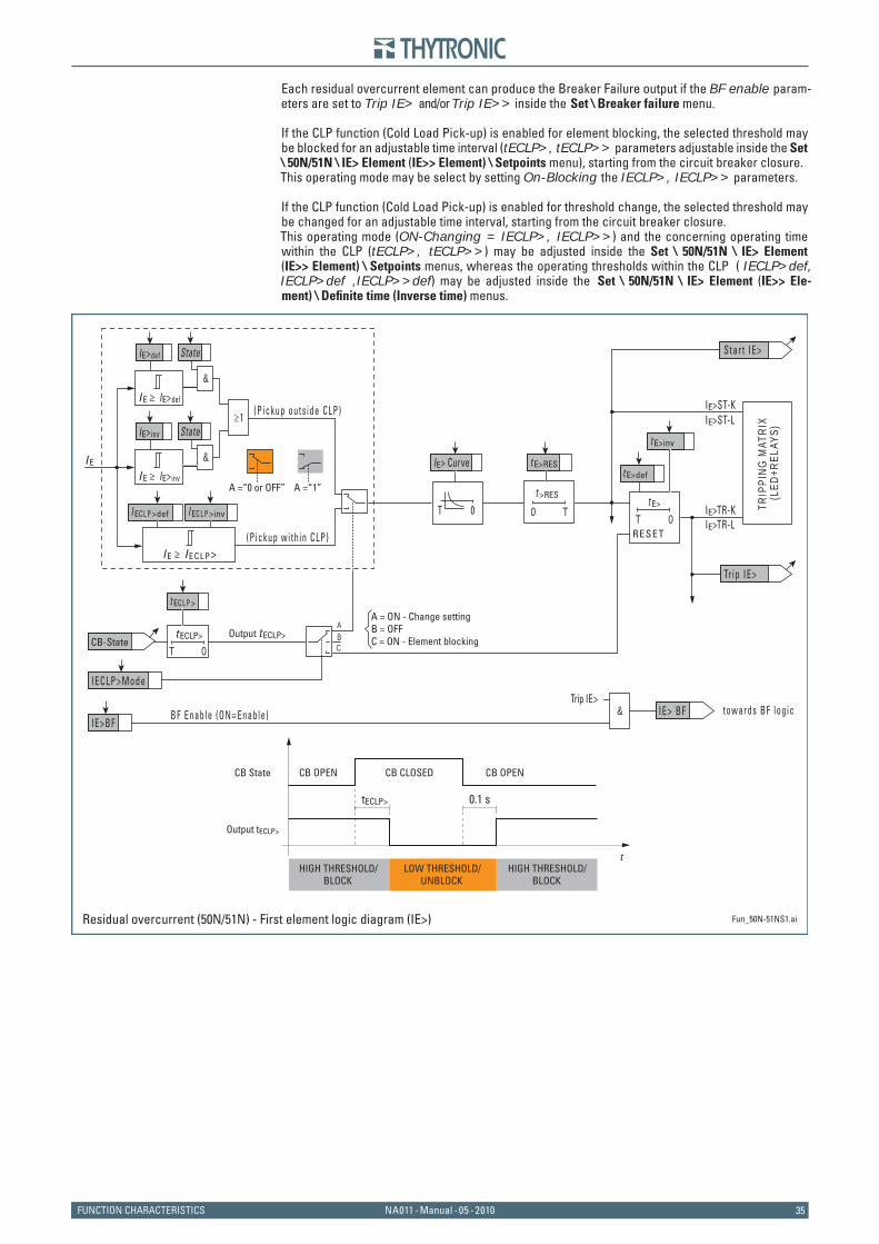
35NA011 - Manual - 05 - 2010FUNCTION CHARACTERISTICS
Each residual overcurrent element can produce the Breaker Failure output if the BF enable param-eters are set to Trip IE> and/or Trip IE>> inside the Set \ Breaker failure menu.
If the CLP function (Cold Load Pick-up) is enabled for element blocking, the selected threshold may be blocked for an adjustable time interval (tECLP>, tECLP>> parameters adjustable inside the Set \ 50N/51N \ IE> Element (IE>> Element) \ Setpoints menu), starting from the circuit breaker closure.This operating mode may be select by setting On-Blocking the IECLP>, IECLP>> parameters.
If the CLP function (Cold Load Pick-up) is enabled for threshold change, the selected threshold may be changed for an adjustable time interval, starting from the circuit breaker closure.This operating mode (ON-Changing = IECLP>, IECLP>>) and the concerning operating time within the CLP (tECLP>, tECLP>>) may be adjusted inside the Set \ 50N/51N \ IE> Element (IE>> Element) \ Setpoints menus, whereas the operating thresholds within the CLP ( IECLP>def, IECLP>def ,IECLP>>def) may be adjusted inside the Set \ 50N/51N \ IE> Element (IE>> Ele-ment) \ Defi nite time (Inverse time) menus.
Fun_50N-51NS1.ai
t >RES
T0
RESET
t E>
0T
t E>def
t E>inv
t E>RES
Star t IE>
Tr ip IE>
CB-StateT 0
t ECLP>
IECLP>Mode
t EC L P >
BF Enable (ON≡Enable) IE>BF
towards BF logic IE> BF&Trip IE>
TRIP
PING
MAT
RIX
(L
ED+R
ELAY
S)
IE> Curve
0T
ABC
A =“1”A =“0 or OFF”
Output t ECLP>
tECLP>
CB State CB OPEN CB CLOSED CB OPEN
Output tECLP>
t
0.1 s
HIGH THRESHOLD/BLOCK
LOW THRESHOLD/UNBLOCK
HIGH THRESHOLD/BLOCK
A = ON - Change settingB = OFFC = ON - Element blocking
IE>TR-K IE>TR-L
IE>ST-L IE>ST-K
Residual overcurrent (50N/51N) - First element logic diagram (IE>)
I E
≥1
(P ickup wi th in CLP)
(P ickup outs ide CLP)
I EC L P >def I EC L P >inv
I E ≥ I ECLP>
&
State
IE>inv
I E ≥ IE>def
I E ≥ IE>inv
IE>def
&
State

3636 NA011 - Manual - 05 - 2010 FUNCTION CHARACTERISTICS
Fun_50N-51NS2.ai
t >RES
T0
RESET
t E>>
0T
t E>>deft E>RES
Star t IE>>
Tr ip IE>>
CB-StateT 0t ECLP>>
IECLP>>Mode
t EC L P >>
BF Enable (ON≡Enable) IE>>BF
towards BF logic IE>> BF&Trip IE>>
TRIP
PING
MAT
RIX
(L
ED+R
ELAY
S)
ABC
A =“1”A =“0 or OFF”
Output t ECLP>>
tECLP>>
CB State CB OPEN CB CLOSED CB OPEN
Output tECLP>>
t
0.1 s
HIGH THRESHOLD/BLOCK
LOW THRESHOLD/UNBLOCK
HIGH THRESHOLD/BLOCK
A = ON - Change settingB = OFFC = ON - Element blocking
IE>>TR-K IE>>TR-L
IE>>ST-L IE>>ST-K
Residual overcurrent (50N/51N) - Second element logic diagram (IE>>)
I E
(P ickup wi th in CLP)
(P ickup outs ide CLP)
I EC L P >>def
I E ≥ I ECLP>>
I E ≥ IE>>def
IE>>def

37NA011 - Manual - 05 - 2010FUNCTION CHARACTERISTICS
Breaker failure - BFPreface
When the protection issues a trip command but, because an anomaly, the circuit breaker cannot open, the breaker failure protection issues a back-up trip command to trip adjacent circuit break-ers.The breaker failure function may be started by internal protective function if associated with BF.
Operation and settingsThe starting of the timer occurs if both the following conditions are fi lled:
Start and trip of internal protective elements (trip of elements matched with BF protection);The CB is closed (the CB state may be acquired by means one or two binary inputs connected to the auxiliary contacts 52a and 52b).
If both conditions are held along the set operate time tBF, the BF element trips at deadline, vice versa the timer is cleared and the function is restored.To the purpose to restore the BF element as quickly as possible, with start of the same protection (see A condition), additionally to the trip of some internal protections, their starts are required (start reset is faster than trip reset).
The element may be enabled or disabled by setting OFF, Trip I>, trip I>>, trip IE> or trip IE>> the BF Enable parameter.
The tBF and BF Enable parameters are available inside the Set \ Breaker failure-BF menu.
BF start from Circuit breakerOne or two binary inputs are designed for acquire the 52a and 52b auxiliary contacts. The CB check parameter is available inside the Set \ Circuit breaker menu, the 52a, 52b and 52a/52b function is assigned to the selected binary inputs.
A)B)
all-FBF.ai General logic diagram of the breaker failure element - BF
5 2 b
5 2 a
Tr i pS t a r t B FTr i p B F
BF Enable t BF
all-FBF.ai General logic diagram of the breaker failure element - BF
5 2 b
5 2 a
Tr i pS t a r t B FTr i p B F
BF Enable t BF
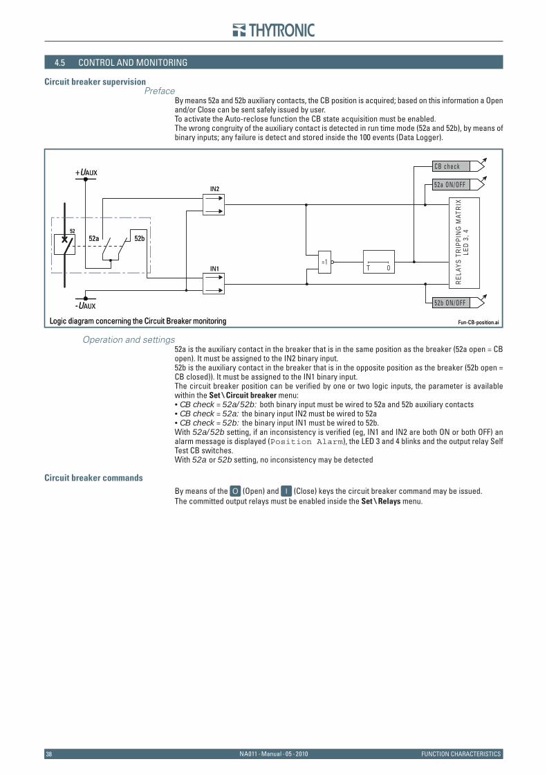
3838 NA011 - Manual - 05 - 2010 FUNCTION CHARACTERISTICS
4.5 CONTROL AND MONITORING
Circuit breaker supervisionPreface
By means 52a and 52b auxiliary contacts, the CB position is acquired; based on this information a Open and/or Close can be sent safely issued by user.To activate the Auto-reclose function the CB state acquisition must be enabled.The wrong congruity of the auxiliary contact is detected in run time mode (52a and 52b), by means of binary inputs; any failure is detect and stored inside the 100 events (Data Logger).
Operation and settings52a is the auxiliary contact in the breaker that is in the same position as the breaker (52a open = CB open). It must be assigned to the IN2 binary input.52b is the auxiliary contact in the breaker that is in the opposite position as the breaker (52b open = CB closed)). It must be assigned to the IN1 binary input.The circuit breaker position can be verifi ed by one or two logic inputs, the parameter is available within the Set \ Circuit breaker menu:CB check = 52a/52b: both binary input must be wired to 52a and 52b auxiliary contactsCB check = 52a: the binary input IN2 must be wired to 52a CB check = 52b: the binary input IN1 must be wired to 52b.
With 52a/52b setting, if an inconsistency is verifi ed (eg, IN1 and IN2 are both ON or both OFF) an alarm message is displayed (Position Alarm), the LED 3 and 4 blinks and the output relay Self Test CB switches.With 52a or 52b setting, no inconsistency may be detected
Circuit breaker commandsBy means of the (Open) and (Close) keys the circuit breaker command may be issued.The committed output relays must be enabled inside the Set \ Relays menu.
•••
Fun-CB-position.ai
RELA
YS T
RIPP
ING
MAT
RIX
LED
3, 4
52a ON/OFF
0T
CB check
52b ON/OFF
52a52
52b
+UAUX
-UAUX
IN2
IN1=1
Logic diagram concerning the Circuit Breaker monitoring Fun-CB-position.ai
RELA
YS T
RIPP
ING
MAT
RIX
LED
3, 4
52a ON/OFF
0T
CB check
52b ON/OFF
52a52
52b
+UAUX
-UAUX
IN2
IN1=1
Logic diagram concerning the Circuit Breaker monitoring
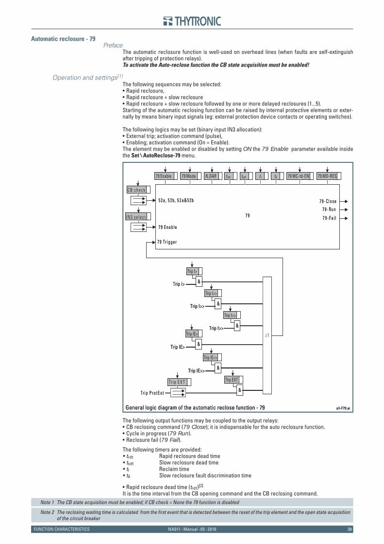
39NA011 - Manual - 05 - 2010FUNCTION CHARACTERISTICS
Automatic reclosure - 79Preface
The automatic reclosure function is well-used on overhead lines (when faults are self-extinguish after tripping of protection relays).To activate the Auto-reclose function the CB state acquisition must be enabled!
Operation and settings[1]
The following sequences may be selected:Rapid reclosure,Rapid reclosure + slow reclosureRapid reclosure + slow reclosure followed by one or more delayed reclosures (1...5).
Starting of the automatic reclosing function can be raised by internal protective elements or exter-nally by means binary input signals (eg: external protection device contacts or operating switches).
The following logics may be set (binary input IN3 allocation):External trip; activation command (pulse),Enabling; activation command (On = Enable).
The element may be enabled or disabled by setting ON the 79 Enable parameter available inside the Set \ AutoReclose-79 menu.
The following output functions may be coupled to the output relays:CB reclosing command (79 Close); it is indispensable for the auto reclosure function.Cycle in progress (79 Run).Reclosure fail (79 Fail).
The following timers are provided:trdt Rapid reclosure dead timetsdt Slow reclosure dead timetr Reclaim timetd Slow reclosure fault discrimination time
Rapid reclosure dead time (trdt)[2]
It is the time interval from the CB opening command and the CB reclosing command.Note 1 The CB state acquisition must be enabled; if CB check = None the 79 function is disabled
Note 2 The reclosing waiting time is calculated from the fi rst event that is detected between the reset of the trip element and the open state acquisition of the circuit breaker
•••
••
•••
••••
•
all-F79.ai
7 9 E n a b l e
5 2 a , 5 2 b , 5 2 a & 5 2 b
7 9 Tr i g g e r
7 9 - C l o s e
7 9 - R u n7 9 7 9 - F a i l
Trip I> &
Trip I>
Trip I>> &
Trip I>>
Trip IE> &
Trip IE>Trip I>> &
Trip I>>
Trip IE>> &
Trip IE>>
Tr i p P r o t E x t &
Trip EXT
≥1
Tr i p E X T
C B c h e c k
I N 3 s e l e c t
79 Enable 79 Mode 79 MC-td-EN 79 MO-RESN.DAR trdt tsdt tr td
General logic diagram of the automatic reclose function - 79 all-F79.ai
7 9 E n a b l e
5 2 a , 5 2 b , 5 2 a & 5 2 b
7 9 Tr i g g e r
7 9 - C l o s e
7 9 - R u n7 9 7 9 - F a i l
Trip I> &
Trip I>
Trip I>> &
Trip I>>
Trip IE> &
Trip IE>Trip I>> &
Trip I>>
Trip IE>> &
Trip IE>>
Tr i p P r o t E x t &
Trip EXT
≥1
Tr i p E X T
C B c h e c k
I N 3 s e l e c t
79 Enable 79 Mode 79 MC-td-EN 79 MO-RESN.DAR trdt tsdt tr td
General logic diagram of the automatic reclose function - 79
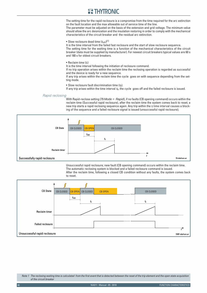
4040 NA011 - Manual - 05 - 2010 FUNCTION CHARACTERISTICS
The setting time for the rapid reclosure is a compromise from the time required for the arc extinction on the fault location and the max allowable out of service time of the line.The parameter must be adjusted on the basis of the extension and grid voltage. The minimum value should allow the arc deionization and the insulation restoring in order to comply with the mechanical characteristics of the circuit breaker and the residual arc extinction.
Slow reclosure dead time (tsdt)[1]
It is the time interval from the failed fast reclosure and the start of slow reclosure sequence.The setting time for the waiting time is a function of the mechanical characteristics of the circuit breaker (data must be supplied by manufacturer). For newest circuit breakers typical values are 60 s and 180 s for oldest circuit breakers.
Reclaim time (tr)It is the time interval following the initiation of reclosure command.If no trip operation arises within the reclaim time the reclosing operation is regarded as successful and the device is ready for a new sequence.If any trip arises within the reclaim time the cycle goes on with sequence depending from the set-ting mode.
Slow reclosure fault discrimination time (td).If any trip arises within the time interval td, the cycle goes off and the failed reclosure is issued.
Rapid reclosingWith Rapid-reclose setting (79 Mode = Rapid), if no faults (CB opening command) occurs within the reclaim time (Successful rapid reclosure), after the reclaim time the system comes back to reset; a new trip starts a rapid reclosing sequence again. Any trip within the tr time interval causes a block-ing of the sequence and a failed reclosure signal is issued (unsuccessful rapid reclosure);
Unsuccessful rapid reclosure; new fault (CB opening command) occurs within the reclaim time.The automatic reclosing system is blocked and a failed reclosure command is issued.After the reclaim time, following a closed CB condition without any faults, the system comes back to reset.
Note 1 The reclosing waiting time is calculated from the fi rst event that is detected between the reset of the trip element and the open state acquisition of the circuit breaker
•
•
•
CB CLOSED CB OPEN CB CLOSED
79-diafram.ai
trdt
CB State
Reclaim timer
t
tr
Successfully rapid reclosure
CB CLOSED CB OPEN CB CLOSED
79-diafram.ai
trdt
CB State
Reclaim timer
t
tr
Successfully rapid reclosure
CB CLOSED CB OPEN CB OPENCB CLOSED
79RF-diafram.ai
trdt
CB State
t
Unsuccessful rapid reclosure
CB CLOSED
Reclaim timer
Failed reclosure
tr tr
CB CLOSED CB OPEN CB OPENCB CLOSED
79RF-diafram.ai
trdt
CB State
t
Unsuccessful rapid reclosure
CB CLOSED
Reclaim timer
Failed reclosure
tr tr

41NA011 - Manual - 05 - 2010FUNCTION CHARACTERISTICS
Rapid +Slow reclosingWith Rapid+Slow reclose setting (79 Mode = Rapid+Slow) if a fault (CB opening command) oc-curs within the reclaim time, after the slow reclosure dead time (tsdt) a slow reclosure is operated. Because no trip occurs within the reclaim time the system comes back to reset; any new trip starts a rapid + slow reclosing sequence again (Successful rapid + slow reclosure).
Conversely if a new fault (CB opening command) occurs within the reclaim time and the next slow reclosure is issued with fault within the slow reclosure fault discrimination time td the automatic reclosing system is blocked and a failed reclosure command is issued (unsuccessful rapid + slow reclosure).
Rapid + slow reclosures and subsequent delayed reclosures
With Rapid+Slow reclose setting (79 Mode = Rapid+Slow) and more than zero reclosures are enabled (79N.DAR = 1...5) if a fault (CB opening command) occurs within the reclaim time, after the slow reclosure dead time (tsdt) a slow reclosure is operated on fault detected later than td1 but within the reclaim time tr; once the reclaim time has elapsed, the delayed reclosing is issued.
CB CLOSED CB OPEN CB OPEN
CB OPEN
CB CLOSED CB CLOSED CB CLOSED
79RLM-diafram.ai
trdt
CB State
t
tsdt
Reclaim timer
Discrimination timer
tr tr tr
td tdFailed reclosure
Rapid reclosure over a fault and subsequent slow and delayed reclosures
CB CLOSED CB OPEN CB OPEN
CB OPEN
CB CLOSED CB CLOSED CB CLOSED
79RLM-diafram.ai
trdt
CB State
t
tsdt
Reclaim timer
Discrimination timer
tr tr tr
td tdFailed reclosure
Rapid reclosure over a fault and subsequent slow and delayed reclosures
CB CLOSEDCB CLOSED CB OPEN CB OPENCB CLOSED
79RL-diafram.ai
trdt
CB State
t
tsdt
Rapid reclosure over a fault and subsequent successfully slow reclosure
tr tr
td
Reclaim timer
Discrimination timer
CB CLOSED
CB CLOSED CB OPEN CB OPEN CB OPENCB CLOSED
79RLF-diafram.ai
trdt
CB State
t
tsdt
tr tr
td
Rapid reclosure over a fault and subsequent slow reclosure still over a fault
Reclaim timer
Discrimination timer
Failed reclosure
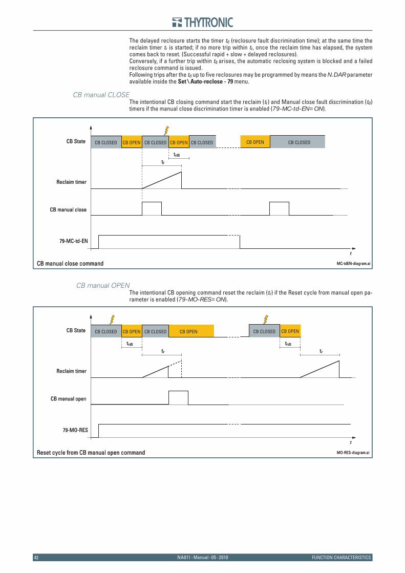
4242 NA011 - Manual - 05 - 2010 FUNCTION CHARACTERISTICS
The delayed reclosure starts the timer td (reclosure fault discrimination time); at the same time the reclaim timer tr is started; if no more trip within tr, once the reclaim time has elapsed, the system comes back to reset. (Successful rapid + slow + delayed reclosures).Conversely, if a further trip within td arises, the automatic reclosing system is blocked and a failed reclosure command is issued.Following trips after the td up to fi ve reclosures may be programmed by means the N.DAR parameter available inside the Set \ Auto-reclose - 79 menu.
CB manual CLOSEThe intentional CB closing command start the reclaim (tr) and Manual close fault discrimination (td) timers if the manual close discrimination timer is enabled (79-MC-td-EN=ON).
CB manual OPENThe intentional CB opening command reset the reclaim (tr) if the Reset cycle from manual open pa-rameter is enabled (79-MO-RES=ON).
CB CLOSED CB OPEN CB OPEN CB OPENCB CLOSED CB CLOSED
MC-tdEN-diagram.ai
trdt
CB State
t
CB manual close command
CB CLOSED
Reclaim timer
CB manual close
79-MC-td-EN
tr
CB CLOSED CB OPEN CB OPEN CB OPENCB CLOSED CB CLOSED
MC-tdEN-diagram.ai
trdt
CB State
t
CB manual close command
CB CLOSED
Reclaim timer
CB manual close
79-MC-td-EN
tr
CB CLOSED CB OPEN CB OPENCB OPENCB CLOSED
MO-RES-diagram.ai
trdt
CB State
t
trdt
Reset cycle from CB manual open command
CB CLOSED
Reclaim timer
CB manual open
79-MO-RES
tr tr
CB CLOSED CB OPEN CB OPENCB OPENCB CLOSED
MO-RES-diagram.ai
trdt
CB State
t
trdt
Reset cycle from CB manual open command
CB CLOSED
Reclaim timer
CB manual open
79-MO-RES
tr tr
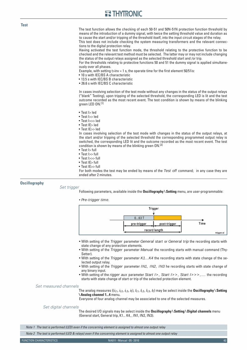
43NA011 - Manual - 05 - 2010FUNCTION CHARACTERISTICS
TestThe test function allows the checking of each 50-51 and 50N-51N protection function threshold by means of the introduction of a dummy signal, with twice the setting threshold value and duration as to cause the start and/or tripping of the threshold itself, into the input circuit stages of the relay. This test does not include checking the system measuring transformers and the relevant connec-tions to the digital protection relay. Having activated the test function mode, the threshold relating to the protective function to be checked and the relevant test method must be selected. The latter may or may not include changing the status of the output relays assigned as the selected threshold start and /or trip. For the thresholds relating to protective functions 50 and 51 the dummy signal is applied simultane-ously over all phases. Example, with setting t>inv = 1 s, the operate time for the fi rst element 50/51is:
10 s with IEC/BS A characteristic13.5 s with IEC/BS B characteristic26.6 s with IEC/BS C characteristic
In cases involving selection of the test mode without any changes in the status of the output relays (“blank” Testing), upon tripping of the selected threshold, the corresponding LED is lit and the test outcome recorded as the most recent event. The test condition is shown by means of the blinking green LED ON.[1]
Test I> ledTest I>> ledTest I>>> ledTest IE> ledTest IE>> led
In cases involving selection of the test mode with changes in the status of the output relays, at the start and/or tripping of the selected threshold the corresponding programmed output relay is switched, the corresponding LED lit and the outcome recorded as the most recent event. The test condition is shown by means of the blinking green ON.[2]
Test I> fullTest I>> fullTest I>>> fullTest IE> fullTest IE>> full
For both modes the test may be ended by means of the Test off command; in any case they are ended after 2 minutes.
Oscillography Set trigger
Following parameters, available inside the Oscillography \ Setting menu, are user-programmable:
Pre-trigger time.
With setting of the Trigger parameter General start or General trip the recording starts with state change of any protection elements.With setting of the Trigger parameter Manual the recording starts with manual command (Thy-Setter).With setting of the Trigger parameter K1...K4 the recording starts with state change of the se-lected output relay.With setting of the Trigger parameter IN1, IN2, IN3 he recording starts with state change of any binary input.With setting of the rigger aux parameter Start I>, Start I>>, Start I>>>,.... the recording starts with state change of start or trip of the selected protection element.
Set measured channels
The analog measures ((iL1, iL2, iL3, iE), IL1, IL2, IL3, IE) may be select inside the Oscillography \ Setting \ Analog channel 1...4 menu.Everyone of four analog channel may be associated to one of the selected measures.
Set digital channelsThe desired I/O signals may be select inside the Oscillography \ Setting \ Digital channels menu(General start, General trip, K1... K4, , IN1, IN2, IN3).
Note 1 The test is performed (LED) even if the concerning element is assigned to almost one output relay
Note 2 The test is performed (LED & relays) even if the concerning element is assigned to almost one output relay
•••
•••••
•••••
•
•
•
•
•
•
trigger.ai
Trigger
Timepre-trigger
record length
post-trigger
0...63 T
trigger.ai
Trigger
Timepre-trigger
record length
post-trigger
0...63 T
4444 NA011 - Manual - 05 - 2010 MEASURES, LOGIC STATES AND COUNTERS
5 M E A S U R E S , L O G I C S T A T E S A N D C O U N T E R S 5 M E A S U R E S , L O G I C S T A T E S A N D C O U N T E R S Measures
RMS value of fundamental component for phase currents (IL1, IL2, IL3)RMS value of fundamental component for measured residual current (IE)
Circuit breaker
The CB and 79 states are providedPosition Open - Closed - Unknown
and the binary inputs state:IN1-52b On/OffIN2-52a On/OffIN3-79 On/Off
CountersFor every protective element and control function several counters are available; the partial coun-ters can be cleared by the user.Every partial counter is reset to zero when ten thousand count is passed. All partial counters can be cleared by means a single command; for this purpose the Reset coun-ters command must be issued available inside the Reset menu.
Counter ST I> (start I> element)Counter ST I>> (start I>> element)Counter ST I>>> (start I>>> element)Counter ST IE> (start IE> element)Counter ST IE>> (start IE>> element)Counter TR I> (trip I> element)Counter TR I>> (trip I>> element)Counter TR I>>> (trip I>>> element)Counter TR IE> (trip IE> element)Counter TR IE>> (trip IE>> element)Counter 79 RR (Rapid reclosures)Counter 79 RL (Slow reclosures)Counter 79 RM (Delayed reclosures)Counter 79 FR P (Failed reclosures)Counter 79 FR E (Failed reclosures)Counter 79 FR X (Failed reclosures)
Fault recording - SFRRecording[1] is triggered by:
Relay activation (OFF-ON)External trigger (binary input) programmed as Fault triggerElement start or trip
Twenty events are recorded into a circular FIFO (First In, First Out) buffer.[2]
Following information are stored in every record:Read \ Faults \ Info menu
Faults stored[3]
Last faultRead \ Faults \ Fault menu
Fault number (F-Number)Fault Cause (F-Cause)Fault Phases (F-Phases)Phase currents (F-IL1, F-IL2, F-IL3)Residual current IEr F-IE)Date and time (F-Year)Date and time (F-Year)Date and time (F-Month)...Date and time (F-Millisecond)
The fault log may be erased by means of the command available inside the Read \ Faults \ Reset menu.
Event recording - EventsRecording is triggered by:
Power up and/or Power down.Element start or trip.Binary input switch (OFF-ON or ON-OFF).Setting modify.Control function trip (CB switch OFF-ON or ON-OFF).
One hundred events are recorded into a circular FIFO (First In, First Out) buffer (Read \ Events \ Info
Note 1 Data concerning the twenty events are stored into non volatile memory; they are held in spite of power down
Note 2 Fault 0 is the newest event, while the Fault 19 is the oldest event
Note 3 Counter is updated at any new record; it may be cleared by means ThySetter
••
•
•••
••••••••••••••••
•••
••
••••••••••
•••••
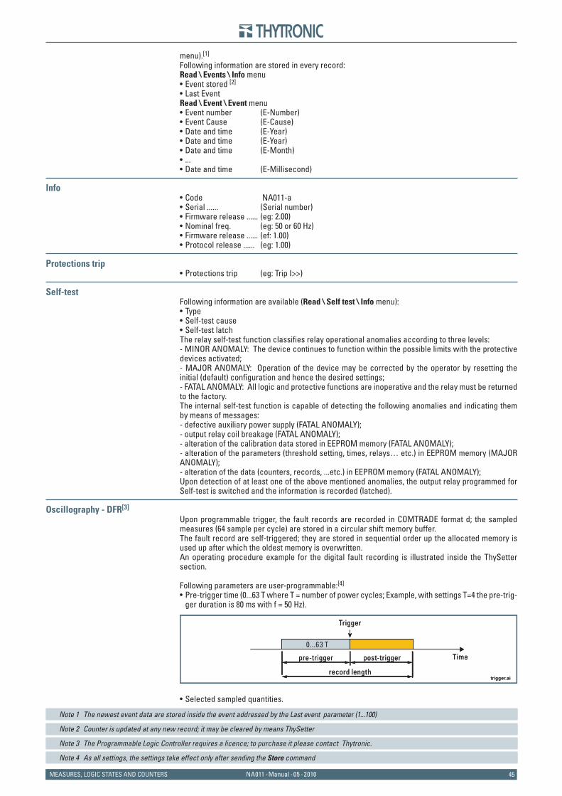
45NA011 - Manual - 05 - 2010MEASURES, LOGIC STATES AND COUNTERS
menu).[1]
Following information are stored in every record:Read \ Events \ Info menu
Event stored [2]
Last EventRead \ Event \ Event menu
Event number (E-Number)Event Cause (E-Cause)Date and time (E-Year)Date and time (E-Year)Date and time (E-Month)...Date and time (E-Millisecond)
InfoCode NA011-aSerial ...... (Serial number)Firmware release ...... (eg: 2.00)Nominal freq. (eg: 50 or 60 Hz)Firmware release ...... (ef: 1.00)Protocol release ...... (eg: 1.00)
Protections tripProtections trip (eg: Trip I>>)
Self-testFollowing information are available (Read \ Self test \ Info menu):
TypeSelf-test causeSelf-test latch
The relay self-test function classifi es relay operational anomalies according to three levels: - MINOR ANOMALY: The device continues to function within the possible limits with the protective devices activated; - MAJOR ANOMALY: Operation of the device may be corrected by the operator by resetting the initial (default) confi guration and hence the desired settings; - FATAL ANOMALY: All logic and protective functions are inoperative and the relay must be returned to the factory. The internal self-test function is capable of detecting the following anomalies and indicating them by means of messages: - defective auxiliary power supply (FATAL ANOMALY); - output relay coil breakage (FATAL ANOMALY); - alteration of the calibration data stored in EEPROM memory (FATAL ANOMALY); - alteration of the parameters (threshold setting, times, relays… etc.) in EEPROM memory (MAJOR ANOMALY); - alteration of the data (counters, records, ...etc.) in EEPROM memory (FATAL ANOMALY);Upon detection of at least one of the above mentioned anomalies, the output relay programmed for Self-test is switched and the information is recorded (latched).
Oscillography - DFR[3]
Upon programmable trigger, the fault records are recorded in COMTRADE format d; the sampled measures (64 sample per cycle) are stored in a circular shift memory buffer. The fault record are self-triggered; they are stored in sequential order up the allocated memory is used up after which the oldest memory is overwritten.An operating procedure example for the digital fault recording is illustrated inside the ThySetter section.
Following parameters are user-programmable:[4]
Pre-trigger time (0...63 T where T = number of power cycles; Example, with settings T=4 the pre-trig-ger duration is 80 ms with f = 50 Hz).
Selected sampled quantities.
Note 1 The newest event data are stored inside the event addressed by the Last event parameter (1...100)
Note 2 Counter is updated at any new record; it may be cleared by means ThySetter
Note 3 The Programmable Logic Controller requires a licence; to purchase it please contact Thytronic.
Note 4 As all settings, the settings take effect only after sending the Store command
••
•••••••
••••••
•
•••
•
•
trigger.ai
Trigger
Timepre-trigger
record length
post-trigger
0...63 T
trigger.ai
Trigger
Timepre-trigger
record length
post-trigger
0...63 T
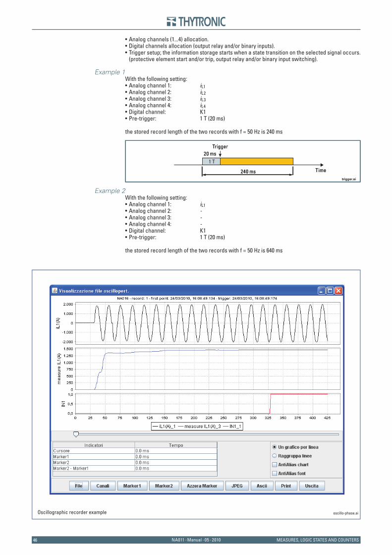
4646 NA011 - Manual - 05 - 2010 MEASURES, LOGIC STATES AND COUNTERS
Analog channels (1...4) allocation.Digital channels allocation (output relay and/or binary inputs).Trigger setup; the information storage starts when a state transition on the selected signal occurs. (protective element start and/or trip, output relay and/or binary input switching).
Example 1With the following setting:
Analog channel 1: iL1Analog channel 2: iL2Analog channel 3: iL3Analog channel 4: iL4Digital channel: K1Pre-trigger: 1 T (20 ms)
the stored record length of the two records with f = 50 Hz is 240 ms
Example 2With the following setting:
Analog channel 1: iL1Analog channel 2: -Analog channel 3: -Analog channel 4: -Digital channel: K1Pre-trigger: 1 T (20 ms)
the stored record length of the two records with f = 50 Hz is 640 ms
•••
••••••
••••••
trigger.ai
Trigger
Time240 ms
1 T20 ms
trigger.ai
Trigger
Time240 ms
1 T20 ms
oscillo-phase.aiOscillographic recorder example

47NA011 - Manual - 05 - 2010INSTALLATION
6 I N S T A L L A T I O N6 I N S T A L L A T I O N
6.1 PACKAGING
Packaging consists of a paperboard packaging guaranteeing adequate protection for transport and storage under normal environmental conditions. The Pro-N protection relays must be stored within the required temperature limits; the relative hu-midity should not cause condensation or formation of frost.It is recommended that the devices are stored in their packaging; in the case of long storage, espe-cially in extreme climatic conditions.It is recommended that the packaging not be disposed of into the environment, but kept in case the relay should be moved at some later time.
6.2 MOUNTING
The devices are housed inside metal cases suitable assembly:Flush mountingRack9”.
Flush mountingThe fi xed case, fi tted with special fastening brackets, is mounted on the front of electric control board, previously drilled as indicated in the drawing.In case of side-by-side mounting of several relays the minimum drilling distance is determined by the front dimensions indicated in the overall dimensions drawing, increased by 3 mm, to ensure an adequate tolerance and gasket space between adjacent relays.The depth dimension, as indicated in the drawing, must be increased by as much as needed to allow room for the wiring.
Remove the upper tile and open the little door to access the fastening screws.
••
•
75 30107
177
ON 41 32 5
TRIP
START
102.5 ±0.3
70
161
154
N.4 fori ø 3.5
101
171
149
F1
D1
RX
TX
F2F3F4F5
A1A2
A3A4A5
A6A7A8
A9A10A11
A12A13A14
A15A16
A17A18
A19A20
A21A22
B1B2B3B4B5B6B7B8
C1 C2
C4C3
C5 C6
C7 C8
E1
75 30107
177
ON 41 32 5
TRIP
START
102.5 ±0.3
70
161
154
N.4 fori ø 3.5
101
171
149
F1
D1
RX
TX
F2F3F4F5
A1A2
A3A4A5
A6A7A8
A9A10A11
A12A13A14
A15A16
A17A18
A19A20
A21A22
B1B2B3B4B5B6B7B8
C1 C2
C4C3
C5 C6
C7 C8
E1
Remove-t i le.aiRemoving tie to access the fastening screws Remove-t i le.aiRemoving tie to access the fastening screws
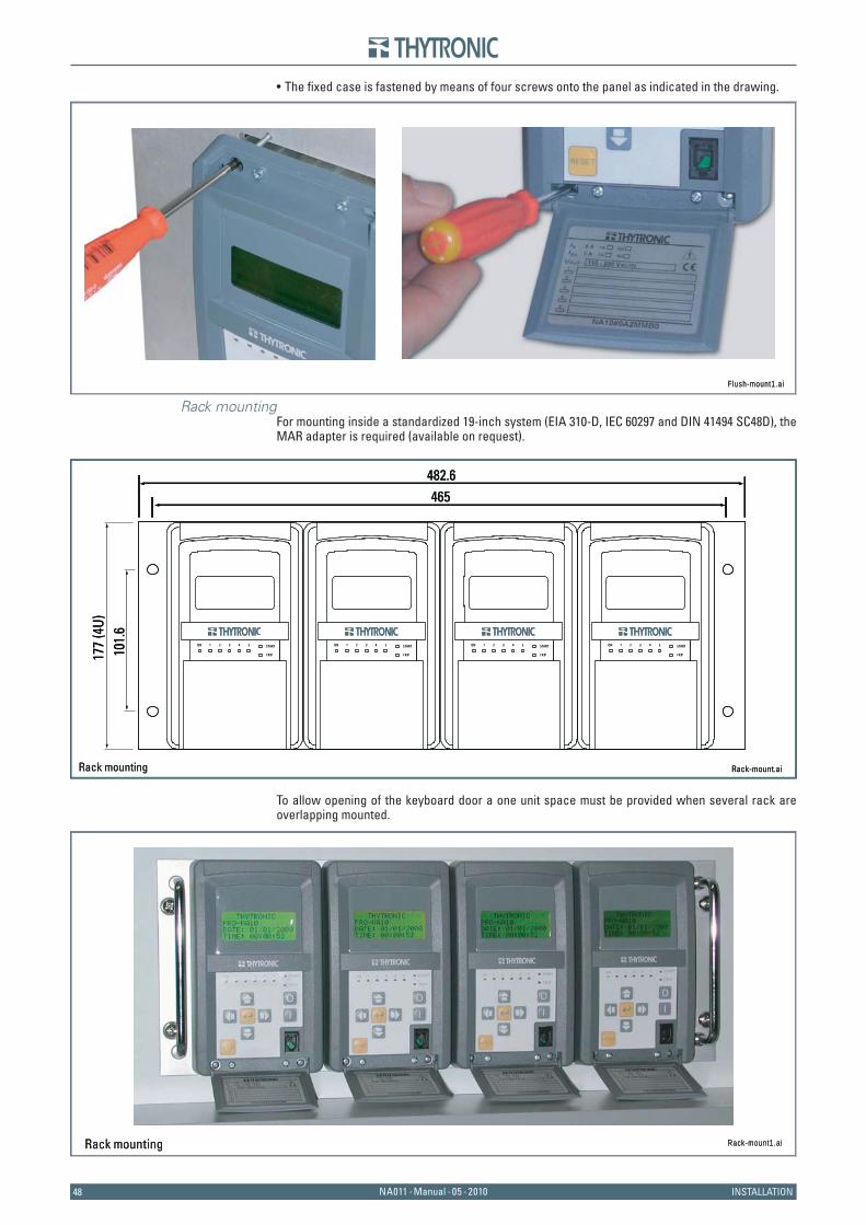
4848 NA011 - Manual - 05 - 2010 INSTALLATION
The fi xed case is fastened by means of four screws onto the panel as indicated in the drawing.
Rack mountingFor mounting inside a standardized 19-inch system (EIA 310-D, IEC 60297 and DIN 41494 SC48D), the MAR adapter is required (available on request).
To allow opening of the keyboard door a one unit space must be provided when several rack are overlapping mounted.
•
Flush-mount1.aiFlush-mount1.ai
Rack-mount.aiRack mounting
177
(4U)
101.
6
482.6465
ON 41 32 5
TRIP
START ON 41 32 5
TRIP
START ON 41 32 5
TRIP
START ON 41 32 5
TRIP
START
Rack-mount.aiRack mounting
177
(4U)
101.
6
482.6465
ON 41 32 5
TRIP
START ON 41 32 5
TRIP
START ON 41 32 5
TRIP
START ON 41 32 5
TRIP
START
Rack-mount1.aiRack mounting Rack-mount1.aiRack mounting
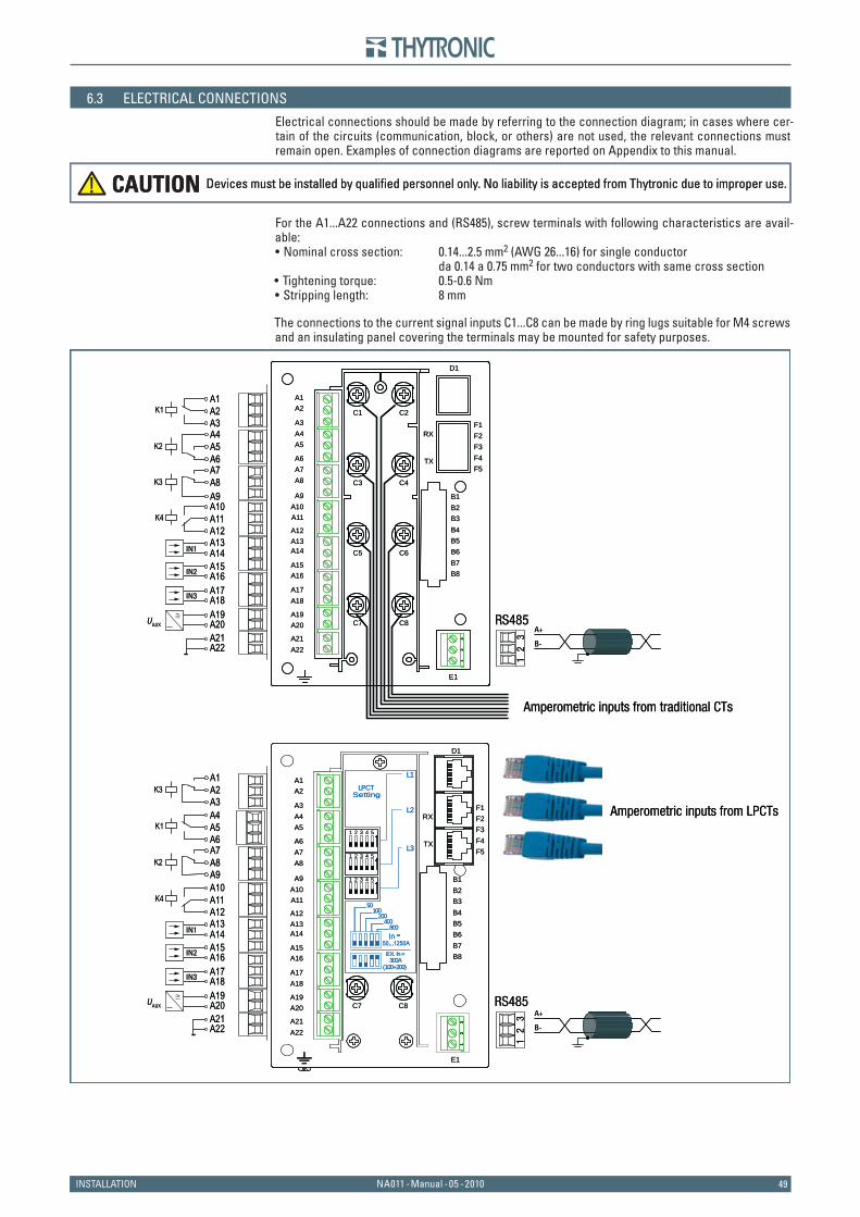
49NA011 - Manual - 05 - 2010INSTALLATION
6.3 ELECTRICAL CONNECTIONS
Electrical connections should be made by referring to the connection diagram; in cases where cer-tain of the circuits (communication, block, or others) are not used, the relevant connections must remain open. Examples of connection diagrams are reported on Appendix to this manual.
For the A1...A22 connections and (RS485), screw terminals with following characteristics are avail-able:
Nominal cross section: 0.14...2.5 mm2 (AWG 26...16) for single conductor da 0.14 a 0.75 mm2 for two conductors with same cross section
Tightening torque: 0.5-0.6 NmStripping length: 8 mm
The connections to the current signal inputs C1...C8 can be made by ring lugs suitable for M4 screws and an insulating panel covering the terminals may be mounted for safety purposes.
•
••
Devices must be installed by qualified personnel only. No liability is accepted from Thytronic due to improper use.CAUTION Devices must be installed by qualified personnel only. No liability is accepted from Thytronic due to improper use.CAUTION
Amperometric inputs from traditional CTs
Amperometric inputs from LPCTs
RS485
12
3
RS485
12
3
B-
A+
B-
A+
UAUX
≅
A4A5K2
A2A1
A3K1
A11A10
A12K4
A13A14
A9
A7A8
A6
K3
A15A16A17A18A19
IN1
A20A21A22
IN2
IN3
F1
D1
RX
TX
F2F3F4F5
A1A2
A3A4A5
A6A7A8
A9A10A11
A12A13A14
A15A16
A17A18
A19A20
A21A22
B1B2B3B4B5B6B7B8
C1 C2
C4C3
C5 C6
C7 C8
E1
31
2
UAUX
≅
A5A4
A6K1
A11A10
A12K4
A13A14
A3
A1A2K3
A9
A7A8K2
A15A16A17A18A19
IN1
A20A21A22
IN2
IN3
C7 C8
F1
D1
RX
TX
F2F3F4F5
A1A2
A3A4A5
A6A7A8
A9A10A11
A12A13A14
A15A16
A17A18
A19A20
A21A22
B1B2B3B4B5B6B7B8
E1
31
2
LPCTSetting
(100+200)300A
EX. In=
50
200400
100
800
L3
L2
L1
1 2 3 4 5
1 2 3 4 5
1 2 3 4 5
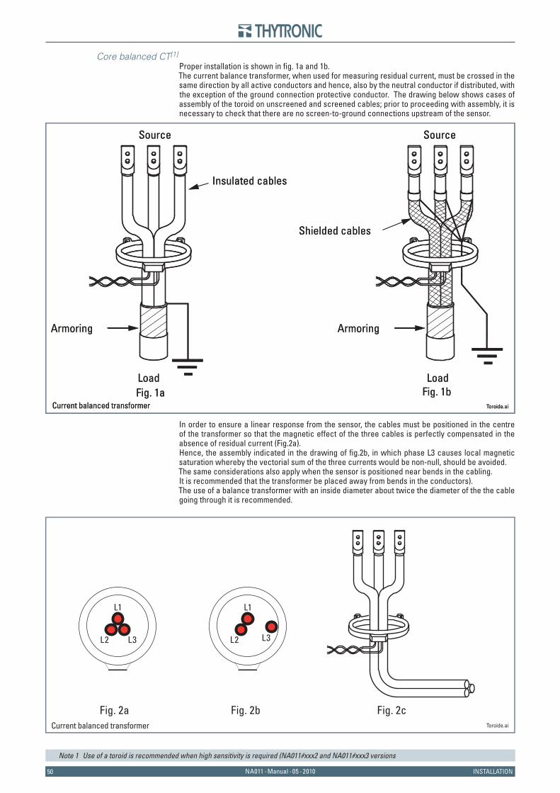
5050 NA011 - Manual - 05 - 2010 INSTALLATION
Core balanced CT[1]
Proper installation is shown in fi g. 1a and 1b.The current balance transformer, when used for measuring residual current, must be crossed in the same direction by all active conductors and hence, also by the neutral conductor if distributed, with the exception of the ground connection protective conductor. The drawing below shows cases of assembly of the toroid on unscreened and screened cables; prior to proceeding with assembly, it is necessary to check that there are no screen-to-ground connections upstream of the sensor.
In order to ensure a linear response from the sensor, the cables must be positioned in the centre of the transformer so that the magnetic effect of the three cables is perfectly compensated in the absence of residual current (Fig.2a). Hence, the assembly indicated in the drawing of fi g.2b, in which phase L3 causes local magnetic saturation whereby the vectorial sum of the three currents would be non-null, should be avoided. The same considerations also apply when the sensor is positioned near bends in the cabling. It is recommended that the transformer be placed away from bends in the conductors).The use of a balance transformer with an inside diameter about twice the diameter of the the cable going through it is recommended.
Note 1 Use of a toroid is recommended when high sensitivity is required (NA011#xxx2 and NA011#xxx3 versions
Fig. 1a Fig. 1b
Armoring
Load Load
Source Source
Insulated cables
Shielded cables
Armoring
Toroide.ai Current balanced transformerFig. 1a Fig. 1b
Armoring
Load Load
Source Source
Insulated cables
Shielded cables
Armoring
Toroide.ai Current balanced transformer
Fig. 2a Fig. 2b Fig. 2c
L1
L3L2
L1
L3L2
Toroide.ai Current balanced transformer
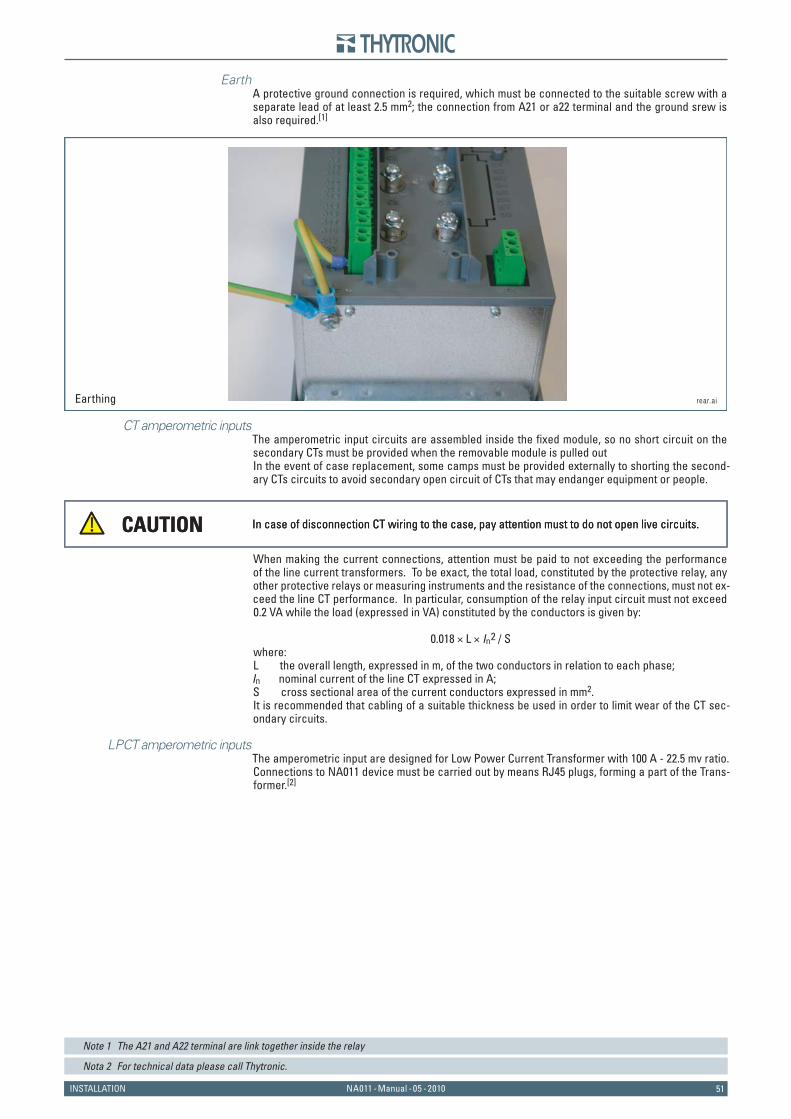
51NA011 - Manual - 05 - 2010INSTALLATION
EarthA protective ground connection is required, which must be connected to the suitable screw with a separate lead of at least 2.5 mm2; the connection from A21 or a22 terminal and the ground srew is also required.[1]
CT amperometric inputsThe amperometric input circuits are assembled inside the fi xed module, so no short circuit on the secondary CTs must be provided when the removable module is pulled outIn the event of case replacement, some camps must be provided externally to shorting the second-ary CTs circuits to avoid secondary open circuit of CTs that may endanger equipment or people.
When making the current connections, attention must be paid to not exceeding the performance of the line current transformers. To be exact, the total load, constituted by the protective relay, any other protective relays or measuring instruments and the resistance of the connections, must not ex-ceed the line CT performance. In particular, consumption of the relay input circuit must not exceed 0.2 VA while the load (expressed in VA) constituted by the conductors is given by:
0.018 × L × In2 / Swhere: L the overall length, expressed in m, of the two conductors in relation to each phase; In nominal current of the line CT expressed in A;S cross sectional area of the current conductors expressed in mm2.It is recommended that cabling of a suitable thickness be used in order to limit wear of the CT sec-ondary circuits.
LPCT amperometric inputsThe amperometric input are designed for Low Power Current Transformer with 100 A - 22.5 mv ratio. Connections to NA011 device must be carried out by means RJ45 plugs, forming a part of the Trans-former.[2]
Note 1 The A21 and A22 terminal are link together inside the relay
Nota 2 For technical data please call Thytronic.
In case of disconnection CT wiring to the case, pay attention must to do not open live circuits.CAUTION In case of disconnection CT wiring to the case, pay attention must to do not open live circuits.CAUTION
rear.aiEarthing
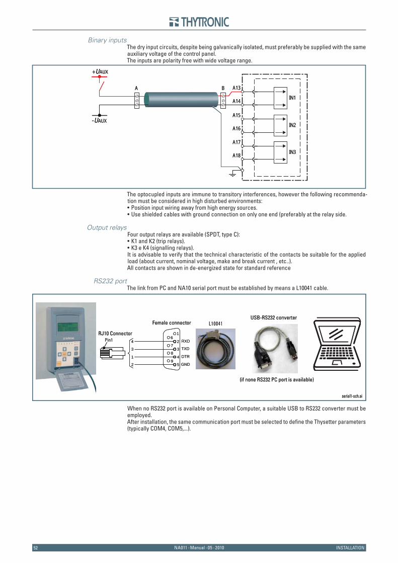
5252 NA011 - Manual - 05 - 2010 INSTALLATION
Binary inputsThe dry input circuits, despite being galvanically isolated, must preferably be supplied with the same auxiliary voltage of the control panel.The inputs are polarity free with wide voltage range.
The optocupled inputs are immune to transitory interferences, however the following recommenda-tion must be considered in high disturbed environments:
Position input wiring away from high energy sources.Use shielded cables with ground connection on only one end (preferably at the relay side.
Output relaysFour output relays are available (SPDT, type C):
K1 and K2 (trip relays).K3 e K4 (signalling relays).
It is advisable to verify that the technical characteristic of the contacts be suitable for the applied load (about current, nominal voltage, make and break current , etc..).All contacts are shown in de-energized state for standard reference
RS232 portThe link from PC and NA10 serial port must be established by means a L10041 cable.
When no RS232 port is available on Personal Computer, a suitable USB to RS232 converter must be employed.After installation, the same communication port must be selected to defi ne the Thysetter parameters (typically COM4, COM5,...).
••
••
+UAUX
-UAUX
A13
A14 IN1
A B
A15
A16 IN2
A17
A18 IN3
+UAUX
-UAUX
A13
A14 IN1
A B
A15
A16 IN2
A17
A18 IN3
serial1-sch.ai
L10041Female connector USB-RS232 converter
(if none RS232 PC port is available)
TXD
RXD
DTR
GND
4
3
1
2
1
2
3
4
6
7
8
95
RJ10 Connector Pin1
serial1-sch.ai
L10041Female connector USB-RS232 converter
(if none RS232 PC port is available)
TXD
RXD
DTR
GND
4
3
1
2
1
2
3
4
6
7
8
95
RJ10 Connector Pin1
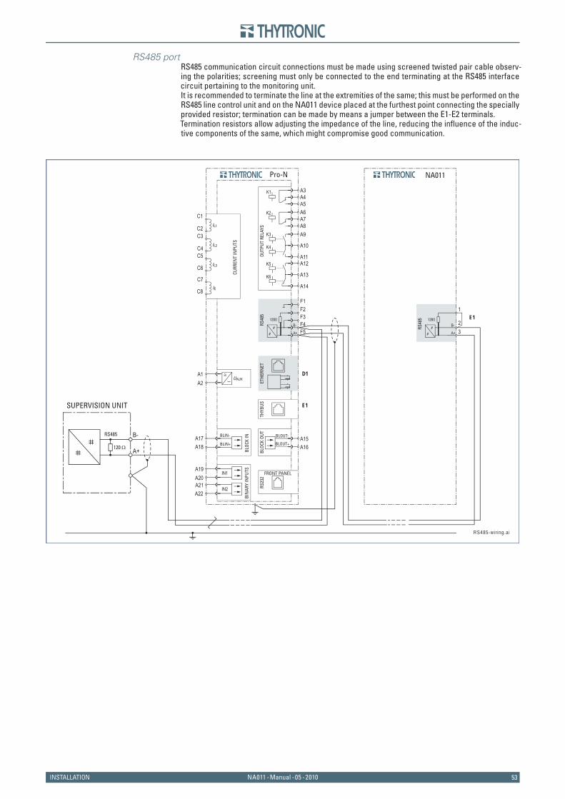
53NA011 - Manual - 05 - 2010INSTALLATION
RS485 portRS485 communication circuit connections must be made using screened twisted pair cable observ-ing the polarities; screening must only be connected to the end terminating at the RS485 interface circuit pertaining to the monitoring unit. It is recommended to terminate the line at the extremities of the same; this must be performed on the RS485 line control unit and on the NA011 device placed at the furthest point connecting the specially provided resistor; termination can be made by means a jumper between the E1-E2 terminals.Termination resistors allow adjusting the impedance of the line, reducing the infl uence of the induc-tive components of the same, which might compromise good communication.
RS485
120 Ω
SUPERVISION UNIT
OUTP
UT R
ELAY
S
UAUXA1 ≅
A2
A9
A10
A11A12
A13
A14
E1
E1
THYB
US
D1
ETHE
RNET
A3A4A5A6A7A8
K2
K3
K4
K5
K6
K1
RS48
5
F1F2F3F4F5A+
A+
B-
B-
BLOC
K OU
T
BLOC
K IN A15BLOUT-
BLOUT+ A16
BIN
ARY
INPU
TSA19
A18A17
IN1
IN2
A20A21A22
C1IL1
IL2
IL3
IE
CURR
ENT
INPU
TSC2C3
C4C5
C6
C7
C8
Pro-N
RS23
2
FRONT PANEL
RS485-wir ing.ai
NA011
RS48
5
1
23A+
B-
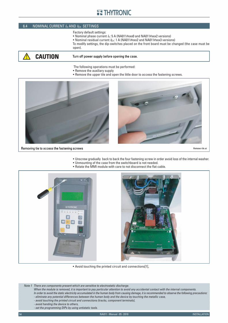
5454 NA011 - Manual - 05 - 2010 INSTALLATION
6.4 NOMINAL CURRENT In AND IEn SETTINGS
Factory default settings: Nominal phase current In: 5 A (NA011#xxx0 and NA011#xxx2 versions)Nominal residual current IEn: 1 A (NA011#xxx2 and NA011#xxx3 versions)
To modify settings, the dip-switches placed on the front board must be changed (the case must be open).
The following operations must be performed:Remove the auxiliary supplyRemove the upper tile and open the little door to access the fastening screws.
Unscrew gradually back to back the four fastening screw in order avoid loss of the internal washer.Unmounting of the case from the switchboard is not needed.Rotate the MMI module with care to not disconnect the fl at cable.
Avoid touching the printed circuit and connections[1],
Note 1 There are components present which are sensitive to electrostatic discharge. When the module is removed, it is important to pay particular attention to avoid any accidental contact with the internal components. In order to avoid the static electricity accumulated in the human body from causing damage, it is recommended to observe the following precautions: - eliminate any potential differences between the human body and the device by touching the metallic case, - avoid touching the printed circuit and connections (tracks, component terminals), - avoid handing the device to others, - set the programming DIPs by using antistatic tools.
••
••
•••
•
Turn off power supply before opening the case.CAUTION Turn off power supply before opening the case.CAUTION
Remove-t i le.aiRemoving tie to access the fastening screws Remove-t i le.aiRemoving tie to access the fastening screws
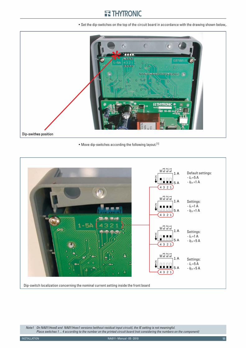
55NA011 - Manual - 05 - 2010INSTALLATION
Set the dip-switches on the top of the circuit board in accordance with the drawing shown below,.
Move dip-switches according the following layout.[1]
Note1 On NA011#xxx0 and NA011#xxx1 versions (without residual input circuit), the IE setting is not meaningful. Place switches 1 ... 4 according to the number on the printed circuit board (not considering the numbers on the component)
•
•
Dip-swithes positionDip-swithes position
Dip-switch localization concerning the nominal current setting inside the front board
Default settings:- In =5 A- IEn =1 A
Settings:- In =5 A- IEn =5 A
Settings:- In =1 A- IEn =1 A
Settings:- In =1 A- IEn =5 A
1 A
5 A
ON
IL1
IL3
IL2
IE
1 A
5 A
ON
IL1
IL3
IL2
IE
1 A
5 A
ON
IL1
IL3
IL2
IE
1 A
5 A
ON
IL1
IL3
IL2
IE
1234
1234
1234
1234
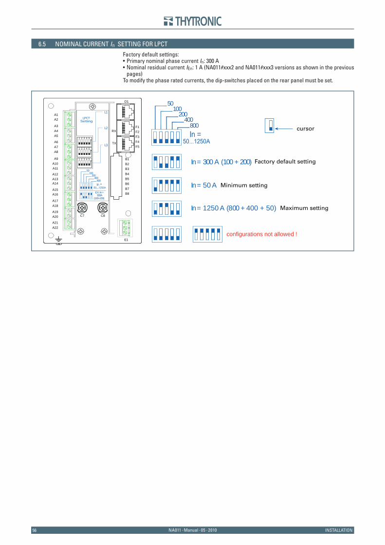
5656 NA011 - Manual - 05 - 2010 INSTALLATION
6.5 NOMINAL CURRENT In SETTING FOR LPCT
Factory default settings: Primary nominal phase current In: 300 ANominal residual current IEn: 1 A (NA011#xxx2 and NA011#xxx3 versions as shown in the previous pages)
To modify the phase rated currents, the dip-switches placed on the rear panel must be set.
••
C7 C8
F1
D1
RX
TX
F2F3F4F5
A1A2
A3A4A5
A6A7A8
A9A10A11
A12A13A14
A15A16
A17A18
A19A20
A21A22
B1B2B3B4B5B6B7B8
E1
31
2
LPCTSetting
(100+200)300A
EX. In=
50
200400
100
800
50
200400
100
800
L3
L2
L1
1 2 3 4 5
1 2 3 4 5
1 2 3 4 5 In= 300 A (100 + 200) Factory default setting
In= 50 A Minimum setting
In= 1250 A (800 + 400 + 50) Maximum setting
configurations not allowed !
cursor
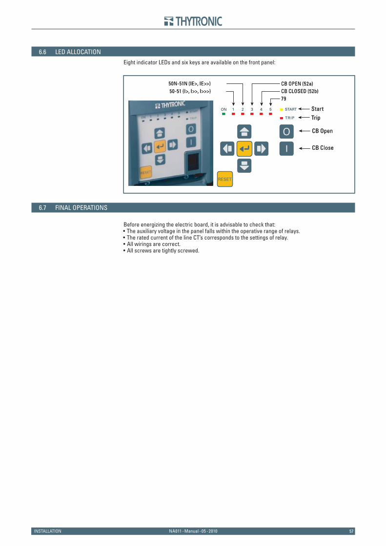
57NA011 - Manual - 05 - 2010INSTALLATION
6.6 LED ALLOCATION
Eight indicator LEDs and six keys are available on the front panel:
6.7 FINAL OPERATIONS
Before energizing the electric board, it is advisable to check that:The auxiliary voltage in the panel falls within the operative range of relays.The rated current of the line CT’s corresponds to the settings of relay.All wirings are correct.All screws are tightly screwed.
••••
Start
79CB CLOSED (52b)CB OPEN (52a)
50-51 (I>, I>>, I>>>)50N-51N (IE>, IE>>)
Trip
CB Open
CB Close
Start
79CB CLOSED (52b)CB OPEN (52a)
50-51 (I>, I>>, I>>>)50N-51N (IE>, IE>>)
Trip
CB Open
CB Close
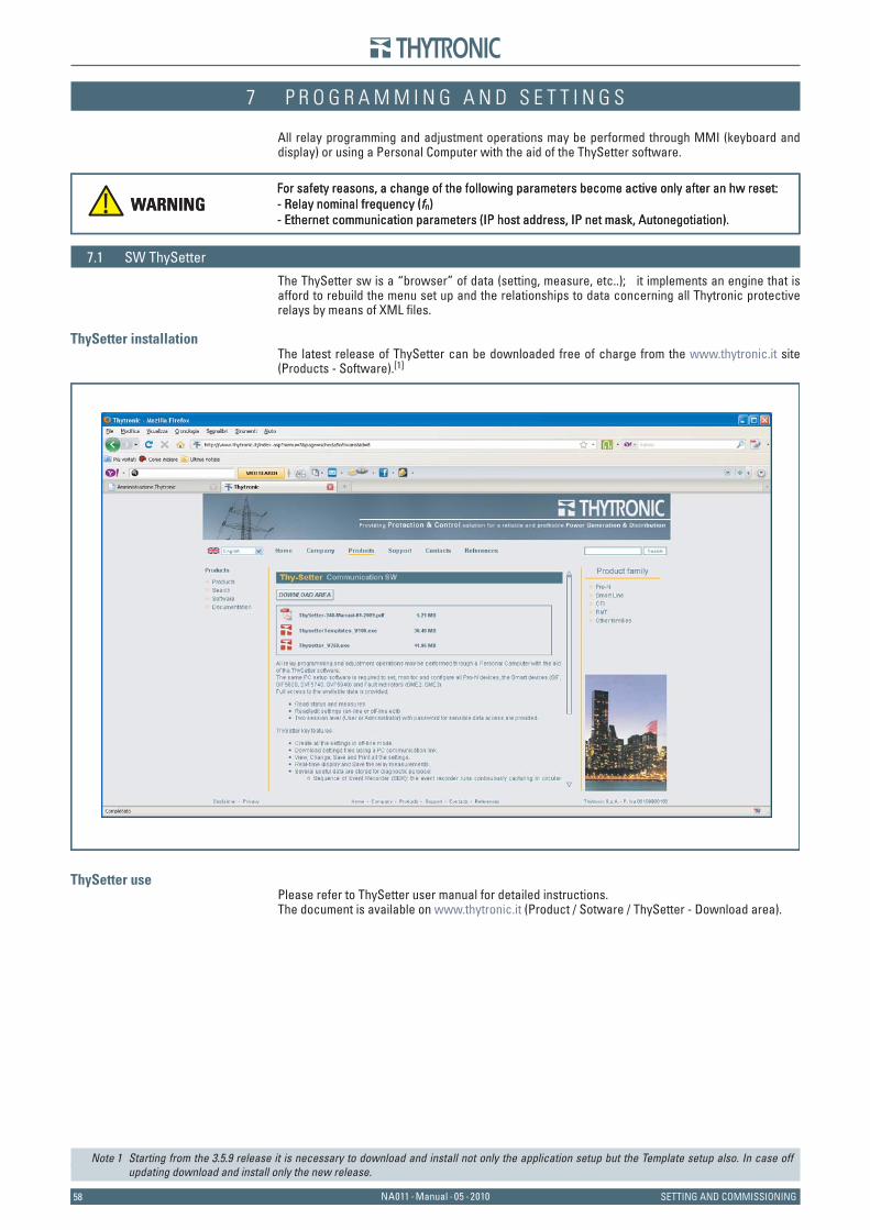
5858 NA011 - Manual - 05 - 2010 SETTING AND COMMISSIONING
7 P R O G R A M M I N G A N D S E T T I N G S7 P R O G R A M M I N G A N D S E T T I N G S
All relay programming and adjustment operations may be performed through MMI (keyboard and display) or using a Personal Computer with the aid of the ThySetter software.
7.1 SW ThySetter
The ThySetter sw is a “browser” of data (setting, measure, etc..); it implements an engine that is afford to rebuild the menu set up and the relationships to data concerning all Thytronic protective relays by means of XML fi les.
ThySetter installationThe latest release of ThySetter can be downloaded free of charge from the www.thytronic.it site (Products - Software).[1]
ThySetter usePlease refer to ThySetter user manual for detailed instructions.The document is available on www.thytronic.it (Product / Sotware / ThySetter - Download area).
Note 1 Starting from the 3.5.9 release it is necessary to download and install not only the application setup but the Template setup also. In case off updating download and install only the new release.
WARNINGFor safety reasons, a change of the following parameters become active only after an hw reset:- Relay nominal frequency (fn)- Ethernet communication parameters (IP host address, IP net mask, Autonegotiation).
WARNINGFor safety reasons, a change of the following parameters become active only after an hw reset:- Relay nominal frequency (fn)- Ethernet communication parameters (IP host address, IP net mask, Autonegotiation).
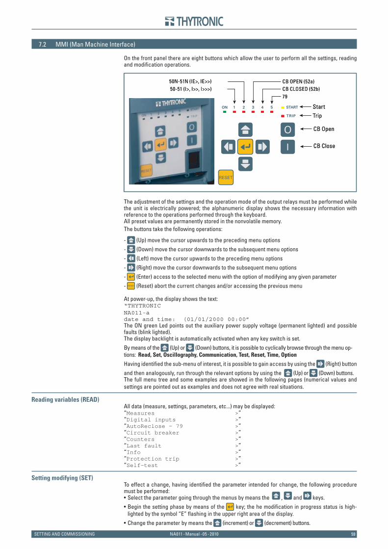
59NA011 - Manual - 05 - 2010SETTING AND COMMISSIONING
7.2 MMI (Man Machine Interface)
On the front panel there are eight buttons which allow the user to perform all the settings, reading and modifi cation operations.
The adjustment of the settings and the operation mode of the output relays must be performed while the unit is electrically powered; the alphanumeric display shows the necessary information with reference to the operations performed through the keyboard. All preset values are permanently stored in the nonvolatile memory.The buttons take the following operations:
- (Up) move the cursor upwards to the preceding menu options
- (Down) move the cursor downwards to the subsequent menu options
- (Left) move the cursor upwards to the preceding menu options
- (Right) move the cursor downwards to the subsequent menu options
- (Enter) access to the selected menu with the option of modifying any given parameter
- (Reset) abort the current changes and/or accessing the previous menu
At power-up, the display shows the text:“THYTRONICNA011-adate and time: (01/01/2000 00:00”The ON green Led points out the auxiliary power supply voltage (permanent lighted) and possible faults (blink lighted).The display backlight is automatically activated when any key switch is set.
By means of the (Up) or (Down) buttons, it is possible to cyclically browse through the menu op-tions: Read, Set, Oscillography, Communication, Test, Reset, Time, Option
Having identifi ed the sub-menu of interest, it is possible to gain access by using the (Right) button
and then analogously, run through the relevant options by using the (Up) or (Down) buttons. The full menu tree and some examples are showed in the following pages (numerical values and settings are pointed out as examples and does not agree with real situations.
Reading variables (READ)All data (measure, settings, parameters, etc...) may be displayed:“Measures >”“Digital inputs >”“AutoReclose - 79 >”“Circuit breaker >”“Counters >”“Last fault >”“Info >”“Protection trip >”“Self-test >”
Setting modifying (SET)To effect a change, having identifi ed the parameter intended for change, the following procedure must be performed:
Select the parameter going through the menus by means the , and keys.
Begin the setting phase by means of the key; the he modifi cation in progress status is high-lighted by the symbol “E” fl ashing in the upper right area of the display.
Change the parameter by means the (increment) or (decrement) buttons.
•
•
•
Start
79CB CLOSED (52b)CB OPEN (52a)
50-51 (I>, I>>, I>>>)50N-51N (IE>, IE>>)
Trip
CB Open
CB Close
Start
79CB CLOSED (52b)CB OPEN (52a)
50-51 (I>, I>>, I>>>)50N-51N (IE>, IE>>)
Trip
CB Open
CB Close
6060 NA011 - Manual - 05 - 2010 SETTING AND COMMISSIONING
Press the (Enter) button; acceptance of the change is indicated by the disappearance of the fl ashing “E” to be replaced by the symbol “!”. On must be remember that changes are NOT ac-tive until the Store command, located in the “Set” menu has been used; in this regard, once the
“Store” message is displayed, it is necessary to use the (Enter) button; this results in the
“execute” message with the symbol “C” fl ashing.
Browse the menu by means of the and or keys to go in the Store menu.
Press the (Enter) button; once more concludes the save procedure with the temporary appear-
ance of the message “ok!”. After one or more modifi cations, the status of having data that has still not been permanently saved is indicated by the “!” symbol in the top right and the display message “WARNING set Clear..
Store” which appears while browsing through the main menu with the use of the or keys. The Clear command may be used to abandon unsaved changes (prior to use of the Store com-mand); the same effect is achieved by switching the key to the OFF position or removing the auxil-iary power supply to the relay.
ExampleTo set the K1 relay with Energized mode and latched mode (Energized, Latched) the following sequence must be operated:
Select the Set menu “Set >”by means of the key.
Press the key; the message “Base >” is displayed.
Browse the menus with “Relays >”“50/51 >”“50N/51N >”“AutoReclose - 79 >”“Circuit breaker >”“Clear >”“Store >”
Select the “Relays >”, menu; the message “K1 None >” is displayed.
Press the key; the message “K1 Logic De-energized” is displayed.
Press the key; the he modifi cation in progress status is highlighted by the symbol “E” fl ashing in the upper right area of the display.
Change the parameter by means the or keys; the message “K1 Logic Energized” is displayed.
Press the key; acceptance of the change is indicated by the disappearance of the fl ashing “E” to be replaced by the symbol “!”.
Press the key; the message “K1 mode No-latched” is displayed.
Press the key; acceptance of the change is indicated by the disappearance of the fl ashing “E” to be replaced by the symbol “!”.
Change the parameter by means the (increment) or (decrement) buttons; the message “K1 mode Latched” is displayed.
Press the (Enter) button; acceptance of the change is indicated by the disappearance of the fl ashing “E” to be replaced by the symbol “!”
Press the key and or to go inside the Store menu.
Press the key; this results in the “execute ?” message with the symbol “C” fl ashing.
Answer with key to confi rm setting.The end of the setting sequence is signalled by the “ok!” message.
The Reset key may be used to abort unsaved changes (prior to use of the Store command); the same effect is achieved by switching the key to the OFF position or removing the auxiliary power supply to the NA011 relay.
TestThe operational tests with or without command of the associated output relays may be performed.
Browse the main menu by means the or keys until the “Test” message is displayed; press
the key to enter and subsequently select the test by means of the or keys.
Test I> ledTest I>> ledTest I>>> ledTest IE> ledTest IE>> ledTest I> fullTest I>> fullTest I>>> full
•
•
•
•
•
•
•
•
•
•
•
•
•
•
•
•
•
•
•
••••••••
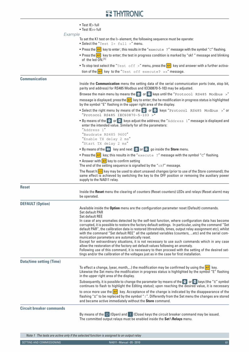
61NA011 - Manual - 05 - 2010SETTING AND COMMISSIONING
Test IE> fullTest IE>> full
ExampleTo set the K1 test on the I> element, the following sequence must be operate:
Select the “Test I> full >” menu.
Press the key to enter ; this results in the “execute ?” message with the symbol “C” fl ashing.
Press the key to enter; the test in progress condition is marked by “ok! “ message and blinking of the led ON.[1]
To stop test select the “Test off >” menu, press the key and answer with a further activa-
tion of the key to the “Test off execute? >>” message.
CommunicationInside the Communication menu the setting data of the serial communication ports (rate, stop bit, parity and address) for RS485 Modbus and IEC60870-5-103 may be adjusted.
Browse the main menu by means the or keys until the “Protocol RS485 Modbus >”
message is displayed; press the key to enter; the he modifi cation in progress status is highlighted by the symbol “E” fl ashing in the upper right area of the display.
Select the right menu by means of the or keys “Protocol RS485 Modbus >” or “Protocol RS485 IEC60870-5-103 >”
By means of the or keys adjust the address; the “Address 1” message is displayed and enter the intended value. Similarly for all the parameters:
“Address 1” “Baudrate RS485 9600” “Enable TX delay 2 ms” “Start TX delay 2 ms”
By means of the key and next or go inside the Store menu.
Press the key; this results in the “execute ?” message with the symbol “C” fl ashing.
Answer with key to confi rm settingThe end of the setting sequence is signalled by the “ok!” message.
The Reset h key may be used to abort unsaved changes (prior to use of the Store command); the same effect is achieved by switching the key to the OFF position or removing the auxiliary power supply to the NA011 relay.
ResetInside the Reset menu the clearing of counters (Reset counters) LEDs and relays (Reset alarm) may be operated.
DEFAULT (Option)Available inside the Option menu are the confi guration parameter reset (Default) commands.Set default PARSet default REEIn case of any anomalies detected by the self-test function, where confi guration data has become corrupted, it is possible to restore the factory default settings. In particular, using the command “Set default PAR”, the calibration data is restored (thresholds, times, output relay assignment etc), whilst with the command “Set default REE” all the updated variables (counters, ...etc) and the serial com-munication parameters are automatically reset. Except for extraordinary situations, it is not necessary to use such commands which in any case allow the restoration of the factory set default values following an anomaly. Following use of this command, it is necessary to then proceed with the setting of the desired set-tings and/or the calibration of the voltages just as in the case for first installation.
Data/time setting (Time)To effect a change, (year, month,...) the modifi cation may be confi rmed by using the key. Likewise the Set menu the modifi cation in progress status is highlighted by the symbol “E” fl ashing in the upper right area of the display.
Subsequently, it is possible to change the parameter by means of the or keys (the “E” symbol continues to flash to highlight the Editing status); upon reaching the desired value, it is necessary
to once more use the key. Acceptance of the change is indicated by the disappearance of the flashing “E” to be replaced by the symbol “!”. Differently from the Set menu the changes are stored and became active immediately without the Store command.
Circuit breaker commandsBy means of the (Open) and (Close) keys the circuit breaker command may be issued.The committed output relays must be enabled inside the Set \ Relays menu.
Note 1 The tests are active only if the selected function is assigned to an output relay
••
•
•
•
•
•
•
•
•
•
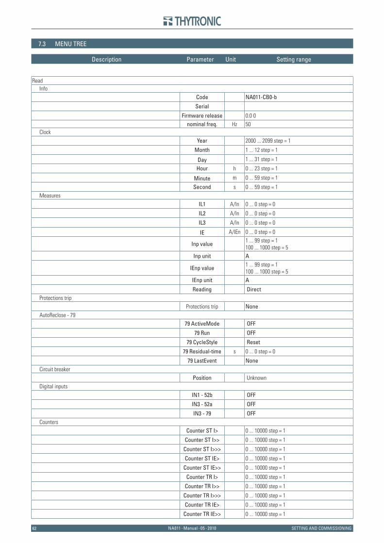
6262 NA011 - Manual - 05 - 2010 SETTING AND COMMISSIONING
7.3 MENU TREE
Read Info
Code NA011-CB0-b
Serial Firmware release 0.0 0 nominal freq. Hz 50
Clock
Year 2000 ... 2099 step = 1
Month 1 ... 12 step = 1
Day 1 ... 31 step = 1
Hour h 0 ... 23 step = 1
Minute m 0 ... 59 step = 1
Second s 0 ... 59 step = 1 Measures
IL1 A/In 0 ... 0 step = 0
IL2 A/In 0 ... 0 step = 0
IL3 A/In 0 ... 0 step = 0
IE A/IEn 0 ... 0 step = 0
Inp value 1 ... 99 step = 1100 ... 1000 step = 5
Inp unit A
IEnp value 1 ... 99 step = 1100 ... 1000 step = 5
IEnp unit A Reading Direct
Protections trip
Protections trip None AutoReclose - 79
79 ActiveMode OFF
79 Run OFF
79 CycleStyle Reset
79 Residual-time s 0 ... 0 step = 0
79 LastEvent None Circuit breaker
Position Unknown Digital inputs
IN1 - 52b OFF
IN3 - 52a OFF
IN3 - 79 OFF Counters
Counter ST I> 0 ... 10000 step = 1
Counter ST I>> 0 ... 10000 step = 1
Counter ST I>>> 0 ... 10000 step = 1
Counter ST IE> 0 ... 10000 step = 1
Counter ST IE>> 0 ... 10000 step = 1
Counter TR I> 0 ... 10000 step = 1
Counter TR I>> 0 ... 10000 step = 1
Counter TR I>>> 0 ... 10000 step = 1
Counter TR IE> 0 ... 10000 step = 1
Counter TR IE>> 0 ... 10000 step = 1
Description Parameter Unit Setting range
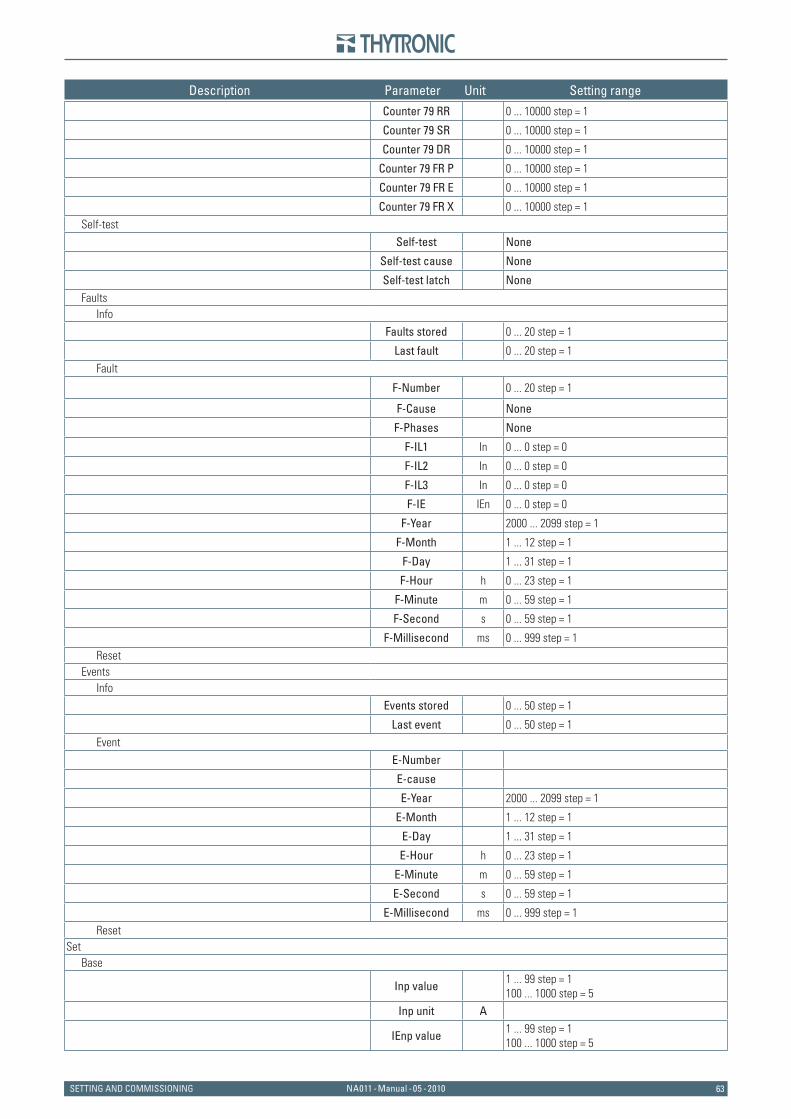
63NA011 - Manual - 05 - 2010SETTING AND COMMISSIONING
Description Parameter Unit Setting range
Counter 79 RR 0 ... 10000 step = 1
Counter 79 SR 0 ... 10000 step = 1
Counter 79 DR 0 ... 10000 step = 1
Counter 79 FR P 0 ... 10000 step = 1
Counter 79 FR E 0 ... 10000 step = 1
Counter 79 FR X 0 ... 10000 step = 1 Self-test
Self-test None
Self-test cause None
Self-test latch None Faults
Info
Faults stored 0 ... 20 step = 1
Last fault 0 ... 20 step = 1 Fault
F-Number 0 ... 20 step = 1
F-Cause None
F-Phases None
F-IL1 In 0 ... 0 step = 0
F-IL2 In 0 ... 0 step = 0
F-IL3 In 0 ... 0 step = 0
F-IE IEn 0 ... 0 step = 0
F-Year 2000 ... 2099 step = 1
F-Month 1 ... 12 step = 1
F-Day 1 ... 31 step = 1
F-Hour h 0 ... 23 step = 1
F-Minute m 0 ... 59 step = 1
F-Second s 0 ... 59 step = 1
F-Millisecond ms 0 ... 999 step = 1 Reset
Events Info
Events stored 0 ... 50 step = 1
Last event 0 ... 50 step = 1 Event
E-Number E-cause E-Year 2000 ... 2099 step = 1
E-Month 1 ... 12 step = 1
E-Day 1 ... 31 step = 1
E-Hour h 0 ... 23 step = 1
E-Minute m 0 ... 59 step = 1
E-Second s 0 ... 59 step = 1
E-Millisecond ms 0 ... 999 step = 1 Reset
Set Base
Inp value 1 ... 99 step = 1100 ... 1000 step = 5
Inp unit A
IEnp value 1 ... 99 step = 1100 ... 1000 step = 5
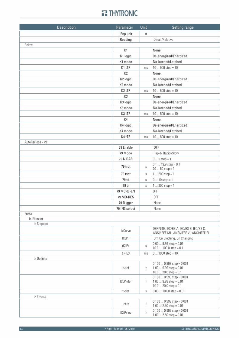
6464 NA011 - Manual - 05 - 2010 SETTING AND COMMISSIONING
Description Parameter Unit Setting range
IEnp unit A Reading Direct/Relative
Relays
K1 None
K1 logic De -energized/Energized
K1 mode No-latched/Latched
K1 tTR ms 10 ... 500 step = 10
K2 None
K2 logic De -energized/Energized
K2 mode No-latched/Latched
K2 tTR ms 10 ... 500 step = 10
K3 None
K3 logic De -energized/Energized
K3 mode No-latched/Latched
K3 tTR ms 10 ... 500 step = 10
K4 None
K4 logic De -energized/Energized
K4 mode No-latched/Latched
K4 tTR ms 10 ... 500 step = 10 AutoReclose - 79
79 Enable OFF
79 Mode Rapid / Rapid+Slow
79 N.DAR 0 ... 5 step = 1
79 trdt s 0.1 ... 19.9 step = 0.120 ... 60 step = 1
79 tsdt s 1 ... 200 step = 1
79 td s 0 ... 10 step = 1
79 tr s 1 ... 200 step = 1
79 MC-td-EN OFF
79 MO-RES OFF
79 Trigger None
79 IN3 select None 50/51
I> Element I> Setpoint
I>Curve DEFINITE, IEC/BS A, IEC/BS B, IEC/BS C,ANSI/IEEE MI , ANSI/IEEE VI , ANSI/IEEE EI
ICLP> Off, On Bloching, On Changing
tCLP> s 0.00 ... 9.99 step = 0.0110.0 ... 100.0 step = 0.1
t>RES ms 0 ... 1000 step = 10 I> Defi nite
I>def In 0.100 ... 0.999 step = 0.0011.00 ... 9.99 step = 0.0110.0 ... 20.0 step = 0.1
ICLP>def In 0.100 ... 0.999 step = 0.0011.00 ... 9.99 step = 0.0110.0 ... 20.0 step = 0.1
t>def s 0.03 ... 10.00 step = 0.01 I> Inverse
I>inv In 0.100 ... 0.999 step = 0.0011.00 ... 2.50 step = 0.01
ICLP>inv In 0.100 ... 0.999 step = 0.0011.00 ... 2.50 step = 0.01
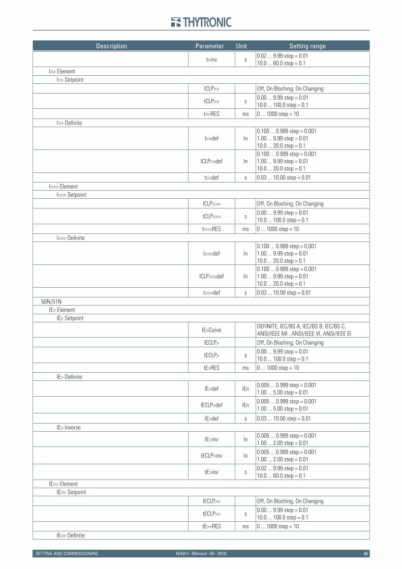
65NA011 - Manual - 05 - 2010SETTING AND COMMISSIONING
Description Parameter Unit Setting range
t>inv s 0.02 ... 9.99 step = 0.0110.0 ... 60.0 step = 0.1
I>> Element I>> Setpoint
ICLP>> Off, On Bloching, On Changing
tCLP>> s 0.00 ... 9.99 step = 0.0110.0 ... 100.0 step = 0.1
t>>RES ms 0 ... 1000 step = 10 I>> Defi nite
I>>def In 0.100 ... 0.999 step = 0.0011.00 ... 9.99 step = 0.0110.0 ... 20.0 step = 0.1
ICLP>>def In 0.100 ... 0.999 step = 0.0011.00 ... 9.99 step = 0.0110.0 ... 20.0 step = 0.1
t>>def s 0.03 ... 10.00 step = 0.01 I>>> Element
I>>> Setpoint
ICLP>>> Off, On Bloching, On Changing
tCLP>>> s 0.00 ... 9.99 step = 0.0110.0 ... 100.0 step = 0.1
t>>>RES ms 0 ... 1000 step = 10 I>>> Defi nite
I>>>def In 0.100 ... 0.999 step = 0.0011.00 ... 9.99 step = 0.0110.0 ... 20.0 step = 0.1
ICLP>>>def In 0.100 ... 0.999 step = 0.0011.00 ... 9.99 step = 0.0110.0 ... 20.0 step = 0.1
t>>>def s 0.03 ... 10.00 step = 0.01 50N/51N
IE> Element IE> Setpoint
IE>Curve DEFINITE, IEC/BS A, IEC/BS B, IEC/BS C,ANSI/IEEE MI , ANSI/IEEE VI , ANSI/IEEE EI
IECLP> Off, On Bloching, On Changing
tECLP> s 0.00 ... 9.99 step = 0.0110.0 ... 100.0 step = 0.1
tE>RES ms 0 ... 1000 step = 10 IE> Defi nite
IE>def IEn 0.005 ... 0.999 step = 0.0011.00 ... 5.00 step = 0.01
IECLP>def IEn 0.005 ... 0.999 step = 0.0011.00 ... 5.00 step = 0.01
tE>def s 0.03 ... 10.00 step = 0.01 IE> Inverse
IE>inv In 0.005 ... 0.999 step = 0.0011.00 ... 2.00 step = 0.01
IECLP>inv In 0.005 ... 0.999 step = 0.0011.00 ... 2.00 step = 0.01
tE>inv s 0.02 ... 9.99 step = 0.0110.0 ... 60.0 step = 0.1
IE>> Element IE>> Setpoint
IECLP>> Off, On Bloching, On Changing
tECLP>> s 0.00 ... 9.99 step = 0.0110.0 ... 100.0 step = 0.1
tE>>RES ms 0 ... 1000 step = 10 IE>> Defi nite
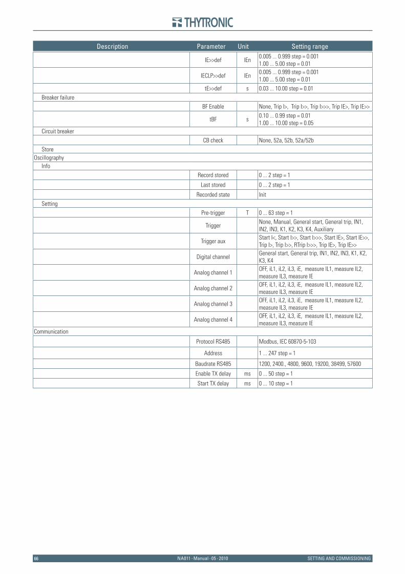
6666 NA011 - Manual - 05 - 2010 SETTING AND COMMISSIONING
Description Parameter Unit Setting range
IE>>def IEn 0.005 ... 0.999 step = 0.0011.00 ... 5.00 step = 0.01
IECLP>>def IEn 0.005 ... 0.999 step = 0.0011.00 ... 5.00 step = 0.01
tE>>def s 0.03 ... 10.00 step = 0.01 Breaker failure
BF Enable None , Trip I>, Trip I>>, Trip I>>>, Trip IE>, Trip IE>>
tBF s 0.10 ... 0.99 step = 0.011.00 ... 10.00 step = 0.05
Circuit breaker
CB check None, 52a, 52b, 52a/52b Store
Oscillography Info
Record stored 0 ... 2 step = 1
Last stored 0 ... 2 step = 1
Recorded state Init Setting
Pre-trigger T 0 ... 63 step = 1
Trigger None, Manual, General start, General trip, IN1, IN2, IN3, K1, K2, K3, K4, Auxiliary
Trigger aux Start I<, Start I>>, Start I>>>, Start IE>, Start IE>>, Trip I>, Trip I>>, RTrip I>>>, Trip IE>, Trip IE>>
Digital channel General start, General trip, IN1, IN2, IN3, K1, K2, K3, K4
Analog channel 1 OFF, iL1, iL2, iL3, iE, measure IL1, measure IL2, measure IL3, measure IE
Analog channel 2 OFF, iL1, iL2, iL3, iE, measure IL1, measure IL2, measure IL3, measure IE
Analog channel 3 OFF, iL1, iL2, iL3, iE, measure IL1, measure IL2, measure IL3, measure IE
Analog channel 4 OFF, iL1, iL2, iL3, iE, measure IL1, measure IL2, measure IL3, measure IE
Communication
Protocol RS485 Modbus, IEC 60870-5-103
Address 1 ... 247 step = 1
Baudrate RS485 1200, 2400., 4800, 9600, 19200 , 38499, 57600
Enable TX delay ms 0 ... 50 step = 1
Start TX delay ms 0 ... 10 step = 1

67NA011 - Manual - 05 - 2010SETTING AND COMMISSIONING
7.4 MAINTENANCE
The devices do not require any particular maintenance; all circuits use high quality static com-ponents, the subassembly products undergo dynamic checks on their functioning before the fi nal assembling of the complete equipment. The dedicated circuits and the fi rmware for the self-test function continuously check the relay operation; the continuously operating auto-zeroing function dynamically corrects the measuring errors due to offset, heat dependent drifts, aging of components, etc.The microprocessor is equipped with a watch-dog circuit which restores the correct operation of the fi rmware in case of fault.The possibility of reading the value of the signals measured on the display (the relay used as an am-meter) allows one to check both the system parameters and the operation of the protection relays at any time. The relay can be preset as well to show the current values referred to the nominal current of the current transformers, as directly in primary amperes (according to the preset value of CT’s nominal primary current); the same is done for the input voltages.If connected to the central control unit, all data available on the display can be checked and pro-cessed thus performing a continuous check and maintenance.
7.5 REPAIR
No repair of possible faults by the client is foreseen; if following to any irregularity of operation, the above tests confi rm the presence of a fault, it will be necessary to send the relay to the factory for the repair and the consequent settings and checks.
7.6 PACKAGING
The devices must be stored within the required temperature limits; the relative humidity should not cause condensation or formation of frost.It is recommended that the devices are stored in their packaging; in the case of long storage, espe-cially in extreme climatic conditions, it is recommended that the device is supplied with power for some hours before the commissioning, in order to bring the circuits to the rating conditions and to stabilize the operation of the components.
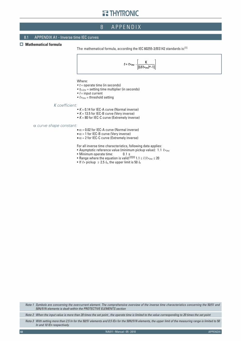
6868 NA011 - Manual - 05 - 2010 APPENDIX
8 A P P E N D I X8 A P P E N D I X
8.1 APPENDIX A1 - Inverse time IEC curves
Mathematical formulaThe mathematical formula, according the IEC 60255-3/BS142 standards is:[1]
Where:t = operate time (in seconds)tI>inv = setting time multiplier (in seconds)I = input currentI>inv = threshold setting
K coeffi cient:K = 0.14 for IEC-A curve (Normal inverse)K = 13.5 for IEC-B curve (Very inverse)K = 80 for IEC-C curve (Extremely inverse)
α curve shape constant:α = 0.02 for IEC-A curve (Normal inverse)α = 1 for IEC-B curve (Very inverse)α = 2 for IEC-C curve (Extremely inverse)
For all inverse time characteristics, following data applies:Asymptotic reference value (minimum pickup value): 1.1 I>invMinimum operate time: 0.1 sRange where the equation is valid:[2][3] 1.1 ≤ I /I>inv ≤ 20 If I> pickup ≥ 2.5 In, the upper limit is 50 In
Note 1 Symbols are concerning the overcurrent element. The comprehensive overview of the inverse time characteristics concerning the 50/51 and 50N/51N elements is dealt within the PROTECTIVE ELEMENTS section
Note 2 When the input value is more than 20 times the set point , the operate time is limited to the value corresponding to 20 times the set point
Nota 3 With setting more than 2.5 In for the 50/51 elements and 0.5 IEn for the 50N/51N elements, the upper limit of the measuring range is limited to 50 In and 10 IEn respectively.
••••
•••
•••
••••
t = t>inv · [(I/I>inv)α-1]
Kt = t>inv · [(I/I>inv)α-1]
K
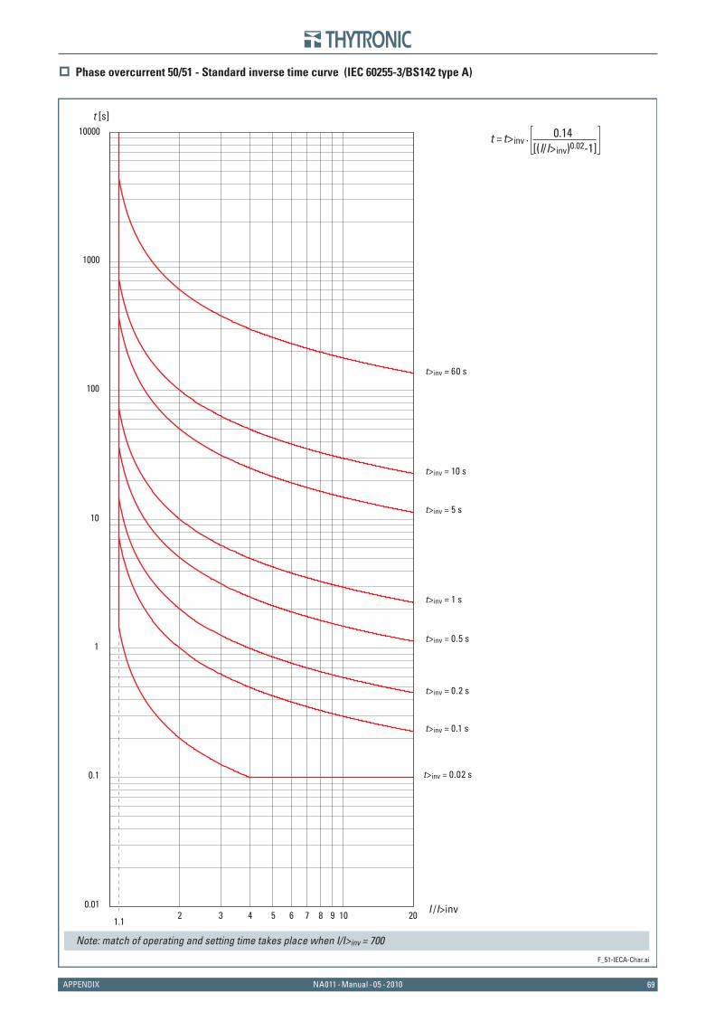
69NA011 - Manual - 05 - 2010APPENDIX
Phase overcurrent 50/51 - Standard inverse time curve (IEC 60255-3/BS142 type A)
F_51-IECA-Char.ai
1.12 3 4 5 6 7 8 9 10 20 I /I>inv0.01
0.1
1
10
100
1000
10000t [s]
t>inv = 10 s
t>inv = 60 s
t>inv = 5 s
t>inv = 1 s
t>inv = 0.5 s
t>inv = 0.2 s
t>inv = 0.1 s
t>inv = 0.02 s
t = t>inv · [(I/I>inv)0.02-1]
0.14
Note: match of operating and setting time takes place when I/I>inv = 700
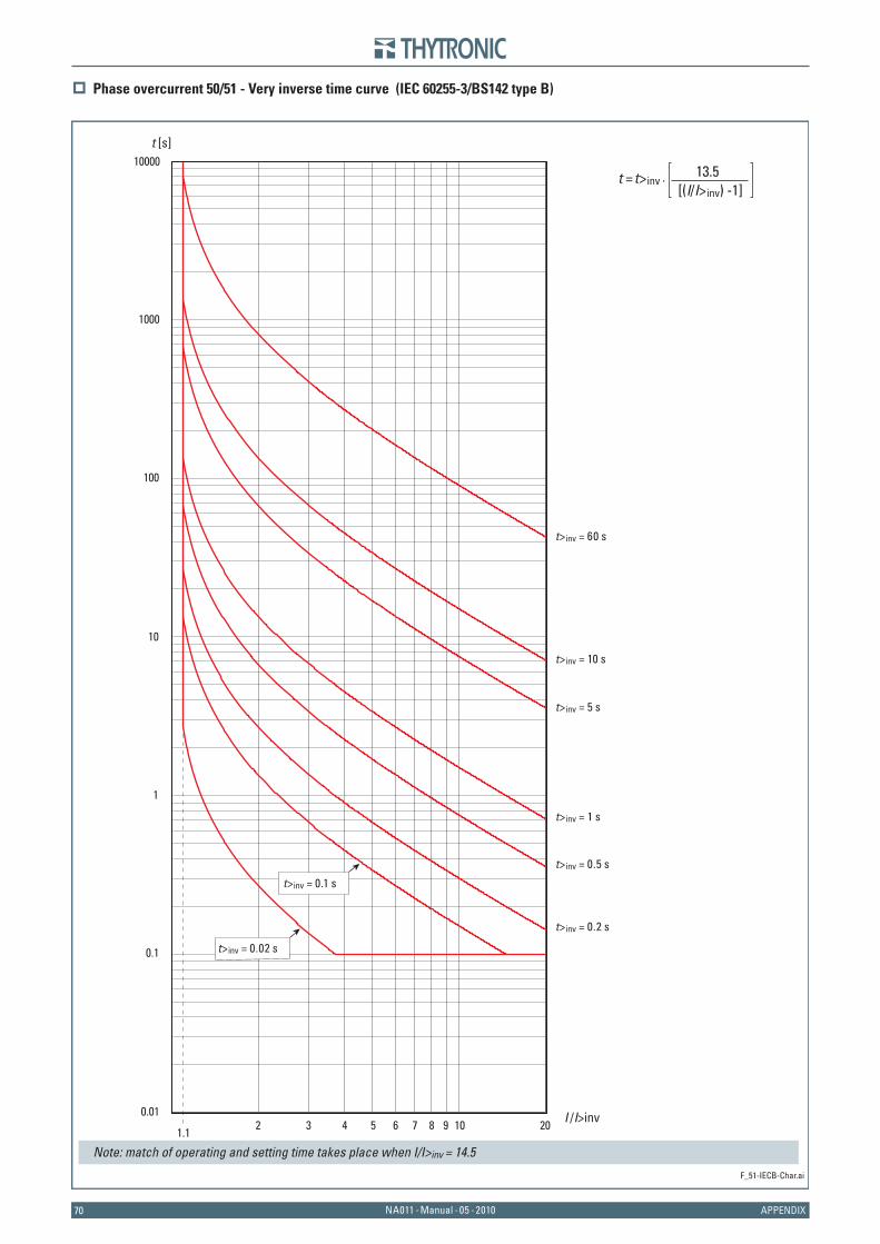
7070 NA011 - Manual - 05 - 2010 APPENDIX
Phase overcurrent 50/51 - Very inverse time curve (IEC 60255-3/BS142 type B)
F_51-IECB-Char.ai
1.12 3 4 5 6 7 8 9 10 20 I /I>inv0.01
0.1
1
10
100
1000
10000t [s]
t>inv = 10 s
t>inv = 60 s
t>inv = 5 s
t>inv = 1 s
t>inv = 0.5 s
t>inv = 0.2 s
t>inv = 0.02 s
t>inv = 0.1 s
t = t>inv · [(I/I>inv) -1]
13.5
Note: match of operating and setting time takes place when I/I>inv = 14.5
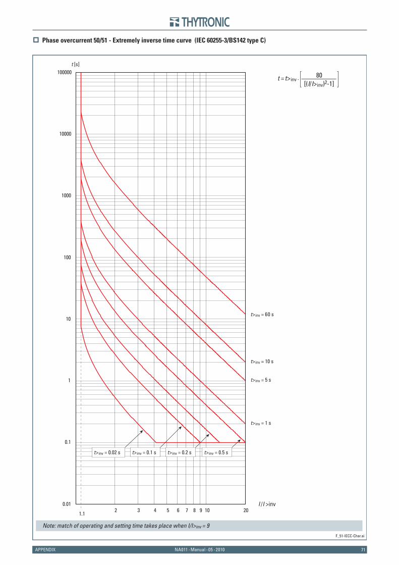
71NA011 - Manual - 05 - 2010APPENDIX
Phase overcurrent 50/51 - Extremely inverse time curve (IEC 60255-3/BS142 type C)
F_51-IECC-Char.ai
1.12 3 4 5 6 7 8 9 10 20
I /I >inv0.01
0.1
1
10
100
1000
10000
100000t [s]
t>inv = 10 s
t>inv = 60 s
t>inv = 5 s
t>inv = 1 s
t>inv = 0.5 st>inv = 0.2 st>inv = 0.02 s t>inv = 0.1 s
t = t>inv · [(I/I>inv)2-1]
80
Note: match of operating and setting time takes place when I/I>inv = 9
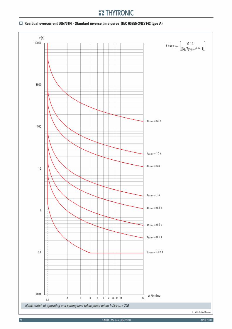
7272 NA011 - Manual - 05 - 2010 APPENDIX
Residual overcurrent 50N/51N - Standard inverse time curve (IEC 60255-3/BS142 type A)
F_51N-IECA-Char.ai
1.12 3 4 5 6 7 8 9 10 20 IE /IE>inv0.01
0.1
1
10
100
1000
10000t [s]
tE>inv = 10 s
tE>inv = 60 s
tE>inv = 5 s
tE>inv = 1 s
tE>inv = 0.5 s
tE>inv = 0.2 s
tE>inv = 0.1 s
tE>inv = 0.02 s
t = tE>inv · [(IE/IE>inv)0.02-1]
0.14
Note: match of operating and setting time takes place when IE/IE>inv = 700
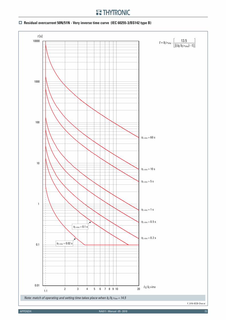
73NA011 - Manual - 05 - 2010APPENDIX
Residual overcurrent 50N/51N - Very inverse time curve (IEC 60255-3/BS142 type B)
F_51N-IECB-Char.ai
1.12 3 4 5 6 7 8 9 10 20 I E/IE>inv0.01
0.1
1
10
100
1000
10000t [s]
tE>inv = 10 s
tE>inv = 60 s
tE>inv = 5 s
tE>inv = 1 s
tE>inv = 0.5 s
tE>inv = 0.2 s
tE>inv = 0.02 s
tE>inv = 0.1 s
t = tE>inv · [(IE/IE>inv) -1]
13.5
Note: match of operating and setting time takes place when IE/IE>inv = 14.5
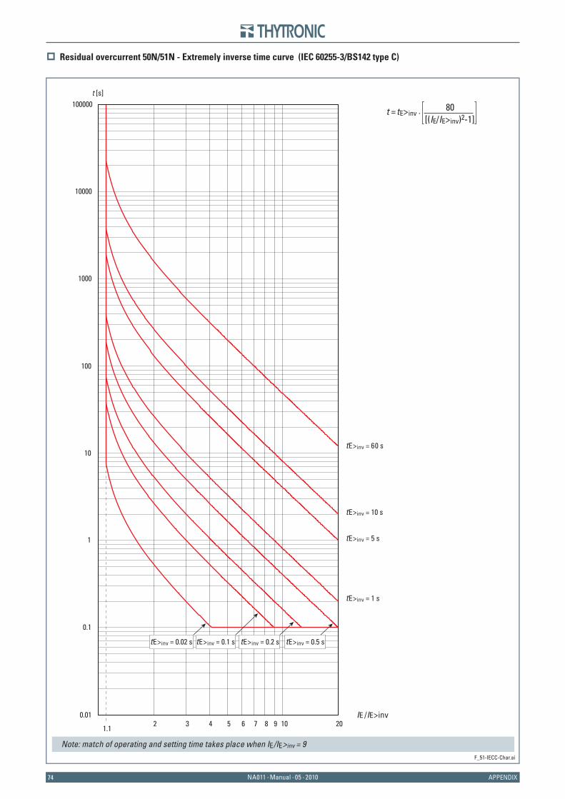
7474 NA011 - Manual - 05 - 2010 APPENDIX
Residual overcurrent 50N/51N - Extremely inverse time curve (IEC 60255-3/BS142 type C)
F_51-IECC-Char.ai
1.12 3 4 5 6 7 8 9 10 20
IE /IE>inv0.01
0.1
1
10
100
1000
10000
100000t [s]
tE>inv = 10 s
tE>inv = 60 s
tE>inv = 5 s
tE>inv = 1 s
tE>inv = 0.5 stE>inv = 0.2 stE>inv = 0.02 s tE>inv = 0.1 s
t = tE>inv · [(IE/IE>inv)2-1]
80
Note: match of operating and setting time takes place when IE/IE>inv = 9
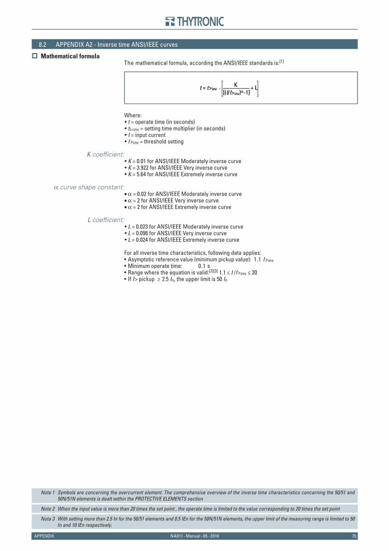
75NA011 - Manual - 05 - 2010APPENDIX
8.2 APPENDIX A2 - Inverse time ANSI/IEEE curves
Mathematical formulaThe mathematical formula, according the ANSI/IEEE standards is:[1]
Where:t = operate time (in seconds)tI>inv = setting time multiplier (in seconds)I = input currentI>inv = threshold setting
K coeffi cient:K = 0.01 for ANSI/IEEE Moderately inverse curveK = 3.922 for ANSI/IEEE Very inverse curveK = 5.64 for ANSI/IEEE Extremely inverse curve
α curve shape constant:α = 0.02 for ANSI/IEEE Moderately inverse curveα = 2 for ANSI/IEEE Very inverse curveα = 2 for ANSI/IEEE Extremely inverse curve
L coeffi cient:L = 0.023 for ANSI/IEEE Moderately inverse curveL = 0.098 for ANSI/IEEE Very inverse curveL = 0.024 for ANSI/IEEE Extremely inverse curve
For all inverse time characteristics, following data applies:Asymptotic reference value (minimum pickup value): 1.1 I>invMinimum operate time: 0.1 sRange where the equation is valid:[2][3] 1.1 ≤ I /I>inv ≤ 20 If I> pickup ≥ 2.5 In, the upper limit is 50 In
Note 1 Symbols are concerning the overcurrent element. The comprehensive overview of the inverse time characteristics concerning the 50/51 and 50N/51N elements is dealt within the PROTECTIVE ELEMENTS section
Note 2 When the input value is more than 20 times the set point , the operate time is limited to the value corresponding to 20 times the set point
Nota 3 With setting more than 2.5 In for the 50/51 elements and 0.5 IEn for the 50N/51N elements, the upper limit of the measuring range is limited to 50 In and 10 IEn respectively.
••••
•••
•••
•••
••••
t = t>inv · [(I/I>inv)α-1]
K + Lt = t>inv · [(I/I>inv)α-1]
K + L
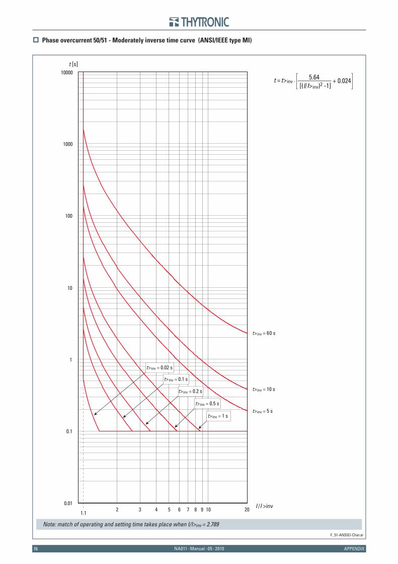
7676 NA011 - Manual - 05 - 2010 APPENDIX
Phase overcurrent 50/51 - Moderately inverse time curve (ANSI/IEEE type MI)
F_51-ANSIEI-Char.ai
1.12 3 4 5 6 7 8 9 10 20 I /I >inv0.01
0.1
1
10
100
1000
10000t [s]
t>inv = 10 s
t>inv = 60 s
t>inv = 5 st>inv = 0.5 s
t>inv = 1 s
t>inv = 0.2 s
t>inv = 0.1 s
t>inv = 0.02 s
t = t>inv · [(I/I>inv)2 -1]
5.64 + 0.024
Note: match of operating and setting time takes place when I/I>inv = 2.789
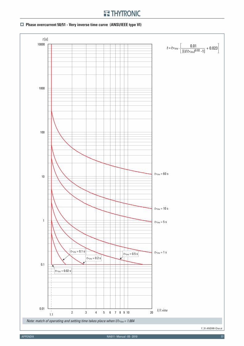
77NA011 - Manual - 05 - 2010APPENDIX
Phase overcurrent 50/51 - Very inverse time curve (ANSI/IEEE type VI)
F_51-ANSIMI-Char.ai
1.12 3 4 5 6 7 8 9 10 20 I /I >inv0.01
0.1
1
10
100
1000
10000t [s]
t>inv = 10 s
t>inv = 60 s
t>inv = 5 s
t>inv = 1 s
t>inv = 0.02 s
t>inv = 0.2 s
t>inv = 0.1 st>inv = 0.5 s
t = t>inv · [(I/I>inv)0.02 -1]
0.01 + 0.023
Note: match of operating and setting time takes place when I/I>inv = 1.664
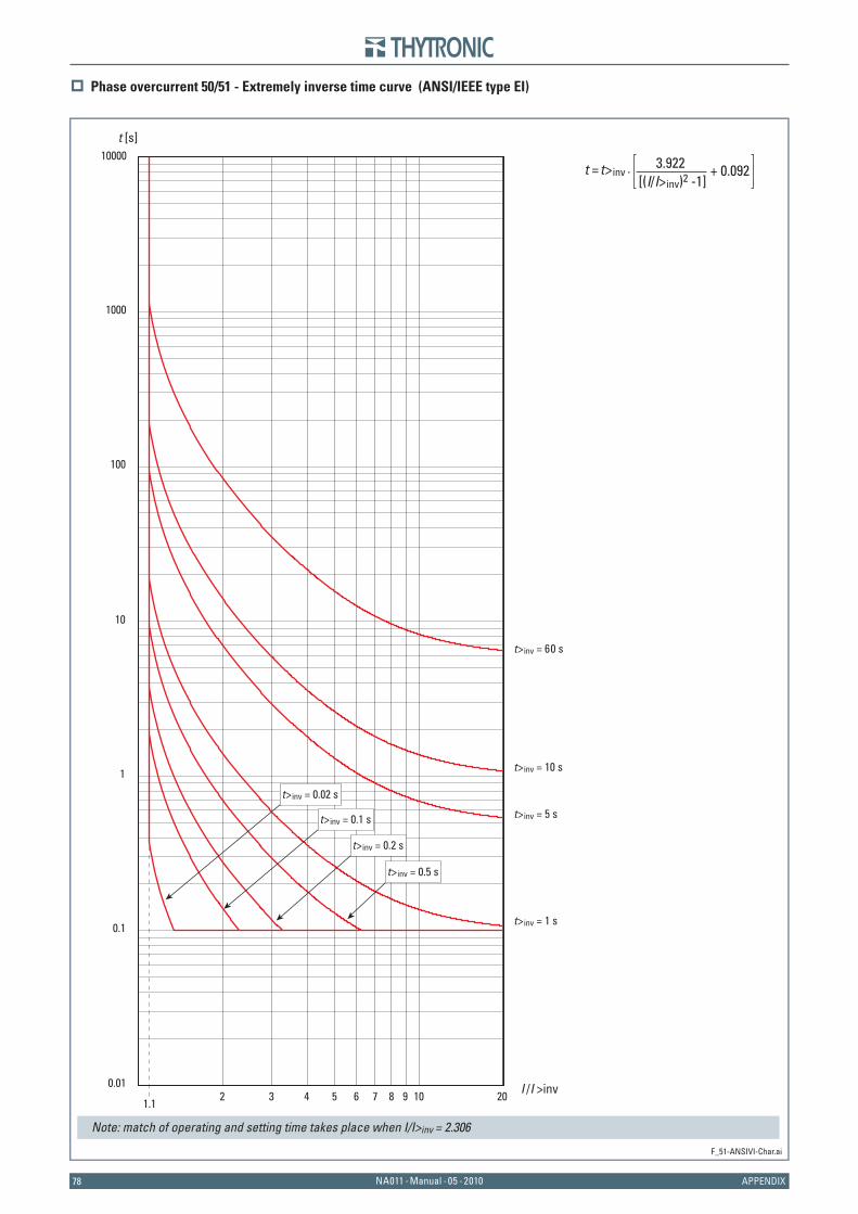
7878 NA011 - Manual - 05 - 2010 APPENDIX
Phase overcurrent 50/51 - Extremely inverse time curve (ANSI/IEEE type EI)
F_51-ANSIVI-Char.ai
1.12 3 4 5 6 7 8 9 10 20 I /I >inv0.01
0.1
1
10
100
1000
10000t [s]
t>inv = 10 s
t>inv = 60 s
t>inv = 5 s
t>inv = 1 s
t>inv = 0.5 s
t>inv = 0.2 s
t>inv = 0.1 s
t>inv = 0.02 s
t = t>inv · [(I/I>inv)2 -1]
3.922 + 0.092
Note: match of operating and setting time takes place when I/I>inv = 2.306
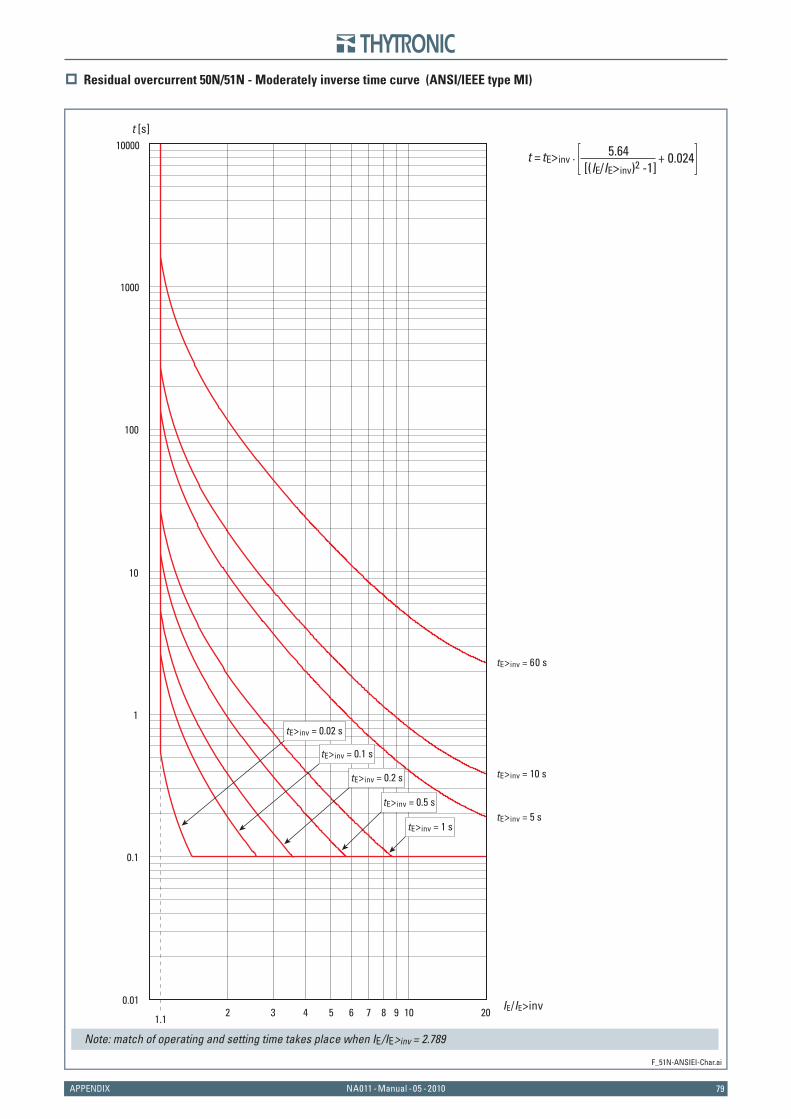
79NA011 - Manual - 05 - 2010APPENDIX
Residual overcurrent 50N/51N - Moderately inverse time curve (ANSI/IEEE type MI)
F_51N-ANSIEI-Char.ai
1.12 3 4 5 6 7 8 9 10 20 IE/IE>inv0.01
0.1
1
10
100
1000
10000t [s]
tE>inv = 10 s
tE>inv = 60 s
tE>inv = 5 stE>inv = 0.5 s
tE>inv = 1 s
tE>inv = 0.2 s
tE>inv = 0.1 s
tE>inv = 0.02 s
t = tE>inv · [(IE/IE>inv)2 -1]
5.64 + 0.024
Note: match of operating and setting time takes place when IE/IE>inv = 2.789
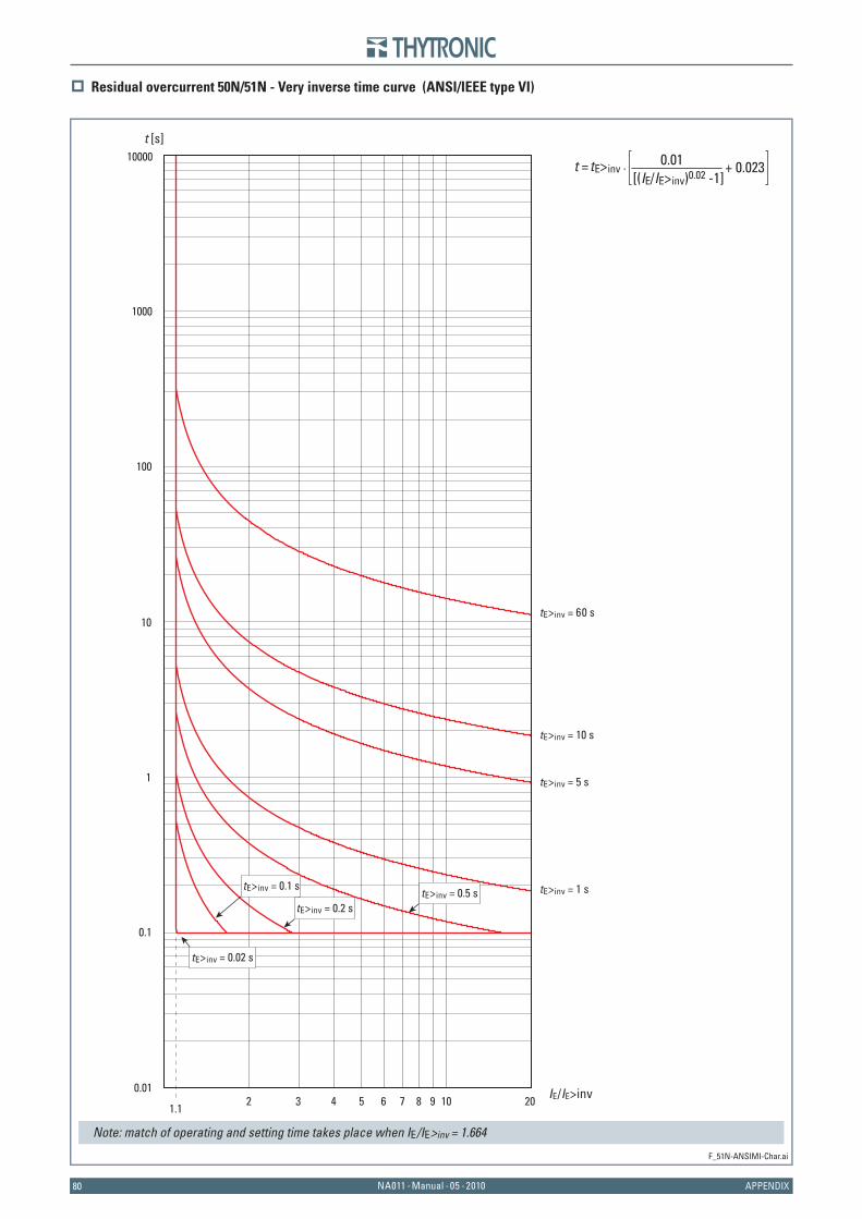
8080 NA011 - Manual - 05 - 2010 APPENDIX
Residual overcurrent 50N/51N - Very inverse time curve (ANSI/IEEE type VI)
F_51N-ANSIMI-Char.ai
1.12 3 4 5 6 7 8 9 10 20 IE/IE>inv0.01
0.1
1
10
100
1000
10000t [s]
tE>inv = 10 s
tE>inv = 60 s
tE>inv = 5 s
tE>inv = 1 s
tE>inv = 0.02 s
tE>inv = 0.2 s
tE>inv = 0.1 stE>inv = 0.5 s
t = tE>inv · [(IE/IE>inv)0.02 -1]
0.01 + 0.023
Note: match of operating and setting time takes place when IE/IE>inv = 1.664
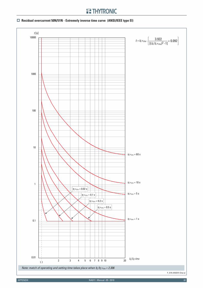
81NA011 - Manual - 05 - 2010APPENDIX
Residual overcurrent 50N/51N - Extremely inverse time curve (ANSI/IEEE type EI)
F_51N-ANSIVI-Char.ai
1.12 3 4 5 6 7 8 9 10 20 IE/IE>inv0.01
0.1
1
10
100
1000
10000t [s]
tE>inv = 10 s
tE>inv = 60 s
tE>inv = 5 s
tE>inv = 1 s
tE>inv = 0.5 s
tE>inv = 0.2 s
tE>inv = 0.1 s
tE>inv = 0.02 s
t = tE>inv · [(IE/IE>inv)2 -1]
3.922 + 0.092
Note: match of operating and setting time takes place when IE/IE>inv = 2.306
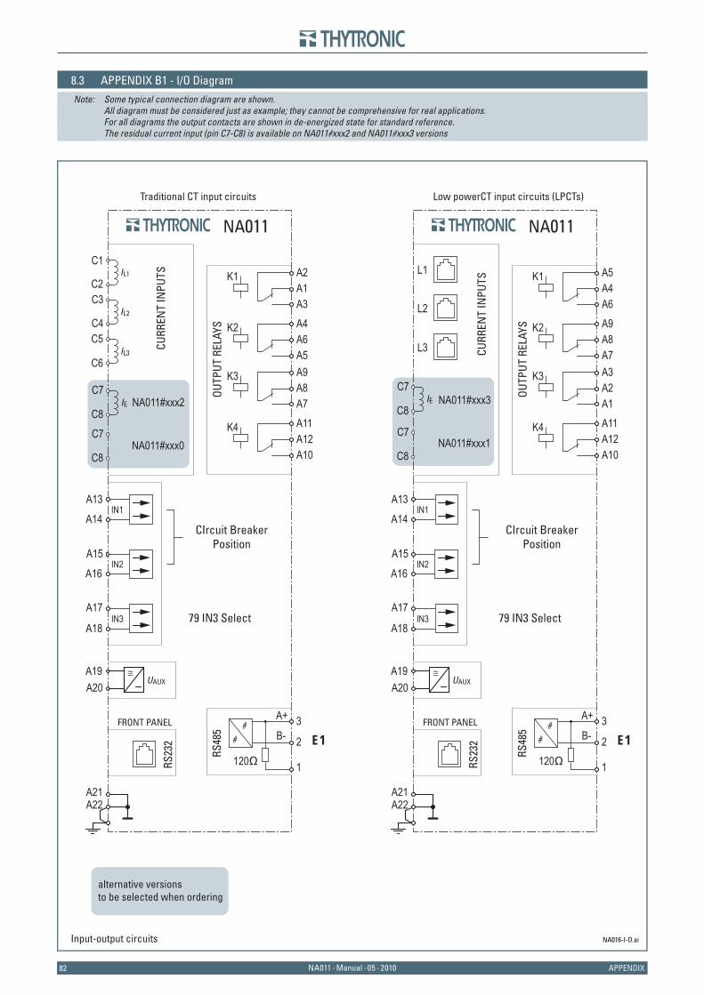
8282 NA011 - Manual - 05 - 2010 APPENDIX
8.3 APPENDIX B1 - I/O DiagramNote: Some typical connection diagram are shown. All diagram must be considered just as example; they cannot be comprehensive for real applications. For all diagrams the output contacts are shown in de-energized state for standard reference. The residual current input (pin C7-C8) is available on NA011#xxx2 and NA011#xxx3 versions
NA016-I-O.aiInput-output circuits
alternative versionsto be selected when ordering
Traditional CT input circuits Low powerCT input circuits (LPCTs)
NA011
C1IL1
IL2
IL3
IE
CURR
ENT
INPU
TS
C2C3
C4C5
C6
C7
C8C7
C8
RS23
2
FRONT PANEL
A13IN1
IN2
IN3
A14
A15
A16
A17
A18
OUTP
UT R
ELAY
S A4A6A5
K2
A2A1A3
K1
A11A12A10
K4
A9A8A7
K3
UAUXA19 ≅
A20
A22A21
B- E1
RS48
5
1
2
3
120Ω
A+
CIrcuit Breaker Position
79 IN3 Select
CIrcuit Breaker Position
79 IN3 Select
NA011
IE
CURR
ENT
INPU
TS
C7
C8
C7
C8RS
232
FRONT PANEL
A13IN1
IN2
IN3
A14
A15
A16
A17
A18
OUTP
UT R
ELAY
S A9A8A7
K2
A5A4A6
K1
A11A12A10
K4
A3A2A1
K3
UAUXA19 ≅
A20
A22A21
B- E1
RS48
5
1
2
3
120Ω
A+
L1
L2
L3
NA011#xxx2
NA011#xxx0
NA011#xxx3
NA011#xxx1

83NA011 - Manual - 05 - 2010APPENDIX
8.4 APPENDIX B2 - Interfaces
Interfaces.ai
NA011
RS23
2
FRONT PANEL
A22A21
B- E1
RS48
5
1
2
3
120Ω
A+
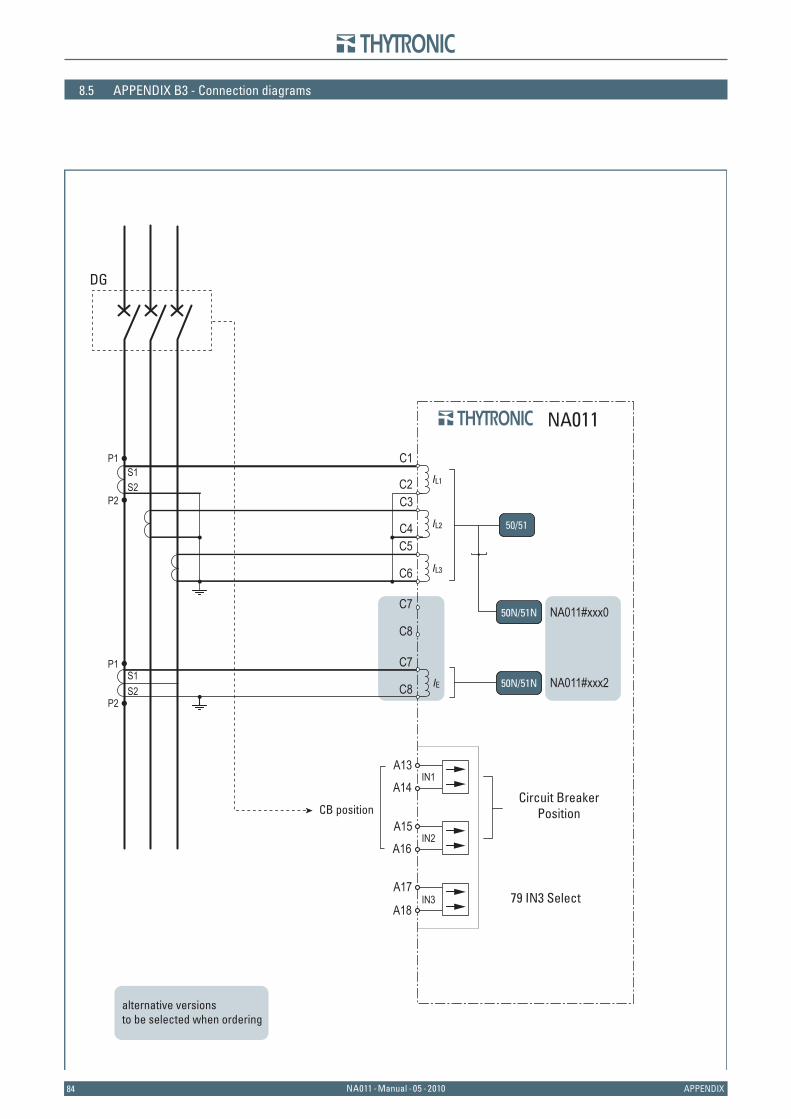
8484 NA011 - Manual - 05 - 2010 APPENDIX
8.5 APPENDIX B3 - Connection diagrams
CB position
NA011
C1IL1
IL2
IL3
P1S1S2
P2C2C3
C4C5
C6
C7
C8
A13IN1
IN2
IN3
A14
A15
A16
A17
A18
DG
C7
C8
IE
P1S1S2
P2
Circuit Breaker Position
79 IN3 Select
NA011#xxx0
NA011#xxx2
50/51
50N/51N
50N/51N
alternative versionsto be selected when ordering
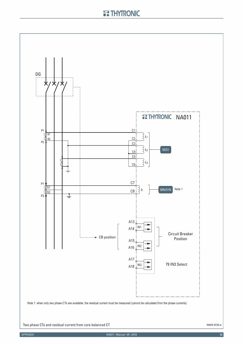
85NA011 - Manual - 05 - 2010APPENDIX
NA016-SCH2.ai
C2
C1
C3
C4C5
C6
P1S1S2
P2
IL1
IL2
IL3
CB position
NA011
A13IN1
IN2
IN3
A14
A15
A16
A17
A18
DG
50/51
IE
P1S1S2
P2
C7
C8 50N/51N
Two phase CTs and residual current from core balanced CT
Circuit Breaker Position
79 IN3 Select
Note 1
Note 1: when only two phase CTs are available, the residual current must be measured (cannot be calculated from the phase currents)
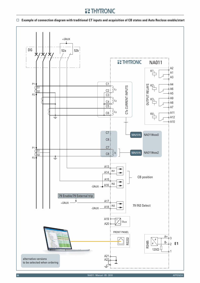
8686 NA011 - Manual - 05 - 2010 APPENDIX
C7
C8
IE
NA011#xxx0
NA011#xxx250N/51N
50N/51N
NA011
P1S1S2
P2
C7
C8
RS23
2
FRONT PANEL
A13IN1
IN2
IN3
A14
A15
A16
A17
A18
OUTP
UT R
ELAY
S A4A6A5
K2
A2A1A3
K1
A11A12A10
K4
A9A8A7
K3
UAUXA19 ≅
A20
A22A21
B- E1
RS48
5
1
2
3
120Ω
A+
DG 52a 52b
-UAUX
-UAUX
+UAUX
+UAUX
C1IL1
IL2
IL3 CTs
CURR
ENT
INPU
TS
P1S1S2
P2C2C3
C4C5
C6
79 IN3 Select
79 Enable/79 External trip
CB position
alternative versionsto be selected when ordering
Example of connection diagram with traditional CT inputs and acquisition of CB states and Auto Reclose enable/start
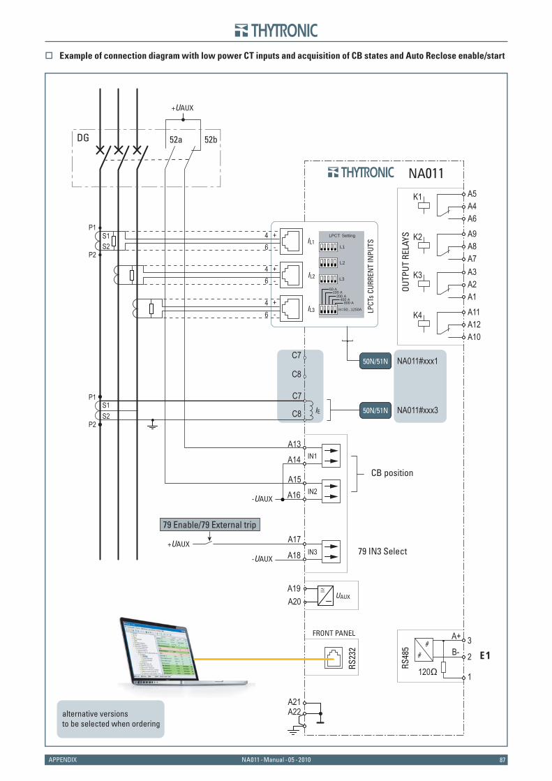
87NA011 - Manual - 05 - 2010APPENDIX
C7
C8
IE
NA011#xxx1
NA011#xxx350N/51N
50N/51N L
PCTs
CUR
REN
T IN
PUTSIL1
IL2
IL3
P1
46
+-
46
+-
46
+-
P2
S1S2 L1
L2
SettingLPCT
800 A400 A
200 A100 A
50 A
L3
In=50...1250A
NA011
P1S1S2
P2
C7
C8
RS23
2
FRONT PANEL
A13IN1
IN2
IN3
A14
A15
A16
A17
A18
UAUXA19 ≅
A20
A22A21
B- E1
RS48
5
1
2
3
120Ω
A+
DG 52a 52b
-UAUX
-UAUX
+UAUX
+UAUX
79 IN3 Select
79 Enable/79 External trip
CB position
OUTP
UT R
ELAY
S A9A8A7
K2
A5A4A6
K1
A11A12A10
K4
A3A2A1
K3
alternative versionsto be selected when ordering
Example of connection diagram with low power CT inputs and acquisition of CB states and Auto Reclose enable/start
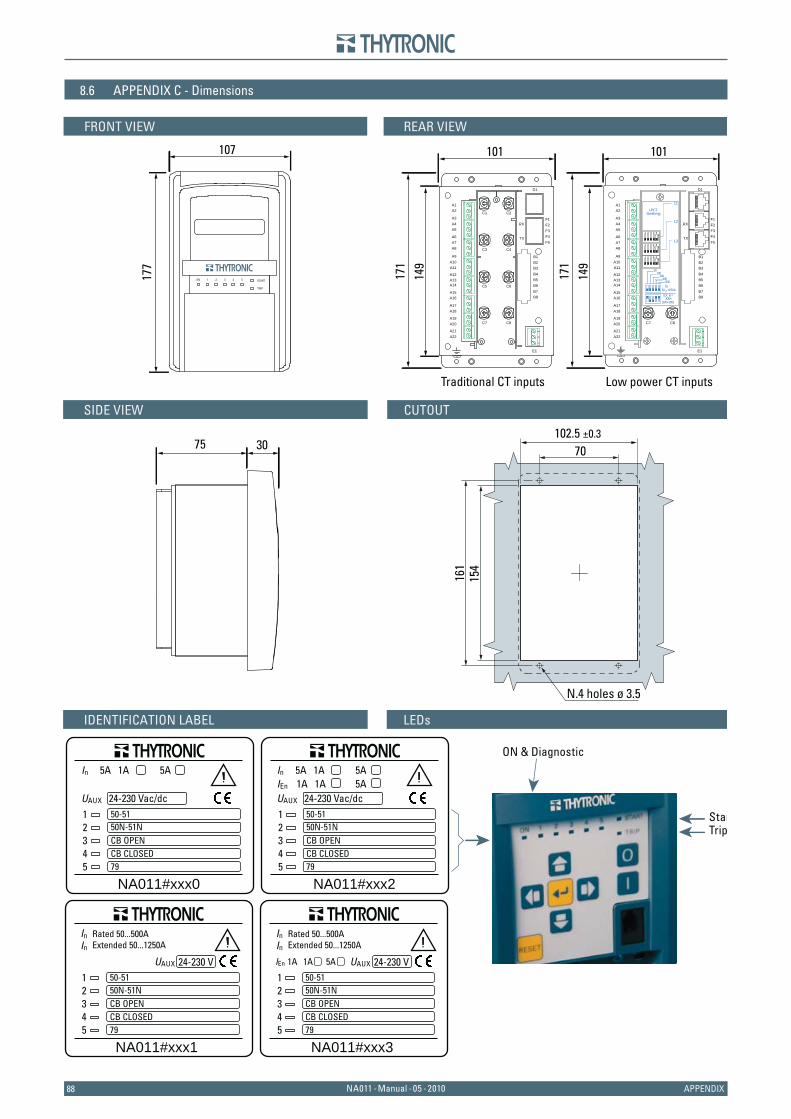
8888 NA011 - Manual - 05 - 2010 APPENDIX
8.6 APPENDIX C - Dimensions
75 30
10717
7
102.5 ±0.3
7016
115
4
SIDE VIEW CUTOUT
FRONT VIEW
ON 41 32 5
TRIP
START
REAR VIEW
IDENTIFICATION LABEL LEDs
Traditional CT inputs Low power CT inputs
N.4 holes ø 3.5
ON & Diagnostic
StarTrip
NA011#xxx0
In 5A 1A
50-5150N-51NCB OPENCB CLOSED79
5A
UAUX 24-230 Vac/dc12345
NA011#xxx1
IIn
n
Rated 50...500AExtended 50...1250A
50-5150N-51NCB OPENCB CLOSED79
UAUX 24-230 V12345
NA011#xxx2
In 5A 1A
50-5150N-51NCB OPENCB CLOSED79
5A
UAUX 24-230 Vac/dcIEn 1A 1A 5A
12345
NA011#xxx3
IIn
n
Rated 50...500AExtended 50...1250A
50-5150N-51NCB OPENCB CLOSED79
IEn 1A 1A 5A UAUX 24-230 V12345
101
171
149
101
171
149
F1
D1
RX
TX
F2F3F4F5
A1A2
A3A4A5
A6A7A8
A9A10A11
A12A13A14
A15A16
A17A18
A19A20
A21A22
B1B2B3B4B5B6B7B8
C1 C2
C4C3
C5 C6
C7 C8 C7 C8
E1
F1
D1
RX
TX
F2F3F4F5
A1A2
A3A4A5
A6A7A8
A9A10A11
A12A13A14
A15A16
A17A18
A19A20
A21A22
B1B2B3B4B5B6B7B8
E1
31
2
31
2
LPCTSetting
(100+200)300A
EX. In=
50
200400
100
800
L3
L2
L1
1 2 3 4 5
1 2 3 4 5
1 2 3 4 5
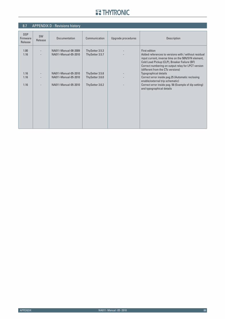
89NA011 - Manual - 05 - 2010APPENDIX
8.7 APPENDIX D - Revisions history
DSPFirmwareRelease
SWRelease
Documentation Communication Upgrade procedures Description
1.001.16
1.161.16
1.16
--
--
-
NA011-Manual-08-2009NA011-Manual-05-2010
NA011-Manual-05-2010NA011-Manual-05-2010
NA011-Manual-05-2010
ThySetter 3.5.3ThySetter 3.5.7
ThySetter 3.5.8ThySetter 3.6.0
ThySetter 3.6.2
--
--
-
First editionAdded references to versions with / without residual input current, inverse time on the 50N/51N element, Cold Load Pickup (CLP), Breaker Failure (BF)Correct numbering on output relay for LPCT version (different from the CTs versions)Typographical detailsCorrect error inside pag.25 (Automatic reclosing enable/external trip schematic)Correct error inside pag. 56 (Example of dip setting) and typographical details
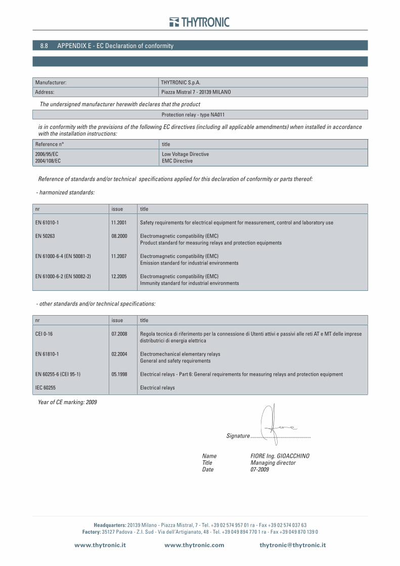
Headquarters: 20139 Milano - Piazza Mistral, 7 - Tel. +39 02 574 957 01 ra - Fax +39 02 574 037 63Factory: 35127 Padova - Z.I. Sud - Via dell’Artigianato, 48 - Tel. +39 049 894 770 1 ra - Fax +39 049 870 139 0
www.thytronic.it www.thytronic.com [email protected]
8.8 APPENDIX E - EC Declaration of conformity
Manufacturer: THYTRONIC S.p.A.
Address: Piazza Mistral 7 - 20139 MILANO
The undersigned manufacturer herewith declares that the product
Protection relay - type NA011
is in conformity with the previsions of the following EC directives (including all applicable amendments) when installed in accordance with the installation instructions:
Reference n° title
2006/95/EC2004/108/EC
Low Voltage DirectiveEMC Directive
Reference of standards and/or technical specifi cations applied for this declaration of conformity or parts thereof:
- harmonized standards:
nr issue title
EN 61010-1
EN 50263
EN 61000-6-4 (EN 50081-2)
EN 61000-6-2 (EN 50082-2)
11.2001
08.2000
11.2007
12.2005
Safety requirements for electrical equipment for measurement, control and laboratory use
Electromagnetic compatibility (EMC)Product standard for measuring relays and protection equipments
Electromagnetic compatibility (EMC)Emission standard for industrial environments
Electromagnetic compatibility (EMC)Immunity standard for industrial environments
- other standards and/or technical specifi cations:
nr issue title
CEI 0-16
EN 61810-1
EN 60255-6 (CEI 95-1)
IEC 60255
07.2008
02.2004
05.1998
Regola tecnica di riferimento per la connessione di Utenti attivi e passivi alle reti AT e MT delle imprese distributrici di energia elettrica
Electromechanical elementary relaysGeneral and safety requirements
Electrical relays - Part 6: General requirements for measuring relays and protection equipment
Electrical relays
Year of CE marking: 2009
Signature ............................................. Name FIORE Ing. GIOACCHINO Title Managing director Date 07-2009