manual - advantechadvdownload.advantech.com › productfile › downloadfile4 › 1-p70c6 … ·...
TRANSCRIPT
ADAM CPU 8517PCI Content
HB105E - Rev. 02/14 1
Manual
ADAM CPU 8517PCI
Order No.: ADAM HB105E Rev. 02/14
PCI Slot CPUADAM-8517 1BM00
Revision 1.1

ADAM CPU 8517PCI Content
2 ADAM 8000 manual Slot -CPU - Rev. 1.1
The information contained in this manual is supplied without warranties. Information is subject to change without notice. © Copyright 2002 Advantech Co., Ltd.
No. 1 Alley 20, Lane 2, Rueiguang Rd., Neihu District, Taipei, Taiwan 114, R.O.C.
EMail: [email protected] http://www.advantech.com All rights reserved
The contents of this manual was carefully examined to ensure that it conforms with the described hardware and software. However, discrepancies can not be avoided. The specifications in this manual are examined regularly and corrections will be included in subsequent editions. We gratefully accept suggestions for improvement.
ADAM is a registered trademark of Advantech Co., Ltd.
STEP is a registered trademark of Siemens AG.
Any other trade marks referred to in the text are the trademarks of the respective owner and we acknowledge their registration.
Disclaimer of liability
Trademarks
ADAM CPU 8517PCI Content
ADAM 8000 manual Slot -CPU - Rev. 1.1 3
Content
This product supplement contains all information required for the deployment of the Slot-PLC CPU 8517 PCI in your PC. The here described Slot-PLC is a CPU 8517 with integrated Profibus-DP master.
Topic Page Contents ....................................................................................................3 System overview........................................................................................4 Structure ....................................................................................................6 Components ..............................................................................................7 Deployment PLC-CPU.............................................................................10 Deployment Profibus-DP master .............................................................15 Deployment of the MMC..........................................................................20 Commissioning and Start-up behavior.....................................................22 Technical Data.........................................................................................23
Type Order number Description CPU 8517PCI ADAM-8517-1BM00 CPU 8517PCI with Profibus-DP masterMMC ADAM-8953-0KX00 MMC storage module USB-MMC reading device
ADAM-8950-0AD00 USB adapter for MMC programming
Green Cable ADAM-8950-0KB00 PC/AG download cable WinPLC7 ADAM WinPLC7 Programming tool WinNCS ADAM SW-WinNCS Parameterization software for Profibus-
DP under Win95/98/NT/2000 OPC-Server ADAM SW860M Driver license for MPI
included with CPU 8517 ADAM SW860T Driver license for TCP/IP (read/write)
Outline
Content
Order data
ADAM CPU 8517PCI System overview
4 ADAM 8000 manual Slot -CPU - Rev. 1.1
System overview
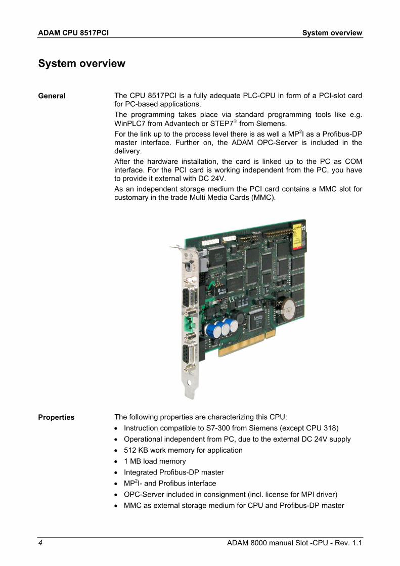
The CPU 8517PCI is a fully adequate PLC-CPU in form of a PCI-slot card for PC-based applications. The programming takes place via standard programming tools like e.g. WinPLC7 from Advantech or STEP7 from Siemens. For the link up to the process level there is as well a MP2I as a Profibus-DP master interface. Further on, the ADAM OPC-Server is included in the delivery. After the hardware installation, the card is linked up to the PC as COM interface. For the PCI card is working independent from the PC, you have to provide it external with DC 24V. As an independent storage medium the PCI card contains a MMC slot for customary in the trade Multi Media Cards (MMC).
The following properties are characterizing this CPU: • Instruction compatible to S7-300 from Siemens (except CPU 318) • Operational independent from PC, due to the external DC 24V supply • 512 KB work memory for application • 1 MB load memory • Integrated Profibus-DP master • MP2I- and Profibus interface • OPC-Server included in consignment (incl. license for MPI driver) • MMC as external storage medium for CPU and Profibus-DP master
General
Properties
ADAM CPU 8517PCI System overview
ADAM 8000 manual Slot -CPU - Rev. 1.1 5
The Slot-PLC 8517PCI is instruction compatible to STEP®7 from Siemens and may be programmed via the STEP®7 manager from Siemens. An extensive function library is included in the consignment.
For the link up to Profibus, the CPU includes a Profibus-DP master. During the operation the DP master overlays an adjustable address area in the CPU with its own data areas. The address range is configured in your projecting tool (e.g. WinNCS from Advantech or hardware configurator from Siemens).
The project engineering of the Profibus-DP master may be done under WinNCS from Advantech or in the hardware configurator from Siemens. After the hardware installation incl. driver, the Slot-PLC is linked up as COM interface. Via this interface you may access the CPU and the Profibus-DP master. This allows an easy data exchange with the normal programming tools on your PC. For accesses on the Profibus-DP master from an external PC, the MP2I interface is at your disposal.
The Slot-PLC provides 2 MPInterfaces: The 1st is led out as MP2I adapter. Additionally to the MPI functionality it also provides the possibility for a point-to-point connection via the "Green Cable" from Advantech. The 2nd MPI adapter is available as virtual COM interface in the PC. For this you will find an according driver in the consignment, that must be included in the PCI card installation.
For operating the CPU via the PC the program "PLC-Tool" is included in the consignment. For monitoring and operating of the CPU, your PC shows an user interface that is modeled on the schematic view on a CPU front. Via the PLC-Tool you may request the LED state and monitor resp. change the operating mode of the CPU.
CPU and Profibus-DP master are both using the Multi Media Card (MMC) as external storage medium, independent from the PC. For the installation and dismantling of the MMC you have to open the PC. The MMC is available at Advantech.
The CPU has an integrated power supply, that has to be provided with DC 24V via the frontside. The power supply is protected against polarity inversion and overcurrent. Due to the external voltage supply, you may operate your Slot-PLC card independent from the PC.
Instruction compatibility
Profibus-DP master section
Project engineering of the DP master
MPInterface
Operating options via PLC-Tool
Multi Media Card as external storage medium
Integrated power supply
ADAM CPU 8517PCI Structure
6 ADAM 8000 manual Slot -CPU - Rev. 1.1
Structure
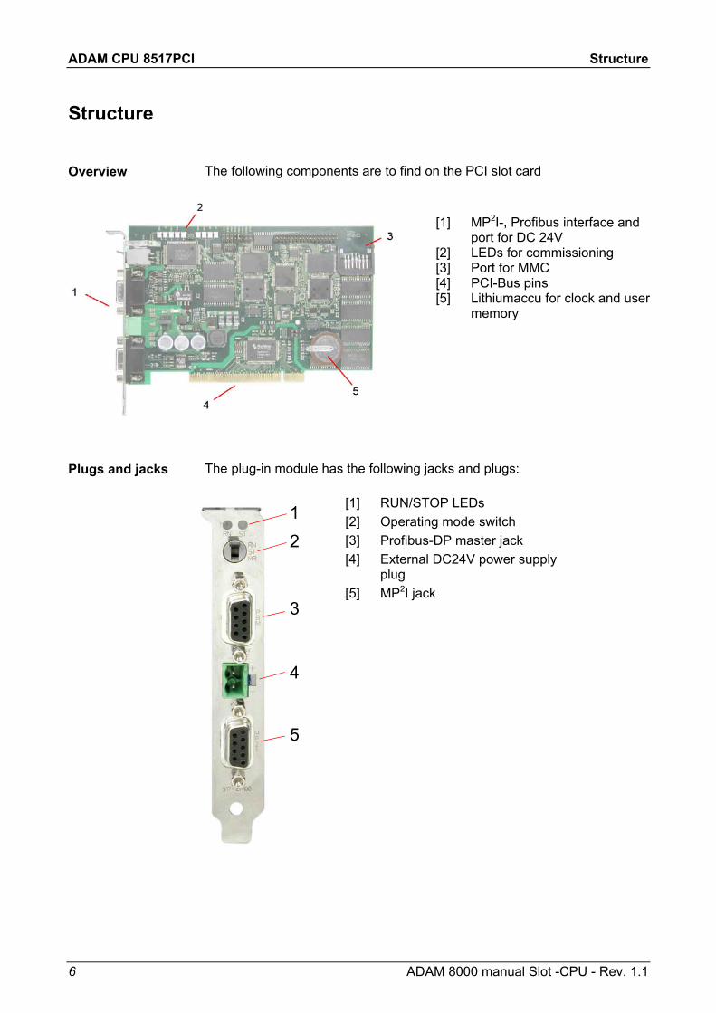
The following components are to find on the PCI slot card
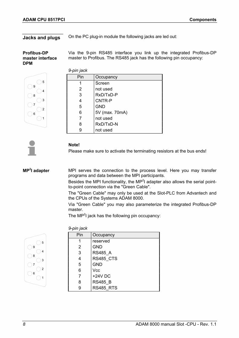
The plug-in module has the following jacks and plugs:
Overview
Plugs and jacks
[1] MP2I-, Profibus interface and port for DC 24V
[2] LEDs for commissioning [3] Port for MMC [4] PCI-Bus pins [5] Lithiumaccu for clock and user
memory
[1] RUN/STOP LEDs [2] Operating mode switch [3] Profibus-DP master jack [4] External DC24V power supply
plug [5] MP2I jack
2
3
4
5
1

ADAM CPU 8517PCI Components
ADAM 8000 manual Slot -CPU - Rev. 1.1 7
Components
On the plug-in module you can see a LED bar for status monitoring of the CPU and the Profibus-DP master. Especially at the commissioning and the external usage of the module, the state of your CPU and your Profibus-DP master is shown. At deployment inside a PC, you may issue the state of the LEDs on your PC via the delivered software PLC-Tool. The usage and the according colors of the LEDs are to see in the following tables: CPU section
Label Color Description The upper LED is not addressed
MMC red blinks at MMC access FRCE yellow blinks as soon as variable are forced (fixed)
SF red blinks at system errors (hardware defect) PWR yellow CPU section is provided internal with 5V
Note! All LEDs of the CPU sections are blinking for three times at access on an invalid MMC or if the MMC is pulled out during reading. Profibus-DP master section
Label Color Description IF red Initialization error at wrong parameterization DE yellow DE (Data exchange) shows communication via
Profibus. ERR red blinks at slave break-down RUN green If only RUN blinks, the DP master is in RUN. The
slaves are addressed and the outputs are 0 ("clear"-state). If RUN+DE are on, the DP-Master is in "operate"-state (Data exchange with the slaves).
Above the operating mode lever there are 2 LEDs, showing the operating state:
Label Color Description STOP red CPU is in STOP RUN green CPU is in RUN
LED bar
LEDs at connection panel
ADAM CPU 8517PCI Components
8 ADAM 8000 manual Slot -CPU - Rev. 1.1
On the PC plug-in module the following jacks are led out:
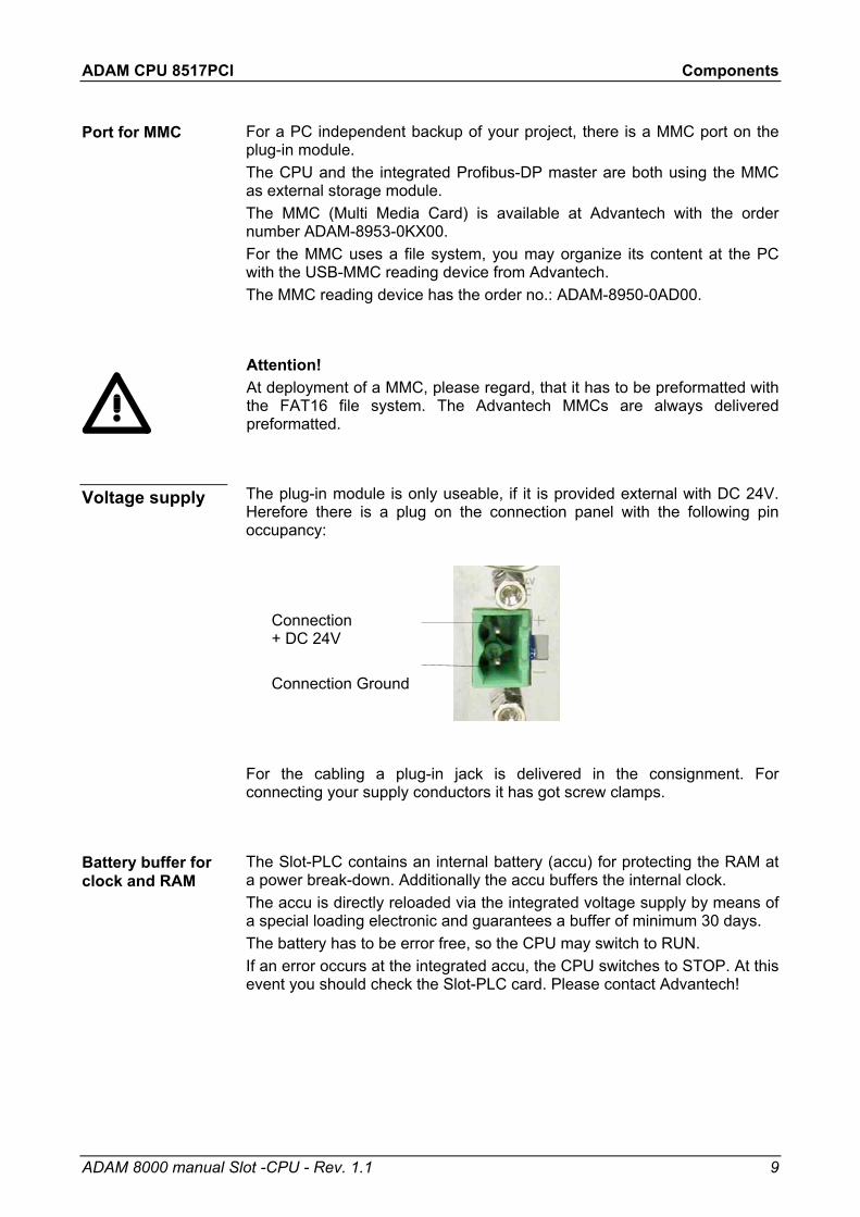
Via the 9-pin RS485 interface you link up the integrated Profibus-DP master to Profibus. The RS485 jack has the following pin occupancy: 9-pin jack
Pin Occupancy 1 Screen 2 not used 3 RxD/TxD-P 4 CNTR-P 5 GND 6 5V (max. 70mA) 7 not used 8 RxD/TxD-N 9 not used
Note! Please make sure to activate the terminating resistors at the bus ends!
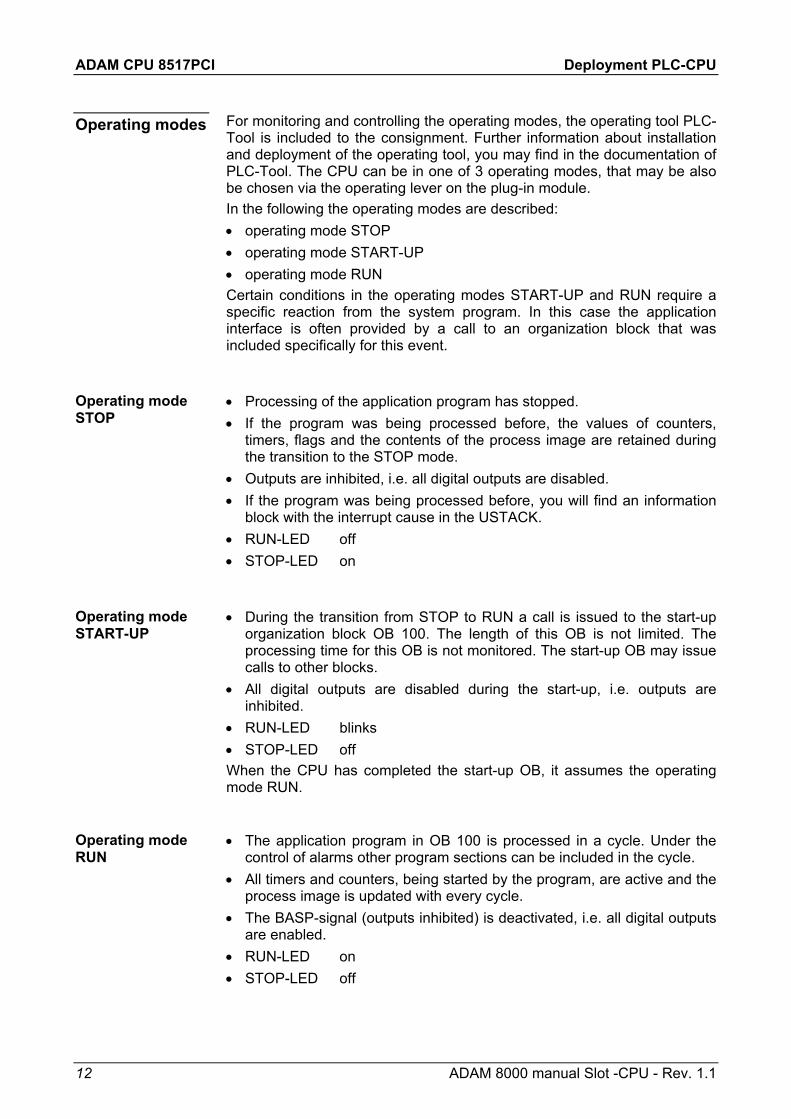
MPI serves the connection to the process level. Here you may transfer programs and data between the MPI participants. Besides the MPI functionality, the MP2I adapter also allows the serial point-to-point connection via the "Green Cable". The "Green Cable" may only be used at the Slot-PLC from Advantech and the CPUs of the Systems ADAM 8000. Via "Green Cable" you may also parameterize the integrated Profibus-DP master. The MP2I jack has the following pin occupancy: 9-pin jack
Pin Occupancy 1 reserved 2 GND 3 RS485_A 4 RS485_CTS 5 GND 6 Vcc 7 +24V DC 8 RS485_B 9 RS485_RTS
Jacks and plugs
Profibus-DP master interface DPM
MP2I adapter
5
4
3
2
1
9
8
7
6
5
4
3
2
1
9
8
7
6
ADAM CPU 8517PCI Components
ADAM 8000 manual Slot -CPU - Rev. 1.1 9
For a PC independent backup of your project, there is a MMC port on the plug-in module. The CPU and the integrated Profibus-DP master are both using the MMC as external storage module. The MMC (Multi Media Card) is available at Advantech with the order number ADAM-8953-0KX00. For the MMC uses a file system, you may organize its content at the PC with the USB-MMC reading device from Advantech. The MMC reading device has the order no.: ADAM-8950-0AD00.
Attention! At deployment of a MMC, please regard, that it has to be preformatted with the FAT16 file system. The Advantech MMCs are always delivered preformatted.
The plug-in module is only useable, if it is provided external with DC 24V. Herefore there is a plug on the connection panel with the following pin occupancy:
Connection + DC 24V
Connection Ground
For the cabling a plug-in jack is delivered in the consignment. For connecting your supply conductors it has got screw clamps.
The Slot-PLC contains an internal battery (accu) for protecting the RAM at a power break-down. Additionally the accu buffers the internal clock. The accu is directly reloaded via the integrated voltage supply by means of a special loading electronic and guarantees a buffer of minimum 30 days. The battery has to be error free, so the CPU may switch to RUN. If an error occurs at the integrated accu, the CPU switches to STOP. At this event you should check the Slot-PLC card. Please contact Advantech!
Port for MMC
Voltage supply
Battery buffer for clock and RAM

ADAM CPU 8517PCI Deployment PLC-CPU
10 ADAM 8000 manual Slot -CPU - Rev. 1.1
Deployment PLC-CPU
The CPU is instruction set compatible to STEP7 from Siemens. The access from the programming interface of the PC on the CPU resp. on the Profibus-DP master happens via a virtual COM interface, that is provided from a driver. For controlling the CPU there is a comfortable user program in the consignment, which shows the operating modes on the desktop and allows the setting of the operating modes RUN and STOP and the OVERALL_RESET. These settings may be also made by the integrated operating mode lever. Via the integrated MP2I and Profibus interface, you establish the connection to the process level. If your programming package is on an external PC, you may access the CPU and the Profibus-DP master via MP2I.
Note! The project engineering of the CPU requires a thorough knowledge of the Siemens STEP7 configuration tools! The periphery area from ADAM covers an address range from 0 to 255. Out of that, the addresses from 0 to 127 are assigned to the process image.
The CPU does not use all parameters that you may define in your projecting tool. The following parameters are exploited at that time: General:
MPI address of the CPU maximum MPI address
Start-up:
Start-up at scheduled configura-tion unequal effective config.
Remanence:
No. of bit mem. bytes from MB0 No. of S7-timers from T0
No. of S7-counters from Z0
Time alarm : OB10: active execution start date time-of-day
Prompter alarm :
OB35: execution Cycle / pulse bit memory:
Cycle watching time Cycle load due to communications
Timing flags with flag byte no.
Outline
Restricted use of CPU parameters

ADAM CPU 8517PCI Deployment PLC-CPU
ADAM 8000 manual Slot -CPU - Rev. 1.1 11
As soon as the PC-plug-in module is built in and the according driver has been installed, the plug-in module is linked up as virtual COM interface. By selecting the COM interface in your programming resp. parameterization tool, you gain internal access to the CPU and the Profibus master. Additionally there is a 2nd MPI at your disposal via the external MP2I jack.
The data transfer is managed via MPI. If your programming unit (PU) has no MPI port, you may use the Advantech "Green Cable" to establish a serial point-to-point connection from your PC to MPI. The "Green Cable" has the order no. ADAM-8950-0KB00 and may only be used with the ADAM CPU 8517PCI and the CPUs of the System 8000. • Connect your PU with the CPU • Via PLC > Load to module in your projecting tool you transfer the project
into the CPU.
As external storage medium a Multi Media Card (MMC) is deployed. The MMC is available from Advantech and has the order no. ADAM-8953-0KX00. The MMC is delivered preformatted. The MMC slot is located on the plug-in module. For plugging the MMC in or pulling it out, you have to open the PC.
Transfer CPU → MMC When the MMC is plugged-in, the application program is stored on the MMC via a write command. This is controlled by means of the Siemens STEP7 Manager via PLC > Copy RAM to ROM. During the write process the red "MMC"-LED of the CPU is blinking.
Transfer MMC → CPU The transfer of the application program from the MMC into the CPU takes always place after an OVERALL_RESET. The blinking of the red LED "MMC" of the CPU marks the active transfer. If there is no valid application program on the MMC or if the transfer should fail, the CPU switches to STOP and the red "STOP"-LED blinks three times.
Note! You must remember that the memory size has been tailored to the CPU! If the application program is larger than the memory available on the CPU, the content of the MMC is not transferred into the CPU. It is advisable to compress the application program before transferring it into the MMC. This doesn't happen automatically. When deploying a MMC, please make sure that it is preformatted.
Internal project transfer
External project transfer
Usage of the MMC
ADAM CPU 8517PCI Deployment PLC-CPU
12 ADAM 8000 manual Slot -CPU - Rev. 1.1
For monitoring and controlling the operating modes, the operating tool PLC-Tool is included to the consignment. Further information about installation and deployment of the operating tool, you may find in the documentation of PLC-Tool. The CPU can be in one of 3 operating modes, that may be also be chosen via the operating lever on the plug-in module. In the following the operating modes are described: • operating mode STOP • operating mode START-UP • operating mode RUN Certain conditions in the operating modes START-UP and RUN require a specific reaction from the system program. In this case the application interface is often provided by a call to an organization block that was included specifically for this event.
• Processing of the application program has stopped. • If the program was being processed before, the values of counters,
timers, flags and the contents of the process image are retained during the transition to the STOP mode.
• Outputs are inhibited, i.e. all digital outputs are disabled. • If the program was being processed before, you will find an information
block with the interrupt cause in the USTACK. • RUN-LED off • STOP-LED on
• During the transition from STOP to RUN a call is issued to the start-up organization block OB 100. The length of this OB is not limited. The processing time for this OB is not monitored. The start-up OB may issue calls to other blocks.
• All digital outputs are disabled during the start-up, i.e. outputs are inhibited.
• RUN-LED blinks • STOP-LED off When the CPU has completed the start-up OB, it assumes the operating mode RUN.
• The application program in OB 100 is processed in a cycle. Under the
control of alarms other program sections can be included in the cycle. • All timers and counters, being started by the program, are active and the
process image is updated with every cycle. • The BASP-signal (outputs inhibited) is deactivated, i.e. all digital outputs
are enabled. • RUN-LED on • STOP-LED off
Operating modes
Operating mode STOP
Operating mode START-UP
Operating mode RUN

ADAM CPU 8517PCI
ADAM 8000 manual Slot -CPU - Rev. 1.1 13
During the OVERALL_RESET the entire user memory (RAM) and the remanent memory area is erased. Data located in the memory card is not affected. You should always issue an overall reset to your CPU before loading an application program into your CPU, to ensure that all blocks have been cleared from it.
Condition The operating mode of the CPU is STOP. Place the function selector on the CPU in position "STOP" → The ST-LED is on. OVERALL_RESET • Place the function selector in the position MR and hold it in this position
for app. 3 seconds. → The ST-LED changes from blinking to permanently on.
• Place the function selector in the position STOP and switch it to MR and quickly back to STOP within a period of less than 3 seconds. → The ST-LED blinks (overall reset procedure).
• The overall_reset has been completed when the STOP-LED is on permanently. → The ST-LED is on.
The following figure illustrates the above procedure:
3 Sec.
3 Sec.
RN
ST
MR
RN
ST
MR
RN
ST
MR
RN
ST
MR
1 2 3 4
RN ST RN ST RN STRN ST
Overall_Reset
Outline
OVERALL_RESET by means of the function selector
ADAM CPU 8517PCI
14 ADAM 8000 manual Slot -CPU - Rev. 1.1
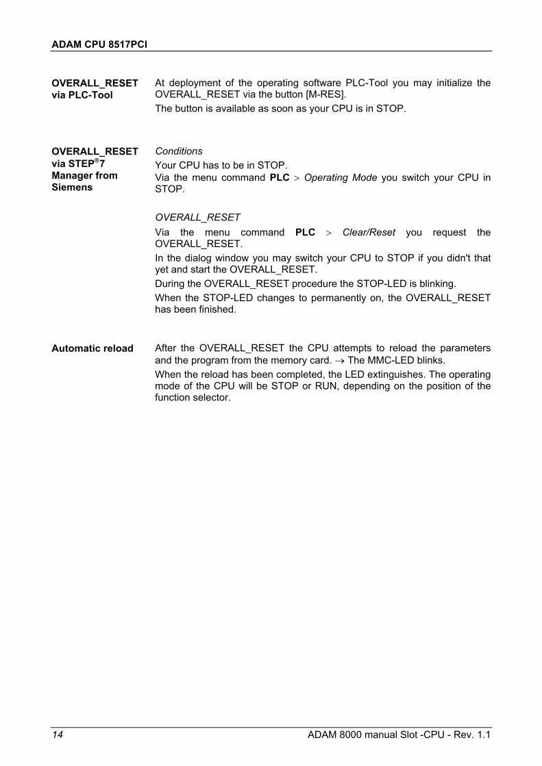
At deployment of the operating software PLC-Tool you may initialize the OVERALL_RESET via the button [M-RES]. The button is available as soon as your CPU is in STOP. Conditions Your CPU has to be in STOP. Via the menu command PLC > Operating Mode you switch your CPU in STOP. OVERALL_RESET Via the menu command PLC > Clear/Reset you request the OVERALL_RESET. In the dialog window you may switch your CPU to STOP if you didn't that yet and start the OVERALL_RESET. During the OVERALL_RESET procedure the STOP-LED is blinking. When the STOP-LED changes to permanently on, the OVERALL_RESET has been finished.
After the OVERALL_RESET the CPU attempts to reload the parameters and the program from the memory card. → The MMC-LED blinks. When the reload has been completed, the LED extinguishes. The operating mode of the CPU will be STOP or RUN, depending on the position of the function selector.
OVERALL_RESET via PLC-Tool
OVERALL_RESET via STEP7 Manager from Siemens
Automatic reload
ADAM CPU 8517PCI Deployment Profibus-DP master
ADAM 8000 manual Slot -CPU - Rev. 1.1 15
Deployment Profibus-DP master
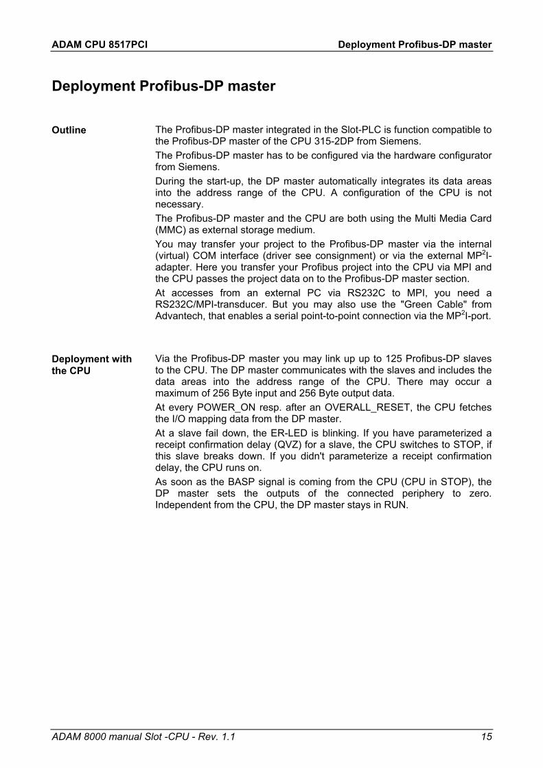
The Profibus-DP master integrated in the Slot-PLC is function compatible to the Profibus-DP master of the CPU 315-2DP from Siemens. The Profibus-DP master has to be configured via the hardware configurator from Siemens. During the start-up, the DP master automatically integrates its data areas into the address range of the CPU. A configuration of the CPU is not necessary. The Profibus-DP master and the CPU are both using the Multi Media Card (MMC) as external storage medium. You may transfer your project to the Profibus-DP master via the internal (virtual) COM interface (driver see consignment) or via the external MP2I-adapter. Here you transfer your Profibus project into the CPU via MPI and the CPU passes the project data on to the Profibus-DP master section. At accesses from an external PC via RS232C to MPI, you need a RS232C/MPI-transducer. But you may also use the "Green Cable" from Advantech, that enables a serial point-to-point connection via the MP2I-port. Via the Profibus-DP master you may link up up to 125 Profibus-DP slaves to the CPU. The DP master communicates with the slaves and includes the data areas into the address range of the CPU. There may occur a maximum of 256 Byte input and 256 Byte output data. At every POWER_ON resp. after an OVERALL_RESET, the CPU fetches the I/O mapping data from the DP master. At a slave fail down, the ER-LED is blinking. If you have parameterized a receipt confirmation delay (QVZ) for a slave, the CPU switches to STOP, if this slave breaks down. If you didn't parameterize a receipt confirmation delay, the CPU runs on. As soon as the BASP signal is coming from the CPU (CPU in STOP), the DP master sets the outputs of the connected periphery to zero. Independent from the CPU, the DP master stays in RUN.
Outline
Deployment with the CPU

ADAM CPU 8517PCI Deployment Profibus-DP master
16 ADAM 8000 manual Slot -CPU - Rev. 1.1
For the project engineering of the Profibus-DP master you have to deploy the hardware manager from Siemens. Your Profibus projects are transferred to the Slot-PLC via MPI by means of the PLC functions. The Slot-PLC passes the data on to the Profibus-DP master.
For the project engineering of the Profibus-DP master at the Slot-PLC, the following preconditions have to be fulfilled: • Hardware manager from Siemens is installed. • At deployment of Profibus slaves of the Systems ADAM 8000 from
Advantech: GSD-files are integrated in the hardware configurator. • Transfer possibility between projecting tool and Slot-PLC is available
(internal realization as virtual COM interface via driver).
Note! For the project engineering of the CPU and the Profibus-DP master a thorough knowledge of the STEP7 manager and the hardware configurator from Siemens is required!
The hardware configurator is part of the STEP7 configuration tool from Siemens. It serves the project engineering. The modules that you may configure here are to find in the hardware catalog. For the deployment of Profibus slaves of the System ADAM 8000 from Advantech, the import of the modules to the hardware catalog via the GSD-files from Advantech is necessary.
• Copy the delivered GSD-files *.GSD into your GSD directory ... \siemens\step7\s7data\gsd
• Start the hardware configurator from Siemens • Close all projects • Choose Options > New GSD file... • Select the names of the new GSD-files The modules of the ADAM 8000 System are now integrated in the hardware catalog and may be projected.
Project engineering DP-Master
Preconditions
Install hardware configurator from Siemens
Import GSD-file

ADAM CPU 8517PCI Deployment Profibus-DP master
ADAM 8000 manual Slot -CPU - Rev. 1.1 17
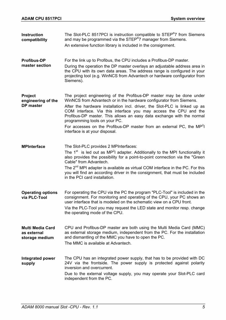
• Create a new project. • Add a profile rail from the hardware catalog. • Add the CPU "CPU 315-2DP".
You find the CPU with Profibus-DP master in the hardware catalog in: Simatic300/CPU-300/CPU315-2DP/6ES7 315-2AF01-0AB0
• Assign a Profibus address to your DP master. • Click on DP, select the operation mode "DP master" via Object
properties and confirm your entry with OK. • Click on "DP" with the right mouse button, choose "Insert master
system" and create a new Profibus subnet via NEW.
Now your Profibus-DP master is ready configured. Connect your slaves with periphery with the DP-Master. • For the project engineering of Profibus-DP slaves, you fetch the
according Profibus slave in your hardware catalog and drag'n'drop it on the subnet of your DP master. Open the new created DP Slave and you can add I/O modules of the catalogue ADAM_8000.
• Assign a valid Profibus address to the slave. • Connect the modules of your slave system in the order you plugged them
in, by assigning addresses and parameterizing the modules if needed.
Project engineering

ADAM CPU 8517PCI Deployment Profibus-DP master
18 ADAM 8000 manual Slot -CPU - Rev. 1.1

ADAM CPU 8517PCI Deployment Profibus-DP master
ADAM 8000 manual Slot -CPU - Rev. 1.1 19
After NETZ_EIN (i.e. POWER_ON) the DP master switches automatically to RUN. We abstained an operating mode lever for the DP master.
After a STOP → RUN transition of the CPU, the DP master gets its bus parameters. Now it establishes a connection to its DP slaves. During this time only the RUN-LED is blinking. When the communication has been completed and at valid bus parameters, the DP master switches to Data Exchange (DE). The LEDs RUN and DE are blinking. When receiving wrong/invalid parameters, the DP master switches to RUN and monitors a parameterization error via the IF-LED. The DP master is now linked up to the bus with the following default bus parameters: Default-Bus-Parameter: Address: 1; Transfer rate: 1,5 MBaud.
During RUN mode, the RUN- and the DE-LEDs are blinking. Now data may be transferred. In the event of an error, like e.g. a DP slave break down, this is shown at the DP master via the ERR-LED and an alarm to the CPU is initiated.
Note! If the CPU switches to STOP during operation, the DP master stays in RUN. Due to the BASP signal, all outputs of the peripheral modules connected via DP slaves, are set to zero.
DP-Master operating modes
STOP → RUN (automatically)
RUN
ADAM CPU 8517PCI Deployment of the MMC
20 ADAM 8000 manual Slot -CPU - Rev. 1.1
Deployment of the MMC
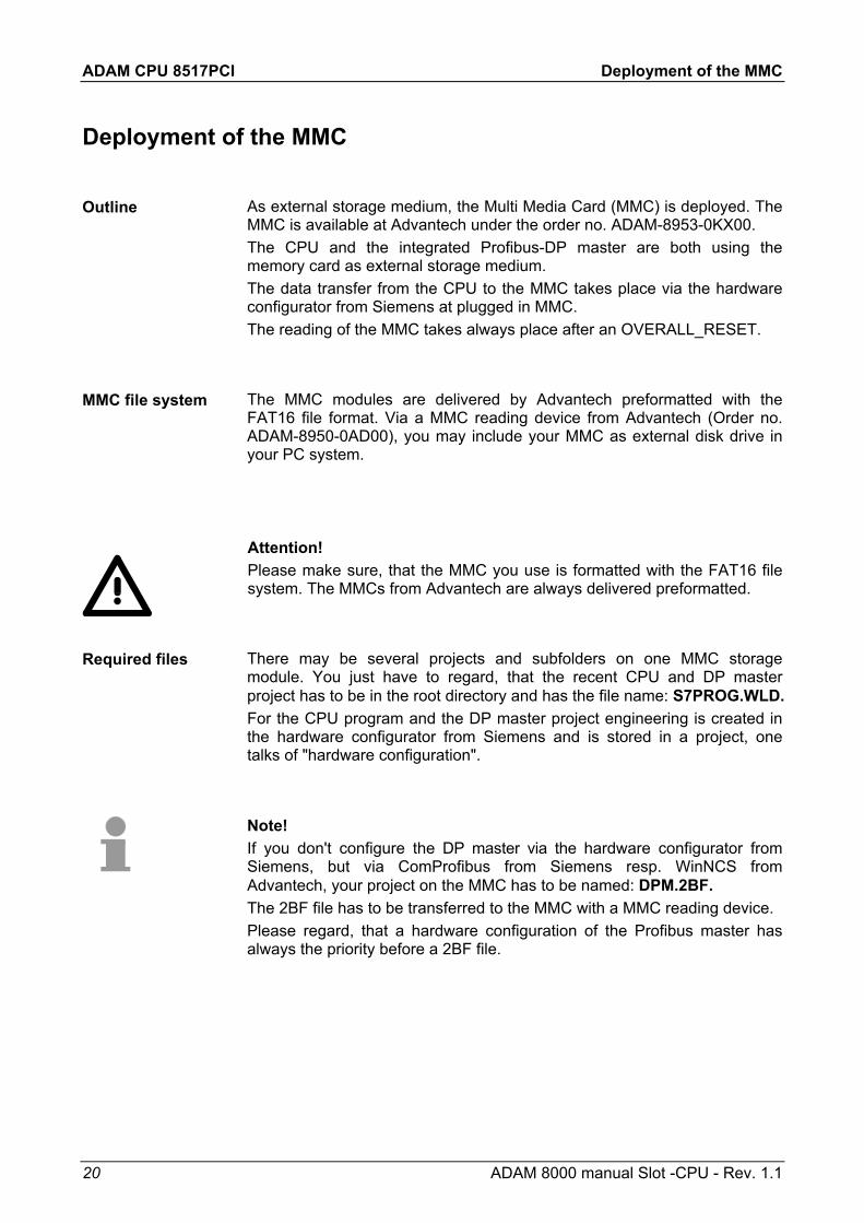
As external storage medium, the Multi Media Card (MMC) is deployed. The MMC is available at Advantech under the order no. ADAM-8953-0KX00. The CPU and the integrated Profibus-DP master are both using the memory card as external storage medium. The data transfer from the CPU to the MMC takes place via the hardware configurator from Siemens at plugged in MMC. The reading of the MMC takes always place after an OVERALL_RESET.
The MMC modules are delivered by Advantech preformatted with the FAT16 file format. Via a MMC reading device from Advantech (Order no. ADAM-8950-0AD00), you may include your MMC as external disk drive in your PC system.
Attention! Please make sure, that the MMC you use is formatted with the FAT16 file system. The MMCs from Advantech are always delivered preformatted.
There may be several projects and subfolders on one MMC storage module. You just have to regard, that the recent CPU and DP master project has to be in the root directory and has the file name: S7PROG.WLD. For the CPU program and the DP master project engineering is created in the hardware configurator from Siemens and is stored in a project, one talks of "hardware configuration".
Note! If you don't configure the DP master via the hardware configurator from Siemens, but via ComProfibus from Siemens resp. WinNCS from Advantech, your project on the MMC has to be named: DPM.2BF. The 2BF file has to be transferred to the MMC with a MMC reading device. Please regard, that a hardware configuration of the Profibus master has always the priority before a 2BF file.
Outline
MMC file system
Required files

ADAM CPU 8517PCI Deployment of the MMC
ADAM 8000 manual Slot -CPU - Rev. 1.1 21
When the MMC is plugged-in, the content of the battery buffered RAM is stored on the MMC via a write command. This is controlled by means of the Siemens STEP7 Manager via PLC > Copy RAM to ROM. During the write process the yellow "MMC"-LED of the CPU is blinking.
Note! If you initialize the write command without a plugged MMC, an error message about insufficient memory occurs.
The transfer of the application program from the MMC into the CPU takes always place after an OVERALL_RESET. The blinking of the yellow LED "MMC" of the CPU marks the active transfer. If there is no valid application program on the MMC or if the transfer should fail, the CPU switches to STOP and the "STOP"-LED blinks three times. The DP master is now at the network with the following default parameters: Default-Bus-Parameter: Address: 1; Transfer rate: 1,5 MBaud
Note! You must remember that the memory size has been tailored to the CPU! If the application program is larger than the memory available on the CPU, the content of the MMC is not transferred into the CPU. It is advisable to compress the application program before transferring it into the MMC. This doesn't happen automatically. When deploying a MMC, please regard that it is preformatted.
Transfer CPU → MMC
Transfer MMC → CPU

ADAM CPU 8517PCI Commissioning and Start-up behavior
22 ADAM 8000 manual Slot -CPU - Rev. 1.1
Commissioning and Start-up behavior
• Open your PC • If not yet done, plug a MMC in the PC card • Insert the Slot-PLC plug-in module in one not occupied PCI slot • For commissioning, leave the cabinet open. This makes the access to
the MMC and LEDs easier. • Built up your PLC system
Note! The installation of the Slot-PLC plug-in module should only be executed by properly trained personnel! Inadequate handling may cause damages at the module and the PC.
During the start-up of the PC the new hardware is recognized. To include the plug-in module as virtual COM interface, there is an according driver on the delivered CD. On the CD in the directory "Driver" you will find the driver assigned to your operating system. Select this during the hardware installation. The plug-in module is now included automatically in your system as virtual COM interface.
Please switch on the external power supply. Afterwards there are some actions in the CPU, further described under "Start-up behavior".
In delivery state, the CPU is reset. After a STOP→RUN transition of the CPU, the DP master gets its parameter data. For these are not available in the empty CPU, the DP master uses its default parameters (Adr.:1, 1,5 MBit) from the ROM, monitors this via the "IF"-LED and switches to RUN. The CPU switches into RUN without program.
If there is an application and Profibus parameters in the battery buffered RAM of the CPU, at a STOP→RUN transition of the CPU, the parameters are transmitted to the DP master. The master establishes a communication to its DP slaves. At successful communication and valid bus parameters, the DP master switches to Data Exchange (DE). The LEDs RUN and DE are blinking. The CPU switches to RUN with its application.
Check list for the commissioning
Boot PC
Switch on external power supply
Start-up at delivery
Start-up with valid data in the CPU
ADAM CPU 8517PCI Technical Data
ADAM 8000 manual Slot -CPU - Rev. 1.1 23
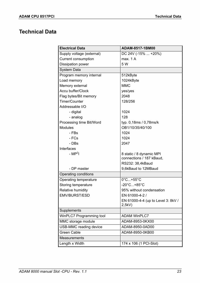
Technical Data
Electrical Data ADAM-8517-1BM00 Supply voltage (external) DC 24V (-15% ... +20%) Current consumption max. 1 A Dissipation power 5 W System Data Program memory internal 512kByte Load memory 1024kByte Memory external MMC Accu buffer/Clock yes/yes Flag bytes/Bit memory 2048 Timer/Counter 128/256 Addressable I/O - digital 1024 - analog 128 Processing time Bit/Word typ. 0,18ms / 0,78ms/k Modules - FBs - FCs - DBs
OB1/10/35/40/100 1024 1024 2047
Interfaces - MP2I 8 static / 8 dynamic MPI
connections / 187 kBaud, RS232: 38,4kBaud
- DP master 9,6kBaud to 12MBaud Operating conditions Operating temperature 0°C...+55°C Storing temperature -20°C...+85°C Relative humidity 95% without condensation EMV/BURST/ESD EN 61000-4-2 /
EN 61000-4-4 (up to Level 3: 8kV / 2,5kV)
Supplements WinPLC7 Programming tool ADAM WinPLC7 MMC storage module ADAM-8953-0KX00 USB-MMC reading device ADAM-8950-0AD00 Green Cable ADAM-8950-0KB00 Measurements Length x Width 174 x 106 (1 PCI-Slot)