manual 08/2016 simotion web-accumulator 08/2016 simotion web-accumulator . ... 5.4.4 speed setpoint...
TRANSCRIPT

https://support.industry.siemens.com/cs/ww/en/view/109744604
Manual 08/2016
SIMOTION Web-Accumulator

Warranty and liability
SIMOTION Web-Accumulator Entry-ID: 109744604, V1.0.2, 08/2016 2
S
iem
en
s A
G 2
01
6 A
ll ri
gh
ts r
ese
rve
d
Warranty and liability
Note The Application Examples are not binding and do not claim to be complete regarding the circuits shown, equipping and any eventuality. The Application Examples do not represent customer-specific solutions. They are only intended to provide support for typical applications. You are responsible for ensuring that the described products are used correctly. These Application Examples do not relieve you of the responsibility to use safe practices in application, installation, operation and maintenance. When using these Application Examples, you recognize that we cannot be made liable for any damage/claims beyond the liability clause described. We reserve the right to make changes to these Application Examples at any time without prior notice. If there are any deviations between the recommendations provided in these Application Examples and other Siemens publications – e.g. Catalogs – the contents of the other documents have priority.
We do not accept any liability for the information contained in this document. Any claims against us – based on whatever legal reason – resulting from the use of the examples, information, programs, engineering and performance data etc., described in this Application Example shall be excluded. Such an exclusion shall not apply in the case of mandatory liability, e.g. under the German Product Liability Act (“Produkthaftungsgesetz”), in case of intent, gross negligence, or injury of life, body or health, guarantee for the quality of a product, fraudulent concealment of a deficiency or breach of a condition which goes to the root of the contract (“wesentliche Vertragspflichten”). The damages for a breach of a substantial contractual obligation are, however, limited to the foreseeable damage, typical for the type of contract, except in the event of intent or gross negligence or injury to life, body or health. The above provisions do not imply a change of the burden of proof to your detriment. Any form of duplication or distribution of these Application Examples or excerpts hereof is prohibited without the expressed consent of the Siemens AG.
Security informa-tion
Siemens provides products and solutions with industrial security functions that support the secure operation of plants, systems, machines and networks. In order to protect plants, systems, machines and networks against cyber threats, it is necessary to implement – and continuously maintain – a holistic, state-of-the-art industrial security concept. Siemens’ products and solutions only form one element of such a concept. Customer is responsible to prevent unauthorized access to its plants, systems, machines and networks. Systems, machines and components should only be connected to the enterprise network or the internet if and to the extent necessary and with appropriate security measures (e.g. use of firewalls and network segmentation) in place. Additionally, Siemens’ guidance on appropriate security measures should be taken into account. For more information about industrial security, please visit http://www.siemens.com/industrialsecurity.
Siemens’ products and solutions undergo continuous development to make them more secure. Siemens strongly recommends to apply product updates as soon as available and to always use the latest product versions. Use of product versions that are no longer supported, and failure to apply latest updates may increase customer’s exposure to cyber threats. To stay informed about product updates, subscribe to the Siemens Industrial Security RSS Feed under http://www.siemens.com/industrialsecurity.
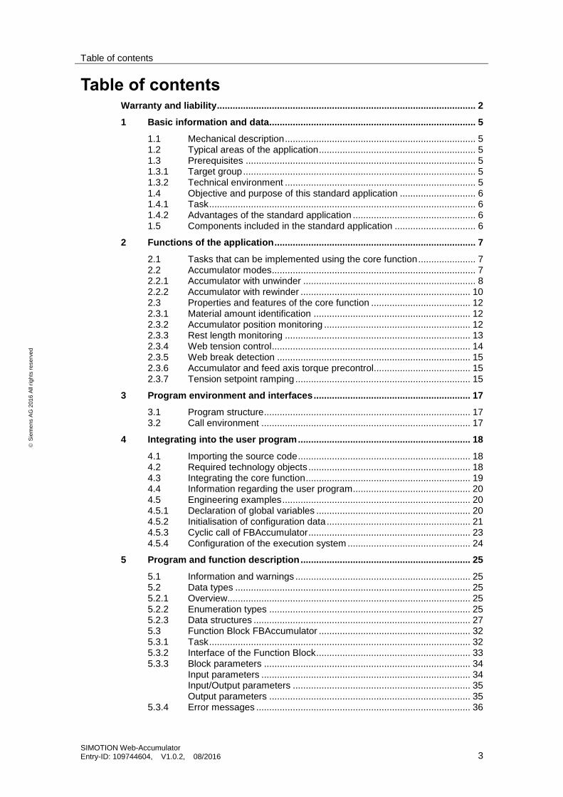
Table of contents
SIMOTION Web-Accumulator Entry-ID: 109744604, V1.0.2, 08/2016 3
S
iem
en
s A
G 2
01
6 A
ll ri
gh
ts r
ese
rve
d
Table of contents Warranty and liability ................................................................................................... 2
1 Basic information and data............................................................................... 5
1.1 Mechanical description ......................................................................... 5 1.2 Typical areas of the application ............................................................ 5 1.3 Prerequisites ........................................................................................ 5 1.3.1 Target group ......................................................................................... 5 1.3.2 Technical environment ......................................................................... 5 1.4 Objective and purpose of this standard application ............................. 6 1.4.1 Task ...................................................................................................... 6 1.4.2 Advantages of the standard application ............................................... 6 1.5 Components included in the standard application ............................... 6
2 Functions of the application ............................................................................. 7
2.1 Tasks that can be implemented using the core function ...................... 7 2.2 Accumulator modes .............................................................................. 7 2.2.1 Accumulator with unwinder .................................................................. 8 2.2.2 Accumulator with rewinder ................................................................. 10 2.3 Properties and features of the core function ...................................... 12 2.3.1 Material amount identification ............................................................ 12 2.3.2 Accumulator position monitoring ........................................................ 12 2.3.3 Rest length monitoring ....................................................................... 13 2.3.4 Web tension control ............................................................................ 14 2.3.5 Web break detection .......................................................................... 15 2.3.6 Accumulator and feed axis torque precontrol..................................... 15 2.3.7 Tension setpoint ramping ................................................................... 15
3 Program environment and interfaces ............................................................ 17
3.1 Program structure ............................................................................... 17 3.2 Call environment ................................................................................ 17
4 Integrating into the user program .................................................................. 18
4.1 Importing the source code .................................................................. 18 4.2 Required technology objects .............................................................. 18 4.3 Integrating the core function ............................................................... 19 4.4 Information regarding the user program ............................................. 20 4.5 Engineering examples ........................................................................ 20 4.5.1 Declaration of global variables ........................................................... 20 4.5.2 Initialisation of configuration data ....................................................... 21 4.5.3 Cyclic call of FBAccumulator .............................................................. 23 4.5.4 Configuration of the execution system ............................................... 24
5 Program and function description ................................................................. 25
5.1 Information and warnings ................................................................... 25 5.2 Data types .......................................................................................... 25 5.2.1 Overview............................................................................................. 25 5.2.2 Enumeration types ............................................................................. 25 5.2.3 Data structures ................................................................................... 27 5.3 Function Block FBAccumulator .......................................................... 32 5.3.1 Task .................................................................................................... 32 5.3.2 Interface of the Function Block ........................................................... 33 5.3.3 Block parameters ............................................................................... 34
Input parameters ................................................................................ 34 Input/Output parameters .................................................................... 35 Output parameters ............................................................................. 35
5.3.4 Error messages .................................................................................. 36

Table of contents
SIMOTION Web-Accumulator Entry-ID: 109744604, V1.0.2, 08/2016 4
S
iem
en
s A
G 2
01
6 A
ll ri
gh
ts r
ese
rve
d
5.4 Function description ........................................................................... 37 5.4.1 System of units ................................................................................... 38 5.4.2 Internal structure ................................................................................ 41 5.4.3 State machine .................................................................................... 42
Events for state transitions ................................................................. 42 Transition matrix ................................................................................. 44 Regular state transitions..................................................................... 46 Irregular state transitions .................................................................... 46
5.4.4 Speed setpoint calculation ................................................................. 49 5.4.5 Timing diagrams ................................................................................. 51
6 General information on the application ......................................................... 53
6.1 Scope of supply .................................................................................. 53 6.2 Abbreviations ...................................................................................... 53
7 Related literature ............................................................................................. 55
8 Contact.............................................................................................................. 55
9 History............................................................................................................... 55
1 Basic information and data
1.1 Mechanical description
SIMOTION Web-Accumulator Entry-ID: 109744604, V1.0.2, 08/2016 5
S
iem
en
s A
G 2
01
6 A
ll ri
gh
ts r
ese
rve
d
1 Basic information and data
1.1 Mechanical description
A web accumulator works per definition as a material buffer. This functionality is needed for realizing reelchanges of un- or rewinders without interrupting the process. By this the productivity of the machine is increased.
Typically, a web accumulator is found behind an unwinder or before a rewinder. With the web accumulator slowing down the winders is possible and thereby enabling a reelchange without stopping the machine.
Examples for web accumulators:
figure 1-1: variations of web accumulators
vertically horizontally
Typically an accumulator consists of the accumulator axis – which actually buffers the material – accompanied with a feeder axis and a dancer roll or load measuring cell to maintain proper web tension.
A web accumulator is made for decoupling the winder / unwinder from the converting process. E.g. to enable reelchanges without varying the machine speed or stopping the machine. To this the accumulator will be charged (rewinder) or discharged (unwinder).
1.2 Typical areas of the application
Machines, where an accumulator is present to enable material intake or uptake during winder coil change without stopping the converting process.
1.3 Prerequisites
It is necessary to have a good understanding of SIMOTION, SCOUT Engineering System and at least a basic understanding of the technological function.
The application is available as a SIMOTION library programmed in the Structured Text programming language. The application strictly depends on the presence of the Converting Library LConLib, which is also available in SIOS (https://support.industry.siemens.com/cs/ww/en/view/48805235)
1.3.1 Target group
Projecting engineers, who have experience with SIMOTION and aim to implement accumulator functionality in a converting machine.
1.3.2 Technical environment
This application is intended to be used in a SIMOTION Motion Control environment.
1 Basic information and data
1.4 Objective and purpose of this standard application
SIMOTION Web-Accumulator Entry-ID: 109744604, V1.0.2, 08/2016 6
S
iem
en
s A
G 2
01
6 A
ll ri
gh
ts r
ese
rve
d
1.4 Objective and purpose of this standard application
This SIMOTION standard application was developed with the objective of creating a flexible solution for converting machines where an accumulator is used. It can be fitted to ones needs by parametrization due to the fact, that it is open source.
1.4.1 Task
The application can be easily adapted to specific machines by parametrisation. As a result of the openness of the software structure the application can also be modified if that is necessary.
1.4.2 Advantages of the standard application
When the standard application SIMOTION Winder is used, it offers users the following advantages:
Reduction of engineering time
When the standard application SIMOTION Winder is used, it is simple to quickly implement an comprehensive winder functionality when programming with SIMOTION.
The core function can be imported into the user program. Additional engineering steps that are required are explained in this description of the standard application.
Possibility of making changes
The standard application SIMOTION Winder includes all of the source codes in a commented form. This means that the core functions can be quickly and simply expanded using your own functions.
An explanation regarding background information that is required to expand the core functions is also included in this description.
Engineering is reduced to parametrisation. Advantages are the reduction of engineering time, easy commissioning due to ready to apply concept and detailed documentation.
1.5 Components included in the standard application
This application consists of one core unit (FBAccumulator) which coordinates the various functions associated with the accumulator.
2 Functions of the application
2.1 Tasks that can be implemented using the core function
SIMOTION Web-Accumulator Entry-ID: 109744604, V1.0.2, 08/2016 7
S
iem
en
s A
G 2
01
6 A
ll ri
gh
ts r
ese
rve
d
2 Functions of the application
2.1 Tasks that can be implemented using the core function
The application SIMOTION Web Accumulator calculates the speed setpoint for the winch and the infeed. The SIMOTION Winder standard application is working independent from the SIMOTION Web Accumulator package and is not included in it.
The core functionality is realized with a function block for controlling and calculating the necessary signals and setpoints. The function block has to be parametrized correspondingly to its use.
The core functionality can/must be adapted outside of the function block.
In particular this applies to:
activating axes
free jogging operations
free positioning operations
NOTE For implementing basis axis functionality reference is made to the applications SIMOTION Axis Function Block or SIMOTION Line Axis. The mentioned functionality can be combined and expanded.
2.2 Accumulator modes
An accumulator can be used both in conjunction with an unwinder or a rewinder.
If it is used together with an unwinder it acts as material source during coil change, meaning that the buffered material is output by the accumulator to the converting process.
If the accumulator is located between the rewinder and the converting process it is used to save the converted material while the rewinder is stopped for coil change.
The mode of the accumulator can be selected with a respective parameter.
In both modes the accumulator axis is practically a slave of the feed axis, therefore the different phases, states of the accumulating is defined by the state of the feed axis. The accumulator axis has two states: standstill or moving – aside emergency stop.
2 Functions of the application
2.2 Accumulator modes
SIMOTION Web-Accumulator Entry-ID: 109744604, V1.0.2, 08/2016 8
S
iem
en
s A
G 2
01
6 A
ll ri
gh
ts r
ese
rve
d
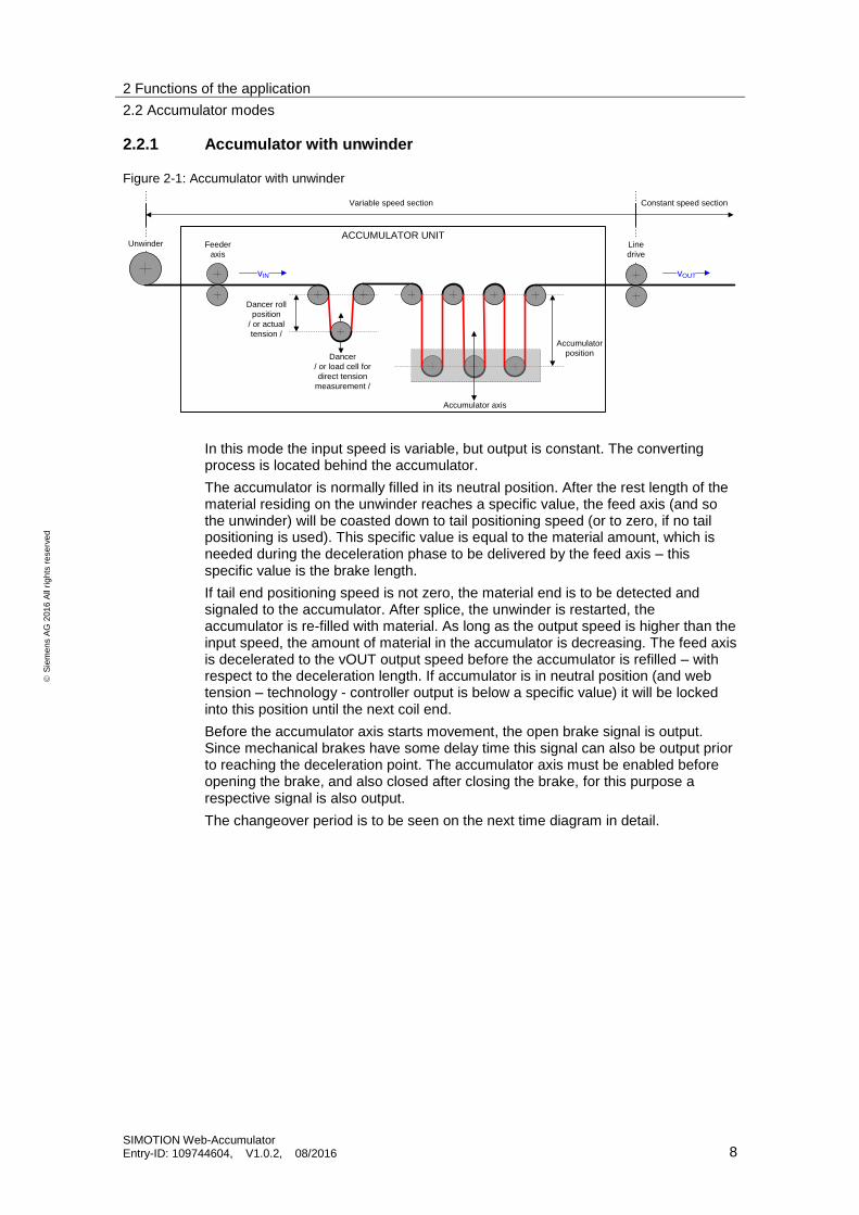
2.2.1 Accumulator with unwinder
Figure 2-1: Accumulator with unwinder
ACCUMULATOR UNIT
Dancer roll
position
/ or actual
tension /Accumulator
position
Feeder
axis
Line
drive
Accumulator axis
Dancer
/ or load cell for
direct tension
measurement /
Unwinder
Variable speed section Constant speed section
vIN vOUT
In this mode the input speed is variable, but output is constant. The converting process is located behind the accumulator.
The accumulator is normally filled in its neutral position. After the rest length of the material residing on the unwinder reaches a specific value, the feed axis (and so the unwinder) will be coasted down to tail positioning speed (or to zero, if no tail positioning is used). This specific value is equal to the material amount, which is needed during the deceleration phase to be delivered by the feed axis – this specific value is the brake length.
If tail end positioning speed is not zero, the material end is to be detected and signaled to the accumulator. After splice, the unwinder is restarted, the accumulator is re-filled with material. As long as the output speed is higher than the input speed, the amount of material in the accumulator is decreasing. The feed axis is decelerated to the vOUT output speed before the accumulator is refilled – with respect to the deceleration length. If accumulator is in neutral position (and web tension – technology - controller output is below a specific value) it will be locked into this position until the next coil end.
Before the accumulator axis starts movement, the open brake signal is output. Since mechanical brakes have some delay time this signal can also be output prior to reaching the deceleration point. The accumulator axis must be enabled before opening the brake, and also closed after closing the brake, for this purpose a respective signal is also output.
The changeover period is to be seen on the next time diagram in detail.
2 Functions of the application
2.2 Accumulator modes
SIMOTION Web-Accumulator Entry-ID: 109744604, V1.0.2, 08/2016 9
Siemens AG 2016 All rights reserved
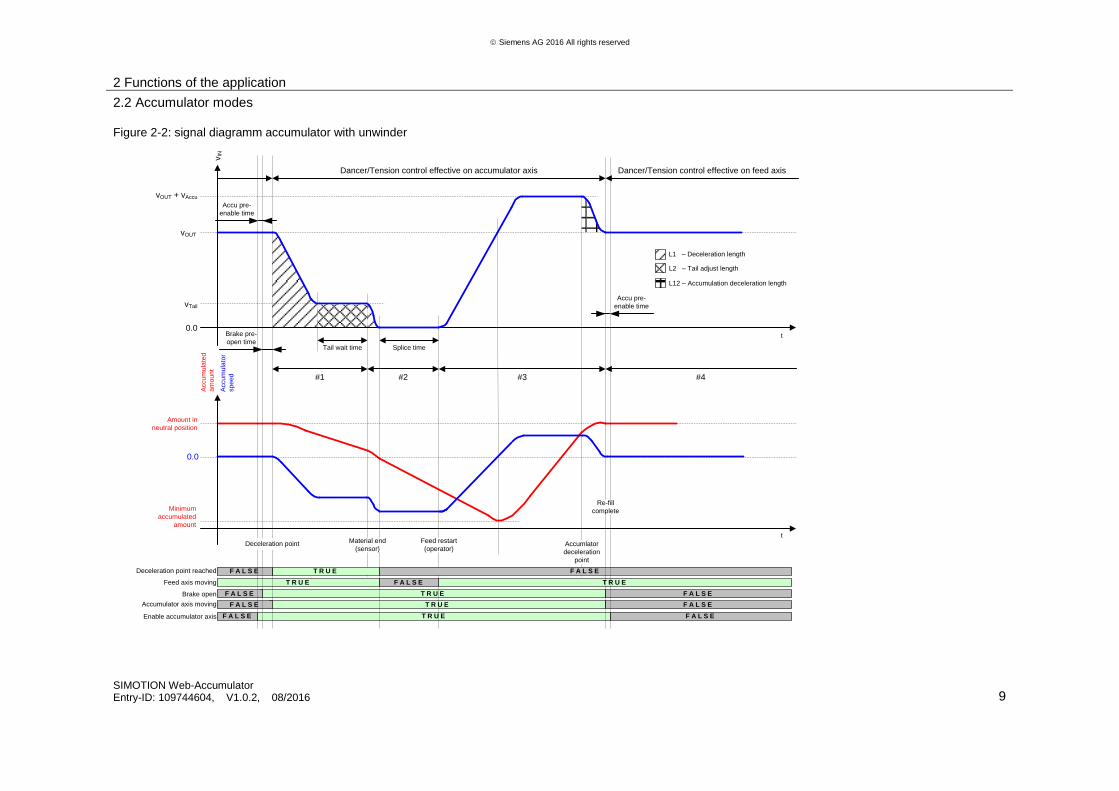
Figure 2-2: signal diagramm accumulator with unwinder
T R U E
T R U E
T R U E
T R U E
T R U E
Material end
(sensor)
Feed restart
(operator)Accumlator
deceleration
point
vOUT
vTail
0.0
vOUT + vAccu
vIN
t
t
Minimum
accumulated
amount
Amount in
neutral position
Accu
mu
late
d
am
ou
nt
Tail wait time Splice time
Dancer/Tension control effective on accumulator axis Dancer/Tension control effective on feed axis
L1 – Deceleration length
L2 – Tail adjust length
L12 – Accumulation deceleration length
0.0
Accu
mu
lato
r
sp
ee
d #1 #2 #3 #4
F A L S E
T R U E F A L S E
F A L S E
F A L S E
F A L S E
F A L S E
F A L S E
Brake open
Accumulator axis moving
Feed axis moving
Deceleration point reached
Brake pre-
open time
F A L S EF A L S EEnable accumulator axis
Accu pre-
enable time
Accu pre-
enable time
Re-fill
complete
Deceleration point
2 Functions of the application
2.2 Accumulator modes
SIMOTION Web-Accumulator Entry-ID: 109744604, V1.0.2, 08/2016 10
S
iem
en
s A
G 2
01
6 A
ll ri
gh
ts r
ese
rve
d
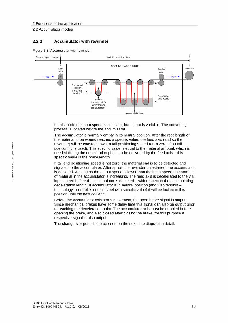
2.2.2 Accumulator with rewinder
Figure 2-3: Accumulator with rewinder
ACCUMULATOR UNIT
Dancer roll
position
/ or actual
tension /Accumulator
axis position
Feeder
axis
Line
drive
Accumulator axis
Dancer
/ or load cell for
direct tension
measurement /
Rewinder
Variable speed sectionConstant speed section
vIN vOUT
In this mode the input speed is constant, but output is variable. The converting process is located before the accumulator.
The accumulator is normally empty in its neutral position. After the rest length of the material to be wound reaches a specific value, the feed axis (and so the rewinder) will be coasted down to tail positioning speed (or to zero, if no tail positioning is used). This specific value is equal to the material amount, which is needed during the deceleration phase to be delivered by the feed axis – this specific value is the brake length.
If tail end positioning speed is not zero, the material end is to be detected and signaled to the accumulator. After splice, the rewinder is restarted, the accumulator is depleted. As long as the output speed is lower than the input speed, the amount of material in the accumulator is increasing. The feed axis is decelerated to the vIN input speed before the accumulator is depleted – with respect to the accumulating deceleration length. If accumulator is in neutral position (and web tension – technology - controller output is below a specific value) it will be locked in this position until the next coil end.
Before the accumulator axis starts movement, the open brake signal is output. Since mechanical brakes have some delay time this signal can also be output prior to reaching the deceleration point. The accumulator axis must be enabled before opening the brake, and also closed after closing the brake, for this purpose a respective signal is also output.
The changeover period is to be seen on the next time diagram in detail.

2 Functions of the application
2.2 Accumulator modes
SIMOTION Web-Accumulator Entry-ID: 109744604, V1.0.2, 08/2016 11
Siemens AG 2016 All rights reserved
Figure 2-4: signal diagram accumulator with rewinder
T R U E F A L S EF A L S EEnable accumulator axis
T R U E
T R U E
T R U E
T R U E
T R U E
Material end
(sensor)Feed restart
(operator)
Accumulator
deceleration
point
VIN
vTail
0.0
vIN + vAccu
vO
UT
t
t
Tail wait time Splice time
Dancer/Tension control effective on accumulator axis Dancer/Tension control effective on feed axis
L1 – Deceleration length
L2 – Tail adjust length
L12 – Accumulation deceleration length
Maximum
accumulated
amount
Amount in
neutral position
Accu
mu
late
d
am
ou
nt
0.0
Accu
mu
lato
r
sp
ee
d #1 #2 #3 #4
Brake pre-
open time
F A L S E
F A L S E
F A L S E
F A L S E
F A L S E
F A L S E
F A L S E
Brake open
Accumulator axis moving
Feed axis moving
Deceleration point reached
Re-fill
complete
Deceleration point
Accu pre-
enable time
Accu pre-
enable time
2 Functions of the application
2.3 Properties and features of the core function
SIMOTION Web-Accumulator Entry-ID: 109744604, V1.0.2, 08/2016 12
S
iem
en
s A
G 2
01
6 A
ll ri
gh
ts r
ese
rve
d
2.3 Properties and features of the core function
The most important function of the application is to calculate velocity setpoint for the feed and accumulator axes. Several other functions are also implemented in this application, some of these are necessary for accumulator control others are implemented to offer enriched functionality. Setpoint calculation for feed and material axis is described in detail in chapter 5.4.4. Basically the feed axis setpoint follows the line setpoint and accumulator axis is in standstill – unless the rest length for winding reaches a specific value. If this value is reached, the feed axis is decelerated, the accumulator axis temporary acts as an unwinder (intake) or rewinder (uptake). After the winding coil is changed, feed axis is restarted, accumulator reaches neutral position and feed axis will follow the line speed again.
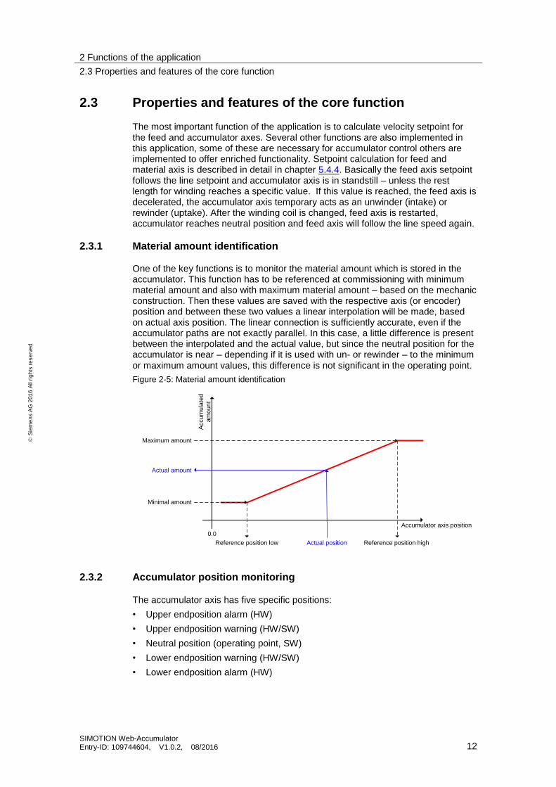
2.3.1 Material amount identification
One of the key functions is to monitor the material amount which is stored in the accumulator. This function has to be referenced at commissioning with minimum material amount and also with maximum material amount – based on the mechanic construction. Then these values are saved with the respective axis (or encoder) position and between these two values a linear interpolation will be made, based on actual axis position. The linear connection is sufficiently accurate, even if the accumulator paths are not exactly parallel. In this case, a little difference is present between the interpolated and the actual value, but since the neutral position for the accumulator is near – depending if it is used with un- or rewinder – to the minimum or maximum amount values, this difference is not significant in the operating point.
Figure 2-5: Material amount identification
Accumulator axis position
Accu
mu
late
d
am
ou
nt
0.0
Minimal amount
Maximum amount
Reference position highActual position
Actual amount
Reference position low
2.3.2 Accumulator position monitoring
The accumulator axis has five specific positions:
• Upper endposition alarm (HW)
• Upper endposition warning (HW/SW)
• Neutral position (operating point, SW)
• Lower endposition warning (HW/SW)
• Lower endposition alarm (HW)

2 Functions of the application
2.3 Properties and features of the core function
SIMOTION Web-Accumulator Entry-ID: 109744604, V1.0.2, 08/2016 13
S
iem
en
s A
G 2
01
6 A
ll ri
gh
ts r
ese
rve
d
If the accumulator is filled or empty – depending on the location of the accumulator – it is in the neutral position. During depletion or fill the axis is moving between the endpositions.
If one of the endpositions for warning is reached, a respective signal is output. The warning signal can be an external sensor with a respective signal input or be a direct position limit which is monitored by the function block and in this case possibly delayed with a time-on delay function. Also, if the signal is produced by the function block based on software limits, the reset of the signal is delayed with a time-off delay, and a hysteresis can also be set. See the following figure for details.
Figure 2-6
warning1
0
TON-delay TOF-delayTON-delay
time
axis
po
sitio
n
warning level
warning level
- hysteresis
Case 1 Case 2 Case 3 Case 4
Case 1: Position is above the warning level for less than the TON-delay.
Case 2: Position is above the warning level for a longer time than the TON-delay
Case 3: Position falls below the warning level, but not under the hysteresis.
Case 4: Position leaves the hysteresis and the signal is reset after the TOF-delay.
The reaction to this warning is to be defined by the user – outside of the function block.
If one endposition for alarm is reached, the accumulator and feed axes are stopped immediately. There is no delay time to alarm limits, and alarm limits can only be signal inputs.
2.3.3 Rest length monitoring
The residual material amount to unwind from or rewind on the coil is calculated internally (refer to function FCRLC, which is described in the User Manual Converting Library. The calculated length is evaluated by the accumulator unit and automatic deceleration for un- or rewinder side feed axis is initiated.
The precision of the calculated rest length is a key element for the determination of exact automatic stop for coil change.

2 Functions of the application
2.3 Properties and features of the core function
SIMOTION Web-Accumulator Entry-ID: 109744604, V1.0.2, 08/2016 14
S
iem
en
s A
G 2
01
6 A
ll ri
gh
ts r
ese
rve
d
2.3.4 Web tension control
The web tension within the accumulator unit is maintained with the technology controller, which can also work with dancer position or measured tension (with load cell) values. The technology controller is basically a PID controller with enriched functionality. The controller unit itself is described in the User Manual Converting Library. The web tension in this section is independent from the winder section tension. The output of the technology controller is used as velocity correction on the feed axis if the accumulator axis is in standstill or on the accumulator axis, if the accumulator axis is moving (during fill or depletion).
Aside the web tension control it is also possible to detect potential web break. Web break detection relies on the feedback of the technology variable (actual dancer position or measured tension) and predefined limits for this feedback value. Web break detection is optional, also a minimum line speed and a timeon delay can be set to avoid false detection of web break. Only an output signal is set in case of web break detection, no automatic reaction is carried out.
The technology controller as mentioned above is effective on the feed axis and also on the accumulator axis, depending on the actual state. The switchover takes place at the start and stop of the accumulator axis, and is controlled so, that there is no sudden jump in speed setpoints. This procedure can be observed on the next figure.
Figure 2-7: Technology controller switchover
1
0
1
0
1
0
Actual amount =
neutral amount
Feed running
Accu running
Controller output
AA
Feed state
Controller output
FA
0
0
1 2 5 6 8 1
(a)
3 4 7
(b) (c) (d) (e) (f) (g)
(h)
(i)
Changeover limit
a) The deceleration point is reached, feed axis is decelerated to tail end positioning speed. The output limit of technology controller which is effective on the feed axis is ramped to zero, the output limit of the technology controller which is effective on the accumulator axis is ramped to maximum value.
b) Tail end positioning speed is reached.
c) Material end is detected, feed axis is decelerated to standstill.
d) Feed axis is in standstill.
e) Feed axis is restarted and accelerated to accumulating speed.
f) Accumulating speed is reached.
2 Functions of the application
2.3 Properties and features of the core function
SIMOTION Web-Accumulator Entry-ID: 109744604, V1.0.2, 08/2016 15
S
iem
en
s A
G 2
01
6 A
ll ri
gh
ts r
ese
rve
d
g) Line speed deceleration point is reached, feed axis is decelerated to line speed.
h) Accumulated amount equals the neutral amount and feed axis reached line speed, but the output of the technology controller which is effective on the accumulator axis is above the specified switchover value.
i) The output of the technology controller which is effective on the accumulator axis falls below the switchover limit, web tension control is re-activated on the feed axis and the accumulator axis is stopped.
2.3.5 Web break detection
Web break detection compares the actual value of the technology controller (actual dancer position or actual tension) with parameterizable border values. If those values get exceeded, a reaction time gets activated and after expiration a responsive feedback is generated. Web break detection is optional and is activated by an input signal and a parametrizable velocity threshold.
The reaction to web break hast to be defined in the user program.
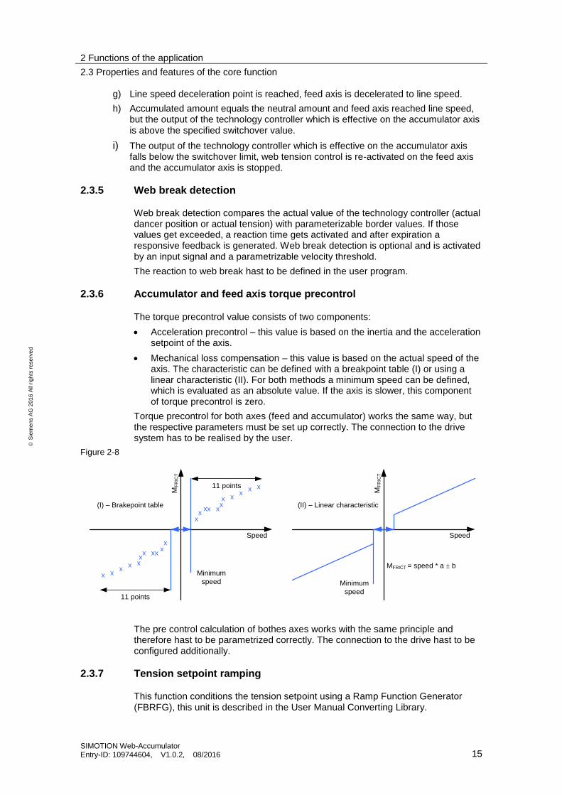
2.3.6 Accumulator and feed axis torque precontrol
The torque precontrol value consists of two components:
Acceleration precontrol – this value is based on the inertia and the acceleration setpoint of the axis.
Mechanical loss compensation – this value is based on the actual speed of the axis. The characteristic can be defined with a breakpoint table (I) or using a linear characteristic (II). For both methods a minimum speed can be defined, which is evaluated as an absolute value. If the axis is slower, this component of torque precontrol is zero.
Torque precontrol for both axes (feed and accumulator) works the same way, but the respective parameters must be set up correctly. The connection to the drive system has to be realised by the user.
Figure 2-8
Speed
MF
RIC
T
x
xx
x
x xx
xx
x
x
x
xx
x
xxx
xx
x
x
(I) – Brakepoint table
11 points
11 points
Speed
MF
RIC
T
(II) – Linear characteristic
MFRICT = speed * a ± bMinimum
speed Minimum
speed
The pre control calculation of bothes axes works with the same principle and therefore hast to be parametrized correctly. The connection to the drive hast to be configured additionally.
2.3.7 Tension setpoint ramping
This function conditions the tension setpoint using a Ramp Function Generator (FBRFG), this unit is described in the User Manual Converting Library.

2 Functions of the application
2.3 Properties and features of the core function
SIMOTION Web-Accumulator Entry-ID: 109744604, V1.0.2, 08/2016 16
S
iem
en
s A
G 2
01
6 A
ll ri
gh
ts r
ese
rve
d
There are two methods to maintain the tension of the material web:
• Dancer control, here the ramped tension setpoint can be used as a setpoint for air pressure or as setpoint for any other similar quantity which is associated with the force, that the dancer arm exerts on the material.
• Tension control with load cell, here the ramped tension setpoint output is to be connected to the respective input of the technology controller. This connection is not made automatically within the accumulator function block.
3 Program environment and interfaces
3.1 Program structure
SIMOTION Web-Accumulator Entry-ID: 109744604, V1.0.2, 08/2016 17
S
iem
en
s A
G 2
01
6 A
ll ri
gh
ts r
ese
rve
d
3 Program environment and interfaces
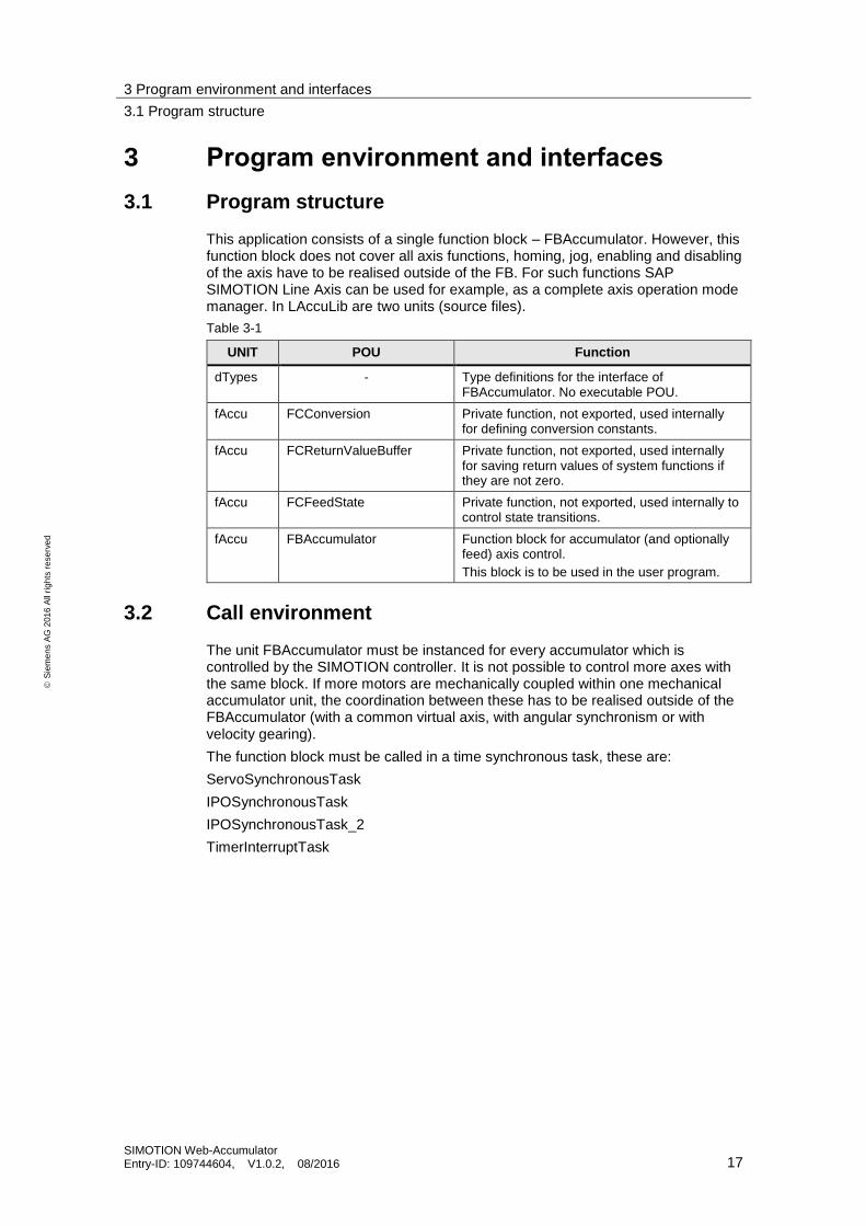
3.1 Program structure
This application consists of a single function block – FBAccumulator. However, this function block does not cover all axis functions, homing, jog, enabling and disabling of the axis have to be realised outside of the FB. For such functions SAP SIMOTION Line Axis can be used for example, as a complete axis operation mode manager. In LAccuLib are two units (source files).
Table 3-1
UNIT POU Function
dTypes - Type definitions for the interface of FBAccumulator. No executable POU.
fAccu FCConversion Private function, not exported, used internally for defining conversion constants.
fAccu FCReturnValueBuffer Private function, not exported, used internally for saving return values of system functions if they are not zero.
fAccu FCFeedState Private function, not exported, used internally to control state transitions.
fAccu FBAccumulator Function block for accumulator (and optionally feed) axis control.
This block is to be used in the user program.
3.2 Call environment
The unit FBAccumulator must be instanced for every accumulator which is controlled by the SIMOTION controller. It is not possible to control more axes with the same block. If more motors are mechanically coupled within one mechanical accumulator unit, the coordination between these has to be realised outside of the FBAccumulator (with a common virtual axis, with angular synchronism or with velocity gearing).
The function block must be called in a time synchronous task, these are:
ServoSynchronousTask
IPOSynchronousTask
IPOSynchronousTask_2
TimerInterruptTask
4 Integrating into the user program
4.1 Importing the source code
SIMOTION Web-Accumulator Entry-ID: 109744604, V1.0.2, 08/2016 18
S
iem
en
s A
G 2
01
6 A
ll ri
gh
ts r
ese
rve
d
4 Integrating into the user program The following steps are necessary to successfully integrate the SIMOTION Web Accumulator standard application into a new project. Please keep in mind, that the integration of the application just by itself does not realise all typical machine functions, please refer to chapter 3.1 Program structure.
4.1 Importing the source code
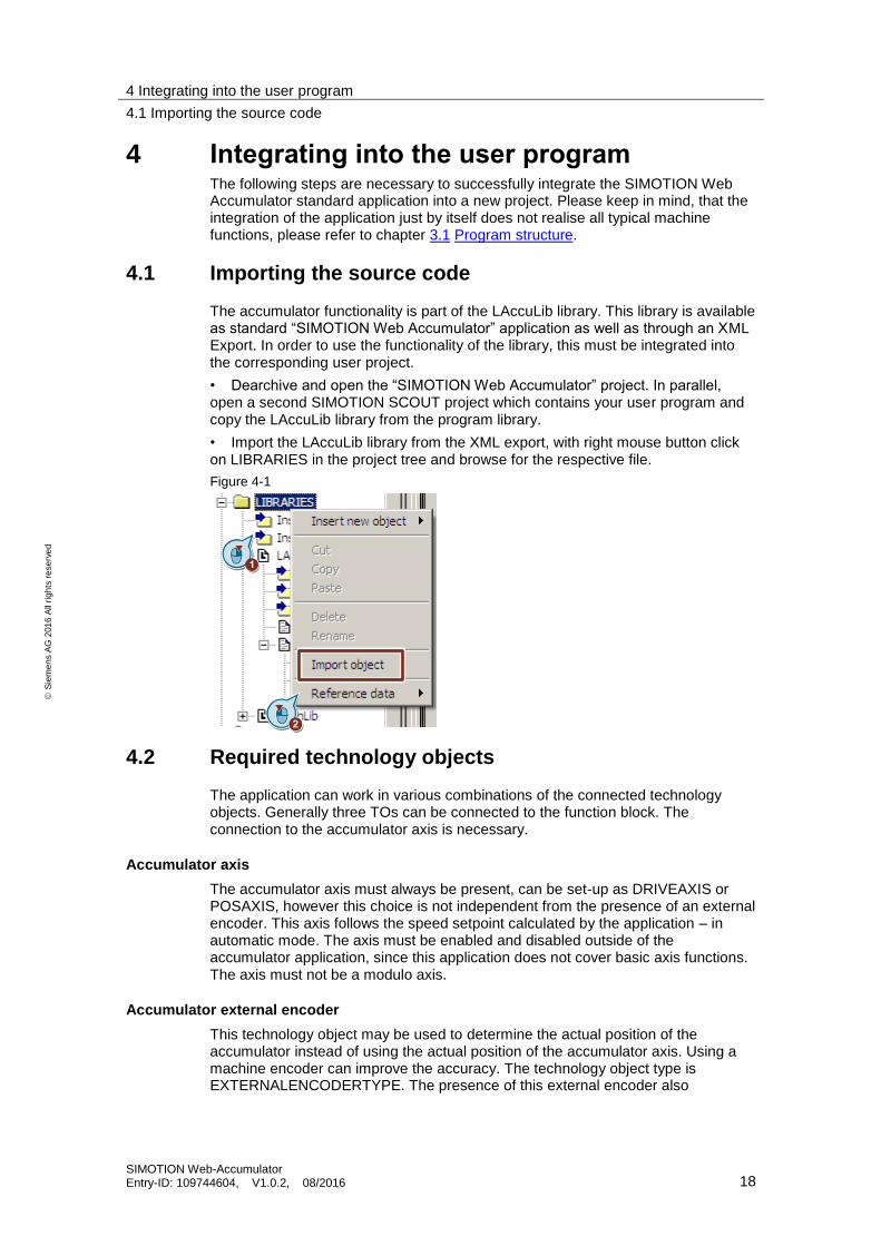
The accumulator functionality is part of the LAccuLib library. This library is available as standard “SIMOTION Web Accumulator” application as well as through an XML Export. In order to use the functionality of the library, this must be integrated into the corresponding user project.
• Dearchive and open the “SIMOTION Web Accumulator” project. In parallel, open a second SIMOTION SCOUT project which contains your user program and copy the LAccuLib library from the program library.
• Import the LAccuLib library from the XML export, with right mouse button click on LIBRARIES in the project tree and browse for the respective file.
Figure 4-1
4.2 Required technology objects
The application can work in various combinations of the connected technology objects. Generally three TOs can be connected to the function block. The connection to the accumulator axis is necessary.
Accumulator axis
The accumulator axis must always be present, can be set-up as DRIVEAXIS or POSAXIS, however this choice is not independent from the presence of an external encoder. This axis follows the speed setpoint calculated by the application – in automatic mode. The axis must be enabled and disabled outside of the accumulator application, since this application does not cover basic axis functions. The axis must not be a modulo axis.
Accumulator external encoder
This technology object may be used to determine the actual position of the accumulator instead of using the actual position of the accumulator axis. Using a machine encoder can improve the accuracy. The technology object type is EXTERNALENCODERTYPE. The presence of this external encoder also

4 Integrating into the user program
4.3 Integrating the core function
SIMOTION Web-Accumulator Entry-ID: 109744604, V1.0.2, 08/2016 19
S
iem
en
s A
G 2
01
6 A
ll ri
gh
ts r
ese
rve
d
determines the permissible type of the accumulator axis, defined by the following table.
Table 4-1
Accumulator external encoder
NOT_PRESENT PRESENT
Ac
cu
mu
lato
r a
xis
ty
pe
DR
IVE
AX
IS
ERROR OK
PO
SA
XIS
OK OK
The presence of an external encoder and the type of the accumulator axis is not irrelevant. If an external encoder is connected, that is used as position reference for the identification of the accumulated amount, a DRIVEAXIS can be used. If no external encoder is connected, the accumulator axis must be an axis with position interface, and this position will be used as position reference.
Modulo must not be enabled on the external encoder.
Feed axis
The presence of the feed axis is optional. If it is not present, torque precontrol for the feed axis is disabled, but in automatic mode the speed setpoint will still be calculated, but not activated on any axis. If the axis is present, it can be set-up as DRIVEAXIS or as POSAXIS. In this case, the speed setpoint is activated on the feed axis – in automatic mode.
4.3 Integrating the core function
For accumulator functionality the FBAccumulator function block must be integrated into the user program. First declare the instance of FBAccumulator and also the configuration structure (gsConfigData). This structure can be setup within the startup task.
Create a POU where the FB instances are called and parametrize the function block, then assign this program to a time synchronous task in the execution system.

4 Integrating into the user program
4.4 Information regarding the user program
SIMOTION Web-Accumulator Entry-ID: 109744604, V1.0.2, 08/2016 20
S
iem
en
s A
G 2
01
6 A
ll ri
gh
ts r
ese
rve
d
Figure 4-2
4.4 Information regarding the user program
The user is responsible for integrating the function blocks into his automation solution or his user program. This includes, among other things, activating, referencing, positioning and jogging the axes, the operating states of the machine, the data management and alarm handling. Also included are the emergency shutdown and where relevant, the implementation of monitoring functions.
4.5 Engineering examples
In this chapter are program examples shown in detail for the declaration and initialisation of configuration datasets and also for the call of the function block. These program examples are not part of the LAccuLib library, they are available separately as exported ST source files.
4.5.1 Declaration of global variables
The FB instance and the configuration structure are declared in the unit dGlobal – as global variables. In the interface section of this unit the LAccuLib library must be imported. In this unit no program is declared, implementation part is empty.
4 Integrating into the user program
4.5 Engineering examples
SIMOTION Web-Accumulator Entry-ID: 109744604, V1.0.2, 08/2016 21
S
iem
en
s A
G 2
01
6 A
ll ri
gh
ts r
ese
rve
d
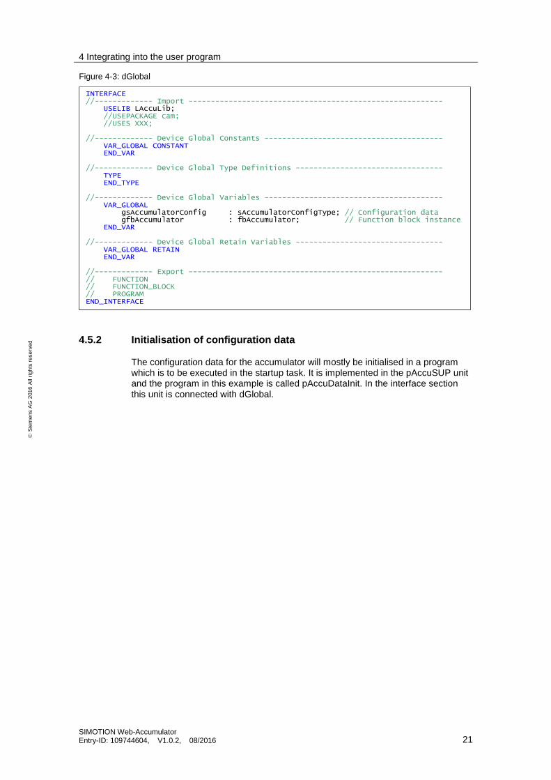
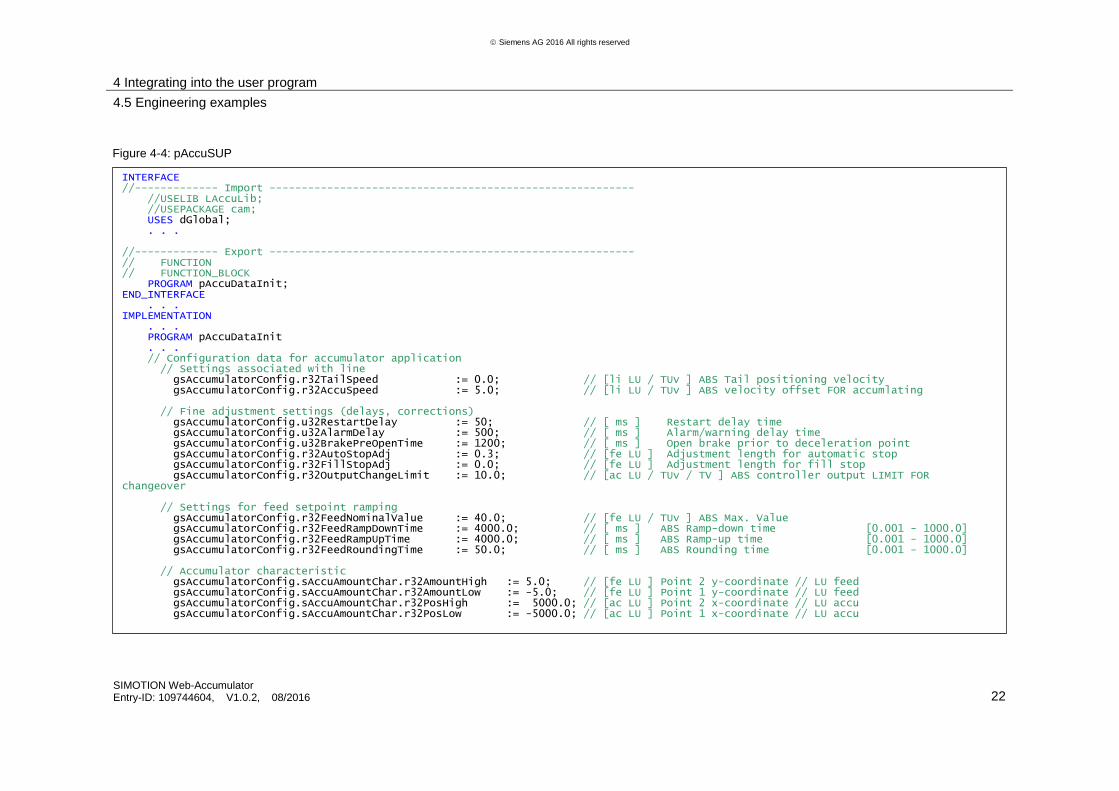
4.5.2 Initialisation of configuration data
The configuration data for the accumulator will mostly be initialised in a program which is to be executed in the startup task. It is implemented in the pAccuSUP unit and the program in this example is called pAccuDataInit. In the interface section this unit is connected with dGlobal.
INTERFACE //------------- Import --------------------------------------------------------- USELIB LAccuLib; //USEPACKAGE cam; //USES XXX; //------------- Device Global Constants ---------------------------------------- VAR_GLOBAL CONSTANT END_VAR //------------- Device Global Type Definitions --------------------------------- TYPE END_TYPE //------------- Device Global Variables ---------------------------------------- VAR_GLOBAL gsAccumulatorConfig : sAccumulatorConfigType; // Configuration data gfbAccumulator : fbAccumulator; // Function block instance END_VAR //------------- Device Global Retain Variables --------------------------------- VAR_GLOBAL RETAIN END_VAR //------------- Export --------------------------------------------------------- // FUNCTION // FUNCTION_BLOCK // PROGRAM END_INTERFACE
Figure 4-3: dGlobal
4 Integrating into the user program
4.5 Engineering examples
SIMOTION Web-Accumulator Entry-ID: 109744604, V1.0.2, 08/2016 22
Siemens AG 2016 All rights reserved
INTERFACE //------------- Import --------------------------------------------------------- //USELIB LAccuLib; //USEPACKAGE cam; USES dGlobal; . . . //------------- Export --------------------------------------------------------- // FUNCTION // FUNCTION_BLOCK PROGRAM pAccuDataInit; END_INTERFACE . . . IMPLEMENTATION . . . PROGRAM pAccuDataInit . . . // Configuration data for accumulator application // Settings associated with line gsAccumulatorConfig.r32TailSpeed := 0.0; // [li LU / TUv ] ABS Tail positioning velocity gsAccumulatorConfig.r32AccuSpeed := 5.0; // [li LU / TUv ] ABS velocity offset FOR accumlating // Fine adjustment settings (delays, corrections) gsAccumulatorConfig.u32RestartDelay := 50; // [ ms ] Restart delay time gsAccumulatorConfig.u32AlarmDelay := 500; // [ ms ] Alarm/warning delay time gsAccumulatorConfig.u32BrakePreOpenTime := 1200; // [ ms ] Open brake prior to deceleration point gsAccumulatorConfig.r32AutoStopAdj := 0.3; // [fe LU ] Adjustment length for automatic stop gsAccumulatorConfig.r32FillStopAdj := 0.0; // [fe LU ] Adjustment length for fill stop gsAccumulatorConfig.r32OutputChangeLimit := 10.0; // [ac LU / TUv / TV ] ABS controller output LIMIT FOR changeover // Settings for feed setpoint ramping gsAccumulatorConfig.r32FeedNominalValue := 40.0; // [fe LU / TUv ] ABS Max. Value gsAccumulatorConfig.r32FeedRampDownTime := 4000.0; // [ ms ] ABS Ramp-down time [0.001 - 1000.0] gsAccumulatorConfig.r32FeedRampUpTime := 4000.0; // [ ms ] ABS Ramp-up time [0.001 - 1000.0] gsAccumulatorConfig.r32FeedRoundingTime := 50.0; // [ ms ] ABS Rounding time [0.001 - 1000.0] // Accumulator characteristic gsAccumulatorConfig.sAccuAmountChar.r32AmountHigh := 5.0; // [fe LU ] Point 2 y-coordinate // LU feed gsAccumulatorConfig.sAccuAmountChar.r32AmountLow := -5.0; // [fe LU ] Point 1 y-coordinate // LU feed gsAccumulatorConfig.sAccuAmountChar.r32PosHigh := 5000.0; // [ac LU ] Point 2 x-coordinate // LU accu gsAccumulatorConfig.sAccuAmountChar.r32PosLow := -5000.0; // [ac LU ] Point 1 x-coordinate // LU accu
Figure 4-4: pAccuSUP
4 Integrating into the user program
4.5 Engineering examples
SIMOTION Web-Accumulator Entry-ID: 109744604, V1.0.2, 08/2016 23
Siemens AG 2016 All rights reserved
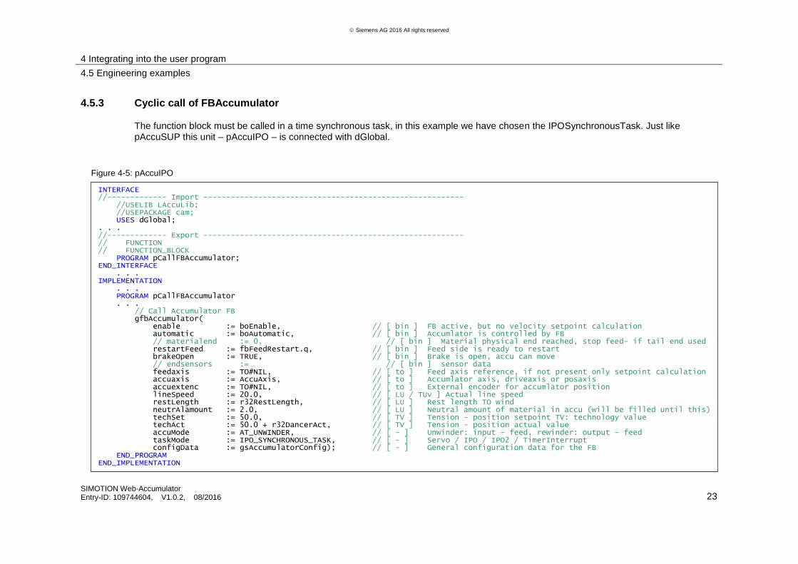
4.5.3 Cyclic call of FBAccumulator
The function block must be called in a time synchronous task, in this example we have chosen the IPOSynchronousTask. Just like pAccuSUP this unit – pAccuIPO – is connected with dGlobal.
INTERFACE //------------- Import --------------------------------------------------------- //USELIB LAccuLib; //USEPACKAGE cam; USES dGlobal; . . . //------------- Export --------------------------------------------------------- // FUNCTION // FUNCTION_BLOCK PROGRAM pCallFBAccumulator; END_INTERFACE . . . IMPLEMENTATION . . . PROGRAM pCallFBAccumulator . . . // Call Accumulator FB gfbAccumulator( enable := boEnable, // [ bin ] FB active, but no velocity setpoint calculation automatic := boAutomatic, // [ bin ] Accumlator is controlled by FB // materialend := 0, // [ bin ] Material physical end reached, stop feed- if tail end used restartFeed := fbFeedRestart.q, // [ bin ] Feed side is ready to restart brakeOpen := TRUE, // [ bin ] Brake is open, accu can move // endsensors := // [ bin ] sensor data feedaxis := TO#NIL, // [ to ] Feed axis reference, if not present only setpoint calculation accuaxis := AccuAxis, // [ to ] Accumlator axis, driveaxis or posaxis accuextenc := TO#NIL, // [ to ] External encoder for accumlator position lineSpeed := 20.0, // [ LU / TUv ] Actual line speed restLength := r32RestLength, // [ LU ] Rest length TO wind neutrAlamount := 2.0, // [ LU ] Neutral amount of material in accu (will be filled until this) techSet := 50.0, // [ TV ] Tension - position setpoint TV: technology value techAct := 50.0 + r32DancerAct, // [ TV ] Tension - position actual value accuMode := AT_UNWINDER, // [ - ] Unwinder: input - feed, rewinder: output - feed taskMode := IPO_SYNCHRONOUS_TASK, // [ - ] Servo / IPO / IPO2 / TimerInterrupt configData := gsAccumulatorConfig); // [ - ] General configuration data for the FB END_PROGRAM END_IMPLEMENTATION
Figure 4-5: pAccuIPO
4 Integrating into the user program
4.5 Engineering examples
SIMOTION Web-Accumulator Entry-ID: 109744604, V1.0.2, 08/2016 24
S
iem
en
s A
G 2
01
6 A
ll ri
gh
ts r
ese
rve
d
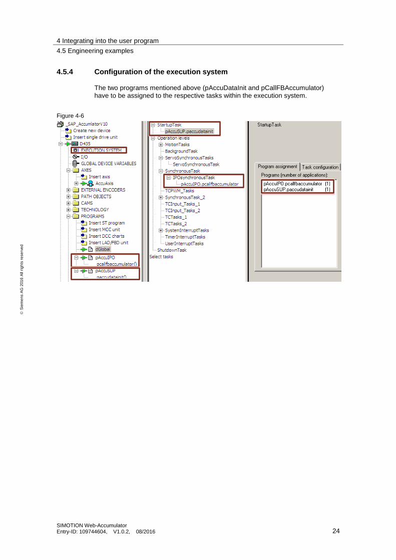
4.5.4 Configuration of the execution system
The two programs mentioned above (pAccuDataInit and pCallFBAccumulator) have to be assigned to the respective tasks within the execution system.
Figure 4-6

5 Program and function description
5.1 Information and warnings
SIMOTION Web-Accumulator Entry-ID: 109744604, V1.0.2, 08/2016 25
S
iem
en
s A
G 2
01
6 A
ll ri
gh
ts r
ese
rve
d
5 Program and function description
5.1 Information and warnings
WARNING
Before carrying-out changes
Uncontrolled, incorrect changes and modifications to core functions can result in death and severe bodily injury!
Before you carry-out changes to the components included in the core functions, you should get to know how the components function by referring to and reading the ST/MMC documentation.
Restrictions regarding support when changing components of the core functions
The Application Center can only provide support for core functions that have not been changed.
If changes have been made to the code, then support can no longer be provided for core functions.
This also applies for the revision and adaptation recommendations listed in this Chapter.
5.2 Data types
5.2.1 Overview
Enumeration types
Type declarations of enumeration types are provided for some of the input and output parameters of the function block. Various modes and properties can be pre-set using these parameters.
Data structures
The function block is mostly parameterized using data structures. These structures are described in detail.
5.2.2 Enumeration types
The following enumeration data types are defined and used in the application.
Table 5-1
Enumeration type name Contents
eAccumulatorModeType Defines the location of the accumulator unit.
Declared in: LAccuLib.dTypes
eAxisTUType Defines the time unit for axis velocity and acceleration.
Declared in: LAccuLib.dTypes
eAxisLUType Defines the length unit for axis position, velocity and acceleration.
Declared in: LAccuLib.dTypes
eDiameterLUType Defines the length unit for axis diameter.
Declared in: LAccuLib.dTypes

5 Program and function description
5.2 Data types
SIMOTION Web-Accumulator Entry-ID: 109744604, V1.0.2, 08/2016 26
S
iem
en
s A
G 2
01
6 A
ll ri
gh
ts r
ese
rve
d
Enumeration type name Contents
eFrictionCharModeType Defines the definition mode for the friction compensation.
Declared in: LAccuLib.dTypes
eFeedStateType Defines the actual application state (of feed axis).
Declared in: LAccuLib.dTypes
eAccumulatorModeType
Table 5-2
Element Description
AT_UNWINDER Accumulator is located between the unwinder and the converting process. The output speed of the accumulator is constant.
AT_REWINDER Accumulator is located between the converting process and the rewinder. The input speed of the accumulator is constant.
eAxisTUType
This data type is used to define the time unit for the axis acceleration and speed for the internal conversions.
Separate values can be used for acceleration and speed within the application for the same axis.
Table 5-3
Element Description
UNDEFINED Time unit is undefined, default value.
MINUTE Time unit is one minute, speed is defined as LU/min and acceleration is defined as LU/min2
SECOND Time unit is one second, speed is defined as LU/s and acceleration is defined as LU/s2
eAxisLUType
This data type is used to define the length unit for the axis. Same LU is used for position, speed and acceleration.
Table 5-4
Element Description
UNDEFINED Length unit is undefined, default value.
REV Only for DRIVEAXIS, where speed and acceleration is defined as revolution/TU. Has no direct interpretation as position.
M Length unit is one meter.
For linear POSAXIS or signals with linear attributes.
MM Length unit is one millimeter.
IN Length unit is one inch.
FT Length unit is one feet.
RAD Length unit is one radian. 1 rev = 2 PI rad
For rotary POSAXIS. DEG Length unit is one degree. 1 rev = 360
deg
GON Length unit is one gradian. 1 rev = 400 gon
5 Program and function description
5.2 Data types
SIMOTION Web-Accumulator Entry-ID: 109744604, V1.0.2, 08/2016 27
S
iem
en
s A
G 2
01
6 A
ll ri
gh
ts r
ese
rve
d
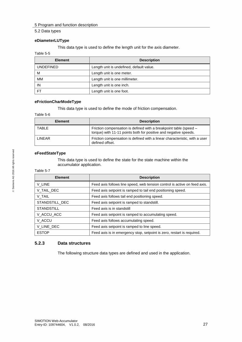
eDiameterLUType
This data type is used to define the length unit for the axis diameter.
Table 5-5
Element Description
UNDEFINED Length unit is undefined, default value.
M Length unit is one meter.
MM Length unit is one millimeter.
IN Length unit is one inch.
FT Length unit is one foot.
eFrictionCharModeType
This data type is used to define the mode of friction compensation.
Table 5-6
Element Description
TABLE Friction compensation is defined with a breakpoint table (speed – torque) with 11-11 points both for positive and negative speeds.
LINEAR Friction compensation is defined with a linear characteristic, with a user defined offset.
eFeedStateType
This data type is used to define the state for the state machine within the accumulator application.
Table 5-7
Element Description
V_LINE Feed axis follows line speed, web tension control is active on feed axis.
V_TAIL_DEC Feed axis setpoint is ramped to tail end positioning speed.
V_TAIL Feed axis follows tail end positioning speed.
STANDSTILL_DEC Feed axis setpoint is ramped to standstill.
STANDSTILL Feed axis is in standstill
V_ACCU_ACC Feed axis setpoint is ramped to accumulating speed.
V_ACCU Feed axis follows accumulating speed.
V_LINE_DEC Feed axis setpoint is ramped to line speed.
ESTOP Feed axis is in emergency stop, setpoint is zero, restart is required.
5.2.3 Data structures
The following structure data types are defined and used in the application.
5 Program and function description
5.2 Data types
SIMOTION Web-Accumulator Entry-ID: 109744604, V1.0.2, 08/2016 28
S
iem
en
s A
G 2
01
6 A
ll ri
gh
ts r
ese
rve
d
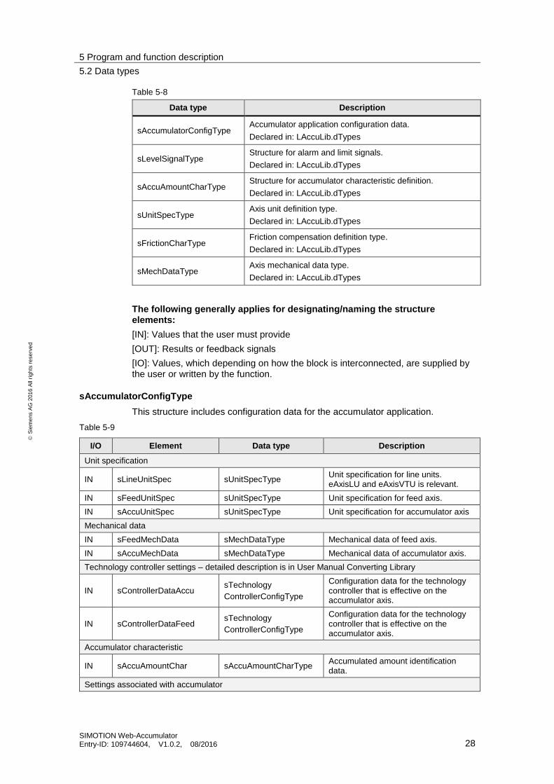
Table 5-8
Data type Description
sAccumulatorConfigType Accumulator application configuration data.
Declared in: LAccuLib.dTypes
sLevelSignalType Structure for alarm and limit signals.
Declared in: LAccuLib.dTypes
sAccuAmountCharType Structure for accumulator characteristic definition.
Declared in: LAccuLib.dTypes
sUnitSpecType Axis unit definition type.
Declared in: LAccuLib.dTypes
sFrictionCharType Friction compensation definition type.
Declared in: LAccuLib.dTypes
sMechDataType Axis mechanical data type.
Declared in: LAccuLib.dTypes
The following generally applies for designating/naming the structure elements:
[IN]: Values that the user must provide
[OUT]: Results or feedback signals
[IO]: Values, which depending on how the block is interconnected, are supplied by the user or written by the function.
sAccumulatorConfigType
This structure includes configuration data for the accumulator application.
Table 5-9
I/O Element Data type Description
Unit specification
IN sLineUnitSpec sUnitSpecType Unit specification for line units. eAxisLU and eAxisVTU is relevant.
IN sFeedUnitSpec sUnitSpecType Unit specification for feed axis.
IN sAccuUnitSpec sUnitSpecType Unit specification for accumulator axis
Mechanical data
IN sFeedMechData sMechDataType Mechanical data of feed axis.
IN sAccuMechData sMechDataType Mechanical data of accumulator axis.
Technology controller settings – detailed description is in User Manual Converting Library
IN sControllerDataAccu sTechnology
ControllerConfigType
Configuration data for the technology controller that is effective on the accumulator axis.
IN sControllerDataFeed sTechnology
ControllerConfigType
Configuration data for the technology controller that is effective on the accumulator axis.
Accumulator characteristic
IN sAccuAmountChar sAccuAmountCharType Accumulated amount identification data.
Settings associated with accumulator

5 Program and function description
5.2 Data types
SIMOTION Web-Accumulator Entry-ID: 109744604, V1.0.2, 08/2016 29
S
iem
en
s A
G 2
01
6 A
ll ri
gh
ts r
ese
rve
d
I/O Element Data type Description
IN u8PathCount USINT Number of material path used in the accumulator unit. Internally saved with the enable rising edge.
IN r32UpperSwLimit REAL [ac LU ] Upper software limit for accumulator position – if overridden, warning is initiated.
IN r32LowerSwLimit REAL [ac LU ] Lower software limit for accumulator position – if overridden, warning is initiated.
Settings associated with line
IN r32TailSpeed REAL
[li LU / vTU ] Tail end positioning speed. After the deceleration point is detected, feed axis will be decelerated to this speed until material end is detected.
IN r32AccuSpeed REAL
[li LU / vTU ] Accumulating speed offset added to the line speed setpoint, feed axis will be accelerated to this speed after the restart of the winder.
Fine adjustment settings (delays, corrections)
IN u32RestartDelay UDINT [ ms ] Delay time for feed restart after the coil change is signaled to the application.
IN u32WarningOnDelay UDINT
[ ms ] On-time delay for position warning signal output. If the axis position overrides the defined position levels for a shorter time, no signal is output.
IN u32WarningOffDelay UDINT
[ ms ] Time off delay for resetting the warning signal, after axis re-enters normal interval for position monitoring (with hysteresis).
IN r32WarningHyst REAL [ac LU ] Hysteresis value for resetting the warning signals (if software endsignals are used).
IN u32BrakePreOpenTime UDINT [ ms ] Brake for the accumulator axis will be opened prior to the detection of the deceleration point.
IN u32AccuPreEnableTime UDINT [ms] Adjustment time for enabling the accumulator axis prior to the opening, and after the closing of the brake.
IN r32AutoStopAdj REAL
[fe LU ] Adjustment length for automatic stop, subtracted from the rest length value, resulting in an earlier stop as the material end and leaving material on the coil.
IN r32FillStopAdj REAL [fe LU ] Like AutoStopAdj but for the deceleration from the accumulating speed to the line speed.
IN r32OutputChangeLimit REAL
[ac LU / vTU / TV ] Controller output limit for controller switchover. The web tension control is active on the accumulator axis while this axis is moving. The dancer or tension control will be re-activated on the feed axis, if
5 Program and function description
5.2 Data types
SIMOTION Web-Accumulator Entry-ID: 109744604, V1.0.2, 08/2016 30
S
iem
en
s A
G 2
01
6 A
ll ri
gh
ts r
ese
rve
d
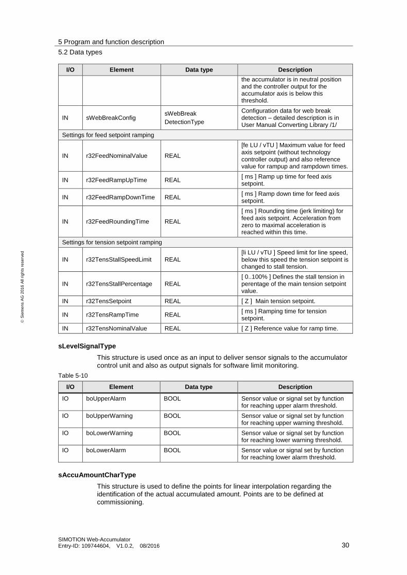
I/O Element Data type Description
the accumulator is in neutral position and the controller output for the accumulator axis is below this threshold.
IN sWebBreakConfig sWebBreak
DetectionType
Configuration data for web break detection – detailed description is in User Manual Converting Library /1/
Settings for feed setpoint ramping
IN r32FeedNominalValue REAL
[fe LU / vTU ] Maximum value for feed axis setpoint (without technology controller output) and also reference value for rampup and rampdown times.
IN r32FeedRampUpTime REAL [ ms ] Ramp up time for feed axis setpoint.
IN r32FeedRampDownTime REAL [ ms ] Ramp down time for feed axis setpoint.
IN r32FeedRoundingTime REAL
[ ms ] Rounding time (jerk limiting) for feed axis setpoint. Acceleration from zero to maximal acceleration is reached within this time.
Settings for tension setpoint ramping
IN r32TensStallSpeedLimit REAL [li LU / vTU ] Speed limit for line speed, below this speed the tension setpoint is changed to stall tension.
IN r32TensStallPercentage REAL [ 0..100% ] Defines the stall tension in perentage of the main tension setpoint value.
IN r32TensSetpoint REAL [ Z ] Main tension setpoint.
IN r32TensRampTime REAL [ ms ] Ramping time for tension setpoint.
IN r32TensNominalValue REAL [ Z ] Reference value for ramp time.
sLevelSignalType
This structure is used once as an input to deliver sensor signals to the accumulator control unit and also as output signals for software limit monitoring.
Table 5-10
I/O Element Data type Description
IO boUpperAlarm BOOL Sensor value or signal set by function for reaching upper alarm threshold.
IO boUpperWarning BOOL Sensor value or signal set by function for reaching upper warning threshold.
IO boLowerWarning BOOL Sensor value or signal set by function for reaching lower warning threshold.
IO boLowerAlarm BOOL Sensor value or signal set by function for reaching lower alarm threshold.
sAccuAmountCharType
This structure is used to define the points for linear interpolation regarding the identification of the actual accumulated amount. Points are to be defined at commissioning.
5 Program and function description
5.2 Data types
SIMOTION Web-Accumulator Entry-ID: 109744604, V1.0.2, 08/2016 31
S
iem
en
s A
G 2
01
6 A
ll ri
gh
ts r
ese
rve
d
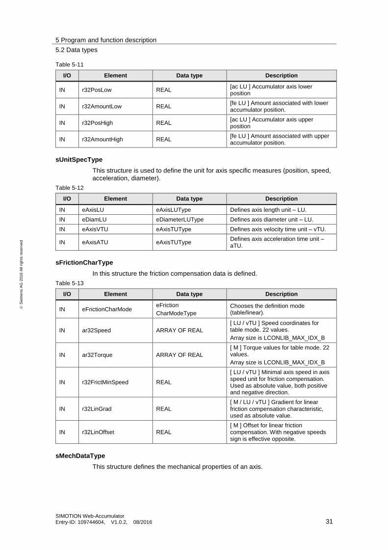
Table 5-11
I/O Element Data type Description
IN r32PosLow REAL [ac LU ] Accumulator axis lower position
IN r32AmountLow REAL [fe LU ] Amount associated with lower accumulator position.
IN r32PosHigh REAL [ac LU ] Accumulator axis upper position
IN r32AmountHigh REAL [fe LU ] Amount associated with upper accumulator position.
sUnitSpecType
This structure is used to define the unit for axis specific measures (position, speed, acceleration, diameter).
Table 5-12
I/O Element Data type Description
IN eAxisLU eAxisLUType Defines axis length unit – LU.
IN eDiamLU eDiameterLUType Defines axis diameter unit – LU.
IN eAxisVTU eAxisTUType Defines axis velocity time unit – vTU.
IN eAxisATU eAxisTUType Defines axis acceleration time unit – aTU.
sFrictionCharType
In this structure the friction compensation data is defined.
Table 5-13
I/O Element Data type Description
IN eFrictionCharMode eFriction
CharModeType
Chooses the definition mode (table/linear).
IN ar32Speed ARRAY OF REAL
[ LU / vTU ] Speed coordinates for table mode. 22 values.
Array size is LCONLIB_MAX_IDX_B
IN ar32Torque ARRAY OF REAL
[ M ] Torque values for table mode. 22 values.
Array size is LCONLIB_MAX_IDX_B
IN r32FrictMinSpeed REAL
[ LU / vTU ] Minimal axis speed in axis speed unit for friction compensation. Used as absolute value, both positive and negative direction.
IN r32LinGrad REAL [ M / LU / vTU ] Gradient for linear friction compensation characteristic, used as absolute value.
IN r32LinOffset REAL [ M ] Offset for linear friction compensation. With negative speeds sign is effective opposite.
sMechDataType
This structure defines the mechanical properties of an axis.
5 Program and function description
5.3 Function Block FBAccumulator
SIMOTION Web-Accumulator Entry-ID: 109744604, V1.0.2, 08/2016 32
S
iem
en
s A
G 2
01
6 A
ll ri
gh
ts r
ese
rve
d
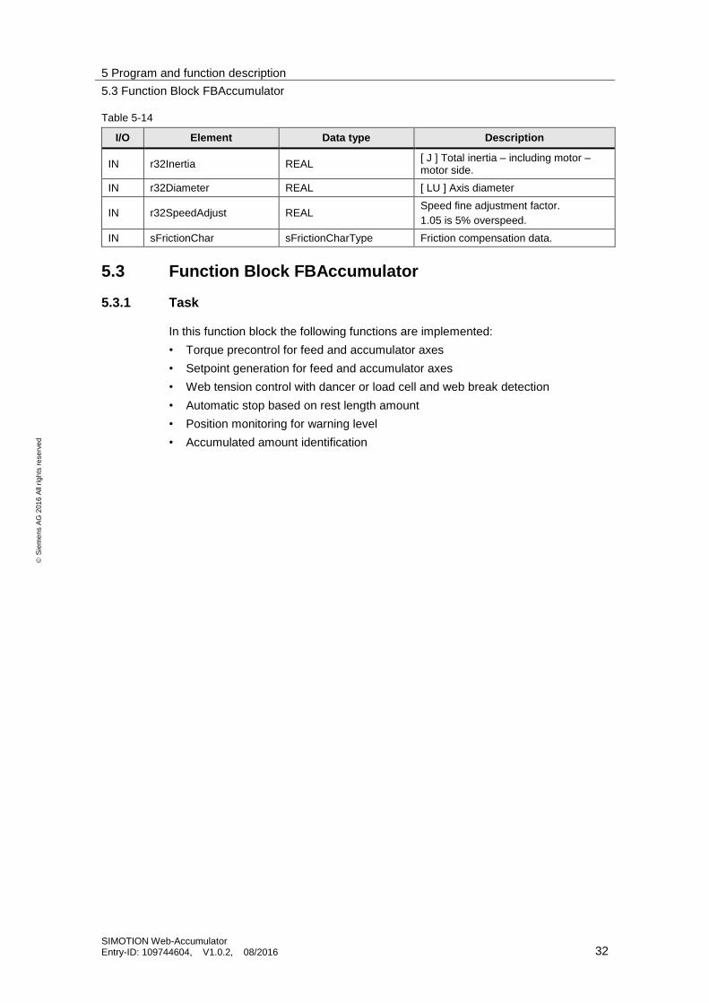
Table 5-14
I/O Element Data type Description
IN r32Inertia REAL [ J ] Total inertia – including motor – motor side.
IN r32Diameter REAL [ LU ] Axis diameter
IN r32SpeedAdjust REAL Speed fine adjustment factor.
1.05 is 5% overspeed.
IN sFrictionChar sFrictionCharType Friction compensation data.
5.3 Function Block FBAccumulator
5.3.1 Task
In this function block the following functions are implemented:
• Torque precontrol for feed and accumulator axes
• Setpoint generation for feed and accumulator axes
• Web tension control with dancer or load cell and web break detection
• Automatic stop based on rest length amount
• Position monitoring for warning level
• Accumulated amount identification
5 Program and function description
5.3 Function Block FBAccumulator
SIMOTION Web-Accumulator Entry-ID: 109744604, V1.0.2, 08/2016 33
S
iem
en
s A
G 2
01
6 A
ll ri
gh
ts r
ese
rve
d
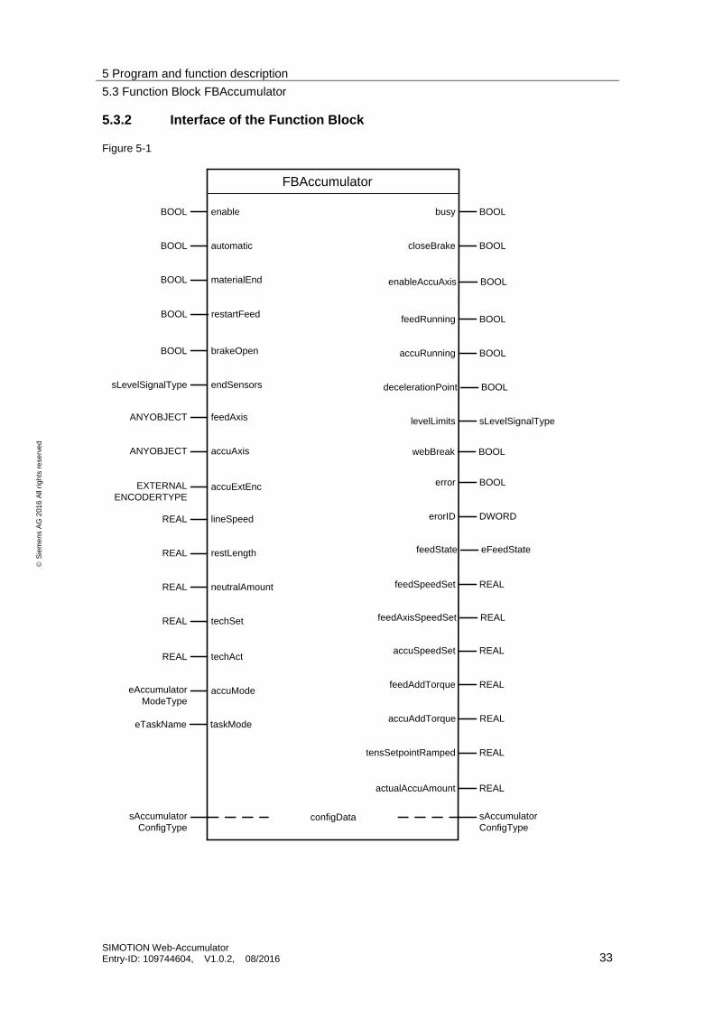
5.3.2 Interface of the Function Block
Figure 5-1
FBAccumulator
enableBOOL
automaticBOOL
materialEndBOOL
brakeOpenBOOL
busy BOOL
closeBrake BOOL
feedRunning BOOL
accuRunning BOOL
configDatasAccumulator
ConfigType
sAccumulator
ConfigType
endSensorssLevelSignalType
levelLimits sLevelSignalTypefeedAxisANYOBJECT
error BOOL
accuAxisANYOBJECT
erorID DWORD
accuExtEncEXTERNAL
ENCODERTYPE
feedSpeedSet REAL
lineSpeedREAL
accuSpeedSet REAL
restLengthREAL
feedAddTorque REAL
neutralAmountREAL
accuAddTorque REAL
techSetREAL
tensSetpointRamped REAL
techActREAL
actualAccuAmount REAL
accuModeeAccumulator
ModeType
taskModeeTaskName
restartFeedBOOL
enableAccuAxis BOOL
decelerationPoint BOOL
feedState eFeedState
feedAxisSpeedSet REAL
webBreak BOOL

5 Program and function description
5.3 Function Block FBAccumulator
SIMOTION Web-Accumulator Entry-ID: 109744604, V1.0.2, 08/2016 34
S
iem
en
s A
G 2
01
6 A
ll ri
gh
ts r
ese
rve
d
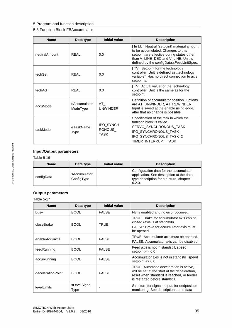
5.3.3 Block parameters
Input parameters
Table 5-15
Name Data type Initial value Description
enable BOOL FALSE
FALSE: FB deactivated completely
Rising edge: initialisation, and then active
TRUE: functions without automatic mode functions are active
Falling edge: FB will be disabled, motionIn interface disabled immediately.
automatic BOOL FALSE
TRUE: functions for automatic mode (feed and accumulator speed setpoint calculation, technology (dancer or tension) control ) are active
FALSE: functions or automatic mode are disabled. Feed speed setpoint is ramped to zero. Feed axis motion interfaces deactivated, after speed setpoint ramping is done. Accumulator axis stopped immediately.
materialEnd BOOL FALSE Rising edge: indicates the reach of the material end. Result is the deceleration of the feed axis to standstill.
restartFeed BOOL FALSE Rising edge: feed axis is restarted, feed axis state is switched to accumulating. Only effective if feed axis is in standstill.
brakeOpen BOOL FALSE
TRUE: The motor holding brake for the accumulator axis is open
FALSE: The motor holding brake for the accumulator axis is closed. If the brake is closed when the accumulator should be moving, a warning is output.
endSensors sLevelSignal
Type -
Structure for signal input, for endposition monitoring. See description at the data type description for structure, chapter 6.2.3.
feedAxis ANYOBJECT TO#NIL Object reference for the feed axis. Can be TO#NIL, DRIVEAXIS or POSAXIS. If present, must be enabled all the time.
accuAxis ANYOBJECT TO#NIL
Object reference for the accumulator axis. Can be DRIVEAXIS or POSAXIS. Must be enabled at start and when the enableAccuAxis output is true. If POSAXIS, must not be modulo.
accuExtEnc
EXTERNAL
ENCODER
TYPE
TO#NIL
Object reference for accumulator external encoder. Can be TO#NIL or EXTERNALENCODERTYPE. If TO#NIL (no external encoder is used) accuAxis must be a POSAXIS. Must not be modulo.
lineSpeed REAL 0.0 [ li LU / vTU ] Actual line speed setpoint. Unit is defined by the configData.sLineUnitSpec.
restLength REAL MAX_REAL [ fe LU ] Actual rest length to be wound. Unit is defined by the configData.sFeedUnitSpec.
5 Program and function description
5.3 Function Block FBAccumulator
SIMOTION Web-Accumulator Entry-ID: 109744604, V1.0.2, 08/2016 35
S
iem
en
s A
G 2
01
6 A
ll ri
gh
ts r
ese
rve
d
Name Data type Initial value Description
neutralAmount REAL 0.0
[ fe LU ] Neutral (setpoint) material amount to be accumulated. Changes to this setpoint are effective during states other than V_LINE_DEC and V_LINE. Unit is defined by the configData.sFeedUnitSpec.
techSet REAL 0.0
[ TV ] Setpoint for the technology controller. Unit is defined as „technology variable“. Has no direct connection to axis setpoints.
techAct REAL 0.0 [ TV ] Actual value for the technology controller. Unit is the same as for the setpoint.
accuMode eAccumulator
ModeType
AT_
UNWINDER
Definition of accumulator position. Options are AT_UNWINDER, AT_REWINDER. Input is saved at the enable rising edge, after that no change is possible.
taskMode eTaskName
Type
IPO_SYNCH
RONOUS_
TASK
Specification of the task in which the function block is called.
SERVO_SYNCHRONOUS_TASK
IPO_SYNCHRONOUS_TASK
IPO_SYNCHRONOUS_TASK_2
TIMER_INTERRUPT_TASK
Input/Output parameters
Table 5-16
Name Data type Initial value Description
configData sAccumulator
ConfigType -
Configuration data for the accumulator application. See description at the data type description for structure, chapter 6.2.3.
Output parameters
Table 5-17
Name Data type Initial value Description
busy BOOL FALSE FB is enabled and no error occurred.
closeBrake BOOL TRUE
TRUE: Brake for accumulator axis can be closed (axis is at standstill).
FALSE: Brake for accumulator axis must be opened.
enableAccuAxis BOOL FALSE TRUE: Accumulator axis must be enabled.
FALSE: Accumulator axis can be disabled.
feedRunning BOOL FALSE Feed axis is not in standstill, speed setpoint <> 0.0
accuRunning BOOL FALSE Accumulator axis is not in standstill, speed setpoint <> 0.0
decelerationPoint BOOL FALSE
TRUE: Automatic deceleration is active, will be set at the start of the deceleration, reset when standstill is reached, or feeder is restarted before standstill.
levelLimits sLevelSignal
Type - Structure for signal output, for endposition
monitoring. See description at the data

5 Program and function description
5.3 Function Block FBAccumulator
SIMOTION Web-Accumulator Entry-ID: 109744604, V1.0.2, 08/2016 36
S
iem
en
s A
G 2
01
6 A
ll ri
gh
ts r
ese
rve
d
Name Data type Initial value Description
type description for structure, chapter 6.2.3.
webBreak BOOL FALSE TRUE: Web break is detected.
FALSE: No web brake detected.
error BOOL FALSE FALSE: No error occurred
TRUE: Error occurred
errorID DWORD 16#0000_0000
Error identification, refer to error messages errorID < 16#000_8000: warning
errorID >= 16#0000_8000: error
feedState eFeedState
Type STANDSTILL
Actual state of feed axis within the application.
feedSpeedSet REAL 0.0
[ fe LU / vTU ] Speed setpoint for feed axis without web tension correction. This setpoint is not activated on the TO, if the TO is controlled by the FB. Unit is defined by the configData.sFeedUnitSpec.
feedAxisSpeedSet REAL 0.0
[ fe LU / vTU ] Speed setpoint for feed axis with web tension correction. This setpoint is activated on the TO, if the TO is controlled by the FB. Unit is defined by the configData.sFeedUnitSpec.
accuSpeedSet REAL 0.0 [ ac LU / vTU ] Speed setpoint for accumulator axis. Unit is defined by the configData.sAccuUnitSpec indirectly.
feedAddTorque REAL 0.0 [ fe M ] Additive (precontrol) torque for feed axis. Unit is defined by the configData.sFeedUnitSpec indirectly.
accuAddTorque REAL 0.0 [ ac M ] Additive (precontrol) torque for accumulator axis. Unit is defined by the configData.sAccuUnitSpec.
tensSetpoint
Ramped REAL 0.0
[ Z ] Ramped tension setpoint, unit is same, as tension setpoint in configData.r32TensSetpoint
actualAccuAmount REAL 0.0 [ fe LU ] Actual accumulated material amount. Unit is defined by the configData.sFeedUnitSpec.
5.3.4 Error messages
Table 5-18
Error ID Priority Description
16#xxxx_0xxxx Lowest priority Warning
16#xxxx_4xxx Low priority Warning, cannot be executed
16#xxxx_8xxx High priority Error, can no longer be executed
16#xxxx_Cxxx Highest priority Critical error
Errors
Error messages are displayed using the state of the error and errorID output: error = TRUE and errorID <> 16#0000_0000.
5 Program and function description
5.4 Function description
SIMOTION Web-Accumulator Entry-ID: 109744604, V1.0.2, 08/2016 37
S
iem
en
s A
G 2
01
6 A
ll ri
gh
ts r
ese
rve
d
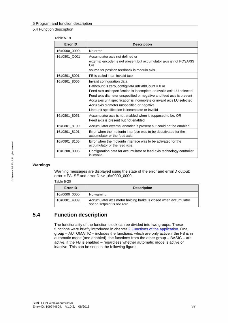
Table 5-19
Error ID Description
16#0000_0000 No error
16#0801_C001 Accumulator axis not defined or
external encoder is not present but accumulator axis is not POSAXIS OR
source for position feedback is modulo axis
16#0801_8001 FB is called in an invalid task
16#0801_8005 Invalid configuration data
Pathcount is zero, configData.u8PathCount = 0 or
Feed axis unit specification is incomplete or invalid axis LU selected
Feed axis diameter unspecified or negative and feed axis is present
Accu axis unit specification is incomplete or invalid axis LU selected
Accu axis diameter unspecified or negative
Line unit specification is incomplete or invalid
16#0801_8051 Accumulator axis is not enabled when it supposed to be. OR
Feed axis is present but not enabled.
16#0801_8100 Accumulator external encoder is present but could not be enabled
16#0801_8101 Error when the motionIn interface was to be deactivated for the accumulator or the feed axis.
16#0801_8105 Error when the motionIn interface was to be activated for the accumulator or the feed axis.
16#0208_8005 Configuration data for accumulator or feed axis technology controller is invalid.
Warnings
Warning messages are displayed using the state of the error and errorID output: error = FALSE and errorID <> 16#0000_0000.
Table 5-20
Error ID Description
16#0000_0000 No warning
16#0801_4009 Accumulator axis motor holding brake is closed when accumulator speed setpoint is not zero.
5.4 Function description
The functionality of the function block can be divided into two groups. These functions were briefly introduced in chapter 2 Functions of the application. One group – AUTOMATIC – includes the functions, which are only active if the FB is in automatic mode (and enabled), the functions from the other group – BASIC – are active, if the FB is enabled – regardless whether automatic mode is active or inactive. This can be seen in the following figure.

5 Program and function description
5.4 Function description
SIMOTION Web-Accumulator Entry-ID: 109744604, V1.0.2, 08/2016 38
S
iem
en
s A
G 2
01
6 A
ll ri
gh
ts r
ese
rve
d
Figure 5-2
FBAccumulator
BASIC
(enable = TRUE)
- monitoring of accumulator position for warning and alarm
levels (endposition monitoring)
- identification of the accumulated amount based on the actual
position of the accumulator (material amount identification)
- torque precontrol for accumulator and feed axes including
inertia and friction compensation
- ramping for tension setpoint signal (or any quantity which is
associated with web tension)
AUTOMATIC
(enable AND automatic = TRUE)
- web tension control with dancer roll or load cell as actual
value source and speed correction as effective system
input, web break detection
- rest length monitoring and coordination of coil change
- feed and accumulator speed setpoint calculation
- feed setpoint ramping
- speed setpoint activation on technology objects for feed
and accumulator axes
However, the accumulator position monitoring is one of the basic functions, there is no emergency reaction in basic mode, since axis control is inactive.
If no axis is specified as feedAxis, torque precontrol for the feed axis will not be calculated.
5.4.1 System of units
There are numerous quantities which depend on physical units – such as position, length, speed, acceleration, angular velocity, angular acceleration, torque, tension, moment of inertia, diameter. It is possible, that different axes and signals use different quantities. For example in most cases the line speed is defined as m/min, but the diameter for an axis defined in mm, the speed is in RPM. To have an unambiguous representation of these quantities the units have to be defined. Where signals, which can have different units – for example at accumulator speed setpoint calculation – first all quantities are converted to the standard internal SI units (m, s, rad, kg as base units) and then converted into target axis units.

5 Program and function description
5.4 Function description
SIMOTION Web-Accumulator Entry-ID: 109744604, V1.0.2, 08/2016 39
S
iem
en
s A
G 2
01
6 A
ll ri
gh
ts r
ese
rve
d
Axis units
In SIMOTION there are numerous possibilities to define axis units for different quantities. In this application not all of these combinations are supported. The following combination of units is possible:
Table 5-21
Axis type DRIVEAXIS POSAXIS ROT POSAXIS LIN NOAXIS
Position - LU LU LU
Velocity 1 / vTU LU / vTU LU / vTU LU / vTU
Acceleration 1 / aTU2 LU / aTU
2 LU / aTU
2 -
Possible LU rev rad, deg, gon m, mm, in, ft
Possible vTU/aTU s, min
Feature of quantites
Rotary
(angular velocity)
Diameter is used to calculate circumferential velocity and
acceleration from axis variables
Linear
(circumferential velocity)
Diameter is used to calculate angular velocity and acceleration from axis
variables
SI units rad, rad/s, rad/s2 m, m/s, m/s
2
Units which can be constructed with the use of Table 5-21 are available as axis units. One restriction applies: the same LU must be used for all axis quantities. TU can be chosen for speed and acceleration separately.
As line axis there is no technology object, which is connected to the accumulator function block, but some quantities and the actual line speed still have units. In this case the axis type NOAXIS applies. The same is true for feed related quantities, if no axis is parametrized at the feedAxis input.
Units of parameters
Various parameters of the accumulator can be associated with an axis. In this case the units used for the axis also define the units of these parameters.
In the type descriptions and the IO list of FBAccumulator the units are represented as [ac LU/vTU] for example. The abbreviations represent the following:
Prefixes:
• ac – unit is associated with the units of the accumulator axis
• li – unit is associated with the units of the line “axis”
• fe – unit is associated with the units of the feed axis
Units:
• vTU – time unit of velocity
• LU – length unit
– if axis has rotary features, LU of diameter
– if axis has linear features, LU of axis position
• M – unit is the unit of torque (see Table 6-22)
• J – unit is the unit of the moment of inertia (see Table 6-22)
The unit of torque and inertia depend on the LU of the diameter (DRIVEAXIS, POSAXIS ROT) or the LU of the position (NOAXIS, POSAXIS LIN) of the respective axis.

5 Program and function description
5.4 Function description
SIMOTION Web-Accumulator Entry-ID: 109744604, V1.0.2, 08/2016 40
S
iem
en
s A
G 2
01
6 A
ll ri
gh
ts r
ese
rve
d
Table 5-22
Definition LU Metric – m, mm US imperial – ft, in
Torque [M] N * m lbf * ft
Moment of inertia [J] kg * m2 lb * ft
2
Units without conversion
• TV – unit is the unit of the technology value (dancer position or tension), here no conversions are needed, unit is not to be set
• Z – unit is the tension setpoint unit (which is only ramped), here no conversion is needed, unit is not to be set.
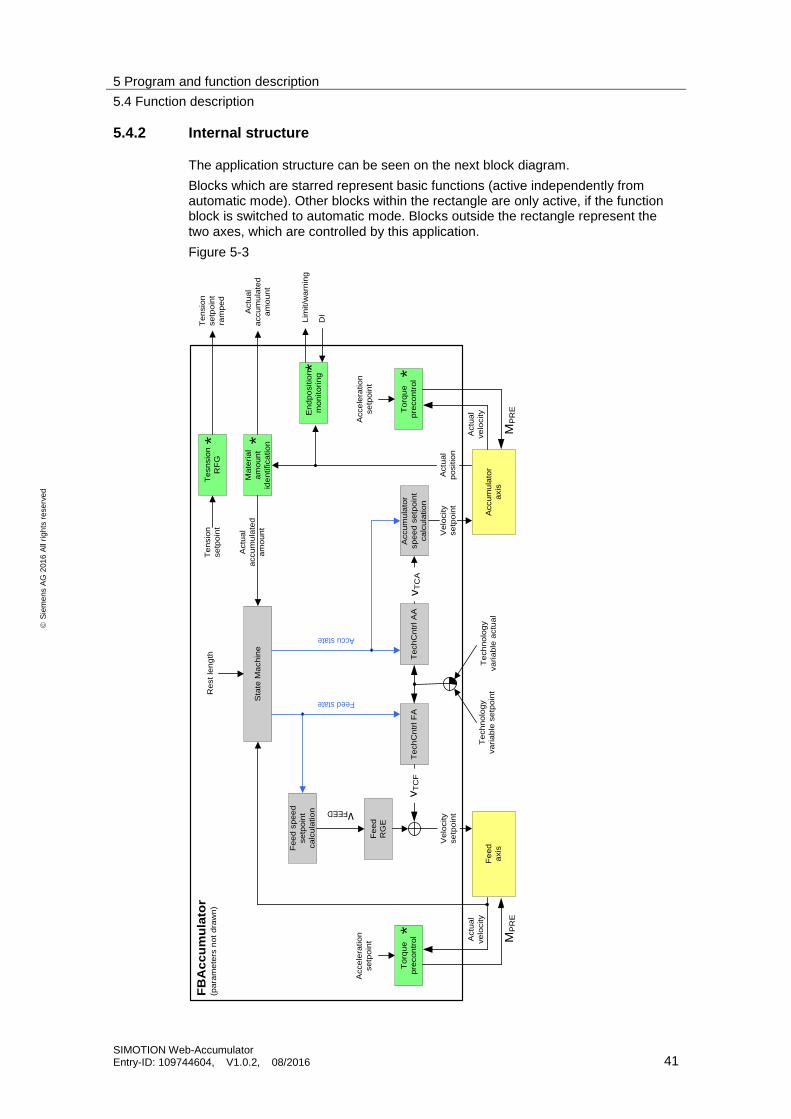
5 Program and function description
5.4 Function description
SIMOTION Web-Accumulator Entry-ID: 109744604, V1.0.2, 08/2016 41
S
iem
en
s A
G 2
01
6 A
ll ri
gh
ts r
ese
rve
d
5.4.2 Internal structure
The application structure can be seen on the next block diagram.
Blocks which are starred represent basic functions (active independently from automatic mode). Other blocks within the rectangle are only active, if the function block is switched to automatic mode. Blocks outside the rectangle represent the two axes, which are controlled by this application.
Figure 5-3
Te
ch
Cn
trl F
AT
ech
Cn
trl A
A
Te
ch
no
log
y
va
ria
ble
se
tpo
int
Accu
mu
lato
r
axis
vFEED
Ve
locity
se
tpo
int
Actu
al
po
sitio
n
Ma
teria
l
am
ou
nt
ide
ntifica
tio
n
To
rqu
e
pre
co
ntr
ol
Actu
al
ve
locity
MP
RE
Acce
lera
tio
n
se
tpo
int
En
dp
ositio
n
mo
nito
rin
gD
I
Lim
it/w
arn
ing
Te
ch
no
log
y
va
ria
ble
actu
al
Fe
ed
RG
E
vT
CF
Actu
al
accu
mu
late
d
am
ou
nt
Fe
ed
axis
To
rqu
e
pre
co
ntr
ol Actu
al
ve
locity
MP
RE
Ve
locity
se
tpo
int
Acce
lera
tio
n
se
tpo
int
Te
sn
sio
n
RF
G
Te
nsio
n
se
tpo
int
Te
nsio
n
se
tpo
int
ram
pe
d
Accu
mu
lato
r
sp
ee
d s
etp
oin
t
ca
lcu
latio
n
Fe
ed
sp
ee
d
se
tpo
int
ca
lcu
latio
n
Sta
te M
ach
ine
Re
st le
ng
th
Feed state
Accu state
vT
CA
Actu
al
accu
mu
late
d
am
ou
nt
FB
Ac
cu
mu
lato
r(p
ara
me
ters
no
t d
raw
n)
*
* *
**
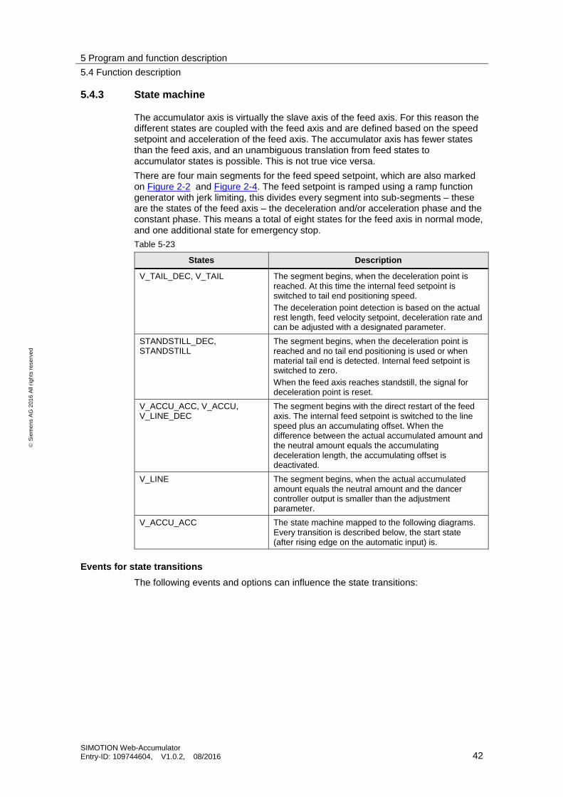
5 Program and function description
5.4 Function description
SIMOTION Web-Accumulator Entry-ID: 109744604, V1.0.2, 08/2016 42
S
iem
en
s A
G 2
01
6 A
ll ri
gh
ts r
ese
rve
d
5.4.3 State machine
The accumulator axis is virtually the slave axis of the feed axis. For this reason the different states are coupled with the feed axis and are defined based on the speed setpoint and acceleration of the feed axis. The accumulator axis has fewer states than the feed axis, and an unambiguous translation from feed states to accumulator states is possible. This is not true vice versa.
There are four main segments for the feed speed setpoint, which are also marked on Figure 2-2 and Figure 2-4. The feed setpoint is ramped using a ramp function generator with jerk limiting, this divides every segment into sub-segments – these are the states of the feed axis – the deceleration and/or acceleration phase and the constant phase. This means a total of eight states for the feed axis in normal mode, and one additional state for emergency stop.
Table 5-23
States Description
V_TAIL_DEC, V_TAIL The segment begins, when the deceleration point is reached. At this time the internal feed setpoint is switched to tail end positioning speed.
The deceleration point detection is based on the actual rest length, feed velocity setpoint, deceleration rate and can be adjusted with a designated parameter.
STANDSTILL_DEC, STANDSTILL
The segment begins, when the deceleration point is reached and no tail end positioning is used or when material tail end is detected. Internal feed setpoint is switched to zero.
When the feed axis reaches standstill, the signal for deceleration point is reset.
V_ACCU_ACC, V_ACCU, V_LINE_DEC
The segment begins with the direct restart of the feed axis. The internal feed setpoint is switched to the line speed plus an accumulating offset. When the difference between the actual accumulated amount and the neutral amount equals the accumulating deceleration length, the accumulating offset is deactivated.
V_LINE The segment begins, when the actual accumulated amount equals the neutral amount and the dancer controller output is smaller than the adjustment parameter.
V_ACCU_ACC The state machine mapped to the following diagrams. Every transition is described below, the start state (after rising edge on the automatic input) is.
Events for state transitions
The following events and options can influence the state transitions:

5 Program and function description
5.4 Function description
SIMOTION Web-Accumulator Entry-ID: 109744604, V1.0.2, 08/2016 43
S
iem
en
s A
G 2
01
6 A
ll ri
gh
ts r
ese
rve
d
Table 5-24
Event/Option Description
Deceleration point is reached The deceleration point is reached, when the material length (brake length), which will still be transported by the feed axis during the normal deceleration – deceleration is defined by the ramp parameters – equals to the rest length which can be wound on the coil – this is the restLength input.
This timing can be adjusted with the sConfigData.r32AutoStopAdj parameter. Positive adjustment values result in earlier detection of the deceleration point, meaning that there will be some material left on the unwinder or some free space on the rewinder. Negative adjustment value has an opposite effect.
Tail end positioning speed is used
Tail end positioning is used, if the sConfigData.r32tailSpeed parameter is positive
Material end is reached (sensor) When material end is detected, this is signaled with the materialEnd input
Feed axis restart Feed axis is restarted by the input signal restartFeed. The restart of the axis can be delayed using the sConfigData.u32restartDelay parameter.
Line speed deceleration point is reached
The line speed deceleration point is reached, when the material length (brake length), which will still be transported by the feed axis during deceleration from the accumulating speed to line speed – deceleration is defined by the ramp parameters – equals to amount difference between the actualAccuAmount and neutralAmount.
This timing can be adjusted with the configData.r32fillStopAdj parameter. Positive adjustment values result in earlier detection of the line speed deceleration point, meaning that there will be less material accumulated than the neutral amount. Negative adjustment value has an opposite effect. Trigger is internal for the transition
Accumulated material amount is in neutral interval
The neutral interval detection depends on the accuMode and neutralAmount inputs, and the actual accumulated amount - actualAccuAmount.
accuMode = AT_UNWINDER: actualAccuAmount >= neutralAmount
accuMode = AT_REWINDER: actualAccuAmount <= neutralAmount
Feed setpoint ramping finished Setpoint ramping is finished, if the input of the feed axis setpoint ramp function generator equals the ramped output.
Technology controller output is ready for switch
Since the web tension control is switched between the accumulator and feed axes, the changeovers must be smooth. For the switchover from accumulator to feed axis a threshold is defined – sConfigData.r32OutputChangeLimit – when the technology controller output drops below this value, switchover takes place.
Emergency stop Emergency stop is triggered by the signals endSensors.boUpperAlarm and endSensors.boLowerAlarm for reaching the hardware endposition.

5 Program and function description
5.4 Function description
SIMOTION Web-Accumulator Entry-ID: 109744604, V1.0.2, 08/2016 44
S
iem
en
s A
G 2
01
6 A
ll ri
gh
ts r
ese
rve
d
Calculation of brake length
The calculation of the brake length does not consider the settings for jerk limiting while assuming constant deceleration. This can be represented as a triangle, where the brake length is the area of the triangle.
Figure 5-4
time
ve
locity
Δv
tDEC
The following equations are true:
ondeceleratitv DEC
2_
vtlengthbrake DEC
And therefore
ondecelerati
vlengthbrake
2_
2
For the detection of the deceleration point v = vLINE, for the detection of the line
speed deceleration point v = vACCU
Transition matrix
The following matrix shows all possible transitions, transitions are grouped based on the actual state and the trigger events. Transitions are divided into two groups, regular and irregular transitions.
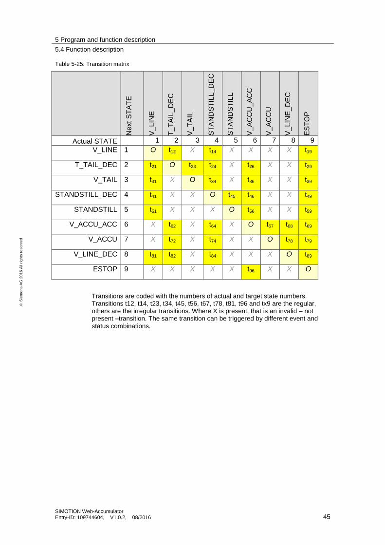
5 Program and function description
5.4 Function description
SIMOTION Web-Accumulator Entry-ID: 109744604, V1.0.2, 08/2016 45
S
iem
en
s A
G 2
01
6 A
ll ri
gh
ts r
ese
rve
d
Table 5-25: Transition matrix
Ne
xt
ST
AT
E
V_
LIN
E
T_T
AIL
_D
EC
V_
TA
IL
ST
AN
DS
TIL
L_
DE
C
ST
AN
DS
TIL
L
V_
AC
CU
_A
CC
V_
AC
CU
V_
LIN
E_
DE
C
ES
TO
P
Actual STATE 1 2 3 4 5 6 7 8 9
V_LINE 1 O t12 X t14 X X X X t19
T_TAIL_DEC 2 t21 O t23 t24 X t26 X X t29
V_TAIL 3 t31 X O t34 X t36 X X t39
STANDSTILL_DEC 4 t41 X X O t45 t46 X X t49
STANDSTILL 5 t51 X X X O t56 X X t59
V_ACCU_ACC 6 X t62 X t64 X O t67 t68 t69
V_ACCU 7 X t72 X t74 X X O t78 t79
V_LINE_DEC 8 t81 t82 X t84 X X X O t89
ESTOP 9 X X X X X t96 X X O
Transitions are coded with the numbers of actual and target state numbers. Transitions t12, t14, t23, t34, t45, t56, t67, t78, t81, t96 and tx9 are the regular, others are the irregular transitions. Where X is present, that is an invalid – not present –transition. The same transition can be triggered by different event and status combinations.
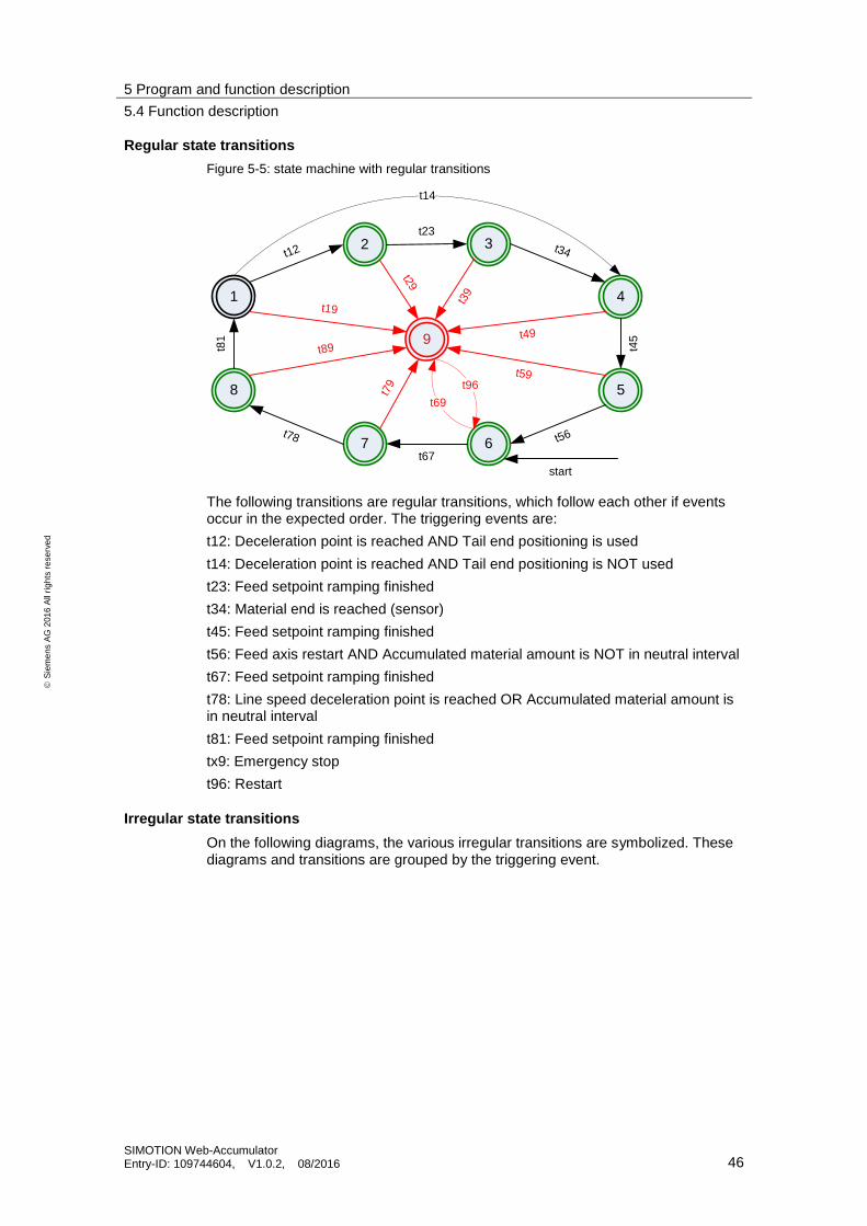
5 Program and function description
5.4 Function description
SIMOTION Web-Accumulator Entry-ID: 109744604, V1.0.2, 08/2016 46
S
iem
en
s A
G 2
01
6 A
ll ri
gh
ts r
ese
rve
d
Regular state transitions
Figure 5-5: state machine with regular transitions
8
t81
1
5
4
2 3
7 6t78
t67
t56
t23
t34
t45
t12
t19
t89
t79
t59
t49
t39
t29
t14
t96
t69
start
9
The following transitions are regular transitions, which follow each other if events occur in the expected order. The triggering events are:
t12: Deceleration point is reached AND Tail end positioning is used
t14: Deceleration point is reached AND Tail end positioning is NOT used
t23: Feed setpoint ramping finished
t34: Material end is reached (sensor)
t45: Feed setpoint ramping finished
t56: Feed axis restart AND Accumulated material amount is NOT in neutral interval
t67: Feed setpoint ramping finished
t78: Line speed deceleration point is reached OR Accumulated material amount is in neutral interval
t81: Feed setpoint ramping finished
tx9: Emergency stop
t96: Restart
Irregular state transitions
On the following diagrams, the various irregular transitions are symbolized. These diagrams and transitions are grouped by the triggering event.

5 Program and function description
5.4 Function description
SIMOTION Web-Accumulator Entry-ID: 109744604, V1.0.2, 08/2016 47
S
iem
en
s A
G 2
01
6 A
ll ri
gh
ts r
ese
rve
d
Transitions with asynchronous feed restart and reach of neutral amount
Figure 5-6: irregular transitions for feed axis restart and early reach of neutral position
8
1
5
4
2 3
7 6
t46
t26 t36
t68
The following transitions are irregular transitions. The triggering events are:
t26, t36, t46: Feed axis restart AND Accumulated material amount is NOT in neutral interval
t68: Line speed deceleration point is reached OR Accumulated material amount is in neutral interval
Transitions with feed restart in neutral interval
Figure 5-7: feed axis is restarted, but accumulator is in neutral interval
8
1
5
4
2 3
7 6
t51
t41
t31t21
The following transitions are irregular transitions. The triggering events are:
t21, t31, t41, t51: Feed axis restart AND Accumulated material amount is in neutral interval
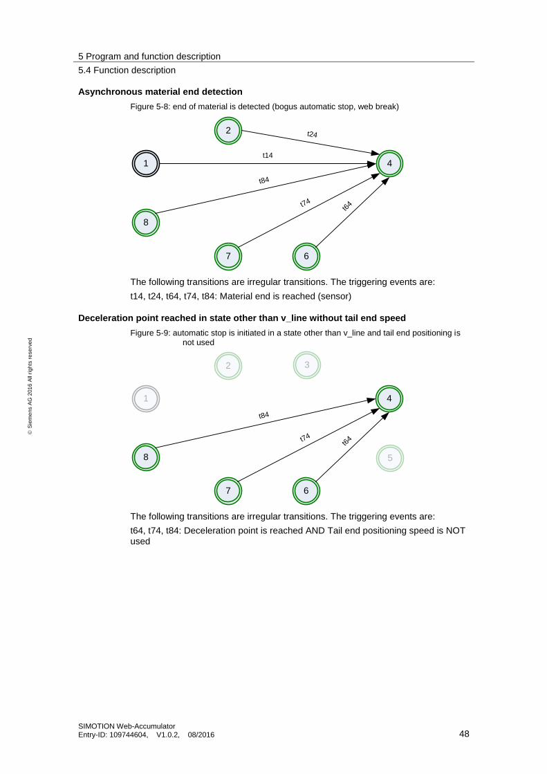
5 Program and function description
5.4 Function description
SIMOTION Web-Accumulator Entry-ID: 109744604, V1.0.2, 08/2016 48
S
iem
en
s A
G 2
01
6 A
ll ri
gh
ts r
ese
rve
d
Asynchronous material end detection
Figure 5-8: end of material is detected (bogus automatic stop, web break)
8
1 4
2
7 6
t24
t14
t84
t74t6
4
The following transitions are irregular transitions. The triggering events are:
t14, t24, t64, t74, t84: Material end is reached (sensor)
Deceleration point reached in state other than v_line without tail end speed
Figure 5-9: automatic stop is initiated in a state other than v_line and tail end positioning is not used
5
3
8
1 4
2
7 6
t84
t74t6
4
The following transitions are irregular transitions. The triggering events are:
t64, t74, t84: Deceleration point is reached AND Tail end positioning speed is NOT used
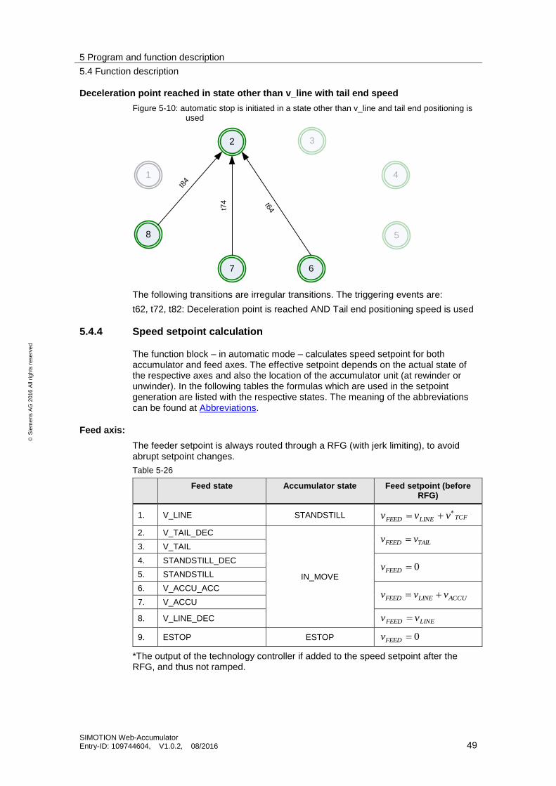
5 Program and function description
5.4 Function description
SIMOTION Web-Accumulator Entry-ID: 109744604, V1.0.2, 08/2016 49
S
iem
en
s A
G 2
01
6 A
ll ri
gh
ts r
ese
rve
d
Deceleration point reached in state other than v_line with tail end speed
Figure 5-10: automatic stop is initiated in a state other than v_line and tail end positioning is used
5
3
8
1 4
2
7 6
t84
t74 t64
The following transitions are irregular transitions. The triggering events are:
t62, t72, t82: Deceleration point is reached AND Tail end positioning speed is used
5.4.4 Speed setpoint calculation
The function block – in automatic mode – calculates speed setpoint for both accumulator and feed axes. The effective setpoint depends on the actual state of the respective axes and also the location of the accumulator unit (at rewinder or unwinder). In the following tables the formulas which are used in the setpoint generation are listed with the respective states. The meaning of the abbreviations can be found at Abbreviations.
Feed axis:
The feeder setpoint is always routed through a RFG (with jerk limiting), to avoid abrupt setpoint changes.
Table 5-26
Feed state Accumulator state Feed setpoint (before RFG)
1. V_LINE STANDSTILL TCFLINEFEED vvv
2. V_TAIL_DEC
IN_MOVE
TAILFEED vv 3. V_TAIL
4. STANDSTILL_DEC 0FEEDv
5. STANDSTILL
6. V_ACCU_ACC ACCULINEFEED vvv
7. V_ACCU
8. V_LINE_DEC LINEFEED vv
9. ESTOP ESTOP 0FEEDv
*The output of the technology controller if added to the speed setpoint after the RFG, and thus not ramped.
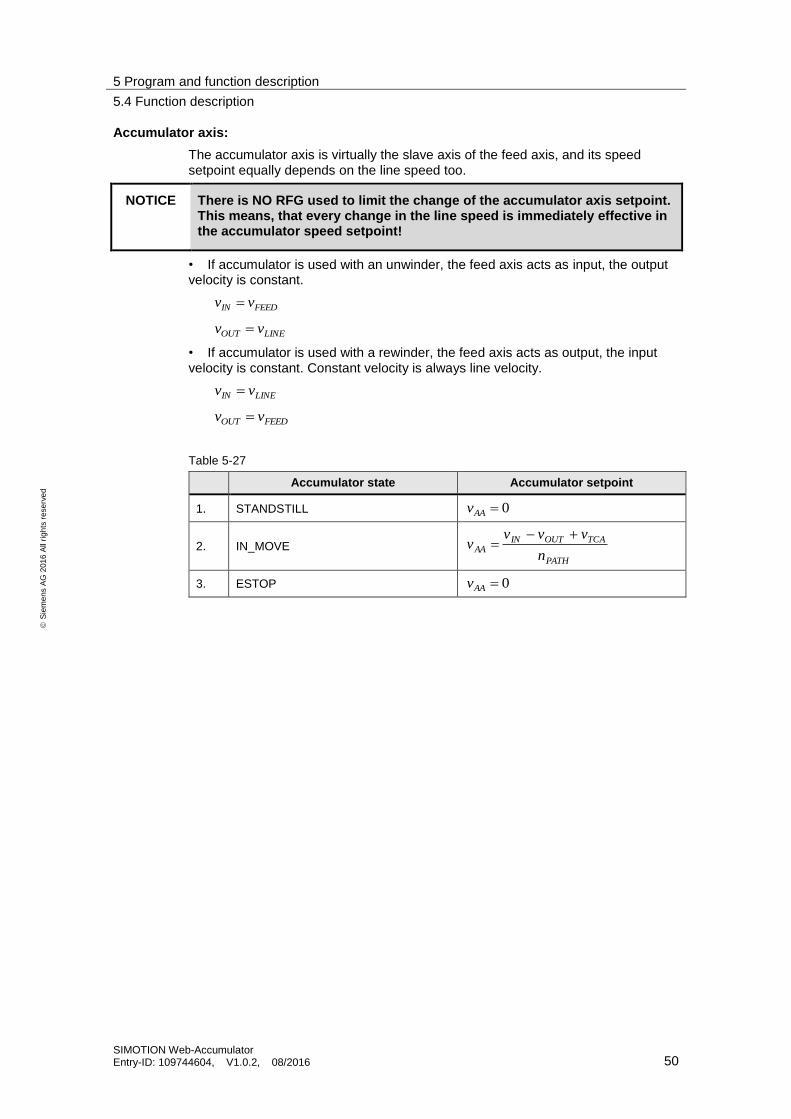
5 Program and function description
5.4 Function description
SIMOTION Web-Accumulator Entry-ID: 109744604, V1.0.2, 08/2016 50
S
iem
en
s A
G 2
01
6 A
ll ri
gh
ts r
ese
rve
d
Accumulator axis:
The accumulator axis is virtually the slave axis of the feed axis, and its speed setpoint equally depends on the line speed too.
NOTICE There is NO RFG used to limit the change of the accumulator axis setpoint. This means, that every change in the line speed is immediately effective in the accumulator speed setpoint!
• If accumulator is used with an unwinder, the feed axis acts as input, the output velocity is constant.
FEEDIN vv
LINEOUT vv
• If accumulator is used with a rewinder, the feed axis acts as output, the input velocity is constant. Constant velocity is always line velocity.
LINEIN vv
FEEDOUT vv
Table 5-27
Accumulator state Accumulator setpoint
1. STANDSTILL 0AAv
2. IN_MOVE PATH
TCAOUTINAA
n
vvvv
3. ESTOP 0AAv

5 Program and function description
5.4 Function description
SIMOTION Web-Accumulator Entry-ID: 109744604, V1.0.2, 08/2016 51
S
iem
en
s A
G 2
01
6 A
ll ri
gh
ts r
ese
rve
d
5.4.5 Timing diagrams
Figure 5-11: timing without error and with tail end positioning speed
1
0
1
0
1
0
1
0
1
0
enable
(IN)
automatic
(IN)
materialEnd
(IN)
restart
Feed
(IN)
error
(OUT)
closeBrake
(OUT)
1
0
1
0
busy
(OUT)
feed
Running
(OUT)
1
0
accu
Running
(OUT)
1
0
deceleration
Point
(OUT)
1
0
feedState
(internal) 5 678 1 2 3 4 5 6 7 8 1 5
(b1)
(c)
(e)
(d)
(a)
(f1)
(g)
enableAccu
Axis
(OUT)
1
0
(b2) (f2)
(a) After entering automatic mode, first state is V_ACCU_ACC (6) to reach neutral amount
(b1) Deceleration point was detected, brake was pre-opened, continue to tail end speed.
(b2) Accumulator axis is to be enabled prior to brake opening.
(c) Material end was detected, continue to standstill
(d) Feed axis reached standstill
(e) feed axis is restarted
(f1) Neutral amount was reached
(f2) Accumulator axis can be disabled after brake closing
(g) Feed axis setpoint is ramped to zero after falling edge of automatic.
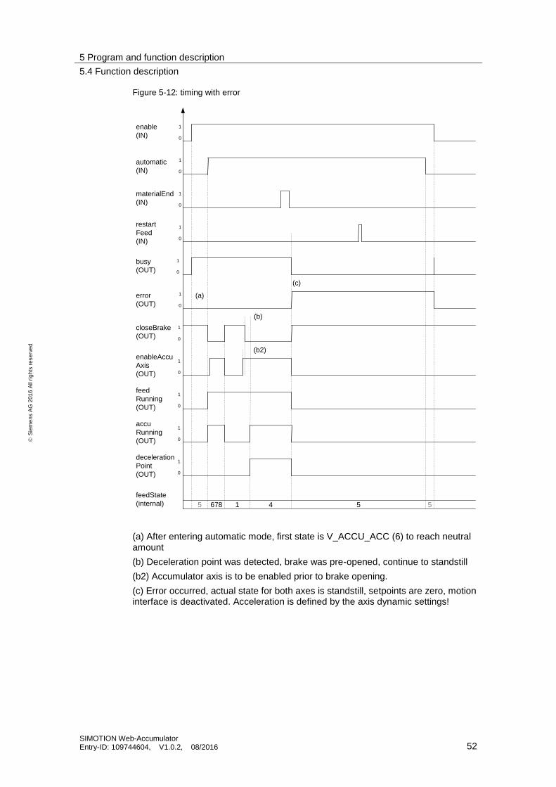
5 Program and function description
5.4 Function description
SIMOTION Web-Accumulator Entry-ID: 109744604, V1.0.2, 08/2016 52
S
iem
en
s A
G 2
01
6 A
ll ri
gh
ts r
ese
rve
d
Figure 5-12: timing with error
1
0
1
0
1
0
1
0
1
0
enable
(IN)
automatic
(IN)
materialEnd
(IN)
restart
Feed
(IN)
error
(OUT)
closeBrake
(OUT)
1
0
1
0
busy
(OUT)
feed
Running
(OUT)
1
0
accu
Running
(OUT)
1
0
deceleration
Point
(OUT)
1
0
feedState
(internal) 5 678 1 4 5 5
(b)
(c)
(a)
enableAccu
Axis
(OUT)
1
0
(b2)
(a) After entering automatic mode, first state is V_ACCU_ACC (6) to reach neutral amount
(b) Deceleration point was detected, brake was pre-opened, continue to standstill
(b2) Accumulator axis is to be enabled prior to brake opening.
(c) Error occurred, actual state for both axes is standstill, setpoints are zero, motion interface is deactivated. Acceleration is defined by the axis dynamic settings!

6 General information on the application
6.1 Scope of supply
SIMOTION Web-Accumulator Entry-ID: 109744604, V1.0.2, 08/2016 53
S
iem
en
s A
G 2
01
6 A
ll ri
gh
ts r
ese
rve
d
6 General information on the application
6.1 Scope of supply
The package „Web Accumulator with SIMOTION„ comprises the following:
• LAccuLib SIMOTION SCOUT library exported in XML format
• Sample ST source files for Startup task, global variable declaration and FBAccumulator call
• Documentation in english language
6.2 Abbreviations
Table 6-1
Name Description
AA Accumulator axis
aTU Time unit for acceleration
FA Feed axis
FB Function block
FC Function
lbf Pound-Force
Lib Library
LU Length unit
MPRE Precontrol torque
nPATH Accumulator path count
POU Program organisation unit
RFG Ramp function generator
RGE Ramp function generator with jerk limiting
SAP Standard Application
SCOUT SIMOTION Controlling with Optimized Usability Toolbox
SI Le Système International d’Unités – International system of units
ST Structured text (IEC 61131-3 Standard programming language)
TO Technology object
TU Time unit
vAA velocity of the accumulator axis, zero in standstill
vACCU velocity offset for accumulator fill/depletion
vFEED feed axis velocity, variable
vIN accumulator input velocity
vLINE line velocity, constant
vOUT accumulator output velocity
vTAIL tail end positioning velocity
vTCA technology controller output for accumulator axis

6 General information on the application
6.2 Abbreviations
SIMOTION Web-Accumulator Entry-ID: 109744604, V1.0.2, 08/2016 54
S
iem
en
s A
G 2
01
6 A
ll ri
gh
ts r
ese
rve
d
Name Description
vTCF technology controller output for feed axis
vTU Time unit for velocity/speed
XML eXtensible Markup Language

7 Related literature
SIMOTION Web-Accumulator Entry-ID: 109744604, V1.0.2, 08/2016 55
S
iem
en
s A
G 2
01
6 A
ll ri
gh
ts r
ese
rve
d
7 Related literature
Table 7-1
Topic
\1\ Siemens Industry Online Support
https://support.industry.siemens.com
\2\ Download page of this entry https://support.industry.siemens.com/cs/ww/en/view/109744604
\3\ Converting Library
User Manual Converting Library (LConLib)
https://support.industry.siemens.com/cs/ww/en/view/48805235
8 Contact Siemens AG
Digital Factory
DF FA PMA APC
Frauenauracher Strasse 80
91056 Erlangen
Germany
mailto: [email protected]
9 History
Table 9-1
Version Date Modifications
V 1.0.0 03/2009 First version
V 1.0.1 07/2009 minor changes in consistency
V 1.0.2 08/2016 compatibility for LConLib V2.x.x