manitou-answer 2001 sx service manual -...
TRANSCRIPT

ANSWER PRECISION SUSPENSIONCONGRATULATIONS FOR CHOOSING THE LATEST STATE OF THE ART MOUNTAIN BIKE SUSPENSION FORKAVAILABLE. THE 2001 SX FORK MODELS HAVE STATE OF THE ART MCU/SPRING COMPRESSION SYS-TEMS. THE SX SERIES ALL USE THE NEW TWIN PISTON CARTRIDGE SYSTEM (TPC) THAT SURPASS ALLOTHER TYPES OF OIL DAMPED SYSTEM IN PERFORMANCE AND DURABILITY.
Your 2001 SX Fork is fully assembled and ready to be installed onto your bicycle and comesequipped with a 1 1/8 threadless steer tube. 2001 SX’s are available with the V-Brake cable hang-erless archs.
CONSUMER SAFETY INFORMATION
GENERAL WARNING: Bicycling is a hazardous activity that requires that the rider stay in controlof his or her bicycle at all times. Reading this manual entirely and properly maintaining yourbicycle and suspension fork will reduce the possibility of injury or death. Prior to riding yourbicycle, you should inspect your suspension fork to ensure that no damage has occurred duringthe course of riding. Do not ride your bicycle if the fork shows any signs of bending, cracking,leaking, or if it is missing any of the originally supplied components. Any fall from your bicyclecan result in serious injury or even death. Following these instructions can help you reduce therisk of being injured. If you are a moderate or aggressive off-road rider, or ride at least three times a week overrough terrain, Answer recommends returning your suspension fork every 2 years for a thoroughinspection and update. Take your fork to a Manitou authorized dealer who can arrange for ship-ment to Answer Products, or you may call Answer at (661) 257-4411 to have your fork shippeddirectly.
IMPORTANT: 2001 SX Forks are off road forks and as such, do not come with the reflectors installedfor on road use. Reflector bracket kit P/N 85-3674 is available through your dealer. Have your deal-er or mechanic install the kit to meet the Consumer Product Safety Commission’s (C.P.S.C.)Requirements for Bicycles if the fork is going to be used on public roads at any time. If you havequestions regarding C.P.S.C. Standards contact your dealer.
1. Never remove or have the steer tube or stanchions (inner legs) removed from the crown. Thesteer tube and stanchions are press fit assembled at the factory. Pressing them out will perma-nently damage the crown, steer tube, and stanchions beyond repair and render them unsafefor any continued use.
2. Never attempt to thread a threadless steer tube. Machining threads will weaken the steer tubeand cause an unsafe condition. The only safe thing to do is to obtain the proper crown/steererfrom your dealer.
3. Any other alterations or modifications to your fork should be considered unsafe. ContactAnswer Products Technical Support at (661) 257-4411 prior to modifying your fork in any wayfor safety information.
4. Do not use any Manitou fork if any parts appear to be broken, bent, cracked, or damaged.Contact your dealer or Answer Products Technical Support. If you have any questions concern-ing the integrity, condition, or safe operation of your fork.
5. Answer Products recommends that you periodically inspect your fork for wear and damage.Inspect the crown, stanchions, and outer leg dropout, and brake arch areas for cracks or dam-age. Before every ride, check to ensure that the proper preload exists.
2001 SX SERVICE MANUAL

WARRANTY INFORMATIONAny Answer Products fork found by the factory to be defective in materials and/or workmanshipwithin one year from the date of purchase will be repaired or replaced at the option of the manu-facturer, free of charge, when received at the factory, freight prepaid. This warranty does notcover breakage, bending, or damage that may result from crashes or falls. This warranty does notcover any fork that has been modified, subject to misuse, or whose serial number has been altered,defaced or removed. This warranty does not cover paint damage. Any modifications made by theuser will render the warranty null and void. This warranty is expressly in lieu of all other war-ranties, and any implied are limited in duration to the same duration as the expressed warrantyherein. Answer Products shall not be liable for any incidental or consequential damages.
If for any reason warranty work is necessary, return the fork to the place of purchase. In the USA,dealers should call Answer Products for a return authorization number (RA#). At that time, instruc-tions for repair, return, or replacement shall be given. Customers in countries other than USAshould contact their dealer or local distributor.
INSTALLATION INSTRUCTIONS Ensure that the proper steer tube has been delivered on your fork. The steer tube may need to becut to length to fit your bicycle head tube. If you are not familiar with this procedure, or do nothave the proper tools to cut the steer tube, it is recommended that you seek a dealer with a quali-fied bicycle mechanic to perform installation.
WARNING: The steer tube and stanchions (inner legs) are a one time precision press fit at thefactory and cannot be removed from the crown. Replacement of the entire crown/steererassembly must be done to change steer tube lengths or diameters. Removing and replacing thesteer tube or stanchions will result in an unsafe condition and should never be done.
1 Remove old fork from bicycle.2 Measure and cut the steer tube to the same length as the old fork.3 Remove crown race from old fork and press onto steerer until seated on crown. Figure 14 Clean and grease headset bearings and races of bicycle.5 Install lower bearings on fork crown race.6 Insert steer tube into head tube of frame.7 Install upper bearings, spacers, and stem.8 Install stem cap, adjust, and tighten headset
per manufacture’s instructions.
Montaggio dell' anello della testa
FIG 1:
Installation du jeu de direction
Race installation
InstalacÛ del anilloEinbau des Laufrings
ARANDELA DE LA DIRECCIONCONE DE JEU DE DIRECTION
GABELBR‹CKEN-LAUFRING
ANELLO DELLIA TESTA
CROWN RACE
Modelo de horquilla Espacio libre mÌnimoModÈle de fourcheModello di forcella
80mm travel forks
Spazio libero minimo
3.26" (83 mm)
Jeu minimum
FIG 2:Minimum Tire Clearance
GabelmodellFork model
MindestabstandMinimum clearance
MINIMUM CLEARANCE
JUE MINIMUMESPACIO LIBRE MINIMO
SPAZIO LIBERO MINIMO
MINDESTABSTAND

9 Torque stem handlebar pinch screw and stem clamping system to manufacturer’s instructions.10 Install cantilever brakes and adjust per manufacturer’s instructions.Note: All 2001 SX forks are equipped with a secondary catch dropout.11 Adjust front wheel quick release to clear the 0.275 (7mm) thick secondary catch dropout. The
quick release must be tightened after it is properly seated into the dropout counter bores.Ensure that there is adequate thread engagement (4 or more threads with the release adjustedto lock) due to the wide adjustment. Install front wheel to bicycle per manufacturer’s specifi-cation.
12 Install brake cable per manufacturer’s instructions.
WARNING: When installing the wheel or any new tire, check the minimum tire clearance.Measure from the highest point on the tire to the bottom of the crown. The minimum clearanceallowed for 80mm travel fork models are 3.26(83mm) and for the 100mm travel fork model4.05 (103mm). Any less clearance can result in an accident with the possibility of serious injuryor death. Figure 2
SPARE PARTS: Table 1Spare parts can be ordered through your local dealer. If you have any problems that you cannotresolve with your dealer, you may call Answer Products Technical / Warranty Service Department at(805) 257-4411, 8:00 AM to 5:00 PM, Pacific Standard, Monday through Friday. In addition helpfulinformation can be found on the Answer Products Web Site, http://www.answerproducts.com.Included on the site is down loadable manuals and e-mail to technical support.
DESCRIPTION PART NUMBER2001 SX OWNERS MANUAL 0420282001 SX R COMPRESSION DAMPING ASSEMBLY KIT 85-30142000/2001 ANTI-BOB SEAL KIT 85-36862001 MRD TUNING MANUAL 85-3696MANITOU PREP M GREASE, 6 OZ. 85-3810MICRO LUBE GREASE GUN HEAD 85-3812MRD SUSPENSION FLUID, 5WT., 8OZ. 85-3814MAXIMA 7.5WT SUSPENSION FLUID, 8 OZ. 85-3820MAXIMA 10WT SUSPENSION FLUID, 8OZ. 85-382299/2001 BUSHING SIZE TOOL 85-39112000/2001 ANTI-BOB KIT 85-4062SX BUSHING SEAL KIT 85-41112001 BLACK/SILVER STICKER KIT FOR YELLOW SX E 85-41172001 RED/SILVER STICKER KIT FOR BLACK SX E 85-41182001 YELLOW/SILVER STICKER KIT FOR RED SX E 85-41192001 BLUE/SILVER STICKER KIT FOR RED OR BLUE SX 85-41202001 RED/SILVER STICKER KIT FOR FIREBALL SX 85-41212001 RED/WHITE STICKER KIT FOR BLACK SX 85-41222001 BLUE/SILVER STICKER KIT FOR RED OR BLUE SX 100 85-41232001 RED/SILVER STICKER KIT FOR FIREBALL SX 100 85-41242001 RED/WHITE STICKER KIT FOR BLACK SX 100 85-41252001 RED/SILVER STICKER KIT FOR SX R 85-41262001 SILVER /WHIT STICKER KIT FOR COBALT OR BLACK SX R 85-41272001 ADJUSTER KIT SX R 85-90732000/2001 ADJUSTER KIT SX, SX E & SX 100MM 85-9105

table 1 (cont.)
DESCRIPTION PART NUMBER2001 SX & SX R SOFT RIDE KIT 85-91272001 SX & SX R FIRM RIDE KIT 85-91292001 SX 100 SOFT RIDE KIT 85-91842001 SX 100 FIRM RIDE KIT 85-91862001 BLACK SX OUTER ASSEMBLY WITHOUT STICKERS 85-91912001 YELLOW SX OUTER ASSEMBLY WITHOUT STICKERS 85-91942001 RED SX OUTER ASSEMBLY WITHOUT STICKERS 85-91962001 BLUE SX OUTER ASSEMBLY WITHOUT STICKERS 85-91972001 FIREBALL SX OUTER ASSEMBLY WITHOUT STICKERS 85-91982001 COBALT SX OUTER ASSEMBLY WITHOUT STICKERS 85-91992001 WHITE SX OUTER ASSEMBLY WITHOUT STICKERS 85-92022001 SX & SX E STEER/LEG ASSEMBLY 85-9202001 SX R & SX 100 STEER LEG ASSEMBLY 85-92082001 SX R ALLOY STEER/LEG ASSEMBLY 85-92092001 SX E X-FIRM RIDE KIT 85-92182001 SX & SX R X-FIRM RIDE KIT 85-92192001 SX 100 X-FIRM RIDE KIT 85-92232001 SX REBOUND DAMPING ASSEMBLY KIT 85-92662001 SX 100 REBOUND DAMPING ASSEMBLY KIT 85-92672001 SX R REBOUND DAMPING ASSEMBLY KIT 85-92682001 SX & SX 100 COMPRESSION DAMPING ASSEMBLY 85-9269

INNER LEG
2001 SX FORK SCHEMATIC
ADJUSTER ASSEMBLY (062529)
DAMPER DROPOUT SLEEVE (041574)
110LB STEEL SPRING
UPPER SEAL (062972)
COMPRESSION ROD (063109)
BUSHING & SEAL DETAIL
UPPER BUSHING (041473)
REBOUND ELASTOMER (041475)
LOWER BUSHING (041474)
FORK BOOT (041244)
SPRING CONNECTOR (041377)
BLUE MCU (041424)
INNER LEG
CROWN/STEERER
ASSEMBLY (063106)LOWER SHAFT
END CAP (062422)
REBOUND PISTON (062297)
SHIM .377 X .900 (062300)
SHAFT (062994)
O-RING 3/4" x 7/8" (040681)
RETAINING RING (040679)
BOTTOM OUT ELASTOMER (063116)
BOTTOM OUT WASHER (063181)
END CAP (062249)
BOTTOM CLIP (040968)
ASSEMBLY (062496)COMPRESSION DAMPING
CAP 0-RING (040524)
COMPRESSION VALVE (062296)
PISTON O-RING (040681)
5 7/8" LONG (041890)
SPIROLOX RETAINER (062393)
LOC-OUT ROD SEAL (062392)
BRAKE POST 9MM HEX (041927)(TORQUE 90-110 INCH-LBS)
(TORQUE 10-12 N-M)
DAMPER DROPOUT OUTER CASTING
(TORQUE 10-30 INCH-LBS)COMPRESSION ROD SCREW (060268)
(TORQUE 1.2-3.5 N-m)
BOTTOM OUT ELASTOMER (063116)
NUT (041823)
(TORQUE 30-50 INCH-LBS)(TORQUE 3.5-5.6 N-m)
(TORQUE 30-50 INCH-LBS)(TORQUE 3.5-5.6 N-m)
TOP CAP (062507)
(TORQUE 30-50 INCH-LBS)(TORQUE 3.5-5.6 N-m)
(TORQUE 30-50 INCH-LBS)(TORQUE 3.5-5.6 N-m)

INNER LEG
2001 SX 100MM FORK SCHEMATIC
ASSEMBLY (063251)LOWER SHAFT
END CAP (062249)
DAMPER DROPOUT SLEEVE (041574)
O-RING 3/4" x 7/8" (040681)
BRAKE POST 9MM HEX (041927)(TORQUE 90-110 INCH-LBS)
(TORQUE 10-30 INCH-LBS)(TORQUE 1.2-3.5 N-m)
COMPRESSION ROD SCREW (060268)
DAMPER DROPOUTNUT (041823)
(TORQUE 10-12 N-M)
OUTTER CASTING
BOTTOM OUT ELASTOMER (063116)
BOTTOM CLIP (040968)
UPPER SEAL (062972)
BUSHING & SEAL DETAIL
UPPER BUSHING (041473)
END CAP (062422)
SPIROLOX RETAINER (062393)
LOC-OUT ROD SEAL (062392)
RETAINING RING (040679)
BOTTOM OUT ELASTOMER (063116)
BOTTOM OUT WASHER (063181)
LOWER BUSHING (041474)
FORK BOOT (062251)
SHIM .377 X .900 (062300)
SHAFT (063752)
REBOUND PISTON (062297)
SPRING CONNECTOR (041377)
COMPRESSION ROD (063250)
REBOUND ELASTOMER (041475)
INNER LEG
110LB STEEL SPRING
5 7/8" LONG (041890)
ADJUSTER ASSEMBLY (062529)
RED MCU (041428)
CAP 0-RING (040524)
TOP CAP (062507)
PISTON O-RING (040681)
COMPRESSION VALVE (062296)
CROWN/STEERER
ASSEMBLY (062496)COMPRESSION DAMPING
BLUE MCU (041424)
MCU CONNECTOR (041237)
(TORQUE 30-50 INCH-LBS)(TORQUE 3.5-5.6 N-m)
(TORQUE 30-50 INCH-LBS)(TORQUE 3.5-5.6 N-m)
(TORQUE 30-50 INCH-LBS)(TORQUE 3.5-5.6 N-m)
(TORQUE 30-50 INCH-LBS)(TORQUE 3.5-5.6 N-m)

INNER LEG
2001 SX E FORK SCHEMATIC
BRAKE POST 9MM HEX (041927)(TORQUE 90-110 INCH-LBS)
(TORQUE 10-30 INCH-LBS)(TORQUE 1.2-3.5 N-m)
(2X) COMPRESSION ROD SCREW (060268)
(TORQUE 10-12 N-M)
OUTTER CASTING
BOTTOM OUT ELASTOMER (063116)
BOTTOM CLIP (040968)
UPPER SEAL (062972)
BUSHING & SEAL DETAIL
UPPER BUSHING (041473)
LOWER BUSHING (041474)
FORK BOOT (041244)
SPRING CONNECTOR (041377)
COMPRESSION ROD (063263)
REBOUND ELASTOMER (041475)
INNER LEG
SPRING 4 1/4" (063162)
ADJUSTER ASSEMBLY (062529)
RED MCU (063327)
TOP CAP (062507)
CROWN/STEERER
MCU CONNECTOR (041237)
END CAP (062249)
BOTTOM OUT ELASTOMER (063116)
BOTTOM CLIP (040968)
COMPRESSION ROD (063250)
WASHER
WASHER (041828)
RED MCU (063327)
(041828)
(TORQUE 30-50 INCH-LBS)(TORQUE 3.5-5.6 N-m)
(TORQUE 30-50 INCH-LBS)(TORQUE 3.5-5.6 N-m)
(TORQUE 3.5-5.6 N-m)(TORQUE 30-50 INCH-LBS)END CAP (062249)
(TORQUE 3.5-5.6 N-m)(TORQUE 30-50 INCH-LBS)
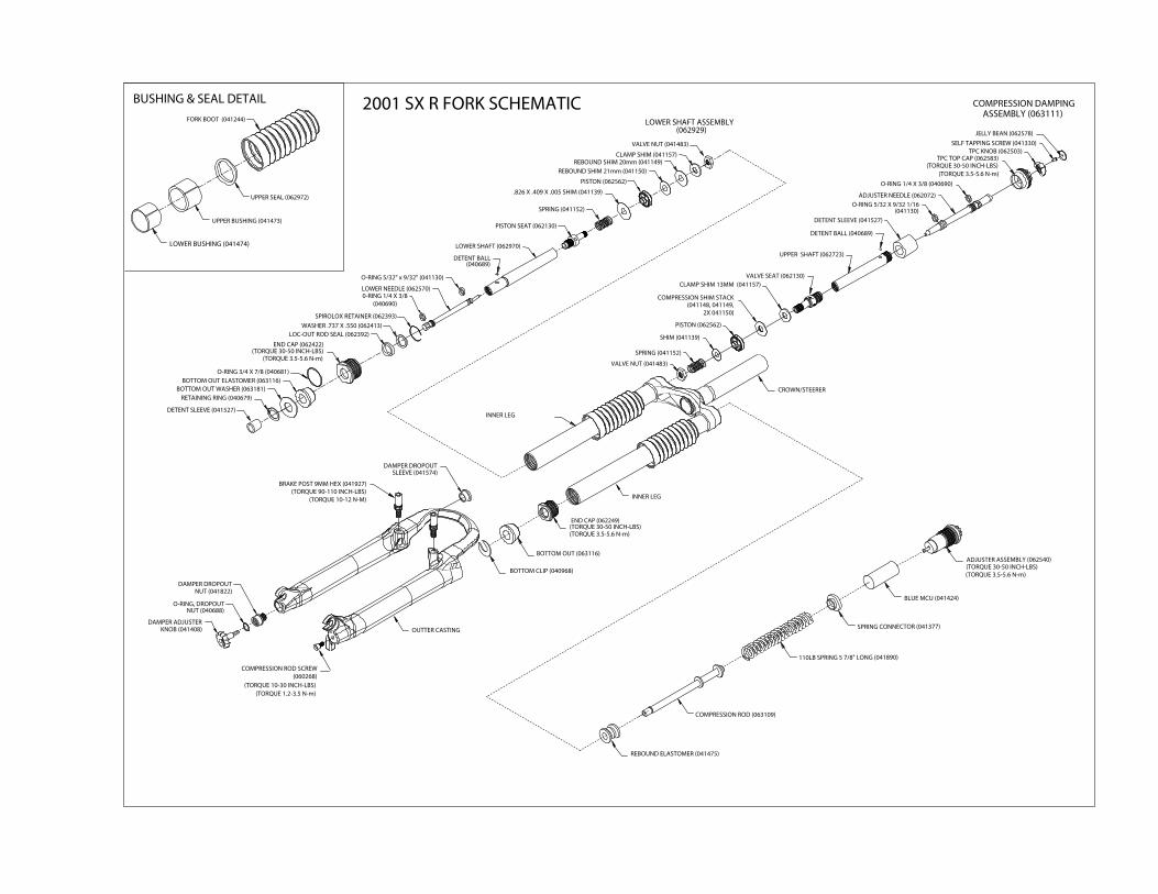
2001 SX R FORK SCHEMATIC
UPPER BUSHING (041473)
BUSHING & SEAL DETAIL
UPPER SEAL (062972)
LOWER BUSHING (041474)
FORK BOOT (041244)
CROWN/STEERER
DETENT BALL(040689)
DETENT SLEEVE (041527)
RETAINING RING (040679)
BOTTOM CLIP (040968)
DAMPER DROPOUT
DAMPER ADJUSTER
O-RING, DROPOUT
(TORQUE 1.2-3.5 N-m)(TORQUE 10-30 INCH-LBS)
COMPRESSION ROD SCREW(060268)
0-RING 1/4 X 3/8(040690)
SLEEVE (041574)DAMPER DROPOUT
COMPRESSION ROD (063109)
110LB SPRING 5 7/8" LONG (041890)
REBOUND ELASTOMER (041475)
BLUE MCU (041424)
ADJUSTER ASSEMBLY (062540)
INNER LEG
BOTTOM OUT (063116)
SPRING CONNECTOR (041377)
LOWER SHAFT ASSEMBLY
CLAMP SHIM (041157)
REBOUND SHIM 21mm (041150)
REBOUND SHIM 20mm (041149)
VALVE NUT (041483)
.826 X .409 X .005 SHIM (041139)
(062929)
LOWER SHAFT (062970)
SPRING (041152)
PISTON SEAT (062130)
PISTON (062562)
ASSEMBLY (063111)
DETENT SLEEVE (041527)
SELF TAPPING SCREW (041330)
JELLY BEAN (062578)
TPC TOP CAP (062583)
COMPRESSION DAMPING
VALVE NUT (041483)
SPRING (041152)
SHIM (041139)
VALVE SEAT (062130)
UPPER SHAFT (062723)
PISTON (062562)
CLAMP SHIM 13MM (041157)
COMPRESSION SHIM STACK(041148, 041149,
2X 041150)
DETENT BALL (040689)
ADJUSTER NEEDLE (062072)
O-RING 5/32 X 9/32 1/16
O-RING 1/4 X 3/8 (040690)
(041130)
O-RING 3/4 X 7/8 (040681)
END CAP (062422)
LOC-OUT ROD SEAL (062392)
SPIROLOX RETAINER (062393)
INNER LEG
END CAP (062249)
O-RING 5/32" x 9/32" (041130)
LOWER NEEDLE (062570)
KNOB (041408)
NUT (040688)
NUT (041822)
WASHER .737 X .550 (062413)
TPC KNOB (062503)
BRAKE POST 9MM HEX (041927)(TORQUE 90-110 INCH-LBS)
(TORQUE 10-12 N-M)
OUTTER CASTING
BOTTOM OUT ELASTOMER (063116)BOTTOM OUT WASHER (063181)
(TORQUE 30-50 INCH-LBS)(TORQUE 3.5-5.6 N-m)
(TORQUE 30-50 INCH-LBS)(TORQUE 3.5-5.6 N-m)
(TORQUE 30-50 INCH-LBS)(TORQUE 3.5-5.6 N-m)
(TORQUE 30-50 INCH-LBS)(TORQUE 3.5-5.6 N-m)

MAINTENANCEIMPORTANT: 2001 SX forks should not be used if any partsappear to be or are damaged. Contact your local dealeror Answer Products for replacement parts.
IMPORTANT: Use of fork boots is required to keep your2001 SX performing well and your warranty in effect.Use of this fork without boots will shorten the life of thefork, reduce the performance and void the warranty.
Your 2001 SX Fork requires periodic maintenance, clean-ing, and inspection. Moisture and contamination maybuild up inside the fork depending on the severity of rid-ing conditions. To maintain top performance it is recom-mended that the fork be periodically disassembled,cleaned, dried and re-greased.
IMPORTANT: When filling the fork with grease through the Microlube grease ports it is important tonote the grease is being forced between the upper and lower bushing (Figure 7). If the area is over-filled, the force of the grease may force the upper bushing and dust seal out.
IMPORTANT: Before every ride you should:1 Ensure that quick release skewers are properly adjusted and tight.2 Wipe the inner legs clean, lubricate and check entire fork for any obvious damage.3 Check headset adjustment.4 Ensure that the front brake cable is properly seated in the cable retainer & check brake
adjustment.
IMPORTANT: Maintaining the proper oil level in your TPC is very important. Not enough oil willallow foaming and reduce the performance. Too much oil will restrict travel and may causedamage to the system and an unsafe riding situation. Finish reading this entire section prior tomaking any changes to the oil level.
CHECKING OIL LEVEL FIGURE 8:To check the oil level, remove only the compression damp-ing assembly located in the top of the right leg. Leave theleft side compression stack (adjuster, MCU, spring assem-bly) in place to keep the fork fully extended. Use a tapemeasure or dip stick to determine the oil level. Oil levelshould be between 3.75 (95.2mm) and 4.75 (120.6mm)below the crown where the damping assembly screws in(see figure 8). The recommended level is 4.25”(107.9mm). It is recommended that you replace your oil atleast once a year, twice if it has been contaminated withdirt, mud, or other foreign substance. Use SAE 5WTMaxima fork oil or equivalent.
MINIMUM
MAXIMUM
RECOMMENDEDLEVEL

Removal of outer leg / arch assembly:1 Use a 4MM allen wrench to remove the M5 lower compression rod screw from the left leg
dropout. Pop out the damping adjuster knob from the right dropout, SXR. A small screwdrivermay be helpful. Use an 8MM Allen wrench to remove the dropout nut. Fully compress the forkto prevent the compression rod and damper shaft from turning while removing screws.
2 Pull outer leg assembly down to remove from the inner legs and crown.3 Remove fork boots.4 Bushing replacement will require the use of the bushing removal and installation tool available
from Answer Products. It is recommended that the bushings be left installed unless theyabsolutely need replacement.
Note: It is not recommended to remove the dust seal every time the fork is disassembled. The sealand bushings may be cleaned and re-greased in place.
GENERAL DISASSEMBLY NOTE: The Fork does not need to be removed from the bicycle for general disassembly-assembly orcleaning. It is also not necessary to disassemble the 2001 Manitou Forks for compression elastomerreplacement. Elastomer replacement is accomplished by removing the adjuster assembly per Figure 10.
Compression Stack & Compression Rod1 Press the bottom clip off the compression rod.2 Slide off the rebound elastomer from left leg compression rod.3 Unscrew and remove the adjuster assembly by hand.4 Turn fork upside down to remove the compression rod. If forks are installed on bicycle give the
rod a quick upward thrust and catch it as it pops up above the crown.
Lower Shaft Disassembly:Note: Lower Shaft disassembly is best done with the fork removed from the bicycle. Disassembly ofthe damping stack is not required unless you want to change or replace the shim stack.
1 Remove the left cap compression damping assembly from the top of the fork leg and pour theoil out of the top of the fork and discard appropriately. For complete disassembly continue.
2 Remove the plastic end cap and pull the lower shaft out of the inner leg.3 Remove the clear plastic detent sleeve and capture the 1/8 dia. Detent ball used on SX R only.4 SX R adjuster needle may be unscrewed from the shaft.5 For SX R use 5MM allen wrench to remove piston seat. Keep note of the exact order of the
shims and spacers.
Compression Damping Disassembly:1 The compression damping assembly is almost identical to the lower shaft assembly. 2 Unscrew the compression damping adjuster all the way until it stops. The knob and the needle
do not need to be removed. The shaft also does not need to be removed from the cap. Thethreads are bonded to prevent leaking.
3 Remove either the valve nut or the piston seat following the instructions above for the lowershaft assembly.

DAMPER INSPECTION1 Check the shaft for scratches, wear, or other obvious damage.2 Check the seal gland and end cap seal grooves for damage.4 Check shims for permanent bends or damage.5 Check all other parts for obvious damage, replace if necessary.6 Replace all seals that have been removed.
FORK INSPECTION1 Check the fork boots for obvious damage.2 Check the dust seal for tears, wear, or damage. Replace if needed.3 nspect the lower and upper bushing for damage to the Teflon coating. Replace using the bush-
ing removal and replacement kits if necessary.4 Check all MCU & springs for obvious damage. Replace if necessary.5 Check the preload adjuster and connectors. Replace if damaged.6 Check the outer leg/arch assembly for nicks or deep gouges on outside and inside. Replace if
damaged.7 Check the inner leg for deep gouges and other damage. Minor wear resulting in color change is
not detrimental to the gold anodized surface. Replace if wear is excessive or damaged.8 Check inner legs at the bottom of the crown for cracks or for flaking anodize. Replace crown
steer leg assembly if cracked or if gold anodize is beginning to flake.9 Check the underside of the crown for cracks. Replace if cracked.
RE-ASSEMBLELower Shaft
1 Install all o-rings and seals removed.2 Grease all seals lightly with seal grease.3 Apply small amount of blue Locktite to piston seat threads.4 Assemble shim stack and spacers in exact order that they were removed. For SX R hand tighten
piston seat. Be sure large blow off washer will slide over piston spacer and compress the smallspring. Clamp shaft in soft jaws or collet and line up slots in clamp ring with hole in pistonseat using 1/8 or smaller pin. Use a 5MM Allen wrench and tighten piston seat by turningAllen wrench and pin at same time. Torque 10 IN-LB (3.5 N-m) max.
5 SX R install lower needle gently into shaft, thread until it stops then back off one turn for ini-tial adjustment.
6 Slide shaft assembly through the plastic end cap, place detent ball in place and slide on 2ndSTG Elastomer.
7 Insert into left leg and thread in end cap. Torque 30 IN-LB (3.5N-m) max.8 Add approximately 90 CC of 5 WT Maxima or equivalent oil. Do not over fill. Check oil level,
see Figure 8.
Compression Damping Assembly 1 Reassemble compression damping stack following the instructions above for the lower shaft
assembly.2 Install compression damping assembly into the left leg. The oil level should cover the compres-
sion valve when the assembly is installed.

Compression Rod & Boots:1 Clean all parts thoroughly.2 Grease compression rod lightly. Be sure rebound Elastomer is installed onto compression rod.3 Drop compression rod down into inner legs. Shake inner leg to get rod through inner leg plug.4 Slide on black second stage, cup washer, and orange 3rd stage Elastomer.5 Slide Boots onto inner leg.
Outer Leg Assembly:1 Slide Outer leg / Arch assembly onto inner legs and fully compress.2 Install and torque 5MM compression rod screw and dropout nut to10-30 inch-lb. (1.1-3.5 N-m).
Over torquing the dropout nut may damage the damper shaft.3 Pop in damper adjuster knob. O-ring holds knob in place(SXR).4 Slide skirt of fork boots onto the outer leg groove. Be sure the lip snaps into the groove.5 Clean adjuster cap threads thoroughly. Clean threads on inside of inner leg.6 Assemble MCU’s, springs, and connectors with thick grease.7 In stall adjuster assembly into inner leg just hand tight.
INNER FORK LEGS & CROWNThe inner fork legs and steer tube are press fit into the crown and may never be removed.Removing them will make the fork unsafe to use. If you see any slippage contact Answer TechnicalStaff immediately (800) 670-7446.
ADJUSTING RIDE QUALITIES 2001 SX TPC forks offer a wide adjustment range to suit individual riding preference and riderweight by simply changing the MicroCellular Urethane (MCU’s). Fine tune adjustments can be madeusing the preload adjusters located on top of the fork crown. Softer blue and harder yellow MCU’sare available from your Dealer.NOTE: Since 2001 model forks use a compression stack in the left leg only, MCU’s and Springs usedin previous Manitou forks are NOT interchangeable with later versions of SX model Forks.
Compression Spring Fine Tuning:Fine tuning adjustments to the spring rate are made by rotating the adjuster knobs located on topof the crown. Note the 2001 SX 100, SX, and SX R uses compression spring systems in the left legonly. Only the left knob on top of the crown adjusts preload. Rotating the knob clockwise will firmthe ride, adding preload to the compression stack. Rotating the knob counter clockwise will softenthe ride. Four full revolutions will take the adjuster from full soft to the extreme firm setting.
Compression Damping Fine Tuning:To adjust the SX R simply rotate the compression damping knob located on top of the right leg andcrown. Rotating the knob clockwise will increase the damping, rotating the knob counter clockwisewill reduce the damping. Excessive damping will give you a harsh ride over sharp bumps like rockysections, but will feel good in large hits like G-outs. Insufficient compression damping will bottomout in the large hit G-outs and bob a little while climbing but feel plush on the sharp hits. A cor-rectly adjusted fork will perform good in all conditions. The SX 100 and SX uses TPC Sport for com-pression damping and is not adjustable.

Rebound Damping Fine Tuning:To adjust the SX R simply rotate the rebound damping knob located on bottom of the right leg.Rotating the knob clockwise will increase the damping, rotating the knob counter clockwise willreduce the damping. Excessive rebound damping will give you a harsh ride over repetitive bumps(like braking bumps) because the fork will pack up. Insufficient rebound damping will make the forkover active, top out and slap back when landing from a jump. We suggest that you try adjustingyour fork on the very active side, minimum rebound. Then try it over a variety of terrain and tunein more rebound from there. The SX 100 and SX uses TPC Sport for Rebound damping and is notadjustable
Lok-Out System Kit P/N 85-8989 Lok-Outs are available for all SX models. By turning the knob 1/4 turn CCW, exposing the greensticker; the front fork will have regular TPC suspension. By turning the knob 1/4 turn CW, exposingthe red sticker; the fork will be locked out. A safety blow off valve will open under extreme condi-tions to allow some movement. To adjust the compression damping when not using the Lok-Out.Remove the compression damping assembly from the top of the right leg. Adjust the setscrew,located in the valve seat, in to increase the damping and out to reduce the compression damping.Try adjusting one 1/2 turn at a time.
For additional tuning tips we recommend that you obtain a copy of the MRD tuningManual P/N 85-3485 and check out the MRD Race Tuning kits available at your dealer.

TROUBLE SHOOTING
Fork seems to top out or has a slight clunking feel when front wheel comes off the ground:Excessive preload or insufficient rebound damping will result in a top out . Select MCU’s that bet-ter fit your weight and riding style, having the preload adjuster set mid to low range, and increasethe rebound damping to eliminate top out.
The fork feels less active and is not getting the travel it used to when it was new:Chances are that the fork is developing stiction. Cleaning and applying light oil to the stanchionswill help.
Outer legs feel loose on inner legs and bushings, a knock or rock can be felt when pushed from side to side:A very small knock is normal with the new harder bushings. If the knock is excessive or you can feelthe fork rocking then the bushings should be removed and replaced. To do this you must have theAnswer Products Bushing Removal and Replacement Tool Kit.
A small amount of oil seems to be leaking from top of the left leg at the adjuster cap:If the 2001 SX us store upside down for a period of time a small amount of oil may leak through theadjuster cap / knob assembly. The cap area is not subjected to damping pressure. A small leak inthat area will not affect the performance of the fork or cause any type of damage. We recommendthat you store your Manitou left side up. If this condition causes you some problems please contactyour Answer Products dealer or call our warranty tech department for prompt service.
CYCLE COMPUTER INSTALLATION INSTRUCTIONS:Follow the instructions in your owners manual with the following exceptions:
WARNING: DO NOT DRILL A HOLE IN THE DROPOUT. THIS MAY WEAKEN THE DROPOUT, WILL VOIDTHE WARRANTY, AND MAY CAUSE AN UNSAFE CONDITION WITH RISK OF INJURY. DO NOT USE THETEMPLATE PROVIDED IN THE 95 OR 96 SERVICE MANUAL.
28209 AVENUE STANFORD • VALENCIA, CA 91355(661) 257-4411 • www.answerproducts.com
2001 SX SERVICE MANUALP/N 85-3692