manipulation of speech sounds - … bound... · philips tech. rev.40,no. 5 manipulation of speech...
TRANSCRIPT

134 Philips tech. Rev.40, 134-145, 1982, No. 5
Manipulation of speech sounds
J. 't Hart, S. G. Nooteboom, L. L. M. Vogten and L. ~.Willems
With the rapid development of microelectronics it is now possible to buy machines that talk.The speech capabilities of such machines are in general still very limited, but it is reasonable toexpect that 'synthetic speech' will come into much wider use within the next few years, e.g. inautomatic telephone information services, home computers or reading machines for the blind.The development of good synthetic speech will depend on the manipulation of speech soundsby electronic methods. It is therefore necessary first of all to find out which of the many andvariedproperties of a sound wave are essential to the perception of speech. In the article belowthe authors discuss some aspects of their research in this field, and deal with some results thatshould make it possible to produce natural-sounding synthetic speech.
Introduction
Speech is the simplest - and often the best - meansfor human communication. For solving business andtechnical problems it is often a much more effectivemeans of communication than writing or using a key-board and display. And the telephone now offers oralcommunication over virtually any distance.Since speech is such a good means of human corn-
munication, and since there is an increasing need forinformation exchange between man and machine, it isonly natural to ask whether speech might not also be asuitable medium for such man-machine communica-tion. The rapid development of microelectronics hasnow made this a real possibility. To answer thequestion it is necessary to investigate the physical char-acteristics of speechsounds, the possibilities of controlof these characteristics, and their relation to the per-ception of speech. Research along these lines is cur-rently taking place in many centres around the world.It also constitutes a major part of the. programmeof the Instituut voor Perceptie Onderzoek (IPO, TheInstitute for Perception Research) in Eindhoven.Speech research at the Institute is carried out with
the aid of a system (essentially a computer program)called SPARX, standing for SPeech Analysis and Re-synthesis eXperiments. This system, using a computerand peripherals for recording and reproducing sound,is capable of analysing natural speech sounds intothirteen parameters that change relatively slowly, i.e.no faster than the speed at which the pharynx andmouth cavity change shape. From these parameters
J. 't Hart, Prof. Dr S. G. Nooteboom, Ir L. L. M. Vogten andIr L. F. Wil/ems are with the Institute for Perception Research,Eindhoven.
the speech sounds can then be resynthesized. Theparameters represent physical quantities that aredirectly responsible for distinct elements of speechperception, such as pitch, loudness and the variousspeech sounds. The coding into thirteen slowly varyingparameters first of all allows the memory capacityrequired for storing the speech sounds to be reducedvery substantially. Secondly, it makes the speechsounds capable of manipulation, since the parameterscan be selectively processed before resynthesis, so thatcharacteristics such as intonation, i.e. the rise and fallin the pitch of the voice in speech, can be alteredwithout affecting the other characteristics. This abilityto manipulate speech sounds is of great importance inspeech-perception research and is particularly im-portant in the development of 'speaking machines'.Their counterpart, the 'listening machine' (automaticspeech recognition) lies outside the province of thisarticle.
Any machine that plays back tape may be regardedas a speaking machine. Familiar examples are tele-phone-answering devices and recorded time andweather information by telephone. In this article,however, we think of a 'speaking machine' as equip-ment that is much more versatile, which can composeits own answers from a vocabulary of words spokeninto it. Possible applications of such machines includereading aids for the blind, spoken instructions on howto use equipment, complex telephone systems thatprovide information automatically, and computersthat give a spoken output. The 'vocabulary' can alsobe thought of as built up from smaller spoken-in unitsthan words, e.g. syllables or phonemes.

Philips tech. Rev. 40, No. 5 MANIPULATION OF SPEECH SOUNDS 135
A primary aim in the development of speaking ma-chines is maximum economy in the storage of speechsignals. With a system like SPARX a speech signal of120 kbit per second is reduced via the thirteen param-eters to 16 kbit/s. It is also possible, however, at theexpense of the quality of the reproduced speech, tomáke do with fewer bits per second, by coarsening theparameter descriptions. The effect of such coarseningon the quality of speech reproduetion can be studiedwith SPARX.
In the second place the aim is to generate fluent andreadily intelligible speech utterances with the smallunits of the vocabulary, If the machine reproduces theright words in the right sequence but does nothingmore, the result is useless, since in natural speech thesound of a word depends closelyon its context. Toobtain fluent, intelligible speech the physical charac-teristics of each word must be matched to its context.This is a point where there is a particular need forresearch on speech perception and for the possibilityof manipulating speech sounds.The present article deals with research of this nature
with the SPARX system. In the first section we recapi-tulate the physical structure of natural speech, show-ing how it comes about and presenting a generallyaccepted model of speech production, which is also atthe base of SPARX. Next we deal with the systemitself, discussing some of the possibilities it offers for'playing with speech sounds'. Finally we discuss therules for generating sentence intonation, as an exampleof what is needed to synthesize speech utterances thatare reasonably intelligible.
Natural speech
Fig. 1shows a cross-section of the organs of speech.The physical principle of speech production is simple.There is a variable sound source and there is a variableacoustic filter that alters the sound from the source.For the vowels and the voiced consonants (e.g.
m, n, 1, r, b, d) the source sound is produced by vibra-tion of the vocal cords (2), which transmit air-pres-sure pulses from the trachea (1) at a particular fre-quency (the 'source frequency'). The source frequencydetermines the perceived pitch of the sound. A speakerregulates the source frequency, and hence the pitch ofhis speech, by varying the tension in his vocal cords.The average pitch varies from one speaker to another,and is generally higher for women and children thanfor men. The energy content of the pressure pulses,and hence the loudness, is determined by the pressuredrop across the glottis and the tension in the vocalcords. The sound volume varies very considerably:speech has a wide dynamic range (fig. 2).
The acoustic filter for the voiced sounds consists ofthe mouth cavity and the pharynx, and when the softpalate (4) does not shut offthe nasal cavity - e.g. forthe utterance of the nasal consonants m and n - it alsoincludes the nasal cavity. While speaking the speakercontinuously changes the shape of the pharynx andmouth cavity by movements of the tongue, the lowerjaw and the lips, so that the filter action and hence thephysical structure of speech sounds are continuallychanging. This is the main cause of the differencesbetween the individual vowels and consonants.For the unvoiced fricatives f, sand sh the source
sound is noise produced by turbulence of the airstream from the lungs in a -narrowing of the mouthcavity. For f this narrowing takes place between lowerlip and upper teeth, for s between the tip of the tongueand the teeth-ridge and for sh between the tongue andthe hard palate. The sounds of the voiced fricatives vand z have two sources: vibrations of the vocal cordsand air turbulences. For the unvoiced plosives p, tand k the mechanism is again somewhat different. Toproduce these sounds the passage of air through themouth cavity is stopped for a short time (about 50 to
Fig. 1. Cross-section of the organs of speech. 1 Trachea. 2 Vocalcords. 3 Nasal cavity. 4 Soft palate. 5 Tongue. 6 Mouth cavity.7Pharynx. .
allerl go there I we nis I' 'lIgh ti 0 bed
Fig. 2. Recording of the sound wave of the spoken sentence: 'AfterI got here, I went straight to bed'. The diagram gives the outputvoltage from the microphone (vertical axis) as a function of time(horizontal axis).

136 J. 't HART et al. Philips tech. Rev. 40, No. 5
150ms), and when the air pressure built up during thistime is suddenly released by opening the closure, ashort burst of sound is produced. The closure for ptakes place between the lips, for t between the tip ofthe tongue and the teeth-ridge and for k between theback of the tongue and the soft palate. For the voicedplosives b, d and g there is again a sudden opening ofa closure of the mouth cavity. These differ from theunvoiced plosives, however, in that the vocal cordsvibrate during the closure.For these fricative and plosive sounds the acoustic
filter is confined to the space between the narrowingthat produces the turbulences and the mouth opening.While the acoustic filter for g, for example, is formedby a large part of the mouth cavity, only a small partis used for producing s, while the source sound of fleaves the mouth practically unfiltered.
The source-filter theory of speechproduction
A generally accepted theory of speech production isG. Fant's 'source-filter theory' [11; seefig. 3a. In thismodel the sound originating from the source U as aseries of pulses, or as acoustic noise, passes throughtwo filters, consisting of the filter 0 formed by thepharynx, the mouth cavity and the nasal cavity, andthe filter R that represents the sound radiation at themouth opening. An essential feature of voiced soundis that the spectrum contains a large number of over-tones in addition to the fundamental tone (of fre-quency Fo); it is only through these overtones that thefilter 0 can produce such a marked effect. In the spec-trum of a normal voiced source the amplitude of theovertones decreases by about 12dB per octave. If thesource sound is acoustic noise, it is usually assumedthat its spectrum is practically flat ('white noise').The amplitude spectrum SU) of a steady-state
speech signal is now equal to the spectrum UU) ofthe source, multiplied by the transfer functions 0(/)and R(f) of the filters 0 and R:
SU) = U(f)· OU)· R (f). (1)
The transfer function R(f) represents the increasingdirectivity of the mouth opening to sound as the fre-quency increases and is equivalent to an increase ofthe on-axis sound radiation by 6 dB per octave.The transfer function OU) mainly determines the
'nature' of the speech sound. The mouth cavity to-gether with the pharynx may be regarded as a some-what irregularly shaped tube, which is almost closedat one end and open at the other. Such a tube has anumber of resonant frequencies that correspond topeaks, known as formants, in the transfer function0(/) (fig. 3b). Each formant is characterized by acentre frequency and a bandwidth. For the perception
of speech no more than five formants are generallyrequired, in the frequency range from 100 Hz to5 kHz. In order of increasing frequency they are de-noted byF, to F5. The intrinsic feature of vowels thatdistinguishes them from each other appears to dependprimarily on the first three formants. The formants F4and F5 do not essentially contribute to the recogniz-ability of speech sounds, but they do largely deter-
. mine the naturalness of the speech and the recogniz- .ability of the speaker.
In speech research as carried out with systems likeSPARX a simpler model is used, the 'synthesismodel' [21, as illustrated in fig. 4. It contains only onefilter 0, which combines the function of the filter 0 infig. 3a with that of R (6 dB increase per octave), andalso includes the 12dB decrease per octave of thevoiced source. The voiced source V therefore has a'fiat' spectrum here, consisting of a seriesof frequency
sit)
II
spectrum: Uit)
II
sin-o« )Off)R(f)
o 3 4-f
5kHz2
Fig. 3. a) Block diagram of G. Fant's source-filter model (1) for thespeech organs. The source sound u(t) from the source U (lungs andvocal cords) passes through the filter 0 (pharynx and mouth cavity)and the filter R (mouth opening) to become the speech sound s(t).The signals in the 'frequency domain' are indicated beneath thediagram. b) Transfer function 0(/) of the filter 0 for a particularshape of the pharynx-mouth channel; the peaks are called for-mants.
Fig. 4. The synthesis model. The filter 0 contains the functions ofo and R from fig. 3 together with the spectral structure of thesource (decrease of 12 dB per octave). The spectrum of the sourceis therefore 'flat' here: it is either a series of equidistant frequencycomponents of equal amplitude (V, voiced) or white noise (UV, un-voiced). The amplitude (g) of the sound is controlled by a variableamplifier between source and filter.

Philips tech. Rev. 40, No. 5 MANIPULATION OF SPEECH SOUNDS 137
u(t) U(f)
Q t c:::> t Q
07/FêJ -t o Fa 2Fa ... -f
.0t
S(t),
S(f) gO(f)Q t ~ t £
-t -fFig. 5. Signals and spectra in the synthesis model with voiced source. a) The source signal u(t), aseries of delta pulses with period IIFo. b) The spectrum U(f) of u(t), a series of components ofequal amplitude at a spacing Fo (fundamental with overtones). c) The spectrum S(f) of thespeech signal, which is the product of U(f), the amplitude gain g and the transfer function O(f)of the filter 0 in fig. 4. d) The resulting speech signal set).
components of equal amplitude at the frequencies Fs,2Fo, 3Fo and so on (fig. 5b). The correspondingsource signal consists of a series of delta pulses with aperiod of l/Fo (fig. 50). The unvoiced source UV is.again white noise. The spectrum SU) of the 'syn- .thesized' speech signal s(t) (see fig. 5c) is given by:
S U) = UU) . O(f) .
The envelope of this spectrum is not flat, and con-sequently the discrete pulses of fig. 50 are spread outin time (fig. 5d). The level of the speech signal can beadjusted by an amplifier between source and filter.
A FTER I GOT HERE
."'--..._ .~ ...:---.... '. 0
o 0.5 1.0 1.5-t
2.05
Fig. 6. Analysis of the speech utterance: 'After I got here, I wentstraight to bed' into the thirteen parameters, as functions of time.Logarithmic scales are used for the amplitude g and the source fre-quency Fo. For V/UV, voiced (V) is indicated by white, and un-,voiced (UV) by black. In the lower part, the formant frequenciesand bandwidths are marked every ID ms by five vertical bars. Thecentres of the bars represent Fl to Fs, the lengths give the qualityfactors Ql to Qs; the bandwidths are derived from these by the rela-tion B = FI Q. A long bar thus corresponds to a higher peak in thespectrum. The parameters are stored at a rate of 16 kbit/s.
(2)
In this model speech is described by the followingparameters: the binary parameter (V/UV) that deter-mines whether the source is voiced or unvoiced; thesource frequency Fo - for the case of a voiced source:the amplitude g; and the frequencies FI to F5 and thebandwidths BI to B5 of the formants that characterizeO. Anticipating the operation of SPARX, jig. 6 givesan example of a speech utterance analysed into thesethirteen parameters. Since these parameters representdistinct elements of the speech perception, they can beused as the starting points for reproducing and mani-pulating speech sounds. Neither this model nor
SPARX take account of the possibility that the sourcesound may simultaneously be periodic and noisy, likethe sounds 'v' and 'z'.
The SPARX system
Analysis of a natural speech signal s(t) (jig. 70) intothe thirteen parameters is really a matter of resolvingthe spectrum SU) of the signal (fig. 7b) into the twofactors of the model (fig. 7c,d): a relatively smoothtransfer function OU) of the filter 0 and the spec-trum of the source UU), which is a either a series ofequidistant frequency components of equal amplitudeor a white-noise spectrum. The analysis, and also theresynthesis, are not carried out in the 'frequencydomain' (Fourier analysis and Fourier synthesis),however, but entirely in the 'time domain' (operationson pulse series); this is done with a digital computer.We shall now discuss this method.
[1) G. Fant, Acoustic theory of speech production, Mouton, TheHague 1970..
[2) Seé for example J. D. Markei and A. H. Gray Jr., Linear pre-diction of speech, Springer, Berlin·1976.

138 J. 't HART et al. Philips tech. Rev. 40, No. 5
In the analysis the analog speech signal first has tobe digitized. It is therefore sampled at a frequency (inSPARX) of 10 kHz, i.e. at a sampling rate that makesproper allowance for frequencies in the spectrum upto nearly 5 kHz (Nyquist's theorem [31). Each sampleis then quantized to an integer value between -2048and +2047 (12 bits). One second of speech has thusnow been coded into 10000 X 12 bits, i.e. into 120 kbit.For the computer calculations we can now treat thesignals as time series of signal values (samples).
The filter and source characteristics are extractedfrom the speech signal independently of each other(fig. 8). We shall first consider the extraction of thefilter characteristics ('formant extraction'). This isdone in an analysis window of 250 samples (25 ms ofspeech), which shifts 100 samples (10 ms) at a time.The overlap between the successive windows is thus15 ms. The window is made large enough for it toalways contain more than one period of the sourcesound, yet kept small enough not to smooth out toomuch of the variation of the speech parameters with
s(t)Q t
0 10 20ms-t
S(f)
Q t20dB!
0 2 3 4 5kHz-f
Off)
ç_ t
-f
U(f)
t-f
Fig. 7. The analysis problem 'in the frequency domain' is to analysethe spectrum (b) of a natural (steady-state) speech signal (a) intothe factors of the synthesis model (c,d). The vertical scale is linearin (a) and logarithmic in (b) and (c). The analysis is in fact per-formed with a digital computer in the time domain.
sourceextraction
formantand
amplitudeextraction
Fig. 8. Diagram of the analysis. The extraction of the source char-acteristics (V/UV, Fo) and the extraction of the formants (FI, ... ,B5) and the amplitude (g) from the time sequence of speech samplesSn are carried out 'in parallel', independently of each other.
time. Before the analysis of the signal segment in awindow, it is multiplied by a 'Hamming window' [31
to avoid adverse transient effects due fo the abruptstart and finish. The changes in the physical character-istics of the speech sounds can readily be followedwith the analysis period of 10 ms of speech .'
The formant extraction - without knowledge ofthe source - is performed by linear prediction of thespeech signal. This is done using the model of thefilter 0 in fig. 9. The filter action is obtained by feed-back of the output signal Sn to the input via the 'pre-dictor' P (a transversal filter). In fig. 9 the indicationZ-l represents the operator that delays the signal byone sampling period. The signal Sn that appears at theoutput of P is therefore a linear combination of Sn-I,
Sn-2, ... , Sn-lO:
10
Sn = L aj Sn-joj=l
(3)
For the output signal in fig. 9 we now have:
Sn = gUn + Sn. (4)
This linear relation enables us to predict an outputsignal value from the instantaneous input value andthe ten preceding output values; hence the name'linear prediction'. Now Un is only seldom =1= 0 (thesampling frequency is very much higher than thesource frequency), so that 'nearly all' speech samplesare predictable just from the ten preceding samples [41.
This feature is utilized for making the 'best possible'determination ofthe coefficients al, ... , alO of P, with-out knowing anything about the source. The methodof least squares is used to calculate the values of al toalO that give the best match of Sn to the actual signalvalue Sn (see fig. 10), for all sample predictions Sn inthe window. Since Sn is the first prediction, we lookfor the values for which the expression
250
E = L (Sn - Sn)2 (5)n=ll
has a minimum.

Philips tech. Rev. 40, No. 5 MANIPULATION OF SPEECH SOUNDS 139
I---------------~gUn I 1 Sn
1+ + II II II Sn II II II + II P II· 0 IL ~
Fig. 9. Representation of the filter 0 as a 10th-order digital filter.The filtering action is produced by feedback of the output signal Snto the input via the 'predictor' P. The predietor delays the signal inten steps, multiplies it after each step by a coefficient (aj), and adds
10the results. Expressed mathematically P(z) = L aJz-J, where z-j
J=lis the operator that delays the signal by j sampling periods. At everyinstant the filter 0 is thus characterized by the ten coefficientsal, ... , 010.
+
+
Fig. 10. Determination of the coefficients of the predietor P foreach analysis window of 25 ms from natural speech. The (sampled)speech signal Sn is applied to the predietor and the signal Sn pre-dicted by P is subtracted from it. The desired values of the coeffi-cients are the values for which (sn - Sn)2, summed over the entireanalysis window, has a minimum.
The values found for al to alO are then convertedinto formant' frequencies and formant bandwidths.The conversion is based on the model infig. 11 for thefilter 0, which is equivalent to five resonators in cas-cade, each characterized by a frequency and a band-width. This conversion completes the formant ex-traction.
The procedure adopted also provides a good meas-ure for the amplitude g of the speech signal: thesquare root of the minimum Emin found for E (seeeq. 5). In resynthesis this gives good results. This is tobe expected, since eq. (4) indicates that the mean of(Sn - &11)2 taken over a segment can never be zero, butmust be equal to the mean of (guni.
The method outlined here for determining the coefficients al toalO of the filter 0 is called 'Linear Predictive Coding' (LPC) [4); it isalso referred to as 'Wiener Filtering' [6) or 'Inverse Filtering' [7).
The method is heuristic: it does not follow strictly logically fromthe problem posed, but can ultimately be justified because it leadsto manageable equations for àl to alO and, as appears from theresynthesis, it gives good analysis results [2).
The model in fig. 9 has its limitations. It is an 'all-pole filter',which implies that it can represent 'resonances' but not 'antireso-nances'. Since the nasal cavity operates as an 'antiresonator' duringnasal sounds, the model does not do full justice to such sounds.
Sn
For the extraction of the source characteristics (seefig. 8) the first procedure is to count the number ofzero crossings of the speech signal in unit time. If thisnumber exceeds a critical threshold, the source is clas-sified as unvoiced (UV), in the other case as voiced(V). This extremely simple procedure serves well inpractice.
For determining the source frequency of voicedsound the analysis window is increased to 40 ms, toensure that at least two periods fall within the windoweven at the lowest source frequencies; this is necessaryfor the recognition of the periodic structure. Thedetermination is made by using a modification of theautocorrelation method, which is based on the strongcorrelation between samples spaced by one period (ifthere are any periods at all) [81. Fig. 12 gives the auto-
N-k
correlation function R(k) (= I SnSn+k) as an example11=1
for a speech segment of 40 ms (N = 400). The timeshift T of the largest peak away from the origin givesthe pitch period.
Fig. 11. Representation of the filter 0 as five second-order digitalfilters in cascade. If the coefficients PI, ... , q5 satisfy the relation
10 5I + L ai z:' = 1t (I + PkZ-l + qkz-2)
1=1 k=l
the filter is equivalent to the 10th-order filter in fig. 9. The a's areconverted into the p's and q's using the Bairstow routine [5). Eachof the second-order filters is equivalent to a resonator, and the filtero is thus equivalent to five resonators in cascade. The resonantfrequency F and the bandwidth B of a resonator are connected withthe coefficients pand q by the relations
P = - 2 exp (-nBT) cos 2nFT,q = exp (- 2nBT),
where T is the sampling period.
[3) See for example L. R. Rabiner and R.W. Schafer, Digitalprocessing of speech signals, Prentice-Hall, Englewood Cliffs1978.The Nyquist theorem is also discussed in: F. W. de Vrijer,Philips tech. Rev. 36, 305, 1976, on page 343.
[4) See for example B. S. Atal and S. L. Hanauer, J. Acoust. Soc.Amer. 50, 637, 1971.
[5) See for example C.-E. Fröberg, Introduetion to numericalanalysis, 2nd edition, Addison-Wesley, Reading, Mass., 1969.
[6) N. Levinson, J. Math. and Phys. 25, 261, 1947.[7) J. D. Markel, IEEE Trans. AU-20, 129, 1972.[8) L. R. Rabiner, IEEE Trans. ASSP-25, 24, 1977.

140 J. 't HART et al. Philips tech. Rev. 40, No. 5
Determining an autocorrelation function is very time-consuming,because of the many multiplications. For this reason SPARX doesnot use the autocorrelation function but a modification of it, inwhich Sn is not multiplied by the displaced sampling value Sn+k itselfbut by the sign of Sn+k. Only additions and subtractions are thenrequired.
To save more computer time, the search for the peak of the auto-correlation function in each analysis window is limited to a smallrange on the r-scale (see fig. 12) concentrated around the peakfound in the preceding correlation diagram. This method is basedon the knowledge that the source frequency in speech sound variesrather slowly. It guarantees a certain continuity in the measuredFo-value, even through the analysis windows in which the periodic-ity of the signal is not very clear, e.g. because of low intensity. Thedisadvantage of the method is that once a serious error has beenmade, for example an octave jump, the error remains. For the firstanalysis window of a series of 'voiced windows' the area on ther-scale must be made wide enough for it to include the possiblesource periods of the speaker.
-T
R(War ~W~ ~2a~ ~3~a~-----4~a~m~s
R(k)
t
- R(a)a.:------~1a::::-a------:::-2a~a:----~3;:-;a~a------:-4-:::-aa~-k
Fig. 12. The autocorrelation function R(k) of a speech segment40 ms long. This function gives the correlation between samplesseparated by k sampling periods (r seconds), wher.e r = kT, and Tisthe sampling period. If the signal has periodicity, the periodsappear as maxima in the autocorrelation diagram.
C
16kb/s
o'!..0.!l~i~ _resynthésis
120kb/s FILTER SOURCE
~>-@] L-vIUV
............... 0" 0'0
f t· v-==:oIL.. ----(0,. o'o}
1-------11-- - F,. 85temporal
- -- - structureM
I
(L.kb/s)
(Ikb/si
Fig. 13. Block diagram of SPARX. The analysis takes place in the upper half, the resynthesis inthe lower half. A/D analog-to-digital conversion, D/A digital-to-analog conversion. M diskmemory; this is used at four places in the diagram: for storing the speech signal in digital formboth before the analysis and after the resynthesis, and for storing the parameters obtained fromthe analysis and as used for the resynthesis. A 'manipulation' can be made between both sets ofparameters (coarsening of the description or a change in the variation of some of the parameters).C computer, in which the actual analysis and resynthesis take place. The blocks in C onlyrepresent software, of course, and not hardware. The manipulation can be made either by theintervention of the experimenter or by means of a program in the computer. In the resynthesis theparameters al> ... , 010 or Pl> ... , q5 obtained in the formant extraction can be used instead ofFi, ... B5.
Fig. 13 gives a block diagram of the entireSPARX system. The upper part represents the anal-ysis of a speech signal, as described above. To sum-marize, the spoken analog signal is converted to120 kbitls, and stored in the disk memory M. Itis then available for analysis into the parameters
viUV, ... , B«. These are stored in M for each 10 msof speech.
The resynthesis (lower part in fig. 13) takes place asindicated in the diagram given in fig. 4, and essentially.amounts to a reversal of the analysis. The parametersfrom the memory are used to control a 'source' and a

Philips tech. Rev. 40, No. 5 MANIPULATION OF SPEECH SOUNDS 141
Fig. 14. Analysis data from the same speech utterance as in fig. 6 but with a reduced number ofbits for the parameters: a) 4 kbit/s, b) 1 kbit/s. So as to reduce the bit rate, the number of for-mants is limited to 4, and only the quality factor Q4 of the fourth formant can be varied; F4 isfixed. In (b) the parameters are only given for every 40 milliseconds; in between there is automaticlinear interpolation.
'filter' (not hardware, but software). They are up-dated after each 10 ms of speech; the output signal isagain stored in M, as samples at a rate of 120 kbit/s,and after conversion it can be made audible through aloudspeaker.
Speech research with SPARX
With SPARX the set of parameters obtained byanalysis can be modified before the resynthesis, andthe effect of the modification on the speech soundscan be studied. We shall consider here two kinds ofmodification: coarsening the parameters ('bit-ratereduction') and altering the behaviour of the param-eters ('playing with sound').
A FTER I GOT HERE I WENTSTRAIGH T TOBE 0------rf
- f-.: f----. f
-. - - .-
a
Bit-rate reduction
As we said in the introduction, it is very importantin various applications of speaking machines to beable to store speech utterances or speech signals aseconomically as possible.After analysis a speech signal in SPARX is stored at
a rate of 16 kbit/s (each second of speech contains100 analysis frames, each frame produces 13 param-eters, and each parameter is on average described bysome 12 bits). This is a substantial reduction com-pared with the original 120 kbit/s (see page 138). Indirect resynthesis the process does give some loss ofquality, but the result is highly intelligible and thesound quality is good.
To save memory space in the computer a coarserform of storage can be used. The result of such acoarsening can be monitored with SPARX. Thecoarsening takes place in two ways. In the first placethe model parameters are quantized more coarsely,and in the second place the number of analysis stepsper second is reduced.This reduction is sometimes permissible because the
changes in the speech sounds usually take place fairlyslowly. Rapid changes in speech effects, such as thesudden increase of energy in plosives (p, t, k, b, d) arenot therefore reproduced so well when the number ofanalysis steps is reduced.The permissible quantization is not the same for all
parameters. The human ear is fairly sensitive to
A FT ER I GOT HERE I WENTSTRAIGH T TOBE 0
j__I~ 4kHzr1~o$~es.-i5l~e.:! Gea~""'~:~>femt+ 31 __: ". . _....:\1"--$ssF ._ .: '._
.::~::;:< ::"'~'" . / - / ;.../-.." __.- )..:' 2v _.".. _ . .
.... ,..:.__.:,.- _.: "' .._.: .......__..r--.: _
--~~ 0o 0.5 1.0 1.5 2.05-t b
changes in the frequencies of the lowest three for-mants, but is much less sensitive to changes in the fre-quencies of the fourth and fifth formants. These cantherefore be quantized very roughly or everi .taken asfixed. Nor do the bandwidths of the formants have tobe very exactly preserved.If careful attention is paid to the quantization,
speech is still readily understandable after a reductionto 1 kbit/ s. Below this level the intelligibility of speechrapidly decreases. In practical applications 4 kbit/sseems to be a good compromise. Fig. 14 gives theparameters for the same speech utterance as in fig. 6,.but now described at a rate of 4 kbit/s and 1 kbit/s,respectively.

142 J. 't HART et al. Philips tech. Rev. 40, No. 5
Playing with speech sounds
SPARX allows the experimenter to 'play' with thevariations in pitch, in amplitude or in one or more ofthe other parameters, without affecting the others,and to study the effect of such changes on the speechsounds. In addition to the thirteen parameters there isa 'hidden' parameter, which has already been includedin fig. 13: the time structure. Fig. 15gives an examplein which both the pitch and the time structure aremanipulated, in such a way that the utterance not.only sounds different, but has changed its meaning.
THEau EE N SAID THE KNIGHTI 5 A M ON S TE R
a -t
and sounds reasonably natural. The chance of findingsuch rules is based on the possibility of replacing thecapricious variation of the parameters of naturalspeech by a strongly simplified, 'stylized' variation,with not too great a degradation of the intelligibilityand sound quality.
Rules of adaptation will have to be made for theduration, the sound volume, the source frequency andthe formant frequencies of the word sounds in thevocabulary. Our research on this topic at our Insti-tute, particularly on the source frequency (the pitch),
5000
.'-,.
400HzL200f
_ ~700- 'j50
"-_ .----- ....
7.5-t
o2.05
b
Fig. IS. a) Data from an analysis of the speech utterance: '''The Queen", said the Knight, "is amonster"'. b) The same data after the following manipulations: change of the pitch contour of'The Queen said'; lengthening of the sound 'ai' in 'said' by a factor of 2; shortening of 'TheQueen' by a factor of 0.8; insertion of a 200ms pause after 'said'. These manipulations changethe meaning to: 'The Queen said "The Knight is a monster"'.
The ability to manipulate speech sounds is essentialto the development of speaking machines. To makethis clear in the present context, we shall consider a'text-to-speech' system that converts text (presentedin digital form) into speech sound. The system recog-nizes the words of the text and calls the appropriatespeech sounds, coded in the thirteen parameters, fromits vocabulary [91. As we have seen (page 135) theword sounds called must then be matched to theirsound context in the speech utterances. Many workersin many countries are trying to find appropriate rulesfor this matching process. The rules must be simpleenough for them to be translated into algorithms forthe machine, and at the same time they must produceadaptations that lead to speech that is understandable
has resulted in a set of useful rules that we call an'intonation grammar'. Investigations into rules forthe other parameters are in full progress.
To conclude this article we shall discuss the intona-tion grammar we have devised for British English. Weshall consider only a very simplified version, since weare only concerned here with illustrating our researchon this subject. We have deduced this grammar froma large number of stylized pitch contours of natural
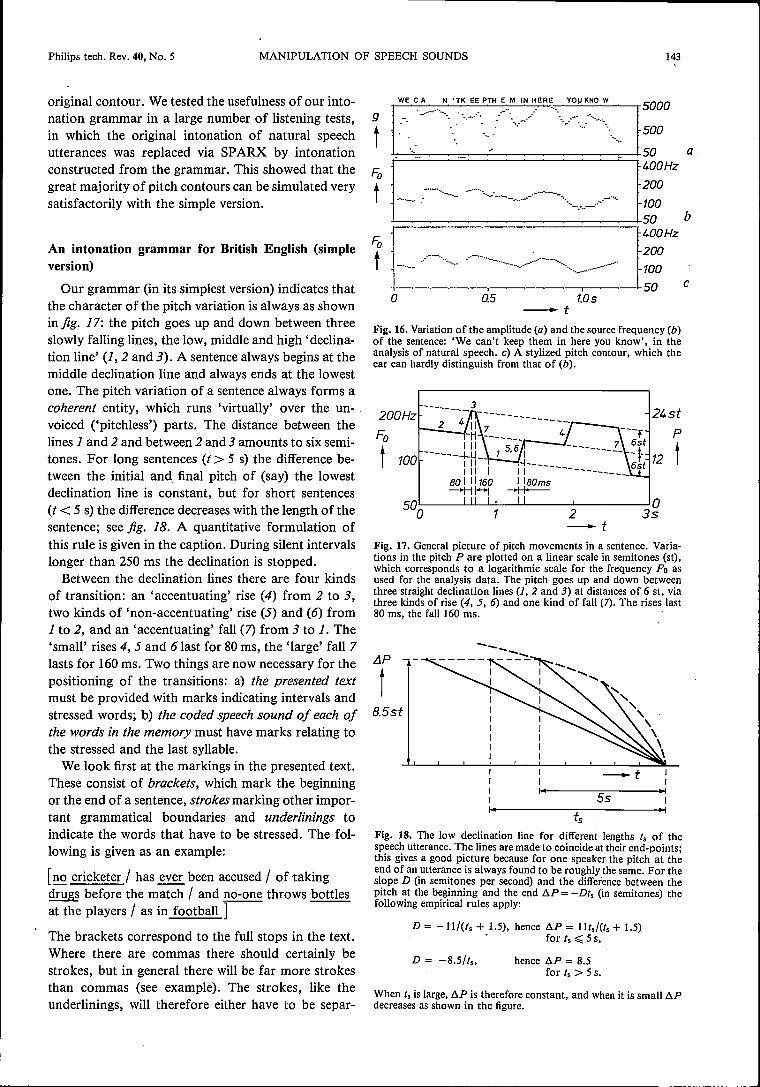
. speech. The stylization can be quite drastic withoutnoticeable degradation of the resultant speech. Fig. 16gives an example of a stylized pitch contour thattrained listeners found indistinguishable from the
[9] Systems of this kind already exist for American English; seefor example D. H. Klatt, IEEE Trans. ASSP-24, 391, 1976.
Philips tech. Rev. 40, No. 5 MANIPULATION OF SPEECH SOUNDS 143
original contour. We tested the usefulness of our into-nation grammar in a large number of listening tests,in which the original intonation of natural speechutterances was replaced via SPARX by intonationconstructed from the grammar. This showed that thegreat majority of pitch contours can be simulated verysatisfactorily with the simple version.
An intonation grammar for British English (simpleversion)
Our grammar (in its simplest version) indicates thatthe character of the pitch variation is always as shownin jig. 17: the pitch goes up and down between threeslowly falling lines, the low, middle and high 'declina-tion line' (1, 2 and 3). A sentence always begins at themiddle declination line and always ends at the lowestone. The pitch variation of a sentence always forms acoherent entity, which runs 'virtually' over the un-voiced ('pitchiess') parts. The distance between thelines 1 and 2 and between 2 and 3 amounts to six semi-tones. For long sentences (t> 5 s) the difference be-tween the initial and final pitch of (say) the lowestdeclination line is constant, but for short sentences(t< 5 s) the difference decreases with the length of thesentence; see jig. 18. A quantitative formulation ofthis rule is given in the caption. During silent intervalslonger than 250 ms the declination is stopped.
Between the declination lines there are four kindsof transition: an 'accentuating' rise (4) from 2 to 3,two kinds of 'non-accentuating' rise (5) and (6) from1 to 2, and an 'accentuating' fall (7) from 3 to 1. The'small' rises 4, 5 and 6last for 80 ms, the 'large' fall 7lasts for 160ms. Two things are now necessary for thepositioning of the transitions: a) the presented textmust be provided with marks indicating intervals andstressed words; b) the coded speech sound of each ofthe words in the memory must have marks relating tothe stressed and the last syllable.We look first at the markings in the presented text.
These consist of brackets, which mark the beginningor the end of a sentence, strokes marking other impor-tant grammatical boundaries and underlinings toindicate the words that have to be stressed. The fol-lowing is given as an example:
[no cricketer / has ever been accused / of takingdrugs before the match / and no-one throws bottlesat the players / as in football ]
The brackets correspond to the full stops in the text.Where there are commas there should certainly bestrokes, but in general there will be far more strokesthan commas (see example). The strokes, like theunderlinings, will therefore either have to be separ-
o QS 1.0s-t
Fig. 16. Variation of the amplitude (a) and the source frequency (b)of the sentence: 'We can't keep them in here you know', in theanalysis of natural speech. c) A stylized pitch contour, which theear can hardly distinguish from that of (b).
Fa
t----- 24st
P
t100
500~---W~~~~----~------~02 35-t
Fig. 17. General picture of pitch movements in a sentence. Varia-tions in the pitch P are plotted on a linear scale in semitones (st),which corresponds to a logarithmic scale for the frequency Fa asused for the analysis data. The pitch goes up and down betweenthree straight declination lines (l, 2 and 3) at distances of 6 st, viathree kinds of rise (4, 5, 6) and one kind of fall (7). The rises last80 ms, the fall 160 ms.
!JP
t ....."",\
\\\
8.5st
-t55
tsFig. 18. The low declination line for different lengths ts of thespeech utterance. The lines are made to coincide at their end-points;this gives a good picture because for one speaker the pitch at theend of an utterance is always found to be roughly the same. For theslope D (in semitones per second) and the difference between thepitch at the beginning and the end /lP = -Dts (in semitones) thefollowing empirical rules apply:
D = -Il/(Is + 1.5), hence /lP = IIts/(ts + 1.5)• for ts ~ 5 s,
D = -8.5/t .. hence /lP = 8.5for ts > 5 s.
When ts is large, /lP is therefore constant, and when it is small /lPdecreases as shown in the figure.

144 J. 't HART et al. Philips tech. Rev. 40, No. 5 .
ately marked by hand, or will have to be determinedby text-analytical rules. These are by no means simpleand we shall not consider them here. The brackets andstrokes divide the text into 'blocks'.The transitions in the sentence are distributed as
follows. At the strokes, and only there, there are tran-sitions 5 or 6. Each block therefore contains one rise4 and one fall 7 (see fig. 17). If there is one stressedword, both rise and fall occur in that word; if thereare two, then the 4 occurs in the first and the 7 in thesecond. Cases with more than two stressed words perblock are not considered here. We illustrate theserules in the following example; thin dashes representunstressed words and thick dashes represent stressedwords:
5/6[_i_ _ .Z: / 4,7
5/6/ 4,7 _]
To permit a decision as to where the rise 4 or the fall7 (or both) occurs in or near. a stressed word, thespeech sound of that word must be provided with a'flag' 1 in the memory, which marks the vowel onset ofthe syllable with the lexical stress. For the decision onthe choice between 5 and 6 and their precise location,the end of the last tonal part of the word sound mustalso be marked (1). Examples:
cricketer accused match
1 111(The speech sounds here are replaced for convenienceby the words in ordinary spelling.)
Where the 'parsing of the sentence' now requires afall 7, this always starts 30 ms after the flag I. If theprevious rise 4 occurs in the same word, it starts 80 msbefore this flag (and therefore ends there; fig. 19a); if,on the other hand, it occurs in a previous word, itstarts 30 ms before the flag 1 of that word (fig. 19b).
The difference between 5 and 6 is a difference be-tween the audibility or non-audibility of the rise be-fore the associated stroke. In the first case we havea rise 5; this ends at the flag 1 before the stroke(fig. 19c). In the other case we have a rise 6; this startsat that flag (fig. 19d). The rise 6 is therefore alwaysvirtual or partly virtual.
There still remains the choice between 5 and 6. Therise 6 is chosen if one or more of the following situ-ations occurs (seefig. 20):- The last syllable before the stroke has the lexicalstress (whether that word is stressed or not) or it onlyhas a 'short' tonal part (fig. 20a and b).- The first word after the boundary is stressed and itsfirst syllable has the lexical stress, or it is the word'and' or 'or' (fig. 20c and d).
If neither of these situations occurs, the choice fallson 5. To exemplify fig. 20b, the caption to fig. 20 givesa few words with a 'short' and a 'long' tonal part inthe last syllable.These rules enable the pitch contour to be estab-
lished. The result for the example is:
4 7 5 4,7 5 4,7no cricketer / has ever been accused / of taking drugs] ] 1] 1 ]
6 4,7 5 4,7before the match / and no-one / throws bottles at the
1 1 1 1r--,
5 4,7players / as in football
1 1
~The stroke after 'match' receives a 6 for two
reasons: the last tonal part before the stroke is short,and after the stroke comes 'and'. The four otherstrokes receive a 5: none of the situations in fig. 20occurs here. In the example only the word flags rele-vant to the sentence analysis are noted. The declina-
4. 7 4 7
1I
_Jf'II
I I !I I I
301 I I~I
I I
~
I
II II II II II I
301 I-+H-- I
I I
I 160ms
I I, I
""I I, 130
-+t-;+-- II I I ,l+ëOil~
......_5_/.UV V UV
l......Yi.....
_6_/UV V UV
I,_---.BD
l, ,..-'6,',I," I
_____.___J,' I, II It.-.lBOms
Fig.19. a, b) Location ofthe transitions 4 and 7relative to ], a) forone stressed word, b) for two stressed words in a block. c, d) Loca-tion of the rises 5 and 6 relative to the flag 1 at the last transition Vto UV before a block boundary; 5 is audible, 6 (at least partly) isinaudible (virtual).

Philips tech. Rev. 40, No. 5 MANIPULATION OF SPEECH SOUNDS 145
__fIZZJ)."" ...--I:Z:liJ )..,.""
~). ...,,'I I
-i-i).. ....I I
UVIVI---l, I--_., ,__'short '
......:..jIo/??4__ .".....Jand .................jor .
Q
Fig, 20, Cases where the rise 6 should be chosen at a boundary, Thehorizontallines represent words, the thick lines stressed words, anda block represents a syllable with lexical stress. a) Last syllablebefore the stroke has the lexical stress. b) Last syllable before thestroke has a 'short' tonal part. c) First word after the stroke isaccentuated and its first syllable has the lexical stress. d) First syl-lable after the stroke is 'and' or 'or'. Examples of words with a'short' or 'long' tonal part in the last syllable:
short: match, it, bat.long: cricketer, really, bad.
tion is not included in the contour. Since the speechsounds here are also replaced by the words in ordinaryspelling, the time structure is probably distorted.A contour of this type only gives changes in pitch;
the pitch itself still has to be established at one point.We have found that for a single speaker all the senten-ces end at approximately the same pitch (see fig. 18);the choice of that pitch establishes the pitch of theentire speech utterance. For a simulated male voice75 Hz is a suitable final value of the source frequency,and for a simulated female voice 150 Hz.
In this article we have confined ourselves to a simpleversion of an intonation grammar with seven pitchmovements. A refinement of our method enables us todistinguish at least 18 pitch movements for BritishEnglish [lOl. The simpler version discussed in thearticle represents the most common type of intonationpattern in British English speech, however, and there-fore seems to us to be very suitable for pitch regula-tion in synthetic speech.
(10) J. R. de Pijper, IPO Annual Progress Report IS, 54, 1980.
Summary. At the Institute for Perception Research (IPO) speechis studied with the aid of a system called 'SPARX' , for SPeechAnalysis and Resynthesis eXperiments. It is based on the com-monly accepted 'synthesis model' for speech production, consistingof a sound .source that produces a 'voiced' pulse series or 'un-voiced' noise both with a fiat spectral envelope, plus a variable filterthat brings about all spectral effects of the speech organs. In SPARXan incoming speech signal is digitized and then analysed - bymeans of linear predictive coding (LPC) and a modification of theautocorrelation method - into the thirteen parameters of themodel. These are the binary parameter that indicates whether thesource is voiced or unvoiced, the source frequency, the amplitude,and the five frequencies and bandwidths of the 'formants', whichcharacterize the filter. From these parameters the speech sound canbe resynthesized, and manipulated by operations on the param-eters. Examples discussed are coarsening of the parameters for thepurpose of storing speech signals more economically, and manipu-lation of the pitch and time structure in such a way as to alter themeaning of a speech utterance. Finally an intonation grammar isdiscussed that seems suitable for regulating the pitch of syntheticspeech. SPARX is used here for determining the extent to which thepitch variation can be 'stylized' without degrading the perception.

146 Philips tech. Rev. 40, No. 5
Scientific publicationsThese publications are contributed by staff of laboratories and plants that form part ofor cooperate with enterprises of the Philips group of companies, particularly by staff ofthe following research laboratories:
Philips Research Laboratories, Eindhoven, The Netherlands EPhilips Research Laboratories, Redhill, Surrey RHI 5HA, England RLaboratoires d'Electronique et de Physique Appliquée, 3 avenue Descartes,
94450 Limeil-Brévannes, France LPhilips GmbH Forschungslaboratorium Aachen, WeillhausstraBe, 51 Aachen,
Germany APhilips GmbH Forschungslaboratorium Hamburg, Vogt-Kölln-StraBe 30,.
2000 Hamburg 54, Germany HPhilips Research Laboratory Brussels, 2 avenue Van Becelaere, 1170 Brussels
(Boitsfort), Belgium .B ~Philips Laboratories, N.A.P.C., 345 Scarborough Road, Briarcliff Manor,
N.Y. 10510, U.S.A. N
H. A. Aigra & J. M. Robertson: Inhomogeneities inhorizontally dipped LPE (La,Ga):YIG films studied byspin wave resonance.J. appl. Phys. 50,4295-4301,1979 (No. 6). EP. M. Asbeck, D. A. Cammack, J. J. Daniele &V. Kle-banoff: Lateral mode behavior in narrow stripe lasers.IEEE J. QE-15, 727-733,1979 (No. 8). N
H. M. J. M. van Ass: Diffusion kinetics of some glasssystems used for the production of optical fibres.J. non-cryst. Solids 33, 325-334, 1979 (No. 3). ER. N. Bates & M. D. Coleman: Millimetre wave finlinebalanced mixers.Conf. Proc. 9th Eur. Microwave Conf., Brighton 1979,pp.721-725. R
M. Berth & C. Venger: L'implantation ionique dansGaAs pour transistors à effet de champ et circuits in-tégrés.Acta Electronica 23,23-35, 1980 (No. I). LM. Binet: Mesure rapide des profils de concentration etde mobilité des couches minces de GaAs.Acta Electronica 23, 53-61, 1980 (No. I). L
H. Bouma (Institute for Perception Research, Eindho-ven): Introduetion to section (Letter and word recog-nition'.Processing of visible language, Vol. 1, ed. P. A. Kolers,M. E. Wrolstad & H. Bouma, pp. 221-225; PlenumPress, New York 1979.
H. Bouma (Institute for Perception Research, Eindho-ven): Introduetion to section "Iechnological media forvisual presentation',Processing of visible language, Vol. 1, ed. P. A. Kolers,M. E. Wrolstad & H. Bouma, pp. 447-449; PlenumPress, New York 1979.
D. G. Bouwhuis (Institute ·for Perception Research,Eindhoven): Word knowledge and letter recognition asdeterminants of word recognition.Processing ofvisible language, Vol. 1, ed. P. A. Kolers,M. E. Wrolstad & H. Bouma, pp. 269-281; PlenumPress, New York 1979.
J. J. M. Braat & P. F. Greve: Aplanatic optical systemcontaining two aspheric surfaces.Appl. Optics 18,2187-2191, 1979 (No. 13). E
F. J. A. den Broeder & J. van der Borst: FesoB20-xSixglasses: A study of some physical properties as de-pending on metalloid content.J. appl. Phys. 50, 4279-4282,1979 (No. 6). E
J. J. van den Broek, H. Donkersloot, G. van Tendeloo*& J. van Landuyt* (* Rijksuniversitair Centrum Ant-werpen): Phase transformations in pure and carbon-doped Al45Mn55 alloys.Acta met all. 27, 1497-1504, 1979 (No. 9). E
E. Bruninx, A. van Eenbergen & A. Schouten: The de-termination of zinc, copper, lead and manganese inphosphate-containing matrices by coprecipitation oniron(III) hydroxide and x-ray fluorescence spectro-metry.Anal. chim. Acta 109,419-423, 1979 (No. 2). E
K. H. J. Buschow: Intermetallic compounds of rareearths and non-magnetic metals.Rep. Prog. Phys. 42,1373-1477,1979 (No. 8). E
K. H. J. Buschow, U. Goebel (T.H. Darmstadt) &E. Dormann (Univ. Bayreuth): Valence instabilities inCeSn3 and YbAla.Phys, Stat. sol. (b) 93, 607-615, 1979 (No. 2). E
J. P. Chané & J. Hallais: La croissance épitaxiale deGaAs pour transistors à effet de champ.Acta Electronica 23, 11-21, 1980 (No. I). L
T. A. C. M. Claasen & W. F. G. Mecklenbräûker: TheWigner distribution - a tool for time-frequency signalanalysis, Part 11: Discrete-time signals.Philips J. Res. 35,276-300, 1980 (No. 4/5). E
T. A. C. M. Claasen, W. F. G. Mecklenbräuker, J.B. H.Peek & N. van Hurck: Signal processing method forimproving the dynamic range of AID and DIA con-verters.Proc. 1979 Int. Symp, on Circuits and systems (ISCAS),Tokyo, pp. 193-196. E

,/
Philips tech. Rev. 40, No. 5 SCIENTIFIC PUBLICATIONS 147
T. E. G. Daenen: Cyclic reaction mechanism in theelectrodeposition of aluminium.Nature 280,378-380, 1979 (No. 5721).
Ph. Delsarte: A refined version of Khachian's algo-rithm.Philips J. Res. 35, 307-319,1980 (No. 4/5).
J. G. Dil & B. A. J. Jacobs: Apparent size ofreflectingpolygonal obstacles of the order of one wavelength.J. Opt. Soc. Amer. 69, ~50-960, 1979 (No. 7). E
P. Eckerlin & S. Garbe: Analysis of tungsten com-pounds in the wall region of halogen lamps.Philips J. Res. 35, 320-325, 1980 (No. 4/)).
W. G. Essers & R. Waiter: Some aspects ofthe penetra-tion mechanisms in metal-inert-gas (MIG) welding.Are physics and weld pool behaviour, Int. Conf., Lon-don 1979,Vol. 1, pp. 289-300; 1980. E
S. Garbe: Morphological effects of tungsten filamentsin halogen lamps: their influence on the temperaturedistribution and evidence for hot spot growth due todifferent faceting.Philips J. Res. 35, 326-336,1980 (No. 4/5).
P. J.·Gibson: The Vivaldi Aerial.Conf. Proc. 9th Eur. Microwave Conf., Brighton 1979,pp. 101-105. R
J .-M. Goethals & C. Couvreur: A cryptanalytic attackon the Lu-Lee public-key cryptosystem.Philips J. Res. 35, 301-306,1980 (No. 4/5).
G. Harding: Dose rate control in tomography - astudy of image quality from a transfer function stand-point.Radiol. diagn. 20, 581-586, 1979 (No. 4).
M. Helmig: Microdensitometrie en beeldanalyse.Fotonica-meded. 5, No. 3,11-17,1979 (July).
R. N. Jackson: Flat television display - the shape ofthings to come.Electronics and Power 25,615-621, 1979 (Sept.).
B. A. Joyce: Present status and future directions forMBE.Surface Sci. 86, 92-101, 1979.
E. Klotz, R. Linde, U. Tiemens & H. Weiss: Syntheti-sche Tomogramme durch codierte Abbildung.Radiol. diagn. 20, 587-603, 1979 (No. 4).
A. J. Linssen & H. L. Peek: Effects of trichloroethaneon generation and annihilation of stacking faultsduring oxidation of (100) silicon.Philips J. Res. 35, 263-275,1980 (No. 4/5).
J. Lohstroh: ISL, a fast and dense low-power logic,made in a standard Schottky process. .IEEE J. SC-14, 585-590,1979 (No. 3).
J. Lohstroh: Static and dynamic noise margins of logiccircuits.IEEE J. SC-14, 591-598, 1979 (No. 3).
E
G. M. Martin, G. Jacob & G. Poiblaud (RTC La Ra-diotechnique-Compelec, Caen): Les matériaux GaAssemi-isolants: paramètres essentiels et méthodes decaractérisation.Acta Electronica 23, 37-5J, 1980 (No. I). L
B D. Meignant & A. Mitonneau: Caractérisation depièges dans la couche active de transistors à effet dechamp au GaAs.Acta Electronica 23, 81-90, 1980 (No. I). L
A
R. Memming: Charge transfer processes at semicon-ductor electrodes.Electroanalytical chemistry 11, ed. A. J. Bard, pp.1-84;Dekker, NewYork 1979. H
P. C. Mürau, R. Liebert & B. M. Singer: An electro-phoretic X-ray imaging device.IEEE Trans. ED-26, 1153-1155, 1979 (No. 8). N
M. Rocchi: Post-caractérisation des transistors à effetde champ et des circuits intégrés en GaAs sur motifs detest.Acta Electronica 23, 63-80, 1980 (No. I). L
A R. Schäfer: Direct solution of the radiative transferequation for plane-parallel atmospheres.J. quant. Spectrosc. rad. Transfer 23, 455-466, 1980(No.5). A
J. M. Shannon: Hot-electron camel transistor.IEE J. Solid-St. Electron Dev. 3, 142-144, 1979(No.5).· R
B M. Sintzoff: Certification et programmation par ap-proximation.Actes des Journées Francophones sur la Certificationdu Logiciel, Genève 1979, pp. 102-113. B
H E. T. J. M. Smeets& J. Politiek: Very-low-noise siliconavalanche photodiodes made by the channeling of alu-minum in (IlO) silicon.
E Appl. Phys. Letters 35,112-113,1979 (No. 2). E
R
J. L. Teszner: Introduetion (to issue on Gallium arsen-ide for field effect transistors and integrated circuits).Acta Electronica 23, 7-9, 1980 (No. I). (In English andinFrench.) L
RM. Uroer-Wille & K. Witter: Compensation pointswitching in homogeneous amorphous GdFe-films.J. Magn. magn. Mat. 13, 77-80, 1979 (No. 1/2). H
H. J. Verbeek (Philips Centre for Technology, Eindho-H ven): Tribological systems and wear factors.
Wear 56, 81-92, 1979 (No. I).
H. Verweij & J. H. J. M. Buster (Philips Semicon-ductor Devices Factory, Nijmegen): The structure of
E lithium, sodium and potassium germanate glasses,studied by Raman scattering.J. non-cryst. Solids 34, 81-99, 1979 (No.)). E
E J. H. Waszink & G. J. P. M. van den Heuvel: Méasure-ments and calculations of the resistance of the wire ex-tension in are welding.Are physics and weld pool 'behaviour, Int. Conf., Lon-don 1979, Vol. 1, pp. 227-239; 1980. EE

148 SCIENTIFIC PUBLICATIONS Philips tech. Rev. 40, No. 5
Contents ofPhilips Telecommunication Review 38, No. 3, 1980:
W. G. Bax, Ph. Uythoven & J. Wagenmakers: Field trial of a 140 Mb/s coaxialline system (pp. 93-103).D. W. Rollema: A maritime traffic control centre (pp. 104-120). . 'D. W. Rollema: Coast Guard radar for four lighthouses on Dutch coast (p. 121).S. T. Soames & R. A. Mulkerrln: HERALD, a small business telephone communication system (pp. 122-130).G. Schouten: A figure of merit for solderability (pp. 131-138).
Contents ofPhilips Telecommunication Review 38, No. 4, 1980:
, W. M. PannelI: A quasi-sync radio paging system (pp. 141-148).A. C. Steenhuisene Man-machine language 'for digital PRX telephone systems (pp. 149-167).F. P. van Enk & T. Ryan: Remote control of base stations in mobile radio (pp. 168-175).R. Baird & F. P. van Enk: The DS-1002 high-speed data system for mobile radio (pp. 176-186).J. Noordanus & K. Everaarts: End-to-end supervision of digital radio relay sections (pp .. 187-194).
Contents of Electronic Components and Applications 2, No. 3, 1980:
F. J. Burgum & E. B. G. Nijhof: Inverter circuit for a PWM motor speed control system (pp. 130-142).H. W. Evers: Mains pollution caused by domestic appliances, Part 3 - Voltage fluctuation and flicker (pp.143-149).A. J. Rees & E. I. Várszegi: Electret microphone for telephony (pp. 150-164).Asymmetrie J-FET improves radio performance (pp. 165-169).W. Hesse & U. Schillhof: Digital control of radio and audio equipment, Part 7 - RTS tuning controls and themicrocomputer (pp. 170-174).J. Fasser & A. M. L. Hodemaekers: Interrupted current-loop dialling for pushbutton telephones (pp. 175-189).
Contents of Electronic Components and Applications 2, No. 4, 1980:
F. Burgum, E. B. G. Nijhof & A; Woodworth: Gate turn-off switch (pp. 194-202).J. A. A. den Ouden: Development of digital filters using the 8X300 microprocessor (pp. 203-214).D. J. van der Wal: Interference suppression for ~M radios (pp. 215-218).B. G. Starr & Jó C. F. van Loon: LSI circuit for AC motor speed control (pp. 219-229).R. J. van de Plassche: Monolithic 14-bit DAC with 85 dB SIN ratio (pp. 235-241).D. J. G. Janssen & L. van de Meeberg: PCM codec with on-chip digital filters (pp. 242-250).
Contents of Electronic Components and Applications 3, No. 1, 1980:
CQL10 semiconductor laser for information readout (pp. 2-5).W. B. Rosink: Analogue control system for a.c. motor with PWM variable speed drive (pp. 6-15).A., Franken & W. Lohuis: Highlight handling with diode-gun 'Plumbicon' tubes (pp. 17-20).H. J. H. van Heffen: Ceramic permanent magnets for d.c. motors, Part 1- Performance equations (pp. 22-30).B. u'. A. Goddijn: New hybrid stepping motor design (pp: 31-37).A. P. M. Moelands: Serial I/O with the MÀB8400 series microcomputers (pp. 38-46).P. R. Brennand & B. Murray: Frequency synthesiser using LSI devices (pp. 47-61).
Volume 40, 1982,No. 5 pages 121-148 Published 18th August 1982

Recent United States PatentsAbstracts from patents that describe inventions from the following research laboratories,,which form part of or cooperate with the Philips group of companies:
Philips Research Laboratories, Eindhoven, The Netherlands EPhilips Research Laboratories, RedhilI, Surrey RH! 5HA, England RLaboratoires d'Electronique et de Physique Appliquée, 3 avenue Descartes,94450 Limeil-Brévannes, France L
Philips GmbH Forschungslaboratorium Aachen, Weiûhausstraûé, 51Aachen,Germany A
Philips GmbH Forschungslaboratorium Hamburg, Vogt-Kölln-StraJ3e 30,2000 Hamburg 54, Germany H
Philips Research Laboratory Brussels, 2 avenue Van Becelaere, 1170Brussels(Boitsfort), Belgium B
Philips Laboratories, N.A.P.C., 345 Scarborough Road, Briarcliff Manor,N.Y. 10510, U.S.A. N
Supplement to Philips Technical ReviewBeilage der Philips Technischen RundschauBijlage van Philips Technisch Tijdschrift
4272 574Optically readable information discG. J. M. LippitsA. J. M. van den BroekR. DijkstraThe invention relates to an information disc having a laminatedstructure which can be read optically. The information disc com-prises a transparent substrate which is preferably manufacturedfrom a synthetic resin, for example plexiglass, having thereon aradiation-cured lacquer layer in which the information track ispresent. The lacquer layer used comprises a radiation cross-linkableprotic compound which after curing is aprotic. The lacquer layerpreferably comprises a polythiol compound as well as a polyenecompound in an equivalent ratio of 1: 1.
4272 776Semiconductor device and method of manufacturingsameB. H. Weijlandw: H. C. G. VerkuijlenAn inset oxide isolated integrated circuit, with multiple levels ofinset oxide, polycrystalline regions, and channel stops.
4272 995Ionization flow meterM. P. WeistraAn ionization flow meter which can determine with high accuracythe flow of a gas expressed as a gas velocity, volume flow, or massflow and substantially independently of pressure, temperature and,as the case may be, moisture content. By applying the theory ofcorona discharges, data relating to the flow-determining factorssuch as ion mobility and gas density can be derived from the knownmeasured voltage and current values using electronic means. Forexample, the slope S of the I-V characteristic curve can be deter-mined from the measured values of voltage V and current 1.
2 7 SEP. 1982 N ..' .VPII"!~~'C~/~J LI PS
n" f. lTIPENFABRlfKff{December 1981
E
4275091Method of duplicating plastic information carriersa~ML~~ EA. J. M. van den BroekA. J. G. Op het VeldR. DijkstraJ. de JongeThe invention relates to a method of reproducing plastic record car-riers, in particular duplicating video records. According to theinvention, a metal die is used which is provided with a thin-liquidmolding resin of a particular composition which can be polymer-ized by radiation. A radiation-pervious substrate which is man-ufactured from synthetic material, for example polymethylmetha-crylate, is provided on the molding resin. The molding resin is ex-posed to light via the substrate after which the cured molding resintogether with the substrate connected thereto is removed from thedie. The molding resin used in the process comprises low-molecularmonomers or oligomers which contain on an average 25-70% byweight of hydrocarbon groups and/or phenyl groups. The moldingresin is aprotic and has a functionality as regards unsaturatednesswhich is between the values 2 and 6. A suitable molding resincontains rnono-, tri- or tetra esters of acyclic acid. The moldingresin preferably has a swelling capacity with respect to the substrateand for that purpose preferably comprises a vinylrnonomer. Themetal die used in the method preferably is a quite flat die which isobtained by providing the master disk which is a flat glass plate withinformation track with a nickellayer, gluing hereon a flat stiffeningplate and then removing the master disk. The resulting father diskmay be used as a die. Alternatively, further metal copies may bemade herefrom which are provided in a simpler manner with a flatstiffening plate. The invention also extends to the molding resin,substrate and die used in the method, as well as to the resultingplastic record carriers.
E
E 4276494Cathode ray tube with transversely supported elec-trode and conductive wall coatingJ. H. T. van Roosmalen EG. A. H. M. VrijssenIn a cathode-ray tube, in particular a camera tube, the inner wall ofthe glass envelope is coated with an electrically conductive materialinterrupted in the proximity of electrodes extending transversely to

the wall coating and supported by transversely extending support-ing surfaces. At the area of each of the interruptions the envelopehas a stepwise decrease of the inside diameter in two steps. In thedirection of decreasing diameter the first of these steps constitutesthe supporting surface for the transverse electrode and theinterruption in the wall coating is provided on a wall portion of thesecond of these steps. The interruptions provided in this manner donot exert any disturbing influenceon the electron beam in the tube.
4276529Magnet coil arrangement for generating a homogene-ous magnetic field for magnetic resonance arrange-mentsJ. Heinzerling HR. RieckeheerThe invention relates to a magnet coil arrangement for generating amagnetic field which is homogeneous at least in its center, prefer-ably for magnetic resonance spectroscopy. The arrangement con-sists of four fiat ring coils whose coil planes extend perpendicularlyto an axis of examination which extends through the coil centers.The coils are symmetrically arranged with respect to a point situatedon this axis. By means of a magnetic coil arrangement of this kind,a magnetic field can be generated which extends in the directionof the axis of examination and rotationally-syrnmetrically withrespect thereto and which, in comparison with the magnetic fieldsgenerated by means of known coil arrangements, has an improvedhomogeneity in the direction perpendicular to the axis of examina-tion over a larger range which extends in the direction perpen-dicular to the axis of examination in the center of the magnetic coilarrangement.
4276611Device for the control of data flowsP. G. JansenJ. L. W. KesselsA commutation device for the selective control of data transport.At least two data inputs and data outputs, each of the latter havinga buffer for storing a data word. A number of possibilities of datatransport can be selectively controlled, four for a single connectionand two different ones for pair-wise connection. Seven input con-trol lines are provided, two lines for receiving a signal which in-dicates whether information is present on the associated input line,two lines for indicating the selected output buffer, two erase linesfor making a data buffer freely accessible after output of data fromthe data buffer, and one priority line for granting priority to one ofthe two input lines if both lines select the same data buffer. Thereare four output controllines, two lines which indicate that the datapresent on the input lines have been taken up in the selected outputbuffer, and two lines which indicate whether an output buffer con-tains data. The commutation device can effect the data transportitself and can be grouped in specific arrangements to form a bufferin which the data partly determine their own path.
4276649Receiver for digital signals in line codeG. C. GroenendaalE. A. AagaardReceiver for a digitalline code signal. This receiver comprises a linecode decoder and a digital-to-analog converter. To reduce theaudibility of bursts this receiver also comprises a line-code violationdetector detecting whether the received signal deviates from the linecode; as well as a pulse generator. Each time the line-code violationdetector detects that the received signal deviates from the line code,the output signalof the pulse generator is applied to the digital-to-analog converter instead of the output signalof the line codedecoder.
4276650Method of synchronizing a quadphase receiver andclock synchronization device for carrying out themethodF. de Jager ER. A. van DoornJ. J. VerboomM. G. CarassoThe invention relates to a method for the clock synchronization ofa receiver for demodulating a quadphase coded data signal and to aclock synchronization device for carrying out the method. In themethod according to the invention the first bit is compared (cor-related) with the third bit and the second bit with the fourth bit: ahigh degree of correlation indicates that synchronization has beenobtained and a low degree indicates absence of synchronization.
4277 138Diffraction grating and system for the formation ofcolor componentsH.Dammann HA device for spatially separating specific spectral regions, prefer-ably of color components from a wideband spectrum which isactively and/or passively radiated by objects. The spectral regions,or color components, are derived from the diffraction orders of adiffraction grating (phase grating), which is disposed in the pupil ofan imaging lens and whose groove profile consists of several steps,which produce path length differences which are integral multiplesof a specific wavelength.
E 4277 542Resistance materialA. H. BoonstraC. A. H. A. MutsaersF. N. G. R. van der KruijsResistance material consisting of a mixture of metal oxidic corn-pounds, metal oxides, a permanent binder and a temporary binder,the resistance-determining component consisting of barium-rhod-ate BaRh6012. This component has a linear positive temperaturecoefficient of the resistance (TeR) and enables the production of aresistor having a very low TeR by combining the material with amaterial having a negative TeR. The resistor is obtained by firingthis resistance material after it has been applied onto a substrate.
E
E
4277 686Device for determining internal body structures bymeans of scattered radiationG. Harding HThe invention relates to a device for measuring a scatter coefficientdistribution in a plane of a body. The plane is irradiated in differentdirections by a primary radiation beam along beam paths which areeach time situated in parallel in a direction. Scattered radiationwhich is generated by a primary radiation beam along its path ismeasured by detectors which are situated on both sides of the planeand which enclose the body as completely as possible. The scattercoefficient distribution is determined by iteration by calculating ascatter value for each beam path from an assumed distribution andby comparing this scatter value with the associated measuredscattered radiation. From the difference between calculated andmeasured values a correction is determined and taken up in the cal-culated value.
4277 713Low-pressure gas discharge lamp and method formakingJ. Hasker EJ. C. G. VervestC. PetersL. C. J. VroomenLow-pressure discharge lamp having an elongate discharge vesselwhich contains a thinly distributed filamentary body permeable tothe gas discharge, said body comprising a helical support filamentwhich is supported by the inner surface of the discharge vessel andis at least one further filament, supported by the support filamentand extending therefrom towards the axis of the discharge vessel.
4278888Apparatus for determining the spatial distribution ofthe absorption of radiation in a body~ H/agner HA computed tomography device wherein a body contour outside anexamination area is determined by measurements made with the aidof an auxiliary radiation source (for example light or ultrasound).
4278912Electric discharge tube having a glass-sealed electricleadthrough and method of manufacturing such anelectric leadthroughG. A. H. M. Vrijssen EJ. P. T. FranssenAn electric discharge tube is provided with a hermetically sealedleadthrough which electrically connects electrodes on the inner andouter walls of the envelope. The leadthrough consists of anaperture in the envelope having a conductive layer provided on thewall of the aperture. The aperture is hermetically sealed by meansof a plug of thermally devitrified glass which is provided in the formof a suspension of a devitrified glass powder in an organic binder.To manufacture the leadthrough, the envelope of the tube is sub-jected to temperature treatments in which at a first temperaturerange the binder is fired from the suspension in an oxygen-con-taining atmosphere, and at a second temperature range thedevitrifiable glass is devitrified in a non-oxidizing atmosphere. Ahermetically sealed leadthrough results, without excessive oxidationof the electrodes, while the deformation of the glass envelope at thearea of the leadthrough is avoided.
4279 157Method of and device for determining the internalstructure of a body by means of acoustic beamsH. Schomberg HM. TastoA method and device for determining the internal structure of abody by means of acoustic beams. Transit times and intensities ofacoustic beams passing through the body in different spatial direc-tions are measured to establish the refractive index distribution andthe acoustic absorption coefficient distribution, respectively at thepoints of a point matrix associated with the body. The non-recti-linear course of the acoustic beams is taken into account in thisrespect. This results in reconstructed images of higher quality.
4279253Epilation apparatusF.HaesG. M. P. G. HermesC. M. ReijnhoutThere is provided an epilation apparatus comprising a drivablemember having a hair-gripping wall, and a stationary complemen-tary member having a confronting wall spaced from the hair-grip-ping wall of the drivable member to provide a hair gap there-between.
4280049X-ray spectrometerH. ~ WernerA. ~ Witmer~ F. KnippenbergAn X-ray spectrometer which is arranged inside an evacuatablehousing and which comprises a wavelength dependent X-raydetection system and, for irradiating the specimen to be examined,an electron source with an electron deflection system for generatingan electron beam and an X-ray source for generating an X-raybeam. The X-ray source consists of an anticathode on which theelectron beam can be directed by the electron deflection system inorder to generate the X-ray beam.
E
4280068Bulk channel charge coupled device having improvedinput linearityP. J. Snijder . EIn bulk channel charge coupled devices the nonlinearity in the inputcharacteristic caused by varactor effects is removed by moving thepotential well in which the charge packets are generated below theinput electrode to the surface where the center of electrical charge issubstantially independent of the value of the charge. Said shift canbe obtained by external means, for example an extra d.c. voltage atthe input electrode, or by internal means, for example a thickeroxide below the input electrode.
4280089Automatic incrementing attenuation arrangementR. J. van de Plassche EE. C. DijkmansAttenuation arrangement comprising a step attenuator arranged incascade with a controllable voltage divider via first and secondvoltage terminals, the step attenuator comprising a series arrange-ment of attenuation elements for dividing a voltage applied acrosssaid series arrangement into a plurality of voltage Increments,which voltage increments are individually switchable between thetwo voltage terminals for varying the output voltage of the control-lable voltage divider for the voltage range of the relevant voltageelement, the direction of the polarity of the voltage between the twovoltage terminals changing at a switch-over from one voltageincrement to an adjacent voltage increment.
4280 158Magnetoresistive reading headE. deNiet EA magnetic reading head having a magnetoresistive element whichis connected to a reading amplifier. In order to reduce the modula-tion noise (Barkhausen effect) when making the relationshipbetween the resistance variation and the strength of the signal fieldlinear in a negative feedback loop of the reading amplifier anelectric turn is present which turn is positioned relative to. themagnetoresistive element in such manner that a negative feedbackfield (Ht) can be generated with it which causes a magnetic flux inthe element which is directed oppositely to the magnetic flux causedin the element by a magnetic field (Hj) to be detected.
E
4280858Method of manufacturing a semiconductor device byretarding the diffusion of zinc or cadmium into adevice regionC. J.M. van Opdorp EH. VeenvlietA semiconductor device and a method for manufacturing the semi-conductor device are disclosed for forming an abrupt and accu-rately positioned p-n junction between a substrate and a substrate-adjoining region. This is achieved in accordance with the present

invention by diffusing zinc or cadmium from a surface of the sub-strate-adjoining region to the substrate, and abruptly limiting orretarding the diffusion of the zinc or cadmium into the substratenear a junction between the substrate and the region. This is accom-plished in accordance with the present invention by selecting the netdonor concentration in the substrate near the junction to be higherthan the concentration of zinc or cadmium at the surface of thesubstrate-adjoining region.
4281 396Magnétic strip domain memory systemJ. RoosA magnetic memory device in which information is stored in theform of strip domains in a layer of magnetic material supported bya layer of ferromagnetic material. The ferromagnetic material con-tains a pattern of alternately magnetized strips for sustaining amagnetic field periodically varying in a first coordinate directionand directed transverse to the domain layer. The device alsoincludes a generator for receiving and converting data into con-figurations of the strip domains in the plate.
4283226Method of preparing titanium iron-containing mate-rial for hydrogen storageH.H. vanMalH. A. van EsveldJ. S. van WieringenK. H. J. Buschow
.' ..... '", '," E•.•• "i,.
A material for storing hydrogen consisting of a titanium-iron alloyhaving 5-30 at. % of one or more metals of the group chromium,zirconium, manganese and vanadium.
4283689Microwave oscillator circuit with improved efficiencyH. Tjassens EA microwave oscillator circuit, suitable for use as the local oscil-lator in beam transmitters, radar systems and satellite TV receivers,comprises an active element (IMPATT, Gunn diode) at one end ofa coaxial transmission line which is terminated at its other end by amatched load. At a suitable distance from the diode à high Qtransmission cavity resonator is coupled to the transmission line viaa first coupling hole. A drawback of such a circuit is that a portionof the oscillator power at the required oscillator frequency fa isdissipated in the terminal impedance Zo' This is obviated by coupl-ing the transmission resonant cavity to the transmission line via asecond coupling hole. The distance between the first and the secondcoupling hole is i.L As a result the terminal impedance, which hasbeen transformed very frequency-selective to a very high value insitu of the second coupling hole, is transformed to a very low valueat the first coupling hole and very little power is dissipated in thislow impedance, so that a considerable improvement of the circuitefficiency has been achieved.
4283 837Semiconductor device and method of manufacturlngsameA. Slob EA semiconductor device includes a silicon substrate having aninsulating layer with a window. A silicon layer is deposited on theinsulating layer and on the silicon substr.ate surface in the window.This silicon layer has n-type ánd p-type conductive layer partswhich adjoin each other within the window and which each serve asboth a connection conductor and an electrode of an active zone ofthe device. Semiconductor devices in accordance with the inventionfeature very small surface areas, and are thus particularly suitablefor high frequency operatien.
4284069Wall element compnsmg a solar collector which isdisposed between two transparent panesH. Hörster 'AW. HermannK. KlinkenbergA wall element, comprising a solar collector which is arrangedbetween two panes and which comprises a number of rotatableabsorber plates. One side of the absorber plates is provided with anon-selective black coating and the other side is provided with aselective, heat-reflective layer. The absorber plates are accom-
E modated in evacuated, transparent tubes.
4286 156Device for determining the spatial absorption distri-
. bution in a plane of examination,W. Wagner HThe device in accordance with the invention comprises detectors, afirst part of which is not struck by radiation during measurement ofthe useful signal, whilst a second part which is struck directly by theradiation during the measurement of the useful radiation, is shield-ed during a next measurement. During the last measurement, thefirst detector part is struck by scattered radiation. From the twosignals thus formed, a signal free from scattered radiation can beobtained by subtraction .
4286 177Integrated injection logic circuitsC.M.HartA. Slob
E
An "Integrated Injection Logic" integrated circuit in which biascurrents are supplied by means of a current injector. The currentinjector is a multi-layer structure in which current is supplied bymeans of injection and collection of charge carriers via rectifyingjunctions, to predetermined zones of the circuit to be biased. Suchzones are preferably biased by charge carriers which are collectedby such zones from one of the layers of the current injector, Thecircuit also preferably includes a region for reducing carrier injec-tion from a predetermined zone.
4286266Display device' ,M. de ZwartJ. L. A. M. Heidens
E
In a liquid crystal display device which upon controlling with directvoltage shows a memory effect that can be erased by alternatingvoltage, the written area can expand beyond the edge of the elec-trode so that edge zones can no longer be erased readily. This dis-advantage is avoided by covering the edges of the electrodes with aninsulating layer,
4286318Control loopK.A.lmminkA. HoogendoornA control loop provided with a control unit for realizing a transfercharacteristic having a number of peaks at a fundamental fre-quency and harmonics thereof, The control unit comprises a mem-ory device for digitally storing a number of samples of the errorsignal appearing in the control loop during a cycle period equal tothe period corresponding to the fundamental frequency. Further-more, there are provided means for comparing the sample stored inthe memory device with the value of the error signal one cycleperiod later and, depending on this comparison, correcting thememory content of the relevant memory location. The variation ofthe error signal stored in the memory device is furthermore cy-clically employed as a control signal for the control loop.
E