mandatory background information - utah
TRANSCRIPT

CONCRETE STRENGTH TESTING UDOT TTQP BACKGROUND INFORMATION
Background Concrete Strength Testing 1-1 December 2005
MANDATORY BACKGROUND INFORMATION
02
03
Scope This section of the manual provides mandatory background information that supplements the Field Operating Procedures (FOP’s) that follow.
Information is presented regarding the following procedures/specifications:
AASHTO T 24 - Obtaining and Testing Drilled Cores and Sawed Beams of Concrete
AASHTO R 39 - Making and Curing Test Specimens in the Laboratory
AASHTO T 198 - Splitting Tensile Strength of Cylindrical Concrete Specimens
AASHTO M 201 - Moist Cabinets, Moist Rooms, and Water Storage Tanks Used in the Testing of Hydraulic Cements and Concretes
AASHTO M 205 - Molds for Forming Concrete Test Cylinders Vertically
Each of these procedures/specifications will be treated in summary form. Reference to the source documents is recommended when a more complete understanding of the information is required for conducting testing required by the governing agency.
04 Significance
A working knowledge of the critical elements of each of the previously mentioned procedures and specifications is required for persons conducting strength testing of concrete specimens.
In several cases, information not otherwise provided by strength-testing procedures is included that is required for properly preparing specimens for testing.
05 AASHTO T 24 – Obtaining and Testing
Drilled Cores and Sawed Beams of Concrete
06
Introduction AASHTO T 24 includes procedures for obtaining cores for the purpose of thickness measurements and splitting tensile strength as well as for

CONCRETE STRENGTH TESTING UDOT TTQP BACKGROUND INFORMATION
Background Concrete Strength Testing 1-2 December 2005
07
08
09
compressive strength. It also describes procedures for obtaining and preparing sawed beams for flexural strength testing.
A description of cores for measurement of thickness or determination of splitting tensile strength is not included in this manual. Refer to the source document in AASHTO publications for these procedures.
Apparatus
• Core drills with a diamond cutting edge for cylindrical specimens.
• Saw blades having either a diamond or silicon carbide cutting edge that will prevent overheating or shock to the specimens.
Sampling General: Concrete must be sufficiently hardened to avoid damage during cutting and handling. Concrete must generally be at least 14 days old.
Specimens that contain obvious defects or that have been damaged during removal shall not be used.
Specimens used for determining compressive or flexural strength may not contain embedded reinforcement.
Core Drilling: Locations for obtaining cores should avoid formed joints and obvious edges of a unit of deposit. Ideally, cores should be drilled such that the axis is perpendicular to the bed of the concrete as placed.
Where cores must be drilled perpendicular to a vertical surface or from a surface with a batter, locations should be selected near the middle of a unit of deposit.
Slab Removal: Slabs must be large enough to yield the required number and sizes of specimens while avoiding cracked, spalled, undercut, or otherwise damaged areas.

CONCRETE STRENGTH TESTING UDOT TTQP BACKGROUND INFORMATION
Background Concrete Strength Testing 1-3 December 2005
10
11
12
Cores for Compressive Strength • Test Specimens: Minimum nominal diameter
shall be 3.75 inches unless it is not possible to maintain a length to diameter ratio (L/D) ≥ 1.0 for compressive strength determinations. When the concrete contains aggregate larger than 1½” the core diameter should preferably be three times, but in no case less than two times the nominal maximum aggregate size.
The preferred ratio of L/D after capping should be 1.90 to 2.10. If necessary, trim longer cores to achieve that ratio. Core specimens with L/D less than 1.75 require corrections to the measured strength. In no case shall a specimen be tested when L/D is less than 0.95 prior to capping or less than 1.00 after capping.
• End Preparation: Ends of cores should be smooth, perpendicular to the axis, and of the same diameter as that of the remainder of the core in accordance with the FOP for AASHTO T 22. Dimensional tolerances shall meet the following: Projections may not exceed 0.2 inches beyond the end. Ends shall not depart from perpendicularity to the axis by a slope of 1:(0.3d), where d equals the average core diameter. Diameter of the ends shall not depart by more than 0.1 inches from the mean core diameter.
• Moisture Conditioning: To increase reproducibility and minimize the effects of moisture gradients test cores are to be moisture conditioned.
After cores have been drilled surface dry the specimen by wiping with a cloth and allowing surface moisture to evaporate. Within 1 hr of drilling, when surface appears dry, seal cores in separate plastic bags or other non-absorbent container. Maintain at ambient temperature and protect from direct sunlight. Keep cores in sealed container at all times except during end preparation, a maximum of 2 hr are allowed to permit capping before testing.
If water is used during sawing or grinding, complete this as soon as practicable, but no later

CONCRETE STRENGTH TESTING UDOT TTQP BACKGROUND INFORMATION
Background Concrete Strength Testing 1-4 December 2005
13
14
15
16
than two days. Wipe of surface moisture from sawing or grinding, allow to air dry and reseal in plastic bags or non-absorbent containers. Minimize exposure to water during end preparation.
Cores should remain in sealed containers a minimum of five days after last being wetted before testing to reduce moisture gradients caused during drilling, sawing or grinding.
At the discretion of the specifying agency, moisture conditions other than that described may be required. Consult agency guidelines. Report alternate moisture conditioning when necessary.
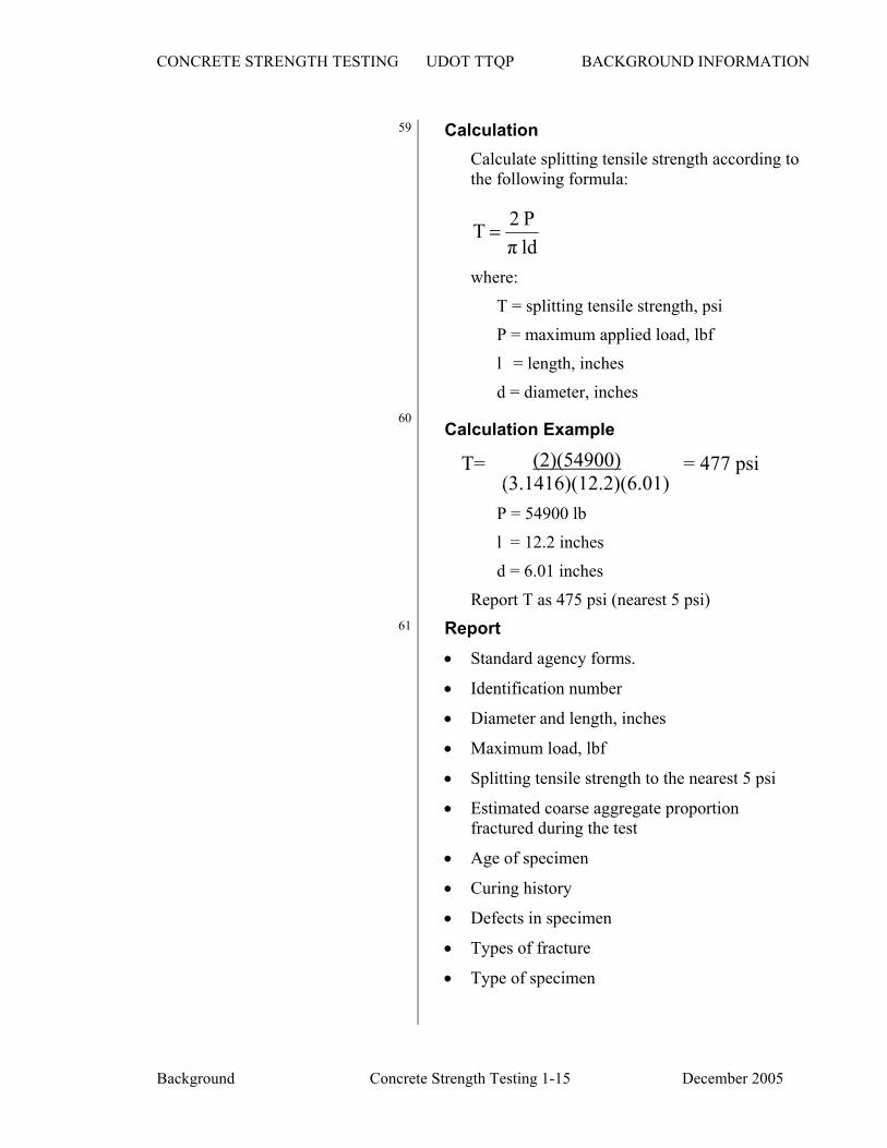
• Capping: Cap according to the applicable provisions of the FOP for AASHTO T 231 (presented later).
• Measurement: Measure diameter to the nearest 0.01 inch, and length after capping to the nearest 0.1 inch. Diameter measurements shall be taken at mid-height of the specimen and shall be the average of two measurements at right angles to each other. Do not test cores when the differences between the largest and smallest diameters exceed 5 percent of their average. Determine cross-sectional area.
• Testing: Test according to the FOP for AASHTO T 22. Test within 7 days of obtaining the core unless otherwise specified.
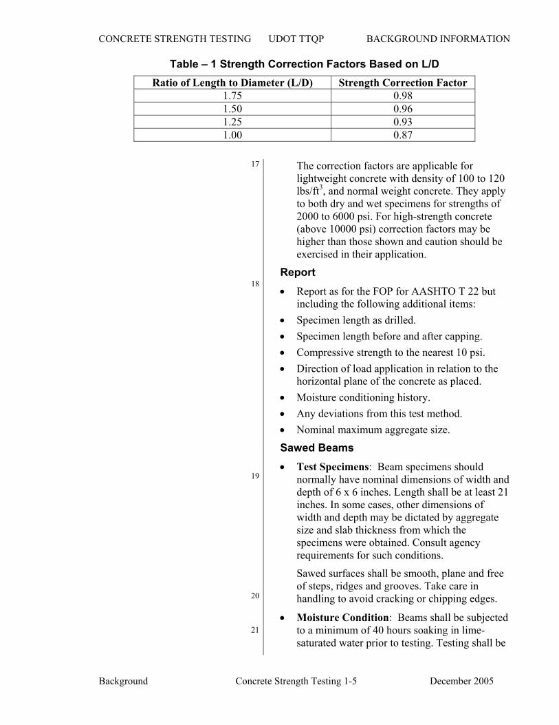
• Calculations: Calculate compressive strength of each specimen dividing the maximum load by the cross-sectional area. If the specimen L/D is between 1.9 and 2.1, no correction is required. Otherwise, correct according to the strength correction factors in Table 1.
CONCRETE STRENGTH TESTING UDOT TTQP BACKGROUND INFORMATION
Background Concrete Strength Testing 1-5 December 2005
Table – 1 Strength Correction Factors Based on L/D Ratio of Length to Diameter (L/D) Strength Correction Factor
1.75 0.98 1.50 0.96 1.25 0.93 1.00 0.87
17
18
The correction factors are applicable for lightweight concrete with density of 100 to 120 lbs/ft3, and normal weight concrete. They apply to both dry and wet specimens for strengths of 2000 to 6000 psi. For high-strength concrete (above 10000 psi) correction factors may be higher than those shown and caution should be exercised in their application.
Report • Report as for the FOP for AASHTO T 22 but
including the following additional items: • Specimen length as drilled. • Specimen length before and after capping. • Compressive strength to the nearest 10 psi. • Direction of load application in relation to the
horizontal plane of the concrete as placed. • Moisture conditioning history. • Any deviations from this test method. • Nominal maximum aggregate size.
19
20
Sawed Beams • Test Specimens: Beam specimens should
normally have nominal dimensions of width and depth of 6 x 6 inches. Length shall be at least 21 inches. In some cases, other dimensions of width and depth may be dictated by aggregate size and slab thickness from which the specimens were obtained. Consult agency requirements for such conditions.
Sawed surfaces shall be smooth, plane and free of steps, ridges and grooves. Take care in handling to avoid cracking or chipping edges.
21
• Moisture Condition: Beams shall be subjectedto a minimum of 40 hours soaking in lime-saturated water prior to testing. Testing shall be

CONCRETE STRENGTH TESTING UDOT TTQP BACKGROUND INFORMATION
Background Concrete Strength Testing 1-6 December 2005
22
23
conducted immediately after removal from moist storage and surfaces shall be kept continuously moist up to the time of testing.
When the agency permits or requires, moisture condition other than that described may be used prior to testing.
• Capping: Refer to FOP for AASHTO T 97 to determine if capping is required. If it is required, do so according to FOP for AASHTO T 231.
• Testing: Test according to FOP for AASHTO T 97. Since sawing may greatly reduce flexural strength, whenever possible orient the specimen for testing such that a formed or finished surface is the tension face.
Report • Report according to T 97 but include the
following additional items:
• Moisture condition at time of testing.
• Orientation of the specimen’s finished, sawed, and tension faces as positioned in the testing apparatus.
24 AASHTO R 39 – Making and Curing Concrete Test Specimens in the Laboratory
25
26
Introduction: AASHTO R 39 includes procedures for making specimens in the laboratory for many tests other than strength (creep, freeze thaw resistance, bond, length change, etc.).
This manual restricts the discussion to making specimens for compressive strength, flexural strength, and splitting tensile strength.
Much of the methodology described is the same as for molding strength specimens in the field (AASHTO T 23). Duplication of information will be avoided when possible except where clarity would be sacrificed.
Apparatus
• Molds: Molds shall comply with the applicable testing procedures under which specimens will be tested.

CONCRETE STRENGTH TESTING UDOT TTQP BACKGROUND INFORMATION
Background Concrete Strength Testing 1-7 December 2005
Slump Apparatus
27
28
29
30
31
Cylinder molds shall comply with AASHTO M 205.
Beam molds shall comply with AASHTO T 97. Note that laboratory-molded beam specimens may use molds with cross-section less than six by six inches when allowed by the governing agency. Consult agency specifications for guidance regarding mold dimensions.
• Tamping Rods: Large rod: 5/8” diameter, approximately 24 inches in length with a hemispherical tip. Small rod: 3/8” diameter, approximately 12 inches in length with a hemispherical tip.
• Mallets: Mallet with a rubber or rawhide head weighing 1.25 ±0.50 pounds.
• Vibrators: Internal vibrators shall operate at a minimum of 7000 vibrations per minute, shall have a length of at least 3 inches greater than the concrete layer being consolidated, and shall have a diameter of 0.75 to 1.5 inches. Table or plank vibrators shall operate at a minimum of 3600 vibrations per minute, and must permit secure clamping of the mold(s) to the apparatus.
• Small Tools: Shovels, scoops, trowels, etc. necessary for remixing and handling concrete mixtures.
• Slump Apparatus: Conforming to AASHTO T 119.
• Wet Sieving Apparatus: Conforming to the requirements of AASHTO T 141.
• Air Content Apparatus: Conforming to AASHTO T 152 or T 196.
• Scales: Accurate to 0.3% of the quantity of material being weighed.
Note 1: Avoid using scales of large capacity to weigh small material quantities. The smallest quantity weighed should generally be 10% or more of scale capacity or accuracy of batch proportions may suffer.
• Temperature Measuring Device: Conforming to the requirements of the FOP for AASHTO T 309.

CONCRETE STRENGTH TESTING UDOT TTQP BACKGROUND INFORMATION
Background Concrete Strength Testing 1-8 December 2005
Air Content Apparatus
32
33
34
35
• Concrete Mixers: Power operated mixer of the revolving drum, revolving pan, or revolving paddle type. Use size and type of mixer most suitable for the type and slump of mixture being produced (pan mixers may be more suitable for very low slumps for example).
Specimens • General: Diameter of cylinders or least
dimension of beams shall be at least three times the nominal maximum aggregate size. Occasional oversize pieces may be handpicked from the concrete mix; however, when the aggregate size is larger than appropriate, wet sieve the aggregate according to AASHTO T 141.
• Cylindrical Specimens: Minimum size of two-inch diameter by four-inch length. When correlation or comparison testing is desired for specimens cast in the field, 6 by 12 inch specimens shall be considered the standard.
Cylindrical specimens shall be cast and hardened in an upright orientation.
• Flexural Specimens: Form with long axes horizontal and meet requirements of AASHTO T 97.
• Number of Specimens: Mold at least three specimens from each batch for each test age. Consult agency guidelines for required test ages and series of mixtures required.
Preparation of Materials • Temperature: Bring temperature of concrete
materials to room temperature (68 to 86° F) prior to mixing.
• Cement: Keep cement dry. Remove lumps by passing through a No. 20 screen. Place cement on clean plastic sheet, mix thoroughly, and return to sample containers.
• Aggregates: For coarse aggregates, separate into individual size fractions and recombine according to aggregate grading.
For fine aggregate, keep in a damp condition to

CONCRETE STRENGTH TESTING UDOT TTQP BACKGROUND INFORMATION
Background Concrete Strength Testing 1-9 December 2005
36
37
38
prevent segregation unless it will be divided into separate sizes.
Prepare the aggregate such that a uniform moisture condition is achieved for each aggregate. Absorption of the aggregates must be determined according to AASHTO T 84 and T 85 to permit accurate adjustment of mix water to maintain desired water/cement ratio.
Aggregate Proportioning Determine weights for the batch by one of the following methods:
1. Low absorption coarse and fine aggregates (less than 1%): Determine mass of aggregates in a “room dry” condition and make allowance for the quantity of moisture that will be absorbed during the mixing process.
2. Weigh increments of coarse aggregates and immerse for 24 hours prior to use. Decant excess water and calculate combined aggregate and water weights required for the batch.
3. Bring coarse and fine aggregates to at least saturated-surface-dry (SSD) condition with the presence of a small amount of surface moisture such that excess water does not drain down from the aggregates. Determine moisture content of the aggregates and make adjustments to the batch to account for free moisture.
4. Bring coarse and fine aggregates to a SSD condition until batched for use. Avoid drying during weighing and use.
Lightweight Aggregates: Follow well-established procedures for acceptable handling and moisture conditioning of lightweight aggregates. Moisture condition of these aggregates may have important effects on the slump loss, strength, etc. of the concrete. In general it is desirable to assure at least partial saturation of the permeable pore spaces to prevent undesirable properties during and immediately after mixing.
Admixtures: Insoluble powdered admixtures not containing hygroscopic salts may be incorporated with the cement when batching. Those insoluble

CONCRETE STRENGTH TESTING UDOT TTQP BACKGROUND INFORMATION
Background Concrete Strength Testing 1-10 December 2005
39
40
powdered admixtures containing hygroscopic salts should be incorporated into the sand when batched.
Liquid admixtures should be added in the mixing water. Adjustment to batch water should be made to accommodate the liquid contained in the admixtures.
Pozzolans and other insoluble materials exceeding 10 percent by weight of cement should be batched as separate ingredients.
It is important to consult the admixture manufacturer to determine sequencing of admixture addition, or to determine whether some incompatibility exists between admixtures as undesirable effects may be noted in the mixed concrete.
41
42
43
Procedure – Mixing Concrete Only machine mixing is described. AASHTO R 39 also describes hand mixing for small quantities (less than ¼ cubic foot).
• General: Mix concrete of sufficient quantity such that at least 10 percent excess remains after casting specimens. Do not vary the mixing procedure from batch to batch unless that is the parameter being studied. Unless otherwise approved or required, use the following procedure:
1. Butter the mixer with a batch of similar proportions and discard the butter batch taking care that an excess of concrete does not remain in the mixer.
2. Add some of the mixing water, coarse aggregate and the liquid admixture to the mixer.
3. Start the mixer and add the fine aggregate, cement and remaining water.
4. Mix all ingredients for three minutes, after addition of the final ingredient. Allow the concrete to rest for three minutes, covering the mixer to prevent evaporation. Restart the mixer and mix for an additional two minutes.

CONCRETE STRENGTH TESTING UDOT TTQP BACKGROUND INFORMATION
Background Concrete Strength Testing 1-11 December 2005
Note 2: An experienced operator may add the final mix water incrementally to adjust to the desired slump.
44
45
46
• Mixed Concrete: Select portions of the batch to be used in tests and molding specimens to be representative of the proportions and condition of the concrete. Keep container covered except when remixing or obtaining portions for testing.
• Slump, Air Content, Density, Temperature: Determine according to AASHTO T 119, T 152 or T 196, T 121, and T 309 respectively.
• Making Specimens: Mold cylinders and beams according to AASHTO T 23 and T 97 using the number of layers and method(s) of consolidation specified.
• Curing Protection: Keep specimens covered to avoid loss of moisture. If wet burlap is used, prevent it from contacting the fresh concrete surfaces.
Removal From Molds: Remove from molds within 24 ±8 hours after casting.
Curing Environment: Unless otherwise required, continuously moist cure at 73.4 ±3° F until tested. Storage for the first 48 hours shall be in a location free of vibration.
Flexural Strength Specimens: Cure as described above, but immerse in lime-saturated water for at least the final 20 hours prior to testing.
47 AASHTO T 198 – Splitting Tensile Strength
of Cylindrical Concrete Specimens 48
Introduction
AASHTO T 198 describes the determination of splitting tensile strength of molded cylinders and drilled cores. This manual covers only those portions of the procedure applicable to specimens molded according to AASHTO T 23 or AASHTO R 39.
49
Summary of Method A diametral compressive force is applied at a controlled rate along the length of a cylindrical specimen until failure occurs. The loading applies

CONCRETE STRENGTH TESTING UDOT TTQP BACKGROUND INFORMATION
Background Concrete Strength Testing 1-12 December 2005
50
51
52
tensile stresses on the plane containing the applied load and relatively high compressive stresses in the zone immediately surrounding the applied load. Tensile failure occurs because the areas of load application are in a state of triaxial rather than uniaxial compression.
Thin plywood bearing strips are used top and bottom along the axis of the cylinder to assure uniform load application.
The maximum load is divided by appropriate geometrical factors to obtain splitting tensile strength.
Significance and Use Splitting tensile strength is easier to determine than direct tensile strength. It is used to help estimate the resistance to shear of reinforced lightweight concrete.
Apparatus • Testing Machine: Conforming to AASHTO
T 22.
• Supplementary Bearing Bar or Plate: Sufficient in length to apply the load to the longitudinal axis of the cylinder. Bearing surfaces shall be within 0.001” of a plane. Width shall be at least 2” and thickness shall be at least equal to the distance from the edge of the spherical or rectangular bearing block to the end of the cylinder.
• Bearing Strips: Two bearing strips of 1/8” nominal plywood at least 1 inch in width and at least equal in length to that of the specimen being tested. Strips are placed beneath and on top of the cylinder between cylinder and platen and bearing bars. Bearing strips may be used only once.
• Test Specimens: Conforming to size and curing requirements of T 23 or R 39. Moist cured specimens shall be kept moist by wet burlap or a wet blanket until time of testing. Lightweight specimens shall be initially

CONCRETE STRENGTH TESTING UDOT TTQP BACKGROUND INFORMATION
Background Concrete Strength Testing 1-13 December 2005
53 subjected to seven days of moist curing followed by 21 days of air-drying at 73.4 ±3°F at 50 ±5 percent relative humidity. They shall be tested in a dry condition.
54
55
Procedure • Marking: Draw diametral lines on each end of
the specimen to ensure that they are in the same axial plane (use of an aligning jig as shown in T 198 is helpful).
• Measurements: Determine the diameter of the test specimen to the nearest 0.01-inch by averaging three diameters measured near the ends and middle of the specimen, lying in the plane containing the diametral lines. Determine specimen length to the nearest 0.1 inch.
• Positioning Using Marked Diametral Lines:
1. Center one plywood bearing strip on the lower bearing block of the testing machine.
2. Place the specimen on the bearing strip and align so that the lines on the ends of the specimen are centered over the strip and are vertical.
3. Place the second bearing strip lengthwise on the top of the cylinder also centered on the lines.
4. Place the bearing bar or plate on top of the bearing strip.
5. The entire assembly must then be centered to coincide with the center of thrust of the spherically seated upper bearing block. Take care to maintain the lines vertical.

CONCRETE STRENGTH TESTING UDOT TTQP BACKGROUND INFORMATION
Background Concrete Strength Testing 1-14 December 2005
57
58
• Positioning Using Aligning Jig: Position the bearing strips, test cylinder, and supplementary bearing bar using the aligning jig (the jig keeps strips, cylinder, and bearing bar properly aligned). Place the entire assembly such that it coincides with the center of thrust of the spherically seated upper bearing block of the testing machine.
• Rate of Load Application: Apply the load continuously and without shock at a rate of 100 to 200 psi per minute splitting tensile stress until failure occurs. Record the maximum load sustained at time of failure. Note type of failure and appearance of the concrete.
Note: For a 6 by 12 cylinder the rate of loading is approximated by 11,300 to 22,600 lbf per minute.
56
CONCRETE STRENGTH TESTING UDOT TTQP BACKGROUND INFORMATION
Background Concrete Strength Testing 1-15 December 2005
59 Calculation
Calculate splitting tensile strength according to the following formula:
ldπP 2 T =
where:
T = splitting tensile strength, psi
P = maximum applied load, lbf
l = length, inches
d = diameter, inches 60 Calculation Example
(2)(54900) (3.1416)(12.2)(6.01) P = 54900 lb
l = 12.2 inches
d = 6.01 inches
Report T as 475 psi (nearest 5 psi) 61 Report
• Standard agency forms.
• Identification number
• Diameter and length, inches
• Maximum load, lbf
• Splitting tensile strength to the nearest 5 psi
• Estimated coarse aggregate proportion fractured during the test
• Age of specimen
• Curing history
• Defects in specimen
• Types of fracture
• Type of specimen
T= = 477 psi

CONCRETE STRENGTH TESTING UDOT TTQP BACKGROUND INFORMATION
Background Concrete Strength Testing 1-16 December 2005
62
AASHTO M 201 – Mixing Rooms, Moist Cabinets, Moist Rooms, and Water Storage Tanks Used in the Testing of Hydraulic Cements and Concretes
63 Introduction AASHTO M 201 covers the specification for mixing rooms, moist cabinets, moist rooms and water storage tanks for curing hardened concrete specimens up to the time of testing.
64 Terminology • Mixing rooms have controlled temperature
and relative humidity where cement paste and mortar specimens are prepared.
• Moist cabinets are moderately sized storage facilities in which temperature and moisture conditions are closely controlled.
• Moist rooms are larger “walk-in” storage facilities also with closely controlled temperature and humidity.
65
66
67
Requirements for Cement Mixing Rooms • Air temperature maintained at 73.4 ±7°F,
relative humidity not less than 50%.
• Mixing water temperature used to prepare cement paste and mortar specimens shall be 73.4 ±3°F.
Requirements • General for Moist Rooms and Moist
Cabinets: The atmosphere must have a temperature of 73.4 ±3°F and a relative humidity of at least 95 percent. The humidity must be sufficient that all exposed surfaces of test specimens have free moisture on them.
Records of temperature must be maintained using a recording thermometer that is calibrated at a maximum interval of six months or whenever accuracy is suspect. (Verification of the recording thermometer shall be performed using a reference thermometer accurate and readable to 0.9° F.) Verification

CONCRETE STRENGTH TESTING UDOT TTQP BACKGROUND INFORMATION
Background Concrete Strength Testing 1-17 December 2005
68
69
70
71
shall be made according to the following procedure.
1. Position reference thermometer as close as possible to the sensor of the recording thermometer.
2. Close the door to the moist cabinet or room for at least five minutes.
3. Record both the temperature reading of the reference thermometer and the recording thermometer (Take the reference thermometer reading in the moist cabinet or room immediately upon opening the door).
4. Compare the results of the two readings. If the difference is greater than 1.8°F the recording thermometer must be adjusted to within 0.9°F of the reference thermometer reading.
5. Archive the recordings of the recording thermometer in order to prove that proper control over curing temperature is being exercised.
Shelves on which fresh specimens are placed must be level.
Air temperature must be positively controlled by either heating or cooling as required according to one of the following two methods:
1. Thermostatically control the air inside the storage facility (thermostat must be inside the facility).
2. Thermostatically control the air surrounding the facility and manually control the air temperature inside the facility.
• Moist Cabinets: Moist cabinets must be constructed of durable materials with a tight-fitting door. They must have at least one or more fog sprays, water sprays, or curtains of water on the inner walls such that water discharge will be collected in a pool near the bottom.
• Moist Rooms: Walls must be constructed of durable materials with tight-fitting doors, and windows, if any.

CONCRETE STRENGTH TESTING UDOT TTQP BACKGROUND INFORMATION
Background Concrete Strength Testing 1-18 December 2005
72
73
74
Humidity may be achieved in any convenient way such as fog sprays, atomizing humidifiers, etc.
Moist rooms used in cement testing must have durable shelving manufactured in such a way as to prevent droplets of water from falling on freshly made specimens.
Moist rooms used in concrete testing shall maintain atmospheric conditions such that free moisture is maintained on all exposed specimen surfaces. Specimens may not be exposed to running or dripping water.
• Water Storage Tanks: Tanks must be constructed of non-corroding material. Each tank not contained in a room capable of maintaining the required temperature range shall be equipped with positive temperature controls to maintain 73.4 ±3o F, and shall have a recording thermometer with the sensor immersed in the storage water. Recording thermometers shall be calibrated at an interval not exceeding six months. The calibration thermometer shall be placed adjacent to the sensor of the recording thermometer and the temperatures compared. If the recording thermometer indicates a temperature more than 1.8°F different from that of the calibration thermometer, the recording thermometer shall be adjusted such that the readings agree within 0.9°F.
Water in the storage tanks shall be saturated with calcium hydroxide such that excess calcium hydroxide is present. Water in the tanks shall be stirred at least monthly and shall be refilled with fresh solution at intervals not exceeding 24 months (The solution must contain 3g/L of calcium hydroxide).
To prevent leaching of minerals from test specimens do not use continuously running water or demineralized water in storage tanks.

CONCRETE STRENGTH TESTING UDOT TTQP BACKGROUND INFORMATION
Background Concrete Strength Testing 1-19 December 2005
75 AASHTO M 205 – Molds for Forming
Concrete Test Cylinders Vertically 76 Introduction
AASHTO M 205 covers the specification for single-use and reusable cylinder molds. Sizes include those with nominal diameters from 2 to 36 inches. The most commonly used sizes for concrete testing have nominal diameters of four and six inches. Cylinder molds are those for forming cylindrical specimens vertically (having an open top for filling with concrete).
77
78
General Requirements Molds shall be right circular cylinders constructed of materials that do not react with concrete containing portland cement or other hydraulic cements. Molds must be water tight and strong enough to resist crushing, tearing, or otherwise deforming.
The nominal inside height shall be twice the diameter. Height consisting of the average of two measurements 180 degrees apart shall not differ from the nominal height by more than 2%. Diameter at the top of the mold shall not differ by more than 1% from the nominal diameter (diameters consist of the average of two measurements at right angles to one another). Planes of the top and bottom may not deviate from perpendicularity to the axis by more than 0.5 degrees (1/8” in 12”). No diameter of a mold may differ from any other diameter by more than 2%. The bottom inside surface of the mold may not depart from a plane by more than 1% of the mold diameter (approximately 1/16” in 6”).
79
• Reusable Molds Molds must be made of non-absorptive materials and may consist of one or more pieces. Many materials are satisfactory provided that they meet the requirements, but alloys of aluminum and magnesium are not permitted since they may react with constituents of the portland cement concrete. Molds must be tested for water leakage and strength as noted below for single-use molds

CONCRETE STRENGTH TESTING UDOT TTQP BACKGROUND INFORMATION
Background Concrete Strength Testing 1-20 December 2005
80
after every 50 uses or every 6 months, whichever comes first.
Molds must have a base at right angles to the axis. They may be constructed of a single piece, or made from castings with separate detachable base. If an inside fillet is used at the bottom of the sidewall, the vertical and horizontal legs may not have lengths exceeding 1/8” and 3/16” respectively. Molds must be either coated or manufactured of material that will prevent adherence to concrete. Molds must be watertight at time of use.
81
82
83
• Single-Use Molds General: Single-use molds may be made of paper, sheet metal, plastic, or other materials.
Physical requirements – When tested for water leakage, they shall show no visible leakage. Absorption shall not exceed values presented in Table 1 below. Elongation shall not exceed 0.002 in./in. (0.2%) of height.
• Paper Molds: Sidewalls of paper molds shall be constructed with a minimum of three plies with a total thickness of at least 0.070 in. Seams on the inside of the mold may not be open by more than 1/16 in.
Bottom caps shall be either metal or paper. If made of metal, minimum thickness shall be 0.009 in. and coated to prevent corrosion. The bottom shall be flush with the bottom of the sidewall within 1/16 in. The inside crimp shall produce an indentation not to exceed 3/16 in. horizontally or 1/8 in. vertically. If the bottom cap is made of paper, it shall be made of parchment lined cap stock at least 0.028 in. thick and shall be glued to the outside of the walls by means of a flange at least ¾ in. high.
Waterproofing material shall completely coat the inside and outside of sidewalls and bottom. The top edge shall also be waterproofed to prevent absorption. Waterproofing must have a melt point not lower than 120oF.

CONCRETE STRENGTH TESTING UDOT TTQP BACKGROUND INFORMATION
Background Concrete Strength Testing 1-21 December 2005
84
85
86
• Sheet Metal Molds:
Metal thickness of sidewalls shall be equivalent to can-making blackplate with a minimum metal thickness corresponding to 107-lb. blackplate approximately 0.0118 in. thick. Minimum metal thickness of the bottom shall be 0.009 in.
Bottom design – The bottom shall be flush with the bottom of the sidewall within 1/16 in. If used, the inside crimp shall produce an indentation not to exceed 3/16 in. horizontally or 1/8 in. vertically.
Top edge – Curled or beaded to strengthen the mold and protect the user from cuts. If the curl or bead extends inside the mold it shall not make an indentation exceeding 1/8” either horizontally or vertically.
Coating – If material used in manufacture will rust or corrode, it must provide a protective coating (lacquer or other suitable material).
• Plastic Molds:
Wall thickness shall be sufficient to meet the strength and dimensional tolerances outlined under “General Requirements” above.
Bottom design – Flush with the bottom of the sidewall within 1/16 in. If used, an inside fillet may not result in an indentation greater than 1/8 in. vertically or 3/16 in. horizontally. The bottom must be sufficiently rigid to produce specimens complying with the applicable provisions of T 23 and R 39.
Material – Maximum water absorption of 0.5% in 24 hours as tested by ASTM D 570; Izod impact toughness of at least 2.2 ft-lb per inch of notch for 1/8 in. thick specimen as tested by ASTM D 256; after holding at 10oF, for 24 hours the plastic shall not fracture when subjected to tapping and jarring considered to be typical when specimens are being molded.

CONCRETE STRENGTH TESTING UDOT TTQP BACKGROUND INFORMATION
Background Concrete Strength Testing 1-22 December 2005
87
88
89
90
Test Methods for Elongation, Absorption, and Water Leakage Apparatus See Figure 2 of AASHTO M 205.
• Specimens: Select molds according to the section “Sampling and Rejection.” For single-use molds, do not reuse or retest when conducting the following test methods.
• Test Procedure for Molds: Subject all molds to the dry rodded coarse aggregate test to evaluate damage during use. Paper or other absorptive molds shall be tested for absorption, elongation, and water leakage. Molds that are obviously non-absorptive (lightweight sheet metal molds for example) do not need to be tested for absorption and elongation, but shall be tested for water leakage. Verify dimensional requirements for all types of molds.
Dry Rodded Coarse Aggregate Test – Fill the mold with either No. 57 (1” to No. 4) or No. 67 (3/4” to No. 4) crushed coarse aggregate. Use the method of compaction, number of layers, and strokes of the rod as required by AASHTO T 23. After rodding the final layer, empty the material from the mold, wipe the inside of the mold with a dry cloth, and inspect for physical damage.
Elongation, Absorption, and Water Leakage –1. Complete the dry rodded procedure
2. Weigh the mold to the nearest 0.1 g/in. of mold height.
3. Place the mold on a firm, flat surface and fill with room-temperature water to approximately 90 to 95% of height.
4. Place the mold on the dial stand as shown in M 205, Figure 2, cover with a glass plate and record the initial length of the filled mold to the nearest 0.001 in.
5. Allow the mold to stand for three hours and take a final length reading.
Note: It will probably not be possible to completely penetrate each layer during the rodding process. The effort given in the rodding attempt will suffice for the requirements of this procedure.

CONCRETE STRENGTH TESTING UDOT TTQP BACKGROUND INFORMATION
Background Concrete Strength Testing 1-23 December 2005
91
6. Examine the mold for any leakage and record observations.
7. Empty the mold, dry with a towel and record the final mass of the empty mold to the nearest 0.1 g/in. of height.
8. Calculate the elongation as the difference between the final and original length.
9. Calculate absorption as the difference between the final and initial mass of the mold.
10. Verify mold dimensions again.
11. Evaluate elongation and absorption to assure compliance. See Table 1.
Table 1 – Limits for Absorption and Elongation
Nominal Mold Height, in. Maximum Absorption, g Maximum Elongation, in. 4 2.7 0.008 6 6.0 0.012 8 11 0.016
12 24 0.024
93 Water Leakage for Assembled Reusable Molds Assemble molds with sealant if required. Fill molds to a depth of 90 to 95% of the height and subject the mold to tapping and jarring equivalent to that of molding specimens according to T 23. One hour after jarring and tapping, examine for leaks.
94
Sampling and Rejection
• At least three single-use and reusable molds shall be randomly selected from each shipment by the purchaser to conduct specified tests for compliance with this specification.
• Failure of any one of the three molds shall be basis for rejection of the shipment.
92

CONCRETE STRENGTH TESTING UDOT TTQP BACKGROUND INFORMATION
Background Concrete Strength Testing 1-24 December 2005
95
96
Report • Brand and source of mold.
• Shipment or lot number.
• Date sampled and date tested.
• General mold description: Nominal dimensions, type of mold, materials from which constructed.
• Applicable test results: Total absorption, g.; total expansion, in.; water leakage.
• For failed molds report the following (if applicable):
- Average diameter or height, in.
- Maximum and minimum diameters or lengths, in.
- Nonconformance with perpendicularity of rim or base to axis
- Apparent reaction between mold materials and concrete or mortar
- Melting point of coatings less than 120o F
- Minimum thickness of materials in sidewall and bottom
- Dimension of crimp in bottom, top edge, or construction of paper bottom