management of radioactive waste from nuclear …
TRANSCRIPT

lAEA-TECDOC- 276
MANAGEMENTOF RADIOACTIVE WASTE
FROM NUCLEAR POWER PLANTSPROCEEDINGS OF A SEMINAR
ON THE MANAGEMENT OF RADIOACTIVE WASTEFROM NUCLEAR POWER PLANTS
ORGANIZED BY THEINTERNATIONAL ATOMIC ENERGY AGENCY
AND HELD IN KARLSRUHE, 5-9 OCTOBER 1981
A TECHNICAL DOCUMENT ISSUED BY THEINTERNATIONAL ATOMIC ENERGY AGENCY, VIENNA, 1983

The IAEA does not maintain stocks of reports in this series. However,microfiche copies of these reports can be obtained from
IN IS Microfiche ClearinghouseInternational Atomic Energy AgencyWagramerstrasse 5P.O. Box 100A-1400 Vienna, Austria
on prepayment of Austrian Schillings 40.00 or against one IAEA microficheservice coupon.

MANAGEMENT OF RADIOACTIVE WASTE FROMNUCLEAR POWER PLANTS
IAEA, VIENNA, 1983IAEA-TECDOC-276
Printed by the IAEA in AustriaJanuary 1983

Please be aware that all the Missing Pages
in this document were originally blank pages

FOREWORD
More than 250 power reactors are now in operation throughout theworld, a further 230 are under construction or planned, and, in the longrun, nuclear energy is expected to play an increasingly important role inthe development of national energy programmes. During the course ofroutine operations of nuclear power reactors used to generate electricalenergy, radionuclides are produced by fission and neutron activation.These radionuclides come into contact with normal plant streams with thesubsequent creation of various radioactive wastes. The greater part ofthese wastes can be classified as low- and intermediate-level.Appropriate handling, treatment and disposal of these wastes is anactivity of particular importance to assure protection of man and hisenvironment from unacceptable harm.
In response to the growing interest in these topics as a result ofthe increasing use of nuclear power, the International Atomic EnergyAgency, in co-operation with the Government of the Federal Republic ofGermany, held a Seminar on Management of Radioactive Waste from NuclearPower Plants in the Nuclear Research Centre Karlsruhe, 5-9 October 1981.It provided technical experts involved in waste management at nuclearpower plants an opportunity of exchanging information on their operatingexperience, and discussing the specific problems in every country.
Over 190 participants from 28 Member States and four InternationalOrganisations attended the Seminar and 40 papers were presented.
Technical improvements are being accomplished and research work iscontinuing, particularly with a view to improve safety and economy.Among the topics, whose progress was discussed at the Seminar, were:
gaseous, liquid and solid waste handling and treatment;- conditioning of liquid and solid waste;- management of waste arising from decontamination of nuclear power
plants and accident situations;- transport, storage and disposal of waste arising at nuclear power
plants.
Emphasis was laid on waste conditioning methods with respect toimprovements in volume reduction, quality control of solidified wasteforms, low sensitivity to the waste composition and disposal conditions.

Regarding radioactive disposal, at present underground disposal isconsidered to be the most feasible method for safe disposition of low-and intermediate-level wastes from nuclear power plants. Consequently,the main disposal options for these wastes like emplacement in rockcavities and shallow ground burial were discussed.
The opinion of most nuclear experts is that the practice of handlingand treatment of radioactive waste from nuclear power plants has beensafely demonstrated for the past several decades. Satisfactory methodsfor disposing waste from nuclear power plants are available in principleand great efforts should be made to establish such methods in practice.
These Proceedings contain mainly papers that describe nationalpractices in a considerable number of Member States on technical,technological and operative aspects associated with the management ofradioactive waste arising from nuclear power plants under normal andaccident situations. A round-table discussion is also included.

CONTENTS
The role of wastes from nuclear power plants in the overall management of radioactivewastes...................................................................................................................................... 9H. Krause
Development of a policy and strategy for the management of radioactive wastes from theUK civil power stations............................................................................................................ 21R.B. Pepper
Practice in management of radioactive waste from nuclear power plants in Czechoslovakia ........ 31E. Maldsek, E. Hladky, L. Tomic
Retrofit of radioactive waste capability to an operating nuclear power station — Indianexperience............................................................................................................................... 43N.K. Bansal, K. Balu
Traitement et conditionnement des effluents et déchets radioactifs des centrales nucléairesfrançaises à eau pressurisée ...................................................................................................... 53/. Céleri, P. Po t tier, Y. Sousselier
Radioactive waste management practices at a large Canadian electrical utility ............................. 73T.J. Carter
USDOE activities in low-level radioactive waste treatment .......................................................... 99J.E. Vath
Experiences in the treatment of radioactive wastes in nuclear power plants in the FederalRepublic of Germany .............................................................................................................. 105R. Ambros, H. Hepp, Th. F. Kierile, D. Rittscher
Management of radioactive waste at Swedish power plants.......................................................... 121H. Forsström, S. Gustafsson, B. Persson, J. Ransmark, C. Thegerström, G. Wickström
Status and improvement of the removal of airborne particulates and radioiodine ...................... 135J.G. Wilhelm
Aspects technico-économiques de la gestion des déchets dus au fonctionnement descentrales PWR ......................................................................................................................... 149J. Lepine, J.P. Langlois, M. Beunardeau, C. Métairie
Experience gained in the management of radioactive waste from maintenance, decontaminationand partial decommissioning of a reprocessing plant and conclusions resulting for themanagement of radioactive wastes from nuclear power plants ................................................. 165W. Hild
Waste amounts and waste treatment at the decommissioning of nuclear power plants ................. 187P. Petrasch
L'expérience industrielle française sur le stockage en sub-surface des déchets radioactifs descentrales nucléaires .............................................................................................................. 199J.M. Lavie, A. Barthoux, Y. Marque, A. Careyron, P. Regimbeau
Disposal of radioactive wastes from nuclear power plants in the Federal Republic of Germany... 213P. Brennecke, E. Warnecke
A central repository for final disposal of the Swedish low- and intermediate-level reactorwastes...................................................................................................................................... 227G. Lange

ABSTRACTS OF OTHER PAPERS PRESENTED AT THE SEMINAR
(texts of these papers can be requested directh from the authors)
Management of radioactive wastes from nuclear power stations in the USSR ............................. 247A.S. Nikiforor, M.I. Zhikharev, V.I. Zemlyanukhin, V. V. Kulichenko, I.E. Nakhutin,A.S. Polyakor. N.A. Rakov
Proposal on an advanced radioactive waste system ...................................................................... 247Y. Koshiba. H. Kuribayashi. S. Shibata
Research on evaporation of nuclear power plant waters with the pilot plant evaporator atthe Loviisa nuclear power plant .............................................................................................. 248A. Muurinen, 0. Räsänen, I. Kallonen, J. Söderman, M. Järveläinen
An auxiliary demineralization system for liquid radioactive waste .............................................. 249M.H. Lin, C.R. Win, J.C. Ritchie
The pilo process: zeolites and titanates in the treatment of spent ion exchange resins ............... 249A Hultgren, C. Thegerström, S. Forberg, T. Westermark, L. Fait
' Nouvelles applications des résines thermodurcissables dans le domaine des déchetsradioactifs................................................................................................................................ 251G. Aude, C. de Tassigny
Development of drying and pelletizing technique for radioactive waste ...................................... 252S. Horiuchi, T. Saito, M. Hirano, M. Kikuchi, K. Chino, K. Kudo, M. Hayashi
Conditioning CANDU reactor wastes for disposal ....................................................................... 252N. V. Beamer, W. T. Bourns, L.P. Buckley, R.A. Speranzini
Cement solidification of BWR- and PWR-bead resins .................................................................. 253H. Christensen
Treatment of spent ion-exchange resins I-INSHAS reactor resins................................................. 253N.K. Ghanas, S.£. Eskander, N.E. Ikladious
Performance of bituminized aqueous radioactive wastes ............................................................. 254A.S. Williamson
Expérience acquise dans le conditionnement et la lixiviabilité des déchets PWR enrobés parle ciment ................................................................................................................................. 254A. Bernard, J. C. Nominé
Characterization of solidified reactor waste products. Work carried out at Studsvik1978-1981 ............................................................................................................................. 255J.P. Aittola, R. Sjöblom
Treatment, monitoring and on-site storage of solid waste at the Olkiluoto BWR nuclearpower plant ............................................................................................................................. 255A.A. Toivola
New Hungarian technology for the treatment and transport of radioactive wastes ...................... 256K. Szivôs, F. Takdîs, F. Gulyâs, I. Pajer
Venting krypton-85 from the Three Mile Island Unit 2 Reactor Building .................................... 257KM. Burton
Characterization of radioactive ion exchange media waste generated at Three Mile Island .......... 257T.C. Runion, R.E. Holzworth, R.E. Ogle, KM. Burton, W.W. Bixby, C.P. Deliete
Development of a high integrity container for storage, transportation and disposal ofradioactive wastes from Three Mile Island Unit 2 .................................................................. 258R.E. Holzworth, R.L. Chapman, KM. Burton, W.W. Bixby, D. Buchanan
Management of post accident air borne radioiodine containment system in India ....................... 259A.A. Khan, S.D. Deshingkar, S.K. Samanta, K.G. Gandhi
Status of Three Müe Island Unit 2 cleanup .................................................................................. 259F.E. Coffman

Construction of a cavity for disposal of medium level waste at the Asse Salt Mine ..................... 260H. Kolditz, M. Schmidt, H.-F. Schwaegermann
Transport of radioactive waste from nuclear power plants .......................................................... 261H.-J. Engelmann
Round Table Discussion .............................................................................................................. 263Chairmen of Sessions ................................................................................................................... 279List of participants and the Designating Member States. Organizations and Secretariat ............... 281

THE ROLE OF WASTES FROM NUCLEAR POWERPLANTS IN THE OVERALL MANAGEMENT OFRADIOACTIVE WASTES
H. KRAUSEKernforschungszentrum Karlsruhe GmbH.Institut für Nukleare Entsorgungstechnik,Karlsruhe.Federal Republic of Germany
Abstract
The wastes a r i s ing from nuclear power plants (NPP) are rather low in acti-vity and the radionucl ides contained therein have a low radiotoxicity and shorth a l f - l i f e as a rule. However, NPPs are the largest in number among all nuclearfaci l i t ies and produce the greatest amount of radioactive wastes.
All NPPs have been able to keep the radiat ion doses in the environment belowthe permissible values, in most cases at 1 mrem/a or even lower.
The methods applied for the treatment of l i q u i d radioactive effluents havereached a high degree of effectivity and re l iab i l i ty . For the so l id i f i ca t ion ofthe residues several appropriate methods are ava i lab le . However, some improve-ments are s t i l l desirable.
Although methods exist for incinerat ion, cutt ing and ba l ing of solid wastesonly the last method is employed at NPPs as a rule . Central treatment faci l i t t iescould improve this s i tuat ion.
The exhaust air treatment has reached a state that satisfies high standardsduring normal operation and in design base accid.ents. Improvements seem indicatedregarding the in situ-inspection of HEPA-filters and the protection of filtersagainst excess humidi ty and droplets.
The partial and total decommissioning of NPPs has already been demonstrated.The problems caused by the wastes a r i s ing from such actions are in the samerange as those from routine operation and maintenance of NPPs.
Large amounts of radioactive wastes have already been disposed of by sha l lowland bu r i a l , disposal into deep geological formations or dumping into the deepsea. Specific standards could probably faci l i ta te the disposal of wastes from NPPs.
The present management of radioactive wastes from NPPs satisfies all actualneeds. Therefore, spectacular new developments are neither required nor to beexpected. However, by the continuous improvement of details and by optimization ofthe whole system progress can s t i l l be achieved and useful contributions to thefurther development of nuclear energy be made.
I n t r o d u c t i o n
S i n c e more t h a n 2 0 y e a r s a n i n c r e a s i n g n u m b e r o f n u c l e a r p o w e rp l a n t s ( N P P ) h a s b e e n i n o p e r a t i o n a r o u n d t h e w o r l d . I n t h e e a r l yy e a r s , t h e r a d i o a c t i v e w a s t e s were m a n a g e d i n a r e l a t i v e l y s i m p l ew a y a t some N P P s a s c o m p a r e d t o t h e a c t u a l p r a c t i c e . H o w e v e r , f r o mt h e b e g i n n i n g , t r e a t m e n t h a s been s o c a r e f u l t h a t t h e s t a n d a r d sse t up by t he a u t h o r i t i e s f o r t he d i s c h a r g e o f r a d i o n u c l i d e s i n t othe e n v i r o n m e n t h a v e been m e t . Up t i l l now the t echno logy fo r thet r e a t m e n t o f r a d i o a c t i v e w a s t e s h a s c o n t i n u o u s l y i m p r o v e d . I n t h i s

way it has been p o s s i b l e to reduce further the discharges of ra-d i o n u c l i d e s into the environment. The treatment of NPP-wastes hasbecome a routine. Not even one serious accident has resulted fromthe waste management a c t i v i t i e s in NPPs. The dose commitment tothe operators has been kept within the established l i m i t s .
The r a d i o a c t i v e wastes a r i s i n g at NPPs are relatively low ina c t i v i t y ; the h a l f - l i v e s of the radi onucl i des contained in thesewastes are rather short and their radiotoxicity is low. The amountof waste produced at each i n d i v i d u a l NPP is moderate. Because ofthese facts the wastes from NPPs are considered rightly as posingno big technical or safety problem and usually only l i t t l e atten-tion is p a i d to them. However, this is not justified as thesewastes represent all together the largest amount of all radioactivewastes and since some of them also c a l l for further improvement.
In this paper an attempt, is made to relate the importance ofthe wastes from NPPs to that from other nuclear facilities, toevaluate the actual state of the art in this field and to pointout areas that need further development.
Amounts, Activities and Toxicity of Wastesfrom NPPs
At the end of 1980, 254 NPPs were in operation in the" wholeworld with an installed capacity of 138,000 MWe. 234 facilitieswith an installed capacity of 217,000 MWe were under constructionand another 96 plants with 95,000 MWe were ordered (Tab. I). Withthese figures given, the number of NPPs by far exceeds that of allother nuclear facilities [1]. In many countries the wastes fromNPPs, besides those from nuclear research facilities, are the onlywastes that occur at present and are expected to occur in the nearfuture.
The amounts of radioactive wastes arising at each i n d i v i d u a lNPP are not very large but taken together they constitute - withthe exception of those from uranium m i l l s - by far the largestamounts (Fig. I ). Also, in relation to a given installed nuclearcapacity, NPPs produce the greatest amount of radioactive wastes[2],Improvements in the fabrication of fuel elements and in the designand operation of NPPs have led to a considerable reduction of theactual production of radioactive wastes compared to that in ear-lier years [2], Different types of reactors show distinct diffe-rences both in the arising waste and in the discharge of radio-n u c l i d e s into the environment. However, these differences are notbig enough to give preference to a certain type of reactor on thebasis of these aspects.
10

A l t h o u g h the quasi-totality of all a r t i f i c i a l r a d i o n u c l i desis produced in nuclear reactors, they are so well contained thatthe radioactivity of the wastes from NPPs is relatively small ascompared, es p e c i a l l y , to that of the wastes from the reprocessingof spent nuclear fuels (Fig. I), but it is h i g h enough to justifythe careful treatment whi c h radioactive wastes receive everywhere.
Fig. II is a comparison of the hazard index of the wastefrom NPPs with thet of h i g h level waste. It shows that the hazardindex of wastes from NPPs is rather low from the beginning and hasdecayed to innoxious l e v e l s w i t h i n a few hundred years, due tothe low activity, low radiotoxicity and the short h a l f - l i v e s ofthe radi o n u c l i des.
Environmental Impact of the Effluents from NPPs
In all NPPs it was possible to keep the radiation dose commit-ment to the environment caused by the discharge of l i q u i d and ga-seous effluents below the permissible limits established by theauthorities. In most cases the resulting dose commitment at thepoint of maximum exposure outside the plants was about or evenbelow 1 mrem/a [3]. In the course of the past years there haseven been a general further decrease in the amounts of r a d i o a n u c l i -des released. A further reduction, however, cannot be obtainedeasily in installations that have already achieved a low rate ofdischarge. As a matter of fact, there is no strict necessity forthis, although it is desirable in principle to reduce as much aspossible the radiation dose commitment to the population. Furtheractions in this direction have to consider the cost-benefit aspectunder which also the dose commitment to the personnel caused bynew or additional actions must be taken into account.
The State of the Art in the Field of Treatment ofRadioactive L i q u i d Effluents
The treatment of radioactive l i q u i d effluents has reached ahigh technical standard. It hardly needs further improvement.Improvements are desirable only in some older waste treatmentplants l i k e in many other old nuclear facilities with respectto ease of maintenance.
The methods applied such as evaporation, ion exchange andchemical flocculation are effective in terms of decontaminationfactors, volume reduction and reliability. As these methods arewell known they w i l l not be discussed here in detail [4,5].
11

Although evaporation achieves the highest decontaminationfactors among all treatment processes, it does not seem necessarythat evaporation replaces chemical precipitation or the simple filtration totally, e.g. in the treatment of some special low activeeffluents, as from showers or laundries. However, it should beexamined whether the substitution of ion exchange by evaporationc o u l d lead to a further decrease in volume of the residues and toa h i g h e r q u a l i t y of the conditioned final products. Other methodssuch as reverse osmosis, electromagnetic filters, or centrifugalclarifiers, are s t i l l under development or in early stage ofa p p l i c a t i o n . Some of them look q u i t e p r o m i s i n g .
Solidification of Haste Concentrates
For the s o l i d i f i c a t i o n of the waste concentrates arising fromthe decontamination of l i q u i d effluents several appropriatemethods are a v a i l a b l e , such as the incorporation into cement,bitumen and plastics [5].
The fixation in cement is in principle a simple and cheapmethod. Nevertheless, some NPPs have concluded contracts withprivate companies to solidify their radioactive waste concentratesin m o b i l e facilities in order to save labor and investment costs.Cementation is actually the frequent method used for the condi-tionning of waste concentrates.
A main disadvantage of cementation is the doubling of thewaste volume. This may be neglected as long as sufficient andcheap disposal capacity exists, but if not this aspect becomesrather important. The quality of the cemented residues is suffi-cient for most kinds of waste and disposal options. However, itcannot be neglected that, for instance, ion exchangers do notgive products very stable mechanically. As a rule, the cementedwastes have relatively high leach rates. Some l i q u i d effluents,e.g. those containing boric acid or detergents, can retard thehardening of the cement. By a special treatment with appropriateadditives most of these problems can normally be eliminated.
The bituminization is superior to cementation in many respects[6]. Nevertheless, it has been employed in NPPs to a small extentonly up t i l l now. In comparison with cementation a volume reduc-tion by a factor of 2-6 is achieved. Also, the leach resistanceof the final products is usually better. A disadvantage, howeverwithout too much practical importance, is the inflammability ofbitumen. A further and more important disadvantage lies in theh i g h investment costs. However, this aspect becomes less important
12

in case of h i g h storage, transport and disposal costs, so thatpossibly the a p p l i c a t i o n of bituminization w i l l increase in future.
The s o l i d i f i c a t i o n of waste water concentrates with urea-for-maldehyde is used in some NPPs, esp. in the USA [7]. Sometimesproblems occur with this process, e.g., by incomplete b i n d i n g ofwater. Neither the mechanical stability nor the leach resistanceis very good.
Organoplastics (polyesters, epoxy-resins and polystyrene) arealso used for the fixation of waste water residues. Polystyreneand divinylbenzene have proved to be well s u i t a b l e for thefixation of ion exchange bead resins. In the Federal R e p u b l i cof Germany it is often used im mobile facilities. The method isvery simple; it is sufficient to pour the monomers plus a catalystover the bead resins at room temperature.
The use of thermosetting polyesters and epoxy resins is atechnique developed mainly in France. In p r i n c i p l e , evaporatorconcentrates, sludges and ion exchange resins can be embedded,into these resins. Evaporator concentrates have to be transformedinto a dry product prior to incorporation. In order to reduce theleach rates a preceding precipitation is recommended. The polyme-risation is carried out at room temperature, too. Vinylesters havebeen developed in the USA for'the fixation of reactor wastes. Alsoin some other countries plastics are employed or under developmentfor this pupose.
Although the methods and products a v a i l a b l e actually for thes o l i d i f i c a t i o n of waste water residues generally meet the require-ments, they cannot be considered yet as ide a l and improvements interms of volume reduction, product control, i n s e n s i b i l i t y to thewaste composition, costs and sometimes even product quality aresti l l desirable. It w i l l however not be easy to develop such anideal product which satisfies all demands esp. as the large volumesand the low risk potential of these wastes do not allow for toosophisticated processes. Recent experience has shown that for thefixation of waste residues with a relatively h i g h activity levelas they may arise after great accidents (e.g. the Three Mile Islandaccident) but also from a few routine operations improved wasteforms with a good radiation resistance should be made a v a i l a b l e .
Treatment of Solid Hastes
During routine operation of NPPs only a few solid wastes areproduced. The majority arises during refuelling and interventions.
13

An e s s e n t i a l part of the ent i re vo lume of the s o l i d w a s t e s con-s i s t s o f e x h a u s t a i r f i l t e rs .
Methods fo r the v o l u m e reduc t ion o f s o l i d r a d i o a c t i v e w a s t e sby i nc i ne ra t i on and ba l i ng are we l l es tab l i shed in nuc lear tech-n o l o g y [ 8 ] . A l t h o u g h i n c i n e r a t i o n g i v e s a h igh vo lume reduc t ion ,only b a l i n g is u s e d in mos t NPPs and the off-gas f i l ters are o f tennot e v e n t rea ted at a l l , The reason is that the inves tmen t c o s t sare r e l a t i v e l y h igh in c o m p a r i s o n w i th the sma l l throughputs . Animprovemen t of th is s i t ua t i on c o u l d be reached by the e rec t i on ofcen t ra l w a s t e t reatment f ac i l i t i es .
More d i f f i cu l t in pr incip le is the t reatment of s o l i d mediumleve l w a s t e s such as control rods, absorbers , f i l ter car t r idges,e tc . As they do ar ise in very smal l amounts only, NPPs do notnormal ly h a v e spec ia l f ac i l i t i es for the management of thesew a s t e s . They are then t reated in a sa t i s f y i ng way by insert ioninto s h i e l d e d c a s k s wh i ch are a f ter that f i l led wi th cement,p l a s t i c s , e tc . The treatment in s p e c i a l l y equ ipped c e n t r a l i z e ds t a t i o n s c o u l d be an in terest ing a l t e r n a t i v e .
E x h a u s t A i r Treatment
The treatment of the exhaus t air from NPPs has been s teadi lyimp roved dur ing the las t yea rs and has reached a state that s a t i s -f i e s h igh s tandards for the separa t ion of a e r o s o l s and airborneradio-iodine as we l l as for the de lay of noble g a s e s . - E v e n in olderfac i l i t i es the s tanda rds imposed for release into the env i ron-ment have a l w a y s been met. N e v e r t h e l e s s , in severa l o lder NPPs thee x h a u s t air treatment fac i l i t ies are being improved in order tobe in conformi ty w i th the "as low as reasonab ly a c h i e v a b l e " con-cep t .
In a few NPPs the in-s i tu examina t ion of exhaus t -a i r f i l tersis not yet carr ied out to the extent necessary or w i th the bestapp rop r i a te methods. Spec ia l tests and general exper ience haves h o w n that inadequate e f f i c i enc ies of fi lter fac i l i t i es were oftenc a u s e d by damage in f l ic ted to the f i l ters before or during instal-l a t ion or by inadequate ins ta l la t ion . In order to control hightempera tu res , s h o c k - w a v e s and high d i f fe rent ia l pressure impacts ,a d d i t i o n a l components are required. Furthermore, to a v o i d damageof the f i l ters by e x c e s s humidity or d rop le ts , al l exhaus t -a i rc l e a n i n g sys tems s h o u l d be equipped wi th separa to rs f o l l o w e d bya i r -hea te rs , as is a l ready done in modern ins ta l la t ions . In thisway, the f i l ters w o u l d mainta in their des i red e f f i c iency even af terd e s i g n b a s e acc iden ts .
14

Very effective absorbent materials have been developed for theseparation of airborne radio-iodine. However, in order to fully usetheir capacity the iodine absorption filters must have a sufficientbed depth or be protected by prefilters since it has turned outin experiments and in practical use that the upper layers undergo arapid alteration by airborne poisons. A further decrease of ther a d i o - i o d i n e release from NPPs could be attained through filte-ring a few a d d i t i o n a l exhaust-air streams.
In some older NPPs improvements are s t i l l possible on the f il-ter systems regarding their ease of maintenance after accidents.
As the airborne radionucli des make the main contribution tothe very low dose commitment to the environment during normal ope-ration and since they constitute the main potential hazard incase of accidents, the improvement of older exhaust-air cleaningsystems to the already ava i l a b l e level is very important. The TMJ-accident, although without any significant consequence to theenvironment, has underlined this statement. However, before perfec-ting the exhaust-air cleaning facilities so much that they can beoperated under all hypothetical 1oss-of-coolant accident condi-tions, the course and consequences of such an accident must be pro-perly defined. Besides, this question has to be discussed in thecontext with the entire problem [9,10].
Wastes from the Decommissioning of NPPs
The decommissioning of NPPs introduces some new aspects intowaste management. At the beginning of 1980 there were 29 NPPsworldwide with a thermal capacity of 4500 MW switched off and atdifferent stages of decommissioning. NPP dismantling w i l l notattain a considerable extent before the next century. In the nearfuture above all older prototype facilities w i l l have to be decom-miss i oned.
In several countries studies have already been perfomed on par-tial or total decommissioning of NPPs and the treatment, transportand disposal of the arising radioactive wastes. Parameter studiesabout the influence of the moment and degree of decommissioningon the amounts and activities of wastes and on the dose commitmentto the personnel are at hand. Finally, even the procedure of NPPdecommissioning from simple mothballing to complete dismantlinghas been demonstrated successfully already in practice [11].
15

In p r i n c i p l e the decommissioning of NPPs is already possiblewith the methods a v a i l a b l e today. The radioactive wastes from de-c o m m i s s i o n i n g a 1300 MWe PWR amount to 15,000 te and thus are inthe same range as after 40 years of operation i n c l u d i n g maintenance.The activity inventory of a 1300 MWe PWR (6x10 Ci) is significant-ly h i g h e r than that of the wastes from routine operation. However,99 » of the activity inventory are contained in core components sothat f i n a l l y only s m a l l volumes of r e l a t i v e l y h i g h level wastehave to be handled.
D u r i n g total d i s m a n t l i n g one year after shutdown a collectivedose of 2000 man-rem is expected which decreases to 1000 man-rentif decommissioning is done 30 years after shutdown. These dosesare even lower than the collective dose from operation and mainte-nance of an NPP, that is about 400-500 man-rem/a. Increasing thetime period between shutdown and dismantling not only reduces thedose commitment to the personnel but also facilitates the operationand leads to much lower active wastes. The costs of total dismant-l i n g of a large PWR and disposal of all wastes arising are estima-ted in the Federal Republic of Germany at about DM 200 million,that is 2-3 % of the costs of the electric power generated.
All these figures show that the management of radioactive wastesfrom the decommissioning of NPPs raises problems of the same orderof magnitude as the management of wastes from routine operationand maintenance.
There are, however, some special fields, that need further deve-lopment. For example, large and heavy components with h i g h doserates must be handled during decommissioning. The necessary hand-l i n g technique can s t i l l be improved. Also transport and s h i e l d i n gcasks have to be developed for large components in order to l i m i tthe amount of sectioning.
The decontamination of components and surfaces becomes of greatimportance. P o s s i b i l i t i e s and limits of the recycling of the conta-minated and activated materials have to be examined. For the decom-m i s s i o n i n g also mobile facilities may be of interest since such ac-tions are li m i t e d in time. Development work is necessary here, too.F i n a l l y , for the disposal of wastes from decommissioning new solu-tions have to be worked out. As the expense of NPP component sectio-ning depends on the size and weight of the parts which can behandled, p o s s i b i l i t i e s should be provided for the disposal ofbulky and heavy items. By this, also the dose commitment to thepersonnel can be lowered. The low activity of a large part of the
16

wastes from decommissioning and the low radiotoxicity and half-life may open up ways of final disposal which differ from thoseused today.
The development mentioned w i l l rise to improvements ands a v i n g s w h i c h are very important considering the extent of de-commissioning in the future and the great volume of wastes a r i s i n gfrom i t.
Final Disposal
In several countries already large amounts of r a d i o a c t i v e was-tes from NPPs have been disposed of by s h a l l o w land b u r i a l , dispo-sal into deep geological formations or d u m p i n g into the deepsea [12]. Fundamental technical and safety problems have not re-sulted from these actions. However, repositories or p o s s i b i l i t i e sfor sea dumping do not actually exist in some countries. This,of course, causes additional costs for interim storage and doesneither improve the overall safety nor the p u b l i c acceptance ofnuclear energy.
The question raises whether so far the appropriate standardshave always been a p p l i e d for the final disposal of radioactivewastes from NPPs. On the one hand, unconditioned wastes have beenburried in the shallow ground at a few places in the past. Thispractice is doubtful and should be allowed in future in very spe-cial cases only. On the other hand, more stringent standards havebeen established at some other places for the quality of wastesan'd the repositories than seems to be justified for this type ofwaste.
Risk analysis and system studies could be helpful here to de-velop optimum waste management strategies. Unfortunately, almostno such studies have been performed so far for wastes from NPPs.An optimized disposal system is of extraordinary importance, notbecause of the activity of the NPP wastes or their radiotoxicity,but because of the large amounts produced.
In connection with the formulation of standards for conditionedwastes from NPPs it also should be studied how far it is possibleand useful to compensate a smaller degree of conditioning throughuse of more stable casks. This would save volume and expenditurein terms of work, although it implies higher costs for the casks.
In the distant future the final disposal of wastes from thedecommissioning of NPPs w i l l gain great importance. It is essen-tial in this context to define the lower limits for these radioac-tive wastes because of the great amounts produced of only very low-l e v e l material. The other problems associated with the radioactivewastes a r i s i n g from decommi s-si oni ng have already been mentionedabove.
37

Conclusions
The management of r a d i o a c t i v e wastes from NPPs - except forthose from l i q u i d metal cooled and other advanced reactors - hasbecome routine and does not pose any urgent problems. No surprisesare to be expected in the future. Methods are a v a i l a b l e that great-ly satisfy the demands. A further reduction of the discharge ofr a d i o n u c l i d e s contained in l i q i d effluents and exhaust air is note a s i l y p o s s i b l e , except at some older NPPs, and there are no in-d i c a t i o n s that they are required in the others. Anyway, adequatesteps in this direction should be taken only after cost-benefitanalyses have been performed and may be a d v i s a b l e only if theyalso bring about other improvements. A higher benefit seems to beachievable by a further reduction of the dose commitment to theoperators.
Considering the fact that the wastes from NPPs constitute themajority of all radioactive wastes, a further reduction of thewaste volume is very important and should be aimed at whereverposs i ble.
The quality of the conditioned residues is sufficient for mostreactor wastes. Improvements are still desirable with respect tothe quality of the fixed ion exchange resins and of some higher-level wastes.
The f a c i l i t i e s for exhaust air treatment, when constructed onthe basis of modern concepts, adequately meet the requirements fornormal operation and design base acc'idents. Only for some olderf a c i l i t i e s improvements are recommended.
Methods are already at hand for the decommissioning of NPPsand the management of the arising wastes. Considering the noveltyand scope of these problems still further optimizations are neces-sary.
Satisfactory methods for the final disposal of wastes from NPPsare a v a i l a b l e in principle. In countries where they do not actuallyexist, great efforts should be made to establish such methods forthe reasons already pointed out. Repositories for wastes from NPPsshould be designed to meet the actual requirements.
On the whole, it seems appropriate to conclude that the manage-ment of radioactive wastes from NPPs has reached a h i g h standardand represents no particular technical or safety problems, partlybecause of the relatively low radioactivity, radiotoxicity and theshort h a l f - l i v e s of their r a d i o n u c l i d e s . The acceptance by thep u b l i c , too, usually is not too big a problem. The wastes fromNPPs are attributed great significance on account of their largeamounts. Therefore, economies in terms of volume, costs and dose
18

commi tmen t to ope ra to r s make much more e f f e c t ' than in many otherf i e l d s o f nuc l ea r techno logy .
In the managemen t o f r a d i o a c t i v e w a s t e s f rom NPPs s p e c t a c u l a rnew d e v e l o p m e n t s are not urgently required or to be e x p e c t e d ' inthe near fu ture. H o w e v e r , th is s h o u l d not keep us f rom engag ing ouri m a g i n a t i o n and energy in order to c o n t i n u o u s l y improve de ta i l send to o p t i m i z e the w h o l e s y s t e m . In th is w a y , impor tant p r o g r e s scan st i l l be a c h i e v e d and use fu l con t r i bu t i ons made to the fur-ther d e v e l o p m e n t o f nuc lea r energy.
REFERENCES
[ I ] A t o m w i r t s c h a f t X X V I , p . 2 1 1 (1981)
[2] - In ternat ional Nuc lear Fuel Cyc le Eva lua t i onReport of W o r k i n g Group 7, January 1980, IAEA
[3 ] Sources and E f f e c t s o f Ion iz ing R a d i a t i o nUnited Nat ions Sc ient i f i c Commit tee on the E f f ec t sof A t o m i c Rad ia t ion (1977)
[4 ] Management o f 'Rad ioac t i ve W a s t e s a t Nuc lea r PowerP lan ts , IAEA, Safety Ser ies No. 28 (1968)
[5] P roceed ings of the Sympos ium on the On-S i te Manage-ment of Power Reactor W a s t e ,Zu r i ch , 26th-30th March 1979, NEA/ IAEA
[ 6] NEA-Seminar on the B i tumin iza t ion of Low andMedium 'Leve l R a d i o a c t i v e W a s t e sAn twe rpen , 18-19 May 1976
[ 7 ] A . H . K i b b e y , H . W . G o d b e eState-of-the-Art Report on Low-Level RadioactiveWaste Treatment, ORNL/TM 7427, Sept.1980
[ 8] Management of Low- and Intermediate-Level Radio-active WastesAix-en-Provence, 9-11 Sept. 1970, IAEA/NEA
[ 9] Management of Gaseous Wastes from Nuclear F a c i l i t i e sVienna, 18-22 February 1980, IAEA
[10] Proceedings of the 15th DOE Nuclear Air CleaningConferenceBoston, Massachusetts, 7-10 August 1978
[II] Decommissioning of Nuclear 'Faci1itiesV i e n n a , 13-17 November 1978, IAEA/NEA
[12] Underground Disposal of Radi o a c t i v e WastesOtaniemi, 2-6 July 1979, IAEA/NEA
19

Table 1Review of Nuclear Power Plants in 1980
Number MWe
in Operation 254 138176
Under Construction 234 217AE5
Ordered 96 94558
500 4 „ _ _
450-
40D-
350-
300-
250-
200-
150-
100-
50-
ËS LLW-unshielded E MLW-shielöec • ^
1 Conversion and Enrichment III NuclearII ' Fuel Element Fabrication IV Reproce
d^ ^
S11111 II^ i ^L-
H LW-solid
I II III IV
Fig.: 1 Waste Arisings in Different Plants of the NuclearFuel Cycle Per GW-Year of Electric Power Generated
o-"l
S :
xUJ
§
I5X O Reaktor Waste
DHLW
.1 i i mill , i i i in"!—7—i—T»«!—T'10° V 101 103
Time in YearsV
Figure 2
Comparison Hazard Index Reactor Waste withHigh Level Waste from Reprocessing
20

DEVELOPMENT OF A POLICY AND STRATEGYFOR THE MANAGEMENT OF RADIOACTIVE WASTESFROM THE UK CIVIL POWER STATIONS
R.B. PEPPERCentral Electricity Generating Board,London,United Kingdom
ABSTRACT
Over the past few years there have been positiveefforts within the UK to develop a national policy and strategyfor the disposal of nuclear wastes. An outline is given of theway the task has been tackled and an indication given of theroles and responsibilities of Government Departments and otherorganisations. After a brief resume of the way in which variouscategories of waste arisings from nuclear power stations havebeen dealt with in the past, a review is made of the changesthat are being introduced by the Generating Board to conformwith future national policy. Reference is made to thedevelopment work already undertaken within the Board to ensurethat appropriate treatment, conditioning techniques andfacilities are available. It is foreseen that the individualcompanies and groups operating within the nuclear power industrymay collaborate to form an organisation to deal with the disposalof all the radioactive wastes arising within the UK.
1. INTRODUCTIONI decided that in toy address to you today I would,
confine myself to a discussion on how within the UK theCentral Electricity Generating Board is formulating its strategyand policy for the management and disposal of wastes at povrcrstations. I. shall not be discussing technical details verydeeply, nor shall I be presenting you with tables showingquantities of various wastes, etc. Instead, I have arrangedseparately fox- copies of a paper (Ref.l) which contains suchinformation 'to be available to you. That is a fairly recentpaper given by myself and a colleage, Mr. Passant, and whichI believe contains the sort of information that will be helpfulto you. But here and now, I shall be talking in fairly broadterms about what we are doing, why we are doing it, and what -we.shall be doing in the future.
21

I am placing one other limitation on my talk, andthat is to confine myself to solid waste management. The -meansby which CEQB stations disposes of quantities of low level
liquid wastes to the sea or to estuaries has proved very safe
and will continue. So will our practice of emitting gaseous
and particulate matter to the atmosphere under defined andcontrolled conditions.
2. HISTORICFirst let me set the scene for you. Oui- first
reactors came on power in the early 1960s and we have hada reasonably steady build up of the programme since that time.But don't forget that we have gas-cooled reactors whereas mostof you here today will be more familiar with light water reactors.From the outset the Generating Board was required to accumulate
its wastes oa-site. This had to be done in a safe and approvedmanner and there was a general requirement that any wastesaccumulated had to be retrievable. In retrospect, theinterpretation of the word "retrievable" was very elastic andcurrently considerable thought is- having to be given as to how wedo get some of these materials back from their vaults prior totheir disposa'.. Basicall}', the only classes of wastes that we haveare low level and intermediate level. Solid wastes which couldconceivably be classed as being of high level are accumulatedon-site, but their retrieval and disposal will be delayed untilsuch time as the reactors themselves are decommissioned anddissembled.
This general situation of accumulating wastes continuedfor a number of years. The Government had issued a document in1957 invariably referred to as Command 884. That set out generalpolicy guidelines for the management of radioactive waste materials.Reference in the document to wastes from civil nuclear powerstations was quite minimal. However, in the mid-1970s a Royal
was set up to examine the effects of nuclear power on
22

the environment. That report criticised the lack of attentionbeing paid to the management of radioactive materials in genera],and its publication prompted the Government to institute a reviewof its policy, or lack of, in the vrhole of this field.
The last four years have been quite hectic. In thistime, committees, sub-committees, working groups and advisorygroups have all been busxly engaged in considering how the wastemanagement policy for the UK shou3d be developed in the future.An Expert Group has looked at the old policy document, Command 884,and issued a draft revision. Although this has bee>ri published,and comment has been invited by the Government, there has not yetbeen any authoritative statement on whether they will accept allor part of that review. In consequence, up to this point in time,we still have no clear definitive Government policy on the disposalof solid radioactive wastes.
Those last few remarks may have sounded somewhatcynical, perhaps unfairly so for during these last fev yearsthere has been a tremendous amount of work done, much of which hasbeen very productive. Within the UK we now have much more
*
information on the types of waste which are accumulated 'and thequantities that are there; and in many cases solutions have beenfound to problems that were identified. These studies undoubtedlycontribute to enabling a Government policy and strategy to bedeveloped, and they have also provided the Generating Board with
the incentive to examine its own. problems and to consider how it
•will be proceeding in the future years.
3. SUMMARY OF CURRENT UK POSITIONIn terms of the present position in the UK, I will
start with disposal routes. In the earlj' 1960s two routes wereavailable. The first was a shallow land burial ground at Drx££in the north-west of England near the Windscale site, and wassuitable only for low level solid wastes. The second was that
23

of sea dumping in the deep ocean and was appropriate for lov, and
intermediate level wastes in conformity with the conditions aridspecifications set out by the IAEA and the OECD. Kineteen years
later, in 1981, that is still the position^
Three years ago, a very strong and influentialcommittee known.as the Radioactive Waste Management Advisory
Committee vas set up. This comprises mainly independent members,and advises directly the Secretary of State for the Environmenton the development and implementation of a comprehensiveradioactive waste management policy. That committee has made itclear that it considers the management of wastes in the UK, up toand including the present time, has been safe and satisfactory.However, it does not consider that accumulation is an alternativefor disposal. By implication it looks forward to the identificationand setting into operation of disposal routes for all forms ofwaste, at the appropriate time. That committee has specificallyadvised that intermediate level wastes pose a greater problemthan had earlier been appreciated and has recommended that on anurgent basis a land disposal facility for such wastes should beidentified and brought into operation. The committee also
believes that sea dumping offers a very safe means of disposalof wastes and has encouraged the future use of that route.Finally, and not related to the Generating Board's wastesspecifically or directly, the committee believes that an extendedperiod of accumulation of the wastes from reprocessing is sound.
It anticipates that a period of 50-100 years of surface storagemay well be appropriate before disposal.
The Department of the Environment carries particularresponsibilities for waste management and it has become muchclearer now as to how they view their role in this field. Overthe past Tew vears they have provided considerable funds forgeneric research into conditioning and disposal of wastes. Such
tasks include identifying strata which may act as a suitable host24

for burial cf waste. They are also compiling as detailed aninventory of accumulated wastes, and future arisings of wastes,as is possible. They will take responsibility for defining thecriteria to be met by wastes intended for disposal to land or sea.No doubt they will include such parameters as leach rate, etc.BUT the Department of the Environment do not see themselves asbeing the organisation which shall select, develop and operatedisposal sites and routes. They do see it; as their responsibilityto provide a Government policy and strategy for wastes, such thatwhen operators put proposals to them for disposing of the wastesthat they have, they can be considered in the light of thatnational policy. If the proposals are in conformity with nationalpolicy, it is probable that approval would be given for thatdisposal.
It has therefore emerged that, other than genericresearch, all development work associated with conditioning of•wastes must be carried out by the industry itself. Once thecriteria for disposal routes, particularly those on land, areknown, it will be the industry's responsibility to obtain all thenecessary agreements to develop the site, to face any publicinquiry that may be engendered by such an application, andsubsequently to commission the site and to operate it. The legalrestrictions that will be placed on the operation of any fxiruredisposal sites are not clear, but few serious problems in thatarea ar,e foreseen.
Within the UK the nuclear industry comprises theGenerating Boards with their power stations, British NuclearFuels Limited with their fuel manufacture and reprocessingfacilities, and the United Kingdom Atomic Energy Authority withtheir research reactors and research facilities. There havebeen discussions between these organisations recently andagreement has been reached that advantages would accrue if separate
25

parts of the industry could work together to dispose of the wastearisings. Just how this is to be done has not yet finally
emerged. Nevertheless, one can foresee some joint company ororganisation that, will represent -ehe whole of the industry andwill act in all matters relating to disposal of all forms of
solid wastes. This matter is being very actively pursued at themoment and I have little doubt we shall hear more of it in the
coming months.
4. PRESENT AKD FUTURE PRACTICES INWASTE MANAGEMENT BY THE CEGB
In the last part of my talk I want to describe justwhere we have got to in the CEGB and how we foresee our plansdeveloping for future waste management,
(i) Low Level Solid WastesSince 1977, the Government Departments have permitted
us to dispose of limited quantities of material annually to thedisposal ground at Drigg. This we now do on a routine basis fromall of our stations and the table here shows the sort ofquantities we have been sending out via this route.
DISPOSALS OF LOW ACTIVE WASTE BY CEGBTO DRIGG SHALLOW LAND BURIAL SITE
1977197819791980
Volumem3
107109517021892
TotalActivity
Ci
1134432
(ii) Intermediate Level WastesMoving up the scale, we come to intermediate level
wastes. We have again, over the last few years, begun to disposeof these materials. At two particular stations, Hinkley Pointand Trawsfynydd, certain sludges were placed in a concrete matrix
26

and sea dumped. Plants had to be built at each of the sites anda successful participation in the UK dump took place in 1980.v. e a] so participated in the sea disposal operation in June andJuly of this year when p8 tonnes contained in 56 containers weredumped. The following tables give information on the sea dumpposition:-
DISPOSAL OF SOLID VASTE TO DEEP OCEAN BY CEGB
19801981
Quant i ty( tonnes)
59958
Conte lit(Ci)
a
316
ßY1060179
DISPOSAL OF SOLID WASTE TO DEEP OCEAN BY UK
197819791980
Quantity(tonnes)
208020352696
Content(Ci)
a81413811791
ßY69,3078l,080106,079
There is no doubt that intermediate level wastes arethe "growth area" of the waste management world. There has beena very considerable effort put into this field within theGenerating Board over the last three or four years by way ofdevelopment projects.
Taking them in logical order, there have beenexperiments to determine ways in which particularly awkwardmaterials can be recovered from vaults. Despite early hopes thatmaterials were recoverable, this is not always proving to bea particularly easy task some 15-20 years after the materials werefirst emplaced. Consequently, it is necessary to devise safe waysand means on a site-to-site basis for each type of material.
27

The intermediate level waste arisings on our reactorsites appear in general to be suitable for disposal by sea dumpingor by intermediate depth land burial. I have already referred toour use of concrete as a suitable matrix for solidification of semeactive sludges. However, not all wastes are compatible withconcrete in this way. For instance, it is very difficult tocombine j. on-exchange resins into concrete satisfactorily. Work
has therefore been done to find an alternative suitable material.This has been drawn to a successful conclusion and the use of avinyl ester material has been recommended. The opportunity hasalso been taken to consider the most economic drum size to usefor this type of operation. This question of the economics ofwaste management procedures is important. For instance, it can beshown that if a particular waste is to be sea dumped, concretewill provide a perfectly adequate matrix at a much lower costthan would vinyl ester.
The next major task has been to draw up a specificationfor a plant capable of handling the waste materials andsolidifying them in the appropriate matrix. From the outset itwas decided that the plant should be versatile enough to useeither concrete or a plastic or possibly any other suitablematerials which may be subsequently developed. We now haveavailable within the Generating Board specifications for plantswhich can be built at any of our sites. One such design is amobile plant which could be transferred from station to stationwhilst another is for a fixed plant to be permanently installedat any site. At this xrery time, the first fixed plant to thisspecification is being installed at one of oui" sites with theintention of preparing quantities of resins for sea disposal.
5. SUMMARYIn summarising our position and considering what may
happen in the next few years, it is fair to say that we haveseen quite significant changes within the Generating Board inthe recent past and there will be more changes in the near future.
28

Compared with the situation only fiva or six years ago, we are nowin a regime where we regularly dispose of materials. We havebuilt plants for conditioning the wastes at some sites. We havea new conditioning plant under construction at another stationand feasibility studies are in hand for that same purpose atother sites. All this adds up to a steady but increasingcommitment to regular disposal of wastes from the civil nuclearpower stations. That commitment is being taken more or less ona voluntary basis by the industry at the moment. There is nodefinitive Government policy which states that we must dispose ofanything. I believe that it is essential that we should receivea. clear statement of the Government's intention in this areabefore long.
The possible combination of effort by the GeneratingBoards, BNFL and the UKAEA into a joint venture for the disposalof wastes from the nuclear industry is an exciting one. I seethere the opportunity to deal with the thing on such a scalethat significant economic advantages can accrue. For instance,the opportunity can be taken to optimise package sizes.
No doubt there will be difficulties to face. Notthe least of these will be public concern when we wish to identif}r
and put to work new burial sites both for low level wastes andfor intermediate level wastes. Nevertheless, I am confident thatwhen that time comes we shall be able to argue and demonstrate
the safety of oui- proposed methods of operation.
R. B. PEPPEROctober Jl981REFERENCES :1. Paper entitled, "Management of Radioactive Wastes from
CEGB Nuclear Power Stations", presented by R.B. Pepperat a one day seminar - Radioactive Waste Management inPerspective - held on 26th September 1980Arranged by OYEZ International Business Comrauni cat ions Ltd.11-13 Norwich Street, LONDOX EC^A 1AB, UK
29

PRACTICE IN MANAGEMENT OF RADIOACTIVEWASTE FROM NUCLEAR POWER PLANTS INCZECHOSLOVAKIA
E. MALÂSEKCzechoslovak Atomic Energy Commission.Prague
E. HLADKYNuclear Power Plants Research Institute,Jaslovske. Bohunice
L. TOMÏKNuclear Power Plants,Jaslovske, BohuniceCzechoslovakia
Abstract
The Czechoslovak approach to, present practice andfuture trends in, the treatment and disposal of radio-active wastes from nuclear power plante operation arepresented.The nuclear programme is based on close co-operation
with the Soviet Union. It includes A-l, i.e. heavy wa-ter moderated nuclear power plant and auclear powerplants with WER 440, i.e. pressurized li ht waterreactors,
The development of waste management «ryetea wes in-fluencée by several fe ctore: high population density,anfavoureble geological and hydrogeological conditions,strong public opinion against any contamination of theenvironment, absence of deserted areas suitable for was-te disposal, presumable use of all water resources asdrinking water or for irrigation, dense transport sys-tem, domination of safety factors above the economic onesetc. The emphasis in waste management is therefore givenon treatment and concentration of original radioactivewastes into the smallest possible volume end the mostsuitable form directly at nuclear power plant and thenfinal disposal in regional disposal sites.
Liquid wastes are treated in several waste treatmentunits using combination of chemical precipitation, eva-poration and ion exchange and concentrates ere storedin stainless steel tanks, solid wastes are stored in
31

concrete cells. For further treatment, incineration andbaling of solid wastes and solidification of liquid con-centrates and spent ion-ezchange resin has been accepted.
Solid and solidified wastes will be transported inspecially constructed containers by rail truck or roadtruck into two regional disposal sites. For disposal ofwaetcs ehallOTf ground disposal sites with concrete pitsere selected.
IntroductionCzechoslovakia is small continental country end be-
cause of its unfavourable geological and hydrogeologi-cal conditions end high population density, the disper-sion and dilution capacity of the environment is ratherlimited.
The development of waste management system was influ-enced by several factors:- strong public opinion against any contamination~of the
environment with radioactivity,- absence of deserted areas suitable for waste disposal,- presumable use of all water resources as drinking wa-
ter or for irrigation,- strict legal limitations for the ownership and handling
of radioactive material,- dense transport system,- endeevour to use local materiel, machines and devices,•
- lack of manpower and limited investment funds,- close co-operation with all CMEA /Council of Mutual
Economic Assistance/ States*
Based on these factors the following principles wereaccepted:a. Minimum discharges of radionuclides with liquid end
gaseous effluents from nuclear power plants,b. Unsuitability of long-term storage of liquid concen-
trates and spent ion exchange resin in tanks,c. Dnsuitability of public transport of liquid radioac-
tive waste,d. Minimum investment costs end maximum use of Czechoslo-
vak machines, devices and material,e. Minimum manpower requirements for waste treatment and
disposal operations,f. Successive realization of wa ste treatment and dispo-
sal system.
32

At present the liquid waste are concentrated end sto-red in special tanks located in concrete cells, solidwastes are stored in concrete pits. Close attention iegiven to amount and composition of ell wastes and thewaste management system is designed so as to provide ma-ximum information on radioactive waste produced. Incine-ration and baling of solid wastes and solidification ofliquid concentrates end spent ion-exchange resin are inthe final step of development, the basic pert is bitumi-nizetion with aqueous emulsion in the film evaporator.Instaletion for final treatment and conditioning will beconstructed till 1986.
Wastes will be transported in specially constructedcontainers by rail truck or road truck. For transporta-tion and disposal, only solid and solidified wastes en-closed in 200 Itr steel drums are considered. For thetransportation of the drums with higher activity, e castiron cylindrical container weighing 8 t was proposed.Medium active wastes will be transported in a cylindri-cal container with e transport capacity of four drums,weighing 5 t. Containers for low-active wastes are of aprismatic type with space inside for loading eight drums,and weighing 2 t. Concerning road transportation, twocontainers with higher-active wastes or three containerswith medium- active wastes or four containers with low-ac-tive wastes can be placed on the semi-trailer. The dri-ver's cabine. is shielded by a steel plate.
For disposal of wastes from nuclear power plant ope-ration two regional disposal sites of surface type ereunder preparation. The repository is designed with twoseries of reinforced concrete double pits. The bottomand side walls of the pits are insulated by bitumen fromsoaking by water. The pits are based on e gravel sandcoat, pieced on a layer made from broken stone and as-phalt, under which there is a layer of natural clay. Thefilled pits are covered with standard panels, the crevi-ce between the panels is stuffed with concrete, a water-proof insulation of the surface is provided and the pitis covered with soil.
1. Nuclear PowerThe concept of the actual nuclear power plants con-
struction is an integral pert of this nuclear power de-velopment in ell CMEA States. The main goal of this pro-
33

grannie is the construction of nuclear power plants withthermal reactors, these st the first stage ere reactorsof the capacity of 440 MWe per one unit ana in the se-cond stage reectors of 1000 MWe.
The first Czechoslovak nuclear power plant A-l wasput in operation on 25 December 1972. 150 iSVe reactoris of GCHWR type, using Mg3e-coated natural uranium me-tal as fuel, heavy water as moderator end CO, es coolingmedium. The locality of the plant is Jaslovske Bohunice.
At present nuclear power plant 7-1 with two WEE 4-40reactors is in operation. The reectors ere of JWR type,using slightly enriched U02 in zircaloy tubes es a fuel.
The first stage of nuclear power plants constructionwith WER 4-4-0 reectors will be terminated in 1986, rea-ching thus the output of 6,820 MWe in LWRs. The follo-wing nuclear power plants are being built:
Jaslovske Bohunice 4 z 440 MWeDukoveny 4 z 440 MWeMochovce 4 x 440 MWe
The second stage in the years 1986 - 1995 shouldcomprise the reactors WER of 1000 MWe per unit. Therelative siting was not yet exactly laid out.
Dnsufficient conventional energy resources invitedthe specialists to the studies regarding utilization ofLWRs for heat generation. This problem is to be solvedat the first stage by construction of nuclear heatingplants that should produce only low-potentional heatfor the heating of appartments end communal facilitiesof big towns.
2. Waste Management at GCHV/RTreatment of wastes at nuclear power plant A-l is
described in detail inGaseous wastes are decayed in four decay tarucs for
e maximum of 4,250 kg of gas under normal operationalconditions. The gas is discharged at the rate of150 f 200 kg/h through a 100 m stack. The average quan-
34
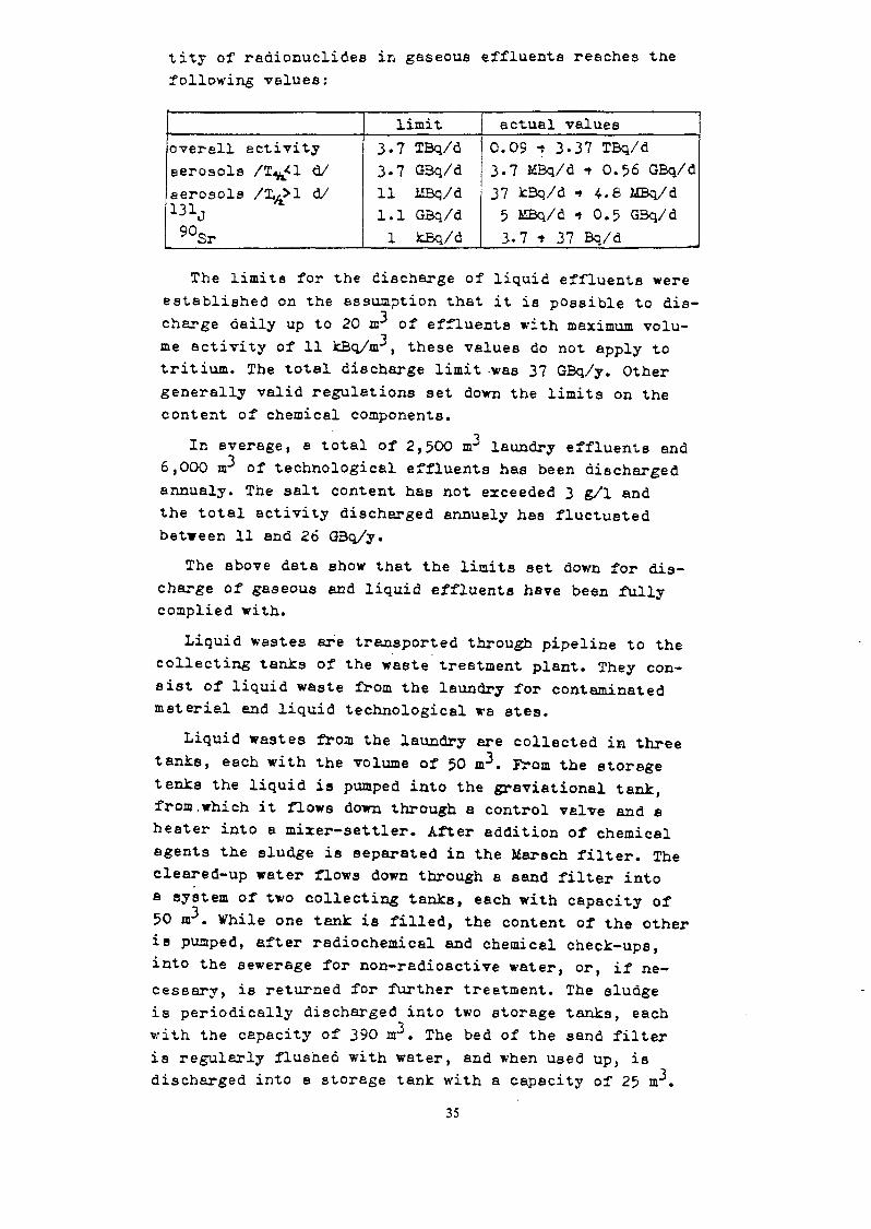
tity of radionuclides in gaseous effluents reaches tuefollowing values:
overall activityaerosols /T l d/aerosols /T,,>1 d/«lj90Sr
limit3.7 TBq/d3.7 GBq/d11 MBq/d1.1 G3q/d1 kBq/d
actuel values0.09 -t 3-37 TBq/d3.7 MBq/d t 0.56 GBq/d37 k3q/d •» 4.8 MBq/d5 MBq/d t 0.5 G3q/d3.7 t 37 Bq/d
The limits for the discharge of liquid effluents wereestablished on the assumption that it is possible to dis-charge daily up to 20 ar of effluents with maximum volu-me activity of 11 kBq/nr, these values do not apply totritium. The total discharge limit -was 37 GBq/y. Othergenerally valid regulations set down the limits on thecontent of chemical components.
In average, e total of 2,500 nr laundry effluents and6,OOO nP of technological effluents has been dischargedannualy. The salt content has not exceeded 3 g/1 andthe total activity discharged annuely has fluctuatedbetween 11 end 26 GBq/y.
The above data show that the limits set down for dis-charge of gaseous and liquid effluents have been fullycomplied with.
Liquid wastes ere transported through pipeline to thecollecting tanks of the waste treatment plant. They con-sist of liquid waste from the laundry for contaminatedmateriel and liquid technological we stes.
Liquid westes from the laundry are collected in threetanks, each with the volume of 50 m\ From the storagetenks the liquid is pumped into the graviational tank,from.which it flows down through a control valve and aheater into a mixer-settler. After addition of chemicalagents the sludge is separated in the Marsch filter. Thecleared-up water flows down through a sand filter intoa system of two collecting tanks, each with capacity of50 m3. While one tank is filled, the content of the otheris pumped, after radiochemical and chemical check-ups,into the sewerage for non-radioactive water, or, if ne-cessary, is returned for further treatment. The sludgeis periodically discharged into two storage tanks, eachwith the capacity of 390 m . The bed of the sand filteris regularly flushed with water, end when used up, isdischarged into a storage tank with a capacity of 25 m3.
35

The contaminated technological liquid wastes are' col-lected in two tanks, each with a capacity of 100 nr.From there they are pumped into a gravitational tankand flow down into a .mixer-settler. After the additionof the necessary chemicals for the coagulation of theFe?/S0./, in en alkaline medium, the sludge is separatedfrom the solution in a coagulation tank. The cleared-upwater passes through a filter bed into s feeding vessel,and through a heater into an evaporator. The evaporationis performed in an evaporator with an outside heatingsystem with an output of 2 nr/h, heated by steam at 4stm. and 180 C. After passing through the separator,the steam is fed into the condenser and the pure con-
densate is taken to two storage tanks with a capacityof 600 •a? each. The concentrate, thickened to 100 g/1,is discharged at periodical intervals into four storagetanks with a capacity of 390 nr each. The sludges fromthe coagulation tank are discharged at periodical in-tervals into two storage tanks of 390 ar each, in whichthey ere stored together with the sludges from the treat-ment of the laundry liquid wastes. The used-up beds ofthe sand filters and of the ion exchange filter are dis-charged into a storage tank with a capacity of 25 m .
The design of nuclear power plant assumed the follo-wing liquid wastes to be generated:
a. Liquid wastes from the laundry of contaminatedmaterial- highly contaminated liquid wastes 500 nr/y- very low contaminated liquid wastes 6,900 nr/y- acid liquid wastes 80 sr/y- liquid wastes from accident showers 100 nr/yT o t a l 7,580 m3/y
b. Technological liquid wastes /up to 4 GBq/sr/- liquid wastes with low salt content 3,7B3 nr/y- polluted liquid wastes 5,625 nr/y
T o t a l 9,408 nrVyThe actual quantity of liquid wastes fluctuates
between 30 and 50 nr/d in comparisson with the 25 m/dplanned. The main reason of the increased waste volumeis low content of salts. Because of the higher thanplanned volume of liquid waste, two shifts in five-daysoperation were replaced with continuous operation.
36

Concentrated liquid wastes are at presert stored inseveral storage tents. Stainless-steel-lined concretetanks of volume 390 nr are used for storage of concen-trates end sludges. The cylindrical tanks, 11.5 o indiameter end 4.2 m high, pieced in sand-lined concretetubes, are situated 2 m deep under the surface. Thet exits ere equipped with 4 level gauges, dosimeter sen-sors end ventilation system.
Recent measuring have confirmed the average volumeectivity of concentrates to be 1 t- 10 GBq/nr with thesalt content up to 10 g/1 and pH levels of 8 •» 9.
A small volume of organic liquids is generated inreactor operation, particularly oil from the turbo-compressor, which is discharged on the spot into 0.2 nrbarrels, and is stored in them in a pit in the solidwastes repository.
Solid radioactive wastes are sorted at their genera-tion point. Two vessels ere used, one for radioactivevastes, end the other for non-radioactive ones. Non-con-tamineted soft weste is teken from indoors to the rail-way sidings corridor, and after measuring it is removedas non-radioactive material and incinerated.
Radioactive soft wastes are transported into thepressing room in polyethylene bags. The bailing is per-formed 'on a Czechoslovak EL-12 press into bales with ebase 0.9 m by 0.6 m and 0.7 m high, with each bale con-taining at least 10 bags. The volume is reduced by afactor of 2 to 3. A high-lift truck leads the pressedbales onto a transport truck, which takes them to thesolid wastes repository on the power plant site. The re-pository has a total of 33 separate concrete pits of dif-ferent sizes. It is covered by e reinforced-concrete pla-te with charging openings above the different pits. Theopenings have crane-lifted lids. All pits are ventilatedinto the ventilation system of the entire repositoryfacility.
Experience has shown that storage of concentratesand sludges in underground tanks requires high invest-ment end operational costs. This is the main reason forthe turn to the solidification of concentrates and slud-ges by meens of bitumen. No serious difficulties haveresulted from the purification of gaseous effluentsand from the need to comply with the prescribed limits.
37

A very simple and unsofisticeted system for treatmentend storage of solid wastes is used with satisfactoryresults.
3. Veste Ménagement atNuclear power plant V-l is in operation for relati-
vely short period of time. Main sources of liquid was-tes are leakage of coolant, coolant purification, pu-rification of water from fuel storage, laundry of ra-dioactive material, sanitary loops and radiochemicallaboratories. An important source is decontamination,above all during refueling.
For the treatment of liquid wastes several -wastetreatment stations are used with the following arran-gement :mechanical^, evapo- mechanical cation anionfilter rator filter ~*resin -»resinfilter filterCleaned out water is either returned to the techno-
logic process or discharged into a collecting vesseland, after check-up of radioactivity, in the watercourse. Concentrate is collected in five storage ves-sels, each with capacity of 360 m .
Annual volume of concentrates and average chemicaland radiochemical compositions ere given in the follo-wing table:
totalvolume(m3/y)
1979 1980220 467
average chemicalcomposition
(g/kg)
H BO3 3Na+K+NH+Cl"NOlFepHtotalsaitcon-tent
4/80385.50.8•0.060.681.9-6.9
53.4
9/804513.81.50.120.552.01.510.1
73.3
4/813522.42.70.060.624.0-
12.2
90.0
radio-nuclide
51Cr54Mn58CO6°Co
134Cs137CS
110mAg3H
averageconcen-tration(GBq/m3)9/80
1.00.080.630.020.010.010.100.36
38

Based on the table above, the following conclusionscan be made:- an average volume of concentrates is 350 m /y. Larger
. volume in the year 1980 resulted from refueling andbeginning of the second reactor operation
- salt content in concentrates is low end it has en in-creasing trend
- specific activities of radionuclides are low in com-parisson with design
- concentration of nitrates is lower than expected.Significant part of liquid wastes treatment system
are ion exchangers. After saturation, they ere dischar-ged as radioactive wastes end stored in four vessels.Two vessels, each with the capacity of 360 m3, are de-signated for medium active ion exchangers and two vessels,each with the capacity of 145 n » for low active ones.An average increase of saturated ion exchangers was:year: 1979 volume fa?J o
1980 12.641981 /1-6/ 3.6
The results of radiochemical analyses of saturatedion exchangers end the accompanying water are given in
following table;Badionuclide
Mn-54Fe-59Co-58Co- 60Zr-95Nb-95Csrl34Cs-137Ag-llOmCr-51T o t a l
Sample No. 1/i£Ba/m3.7
4,800592
1,3691,591
5922,009
767204295-
12,119
Sample No. 2/MBq/iB3/
318240490518407
1,491_
5578
4802,877
Sample No. 1 is the ion exchanger and sample No. 2is the accompanying water. Specific activity of satura-ted ion exchangers is lower than expected, the reasonis relatively short period of operation.
39

Very high efficiency of liquid wsste treatment systemenabled also e very low level of liquid effluents dis-charged from the nuclear power plant. The total volumeend specific activities were:
Year
19791980
Volume /nr/s?
2,7104,940
Bete activity excl. 3H/kBq/v7
86130
Tritium/GBQ/s/
3 z 103
3.7 x 10³
The total volume end bete activity of liquid effluentsare several orders lower than prescribed limits, the an-nual discharge of tritium in liquid effluents is about0.1 of the limit.
Solid wastes ere stored in special concrete vessels.The following solid wastes were collected:
• 1979 - 1,000 kg of pressable wastes1980 - 3,500 Kg of pressable wastes
5 m3 of metallic wastes /metal sheet/Prevailing part of the pressable solid wastes consists
of protective aids /overshoes, gloves, aspirators/ andin a smaller extent rags and paper. Segregation of solidwastes in accordance with materiel and level of activityis not yet introduced.
Operational experience in waste management at nuclearpower plant V-l is very good. Faultless function of in-dividual components of the waste management system to-gether with a sufficient technological discipline resul-ted in relatively low production of liquid /concentratesend saturated ion exchangers/ as well as solid wastes.Further reasons ere very good state of fuel elements andlow level of contamination connected with a relativelyshort period of operation.
Several research and development works are carriedout with the aim to maintain good operational conditions.Main attention is given to the following problems:- systematic collection of data about the function of
individual components of the waste treatment system,amounts, physico-chemical and radiochemical compositionof wastes together with enelysis of these data and de-termination of basic interrelations
- improvement of decontamination methods from the pointof view of waste formation
- optimalization of waste treatment plants operation
40

- segregation of solid wastes- extraction of concentrates and ion exchangers from
storage vessels prior final ^reetment /solidification/.
4. Solidification and Disposal of WastesStorage of concentrates end solid wastes is conside-
red as a temporary solution, which is not suitable fromthe point of view of economic and long term safety. Asthe next step, incineration and baling of solid wastesand solidification of evaporator concentrates, sludgesend spent ion exchangers into low leechable mass is ac-cepted. The development end testing of suitable equip-ment ie under way, the basic part is bitumination withaqueous emulsion in a film evaporator £ 2 J • Concentra-tes are mixed with bitumen emulsion and after evapora-tion the final product is discharged into 0.2 nr drums.
Two regional repositories ere in the final stage ofdesign, one for Bohemia and Moravia and another one forSlovakia. Czechoslovak programme of waste disposal isdescribed in f 2 J • The repository is designed withtwo series of reinforced concrete double pita, eachdouble pit having the axis dimensions of length 2 x 18m, width 6 m and height 5.3 m. The bottom and sidewalls of the pits are insulated by bitumen from soakingby water. The pits are based on a gravel sand coat of30 cm, placed on a layer made from broken stone andasphalt, under which there is e layer of ntturel clayat least 50 cm thick. The filled pits are covered withstandard panels having e width of 6 a, the crevice be-tween the panels is stuffed with concrete, a waterproofinsulation of the surface is provided and the pit iscovered with 60 cm of soil.References£ 1 J fciALAEEK: E. , TITTLOVX E. :Ireatment of radioactive
wastes at the Czechoslovak Nuclear Power Station,Proc. Syzap. On-Site Management of Power ReactorWestes, OECD/IAEA, Paris /1979/, p. 185
/" 2 J MALAèEK E. : Czechoslovak policy in waste treatmentand disposal, IAEA Study Tour on Radiological Pro-tection and Waste Wane gement, Prague, September 1978
/" 3 J DLOUlrf Z. , KORTUS J. , LiALAS K E. , 1ÏAREK J. , §ELIGAM. : Disposal of low- and intermediate- level wastein the ÖSSR, Proc. Symp. Underground Disposal ofRadioactive Wastes, IAEA, Vienna /1979/
41

RETROFIT OF RADIOACTIVE WASTE CAPABILITY TO ANOPERATING NUCLEAR POWER STATIONIndian Experience
N.K. BANSAL, K. BALUWaste Management Division.Bhabha Atomic Research Centre.Trombay, Bombay,India
i ~* r- m T3 • *•» mA js o j. ri n u i
Initial years of operation ef BVifR typ*ef Tarapur Nuclear Power factor indica-ted a ne-d for a review ef radwaste scheme'originally provided because o f the largeliquid volumes generated and with a viewof decreasing the discharge to the envi-ronment. 200,000 gallon additional capa-city tanks, two in number followed by atwo stage chemical treat-sent plant ef60 K3/day capacity had to be providedabout 1 km. away from the power stationcomplex, because of the constraints ofspace and the existing support facilityin the station complex. The two stage che-mical treatment plant now operational sincelast four years hss brought down the totaldischarges f?om the station especially forCs1;>' and Co60 to a value well within the^echnical specifications of the station.The Tarapur" reactors utilising non-regene-rative déminéraliser resins for the clean upcircuits pick up very high levels of radio-activity. The original scheme had to be mo-dified to by-pass a centrifuge and pump theresin slurry directly to underground, stain-less steel lined, concrete vaults. Thechange ever has considerably reduced the aan-rem expenditure and very high radiation fieldsin the centrifuge area«, Increased volumesand the activity of the solid wastes, partf-cularly filter sludges and the incore compo-nents stored in fuel pool necessitated constru-ction of engineered containers, special shiel-ding casks and disposal facilities. The paperpresents details of these retrofit measures.
1. INTRODUCTION
The concept of retrofit of a new equipment or even anew system to an operating plant has assumed consider-able inportance in the last decade or so« Particular-ly, radwaste management has been one of the areas whereimprovements have been sought and achieved in many ofthe operating nuclear power plants in different partsof the world* A decision to go in for a retrofit ofradwaste capability may depend on different objectivesdepending on the plant and environmental conditions»
43

Broadly» the different situations warranting a retrofitnay be categorised as below:
i) variation in nature, volumes and level of acti-vity of wastes generated as plant life increases,from the original design basis;
ii) operating experience and feed back from the plantsin respect of satisfactory performance and main-tainability of radwaste process equipment;"t
iii) availability of recently developed and improvedequipment and/or process for radwaste management?
andiv) review of environmental policy in respect of allow»
able discharges of radioactivity to the enviznaent«
In this paper, I would like to share with you, someof our experiences in India in respect of retrofit-ting radwaste capability to the Tarapur Atonic PowerStation which consists of two units of BWRs (210 MWeeach) cf CEC (USA) design.
2. ORIGINAL RADWASTE SYSTEM DESCRIPTION
2.1. Liquid Wastes:Radioactivity in the liquid waste is due to activatedcorrosion products, either in suspension or solution,formed in the reactor, plus any fission products whichmay be present due to fuel leaks.The wastes are classified depending on activity, condu-ctivity, pH and detergency and collected separately sothat they can be processed and reused to the extent po-ssible. High purity (low conductivity) wastes (calleddean Radwaste) are routed to waste collector tank. Lowpurity floor (called Dirty Radwaste) drain wastes arerouted to floor drain tank régénérants and centrifugedecant water are routed to waste neutraliser tank. Laundrywastes are collected in laundry drain tank»High purity wastes are treated by filtering for the re-moval of particulate and ion exchange for the removal ofradioactive and other dissolved solids and reused byfeeding back to system. Low purity wastes having lowradioactivity are discharged to Sea after filtering toremove participates. Low purity wastes having high radio-activity levels would be evaporated and concentrated toa small volume. The filters remove particles upto 5 mic-rons in size. The laundry wastes are discharged aftersampling.
44

Figures-1 & 2 provides the schematic of the ori-ginal liquid radwaste system provided at the station.
2.2. Concentrates;The »ip^nr ^nnfT"«>«jtnre PT«» fh? crr^e^tTP-t^sthe liquid waste system, filter sludges and spention exchange resins. Concentrates are solidifiedin a cement mixer using cellulose powder as absorberend loaded in standard 200 litre drums and storedin temporary storage yard. Spent resin and filtersludges are processed through a centrifuge where thesolids are separated. The separated solids are loadedin 200 litre drums, capped and casked.
Figure-3 shows the schematic of concentrates manage-ment provided at the station.
3. PROBLEMS AND INADEQUACY
After the initial few years of operation, a numberof problems cropped up in respect of th« radwastesystem being able to cope with the demand. The pro-blems were two fold, in the sense, that both thevolume of wastes generated and the level of radioacti-vity in the wastes were on the increase.
3.1« Excessive System Leak;
The normal design load of the radwaste handling sys-tem is 50,000 litres/day for dirty radwaste and 60,000litres/day for the clean radwaste. Since station startup, it has been observed that the load on these twoare much higher than the designed values. Overand above these, with increased fuel leaks theactivity levels of the effluents were high. Thiscreated a storage problea since the discharge ofall these wastes to Sea were not possible.
3»2« Inadequacy of the concentrator;With the increased fuel leaks, many of the wastebatches had to be concentrated apart from the ré-générants. Though the concentrator is rated for aflow rate of 18 litres/mln. , it was found to beeffective for a flow rate of 12 litres/min. Thiscreated bottleneck in the neutraliser tanks whichwere needed for centrifuging as well as regenera-tion of resins .
45

3*3. Spent Resin Handling;
Major problem faced with th« solid waste handlingwas with centrifuge. Design provided only one cen-trifuge. Due to high radiation level on contact ofthe centrifuge, during a break-down, two to threedays outage will be required for rectification ofthe problem.It has been quite a difficult 3ob to process spention exchange resins as some batches of spent resinswere of 1600 R/hr. field, involving high manrea con-sumption.
3.4. Solid tfaste Disposal;In the original design of the radwaste scheme, forthe station, the provision made towards solid wastesonly included an interim storage area for concretecasks. Such a design basis is common'in many of thewestern countries where the station operations orthe utility operator has no -responsibility towardsthe final storage/disposal of the solid wastes fronthe power station; other agencies, either of thestate or private sector do exist to undertake thehandling, transport and storage/disposal of solidwastes. However, in India, as perhaps it would bein many of the developing countries, the responsi- •bility for radwaste management is centralised and itis therefore necessary to do an overall planning toinclude all aspects of radwaste management.
k. PLANNING FOR A RETROFIT
Retrofit of equipment or systems for radwaste mana-gement to an operating nuclear power station caninvolve a series of problems, some of which are listedbelow from our experience:
i) extensive decontamination efforts would beinvolved if an in-service equipment is to bereplaced. •
ii) the plant layout and size of equipment origi-nally used may not permit an effective retro-fit with improved system or even new equipment;often the improvements may have to be carriedout as an add-on system that would be built ata new location and be operated in parallel withthe old system.
46

iii) construction of the retrofit units, particularlythe laying of piping and other service connec-tions, has to reckon with the existence ofnumerous other piping, power cables andother service connections in the area ofconcern; where the existing services arealso contaminated with radioactivity, theproblem is more accute.
5. RETROFIT MEASURES ADOPTED
5.1. Augmentstion of liquid radwas te treatment:
The augmentation plant by design is a two stagetreatoent plant with a capacity to treat one hund-red thousand litres/day on a once through basis atan incoming activity level of 10-2 ci/ml» In thefirst phase, two numbers of one million litre capa-city surge storage tanks were built. The two stagetreatoent plant comprises of « chemical treataentstage by floceulation followed by ion exchange treat-ment in the second stage. Cesium is removed by copper-sulphate - pottamiua ferrocyanide treatment withferric salts used as a scavanger and the resultingfloe is separated in two batch settlers of 100 cubic•être capacity each. The cheaical sludge obtained isfurther concentrated and is disposed off as sludgefixed in sulcofloc» Following the cheaical treatment,the supernatant from the batch settler is processedthrough ft set of ion exchange columns for furtherpolishing of the waste for Cesium. The column« useTermiculite as an exchange mineral which h*s highspecificity for Cesium.The performance of this plant which has gone intooperation has been encouraging and it is expectedthat the discharges from the station into theSea will substantially reduce.
Figure-4 shows the process schematic being fol-lowed for this plant. Table-1 presents operating
5*2. Spent Resin Storage System:For the spent resin, at a specific activity levelof 7.5 me/ml., a 225 cubic metre on-site storageconcrete vault lined by 6 mm thick stainless steelhas been constructed. This would serve for about
47

5 years storage of resin arisings from both theunits of the power station. The spent resins «reproposed to be pumped in the form of slurry through.stainless steel pipes directly to the on-site stor-age. The decant liquid (once the resin pile settles)will be returned to t hs radwaste at the station forfurther treatment/ disposal. The resins would laterbe transferred to a. proposed resin fixation facility.
Figure-5 presents a schematic of the new spent resinstorage system.
5.3. Solid Vaste Storage/Disposal System;
Taking into account the volume of different cate-gories of solid and solidified wastes produced atthe power station in the initial few years of opera-tion a solid waste storage facility was constructedat site. This facility is essentiallya shallow landrepository consisting of reinforced concrete trencheswhich are about 2.5 metres deep and steel lined con-crete "Tile Holes" which are about 5 metres deep,below ground. Figures-6 & 7 show a view of thesetwo different engineered repositories.
Over the last seven years, a number of measures,as described in the paper, were taken in order toovercome the problems due to inadequate storageand absence of a suitable process for treatinghigh volumes of floor drain as well as chemicalwastes. Discharges from the station have beenbrought well below the technical specificationslaid down for the station. Providing adequatehandling and storage capacities in a shallow landrepository for solid waste, close to the powerstation, has helped in the management of solidi-fied and solid wastes from the power station.
Further efforts are underway to add certain addi-tional retrofit measures towards proper immobili-sation of spent ion exchange resins whi <h are nowheld in a large storage tank.From our experience it is felt that, despite thedesign confidence in the various systems of thepower station — which are likely to give rise toradwaste production — adequate design margin shouldbe provided while planning for the radwaste syste»attached to the power station.
48

TABLE-I
TARAPUR RADWASTE AUGMENTATION PLANT PERFORMANCE
YEAR
1976
1977
1978
1979 '
I960
WASTE RECEIVED
VOLUME (M3)
26,030
30,600
45,500
37,450
37,000
ACTIVITY
Ci
702
845
890
1190
1023
% ACTIVITY REMOVED BY TREATMENT
GROSS
70
71
87
92
91
CESIUM
• 0
82
95
96
97
FI6.-I TAPS LIQUID RADWASTE CRW SCHEMATICCLEAN UP gTSTEMDISCHARGE FROM COND.
FROM EOlDRAIN SUBLOW DO
**/\rti tkv
JIPMENT DEMINERAMP 8WN TANK I ————
V ' ' V f
WASTE COLLECTORTANKT-38
25.000 GALLEN
USED Df
e
I COILT fREACTÖR ~~
BLDG. COOLINGWATER
DCMISTER
STEAMGENERATORBLOW DOWNTANK
WASTE
COLLECTORFILTER
RADWASTEDEMINERALISER
TO FILTERSLUDGESTORAGE TANK
WASTE SAMPLETANK
T-502 5,000 GALLEN
TO DISCHARGECANAL
49

HIGH CONDUCTIVrrY WASTEFROM BLDG. SUMPS FROM WASTE COLLECTOR TANK
POST INCIDENTSYSTEMS
FROM CKEM. ADD PUMP±JL
FLOOR DRAINCOLLECTOR
TANKCHEMICALWASTE
CONDENSATEDE MINER ALtZER REAGENTS
P1G.-2 TAPS LIQUID RADWASTE DRW SCHEMATIC
TO FILTER SLUD6E STORAGE TANK
DISCHARGECANAL
MISCELLANEOUSWASTESOAP &/OftDCTEHAANTtBEARIN« WAtTt ft»OHHOT LAB.LAUMDMT PERSONALCASK DECOMTAMINATIM
r^
iCONCENTRATEDWASTE TANK .
TO SOLIDIFICATION
FIG.-3 TAPS LIQUID RADWASTE CONCENTRATES SCHEMATICRADWASTE OEMINERALIZER
DEMINERALIZERCOND.DEMINERALIZER TO ME SIN S TOR ABC TANK
TO CEKTRIFU8E
FROM F LOO» DRAM FILTER SPENT RESINPUMP
CONCENTRATORFROM FUEL
FILTER SLU08ESTORAGE TANK
FROM EVAPORATORB O T T O M ~ ~ l r
CONCENTRATEDWASTE TANK
ISULCOFLOC
RESIN FOR"SOÜDIFTCATION*
IL _ _ _ _ _ _J
ON SITE SPENTRESIN STORAGE TANK
DECANT. _ J7o~~WÂSTË~NEUTRALlZATIO«TANK
TO DRUMLOADING STATION

FIG.-4 RADWASTE AUGMENTATION SCHEMATICWASTE FROH POWER STATION
CHEMICAL CONDITIONING
TANKS
^
IXE î
'
•ST"
FIG.- 5 VIEW OF ON SiTE STORAGE TANK FOR SPENT RESIN
TO RESIN FIXATION FACILITY
t LEVEL INDICATOR 4SOO TALL
WATER LEVEL SAUCE PIPE
PUMP CHAMBER 2000 » 2000 » 1500
CONCRETE TRENCH
FLUSHING WATER LINE28 Ni S S/ 60 0.0. MOPE
DECANT PIPE 80 NB S S/60 O.P. HOPE
RESIN TRANSFER LINE40 NB S S/SO O.D. HOPE
51

FIG.6.TYPICAL CROSS SECTION OF R.C.C. TRENCH
20OV—y-^I
-ASSORTED RADIO ACTIVE WASTES
CONCRETE PRECAST SLABS
100
S.L.
CDJJ
_^
OOO*
>
>
t£*~
•
V^f
[»-W
fr.r
i
s/< •
r
4=^4
,350
i5oo .e900 £r
„ <A- ' l*Or . A. 0-
':
.
.
\
i
:
1
'
'• /: . eS"
, f e •".-t : . i - .
7100"
_^
•f ?.* ' *i- •?
y- <
rO^A.
75-
x-w'*« l
135o]
/0 00 0M K>
•V\r*DL
&^M
P X
, L t
—— - ————
————
X"~
x^X"
Aj— 15C
- DPI? P*AfiT O f f * DPUn\/ARt 1
COVER
r-R.C.C.MI50/
- —— 75 THK.P. C.C."^ - —— 250 RUBBLE SOLINO
>i.• ^— 3OO THK. MURRUN FI
t• ' f
m !i5 > — c.c (1:4.1*)I5O-iaa_,_TB
IK TLJW u V Dl A TP
WATER PROOF TILING
HUME PIPE
25 THK. SPUN CONCRETE
4-8 THK. M..S. PLATE
CEMENT CONCRETE
MUD MAT 1:4:6
3 TYPICAL 1C")
WATER PROOF TILING
TOP LAYER OF HIOH LEVELRADIOACTIVE WASTE DRUMS
BOTTOM LAYER OF HIGH LEVELRADIO ACTIVE WASTE DRUMS
RE-INFORCED CONCRETE
RUBBLE SOHNS
FIGr?

TRAITEMENT ET CONDITIONNEMENT DESEFFLUENTS ET DECHETS RADIOACTIFS DESCENTRALES NUCLEAIRES FRANÇAISES AEAU PRESSURISEE
J. CELERIElectricité de France.Direction de l'équipement,Service d'études et projets thermiques et nucléaires,Paris la Défense
P. POTTIERCEA, Centre d'études nucléaires de Cadarache,Division d'études du retraitement, déchets et
chimie appliquéeSaint-Paul-lez-Durance
Y. SOUSSELIERCEA, Centre d'études nucléaires de
Fontenay-aux-Roses,Institut de protection et sûreté nucléaire,Fontenay-aux-Roses,France
Le recherche d'un optimum en matière de traitement 'o" effluents passe nécessèi-rempit par une analyse globale -de le chaîne dont les maïllons sont le traite-ment des effluents liquides, le conditionnement des déchets ainsi produits,leur transportât leur stockage. Cette recherche doit par ailleurs être animéepar une triple préoccupation : développer des- procédés sûrs, minimiser lescoûts d'investissement et d'exploitation, réduire le volume ces déchets àstocker.
Le mémoire présentera les principal aspects techniques des traitements etconditionneaents ainsi crue ceux liés au contrSIe du confinement. Les aspectséconomiques et ceui du stockage étaient présentés dans deux autres communica-tions françaises.
ABSTRACT
The attempt to find the best method of creating effluents necessarilyinvolves s complete analysis of the entire chain of processes, including treat-ment of liquid effluents, conditioning of the waste thus produced, and thetransport and storage of this waste. Three requirements have to be kept in mind:
(1) To develop safe procedures;(2) To minimize the investment and operating costs; and(3) To reduce the volume of the waste to be stored.
53

The psper presents the principal technics! aspects of treatment,conci tior.ing and confinement concrci. The economic gspects end the details ofthe storage are covered in two other French papers.
I. INTRODUCTION
L'industrie nucléaire s'est préoccupée dès les premiersstades de son développement de la question des déchets radio-actifs. Alors qu'elle aurait pu - ce qui aurait été, jusqu'àun certain degré de développement, sans aucune conséquenceraciclogique et sans aucun effet sur l'environnement - rejetersans contrôle et sans traitement, comme l'avait souvent faitcertaines industries chimiques, elle a jugé préférable detraiter les effluents, conditionner et stocker les déchets.
Mais il n'était évidemment pas possible en choisissantcette option d'obtenir dès le départ un optimum pour l'ensemblede cette chaîne de gestion. On ne pouvait disposer dès lecommencement des procédés conduisant aux formes les plus sûres,minimisant le plus possible les valeurs à stocker, ainsi queles coûts d'investissement et d'exploitation. Pour comparerles procédés, il faut bien connaître la composition et lescaractéristiques des effluents à traiter et déchets à condi-tionner. Pour développer ces procédés et les optimiser, il fautdisposer de déchets correspondant à la production d'installationsde taille industrielle ; il faut donc disposer de réacteurs detaille commerciale en exploitation.
Il n'est cependant pas souhaitable d'attendre ce stadepour commencer le développement des procédés optimaux, ce quiobligerait de garder longtemps en fonctionnement des condition-nements moins satisfaisants. La solution à ce dilemme résidedans une collaboration étroite et active entre les exploitantsdes centrales nucléaires et les chercheurs étudiant les nouveauxprocédés. Une telle collaboration permet -à ceux-ci de' disposerde données précises sur les déchets et les résultats obtenusdans la marche des installations de traitement et de condition-nement et à ceux-là de tenir compte de l'avancement des recherchesdans les modifications à apporter aux installations, mais aussid'infléchir, le cas échéant, les programmes de recherches.
Cette collaboration doit évidemment être menée en liaisonétroite d'une part, avec les responsables du stockage, d'autrepart, avec les responsables de l'élaboration des critères desûreté. Avec les responsables du stockage, car on ne peuttraiter et conditionner des déchets sans avoir la façon dont ilsseront stockés et d'ailleurs ces responsables seront amenés àéditer des spécifications d'acceptabilité pour les colis dedéchets dont les conditionneurs devront tenir compte. Avec lesresponsables de l'élaboration des critères de sûreté, car cescritères sont évidemment à prendre en compte dans le développe-ment des procédés.
C'est en se basant sur une telle collaboration queED? et le CEA ont pu mettre au point un schéma optimal degestion des déchets des centrales électronucléaires françaisesque présente cette communication.
54

II. ETUDE DES RESULTATS ACTUELS ET ORIENTATIONS
La recherche d'un prment et de conditionnementd'une centrale à eau pressuglobale de la chaîne dont leffluents liquides, le condprocuits, leur transport etêtre animée par une tripleper des procédés sûrs, puisstocker et enfin minimiserd ' exploitation .
océdé optimum en matière de traite-des effluents et déchets radioactifsrisée (PWR) passe par une analysees maillons sont le traitement desitionnement des déchets ainsileur stockage. Cette recherche doit
préoccupation, en priorité, dévelop-réduire le volume des déchets à
les coûts d'investissement et
Il convient de rappeler qu'une centrale à eau pressuriséeproduit :
- des effluents liquides qui sont collectés, stockés,traités, contrôlés avant rejet ou réutilisation par deux cir-cuits : le traitement des effluents primaires (TÊP) et letraitement des effluents usés (TZU) .
- des déchets dits de procédé qui comprennent les filtres,résines et ccncentrats d1 évaporateurs des circuits précédentsainsi que les résines et filtres de circuits auxiliaires telsque le contrôle volumétrique et chimique (RCV) , le traitementdes eaux de piscines (PTR) et le traitement des purges desgénérateurs de vapeur (APG) en cas de fuite du circuit primairevers le circuit secondaire.
- des déchets dits technologiques constitués par deschiffons, papiers, feuilles de plastique, bois, cartons,pièces métalliques et objets divers légèrement contaminés.
Le tableau I ci-après donne une estimation des productionsannuelles de ces divers déchets pour les tranches 900 et1300 MWe.TABLEAU I . Production annuelle de déchets radioactifs
Déchets
Concentrats d' évaporateursRésines échangeuses d'ions
- faiblement actives- moyennement actives- fortement actives
Solutions de décontaminationFiltresDéchets technologiques
1 tranche900 MW25 mô9 m34 m35 m32 mô
20150 m3
1 tranche1300 MW
35 m312 m3S, 5 m37 , 5 m32, 5 m330200 m3
Ces valeurs sont confirmées par les premiers résultatsd'exploitation en ce qui concerne les tranches 900 MW.Pour le conditionnement des déchets dits de procédé, EDF aopté pour le procédé d'enrobage dans les liants hydrauliques.Ce choix a été dicté par la facilité de mise en oeuvre de ceprocédé et par des considérations économiques. L'enrobages'effectue dans une installation de traitement des effluentssolides (TES) qui est soit commune à deux tranches (palier900 MW) soit propre à une tranche (1300 MW 1ère génération P4)soit commune à 4 tranches (1300 MW 2ème génération P'4) .
Sur les tranches 900 MW l'enrobage des déchets s'effectuedans des conteneurs en béton dont les caractéristiques sontprésentées dans le tableau II ci-après. A l'intérieur de cesconteneurs le malaxage est effectué par une pale qui est soitperdable soit perdue à l'exclusion des conteneurs recevant lesfiltres qui sont remplis directement avec du béton.
55

TABLEAU II. Caractéristiques des conteneurs en béton
Type
CIc:C3C4
ß en m
! M1,1
Hauteurer. ir.
I -.Epaisseur
en CTT.
15504015
Volume utileOT. 1
950350140500
Volume ext.er. m2
\ >1,255
Les conteneurs C1, C2, C3 sont réservés à l'enrobagedes résines et concentrats, le conteneur C4 reçoit les filtres.Quant aux déchets technologiques ils sont compactés par unepresse dans des fûts métalliques de 200 1.
Alors que ces techniques étaient mises en oeuvre surles premières tranches 900 MW, EDF a engagé en étroite liaisonavec les unités de Recherche et Développement du CEA ainsiqu'avec l'ANDRA un programme d'études et d'essais en vue deminimiser les volumes de déchets à stocker ainsi que les coûtsd'exploitation tant dans les centrales que sur le centre destockage. L'effort a porté principalement sur les deux postesqui affectent le plus le volume des déchets ; c'est -à-direle traitement des effluents usés et le procédé de conditionne-ment des déchets.
Pour le premier poste cité, ont été ou sont comparésau traitement par evaporation thermique, les traitements parrésines échangeuses d'ions, par précipitation chimique et parevaporation à tirage d'air forcé. Pour le second poste l'analysea porté ou porte sur la faisabilité et l'intérêt économique :- du séchage des concentrats d'évaporateurs avant
enrobage,- d'une installation fixe d'enrobage dans des liantshydrauliques et dans des fûts métalliques de 400 1 à l'aided'un malaxeur actif continu,- d'une installation mobile utilisant le même procédéque ci-dessus,- d'un enrobage dans des résines thermodurcissablesà l'aide d'une installation aobile,- d'une évacuation en vrac ou préconditionnée des déchets,Parallèlement à ces actions des essais ont été ou vontêtre engagés en vue :- de développer de nouvelles formules d'enrobage dans desliants hydrauliques permettant de respecter les nouvelles spé-
cifications de l'ANDRA,- de qualifier les enrobés dans des résines thermo-durcissables réalisés dans les installations de la .centrale deCHOOZ ainsi qu'au BUGEY en recourant exceptionnellement à uneinstallation mobile.
56

III. TRAITEMENT DES EFFLUENTS LIQUIDES
Les effluents liquides d'une centrale ?¥R sont traitéspar deux circuits :
1) le circuit de traitement des effluents primaires (TIP)vers lequel est dirigée, pour être réutilisée, l'eau primairetritiée, non aérée et contaminée extraite du circuit primairelors des transitoires d'exploitation ou provenant des purges etfuites de certains équipements.
2) le circuit de traitement des effluents usés (TEU) quireçoit les drains résiduaires. Il s'agit d'eau tritiée , aéréeet contaminée provenant :
- des drains de traitement des effluents gazeux,- des trop-pleins des réservoirs d'effluents primaires,- des drains de tous les équipements véhiculant lefluide primaire,
- de 1'échantillonnage .de l'eau primaire.Sont aussi dirigés vers ce circuit les drains de plan-
chers , les effluents chimiques et les effluents de servitudeslorsque leur niveau d'activité est tel qu'ils ne peuvent êtrerejetés directement.
III.1 Circuit T.E.PLe circuit TEP, (cf figure 1) comporte, pour une tranche
1300 MW des paliers P4 et P'4, un réservoir de tête puis deuxlignes de traitement en parallèle équipées c'nacune :
- d'une chaîne de décontamination,- d'un dégaieur,- d'un stockage intermédiaire de grande capacité,- d'un évaporateur dont la fonction est de séparer
l'eau de l'acide borique,- de réservoirs de contrôle des condensats et des
concentrats avant leur réinjection dans le circuitprimaire par le circuit d'eau d'appoint.
Les circuits TEP des tranches PVVR 900 MW et 1300 MWen exploitation ou en construction sont tous de ce type.L'exploitation des premières tranches 900 MW n'a pas mis enrelief de difficultés particulières.
Pour les tranches 1300 MW de la 3ème génération (projetN4), la faisabilité et l'intérêt économique du regroupement desfonctions dégazage et evaporation ont été étudiés. Eu égard auxcaractéristiques des matériels présentés par les deux construc-teurs consultés, au gain économique global et à la diminutiondu nombre de composants actifs, cette solution a été retenue.Son schéma de principe est présenté sur la figure 2.
Il convient de noter que le circuit TEP ne constituequ'une très faible source de déchets puisque les concentratsne .sont évacués vers le traitement des effluents solides quesi leur niveau de contamination devient trop important pourles circuits qui doivent les véhiculer ou si la teneur en bore 10devient trop faible, événements qui tous deux ont un caractèreexceptionnel.
III.2. Circuit T.E.ULa nature même des effluents à traiter et la fonction
de décontamination que doit assurer ce circuit conduisent à •une conception plus simple que celle du TEP.
57
En effet seuls les crains résiduaires et une faiblepartie des drains de planchers présentent un niveau d'activitéqui nécessite une décontamination efficace. Pour les tranches900 MK et les premières tranches 1300 MW , la décontaminationde ces effluents est assurée par evaporation thermique. Commel'indique la figure 5, le circuit comporte :
- des réservoirs de tête,- une installation de décontamination comprenant un poste
de filtration et un évaporateur,- des réservoirs de contrôle avant rejet.Pour les autres effluents (drains de planchers, effluents
de servitudes et effluents chimiques) leur niveau d'activité esten général suffisamment faible pour qu'ils puissent être rejetésaprès filtration et contrôle. Dans le cas où le rejet directne peut être effectué, ces effluents sont aiguillés vers l'ins-tallation de décontamination de la chaine de traitement desdrains résiduaires.
A l'inverse du TEP, le circuit TEU constitue la sourcela plus importante des déchets dits de procédé. En effet lesconcentrats de 1'évaporateur TEU représentent environ 70 I deces déchets, les filtres des circuits auxiliaires nucléairesétant exclus. Afin de réduire cette production, des études etessais ont été engagés. Ils visent la définition de solutionspouvant être mises en oeuvre soit sur les tranches en exploita-tion ou en construction, soit sur les tranches en projet.
Pour les premières tranches citées, les possibilitésd'installation ne permettent d'explorer qu'une seule voie, letraitement par résines échangeuses d'ions ces drains rési-duaires .
Pour les tranches en projet, l'étude a été étendue autraitement par précipitation chimique, au traitement par evapo-ration, a tirage d'air forcé ainsi qu'au séchage des concentratsd'évaporateurs.
Les essais de traitement des drains résiduaires surrésines échangeuses d'ions effectués en laboratoire puis sur unpilote à la centrale de FESSENHEIM, ont permis de démontrer lafaisabilité et l'intérêt économique de ce procédé.
La comparaison se présente ainsi:pour 2390 m3 d'effluentstraités, la consommation de résines s'est élevée à 3,25 m3 ;ce même volume d'effluents traités par evaporation aurait produit-8 m3 de concentrats à 40 000 ppm. En considérant un coefficientd'enfutage de 0,3 pour les résines et de 0,4 pour les concentratsle facteur ce réduction de volume obtenu sur les déchets àtransporter et a stocker est 48 divisé par 5,25 = 11.
074 ~<373~Le pilote de FESSENHEIM ne comportant pas de filtre enamont du déminéralisateur, le facteur de decontamination n'étaitpas très élevé. Des essais complémentaires en laboratoire àFESSENHEIM et des mesures effectuées sur un pilote de traitementdes effluents primaires à la centrale de CHOOZ ont montré qu'avecdes filtres efficaces en amont des déminéralis.ateurs, le facteurde decontamination était supérieur à 10^.
En égard aux résultats obtenus, il a été décidé récemmentd'équiper toutes les tranches PWR d'un circuit de traitement desdrains résiduaires SUT résines échangeuses d'ions. La figure 3présente la modification apportée au TEU. Les tranches deFESSENHEIM et de 3UGEY qui seront équipées en premier permettrontde sélectionner le mode de filtration à installer en amont des
58

déminéralisateurs. En effet trois techniques seront testées :- filtre classique à cartouche de papier plissé,- filtre à précouches décolmatable,- filtre à disques gravés (VACCO) décclmatable.Les résultats de ces essais sont attendus pour l'été 1983.Pour la seconde génération des tranches PWR T 300 MW (P'i)
le séchage des concentrer« a été examiné. Il n'a pas été retenucar il est apparu que ce procédé était plus onéreux et moinsperformant en réduction de volume à stocker que le traitementsur résines échangeuses d'ions.
Autre technique de traitement étudiée pour les projets1500 MW, la précipitation chimique. Des essais effectués en labo-ratoire au CEN-Cadarache I la demande d ' EDF sur des effluentsTEU ont permis de définir des procédés et de mesurer leursperformances. D'autres procédés de précipitation vont êtreétudiés pour la centrale de CHOOZ et une installation industrielledoit y démarrer prochainement. C'est à la lumière des résultatsde cette installation qu'une décision sera prise sur l'utilisa-tion de ce procédé pour les tranches 1300 MW de la Sème géné-ration (N4), en complément ou en substitution du traitement surrésines échangeuses d'ions.
III.3. Concentration des effluents liquides par evaporation àtirage d'air lorce.Ce procédé mis au point par le CEA permet d'éviter tout
rejet liquide. Il est par ailleurs de conception et de fonc-tionnement simples. Il présente actuellement deux références :une cellule industrielle de 250 1/h de capacité d1evaporationest en fonctionnement depuis 1968 sur divers types d'effluents.On en verra le schéma de principe figure 4. Une unité indus-trielle basée sur le même principe a été réalisée et exploitéeau CEN-Grenoble. Par ailleurs des modules 1 m3/h ont été étudiéspour application aux centrales électronucléaires. [1]
Ce type d1évaporateur fonctionne à une températureproche de l'ambiante et en milieu non agressif CpH 7 à 8).L'eau évaporée et transférée au flux d'air insaturé amène àdes taux de contamination de l'air rejeté très faibles : géné-ralement < 1.10~13 Ci/m3 pour les divers émetteurs et 1 à2.10~12 Ci/m5 pour l'iode 131. On notera qu'avec une surface. 'd'evaporation de 2SO m2, un air entrant à 15°C, une hygrométrie _de 82 \, une température de réchauffage de 1'effluent de 29°C1'evaporation moyenne était de 180 1/h.
EDF s'est intéressé à cette technique dans deux perspec-tives. Tout d'abord pour les centrales implantées sur des sitesdisposant d'un débit d'eau de dilution des effluents suffisant,ce procédé pourrait remplacer 1'evaporation thermique pour autantque son coût soit inférieur et que l'activité rejetée soitacceptable. Après étude il est apparu que cette perspective nepouvait déboucher, la comparaison économique étant favorableà 1'evaporation thermique. Seconde perspective, celle de sitesà faible débit de dilution pour lesquels 1'evaporation à tiraged'air forcé peut être utilisée soit en complément de 1'evapora-tion thermique soit en substitution. Economiquement, la secondevoie s'impose mais elle ne peut être suivie que si l'activitérejetée dans l'atmosphère reste acceptable. En conséquence, àla demande d'EDF diverses campagnes portant sur des effluentsréels en provenance des centrales de FESSENEETM et du BUGEYont été effectuées à Cadarache. Elles ont permis de démontrerla fiabilité de cette technique et de confirmer les niveaux
59

inférieurs aux CMAP des rejets dans l'atmosphère. Eu égardaux résultats obtenus, EDF engage les études de réalisation d'unpilote de 1 iro/h qui sera installé à la centrale de CHINON.
CONDITIONNEMENT DES DECHETS SOLIDES
Couine indiqué précédemment, le choix d ' ED.- pour leconditionnement des déchets dits de procédé s'est perte surl'enrobage dans un liant hydraulique.
Les premières formules d'enrobage ont été mises aupoint essentiellement sur le seul critère de résistance mécaniqueà la compression de l'enrobé. Compte tenu du nouveau projet despécificationsde l'ANDRA pour les colis de déchets radioactifsenrobés dans un liant hydraulique qui prévoit, entre autres,des fractions annuelles de l'activité relâchée à ne pas dépasserpour l'activité ßy globale (hors tritium), le cobalt 60, lestrontium 90 et le césium 137, EDF a engagé avec le Service desTechniques Avancées (S.T.A) du CEA et la Société Industriellede Stockage et d'Assainissement (S.I.S.A) du groupe CEA unprogramme d'essais en vue de mettre au point des formules avan-cées d'enrobage. Les essais ont été engagés en priorité sur lesrésines échangeuses d'ions car elles présentent le plus hautniveau d'activité cobalt et éventuellement césium. L'étude menéepar le STA/CEA fait l'objet d'une communication à laquelle ilconvient de se reporter.
L'engagement même de ce programme a conduit EDF à retenirl'éventualité d'une non-qualification des enrobés de résinesdans un liant hydraulique et à prendre en conséquence des mesuresconservatoires. Ces mesures qui concernent toutes les tranches900 et 1300 MW portent sur l'accroissement des capacités destockage des résines usées et sur l'installation d'un circuitpermettant l'évacuation des résines vers une installation mobiled'enrobage pax les polymères.
IV.1. Solution mise en oeuvre sur les tranches 900 MWLa mise en oeuvre du procédé d'enrobage par liant
hydraulique sur les tranches 900 MW a conduit à une installa-tion dont le schéma est présenté sur la figure 5.
Le stockage des résines et des concentrats ainsi que lafonction enrobage sont situés dans le Bâtiment des AuxiliairesNucléaires (BAN) commun à deux tranches. La préparation descharges sèches"(pulvérulents) et du béton de blocage des filtres,ainsi que le bouchonnage définitif des conteneurs en bétons'effectue dans un Bâtiment Auxiliaire de Conditionnement (BAC)commun à quatre tranches. C'est aussi dans ce dernier bâtimentque les conteneurs sont stockés avant d'être expédiés vers lecentre de stockage et que sont stockés et compactés les déchetstechnologiques. Le malaxage des concentrats et des résiness'effectue dans des conteneurs cylindriques en béton armé àl'aide de pales perdues animées d'un seul mouvement de rotation.
Les concentrats d'évaporateurs de par leur niveaud'activité, en général inférieur au Ci/m3, sont enrobés dansdes conteneurs CI. Il en est de même pour les résines faiblementactives, (activité < ^ Ci/m3). Les conteneurs C2 peuvent recevoirdes résines jusqu'à 60 Ci/m3 et les conteneurs C3 des résinesjusqu'à 600 Ci/m3.
60

Afin de prévenir une éventuelle dégradation des conte-neurs en béton due au gonflement des enrobés, la solutiondéjà utilisée à la centrale de CHOOZ qui consiste à installerune enveloppe métallique mince à l'intérieur du conteneur estgénéralisée .
IV. 2. Solution retenue pour les tranches 1500 MWLe conditionnement des déchets sur les tranches 900 MW
décrit précédemment présente l'inconvénient de mettre en oeuvredes emballages perdus dont le prix est important. Par ailleurs,la technique de dosage des résines par pot-doseur d'environ50 1 qui est utilisée manque de souplesse puisqu'elle ne permetpas toujours, à coefficient d'enfûtage donné, d'atteindre levolume maximal de résines enfûtables eu égard à leur activité.En outre le procédé ne peut s'adapter à tous les types deconteneurs.
Toutes ces raisons ont conduit EDF a apprécier l'intérêtéconomique d'un procédé de conditionnement dans des fûts métal-liques de 400 1, mettant en oeuvre un malaxeur actif continuet des emballages de transport en acier de 5 et 15 cm d'épaisseurL'intérêt économique ayant été prouvé, une installation pilotea été réalisée dans un laboratoire d'EDF afin de qualifier le*matériels ainsi que l'ensemble du procédé. Les résultats obtenussur ce pilote ont permis de retenir ce procédé pour le traitementdes effluents solides des tranches 1300 MW. L'originalité de'cette installation qui est présentée sur la figure 6 résided'une part dans un concentrateur-doseur qui permet le dosage encontinu des résines avec une teneur en eau presque constante,d'autre part dans un malaxeur continu simple, peu encombrantet d'un faible prix de revient.
IV.3. Autres procédés étudiés ou envisagésL'utilisation à l'étranger d'installations mobiles de
conditionnement des déchets a conduit EDF à examiner l'intérêtéconomique d'une telle solution et à comparer pour des tranches1300 MW une installation, fixe de conditionnement commune àquatre tranches et une unité mobile pouvant desservir huit tran-ches. Dans les deux cas le procédé de conditionnement retenu estl'enrobage dans un liant hydraulique.
Si l'installation mobile permet, et c'est une évidence,de réduire les investissements, par contre, en coût totalactualisé, l'écart par rapport à une installation fixe n'estpas significatif. Globalement néanmoins cette solution qui estprésentée sur la figure 7, est intéressante et son adoptionpour des projets futurs pourrait être envisagée à conditionque les enrobés de résines usées dans un liant hydrauliquesoient qualifiés et que par ailleurs le procédé d'évacuationdes déchets en vrac ou préconditionnés dont il sera fait mentionultérieurement ne puisse être adopté.
Autre procédé dont l'intérêt économique a été apprécié :le conditionnement des résines usées à l'aide d'une installationmobile d'enrobage dans des polymères. Si son coût est comparableà celui du procédé mis en oeuvre sur les tranches 900 MWe,il est par contre plus élevé que celui du procédé développésur les premières tranches 1300 MWe. Il n'en demeure pas moins-qu'au cas où l'enrobage de résines usées dans un liant hydrau-lique ne serait pas retenu, cette technique, sous réservé d'uneconfirmation de son aptitude a la rétention des radioéléments,est la seule qui puisse rapidement en prendre le relais.
61

L'évacuation des déchets en vrac ou préconditionnés estle procédé qui recueille la faveur d ' EDF car il présente desavantages importants par rapport aux autres procédés cités :
- éréduction des volumes de déchets transportés entreles centrales et le centre de stockage,
- adaptation du traitement des déchets à leur natureet à leur activité ; c'est ainsi par exemple que pour des déchetscontaminés par des produits de corrosion le stockage de décrois-sance pourrait se substituer à l'enrobage et au stockage défini-tif,
- prise en compte plus rapide et plus facile ces progrèstechniques effectués dans les procédés de conditionnement,
- économie en investissements et en dépenses d'exploi-tation apportée par la centralisation du conditionnement,
- assurance d'une meilleure qualité des enrobés par uneplus grande spécialisation de la main d'oeuvre et un contrôlede qualité plus constant du fait de la centralisation.
Une étude préliminaire effectuée en 1979 par lasociété PEC , à la demande d ' EDF , avait permis de démontrerl'intérêt économique de ce procédé et de proposer des solutionstechniques pour le transport des déchets et leur conditionnement.En accord avec le CEA ce projet va être prochainement repris etapprofondi.
IV . 4 . Enrobage par les polymères thermodurcissablesLe procédé mis au point par le CEA au CEN-Grenoble [2] [3]
a été développé par la réalisation d'un pilote industriel qui aère implanté" sur le site PVTR de CHOOZ (SÊNA) . Ce pilote, cons-truit et mis au point avec la participation d'EDF, du CEA et dela CCE, permet l'immobilisation des concentrais d ' évaporateurs ,des échangeurs d'ions usés et des cartouches de filtre.
On verra figure 8, le schéma de principe de.s opérations :les concentrais sont prétraités pour insolubiliser les principauxradionucléides (Cs, Sr , Co) ; puis ils sont sèches (H?0 < 6 s«)et transformés en poudre qui est dosée dans une cuve 2e pré-mélange avec l'enrobant (esters ->• charges). Le malaxage avecles agents de polymérisation (catalyseur, accélérateur ...)s'effectue dans le fût métallique de stockage. La gélificationa lieu en 5 à 4 heures, le durcissement en 24-48 heures, lemaximum de dureté est obtenu en 7 à 1 0 jours. Le rapport pondéralpoudre/enrobant est d'environ 45/55. Les résines échangeusesd'ions, transférées hydrauliquement , sont prétraitées parsaturation des sites cationiques par de la soude à pH 13.Les échangeurs d'ions sont dosés par fraction de 100 l er. fût. métal-lique 212 1,1 'excès d'eau est drainé avant malaxage avec l'enrobantet les agents de polymérisation. Le rapport volumique échangeursd'ions enrobant est d'environ 50/50.
L'installation de CHOOZ a été mise en actif en janvier1981. Le procédé de base utilise un enrobant polyester-polystyrènedont la vitesse de polymérisation est contrôlée pour éviter quela température dépasse 100°. Cette installation est prévue pourutiliser également les époxydes comme enrobant. Une étude prenanten compte les aspects techniques, économiques, les risquesinhérents au procédé, les qualités de confinement est en cours ;elle pourrait conclure, malgré le coût plus élevé des époxydes,a un intérêt plus grand pour cette matrice.
Une station mobile utilisant l'enrobage par les polyestersa été mise en oeuvre au BUGEY en 1980 et à DAMPIERRE en 1981 où,sur chaque site, une dizaine de m3 d1 échangeurs d'ions ont étéimmobilisés. Ces opérations ont été décidées dans l'attente de
62

la mise au point d'une formulation définitive d'enrobage par lesliants hydrauliques ainsi que pour disposer d'éléments technico-économiques sur une technologie alternative. On verra figure 9le schéma du type de conteneur utilisé ; 180 à 200 conteneursont ainsi été réalisés. L'activité des échangeurs d'ions estcomprise entre quelques Ci/m3 (circuit secondaire) et 300 à500 Ci/m3 (circuit primaire). Cette activité est principalementdue au ^<£-^Oco ; l'activité du ''-'•Cs varie en fonction dos ruptu-res de gaines.
IV.5. Enrobage par le bitumeEn 1980 et 1981 une installation déplaçable d'enrobage
par le bitume a été mise en action sur le site HWR de BRENNILIS.500 à 600 fûts de 200 1 de concentrats d'evaporation contenantdes nitrates, phosphates ... ont été repris et les liquidesrésultant conditionnés par bitumage au moyen d'un appareil LUWAd'une capacité d'evaporation de 50 1/h. Cette opération quirésorbait un stockage d'une dizaine d'années a permis outrela démonstration de sa faisabilité l'acquisition de donnéessur la sûreté de l'enrobage
V. CARACTERISATION DES DECHETS SOLIDIFIES
L'ANDRA (Agence Nationale pour la Gestion des DéchetsRadioactifs), après sa création en novembre 1979, a mis aupoint un cahier des charges plus complet que le cahier initialallant jusqu'à la définition des colis normalisés agréés. Demême, l'ANDRA, pour préparer les bases des futures spécifications[7] concernant le stockage au CSM;: a lancé avec le CEA et EDFdes opérations de caractérisation, en particulier pour les déchetstransférés au CSM" et, ä court terme, sur les futurs types dedéchets solidifiés qui seront produits par EDF.
V.l. Concentrats d'évaporateurs borates enrobés Par un lianthydraulique"
Lorsque le programme de caractérisation a été lancé(1979) seule la centrale de CHOOZ (SENA) produisait des concen-trats d'evaporation actifs. Ceux-ci étaient solidifiés au moyend'un liant hydraulique. Pour 200 1 d'enrobés les proportions'utilisées étaient : concentrais 80 1,chaux 12 kg, sable ~ 130 kg,ciment Portland ~ 210 kg.
Un bloc d'enrobé "vraie grandeur" a été préparé dansles conditions industrielles réelles (malaxage en fût). Le fûtmétallique a été éliminé mécaniquement et le bloc d'enrobéa été soumis à une lixiviation dynamique avec de l'eau du CEN-SACLAY. L'eau a été renouvelée avec des fréquences décroissantesde 14 à ISO jours [6] . L'activité spécifique initiale desradioéléments contenus était la suivante (x.10~3 Ci/mô) :54Mn : 35 - 58Co : 4 - 60C o : 41 - 90Sr : 59 - 1->4CS : 45 -IS'cs : 6. Après environ 2 ans, le bloc présente toujours unaspect monolithique sans autre modification qu'une possiblecarbonatation en surface. On verra, figure 10 , la fractiond'activité relâchée pour les principaux radioéléments et pourles ions sodium. On a comparé avec les résultats enregistréssur un autre enrobé obtenu avec des concentrats d'évaporateursà base XaNG5. L'enrobé PWR montre un relâchement environ deux foisplus faible des alcalins C^'Cs, Na) mais surtout un relâchement >
"CSM : Centre de Stockage de la Manche.
63

dix fois plus faible du strontium. Un programme complémentairesur la nouvelle formulation qui sera retenue par EDF est encours ce lancement. Ce programme comprend : essais de chuteet tenue au feu (risques d'entreposage et de manutention, essaisavec enveloppe métallique), mesure des propriétés mécaniquessur carottes : résistance I la compression, rupture ... mesurede l'homogénéité : macrostructurale et répartition de l'activitépar sciage et carottage, mesure de la perméabilité et résistan-ce à la lixiviation en vraie grandeur.
Les essais pouvant ne pas permettre de déterminerrapidement le comportement à long terme, des essais de détermi-nation des paramètres régissant le vieillissement des enrobésdans les conditions de l'évacuation définitive sont égalemententrepris sur des enrobés de concentrats borates avec laformuiation à base de liants hydrauliques retenue par ZDF.
•V. 2 . Enrobés par les résines thermodurcissables.Un programme de caractérisation des enrobés produits
par la SENA à CHOOZ a été lancé dès la fin de la mise au pointdu pilote industriel. Les déchets enrobés sont des poudres deconcentrats , des échangeurs d'ions usés et des cartouches defiltre .
Les propriétés suivantes sont mesurées en inactif surblocs "vraie grandeur" ou sur des échantillons sciés ou carottéssur blocs :
- densité, résistance mécanique (compression), homo-généité structurale, résistance au feu et essais de chute.
Ces mesures en inactif sont totalement terminées. Lesdensités varient de 1,38 à 1,44 pour les poudres de concentrats,de 1,10 à 1 , 1 5 pour les enrobés d'échangeurs d'ions dans lepolyester (et de 0,99 a 1,05 avec les époxydes) et de 1,58 à1,68 pour les enrobés de cartouche de filtre.
L'homogénéité macrostructurale' vérifiée sur plus de50 blocs est excellente, bien que l'on ait noté quelques fissuresinternes. La résistance à la compression varie de 7 à 900 kg/cm2pour les échangeurs d'ions enrobés polyesters ou époxy. La tenueau choc montre la bonne tenue des colis (pas d'éclats fins nide poussières, aucun désenrobage), les époxydes ayant unetenue parfaite. La tenue au feu montre que les polyesters ontune résistance supérieure a celle des époxydes, mais les couchesaltérées ont une épaisseur inférieure à 2 cm pour des feux de30 mn et la combustion ne s'entretient pas ; des pertes de poidsont été mesurées : poudres de concentrats + polyesters ou époxy :6 à 7 l, résines usées + polyesters ou époxy : 10 à 16 I. Cettedifférence est due à la vaporisation d'une partie de l'eauenrobée avec les échangeurs d'ions. Les essais de lixiviationen vraie grandeur ont démarré fin août 1981, En complément àce programme, EDF a demandé au CEA, en accord avec l'ANDRA decaractériser les colis obtenus par enrobage polyester de résineséchangeuses d'ions au moyen d'une station mobile. Le programmecomporte le contrôle de l'homogénéité de l'enrobage, des essaisde tenue au choc et au feu, des mesures de résistance à lacompression, le contrôle de la perméabilité, du point de ramol- .lissement, de la tenue à l'irradiation y (externe) et larésistance à la lixiviation (Laboratoire sur échantillon carottéet "vraie grandeur") .
De même que pour les enrobés à base de liants hydrauli-ques, le CEA prépare un programme pour étudier le vieillissementdes enrobés à base de polymères.
64

VI. CONCLUSION'
La gestion des déchets des centrales électronucléairesde la filière à eau sous pression constitue un ensemble relati-vement complexe. La -variété des effluents, de leur composition,ainsi que celle des déchets solides entraîne la possibilitéd'utiliser plusieurs schémas de gestion. Par ailleurs, de nombreuxprocédés de traitement et de conditionnement avaient été développésen France pour les différentes catégories de déchets.
Le choix initial fait pour le conditionnement des déchetsde procédé a été l'enrobage dans des liants hydrauliques. Cetteoption était bonne, mais les études faites ont permis d'améliorersensiblement les qualités des produits obtenus, de diversifierles procédés et d'obtenir ainsi dans certains cas des réductionsspectaculaires de volume, puisque elles ont pu se traduire parun facteur de réduction de 11 dans l'exemple indiqué de traitementdes drains résiduaires.
Quant à la nouvelle technique d'evaporation par tiraged'air forcé, elle pourrait même permettre de s'affranchir dans .une certaine mesure de la nécessité d'avoir des débits suffisantsd'eau de dilution.
De telles études dépassent donc nettement le seulobjectif de la gestion des déchets des centrales électronuclé-aires. C'est aussi le cas des études menées sur la caractéri-sation des déchets de réacteurs. Ces études sont destinées àfournir aux responsables du stockage et aux autorités de sûretéles éléments permettant une analyse complète de la sûreté dessites d'évacuation. Il est bien certain que les études faitesdans ce cadre, telle que diffusion des radioéléments dans lesdifférentes matrices ou formes physico-chimiques des radio-éléments relâchés, ne s'appliquent pas seulement aux déchetsde réacteurs, mais à tous les déchets de faible et moyenneactivité qui- sont produits par l'industrie nucléaire ou par l'es-utilisateurs de radioéléments.
Mais bien évidemment ces recherches sont avant toutorientées vers les objectifs essentiels de tendre vers l'optimisa-tion de la gestion des déchets des centrales, d'arriver auxprocédés les plus sûrs, d'obtenir la réduction des volumes àstocker et la diminution des coûts d'investissement et d'exploi-tation. Une collaboration étroite entre chercheurs et exploitantsa permis, comme l'a montré cette communication, d'arriver à desrésultats significatifs et représentant certainement, dans l'étatactuel des connaissances, l'optimum possible.
REFERENCES BIBLIOGRAPHIQUES
[1] J. AROD et Al."Rejet zéro en effluents liquides radioactifs. Traitementdes effluents des centrales électronucléaires à l'aide d'unévaporateur ACEREN".Colloque AIEA/OCDE-AEN, Zurich, 26.50 mars 1979, p.288
[2] G. AUBOUIN et Al."Conditionnement de déchets radioactifs par résines therroo-durcissables"Revue Générale Nucléaire, 6.12.1976, p.501-507.
65

L 3 j j ?. AU HAriAM, L. Ali"Perspectives de gestion des déchets à la Centrale Nucléairedes Ardennes"Colloque AIEA/OCDE-AEN, Zurich, 26-50 mars 1979, p. 595
m j. AROD"Conditionnement dans le bitume de déchets radioactifs. Etudesde sûreté" .Conférence on thé leachability cf radioactive solids. Gatlinburg,9-12 décembre 1980.
[S] G. BARDET"Expériences de sept années de stockage de déchets radioactifssolides de faible et moyenne activité en surface ou en tranchesbétonnées.Symposium AIEA, Vienne, 22-26 mars 1976, SM 207/39.
[6] JC. NOMINE .et Al.-"Long term leaching tests on life sized blocks of radioactivewastes".Conférence on the leachability of radioactive waste solids,Gatlinburg, 9-12 décembre 1980.
[7] L. FARCES"Les critères et les objectifs du conditionnement (prescriptionset spécifications)".Séminaire SFR?, Cadarache, 2-6 février 1981.
Fig. 1 TRAITEMENT DES EFFLUENTS PRIMAIRES (TEP)1300 M We P_?
Ellluents pnmares enceinte
E V EvaporâtesDE . DemnerabseurBA, Bâche lieservoir)DZ . Degajeu
TES . "Irailsrnent d etlluenls solidesTE G . Traitement 6 effluents gazeuxKER . Contrôle el reiel elhuents îlot nucléaire
66

Flg. 2 TRAITEMENT DES EFFLUENTS PRIMAIRES (TEP)1300 MWe N4
nCV+Ellluentsprimaires
Stockages eau dappoml
Stockages acde bonque
E V Evaporateur F : FiltreDE • Demineraliseur TES ' Traitemenl d effluents solides02 . Degazeur KER : Contrôle ei rejet effluents Hot nucléaire
Fig. 3 TRAJTEMENT DES EFFLUENTS USES (TEU)900 MWe
OE : DemmerafiseurEV : EvaporaleurBA. Bache (reservoir)
«ER • Control» el retel effluents , llol nuclaire|—~~\ Modification traitement sur résinesL._ .J echangeuses d tons i
Pompe
67

Fig.4 EVAPORATEUR A AIR PULSE ( Principe )
Plafondfiltrant
Grillefiltrante
Effluenttraiter
Concentrât
Fig. 5 CONDITIONNEMENT DES DECHETS SOLIDES (TES)9OO M We
Bâtiment auxiliaire nucléaireConcentrais •-
Rèsnes
H Château Iransteri
D
Penaoïra lillres
\l
Bâtiment auxiliaire conditionnement
y v yTrémie peseuser
(Malaxeur
Benne < Belonpulvérulents
Putverutent»
Charpement des bennesCom
Déchetslechnotogtques
î«7»B5£V;^ l \ -v '^ ' ! i : , ,^«3 j . i . .•--î- iwi
. . , - *. Presse- •-•••^"•^.Y: V
68

Fig. 6 TRAITEMENT DES EFFLUENTS SOLIDES (TES)1300 MWe
Resmes APGT £ Ui ÉDecentamnalion
^amasse-goulles «movtjte
Excès eauâac de décantationamovible
Rg.7 INSTALLATION D'ENROBAGE MOBILE (TES)1300 MWe
Concentrât»
°b
10 m3 10 34 m3 ~|
Pompe
Résine»
20 20 20
Electeur Eau
Y
Hall confine
Excel eau
Stationconditionnement
CO C°)
69

Fig 8 SOLIDIFICATION PAR LES RESINES THERMODURCISSABLES
Concentrât« Reacti f*
ln»olublll8Btlonradioéléments
Condenseur
Rétines u»»es
Ne OH —
Drainageexcès eau
Contrôleavant re)et
Additifs'polymérisation
Malaxageen fût
Poste d'enfûtage
Obturation finaleCiment
Fût métallique-loo r
Résine•¥
Polyester
Béton lourd
ConteneurBéton normalisé 9 ECHANGEURS D'IONS IMMOBILISES
DANS LE POLYESTER( Station mobile )
70

Fig.10 LIXMATION DE CONCENTRAIS PWRENROBES PAR DU CIMENT
Fraction d'activitérelâchée
2 .
Na inactlt PWR
Na inactif C E N' i
137Cs CEN
137Cs PWR
90S rCEN
2 .
.1.10-'.
5 .
60Co PWR
90Sr PWR
2 .
1 .ID-100 200 300 400 500 600
t. (jours)— i
700
71

RADIOACTIVE WASTE MANAGEMENTPRACTICES AT A LARGE CANADIANELECTRICAL UTILITY
T.J. CARTEROntario Hydro,Toronto. Ontario.Canada
ABSTRACT
Ontario Hydro, a large publicly owned electrical utilityin Canada, meets about 30% of total electrical energydemand with 4 Unit, CANDU, nuclear power stations.Because of the characteristic on-line refuelling of CANDUreactors, failed fuel can be detected and removed relativelyquickly thereby minimizing the amount of radioactivitythat is released into heat transport systems and to thewaste management systems. The high economic value ofheavy water necessitates the use of leaktight systemsand D20 recovery/recycle systems which in turn minimizethe amount of gaseous and liquid streams to the wastemanagement systems.In-station handling of radioactive gaseous, liquid andsolid wastes are based on well proven technologies widelyused in the nuclear industry. The systems for liquidand gaseous wastes tend to be less sophisticated than forLWR's while achieving comparable emissions performance.Tritium and Carbon-14 are nuclides that require specialconsideration in CANDU stations.Ontario Hydro owns and operates its own low and mediumlevel waste transportation, storage and processing facil-ities. A centralized Waste Operations Site, -serving allOntario Hydro stations, is in operation at the Bruce NuclearPower Development on the shore of Lake Huron, 250 km north-west of Toronto.A radioactive waste incinerator, in operation since 1977,has processed over 8000 m3 of waste. A compactor andbaler are used to compress the wastes which are processiblebut can not be incinerated. All wastes are placed inengineered storage facilities with nominal design lifetimesof 50 years. The various types of facilities are designedto match the hazard of the wastes to be placed in them.Some of the wastes will require ultimate disposal afterthe storage period; Ontario Hydro and Atomic Energy ofCanada Limited (AECL/CRNL) initiated a common program in1980 to develop concepts for disposal of the various wastesegments.
IntroductionOntario Hydro is a large publicly owned electric utility inCanada serving approximately 8 million customers in theProvince of Ontario. It has over 24,000 MWe of installedgenerating capacity split between hydraulic, fossil fuelsand CANDU nuclear generating stations as shown in Table 1.
73

Peak winter demand in 1980/1981 was 17,200 MWe; with anavailable reserve of 18-9%. In-service reserve was 33.7%;we target to maintain in-service reserve 25% above peakdemand .
TABLE 1Ontario's Electricity Generation Ability and
Percentage Production from Fuel Sources(I960)
Stations
hydraulic . 68
Capacity
(MW)
6400
Fossil 7 i 12600
Nuclear
Purchase
Total
4 ] 5 1 DO!
-
79
200
24300
IMW)
fc
26
52
21
1
Production
*
35
35
30
-
JOS700
(GW-h)
Although nuclear is only 21% of the installed capacity, in1980, 30% of electrical energy consumed came from thissource? nuclear stations are used for base load generation.Presently three, 4 unit nuclear stations are underconstruction. Their in-service dates, as well as two coalfired stations under construction, are shown in Table 2; by1991 Ontario Hydro will have 13,500 MWe of CANDU generation.Since the Province of Ontario has no indigenous fossilfuels, the focus for future electrical generation will behydraulic and nuclear. There is about 2,000 MWe ofundeveloped hydraulic potential left in Ontario but thisconsists of very remote sites; essentially all of the trulyfeasible large-scale hydraulic generation has been developedin Ontario. Ontario is blessed with very large reserves ofuranium and it is upon this that the electrical program inOntario in the 1990's and beyond will be built.
. • . TABLE 2Future Power Stations in Ontario 1980 - 1990
Under Construction
Type
Coal
CoalNuclear
Nuclear
Nuclear
Station
Thunder Bay
Atikokan
Pickering B
Bruce B
Darlington
Size (MW)
300
400
2000
3000
3400
In -Service Date
1981
1984- 1988
1983-1984
1983-1987
1988 - 1991
CANDU reactors use natural uranium fuel and heavy water(D20) for the moderator and coolant. There are two separatecircuits, one low pressure, low temperature moderatorcircuit and the high temperature and pressure primary heattransport circuit. In Ontario we build four unit ratherthan individual unit stations to obtain the scale andoperating economies this implies. There are two character-istics of the CANDU reactor system that result in a need forless sophisticated waste management systems then would bethe case for light water reactors (LWR). One factor is thatthe CANDU reactor system has on-line fuelling and has thecapability to detect and remove, within a matter of days,any failed fuel that might occur. Therefore, any fission,produc-t releases from failed fuel into the heat transportsystem are minimized resulting in a reduced 'source term'for the radwaste systems.
74

The other factor is that heavy water (D2°) ^-s v^ry expensiveand there has been a great deal of attention paid in theCANDU reactor design to system leak tightness. It isbecause of the economic value of the D2Û that recoverysystems and collection systems are abundant in the main andauxiliary reactor systems to recover and keep segregatedfrom light water any D20 that may escape. Since this wateris recycled rather than discarded, the 'source terms' forthe station radwaste systems are maintained as small aspossible.Therefore, because of the above two factors, CANDU reactorsystems have less need for sophisticated and extensive wastemanagement systems while still achieving emissionperformance comparable to the ALARA performance standardsthat are set for light water reactors.This paper will describe Ontario Hydro's liquid and gaseousemission control systems and performance; the solid reactoroperating waste systems and experience; and will brieflymention the common Atomic Energy of Canada Ltd. (AECL/CRNL)and Ontario Hydro project for the long term isolation ofreactor operating and maintenance wastes.
Radioactive Liquid Waste ManagementAt an Ontario Hydro four-unit CANDU station there is acentralized liquid waste management system for all fourunits. It consists of a centrally located "collectionsystem" which includes epoxy lined, concrete tanks of up to200 m^ capacity. The liquid active waste from each unitflows via segregated sump and pump systems to thesecentralized tanks. Following the collection system there isa somewhat modest "liquid radwaste treatment system". Theemphasis in maintaining segregation of waste streams is, ofcourse, to separate and minimize the volumes of any liquidradwaste that may be higher in activity than the vastmajority of the volume collected. ' This maintainssegregation of the waste stream right from the point ofproduction at a reactor unit all the way down and into theappropriate collection tank(s); any subsequent treatment inthe liquid radwaste treatment system is, thereby, morepractical and cost effective.The design basis to achieve segregation at a unit istwofold: first, on the basis of whether significant amountsof heavy water (02*3) may be present and; secondly, on thebasis of the expected levels of radioactivity to be found.Because of the economic value of H20 and the cost ofupgrading it if it were to be diluted with light water,(H2O), most systems containing heavy water (the moderatorand the primary heat transport and related auxiliarysystems) are grouped together within the reactor building orin atmosphere controlled "confinement rooms" adjacent to thereactor building. These very tight systems have associatedleakage collection systems and D20 vapour recovery driersystems. The leakage collection systems drain to sumpssegregated from the light water areas; prior to sump pumpoutthe collected liquid is analyzed for heavy water and if itcontains greater than 0.5% isotopic it is sent for cleanupand upgrading and then is placed into the D2O inventorysystem. Only if the concentration in a sump is less than0.5% D2O is the liquid then pumped to the station liquidradwaste system for eventual release. Therefore themanagement of potential liquid radwaste that may containvaluable quantities of heavy water is based upon sampleanalysis and deliberate operator action; thereby, reducing asignificant contribution to liquid radwaste emissions.
75

I Sump
To Heavy Water Clean Up System
Central Service Area (C S A )Fuelling Facility Auxiliary Areas (F F A A )
$DecayTanks
(High Activity!
^ L
v ) T . rx. 1 w.
To Immobilization System
To Sewage Treatment Plant
76

FFAAWest
Unit1
Unit2
ManagBuilding
CS A
(
Unit3
Unit4
FFAAEast
^~NVacuum \Building )
FIGURE 1Darlington GS A
Active Liquid Waste Management System
77

The liquid collection/drainage systems are called "normallyactive" and "normally inactive". The normally activesystems service all the radiological Zone 3 areas and flowto the collection tanks. Zone 3 is the highest radiologicalzone of the station and includes the reactors, irradiatedfuel bays, and all areas containing "radioactive systems".Zone 2 is a transition zone where there may be periodiccontamination due to movement of radioactive materialsthrough this area; this includes the Turbine Hall andportions of the Central Service Wing. Zone 1 is totallynonactive and is accessible to non-atomic radiationworkers. Both normally active and normally inactive drainsare located in Zone 2, while only inactive drains serviceZone 1.Figure 1 is a representative schematic of the drainagecollection and treatment system for Darlington GS A (DCS A,4 x 850 MWe) . The very important aspect of segregating thedrainage from different systems/areas on the basis ofexpected radioactivity level or chemical content is clearlyillustrated. A particular case where wast.e segregation andlocal treatment has been very effective occurs at Bruce GS A(BGS A, 4 x 750 MWe) where in one particularly large'active' sump a small filter has been installed in arecirculation loop to purify the liquid before transfer tothe collection tank. This achieves most effective andeconomic liquid waste control.Table 3 shows DGS A collection system tankage and the designannual volumes expected to arise from the various activesystems. The design intent of the liquid radwaste system isto have approximately 60 hours worth of holdup capacity inthe tanks. The liquids flowing into the active chemicalwaste tank are sampled and neutralized before transfer toother decay tanks where they can be held up for decay,treated or released.
TABLE 3Darlington GS A — Active Liquid Waste Collection System
Active Chemical Tank
Decontamination Solution Tank
Laundry Tanks
Reactor Building and ReactorAuxiliary Bay Drain Tanks
Central Service Area and FuellingFacility Auxiliary Area Drain Tanks
Decay /Treatment Tanks
Disposal Tank
No. of Tanks
1
1
2
2
3
2
1
Volume (m3).
30
10
70
200
200
200
200
Expected Waste Volume (m3/y)
4000
10
2000
12000
25000
(fraction of above)
(fraction of above)
Since Ontario Hydro stations are located on large bodies ofcold freshwater, once-through condenser cooling isemployed. Liquid radwastes below acceptable activity levelsare released in a controlled and monitored fashion via thecondenser cooling water circuit. The liquids from anisolated tank are pumped out on a batch basis after theliquid has been mixed and and analysed for gross ßy andtritium radioactivity. It is pumped out typically at15 L/sec and while being pumped an on-line activity monitorcan automatically terminate the pumpout if the level ofgross ßf activity exceeds a preset level. The ratio of CCWflow rate to pump out rate is approximately 10,000:1.
78

Because we are fortunate to have small activity arisings, wefind that we do not need to achieve as high decontaminationfactors (DF) in the liquid radwaste treatment system ascompared with the case of light water reactors. Decontami-nation factors of, say, 100 for ßy activity, which aretypical of filtration/ion exchange systems, are veryadequate; this compares with requirements for a DF of 104 to106 for some light water reactors. These higher DF ' susually require an evaporation system followed by condensatepolishing and immobilization of the evaporator bottoms. Arecent engineering evaluation for the DCS A treatment systemconfirmed once more that for Ontario Hydro a filtration/ionexchange system is the best approach for the treatment of upto 2,000 m^ of liquid per year, while maintaining acapability to treat an "upset volume" of 500 m^ once every10 years in a period of approximately two weeks. This isbased on 200 ppm dissolved solids and 50 ppm suspended.The design intent is to treat any liquids greater inactivity than 3.7 x 10⁴Bq/L (10~^MCi/ml) (excluding tritium)prior to release.As a further means of reducing the volume of liquid radwastearisings for DCS A, we have adopted a dry cleaning systemfor laundering all cotton protective clothing. This willsignificantly reduce by about 25,000 m^ per year the amountof water being released to the liquid radwaste system.Since the total ßy activity contained in all the washwaterfrom a complete water wash laundry system is less than onecurie beta/gamma per year, additional incentives foradopting this system were the ability to reclaim a greatnumber of contaminated coveralls that were not effectivelycleaned by water wash; and the reduction in demand fordemineralized water supply for the laundry system.
For. waste arising from the chemical decontamination system,capability will exist at DCS A to filter and ion exchange ifthe activity is in the range of 3.7 x 10⁵ to 3.7 x lo4 Bq/L(10~2 to 10~3 MCi/ml) and if it has acceptable chemicalcharacteristics. If the activity is in excess of 3.7 x 10⁵Bq/L (10~2^ci/ml) the capability to directly immobilize orotherwise volume reduce prior to immobilization, will exist.Because of the low volume expected per year of thisdecontamination liquid, approximately 10 m^ per year, we areinclined towards a low cost, simplified immobilizationsystem rather than a more expensive and complicated volumereduction/immobilization system. This decision will be madeby December 1981 for the Darlington system.Extensive research work is carried out at Ontario Hydro andat Atomic Energy of Canada Limited, Chalk River NuclearLaboratories on various types of volume reduction andimmobilization systems that might be applicable to the CANDUreactor operating wastes. Systems that have been evaluatedand developed include: reverse osmosis; bitumen systems,both twin-screw extruders and wiped-film evaporator systems;cement; and water extendible polyester resins. This work isongoing in Canada in support of decisions to be made fordomestic and overseas CANDU stations.Ion exchange/filtration treatment systems apply to theremoval of gross beta/gamma nuclides. These systems do notprevent the release of tritium which is a pure beta emittercharacteristic of heavy water reactor systems. Emissions oftritium via the liquid radwaste system are minimized viaattention to the design and maintenance of leak tight heavywater systems, thereby preventing the associated tritiumfrom becoming a liquid radwaste source term and occupationalexposure problem. We have portable instrumentation
79

capability to detect D2<D leaks froir. flanges, valves andvarious fittings of 10 mg/day. Spills arising fromtritiated D20 handling; the opening of systems formaintenance activities; etc, do happen, but are minimized byextensive operator training and procedures development.A further step to minimize tritium liquid emissions is via atritium removal system. A contract for a catalyticexchange/cryogenic distillation system for TRS-1 to belocated at Pickering GS A and B (PCS A/B, 8 x 520 MWe ) foruse starting in 1985 has just been awarded to SulzerCanada. The pure tritium gas which will arise from theremoval process will be immobilized as a metal tritide forstoraae. This removal will allow us to continue to meet ouremissions operating target (1% the AECB limits) fortritium as well as minimizing occupational doses.Liquid effluent performance figures for our major PickeringGS A and Bruce GS A stations are presented in Figure 2. Ourtarget is to stay at or below one percent of the annualregulatory limit and this has been achieved to date. AtPickering GS A this has been achieved without the use of theinstalled filtration/ion exchange treatment system and atBruce GS A. only the filtration portion of the treatmentsystem is in operation. Total ßy release for each stationhas ranged up to 3.7 x 10^° Bq/year (!MCi/year; PGS A) and26 x 10l° Bq/year (7^Ci/year; BGSA).
Picker'mg NGS 'A'
TRITIUMDEL - 1.4 x 10⁶ Ci per month
Water
10
2O
10-1
uj 10-3YEAR 76 77 78 79 80
Bruce NGS 'A'
TRITIUMDEL » 1.2 x 10* Ci per month
zoa i -iu0> 10-1EUlO
0 10-2.t-ztuutu io-3"• YEA
<10-3 iR '76 ' 77 ' 78 79 80
GROSS ßfrDEL - 75 Ci per month
10
ota££ 1 -
> 10-1
Uir10-3YEAR '76' 77 7B 79 80
GROSS &&•DEL • 63 Ci per month
Dzol 1-sUJO
EUJou.
K2UJul 10-3. n
—
YEAR 76 77 78 79 80
FIGURE 2Radioactive Liquid Emission Data
80

Radioactive Gaseous Waste ManagementRadioactive gaseous waste management systems in use atOntario Hydro CANDU stations (see Figure 3) are typical ofthose used in LWR stations. Air exhaust from theradiological Zone 3 areas is handled in either one of twosystems; the "contaminated" or "noncontaminated" exhaustsystem. For the Bruce and Darlington type stations thecontaminated exhaust system for each unit typically exhaustsup to 43 m3/sec of air, via duct work, from areas known tocontain sources of airborne activity. This includes themany confinement rooms located adjacent to the reactorbuilding, containing auxiliary heavy water systems. Alsoincluded is the relatively small purge flow for pressurebalance from the containment exhaust drier system. Air flowinto the confinement rooms is controlled via the exhaustsystem to minimize back flow and spread of airbornecontamination . to other parts of the station therebymaintaining good breathing air quality. The system isdesigned to assist air movement from less contaminated tomore contaminated areas.The exhaust from the contaminated ventilation system passesthrough a filtration unit consisting of a prefilter, HEPAfilter and a TEDA impregnated charcoal bed prior to stackmonitoring for particulate, 1-131 noble gas and tritium.Separatorless HEPA filters are increasingly used so thatthey can be volume reduced prior to storage as solidradwaste. HEPA filters are DOP tested twice per year andthe removal efficiency of the charcoal filters is checkedfour times per year via the use of test cannisters. Thisservice is provided to the stations by our Ontario Hydro,Central Safety Services Department.In addition, there is a noncontaminated exhaust system fromthe Zone 3 area of up to 240 ro^/sec per unit that ismonitored but not .filtered prior to release. This isexhaust air from the reactor auxiliary bay areas wherelittle contamination is found and there is no requirement tofilter to achieve our operating emission targets. The airto be exhausted from the Zone 2 area (which includes theTurbine Hall) is periodically sampled to ensure that thereis no significant activity release via this pathway.In order to reduce tritium gaseous emissions further belowcurrent performance, BGS A, BGS B and DCS A stations arehaving drier systems fitted to some confinement roomslocated outside the reactor building containment. Previouspractice has been only to dry rooms within containment. Itis expected that this will reduce station emissions oftritium as well as lowering operator doses associated withwork in the affected rooms. The installation of tritiumremoval systems in the late 1980s, similar to the concept atPCS A/B, will aid in controlling tritium airborne emissions.A central noble gas off-gas treatment system is installed ateach major station with the objective of reducing emissionsassociated with fuel failures. The system uses ambienttemperature charcoal delay beds in series with a charcoalguard bed to prevent poisoning of the main beds. Approxi-mately 35 tonnes of charcoal are used and will never need tobe replaced throughout the 40 year lifetime of the system.System flow is 22 L/s for the total station and it providesa delay of approximately 34 days before release to theenvironment. This results in a decontamination factor of 90for Xenon-133 which is the design basis for the system.
81

ooto
FIGURE 3Radioactive Gaseous Waste Management

The system installed at Pickering GS A has not beencommissioned because fuel performance and hence noble gasemissions has been excellent. The system at Bruce GS A hasbeen in operation for approximately 2 years and has broughtnoble gas emissions down by a factor of about 7 thusensuring we are achieving our performance targets. Recentimproved fuel performance at Bruce GS A may reduce the needfor continuous use of the system at that station.Carbon-14 is released via the gaseous effluent route atCAND'J stations. It is predominantly produced by neutroncapture by Oxygen-17 in the moderator system. Research anddevelopment is now underway both at Ontario Hydro and AECLto develop methods for removing this Carbon-14 frommoderator water or cover gas systems before it gets on themoderator purification resins or escapes by the cover gassystem to station exhaust. This includes the use of calciumhydroxide, barium hydroxide or bismuth oxide resulting in aproduct that can be immobilized and stored. If the decisionis made to implement a removal system, prototype applicationat our stations is one or two years away.Gaseous emission performance for Pickering GS A and Bruce GSA is shown in Figure 4. With the exception of Bruce GS A,noble gas emissions in 1977, 1978, and 1979, performance hasbeen within our operating targets. An emission standard andtarget for Carbon-14 is presently being developed.
Pickering NGS 'A'
Air
TRITIUMDEL - 2.0 x 10s Ci p«r 7 days
NOBLE GASESDEL - 4.5 x IC^frCi - M«V per 7 days
s •"-3zoi i-2UlD> 10-1£UlQ
0 10-2HUluu 10-3
**~fr•"••
\
:
stu -3zo8 1 -IUlO>io-i-£Ulo010-2.K
Uluc _ui io-3
•™". .H
MI.V
YEAR 76 77 78 79 BO YEAR 76 77 78 79 80
IODINE • 131 PARTICIPATEH DEL " 0.4 Ci P«r 7 days t- DEL • 1.0 Ci per 7 daysI 1031% 1 -IUlOui> 10-1£UlOIL0 ID'2t- lu
Ulu5 „3 nnn
YEAR 76 77 7B ' 79
5,«
._
•„ rw —
3§K i -1utOUl
£UlQ
10*2.KZUl
I .3
—
80 YEAR 76 77 78 79 BO
FIGURE 4Radioactive Gaseous Emission Data
83

Bruce NGS 'A'
ZO
oS 10'
O 10-2.
uu; 10-3.
TRITIUMDEL - 2.0 x IDS c, per 7 d»yj
YEAR 76 77 78 79 80
DELNOBLE GASES
<!.3 x lOaj-Ci MeV p.- 7 day»
76
izoV iv ' -Su<C>10l ,EUJO
O 10-2.KZUJoUJ 10-3.
— ——
!
• —— )
77 7B 79 80
IODINE -131 PARTICIPATE1- DEL| 10 ——————————_jZOg i -iUJOUJ> 10-1-cUJO
o 10-2-HZUJU
S ID'3- — — i , , ,<1D-3
—
YEAR 76 77
- 1.7 Ci p»r 7 days j- DEL - 4.3 x Ci per 7 d«y«
n
^ »W —
1izo8 i -IUJo"J> 10-1-cuDu.010-2-KZUJuUJ iD-3 <10'3 | —— Î t —— t <10'3
78 79 SO YEAR 76 77 78 79 80
FIGURE 4 (Continued)Radioactive Gaseous Emission Data
Solid Radioactive Waste ManagementOntario Hydro, unlike many utilities, operates its ownreactor waste transportation system as well as its own wastestorage site which includes systems for volume reduction,packaging and storage of waste. This Radioactive WasteOperations Site is located at Ontario Hydro's Bruce NuclearPower Development about 250 km northwest of Toronto.The following aspects of solid radioactive waste managementwill be described:1.2.3.4.5.
Characteristics of reactor operating waste.In-station collection, segregation and packaging.Transportation to the waste operation site.Centralized waste processing systems.Reactor operating waste storage principalsfacilities.
and
84

Reactor Operating Wastes CharacteristicsThe wastes are composed of a wide variety of materials andshapes. A major volume component is "nonradioactive"housekeeping wastes from areas of the station in whichradioactivity is present; this material is proceâurallytreated as "radioactive". Typical reactor wastes includediscarded protective clothing; temporary floor coveringsused for contamination control; mopheads; wood; vermiculite;water purification media such as filters and ion exchangeresins used in maintaining the quality of reactor processsystems; solidified liquid waste; discarded piping; valves;tools; and other hardware arising from the maintenance ofreactor systems.The typical annual volume and activity of waste produced atPickering GS A is summarized in Table 4. The bulk of thewaste is combustible and has very little radioactivityassociated with it. More than 99% of the radioactivity iscontained in about 5% of the total volume mainly in thewater purification media. Table 5 shows the concentrationof gross ßy , Tritium and Carbon-14 in the different wastecategories.
TABLE 4Annual Pickermg GS 'A' (4 x 500 MWe)
Solid Waste Generated(at Maturity)
Typ« of Watte
Combustible
Compactable
Non-processable
IX Resins - Disposable Can
- Bulk
Filters (Cannage)
Volumem
500
300
200
12
30
44
TotalActivity
Ci
0.3
1.0
84
1000
1300
120
Instation Collection, Segregation and PackagingThe combustible, compactable and generally the nonproces-sible categories of solid waste listed in Table 4 are allcollected in the same manner at the station. Variousconvenient "garbage collection" locations around the stationare established near rubber areas, reactor building air lockentrances and other locations, either permanent ortemporary, where waste arise. These locations have two orthree garbage cans lined with" clear polyethylene bags andeach can is labelled combustible, compactible or non-processible. In this way, segregation of the three wastetypes, so important for efficient waste processing later atthe waste operations-site, begins with the station operatorsand maintainers.
85

TABLESTypical Radioactivity Content
of CANDU Solid Reactor Wastes**
Type
Combustible
Compactible
Non-Processable
hea: TransportFilter Paniculate
Hea: Transportion Excnanoe Resir1
Mooerator IonExchange fiesm
Average Gross $7
.0006
.003
.042
*3
34
5.5
Tritium(Ci/m3)
6-
6*
6*
NOTMeasured
NV
NM
Carbon-11(CiM3)
.032 •
.032 '
.032 '
NotMeasured
3
50-210
Gamma Dose
(Rem/rt)
<.005
<.20C
<1
<60 *
OOO *
ooo ±
* Estimated Value** Prior to Volume Reductiont As measured at 30 cm from storage containers
These cans are emptied about once every shift by servicemaintainers, taken to a centralized solid waste handlingarea in the station in preparation for shipment. After agamma survey of each bag it is taped closed with anappropriate coloured tape indicating its category and isplaced in 210 L drums or 1 m3 rectilinear Type A or LowSpecific Activity (LSA) packages ready for shipment.Unusual nonprocessible waste are sometimes held up in thestation until means for handling and transporting the wastesare available. Some of the waste might have to be cut up orvolume reduced; special oversized packagings might have tobe fabricated; or modifications to existing shippingpackagings might be required in order to ship to the WasteOperations Site.For ion exchange resins we have moved away from the use ofdisposable ion exchange vessels, which are very expensive,to systems where the spent resin is slurried to centralstorage tanks in the station; typically 15 m3 to 250 m3 insize depending upon station design. In some cases the ionexchange resins are slurried into shielded resin hopperswhich are transportable within the station; the hopperscontaining spent resin are moved to a central location fordedeuteration and resin removal. In other cases, resindedeuteration and slurry removal from ion exchange columnsoccurs at these in-service locations. The resin from thecentral storage tanks is slurried into 3 m3 carbon steelcylindrical liners located within Type B overpacks forshipment to the Waste Operations Site; the resin isdewatered but not immobilized. Slurrying resin from largetanks after several years of storage can be a difficult taskdue to the tendency of the resin to harden and agglomerate;special efforts to fluidize the resin are required; this hasbeen given greater design attention in our newer stations.In-station systems keep fuel contact resins separate fromnonfuel contact, thereby allowing segregation of thedifferent resins while in storage. With the exception ofCarbon-14 in nonfuel contact resins, the hazardous lifetimeof these resins is significantly less than for fuel contactresin; the effect of Carbon-14 on the validity of thesegregation policy is being assessed.
86

Filter cartridges are used in purification systems of mainand auxiliary process systems such as primary heattransport; moderator; irradiated fuel bay; and various otherlight water (H2O) systems. At Darlington GS A we havestandardized on a thermoplastic, one micron absolute filterelement 6.7 cm diameter by 91.5 cm long. Filter elementsare used in three different configurations: single element,three element, or thirteen .element. All the filters areused in shielded transportable vessels. Once a filter isspent, the vessel is disconnected from the system and takento a central filter handling room in the station. Here thevessel is remotely opened and the spent filter removed andplaced in a "drip can" located in an off-site transportationflask. The filter vessel is refitted with new filters andmade ready for future service. The use of the drip can isto control contamination spread in the off-site flask aswell as providing centering and support for the filterassembly(s) as it is placed in the flask. While only one 13element filter assembly can fit into an off-site flask, upto 14 single element filters may fit into a properlydesigned drip can. The emphasis is on standardization ofequipment and procedures.A typical schematic of all aspects of in-station solid wastemanagement is shown in Figure 5.
TransportationOntario Hydro uses transportation packages that arecategorized according to the IAEA transportation regulationsand as licensed for use by the Canadian regulatory author-ity, the Atomic Energy Control Board. At present we use twokinds of packagings in which we may ship Type A quantities;these are 210 L (5J) drums ana 1 m^ rectilinear containers.Greater packaging and shipping efficiency are achieved withthe rectilinear packages. Most of the waste is shipped asLow Specific Activity (LSA).A Type B overpacfc is used for the shipment of in-stationflasks containing cartridge filters or disposable ionexchange columns. A newly acquired 3 m^ capacity overpackis used for the transportation of bulk dewatered resin orfor other nonroutine wastes.All of the routine reactor operating wastes from PickeringGS A (and eventually PGS B and DCS A) are transportedthrough mainly rural areas to the Bruce Nuclear PowerDevelopment for processing and storage. Since 1963, OntarioHydro has made over 2,000 waste shipments with no release ofradioactivity to the environment. Approximately fourshipments of LSA material and one shipment of Type Bmaterial are made per month from Pickering GS A to the BruceNuclear Power Development.
Centralized Waste Processing SystemsAt the Radioactive Waste Operations Site, the combustibleand compactible wastes are processed at the Waste VolumeReduction Facility (WVRF) and the non- processible waste issent directly to storage.Since 1977, the combustible waste category has been volumereduced, prior to storage/ in a batch pyrolysis type starvedair incinerator. The system consists of a primary chamber,to which 15 m3 (2,000 kg) of waste is top charged per batch,and where the waste is pyrolyzed at a temperature of 500°C. Combustion is completed in a propane firr>d afterburner
87

11
1 ——————— 1 'Purification
SysterrFitters
MiscellaneousIncmerable
Waste
In-Station ——————— i —Shielding |
H8SK !
>-o ———— \\
L.
11
Drip-Can
r
MiscellaneousCompactable
Weste
MiscellaneousNon-Processable
Waste
1
In-Stanon IrvflTransporter Packag
Afi."B
' In-Station Solid1 Waste Management1 Area1
— 1111
11111
J
Type 'B'Transportation
Flasks
1| TruCK
1r , « ;\J ^s '
n-Station Filter Handimc Roorr !_ " _ J
r
Truck
Incinerate'
BalerCompacte'
Bru« NPD WasteVolume Reduction Fee
l_
1
1
1
111
—— j —————— »»> Storage
111
-ility 1_ J
"
Spent Resinin D2O
Systems
I/SFlask
^^* "*~s
Pipeline
DjORecovery
I/SFlask
^^ \— ' In-StationWet
Storage
Type'E'Trantponation
Flask
BuRes
Cont«
kininer
Storage
Pipeline
MiscellaneousReactor
CoreComponents
Type 'B'Transportation
FlaskTruck ^
IT.—,,,,., —— r-,-1W ^^
Storage
FIGURE 5Radioactive Solid WasteManagement Flowsheet
88

chamber where volatile gases and particulate carry over areburnt off at a temperature of 900° C before they enter theflue gas treatment system. The flue gas is cooled to 200" Cby dilution with air and by an air to air heat exchanger.The flue gas is then passed through a baghouse before it isreleased to the stack.At present waste up to 0.2 mSv/h (20 mrem/h) is incineratedbut the vast majority has less than 0.05 mSv/h (5 mR/h) at30 cm. Ash from the primary chamber is unloaded by gravitydischarge into 2.5 m3 rectangular metal containersimmediately after the end of the burn cycle. An averagebatch-load of waste produces about 0.4 m3 of ash, giving anaverage gross volume reduction factor of 40:1. Specificactivity of the ash collected, ranges from 18 x 107 to 370 x107 Bq/m3 (5 to 100 mCi/m3). The net stored volumereduction factor is about 25-30:1. Contact fields on mostof the ash containers is between 0.1 to 0.2 mSv/h (10 to 20mrem/h). Emissions from the stack have been low, averaging2.2 x 10^ Bq (0.6^iCi) of gamma particulate acivity releasedper m3 of waste burned.The radwaste incinerator system is a working prototype, andas such, has had problems due to some basic designdeficiencies. Nevertheless, the operation has been rela-tively productive, accumulating over 20,000 operating hoursto date and having processed over 8,000 nt3 waste, of which2,800 m3 was burned in 1980. The process, control andequipment have been steadily modified during the course ofoperation. One of the main deficiencies has been theexcessive length of the burn cycle (40 hrs. compared todesign 24 hrs.) which limits the maximum incineration capa-city to about 3,000 m3 of waste per year. Other problemsencountered were: flue gas heat exchanger corrosion andplugging (somewhat alleviated by upstream partial airdilution cooling); failure of automatic control mode ofoperation; excessive propane consumption; and deformation ofprimary chamber inner steel liner (a portion of which hasbeen replaced with a refractory lining).Ontario Hydro is currently studying installation of a newradwaste incinerator by 1985. More incinerator capacitywill be required to be able to process all of the projectedfuture combustible waste arisings. A continuous cycle type,proven, radwaste incinerator is favoured.Ontario Hydro has used a mechanical compactor to volumereduce the compactible waste category since 1977. Thecompactor utilizes a 210 L drum as the packaging container.Waste in plastic bags is inserted into the drum and theforce ram is lowered and compresses the waste. More wasteis introduced until the drum is filled. The gross volumereduction factor achieved is approximately 4.5:1, however,due to the cylindrical drum package form, the net storedvolume reduction factor is only approximately 2.5:1. InI960, 1,025 m3 of waste with a maximum dose rate of 2 mSv/h(200 mrem/h) was compacted.To improve the storage efficiency of compacted waste, abaler was installed in May 1981. The baler utilizes arectangular compartment as the waste receptacle. A 0.4 m3cardboard box is used as a liner and acts as a container forthe vaste. After completion of the compaction process thepackage is tied with steel straps before the force ram iswithdrawn. The final package is double plastic wrapped.The baler, due to its higher platten force exerted on thewaste and its rectangular final waste package form, is a
89

more efficient mechanical compaction machine, achieving agross volume reduction factor of 7.5-9.0:1 and a net storedvolume reduction factor of 5-6:1.High force (>1,000 tonnes) supercompactors are capable ofachieving a higher volume reduction (10-15:1) and canprocess more types of waste than conventional compactors orbalers. However, supercompaction requires more developmentwork (final package form, etc.) before Ontario Hydro couldconsider it for commercial application. Supercompaction isconsidered to be a future potentially attractive volumereduction alternative for the waste presently classified asnonprocessible.
Storage Principles and FacilitiesOntario Hydro applies a conservative approach in themanagement of reactor waste. Although the practice ofdisposing such waste directly in soil at carefully selectedshallow subsurface sites appears to be acceptably safe, atthis time we have placed such materials in interim storagewith multiple confinement envelopes between the wastematerials and the subsurface environment.The principals of the program are as follows:1. All materials are stored in a retrievable manner in
facilities having a design lifetime of 50 to 100 years.2. No radioactive materials are placed directly in soil;
engineered structures are used.3. Only solids are placed in storage; liquids which are
potentially much more mobile and hence harder toisolate from the environment are first immobilised.
4. All waste placement is treated as interim storage. Acertain component of the waste stored may outlive theexpected lifetime of the storage structures and hencemay need to be retrieved and sent to ultimate disposal.
In Figure 6 the redundant confinement envelopes between thewastes and the biosphere are schematically illustrated for atypical inground structure, the concrete trench. Anencompassing till deposit whose hydrogeological character-istics have been documented by field and laboratory studiesprovides a natural confinement barrier in which lowpermeability (10~6 to 10~7 cm/s) and geochemical retardationensures that if any radioactive material were to escape fromthe structural envelope and the underdrainage system, itwould move very slowly.The other envelopes of control consist of the reinforcedconcrete envelope with provision for routine internalsampling; a granular filled interspace serviced by amonitored underdrainage system; surface drainage collectionand sampling; and groundwater sampling holes at variousdistances from the storage facilities.Direct radiation exposure of the public is prevented by thefacility's central location within the Bruce NPD site. Thewaste operations site security fence is about 1 km from theproperty site boundary which is also a limited accessperimeter. In any case the waste storage facilities aredesigned such that the dose rate at l m from fully loadedand capped facilities is less than .025 mSv/h (2.5 mrem/h).
90

3ft3?6--SÏ*^&r&*-' . '".'•'"';& ï•âmfr^m^mxmm ä
. *4i\£'«>* visi » • r IV ! * ' i ' • ' " • ' • ' • • . . ' - •" '. .* •••''.' * *' " • . * • • * ' . A. !•*""; '-.•;: • • . « . : • • • . ' . . , • • . . . • ' » ; . • . • . • • : • * • • " • ' - ' . • • . ' • • " ' •. • •m^m^:ï- '" ™**#^* ;?; ;;--——*^#&•.•••.rcv.:.-.-,-:. -?- ; ,'. Moving Ground W«tw •'••.JCh^ e'*feÜÜ- - "
FIGURESShallnu/ KilK-^llrfar«» Qtrtranp- KAitlf-inlAShallow Sub-Surface Storage: Multiple
The dose rate target at the security fence of the WasteOperation Site is less than .0025 mSv/h {0.25 mrem/h) .Ontario Hydro's design ana operating target for radioactiveemissions from the Waste Operation Site is similar to thatat our nuclear generating stations, that is 1% or less ofthe regulatory limits.The four types of storage facilities either presently in useor under construction are described below.Concrete trenches are shallow inground reinforced structuresand .they receive the processed and nonprocessible lowerlevel reactor wastes. Because of the modest radioactivitylevels much of this waste can be manually loaded. Oncompletion of loading, 0.31 m thick precast concrete lidsare sealed to the trenches using neoprene gaskets. Thetrench internal dimensions are 3 m wide X 3 m deep X 40.3 mlong and it is divided into three compartments. Trenchwalls are 0.38 m thick. The bottom of each trenchcompartment slopes to a sump and standpipe to permit waterdétection and removal.
91

Concrete tile holes are vertical tile facilities which byvirtue of their small cross sectional area minimizeradiation exposure during loading and are used for highlevels of radioactivity such as cartridge filters andpackaged ion exchange resins which have typical contactradiatio:. fields of less than 1 Sv/h (100 rem/h) . The tilehole, Figure 7, which is .69 m internal diameter by 3.5 mdeep holds two ion exchange columns or disposable filterswhich are bottom unloaded from the shielding flask to thetile hole facility. Loaded tile holes are backfilled with ahigh slump concrete to form a monolithic cylindricalstructure. Retrieval of the incased waste is based onretrieval of the one piece tile hole monolith by liftinglug's on the reinforcing steel cage or inner steel liner.The third type of storage facility, Quadricells, is an aboveground facility. Quadricells are primarily designed tocontain bulk quantities of spent ion exchange resins thatare initially collected in large in-station storage tanks.The bulk resin is transported in 3 m^ disposable steelliners in a Type B shipping flask. The flask is removedfrom the transport truck and the resin is bottom unloaded ina shielded manner into the Quadricell from the flask. TheQuadricells are also designed for a secondary role ofstoring highly radioactive reactor core components. Beingtotally above grade the Quadricells have the advantage ofbeing largely site independent; reinforced concrete beingused to provide two independent envelopes with a monitoredinterspace. Each Quadricell module, Figure 8, consists oftwo independent reinforced concrete barriers r one a cubicstructure 6 m^ by 5.5 m high that is internally separatedinto 4 cells; and four inner cylindrical concrete vesselsthat are placed within the cells. The present structureconsists of 15, 24 m^ capacity Quadricells placed in line.It covers an area about 6 m wide by 83 m long. Retrieval ofthe waste is based on lifting the 30 Mg inner concretevessel and contents. No confinement or retrieval credit iscurrently taken for the steel liner can. The Quadricell iscapable of withstanding credible earthquakes associated withthe area and is resistant to missile impacts such as smallaircraft and tornado borne utility poles. Minimum designlife is 50 years with low maintenance.The fourth type of storage structure which is now underconstruction is an above ground storage building,the LowLevel Storage Building (LLSB). The LLSB design is based ona prefabricated, prestressed concrete superstructure (Figure9). The superstructure design consists of concrete roofcolumns with 0.38 m thick concrete walls and a 0.16 mconcrete roof. The LLSB floor design is poured concretesuch that any foundation material with suitable bearingcapacity may be used. The approximate building dimensionsare 50 m long -by 30 m wide by 8 m high and can store about6,600 m^ of packaged wastes. The LLSB is designed as anunheated building, however, the design includes: a CC>2(gas) fire extinguishing system; smoke detection equipment;a forced air ventilation system; internal fixed lighting;and an internal drainage system. All radioactive wastes tobe stored in the LLSB will be pre-packaged in self-stackingmetal containers. The free standing metal containers willbe stacked to a height of 6.25 m inside the LLSB. Loadingof the wastes into the LLSB will be accomplished by a frontend loading vehicle similar to a forklift. Only wasteswhich exhibit radiation fields less than 10 mSv/h (1 rem/h)will be loaded and stored in the LLSB. To facilitate futureexpansion, the LLSB is designed as a module wherebysuccessive LLSB's can be added to existing buildings
92

Permanentng Cap
FIGURE 7Radioactive Waste Tile Hole
93

2 I D Monitoring Port •
-SI
Anchor BolU and Lifting Device (4 Per Unit) -
Plan
Slope Slope
Seal
Absorbant
Bearing Pads(4 Per Cel
FIGURE 8The Quadncel! Storagae Facility
Component vvetohts(Tons)
/ ' ~
' \•fr „-6-
———— 1= ——— ————— - ———
. _ — — _ .,_ _ _
>^ /" ~^+\°
1 / % 1
\ !\ ' ,"/
X1 Vv>y\i ^-±—-^\ - '
ti
1
11
1
11!1
ri
1
1r
• I1
:l'i i
• ii
" - /-« - i-/ "^ ', \
/ ,***"'•/ ' ,
JL ^
N\ ">
•f Irff
/ / I
t J
f Ouïe* ConcreteA
B
C
D
i
Car
Inner ConcreteCeoDewateredResinDisposableSteel ContainerInner ConcreteCylinder
12.0
60
35
1 0
16 0
SI
Gross RetrievablePackage Weight
16 + 2C + 2D + IE 33 Tons
Surnp iorMonitoringInterspace
94

utilizing a common wall and the fire protection system. Themajor advantages of the LLSB are: lower costs relative toinground trenches; more efficient land utilization; and ashorter construction lead time required to place a facilityin-service.The LLSB is designed to complement rather than to supplantthe roles of the other structures in use at the site. Theuse of the storage building for the low level waste below 10mSv/h (1 rem/h) will allow the capacity of the ingroundtrenches to be reused once the waste in this category, whichis presently stored there, is retrieved and placed in theLLSB. This plus the selective placement of some wastes fromthe tile holes (which have decayed to lower levels sinceinitial placement) into the trenches will allow the existingstorage site to provide adequate storage capacity for all ofOntario Hydro's needs until about the year 1995. The onlynew construction would be LLSE's as the need arises.At this time there is approximately 0.16 km2 of land setaside for waste operations; to date about .028 km2 has beendeveloped. The remaining area is expected to provideadequate capacity for Ontario Hydro waste operations for thenext 50 years, following present practices.The experience at the BNPD 'Waste Operation Site to date hasbeen excellent. To the end of July 1981 about 20,000 m3 oflow and medium level wastes have been received forprocessing and storage at the Waste Operation Site. Inaddition about 140 tile hole facilities have been used forthe storage of ion exchange columns and filters. Figure 10presents waste receipts by category for the last four years.There has only been a very few minor on-site contaminationincidents. Operating procedures and cleanup techniques havebeen devised in advance to minimize these occurrences and toeffectively deal with them when they do occur. None ofthese events has resulted in any public hazard. The totaloccupational dose received in operating the site has beenlow. Approximately 0.06 to 0.12 raan.Sv (6 to 12 manrem) peryear. With the advent of th-e LLSB it is expected thatincreased mechanization and material handling ease willresult in even further improvements in the successfuloperation of the site.
Reactor Wastes Isolation ProjectIn 1980 Atomic Energy of Canada Ltd., Chalk River NuclearLaboratory (AECL/CRNL) and Ontario Hydro signed an agreementto carry out a common program on long term reactor wasteisolation. This program, which does not include irradiatedfuel nor fuel wastes, is directed at matching wasteisolation and disposal concepts to various segments of thewide spectrum of reactor operating and decommissioningwastes on the basis of hazard. Options to be evaluated overthe next several years include? sanitary landfill systems?engineered near surface facilities in clay, till, shale andlimestone? intermediate depth facilities (up to, say,500 m); and deep geologic facilities similar to the Canadianconcept for fuel disposal in igneous (granite) rocks.The acquisition and development of hydrogeologic andpathways' analysis models is underway and work continues onsuch tasks as waste source term characterization;"deminimus" dose concepts? and waste packaging, handling,and immobolization techniques. This project is generic innature at the present time but the value of a more specific,focussed effort in achieving demonstrable progress isrecognized.
95

Capacity - 6600 m
FIGURE 9Perspectivp View of Low Level Storage Building

3600 —
3200 —
2800 —
5 2000.
1600 —
1200 —
800 —
400 H
Legend;•; Incinerable
Compaction
Non-Procestible
1977 1978 1979FIGURE 10
Annual Waste Receiptsat the BNPD Radioactive Waste Operations Site
1980
(IX Columns•nd Filtert)
—200
- 150
—100 £'E3
- 50
AcknowledgementsI wish to thank several members of my staff for their helpin preparing this paper: Mr. L. Krochmalnek,Mr. L. Calzoleri, Mr. K. Lo and Mr. L. Olden.
97

USDOE ACTIVITIES IN LOW-LEVELRADIOACTIVE WASTE TREATMENT
J.E. VATHOak Ridge National Laboratory.Oak Ridge. TennesseeUnited States of America
ABSTRACT
This paper describes current research, development anddémonstration (R, L&D) programs sponsored by the US Department ofEnergy ir. the area of low-level radioactive waste treatment. TheUS Department of Energy Low—Level Radioactive Waste ManagementProgram is directed toward a coordinated program covering theperiod from low-level radioactive waste generation through thedecommissioning of the disposal site. This paper addresses thetreatment portion of the program. The development efforts include:mechanical methods for metal and compactible waste.volume reduction;incineration of trash or other combustibles through the use ofcontrolled air, cyclone, or molten glass furnaces; Ultrafiltration,reverse osmosis, biological or chemical destruction of nitrates;adsorption treatment of low—concentration aqueous waste streams;combustion of organic liquids; and smelting of metal wastes toreduce their volume and conserve our natural resources.
This paper describes current research, development anddemonstrat ion ( R , D & D ) programs sponsored by the U. S. Department ofEnergy in the area of low-level radioact ive waste treatment. In theUni ted States, low-level radioactive waste inc ludes those mater ia l sthat are not removed dur ing the first cycle of spent fuel reprocessing,spent f u e l , mater ia l con ta in ing more than 10 nano curies of a lphaact iv i ty per gram, and does not result from the m i n i n g and m i l l i n g ofu ran ium ore. Thus a wide spectrum of materials including scinti l lationv i a l s , control rods, b io log ica l waste, reactor water c leanupion-exchange resin, contaminated clothing, plastic sheeting, and paperare considered to be low-level radioactive waste. The governmentsponsored R,D&D programs supplement commercial development to ensurethat the best technology w i l l be ava i l ab le to support the growth innuclear electric power generation, nuclear medic ine , research inradioactive techniques, and industr ia l applications of radioact ivematerials . The combination of a growing awareness of the necessity toprotect the environment, the desire of the pub l i c to participate inwaste disposal decisions, and the growth in the generation of low-levelradioactive waste have been ut i l ized in the overall formula t ion anddirection of these programs. The U. S. Department of Energy Low-LevelRadioac t ive Waste Management Program is directed toward a coordinatedprogram covering the period from low-level radioactive waste generationthrough the decommissioning of the disposal site. This paper addressesthe treatment portion of the program. Waste treatment has been d iv idedinto the categories of mechanical treatment, incinerat ion, chemicaltreatment, and smelting. The development efforts inc lude : mechanicalmethods for metal and compactible waste volume reduction; incinerationof medical or ins t i tu t iona l waste; incinerat ion of trash or other
99

combustibles through the use of controlled air, cyclone, or moltenglass furnaces; ultrafiltration, reverse osmosis, biological orchemical destruction of nitrates; adsorption treatment oflow-concentration aqueous waste streams; combustion of organicliquids; and smelting of metal wastes to reduce their volume andconserve our natural resources.
During the twelve month period ending September 30, 1981, 14 primeU. S. Department of Energy contractors were involved with over 40low-level radioactive waste management technology projects. Threespecific projects or task areas have been selected for discussion toillustrate new and evolving technologies and application of technologydeveloped in other waste management areas to low-level wastetreatment. The areas to be discussed include a microwave plasma torchincinerator, application of waste vitrification, and decontamination ofmetal waste by melting.
Microwave Plasma Torch Incinerator
Contaminated organic wastes are generated from numerous operationsand include solvents, greases, ion exchange resins, sludges, andlaboratory chemicals. Storage of organic waste is complicated by theirinherent ability to burn and due to the generation of gases throughradiolysis. Disposal of organic materials by shallow land burial isalso complicated by the complexant nature of many organics with theradionuclides that may be present in the waste.Because of these waste management problems, the U. S. Departmentof Energy's Rockwell Hanford Operation became interested in alternativecombustion technologies to create a better waste form for disposal.
Several significant problems encountered with ordinary flamecombustion are listed below:a. Certain chemical bonds such as the carbon-halogen bonds incarbon tetrachloride may be too stable for efficient
combustion with an ordinary flame.b. An uneven heat distribution exists in many flames with a
temperature variation ranging from 500°C to 1600°C withthe result that up to 5% or more of the.organic molecules maypass unreacted through the flame.c. An explosion hazard must always be considered for an openflame incinerator operating at atmospheric pressure.
Microwave plasma combustion solves each of the above threeproblems. Operating at 10 to 20 torr pressure with pure oxygen as theoxidizer, the plasma flame has an electronic temperature in excess of10,000° C which efficiently breaks chemical bonds and excites andionizes the gaseous atoms promoting combustion. The electronic energyis evenly distributed eliminating the different temperature zonescommon within ordinary flames. An explosion of accumulated vapors isnot possible within a plasma at the typical 10 to 20 torr pressurerange since an explosion requires the efficient transfer of energy fromone reacting molecule to another. Without the^continual input ofmicrowave energy the plasma flame will extinguish, and an ordinaryspark will not reignite the flame.Plasma combustion is considered a superior technology because ofthe high combustion efficiency, its versatility in combusting manywaste chemical forms which cannot be burned with ordinary flamecombustion, and the inherent safety of the vapor feed-stock at theselow pressures.
A first generation plasma torch was assembled by the U. S.Department of Energy's Rockwell Hanford Operation and based on a U. S.Environmental Protection Agency design for treating hazardous chemicalwaste. The equipment operates as follows: oxygen gas from compressedgas tanks is pressure regulated and fed to one branch of a mixing tee.Liquid fuel, e.g., radioactive organic liquids, is fed and vaporizedunder reduced pressure and mixed with the oxygen gas in the mixingtee. The gaseous mixture passes into a two-inch or larger diameterquartz reaction chamber where microwave radiation bombards theoxygen-fuel mixture at 10 torr pressure. The microwave power level is
100

adjusted until the entire reactor chamber volume is filled with theplasma flame. The exhaust gases are passed through a condenser wherecondensable combustion products such as water are collected and thecooled non-condensable exhaust gases a-e passed on to the vacuum pump.
Testing of the initial torch revealed that although the intenseheat generated by the torch vaporized and decomposed the organic liquidfeed at e rate of 0.5 liter per hour, only 0.01 liter per hour wasactually being oxidized. This limitation was the result of therestricted oxygen flow rate due to a relatively small vacuum pump. Asecond generation plasma torch has been operated with a larger vacuumsystem, and an increase of an order of magnitude in the fuel combustionrate has been observed.
The microwave plasma torch incinerators have burned the followingorganic chemcials at 10 torr oxygen pressure: carbon tetrachloride,acetone, methanol, ethanol, methyl-isobutyl ketone, vacuum pump oil,and benzene. The measured combustion efficiency exceeded 99.9«.Literature values for this incineration method show combustionefficiencies that exceed 99.9999%, however, the continuous on-linequadruple mass spectrometer did not possess sufficient sensitivity toconfirm this very high-combustion efficiency.
A third generation plasma torch has been designed and is beingassembled. The vacuum manifold line size has been increased to twoinches and the vacuum pump capacity increased to 8520 liters/min. As aresult of the increased oxygen throughput, the third generation torchis designed to burn over 1 liter per hour of liquid organic through asingle torch at 10 torr oxygen pressure which results in anindustrially attractive rate.
Further increases in combustion rate may be achieved by additionalincreases in the size of the vacuum equipment or by magneticcontainment of the plasma flame. It may also be achieved by manifoldingthe fuel-oxygen vapor stream into several plasma torches that areoperated in parallel.
The plasma torch components are small enough and light enough tobe hand-carried and can be'moved or installed with ease. Many othercompeting technologies offer incinerator equipment systems with weightsmeasured in tons.
An Application of Waste Vitrification
Vitrification of relatively low levels of radioactive waste mayresult in concurrent volume reduction and solidification with minimalwaste by-products. The application of this technology is an extensionof high-level waste processing development that is associated with thereprocessing of nuclear fuel. One of the low-level waste areas thatmay benefit from vitrification involves the solidification ofion-exchange resins. Many of these resins utilize an organic base andhave been somewhat difficult to solidify by mixing with cement or otherbinders.
The U. S. Department of Energy's Pacific Northwest Laboratory hasdeveloped expertise in vitrification from past and ongoing high-levelwaste programs. This experience has been combined by specialists inorganic resins and incineration to select a concept for introducingcombustible organic ion-exchange resins into the vitrificationequipment. The technique that was selected had to expose the resins tocombustion temperatures (greater than 600°C), come in contact withoxygen to support combustion, and be in contact with the glass toabsorb radioactive elements (Cs and Sr). Residence time had to beadequate to allow combustion to be completed and avoid entrainment ofcarbonaceous materials with the gaseous effluents.
Historically, two d.ifferent'processes have been developed forhigh-level waste vitrification. The joule-heated ceramic melter is onethat heats molten glass contained inside a refractory shell bydissipation of electric current in the melt with the glass productflowing into a steel canister. The second process is known as thein-can melter that melts glass directly in a stainless steel canisterwith external resistance heaters. Although .organic resin can be
101

treated in both the joule-heated ceramic melter and the in-can melter,the initial phases of the Pacific Northwest Laboratory program haveutilized the in-can melter.
Several different feed introduction techniques were evaluated butonly below glass surface entry was able to provide assured contact ofresin with the molten glass and fix the cesium and strontium in theglass product. This is merely an application of molten saltincineration concepts that have been developed for other hazardouswastes materials.
The results from the feasibility tests have opened the door to anew volume reduction process for radioactive organic resins. Theprocess avoids the ash handling and participate entrainment problems ofconventional incinerators by forcing contact of the combustibles withmolten glass. The initial combustion efficiency was so good andparticulate and radionuclide losses were so low that a recyclableparticulate filter may be able to eliminate portions of the otherwisecomplex off-gas system associated with incinerators.
However, before this process can be used on a production scale, anumber of developmental activities are required. Future activitiesmust concentrate on longer term testing with resins to determine volumereduction, processing rates, scale-up correlations, and materialconformance to processing conditions. With this information, theeconomic justification of the process can be determined.
The merits of the joule-heated ceramic melter must also beevaluated from an economic and technical standpoint. The ceramicmelter operates with a constant glass level (as opposed to the risinglevel in-can melter) so that an adjustable feed tube would not berequired. Development of the feed system and joule-heated ceramicmelter may result in improved processing rates and product quality.Glass development and product quality verification are otherdeterminations needed before the process can be put into practice.
Decontamination of Metal Waste by MeltingMelting is an attractive waste treatment for contaminated metal
scrap for several reasons. The resulting metal ingots are in theirmost dense form so that maximum volume reduction is achieved. Theshape and size of the ingots may be tailored to fit specific storagecontainers or to facilitate determination of radionuclide content.
Equipment items with simple geometry can sometimes bedecontaminated and certified as clean to the required regulatoryrelease level by direct counting and smear techniques. However, largerand more complex shapes are impossible to certify as clean to therequired level because of inaccessible spots, crevices, and cracks.
The ingot product of melting is often uniform, and thus can beaccurately tested for radionuclide content by a techrrique such aspassive gamma analysis. Melting under a slag decontaminates manymetals by concentrating the contaminants in a relatively small volumeof slag. Thus, much of the metal scrap may be moved to a lesshazardous (less costly) waste category by the combination of being ableto clean the metal by slagging and being able to determine and certifythe cleanliness level due to the homogeneity of the ingot. Some of themetal may even be sold as commercial metal scrap thus conservingnatural resources.
It has been shown on the laboratory scale at the U. S. Departmentof Energy's Oak Ridge National Laboratory that uranium and plutoniummay be routinely removed from ferrous and other materials to the 1 to 5ppm level. Obtaining the 0.1 ppm or 10 nCi/g level of plutonium insteel however, requires special care and sometimes double slagging. Ademonstration phase utilizating a six-ton capacity induction melter atthe U. S. Department of Energy's Paducah Gaseous Diffusion Plant iscurrently in progress. Approximately 100 tons of ferrous scrapcontaminated with uranium and technetium (and perhaps plutonium andneptunium in parts per billion range) will be melted under oxidizingslags and cast into one-ton ingots. These melts will determine whetherthe improved slag/metal separation in larger-sized production equipmentwill enable the 10 nano curie per gram alpha activity limit to beroutinely met in a production facility.
102

The U. S. Department of Energy's Rockwell Hanford Operation hasconducted several sets of laboratory scale melting tests that weredirected at the removal of fission products from contaminated processand heat transfer equipment. These tests explored the separation ofimpurities from stainless steel under different melting conditions andwith the use of silicate glass slags.
The exploratory melting condition that limited melt temperaturesto between 1450 and 1550°C resulted in a concentration ofradionuclioes on the upoer slag surface of the melt. Under these testconditions the slag was limited to the exposed oxide surface coating ofthe scrap metal.The explanatory melting condition that utilized a highertemperature melt (1500 to 1650°C) and electromagnetic stirringinsured that the slag portions were fragmented and distributedthroughout the molten mass. This resulted in an even distribution ofradionuclides within the ingot.
These laboratory scale melts contained five stainless steel barsin each melt. One of the bars in each melt was painted with a waterslurry of plutonium which produced a coating that contained between 0.8and 1.0 grams plutonium. Another bar in each melt had been suspendedin an acidified solution of Kanford reprocessing plant waste thatresulted in a coating that contained radioactive cobalt, cesium andeuropium.
The procedures for the glass slag decontamination melts were thesame as the high temperature melts. The glass, being less dense, wasfloated on the surface of the molten metal. Rapid electromagneticstirring of the metal was produced to allow intimate contact of themetal with the upper glass/slag phase. At the extreme high temperatureof 1600°C the reaction time of the cations with the glass wasextremely fast and complete.
Clearly, volume reduction will be achieved by melting metal scrapinto ingots of a shape and size desirable for the end dispositions ofthe metal. A 30:1 volume reduction was achieved for a batch of mixedscrap, but this will vary greatly with the original configuration ofthe scrap. The unique advantage of melting (which when combined withthe decontamination achieved, may be more important than the volumereduction) is the ability to verify accurately the radioactive nuclidecontent of the metal ingots through a combined effort of qualitycontrol, and to assure that the ingots are homogeneous, along withinspection of all ingots by passive gamma signature analysis. Once thenuclide content has been verified, the disposition of the metal dependson the cleanliness achieved and the institutional constraints.
High volume reduction factors are usually desirable for all typesof waste treatment since they are associated with lower disposal spacerequirements and costs for disposal. The reduction in volume, varieswith the waste material and the applicable treatment process. Theradionuclide concentration is increased during volume reduction, andthe higher specific activity waste products may require shieldedhandling devices and a requirement for more conservative disposalpractices. It is therefore necessary to balance treatment processselection through a systems analysis, the cost of volume reduction,disposal costs, transportation and handling requirements, and the needfor improved conditioning and packaging. It is also important toconsider the physical and chemical properties of the volume reducedwaste and the secondary wastes, such as dust filters and scrubbersolutions, in the systems analysis.
The U. S. Department of Energy program is just entering thesystems analysis phase for many of the treatment processes that areunder development. Several of the processes like ultrafiltration,controlled air incineration, biological destruction of nitrates inliquid effluents, and metal smelting of very low activity wastes havereceived considerable development and demonstration effort. Mary ofthese processes have not, however, been completely developed ordemonstrated for the higher levels of activity that may be present inpower reactor waste. DOE has therefore developed information on theexpected volume reduction and its potential impact on disposal cost,but have not developed to date the handling requirements for the
103

treatec waste, nor the maintenance of the processing equipmentassociated witn tnese higher activity wastes.
"he successful evaluation of waste treatment tecnno'ogy w i l l comewitn 'is safe, environments"1y and economically acceptaole opérât1on tosupport nuclear power generation.
104

EXPERIENCES IN THE TREATMENT OFRADIOACTIVE WASTES IN NUCLEAR POWER PLANTSIN THE FEDERAL REPUBLIC OF GERMANY
R. AMBROSRheinisch-Westfälisches Elektrizitätswerk AG,Betr. Verwaltung Biblis
H. HEPPPreussenelektra,Kernkraftwerk Würgassen
Th. F. KIENLEVereinigung Deutscher Elektrizitätswerke e.V.,Frankfurt -am-Main
D. RITTSCHERGesellschaft für Nuklear-Service,EssenFederal Republic of Germany
ABSTRACT
The liquid, gaseous and solid radioactive wastes arising fromthe operation of nuclear power plants (NPP) have - if they cannotbe reused - to be disposed of according to rules set up by thecompetent authorities. In this paper the treatment of wastes fromNPP is described as it is carried out today due to the actual lackof a waste repository in the FRG.
As most NPP have only an interim storage capacity für 1 year,-measures for a further reduction of waste arisings, for volume re-duction of the waste and for extension of the storage capacityhave become necessary.
The reduction of the waste arisings to the possible minimum isbeing achieved by administrative measures. A volume reduction ofthe waste is achieved by improvement of already existing methodsand by development of new methods. Mixed solid wastes are reducedin volume by baling at high pressure. Burnable wastes can be reducedin volume by incineration.
Liquid radioactive concentrates are reduced in volume by waterseparation, evaporation or drying. The volume reduction factorsachieved are large as compared to the formerly applied cementation.The products arising are put into cast-iron containers whichfollowing the actual knowledge, should meet the requirements forfinal disposal with respect to the pressure stability, corrosionresistance and leach resistance. Due to the high density of thecontainer material and the great wall thickness the specific acti-vity of the waste can be increased without exceeding the dose ratelimits at the outside of the containers.
105

The radioactive wastes arising in gaseous, liquid or solidform from the operation of nuclear power plants have to bedisposed of under the observance of certain given condit-ions. In the following, especially the treatment of wastesin nuclear power plants will be described, as it becamenecessary with respect to the now-a-day's situation in thefield of final disposal of radioactive wastes in the Feder-al Republic of Germany.
In a nuclear power plant with an installed electrical powerof 13OO MWe , there arises - depending on the type ofreactor - an annual quantity of approx. 85 m of liquidradioactive waste concentrates at pressurized waterreactors and approx. 200 m at boiling water reactors aswell as approx. 2OO m solid combustible and non-combust-ible mixed waste at both types of reactor.
Liquid radioactive concentrates arise from the treatmentof the liquid effluents, i.e. by evaporation, ion exchange,chemical precipitation and mechanical filtration. The applic-ation of each method depends on the degree of pollutionrespectively its specific activities [ij .
The solid combustible and non-combustible mixed waste iscomposed of, for instance, paper, used protective clothing,laboratory wastes and filter elements as well as waste frommaintenance and repair work. The proportion of combustible tonon-combustible solid waste is approx. 40-50 %. A listing of theamounts of raw waste and avarage specific activities is an-nexed hereto as table 1 .
Up to the closing of the waste disposal in the salt mineAsse II by the end of 1978, evaporator concentrates andfilter sludges were usually solidified with concrete inmobile plants. The product quality was in agreement withthe regulations for the disposal effective at that time.
In the nuclear power plants, balers had been in-stalled. The solid mixed waste had been compressed by bal-ing with a pressure of approx. 20 t directly into the obli-gatory storage drums. Volume reduction factors of about2-3 were achieved in this way. Non-compressible wastes.from repair and maintenance work had been packed into2OO 1 drums in such a manner that they could neither slideaway nor damage the inside of the drums.
106

The solidification of ion exchange resins was carried outin a mobile plant by mixing styrène and a catalyst in thewaste container |_2J (_4_i .
In order to meet the radio protection disposal conditions,parts of the treated waste had to be put additionally into400 1 drums and the free space between 200 and 400 1 drumsfilled up with concrete. Higher active components hadadditionally to be shielded by big concrete containers(3.5 tons).
Owing to the fact that nuclear power plants generallyhave waste storage capacities sufficient for one oper-ational year only, after the closing of the experimentaldisposal facility Asse, measures for the reduction of thearising waste as well as the extension of storage capaci-ties at the sites of the nuclear power plants by construct-ion of additional storage facilities had become necessary.
In order to decrease the volume of the waste, administra-tive measurements had been taken, as for example:
- replacement of paper towels by electricalhot air driers
- replacement of the usual overalls by suchfrom a more hard-wearing quality, which have,at the same time, a lower weight per unit area
- removal of packing material before enteringthe controlled area, respectively replace-ment by reutilizable and decontaminable pack-ings
- minimization of the use of washing agents
- use of washing machines with water savingprograms
- optimization of operational conditions forthe water filters in order to reduce the amountsof waste water and filter aids.
In the technical field, attempts were made to achievean optimal volume reduction of the raw waste by meansof further development of procedures already known,
107

as well as new developments. Liquid radioactive con-centrates were reduced in volume at the highest pos-sible extent by dewatering, condensation and desiccat-ion. The product achieved by this method can theneither be mixed with binder and solidified as up tonow, or it can be put into newly developed casks madefrom cast nodular iron in unsolidified condition.
The fully automatically running procedures of theresidue filter drying and the in-drum-drying for evap-oration concentrates being used at boilinq waterreactors, meet already with the above mentioned require-ments of reducing the volume to an extent as large aspossible [ej .
Eased on these procedures, new methods of volume reduct-ion for pressurized water reactors are being developed ortested, where the high contents of boron acid in the wa-tery wastes present an aggravating factor. These are:
- an improved mobile drum dryer for thecontinuous production of dry powderfrom evaporation sludges and filtersludges
- an evaporation plant for evaporatorconcentrates containing boron acid{Metaborate Procedure) [?J
In connection with the newly developed cast nodular ironcasks, drying of the boron-containing evaporator concen-trates on the basis of vacuum-destillation directly inthe cask has been tested. This procedure can also be usedfor the drying of filter residues and precipitation slud-ges as well as powdered resins and bead resins . In thenuclear power plant Biblis, another drying installationon the basis of vacuum destination for the evaporationof boron containing concentrates has been developed,tested and, up to now, been used for the volume reductionof approx. 5O m preconcentrates. Each lot of the driedproduct is filled into casks from cast nodular iron;hereby, the thickness of the walls can be adjusted in anoptimal way to the activity inventory to be drummed \_BJ .
108

Furthermore, in the nuclear power plants Biblis and Isar,the cast nodular iron containers have been used for thestorage of unfixed, dewa-cered bead resp. powdered resinsas an alternative to the former incorporation into con-crete followed by the packaging into concrete shieldings.
In order to reduce the radioactive dose commitment tothe operators, all of these operational procedures arecarried out to a high extent automatically.
A comparison of the various volume reduction procedureswith the obtainable final waste volumina is shown inpicture 1. Please find more detailed information intable 2, which is attached to this paper.
For the volume reduction of the pre-pressed mixedwaste, two procedures can be applied - combustionand baling - which can complement one another.
Combustible mixed waste can be burned and the resultingash can then be fixed with binders. The achievable volumereduction amounts to a factor of 20 - 40, depending onthe content of non-combustible waste as well as of theamount of secondary waste arising. Furthermore, in anincinerator it will be possible to burn not only solidwastes, but also combustible liquid waste, as for instanceoil and solvents.
The second procedure - high pressure compaction - can beapplied for all solid mixed waste. By increasing the press-ing power to approx. l.OOO t, compared to the so-far usedbaling with a power of approx. 20 t, a further volume re-duction of this waste can be achieved (see picture 2).The waste is filled into the pressing chamber (picture 3)and pressed into cartridge shells made from tin to slicesof 15 - 30 cm thickness (picture 4\ Waste from repairand maintenance work can be treated in the same manner.The size of these slices allows a packing into 2OO 1standard drums. This technique has been successfullyproven in the nuclear power plants Brunsbüttel, Stadeand Würgassen by use of a mobile facility.
Experiences have shown that repair waste with a highpercentage of metal parts and rubble - part of which hadalready been pre-pressed - can as well be reduced in vol-ume by a factor of 2 as precondensed waste with a highpercentage of combustible material.
109

A comparison of the achievable final waste volume is shownon picture 5. Additional information is given in table 2of the preprint.
Some kinds of waste products, for example filter cartridgesor highly contaminated components, can only be managed atlow dose commitment and costs by means of optimally adjustedpacking techniques. Thus, for the final disposal of spentfilter cartridges, a 200 1 container with a magazine forfour filter cartridges was developed.
When the residual volume has been filled with cement, the2OO 1 container can be put into a cask from cast nodulariron for the further reduction of the dose rate at the sur-face (see picture 6). The same cask can be used for each2OO 1 drum for shielding purposes (see picture 7).
In those cases in which the use of normal shielded contain-ers for the disposal of high radiation sources will not bepossible, smaller inner shielding containers have been devel-oped which can, for instance, be put into a cast nodular ironcask (see picture 8).
SUMMARY
When the procedures as outlined above will be applied con-sequently, then in the coming years a reduction of the finalwaste volume to be disposed of can be achieved at least bythe factor 2. However, this requires that the LicensingAuthorities as well as their experts accept the new proced-ures, especially those of the packing of unsolidified waste insuitable containers, and that they consider the experiencesalready obtained during the interim storage at the reactorsite when setting up the acceptance criteria for a futurefinal repository. The first licence for the packing of un-solidified waste in connection with the interim storage letassume that this technique can in principle be licensed forfinal disposal, too.
no

References1 Hepp, H. VGB-Konferenz "Kraftwerk und Umwelt 1977", 1522 Ambros, R. et al., Symposium on the On-Site Management of
Power Reactor Wastes, Zurich, 26th - 30th March Î9793 Christ, E.G., Vygen, P., ANS-Waste Management Conference,
Tulcson/Arizona, Feb. 19814 Baatz, K., "Die Entsorgung der Kernkraftwerke von radio-
aktiven Betriebsabfällen nach dem Steag-System - Betriebs-erfahrungen" VGB-Konferenz "Kraftwerkshilfseinrichtungen1978", 123
5 Ambros, R., Schroeder, H.J., VGB-Rraftwerkstechnik 59(1979), 990
6 Bindewald, H., Hepp, K., "Behandlung radioaktiver Stoffeim KKW", Atomwirtschaft 17 (1972), S. 116
7 Döllgast, W. et al., "Aufbereitung radioaktiver Abwässerzu lagerfähigen Festkörpern im KWO", Atomwirtschaft 14(1969), S. 23
8 Ambros, R., et al., VGB-Kraftwerkstechnik 61 (Novemberheft)
Comparison of disposed waste volumesattainable with different procedures
of conditioning and packagingwatery concentrate (0,6 Ci /m3)
raw waste disposed wastevolume |m3) volumes (m3)
15,010,0
"1 concrete shielding included
Picture 1
111

Picture 2

Picture 3

Picture 4

Comparison of disposed waste volumesattainable with different procedures
of conditioning and packaging
solid wasteburnable, 60% non burnable]
disposed wastevolumes (m3)
0,33
0,130,085
row wastevolume
15,010,0
öfter application of
of ter application of 100^
of ter combined pressé
Picture 5
— «>632-
7
inID
\ \
/\
«> 1050
1,0
OJ
0,01
Picture 6
' 115

«1060
Picture 7
— *632
• <S> 1060
Picture 8116

Table 1 : R A W W A S T E
type ofresidue
evaporat-or con-centratewithoutdecenteffluent
filterresidues
deconteffluents
rosi ncombust-ible solidwaste
non-com-bustiblesolid wast
solid wast
activatedcarbonwasteni 1filtercartrid-
PWR
average |Quantity i(m-Va)
i
60
10
10
2 - 3
80-100* "
a
25
2-1 D1
20 units
(1300 MWe)
contents ofsolid waste
20-30
15-30
s 10approx.30
i
. average: specifica!activity(ß jO (ci/m )
0,1-2
0,05
10
50-200
lo-2
io-2
10"< 10"Z
Bl
type ofwaste
evaporatorconcentrâtwithdeconteffluent
filterresidues,i.e. beadresin, pow-dered re-sin, fil-ter aids
._
combustibl«solidwaste '
non-com-sustiblesolid waste
solid wast<(bulkgoods)activatedwaste oil
«/R (1300 M
averagequantity
3 / v( m /s )
*20-40
200-250
;
50-150* '
50-150* •*.
10-30
33
de)
contentsDf solidvaste (SO
10-30
20-40
J
averagespecificactivity
1-10
1-10
10"3-10"2
10~3-10~2
10"3-10"2
10~/
10 -ID"5
The values for combustible and non-combustible wastes can vary to a high extent, depend-ing on the operational life of the plant and its respective operation procedures poweroperation or revision . It can be assumed that an average ratio of cumbustible to non-combustible waste is 40 60.
117

Table 2: TREATMENT OF WASTE IN THE PWR (1300 MHe)
type of resi-due
evaporatorconcentrate
filtersludges
deconteffluents
bead resin
combustiblesolid wastes
Raw wasteaveragequantitym^/a
60
10
10
2 - 3
80 - 100
averagespecificactivity(ß/3)(Ci/m
0,1 - 2
0,05
10
50 - 200
io~2
Pre-treatmentprocedure
)
drying
drying
precipit-ation,dryina
quantity(m3)
15 - 20
2 - 3
10,5
Treatment for final Disposalactivity(Ci/M3)
1 - 6
<0,5
100200
proced-ure
cementing>putting intocontainersfor finaldisposalcementing,putting intccontainersfor final
<. disposai v
putting intocontainersf. final dis-pfinQ 1cementingbinding in-to poly-styrol,putting inttdrums f. fin-al disposal
pressing20 t
" 1.000 tcombustion
factor ofvolume en-largementresp, re-duction--—
2
§ 2 +>
$ 2
1
1:3 +1 ! 6 +1 ! 25 +
type ofcontainer
200 and400 1 drumcask fromnod. iron300 - 500«- -HOcask, drumapprox.270 1" ion 1
200 1 inconcreteshielc'ino;cask drum< 200 1
200 1 drum200 1 drum200 1 drum
quantity ofcontainers(estimated)
10
4 - 6
44
40 - 60
4 - 6
135 - 17068 - 8513 - 20
ev, in corr-ing
+)relating to raw waste ++) relating to pretreated wasteto be continued

Continuation of Table 2: TREATMENT OF WASTE IN THE PWR (1300 MWe)
type of resi-due
non-combustiblewas tes
solid wastes(bulk goods)
act ivatedcarbon
waste oil
filtercartr idges
Raw waste
averagequantity
50 - 100
25
2 - 1 0
1
20 units
averagespecificactivity .(|Vj)(Ci/nT
10~3-10"2
io-2
io-2
Pre-treatmentprocedure quantity
(m3)
•
Treatment for final Disposal
activity(Ci/M3)
proced-ure
pressj ng20 t
" 1000 t
putting into contai-ners f. fial disposas
combustion
combustion
putting incontainersf. finaldisposal
factor ofvolume en-largementresp, re--duotoon— —
1 : 3 +1 : 6 +
-
1 ! 25
o
type ofcontainer
200 1 dru200 1 dru
200 1 dru
200 1 /400 1 dru
200 1 druin concr.sh ielding
quantity ofcontainers(estimated)
n 85 - 170n 43 - 85
n 125
n 1
n5
•f ) relating to raw waste;

too
C o n t i n u a t i o n of T a b l e 2 : T R E A T M E N T Of
type of resi-due
e v a p o r a t o rconcen t ra te
f i l t e r residues ( m i x t u r ef r o m bead resin, powdereresin andf i l t e r aids
combustiblesolid waste
non-combustiblesolid waste
solid wastesbulk goods
activatedcarbon
waste oil
Raw wasteaverage f averagequantity epecificm-Va t activity
j (}3/j)(Ci/m-
20 - 40
. 200 -2501
50 - 150
50 - 150
10 - 30
3
1 - 1 0
1-10
-5 _910 -10
10"3-10"2
lo'^-io"2
io-2
10~3-10~4
Pre-treatmentprocedure
)
d r y i n g
d r y i n g
quantity(n,3)
2 - 1 2
40-100
*
W A S T E IN THE BWR (1300 H U e )
Treatment for final Disposalactivity(Ci/M3)
10 - 5C
2-50
proced-ure
cemen t ingp u t t i n g in tconta inersf o r f i n a ldisposal
c e m e n t i n g
p u t t i n g in tcon ta ine r sf . f i n a ldispose!pressing
20 t" 1.000 tcombustion
pressing 20 t1.000 t
putting intocontainers f.final dispos-al
combustion
combustion
factor ofvolume en-largement xresp, re- +j
,1,7 - 3•>
2
a
1
] ' 31 . 61 : 25
1 : 31 : 6
1 C 25
type ofcontainer
400 1 dn( e v t l . inc o n r r e t eshield! IK
200 1 dn400 1 dn(ev . inconcre te
~"5HttrrTîi7T(
5: 500 1
2 DO 1 drum?00 \ drum200 1 drumevtl. inoncr.shielf
200 1 drum200 1 drum
.200 1 drum
200 1 drum400 1 drum
t
quanti ty ofcontainers(estimated)
m 250
25) )
mjup lo 1.000m
X00 - 400
05 25043 125
10 - 20
85 - 25043 - 125
50 - 150
1
relating to raw waste

MANAGEMENT OF RADIOACTIVE WASTEAT SWEDISH NUCLEAR POWER PLANTS
H. FORSSTRÖMSvensk Kärnbränsleförsörjning AB,Stockholm
S. GUSTAFSSONStatens Vattenfallsverk,Forsmark
B. PERSSONOskarshamnsverkets Kraftgrupp AB,Oskarshamn
J. RANSMARKSydkraft,Barsebäck
C. THEGERSTRÖMStudsvik Energiteknik AB,Nyköping
G. WICKSTRÖMStatens Vattenfallsverk,RinghalsSweden
ABSTRACT
The Swedish nuclear power program started in 1972.Today nine units are in operation, one is in the com-missioning phase and two are under construction. Th'epractical experiences in nuclear waste managementcorresponds to about 40 reactor-years operation. Thepaper describes the treatment methods presently inuse at the various power plants and the correspondingstorage facilities. Experiences from the operation arequoted and figures of the quantities of waste beforeand after treatment and of the activity content aregiven. The system used for measurements and registrationis described.
The responsibility for the management of radioactivewastes in Sweden, including disposal has been givento the nuclear utilities. The organization of thiswork is also presented.
121

1 INTRODUCTION
Up to 1972, radioactive waste in Sweden was producedmainly in connection with nuclear research and develop-ment and at the small (80 Mwt.) power reactor Agesta.In 1972 the first commercial nuclear power plant,Oskarshamn 1, started operation and at present (October1981) nine units are in operation, one is in the startup phase and another two are under construction. Theunits are located at four sites, Forsmark, Oskarshamn,Barsebäck and Ringhals (Fig 1).
After the referendum on the future of nuclear powerthat was held in March 1980, it was decided by theSwedish Parliament that no more nuclear power reactorunits, was to be built, after the 12 reactors alreadyin operation or under construction. It was also decidedthat no reactors should be in operation after the year2010. This decision determines the present planningframes for the management of radioactive waste inSweden.
2 ORGANIZATION
Recently also the financial and organizational formsfor the nuclear waste management have been decidedupon (ref 2). The basic principle is that the polluterpays. Apart from bearing the costs of the waste managementthe nuclear power utilities have also been given theresponsibility for the technical implementation of thewaste management system, including treatment, transpor-tation, intermediate- and final storage. The work atthe power stations will be performed by the utilitiesthemselves, while questions of common interest, i etransportation and final disposal, will be handled bythe Swedish Nuclear Fuel Supply Company (SKBF). SKBFis jointly owned by the nuclear power utilities.
A new governmental body, The National Committee forSpent Nuclear Fuel Management, linked to the Ministryof Industry, has also been formed. It has the responsi-bility to scrutinize the technical planning of the utili-ties, to advise the government on the charges to bepaid by the utilities for the back-end and to administer
122

the fund that will be built up by the charges. It isto be noted, however, that this body is concerned onlywith spent reactor fuel and products originating fromit and wastes from decommissioning, but not with wastefrom reactor operation.
3 QUANTITIES AND TYPES OF WASTE
Since the startup of the first unit in 1972 a totalexperience from about 40 reactor-years has been gathered,During this period about 7000 m of radioactive wastein its final conditioned form has been produced.
Most of the experience so far comes from the operationof BWR:s, since only one PWR has an operating historyof more than two years. In table 1 the'average annualproduction of the most important waste types from oneSwedish BWR unit is given.
Table 1
Annual production of radioactive waste from one BWR-unitWaste type
Ion-exchange resinmedium-activityIon-exchange resin,sludgeslow activityCombustible trashNon-combustiblesolid wasteOilCore components*incl fuel boxes
ActivityTBg/year
20
0.50.050.05
io-34000
Volume before treatment(mVyear)
10
502008010
10
Estimated. So far only a few components have been removedfrom the cores.
123

Boiling water reactor (BWR ) in operation
Pressurized water reactor (PWR) in operation
Unfilled symbol » not in operation
Table 1-1. Swedish nuclear power reactors
Name
Oskarshamn 1Oskarshamn 2Bareback 1Ringhals 2Ringhals 1Barsebàck 2Forsmark 1RinghalsSForsmark 2Ringhals 4Oskarshamn 3Forsmark 3
Type
BWRBWRBWRPWRBWRBWRBWRPWRBWRPWRBWRBWR
Power/MW
440580580820760580900915900915
10501050
In operation
19721974^97519751976197719801980
(1981)(1982)(1985)(1985)
Fig.1 The Swedish nuclear power program in accordance with the 1980 parliamentary resolution
124

The values given are mean values from normal operation.In practice both the volumes and the activity contentvary from year to year, and also between differentunits. As an example the variation of the Cs-137-contentin ion-exchange resins from the reactor water clean-upsystem of Oskarshamn units I and II are shown inFigure 2. The strong peak 1977 is due to fuel failuresduring a power transient test. In Barsebäck on the otherhand practically no Cs-137 has yet appeared in thereactor wastes, since the fuel integrity has been verygood.
It can be noted in table 1 that no concentrate is producedat the Swedish BWR:s. The reason for this is that untilnow only ion-exchange has been used for waste-waterclean-up.
The quantity of waste from a PWR seems to be somewhatlower than from a BWR.
10-
100
-79 -80 Year
Figure 2. Total Cs-137 content in bead ion-exchange resins at the Oskars/iamn units I and H19 76-80.
125

TREATMENT OF REACTOR WASTES
4.1 Ion-exchange resins and filter materials
Two different techniques for the solidification ofion-exchange resins and filter materials are currentlyused, incorporation into concrete and bitumen.
Figure 3. Concrete container for incorpora-tion of radioactive waste.
Figure 4. Line for incorporation of wasteinto concrete. Lid casting position.
Incorporation into concrete
At the Oskarshamn and Ringhals power stations thewastes are incorporated into concrete. This is donein a three-step procedure directly in a prefabricatedconcrete container (Fig 3). First the waste is meteredinto the container and mixed with additives, then thecement is added. During this time the mixture is con-tinuously stirred with a mixer that is subsequentlyleft in the container. The container is then left tocure for about two days, and finally in the thirdstep a cement lid is cast (Fig 4).
In order to obtain a good and well-defined productit is essential to keep careful control of the amountof waste and cement that is mixed. This is done by
126

using dosage tanks for the waste and by continuouslyweighing the container with its content.
Ideally about 480 1 of bead resins or 740 1 of powderresins could be incorporated in l m of mixture, i e theinner volume of a container. However, for handling reasons,the utilities have limited the allowable dose rateon the surface of the containers to 10 mSv/h. Thishas had the consequence that in some cases as little as40 1 of bead resins could be incorporated in one container.The wall thickness of the container is 10 cm. In orderto improve the capacities of the solidification systemthe utilities have changed the handling system so thata surface dose rate of 30 mSv/h will be allowed. Alsocontainers with thicker walls (25 cm) will be used.
The experiences of the operation at Oskarshamn andRinghals have been fairly good. About 2000 containershave been produced. Some changes in the equipment have,however, been necessary to improve the control of theprocess. The most severe problem that has been encounteredwas that some containers cracked during storage. Thereason was.that an inappropriate formula had been usedwith a too high water-to-cement ratio.
The solidification system was from the beginning intendedonly for BWR-wastes, but recently also PWR-resins havebeen incorporated at Ringhals with good results (ref 3).
Incorporation in bitumen
At the Barsebäck and Forsmark power plants, the resinsand sludges are bituminized. Different systems are, how-ever, used at the two plants. In Barsebäck a thin filmevaporator of the LUWA-type is used (ref 4). The granularbeads are ground before they are fed to the evaporatorwhere they are mixed with bitumen. The bitumen-wastemixture is then filled into 220 1-drums. (Fig 5). Nor-mally a waste (dry weight)/bitumen ratio of 30/70is obtained.
In the Forsmark system the ground waste is dried on arotary drum drier, before it is mixed with bitumen ina mixing tank. The mixture is then filled into 220 1-drums (ref 5). This process has the potential of givinga higher waste/bitumen ratio of about 40/60.
127

The experiences at Barsebäck have been very good. About2800 drums have been produced since operation startedsix years ago. Some modifications have been made inorder to improve the capacity of the plant. The mostimportant was the installation of a second feed tank,which made it possible to segregate the wastes accordingto activity.
Figure 5 The bitummization cell m Barsebäck.
In Forsmark the installation is still in the commissioningphase (50 low-active drums have been produced).
Dewatering
At Oskarshamn low-level powder resins and filter material,primarily from the condensate clean-up system is notsolidified at all. They are instead carefully dewateredin transportable concrete tanks with an inner volumeof 6 m (ref 1) . The excess water is removed from thetank through filter cartridges at the bottom. Theinside walls of the tank are covered by butyl-rubber toprevent water diffusion.
The activity content of one tank is normally less than0.1 TBq, primarily Co-60.
Waste volume
The different treatment methods used for treatment ofion-exchange resins and filter material give verydifferent volumes of waste in its final form. Experiencevalues are given in table 2.
128

Table 2
Final waste volume (m ) after treatment of 1 m3of raw waste
Raw waste Concrete Bitumen Dewatering
Bead resins, Medium activity 10 2 Not usedPower resins, Low activity 3 1 1.5'
4.2 Low-level solid waste
Low-level solid waste produced at the power plants ischaracterized by its relatively large volume beforetreatment and its low activity content. It consistsof a variety of trash, metal pieces, components, isola-ting materials etc from controlled (potentially active)areas of the plant and it is mainly produced duringmaintenance periods.
The waste is collected in plastic bags or cardboardboxes at the different parts of the plant. It is sortedin two categories, combustible and non-combustiblewastes.
Most of the combustible wastes are sent to Studsvikfor incineration (ref 6). The incineration at Studsvikis made in an excess-air shaft-type furnace with anoff-gas system including a cooler and bagfilter-units.
Ashes are collected in 100 1 drums that are encapsulatedin concrete in 200 1 drums. At present the content ofradioactivity in the incinerated waste is restrictedto less than about 3.7 MBq/kg corresponding to a surfacedose rate on the bags less than 100 ySv/h. For 10 % ofthe bags, however, a surface dose rate of 1 mSv/his accepted. During 1980 240 tons of wastes wereincinerated in total, 75 % coming from the Swedishreactors. Average volume and mass reduction factorshave been 50 and 6 respectively.
Treatment of solid non-combustible wastes is made atthe power plants by packaging in drums or boxes.Compactable wastes are normally compacted before storage.
129

Figure 6 The active incinerator at Studsvik. Waste feeding system
To take care of large components special solutionshave been made case by case. As mentioned earlier theactivity content of most solid low-level waste is almostnil or very low. Thus it should be possible to classifyparts of this waste as inactive waste. At present nolimit exists for declassification in Sweden. However,the matter is studied by the authorities. As a testcase the declassification of condensor tubes from Oskars-hamn is now under consideration.
4.3 Other Wastes
Oils
Contaminated oils are treated by filtration and centri-fugation separating the oil from active particles andwater. Thereafter the oil can be burned in conventionaloil-fired plants.
Decontamination solutions
Decontamination wastes have been treated by precipitation,The sludge is then dewatered by centrifugation and filledinto the transportable concrete tanks used also forlow-active filter material. Also solidification methodsare being developed.
130

Core components
The core components with high induced activity arepresently stored in the fuel pools at the reactors. Itis foreseen to transport these components to the centralfuel storage facility (CLAB) for further intermediatestorage and treatment.
5 MEASUREMENTS AND REGISTRATION
A registration system for radioactive wastes from thenuclear power plants and from Studsvik has been inoperation since a few years. In this data base informa-tion about all waste packages is being registered.The information includes raw waste form, package type,treatment method, activity spectrum, dose rates etc.
The activity measurements are made either directlyon the packages or on samples taken before solidifica-tion. In both cases only the y~sPectrum is measured.To assess the ß-and possible a-activity comparison withintegrating measurements on the reactor coolant is made.
6 STORAGE OF CONDITIONED WASTES
At present all the wastes treated at the power plantsare stored in intermediate stores at the sites. Dueto the different nature of the waste products the storagefacilities have different designs.
For the bituminized waste at Barsebäck a storage buildingconsisting of separate concrete cells, each with acapacity of 24 drums and with separate fire protection,
Figure 7. Intermediate storage of waste containers at Ringhals.
131

is used. The handling of the drums is done by meansof a lead-bell, which allows dose rates up to 900 mSv/hat the drum surface.
For cemented waste a simpler storage can be used. AtRinghals an above-ground warehouse with shielding con-crete walls is used (fig 7). The packages are handledby a shielded fork lift truck. At Oskarshamn a newstore has been constructed below-ground in granite rock.
The capacity of the storage facilities after plannedextensions is calculated to match the production upto the end of the 1980's.
7 CONCLUSIONS
The experiences from treatment of radioactive wastefrom 40 reactor-years operation in Sweden have on thewhole been very good. Different treatment methods havebeen used at the different power plants and from anoperational point of view it is not possible to preferthe one before the other. In all cases the radiationdoses to the personnel have been very low (about 0.01manSv/year). Some modifications have been made on thetreatment system, primarily to improve the capacityand the control.
In order to limit the future need of intermediatestorage capacity at the reactor sites, two factors areo f impor tanc e:
1 to get a central final storage for reactorwastes operational
2 to establish limits and rules for declassification
The first point is dealt with by the utilities and afinal storage is planned to be in operation in 1988(ref 7). Point two is under consideration by the autho-rities .
132

REFERENCES
/!/ MANDAHL, B. et al, "Handling Waste at Swedish NuclearPower Plants", Nulear Power and its Fuel Cycle (Proc.Symp. Salzburg, 1977), IAEA, Vienna (1977)
/2/ SVENKE, E., "Swedish Policy for the Back End of theNuclear Fuel Cycle", presented at the URANIUM INSTI-TUTE Sixth Annual Symposium, London, 2-4 September, 1981
/3/ CHRISTENSEN, K. "Cement Solidification of BWR andPWR Resins", This seminar IAEA-SR-57/32
/4/ HARFORS, C. "Solidification of Low- and Medium LevelWastes in Bitumen at Barsebäck Nuclear Power Station",The On-Site Management of Power Reactor Wastes (Proc.Symp. Zürich 1979), IAEA, Vienna (1979)
/5/ BERGSTRÖM, B., "Radioactive Waste Management at theForsmark Nuclear Power Stations 1 and 2" presentedat NUCLEX 75, Special Colloquium D.
/6/ THEGERSTRÖM, C. et al, "Incineration of Low-LevelB-Y Waste at Studsvik, Sweden", Technical CommitteeMeeting on "Volume Reduction Techniques for .SolidRadioactive Wastes", Vienna 15-19 October 1979
/?/ LANGE, G., "A Central Repository for Final Disposalof the Swedish Low- and Intermediate Level ReactorWastes", This seminar IAEA-SR-57/19
133

STATUS AND IMPROVEMENT OF THEREMOVAL OF AIRBORNE PARTICULATESAND RADIOIODINE
J.G.WILHELMLaboratorium für Aerosolphysik und
Filtertechnik (LAF).Kern Forschungszentrum Karlsruhe GmbH.Federal Republic of Germany
Abstract
The operational conditions are indicated for the filtertrains used to clean the exhaust and recirculating air ofLWR power plants.
Some limitations for the use of HEPA and iodine filtersare given and reference is made to measures for the improvementof iodine and HEPA filters.
The operating experience gathered with HEPA and activatedcarbon filters are discussed.
The design principle is presented for an iodine filterallowing to reduce the low-level waste, which consists of thelarge amount of used filter carbon.
1. Introduction
The exhaust and recirculated air filtration in nuclearpower stations is presently performed exclusively with High-Efficiency Particulate Air (HEPA) filters and iodine filters.Wet scrubbing techniques are normally used in reprocessingplants only. A special case which should be mentioned is theapplication of spray systems in the reactor safety containmentunder accident conditions.
2. HEPA Filters
2.1 Short Description
The HEPA filters normally used today consist of a framemade of plywood, wood-particle board or steel, the filter medium(usually made of fiberglass) folded into a pleated package and,consequently, provided with a very large area for the incomingflow with, at the same time, small outer dimensions, andelastomeric adhesive for fixing the pleated package at theframe. To separate the pleats from each other and to ensurepassage of the air with minimum obstructions, spacers macte of-.
135

corrugated aluminium foil or asbestos cardboard are put into-the pleats. Besides, the filter cell is equipped with a frontgasket to make it tight towards the mounting frame; this gasketusually consists of closed-cell neoprene sponge with cut surfaces.The removal efficiency of a HEPA filter must attain at least99.97 %.
It should be emphasized here that the quantitative testingmethods as presently applied in the determination of the removalefficiency of HEPA filters, such as DOP, uranine, NaCl and oilmist test, do not allow to measure the removal efficiency underthe combined impact of high humidity and temperature. There-fore, no data are available about the removal efficiency under thecollective challenges caused by an accident, which might includein addition high pressure and differential pressure, respectively,high loading and extremely high radiation burden.
2.2 Fields of Application
The application of HEPA filters depends on the choice ofmaterial used to fabricate them. The permanent temperature ofthe exhaust air should not exceed 9O C in case wooden frames(plywood or wood-particle board) are used and the humidity ofthe air is relatively low, whilst about 50 C should be con-sidered as the maximum permanent temperature in case of relativehumidities of the air > J5 %. By contrast, if steel frames andspecial sealants are used, permanent temperatures -up to about125 °C are tolerable. At higher temperatures an elastomericadhesive can no longer be employed as the sealant. -For veryhigh-temperature applications, filters have been developedwhose fibers consist of quartz or ceramic materials and in whichthe pleated package is fixed to the frame by stuffing with fibermaterials.
The fiberglass medium of a HEPA filter can be made waterrepellent by impregnation; but this property might get lost bydust loading of the filter. Therefore, permanent air humiditiesbeyond about 85 % r. h. should be avoided.
The pressure drop in a new HEPA filter is about-4-&0 - .250 Pafor nominal air flow which will be in the region between15OO - 3000 m /h, depending on the design (per filter cell ofstandard size 610 x 610 x 292 mm).
136
2.3 Operating Experience
Experience has shown that HEPA filters of the type indicateddiffer greatly in their operating behavior. A recent study ofmore than 300 filter cells revealed damage for 14 %, which hadoccurred during operation under normal working conditions. Thedamage ranged from small insignificant leaks up to partialdetachment of the filter core (assembled from the pleatedfilter medium and the separators) from the frame. However,damage of this extent has been observed in the study only forHEPA filters of the so-called multipanel design.
Since the introduction of the oil plume test (in theFederal Republic of Germany) which allows to avoid most con-veniently the installation of damaged HEPA filters or ofHEPA filters with fabrication faults, a major improvement ofquality has obviously occurred. In older systems leakages canbe observed to occur more frequently between the (front) gasketof the HEPA filter and the mounting frame, respectively,"inthe filter casing. This source of leakages has been practicallyeliminated by the introduction of a test groove running on thecenterline of the mounting frame.
' , •*During testing HEPA filters have proved to be particularlysensitive to the incorporation of water droplets. Filters fromdifferent manufactures exhibited a completely different behaviorwhich, finally, was due to the different water repellentproperties of the filter medium (although, according to datafrom the manufacturers, it was allowed to expose the filters,to humid air of up to 1OO % r.h.). One inadequately hydrophobicfilter medium caused excessively high pressure differentialswhilst other filter media in the new condition did practicallynot show any deterioration by droplet loading, although theydid after an extended period of operation and incorporationof dust. An integrated beta or gamma dose of > 3.5 • 1O-rffed .-may result in the loss of the water repellency of the filter"medium and hence in tearing. In several cases the elastomericadhesive proved to be sensitive to humidity and got detachedfrom the wooden frame. Separators made from asbestos cardboardstretched at high relative humidity of the air. Hardly any morecomplaints are heard concerning leaks at the joints of the frontgaskets of filters since gaskets have been made available whichconsist of one piece, or gaskets provided with vulcanized joints.Filters for airborne particulates mounted in hoods frequentlysuffer from corrosion by aggressive gases. Filters equipped withaluminium separators proved to be particularly sensitive becausethey are very susceptible to corrosion. Hydrofluoric acid in theexhaust gas dissolves the fiberglass medium.
137

HEPA filters 610 x 610 x 292 nur. in size and of multipaneldesign, which the filter manufacturer recommends for a nominalflow of up to 30OO m /h had their pleated filter medium (filterpaper) deformed as early as at 5OO Pa of pressure differential •at nominal flow; further increase in the differential pressurewas accompanied by ballooning and bending of the filter medium.If exposed to droplets, pressure differentials of 6OO and 1OOO Pa,respectively already caused the filter medium to rupture. Loadingof such high efficiency filters proved to be irregular. Only70 - 80 % of the medium surface available were utilized. Theoil plume test could not be perfectly performed in some casesbecause- the plume was interrupted [ 1 ] .
A guiding value which can be given .for maximum dust incorpo-ration is about 1 kg in case of HEPA filters with conventionalpleats and about 1.8 kg for filters of the mulitpanel design.The values, actually tolerable under specified conditions, mayvary within a broad range. The increase of the differentialpressure depends both on the flow and very decisively on•properties such as shape and size of the removed particles.
2.4 Damage by High Differential Pressures - New Test Results
The resistance of HEPA filters to higher differentialpressures which might result from shock overpressure's~ and -greatlyenhanced volume flows in an accident is not very hi>gh as aresult of the design and the type of attachment of the pleated 'package in the filter frame. Gregory [2] carried out structuraltests in view of tornado loadings and reported that structuralfailures occurred at relatively low differential pressures.Own tests performed on four different commercial HEPA filtersat temperature and humidity of room air, comprising 20 indi-vidual tests in total, showed that visible damage appeared atunexpectedly low differential pressures between 0.04 and 0.13bar. Moreover, these results apply exclusively for a uniquechallenge. Since they were obtained for newly fabricated HEPAfilters, the influence of material fatigue and dust loadingshave not yet been taken into account.
Most sensitive to high differential pressures proved to beHEPA filters intended for use at permanent temperature valuesof up to 250 °C and whose pleated medium is fixed in the steelframe by means of a ceramic mass or by stuffing with glass pad.These filters showed already minor leaks in the new conditionwhen subjected to the oil plume test and their DOP-penetrationwas sometimes as high as 0.05 %. Fig. 1 shows such a filter afterexposure to a differential pressure of 0.057 bar. The initialbreak occurred at O.O42 bar.
138

On the five HEPA filters investigated of s type withmultipanel design/ damage was observed to occur between O.O54and O.O62 bar (Fig. 2) whilst the other filters with conventionalpleats 'and fixing of the pleated medium in the frame . by meansof an elastomeric adhesive suffered from damage between 0.10and 0.13 bar [3]. Fig. 3 shows a HEPA filter of conventionaldesign after exposure to a pressure differential of 0.135 bar.First failure occurred at 0.116 bar.
2 . 5 Summary
If one summarizes the properties indicated of current com-mercial HEPA filters, the following conclusions may be drawn:
- Suitable HEPA filters are available for use under normaloperating conditions in the ventilation systems of a -power station which, as a rule, can be described bytures < 50 °C and relative humidities of the air < 70 % as well as by the absence of major differential pressuresacross the HEPA filter.
The wide range of possible accident conditions under whichhigh relative humidities of the atmosphere to be filtered,droplet aerosols, high temperature and differential pressuremust be managed, can be covered for the time being only bythe installation .of additional and partly active components,
• such as cooler, demister, heater and shock overpressurevalves . The expenditure is increased by the emergency powerand operating media supplies, respectively, to the activecomponents.
Basically, the question must be asked whether the develop-ment of sensitive HEPA filters mainly directed to filtering thegreatest possible volume flows with little expenditure in termsof space and using above all plywood, wood-particle board, fiber-glass media and elastomeric adhesives as the structural materials,may guarantee an acceptable safety margin in terms of the con-sequences of accidents of nuclear power plants. This schould bediscussed above all in the comparison with the extremely highrequirements of material and design as usual in nucle-ar powerstation construction as well as under the aspect that thenuclear filters might be part of the ulimate barrier betweenthe released radioactive materials and the environment.
The existence of much more resistant sand-bed'. filters isindicated here which might yield comparably high removalefficiencies. However, due to the large space required by them,which is accompanied by the lack of replacement capability,
139

their•use is limited to such an extent that they have not yetbeen applied so far in LWR power stations. It is pointed outthat all-metal deep-bed fiber filters are being developed bywhich removal efficiencies comparable to that of HEPA filterscan be attained (Fig. 4) and which open up new perspectives asregards the control of high temperatures, high air humidities,extremely high radiation exposures and high mechanical loads [4]
3. - Iodine Filters
3.1 Short Description
Mainly two filter types are eligible for use in nuclearpower stations: the deep-bed filter and the cell type filter.
In principle, deep-bed filters may consist of a casingof any size equipped on the upstream and downstream sides withwire meshes or perforated sheets allowing to fix the bulkvolume; they are firmly installed in the vent air line andfilled with the iodine sorption material, almost exclusivelyimpregnated activated carbon in nuclear power stations. Thedeep-bed filter comprises devices for in-place replacementof the activated carbon. It is typical of the deep-bed filtersthat large amounts of activated carbon can be accommodated ina simple geometric configuration.
By contrast, cell type filters with carbon are elementswhich can be replaced in whole and usually have the outer,dimensions of a standard HEPA filter. In such a filter cellless than 1OO 1 of activated carbon can be accommodated atthe maximum, about 7O 1 in the configuration with 5 cm deep Vor U shaped layers. Activated carbon replacement is performedby exchange of the whole filter cell.
The advantage of deep-bed filters lies in their simpledesign -by which the use of gaskets between the upstream anddownstream sides can be completely dispensed with. Withnominal air flow, the pressure differential is normally-lessthan 3000 Pa.
According to their design/ activated carbon filter cellshave long potential leak paths; they are so designed as toachieve a relatively low pressure differential (< 1OOO Pa)as compared with deep-bed filters, which is due to largesurfaces for the incoming flows.
The removal efficiency of the iodine filter equipped withimpregnated activated carbon as the adsorbent depends on amultitude of parameters. Apart from the condition of the up-stream air, these parameters include above all the type ofiodine compounds appearing as vapors-, the specific removal
140

"efficiency of the activated carbons used and the residencetime of the exhaust air to be cleaned in the bulk"volume ofthe activated carbon bed [5].
Most of the airborne radioiodine in nuclear power stationsoccurs as vapor/ mainly as elemental iodine and organic iodine.The removal efficiencies of an iodine filter for these iodinecomponents differ by orders of magnitude. By the introductionof deep-bed filters with great bed depths (20 - 50 cm) and bythe development of improved activated carbon with a specialimpregnation, filter versions are available in the FederalRepublic of Germany which have minimized the possibilities ofleakages and allowed to attain removal efficiencies of> 99.0 %for organic radioiodine and of > 99.99 % for elemental radio-iodine [ 6] .
3.2 Fields of Application
The performance of activated carbon filters is greatlyreduced by the adsorption of foreign substances/ includingespecially water. By impregnation with KI, TEDA or similarsubstances, activated carbons have been fabricated wh'ichretain with high removal efficiencies also organic radioiodinecompounds, even at humidities of the air of up to 1OO % r.h.,provided that the time of residence of vent air to be cleaned.in the volume of the activated carbon is sufficiently long.By increasing the temperature in the offgas, the relativehumidity of the air can be lowered and hence the removalefficiency greatly improved. (Activated carbon is to mean inthe following paragraphs always impregnated activated carbonspecifically designed for radioiodine removal.)
The removal efficiency of activated carbon filters forradioiodine increases with increasing temperature; the admis-sible maximum operating temperature is set by the considerabledesorption of radioiodine already removed at these elevatedtemperatures. Therefore, in the Federal Republic of Germany,120 C were fixed as the maximum temperature for the ose ofactivated carbons unless the desorption of radioiodine by therespective activated carbon batch was investigated at highertemperatures [?]. By addition of KOH for impregnation of theactivate'd carbons thé desorption of radioiodine can be reduced.
The ignition temperature of the unused activated carbonscan be increased to more than 3OO C by selection of appropri-ate primary carbons and impregnation with flame retardants.Since the activated carbons during filter operation adsorborganic compounds from the vent air, the desorption and ignition
141

behavior might be substantially deteriorated in the courseof operation.
At hig temperatures silver-impregnated inorganic iodinesorption materials can be used for iodine removal; even attemperatures of several 100 C an excellent iodine retentioncan be attained in this way. However, these materials are moreaffected in their removal efficiencies by high relative airhumidities than impregnated activated carbons are [8].
Irradiation with an extremely high dose rate enhances thedesorption of removed iodine; this is true both for impregnatedactivated carbons and for silver-impregnated inorganic iodinesorption materials [9].
3.3 Operating Experience
In permanent operation activated carbon filters arecharacterized by a decline of removal efficiency, above allfor organic radioiodine, which is due to the unavoidableloading with vaporous organic compounds (vapors of solvents,from decontamination and of lubricants) during operation, andto the impact of oxidizing agents such as ozone and nitricoxides.
The decline of removal efficiencies (Fig. 5) depends bothon the nature and concentration of the filter pollutants andon the operation mode of the iodine filter; it cannot be exactlypredicted on account of the composition of filter pollutantsin the air to be cleaned, which undergoes strong variationsboth quantitatively and qualitatively.
From data so far available which have been obtained in-monitoring iodine filters of the exhaust air of the contain-ment of PWR power stations the following conclusions may be-drawn:
- The removal efficiency of continuously exposed activatedcarbon filters for organic radioiodine may decline within afew month by orders of magnitude. Adequate service lives canbe achieved only with large bed depths of the activatedcarbon and long residence times, respectively.
The removal efficiencies of activated carbon filters forelemental radioiodine are affected by pollutants to a farless extent and normally not measurable on deep-bed filters.
In newly commissioned nuclear power stations (strong evapo-ration of solvents from paints and plastic materials) and
142

during revision work (handling more decontaminants andlubricants) the loading of the activated carbon filterswith pollutants is highest.
Comprehensive measurements on activated carbons from iodinefilters have shown that the first activated carbon layers inthe direction of flow are deteriorated most seriously and mostquickly by the impact of filter pollutants and that the removalefficiency decreases much more slowly in the following layers.Eligible counter-measures under the conditions prevailing invent air filtration in nuclear power stations exclusivelyconsist in the adsorption of pollutants upstream of the filter,which is achieved most conventiently by increasing the bed depthof the activated carbon. Compared with the installation- ofseparate activated-carbon prefliters equipped with impregnatedactivated carbon not intended for radioiodine removal, thisoffers the additional advantage that a higher removal efficiencyis attained from the very beginning. More recently counter-current filters (Fig. 6) have been developed which allow toutilize once more for pollutant removal the activated carbonwhich is no longer sufficiently efficient for iodine—aorption [10]
Since the waste problem is rather significant consideringthe great volumes of activated carbons used today in nuclearpower stations, the use of counter-current filters might in-crease, in the future.
The operating experience gathered in German nuclear powerstations with activated carbon filters can be summarized asfollows:
If properly designed, deep-bed filters allow to achieve leakrates < O.O01 %.
Removal efficiencies > 90 % for organic radioiodine and > 99 %for elemental radioiodine can be maintained for more than oneyear also in continuous operation.
To guarantee very high removal efficiencies, e.g., > 99 %for organic and > 99.99 % for elemental radioiodine inaccidents, poisoning of the activated carbon filters shouldbe excluded. Therefore, filters' used to mitigate the con-sequences of accidents should not be used in regular operationand be protected from inleaking air by locking systems. Inthis case, they can be ready for use over several yearswithout requiring replacement of the activated carbon.
143

3.4 S ummary
Suitable activated carbon filters are available' for use undernormal operating conditions which in LWR power stationscorrespond to < 50 °C and < 70 % r. h..
Temperatures of up to about 120 °C resulting from accidentsand humidities of the air of up to 100 % r. h. can still bemanaged with activated carbon filters. The incorporation ofdroplets must be avoided.
In case the temperature of the inflowing air is sufficientlylow, heating and hence reduction of the relative humidityof the air are capable of reducing the amount of water ad-sorbed by the activated carbon and thus allow to increase the2r •removal efficiency.
In case of very high temperatures, silver-impregnatedinorganic sorption materials must be used.
To reduce the'decline of the removal efficiency of activatedcarbon filters due to the adsorption of organic pollutants,the use of additional guard beds or of increased bed depthof the iodine filter is recommended. With increasing beddepth an overproportional gain in terms of service life isattained. Counter-current filters allow to reduce the con-sumption of activated carbon.
Sufficient data are not available on the behavior of iodinefilters under conditions of high differential pressureloading resulting from an accident and on poisoning bydebris from fires. The same is true for the removal of HIwhich might be produced in serious accidents in the contain-ment of LWR power stations.
References
[1] J. Stratmann,Bericht eines Großverbrauchers von Schwebstoffilternder Klasse S, Seminar über Aerosolfilter hoher Abscheide-leistung in kerntechnischen Anlagen,,CEC, Aix-en-Provence, CEC Doc. V/835/7, p. 411 (1977).
[2] W. S. Gregory, et al.,Air Cleaning System Analysis and HEPA Filter "-Responseto Simulated Tornado Loadings,CONF-780819, Vol. 2, p. 694 (1979)
144

[3] V. Rüdinger,Zur mechanischen Belastbarkeit von Schwebstoffilternunter hoher Strömungsgeschwindigkeit,not published.
[4] H.-G. Dillmann,Laboratorium für Aerosolphysik und Filterteehnich (LAF)Kernforschungszentrum Karlsruhe,privat communication.
[5] J. G. Wilhelm,Iodine Filters in Nuclear Power Stations,KfK 2449 (1977-) .
[6] J. G. Wilhelm, H. Deuber, J. Furrer, K. Gerlach,Behavior of Deep Bed Carbon Filters for Radioiodine,16th DOE KUSA (1980)16 DOE Nuclear Air Cleaning Conference, San Diego,
[7] Der Bundesminister des Innern,Auslegungsrichtlinien und -Richtwerte für lod-Sorptions-filter zur Abscheidung von gasförmigem Spaltiod inKernkraftwerken (1976)
[8J J. G. Wilhelm,Behavior of Iodine Sorption Materials,Seminar on Iodine Filter, Testing Vol. 2, CEC Doc. V559/74,p. 77 (1974
[9] A. G. Evans,Radiation - Induced Migration in Silver Zeolite Beds,CONF-780819, Vol. 2, p. 416 (1979)
[10] J. W. Wilhelm, J. Furrer, R. Kaempffer,Untersuchungen zur Ertüchtigung von lod-Sorptionsfilternzur Reinigung der Abluft von Kernkraftwerken,KfK 3194 B (1981)
145

Fig. 1: HEPA filter for high temperatures, 250 C,to a pressure differential of O.057 bar.First damage at O.042 bar.
exposed
Fig. 2: HEPA filter, multipanel design, exposed to a pressuredifferential of O.O94 bar.First damage at O.O59 bar.
146

TU l*ij4*4
4
« 4
Fig. 3: HEPA filter, conventional design, exposed to apressure differential of 0.135 bar.First damage at O.116 bar.
ëiè
1i
ID
10s
102
.\\
S IKnr.
<ID*finir
\
XN
•1 tib«f parlicula9f fibtr motsr damcross uehon
\,
» air tilt»r30 loyer» __
i jjm0.31 m'
^
^>
100 too200 300
Flow rote ImVh)
Fig. 4: Decontamination factor of a steel fiber particulateair filter.
S I03-rJ'SçD
u0>o
PWR 3Equipment room exhaust filter
total 131I ••— organic 131I
3 5 7 9 11 13 15 17 19 21 23 25 27 29 31 33 35 37 39Service life (weeks)
131Fig. 5: Decontamination Factor for I as a Function ofOperating Time (Exhaust Air of a PWR EquipmentCompartment)
147

(1) housing(2) air inlet(3) cut off slider(4) air outlet(5) space for filling top(6) lid
(7) grooved board for dustfreefilling
(8) upper filter bed(9) lower filter bed(10) ball valve(11) grooved board for dustfree
emptying
-3 ~-
Fig. 6: lodine-Sorptionsfilter (MWS-Typ) with preadsorptionof filter poisons for extended service time.
148

ASPECTS TECHNICO-ECONOMIQUES DE LAGESTION DES DECHETS DUS AUFONCTIONNEMENT DES CENTRALES PWR
J. LEPINECommissariat à l'énergie atomique, ANDRA,Paris
J.P. LANGLOISCommissariat à l'énergie atomique, DERDCA,Paris
M. BEUNARDEAUElectricité de France,Service de la production thermique, DSRE,Saint-Denis
C. METAIRIEElectricité de France.Direction de l'équipement, SEPTEN,Paris la DéfenseFrance
RESUME :
• Les Centrales PWR produisent en exploitation des déchets de procédé(concentrats d'évaporateur, résines échangeuses d'ions, filtres, ...) ettechnologiques (vêtements usagés, plastiques, ...).
Les Centrales françaises sont équipées pour enrober les déchets deprocédé dans des liants hydrauliques, à l'intérieur de conteneurs en béton(palier 900 MWe) ou de fûts métalliques de 400 I (palier 1 300 MWe). Lesdéchets technologiques sont compactés dans des fûts métalliques de 200 I.
La note décrit brièvement les installations et donne les productionsannuelles pour les Centrales de CHOOZ, TIHANGE, FESSENHEIM et BUGEY, de1975 à 1980, puis les prévisions de production moyenne pour les tranchesde 900et 1 300 MWe.
Le coût de conditionnement est analysé et décomposé en coût d'investis-sement (matériels, génie c i v i l , frais indirects) et frais d'exploitation(main-d'oeuvre, matériaux d'enrobage, emballages).
La note décrit ensuite les modes de transport et de stockage définitifau Centre de la Manche et donne les coûts correspondants.
Pour les tranches de 900 MWe, le coût total, en francs français dedébut 1981, hors taxes, ressort à 7 800 F/m3 pour les déchets de procédéet 3 400 F/m3 pour les déchets technologiques.
Les déchets provenant du retraitement des combustibles contiennentpour la plupart des émetteurs a à vie longue et beaucoup d'options techniquesrestent encore à choisir et à confirmer. Ils seront conditionnés et entreposéssur le site de retraitement, puis transportés vers un site de stockage situédans le pays d'origine. Leur coût total serait de 600 F/kg de métal lourdretraité dont 430 F inclus dans le prix du retraitement.
Le coût de l'ensemble des déchets, rapporté à l'énergie produite, seraitde 0,22 cF/kWh (dont 0,17 pour les déchets de retrairement), soit environ1,5 % du coût total du kWh.
Cette faible proportion représente cependant des sommes annuelles impor-tantes, qui justifient la recherche d'un minimum de coût de la chaîne deconditionnement-transport-stockage des déchets, tout en respectant impérativementles critères de sûreté.
149

- NATURE ET CONDITIONNERENT DES DÉCHETS PRODUITS SUR LES SITESDES CENTRALES NUCLÉAIRES
Outre les produits de fission et les transuraniens contenus dans les assemblagesirradiés, les Centrales PWR produisent en exploitation deux catégories de déchetsde f a i b l e ou moyenne activité et ne contenant pas d'émetteurs a :- les déchets dits "de procédé" comprenant :
. les concentrats d'évaporateur
. les résines échangeuses d'ions
. les solutions de décontamination
. les cartouches filtrantes des circuits d'eau- les déchets dits "technologiques", constitués par les vêtements non réutilisables,
les chiffons, papiers, cartons, bois, les feuilles de plastique utilisées pourisoler les chantiers d'intervention, etc...
On mentionne pour mémoire les pièces mécaniques déclassées, parmi lesquelles figurentdes barres de contrôle, des grappes poisons, etc...Les Centrales PWR françaises comportent des installations dites de Traitement desEffluents Solides (TES), conçues pour enrober les déchets de procédé dans des liantshydrauIiques.Pour les Centrales du palier 900 MWe, ces TES sont communs à une paire de trancheset font partie du Bâtiment des Auxiliaires Nucléaires (BAN). Ils comportent notammentla c e l l u l e d'enfûtage et d'enrobage des concentrats, des résines et des filtres, dansdes conteneurs en-béton de 4 types différents :
type CItype C2type C3type C4
0 EXTERIEURen m
1,41,41,41,1
HAUTEUREXTERIEURE
en m
1,31,31,31,3
EPAISSEURen cm
15304015
VOLUMEUTILEen i
950350140500
VOLUMEEXTERIEURen m3
222
1,235
Les filtres sont conditionnés dans les conteneurs de type C2 ou C4 et les autresdéchets dans les conteneurs Cl, C2 ou C3, par ordre d'activité volumique croissante.Le rapport maximal d'enfûtage (volume effluent / volume enrobé) est de 0,4 pour desliants avec sable et 0,6 pour des liants sans sable.L'enrobage est réalisé par malaxage à l'aide d'une pale perdue sauf à FESSENHEIM(pale fixe) et è BUGEY (pales perdables).
Les opérations situées en amont et en aval de I'enfûtage et de l'enrobage, se fontdans un Bâtiment Auxiliaire de Conditionnement (BAC) commun aux 4 tranches d'uns i te, à savol r :- la préparation des charges sèches (agrégats, ciment, adjuvants) ou du coulis de
blocage des fiItres- le bouchonnage définitif des conteneurs en béton, après un séchage de 24 heures
de I'en robe- le stockage provisoire des blocs ainsi constitués avant leur expédition vers lecentre de stockage définitif.
150

C'est également dans le BAC que les déchets technologiques des 4 tranches, emballésdans des sacs de vinyle, sont rassemblés, puis compactés par une presse de 10 t dansdes fûts métalliques de 200 I. Les fûts ainsi obtenus ont un poids de l'ordre de90 kg et une densité de l'ordre de 0,45. Après fermeture, ils sont stockés en attented'expédition au centre de stockage définitif.Pour les tranches du palier 1300 MWe, tous les effluents liquides, gazeux et solidesseront traités dans le Bâti ment de Traitement des Effluents (BTE), commun è toutes lestranches d'un site et relié aux Bâtiments des Auxiliaires Nucléaires (BAN) par desgaleries ( 1 ).! I est prévu de conditionner les déchets de procédé dans des fûts métalliquesde 400 I, après passage dans un malaxeur continu actif. Par rapport au conditionnementen conteneurs de béton, on gagne un facteur estimé provisoirement è 3 sur le volumeà stocker par unité d'énergie, parce que la majeure partie de la protection nécessaireau transport n'est plus intégrée à ce volume, mais amovible et récupérable.Les déchets technologiques des tranches de 1 300MWe seront compactés et embal lés dansdes fûts métalliques de 200 I, comme pour les 900 MWe.
2 - QUANTITÉS DE DÉCHETS PRODUITS PAR LES CENTRALES
2.1 - DECHETS DE PROCEDE :
Le tableau 1 donne pour les Centrales de CHOOZ, TIHANGE 1, FESSENHEIM 1 et 2 etBUGEY 2 è 5, et de 1975 à 1980 :- le volume de déchets de procédé produit chaque année, en m après conditionnement- l'énergie produite chaque année, en GWh- le volume de déchets rapporté à l'énergie produite chaque année, en m /TWh
(volume spécifique)- le rapport du volume cumulé au 31.12 de chaque année è l'énergie cumuIée à lamême date, en m3/TWh.
La Centrale qui produit le plus gros volume de déchets par TWh est celle de CHOOZ.Cette production était voisine de 100 mVTWh jusqu'en 1971, mais a été multipliée parun facteur de l'ordre de 3 ou 4 à partir de 1972 par suite de ruptures de gaîne auniveau des prolongateurs actifs, qui ont laissé une contamination assez forte dansles circuits. En outre, les concentrats du traitement des effluents primaires nesont pas recyclés comme dans les autres Centrales et s'ajoutent aux autres concentratsle faible débit de dilution de la Meuse, notamment en période d'étiage, nécessite uneépuration très poussée. Enfin, le traitement des effluents présente à la Centrale deCHÛOZ un certain caractère expérimental.D'après le tableau n°1, la production annuelle de déchets de procédé à TIHANGE,FESSENHEIM et BUGEY, rapportée à l'énergie annuelle est en moyenne, de 1975 à1980 inclus, de 39,2 m3/TWh, avec un écart-type de 27,6 m3/TWh. TIHANGE se situesensiblement au niveau de la moyenne, tandis que BUGEY est au-dessus, en raisond'une production d'effluents plus élevée (qui devrait diminuer grâce à une meilleureexpérience d'exploitation), et FESSENHEIM au-dessous, en raison notamment du trai-tement de tous les effluents sur déminéraliseur et de la suppression des concentratsd'évaporateur à partir de fin août 1980.Toutefois, la quantité d'énergie n'est pas le seul facteur qui influence la productionde déchets : celle-ci dépend encore de la façon dont l'énergie est produite, c'est-à-dire du nombre d'arrêts à chaud et à froid, des variations de charge, etc... Maisla recherche de ces corrélations demanderait une analyse très fine des courbes decharge de chaque Centrale, sans être sûr d'aboutir à un résultat valable.
(1) Pour les tranches de 1 300 MWe, il y a un BAN.par tranche. Les 6 premièrestranches auront, non pas un BTE par site, mais un TES par tranche intégréau BAN,
151

Par exemple, la production spécifique élevée de BUGEY en 1979 (82 m3/TWh) est peut-être due, au moins en partie, a un nombre élevé de démarrages (au sens de découplageset recouplages au réseau) : 204 au lieu de 73 en 1978 et 97 en 1980.Les Centrales de GRAVELINES, TRICASTIN et DAMPIERRE, mises en service en 1980 et1981, ne peuvent pas encore apporter de contribution significative aux statistiques.Jusqu'à présent, la production de GRAVELINES est comparable à celle de BUGEY, alorsque celle de TRICASTIN et DAMPIERRE est très faible.
2.2 - DECHETS TECHNOLOGIQUES :
Le tableau n°2 donne pour les déchets technologiques les mêmes résultats que letableau n°1 pour les déchets de procédé.Là encore, la production de la Centrale de CHOOZ par unité d'énergie est beaucoupplus élevée que celle des autres Centrales.Pour TlHANGE, FESSENHEIM et BUGEY, la moyenne est de 24,9 m3/TWh, avec un écart-typede 20,7 m3/TWh.Cependant, la production de déchets technologiques n'a aucune raison d'être propor-tionnelle à l'énergie produite. E l l e dépend en premier lieu de l'existence ou nonde moyens de compactage : ainsi la baisse enregistrée à T l HANGE en 1980 est due engrande partie à la mise en service d'une presse permettant de réduire d'un facteur5 le volume des déchets classés comme combustibles.D'autre part, la production de déchets technologiques aurait plutôt tendance àvarier en sens Inverse de la quantité d'énergie. En effet, e l l e dépend surtoutdes Interventions sur les matériels, donc des pannes et des arrêts pour entretienet renouvellement du combustible. C'est sans doute ainsi que s'explique la pointeenregistrée à BUGEY en 1980 : le nombre de jours d'arrêt a totalisé 286 pour les4 tranches (2 arrêts de près de 4 mois et 1 de près de 2 mois).
2.3- PREVISIONS DE PRODUCTION :
Pour les tranches de 900MWe fournissant 6200 heures de marche équivalente à pleinepuissance par an, on prévoit actuellement des productions se situant dans les four-chettes des résultats d'exploitation donnés ci-dessus (CHOOZ exclu). Pour lestranches de 1300 MWe, on tient compte de la réduction de volume des déchets deprocédé (cf § 1).
Ces prévisions sont rassemblées dans le tableau suivant
DECHETS DE PROCEDECONDITIONNES •DECHETS TECHNOLOGIQUESCOMPACTES
900 MWe
Volume partranche et
par anen m3
250
150
VolumeSpécifiqueen m3/TWh
45
27
1 300 MWe
Volume partranche et
par anen m3
130
200
VolumeSpécifiqueen m3/TWh
16
25
152

3 - COÛTS DE CONDITIONNEMENT DES DÉCHETS DES CENTRALES !
Tous les coûts donnés dans cette communication sont exprimés en francs français dedébat 1981 et hors TVA.
3.1 - DECHETS DE PROCEDE :
Le coût annuel de conditionnement comprend :- les charges d' immobil isat ion (amortissement des investissements et charges
f inancières)- les frais d'exploitation.
Le coût d'investissement comprend celui des matériels et celui du génie c i v i l .
Le coût des matériels spécifiques du conditionnement des déchets solides pour unsite à 4 tranches de 900 MWe peut être estimé à :- installations des TES : 8,1 MF- installations du BAC : 2,2 MF
- matériels divers : 1 MF
sous totaI H,3 MF- frais indirects (frais de maître
d'oeuvre et intérêts intercalaires) 2,6 MF
TOTAL 13,9 MF
Le coût du génie c iv i l du TES est d i f f i c i le à évaluer, parce qu'étroitement incorporéà l'ensemble du BAN. Certains locaux sont des ha l l s de stockage et manutention àstructure légère, d'autres comportent de fortes épaisseurs de béton pour assurer laradi©protection.
«II est également d i f f i c i l e de ventiler le coût du génie c i v i l du BAC entre lesdéchets de procédé et les déchets technologiques.Une évaluation très sommaire et une répartition un peu arbitraire donneraient :- locaux des TES : 8,0 MF- BAC : 3,6 MF
sous-total 11,6 MF- frais indirects : 4,5 MF
TOTAL 16,1 MF
Le coût total d'investissement serait alors :- matériels : 13,9 MF- génie c i v i l : 16,1 MF
TOTAL 30,0 MFentraînant une charge annuelle moyenne d'immobilisation, au taux de 9% à monnaieconstante et pour une durée de vie de 21 ans :
30 MF x 10,3 % = 3,1 MF/ansoit par m de déchets conditionnés, pour une production moyenne de 250 m partranche et par an :
3,1 x 10⁶ ,———————— = 3 100 F/m4 x 250
153

Les frai s d'exploitation comprennent les frais de main-d'oeuvre et les COÛTS desembaI I ages,des matériaux d'enrobage et des pales perdues.Le traitement des déchets de procédé nécessite 5 agents à temps p l e i n pour la conduiteet l'entretien des installations. La fabrication d'un bloc prêt au transport et austockage demande 1 heure. Le reste du temps de l'équipe de 5 agents est consacré èl'entretien. Le coût moyen d'un agent étant de 170 000 F/an, le coût de la main-d'oeuvre par m3 de déchets de procédé est de :
5 x 170 0004 x 250
850 F/m"
Les coûts des coques en béton et des matériaux d'enrobage sont les suivants, en F :
TYPE DE COQUE
NATURE DU DECHET
COUT DE L'EMBALLAGECOUT DES MATERIAUXCOUT TOTAL
C 1
Concenlrat
1 600320
1 920
Rés i nés
1 600600
2 200
C 2
Fi (très
1 70070
1 770
Rés I nés
1 700220
1 920
C3
Résines
1 75090
1 840
C4
FI Itres
1 100100
1 200
On peut admettre, en moyenne, un coût de 1 000 F/m pour les emballages et lesmatériaux d'enrobage.Enfin, le coût d'une pale perdue est de 700 F, soit 350 F/m environ.On obtient alors le coût total de conditionnement des déchets de procédé :- part investissement : 3 100 F/m-main d'oeuvre de conduite et d'entretien : 850 F/m- emballages, matériaux d'enrobage et pales perdues : 1 350 F/m
TOTAL 5 300 F/m'
3.2 - DECHETS TECHNOLOGIQUES :
Le coût d'investissement comprend celui de la presse et celui de la part du géniec i v i l du BAC non Imputée aux déchets de procédé, soit :- presse : 0,4 MF- génie civi I : 0,4 MF- frais indirects : 0,3 MF
TOTAL 1,1 MFd'où une annuité de :
1,1 x 10,3 % - 0,11 MF/aniar m de110 000
et par m de déchets, pour une production moyenne de 150 m par tranche et par an
4 x 150Î80 F/m"
La main d'oeuvre nécessaire est de 2 agents, qui coûtent par m :2 x 170 000 ,
570 F/m"4 x 150
Un fût de 200 I coûte 70 F.154

On obtient ainsi le coût suivant par m de déchets technologiques prêt è l'expédition- part investissement : 180 F/m- main-d'oeuvre : 570 F/m- fûts métalliques de 200 I : 350 F/m3
TOTAL 1 100
- MODES ET COÛTS DE TRANSPORT !
Les transports des déchets radioactifs des Centrales jusqu'au Centre de la Manchesont effectués actuellement par la route, dans leur quasi-totalité.
Le plateau d'un véhicule peut recevoir 4 ou 5 blocs de la catégorie Cl, C2 ouC3 (cf § 1) ou 6 de la catégorie C4. Ces transports coûtent approximativement,pour des distances de quelques centaines de km :- 270 F par m de colis transportés et par 100 km, pour les coques CI, C2 et C3- 200 F par m et par 100 km, pour les coques C4.
Les fûts de 200 I contenant les déchets technologiques sont transportés entransconteneurs de 40 pieds, contenant 200 è 225 fûts. Le coût est sensiblementde 40 F par m3 transporté et par 100 km, pour des fûts dont le poids n'excèdepas 90 kg. Pour des catégories de poids supérieur, le coût peut augmenter d'unfacteur 2 ou 3.
Pour les futures tranches de 1 300 MWe, les fûts métalliques de 400 I contenantles déchets de procédé seront pour la plupart Irradiants et devront être trans-portés dans une coque de protection amovible pour respecter la réglementationapplicable è ce type de transport. Cette coque en acier aura une épaisseur de5 ou 15 cm selon l'activité enfûtée. Le plateau du véhicule routier pourrarecevoir 3 coques de 15 on ou 8 de 5 cm.
D'autre part, pour des raisons de sûreté et pour ne pas accroître l'encombrementdes routes, les transports se feront de plus en plus dans le proche avenir parvoie ferrée. Le Centre de la Manche n'est pas raccordé au réseau ferré, maisdispose d'un terminal de transbordement situé près de Cherbourg et commun aveccelui de l'usine de retraitement COGEMA de La Hague.
Les Centrales seront dans toute la mesure du possible, raccordées au réseauferré. Celles qui ne pourront pas l'être disposeront d'un terminal de transbor-dement route-voie ferrée à proximité immédiate.
La Centrale de GRAVEL INES, raccordée au réseau, a déjà expédié des blocs debéton par fer : un wagon-pi ateforme peut recevoir 11 blocs de 2 m3. LesCentrales de TRICAST IN (raccordée au réseau) et DAMPI ERRE (terminal à proximité)ont expédié des fûts de déchets technologiques en transconteneurs de 20 pieds,s'ouvrant par le toit et directement transférables du semi-remorque au wagon-plateforme et vice-versa. Le wagon-pIateforme reçoit 3 transconteneurs.
5 - MODES ET COÛTS DE STOCKAGE :
A leur arrivée au Centre de la Manche, les blocs de béton contenant les déchets deprocédé, qui ne sont pas irradiants (coque de protection intégrée) et ne contiennentpas d'émetteurs a, sont stockés directement en surface, sur une aire préparée àl'avance (structure d'accueil).
155

Les fûts de déchets technologiques sont compactés par une presse de 400 t, puisenrobés par un mortier de ciment dans des conTeneurs en béton de 1,40 m de diamètre,1,30 m de hauteur et 10 cm d'épaisseur. Ce traitemenT a essentiellement pour butd'enrober les déchers technologiques, beaucoup plus que de réduire leur volume.Il permet néanmoins d'obtenir cet enrobage sans augmenter le volume, et même en leréduisant de 10 è 20 % si la densité des fûts esr assez faible.Les blocs béton provenanr de la presse et ceux livrés par les Centrales sonr gerbessur 4 hauteurs sur l'aire de stockage et forment des alvéoles dans lesquelles sonrstockés d'autres Types oe colis (généralement des fûts). Le tumulus ainsi constituéest ensuite recouvert de terre argileuse.Si par exception un bloc est irradiant (plus de 200 mrem/h au contact), il eststocké en subsurface et enrobé de béton oans un monolithe. M en sera de même pourles fûts métalliques irradiants de 400 I produits par les Centrales de 1300 MWe.Ces modes de stockage sont décrits en détail dans une autre communication de cecongrès intitulée : "L'expérience industrielle française sur ie stockage ensubsurface des déchets radioactifs des Centrales Nucléaires".Le coût de stockage des blocs béton ressort actuellement à 1500 F/m et, dans lecas exceptionnel de blocs irradiants, à 2400 F/m3. Le stockage des fûts métalliquesde déchets technologiques non enrobés coûte 2100 F/m3 (rapporté au volume livré auCentre de stockage).Toutefois, ces coûts de stockage ne comprennent pas la couverture des empruntsnécessaires au financement des investissements à long terme, tels que l'ouverturede nouveaux centres de stockage. Ils sont donc susceptibles d'augmenter à monnaieconstante dans le proche avenir.
6 - DÉCHETS PROVENANT DU RETRAITEMENT DES COMBUSTIBLES IRRADIÉS :
Dans le cas des Centrales françaises, ces déchets, après entreposage pourcertains d'entre eux sur le site de retraitement, sont livrés directement parle retraiteur è I'ANDRA et stockés par I'ANDRA, pour le compte du producteurd'électri-cité ELECTRICITE de FRANCE.Dans le cas des combustibles étrangers retraités par COGEMA, les contrats prévoientle retour aux clients de la totalité des déchets produits lors du. retraitement.Après une durée d'entreposage de quelques années sur le site du retraitement, lesexploitants des Centrales devront reprendre et stocker dans des installationsprévues à cet effet les déchets de procédé et les déchets technologiques.Ces déchets, contrairement à ceux des Centrales, couvrent une large gamme d'activitéset certains d'entre eux contiennent des émetteurs a à vie longue. Le tableau n°3en dresse l'inventaire, ainsi que le mode de conditionnement et le type de stockageparaissant actuellement les mieux appropriés.Il est certain que pour ces déchets, on ne dispose pas encore d'une expériencecomparable à celle que l'on est en train d'acquérir pour les déchets des Centraleset qu'en particulier beaucoup d'options techniques restent à choisir et à confirmer.De ce fait, les indications sur les coûts seront ici nécessairement très grossièreset ne doivent être prises que comme des ordres de grandeur.Le coût du conditionnement et de l'entreposage, effectués sur le site du retraitementest inclus dans le orix du service de retraitement. Exprimé en FF par kg de métallourd retraité (F/kg ML), il se monte approximativement è :- 360 F/kg ML pour les déchets de haute activité vitrifiés- 100 F/kg ML pour l'ensemble des autres déchets.Toutes les opérations situées en amont (concentration et entreposage des déchetsde haute activité avant vitrification, concentration des divers effluents avantconditionnement) font partie du procédé de retraitement et ne sont pas comptabiliséesic i .
156

Le mode et les coûts de transport depuis le si Te de retraitement jusqu'au centre destockage dépendent évidemment de la distance a parcourir. On ne dispose encored'aucune expérience en le matière et les modalités pratiques de transport ne sontpas encore définies. Aussi est-iI prématuré d'avancer des estimations de coût.En ce oui concerne le stockage des verres, I'ANDRA étudie actuellement dans le cadredes déchets français deux solutions en parallèle. La première consiste en un stockageinTérimaire de surface pour une période d'au moins trente ans, nécessitant par lasuite une reprise vers ur. stockage définitif. Le coût du stockage intérimaire seul( i nvestissemenr + exploitation) serait de l'ordre de grandeur de 500 000 F/rr.3.La seconde solution repose sur un stockage en profondeur qui serait d'abord refroidiavant d'être transformé par le suite en stockage définitif. Les dépenses totalescorrespondantes seraienT alors de l'ordre de 1 à 1,5 MF/m3 (études en cours).Pour le stockage des autres déchets de retraitement on peut avancer les ordres degrandeur suivants :- 30 000 F/m3 pour les déchets devant être stockés en profondeur du fait de leur
activité a- 2 000 F/m3 pour les déchets stockés en surface ou en subsurface.Au total, le coût de gestion des déchets de retraitement, actualisé à la date duretraitement (!), peut être estimé à environ 600 F/kg de métal lourd retraité dont430 F, correspondant au conditionnement primaire et à l'entreposage sur le site,sont inclus dans le coût du service de retraitement.
7 - COÛT TOTAL DES DÉCHETS DÛS AU FONCTIONNEMENT DES CENTRALES PWR !
On a vu, aux § 3, A et 5, que les déchets de procédé dûs à l'exploitation desCentrales coûtaient environ, pour une distance de transport de 500 à 600 km :- conditionnement : 5 300 F/m- transport : 1 000 F/m- stockage . : 1 500 F/m
TOTAL 7 800 F/m3
Pour la production prévue de 250 m par tranche de 900 MWe et par an, et une duréede marche équivalente à pleine puissance de 6 200 heures par an, l'incidence desdéchets de procédé sur le coût du kWh est :
7 800 x 250 x 102—————————————s- •= 0,035 cF/kWh900 x 6 200 x ICT
soit environ 0,04 cF/kWh.De même, les déchets technologiques coûtent actuellement, pour une distance detransport de 500 à 600 km :- conditionnement : 1 100 F/m- transport : 200 F/m- stockage : 2 100 F/m
• TOTAL 3 400 F/m3soit par kWh, pour une production de 150 m /an :
3 4DO x 150 x 102
900 x 6 200 x 1030,01 cF/kWh
(1) Pour actualiser à la date du retraitement une dépense effectuée n années après,on la divise par (1+a)n avec a = 9% (taux d'actualisation à monnaie constante).
157

Lfe calcul de l'incioence oes décnets de retraitement sur le coût du kWh est pl u so i t f i c i le, d'abord en raisor de l'incertitude oes données de base, ensuite parceq u ' i l consiste à faire le rapport de deux quantités :- le coût total actuôlisé sur toute la vie de la Centrale et à la date de sa mise
en service, oes dépenses dues aux déchets de retraitement- de l'énergie totale produite par la Centrale et actualisée è la même date.En admettant un coût oe 600 F/kg ML et une durée de refroidissement de 3 ans entrele déchargement et le retraitement des combustibles irradiés, on trouve un coûtmoyen actualisé de 0,17 c"F/kWh, dont 0,12 sont compris dans le coût du retraitementet 0,05 en sus de celui-ci.On peut retrouver ce résultat oe façon rapide et approximative, sachant que laconsommation de métal lourc est de 4,3 kgML/GWn et que la durée de séjour ducombustible dans le réacteur est de 3,5 ans :
600 x 4,3 x 10~6 x 10²
(1,09)'0,17 cF/kWh
Le contribution globale des déchets au coût moyen actualisé du kWh est donc :0,04 * 0,01 +0,17 = 0,22 cF/kWh
dont 0,12 sont compris dans le prix du retraitement.Cette contribution est faible relativement au coût total du kWh : moins de 1,5 %.Mais cette faiblesse relative ne doit pas faire illusion.En effet, le traitement des déchets entraîne, pour une seule tranche de 900 MWeet avec les hypothèses et résultats ci-dessus, une dépense annuelle de :- 2,5 MF pour les déchets d'exploitation de la Centrale- 4,1 MF pour les déchets de retraitement non compris dans le prix du retraitement- 10,3 MF pour les déchets de retraitement compris dans le prix du retraitement- 15,9 MF pour l'ensemble des déchets d'exploitation et de retraitement.Ces résultats -sont Pésu-nés dans les tableaux n°4 et 5.
8 - CONCLUSION !
Le coût des déchets dûs au fonctionnement des Centrales est faible par rapport aucoût total de production de l'électricité nucléaire, mais il représente des sommesimportantes en valeur absolue. Il n'est donc pas dénué d'intérêt de chercher àréduire ces sommes en optimisant l'ensemble de la chaîne conditionnement-transport-stockage des déchets de procédé produits par les Centrales ou Issus du retraitement.La solution adoptée par Electricité de France pour les tranches de 1 300 MWe(conditionnement en fûts métalliques de 400 I), constitue un exemple d'une telleoptimisation : le coût supplémentaire de transport dû à l'emploi de coques de protectionamovibles sera très largement compensé par la diminution de coût :- des emballages (remplacement des coques béton à protection intégrée par desfûts métal Iiques)
- du stockage (réduction du volume à stocker d'un facteur 3 au moins).Cependant, d'autres critères de choix peuvent prévaloir sur l'aspect purement écono-mique, en particulier les critères de sûreté. Or à cet égard, les solutions décritesdans cette note, notamment l'enrobage par liants hydrauliques, ne sont pas encoredéfinitivement qualifiées. C'est pourquoi l'enrobage des résines échangeuses d'ionsdans une résine thermodurcissable, a fait l'objet d'essais dans les Centrales deCHOOZ (1977), TIHANGE (1978), BUGEY (1980) et DAMPIERRE (Août 1981),è l'aide d'une
158

installation mobile construite par STEAG dont l'utilisation coûte environ 150 000 FFpar m3 be résines échangeasses d'ions traitées. D'autre part, une installation piloted'enrobage des concentrats d'évaporateur et des résines échangeuses d'ions par résinethermodurcissable est en cours oe qualification à la Centrale de CHOOZ.Ces études et essais sont présentés en détail dans d'autres communications de ceCongrès, en particulier celle de MM. POT7IER, CELERI et SOUSSELIER intitulée :"Traitement et conditionnement des effluents et déchets radioactifs des Centralesnucléaires françaises à eau pressurisée".
TABLEAU N*l
PRODUCTION DE DÉCHETS DE PROCÉDÉ
PAR DES CENTRALES PWR EN FRANCE ET EN BELGIQUE
1975 1976 1977 1978 1979 1980
VOLUME PRODUIT EN M3 CAPRES CONDITIONNEMENT) :
CHOOZTI HANGE lFESSENHEIM 1 ET 2BUGEY 2 À 5
613,2 405,222
441,6414,52
211,8223,4139,312,3
332185,2439,6
1 041,4
710443,5266,5
1 511,9
ENERGIE PRODUITE EN GWh :
CHOOZTI HANGE lFESSENHEIM 1 ET 2BUGEY 2 À 5
2 015,63 090,6
1 362,24 403,5
2 461,65 843,4994,3
2 005,46 364,3
11 831,8922,4
1 690,55 154,19 05212 657
1 810,16 172,8
11 108,922 052,9
VOLUME PRODUIT PAR UNITE D'ENERGIE, EN M3/TWh
CHOOZTI HANGE lFESSENHEIM 1 ET 2BUGEY 2 À 5
304 2975
179712
106351213
1963649.82
392722469
RAPPORT DU VOLUME CUMULE AU 31.12 DE CHAQUE ANNEE A L'ENERGIE CUMULEE A LA MEMEDATE, EN M3/TWh :
CHOOZTI HANGE lFESSENHEIM 1 ET 2BUGEY 2 À 5
189 2013
197332
187331 113
188342778
206422672
159

TABLEAU N°2
PRODUCTION DE DÉCHETS TECHNOLOGIQUES PAR DES
CENTRALES PWR EN FRANCE ET EN BELGIQUE
1975 1976 1977 1978 1979 1980
VOLUMES PRODUITS EN M3 CAPRES CONDITIONNEMENT) :
CHOOZTIHANGE 1FESSENHEIM 1 ET 2BUGEY 2 À 5
85,422
12125,5
180,8103,69,4
191164,323,818
113448,6263,2303,6
112,4141239,4716
ENERGIE PRODUITE EN GWh :
CHOOZTIHANGE 1FESSENHEIM 1 ET 2BUGEY 2 À 5
2 015,63 090,6
1 362,24 403,5
2 461,65 843,4994,3
2 005,46 364,3
11 831,8922,4
1 690,55 154,19 05212 657
1 810,16 172,8
11 108,922 052,9
VOLUME PRODUIT PAR UNITE D'ENERGIE, EN M3/TWhCHOOZTIHANGE 1FESSENHEIM 1 ET 2BUGEY 2 À 5
42 896
73189,5
9526220
67872924
62232232
RAPPORT DU VOLUME CUMULE AU 31 .12 DE CHAQUE ANNEE A L'ENERGIE CUMULEE A LA MEMEDATE, EN M3/TWh ( 1 ) :
TIHANGE 1FESSENHEIM 1 ET 2BUGEY 2 À 5
7,1 6,3 11,39,5
162,6
19,5
30,713,623,7
29,216,229,1
(1) Pour la Centrale de CHOOZ, on a manqué de données pour les premières annéesd'exploi tat ion.
160

TABLEAU N° 3
NATURE ET QUANTITÉ DES DÉCHETS PROVENANT DU RETRAITEMENT DES COMBUSTIBLES IRRADIÉS
NATURE DES DÉCHETS TYPE DE CONDITIONNEMENTQUANTITÉ PAR TONNEDE MÉTAL LOURD (1) NATURE DU STOCKAGE
DECHETS DE HAUTE ACTIVITE :. PRODUITS DE FISSION (PF). TRANSURANIENS. FINES
DECHETS DE MOYENNE ACTIVITE DETETE. COQUES. EMBOUTS. INSOLUBLES DE DISSOLUTION
AUTRES DECHETS DE PROCEDE :. BOUES DE TRAITEMENT CHIMIQUE. RESINES ECHANGEUSES D'IONS
DECHETS TECHNOLOGIQUES
ENROBAGE VERRE à 12l DE PF
ENROBAGE BETON
110 L DE VERRE SOIT0/75 CONTENEUR DE 150 L DEVERRE (200 L DE VOLUME EXTER.)
725 L SOIT ENVIRON 0,5 CONTE-NEUR DE 1,5 M3
STOCKAGE EN COUCHES GEOLOGI-QUES PROFONDES
ENROBAGE BITUME
COMPACTAGE ET ENROBAGE BETON
3 FUTS PETROLIERS DE 220 L
8 FUTS METALLIQUES DE M)0 L
STOCKAGE SOUTERRAIN, ENSUBSURFACE OU EN SURFACESELON L'ACTIVITE ALPHA
(U Consommation de métal lourd par unité d'énergie : 4,3 tML/TWh

TABLEAU N6'i
CENTRALE PWR 4 X 900 MWE
ESTIMATION DU COÛT DES DÉCHETS D'EXPLOITATION EN FF DE DÉBUT 1981, HORS TAXES
PREVISION DE PRODUCTION
1 - COUT DE CONDITIONNEMENT :
INVESTISSEMENTS :- MATERIELS- GENIE CIVIL- FRAIS INDIRECTS
SOUS-TOTALCHARGE D'IMMOBILISATION :- PAR AN- PAR M3 DE DECHETSEXPLOITATION :- MAIN D'OEUVRE- EMBALLAGE ET MATERIAUX D'ENROBAGE- PALES PERDUES
COUT DE CONDITIONNEMENT :2 - COUT DE TRANSPORT
C5 A 600 KM) :3 - COUT DU STOCKAGE
k - COUT TOTAL :
- PAR M3 DE DECHETS- PAR TRANCHE ET PAR AN- PAR KWh
DÉCHETS DE PROCÉDÉ
k X 250 M3
11,3 MF11 ,6 MF7,1 MF
30,0 MF
3,1 MF/AN3 100 F/M3
850 F/M31 000 F/Mf350 F/M5
5 300 F/M3
1 000 F/M3
1 500 F/M3
7 800 F/M32 MF/AN
0,04 cF/kWh
DÉCHETS TECHNOLOGIQUES
4 X 150 M3
0,4 MF0,4 MF0,3 MF1,1 MF
0,n MF /AN180 F/M3
570 F/M*350 F/M5
1 100 F/M3
200 F/M3
2 100 F/M3
3 400 F/M30,5 MF/ AN
0,01 cF/kWh
162

TABLEAU N°5
CENTRALE PWR H X 900
ESTIMATION DU COÛT TOTAL DES DÉCHETS EN FF DE DÉBUT 1981, HORS TAXES
EN MF PAR TRANCHEET PAR AN (D ENCF/KWH
DECHETS DE PROCEDEDECHETS TECHNOLOGIQUESDECHETS DE RETRAITEMENT NON COMPRISDANS LE PRIX DU RETRAITEMENT
SOUS-TOTALDECHETS DE RETRAITEMENT COMPRIS DANSLE PRIX DU RETRAITEMENT
TOTAL
20,5
10,316,9
0,040,01
CO POUR UNE TRANCHE EN REGIME DE CROISIERE PRODUISANT L'ENERGIE EQUIVALENTE A6 200 HEURES DE MARCHE A PLEINE PUISSANCE PAR AN.
C2) EN ADMETTANT UN TEMPS DE REFROIDISSEMENT DE 3 ANS DES COMBUSTIBLES IRRADIESAVANT RETRAITEMENT, ET UN COUT TOTAL DES DECHETS DE RETRAITEMENT, ACTUALISEA LA DATE DE CE DERNIER, DE 600 F/kg ML, DONT <*30 SONT INCLUS DANS LE PRIXDU RETRAITEMENT.
163

EXPERIENCE GAINED IN THE MANAGEMENT OFRADIOACTIVE WASTE FROM MAINTENANCE,DECONTAMINATION AND PARTIALDECOMMISSIONING OF A REPROCESSING PLANTAND CONCLUSIONS RESULTING FOR THEMANAGEMENT OF RADIOACTIVE WASTES FROMNUCLEAR POWER PLANTS
W. HILDEurochemic.Mol. Belgium
ABSTRACT
After a short description of the historical background of Eurochemic,
its main tasks and the various opération-aï phases, a detailed descrip-
tion of the waste management principles applied is presented. The
practical experience in the waste treatment is reported for both the
operational phase of the reprocessing plant and its decontamination
and partial decommissioning after shutdown. Based on this experience
and the presented data, an assessment of the practical operations is
made and conclusions are drawn. Finally, recommendations are for-
mulated both for the general waste management policy and the prac-
tical was te treatment processes in nuclear power reactors.
165

] INTRODUCTION
Tne Eurochemic Company ».as constituted in 1957 b\ tnirieen European countries as o joint undertaking of the
OECD Nuclear Energv Agency (NEA), y ith the following main objects
— to carry ou research, development and industrial act iv i t ies ir the field of reprocessing o' irraoiated fuels,
— to construct and operate E demonstration plant al lowing its member s'ates to process their particule1" spent
fuels
— to train specialists in the field of reprocessing
To achieve these aims, Eurochemic has built c multipurpose demonstration plan between 1962 and 1966, e de-
tailed description of wmch is given in [l J The plant has been in active operation between 196c and 1974 and
has reprocessed during that time rougnly 200 tons of largely differing irradiated natural and slightly enriched
fuels from a large variety of nuclear power reactors and about 31 tons of spent highly enriched fuels from ma-
terials testing reactors Almost 4,810 PBtj (130 MCi) of fission products end about 660 kg of plutonium have
been separated from the uranium
In 1975, the plant was shut down, not as a result of technical difficulties, bu' as the consequence of a decision
taken in 1971 by Ms Board of Directors, that was mainly based on the expectation of an overcapacity of repro-
cessing facilities as from the mid-seventies. After the shutdown of the reprocessing plant, Eurochemic started
wi th the decontamination and partial decommissioning of its reprocessing plant and the conditioning and interim
sto-sge o' its various wastes collected during plant operation and decontamination |2], (3] , |4).
Today, the spent fuel reception and storage building, the main process buildings (reprocessing plant, ventila-
tion facility and final product storage facilities) and the process control laboratory (analytical facil i ty) have
been cleaned and decontaminated far enough to allow the safe carrying out of the lengthy interventions required
either to modify or to modernize some parts of the plant if it is decided to resume reprocessing, or to dismantle
if it is decided to abandon reprocessing. This decision has to be taken by the Belgian authorities, as the Bel-
gian state became the owner of the plant m January, 1960, following a Convention signed in )978 Meanwhile,
Eurochemic is managing the stando> of the plant and its auxiliaries and proceeding with the conditioning of the
wastes still accumulated onsite.
This paper is a first attempt to assess Eurochemic's waste management experience on the basis of a description
of the waste treatment principles applied and the practical results obtained and to derive conclusions and recom-
mendations for the management of radioactive wastes from nuclear power plants.
2. WASTE MANAGEMENT P R I N C I P L E S
The waste management principles adopted at Eurochemic were mainly based on the following three facts
— the direct vicinity of the Belgian Nuclear Research Centre (SCK/CEN) with its own waste treatment facilities,
—— the participation of Belgium in the international se» dumping operations of low-level radioactive solid wastes
organized and/or controlled by the Nuclear Energy Agency (NEA) of the OECD in Paris,
— the use of a chemical head end in the reprocessing plant, aiming at a complete selective dissolution of the
cladding and structural material leaving no solid residues. '
Consequently, Eurochemic's waste management philosophy could profit from the existing waste treatment faci-
l i t ies of the SCK/CEN and the disposal of low-level radioactive solid waste by sea dumping. Otherwise, no
treatment facilities for intermediate and high-level solid wastes (ILSW, HLSN) were foreseen, as these waste
166

categories were not expec4ed to arise, whereas the appropriate storage volumes were foreseen to take care of
the expected large amounts of intermediate and high-level liquid wastes ( ILLW, HLLW) in an elaborated tank farm
2 1 Liquid Wastes
The various liquid waste streams are divided into three main categories
— low-level liquid waste (LLLW),
— intermediate level liquid was te (ILLW),
— high-level liquid waste (HLLW).
2 1.1 low-level liquid Wastes
All radioactive effluents belonging to this category are collected in three separate streams of different specific
activity After neutralization to pH 7, they are pumped via a pipe line system to the waste treatment facilities
of the Belgian Nuclear Research Centre (SCK/CEN), where they are decontaminated chemically. The deconta-
minated effluents are released to a river, while the precipitation and filter sludges carrying the activity are so-
lidified by incorporation into bitumen
The three different low-level liquid waste streams are characterized as follows
— warm waste 1 .11 GBq/m'» 6 act iv i ty >3.7MBq/m' (3 '10~JCi/m> » B activity >10~*Ci /m ' )
37MBq/m' > o activity > 37 KBq/m ' 00"' Ci/m' 2 o activity >10~ 'Ci /m' )
— cold waste 3.7MBq/mJ > 8 activity > 37 KBq/m' (KT'Ci/m* î S activity >10~'Ci/m')
37 KBq m" > o activity >3.7KBq/m J (10~'Ci/m' ï o activity >10~'Ci /m s )
— condensâtes. 37 KBq/m ' >8 activity (10~'Ci/m' >B activity)
3.7 KBq/m1 So activity (10~7Ci/mJ ï a activity)
2.1.2 Intermediate Level Liquid Wastes
Wastes of this category are mainly characterized by the waste streams resulting from the following four differ-
ent chemical jacket decladding operations
— AI-JDW by dissolving aluminium cladding in sodium hydroxide,
— Mg-JDW by dissolving magnesium cladding in sulfuric acid,
— SS-JDW by dissolving stainless steel cladding in sulfuric acid,
— Zr—JDW by dissolving zirconium cladding in a mixture of ammonium fluonde and ammonium nitrate.
In addition, all low- and intermediate level waste streams from the various units of the reprocessing plant with
fission product activities of > 1 11 GBq/m ' ( > 3*10"' Ci/m') are concentrated by evaporation into a so-called
hot waste concentrate (HAC).
These waste streams, showing specific activities around 37 GBq/l (1 Ci/l) widely differ in chemical composi-
tion and corrosiveness Consequently, they require complete separation during intermediate liquid storage in
two tank farms, housing six and four tanks with an individual capacity of 250 and 500 m ' respectively Only
part of the stainless steel decladding waste could be mixed with the magnesium decladding waste. Intermediate
liquid storage of ILLW was chosen to allow for the selection or the development of a suitable process for the
safe and efficient solidification of these wastes
167
The ILLVi is preseniK solidified bs homogeneous incorporation mio bitumen in the Eurobitum Plant, which has
been designed ano constructed on the basis of Eurochemic's extensive R &• D works |5], |6) The solidified
w a s t e is fully retrievably stored in drums in an engineered surface storage fac ih t> (Eurostorage) for an interim
period o' f i f t > years, after which disposal into a suitable geologic formation is anticipated
— !-'' H rich-levei Liouid_V^a_s_ie5
Essen la l ly , two Different hign-level liquid waste streams had tobe considered
— the low-en-iched waste concentrate (LEWC) containing the fission products separated from spent natural and
low-enncneo uranium,
— the high-enncheo waste concentrate (HtttC) containing the fission products separated from spent MTR fuels.
As more than 90% of the MTR fuel elements consist of aluminium, the HEWC also contains all of this alloying me-
tal and originally has an average specific fission product ac t i v i t y of some 0.37 TBq/l (some 10 Ci/l). The LEWC
nowever contains mainly fission products and shows an original specific act ivi ty of some 37 TBq/l (some 1 ,000
Ci/l).
For the intermediate liquid storage of these waste streams, two tank farms are available
— one housing two double walled water cooled vessels of 40 m ' each,
— one housing two water cooled tanks of 200 m ' each.
Inte^meoiate liquid storage has been selected in view of allowing both the decay of short-lived radionuchdes
and the selection or development of a suitable process for the solidification of these wastes.
The LEWC w i l l be solidified by vitr if ication into borosilicate glass blocks and glass beads embedded in lead
(Vitromel) according to the Pamela process, a Demonstration plant of which is presently under construction at
Eurochemic [7 ], [8]. The HEWC w i l l be solidified in an AVK' type vitrification plant [9 ] also producing boro-
silicate glass blocks. The industrial plant, the preproject of which is presently under way, will also be used
for the vitrification of the HLLW which will be produced in case reprocessing would be resumed at Mol.
2.1.L Organic Liquid Wastes^
Organic liquid wastes, representing essentially the spent solvents used in the extraction cycles were imme-
diately stored in tanks awaiting final treatment and conditioning. These wastes contained mainly tribut> I phos-
phate (TBP) and its degradation products, togethe- with alpha emitters and some fission products, mainly zir-
conium and ruthenium Interim liquid storage has been selected to allow for both the decay of short-lived
radionuchoes and the development of a suitable treatment and conditioning process. These wastes have been
treated and conditioned recently in a demonstration unit applying the Eurowatt process, another unique Euro-
chemic Development [10].
2.2 Solid Wastes
In order to facilitate the treatment of the solid wastes, a careful segregation is already made at the place of
production, according to their physico-chemical nature and to the degree of radiation.
2.2.1 Low-level Solid Wastes
As these wastes have to be conditioned according to NEA guidelines for sea disposal packages |11 ] , they are
segregated into the following mam groups
168

— combustible wastes,
— non-combustible wastes,
— alpha-bearing wastes.
Wastes wi th surface dose rates up to 2 mGy/h (200 mrad/h ) are collected separately, allowing easy treatment
and keeping the dose commitments of the operators in the treatment facil i t ies as low as possible. Wastes with
surface dose rates of more than 2 mGy/h (200 mrad/h) up to about 10 mGy/h (1 rad/h) are kept apart and the
dose rates are clearly indicated at the surface of the containments.
Combustible waste is collected in plastic bags of 50 I contents, about ten of wich are precompacted into a 200 I
drum which is transported to the waste treatment faci l i t ies of the SCK/CEN, where the drum is baled together
with its content in a special baling press. The compacts are inserted into a new drum and conditioned with con-
crete.
Non-combustible waste is also collected m plastic bags, or wrapped into plastic sheet prior to packing into
200 I drums and shipment to the SCK/CEN for final conditioning with concrete or bitumen after possible com-
paction or cutting up. To ease the conditioning operations, a further segregation into compactabie (tubing, me-
tal sheets, boxes, etc.) and non-compactable (large items, rubble, sand, etc.) is made at the origin.
Alpha-bearing waste. Waste produced in areas with a high potential for contamination by alpha emitters is col-
lected separately, sealed into plastic bags and packed into 28 I sheet metal cans or 200 I drums. Boxes with
alpha contamination equivalent to 15 g plutonium, the maximum permissible amount per 200 I drum for sea dump-
ing, are transported to the SCK/CEN for appropriate conditioning. Combustible waste with a higher plutonium
content is stored onsite, awaiting treatment and recovery of plutonium in an acid digestion facility presently
under construction [12].
Spent absolute and prefliters from the air ventilation system are sealed in plastic bags, packed m cardboard
boxes and sent to the SCK/CEN for treatment and conditioning by baling and concreting.
Finally, a small decontamination station for low-level solid wastes has to be mentioned, in which small items
and equipment are decontaminated for repair and reuse, instead of being discarded as waste.
2.2.2 Intermediate and High-level Solid Wastes
As already indicated, no special treatment provisions were foreseen for these waste categories, as it was be-
lieved, at the start, that these types of waste would not arise, since decladdmg was carried out by way of che-
mical dissolution. However, during plant operation it turned out that the chemical decladdmg was not always
complete and that undissolved cladding residues remained in the dissolver baskets. A special pond was built to
store these hignly active residues m different baskets under water
intermediate level solid wastes arising during plant operation (off-gas filters from vessel ventilation and the
highly active head end cell, dismounted obsolete equipment, etc.) were stored in preshielded drums or precast
concrete containers. A shielded caisson allowing the unpacking, segregation and conditioning of these wastes
in view of either disposal by sea dumping or interim storage in the surface storage facil i ty Eurostorage is pre-
sently under construction.
During decontamination and partial decommissioning of the main facilities of the reprocessing plant, various
conditioning procedures were adoptea according to the needs of the produced wastes They comprised the com-
paction and cutting up of wastes under water, the concrete conditioning from a distance and remotely controlled
169

Iron- benino an improvised shielding wal l and the sucking up of borosihcate glass Raschio ring fill ings of vessels
by means o' s powerful vacuum pump into special waste containers for subsequent conditioning with cement
Finally, the decontamination shop has to be mentioned once more, as it could be used to reduce the contamina-
tion of intermediate level solid waste in view of disposing it as low-level solid waste.
3 P R A C T I C A L E X P E R I E N C E
This section presents the mam practice experience gained in the waste management at Eurocheque during ope-
ration of the reprocessing plant, its shutoown, decontamination and partial decommissioning
3 1 Liquid Wastes
As alreaoy indicated in section 2 1, the liquid waste streams are subdivided into three main categories, accord-
ing to their specific activity.
3 1.1 Low-level Liquid Wastes
Table 1 gives a summary of the ansings of the three low-level liquid waste streams, characterized in section
2.1 1 . The table collects data back to 1967, when routine reprocessing campa ings started It does not list the
waste produced in the R £> D laboratory in earlier years The distinct decrease in the waste production - espe-
cially of warm waste - occurred when the reprocessing activities were stopped (1975), and the decontamination
works started. The pronounced increase in 1979 is related to the emptying and decontamination of the fuel ele-
ment reception and storage building and its ponds holding normally 2,500 m ' of water
Tabie 1 Summary of the Low-level Liquid Waste Arisings at Eurochemic
Year
19671966196919701971197219731974197519761977197619791980
Total
Condensais(DI1)
18,10325,57027,56534,99532,52425,16129,41222,18822,34521,64818,75017,04620,28415,037
330,628
Cold WasteOn1)
5,61512,8899,8488,6987,6342,2505,5086,1925,4004,2246,3537,6536,9155,187
94,366
Warm Waste(m s )
6,49111,0711 1 , 9409,5079,322
13,535*10,932*8,1605,8893,2463,6103,6108,5503,096
108,959
* During replacement of the waste transfer lines, most of the cold andwarm wastes were sent to the SCK/CEN together as warm waste.
These wastes have all been pumped
to the waste treatment facilities of
the SCK/CEN, where they were
treated separately by chemical pre-
cipitation and scavenging processes.
They comprise aluminium hydroxide
precipitation combined wilh biologi-
cal purification for the suspect waste
and for the other low-level liquid
wastes iron hydroxyde and copper
ferrocyanide flocculation at slightly
acid pH do msolubilize hydrolyzable
radionuclides and cesium) and cal-
cium phosphate precipitation at ele-
vated pH to carry down alkaline
earth [13]. To increase the decon-
tamination of radioactive strontium,
this chemical treatment is often
proceeded by a contact treatment
with preformed barium carbonate
and barium sulfate.
170

Settling of the resulting sludges is supported by addition of polyelectrolytes, dewatermg is achieved rn a freez-
ing thawing stage» and the preconcentraied sludge is finally homogeneously incorporated into bitumen, yielding
products yiith an average density of roughly 1 .3 g/cm '. The bitumen products are filled in normal steel drums
of 220 I, occasionally provided w i t h en appropriate concrete lining to keep the radiation at contact of the drums
lower or equal to 2 mGy/h (200 mrad/h), the dose rate threshold value not to be exceeded as far as practicable
for waste packages intended for sea disposal.
Average volume reduction faclors are better than 10' and the decontamination efficiency is better than needed
to stay considerably beneath the authorised activity discharge limits f ixed al 166.5 GSq/month (6 ,500 mCi/month)
weighted according to the following formula
166.5 GBq >5(total o act iv i ty) t 1 (total B activi ty) + 30( "Sr ac t iv i ty ) + 300(5 * 'Ra act iv i ty) + 10"' ('H act iv i ty) .
This waste management principle for the low-level liquid wastes has given full satisfaction. After about ten
years of operation, the deficient bitumen coated mild steel transfer lines were replaced by double «ailed stain-
less steel lines.
3.1.2 Intermediate Level Liquid^ Wastes
A. Production and Interim Storage
As indicated in section 2.1 .2, the intermediate level liquid wastes ere subdivided into five different streams, the
most important data of which are summarized in table 2.
To cope with the chemical nature of these separately stored waste streams, the storage tanks in the two tank
farms (section 2.1.2) are made of mild steel (for AI-JDW), stainless steel 30AL (HWC), stainless steel 316L (2r-
JDW) and stainless steel DWN4505 (Mo-JDVt and SS-JDW).
Table 2: Data of Eurochemic's Intermediate Level Waste Solutions
Waste
Solution
AI-JDVi
Mg/SS-JDW
SS-JDW
Zr-JDW
HWC
Average Concentration
of Main Components
2 M NaAIO„, 2 M NaOHM. it """"
0.56 M SS-S04, 0.21 M MgSO^
0.09 M Mo, 1.8 M H-S04
O.B M SS-S04, 2 M H2SO4
0.4 M Zr4+, 2.7 M F"
1.1 M NH* 0.1 M NO!
5 M NaNO, , 2 M HNO,
(contains NH NO,)
Maximum
Activity
(Ci/m ')*
40
800
1,000
800
1,000
TOTAL
Volume tn
Storage Tanks **
(m1)
140
251
163
400
-
1,172
2,126
* 1 Ci = 37 GBq.** At startup date of Eurobitum, in 1978.
As can be deduced
from the yearly hot
waste production sum-
marized in table 3,
the hot waste concen-
trate (HWC) is pro-
duced by concen-
trating the hot waste
[process and decon-
tamination solutions
with gross beta acti-
vities of > 1 .11 GBq/
m' (3-10"1 Ci/m1) and
gross alpha activities
of > 37 MBq/m* O0~'
Ci/m'), section 2.1.1 ]
in an evaporator at
20 KPa (0.2 bar) at a
maximum capacity of
1.5m Vh and an aver-
age decontamination
factor of } 10s.
171

Up till no« , the evaporator has beer, in operation for more than 30,000 hours; the evaporation capacity averaged
about 1 ,100 l/h, and the concentration factor averaged roughly 31 . It is interesting to note that concentration
factors up to mope than 100 were obtained when concentrating hoi waste resulting from decontamination opera-
tions using high pressure water jets. The difference in the total HWC volume cited in tables 3 and 2 is due to con-
centrated decontamination solutions that were directly transferred to the storage tanks.
Operation of both the evaporator and the intermediate liquid storage tank farm has been extremely satisfactory
up till now.
B. Bituminizalion
At present, the intermediate level liouid waste is being solidified by homogeneous incorporation into bitumen
in the Eurobitum plant [14 ]. Bitumtnization has been chosen as it best met the demands of high product quality
and effective volume reduction. Essentially, the solidification process consists of two steps:
— the chemical pretreatment of the waste solutions;
—- the homogeneous incorporation of the resulting slurries into blown bitumen.
The main aims of the chemical pretreatment are:
— the insolubilization of the long-lived radionuclides;
— the elimination of (he corrosiveness of the waste solutions;
— the destruction and elimination of hazardous compounds like NH NO. and NH NO,.
These aims are achieved by making efficient use of chemical compounds already present in the waste solutions,
through the following chemical reactions:
Table 3: Production of Hot Waste and itsConcentration to Hoi Waste Concentrate
Year
1967
1968196919701971
19721973
1974
1975
1976
1977
1976
1079
1980
Total
Hot Waste
Cm')
1,075
2,6512,4034,1572,377
3,3313,6693,0351 ,950
1,7301,2301,8132,9261,013
33,362
Hot WasteConcentrate
Cm')
64
12167
16683
129141
72
22.38527.517
52.7
27.6
1,075.1
— precipitation of hydroxides;
— precipitation of alkaline earth sulfates;
— precipitation of calcium fluoride;
— precipitation of nickel ferrocyanide;
— alkaline evaporation of ammonia,
using mainly calcium hydroxide, sodium hydroxide, potassium
ferrocyanide and, to a minor extent, barium hydroxide, phos-
phoric acid and nitric acid (pH adjustment) as chemical rea-
gents .
As indicated in the simplified flowsheet in figure 1, the che-
mical pretreatment is performed batchwise in four successive
steps with well defined portions of the different waste solu-
tions. In the first step, HWC is treated with AI-JDVY and con-
centrated sodium hydroxide solutions to raise the pH in the
following reaction step to 2 12. In the second step, Zr-JDW
is added; the mixture is heated to boiling and the ammonium
is driven off as ammonia gas, which is released via the stack,
after purification. A concentrated slurry of calcium hydrox-
ide is added in the third step to precipitate calcium fluoride
and to ensure the precipitation of calcium sulfate in the fourth
step, where the sulfate and nickel containing Mg/SS-JDW is
172

HWC - ALXAUN1ZATION
NH3-ELIMINATION
added. Stroniium-90 co-precipitales w i t h the calcium sulfate. The radionuclides of cesium are insolubilized by
nickel ferrocyanide which is precipitated w i th potassium fer-rocyamoe.
The slightly alkaline (pH 8 to 9) waste slurries obtameo in the chemical pretreatmenl consist ol roughly 60 «tie
water and 40 wt% salts w i th approximately 25 wt?c soluble (NaNO.) and 15 nt% insoluble salts.
Similar chemica pretreatments, dealing wi th less numerous waste streams or using in addition barium hydrox-
loe, strontium ni t rate, sodiun- carbonate and phosphoric acid as reagents for insolubilizalion are possible.
A blown bitumen Mexphalt P 85/40 IE used as a matrix fo"~ the homogeneous incorporation of the slurry residues
in sn exlruoe- evaporator (Vierner & Pfleiderer, Stuttgart, FRG) where the water of the slurry is simultaneous-
ly evaporated. A typical simplified incorpora-
tion flowsheet is shown in figure 2.
Operation is continuous and conditions are ge-
nerally chosen to obtain bituminized products
(BIP) of 40 wt% solid residues and 60 wt'tc bi-
tumen. Incorporation temperatures are chosen
not to exceed 200° C.This excludes any risk
of uncontrollable exothermic reactions between
the nitrates and the bitumen, and allows an ef-
ficient evaporation to residual water concen-
trations in the product of about 0.5 wt%.
Active operation started in the second half of
1978, in such a way that both the complexity
of the chemical pretreatment flowsheet and the
specific activities of the resulting slurry and
bitumen product were gradually increasing to-
wards normal routine plant operation condi-
tions. In 1979, routine operation was started.
As from March, 1980, the plant was operated
on a fully continuous basis, by switching from
the original three-shift to a five-shift schedule.
The mam operational results are summarized
in table 4. Specific activities in the BIP aver-
age 18.5 GBq (500 mCi) beta activity per litre,
and 110 MBq (3 mCi) alpha activity per litre.
The total activity per drum averages 3.33 TBq
(90 Ci) beta emitters and 21.1 GBq (0.57 Ci)
alpha emitters. The residual water content in
the BIP is of the order of 0.5 wt%.
An extensive analytical programme for process
and product control is carried out, and a BtP
sample of every hundredth drum is stored in a
product sample bank for reference purposes.
Each filled drum is weighed prior to storage.
All these measures allow a complete documen-
V:25NH30.65Kg
PRECIPITATION OF Ca
K4 [Fe(CN)6]0.5 M V : 1.5
Mg-SS-JDWV: 19
PRECIPITATION OF Ni2[Fe(CN)e] + Ca SO*
FINAL SLURRY
HzO 59 wt%sol. solids 15 wt%ins. solids 26 wt%
V : 88.2
Figure 1 : CHEMICAL PRETREATMENT FLOWSHEET
173

— I———\ sine l 2one v ^
' ijr* H Bjf^ f/S / S •"
153 Kç BIP/h
Drurr220 1
Figure 2: INCORPORATION FLOWSHEET
Table L: Main Operational Results Since Active Startup
talion of the operation of the
plant and as stored products.
Decontamination factors ob-
tained in the insolubiliza-
lion steps of the chemical
pretreatment varied between:
- 1-10' and 1 -10* for
gross alpha emitiers;
- 10 and 50 for gross beta
emitters;
- 3 and 9 for "Sr;
- 1 '10' and 9'10' for "'Cs.
Overall decontamination
factors obtained in the am-
monia elimination boil-off
step and the evaporation in
the extruder were * 10* and
> 10' respectively.
Per iod
Liquid waste treated (m ')
Chemical pretreatment
Number of batches
Volume of slurry (m *)
Bituminiration
Evaporation (kg/h)
Extruder operation (h)
Salt/Bitumen ratio
Number of B 1 P drums
Radiation at drum surface (rad/h) (2)
Solidified activity
Gross-beta (Ci) (3)
Gross alpha (Ci)
Storage
Number of drums (4)
Bunker crane operation (h)
1978
Active TestCampaigns
82.3
3670.2
( 80844
20/80 to40/60
498
10 to 140
42,000
172
506632
1979Operation
299.7
143258.2
s 804,094
25/75 to40/60
1,75955 to 150
192,000663
1,8331,20
1980Operation
461 .4
271
463.3
f 805,855
40/60
2,841100 to 125
281 ,000
1,533
2,8411,210
1981Operationtill 12.07
358.7
181310.9
S BO4,113
40/60
1,756
50 to 150
106,0001,568
1,756806
Total
1,222.1
6311,102.6
«8016,447 (1)
6,854
621 ,000
3,936
6,9363,668
(1) Including 1,541 h of inactive test runs.(2) 1 rad/h 5 10 mGy/h.
(3) 1 Ci £ 3.7-10" Bq.(4) Including 62 drums with concreted ILSW.
174

An analysis of the overall routine operation periods shows the following time distributions
1979 1980 T.ll 12.07.61
— effective slurry incorporation time 73.7% 87% 87%
— extruder start, stop and rinsing 14.2% 9 8% 10 1%
— maintenance and repair, including radiation and contamination surveys 12.1% 3.2% 2._9%
A clear increase in the operational efficiency is obtained with increasing operational experience. This is re-
lated to the change from a three-shift to a five-shift schedule on the one hand, and to the application of regular,
improved and preventive extruder rinsings and maintenance operations on the other hand. Operation of the ex-
truder slightly beneath its maximum evaporation capacity favours the overall plant efficiency as it avoids sudden
vigorous foaming and carrying over of slurry and BIP into the steam domes and condensers.
The following maximum routine operational data correspond with an intermediate level liquid waste (ILLW) con-
sumption of 2,450 I per day and a BIP drum production of almost 13 per day evaporation rate of 80 kg/h, slurry
feed rate of 129 kg/h (101 l/h); salt feed rate of 49 kg/h, bitumen feed rate of 74 kg/h, BIP production rate of
123 kg/h (94 l/h) Based on a prudent 70% plant availability, 540 m ' of ILLW can be solidified per year, leading
to a complete solidification of Eurochemic's ILLW by rmd-1983. Operation of the bitummization faci l i ty has been
quite satisfactorily In addition to the measures mentioned above, operation has also been smoothened by the
fact that any contamination was immediately removed, whenever it was detected. Moreover, the filling of the
molten BIP produces almost no airborne contamination. As a consequence, all cells around the extruder have
been kept pretty clean and remained easily accessible up till now.
In March, 1980, the first intermediate level waste storage tank of 250 m' was emptied. A first inspection by
means of a video camera showed that the inner walls of the tank were in excellent condition. The second tank
was emptied in December, 1980.
It is interesting to note that one of the screws of the extruder had been equipped with highly abrasion resistant
elements. The deeply nitnded elements of the three other screws, suffering from pronounced abrasion, were
successfully replaced by elements with an abrasion resistance that is at least five limes higher, after 5,050 h
of extruder operation and the bitumimzation of 254 m ' ILLW containing about 5 74 PBq (155,000 Ci) of fission
products and 20.7 TBq (560 Ci) alpha emitters, filling 1,489 drums [ IS] . The maximum wear measured on the
nitnded steel screw elements was ten times higher than the wear of the original abrasion resistant elements.
The new screw elements made from different abrasion resistant materials will not only allow to condition all
intermediate level liquid waste stored onstte, they will also contribute to the determination of the most suitable
construction material for the screw elements.
C Interim Storage
The Eurobitum plant is directly connected to the Eurostorage facil ity [14], for the interim storage of drums con-
taining the bitumimzed waste during fifty years. After that period, a final repository for radioactive wastes is
expected to be available in Belgium, where the drums will then be disposed of. To guaranty safe containment,
the bitumen product drums were first made of chromized steel, and since the production of this steel was stop-
ped, the drums are now made of stainless steel AISI 430.
A liaison corridor built as a continuation of the BIP drum handling cells of the bitummization facility leads to
the storage bunkers via a lock. The bunkers are constructed in a modular way allowing easy extension of the
facil i ty by addition of new bunker cells. Presently, four bunker cells are available, each of which is 64 m in
length, 12 m in width and 8.2 m in height, having a capacity of 5,000 drums in four layers. The drums are trans-
ported through the liaison corridor by a transfer carriage holding twelve drums An automatically controlled
175

overhead crane wi th a grab tool on a telescopic column takes the drums from this carriage to put them rnto their
storage position. TV camera"; follow these operations, allowing the operator to switch over to manual control
wheneve" necessar>. In case of failure of the handling equipmmenl, emergency equipment is available to take
over its functions. Moreover, solidified meoium-level waste can also be received in an additional access station,
where the drums are lifted by a special overhead crane and put onto the carriages in the liaison corridor, from
wnere tne normal storage operation can take over.
As indicated in table 4, as of July 12, 1981 , a total of 6,936 drums were stored in the Eurostorage fac i l i t y , 82
drums of which contain concreted intermediate level solid waste . The first bunker cell was fil led with 5,02*
orums in November, 1980, and after its lining up in December, 1980, the second bunker cell received 1 ,912
drums with bitumm.zed waste.
Since startup, the bunker crane has been in operation for 3,666 hours. Due to the fad that the surface of the
drums is practically not contaminated, hardly any contamination has been found on the handling equipment, nor
in the liaison corridor.
On the whole, operation of both the Eurobitum and Eurostorage facilities has been quite satisfactorily.
3 •J •3 High-level liquid Wastes
Table 5 gives a summary of the production of high-level liquid waste concentrates at Eurochemic. These wastes
were produced by concentrating the fission product containing aqueous rsffinate streams of the first extraction
cycle in the high-level waste evaporator.
As indicated in section 2.1.3, the LEWC
The actual storage volume amounts to 57.
ing a slight concentration during storage
Table 5: Production of High-levelliquid Waste at Eurochemie
Year
19671968196919701971197219731974
Total
LEWC (1)Cm')
2.125.74.8
10.510.48.5
62
HEWC (2)Cm')
94.268.813.736.6
222.2144.5
9.4192.6
782
(1) Low—enriched waste concentratefrom reprocessing of irradiated low-enriched fuel.
(2) High-enriched waste concentratefrom reprocessing of irradiated high-enriched fuel (MTR).
is stored in two double walled water cooled tanks of 40 m ' volume each.
3 m'. The specific activity averages 46.5 TEq/l (< 175 Ci/i), show-
and a considerable decrease in specific activity due to the decay of
short-lived isotopes. The HEWC is stored in two tanks of 200 m'capacity each, provided with water cooling and in one of the 500 m s
tanks of the tank farm for intermediate level liquid wastes. This
waste does not need water cooling, due to the rather low specific
activity which presently averages <0-32 TBq/l (S8 .5 Ci/l).
Up till now, both the operation of the high-level liquid waste
evaporator and the interim liquid storage facilities have given
full satisfaction. As indicated in section 2.1.3, the high-level li-
quid wastes will be solidified by vitrification, during the second
half of the eighties.
3.1.A1 Organic Liquid Wastes
A total of about 60 m ' of spent organic solvent was produced at Euro-
chemic during the operation of the reprocessing plant, roughly 40 m1
of which was sent to the waste treatment facilities of the SCK/CEN
for interim storage and possible incineration in the FLK incinerator,
a high-temperature slagging incinerator that has been developed at
the SCK/CEN and which is presently under demonstration [16].
This particular incineration technique is well suited for the combus-
tion of alpha-bearing wastes. Roughly 20 m * of spent solvent which
had been stored at Eurochemic, was Successfully treated in the Euro-
176

wall demonstration fac i l i t y ot Eur-ochemic [ 10 ]. The solvent conte ined bel ween A and 30 vol.% of the extradant
tribuiyl phosphate (TBP) in n-dodecane as, diluanl and showed gross bela activities between 1.11 MBq/l and
1 .48 MBq/l (30 wCi/ l and 40 nCi/l) and gross alpha activi t ies between 0.56 MBg/l and 1.11 MBq/l (15 pCi/l and
30 pCi/l).
The treatmeni consists of a quantitative extraction of TBP, its dégradation products and radionuclides from the
diluent by anhydrous phosphoric acid, yielding 0 decontaminated diluent phase, which can be reused after puri-
fication, or disposed of by burning. The radioactive TBP-phosphoric acid phase is heated to about 200" C to
decompose the organic compounds to volatile hydrocarbons that can be burned and to phosphoric acid that was
used in the chemical pretreatment step of the biluminization plant (section 3.1 .2, B) for the insolubilization of
Strontium-90 by co-precipitation with calcium phosphate. The operation of the demonstration facility.has given
full satisfaction.
3.2 Solid Wastes
3.2.1 Low-level Solid Wastes
Table 6 presents e summary of the low-level solid wastes (section 2.2.1) transported since 1968 to the waste
treatment facilities of the SCK/CEN for conditioning in view of ses dumping. All wastes were conditioned in
the way described in section 2:2.1, and have been disposed of by see dumping, together with the Belgian waste
cargo in the international dumping operations organized and/or controlled by the NEA [17].
Due to the fact that all solid wastes produced in a reprocessing plant have to be considered as being potentially
contaminated by alpha emitters, the combustible wastehasnot been treated by incineration, but by baling and
concreting. As already indicated in section 3.1.4, alpha-bearing wastes are however intended for incineration
in the high-temperature FLK slagging incinerator of the SCK/CEN, efter successful completion of the demon-
stration phase [16].
The solid wasle handling services of Eurochemic carrying out the transport of the waste drums arid packages to
the treatment facilities at the SCK/CEN are also responsible for the collection of the wastes at the production
sites, its packing and preconditioning (precompaction, decontamination, etc.) and its intérim storage onsite
till transport campaigns are carried out. To this end, a low-level solid waste storage building with some treat-
ment provisions in special rooms (decontamination, precompaction of combustible wastes, compaction and cutting
of non-^combustible wastes, incorporation by concreting and bituminizalion) bas been installed a couple of years
ago and has given full satisfaction. Most of the conditioning works described below were carried out in this
building.'
As shown in table 7, Eurochemic also started, in 1973, with the conditioning of some special solid wastes ac-
cording to NEA guidelines for sea dumping. Especially during the decontamination and partial decommissioning
operations, low-level solid wastes with surface dose rates exceeding 2-mGy/h (200 mrad/h) had to be treated.
Preshielded 220 I drums (galvanized steel) were produced by grouting a reinforced ring of about 11 cm of normal
concrete [for waste packages up to 20 mGy/h (2 rad/h) ], baryte concrète [for wastes .up to 40 mGy/h (4 rad/h) )
and hematite concrete [for wastes up to 100 mGy/h (10 rad/h)] into them. A bent tube for the introduction of ce-
ment milk for the embedding of the wastes is placed in the shielding. After filling the drum with the appropriate
solid wasle, e prefabricated concrete lid is placed on the drum. The lid contains a bent tube onto which an ab-
solute filter is screwed. The lid itself is fixed onto the container by pouring a concrete layer. After setting,
cement milk is pumped through the injection tube into the drum, filling up the voids completely and driving the air
out via the filter. The latter is unscrewed after complete filling. The drum receives a final concrete layer, is
closed with a steel lid and is then ready for sea dumping. During filling up with cement milk, an additional atten-
177

Table 6: Low-level Solid Waste Arislngs of Eurochemlc Transferred to ttie SCK/CEN Waste Treatment Facilit ies
Year
1960
1969
1970
1971
1972
1973
1974
1975
1976
1977
1978
1979
1980
B/ Y -c on t a m l na t ed So l id W a s l e
Comb u s t ibl c
P a c k a g e
Type
220 1 drum
220 1 drum
220 1 drum
220 1 drum
220 1 drum
220 1 drum501 plastlcbag
220 1 drum
220 1 drum
220 1 drum
220 1 drum
220 1 drum
220 1 drum
220 1 drum
Amount
1,328
626
945
610
944
78685
550
876
152
536
435
675
591
T o t a l v o l u m e s
Vol.»
(m3)
292.2
137.7
207.9
335.5*
519.2
432.34.3
302.5
481.8
83.6
294.8
239.3
371.3
325.1
4,027.5
N o n - c o m b u s t i b l e
P a c k a g e
Type
220 1 drum30 1 tin
220 1 drum30 1 tin
30 1 tin
220 1 drum30 1 tin
220 1 drum30 1 tin
220 1 drum30 1 tin
220 1 drum30 1 tin
220 1 drum30 1 tin
220 1 drum30 1 tin
220 1 drum30 1 tin
220 1 drum30 1 tin
220 1 drum
220 1 drum30 1 tin
Amount
65668
52235
61
77376
311753
179. 308
125165
385240
24833
38894
18590
372
38522
Vol.
(n>3)
14.320.0
11.47.1
1.8
16.911.3
68.422.6
39.49.2
27.55.0
84.77.2
54.6J .O
85.42.8
40.72.7
81.8
84.70.7
701.2
V e n t i l a t i o n F i l t e r s
Type
abs. filterpreflller
abs. filterprefilter
abs. fitterprefllter
abs. filterprefllter
abs. filterprefllter
abs. filterprefllter
abs. filterprefllter
abs. filterpreflller
abs. filterprefilter
abs. fillerprefllter
abs. filterprefllter
Amount
295665
238147
251286
10083
17897
16430
163148
196152
11878
8788
332350
Vol.
(m3)
32.513.3
26.12.9
27.65.7
11.01.7
19.61.9
18.00.6
17.93.0
21.63.0
13.01.6
9.61.8
36.57.0
291.2
a t P A So l id W a s t e '
P a c k a g e
Type
30 1 tinwood cases '
220 1 drum30 1 tin
220 1 drum30 1 lin
30 1 tin
30 1 tin
30 1 tin
30 1 tinwood cases '
220 1 drum30 1 tin
wood cases '
30 1 tinwood cases '
wood cases '
220 1 drum
220 1 drum30 1 lin
Amount
1 ,7281
31916
58674
4B4
725
695
8018
6577
10
8006
1
173
335416
Vol.
(m3>
' 51.80.9
6.827.5
12-820-2
14.5
21.6
20.9
24.0it
1.317.35
243
0.1
38.1
73.712.5
3flO '
1 Pu-content per package normally < 15 g. * Volume as produced, not precompacted. ' Containing glove boxes and/or operation equipment. * A'1971, combustible waste is precompacted In the drum (volume reduction factor •v2>5). ' Tola! Pu:2,175 g; average Pu concentration: 5.7 g/cm3.
ipment. * As from

l a b i é 7: Solid Was ie Condi t ioned si Eurochemic for Sea Dumpmc
Year ofSes
Oumpinc
1973
1976
197£
1979
1980
Awsilmg
next
dumping
opération
Container
220 1 drum
220 1 d~um
600 1 drum
220 1 drum
220 1 drum
AOO 1 drum
220 1 drum
400 1 drum
220 1 drum
220 1 drum
600 1 drum
E IR concr.container
220 1 drum
220 1 drum
600 1 drum
1 200 1 drum
ConditioningMatrix
concrete
concrete
concrete
bitumen
concrete
concrete
i concrete
concrete
bitumen
concrete
concrete
concrete
bitumen
concrete
concrete
concrete
Number ofPackages
239
53
28029
291
111
37
134
78
17
103
137
4
1
56
TOTALS
Solid WasteVolume as
Conditioned
(in')
52.611 .7
61.6
6.4
6.4
0.2
24.4
8.1
29.5
17.23.7
22.7
30.1
0.90.2
12.3
394.4
TotalVolume ofPackages
Cm')
52.6
11.7
1666.4
6.4
0.4
24.4
14.8
29.51772
10.2
101.1
30.1
0.90.6
67.2
541.5
TotalWeighl
(t)
236.3
20.3
340.6
9.6
14.6
0.9
63.1
33.6
76.547.4
25.9
237.0
61 .62.7
1.8145.9
1,337.8
Estimated6-activity
CCi«)
« 40S 10
< 100
< 0.06
< 0.90.35
12.8 (1)
22.7 (2)
« 0.114.34.4
92.3 (3)
* 0.8
« 0.63.6
9
« 312.2
* l C i = 3 7 G B q . (1) + < 720 mCi o-Pu. (2) * s 150 mCi o-Pu. (3) + $ 235 mCi o-Pu.
uation factor of 3 to 4 is obtained. By inserting these drums into preshielded drums of 400 or 600 I, and f i l l i n gthe voids with concrete, wastes with original dose rates of up to 200 mGy/h (20 rad/h) could be conditioned.In addition, prefabricated concrete containers of the EIR type were used.
Furthermore, about 3,000 m of dismounted, s l ight ly contaminated liquid waste transfer lines were conditionedby compacting the tubes, cut t ing the flattened parts into pieces of appropriate length and embedding them intobitumen in 220 I drums.
Another interesting waste treatment and conditioning procedure was applied for the borosilicate Raschig rings
used at Eurochemic as heterogeneous neutron poison to prevent cri t icali ty in vessels used for solutions con-taining fissile material . In a l l , roughly 10 m ' of Raschig rings were removed by sucking them with a vacuum
pump into 105 special steel containers of 125 I. They were conditioned by pumping cement milk into the drumsto f i l l the voids. Depending on the radiation level, the f i l led containers were then put into either 200 I drums,400 I drums, or prefabricated concrete containers of the EIR type, in which the free space was f i l l ed withliquid concrete [4]. .
Alpha-contaminated solid combustible waste containing more than 15 g of plutonium per tin of 30 I is stored se-parately for treatment in the acid digestion demonstration uni! that is actually under construction at Eurochemic.This-process has been developed and tested at the Nuclear Research Centre of Karlsruhe (KfK) on an inactivescale w i t h simulated combustible waste, and v.111 be demonstrated w i t h real Eurochemic waste [12]. In a l l ,
179

almost 5 m ' of combustible waste stored in 163 tins of 30 I and contammg some kilograms of plutonium v. ill be
treated and the plutonium w i l l be recovered from the acid digestion sludges
3.2.2 Intermediate and High-level Solid Wastes
As already mentioned in section 2.2.2, al the start no special treatment provisions were foreseen at Euroche-
rmc for these »vastes Consequently, appropriate storage provisions had to be provided for when intermediate
and high-level solid wastes were produced during operation. Segregation for prolonged interim storage with-
out conditioning, and for conditioning with existing means, or provisions to be reali2ed by own means, start-
ed during the decontamination and partial decommissioning phase.
Intermediate level solid wastes were collected in preshielded drums and concrete containers that were stored
in a shed built belweentwoexistmgbuilcfings. Highly irradiating ventilation filters from the off—gas of the head
end cells and the vessel ventilation system were kept in their precast concrete containers and stored in the
same building. In all, some 250 preshielded containers and waste packages divided into ten different types of
widely varying dimensions, weight and nature were collected, mainly during plant operation, representing a
total volume of intermediate level solid waste of almost 100 m '. Treatment of most of these wastes will be car-
ried out in a special, shielded caisson presently under construction. Making use, as much as possible, of
equipment already existing onsite (manipulators, lead glass windows, shielding material, etc.) the caisson
will allow both unpacking, activity measurement, segregation of the wastes, treatment by cutting up and com-
paction in a baling press and conditioning for sea dumping or interim bunker storage.
To handle undissolved cladding residues, structural material and other high-level solid waste from head end
operations, a special stainless steel lined pond with a surface of 22.5 tn* and e oepth of 6.5 m was constructed.
The waste was stored in mild steel baskets, which became heavily corroded during the storage over a period
of several years. In order to improve the storage situation end to increase the efficiency of the storage space,
the waste pond was emptied, decontaminated and equipped with special storage racks. The wastes were segre-
gated and repacked tnto cylindrical stainless steel baskets (300 cm high, with diameters of 31 and 23 cm),
which are now stored in the racks. In all, some 25 m ' of high-level waste [ JlO Gy/h (* 1 ,000 rad/h) ] are
stored in about 140 cylmorical baskets. Treatment and conditioning will be carried out either in the high-level
solid waste treatment cell of the planned new head end part of the reprocessing plant in case reprocessing will
be resumed, or in an appropriate cell of the reprocessing plant, after adaptation for the conditioning of these
wastes for interim bunker storage in case reprocessing is not resumed and decommissioning is decided.
Different structural components of fuel element assemblies, dissolver and waste baskets of various design were
cut up under water and segregated according to their activity . Highly active scrap was packed into cylindrical
stainless steel baskets. Scrap of $ 200 mGy/h (S 20 rad'h-' ) was collected for embedding and conditioning in
view of sea disposal, following the procedures described in section 3.2.1 and a method derived from the Raschig
ring embedding principle.
Part of the waste has been cut by the pneumatic underwater saw used for the removal of fuel element heads
during plant operation, part has been sectioned by underwater plasma torch. The main part of the wastes which
could not be sawed was treated with the underwater compaction and shearing unit UNDINE of Transnuklear,
Hanau, FR of Germany, which was installed in the mechanical treatment pond of the reception building, 8 m un-
der the water level. The unit first compacts the waste items at a maximum force of 280 kN and then shears them
at a force of 560 kN. Scrap is collected in a basket andfmes generated during operation are sucked up by an
appropriate dust filtration system at a flow rate of 15 m'^h"1.
Solid waste scrap of more than 200 mGy/h (20 rad/h) was conditioned for interim storage in the Eurostorage
]80

f ac i l i t y (section 3 1 2, C) After segregation accoromp 10 the underwater oose rates, the scrap »as placed
mio perforated baskets, which were inserted into the 220 I chromized steel drums The waste was then embed-
ded w i th cement milk, fron" a distance, and the drums were closed and decontaminated remotely, from behind
£ provisions! shielding wa i t , by means of an existing lelemanipulator Conditions had to be in accordance with
the specification«; for Eurostorage, i.e dose rate at the surface of the drum <; 2 Gy/h (200 rad/h) and drum
weight s 400 kg In al , 82 drums of 220 I were conditioned ir this wa> and transported to the Eurostorage fa-
ci l i tv using an empty Sena container of precast concrete as shielding by turning it upside down over the waste
drum
Although extreme care has been taken to adopt the operations to the high radiation dose rates, handling and
conditioning was rather complicated and personnel had to be exchanged frequently. In this context, il is worth-
while to mention the development o' e polvmer concrete as an incorporation matrix which both can be applied
and is setting under water Demonstration tests with cut-up end and bottom pieces of spent R-3 type fuel ele-
ments with local dose rates of 0.6 Gy/h (80 rad/h) were carried out under water in one of the ponds of the
fuel elements storage building Successfull embedding into polyester concrete composed of 53 wt% silica, 25
wtle aluminium hydroxide and 22 wt% resin was achieved. Product testing is progressing favourably, thus of-
fering an interesting approach for the conditioning of intermediate level solid wastes
L ASSESSMENT AND CONCLUSION'S
After more than fifteen years of experience in the management of radioactive waste from a reprocessing plant,
during both operation and maintenance, shutdown, decontamination and partial Decommissioning, one may state
that trie methods chosen in the early days when embarking on the construction of Eurochemic may be consider-
ed as being generally sound and safe This is certaml> the case for the philosophy adopted m the field of li-
quid radioactive waste and for the treatment o' the low-ievel solid wastes. On the contrary, the question of
intermediate and high-level solid wastes has been completely underestimated As no provisions were made for
their treatment, the management of these wastes was characterized by compromise and was far from being op-
timal. The latter fact points out once again the necessity of a thorough evaluation of all operations in nuclear
facilit ies as far as the production of waste is concerned prior to construction and/or startup of such plants
This evaluation is an essential prerequisite for the conception of an effective and safe waste management which
in turn guarantees smooth operation of the mam facilities.
Making integral use of the existing waste treatment facilities of the Belgian Nuclear Research Centre SCK/CEN
has proven to be a beneficial decision with respect to both the efficient treatment and conditioning of the various
radioactive wastes and the close and fruitful co-operation between the different waste treatment services end
their experts It should be stressed once more that the grouping of different nuclear installations offers the
advantage of common waste treatment facilities of appropriate capacity and well defined division of tasks. This
holds for both R & D works and waste management operations.
Another point which has favourably influenced the waste management at Eurochemic was the fact that an option
for the disposal of low-level radioactive waste existed and that well established criteria for the conditioning
of the waste and its disposal packages were available. Again, the close and confidential co-operation with the
Belgian organisms responsible for the preparation of the national sea dumping cargo and with OECD's Nuclear
Energy Agency, organizing and/or controlling the international sea dumping operations, has to be mentioned
as an important advantage.
Without entering into the particular experience of the SCK/CEN in waste treatment, it can be stated that the
applied methods have given and still give full satisfaction. Eurochemic's experience in decontamination and
181

concentration o' liquid wastes bv evaporation is extremely good, both for high- and intermediate level waste
streams Evaporation at reduced pressure has given full satisfaction also with respect to the question o' cor-
rosive attack Interim storage of liquid waste concentrates is a valid and safe approach according to the ex-
perience gained Inspection of the first storage tank (hat has recently been emptied was as encouraging as the
inspection of the high-level waste evaporator ConsiOerable improvements resulted from the extensive opera-
tional experience, both with respect to the installation itself (modification o' feeding system, instrumentation,
rinsing possibilities, etc ) ano to the operation and maintenance of the facil it ies
Adopting the interim liquid storage o' intermediate level waste concentrates has allowed the deveJopment and
construction of solidification and engineered storage faci l i t ies tailored to the particular needs The chemical
pretreatmenl of the various wasle concentrates allows conditioning of a great variety of waste streams and
products, as it offers a direct means of preparing the waste feed for the bilumimzation in an optimal way Es-
sential points that have largely contributed to the successful operation of these facilities were the extensive
R ft D tests, the identification of critical end off-standard operational conditions and the realization of appro-
priate remedies for »his, the thorough training in the hew field of the operational crews, that were already
experienced in other parts of the reprocessing plant, the conscientious evaluation of the operations and the
realization of preventive maintenance and cleaning operations. On the whole, one can stale that the bitummi-
zation of intermediate level wasle concentrates is an efficient, safe and reliable process for the solidification
of these wastes into a stable product.
A point that should be stressed is the necessity of an es close as possible co-operation between plant operators
and the waste treatment services This does not only hold for routine plant operation, but also for special si-
tuations, like large-scale maintenance or intervention tasks, and especially for shutdown, decontamination anddecommissioning. Thorough planning of all operations is mandatory, in view of both the quality and the quantity
of the waste arisings in such phases It is evident that the waste treatment facil it ies should be capable of re-
ceiving, treating and conditioning the waste streams. In this context, Eurochemic has gathered excellent ex-
perience and demonstrated that a nuclear reprocessing plant can safely be decontaminated without posing unsol-
vable waste problems, even if the prevailing conditions were not always optimal.
Quite e few new practical solutions have been developed when facing special problems that could not be handled
in the routine way, and impacts for applied R 6- D resulted from the experience. In this context, we would like
to mention the FLK high temperature slagging furnace and the investigations into the suitability of clay forma-
tions as a final waste repository of the SCK/CEN, the Eurowatt process for organic liquid effluents, the em-
bedding into polymer concrete under water, the acid digestion process for a recuperative treatment of pluto-
nium—contaminated combustible wastes, the Vitromets for the solidification of high-level liquid wastes, the em-
bedding of baled hulls into lead, etc.
Based on the experience, a concept for an advanced waste treatment facility taking care of all the solid waste
arisings from a reprocessing plant, including the intermediate and high-level solid wastes, has been oefined.
It wil l be integrated in the new mechanical head end in case reprocessing will be resumed. In this context, the
efficient decontamination of solid waste in view of reuse or recycling rather than disposal plays an as impor-
tant role as the conscientious plant operation aiming at a minimum waste production.
On the whole, Eurochemic's practical experience in waste management has not only demonstrated that valid tech-
nical solutions and processes are available for a safe treatment and conditioning of radioactive wastes, arising
during both plant operation, maintenance, final decontamination and decommissioning, but also contributed to
the design of advanced waste management schemes for the future.
182

5 R E C O M M E N D A T I O N ' S FOR W A S T E M A N A G E M E N T AT N U C L E A R POWER REACTORS
5 1 General Considerations
When comparing the waste management philosophy al e reprocessing plant w i th that at a power reactor, en impor-
tant difference has to be kepi in mind ihe main radionuclides conlammatmg the various waste streams In power
reactors, the waste streams art indeed main ly contaminated by radionuclides from neutron ac t iva t ion , a minor
problem in reprocessing plants Roughly the o~igm o* radioactive waste in a reactor is one of the f o l l o w i n g
—— neutron ac t i va t i on of the coolant, its additives and impuri t ies
— neutron act ivat ion of reactor components that mav become waste either d i rec t ly or vie corrosion products
— irradiation and fission of f iss i le mater ia l containing contaminants,
— fission products and other radionuclides from leaking fuel elements.
During normal operation, the main waste stream is produced by the primary coolant, a minor part comes from
the fuel element storage pond (where the problem is similar to the one in the storage ponds of reprocessing plants)and a third part comes from maintenance and repair operations On the other hand, the wastes arise in the sameforms (pases, l iquids and solids) as in reprocessing plants
Another difference to be mentioned is the considerable contribution of short-lived isotopes in the wastes, for in-stance, from noble gases argon and xenon and from iodine, which offer decay storage as an efficient waste treat-ment approach. Contamination by alpha emitters is practically negligible in reactor wastes, whereas radiationdose rates and shielding requirements are largely determined by the high-energy gamma radiation of coball-60.
Due to the mam production stream, waste management is characterized to a large extent by the purification ofthe primary reactor coolant, applying maml> f i l t r a t i o n and ion exchange techniques and resulting in secondarywaste streams most of which fa l l into the intermediate level waste category. Apart from the presence of veryshort-lived isotopes, this treatment is similar to the purification of the water of the storage ponds in reprocess-ing plants.
Although the radionuclide compositions and the specific ansings of gaseous, liquid and solid waste streams arediffering, the aims of the waste management at power reactors are the same as in a reprocessing plant efficientdecontamination of the waste streams prior to release into the environment, high concentration of the radionu-clides (i .e. high volume reduction) and reliable conditioning and solidification of the waste concentrates intostable solid waste forms suitable for f i n a l disposal. Consequently, the general recommendations for a sound wastemanagement in a power reactor are pretty much the same as for a reprocessing plant.
It would be highly desirable to base all concepts on a wel l defined waste disposal scheme like, for instance, see
dumping or shallow land burial for low-level wastes and interim engineered storage and f ina l disposal into geo-logic formations for the other waste categories. An optimum general waste management philosophy can then bededuced by taking into account particular factors related to specific sue and regional criteria, the vicinity ofaddit ional power plants or other nuclear installations, the existence of a joint waste treatment plant, or of mo-bi le waste treatment services, transport implications, interim storage provisions, etc. When these points areevaluated, a detailed estimation of the waste ansings during routine operation, maintenance, shutdown and de-commissioning has to be made, aiming at a minimiza t ion of the waste production and an as efficient as possiblesegregation of the wastes already at the place of origin, in view of improving the subsequent waste treatmentsteps and at the same time reducing the dose commitments to the operators Of necessity, waste management hasto start already at the design stage of any nuclear plant and must take into account the total l i f e t i m e of the plant
183

and the Decommissioning Am technical solution should comply with the waste management possibilities, at they
might turn oui lo be a bottleneck later on As close as possible co-operalion between design enameers, planl
operator-; and w a s t e services is mandatory for en efficient overall performance of a nuclear faci l i ty
Wherever radioactive waste problems are related to surface contaminations by radionuchdes only and nol with
homogeneous material act ivat ior , the applicalion of powerful oeconiammalion techniques should be considered,
both wi th respect to e potential recirculation o* the decontaminated material and with respect to 0 minimization
of the secondary wastes Regenerative chemical processes and high-pressure application o' démineraiized
water are examples that should be considered
5."1 Practical Considerations
An excellent review of the status of the on-siie management of power reactor wastes has been presented two
years ago at an international symposium in Zurich, Switzerland [18]. It is not the aim of this paper to develop
complete new ideas on the waste management which is an already experienced technique in day to day reactor
operation It IE merely an attempt to transfer some practical experience gained in a reprocessing plant to the
particular situation of a power reactor.
In addition to the more genera.1 comments made in section 5.1, the practical importance of e good waste segre-
gation el the origin of production end the waste minded operation of the facility is stressed once again.
For liquid waste treatment, the excellent experience gained with evaporators at reduced pressure suggests its
application in power reactors too. On the one hano, sufficient steam is available m e power reactor for heating,
on the other hand, very efficient decontamination factors of at least 10* are obtained. Double evaporation pos-
sibly combined with ion exchange polishing filters should be largely sufficient to reach the degree of decontami-
nation needed for a safe release to the environment or recycling The resulting waste concentrates can safely
be stored in appropriate stainless steel tanks in view of decay storage of short-lived isotopes and/or enabling
short solidification campaigns at technically interesting throughputs. In this co-itext, the advantage of serving
several power plants or nuclear facil i t ies in the vicinity is obvious.
Conditioning ana solidification of intermeddle level waste concentrates by chemical pretreatment and homoge-
neous incorporation into bitumen proved to be an excellent and reliable procedure at Eurochemic. This is why
it is suggested for the treatment of waste concentrates at power reactors too. Indeed, practical experience is
available in this field at some power stations, of which Barsebaeck, Sweden, is mentioned as an example [19].
Spent ion exchange resins and filter aids, being one of the most important waste ansings at power reactors,
are successfully incorporated into bitumen too. At Eurochemic, filter aids and losses of ion exchange resins
from the water treatment station in the fuel elements reception and storage building are routed with the hot
waste concentrates and incorporated into bitumen too. Extensive R & D work on the solidification of reactor
wastes is reported together with practical experience in references [20] and [21].
Eurochemic has no experience in the solidification of evaporator concentrates with cement, although! this pro-
cedure is. often routinely applied at nuclear facilities. Let us recall that the decision to use bitummization was
mainly due to its high volume reduction at acceptable final product conditions, and lo the cleanliness of the pro-
cedure that could easily be operated at a continuous basis. These advantages proved to compensate the some-
what higher investment cost. No experience is available at Eurochemic on polyester and thermosettmg resins
as incorporating matrix material and applied at some places. As for the solidification of liquid waste concen-
trates with cement, no comments on practical experience can thus be given. However, good experience is avail-
able on the incorporation of solid radioactive wastes in cement. Inactive cement milk or mortar can be pumped
184

jnio the waste containers to fill up the voids end to achieve at the same lime an additional attenuation of the ra-
diation Preshieloed containers canbe used fo~ solid wastes of higher radiation Excellent experience is also
available on tne embedding of low-level metallic wastes into bitumen The latter is a good incorporating matrix
«here no attenuation of radiation is needed, as it reduces the specific weight of the waste package.
Cemenlation or bitumjnizaiion o* solid wastes can best be preceeoed b> a baling operation leading to an addition-
al volume reduction in the case of compactable wastes Baling of combustible wastes, as ispresentl> still applied
for the Eurochemic wastes, is certainly feasible for power reactor wastes too. Due to the fact that the combus-
tible waste of power reactors is practically not contaminated by alpha emitters, higher volume reduction factors
can be achieved by incineration Sufficient incineration experience exists in numerous nuclear installations,
and that is why this procedure is recommended Once again, waste treatment facilities serving several nuclear
facil i t ies would be able to provide reasonable technical operation capacities
Decontamination of radioactive solid waste which is only contaminated by radionuclides and not homogeneously
activated should be considered as an efficient means to reduce the waste srisings (recycling) or to improve its
conditioning (the bulk of the activity together with the liquid wastes, decontaminated solid waste as low-level
waste). It must be stressed once more that a close co-operation with the waste treatment services has to be
guaranteed The decontamination chemicals and procedures should be compatible with the waste treatment pro-
cesses in operation and should not lead to an increase of the finale waste volumes.
Intermediate level solid wastes should preferably be conditioned in shielded cells allowing cutting and compact-
ing operations as well as incorporation into cement Appropriate transport possibilities to the treatment cell
in shielded transport containers will reouce dose commitments to the operational personnel The above mention-
ed decontamination operations could be carried out in such a cell too. The selection of the conditioning and
storage container - either preshielded for direct handling, or unshielded for handling in special shielded trans-
port containers - depends on the adopted interim storage philosophy.
Anotner treatmen' approach that could be of interest for activated and contaminated solid waste is the underwater
cutting of the wastes and the direct embedding of the waste scrap by means of a polymer concrete that sets under
water.
In concluding this paper, the hope is expressed that the reported experience of Eurochemic in waste management
can be of help for the practical waste management at power reactors too, and that it may be a small contribution
to the démystification of the so-called "radioactive waste problem" and thus be a step fo-ward towards public
acceptance of nuclear energy.
6 ACKNOWLEDGEMENT
The help of Messrs. P. Ferrari, F. Kokkelenberg and Y. Marchant in compiling the operational data, and the
assistance given by Mrs. E. Delande-Sage in issuing this paper is gratefully acknowledged.
7. REFERENCES
(1 ] Barendregt, T.J. et a l . - Conception of the Eurochemic Reprocessing Installation, Eurochem/e, Mol,Belgium, May, 1968.
[2 1 Det i l l eux , E. and Eschrich, H.. Gaining Experience in Decontamination and Waste Management at a Shut-down Reprocessing Plant, Nucl. Eng Int , 23 (270), 47-50 (1978).
185

[3] Broolhaerts, J el al. Experience Gained wi th the Decontamination or a Shutdown Reprocessing P lan t ,ETR-297, 1979, U p. , 6 t. , 1 f.
[4 1 Broothaerts, J. et al. Industrial Experience Gained in the Decontamination of Process Cells, the Dis-m a n t l i n c of Process Equ ipmen t , and the Conditioning of Special Solid Wastes in a Shutdown ReprocessingP lan t , ETR-29E, 1979, 18 p.
[51 H i l d , Vi. el al. The Homogeneous Incorporation of Eu^ocheniic Medium-level Waste and High-enrichredWaste Concentrate into Bi tumen. A Review of the Development Work, ETR-264, 1970, 82 p., 6 t., 35 f.
[6] Hi Id, W. et a i . : Bnumimzation of Medium-level Wastes and High-enriched Waste Concentrate at Euro-chemic. Preproject, ETR-263, 1971, 26 p., 5 f.
[7] Heimer l , tt. • Die inak t ive Verglasungshme in Mo!. Paper presented at the Intern. Seminar on Chemistryand Process Engineering for High-level L iqu id Waste Sol idi f icat ion, Jühch, Germany (FR), 1-5 June,1981.
J8) ven Geel, J.: Die inaktive Pamela-Verglasungsanalage in Mol. Die Herstellung und Eigenschaften vonVitromet-Produkten. Paper presented at the Intern Seminar on Chemistry and Process Engineering forHigh-level Liquid Waste Solidification, Julich, Germany (FR), 1-5 June, 1981.
[9] Bonmaud, R.: La vitrification continue des produits de fission. Revue Gén. Nue!., 1976 (6), 490-5 (1976).
[10] Eschnch, H. et a l . 1 Studies on the Treatment of Organic Wastes, Part V : The Eurowatt Process. Treat-ment and Disposal of Spent Organic Solvent from the Purex Process, ETR-287, 1980, 12 p.
[ 1 1 ] Guidelines for Sea Disposal Packages of Radioactive Waste , prepared by the NEA Group of Specialistson the Conditioning of Radioactive Waste, NEA/OECD, Pans, 1974, 27 p.
[12] Swennen, R.: The Treatment of Plutonium-bearjng Solid Wastes at Eurochemic. Paper presented at theNEA Workshop on Acid Digestion, Richland, Washington (USA), 7-9 Oct., 1980.
113] Ven tie Voorde, H. et al . : Low- and Intermediate Level Radioactive Waste Management in Belgium, inParticular at Mol, Proceedings of a Symp. on Developments in the Management of Low- and IntermediateLevel Radioactive Waste, Aix-en-Provence, France, 7-11 Sep., >970, I A E A , Vienna, 1970, p. 433-59.
[14] H i l d , W.: Gaming Industrial Experience in the Bitumimzation of Radioactive Intermediate Level LiquidWaste from Fuel Reprocessing, Nucl . Eng. I n t . (under preparation).
[15] Demonic, M. et al . . The Bitumimzanon of Intermediate Level Liquid Radioactive Wastes at Eurochemic.Part III : Exchange of Screw Elements of the Extruder Evaporator, ETR-306, 1980, 37 p.
f l o ] De Batist, T. et a l . : High-temperature Incineration of o-waste. Radioactive Waste Management, J_ (2 ) ,171-80 (1980).
i l? ) Proost, J.: Dumpen van gekonditioneerd laag-aktief afval in de Oceaan, Consensus, 1981 (1), 15-30.
118] Proceedings of the Symposium on the On-site Management of Power Reactor Wastes, Zurich, Switzer-land, 26-30 March, 1979, OECD, Paris, 1979, 551 p.
.'9Î Harfors, C.: Solidification of Low and Medium Level Wastes in Bitumen at Barsebaeck Nuclear PowerStation, Proc. of the Symp. on the On-site Management of Power Reactor Wastes, Zurich, Swttz., 26-30 March, 1979, p. 449-63.
i20J Kluger, W. et al. : Bitumimerung radioaktiver Abfallkonzentrate aus Wiederaufarbeitung , Kernforscrui's'-emrichtungen und Kernkraftwerken, KfK-2975, 1960.
2l1 Eschnch, H.: Properties and Lo,ig-term Behaviour of Bitumen and Radioactive Waste - Bitumen Mixa- £,SKBF, KBS-Teknisk Rapport 80-14, 1980.
186

WASTE AMOUNTS AND WASTE TREATMENTAT THE DECOMMISSIONING OFNUCLEAR POWER PLANTS
P. PETRASCHNuklear-Ingenieur-Service GmbH (NIS).Frankfurt -am-MainFederal Republic of Germany
ABSTRACT
In the Federal Republik of Germany 12 nuclear power plants willpronacly be decommissioned between the years 2000 and 2020. Tneradioactive waste produced by the decommissioning of these powerplants will amount up to 75,000 Mg and can be classified into5 significant categories by activity level,material and hisorigin.
The main objective is to dispose this radioactive decommissioningwaste. At present, ultimate storaae deep inside suitable geolo-gical formations is regarded as tne preferential méthode of dis-posal in West Germany. This method entails packing the waste in-to casks so that this solid, compact product can be used as afinal storage unit. Up to now only one single system of storagecasks ("ASSE"-System) has been used for ultimate storage trialsin the Federal Republic of Germany. More advanced types of casksare under development for future use, e.g., cast iron casks orsmall containers (20 Mg).
If tne ASSE packing concept is taken as example the decommissioningwaste will require about 300,000 drums whereas the packing systemunder development calls for only about 12,000 containers. Thisreduction in the number of the disposal casks would simplify thenandling aspect.
Under these circumstances the final storage volume would beabout 60,000 to 100,000 m5 . The former salt mine ASSE, witha useful volume of about 3.6 x 10 m3, would be sufficient forthe disposal of radioactive decommissioning waste from 35 to 60nuclear power plants.
In the Federal Republic of Germany, 12 nuclear power plantsemploying light-water reactors have to date been commissionedfor commercial operation. By the year 2020 A.D., all twelvesuch plants will have been in operation for at least thelenght of time referred to as their design service lifeand will most likely have to be decommissioned.
187

The waste produced by the decommissioning of these powerplants will amount to approximately 2.2 x 10 Mg, 96% ofwhich will count as conventional demolition waste, as inthe case of any ordinary building destruction. Thus, onlyabout 4% of the total waste- or roughly 75 000 Mg- willconsist of radioactive waste, with, a total activity count
18 7of around 1 x 1 0 Bg ( 3 x 10 Ci), which corresponds toless than 1%o of the radioactive inventory during plantoperation.
Various portions of the decommissioning waste resultingfrom the dismantling of a nuclear power plant differ byreason on their
- activity level, dose rate
- material
- origin
Activity Level, Dose Rate
Decommissioning waste per se comprises activated wasteand contaminated waste.*
The activated waste consists of material that was locatedin the effective range of the neutron flux, i.e. portionsof the pressure vessel and its internals as well as materialfrom the biological shield in the near vicinity of thepressure vessel.
After 40 years of service, the activated components willhave attained a specific activity level of up to3.7 x 109 Bg/g { 10~1 Ci/g), whereby the radioactivityis fixed within the basic material and cannot be separated.
The contaminated waste consists of material and componentsthat were subject to an accumulation of either radioactiveparticles from activated regions or fissile materialintroduced by way of exposure to liquid or gaseous media.Most of the radioactivity contained within contaminatedcomponents is usually located on or just below the surface,so that it can be eliminated, at least partially, viadecontamination. The specific surface activity count
188

displayed by contaminated material car. amount to as muchas 3.7 x 10⁵ Bg/cms (101 y.Ci/cm5 ) .
The dose rate determined at the surface of the wastematerial is decisive with regard to handling procedures.If the dose rate is low enough, little or no shielding isrequired for handling. Such waste is referred to as ^low-active-waste (LAW). Some material, however, has such a highsurface dose rate that massive shielding or even remote-control equipment is required for handling, and special-purpose, shielded containers (so-called casks) must beused for transporting it. Such waste is referred to asmedium-active-waste (MAW).
Material
The major and thus most important portion of the radwasteresulting from decommissioning and dismantling consistsof steel and concrete. Steel can be either activated orcontaminated. The wall thicknesses can be such as tonecessitate expensive, complicated separation techniques.
Pipework with nominal sizes of 5 ... 1000 mm and wallthicknesses of up to 50 mm calls for equally expensiveand complicated*size-reduction equipment.
Concrete accounts for 85% of the waste produced upondemolition of the building structures, though most ofit is not radioactive and may be regarded as ordinarywaste. The radioactive portion comes from the biologicalshield and from structures exposed to contaminated media.
Other materials of lesser importance include copper,plastic, rock wool and textiles.
Origin
Radwaste is classified as primary waste or secondarywaste, depending on its origin. Primary waste is wastethat became radioactive curing plant operation. Allactivated and contaminated components count as primarywaste.
189

Secondary waste comprises the material that becomescontaminated during dismantling of the plant and handlingof primary waste, e.g.:
- chips, dust, gas, aerosols
- concentrates, liquid waste
- tools, protective clothing
- filters
- waste conditioning equipment and media.
Thus, these criteria allow the classification of allradioactive decommissioning wastes according to 5 maingroups:
- medium-active waste
- low-active steel waste
- low-active concrete waste
- solid'secondary waste
- liquid secondary waste
Figure 1 illustrates the accumulation of such decommissioningwaste during the period of time between 2000 A.D. and 2027 A.D.
In this respect, it should be noted that the decommissioningof a nuclear power plant can be effected according to anumber of different procedures. The main variants:
- total, immediate dismantling and disposal
- total dismantling and disposal following aprolonged period as safe storage
Determination of the net mass of radwaste according tofigure 1 presupposes total dismantling immediately followinga 40-year service life, which is the most conservativeassumption, because the radioactive level is not reduced bythe radioactive decav.
190

Based on state-of-the-art technology, decommissioning lastsa total of 7 years, whereby the first year is needed forpreparations, and the last year goes for tearing down thestructures according to conventional techniques. The actualnuclear decommissioning period extends over the secondthrough sixth year.
Proceeding on that basis and on the assumption that allof rhe subject nuclear power plants, with the exceptionof Gundremmingen I and Lingen, would be decommissionedimmediately, the accumulation of decommissioning wastefrom all of the plants together would progress as shownat left in figure 1, i.e.:
The dismantling task would commence at Gundremmingen I inor around the year 2000 A.D., up to which time the plantwould have been in safe storage. In NPP Lingen -also insafe storage disposal activities would probably beginin the year 2004, followed by the Obrigheim, Stade, Wür-gassen and Biblis A plants between 2008 and 2015. The mostrapid accumulation of radioactive wastes could be expectedin the years 2016 ... 2022, because the Brunsbüttel, Neckar-westheim and Biblis B facilities would all be shut downduring that period. The last to be disposed of during thesubject period would be the Isar, Unterweser and Philipps-burg power plants. By the year 2027, the total mass ofradioactive decommissioning waste would have grown toabout 75 000 Mg.
The right-hand side of figure 1 depicts the net-mass sub-division of radwaste according to the aforementioned 5waste classes:
- medium-active waste (2 800 Mg)Parts of the reactor pressure vessel and its internals,plus the shielding required for handling.
- low-active steel waste ( 48 OOP Mg)Components, pipework, valves and accessories from theprimary loop and nuclear auxiliary and ancillary loops(to the extent contaminated by radioactive media);
191

- low-active concrete waste ( 6 100 Mg)Parts of the biological shield and any parts ofstructures that may have been contaminated byradioactive media.
- solid secondary waste ( 6 600 Mg)Tools, protective clothing, filters;
- liquid secondary waste ( 12 OOP Mg)Concentrates derived of active liquids and gases,decontamination media, radwaste conditioning andhandling equipment and media, lubricants, coolantsand mechanical equipment.
The main objective, of course, is to dispose of 75 000 Mgradioactive decommissioning waste from 12 nuclear powerplants. At present, ultimate storage deep inside suitablegeological formations is regarded in West Germany as thepreferential method of disposal. This method entails packingthe waste into containers in such a manner as to produce asolid, compact product referred to as a final storage unit,which normally consists of the waste, a fixing agent andthe surrounding cask.
Figure 2 demonstrates the relationship of the 3 components.The left side shows the 5 classes of radioactive decommissioningwaste,-and the third column lists ways and means of conditioningthe waste material with fixing agents in the cask:
- Cementing
- Bituminization
- Incineration
- Pressing
- Evaporation
Column 4 of figure 2 shows a selection of final storagecasks. Up to now, only a single system of final storagecasks -the so-called "ASSE"-system- has been used forultimate storage trials in the Federal Republic of Germany
192

The technique involves filling the radwaste into 200-literor 400-liter drums. Additional protection in the form ofpermanents concrete shielding was optional for LAW. For MAW,supplementary lead shielding casks were available fortransportation.
More advanced types of containers are under development forfuture use. These include:
- Cylindrical cast iron casks with wall thicknesses of upto 100 nur. for KAW. The thick walls afford an additionalshielding effect. The full containers { 200 liters usefulvolume) would weigh about 8 Mg.
- Containers with a maximum gross weight of about 20 Mg.Such containers would be particulars suitable for solidLAW.
- Standard ISO containers ( 20' containers) of a sizeallowing transportation of the bulkier components,although the weight involved would be quite considerable,and the potential ultimate storage facilities wouldprobably be unable to'accomodate such large dimensions(shaft diameter, conveying equipment).
- Large activated or contaminated components in the LAWcategory could possibly be transferred without specialcontainers, i.e. encased in hot-sealed plastic.Pressurizer (160 Mg) or reactor coolant pumps (50 Mg),for example, might be shipped according to this methodafter thorough decontamination down to a weak, relativelyhazardless level of radioactivity. Once again, however,the dimensions of such components could well exceed thecapabilities of the ultimate disposal facilities handlingequipment or, for that matter, the size of access shafts,etc. Still, just because certain systems may at the momentseem less suitable than others, one should not reject themcompletely.
The gross mass weight of the materials destined for finalstorage is determined to a large extent by the relationshipbetween the radwaste, the fixing agents and the final storagecasks.
193

Taking the "ASSE" system as the basic packing concept, the75 000 Mg radioactive decommissioning waste from the 12subject power plants would require 250 000 ... 300 000individual drums. Thus, the cross mass weight would amountto approximately 200 000 Mg, which would in turn requirea final storage volume of between 60 000 and 100 000 m3 .
If, on the other hand, the ultimate storage concept isbased on the new, alternative form of container, roughly12 000 containers weighing a total of about 180 000 Mgwould be required. This includes about 3 000 cylindricalcast iron casks for MAW and around 9 000 rectangularcontainers ( 20 Mg) for LAW. Under these circumstances,the final-storage volume would be about the same as before,i.e. 60 000 ... 100 000 m3.
As demonstrated by the similar final-storage volumes, themain advantage of the latter packing method would not con-sist of a reduction in the ultimate-storage space require-ment, but rather of a simplified decommissioning, conditioningand container-handling sequence.
The larger the container, the less time and effort thathave to be expended for reducing the size of the components.
This, in turn, would mean less man-hours, shorter timein the controlled area ( with a correspondingly loweraccumulated dose of radiation for the workers performingthe decommissioning work), and, ultimately, lower de-commissioning costs.
A reduction in the number of containers from roughly300 000 to about 12 000 would greatly simplify thehandling aspect (filling, closing, internal transfer,external transportation). The same applies to the useof cast-iron casks, which would provide their own shieldingand render unnecessary the transfer casks and complicatedhandling procedures in connection with such casks.
In both cases, the former salt mine ASSE, with a usefulvolume of about 3.6 x 10 m3, would suffice for the ulti-mate disposal of radioactive decommissioning waste from35 ... 60 nuclear power plants.
194

SO
en
ooo
60
50
40
ero
120
010
Assumptions- Time of operation ^0 yearsTime of dismantling 7 yearsImmediate dismantlingRadioactivity of waste> Limit value of STRLSCHV
-LAW - STEEL
-LAW-CONCRETE
J-SECONDARY WASTESOLID
-SECONDARY WASTELIQUID
2000 2010 2020 2027T I M E [ C A L E N D A R Y E A R ] -
NET RADIOACTIVE DECOMMISSIONING WASTEMASSES ACCUMULATED FROM LWR-NUCLEARPOWER PLANTS PUT INTO OPERATIONTO DATE [1980 ] IN THE FRG
F I G . 1 •
195

MAW STEEL CEMENTATION
LAW
\STEELCONCRETE
STEEL
CEMENTATIONBITUMINIZÄTION
•>,
SECONDARYWASTE
SOLID
BURNINGCOMPRESSIONCEMENTATIONBITUMINIZATION
LIQUIDCEMENTATIONEVAPORATIONBITUMINIZATION
200 I DRUM WITHSHIELDING CASK
CAST IRONCONTAINER
200 I AND 400 IDRUMS WITH INNEROR OUTER SHIELD.
SHORT RECTANGLECONTAINER
ISO-CONTAINER
COMPONENTSWITHOUT CONTAINER
2001,4001 DRUMSWITH SHIELDING
CONTAINER
REVIEW OF PACKAGING SYSTEMS ANDPOSSIBILITIES OF CONDITIONING OFRADIOACTIVE DECOMMISSIONING WASTE
FIG. 2
196

References
"Waste management requirements to be taken intoaccount in the design of nuclear facilities inview of their decommissioning"I.Auler, W.Brewitz, H.ReichenbecherMeeting on Decommissioning Requirements in theDesign of Nuclear Facilities , Paris, March 1980
"Die Tieflagerung radioaktiver Abfälle in Salz-formationen der Bundesrepublik Deutschland"E.Albrecht, Institut für Tieflagerung der' GSF
München
"Überblick über den gegenwärtigen Stand derBehandlung radioaktiver Abfälle"H.Krause KfK7.IRPA-Kongreß, Köln 1979
197

L'EXPERIENCE INDUSTRIELLE FRANÇAISESUR LE STOCKAGE EN SUB-SURFACE DESDECHETS RADIOACTIFS DESCENTRALES NUCLEAIRES
J.M. LA VIE, A. BARTHOUX. Y. MARQUE,A. CAREYRON. P. REGIMBEAUCommissariat à l'énergie atomique,Agence nationale pour la gestion des
déchets radioactifs (ANDRA),Paris, France
HÉSOMÉ
le voiume de décnec* de la-LbZe. et m o y e n n e uct.iv.iie 5ïen FAû.nce e-it actuel lement ce 2 0 . 0 0 0 u?' paA an. If. - iCAa d ' e n v ^ -Aon 50.000 m 5 / an en ) 9 9 0 et 100.000 w ^ / a n en 2000 .
Sx! 30 I rie ce.6 décneii p rov iennen t en 7 9 4 Î de.4 cefltAû.fe.4de pu-t-iiance, cette pA-opOAtion ÏAÛ en CAO.t.4.iant pouA atte-tndAe en-
n 75 l du ioic.1 de.* decket^ dèi 7 9 9 0 .
Âp-tè-6 c/u'-ü a^eni éïé condit-ionné^ c o n ^ o - t m e m e n i àé.ic.b£<e.J> p ÇA ^ ' A W P R A , ^e^ décneii ^oni -ôtockLi enuc. ce nine, de ^.iocfeaoe çu^ t iC«c t^onne depuis p£.ui de 77
ie p/.<ncipe de -iiocijaoe A c i c n u peJiwei d ' i^c^cA. £e^> déchet-4 c'eV<A cnne.nte.ni pe.ndc.ni une. pi* <i ode. - iuj ^û-mmeni ionoue pouA cue £aJï.c.di.oc.ci'Lv'Lii a^Li' pu dicAoïi'ie. jusqu'à un niveauD O U A cue £e
c'-tj té-ïen.ï-6 cc^i^, n o A m a £ ^ ^ é ^ ion* p^acé^ Au.-iva.ni £.0. n^yeau de •caciiviiè ûu'^.i^. cont iennent ^>oit en ï A a n c h é e ^ f aé tonnée -4 , don t
^ont pc.Aij.cu.liixe.me.ni û m é n a g è e ^ p o u A A e c e v o ^ A de^. co.f.c.6^AAadic.nt-4, ^>o^t en tumuia^ AecouveAi- i pûA une c o u u C A t u A e étanc/ieconpc-iée
Le centre de -i£ocfee.oe compor te une ^n^,iûuct^.on d' entAepo^aoe40-cAe </ui reçoit de5 déchets çu^ ne peuven t étAe ^.tocfeé^ment en -iub --6uA sace , en o é n é A a £ paAce oue £euA teneuA en
de
déchet-6 ^ e ^ o n t u£ téAÏeuAer r<en t évacuée ue/t^ un centre de-Ï déCflCt-4 CX.
acou^^e à ce j'ou-t a. peAm^i de con{.^^meA cue £e i tocfccoe^ décnet.4 de période courte en ^ u b - ^ u ^ j a c e e^t une ^ .o^ut^on ^ Û A C
et Aa-c-oonnao-Ce ^.UA £e p^an a'e ^' écciu-nxlc .
a £c..-.cé un pAc/e t de CAéd ' u n deuxième centAe de ^iockaoe. de. ce type p r u A accAo^tAe te. capa-cité d r accue i -£ de ce-i déchets .
199

ABSTRACTThe volume of low- and intermediate-level bets- and gamma-bearing waste
in France currently amounts to 20 000 ir /a. This figure will rise to about*5 **50 000 m /& in 1990 and to 100 000 a"5/a in the year 2000. While in 1981 only
307, of this waste will come from nuclear power stations, the proportion willcontinue to increase and will reach about 75*1 by 1990.
After the waste has been treated in accordance with the specificationslaid down by ANDRA (French National Agency for Radioactive Waste Management),it is stored in a shallow-ground burial centre which has been operating formore than 11 years. The principle behind the present scheme is to isolatethe woste from the environment for a time which is sufficiently long to allowthe radioactivity to decrease to a level where the residual risk is negligible.According to the level of activity which they contain, the various standard-ized packages are placed in concrete trenches, some of which are speciallydesigned to take hot packages, or buried in mounds covered by a radiation-proof layer composed mainly of clay. The centre includes a temporarystorage facility for waste which is unsuitable for final shallow-grounddisposal, usually because its alpha-emitter content is above the level allowedby the safety authorities. This waste will eventually be taken to s specialstorage centre for alpha-bearing waste.
The experience so far acquired confirms that short-term shallow-groundstorage of waste represents a safe and economically acceptable solution.For this reason, ANDRA has started a project for building a second storagecentre of the same type to increase the overall capacity for this kind ofwaste.
1 - CLASSIFICATION DES DÉCHETS RADIOACTIFS EN VUE DE LEUR ÉLIMINATION
Différentes classifications peuvent être proposées pour les déchets radioactifsen fonction des objectifs fixés et des paramètres pris en compte. En FRANCE, laclassification suivante en trois catégories est adoptée pour le stockage des dé-chets so!ides :A - DECHETS DE FAIBLE ET MOYENNE ACTIVJTE ET_DE PERIODE COURTE
Cette catégorie est caractérisée par :- la présence majoritaire de radionucléides dont la période n'excède pas
quelques dizaines d'années. Ceci inclut en particulier le strontium - 90et le césium - 137,
- un dégagement thermique nul ou faible,- une très faible teneur en produits à vie longue, c'est-à-dire en pratiquetrès faible teneur en émetteurs a (plutonium, amer ici urn, neptunium).
Pour chaque site de stockage, la limite en émetteurs a est déterminée parune étude de sûreté.
200

E - DECHETS DE FA I BLE ET MOYENNE ACTIVITE ET DE PERIODE LONSUECette catégorie est caractérisée par :- une proportion importante de radionucléides de période longue, essentiel-
lement des émetteurs ex, associés ou non à des émetteurs ßy,- une puissance thermique faible ou moyenne.
C - DECHETS DE HAUTE ACTIVITE ETJ)E PERIODE LONGUELes éléments caractéristiques de cetre catégorie sonr :- une très forte concentration en émetteurs fry,- une ouissance thermique élevée,- une ouanrité significative d'émetteurs de période longue.En FRANCE, ces déchets proviennent des usines de retraitement et sont vitrifiés.
2 - CARACTÉRISTIQUES DES DÉCHETS DE FAIBLE ET MOYENNE ACTIVITÉ ET DE PÉRIODE COURTE
Seuls les déchets de la catégorie A présentent les caractéristiques permettantleur stockage en surface ou en subsurface. Ils sont produits dans la plupart desinstallations nucléaires : réacteurs de recherche, réacteurs de puissance, centresde recherches, usines de fabrication et de retraitement du combustible, hôpitaux,universités et industrie.
Ils représentent la plus grande partie en volume des déchets radioactifs produits(plus de 90£) bien que leur activité totale ne représente que quelques pour centde l'activité totale produite dans un pays bien équipé en réacteurs de puissance.Ils se présentent à l'origine sous des formes très variées : vêtements et tenuesd'intervention, pièces métalliques, morceaux de bois, feuilles de matières plas-tiques, matériels usagés, résines échangeuses d'ion, boues, cendres, etc...Ils sont presque toujours transformés, conditionnés, et emballés avant leurexpédition vers le centre de stockage.C'est ainsi que les déchets livrés doivent en général se présenter de façon telleque :- ils sont sous forme solide,- ils ont une bonne stabilité chimique, mécanique et thermique,- ils présentent une très faible propension à la dispersion,- ils sont sous forme insoluble ou présentent un très faible taux de lixiviation
par les eaux souterraines,- ils ne contiennent pas de composants interdits tels que : explosifs, matériaux
facilement inflammables ou pyrophoriques, toxiques chimiques,...Il est souvent possible de standardiser les colis afin de faciliter les opérationsde manutention et de transport.Le contenu en émetteurs fry peui" conduire à des débits de dose très variables aucontact des colis :- si le débit de dose est inférieur à 200 mrad/h, le colis est dit "non irradiant",
201

- si le débit de dose est supérieur à 200 mrad/h, le colis est dit "irradiant". Ilsera dans ce cas transporté '•uns un conteneur assurant une protection biologiqueet stocké dans un ouvrage particulier.
Il est nécessaire de noter que le niveau d'irradiation, pris en compte sur le plandu transport et de la manutention, n'intervient pas dans le sûreté à long terme dusite après que le colis ait été déposé dans son ouvrage de stockage.C'est la raison pour laquelle cette caractéristique n'est pas mentionnée dansla classification.
3 - PRINCIPES DE SÛRETÉ POUR UN CENTRE DE STOCKAGE EN SURFACE
Le principe de base est la protection du personnel d'exploitation et du p u b l i c engénéral, contre les risques radiologiques en fonctionnement normal et en situationar.ormale.Pour atteindre cet objectif, les radionucléides doivent être isolés de la biosphèrejusqu'à ce que leur activité ait suffisamment décru et que le risque potentielrésiduel puisse être considéré comme négligeable quoiqu'il arrive.
Les déchets qui sont acceptés sur un centre de stockage en surface ayant pardéfinition des périodes courtes, cette isolation doit être assurée sur unepériode n'excédant pas quelques centaines d'années, ce qui techniquement peutse concevoir à l'échelle humaine.Dans la mesure où les déchets ont été neutralisés et immobilisés et qu'ilsprésentent une faible aptitude à I'autodispersion, le centre de stockage estintrinsèquement passif. Seules des agressions extérieures par l'homme ou parl'eau pourraient disperser de la radioactivité dans la biosphère.Pour le protéger contre les agressions de l'homme, le centre de stockage doitdemeurer sous le contrôle dfcun organisme officiel pendant un temps assez longafin d'en réglementer les accès et de permettre les interventions en tant quede besoin. Seul un organisme gouvernemental paraît apte à accomplir cettemission pendant une durée de 200 à 300 ans.Afin de se prémunir contre les agressions de l'eau susceptible de favoriser letransfert des radioéléments, différentes approches sont possibles allant :- de la sélection d'un site dans une région aride pour profiter de !a protection
naturelle. Dans ce cas il n'est pas nécessaire de réaliser des installationstrès sophistiquées,
- à la définition et la réalisation d'ouvrages de stockage élaborés et étanches.Dans ce cas les caractéristiques du site sont moins importantes et le centrepeut être implanté presque n'importe où.
Compte tenu des conditions climatiques de la FRANCE, la solution retenue estcelle des barrières multiples qui ne nécessite pas la sélection d'un site aveccaractéristiques contraignantes.Ces barrières ont pour fonction :- soit de protéger le déchet contre la pénétration des eaux
- ce sont les barrières préventives -- soit de ralentir la vitesse de transfert ou de relâchement dans la biosphère- ce sont les barrières curatives -
202

LES BARRIERES PREVENTIVESLe protection contre les eaux de p l u i e peut être assurée par :- une couverture en matériau de faible perméabilité tel que l'argile, avec unsystème de drainage efficace, protégée par une couche de terre arable,
- le matériau de remplissage qui peut être étanche,- le conteneur lui-même,- le conditionnement du déchet qui doit présenter un f a i b l e taux de lixiviation.
LES_SftRRI ERES CURAT I VESDans le cas peu probable d'une infiltration d'eau il est possible de la collectervers un point de contrôle, d'évacuer I'effluent en tant que de besoin, et deréparer la couverture.
Bien q u ' i l soit d i f f i c i l e d'imaginer comment une fuite puisse se produire parle fond de l'ouvrage, une autre série de facteurs peuf contribuer à réduire lerisque pour l'environnement :- les propriétés d'absorption des barrières précédentes qui peuvent avoir fixé
les radionucléides,- l'épaisseur de sol non saturé,- la dilution des produits radioactifs avant les exutoires.Tous ces facteurs étant pris en compte, un dossier de sûreté est réalisé etsoumis aux autorités compétentes afin d'obtenir le permis de construire le centrede stockage et ensuite l'autorisation de l'exploiter.Au plan de la sûreté, le centre lui-même et son environnement est considérécomme un système devant garantir toutes les conditions de sûreté tout au longde sa durée de vie.De façon générale, la durée de vie d'un centre de stockage en surface est diviséeen trois périodes :
A - LA_PERIODE OPERATIONNELLEC'est la période pendant laquelle le centre est exploité. Les déchets sont reçuset déposés dans les ouvrages de stockage. Le matériau de remplissage est introduitentre les colis et une couverture provisoire ou définitive est mise en place.Une surveillance permanente est assurée et l'accès est réglementé.Durant cette période, qui peut durer quelques dizaines d'années, les risquespotentiels sont ceux d'une installation nucléaire classiaue.Au bout de cette période, le centré doit avoir sa configuration finale avec sacouverture définitive et les dispositions de surveillance sont en place.
B - LA PERIODE DE SURVEILLANCECette période commence à la fin de la première. Seuls la surveillance et Is contrôledes accès sont exercés par les autorités qui ont en charge le site.Toutefois, si une anomalie était détectée, en particulier sur la couverture, il yserait immédiatement remédié afin de garantir les performances d'isolement requises.
203

Cette période peut durer de 200 à 300 ans, la décision f i n a l e étant prise aprèsune analyse de sûreté prenant en compte l'inventaire complet des déchets stockéssur le site.En feit, c'est l'évaluation du risque s la fin de cette période qui fixe lesrègles d'accepTabiIité des colis pendant la période d'exploitation.Pour les radionucléides è période courte, la quantité d'activité acceptable doitêtre Telle qu'à la fin de la période de surveillance, l'activité i n i t i a l e asuffisamment décru pour considérer les risques comme négligeables quoi q u ' i larrive.
Pour les radionucléides a vie longue qui peuvent être présents dans les déchetsde faible et moyenne activité, l'activité qui peut être stockée doit êtredès 1'origine suffisamment faible pour présenter un risque négligeable quoiqu'ilarrive à la fin de la période de surveillance.
C - LA_PERIODE D'ACCES LIBREE l l e débute à la fin de la seconde période, lorsqu'on peut considérer que lerisque résiduel est négligeable.Il ressort des études en cours que le risque résiduel théorique durant cettepériode est essentiellement un risque d'ingestion par la voie des eaux pour lesémetteurs By et un risque d'inhalation pour les émetteurs a en cas de remise ensuspension des poussières au cours de travaux imprévus.Dans la pratique, la limite en émetteurs a dans les déchets de fsible ou moyenneactivité est fixée par cette dernière considération.
- L'EXPÉRIENCE FRANÇAISE DU STXKAGE EN SURFACE
Le premier .centre français de stockage en surface est en exploitation depuis1969. Il est situé à l'extrémité Nord Ouest du Cotent in, à côté de l'Usine deRetraitement de La Hague. Il est dénommé "Centre de la Manche".Au début les déchets provenaient à part égale des Centres de recherche, desréacteurs de puissance, et des usines de retraitement et, pour une plus faiblepart, des hôpitaux et universités.Avec le développement du programme électronucléaire, les déchets de réacteurprennent une part de plus en plus importante. Ils représenteront 60% du volumetotal en 1985. Le tableau donne Ici repartition des livraisons des producteursen 1981. La majeure partie des déchets est conditionnée et définitivement em-ballée par les producteurs avant leur expédition vers le centre de stockage.Les matériaux d'enrobage sont essentiellement le béton, les résines thermodur-cissables, et le bitume.La climatologie de la région dans laquelle est implanté le Centre de Stockageétant humide et pluvieuse, il a été décidé d'adopter le principe des barrièresartificielles multiples pour garantir la sûreté de l'environnement.Afin d'occuper au mieux le terrain et de satisfaire aux règles de sûreté quisont imposées, deux types principaux d'ouvrages sont réalisés :- des ouvrages en tranchées creusées en-dessous du niveau naturel du sol,- des ouvrages en surface au-dessus du niveau naturel du sol, généralement
réalisés sur les ouvrages précédents.
204

LES OUVRAGES EN TRANCHEE
Les prescriptions édictées par les autorités de sûreté imposent que les déchetsde moyenne activité soient déposés dans des ouvrages en béton.
Pour atteindre cet objectif, des tranchées sont creusées è quelques mètres dele surtace naturelle du sol, de sorte que le niveau le plus bas se situe au-dessus du niveau des eaux souterraines. Un radier en béton est réalisé quiservira d'assise aux ouvrages de stockage.Les ouvrages de stockage eux-mêmes sont réalisés comme suit :Un coffrage métallique récupérable délimite un parallélépipède d'environ100 iïi3. une armature métallique est mise en place à l'intérieur sur le fondet les parois verticales. Les colis de déchets sont déposés par couches etbétonnés au fur et à mesure. Une armature métallique noyée dans le béton assurela fermeture de le face supérieure. La surface externe du monolithe ainsi réali-sée est induite d'une couche protectrice de bitume.Les colis dont le débit de dose au contact est inférieur à 200 mrad/h sontdirectement déposés dans de tels ouvrages.Les monolithes sont réalisés par rangées espacées d'environ deux mètres,ménageant ainsi des couloirs de quelques mètres de profondeur. Ces couloirssont utilisés pour stocker de façon analogue les colis dont le débit de doseest supérieur è 200 mrad/h : la protection biologique latérale constituée parles monolithes précédents est complétée par une protection supérieure en formede dalles en béton amovibles dont l'une est percée d'un orifice muni d'un oper-cule blindé. Les colis sont manipulés dans une hotte de transfert qui permetleur extraction de l'emballage de transport et leur descente dans l'ouvrage destockage en assurant la continuité de la protection biologique tout au long duscénario de manutention. Ces ouvrages sont ensuite remplis de béton comme lesprécédentes.
LES OUVRAGES EN SURFACEDeux catégories de déchets peuvent être stockés en surface :- ceux dont l'activité est suffisamment faible : l'activité spécifique à l'intérieur
du colis, exprimée en curie par mètre cube, ne doit pas excéder 1000 fois laconcentration maximale admissible dans l'eau de boisson pour le public. Il n'estdans ce cas pas nécessaire, au regard des prescriptions, de les enrober dans dubéton.
- ceux dont l'emballage est suffisamment élaboré pour assurer un confinementéquivalent è celui des ouvrages en tranchée. C'est le cas des blocs en bétonde 10, 20 ou 30 cm d'épaisseur à l'intérieur desquels les déchets sont enrobésdans du béton ou dans des résines.
Pour réaliser les ouvrages en surface, on dispose sur une aire, aménagée éventuel-lement sur les ouvrages en tranchée, les blocs de béton qui délimiteront des caseset serviront d'ossature au tumulus. A l'intérieur de ces cases sont empilés lesfûts et les conteneurs métal Tiques.Les interstices entre colis sont remplis par du gravier fin et des petits cailloux.Une couverture provisoire en terre argileuse extraite des tranchées est mise enplace en attendant la couverture définitive.Tout autour des tranchées et des aires et sous les tranchées, des rigoles rempliesde gros cailloux collectent les eaux de p l u i e pendant la période opérationnelle envue de contrôler qu'aucun produit radioactif ne s'est échappé du colis et le caséchéant permettent de récupérer les eaux contaminées. Lorsque la couverture finaleest mise en place, ce réseau est utilisé pour la surveillance du site et le contrôlede l'efficacité de la couverture.
205

Jusqu'à ce jour, 125.000 m ont été reçus et stockés sur le Centre àe la Manchedont la capacité totale est de l'ordre de 400.000 m"".
5 - CONCLUSION
Directement chargée de la gestion à long terme des déchets radioactifs en France,I'ANDRA 2 pu tirer un certain nombre de conclusions sur l'expérience passée dustockage en surface :- La réglementation française pour la création et l'exploitation d'une Installation
Nucléaire de Base et bien adaptée à la gestion d'un Centre de Stockage en surface.- Presque tous les déchets de période courte produits par le programme électronu-
cléaire français peuvent être éliminés dans un centre de stockage en surface.On peut classer dans les exceptions les déchets contaminés par le tritium pourlesquels le rejet en mer semble mieux adapté et les déchets contenant des produitsd'activation à un niveau d'activité élevé, qui pourraient être stockés dans desformations géologiques, comme les déchets alpha et les déchets de haute activité.
- L'ANDRA doit édicter des spécifications précises pour l'agrément des colis quilui sont livrés et contrôler soigneusement l'exécution de ces spécificationsafin de satisfaire aux prescriptions fixées pour l'exploitation du Centre deStockage et convaincre les autorités locales et le pu b l i c de le qualité de sagestion.
- Le stockage en surface ne nécessite pas de grandes superficies, bien que desefforts en vue de réduire les volumes soient toujours conseillés. A titred'exemple, 30 à 40 hectares seulement sont nécessaires pour le stockage dela production française cumulée de déchets de faible e^ moyenne activité d'icil'an 2000.
- Le coût du stockage payé par les clients de I'ANDRA n'est pas excessif : chaquetype de colis a un tarif de prise en charge qui prend en compte de nombreuxoaramètres tels que la forme, la classe d'activité, le niveau d'irradiation,...Les valeurs rroyennes pour des colis normalisés sont en 1931 :2000 FF/m pour des colis stockés en tumulus2500 FF/m' pour des colis non irradiants stockés en monolithes de béton3000 FF/m"" pour des colis irradiants stockés en monolithes de béton.
206

DECHETS RADIOACTIFS
CATEGORIE "A"
DECHETS BETA-GAMMA
CLASSIFICATIONVOLUMEET GESTION
FIGURE J,
CATEGORIE "B1
DECHETS ALPHA
CATEGORIE "C"
DECHETS VITRIFIES
PERIODES COURTES! FAIBLE ET137 30 ANS MOYENNE
Cs ACTIVITE90_ 30 ANS
Sr60
55Co
Fe
5 ANS
2.5ANS
ELSTOCKAGE SUB-SURFACE
TRANSPORT-MANUTENTIONNON IRRADIANTS <200mrad/hIRRADIANTS >200mrad/h
PERIODES LONGUES* FAIBLE ETEx237N 210G ANS MOYENNE
p 4 ACTIVITE239pu 2.410^ ANS
243Am 8.I03 ANS
241Am 4.102 ANS
*' • • • '*.*;••• *;•; . . * -j *•
f: STOCKAGE; -j -i 7Ï PFÎOFONDEUR
• - -.• -•••••; •»,#••
TRANSPORT- MANUTENTIONNON IRRADIANTS < 200mrad /hIRRADIANTS > 200mrad /h
PERIODES LONGUES* HAUTE ACTIVITE*E*237Np G°Co
239Pu 9°Sr243An,241 Am 243Am
Wï\ ^n C ;'•.<•** »-ri;r<;S'-'&'ïiï :'- V. REFROIDISSEMENT'i-jvô :'-;sV • ^'A-•K!' •.'" . • •; v.v.'"-1! ||p
4MJlfl-M] STOCKAGE^yftf^tlVlf,-U;i PROFONDEUR.>•, .. : f -f • ... •••'-..
TRANSPORT- MANUTENTION
IRRADIANTS » 200mrad /h
PRODUCTION CUMULEE EN AN 2000^ 800.000m3
PRODUCTION CUMULEE EN AN 20000^ 35.000m3
PRODUCTION CUMULEE EN AN 2000r\j 2.000m3
tit. AI i< -AT inw ri'.p--. M nvirr PROTTCTION PHYSIQUE . 3CG4 * RAOIÔCLCIVIENTS PRINCIPAUX DOCUMENT ANDRA . B - 9 1

ANDRA JANVIER 1981
PREVISIONS DE LIVRAISON DE DECHETS(Volumes en rrr à livrer en 198l)
C.E.A.COGEMAARMEESE.D.F.AUTRESTOTAL
MJTS
1.4063-5901.3003.2802.74312.319
BLOCS
100301-
3.849-
4.250
CAISSONS
3801.899. -1.187-
3.466
FILTRES
—136-69111316
TOTAL
1.8865.9261.3008.3852.85420.351
208

BARRI ERRE S PRE
EAU» DE
^plantations-jtterre- végéta-J'e»à, su r fa ce d r ai-n-an-t egja.rg.He
ma.tértaut d-e rem-ptiissaseconten-euor»enroba.g,&
\vCURATIVES
TUMULUSIVIOrUOLITHE
cont&neu-rmaté-ris.U' de
er> bétonsec
conteneurdeen béton
r>or> saturé
EAUX S O U T E B F î A Ï W E S ->—
STOCKAGE EM SURFACELES BARRIERES
FIGURE 3
209

FIGURE REPRÉSENTATION' SCHÉMATIQUE DU STOCKAGE EN SURFACE AU CENTRE DE LA MANCHE
FIGURE 5 EXEFPLE DE STOCKAGE SUR AIRE
210

MISE EN PLACE DU MATERIAU DE REMPLISSAGE D'UN TUMULUS
FIGURE 6
211

ENSEMBLE DE MONOLITHES EN BÉTON ARMÉ"POUR COLIS IRRADIANTS ET NON IRRADIANTS
FIGURE 7
212

DISPOSAL OF RADIOACTIVE WASTES FROMNUCLEAR POWER PLANTS IN THEFEDERAL REPUBLIC OF GERMANY
P. BRENNECKE, E. WARNECKEPhysikalisch-Technische Bundesanstalt.Braunschweig.Federal Republic of Germany
ABSTRACT
According to the 1S76 amendment of the Atomic Law thePhysikalisch-Technische Bundesanstalt (PTB) is responsible forthe fine! disposal of radioactive wastes from nuclear power plants;i. e. PTB has to prove to the licensing authorities that aftercondi t ioning these wastes may be disposed off and that the safeoperation of the repository wil l be possible.
. According to PTB the radioactive wastes from nuclear power plantsshal l be disposed off in a disposal mine to be erected in the Gorlebensalt dome in Lower Saxony. A one-floor disposal model mine withtwo shafts has already been planned at 83D m below the surface. It isintended to store the wastes using tumble down and remote stackingtechniques. At present, the Gorleben salt dome is under investigationin E comprehensive site suitability survey program.
Concerning the requirements for the f inal disposal of thesewastes, PTB intends to come to quanti tat ive product specifications inan iterative process between the characteristic waste product propertiesrelevant for disposal and e safety analysis. The quant i f icat ionof release rates for radionucl ides under disposal conditions wi l l bethe ma in result of the safety analysis , in order to prove that thelegal demands of the Strahlenschutzverordnung (Radiat ion ProtectionOrder) can be met. Using several categories of model wastes a preliminarydetailed safety analysis of the repository under normal and accidentconditions is already carried out.
1. INTRODUCTION
In the Federal Republic of Germany nuclear power plantswith a total electrical power of about 9000 -MWe-j_ areat present operating /1 / . The reactor wastes have been storedon site since January 1979 when the test facility Asse IIwas unable to receive further radioactive wastes.
The disposal of the bulk amount of operational wastesfrom commercial power reactors is therefore a problem of
213

great urgency < especially because sea dumping orshallow land burial of radioactive wastes is not practicedin the Federal Republic of Germany. Due to this situation,the minimization of the radioactive waste is a task of thefirst priority.
2. RADIOACTIVE WASTES
2.1 Types and amounts of wastesTaking into account existing nuclear facilities and plansfor construction in the future, a current planning basisfor the amounts and types of radioactive wastes for thedisposal has been compiled (table 1) including the origin,the type of waste package and the disposal technique.Within these data the number of waste packages and thewaste volume from nuclear power plants constitute the guxte sub-stantial amount of about 43 - 50 % on the.assumption ofa 1400 t/a reprocessing capacity and a correspondingnuclear power of 53000 MW .. . This does not include wastes6 Xfrom the decommissioning of nuclear power plants and spentfuel elements, because they are not considered to be a typeof reactor waste.
For the purpose of comparison,the number of waste packagesstored annually in the Asse II salt mine (1967 - 1978) are •compiled in fig. 1 /2/, including the proportion of wastesfrom nuclear power plants comprising about 19-35% (table 2)/3/. The waste volume stored in the test facility Asse II in 1978already constitutes about 38 % of the current planning basis.
Although the waste volume is an important parameter for thestorage capacities, it is necessary to put the relationsbetween the wastes from various producers into perspective.For this purpose the wastes (see table 1) have been judgedwith respect to the following parameters: volume and squaredimensions of the host rock, radioactivity content and radio-toxicity index (table 3).
The host rock volume for the disposal of waste from nuclearpower plants is comparably low (table 3), because the smallamount of high-level waste from reprocessing requires an ex-tremely large host rock volume for the dissipation of thedecay heat. The radioactivity content and the radiotoxicityof the waste from nuclear power plants approaches zero incomparison with the reprocessing wastes (table 3r fig. 2).
214

Added to this, the content of a-emitters is low and the radio-nuclides are short-lived (fig. 2) /4/. From these arguments,the disposal of nuclear power plant wastes seems to be a com-parably small problem. Nevertheless, it is necessary to demon-strate that the release of radionuclides and the radiationexposure are below the legal limits in the normal operation ofthe repository and under accident conditions. An adequatebasis for the characterization of the waste packages is there-fore necessary. This should be s major aim of today'sresearch and development.
2.2 Costs of waste disposal
Based on the German Atomic Energy Act (Atomgesetz), anordinance on cost reimbursement for preparatory work onthe future disposal of radioactive wastes has been drafted/5/. It is intended to finance this work by contributionsfrom the waste producers. The ratio of cost distributionis dependent on the kind of wastes to be disposed of.
It is suggested that the host rock volume, waste volume,and radiotoxicity index parameters can be applied assubstitutional standards for the costs originating fromthe exploration of a site, the mining activities andthe waste handling, and the safety features /6/. Thewastes from nuclear power plants are assessed to acost contribution of about 16 % with the data of thecurrent planning basis (table 1} with the same valuationof the 3 parameters mentioned above.
3. DISPOSAL OF RADIOACTIVE WASTES FROM NUCLEAR POWER PLANTS
3.1 Basic principles
To perform the legal task as the applicant for repositories,the Physikalisch-Technische Bundesanstalt (PTB) follows thegenerally accepted principle that the release of radio-nuclides and the radiation exposure of the "geologicalenvironment - mined repository - waste package" systemin the operational phase and the post operational phaseunder normal and accident conditions, are below thelimiting values of the German Radiation ProtectionOrdinance (Strahlenschutzverordnung).
215

This can be proved with a safety analysis in an iterativeprocess with the waste producers on the basis ofcharacteristic waste product properties relevant todisposal /?/.
Additional requirements mainly for the waste package mayresult from the safety analysis as well as the licensingprocedure for the repository. This leads to the PTB'swaste specifications; final disposal conditions can onlybe formulated after any additional requirements of thelicensing authorities have been included. It is intendedto prove that these requirements are fulfilled by meansof a waste control programme, preferably in the wastefixation process /8/.
If it turns out to be impossible to derive disposalconditions as described above, (e. g. because of aninsufficient data base) it may become necessary toprescribe general requirements for all types ofradioactive wastes. These requirements have to becalculated with the data of the repository concernedfrom the limiting values for the radiation exposureof the Radiation Protection Ordinance and thecharacteristics of the repository. In such a caseit is up to the waste producers to testify that allthe individual types of wastes fulfill these requirements.
An important prerequisite for a safety analysis orthe prescription of general requirements is an acceptedspectrum of design basis accidents for the disposalof radioactive wastes. Such a spectrum is at presentunder discussion in the advisory commissions of theFederal Ministry of the Interior (Bundesministeriumdes Innern).
3.2 Classification of nuclear power plant wastes
As the wastes from nuclear power plants have variousorigins, different properties and fixation materials,a classification and code system for the wastes hasbeen developed vhich divides the reactor wastes into10 subgroups (table 4) /9/. The classification considersorigin, radioactivity content and fixation materialfor the following wastes from prèssurized-water reactors(PWR) and boiling-water reactors (BWR), separately:filter materials, resins, liquid concentrates, solid
216

materials and in-core components. If necessary, thissystem can be extended to other waste properties orother waste treatment processes, for example to thoseprocesses which will be applied for the purpose ofvolume reduction.
3.3 Requirements for the disposal of nuclear power plantwastes
On behalf of the Federal Ministry of the Interiorthe PTB has prepared the draft document
- "Preliminary Requirements for the Conditioning ofLow-Level Radioactive Waste for an Interim Periodof Time"
with a working group of experts from relevant institutions/TO/. These conditions are intended to give a guide to thetreatment of radioactive wastes for the period of timeuntil disposal conditions are established at the end of alicensing procedure for a repository. These requirementscannot, therefore,definitely ensure the acceptance ofthese wastes but make it highly probable.
The draft paper is now being circulated for comments andwill be debated in the advisory commissions of theFederal Ministry of the Interior. After a possiblerevision on the basis of these consultations anda safety assessment, these recommendations could beimplemented by the competent authorities.
According to the Atomic Energy Act, these requirementswill have to be continually adapted to the state ofscience and technology.
Should some of the radioactive waste products conditionedmeanwhile not meet the future disposal conditions, theycould be adapted to these requirements, e. g., by anadditional packaging. The basic requirements for theconditioning of radioactive wastes in this draft documentresult from the German transport regulations /11/ forthe categories LSA (Low Specific Activity) and LLS(Low Level Solids). The maximum permissible dose rateand the radionuclide inventory per waste package haveto be determined. Additional limitations have been
217

introduced for the inventory of H-3, Ra, Th, U andfissile material as well as for the conditioning ofradioactive wastes. According to the recommendations,further conditioning of low and medium-level wastesfrom nuclear power plants must be carried out accordingto the following main stipulations:
- The wastes must be separated into low-a wastes ando
a -containing wastes (threshold value 3,7 . 10 Bg/400 1drum, 10 mCi /400 1 drum).
- Only solid waste products are to be produced.
- The use of cement or concrete is favoured for fixation(other materials such as bitumen or polystyrene mayalso be used).
- Solid compactable waste must be compacted with a minimumpressure of 300 bar to dimensionally stable pellets.
- Combustible waste must be burned up. If it is notburned up, it must be compacted with a minimum pressureof 300 bar to dimensionally stable pellets. The productmust be a low- ex waste.
- The waste containers must be filled as full as possiblewith consolidated fixation material.
- Only 200 1 and 400 1 drums with an adequate corrosionresistance and concrete shieldings for 200 1 or 400 1drums may be used.
Other waste forms such as dry residues from liquidconcentrates in cast iron containers have not yet beenconsidered in this document. They could be recommendedin the future if experimental examinationsshow that these waste packages have propertiesat least comparable with those of the recommendedproducts.
In order to assess the compliance of the waste packages•with the preliminary requirements and the future disposalconditions, a control and documentation system has beenformulated with the following main characteristics:
- The suitable conditioning processes and the resultingwastes are to be specified.
218

- It must be demonstrated that the processes providethe specified products. This must be demonstrated byrandom tests.
- Pre-examinations must be carried out if deviations inthe crude waste composition occur.
- The results of the control program are to be recorded.
The details of such a control program are now beinginvestigated.
3.4 Disposal techniques for wastes from nuclear power plants
As has already been mentioned, the radioactive wastepackages are to be disposed of in a mined repository.The disposal technique is dependent upon the type of waste.
Those techniques developed in the Asse II test facilityare foreseen as being applicable to the future disposalof nuclear power plant wastes /12/.
These are:
- The tumble-down technique for unshielded drums (fig. 3a).
- The remote stacking technique for wastes in concreteshieldings (fig. 3b).
- The top-loading chamber technique for wastes intransport casks (fig. 3c).
In addition, the vertical borehole technique (fig. 3d) hasbeen applied to the disposal of the heat-producing in-corecomponents in 400 1 drums. The drums are to be disposed ofin vertical 300 deep boreholes with a diameter of 0.9 m.First results with this technique were already obtained atthe Asse II salt mine within the investigations on the drydrilling of a 300 m deep borehole (diameter 0.3 m) /13/and the preparation of the trial disposal of spent fuelelements from the pebble high-temperature reactor, Julich,in 50 m deep boreholes with a diameter of 0.9 m.
3.5 Disposal facilities
It is intended to dispose of the nuclear power plantwastes in the salt dome in Gorleben, the Konrad ironore mine and the Asse II mine.
219

To scrutinize the suitability of the Gorleben salt domefor waste disposal, an intense site investigation programmehas been carried out. Four deep drillings into the saltdome and a hydrogeologic drilling programme have beenterminated. So far, no unexpected conditions have beenfound to render the site unsuitable. A final judgementon the disposal capacity and the disposal of high-levelwastes can only be made after an exploration from under-ground.
The Konrad iron ore mine is being investigated withhigh priority for future use as a disposal facilityfor low-level and decommissioning wastes. Presentresults are so encouraging that an application forstarting licensing procedure may be possibly initiatedin 1982.
In the Asse II mine, R & D work for the disposal ofwastes from reprocessing in particular, has toppriority. Despite this, documents will be completedfor the licensing procedure for Asse II as a finalrepository.
References
/l/ Betriebserfahrungen mit Kernkraftanlagen in derBundesrepublik Deutschland, Jahresbericht 1980des ABE-Ausschusses im Arbeitskreis I "Technikund Industrie" des Deutschen Atomforums e. V.Atom und Strom 27 (1981) 25 - 56.
/2/ Stippler, R., Kleimann, H.Strahlenschutz und Umgebungsüberwachung bei der Lagerungvon radioaktiven Abfällen in einem Salzbergwerk,Proc. "Radioaktive Abfälle"FS-79-20-T, 7. IPRA-Regionalkongreß/ 13. FS-Jahrestagung,Köln, October 15 - 19 (1979), 261 - 275.
/3/ Umweltradioaktivität und Strahlenbelastung im Jahre 1978,Deutscher Bundestag - 8. Wahlperiode, Drucksache 8/4101,May 22 (1980) 42 - 43.
/4/ Hau g, H.O.Zerfallsrechnungen verschiedener mittelaktiver und akti-nidenhaltiger Abfälle des LWR-Brennstoff-KreislaufesKFK-3221 (1981), Kernforschungszentrum Karlsruhe.
/5/ Verordnung über Vorausleistungen für die Einrichtung vonAnlagen des Bundes zur Sicherstellung und zur Endlagerungradioaktiver Abfälle (Endlager-Vorausleistungsverordnung- Endlager VLV), Entwurf Mai 1981, Bundesminister des Innern.
220

/6/ Näser, H., Warnecke, E.Grundsätze zur Festlegung des Verteilerschlüssels für§ 6 des Entwurfes der Vorausleistungsverordnung,internal document, May 29 (1981) .
/?/ Warnecke, E., Illi, K.Evaluation of Product Specifications with a Safety Analysisfor a Disposal Mine, in J. Moore (Ed.) "Scientific Basis forNuclear Waste Management", Vol. 3, 1 9 - 2 6 , Plenum Publ. Corp.,New York (1981).
/8/ Warnecke, E., Illi, H., Ehrlich, D.Requirements for the Disposal of High-Level Radioactive Wastes,"International Seminar on Chemistry and Process Engineeringfor High-Level Liquid Waste Solidification",Julien, June 1 - 5 (1981).
/9/ Klassifizierung und Codierung von radioaktiven Abfällen,internal report prepared on behalf of the PTB byKraftwerkUnion AG, Offenbach (1980).
/10/ Entwurf "Vorläufige Bedingungen an die Xonditionierung schwach-radioaktiver Abfälle für eine Übergangszeit" - Stand August 1981(Draft "Preliminary Requirements for the Conditioning of Low-Level Radioactive Waste for an Interim Period of Time",August 1981), internal document,
/11/ Verordnung über die Beförderung gefährlicher Güter auf derStraße (Gefahrgutverordnung Straße - GGVS>,23. August 1979,Bundesgesetzblatt I, S. 1509, mit Anlagen A und B,Anlagenband Nr. 55 zum Bgbl I, 31. August 1979.
/12/ Röthemeyer, H.,Site Investigations and Conceptual Design for theRepository in the Nuclear "Entsorgungszentrum" of theFederal Republic of Germany, IAEA-SM-243/48,Proc. Symp. "Underground Disposal of Radioactive Wastes",Otaniemi, July 2 - 6 , 1979,Vol. I, p. 297 - 310, Vienna (1980).
/13/ Prij, J., Mengelers, J.H.J.,On the Derivation of a Creep Law from IsothermalBorehole Convergence,ECN-89 (Jan. 1981); Netherlands Energy Research Foundation ECN.
221

-r . ... , i 0 . Annual NumberType of Waste! Ong.n |of Wasfe Package£
iHLVv | Reprocessing Pianl 175C
ML.W Hea' Proaucmc Reprocessing Plant^
MLV, Sep-ocessmc Planti
Li. W
LLW / MLW
LLW
LLW
LLW / MLW
LLW
LLW
Reprocessing Dlant
Nuclear Power Piont
Nuclear Power Plant
Industry
Nuclear Research Centres
Nuclear Research Centres
Collecting Depots ofthe Lander
4331
12464
10560
5300
21700
1250
937
2400
1590
r^ i -r w • iïype °f WasteDisposal Techmque Packages
Vertical Borehole Technique Glass Biock
Vertica' Borehole Technoue 4001 Drurr
TOP-L°ACuTber ^ D™
Tumble-Down Technique 4 0 0 1 Drum
Remote Stockmo Technique ™C ' ^ru^ '" 1Concrete Shielaing ;
Tumble -Down Technique) 4001 Drurr
Tumble -Down Technique
Remote Stacking Technique
Tumble- Down Technique
Tumble -Down Technique
4001 Drum
2001 Drum nConcrete Shielding
400 1 Drum
400 1 Drum
1 1400 t/o Reprocessing Capac i ty 3 One 400 I Drum Instead Of Two2 53000 MW E l e c t r i c a l Power O u t p u t 200 1 D rums
Table 1 : Current Planning Basis for the Disposal of RadioactiveWaste
Origin of WastePackagesKfK Karlsruhe *
KFA Jülich * *
Collecting Depots ofthe LanderINuclear Power Plants
Industry
1975Number ofPackages
6747
1540
UU '
4685
2778
%
39,3
9,0
8,2
27,3
16,2
1976Number ofPackages
8020
1358
1376
2734
968
%
55,5
9.4
9,5
18,9
6,7
1977Number ofPackages
10110
1559
1394
4796
1196
%
53,0
B2
73
25,2
6,3
1978Number ofPackages
13329
2363
2217
10618
2062
%
43,6
7,7
72
34,7]
6.8
* Including Radioactive Waste from Karlsruhe Pilot Reactors and Reprocess-ing Plant as well as from Collecting Depot of Baden- Württemberg
* * Including Radioactive Waste from Jülich Pilot Reactors and CollectingDepot of Nordrhein - Westfalen
i
Table 2: Origin of Low-Level Radioactive Waste Packages Storedin the Asse II Salt Mine from 1975 to 1978 /3/
222

Table 3: Rating of wastes from various origins (in %)
SOJ
Origin
Reprocessing
Nuclear PowerPlantsIndustryResearchCollectingDepots
Host RockVolume
97,6
1,9•>
x
- 0,5
Square Dimensions
79
17
^
. 4,0
Radioactive WasteWaste Volume
39
50
_,
s11
Radioactivity
99,9
_,
. 0,1
Rad iotox icily
99,99
_x
. 0,01

Table 4: Classification and Code System for Wastes from Nuclear Power Plants
Code
K321
K322
K331
K421
K422
K423
K424
K441
K442
Origin
Nuclear Powerplant (NPP)(K)NPP(K)
NPP(K)NPP(K)
NPP(K)
NPP(K)
NPP(K)NPP(K)NNP(K)
Radioactivity
MLW(3)MLW(3)MLW(3)LLW(4)
LLW(4)LLW(4)
LLW(4)LLW(4)LLW(4)
Fixation
Concrete(2)Concrete(2)Organic Matrix(3)Concrete(2)Concrete(2)Concrete(2)Concrete(2)Compressed(4)Compressed(4)
Description of the Waste Package
Tube filters (PWR) ; drum in concreteshielding(1)Powdered resins (BWR) ; drum in concreteshielding (2)Pebble resins (PWR) ; drum in concreteshielding (1)Evaporator and filter concentrate (PWR) ;drum (1)Evaporator and filter concentrate (BWR) ;drum (2)Evaporator and filter concentrate (PWR) ;drum in concrete shielding (3)Evaporator and filter concentrate (BWR) ;drum in concrete shielding (4)Solid wastes (PVJR) ; drum(1)Solid wastes (BWR) ? drum(2)
W223 Reprocessing "heat producing" Concrete In-core components and scrap material;plant MLW • drum; transport cask(W) (2) (2) (3)
In-core components from nuclear power plants such as absorbers, neutron sources and in-coreinstrumentation will be processed with Zry hulls in the reprocessing plant
10M

o 2£ ] CD (Medium-Level Radioactive Waste26
24 -,[Concrete Shieldings"]
0 ! 200 I and £00 1 Drums23970
CDD
C/1
1957 68 6S 70 71 72 73 74 75 76 77 76 79 1980
Figure 1 : Number of Radioactive Waste Packages Stored in theAsse II Salt Mine from 1967 to 1978 /2/
10
10T
13
108
*>'
10 c
10*
10'
I
— s^
, F C S J N
**<«^ \ Î
V^LLW'S^\ , \
•-,! \j
Medium- LevefOperationalModel Waste
I
\
\^
\l•"^1
^ -4X; rv
1V.
\
\"X.
'v.•*,
t.v^~P~-
PWR33 SWd/tHM
1
__
N—— , f^ \ 1
% ">Xrj! l\1 ! \
10 102 103 104 10s 1
Decay Time [Years]10'
HLW - High-Level Liquid WastePCS - Feed Clearing SludgeHSM - Hulls and Structure Material
cr-LLW - B-Low-Level WasteFF - Fission Products
MLLW - Medium-Level Liquid Waste
Figure 2: Decrease of the Annual Radiotoxicity Index (ARI)with Time /4/
225

Width 15 m
IZJ
0 5 * 6 B 10n
a) Tumble-Down Technique
Width 15 m0 3 6 fi T2 1Sn\
b) Remote Stacking Technique
0 5 « « 8 »Ri
c) Top-Loading ChamberTechnique c) Vertical Borehole Technique
Figure 3: Disposal Techniques for Low and Medium-Level RadioactiveWastes
226

A CENTRAL REPOSITORY FOR FINAL DISPOSALOF THE SWEDISH LOW- AND INTERMEDIATE-LEVEL REACTOR WASTES
G. LANGESvensk Kärnbränsleförsörjning AB.Stockholm. Sweden
ABSTRACTThe amount of solidified reactor waste from theSwedish nuclear power program crows with about3,000 ra3 per year. At the end of the eighties itwill come up to 40,000 ra-3. These wastes are nowtemporarily stored at the power plants. The totalamount of reactor waste froir. the Swedish nuclearpower program as defined by the Swedish Parliamentwill be about 100,000 m3.At the moment the KBS is planning a central reposi-tory for the final disposal of reactor wastes fromthe Swedish power plants. The target is that thereoository shall be ready to receive waste around1988.The waste packages will mainly consist of concreteblocks 1.2 m in cubic and 200 1 steel drums withbitumenized or compacted waste.A special ship, originally designed for transporta-tion of spent nuclear fuel will be used for thetransport of the wastes from the reactor si.tes tothe repository.A central repository should be located near anexisting nuclear facility where existing facilitiesand personell organisation can be used. Extra spaceshould be reserved for-possible future needs forexa_raple for treatment facilities in connection tothe repository.
•
The final disposal of the wastes will take placein caverns in crystalline rock which are excavatedunder the seebottom.Several different layouts have been studied. Theconcept that probably will be realized consistsof 4 to 6 concrete cylinders, 50 m high and vith30 m in diameter. Every -cylinder will be surroundedby a clay wall and situated inside a rock cavern.The construction work will be performed in twostages, of which the first will contain two-cylinders,
1 GENERAL
Primary from the operation of nuclear power plants butalso from the processing, reprocessing and deposing ofthe spent fuel radioactive wastes will be produced./
227

See figure 1
Reprocessing option
LLWMLW
LLVvML«'
SFRCentral repository loi disposal o1shon - lived (reactor) watt«
LLWMLV>
v
_jCentral repository for final disposalof lonc • lived waste!
j Direct diLMMO.IB . »ISIS»
Figure 1 shows in which phases of the nuclear power productionreactor waste is produced and where it is supposed to be disposed.
This low- and intermediate level waste/ in Sweden called Reactor-waste, is now temporarily stored on local storage facilities atthe reactor stations. An inventory shows that all this localstorage facilities will be full" by the end of the 1980's. Afacility for the final disposal of this kind of waste will there-fore have to be completed by that time in order to avoid addi-tional costs for the expansion and operation of the local tempora-rily storage facilities. ro
100 000
50000
Figure 2.
Total quantity of reactor wastefrom Swedish nuclear power stations
228 1981 1989 2000 2010 year

SKBFfThe Swedish Nuclear Fuel Supply Company) is currentlyplanning a central final repository for reactor waste, SFR,which is supposed to be ready to receive the first shipmentsof waste in 1988.
By "final repository" is meant here that it shall be possibleto seal the facility after the waste is deposited, after whichfurther surveillance will not be necessary.
The facility is expected to be kept operative as long as thereare reactor stations in operation (tentatively until 2010),after which the repository will be sealed and abandoned. Anylater waste will be deposited in connection with final storageof the spent fuel.The waste products which are to be disposed in SFR will havedecayed to an innocent level within 500 to 1000 years.The function of the repository must therefore be guaranteedduring this time. Compared with the spent fuel and reprocessingwaste for which the repository function must be guaranteed formany thousands of years this is a very short time.
SITE
2.1 Site requirementsA primary requirement was that the facility should be locatedadjacent to an already existing nuclear facility so that co-utilization of qualified technical personnel andequipment would be possible. Another fundamental requirementwas that the facility should be located underground in rockcaverns. The waste transports are planned to be made by boat,making proximity to a harbour necessary.
The most important geological and geohydrological requirementson a site are as follows:
the groundwater flow through the area in which thefacility is located should be small. It is thereforedesirable that both the pressure gradient and thepermeability of the rock mass should Jse small;the bedrock should be gneiss or granite and shouldpermit the excavation of rock caverns with a free spanof up to 30 m. (This means that the facility must be
- situated with its roof at least 30 m below the surfaceof the rock. In reality, 50 m was chosen)?
229

an area known by experience to be seisraically inactiveshould be chosen and the risk of tectonic disturbancesmust be investigated.
In addition, the following points should be considered:
room shall exist for future expansion of both theunderground and the surface portions of the facility;since large quantities of rock must be blasted andhauled away, good roads are necessary as well asa means of disposing of the rubble, possibly in the formof landfill sites;nearness to supplies of electricity and water isdesirable. The electrical power requirement isestimated at about 2 MW.
2.2 Verification of fulfillment of requirementsThese fundamental requirements can be considered to befulfilled by the two power station sites in Forsmark andOskarshamn as well as, except for the harbour require-ment, by Studsvik, where Energiteknik AB has its researchstation. An exploratory geological study was carried outfor these three sites, whereby Studsvik was found to beless suitable than the two other sites.
Since CLAB, the Central Storage Facility for Spent NuclearFuel, is currently being constructed in Oskarshamn and theSimpevarp peninsula thereby begins to be quite full, itwas decided that it would be best to first investigate thepossibilities of locating SFR in the Forsmark area.In order to meet the requirement of a low groundwater flowthrough the repository site, it is necessary that thepressure gradient be small, i e that the ground surface be aslevel as possible. The easiest way to meet this requirementis to situate the repository below the seabed next to a flatcoast. This can be done in Forsmark. A theoretical calcu-lation shows that the gradient-in the least favourable casecan be as much as l°/oo. The conditions for the repositorywould be further improved if it were possible to find a rockformation with relatively impervious rock, surrounded by morepermeable rock. The flow of groundwater which is nonethelessinevitable will then occur mainly in the surrounding, morepermeable rock.
230

The above conditions are eminently met by the bedrock inForsmark, which is intersected by both local and regional jointplanes..
The following study programme was drawn up and is currentlybeing carried out:
1 Exploratory seismic investigation of the bedrock under-neath the seabed north of the Forsmark harbour;
2 Detailed seismic study of the area that appears mostpromising. On the basis of 1 and 2, a proposal forsiting of the facility is presented;
Figure 3. Tentative proposal for location of SFR at Forsmarkpower station
The studies are then supplemented with a number of coreboreholes, located so that they provide the informationthat is still lacking. Seven core boreholes have been proposedfor Forsmark. Of these, four are intended to show the boun-daries of the proposed rock formation. Two holes are intendedto determine the possibilities for future expansion, and thelast hole is intended for rock stress measurements. Thesemeasurements are motivated by the fact that a considerableanisotropy has been found elsewhere in Forsmark with respectto rock stresses. In the first six holes, in addition to a
231

core being recovered, measurements will be made of the piezo-metric pressure and the grounâwater flow and water sampleswill be taken for chemical analysis.
Figure 4. Tentative design of the underground portion of SFR
The drilling work, which will be done from a so-called"jack-up" (raft with support legs), will be conductedfrom June to November of 1981. As each borehole isfinished, it will then be plugged so that no direct connectionwill exist between the surface and the level where the repo-sitory will be located. This will be done with concrete, andin the upper part with a plug of bentonite.
3 DESCRIPTION OF THE REPOSITORY
3.1 Design of the repository
The design of the storage areas will be dictated completelyby the nature of the waste, especially its quantity, contentsand handleability. Three different types of storage areashave thereby been found appropriate.
232

Most of the waste will be stored in the silo repository,which is the highest-security storage area from the view-point of barriers. A special type of waste, concrete tankscontaining ion exchange resin, will be deposited in tunnels.Finally, the most low-level waste will be emplaced in thesimplest area, namely the rock cavern.
In addition to the storage areas, other underground areaswill include areas for transport and handling of the waste,control rooms for surveillance of the remote-controlleddeposition process and certain service and personnel areas.
A terminal building containing a buffer store with acapacity of six boatloads of waste plus various quartersfor personnel and administration'will be situated on thesurface.
The underground portion will be designed to permit futureexpansion of the repository in stages as well as the futurepossible addition of, for example, a section for decommissioningwaste and/or a section for the final storage of core components.The process of deposition of reactor waste will not have tobe disturbed by such additions and expansions.
The only .possibility for the escape of radioactivity fromthe sealed repository is via the groundwater. An endeavourwill therefore be made to keep the flow of groundwaterthrough the repository as low as possible.
In the ideal case, the flow is zero, i e diffusion is theonly mechanism of activity escape. This is why the silorepository is to be surrounded by a clay buffer. A suitablematerial for this buffer function is a mixture of sand andbentonite that swells when it absorbs water and providesa highly impervious barrier.
Figure 5 shows a cross-section through the silo repository.As can be seen, the concrete silo is completely enclosedin a bed of sand-bentonite. In order to prevent this material fromswelling before the repository is sealed, a drainage systembetween the rock and the bentonite is required during thedeposition process. When the repository is sealed, thissystem has the function of equalizing the water pressure alongthe periphery.
233

(10
•f 51 OSO
(l) In-transport tunnel
( 2 ) Concrete tank with cells^^ 2500 x 2500 mm for
disposal of waste
(3J Transportation vehicle
(&J Waste packages with^^ concrete poured around
(5) Temporary steel roof
f 6 )^~"^
(?) Clay buffer
(8J Clay buffer, compressed
(jT) Wall drainage
no) Floor drainage
Ml) Drainagetunnel, backfilled^^^ by shut-down of the
repository
Concrete lid withbackfill on top
Figure 5. The silo repository
Internally, the silo consists of a system of cells, somesquare and some round. The waste will be deposited in thesecells and then surrounded by concrete grout. The dimensions of thecells are adapted to those of the waste. Originally, thecell walls were added to stabilize the silo against externalpressure. A spin-off effect was also simplified handling andexcellent volume utilization.
When the repository is sealed, a concrete lid will be placedOn the silo, after which clay buffer will be added on-top.
The repository for concrete tanks is designed to makehandling of the tanks as simple as possible. In particular,high lifts will be avoided, since they involve a risk ofaccidents. At the same time, it must be remembered thatthe level of radioactivity of the concrete tanks is low.
234

il
Plan
r~~~ii ii iL_J
~ ~ ~l1 11 1l_ J
— 11 11 1
r ~ii1i
r~-~riljii ._ —
i
L_J
— ii i
L©1! 11 11 !
Cross-section
Concrète tanks intwo layer»
\ï J Concrete floor for•"^ in-transportation
(V) Temporary steel root
( 4 J Concrete poured around^—"^ the disposed tanks
M$") Filling consisting of^^ bentonite and sand
( 6 ) Concrete plug
Figure 6. Design of the concrete tank repository
235

Figure 6 shows the proposed solution, whereby the tanksare placed four abreast and two deep in a tunnel system.One layer at a time is emplaced and cast in concrete.
The rock cavern for the low-level waste is very simple.Here, the waste will be stacked without being cast in concrete.The cavern will be sealed by plugging its entrances.
3.2 Transports to and handling in the repositoryExcept from Forsmark, transports to the facility will takeplace by sea. Arriving goods will be placed in a buffer storesituated on the surface. From the buffer store, the goods willbe transported down into the final repository, either by specialvehicles (in the case of radiation-shielded transport casks)or by standard trucks for the transport of standard containerswith waste that does not have to be radiation-shielded. Thewaste will b"e emplaced in silo by means of specially designedhandling equipment and in other storage areas by standardelectric trucks.
The waste packages consist for the most part of concretecubes measuring 1.2 m on a side and 200 1 standard drums.For reasons of radiation protection, both the cubes andthe drums must be transported to the final repository inconcrete containers. The undercarriage on these con-tainers is designed.so that the transport vehicle canback in under the container and lift it hydraulically.The undercarriage is of the same design as the cradlefor fuel casks so that surface loads and lashings on theship can be the same as for fuel transports. The transportvehicle drives the container down to the silo niche, see
Figure 7. Handling of waste in the silo repository
236

figure 7, where the vehicle backs in. The niches are blastedout of the rock underneath the entrance tunnels. They aredeep enough to hold two containers on one side of the centraltunnel and one on the other. The niches are separated fromthe central tunnel by radiation-shielding doors. These doorsmust be closed before emptying of the container may be begun.
The emptying procedure is begun by a special lifting devicelifting off the container lid and moving it off to theside so that the container can be emptied from above. Moto-rized airtight hatches in the floor of the entrance tunnelare opened.
A "railbus" operates in the entrance tunnel above theniches and in the silo. This railbus/ which is designedso that it can move in two perpendicular directions, cantransport two cubes or eight drums simultaneously.
Different lifting yokes are used, depending upon thetype of waste to be transported. The railbus lifts upone or two packages into the transport position, afterwhich it drives to the desired position in the silo.
Positioning is controlled automatically, but is alsomonitored via TV cameras, permitting fine adjustment be-fore the waste is lowered down into the silo. When thewaste has been emplaced, the railbus returns and collectsa new load. A maximum of eight cubes in two layers or48 drums in three layers are placed in each cell beforethe concrete casting procedure begins. The waste isalso emplaced with a view towards limiting dose ratesto personnel. Normally, personnel should not have toenter a storage area , but this may be necessary forshort periods of time in order to rectify operationalproblems or accidents.
When emptying of a container has been concluded, or theemplacement procedure has been interrupted for other rea-sons, a jalousie door that separates the entrance tunnelfrom the silo is closed. Similarly, the hatch betweenthe entrance tunnel and the underlying container niche isclosed.
237

While a container is being emptied in one niche, the transportvehicle can bring in a new full container and place it inthe niche on the outside of the central tunnel. In thisway, idle time is eliminated and both the transport vehicleand the railbus can be utilized efficiently.
Grouting around the waste is carried out in cam-paigns. On these occasions, no radioactive material shallbe present in container niches or the entrance tunnel.After these areas are checked to make sure they are free ofcontamination, simultaneous opening of the radiation-shieldeddoor and the hatch between the niche and the entrance tunnelcan be permitted. Concrete is brought down to the repositoryby.ordinary mixing trucks and discharged into a trough,from which it is pumped to skips placed on a car so that theycan be driven into the niche for further transport by meansof the railbus. Every casting campaign is expected totake several shifts to complete. During the clean-upperiod following the casting campaign, the railbus canalso be checked over.
Some bitumen drums have such a high surface dose ratethat they must be transported to the repository in aB container. The emplacement procedure gets then slightlymore complicated. After the- lid of the B container has . •been removed, a radiation shield is lowered down into thelid's place. This radiation shield is shaped like a bellso that the waste package can be lifted up inside theshield.
The radiation shield and the drum are then transportedby the railbus to special positions in the silo/ which aredesigned as tubular shafts in the lattice of cells. Whena drum is to be emplaced in such a position, the radiationshield stops above the position and the drum is lowered.Lowering of the drum cannot be monitored by TV, but therailbus has built-in indication for unloading and stopswhen the load comes down to the desired level. Afteremplacement of high-level drums in these positions, aconcrete plug is cast as a radiation shield above thedrums.
Concrete tanks with dewatered ion exchange resin cannotbe transported by road or by sea without first being
238

specially packaged. Their radioactivity content is limited,but the surface dose rate can be on the order of 1-2 mSv/h,so some radiation shielding is necessary from the view-point of handling. A special container with the same typeof undercarriage as the other containers will be usedfor this purpose. This container has an openable sideand holds three concrete tanks. Containers are loadedand unloaded by fork-lift truck. These concrete tankswill be cast in concrete after emplacement in the tunnelsystem. The concrete will be pumped into place, wherebythe first layer of concrete tanks will be cast in concretebefore the next layer is emplaced.
Odd pieces of material such as low-level scrap and otherwaste of low-level activity will be transported to the finalrepository in 10 or 20 foot standard containers. Thesecontainers will be lifted into a special rock vault bya standard electric truck. The quantity of activity inthis waste is so small that special barriers againstdispersal are not required. After emplacement, the en-trances to the rock vault are sealed.
In order to manage the handling procedure in the repositorydescribed above, it is estigmated that a labour force ofabout 25 persons, including administrative personnel, willbe required, provided that waste is only deposited duringthe daytime.
3.3 Sealing of the repositoryWhen the repository is sealed, the most important task isto prevent groundwater from flowing through the storageareas. The easiest way to guarantee this is to seal eacharea separately by extending the existing barriers to coverthe loading openings as well.This separate sealing proce-dure also makes it possible to seal a storage area as soonas it is filled with waste. When all areas are full orthere is no more waste to deposit, the facility will becompletely sealed, which means that the tunnels leadingdown to the facility will be blocked in order to preventaccess to the repository, the draining ends and all surface facilitieswill be dismantled and the land restored to its originalcondition.
239

4 SAFETY PHILOSOPHY AND ENVIRONMENTAL IMPACT
In order to guarantee that the radiation levels in thevicinity of the repository are kept to acceptable levelseven if the artificial barriers should fail, the finalrepository will be situated beneath the seabed. This en-sures that any radioactivity that may leak out will be verymuch diluted and that no fresh water wells will be dug inthe immediate vicinity of the
— «Toloi doar
VS 10 ICf Iff iff Iff Iff Iff Iff Iff 1£T
Figure 8. Maximum personal dose for an instantaneousdirect release of the total waste quantity
repository. At the same time, the hydraulic gradient,and thereby the groundwater flow through the final repo-sitory, is kept to a minimum.
Owing to the process of land uplift, the water depth inthe overlying sea must exceed a minimum value so that thereis no risk that the sea will dry up within a given periodof timek This period of time has been set at 1 000 years,since most of the radioactivity will have decayed afterthis period of time.
240

The effect of the decay is demonstrated in Figure 8, whichshows the individual commitment that would result if thereactor waste in dissolved form were to be instantaneouslyreleased into oregrundsgrepen. The time scale in the figureshows the time of the activity release.
An instantaneous release of the entire quantity of wastein dissolved form is, of course, a highly unlikely scenarioand Figure 8 should therefore be regarded merely as anillustration of the relative toxicities of the differentnuclides at different points in time.
Another fact that emerges from Figure 8 is that dilutionof the waste in the receiving body of water alone givesrelatively low doses to the critical group. The designcriterion is that the dose may not exceed 10 mrem/year,which is achieved if the dose according to Figure 7 canbe reduced by a factor of 100. The geological barrieralone should provide this reduction. The proposed artificialbarriers will reduce the doses to 100 times lower than theset limits, or to less than 1 uSv/year.
The table below presents the results of preliminarydose calculations for the time period 0-1000 years afterdeposition.
Activity content Dose contributionCi Sv/year
Silo repository 2 x 10⁵ 5 x 10"10Concrete tank repository 3 x 10^ 2 x 10~8Rock vault • - 3 x ID2_________5 x 10~9_________SFR total 2 x 10⁵ < 3 x 10~8Design criterion 10 x 10
The dose contribution from the concrete tank repositoryappears to be relatively large. However, the total doseis still about 1 000 times lower than the design criteria.
241

Repository tor reactor wastes, SFR
PreprojectFormal application
Authorities' examination sndpermit-granting
Operation test period andreserve time
mmmmmm
1,•••MB mm
•--N
•••••m
Figure 9. Timetable, phase 1 of SFR
5 CONSTRUCTION OF THE FACILITY
5.1 Timetables and permitsThe following basic permits are required for constructionof the facility.
Licence under the Nuclear Energy Act;Licence under the Environment Protection Act;Siting permit under the Building Act, § 136-A
These permits are granted by the Government, but concerningsiting permit the local commune has to accept the locationfirst.
If construction is to take place in water, a water judge-ment is also required, which is granted by the Water RightsCourt.
The current timetable spans over 6 years from the applicationfor permission (which is intended to be submitted in thebeginning of 1982) until such time as waste can be receivedfor final storage, whereby the time required for conside-ration by the authorities is estimated at 1 year. Buildingand construction work four and a half years and finally onehalf year for unexpected events. The timetable is shown inFigure 9.
242

Owxng to difficulties in calculating the exact quantityof waste and in being able to start depositing waste assoon as possible, the intention is to expand the facilityin phases. Phase 1 is estimated to be completed by 1988and phase 2 about 10 years later. The facility is lateranticipated to be added with a final repository for de-commissioning waste.
The first partial sealing of SFR will take place about5-6 years after the start of deposition.
5.2 Quality requirements in construction
It was previously mentioned in connection with the reporton the safety philosophy for the facility that the re-quirements on the artificial barriers are relatively low.A quality control procedure of normal industrial standardshould be sufficient. It can easily be shown that evenif one of the silo's artificial barriers is completelybroken down, safety will still be adequate. This meansthat local failures in barrier function should be completelyinsignificant.
5.3 Labour requirement and costs
The labour requirement for construction of the facilityhas been estimated at about 400-man-years. Virtuallythe only labourers required during the first two yearsare rock excavation workers. The most labour-intensivephase will be at the end, when more than 200 men will beneeded for the sliding form casting of the silos. Incontrast to the construction of nuclear power plants, theinstallation personnel requirement is relatively small.
The total cost of the facility excluding the repository fordecommissioning waste has been calculated to be aboutSEK 1 000 million (1981 price level), broken down intothe following items:
243

SEK millionsconstruction phase 1 370construction phase 2 160opération 160sealing 180other costs 130
Total SEK 1000 million
When divided by the amount of energy production from whichthe waste comes, this cost amounts to less than SEK 0.001/kWh
244

ABSTRACTS OF OTHER PAPERSPRESENTED AT THE SEMINAR
(texts of these papers can be requesteddirectly from the authors)
245

MANAGEMENT OF RADIOACTIVE WASTESFROM NUCLEAR POWER STATIONSIN THE USSR
A.S. NIKIFOROV, M.I. ZHIKHAREV;
V.I. ZEMLYANUKHIN, V.V. KULICHENKO,I.E. NAKHUTIN, A.S. POLYAKOV, N.A. RAKOVAil-Union Research Institute of Inorganic Materials.Moscow.Union of Soviet Socialist Republics
Abstract
The paper presents the current practice and future trends in themanagement of radioactive wastes at nuclear power plants in the USSR.The treatment methods for liquid effluents and wastes, and options forconditioning of liquid waste concentrates are "being given. Fordecontamination of gaseous wastes, extensive use is made in the USSR ofa radiochromatographic system for removing radioactive noble gases andof iodine and aerosol filters. These systems used at nuclear powerplants are also "being described.. Some considerations about the manage-ment and disposal of high-level wastes are being given.
PROPOSAL ON AN ADVANCED RADIOACTIVEWASTE SYSTEM
Y. KOSHIBA, S. SHIBATA, H. KURIBAYASHIJGC Corporation,Tokyo,Japan
Abstract
Radioactive waste treatment- facilities in BWR nuclearpower plants are presently being positively improved withregard to the following three points:(1) Volume reduction of radioactive wastesv(2) Reduction in radioactivity released to the environment.(3) Reduction in radiation exposure of workers and operators.
JGC has made various improvements relating to radwastefacilities based on the results of its R & D work as well asits experience in the engineering, construction and operationof such facilities. ;
In this report, JGC's concepts for an advanced radwastefacility, formulated by integrating its accumulated techniques,are described :. . .
247
RESEARCH ON EVAPORATION OF NUCLEAR POWERPLANT WATERS WITH THE PILOT PLANT EVAPORATORAT THE LOVIISA NUCLEAR POWER PLANT
A. MUURINEN, 0. RASANENTechnical Research Centre of Finland
I. KALLONENImatra Power Company
J. SÖDERMANW. Rosenlew Ltd. Finnatom
M. JÄRVELAINENHelsinki University of Technology.Finland
Abstract
In the research which was performed with the pilot plantevaporator situated at the Loviisa nuclear power plant theoperation of the separate parts of a pilot plant evaporatorand the factors influencing on the decontamination factorswere investigated. The evaporator was of natural circulationtype, heated by external heat exchanger with steam, equippedwith a column for drop separation and with a gas stripper forradioactive gas separation. The capacity of the evaporatorwas 300 kg/h. Evaporations were carried out with inactivesalt solutions, with solutions simulating power plant waters,with radioactive nuclear power plant waters and with watersincluding as tracers 1-131 and Kr-85.The operation parameters of the evaporator which influencedon the decontamination factors of nonvolatile solutes, wereevaporation rate, reflux to the column and the surface levelof concentrate.The chemical parameters of water, which influenced on thedecontamination of nonvolatile solutes, were pH of con-centrate, salt content of concentrate, foaming propertiesand solubility properties of different isotopes.An equipment decontamination factor from 5-10 to 6-10could be reached with nonvolatile solutes depending on theselection of operation parameters and the quality of water.The decontamination factors of the volatile substances weredependent on the compound or element, the operation of thegas stripper and the chemical properties of water. Partlyvolatile substances as iodine and ammonia had a measurabledecontamination factor already before the column and con-denser; completely volatile substances as Kr-85 were removednot until in the gas separation system.When there was evaporation in the gas stripper, the deconta-mination factor of the gas separation system was with iodine7...700 depending on the portion of volatile iodine and withKr-85 about 500. The total decontamination factor of iodinewas about the same as that of nonvolatile solutes.
248

AN AUXILIARY DEMINERALIZATION SYSTEMFOR LIQUID RADIOACTIVE WASTE
M.H. LINChin Shan Nuclear Power Station.Taiwan.
C.R. WITTChem-Nuclear Systems, Inc..Columbia. South Carolina
J.C. RITCHIEChem-Nuclear Systems. Inc..Bellevue, Washington,United States of America
Abstract
An Auxiliary Demineralization System (ADS) was developed by Chem-Nuclear Systems and installed in Chin Shan Nuclear Power Station,Taiwan, Republic of China, to augment its existing liquid radio-active waste processing capacity. The ADS reduces the amount ofactivity the plant released to the environment by providing addi-tional liquid radwaste processing capacity during periods of highwaste generation rates, or when the plant's installed system isout of service. After the ADS was installed in Unit One, thatunit released 95% less activity to the environment than duringthe previous outage.
THE PILO PROCESS: ZEOLITES ANDTITANATES IN THE TREATMENT OFSPENT ION EXCHANGE RESINS
A. HULTGREN, C. THEGERSTRÖMStudsvik Energiteknik AB,Nyköping
S. FORBERG, T. WESTERMARKThe Royal Institute of Technology,Stockholm
L. FÄLTInstitute of Technology,Lund,Sweden
Abstract
Spent ion exchange resins from power reactoroperation contain more than 95 % of the totalradioactivity of wet reactor wastes. Cementationand bituminization are the two methods applied
249

in Sweden up to now for the immobilization ofspent resins. Over the last years, however, R & Dwork at university institutions and at Studsviksponsored by the National Council for RadioactiveWaste (Prav), has resulted in a proposed process(PILO), where > 99.9 % of cesium and strontiumand around 90 % of other radioactive nuclides areeluted from the spent resins and sorbed in zeolitesand titanates in a Chromatographie process. Theinorganic sorbents are dried after loading andsintered to yield long-term stable products, whilethe treated resins may be incinerated to give ashresidues of fairly short-lived activity. Thedevelopment work has included production, characte-rization and testing of different zeolites and tita-nates, bench-scale optimization of the Chromato-graphie process using actual spent resins, heattreatment of the loaded inorganic sorbents, andresin incineration.
Over-all system design studies including transportrequirements, integrated process flowsheets, andcost estimates are now in progress. The aim is tohave a sufficient basis during spring 1982 todecide on the merits of a PILO plant at the plannedrepository for low and medium level waste (SFR),to be commissioned in 1988.
As the Prav council ceased to exist on July 1, 1981,the concluding phase of the PILO project is spon-sored by the utility owned company SKBF.
250

NOUVELLES APPLICATIONS DES RESINESTHERMODURCISSABLES DANS LEDOMAINE DES DECHETS RADIOACTIFS
G. AUDE. C. de TASSIGNYCEA. Centre d'études nucléaires de Grenoble.Grenoble,France
Résumé
Depuis les premières appl icat ions du polyester à l 'enrobagede poudres de concentrats, des développements ont eu lieu dans d'autresdomaines et en utilisant également les résines époxydes.
On rappelle les principales caractéristiques de ces époxydesen les comparant sommairement à cel les des polyesters.
Suit l 'é tude de quelques cas d'ut i l isat ion récente de cesrésines.
1 - Résines échangeuses d'ions (R.E. I . )
Pour les REI en poudre, on démontre la faisabil i té de bonsenrobages.
2 - Déchets tritiés
Des études de laboratoire ont été menées pour évaluer laqualité du confinement obtenu par une barrière en résine thermodurcissablevis à vis du tritium. Ce tritium se présentait sous forme de gaz ou sousforme d 'eau tritiée.
Nous avons conclu qu 'un conditionnement sat is fa isant dansce cas serait constitué par un enrobage primaire contenant le déchettritié suivi d 'un surenrobage en résine thermodurcissable pure ou char-gée d 'une charge inact ive. On présentera divers enrobages primaires com-patibles avec cette technique et économiquement envisageables.
Sur ce sujet, on fera le bilan de nos études de Laboratoireavec la présentation de plusieurs courbes de l ixiviation à l ' eau et à1'air .
3 - Démantèlement d'installations
La problème du démantèlement d' instal lat ions nucléaires com-mence à être un problème d'actual i té et le sera de plus en plus. Dans cedomaine, l 'appl icat ion du procédé général a posé certains problèmes quenous exposerons ici.
Tous d'abord, la manipulation de pièces contaminées dansdes cellules en vue de leur traitement ultérieur nécessite certainesprécautions, notamment une fixation de la contamination. Dans ce domaine,nous avons utilisé des époxydes selon une méthode que l ' o n décrira.
Ensuite ces déchets actifs mais plus contaminants sontenrobés dans un conteneur avec un mélange de résine thermodurcissableet de charge inerte. On décrira une installation utilisant cette technique,
25l

DEVELOPMENT OF DRYING ANDPELLETIZING TECHNIQUE FOR RADIOACTIVE WASTE
S. HORIUCHI*. T. SAITO*. M. HIRANO*,M. KIKUCHI**. K. CHINO**. K. KUDO**,M. HAYASHI***
* Hitachi Works. Hitachi Ltd.** Energy Research Laboratory. Hitachi Ltd,
*** Tokyo Electric Power Company.Japan
Abstract
Hitachi Ltd. and Tokyo Electric Power Company have jointlydeveloped an epoch-asking drying and pelletizing Technique withwhich the vaste can be reduced in a volume to the fullest andstored in such a flexible form that it can be processed by anytreatment method to be developed in the future*. The first plantdesigned for processing the concentrated waste has been adapted forFukushina No.i Nuclear Power Station and is under construction.
CONDITIONING CANDU REACTOR WASTESFOR DISPOSAL
N.V. BEAMER, W.T. BOURNS, L.P. BUCKLEY,R.A. SPERANZINIChalk River Nuclear Laboratories,Chalk River, Ontario,Canada
AbstractA Waste Treatment Centre (VTC) is being constructed at the Chalk
River Nuclear Laboratories to develop and demonstrate processes to convertreactor wastes to a form suitable for disposal. The WTC contains a starvedair incinerator for reducing the volume of combustible solid wastes, areverse osmosis section for reducing the volume of liquid wastes and animmobilization section for incorporating the conditioned wastes inbitumen.
The incinerator is currently being commissioned on inactive waste:approximately 16.5 Mg of waste packaged in polyethylene bags has beenincinerated in 17 burns. Average weight and volume reductions of 8.4:1 and32:1, respectively, have been achieved. Construction of the reverseosmosis section of the WTC is complete and inactive commissioning willbegin in 1982 January. The reverse osmosis section was designed to process30,000 m-^/a of dilute radioactive waste. The incinerator ash and concen-trated aqueous waste will be immobilized in bitumen using a horizontalmixer and wi pea-film evaporator.
In this report, results obtained during inactive commissioning ofthe incinerator are described along with recent results of laboratoryprograms directed at demonstrating the reverse osmosis and bituminizationprocesses.
252

CEMENT SOLIDIFICATION OFBWR- AND PWR-BEAD RESINS
H. CHRISTENSENAB Asea-Atom,Chemical Process Engineering Department.Vasterâs.Sweden
Abstract
Based on experimental and operational experiences gai-ned from 7 years of operations, the parameters which willhave an influence on the solidified product are discussed.The leach rate of cesium will be narrated. Based on the ex-periences gained from full scale operating systems and therecipes used a mobile solidification system has been deve-loped.
TREATMENT OF SPENT ION-EXCHANGE RESINSI- INSHAS REACTOR RESINS
N.K. GHATTAS, S.B. ESKANDERRadioisotope Department,Atomic Energy Authority,Cairo
N.E. IKLADIOUS,National Research Center,Cairo,Egypt
Abstract
The aim of the present work was to test the suitability ofpolymethylmethacrylate (PMMA), as incorporation medium, to f u l f i l lthe requirement needed for f ina l disposal of spent ion-exchangeresins. The simplici ty of the technique proposed and the goodproperties of the f ina l solidification products» suggest thereconsideration of organic polymers as an accepted incorporationmedium for the f ina l containment of spent ion-exchange resinsMoisture content of the incorporated resins was found to affectthe mechanical properties but only to a small extent the chemicalbehavior of the f inal sol idif icat ion products. The effect of thedifferent i r radiat ion doses and the acidity of the incorporatedresins on the character of the obtained solid products werestudied. Chemical, physical, mechanical and thermal properties ofthe f inal sol idif icat ion products were tested.
253

PERFORMANCE OF BITUMINIZEDAQUEOUS RADIOACTIVE WASTES
A.S. WILLIAMSONOntario Hydro Research Division.Toronto. Ontario,Canada
Abstract
Leach testing of three aqueous radioactive wastesbituminized with four different hardness gradesof asphalt was conducted for 18 months to inves-tigate the influence of asphalt grade on leachingperformance of the products. A direct relation-ship was found between leaching resistance andasphalt grade with the lowest leach rates beingobtained from the softest asphalt products in allcases. Products containing reactive chemicals be-came swollen during the test and this volumeincrease was greatest with hard asphalt matrices.The more leach resistant soft asphalt compositesare believed to be due to obtaining better disper-sion and a more uniform coating of waste particleswith soft asphalt than can be achieved with hardgrades.
EXPERIENCE ACQUISE DANS LE CONDITIONNEMENTET LA LIXIVIABILITE DES DECHETS PWRENROBES PAR LE CIMENT
A. BERNARD, J.C. NOMINECEA, Centre d'études nudéaires de Saclay,Service des techniques avancées,Gif-sur- Yvette,France
JLésuméLe développement de l'important programme électro-
nucléaire français (réacteurs PWR 900 et 1300 MWe, neu-trons rapides}, correspond à la production de déchets de fai-ble et moyenne activité, qu'il convient de solidifier de façonefficace.
Sollicité de très bonne heure par Electricité deFrance, le Laboratoire des Bétons et Revêtements du Centred'Etudes Nucléaires de SACLAY, a acquis une certaine expériencedans la manière de conditionner ces déchets à l'aide de liantshydrauliques. Il a également, sur ce thème, au travers d'unecollaboration poussée avec l'Agence Nationale pour la Gestiondes Déchets Radioactifs (ANDRA) et le Bureau d'Evaluation deContrôle des Confinements (BECC), constitué une banque de don-nées concernant les caractéristiques des matériaux obtenus.
On se propose de dresser un panorama des actionsrelatant l'expérience acquise dans ces domaines.
254

CHARACTERIZATION OF SOLIDIFIEDREACTOR WASTE PRODUCTSWork carried ouï at Studsvik 1978-1981J.P.AITTOLA, R. SJÖBLOMStudsvik Energiteknik AB,N yk öping,Sweden
Abstract
Extensive solidification studies (cementation,bituminization) with different waste types, likeion-exchange resins, boric acid concentrates,decontamination solutions etc, were made during1978 - 1981 at Studsvik. Product properties ascompressive strength, water resistance, swellingin water, and leaching stability of cementizedwaste were analyzed. For bituminized products,fire and burning properties and radiation stab-ility were the main parameters of interest. Alsothe thermal properties of ion-exchange resins tobe solidified were studied.
TREATMENT, MONITORING AND ON-SITE STORAGEOF SOLID WASTE AT THE OLKILUOTO BWRNUCLEAR POWER PLANT
A.A. TOIVOLATVO Power Company,Operations Department,Olkiluoto,Finland
Abstract
TVO Power Company operates a two-unit BWR nuclearpower plant on the island of Olkiluoto, locatedon the west coast of Finland. The plant equipmentwas delivered by Asea-Atom of Sweden. Each unithas a net electrical output of 660 MW.All the liquid and solid radioactive waste handlingsystems were included in the turn-key delivery ofthe plant. The systems include storage tanks,evaporator, solidification plant and baling pressfor trash waste. Most of the wet waste consists.ofused ion exchange resins from the reactor water andthe condensate clean up processes.The resins are dried in a steam heated drier, then,mixed with bitumen and put into 200 liter steeldrums, which are for the time being stored in an
255

above-ground storage connected with the waste handlingplant. By the end of 1980 the number of bitumendrums from unit number 1 (1,5 years of commercialoperation) was 435 with a total activity content of1 T-Bq, the most important nuclides being Co-60 andMn-54. The waste trash is compressed in 200 litersteel drums.According to the Finnish regulations the nuclearpower plants have to report the amount of radio-active waste with main activity contents that theyhave stored during the year. The waste activity ismeasured with a GeLi-detector connected to a multi-channel analyzer. The measuring equipment iscalibrated for drum geometry with a mixture of themost important nuclides found in the waste drums.The trash waste activity is measured with the sameequipment in order to segregate the waste bags intodifferent categories in accordance with theiractivity content. When planning final depositionmethods advantage is taken of the measured activitycontent in different waste categories.
NEW HUNGARIAN TECHNOLOGY FOR THETREATMENT AND TRANSPORT OFRADIOACTIVE WASTES
K. SZIVÖS, F. TAKÂTS, F. GULYÀS,I. PAJER;ERÖTERV, Power Station and Network Engineering Co..Budapest,Hungary
Abstract
In Hungary a new method was developed for the treatment of liquidradwaste with evaporation below boiling point. With this techniqueliquid radwaste can be evaporated to the dry state within the storagetank or in the removable inner tank of a double-wall unit.
In support of the new method, laboratory and semi-pilot tests havebeen conducted since 1972.
In addition to the determination of thermal parameters, combustionand explosion safety tests for both the procedure and the end-product aswell as corrosion tests were performed. Furthermore, the decontaminationfactor was established and different operating modes were anlysed.
So as to increase chemical stability of crystalline salt as theend-product of the procedure, there is also a possibility for embeddingwastes into cement.
In that case embedding combined with evaporation below boiling pointresults in a reduced end-product volume and consequently in reducedburial costs. The novelty of the container lies in the fact that theobject (package) to be transported is placed into a thin-walled containerfilled with some granulated dry material (e.g. sand) that can befluidized.
256

VENTING KRYPTON-85 FROM THE THREE MILEISLAND UNIT 2 REACTOR BUILDING
H.M. BURTONThree Mile Island Unit 2.Technical Information and Examination Programs,United States of America
Abstract
Approximately one-and-a-half years after the March 1979 accident at ThreeMile Island Unit 2 (TMI-2), the operators of the facility vented 85Kr gasto the environment as part of its decontamination activities. The effortinvolved in preparing for that venting was a complex one requiring numeroustechnical and administrative tasks. Several alternatives to venting had tobe considered by the plant operator before the U. S. Nuclear RegulatoryCommission would grant permission to vent. Licensing considerationsincluded the potential health effects on the surrounding area populationand the concerns presented by various citizens groups. Aspects of interestrelated to the venting itself included reactor building source termcalculations, venting control, venting systems, venting chronolgy, andradiation monitoring. The paper presents an overview of the effortsinvolved in preparing for and conducting the venting of ^5Kr from theTMI-2 reactor building.
CHARACTERIZATION OF RADIOACTIVE IONEXCHANGE MEDIA WASTE GENERATED ATTHREE MILE ISLAND
T.C. RUNION, R.E. HOLZWORTH, R.E. OGLE,H.M. BURTONEG & G Idaho, Inc.
W.W. BIXBYDepartment of Energy,Three Mile Island
C.P. DELTETERadwaste Process Support,GPU Nuclear Corporation,United States of America
Abstract
As £ result of the accident at Uni t Number Two of the Three M i l e IslandNuclear Power Plant on March 28, 1979, approximately 540,000 gal lons ofcontaminated water accumulated in the auxi l l i a ry fuel handl ing b u i l d i n g .Beginning in October 1979 this water was processed through a series ofproprietory ion exchange demineralizers (the EPICOR-II Process), which were
257

loaded to a level of approximately 2,200 curies, which was predominatelycesium and strontimr.. The deminerel izers ( l i n e r s ) contain mu l t ip l e layers orstrata of zeolites and organic ion exchange media .
The U.S. Department of Energy (DOE) requested EG&G to arrange for thepackag ing and shipment of È sample E P I C O R - I I demineral izer to Battell eColumbus Laboratories ( B C L ) in Oh io for detailed characterization andanalysis . The information ga ined from the ECL studies was essential formanagement and regulatory decisions related to the h a n d l i n g , processingstorage, and disposal of these TMI-2 accident generated wastes. Thetechnology has contributed substantial ly to the operational safety of alll i an t water reactors.
DEVELOPMENT OF A HIGH INTEGRITY CONTAINERFOR STORAGE, TRANSPORTATION, AND DISPOSALOF RADIOACTIVE WASTES FROMTHREE MILE ISLAND UNIT 2
R.E. HOLZWORTH, R.L. CHAPMAN, H.M. BURTONEG & G Idaho, Inc.
W.W. BIXBYDepartment of Energy,Three Mile Island
D. BUCHANANTechnical Projects,GPU Nuclear Corporation,United States of America
Abstract
A high integrity container is being developed to dispose of highspecific activity (~10^Ci/m^) organic resins resulting from thedecontamination of Three Mile Island Unit 2 accident water. Thiscontainer system will provide immobilization of the radionuclides atintermediate depth burial for a period of time sufficient to allowradioactive contaminants to decay to acceptable levels. The designrequirements for the high integrity container are presented. Thepreliminary design of the container is given. The container is plannedto be completed in May 1982 and it will be available for commercial usage.
258

MANAGEMENT OF POST ACCIDENT AIR BORNERADIOIODINE CONTAINMENT SYSTEM IN INDIA
A.A. KHAN, D.S. DESHINGKAR; S.K. SAMANTA,K.G. GANDHIAir Cleaning Engineering Research Section,Waste Management Division.Bhabha Atomic Research Centre.Trombay, Bombay.India
Abstract
To contain the fission product radioiodine after a reactor accident,impregnated activated charcoal filters are installed in the emergencyexhausts of nuclear power plants. Indigeneous development of thesefilters was achieved through a systematic R & D programme.
Activated charcoals from indigeneous sources were suitablyimpregnated with potassium iodide, alkali, hexamine, triethylenediamineto improve the iodine and methyl iodide sorption characteristics.Techniques were developed for impregnation of activated charcoal,estimation of imprégnant contents of product and testing of sorbents. Anew filter design was adopted to replace the filters earlier installed inthe reactor systems. The filter testing method using ^Ij wasdeveloped. Aging of filter was assessed by keeping small test filters inthe ducts leading to the filter. The test filters were removed atregular intervals and tested. On observing decrease in removalefficiency of the test filters, the main filter was replaced. Possiblereasons for aging of the filters were investigated.
STATUS OF THREE MILE ISLAND UNIT 2 CLEANUP
F.E. COFFMANOffice of Coordination and Special Projects,US Department of Energy,Washington, DC,United States of America
Abstract
Since the March 28, 1979, accident at Three Mile Island Unit 2 Reactor, theDepartment has been deeply involved in providing technical assistance inthe recovery -from the accident, and in conducting research into the causes ofthe accident to help improve the safety of all nuclear plants. The FederalGovernment has limited its participation to those activities that are ofgeneral benefit or that relate to its unique responsibilities under the AtomicEnergy Act of 1954 to ensure safe disposal of nuclear waste. It is not consideredappropriate for the Federal Government to enter into an open-ended commitmentto finance a fixed percentage of cleanup costs or to commit funds withoutregard to whether those funds were to be used for one of the two legitimateFederal responsibilities.A Department of Energy office to manage and integrate this work was establishedat Three Mile Island in January 1980, and an agreement to coordinate theresearch program among the Department of Energy (DOE), Nuclear Regulatory
259

Commission (NRC), Electric Power Research Institute (EPRI), and General PublicUtilities (GPU) was signed in March 1980.Our research and development program includes technical assistance in developingprocesses for cleaning up the water in the building basement, removal andexamination of abnormal wastes, assistance to local communities, and the Stateof Pennsylvania during Krypton venting, and development of tooling for earlycore access and removal. For FY 1982, the Department's program consists of thefollowing major tasks: obtaining and disseminating research and developmentinformation on reactor safety of general interest to the Nation's nuclearutilities; removal, processing (including research and development), anddisposal of abnormal radioactive wastes not disposable at commercial sites;removal, inspection, evaluation, and disposition of the damaged reactor core.To the extent needed for research and development, about 15 percent of thereactor core will be examined at DOE laboratories. Additional portions mayalso be acquired depending on the nature and extent of damage and the needfor special treatment not available at Three Mile Island.In summary, we believe the Department program now being conducted and envisionedin the coming years is totally consistent with the appropriate role that theFederal Government should play.
CONSTRUCTION OF A CAVITY FOR DISPOSAL OFMEDIUM LEVEL WASTE AT THE ASSE SALT MINE
H. KOLDITZ, M. SCHMIDT, H.-F. SCHWAGERMANNGesellschaft für Strahlen- und Umweltforschung mbH München,Institut für Tieflagerung Braunschweig,Federal Republic of Germany
Abstract
The Institut für Tieflagerung of the Gesellschaft fürStrahlen- und Umweltforschung (IfT) runs the Asse SaltMine, situated in the Eastern part of Lower Saxony nearBrunswick to perform research and development in thefield of disposal of radioactive waste in deep geologi-cal formations.In this mine different technologies are developed whichallow a safe disposal of radioactive waste in reposito-ries, especially in formations of rock salt.From 1972 up to 1977 IfT conducted a program of scientificresearch and technical development to dispose medium levelradioactive wastes. In this time nearly 13OO drums with acontent of 20O 1 of medium level waste were disposed in themine without any difficulties.In connection with its function the Institut for Tieflagerungdeveloped and constructed a prototype cavern as an alternateto the previously tested disposal technique. These effortswere partly sponsored by the EUROPEAN COMMISSION.
260

The purpose of this new cavern pilot project is- transport of drums with medium level waste without any
shielding containment from the surface into the mine.In this manner a better disposal economy will be achieved,because one can transport many more drums per time unit thanif the waste is transported inside shielding containers.
- to provide a test of a conveying and discharging system whichworks automatically
- to test special equipment for the exhausting and filtrationof air
The installation of the cavity system consists of a shafthall at the surface, a hot-cell for unloading of drums outof the transport shielding containment, the hoisting machineryto transport the drums through the shaft into the cavity andunderground equipment with all nuclear safety devices.The first functional test at the beginning of 1981 was sucessfulIn the near future an extensive test-program whithout anyradio-activity will be conducted.
TRANSPORT OF RADIOACTIVE WASTEFROM NUCLEAR POWER PLANTS
H.-J. ENGELMANNDeutsche Gesellschaft zum Bau und Betrieb von
Endlagern für Abfallstoffe mbH (DDE),Peine,Federal Republic of Germany
Abstract
The transport of waste from their point of origins to a storage or disposalsite will be an integral part of the waste management system. In principalthree modes of transportations can be used: rail, road and barge transport.The first concern in the transportation of radioactive waste is safety. There-fore IAEA has published "Regulations for the Safe Transport of RadioactiveMaterial". This document set out specific requirements for packaging and condi-tions of transport of radioactive waste. A significant fraction qualifies as"Low Specific Activity Material (LSA)" and "Low-Level Solid Material (LLS)".Both categories must be packed in "strong Industrial Packaging". Other low-levelwastes and all intermediate-level wastes can be transported in Typ A or B packa-gings. Shielding by reusable overpacks or by disposable overpacks are twomethods for packaging intermediate level waste. Examples of disposable andreusable containers will be shown. Low-level waste is sealed in drums withoutshielding. Several states have been examining possible methods of transportationand suggested packaging concepts for waste generated by decommissioning ofnuclear power reactors. All shipping systems must interface with loading andunloading facilities. Intermediate-level waste interface problems are generallyrelated to maintaining the required shielding during handling. Reusable shieldedoverpacks involve remote handling. Disposable overpacks will reduce remotehandling operations but they must be compatible with repository operations.Radioactive wastes have been shipped throughout the world for many years. Alarge amount of research has been done to ensure the integrity of shippingcontainers used under normal and accident conditions.Experience gained over the past two decades has shown that the before mentionedIAEA procedure operates efficiently: nowhere in the world has there been agrave accident in which individuals have suffered any discernible health damageas a consequence of escaping radioactivity.
261

ROUND TABLE DISCUSSION
H. KRAUSEFederal Republic of Germany
Ladies and Gentlemen,It is a great privilege for me to chsir this session and I air very
glad that the distinguished and well experienced colleagues sittingaround me have accepted to participate in this panel session. I arc verygrateful to all participants of the seminar who have contributed to thispanel discussion by asking questions or making comments.
During this seminar on the Management of Radioactive Wastes fromNuclear Power Plants many interesting papers have been presented, dealingwith almost all aspects in this field. To my mind they have proven, thatthe management of wastes from nuclear power plants is well establishedand that all safety requirements can be met.
If we look into details we can see that there are many areas inwhich further improvements are neither necessary nor easily achievable.In a few areas, however, improvements still seem to be possible anddesirable.
This situation is well reflected by the questions, suggestions andcomments submitted by the audience to this panel discussion. We have putthese proposals into groups and will deal in the next 90 minutes with thefollowing topics:
Acceptance criteria for nuclear power plant wastes for finaldisposal.Cost-benefit considerations.Suitability of mobile facilities.Criteria for the selection of embedding materials.Management of post-accident wastes.
- Possibilities and criteria for the reuse of contaminated materials.Recommendations to the IAEA for further actions.
Panel members will comment on each of these topics and the audiencewill have the possibility for further questions or remarks.
The first subject of our panel discussion will be the acceptancecriteria for the final disposal of nuclear power plant wastes. Severalparticipants have objected to the omission of such criteria and wonderhow an optimum waste management system could be established without wasteacceptance criteria. Messrs. Pepper and Marque will comment on thisquestion.
263

R.E. Pepper (United Kingdom)
I see no simple answer to the question "What Acceptance Criteria areappropriate?"- But I am prepared to put forward ray own personal views onwhat are required. One thing is very clear from the outset. No-one canexpect criteria which enable you merely to test a typical piece ofconditioned waste and say that as a result of those tests it is"acceptable". The material can never be divorced fron the storage ordisposal route.
What is it we are aiming for? Ultimately, we are looking for safedisposal of waste, and by that I mean radiologically safe, to the generalpopulation. Consequently, it is logical to my way of thinking to carryout a safety analysis of the system which is being considered in terms ofreaching an assessment of public hazard. Furthermore, I believe that themain aim should be to look at disposal of wastes, not merely storage.
In considering disposal, a number of parameters have to beconsidered. These include the nature of the waste, the nuclides present,the radiotoxicity of the particular nuclides, together with aspectsrelating to the disposal site such as the strata in which the disposaltakes place. One has also to consider the effectiveness of any barrierspresent which may prevent the radioactivity reaching the biosphere.Typical of these could be the container in which the waste has beenencased, any concrete lining of the burial ground, any layers ofdiatomaceous earth which may have been placed about the container, etc.
The radioactivity is most likely to reach man by means ofgroundwater. This could be ingested or taken up in plants if the wateris used for irrigation, etc. By employing suitable mathematical models,it is possible to derive estimates of dose to members of a critical groupor members of the population in general, and to calculate the man remdelivered each year and subsequent years for any particular period oftime.
I believe it is at this point that we should have establishedacceptable criteria which define what dose is acceptable to these exposedmembers of the population. I see that as a responsibility of GovernmentMinistries or Departments to define for their particular country.
Once such criteria have been defined and clarified one can workbackwards. The natural barriers present at the disposal site may be soeffective that theoretically no conditioning of the wastes would berequired in order to meet the criteria. Consequently, the operator is ina position to make a judgement on a cost-effective and economic basis asto the sophistication which is required in conditioning each type andclass of waste. There may be other limitations to be applied of course,such as ensuring the materials are suitably packed for transport, etc.
264

Criteria for storage of wastes, as distinct from disposal, can andalways will be rather nebulous. One has to be certain that the materialswill be sound for the period of time that they are being kept in theparticular store. Equally, one has to be certain that, if necessary,they car. be further packaged or conditioned to make then; suitable fordisposal ultimately. But, if one is looking for what I would term realcriteria - and that is those that apply to disposal - then unless thedisposal route is known one has to make assumptions concerning the valuesof the parameters involved in reaching an assessment of dose to membersof the public. Such assumed values would have to be pessimistic and thatsituation would lead most probably to an uneconomic overkill in terms oftreatment and packaging of those wastes.
Mr. Chairman, that is a very brief summary of my own views and Iwould be happy to join in any discussion with members of the seminar.
Y. Marque (France)
It is difficult to stipulate in advance numerical values for theacceptability of reactor wastes destined for final storage.
The safety of storage should in fact be considered in terms of a setof factors made up of the characteristics of the waste itself, theappropriateness of the conditioning process, the conditions under whichstorage facilities are constructed and/or the characteristics of thestorage site with regard to confinement or dilution of radioactiveproducts.
In this context, and in compliance with the general principles laiddown by international organizations for the management of radioactivewastes with regard to the problems posed for future generations, it isfirst necessary to consider the problem from the point of view of thelast link in the chain, i.e. disposal.
Depending on the method of disposal chosen, it becomes easier, afterdetermining the acceptability of the site from the radiologicalstandpoint and as a function of the type of waste, to decide whichadditional barriers are to be set up both in relation to the wastes(treatment, conditioning) and in relation to the site itself (storagefacilities, for example).
An approach of this type is followed in France. It results in thefollowing:
First, the safety authorities lay down for the disposal siteoperator, in this case the National Radioactive Waste ManagementAgency (ANDRA), on the basis of the safety file which has been drawnup, a number of general criteria to be satisfied relating to thenature, fora and activity of wastes considered acceptable at thesite; and
265

Secondly, the site operator (ANDRA) is obliged to draw up, for theuse of waste suppliers, practical rules for the presentation of thepackages they will be delivering.
In particular, each type of package must be the subject of a prioragreement, the file for which is prepared by the waste supplier.
This file includes the following:- A precise description of the waste before conditioning;- A detailed description of the method of conditioning;
The reports on specification tests and tests of theappropriateness of the process;A description of the quality assurance system applied by theproducer.
Independently of this, ANDRA is responsible for carrying out regularchecks on the activities of waste producers and for reporting on thesechecks to the safety authorities.
H. Krause (Federal Republic of Germany)
The establishment of waste acceptance criteria would certainly befacilitated by risk analysis. Unfortunately, those are up till nowusually done only for high level and alpha-bearing wastes, but not fornuclear power plant wastes. This is understandable as the former wastesrepresent by far the highest risk potential. However, risk analysiswould help very much to establish sound waste acceptance criteria alsofor nuclear power plant wastes.
In the context of waste acceptance criteria also the question ofproduct control has been raised. Dr. Koester from KFK and Dr. Hild fromEurochemic will briefly comment on this.
R. Koester (Federal Republic of Germany)
I would like to comment on the question of product control.In the Federal Republic of Germany a working group called
"LL/ILW-forms" consisting of the members of different companies,discussed this question. The basic philosophy is the following:
There are different low- and intermediate-level radioactive wastesand these are various solidification techniques with different matrixmaterials. The resulting typical waste forms have to be completelycharacterized. For instance, the relevant physico-chemical properties, arate of leaching, off-gas and liquid releases, radiation and thermalstability must be known. The influence of the conditioning processitself on product quality, for instance, homogeneity, formation ofcracks, temperature rise also have to be known. In addition to thecharacterization of typical waste products the corresponding processshould be described by process flowsheets.
266

After characterizing the typical waste products and determining theacceptable process for immobilization the decision on final disposal canbe made.
In order to guarantee the quality of such waste products, someprocess control is necessary which results in less control of the finalwaste forms. Control including spot checks should be applied todifferent parts of the process: raw wastes, solidified wastes, andpackaged wastes. For example, with the cementation products thefollowing kinds of spot checks could be carried out: on homogeneity,cracks, pressure resistance and leachability. Control of waste drumsshould include measurement of surface contamination and surface dose rateand should give information on the nuclide inventory.
There is no agreement as to the number of spot checks which have tobe carried out or the details on the specifications of the nuclideinventory.
W. Hild (Eurochemic, NBA/OECD)
At present, the intermediate level liquid wastes are beingsolidified by homogeneous incorporation into bitumen in the EurobitumPlant at Mol, Belgium. The process of solidification is affected by thevariables in properties of bitumen itself and liquid waste concentrates.To obtain an acceptable solidified product we check a number ofparameters prior to mixing: flash and softening point of bitumen,radionuclide inventory and chemical composition of the waste. Aftercompleting the embedding process, laboratory tests are conducted todetermine some important properties of solidified waste forms, namely,salt content, moisture content, radionuclide inventory, and changes inproperties of matrix. Such kind of checks is being carried out at thebeginning of each batch. When the process is established we check onlyone drum among fifteen. Each waste drum receives a certificate with alist of parameters.
H. Krause (Federal Republic of Germany
Considering the large volumes and the low risk potential of wastesfrom nuclear power plants several participants stated their opinion, thatcost-benefit considerations are of great importance for the establishmentof an optimized management system for nuclear power plant wastes. Italso was asked in this context how far volume reduction should go.
267

T. Carter (Canada)
Cost/Benefit Considerations
ICRP - every practice must be justified and optimized - 'ALARA',social and economic considerations taken into account.
for waste management activities there is no direct benefit, rather,it is a necessary part of the overall cost of nuclear powerelectrical production, therefore, the "benefit" of waste managementactivities is a part of the overall benefit derived from nuclearpower.
for a company in business of providing waste management services,cost/benefit is reflected in the company's income statement andbalance .sheet, this is a different and incorrect interpretation ofthe ICRP "cost benefit" philosophy but hopefully, is not inopposition to the philosophy (that is, a company can earn goodprofits while still doing a good technical job and, complying withthe true intent of ALARA).
- spatial and temporal (time) integration limits for C/B analysiscontinue to be in dispute. For some long-life nuclides, integrationover the whole world for all time is one possible approach but, inmy view, is clearly ridiculous. Even taking into account various"sinks" for certain nuclides (deep sea, etc.) ridiculously high doserates can be calculated such that it can be demonstrated that nonuclear power practice can be justified. "Cut off limits" forintegration of impact are required and many have been suggested; inmy view, the "cut offs" must be associated with some fraction of thenatural variation in background radiation. After a good technicalsolution for a particular problem has been proposed, (such as amulti-barrier concept for deep geologic isolation of fuel wastes),or the present Swedish or French approaches for reactor wastes thenthe possible dose impact after, say, 200 years or so, when someactivity may migrate from the facility or someone may inadvertently
.dig into the facility, should be assessed.
Future dose impacts should be "discounted" in some fashion analogesto the discounting in economic analyses. Potential dose received200 years from now should not have the same weight of importance asreal dose received now if an alternative procedure (morecomplicated, resulting in higher operator or short term public dose)were to be adopted on the basis of non-discounted dose impact.
268

operator dose must be taken into account when performingcost/benefit analyses of different alternatives. Only the socialvalue portion of the cost of operator dose should be included in theC/B rather than the full replacement dose cost corresponding to ahighly trained ARW; in other words, the operator is not given moreimportance than members of the public but he must not be neglectedsince his is real dose; public dose calculations for anyone beyondone or two km from the site are very uncertain.
there seems to be more discussions in national and internationalmeetings that cost/benefit analysis is unworkable. Cost/benefitanalysis implies that,
1) you can accurately, (or reasonably), calculate collective doseover whatever temporal and spatial limits established,
2) you can agree on the economic value of human life and radiationdose.
An approach of limiting the annual dose to members of a criticalgroup to a reasonable percentage of natural background variations isgaining strength as the only reasonable criteria for makingdecisions on waste management options.
H. Krause (Federal Republic of Germany)
Also the question of the use of mobile units or permanentinstallations should be considered mainly under the aspect ofcost-benefit. In my mind mobile units are of advantage in the case ofwastes which have small volumes and require a special treatment on thecondition that the treatment is relatively simple. It would e.g. notmake much sense to create mobile incinerators. In cases of wastes withsmall volumes which require s. rather complicated treatment theinstallation of centralized facilities for several nuclear power plantswould be of benefit in many respects. It would, of course, not bereasonable, to transport large amounts of waste to central treatmentfacilities.
A few participants raised the question of criteria for the embeddingmaterials in the solidification of radioactive wastes. Mr. Balu willcomment on this.
269

K. Balu (India)
We have seen at this Seminar, through a number of papers presentedby different participants, that though satisfactory methods are availablefor the treatment of liquid wastes from the operation of nuclear powerplants, including conditioning of the concentrates, there has been a gooddeal of effort in developing improved processes, particularly forconditioning of concentrates. By and large, portland cement seems to bethe choice for solidification for a large variety of concentratesresulting from treatment of radioactive wastes from nuclear powerplants. Choice of bitumen of both the emulsified and hard varieties forconditioning of low and intermediate level wastes, particularlyconcentrates from radwaste evaporators, over the last decade or so, hasresulted in satisfactory products at many installations. More recently,application of different types of plastic materials has been studied indepth and there are several encouraging results as well as plantperformance demonstrations of conditioning low and intermediate levelconcentrates in plastic matrices. It is pertinent to observe that thechoice of the matrix material at different installations have largelydepended on a vital factor relating to the ultimate storage and disposalconditions prevailing in each instance and the possible environmentalimpact that the waste products may have on a long term basis. On thebasis of the experience reported in this Seminar, it would be clear thatalmost all the candidate materials that have been tried towardsconditioning of concentrates have certain advantages on a relative basisand an overall assessment would be difficult to generalise but needs tobe considered on. a case by case basis.
H. Krause (Federal Republic of Germany)
Yesterday, Mr. Coffman gave an interesting paper on the actual stateof the TMI-reactor and the actions planned for the further clean-up. Hewill now answer questions which have been raised with respect to thetreatment of post-accident wastes.
F.E. Coffman (USA)
Thank you for the opportunity to briefly summarize the lessonslearned to date in handling the radioactive wastes from the TMI-2accident. It seems that with each nuclear incident we repeat part of ourlearning process for handling the accident and associated cleanupeffort. The following paragraphs will cover topics of venting,decontamination, facility cleanup, waste disposal, and fission productrelease quantities.
270

Venting: After the accident at TKÏ, approximately 50,000 curies ofkryptOTi-85 were held in the primary containment building. The accidentoccurred in March 1979. In November 1979, General Public Utilities (GPU)completed their safety analysis and requested permission to vent thekrypton up the reactor discharge stack in order to allow for entry intothe reactor containment building. In fact, many other operating nuclearplants discharge greater amounts of krypton gas on an annual basis duringroutine operations. Seven months later the NEC, in June 1980, permittedventing operations to begin. This 15-month delay in venting the kryptonslowed the progress in understanding the condition of the reactor insidethe containment building, and delayed the initiation of cleanupoperations. These venting operations could have proceeded in a mannerwhich would not exceed existing criteria for operating plants. In futureincidents, it would be important to allow the safe and proven ventingpractices used for operating plants to pertain to the accidentsituation. The net result should be a more expeditious and safer cleanupoperation for both plant workers and the public.
Plant Decontamination: Between 100 and 300 curies of caesium andstrontium contamination condensed out on the primary containment buildingstructure. There was also a thermal transient in the building associatedwith the hydrogen burn and the steam releases. Some parts of thestructure were coated with epoxy paints; some parts were coated withconventional paints and some parts were left bare. Decontaminationexperiments have shown that areas sealed and bonded with epoxy paintshave had good decontamination factors and good sealing and bonding evenwith conditions of high thermal stress. Conventional paints have pealed,exposing bare surfaces, and, of course, the bare surfaces have absorbedthe contamination. The net result is that the decontamination will bemore extensive and more costly. An obvious lesson here is that anyfacility handling substantial quantities of radioactivity should relyheavily on durable sealants, such as epoxy paint, both from thestandpoint of normal operation and maintenance, and unanticipatedaccidents.
Many cleanup approaches have been considered for use at TMI.Experiments to date have shown that water wash at pressures up to10,000 psi provides a cheap, fast, and safe approach to decontaminationreactor building structures. This approach is also compatible with theresin cleanup systems discussed in the following paragraphs. Moreelaborate approaches such as sand blasting, detergents, pealablecoatings, etc., will be utilized in the final cleanup effort. However,they appear to be an expensive and time-consuming substitute for simple,high- and low-pressure water washdowns.
271

Reactor Haste Cleanup: Two water cleanup systems are being used at TMIto remove contamination fron process water, reactor sump water, andreactor primary coolant water. The EPICOR-II system used a mixed bed ofinorganic and organic resins encased in e carbon steel cylinder to removethe caesium and strontium. Several lessons were learned regardingorganic resins. One should avoid loading hundreds of curies ofradioactivity into organic resins because the high radioactivity levelscan degrade the organic compounds with associated release of hydrogen,which is an explosive gas, and, in addition, could create pressurisationproblems. Inorganic resins should be utilized, if at all practicable,for high curie loading of radioactivity for both routine and nonroutinerad waste cleanup.
Through our R&D programs, we have also learned that both organic andinorganic resins can readily be vitrified into stable glass for long-termwaste disposal. Such permanent waste forms may be needed because oftransuranic contents or for other reasons. In working with kilocurieloadings of radioactivity in resin cleanup systems, we have found that itis inevitable that there will be gas generation from radiolysis of thewater and decomposition of organic resins. The evolution of hydrogen andother gases mandates that the resin containers and associated wastecontainers be provided with vent systems and pressure relief systems tomitigate the possibility of explosion or container pressurisation.Preplanning for gas evolution is inexpensive. Backfitting to handle gasevolution can be time-consuming and costly.
Waste Disposal: For many reasons, including regulatory, institutional,and public concern, prompt disposition of wastes from nuclear operationshas been the exception rather than the rule. Some of the wastes at TMI;namely, 50 of the EPICOR-II resin liners were designed for promptshipment and disposal using inexpensive carbon steel containers. Thesecontainers have been in storage for about 2 years. They are'not designedfor long-term storage without degradation. When planning the cleanup offuture nuclear incidents, it would be wise to assume that the interimwaste containers should be adequate for 2-5 years of interim storagebefore ultimate disposal. It would also be wise to design that containerwith the view that it would also provide adequate containment forshipment and disposal. For example, if the EPICOR. II lines had beendesigned and fabricated of stainless steel, it is probable, in ouropinion, that they would have been satisfactory for commercial landburial, without further waste processing or provision for additionalcontainment capability.
Fission Product Release. Regulatory procedures in the U.S. require thatas a condition of license, nuclear plant owners must demonstrateacceptable public radiation exposure assuming a degraded core accident in
272

which all of the radioiodine from the fuel is released to the primarycoolant. Half of that amount is assumed to get out of the primary andinto the containment building air. For simple containments, half of theradioiodine in the building air is then considered to escape to theatmosphere. In fact, this design requirement has had a major influenceon the siting and design of light water reactors throughout the world.The evidence to date indicates that less than .001% of the radioiodine inthe core was released to the building atmosphere, despite the very severeoverheating conditions of the core. If further evidence obtained duringthe cleanup continues to confirm this preliminary conclusion, this couldhave a very significant beneficial impact on the design, siting, andoperation of future light water reactors.
Many of the points made above may seem obvious to many of youinvolved in cleanup and disposal programmes throughout the world.However, it is hoped that the practical lessons and experience beingderived from the TMI-2 cleanup programme will be in the front of yourmind as you conduct your programmes in the coming years. Thank you forthe opportunity to participate in these panel discussions.
H. Krause (Federal Republic of Germany)
The IAEA has exercised within more than 20 years great activities inthe field of radioactive waste management. The IAEA also has largelycontributed to the good international collaboration which exists in thisarea. The participants of this seminar have made proposals for furtheractivities. Dr. Richter will comment on this and will also give a shortsurvey on the actual IAEA-activities in the field of radioactive wastemanagement.
D. Richter (IAEA)
Many of the topics that have been identified during this Seminar asrequiring further consideration are connected with the question in whichway international cooperation and international organizations, such asthe IAEA, could assist national authorities and the nuclear community inresolving some of the remaining issues, for instance by recommendingappropriate disposal methods, criteria for the establishment of wasterepositories, waste acceptance criteria, and conditioning requirementsand setting <ie_ minimi s levels for quantities of radionuclides inradioactive waste for materials reuse or for disposal as non-hazardouswaste. Several suggestions have been made that the Agency should play amore active role in these areas and develop relevant internationalguidelines. The Agency has of course included in its programme,activities related to these subjects, but there are obviously
273

limitations to go too far in that direction, both with regard to theneeds, appropriateness and maturity for international guidelines on suchtopics. I should, therefore, like to outline briefly what the Agency isdoing and can do in this respect. As in other areas the main objectivesof IAEA activities in radioactive waste management are (a) to collect,review and serve as a forum for the exchange of information (as alsoevidenced by the holding of this Seminar); (b) to develop internationallyaccepted guidelines, codes of practice and standards for the use ofnational authorities, and (c) to carry out responsibilities underinternational conventions for protection of the environment related toradioactive matters, such as for sea dumping of radioactive waste underthe London Convention on the Prevention of Marine Pollution by Dumping ofWaste and Other Matter. The current Agency's programme has three majorcomponents to address these objectives, namely (i) technology of wasteand effluent treatment at nuclear facilities; (ii) underground disposalof radioactive waste, and (iii) environmental aspects of nuclear energy.
Emphasis in the previous and on-going programme has been and isbeing placed on the collection and proper international review ofinformation in all areas of radioactive waste management coveringtechnical as well as regulatory, safety and environmental aspects. Youcertainly know the numerous publications of proceedings of symposia andof technical and other reports on specific topics. (A list of the morerecent publications and those to be published soon has beendistributed.) These are of benefit to all Menber States but particularlyto countries embarking on nuclear power. They also provide thebackground to proceed to the preparation of guidelines.
The development of guidelines is receiving increasing attention.Under the Agency's Safety Series Reports, codes of practice, guides,recommendations and safety-related procedures and data can be published,and although they only constitute recommendations to Member States, theyare generally used as a base for national practices and regulations. Acode of practice (which describes the minimum safety requirements thatshall be met) has been issued by the Agency in the field of wastemanagement, so far only for the management of waste from the mining andmilling of uranium and thorium ores (1976). There are plans to develop acode of practice and a few related guides on the management ofradioactive waste from thermal nuclear power plants during the next fewyears, in coordination with the Agency's Nuclear Safety Standards (NUSS)programme. A long-term programme also exists to prepare a set ofguidelines for the safe underground disposal of radioactive waste. Theprogramme ultimately will arrive at internationally acceptable codes andrelated guides but it will in its first stage (by 1984) provide generalrecommendations and technical information on the various disposaloptions. For reactor waste, disposal in shallow ground or in rock cavityrepositories is of particular interest. I wish to refer in this
274

connection to some reports recently published or under preparation withinthis programme, containing basic guidance for underground disposal,guidance for shallow ground disposal and for disposal in rock cavities,as well as information on more specific related subjects, such as siteinvestigations, safety assessments, design, construction, operation,shut-down and surveillance of repositories. A report on criteria forunderground disposal is also under discussion. Generally speaking, thesereports contain a description of factors, areas and procedures as well asqualitative "criteria" which may be used by national authorities whenestablishing and regulating waste repositories. The definition ofspecific and quantitative criteria for waste disposal will always be theresponsibility of the competent national authorities and depend on sitespecific conditions and the result of the system optimization process.In developing the above-mentioned reports we are also faced with thequestion of how to apply the basic radiation protection standards(ICRP Ko. 26) to waste disposal (a subject which was already addressed atthis panel by previous speakers) and to correlate waste acceptancecriteria and conditioning requirements. The Agency will convene anAdvisory Group meeting this year on conditioning requirements ofradioactive waste for storage and disposal, after the IAEA/NEA/CECSymposium on Conditioning of Radioactive Waste to be held in Utrecht,Netherlands in June. The definition of de minimis quantities of very lowlevel solid radioactive waste for terrestrial disposal as non-hazardouswaste, as well as for dumping at sea under a general permit has also beensubject of IAEA advisory group meetings in 1981 and 1979, respectively.These subjects will continue to be discussed but the setting of relevantlimits will differ according to specific national conditions andultimately be the responsibility of national regulatory bodies.
International guidelines, which are effective in international lawunder the London Convention on the Prevention of Marine Pollution, havebeen developed by the Agency for the dumping of radioactive waste atsea. These cover a definition of the waste, which is prohibited frombeing dumped, and recommendations to national authorities for issuing"special" permits in case low-level radioactive waste should be dumpedinto the deep sea.
You may note from the above that the Agency is trying to respond tothe interests and needs of its Member States in its programme, and it isdoing this in cooperation with other international organizations. Asquestions of waste management have come into the fore owing to the roleof nuclear power in the energy strategies of many countries, and as manyrelated issues remain to be resolved, the Agency will hold anInternational Conference on Radioactive Waste Management in May 1983 inSeattle, Washington, OSA, to provide for a summary review of the varioustechnical, environmental, safety, legal, institutional, and economicaspects of radioactive waste management, their interrelationships andtheir implications on the development of nuclear power.
275

H. Krause (Federal Republic of Germany)
At the end of this seminar we can conclude from all the reports anddiscussions that the management of wastes from nuclear power plants hasalready reached a high standard and that it satisfies all actual needs,although there are a few areas in which further improvements are stilldesirable. One of them is the treatment of spent ion exchange resins,another the conditioning of relatively high level wastes as they mayarise from a few routine operations or from accidents. An importanttopic which still requires further activities is the quality control ofwaste products to be disposed of. Volume reduction is of greatimportance at least in all countries which actually do not havepossibilities for the final disposal of their radioactive wastes.
However, the real problems we are facing today are not purescientific technological ones, e.g. the establishment of waste acceptancecriteria or the creation of possibilities for the disposal of radioactivewastes. Without resolution of these problems we never will be able toestablish an optimum waste management system. The technical andscientific people should make a big effort for supporting the authoritiesin solving these problems.
This seminar has provided a good opportunity for the discussion ofall questions relevant to the management of nuclear power plant Wastes.This certainly will help us in our further work. If this seminar alsohas been helpful to initiate or support further activities in those areaswhere they are still desirable, it has met its purpose.
Before giving the floor to Dr. Richter for his closing address Îwould like to thank all participants for attending this session, to thankall who have contributed to this panel discussion by questions orcomments and I am especially grateful to my colleagues in the panel fortheir participation.
D. Richter (IAEA)
A few years ago when the Agency decided to hold this Seminar, it hadin mind that there was a continuing need to provide from time to time agreater number of experts from various countries with an opportunity todiscuss the progress of work in this field, and in particular, to giveexperts from countries that are embarking on nuclear power a chance toshare the experience of countries which are more developed in the nuclearfield. I have now great pleasure in noting that this Seminar was atimely, useful and fruitful forum for a further international dialogue inthis area.
The week has gone rather quickly. On behalf of the Agency I wish toexpress to the Government of the Federal Republic of Germany and theKarlsruhe Nuclear Research Center our appreciation for all their efforts
276

in hosting and organizing this Seminar, and I especially thank Mr. Krausefor his contributions and cooperation and also the Agency's ScientificSecretary Mr. Tsyplenkov. Many thanks also to the speakers, chairmen ofthe sessions, and all the participants. Your active interest and ideasduring the sessions and among yourselves have been a prerequisit for thesuccess of the Seminar.
You can take satisfaction in having participated in another usefulactivity in furthering the international cooperation in the field ofradioactive waste management.
277

CHAIRMEN OF SESSIONS
T. CARTER
L. LANNY
K. BALU
E. MALASEK
P. POTTIER
R.B. PEPPER
W. HILD
E. WARNECKE
Canada
United States of America
India
Czechoslovakia
France
united KingdomOECD/NEA
Federal Republic of Germany
279

LIST OF PARTICIPANTS AND THEDESIGNATING MEMBER STATES,ORGANIZATIONS AND SECRETARIAT
ALGERIA
Sari, R.
AUSTRIA
Gontarczyk, A.
Komurka, M.
Pusch, W.
BELGIUM
De Beuk.cn, G.
Hublet, P.
Minon, J.-P.
Van de Voorde, K.
BULGARIA
Stefanov, G.I.
Centre des Sciences et de la TechnologieNucléaires,
Boulevard F. FanonAlger
Andritz-RuthnerAichholzgasse 51-53A-1120 ViennaÖsterr. Forschungszentrum Seibersdorf GmbHLenaugasse 10A-1082 Vienna
Bundesministerium für Gesundheit undUmweltschutz
Stubenring lA-1010 Vienna
Centrale Nucléaire de TihangéAvenue de l'Industrie 1B-5201 TihangéMinistère d'Emploi et Travail53 rue BelliardB-1040 Bruxelles
Association VincotteChaussée de Waterloo 935 bte 2B-1180 BruxellesCentre d'Etude de l'Energie Nucléaire(CEN.SCK)Laboratoire du CEN/SCKBoeretang 200B-2400 Mol
Institute for Nuclear Research and NuclearEnergy
72 Lenin Blvd1184 Sofia
281

Speranzini, R.A.
Williamson, A.S.
CSSRBauer, K.
Malasek, E.
Neumann, L.
Urbanek, V.
DENMARKLeth, K.andMortensen, L.
EGYPTGhattas, N.K.
FINLAND
KaHonen, I.
Ontario Hydro700 University AvenueToronto, OntarioM5G 1X6
Atonic Energy of Canada LimitedChalk River Nuclear LaboratoriesChalk River, OntarioKOJ LJOOntario Hydro7UO University AvenueToronto, OntarioM5G 1X6
Federal Ministry of Metallurgy and MachineryNa Frantisku 32Praha 1Czechoslovak Atomic Energy CommissionSlezska 9Prague 2Ustav jaderneho vyzkumu250 68 Rez y PrahyFederal Ministry of Fuel and EnergyVinohradska 8120 00 Praha 2
Ministry of EnvironmentNational Agency of Environmental Protection29, StrandgadeDK-1401 Copenhagen
Atomic Energy AuthorityRadioisotope DepartmentMalaeb El-Gamaa StreetDokki, Cairo
Imatran Voima Oy(Imatra Power Company)P.O. Box 138SF-00101 Helsinki 10
Muurinen, A.K.andRantanen, J.
Toivola, A.A.
Tusa, E.H.
Technical Research Centre of Finl-andReactor LaboratoryOtakaari 3ASF-0215Û Espoo 15TVO Power CompanySF-27-160 OlkiluotoImatran Voima Oy(Imatra Power Company)P.O. Box 138SF-00101 Helsinki 10
282

FRANCE
Aude, G.
Bernard, A.
Chevalier, G.M.J.
duché t, J.
Cohen, P.
Cretey, J.P.C.
Despres, P.M.
Friconneau, C.R.J.
Godard, H.
M. de Kerviler, H.andLanglois, J.P.
Lepine, J.L.E-.
Marcaillou, J.H.L.
Marque, Y.
Centre d'Etudes Nucléaires de Grenoble,Service de Protection contre les RayonnementsB.P. 85 XF-38041 Grenoble Cedex
Commissariat à l'Energie AtomiqueCEK SaclaySTA Bâtiment 11,F-91191 Gif-sur-Yvette Cedex
CEADPr/STEP/SPTBâtiment 93F-91191 Gif-sur-Yvette
C.E.N. - SaclayF-91191 Gif-sur-Yvette Cedex
Société Industrielle de Stockage etd'Assainissement
Centre du Val Courcelle9, rue F. LégerF-91190 Gif-sur-YvetteCEA/DSNCommissariat a l'Energie AtomiqueB.P. n° 14F-21120 ls-sur-Tille
Electricité de FranceDirection Production et TransportService de la Production ThermiqueDépartement D.S.R.E.Division Environnement6, rue AmpèreB.P. n° 114F-93203 Saint-Denis Cedex 1
Technicatome.B.P. n° 1F-13115 Saint-Paul-lez-Durance
Electricité de FranceService des Combustibles3, rue de MessineF-75384 Paris Cedex 08Commissariat à l'Energie Atomique29-33, rue de la FédérationF-75015 Paris
Commissariat à l'Energie AtomiqueAgence Nationale pour la Gestion des Déchets
Radioactifs31-33, rue de la FédérationF-75015 ParisCommissariat à l'Energie AtomiqueCentre d'Etudes Nucléaires de CadaracheB.P.. n° 1F-13115 Saint-Paul-lez-Durance
Commissariat à l'Energie AtomiqueAgence Nationale pour la Gestion des Déchets
Radioactifs29-33 rue de la FédérationF-75015 Paris
283

FRANCE (continued)
Métairie, C.J.F.
Killeret, G.
Moutonnât, A.R-
Nedelec, P.
Nomine, J.C.
SEPTENTour EDFF-9208Û Paris La Défense - Cedex 08PEC-Engineering62, rue Jeanne d'ArcF-75646 Paris Cedex 13C.E.A.Centre d'Etudes Nucléaires de CadaracheTechnicatomeBâtiment 403CEN CadaracheB.P. n° 1F-13115 Saint-Paul-lez-Durance
PEC-Engineering62, rue Jeanne d'ArcF-75646 Paris Cedex 13Commissariat à l'Energie AtomiqueCEN - SaclaySTA - Bâtiment 11F-91191-Gif-sur-Yvette - Cedex
Pierlas, R.
Pottier, P.
Staub, A.
Société Générale pour les TechniquesNouvelles
B.P. n° 30F-78184 Saint-Quentin-Yvelines - Cedex
Centre d'Etudes Nucléaires de CadaracheB.P. n° 1F-13115 Saint-Paul-lez-DuranceA.T.S.R.(Association pour les Techniques et
Sciences de Radioprotection)
De Tassigny, C.
Verdant, R.J.L.
Vigreux, B.
Centre d'Etudes Nucléaires de GrenobleService de Protection contre les Rayonnementsb.p. 85 XF-38041 Grenoble - Cedex
C.E.A. - SiègeDépartement des Programmesrue de la FédérationB.P. n° 510F-75015 ParisSociété Générale pour les Techniques
NouvellesB.P. n° 30F-78184 Saint-Quentin-Yvelines - Cedex
GERMANY, FEDERAL REPUBLIC 0F
Arevalo, H.M. Kernforschungszentrum Karlsruhe GmbHPostfach 3640D-7500 Karlsruhe
284

GERMANY, FEDERAL REPUBLIC OF (continued)
Birühold, U.
Biurrun, E.
Bode, W.
Bödeker, B.
Bogulawski, Z.
Brennecke, P.W.
Engelmann, H.-J.
Fleischhamer, D.
Guber, W.
Eagen, A.
Hepp, H.
Hofman, J.
Hofmann, P.
Firma Gg. Noel GmbHNeues Werk, Abt. NSAlbert-Einstein-Str. 3D-8700 Wurzburg
Institute of Power Systems and PowerEconomics
Technical University of AacnenSchinkelstrasse 6D-5100 AachenGesellschaft für Strahlen- und
Uniweitforschung mbHInstitut für TieflagerungTheodor-Heuss-Str. 4D-3300 Braunschweig
Firma Gg. Noell GmbHSchveinfurter Str. 28Postfach 6260D-8700 Würzburg
Frankfurterstr. 1686078 Neu-IsenburgPhysikalisch-Technische BundesanstaltBundesallee 1003300 BraunschweigDeutsche Gesellschaft zum Bau und Betrieb
von Endlagern für Abfallstoffe mbH (DBE)Postfach 1169D-3150 Peine lBrown Boveri & CieD 6800 MannheimPostfach
F.J. Gattys Verfahrenstechnik GmbHFrankfurter Strasse 168-176D-6078 Neu Isenburg
Bundesministerium des InnernReferat RS l 7Graurheindorfer Str. 198PostfachD-5300 Bonn lKernkraftwerk WürgassenPreussische Elektrizitaets AGKernkraftwerk WürgassenPostfach 1220D-3472 Beverungen lN0KEM GmbHPostfach 11 00 806450 Hanau 11
Kernforschungszentrum KarlsruheInstitut für Material- und
FestkörperforschungPostfach 3640D-7500 Karlsruhe
285

GERMANY, FEDERAL REPUBLIC OF (continued)
Hübenthal, K.
Kemmler, G.
BMFTPostfach53 BonnNUKEM GmbHPostfach 11 00 80D-6450 Hanau 11
Kienle, Th.F.
Kolditz, H.
Krause, H.
Vereinigung Deutscher Elektrizitätswerke eVStresemannallee 23D-6000 Frankfurt/Main l
Gesellschaft für Strahlen- u.Umweltforschung mbH München
Institut für TieflagerungTheodor-Heusz-Str. 4D-3300 BraunschweigKernforschungszentruo KarlsruheInstitut für Nukleare EntsorgungstechnikPostfach 3640D-7500 Karlsruhe l
Lehman, K.H.
Lörcher, G.
Luo, S.
Merkel, A.
Merz, E.R.
Müller, A.
TUV BayernPostfach 21 04 20D-8000 München 21Nuklear Ingenieur Service6000 FrankfurtLyonerstr. 22Kernforschungszentrum Karlsruhe GmbHPostfach 3640D-7500 KarlsruheKraftwerk UnionBerlinerstr. 1956050 OffenbachKernforschungsanlage JülichInstitute for Chemical TechnologyPostfach 1913D-5170 JülichTechnischer Überwachungsverein (TUV)
Hannover e.V.,Abt. Kerntechnik und StrahlenschutzPostfach 81 07 40D-3000 Hannover 81
Müller, H.
Nibbe, H.-D.
Petrasch, P.
NUKEM GmbHPostfach 11 00 80D-6450 Hanau 11Deutsche Gesellschaft für Wiederaufarbeitung
von Kernbrennstoffen mbH (DWK)Hamburger Allee 4D-3000 Hannover lNIS, Nuklear-Ingenieur-Service GmbHLyoner Strasse 22D-6000 Frankfurt/Main
286

GERMANY, 'FEDERAL REPUBLIC OF (continued)
Pfe i fe r , U.
Rittscher, D.
Ruhbaum, M.
Schwägermann, M.-F.
Timme, J.
Uhlenbruck, H.
Viefers, W.P.
Warnecke, E.
Wehmeyer, J.D.
HUNGARY
Balogi, J.
Czibolya,
Takats, F.
INDIABalu, K.
Pandey, A.N.
Estel Siegerlandwerke AGEGB 3 (BLEFA),Werk AttendornD-5952 Attendorn WassertorSchwepecsberg 6843 Essen
Kraftwerk UnionOffenbach
Gesellschaft für Strahlen undUmweltforschung
Ingolstaedter LandstrasseNeuherberg b. MünchenNUKEM GmbHPostfach 11 00 80D-6450 Hanau
Gesellschaft für Reaktorsicherheit mbHGlockengasse 2D-5000 Köln lGesellschaft für ReaktorSicherheitGlockengasse 2D-5000 Köln l
Physikalisch-Technische BundesanstaltPostfach 3345D-3300 Braunschweig
Deutsche Gesellschaft zum Bau und Betriebvon Endlagern für Abfallstoffe mbH (DBE)
Woltorfer Str. 74Postfach 11 69D-3150 Peine l
Nuclear Power Plant of PaksP.O. Box 71H-7031 PaksNational Atomic Energy CommissionP.O. Box 565H-1374 Budapest
ERÖTERV Power Station andNetwork Engineering Co.,
Széchenyi rkp. 3H-1054 Budapest
Bhabha Atomic Research CentreWaste Management DivisionWMO Section, TrombayBombay-4000 85
Centralised Waste Management Facility (CWMF)Bhabha Atomic Research CentreP.O. Ralpakkaœ - 603 102Tamilnadu
287

ITALY
Bocola, W.
Chiodi, P.L.
Gagliardi, S.
Mantovani, P.
Pellei, A.
Spitoni, A.
JAPAN
Hashimoto, K.
Nuclear Research Center, NegevP.O. Box 9001Beer-Sheva
C.N.E.K.Laboratorio Rifiuti RadioattiviC.S.N. Casaccia - S.M. lii GaleriaRoma
AGIP - NucleareVia Dei Co Hi N° 16BolognaC.N.E.N. - FUNZ/NOCViale Regina Margherita, 1251-00198 Roma
AGIP Nucleare S.p.A.,Viale Brenta n. 291-20139 Milano
E.N.I.Piazzale Enrico Mattei lRoma
Comitato Nazionale Energia NucleareCNEN - DISPViale Regina Margherita 1251-00198 Roma
JGC Corporation14-1, Bessho 1-chomeMinami-kuYokohama, 232
Hayashi, A.
Kaku, Y.
Koshiba, Y.
Saito, T.
Shibata, S.
Mitsubishi Heavy Industries, Ltd.Nuclear Fuel Cycle Eng. Dept.5-1 Marunouchi 2-Chome, Chiyoda-KuTokyoNiigata Engineering Co., Ltd.Engineering Center9-3, 1-Chome, KamatahonchoOhta-KuTokyo
JGC Corporation14-1, Bessho 1-chomeMinami-kuYokohama, 232Hitachi Works, Hitachi, Ltd.1-1 Saiwai-Cho, 3-ChomeHitachi-Shi, Ibaraki-Ken, 317JGC Corporation14-1, Bessho 1-chomeMinami-ku, Yokohama, 232
288

KOREA, REPUBLIC OF
Kim, B.D.
NETHERLANDS
Alberts, J.H.
NORWAY
Moeisaeter, K.
PAKISTANSiddiqui, A.A.
POLAND
Tomczak, W.K.
Ministry of Science and TechnologyNuclear Regulatory BureauSeoul 110
Ministry of Economic AffairsBezuidenhoutseweg 30The Hague
Statens AtomtilsynP.boks 2495, SolliOslo 2
Karachi Nuclear Power PlantP.O. Box 3183Karachi
Institute of Nuclear ResearchWaste Disposal DepartmentP-05-AOO Swierk/Otwock
Tykal, A.
PORTUGAL
Da Conceiçao Severe, A.J.
ROMANIA
Burtic, T.
SOUTH AFRICA
Möller, C.
SWEDEN
Andersson, J.-E.
Aittola, J-P.
Berlin, B.
Christensen, H.T.
Institute of Nuclear ResearchWaste Disposal DepartmentP-05-400 Swierk/Otwock
Direction de l'Energie NucléaireAv. De Republica, 45-5°1000 Lisboa
Le Comité d'Etat pour l'énergie nucléaireB.P. 5203Bucarest - Magurèle, Secteur 6
South African Atomic Energy BoardPrivate Bag X256Pretoria 0001
Swedish Nuclear Power InspectorateBox 27 106S-102 52 Stockholm
Studsvik Energiteknik ABS-611 82 Nyköping
Studsvik Energiteknik ABS-611 82 Nyköping
Chemical Process Engineering DepartmentAB Asea-AtomBox 53S-721 04 Va'steras
289

SWEDEN (continued)
Forsström, H.G.
Halde, R.E.
Hultgren, A.V.
Lange, G.
Mandahl, K.B.G.
Pettersson, S.
Thegerstrom, O.P.A.
Wikström, G.
SWITZERLAND
Hosek, J.
Loewenschuss, H.
THAILAND
Mongkolphantha, S.
UNITED KINGDOM
Brown, S.R.A.
Capp, P.D.,
Swedish Nuclear Fuel Supply CompanyDivision KBSBox 5864S-102 48 Stockholm
Oskarshamnsverkets Kraftgrupp ABBox 1746S-lll 87 Stockholm
Studsvik Energiteknik ABS-611 82 Nykoping
Swedish Nuclear Fuel Supply Co.Division KBSSKBF/KBSBox 5864S-102 48 StockholmOskarshamnsverkets Kraftgrupp ABHuvudkontoretBox 1746S-lll 87 StockholmSwedish State Power BoardElectric and Thermal Engineering DivisionThermal Engineering DesignS-162 87 Va'llingbyStudsvik Energiteknik ABS-611 82 Nykoping 'Swedish State Power BoardThermal Power ProductionRinghalsverket,S-43 022 Varo'backa
Electrowatt Engineering Services Ltd.Bellerivestrasse 36P.O. BoxCH-8022 ZurichEidgenössisches Institut für
ReaktorforschungCH-5303 Würenlingen
Office of Atomic Energy for PeaceVibhavadi Rangsit RoadBangkhen Bangkok-9
Department of the EnvironmentRomney House43 Marsham StreetLondon SW1P 3PYAtomic Energy Authority (AEA)Atomic Energy EstablishmentWinfrithDorchester Dorset DT2 8DH
290

UKITED KINGDOM (continued)Clifton, J.J.
Crabtree, D.F.
Evers, C.S.
Farmer, A.A.
Fellingham, L-R.
Garth, C.W.
Gibbs, D.C.C.
Gray, R.C.
Grover, J.R.
Haighton, A.P.
Safety and Reliability DirectorateU.K. Atomic Energy AuthorityWigshaw LaneCulcheth
Health 6 Safety ExecutiveNuclear Installations InspectorateThames House NorthMillbank, London SWI P4QJ
Central Electricity Generating BoardGeneration Development and Construction
DivisionBarnett WayBarnwoodGloucester GL4 7RS
UKAEA (Northern Division)Risley Nuclear Power EstablishmentRisleyWarrington, Cheshire
U.K. Atomic Energy AuthorityChemical Technology DivisionAERE, HarwellOxon
Health and Safety ExecutiveNuclear Installations InspectorateThames House NorthMillbankLondon SW1P 4QJRoyal Naval CollegeDepartment of Nuclear Science and TechnologyGreenwichLondon SE10 9KN 'Health and Safety ExecutiveNuclear Installations InspectorateThames House NorthMillbankLondon SWI 4QLU.K. Atomic Energy AuthorityChemical Technology DivisionAERE, HarwellOxonCentral Electricity Generating BoardNorth Western RegionScientific Services DepartmentTimpson RoadManchester M23 9LL
Pepper, R.B.
Rawlins, L.V.
Central Electricity Generating BoardCourtenay House, Room 62318 Warwick LaneLondon EC4P 4EB
Rolls-Royce and Associates LimitedP.O. Box 31Derby
291

UNITED KINGDOM (continued)
Tayior, K.R.W.
Windsor, A.
Wright, B.
UNITED STATES OF AMERICA
Coffman, F.E.
Emel, W.A.
Hagan, P.G.
Holzworth, R.E.
Knowlton, D.E.
Lakey, L.T.
Dept. of Health & Social SecurityRoom 1013 Market Towers1 Nine Elms LaneVauxhallLondon SW8 5NQ
Department of the EnvironmentRoom A3.20 Romney HouseRomney Str.London
Pollution Prevention (Consultants) Ltd.Crown HouseCopthorne BankCrawleySussex RM10 3JG
U.S. Department of EnergyWashington DC 20545
Exxon Nuclear Idaho Company, Inc.,P.O. Box 2800Idaho Falls, ID 83401Rockwell International Energy Systems GroupRocky Flats PlantP.O. Box 464Golden, CO 80401EG&G Technical Integration Office (TIO)P.O. Box 88Middletown, PA 17057Battelle Pacific Northwest Lab.PNL/Nuclear Waste Process VerificationP.O. Box 999Richland, WA 99352Pacific Northwest LaboratoryP.O. Box 999ROB - 1248Richland, WA 99352
Lanni, L.
Lehmkuhl, G.D.
Lin, M.
US Department of EnergySan Francisco Operations Office1333 BroadwayOakland, CA 94612Rockwell International Energy Systems GroupRocky Flats PlantP.O. Box 464Golden, CO 80401First Nuclear Power StationTaiwan Power CompanyP.O. Box 2Shanchih Taipei DistrictTaiwan, R.O.C.
Ritchie, J.C. Chem. Nuclear Systems, Inc.,One Greystone West Building240 Stoneridge Drive, Suite 100Columbia, SC 29210
292

UNITED STATES OF AMERICA (continued)
Vath, J.E. Oak Ridge National LaboratoryBuilding 1505P.O. Box XOak Ridge, TK 37830
Ziegler, D.L. Rockwell International Energy Systems GroupRocky Flats PlantP.O. Box 464Golden, CO 80401
ORGANIZATIONS
COMMISSION OF EUROPEAN COMMUNITIES (CEC)
Cecille, L.P. CCE BruxellesRue de la Loi, 200B-1049 BrusselsBelgium
Laurent, M.M. . Ispra Establishment1-21020 Ispra (Varese)Italy
INTERNATIONAL UNION OF PRODUCERSAND DISTRIBUTORS OF ELECTRICALENERGY (UKIPEDE)
van der Plas, Th. KEMAPostbus 9035NL-6800 ET ArnhemNetherlands
OECB NUCLEAR EEEROT AGETTCY (OECD/KEA)Hild, W. G. • Eurocbemic
B-2400 Hol, BelgiumKaestas, E. OECD/NEA
38, boulevard SuchetF-75016 Paris, Prance
PraSRHATIONAL ATOMIC ENERGY AGENCY (IAEA)Fareeduddin, S. P.O. Box 100Richter, D. A-1400 Vienna, AustriaTsyplenkov, V. Scientific Secretary
Division of Nuclear Fuel CyclePiller, E. Administrative Secretary
rdvision of External Relations
293