mak493e-08 exhaust process and emissions -...
TRANSCRIPT

1
Internal Combustion Engines – MAK 493E
EXHAUST PROCESS and EMISSIONS
Prof.Dr. Cem SoruşbayIstanbul Technical University
Internal Combustion Engines – MAK 493E
Exhaust Process in Engines and EmissionsIntroductionExhaust process phasesGas flow rate and temperature variationExhaust emissions

2
Introduction
After combustion is completed and resulting high pressure gases have been used to transfer work to crankshaft during expansion stroke, these gases are removed from the cylinder in two steps :
exhaust blowdown which is followed by exhaust stroke
valve overlap
The resulting flow in the exhaust pipe is a non-steady state pulsating flow.
Introductionp
V
o4
o5
o6
o1
o 1o5
o 6o 4
ÜÖN AÖN
(EgA)
(EgK)
(EgA)
(EmA)
(EmA)
(EmK)
(EmK)
(EgK)
pr
pa
pe
e
r
∆ pe
∆ pr
ÜÖN AÖN
α=0-40
α=0-40
α=5-90
α=20-90Krank dairesi
5 1 Emme süpab› aç›k
4 6 Egzoz süpab› aç›k

3
Introduction
Blowdown phasewhen exhaust valve opens towards the end of power stroke (60 – 40o BBDC) cylinder pressure is about 0.4 – 0.5 MPa and temperature up to 1000 K, while pressure in exhaust system is one atm.
pressure difference causes rapid flow of exhaust gases from cylinder – blowdown phase.
flow at first is choked and outflow will be sonic
With increasing engine speed, crank angle duration of blowdown phase increases
Introduction
Displacement phase (exhaust stroke)mass flow is controled by piston movement from BDC to TDCpressure is slightly above atm pressure
closing of the valve starts at or close to TDC and the total closing is at 8 – 50 o ATDC
Valve overlapintake valve starts to open 10 – 25 o BTDCvalve overlap 15 – 50 o CA
there can be reverse flow into cylinder : inc residual gases, which is worst at low speeds and idleshort circuit of intake air/fuel mixture – inc pollution

4
Temperatures
SI enginesexhaust gas temp 400 – 600 oC average300 – 400 oC at idle and 900 oC at max power
when exhaust valve opens, in cylinder gas temperature is 200 – 300 oC more
CI engines200 – 500 oC average
cooling occurs due to larger expansion in Diesel engines
Pollutant Formation
IC – engine exhaust gases contain oxides of nitrogen (NO and some amounts of NO2 – collectively known as NOx), carbon monoxide (CO) and unburned hydrocarbons (HC). Soot and PM in Diesel engines.
The amounts depend on engine design and operating conditions.
These pollutants are measured as concentrations; CO, CO2, O2 as vol. [%] NO, NO2, NOx as [ppm] (parts per million)HC as [ppm] or [ppm C]
eg 1 ppm propan, C3H8
3 ppm C

5
Control of Pollutant Emissions
Combustion related applications :
EGR (Exhaust gas recirculation)Water and alcohol injection
Exhaust gas treatment :
Thermal reactorsCatalytic convertersTraps and filters
EGR system

6
EGR control
Exhaust Gas Treatment
Thermal reactors
Require high temperatures, oxygen availability, sufficient time for reactions.
Used for oxidation of CO and HC
• Rich mixture + O2 supplement : CO oxidation in exhaust system increases T, but fuel consumption also increases.
• Lean mixture + late ignition : high exhaust temperatures, but loss in power output

7
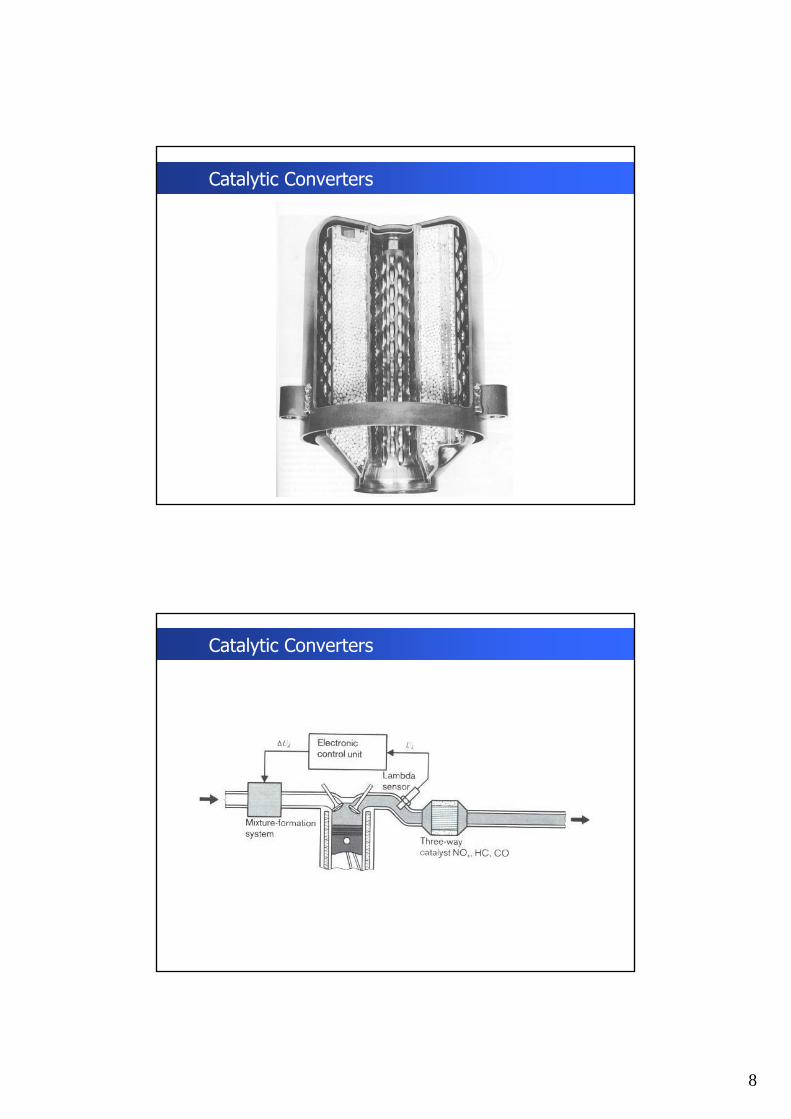
Exhaust Gas Treatment
Catalytic converters
Oxidizing catalysts for HC and CO
Reducing catalysts for NOx
Three-way catalysys for all three pollutants
Catalytic Converters
8
Catalytic Converters
Catalytic Converters
9
Catalytic Converters
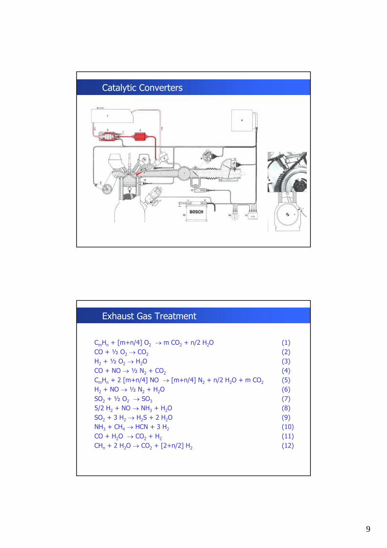
Exhaust Gas Treatment
CmHn + [m+n/4] O2 → m CO2 + n/2 H2O (1)CO + ½ O2 → CO2 (2)H2 + ½ O2 → H2O (3)CO + NO → ½ N2 + CO2 (4)CmHn + 2 [m+n/4] NO → [m+n/4] N2 + n/2 H2O + m CO2 (5)H2 + NO → ½ N2 + H2O (6)SO2 + ½ O2 → SO3 (7)5/2 H2 + NO → NH3 + H2O (8)SO2 + 3 H2 → H2S + 2 H2O (9)NH3 + CH4 → HCN + 3 H2 (10)CO + H2O → CO2 + H2 (11)CHn + 2 H2O → CO2 + [2+n/2] H2 (12)

10
Exhaust Gas Treatment
CO + ½ O2 → CO2 (2)CO + NO → ½ N2 + CO2 (4)In lean mixtures reaction (2) is dominant – O2 is present CO is reduced by oxidation and insufficient CO for the relatively slow
reaction(4).
CO + H2O → CO2 + H2 (11)CHn + 2 H2O → CO2 + [2+n/2] H2 (12)In rich mixtures reactions (11) and (12) have to be faster.
Exhaust Gas Treatment

11
Emission Regulations – Road Simulations
Emission Regulations – Exhaust Gas Emissions

12
Emission Regulations – Chasis Dynamometers
Emission Regulations – Chasis Dynamometer

13
Emission Regulations – Chasis Dynamometer
Emission Regulations – Exhaust Gas Emissions
14
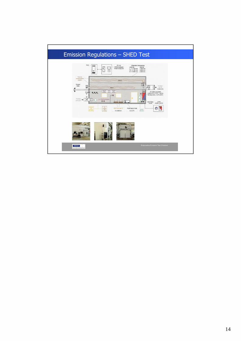
Emission Regulations – SHED Test