maintenance of india mark -ii hand pump · maintenance of india mark-i! hand pump archiv 102224 hun...
TRANSCRIPT

Do-it-yourself Maintenance of India Mark-I! Hand Pump
ARCHIV 102224
Hun F—


0
MAINTENANCE OF INDIA MARK -II HAND PUMP
Mahesh Mishra
Water from stream and open well usually carries disease,
but the tube wells are sealed to protect harmful germs. The deep
well Hand Pump is one of the safest source of clean water.
Generally it seems that in comparision to other Hand Pumps India
Mark-il Hand Pumps are used frequentely. To get fresh water
from the pump it is necessary that the hand pump should always
work properly and effectively. For good service it is also necessary
that the Hand Pump is installed properly and the maintenance
has been done periodically.
WORKING PRINCIPLE OF.INDIA MARK -II HAND PUMP AND
ThEIR PARTS:
India Mark - II Hand Pump is simply working on the principle
of reciprocating pump. Its operation can be briefed as under:
When the plunger is raised (upward stroke), the space in the
cylinder below the plunger fills with air from the suction pipe. On
the downward stroke the entrapped air is compressed between
plunger and the bottom of the cylinder. Then air lifts the plunger
valve and escape through the priming water. On the next up stroke
more air will be drawn out of the pipe and the water will rise
higher. On the next downward stroke the plunger and valve pass through the water. When the plunger reaches the bottom of the
cylinder and stops, the plunger valve closes, thus trapping the
water above the plunger. On the next up stroke

2
the plunger will lifted out from the pump.
The India Mark-Il Pump can be divided by function into three
main parts
1) The Pump stand assembly at top of the well (Pump head
assembly see fig. 1).
FIg. 1
Cover bolt washer
Chain bolt &
Connecting
Chain
Head assembly
Water tank assembly
Bolt, nut, washer & che:k nut
Piateform' Leg
Casing pipe

3
2) The Pump cylinder assembly in contact with water (cylinder
assembly See fig. 2).
Yoke body
Rubber seating
Specer
Follower
Cylinder body
Rubber Seat retainer
Check valve guide
Sealing ring
Rubber Seating
Check valve sheet
Reducer cap.
Plunger rod
Reducer cap
upper valve sheet
Sealing ring
Pump bucket
Pump bucket'
Brass

4
3) The connecting assembly which the pump stand and
cy!inder with the help of riser main pipes and connecting pump
rods.
PRECAUTION TO BE TAKEN BEFORE USING THE INDIA
MARK -II HAND PUMP:
To increase the life and for better performance of the pump,
following points should be remember before using the Hand
Pump:
i) Do not use the Hand Pump roughly.
ii) You should operate the pump handle with slow and long stroke.
iii) You should try to keep the area around the platform dry and
don't let water collect around the.platform.
iv) Make the proper arrangement for the disposal of waste water
and if it is possible then us& the waste water for nearby gardening
or by constructing soakage pit. It will avoid collection of waste
water around the Hand Pump.
Soakage pit is easy to construct and can be made with locally
available materials. It is a simple rectangular pit in which brick
ballast of different size and soil is filled up in pit and now waste
water will fall in soakage pit through open channel: Waste water
being absorbed in the soil of soakage pit. It does not allow to collect
water nearby and also helps to make space clean (See fig. 3).
(Ag. 3)

5
HAND PUMPS TROUBLE AND REMEDIES
S. Trouble Likely Cause Remedy No.
1. Pump a. It is due to no water at Development of the Handle the source and well is boring should be done works easily dry. properly. If possible but rio water then cylinder may be
delivered, lowered below water level in boring by
increasing the riser
pipe and pump rod.
OR
b. Pump has lost its Prime the pump. Priming.
OR
c. The cylinder cup Replace the cylinder
washer (leather) may cup washer by new.
be worn out.
OR
d. Pump rod joints may Check the all joints be opened. of the pump rods
and tightned it.
OR
e. Due to broken of Pump Broken pump rod
Rod. must be renewed
and this usually
means pulling the drop pipe and
cylinder out of the
bore well.

6
S. Trouble Likely cause Remedy No.
f. Hole in Suction Pipe. Renew suction pipe.
Cylinder may be
lowered below water
table in bore well.
OR
g. Leakage at base Check the cylinder
of cylinder, gasket. If require
then renew cylinder'
gasket.
OR
h. The Pump Cylinder Replace the Pump
may be cracked. cylinder by new.
OR
1. The suction pipe may Dismantle the
be plugged. suction pipe and
clear it.
2. Pump runs a. Plunger leathers badly Renew Leathers.'
but delivers warn out.
only a small
quantity of
water.
b. Refilling capacity of Make the proper
bore well is not development of the
enough. bore well.
OR
a. Valve leaking. Repair/renew valve.

7
S. Trouble Likely cause Remedy No.
3. Pump needs a. Pump has lost its Prime the pump.
too many priming.
strokes to
start
Pumping.
OR
b. The cylinder cup seals Renew the cylinder
may be worn out. cup seals.
4. Pump's a. Suction pipe plugged. Remove the pump
handle up below pump and clean out suction
springs up cylinder, pipe. If well has filled
after down with dirt upto suction
stroke. pipe, then the pipe
should be cut off.
OR
b. Suction pipe is too Replace it with larger
small. suction pipe.
OR
c. Water table is too far Place the cylinder
below from pump nearer to water.
cylinder assembly.
5. Pump is a. Pump handle or other Tighten the loose
noisy working parts of the parts.
pump are loose.
OR
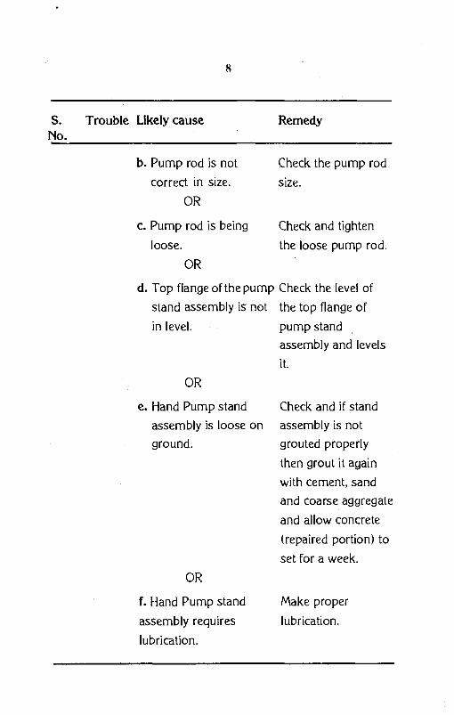
8
S. Trouble Likely cause Remedy No.
b. Pump rod is not check the pump rod
correct in size. size.
OR
c. Pump rod is being Check and tighten
loose, the loose pump rod.
OR
d. Top flange of the pump Check the level of
stand assembly is not the top flange of
in level. pump stand
assembly and levels
it.
OR
e. Hand Pump stand Check and if stand
assembly is loose on assembly is not
ground. grouted properly
then grout it again
with cement, sand
and coarse aggregate
and allow concrete
(repaired portion) to
set for a week.
OR
f. Hand Pump stand Make proper
assembly requires lubrication.
lubrication.

9
TOOLS REQUIRED FOR DISMANTELLING OF THE HAND
PUMP:
Pump dismantelling may be required for rectification of previ-
ously mentioned trouble. So for as repair and dismantelling of pump
is concerned, it is necessary that one should arrange some special
tools as detailed below:
It will help at the time of pulling and lowering
of riser pipe (see fig. 4). If self locking clamp
is not available then arrange/fabricate two
pieces of such type of clamp (see fig. 4A).
IFIg. 4A)
1. Self Locking
Clamp/Locking
Clamp
(Fig. 4)

It helps to attach the chain with handle and
will be use between chain coupler and head
assembly flange (See Fig-5).
As per requirement, pumprod can be lift
out with the help of lifting tool (see fig 6).
(Fig. 6)
10
Size as per requirement. 2. Pipe wrench,
Slide Wrench
and Spanners.
3. Tool for
holding the chain coupler
(Fig. 5)
4.Toolfor lifting/lowering
of the pump rod.
11
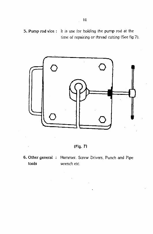
5. Pump rod vice: It is use for holding the pump rod at the
time of repairing or thread cutting (See fig 7).
(Fig. 7)
6. Other general : Hammer, Screw Drivers, Punch and Pipe
tools wrench etc.

D!SMANTEWNG OF PUMP
12
• For dismaritelling of pump for repairing, at first remove the
inspection cover from head assembly (See fig 8).
(Fig. 8)

13
• Fix the tool for holding the chain coupler inside the head
assembly. (See fig - 9)
(Fig. 9)

14
• Release the chain with handle after loosing the nut and bolt
in the upward position of the handle (see fig- 10).
(Fig. 10)

15
• Now, carefully release the handle axle by using the punch and
hammer. Again release the handle and flange bolts from head
assembly.
• Insert the pipe spanners in the both side holes of the
assembly and lift the head assembly in upward direction (see
fig-
(Fig. 11)
• Fix the pump rod vice inthe flange of water tank after lifting
of head assembly in upward direction and make assure the
holding of pump rod with the vice.
• Rotate the head after loosing the lock nut of head
assembly.Remove the chain assembly and head assembly.

16
• Remove the pump rod vice after lifting the pump rod in upward
direction with the help of lifter (pump rod clamp). Remove the
lifter after lowering of pump rod in downward direction (see
fig 12).
• Again hold the riser main pipe by self locking clamp/locking
clamp and remove the water tank after loosing of bolts of
bottom flange of water tank.
(Fig. 12)

17
• Collect the riser main pipe and pump rodat a dean place after
dismantelling. Remove the self locking damp/locking clamp
at the time of dismantelling of last riser pipe and pump rod.
• Dismantle the last riser pipe and pump rod from cylinder by
hand after pulling the last pipe connected with cylinder assembly
and to the last pump rod.
• Check the all threads of the dismantelled pump rod and riser
pipe and remove the rust & dust with help of emery paper.
If it is necessary then make the new thread on the riser
pipe/pump rod. If the pump rod has been damaged/bend, it
is advisable to replace the old (damaged) pump rod by new.
ASSEMBLY OF THE PUMP:
After repairing reassemble the pump properly - As per following
instructions:
• At first joint the plunger rod with pump rod (first pump rod)
and pump cylinder with riser pipe (first pipe) and tighten
pro perty applying the safeda on the threads. After tighten
the pump rod and riser pipe if you feel their are excess safeda
then remove it otherwise it will increase the impurities in the
tube well.
• Now lower the cylinder, first pump rod & first riser pipe in
the tube well through the pump stand assembly.
• Properly hold the riser pipe with the self locking clamp/clamp.
Again joint the first pump rod with second pump rod and first
riser pipe with second pipe and tighten it properly after applying
the safeda on threads.
• Lower the pump rod and riser pipe slowly and slowly after
loosing of locking clamp. Repeat the same process upto last
pump rod and last riser pipe.

18
• Lock the last riser pipe with locking clamp.
• Mount and tighten the water tank on the threads of last riser
pipe.
• Hold the riser pipe properly with the help of pipe wrench after
tighten a small piece of pipe in ther coupling of water tank.
Release the locking clamp from stand (after loosing the riser
pipe).
• Lower the water tank carefully in down ward direction and
fix it on the flange of pump stand.
• Release the excess piece of pipe which is fitted in the coupling
of water tank.
• Tighten the all four nut and bolts of the water tank & pump stand flange.
• Lowering the last pump rod carefully in down ward direction
after fixing of lifter on the threads of last pump rod and hold
it properly in pump rod 'vice.
• Release the lifter from pump rod after properly resting of pump
rod vice on water tank.
• Lowering the pump head through pump rod in down ward
direction up to pump rod vice and tighten the chain to pump
rod (up to three or four threads only ) at this time.
• Tighten the chain coupler by the revolving of pump rod.
• Put the chain coupler holding tool inside the pump rod.
• Allow the lowering of pump rod (after loosing of pump rod
vice) up to resting of chain coupler on chain coupler holding
tool.
• Release the pump rod vice after pulling the pump head in up
ward direction with the help of pipe spanners.

19
• Rest the properly pump head on water tank after carefully
lowering of pump head in down ward direction.
• Put the handle assembly in side the pump head.
• Insert the handle axle inside the hole with the help of punch
and hammer. Tighten the all nuts with the help of spanner.
• Connect the chain with handle and be sure that handle shall
be in upward position at the time of connection.
• Tighten the nuts of chain & handle by spanner and make the
proper lubrication on chain with grease.
• Make the handle in down ward direction and release the tool
(tool for holding the chain coulper).
• Now, be assure that all nut & bolts are tighten properly and
after assuring mount the inspection cover on head assembly
and tighten it.
Finally, start the pumping but it is advisable not to use the water at this time.
As chlorination of tube well is necessary after repairing work
therefore pour the chlorine solution into tube well. Remember
that hand pump must not be used at least for six hours after
chlorination.

IERT-CDRT-ISD-flIys -39
This work was carried out with the aid of a grant from International Development Research Centre, Ottawa, Canada.
INFORMATION SERVICE DIVISION Centre for Development of Rural Technology Institute of Engg. & Rural Technology 26, Chatham Lines, Allahabad - 211
Printed by :- Saraswati Offset Printers: 640888