maintenance of heat exchangers condenserssaharapcc.skills4success.co/spcc/tech/rtfhe/lesson...
TRANSCRIPT
Heat Exchanger Maintenance Maintenance Of Heat Exchangers & Condensers
MAINTENANCE OF HEAT
EXCHANGERS & CONDENSERS
Objectives
At the end of the lesson, the trainees will understand the maintenance of heat exchangers and condensers.
1.0 MAINTENANCE OF HEAT EXCHANGERS AND CONDENSERS 1.1 LOCATING AND STOPPING TUBE LEAKS IN LARGE HEAT
EXCHANGERS Internal leaks in surface heat exchangers are found in the tubes or where the tubes pass through the tube sheets. Checking for leaks in a large heat exchanger is done after the component has been cleaned sufficiently to permit a thorough inspection. 1.2 LOCATING HEAT EXCHANGERS AND CONDENSERS
LEAKS The two methods commonly used to locate leaks in large heat exchangers are : 1. A vacuum test and 2. A dye test 1.2.1 VACUUM TEST The vacuum test is a common check on condensers and other heat exchangers that are run under a vacuum. With the component’s water boxes open to the atmosphere, a vacuum is drawn on the shell side. In most cases, pumps are used to evacuate the air in the shell; however, if a condenser is being run at reduced load with one half open, a vacuum already exists on the steam (shell) side. To make the test, a material such as kitchen plastic wrap is placed over both tube sheets so that it covers the openings of the tubes at both ends. The tube sheets are wetted first so that the plastic wrap will cling to the surfaces. Sheets of the wrap are overlapped and pressed tightly to make sure that the sheets adhere to each other. Since the wrap covers both ends of a leaking tube, it will be drawn into the tube. A large leak might even burst the wrap into the tube opening. Soap suds and foam can also be used for this type of leak testing. Suds or light foam is brushed over the tube sheets. The worker can see where the substance is drawn into any leaking tubes, but a film remains over tubes that do not have leaks.

Heat Exchanger Maintenance Maintenance Of Heat Exchangers & Condensers
1.2.2 DYE TEST The dye test is used on condensers as well as on other types of surface heat exchangers. The shell side of the component is flooded with water that contains a fluorescent dye. Leaks in tubes or where tubes pass through the tube sheets will become evident when the area is exposed to black light from an ultraviolet lamp. The lamp is directed over the tube sheet; any dye that comes through from the shell will glow green to indicate the presence of a leak. This test is especially good for finding small leaks that cannot be detected with a vacuum test. (An extra precaution may be required when performing a dye test : because many main steam condensers are suspended below the turbine, jacks and supports must be placed under the shell before it is flooded to support and the weight of the water.)
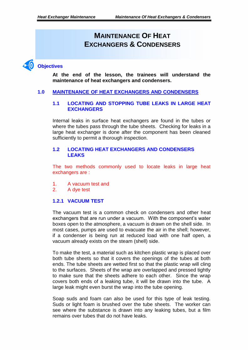
2.0 SEALING LEAKS IN CONDENSERS AND HEAT EXCHANGERS The two methods used to seal leaks in tubes and where tubes pass through tube sheets are : 1. Plugging and 2. Welding. Plugging is generally done to seal a leak within a tube; plugs are inserted into each end of the leaking tube so that there is no flow through the tube. Tubes may be welded to seal leaks between tubes and tube sheets, or tube ends may be welded over with plugs to seal a leaking tube. Plugs for leaking tubes are available in several types. The type most commonly used is the tapered plug, which is shaped like a cork or rubber stopper for a bottle or jar and is used in a similar fashion. The tapered plug is pushed firmly into the tube opening and then driven in tightly with a hammer. Tapered plugs may be made of a fibrous material that tends to swell when soaked to make an even tighter sea in the end of a tube, or they may be made of metal. Some metal plugs are threaded so that they can be screwed into the ends of leaking tubes. Like wood or sheet-metal screws, they cut their own threads in the relatively soft metal of the tube. There are also two general styles of expandable plugs. One is a rubber doughnut sandwiched between two large washers with a bolt through the middle (Fig. 4-4-1(a). When the bolt is tightened, the rubber expands to make a tight seal in the tube end. The second kind is an expandable metal plug - a tapered plug of soft metal with a hard metal pin in the center. The cross-section of this type of plug is shown in Fig. 4-1(b). When the pin is driven in with a hammer, the softer metal expands to make a tight seal.
Heat Exchanger Maintenance Maintenance Of Heat Exchangers & Condensers
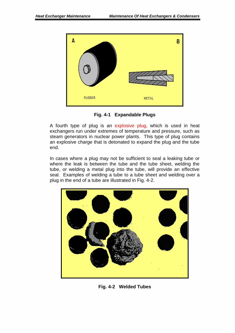
Fig. 4-1 Expandable Plugs A fourth type of plug is an explosive plug, which is used in heat exchangers run under extremes of temperature and pressure, such as steam generators in nuclear power plants. This type of plug contains an explosive charge that is detonated to expand the plug and the tube end. In cases where a plug may not be sufficient to seal a leaking tube or where the leak is between the tube and the tube sheet, welding the tube, or welding a metal plug into the tube, will provide an effective seal. Examples of welding a tube to a tube sheet and welding over a plug in the end of a tube are illustrated in Fig. 4-2.
Fig. 4-2 Welded Tubes
Heat Exchanger Maintenance Maintenance Of Heat Exchangers & Condensers
Accurate recordkeeping is essential when tubes are plugged in heat exchangers. A certain percentage of the tubes can be plugged before the efficiency of the component is significantly affected. If accurate records are kept of tube plugging, then tube replacement can be planned in advance as the maximum percentage is approached. Accurate records also allow plant personnel to check during routine maintenance and cleaning to make sure that plugs have not come out of tubes that have been plugged.
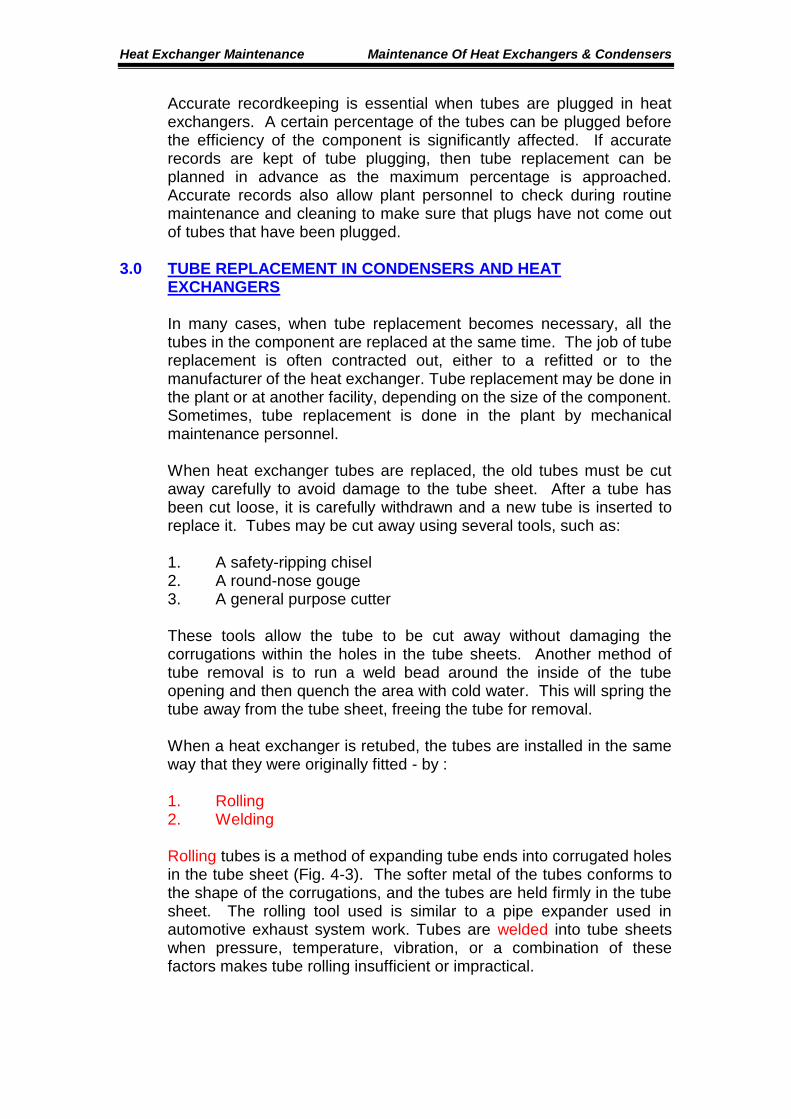
3.0 TUBE REPLACEMENT IN CONDENSERS AND HEAT EXCHANGERS In many cases, when tube replacement becomes necessary, all the tubes in the component are replaced at the same time. The job of tube replacement is often contracted out, either to a refitted or to the manufacturer of the heat exchanger. Tube replacement may be done in the plant or at another facility, depending on the size of the component. Sometimes, tube replacement is done in the plant by mechanical maintenance personnel. When heat exchanger tubes are replaced, the old tubes must be cut away carefully to avoid damage to the tube sheet. After a tube has been cut loose, it is carefully withdrawn and a new tube is inserted to replace it. Tubes may be cut away using several tools, such as: 1. A safety-ripping chisel 2. A round-nose gouge 3. A general purpose cutter These tools allow the tube to be cut away without damaging the corrugations within the holes in the tube sheets. Another method of tube removal is to run a weld bead around the inside of the tube opening and then quench the area with cold water. This will spring the tube away from the tube sheet, freeing the tube for removal. When a heat exchanger is retubed, the tubes are installed in the same way that they were originally fitted - by : 1. Rolling 2. Welding Rolling tubes is a method of expanding tube ends into corrugated holes in the tube sheet (Fig. 4-3). The softer metal of the tubes conforms to the shape of the corrugations, and the tubes are held firmly in the tube sheet. The rolling tool used is similar to a pipe expander used in automotive exhaust system work. Tubes are welded into tube sheets when pressure, temperature, vibration, or a combination of these factors makes tube rolling insufficient or impractical.
Heat Exchanger Maintenance Maintenance Of Heat Exchangers & Condensers
Fig. 4-3 Rolling Tubes
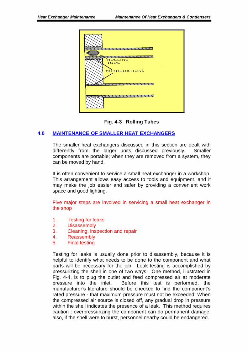
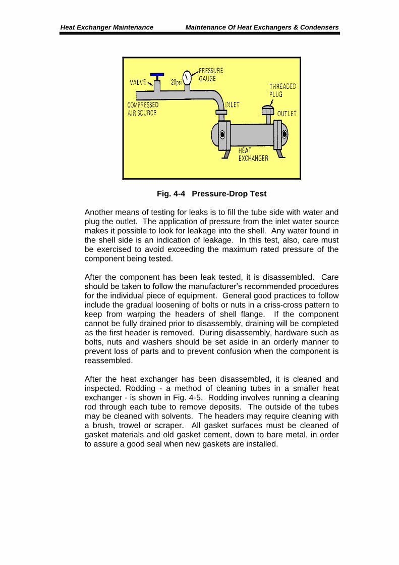
4.0 MAINTENANCE OF SMALLER HEAT EXCHANGERS The smaller heat exchangers discussed in this section are dealt with differently from the larger units discussed previously. Smaller components are portable; when they are removed from a system, they can be moved by hand. It is often convenient to service a small heat exchanger in a workshop. This arrangement allows easy access to tools and equipment, and it may make the job easier and safer by providing a convenient work space and good lighting. Five major steps are involved in servicing a small heat exchanger in the shop : 1. Testing for leaks 2. Disassembly 3. Cleaning, inspection and repair 4. Reassembly 5. Final testing Testing for leaks is usually done prior to disassembly, because it is helpful to identify what needs to be done to the component and what parts will be necessary for the job. Leak testing is accomplished by pressurizing the shell in one of two ways. One method, illustrated in Fig. 4-4, is to plug the outlet and feed compressed air at moderate pressure into the inlet. Before this test is performed, the manufacturer’s literature should be checked to find the component’s rated pressure - that maximum pressure must not be exceeded. When the compressed air source is closed off, any gradual drop in pressure within the shell indicates the presence of a leak. This method requires caution : overpressurizing the component can do permanent damage; also, if the shell were to burst, personnel nearby could be endangered.
Heat Exchanger Maintenance Maintenance Of Heat Exchangers & Condensers
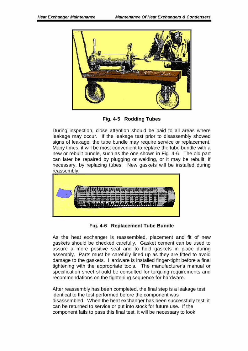
Fig. 4-4 Pressure-Drop Test Another means of testing for leaks is to fill the tube side with water and plug the outlet. The application of pressure from the inlet water source makes it possible to look for leakage into the shell. Any water found in the shell side is an indication of leakage. In this test, also, care must be exercised to avoid exceeding the maximum rated pressure of the component being tested. After the component has been leak tested, it is disassembled. Care should be taken to follow the manufacturer’s recommended procedures for the individual piece of equipment. General good practices to follow include the gradual loosening of bolts or nuts in a criss-cross pattern to keep from warping the headers of shell flange. If the component cannot be fully drained prior to disassembly, draining will be completed as the first header is removed. During disassembly, hardware such as bolts, nuts and washers should be set aside in an orderly manner to prevent loss of parts and to prevent confusion when the component is reassembled. After the heat exchanger has been disassembled, it is cleaned and inspected. Rodding - a method of cleaning tubes in a smaller heat exchanger - is shown in Fig. 4-5. Rodding involves running a cleaning rod through each tube to remove deposits. The outside of the tubes may be cleaned with solvents. The headers may require cleaning with a brush, trowel or scraper. All gasket surfaces must be cleaned of gasket materials and old gasket cement, down to bare metal, in order to assure a good seal when new gaskets are installed.
Heat Exchanger Maintenance Maintenance Of Heat Exchangers & Condensers
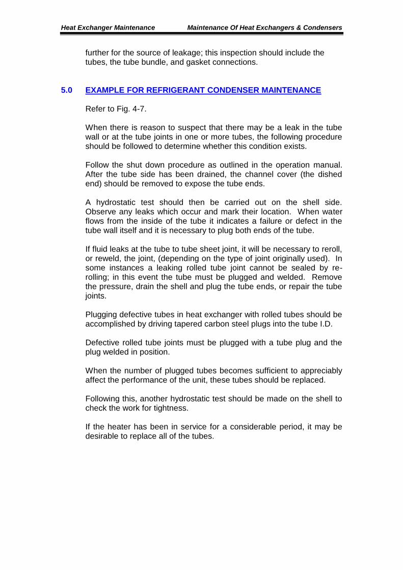
Fig. 4-5 Rodding Tubes During inspection, close attention should be paid to all areas where leakage may occur. If the leakage test prior to disassembly showed signs of leakage, the tube bundle may require service or replacement. Many times, it will be most convenient to replace the tube bundle with a new or rebuilt bundle, such as the one shown in Fig. 4-6. The old part can later be repaired by plugging or welding, or it may be rebuilt, if necessary, by replacing tubes. New gaskets will be installed during reassembly.
Fig. 4-6 Replacement Tube Bundle As the heat exchanger is reassembled, placement and fit of new gaskets should be checked carefully. Gasket cement can be used to assure a more positive seal and to hold gaskets in place during assembly. Parts must be carefully lined up as they are fitted to avoid damage to the gaskets. Hardware is installed finger-tight before a final tightening with the appropriate tools. The manufacturer’s manual or specification sheet should be consulted for torquing requirements and recommendations on the tightening sequence for hardware. After reassembly has been completed, the final step is a leakage test identical to the test performed before the component was disassembled. When the heat exchanger has been successfully test, it can be returned to service or put into stock for future use. If the component fails to pass this final test, it will be necessary to look
Heat Exchanger Maintenance Maintenance Of Heat Exchangers & Condensers
further for the source of leakage; this inspection should include the tubes, the tube bundle, and gasket connections.
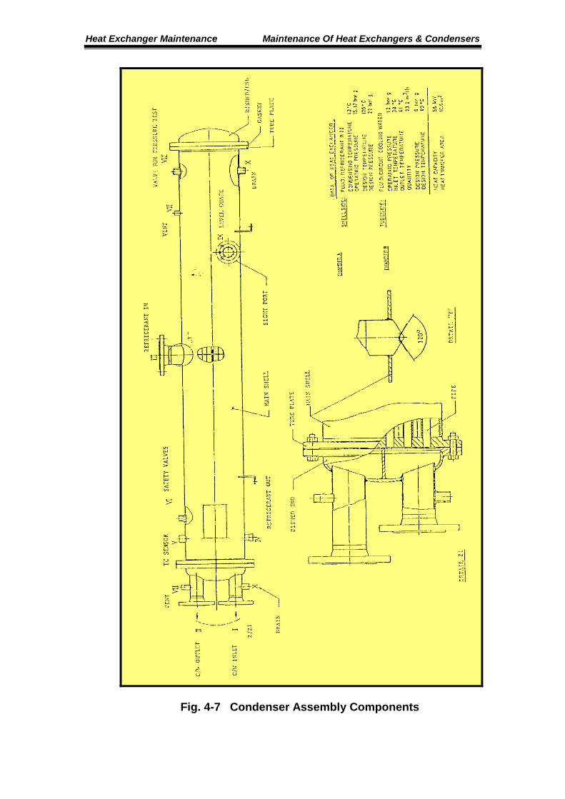
5.0 EXAMPLE FOR REFRIGERANT CONDENSER MAINTENANCE Refer to Fig. 4-7. When there is reason to suspect that there may be a leak in the tube wall or at the tube joints in one or more tubes, the following procedure should be followed to determine whether this condition exists. Follow the shut down procedure as outlined in the operation manual. After the tube side has been drained, the channel cover (the dished end) should be removed to expose the tube ends. A hydrostatic test should then be carried out on the shell side. Observe any leaks which occur and mark their location. When water flows from the inside of the tube it indicates a failure or defect in the tube wall itself and it is necessary to plug both ends of the tube. If fluid leaks at the tube to tube sheet joint, it will be necessary to reroll, or reweld, the joint, (depending on the type of joint originally used). In some instances a leaking rolled tube joint cannot be sealed by re-rolling; in this event the tube must be plugged and welded. Remove the pressure, drain the shell and plug the tube ends, or repair the tube joints. Plugging defective tubes in heat exchanger with rolled tubes should be accomplished by driving tapered carbon steel plugs into the tube I.D. Defective rolled tube joints must be plugged with a tube plug and the plug welded in position. When the number of plugged tubes becomes sufficient to appreciably affect the performance of the unit, these tubes should be replaced. Following this, another hydrostatic test should be made on the shell to check the work for tightness. If the heater has been in service for a considerable period, it may be desirable to replace all of the tubes.
Heat Exchanger Maintenance Maintenance Of Heat Exchangers & Condensers
Fig. 4-7 Condenser Assembly Components
Heat Exchanger Maintenance Maintenance Of Heat Exchangers & Condensers
5.1 TUBE PLUGGING The method of tube plugging to be used will depend on a number of factors such as tube sheet thickness, location of leak, design pressure and temperature. Plugging is used on the low pressure heat exchangers when there has been no damage to the tube hole in the tube sheet. The plug is driven into the I.D. of the tube until it is tight. The plug material should be rolled yellow brass for non-ferrous tubes and cold rolled carbon steel for steel tubes. The plug should be approximately 38 mm long and tapered with one end of the plug 0.4 to 0.5 mm larger than the measured tube I.D. and the opposite end 0.4 to 0.5 mm smaller than the measured I.D. of the tube. After the defective tube(s) have been plugged, the hydrostatic test should be carried out again to check the tightness of the plugs. If leakage persists, release pressure and again give tube a slight rolling, repeating until the joint is sealed. It is better to use several repetitions to get the joint tight then to attempt doing it all at one time and risk losing a tube. When no more leaks are evident the disched end cover is reinstalled and the tubes are then hydrostatically tested. During this test the tube sheet joint is checked and also the tubes are rechecked as the internal pressure may expand a cracked tube and show up a leak not visible under the shell test. Such a leak will be evident by a loss in test pressure over a pre-determined length of time. Water leakage through the tubes will accumulate in the bottom of the shell. 5.2 TUBE REMOVAL If preliminary checks have definitely established the presence of leaking tubes, these recommended steps should be followed : 1. Remove fluid and refrigerant from the vessel 2. Insulated heads, if used, should be removed. Remove
refrigerant lines and fluid lines (if necessary). Remove condenser heads
3. To locate individual tube leaks follow this procedure :
a. Seal fluid connections and install a fitting to permit connection to fluid side (shell) of the condenser.
Heat Exchanger Maintenance Maintenance Of Heat Exchangers & Condensers
b. Using air, nitrogen, carbon dioxide or other suitable non-
condensable for pressure, carefully bring pressure to not more than the specified test pressure (maximum allowable pressure).
c. With soap solution and brush cover the face area of both
tube sheets. Leaks will appear in the form of bubbles, or as a fine foam (with small leaks). Mark location of all leaks with chalk or crayon.
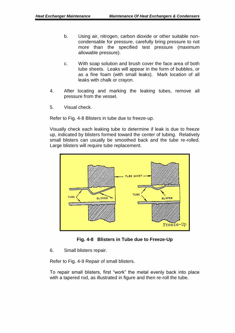
4. After locating and marking the leaking tubes, remove all
pressure from the vessel. 5. Visual check. Refer to Fig. 4-8 Blisters in tube due to freeze-up. Visually check each leaking tube to determine if leak is due to freeze up, indicated by blisters formed toward the center of tubing. Relatively small blisters can usually be smoothed back and the tube re-rolled. Large blisters will require tube replacement.
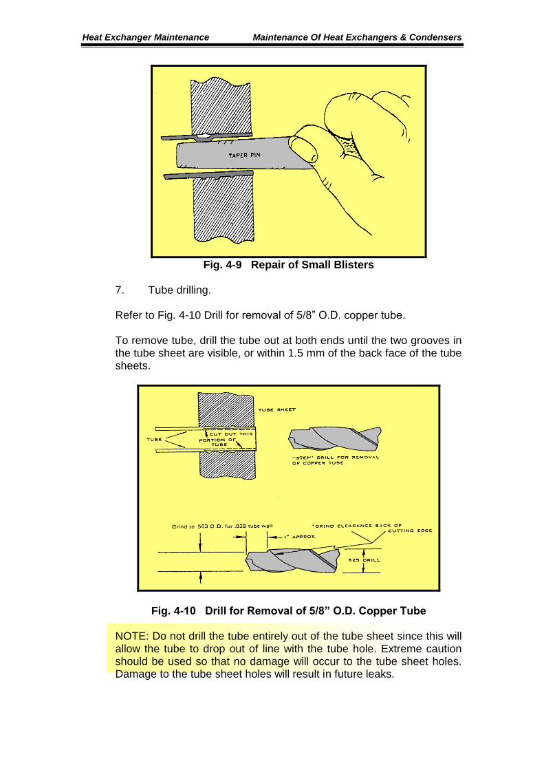
Fig. 4-8 Blisters in Tube due to Freeze-Up 6. Small blisters repair. Refer to Fig. 4-9 Repair of small blisters. To repair small blisters, first “work” the metal evenly back into place with a tapered rod, as illustrated in figure and then re-roll the tube.
Heat Exchanger Maintenance Maintenance Of Heat Exchangers & Condensers
Fig. 4-9 Repair of Small Blisters
7. Tube drilling. Refer to Fig. 4-10 Drill for removal of 5/8” O.D. copper tube. To remove tube, drill the tube out at both ends until the two grooves in the tube sheet are visible, or within 1.5 mm of the back face of the tube sheets.
Fig. 4-10 Drill for Removal of 5/8” O.D. Copper Tube NOTE: Do not drill the tube entirely out of the tube sheet since this will allow the tube to drop out of line with the tube hole. Extreme caution should be used so that no damage will occur to the tube sheet holes. Damage to the tube sheet holes will result in future leaks.
Heat Exchanger Maintenance Maintenance Of Heat Exchangers & Condensers
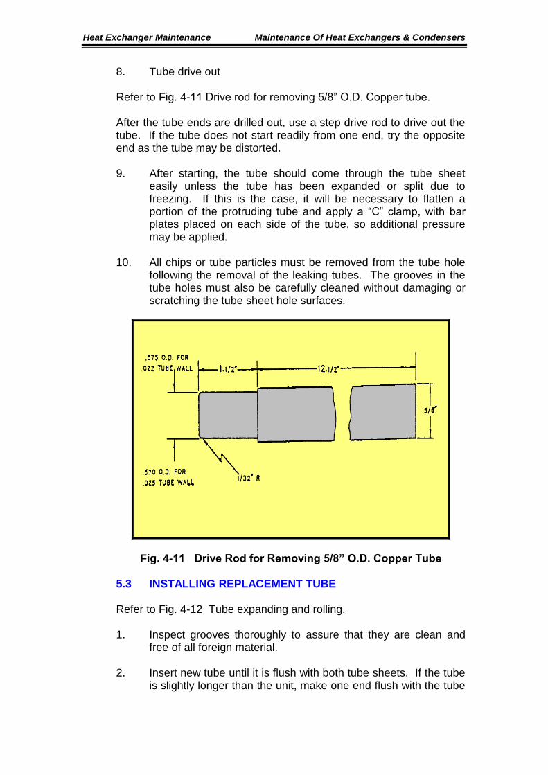
8. Tube drive out Refer to Fig. 4-11 Drive rod for removing 5/8” O.D. Copper tube. After the tube ends are drilled out, use a step drive rod to drive out the tube. If the tube does not start readily from one end, try the opposite end as the tube may be distorted. 9. After starting, the tube should come through the tube sheet
easily unless the tube has been expanded or split due to freezing. If this is the case, it will be necessary to flatten a portion of the protruding tube and apply a “C” clamp, with bar plates placed on each side of the tube, so additional pressure may be applied.
10. All chips or tube particles must be removed from the tube hole
following the removal of the leaking tubes. The grooves in the tube holes must also be carefully cleaned without damaging or scratching the tube sheet hole surfaces.
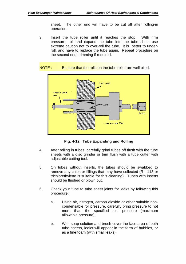
Fig. 4-11 Drive Rod for Removing 5/8” O.D. Copper Tube 5.3 INSTALLING REPLACEMENT TUBE Refer to Fig. 4-12 Tube expanding and rolling. 1. Inspect grooves thoroughly to assure that they are clean and
free of all foreign material. 2. Insert new tube until it is flush with both tube sheets. If the tube
is slightly longer than the unit, make one end flush with the tube
Heat Exchanger Maintenance Maintenance Of Heat Exchangers & Condensers
sheet. The other end will have to be cut off after rolling-in operation.
3. Insert the tube roller until it reaches the stop. With firm
pressure, roll and expand the tube into the tube sheet use extreme caution not to over-roll the tube. It is better to under-roll, and have to replace the tube again. Repeat procedure on the second end, trimming if required.
NOTE : Be sure that the rolls on the tube roller are well oiled.
Fig. 4-12 Tube Expanding and Rolling 4. After rolling in tubes, carefully grind tubes off flush with the tube
sheets with a disc grinder or trim flush with a tube cutter with adjustable cutting tool.
5. On tubes without inserts, the tubes should be swabbed to
remove any chips or fillings that may have collected (R - 113 or trichlorethylene is suitable for this cleaning). Tubes with inserts should be flushed or blown out.
6. Check your tube to tube sheet joints for leaks by following this
procedure:
a. Using air, nitrogen, carbon dioxide or other suitable non-condensable for pressure, carefully bring pressure to not more than the specified test pressure (maximum allowable pressure).
b. With soap solution and brush cover the face area of both
tube sheets, leaks will appear in the form of bubbles, or as a fine foam (with small leaks).
Heat Exchanger Maintenance Maintenance Of Heat Exchangers & Condensers
7. Re-install the condenser heads using new gaskets. 8. The entire condenser should be re-tested with the pressure (air-
freon or nitrogen-freon mixture) on the refrigerant side and checked with a halide detection device.
9. As an added check, the pressure should be left in the vessel for
a 24 hour period to assure that all leaks have been eliminated. 10. After determining that the system is free of leaks, the insulation
heads should be reinstalled, the pressure removed from the vessel, a good vacuum drawn on the refrigerant side, and the unit put back into service.