maintenance manual including repair parts and …
TRANSCRIPT

TM 11-5985-383-13&P
TECHNICAL MANUAL
OPERATOR’S, UNIT, AND DIRECT SUPPORTMAINTENANCE MANUAL INCLUDING
REPAIR PARTS AND SPECIAL TOOLS LIST
MAST, ANTENNA, 30-METERAB-1 340/G
(NSN 5985-01-249-2581) (EIC: HHB)
MSE
Distribution authorized to U.S. Government agencies and their contractors for official use or foradministrative or operational purposes only. This determination was made on 17 February 1987.Other requests for the document will be referred to Commander, U.S. Army Communications-Electronics Command and Fort Monmouth, ATTN: AMSEL-LC-LEO-P-MM-T, Fort Monmouth, NewJersey 07703-5007.DESTRUCTION NOTICE - Destroy by any method that will prevent disclosure of contents orreconstruction of the document.
HEADQUARTERS, DEPARTMENT OF THE ARMY1 MARCH 1997

TM 11-5985-383-13&P

TM 11-5985-383-13&P
WARNING
Do not erect mast within 200 feet of electrical wires. Bodily injury or death could result fromelectrical shock if any part of the mast or guy cables touches bare wires.
WARNING
During electrical storms or at any time there is a possibility of lightning strike, personnel must notattempt to erect, retract, or operate the mast and must remain outside of the guy wire pickets.Serious injury or death could result from electrical shock due to arc-over from the mast.The presence of a ground rod, while it may somewhat reduce the probability of such an arc-over,does not eliminate the hazard.
WARNING
To prevent injury to personnel, the following equipment requires two persons to lift and carry: amast section carrier, a winch bag, the accessory bag, and the equipment bag.
WARNING
Hard hats must be worn while working in mast area to prevent head injury to personnel.WARNING
Safety goggles must be worn when hammering spikes and stakes to prevent eye injury fromsparks.
WARNING
Do not erect or lower mast if wind velocity is 30 mph or greater. Mast could topple and causeserious injury or death to personnel.Operator standing on steps be aware of guide box handles. Serious injury could result if operatorslips off steps.
WARNINGWhenever handle is removed from the center spindle to adjust individual guy, ensure handle isreturned to center spindle. Failure to do so could cause personal injury.
B

TM 11-5985-383-13&P
WARNINGNever operate release lever without keeping load or tension on all three guys, by holding winchhandle (center spindle). Failure to do so could result in wrist and/or hand injury.
WARNINGTo prevent injury, an operator must keep a hand on the guy winch handle at all times to preventslipping.
Whenever handle is removed from the center spindle to adjust individual guy, ensure handle isreturned to center spindle. Failure to do so could cause personal injury.
It is important to maintain maximum tension in winch kits No. 1 and No. 3 at all times duringerection/retraction procedures. In order to achieve maximum tension, kneel with one hand on thewinch assembly, and apply maximum hand effort to winch handle in a straight pulling motion.
WARNINGAfter completing mast installation, mark all guys with streamers or approved markers inaccordance with TB 43-0129. Failure to mark guys could result in serious injury to personnel.
WARNINGDo not disassemble mast if wind velocity is 30 mph or greater. Mast could topple and causeserious injury or death to personnel.
WARNINGWhen lowering mast, ensure lifting block is ALWAYS LOCKED SECURELY within mast section.Failure to do so could result in serious injury to personnel.
C

TM 11-5985-383-13&P
WARNING
To avoid possible injury to hand or wrist when mast is retracted, never operate release lever ofwinch kits without keeping load or tension on all three guys. To do this, hold winch handle in thecenter spindle firmly - then operate lever.It is important to maintain maximum tension in winch kits No. 1 and No. 3 at all times duringerection/retraction procedures. In order to achieve maximum tension, kneel with one hand on thewinch assembly, and apply maximum hand effort to winch handle in a straight pulling motion.To avoid possible injury to hand while guiding guy cable onto winch, wear work glove.To avoid injury to personnel and damage to equipment, manually guide guy cables onto winchesto prevent uneven winding, accumulation, and/or the bunching of cables.
WARNINGBefore lowering a mast section, disengage hoist handle by striking with hand in a direction awayfrom hoist. Handle will swing freely when disengaged. Failure to do this can cause serious injuryto personnel.The release button on the hoist operates a brake mechanism that allows controlled retraction ofthe mast. Depress button gradually to maintain positive braking action. Brake is fully releasedwhen button is completely depressed. In most cases, this will be too fast for safe control of guytension and should not be attempted.
WARNING
A change in ground conditions (i.e., heavy or prolonged rain) may cause stakes to become loose.It is essential to periodically inspect stake security. Perform PMCS checks on stakes as stated inChapter 4, table 4-1. Failure to ensure stake security could cause the mast to topple, resulting inserious injury or death to personnel.
D
TM 11-5985-383-13&P
TECHNICAL MANUAL HEADQUARTERSDEPARTMENT OF THE ARMY
No. 11-5985-383-13&P Washington, DC, 1 March 1997
OPERATOR’S, UNIT, AND DIRECT SUPPORT MAINTENANCE MANUALINCLUDING
REPAIR PARTS AND SPECIAL TOOLS LIST
MAST, ANTENNA, 30 METERAB-1 340/G
(NSN 5985-01-249-2581) (EIC: HHB)
REPORTING ERRORS AND RECOMMENDING IMPROVEMENTSYou can help improve this manual. If you find any mistakes or if you know of a way to improve theprocedures, please let us know. Mail your letter, DA Form 2028 (Recommended Changes toPublications and Blank Forms), or DA Form 2028-2 located in back of this manual direct to:Commander, US Army Communications-Electronics Command and Fort Monmouth, ATTN:AMSEL-LC-LEO-P-MM-T, Fort Monmouth, New Jersey 07703-5007. The fax number is 908532-3421, DSN 992-3421. You may also e-mail your recommendations to [email protected].
A reply will be sent to you.
*This manual supersedes TM 11-5985-383-12&P, 1 September 1991.
I

TM 11-5985-383-13&P
TABLE OF CONTENTS
PageCHAPTER 1 INTRODUCTION................................................................................................................1-1Section I General Information............................................................................................................1-1
II Equipment Description and Data........................................................................................1-2CHAPTER 2 SERVICE UPON RECEIPT AND INSTALLATION ............................................................2-1Section I Site Requirements ..............................................................................................................2-1
II Service Upon Receipt of Materiel .......................................................................................2-1III Installation Instructions .......................................................................................................2-9IV Preparation for Movement ..................................................................................................2-40V Antenna Adapter Kit............................................................................................................2-46
CHAPTER 3 OPERATING INSTRUCTIONS ..........................................................................................3-1Section I Controls and Indicators.......................................................................................................3-1
II Operation Under Usual Conditions.....................................................................................3-1III Operation Under Unusual Conditions.................................................................................3-3
CHAPTER 4 OPERATOR MAINTENANCE INSTRUCTIONS ................................................................4-1Section I Tools and Equipment..........................................................................................................4-1
II Preventive Maintenance Checks and Services (PMCS) ....................................................4-1CHAPTER 5 UNIT MAINTENANCE INSTRUCTIONS............................................................................5-1
Section I Repair Parts, Special Tools, and Support Equipment ........................................................5-1II Repainting and Refinishing Instructions .............................................................................5-1III Preventive Maintenance Checks and Services (PMCS) ....................................................5-2IV Troubleshooting Procedures ..............................................................................................5-4V Unit Maintenance for 30-Meter Mast ..................................................................................5-4VI Unit Maintenance for 30-Meter Mast Antenna Adapter Kit.................................................5-11
CHAPTER 6 DIRECT SUPPORT MAINTENANCE INSTRUCTIONS ....................................................6-1Section I General Information............................................................................................................6-1
II Tools and Equipment..........................................................................................................6-1III Removal and Replacement Procedures.............................................................................6-1
APPENDIX A REFERENCES ...................................................................................................................A-1B MAINTENANCE ALLOCATION..........................................................................................B-1C COMPONENTS OF END ITEM LIST.................................................................................C-1D NOT APPLICABLEE EXPENDABLE SUPPLIES AND MATERIAL LIST.............................................................E-1
ii

TM 11-5985-383-13&P
TABLE OF CONTENTS - Continued
IllusPage Figure
APPENDIX F OPERATOR’S, UNIT, AND DIRECT SUPPORT MAINTENANCE REPAIRPARTS AND SPECIAL TOOLS LIST
Section I Introduction ......................................................................................................F-1II Repair Parts List...............................................................................................F-1
Group 00 Mast, Antenna 30 Meter AB-1340/G . ..............................................................F-1-1 F-101 Guy Winch Kit . ................................................................................................F-2-1 F-202 Hoist (No parts authorized)03 Leg Assembly...................................................................................................F-3-1 F-304 Mast Guide Box................................................................................................F-4-1 F-405 Lifting Block......................................................................................................F-5-1 F-506 Cable Assembly RF . .......................................................................................F-6-1 F-607 Antenna Side Mount Adapter ...........................................................................F-7-1 F-708 Antenna Adapter Assembly..............................................................................F-8-1 F-8
0801 Antenna Adapter ..............................................................................................F-9-1 F-9080101 Knob Assembly ................................................................................................F-10-1 F-10
0802 Cable Assembly, W5........................................................................................F-11-1 F-1109 Guy Collar ........................................................................................................F-12-1 F-1210 Picket Location Line .........................................................................................F-13-1 F-1311 Bubble Level ....................................................................................................F-14-1 F-1412 Rotator Extension.............................................................................................F-15-1 F-1513 Mast Section Carrier . ......................................................................................F-16-1 F-1614 Hoist Support Bar.............................................................................................F-17-1 F-1715 Step Assembly . ...............................................................................................F-18-1 F-1816 Mast Section ....................................................................................................F-19-1 F-1917 Antenna Rotator (No parts authorized)
Section III Special Tools List (Not applicable)IV CROSS-REFERENCE INDEXES ....................................................................F-I-1
National stock number index....................................................................F-I-1Part number index....................................................................................F-I-2Figure and item number index .................................................................F-I-3
INDEX.....................................................................................................................................................................Index-1
iii

TM 11-5985-383-13&P
LIST OF ILLUSTRATIONS
Number Title Page
1-1 30-Meter Mast ..............................................................................................................................1-32-1 30-Meter Mast Components and Accessories (4 Sheets)............................................................2-52-2 Mast Installation Team .................................................................................................................2-102-3 Adjustable Foot Installation ..........................................................................................................2-122-4 Leg Installation .............................................................................................................................2-132-5 Leg Adjustment ............................................................................................................................2-142-6 Leveling Tripod.............................................................................................................................2-152-7 Setting Azimuth ............................................................................................................................2-162-8 Installing Detachable Steps..........................................................................................................2-182-9 Mounting Hoist .............................................................................................................................2-192-10 Installing Lifting Block...................................................................................................................2-202-11 Installing Spikes and Stakes ........................................................................................................2-212-12 Installing Guy Winch Kits..............................................................................................................2-232-13 Pulley Block and Cable Clamp Installation...................................................................................2-242-14 Preparing Guy Collars for Installation...........................................................................................2-262-15 Installing First Mast Section .........................................................................................................2-272-16 Antenna Rotator Installation .........................................................................................................2-282-17 Installing First Guy Collar and Second Mast Section ...................................................................2-302-18 Guy Installation.............................................................................................................................2-322-19 Operating Guy Winches ...............................................................................................................2-332-20 Side Mounting Adapter.................................................................................................................2-342-21 Tightening Cable Clamp...............................................................................................................2-382-22 Mast Alinement.............................................................................................................................2-412-23 Lifting Block Positioning ...............................................................................................................2-432-24 Guy Wire Stake Locations............................................................................................................2-472-25 Omni Antenna and Adapter Assembly Installation.......................................................................2-492-26 Guy Assembly Installation ............................................................................................................2-513-1 Antenna Operating Controls.........................................................................................................3-24-1 Mast Guide Box Lubrication .........................................................................................................4-54-2 Hoist Lubrication...........................................................................................................................4-64-3 Lifting Block Lubrication ...............................................................................................................4-74-4 Guy Winch Kit Lubrication ............................................................................................................4-84-5 Pulley Block Lubrication ...............................................................................................................4-94-6 Leg Assembly Lubrication ............................................................................................................4-94-7 Antenna Side Mounting Adapter Lubrication................................................................................4-105-1 Pulley Block Snap Hook Replacement.........................................................................................5-105-2 Cable Clamp Replacement ..........................................................................................................5-125-3 Antenna Adapter Maintenance.....................................................................................................5-136-1 Leg Assembly Removal and Replacement ..................................................................................6-36-2 Mast Guide Box Removal and Replacement (4 Sheets)..............................................................6-86-3 Lifting Block Removal and Replacement .....................................................................................6-126-4 Antenna Side Mounting Adapter Removal and Replacement......................................................6-146-5 Guy Collar Removal and Replacement ........................................................................................6-166-6 Picket Location Line Removal and Replacement.........................................................................6-176-7 Bubble Level Removal and Replacement ....................................................................................6-196-8 Rotator Extension Adapter Removal and Replacement...............................................................6-216-9 Mast Section Carrier Removal and Replacement ........................................................................6-226-10 Hoist Support Bar Removal and Replacement ............................................................................6-236-11 Step Assembly Removal and Replacement.................................................................................6-256-12 Mast Section Removal and Replacement ....................................................................................6-26
iv

TM 11-5985-383-13&P
LIST OF TABLES
Number Title Page
1-1 Nomenclature Cross-Reference List ............................................................................................1-21-2 Tabulated Data.............................................................................................................................1-42-1 30-Meter Mast Components and Usage ......................................................................................2-22-2 Guy Cable Release ......................................................................................................................2-362-3 Omni Antenna Adapter Kit Parts List............................................................................................2-463-1 Antenna Operating Controls.........................................................................................................3-14-1 Operator Preventive Maintenance Checks and Services.............................................................4-25-1 Unit Preventive Maintenance Checks and Services.....................................................................5-35-2 Troubleshooting............................................................................................................................5-4
v/(vi blank)

TM 11-5985-383-13&PCHAPTER 1
INTRODUCTION
Section I. GENERAL INFORMATION
1-1 SCOPE.This manual describes the Mast, Antenna, 30-Meter AB-1340/G, hereafter referred to as the 30-meter mast, and containsinstructions for the installation, operation, unit, and direct support maintenance of the equipment. It also contains TheRepair Parts and Special Tools List (RPSTL), Appendix F.
1-2 CONSOLIDATED INDEX OF ARMY PUBLICATIONS AND BLANK FORMS.Refer to the latest issue of DA Pam 25-30 to determine whether there are new editions, changes, or additional publicationspertaining to the equipment.
1-3 MAINTENANCE FORMS, RECORDS, AND REPORTS.1-3.1 Reports of Maintenance and Unsatisfactory Equipment. Department of the Army forms and procedures used forequipment maintenance will be those prescribed by DA Pam 738-750, as contained in Maintenance Management Update.
1-3.2 Reporting of Item and Packaging Discrepancies. Fill out and forward SF 364 (Report of Discrepancy (ROD)) asprescribed in AR 735-11-2/DLAR 4140.55/SECNAVINST 4355.18/AFR 400-54/MCO 4430.3J.
1-3.3 Transportation Discrepancy Report (TDR) (SF 361). Fill out and forward Transportation Discrepancy Report (TDR)(SF 361) as prescribed in AR 55-38/NAVSUPINST 4610.33C/AFR 75-18/MCO P4610.19D/DLAR 4500.15.
1-4 REPORTING EQUIPMENT IMPROVEMENT RECOMMENDATIONS (EIR).If your 30-Meter Antenna Mast AB-1340/G needs improvement, let us know. Send us an EIR. You, the user, are the onlyone who can tell us what you don’t like about your equipment. Let us know why you don’t like the design or performance;put it on an SF 368 (Product Quality Deficiency Report). Mail it to: Commander, U.S. Army Communications-ElectronicsCommand and Fort Monmouth, ATTN: AMSEL-LC-LEO-D-CS-CFO, Fort Monmouth, New Jersey 07703-5023. We’ll sendyou a reply.
1-5 ADMINISTRATIVE STORAGE.Equipment issued to and used by Army activities will have preventive maintenance performed in accordance with thePreventive Maintenance Checks and Services (PMCS) charts before being placed in administrative storage.When removing the equipment from administrative storage, the PMCS shall be performed to assure operational readiness.
1-6 DESTRUCTION OF ARMY ELECTRONICS MATERIEL.Destruction of Army electronics materiel to prevent enemy use shall be in accordance with TM 750-244-2.
1-7 WARRANTY INFORMATION.Refer to TB 11-5800-216-15 for information concerning equipment warranties.
1-1

TM 11-5985-383-13&P
1-8 NOMENCLATURE CROSS-REFERENCE LIST.Table 1-1 is a cross-reference list of common names and official nomenclature for equipment described in this manual.Official nomenclature must be used when completing report forms.
Table 1-1. Nomenclature Cross-Reference List
COMMON NAME OFFICIAL NOMENCLATURE
30-meter mast Mast, Antenna, 30-Meter, AB-1340/G
Section II. EQUIPMENT DESCRIPTION AND DATA1-9 PURPOSE AND USE.
The purpose of the 30-meter mast is to support a maximum of two antennas, either a VHF and a UHF, or two UHFantennas. This mast is used in areas where its height is required to place antenna(s) above trees or other obstacles.
1-10 EQUIPMENT CHARACTERISTICS, CAPABILITIES, AND FEATURES.
Figure 1-1 shows the 30-meter mast when fully erected without antenna(s). The mast is made up of the followingcomponents when fully erected: 24 mast sections, an antenna rotator, a rotator extension adapter, a ballrope, an antennaside mounting adapter, 3 leg assemblies with adjustable feet, a mast guide box with ground stud, a lifting block, a hoist, 4guy winch kits, 4 guy collars, 9 stakes, 15 spikes, 12 guy cables, 3 cable clamps, and 6 guy extensions. The mast alsocomes with an adapter kit. When an omni antenna is installed, the adapter kit is to be used.
NOTE
The only sure personnel protection is to adhere absolutely to the requirement that the mast not beoperated while electrical storm activity is present and that all personnel stay away from all mastparts including guys and pickets during such conditions.
1-2

TM 11-5985-383-13&P
Figure 1-1. 30-Meter Mast
1-3
TM 11-5985-383-13&P
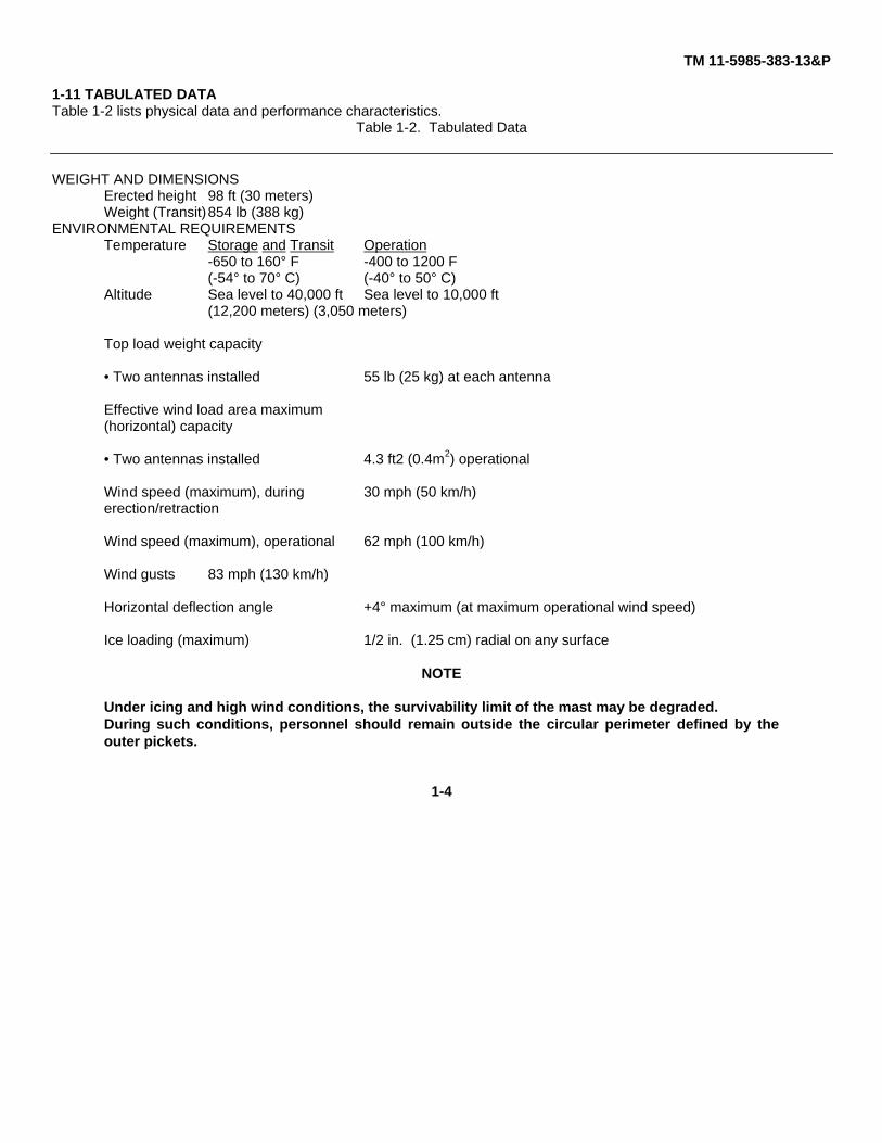
1-11 TABULATED DATATable 1-2 lists physical data and performance characteristics.
Table 1-2. Tabulated Data
WEIGHT AND DIMENSIONSErected height 98 ft (30 meters)Weight (Transit)854 lb (388 kg)
ENVIRONMENTAL REQUIREMENTSTemperature Storage and Transit Operation
-650 to 160° F -400 to 1200 F(-54° to 70° C) (-40° to 50° C)
Altitude Sea level to 40,000 ft Sea level to 10,000 ft(12,200 meters) (3,050 meters)
Top load weight capacity
• Two antennas installed 55 lb (25 kg) at each antenna
Effective wind load area maximum(horizontal) capacity
• Two antennas installed 4.3 ft2 (0.4m2) operational
Wind speed (maximum), during 30 mph (50 km/h)erection/retraction
Wind speed (maximum), operational 62 mph (100 km/h)
Wind gusts 83 mph (130 km/h)
Horizontal deflection angle +4° maximum (at maximum operational wind speed)
Ice loading (maximum) 1/2 in. (1.25 cm) radial on any surface
NOTE
Under icing and high wind conditions, the survivability limit of the mast may be degraded.During such conditions, personnel should remain outside the circular perimeter defined by theouter pickets.
1-4

TM 11-5985-383-13&P
CHAPTER 2SERVICE UPON RECEIPT AND INSTALLATION
Section I. SITE REQUIREMENTS2-1 TERRAIN CONSIDERATIONS.
WARNINGDo not erect mast within 200 feet of electrical wires. Bodily injury or death could result fromelectrical shock if any part of the mast or guy cables touches bare wires.
The best terrain for erecting the 30-meter mast is level ground, or ground that does not slope more than 3 percent. Theterrain should also have enough room to lay out guy stakes, which require 59 feet in line with the closest tripod leg. If anobstacle (rocks, trees, etc.) is in the way of a stake location, that stake can be relocated up to 3 feet inward towards tripodand 1-1/2 feet to either side of the original stake location. Properly positioned stakes are the main factor in supporting themast. The terrain texture determines the ability of a stake to support its portion of the mast.
If 12 or more blows with the hammer are required to drive in a stake, the ground is considered firm. If less than 12 blowsare required to drive in a stake, the ground is too soft, and another site should be found. If another site is not practical,anchor guy cables to stationary objects, if possible.
2-2 TRANSMISSION PATHS.
The selection of a site must also consider transmission paths for one or two antennas that will be mounted on the mast. Iftwo antennas are used, the top antenna will be approximately 98.4 feet above ground and the lower antennaapproximately 8 feet below top guy collar. These antennas shall be above terrain obstacles such as trees and buildings inthe transmit/receive paths.
Section II. SERVICE UPON RECEIPT OF MATERIEL
2-3 UNPACK EQUIPMENT.
CAUTIONDo not put weight on the packing cases. Do not turn the packing cases over or rest them inpositions other than those indicated on the outside or damage to equipment could result.
NOTE
Do not destroy packing materials. They can be reused to pack equipment for further shipment.
The 30-meter mast is transported to the site by the node support vehicle containing a full kit of mast equipment withaccessories. The equipment is carefully packed in carrying bags and mast section carriers. The following hand tools arenot included in the kit but should be on hand at the site: sledge hammer, hammer (hand claw), oil can filled with lubricatingoil (see Appendix E), pair of hand pliers (standard size), file (small with fine ridges), and a magnetic compass.
2-1

TM 11-5985-383-13&P
Table 2-1 lists kit components, accessories, and a description of usage. The equipment is listed with a reference to figure2-1, which illustrates components and accessories.
Table 2-1. 30-Meter Mast Components and Usage
REFERENCE (fig. 2-1) COMPONENT/ACCESSORY USAGE(QUANTITY)
A Mast tripod adjustable foot (3) Supports mast leg assembly(part of leg assembly)
B Leg assembly (3) Attaches to mast guide box formast support
C Step assembly (4) Mounted on a leg assembly. Enablespersonnel to climb to mast base
B, D Mast guide box a. Provides junction for legassemblies to support mast
b. Guides sections of mast forassembly and disassembly
c. Provides a ground stud forgrounding
D Hoist For raising and lowering mastD Hoist support bar Provides support for hoistE Lifting block Supports mast sections during erection
or retractionF Bubble level Indicates when mast base is level
G Foot adjustment brace Tool for adjusting feet on leg assembliesH Mast section (24) Make up erected mastI Guy collar (4) Used for connecting guy cables and
extensions to mastJ Guy winch kit (4) Holds guy cables used for supporting
mastK 15-meter guy extension cables (6) Used for support of upper part of mastL Spike (15) Secures tripod feet and winch kits
to groundM Stake (9) Secure ends of a guy cable to groundN Stake location line Used for positioning stakes in ground
at proper locationsO Feeder cable strap (6) Secures feeder cable routing along mast
2-2

TM 11-5985-383-13&P
Table 2-1. 30-Meter Mast Components and Usage - Continued
REFERENCE (fig. 2-1) COMPONENT/ACCESSORY USAGE(QUANTITY)
P Winch handle Used for winding/unwinding guy winchassembly kit drums
Q Mast section carrier (3) For moving eight mast sectionsR Antenna rotator Rotates extension adapter on top of
mastS Rotator extension adapter Holds top antenna on antenna rotatorT Antenna side mounting adapter For mounting a second or lower antennaU Cable clamp (3) Secures cable to stake footingV Antenna cable extensions Used with antenna cable to extend its
length to 200 feetW Antenna adapter assembly Used to attach antenna to mastX Guy cord stake Secure ends of guy cord to groundY Guy assembly Used to extend ground radial arms of
omni antennaZ Locating line Used for positioning stakes in ground at
proper locationsAA Tripod stake Used with locating line to properly
position guy cord stakesBB Storage bag Carry bag for guy cord stakes and
connector adapterCC Connector adapter Used to connect two antenna cables
togetherDD Winch assembly bag (4) Carrying bag for winch, winch handle,
and 12 spikes (three spikes in each bag)EE Hoist assembly bag Carrying bag for the hoist and hoist
handleFF Equipment bag Carrying bag for the following:
Mast guide boxLifting blockBubble levelGuy CollarFeeder cable straps
2-3
TM 11-5985-383-13&P
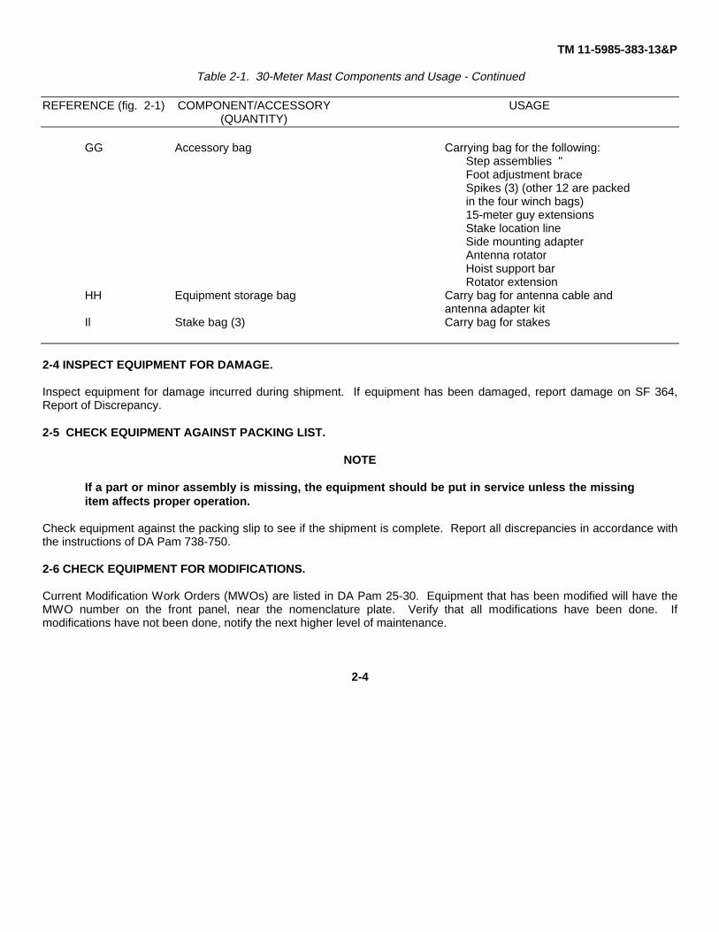
Table 2-1. 30-Meter Mast Components and Usage - Continued
REFERENCE (fig. 2-1) COMPONENT/ACCESSORY USAGE(QUANTITY)
GG Accessory bag Carrying bag for the following:Step assemblies "Foot adjustment braceSpikes (3) (other 12 are packedin the four winch bags)15-meter guy extensionsStake location lineSide mounting adapterAntenna rotatorHoist support barRotator extension
HH Equipment storage bag Carry bag for antenna cable andantenna adapter kit
Il Stake bag (3) Carry bag for stakes
2-4 INSPECT EQUIPMENT FOR DAMAGE.
Inspect equipment for damage incurred during shipment. If equipment has been damaged, report damage on SF 364,Report of Discrepancy.
2-5 CHECK EQUIPMENT AGAINST PACKING LIST.
NOTE
If a part or minor assembly is missing, the equipment should be put in service unless the missingitem affects proper operation.
Check equipment against the packing slip to see if the shipment is complete. Report all discrepancies in accordance withthe instructions of DA Pam 738-750.
2-6 CHECK EQUIPMENT FOR MODIFICATIONS.
Current Modification Work Orders (MWOs) are listed in DA Pam 25-30. Equipment that has been modified will have theMWO number on the front panel, near the nomenclature plate. Verify that all modifications have been done. Ifmodifications have not been done, notify the next higher level of maintenance.
2-4

TM 11-5985-383-13&P
Figure 2-1. 30-Meter Mast Components and Accessories (Sheet 1 of 4)
2-5

TM 11-5985-383-13&P
Figure 2-1. 30-Meter Mast Components and Accessories (Sheet 2 of 4)
2-6

TM 11-5985-383-13&P
Figure 2-1. 30-Meter Mast Components and Accessories (Sheet 3 of 4)
2-7

TM 11-5985-383-13&P
Figure 2-1. 30-Meter Mast Components and Accessories (Sheet 4 of 4)
2-8

TM 11-5985-383-13&P
Section III. INSTALLATION INSTRUCTIONS
2-7 TOOLS AND MATERIALS REQUIRED.
Tools and materials required to install the 30-meter mast are included with the mast and accessories. They consist of abubble level tube, foot adjustment brace, stake location line, and guy winch handle.
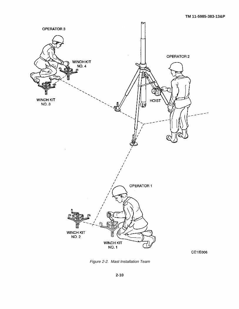
2-8 MAST INSTALLATION TEAM.
NOTEA team of three qualified personnel are required to erect the 30-meter mast.
The team, consisting of operators 1, 2, and 3, perform the following tasks (fig. 2-2):
Operator 1 attends winch kits No. 1 and No. 2.
Operator 2 is the team leader and stands by the hoist at the base of the mast, inserts mast sections into the mast guidebox, uses the lifting block, and operates hoist. Operator 2 gives directions to operators 1 and 3 that must be followedexplicitly to facilitate mast erection.
Operator 3 attends winch kits No. 3 and No. 4 (unless helping operator 2 at base of mast). Operator 3 works withoperator 1 in controlling the guy cables as mast is being erected and retracted.
2-9 INSTALLATION OF THE 30-METER MAST.
2-9.1 General. Installation of the 30-meter mast begins with the assembly of the tripod consisting of three adjustable legsand mast guide box. The tripod supports the weight of the mast; the azimuth ring on the mast guide box is used to set thecompass heading for grid north or magnetic north. Proper azimuth setting is necessary for aiming the mounted antenna tobest receive and transmit radio signals. Stakes, winch kits, and guy cables are installed to stabilize and maintain maststraightness. The mast is erected by adding one section at a time, which allows the installation team to raise the antennato any desired height up to 30 meters. During and after erection, tension on the guy cables is adjusted by operating thefour winch kits as required. The following subparagraphs describe the detailed installation procedures.
WARNINGDuring electrical storms or at any time there is a possibility of lightning strike, personnel must notattempt to erect, retract, or operate the mast and must remain outside of the guy wire pickets.Serious injury or death could result from electrical shock due to arc-over from the mast. Thepresence of a ground rod, while it may somewhat reduce the probability of such an arc-over, doesnot eliminate the hazard.
NOTE
When an operator(s) performs a step in these procedures, the operator(s) is mentioned in thatstep. This continues to the following steps until another operator(s) is mentioned.
2-9
TM 11-5985-383-13&P
Figure 2-2. Mast Installation Team
2-10

TM 11-5985-383-13&P
2-9.2 Tripod Assembly.
WARNINGTo prevent injury to personnel, the following equipment requires two persons to lift and carry: amast section carrier, a winch bag, the accessory bag, and the equipment bag.
NOTEOperators 2 and 3 perform steps a. through f.
a. Attach adjustable foot to inner leg of each leg assembly (fig. 2-3) as follows:(1) Push foot firmly into position so flat side of foot nut matches flat side of leg assembly.(2) Secure adjustable foot and leg assembly with clip.(3) Unscrew foot nut until approximately 2 inches of thread is exposed.
b. Lay mast guide box on ground (fig. 2-4). Attach one leg by lining up holes in top bracket of leg withholes in lug on side of mast guide box. Insert two drop-head pins fully and secure drop-head pinlatches.
c. Remove both pins from lower part of leg assembly and pull out inner leg until three holes areshowing. Reinsert pins through outer and inner legs to secure both parts (fig. 2-5).
d. Roll mast guide box and add second leg in similar manner.e. Turn mast guide box over completely and add third leg, following steps b. and c.f. Lift mast guide box onto legs in vertical position.
NOTE
Observe terrain in line with each leg assembly for obstruction that would prevent a stake frombeing driven into the ground. If an obstruction exists, rotate or move tripod to a better position.
g. Operator 1: Push bubble level tube into guide holes on mast guide box (fig. 2-6). Secure bubble level tube tomast guide box with locating pin. Slide protective cover to expose bubble level.
h. Set azimuth on mast guide box using the following procedure:
(1) Turn thumbscrews on azimuth ring assembly counterclockwise to loosen azimuth ring (fig. 2-7).(2) While observing compass, rotate azimuth ring so that it indicates 0 when alined with compass north.
Tighten thumbscrews.i. Operator 2: Adjust foot on each leg using adjustment brace until bubble is centered. Slide protective cover back
over bubble level. Remove bubble level tube and place inside pocket of equipment bag.
2-11

TM 11-5985-383-13&P
Figure 2-3. Adjustable Foot Installation
2-12

TM 11-5985-383-13&P
Figure 2-4. Leg Installation
2-13

TM 11-5985-383-13&P
Figure 2-5. Leg Adjustment
2-14

TM 11-5985-383-13&P
Figure 2-6. Leveling Tripod
2-15

TM 11-5985-383-13&P
Figure 2-7. Setting Azimuth
2-16
TM 11-5985-383-13&P
NOTE
Operator 3 performs steps j. and I.
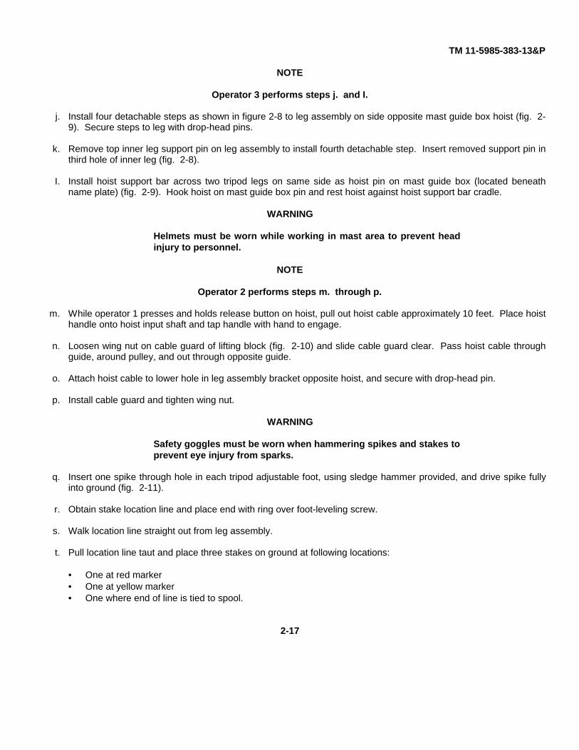
j. Install four detachable steps as shown in figure 2-8 to leg assembly on side opposite mast guide box hoist (fig. 2-9). Secure steps to leg with drop-head pins.
k. Remove top inner leg support pin on leg assembly to install fourth detachable step. Insert removed support pin inthird hole of inner leg (fig. 2-8).
I. Install hoist support bar across two tripod legs on same side as hoist pin on mast guide box (located beneathname plate) (fig. 2-9). Hook hoist on mast guide box pin and rest hoist against hoist support bar cradle.
WARNING
Helmets must be worn while working in mast area to prevent headinjury to personnel.
NOTE
Operator 2 performs steps m. through p.
m. While operator 1 presses and holds release button on hoist, pull out hoist cable approximately 10 feet. Place hoisthandle onto hoist input shaft and tap handle with hand to engage.
n. Loosen wing nut on cable guard of lifting block (fig. 2-10) and slide cable guard clear. Pass hoist cable throughguide, around pulley, and out through opposite guide.
o. Attach hoist cable to lower hole in leg assembly bracket opposite hoist, and secure with drop-head pin.
p. Install cable guard and tighten wing nut.
WARNING
Safety goggles must be worn when hammering spikes and stakes toprevent eye injury from sparks.
q. Insert one spike through hole in each tripod adjustable foot, using sledge hammer provided, and drive spike fullyinto ground (fig. 2-11).
r. Obtain stake location line and place end with ring over foot-leveling screw.
s. Walk location line straight out from leg assembly.
t. Pull location line taut and place three stakes on ground at following locations:
• One at red marker• One at yellow marker• One where end of line is tied to spool.
2-17

TM 11-5985-383-13&P
Figure 2-8. Installing Detachable Steps
2-18

TM 11-5985-383-13&P
Figure 2-9. Mounting Hoist
2-19

TM 11-5985-383-13&P
Figure 2-10. Installing Lifting Block
2-20

TM 11-5985-383-13&P
Figure 2-11. Installing Spikes and Stakes
2-21

TM 11-5985-383-13&P
NOTE
In following step, stakes should lean away from tripod leg (shacklebracket facing leg) so that edge of shackle bracket is perpendicular(visual sight) to ground. Back of stake is approximately 750 withground. Refer to figure 2-11.
u. Using sledge hammer provided, install each of the three stakes into ground to beginning of shackle bracket atmarkers.
v. Repeat steps r. through t. above for remaining six stakes along other two leg assemblies. When complete, windstake location line onto spool and store in accessory bag.
NOTE
On the mast guide box there is a ground stud available forgrounding mast.
w. If grounding equipment is available, locate ground stud on mast guide box (fig. 2-14) and ground mast accordingto FM 11-487-4.
2-9.3 Guy Winch Kit Installation. Perform the following procedure to install guy winch kits and cable clamps.
NOTE
All guy winch kits are identical. After guy winch kits are in position,install cable clamp on the kit designated number one.
a. Operators 1 and 3: Position guy winch kits as shown in figure 2-12. Open spreaders and insert pin in eachspreader to keep from closing. Drive spikes (three for each winch kit) through spreader holes fully into ground.Release three drums by turning release knobs clockwise.
b. At the guy winch kit designated number one (fig. 2-12), pull pulley block to the stake furthest out from tripod andclip to stake hole closest to the ground (fig. 2-18). Ensure there is enough slack in guy cable from the guy winchkit.
c. At pulley block (fig. 2-13), remove retainer clip from block.
d. Install cable clamp, insert pulley pin, and insert retainer clip.
e. Ensure guy cable is in the correct position to pulley block. Repeat steps c. and d. to install other cable clamps.
2-9.4 Mast Erection. While operator 2 inserts mast sections into mast guide box to erect mast, operator 3, when notattending guy winch kits No. 3 and No. 4, can assist operator 2.
WARNING
Do not erect mast if wind velocity is 30 mph or greater. Mast couldtopple and cause serious injury or death to personnel.
Operator standing on steps be aware of guide box handles. Seriousinjury could result if operator slips off steps.
2-22

TM 11-5985-383-13&P
Figure 2-12. Installing Guy Winch Kits
2-23

TM 11-5985-383-13&P
Figure 2-13. Pulley Block and Cable Clamp Installation
2-24
TM 11-5985-383-13&P
a. Operator 2: Press and hold release button on hoist. Turn handle counterclockwise to lower lifting block until it isapproximately 12 inches off ground (fig. 2-14).
b. Operator 3: Climb detachable steps on leg assembly and be ready to receive guy collars from operator 1.Operator 1: Hand operator 3 four guy collars.
c. Operator 3: Place four guy collars, with comers facing down, over top of mast guide box. Move hanging guy collarretaining halves out of the way by hanging them over the top detachable step.
NOTEBefore inserting into guide box, mast sections should be wipeddown with clean cloth to remove dirt or grit.
Operator 2 performs steps d. and e.
d. Install first (top) mast section as follows:
(1) Remove mast section from mast section carrier.
(2) Loosen clamp screw on lifting block (fig. 2-10).
(3) Insert smaller diameter end into mast guide box from bottom. Lower mast section onto tapered cone oflifting block.
(4) Aline slot in mast section with clamp screw on lifting block, and tighten clamp screw.
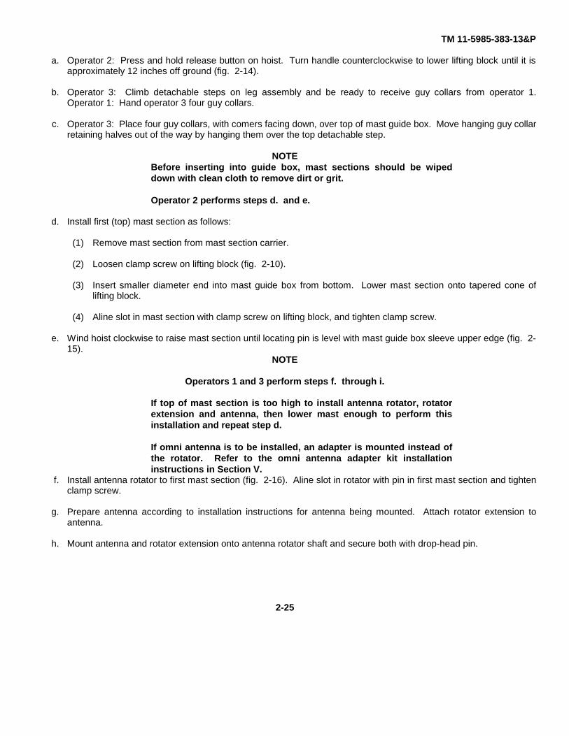
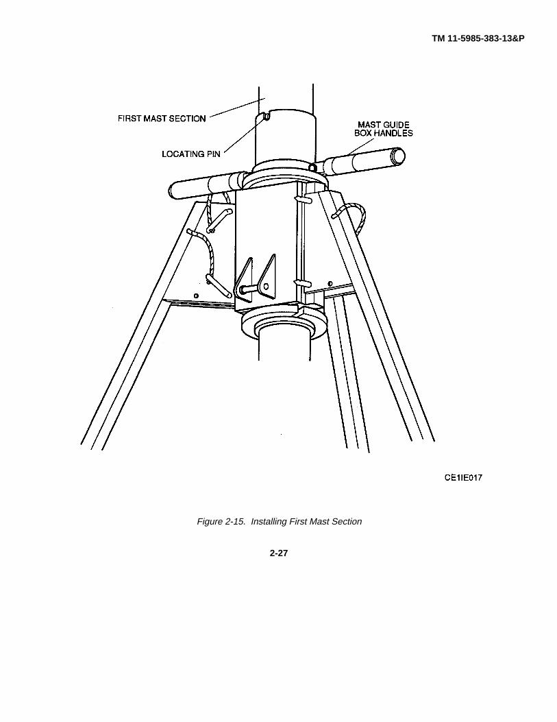
e. Wind hoist clockwise to raise mast section until locating pin is level with mast guide box sleeve upper edge (fig. 2-15).
NOTE
Operators 1 and 3 perform steps f. through i.
If top of mast section is too high to install antenna rotator, rotatorextension and antenna, then lower mast enough to perform thisinstallation and repeat step d.
If omni antenna is to be installed, an adapter is mounted instead ofthe rotator. Refer to the omni antenna adapter kit installationinstructions in Section V.
f. Install antenna rotator to first mast section (fig. 2-16). Aline slot in rotator with pin in first mast section and tightenclamp screw.
g. Prepare antenna according to installation instructions for antenna being mounted. Attach rotator extension toantenna.
h. Mount antenna and rotator extension onto antenna rotator shaft and secure both with drop-head pin.
2-25

TM 11-5985-383-13&P
Figure 2-14.Preparing Guy Collars for Installation
2-26
TM 11-5985-383-13&P
Figure 2-15. Installing First Mast Section
2-27

TM 11-5985-383-13&P
Figure 2-16. Antenna Rotator Installation
2-28

TM 11-5985-383-13&P
i. With antenna facing azimuth of target, the two ball stops on the ball rope should be same distance from rotatorassembly. If not, loosen antenna clamp, move ball rope without moving antenna, and tighten clamp.
NOTE
Operator 2 performs steps j. through I.
j. Fully raise first mast section with antenna. Aline hole of mast section with cutout in upper edge of mast guide box(fig. 2-15). Insert pin through cutout and holes in mast section. Disengage hoist handle. Press and hold releasebutton on hoist until support pin is seated properly in cutout of mast guide box. Continue to use this procedure forevery new section added. Loosen clamp screw on lifting block (fig. 2-10).
NOTE
It may be necessary to rotate mast guide box slightly to ensure holein mast section lines up with cutout in upper edge of mast guidebox.
k. Press and hold release button on hoist and at same time turn hoist handle counterclockwise. Lower lifting blockuntil it is approximately 12 inches off ground.
I. Insert second mast section into bottom of first mast section. Aline pin in second mast section with cutout inbottom of first mast section. Lower mast section onto lifting block and tighten clamp screw.
NOTE
Each time a mast section is placed on the lifting block, make sure itis secured by tightening clamp screw.
m. Raise two mast sections approximately 12 inches. Have operator 3 remove support pin and attach first guy collarto first mast section as follows (fig. 2-17):
(1) Raise guy collar plate above support pin hole.
(2) Fit the center pin of each guy collar retaining half into support pin holes in mast section.
(3) Slide guy collar plate down over guy collar halves to secure.
NOTE
As mast sections are installed, feeder cable straps must also beinstalled on the mast. Refer to antenna installation instructions inshelter technical manual for feeder cable strap installation.
To obtain desired antenna cable length use antenna cableextensions.
n. Operator 1: Unravel three guy extension cables from guy extension rings and hand one end of extension tooperator 3. Attach other end of guy extensions to guy cables of winch kit No. 1. Secure guy extension rings.
2-29

TM 11-5985-383-13&P
Figure 2-17. Installing First Guy Collar and Second Mast Section
2-30

TM 11-5985-383-13&P
NOTE
Six guy extensions are used on the first and second (upper two)guy collars. As mast is erected, guy collars are attached to mastsections as shown in figure 2-18. Arrowheads (1 through 4) identifythe guy cable paths after proper installation.
o. Operator 3: Attach guy extensions to first guy collar using snaphooks. Clip snap hook with pushbutton facingtowards the ground.
NOTE
It is recommended that protective gloves be worn by personnelwhen working on guy cables.
Operator 1 perform steps p. through s.
Operators 1 and 3 must follow directions from operator 2 tofacilitate mast erection.
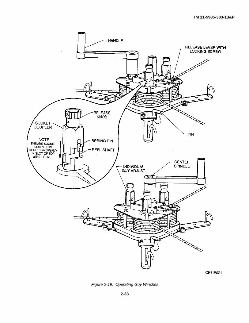
p. Lock all three drums on winch kit No. 1 by turning release knob counterclockwise (fig. 2-19). Check that springpin engages slot in socket coupler, and that socket coupler is seated properly in slot of top winch plate (refer tofigure 2-19).
WARNING
Whenever handle is removed from the center spindle to adjustindividual guy, ensure handle is returned to center spindle. Failureto do so could cause personal injury.
q. Adjust each guy using handle on individual guy adjust. Return handle to center spindle after each guy is adjustedand begin applying maximum tension.
WARNING
Never operate release lever without keeping load or tension on allthree guys, by holding winch handle (center spindle). Failure to doso could result in wrist and/or hand injury.
r. As mast is extended, release guys as needed by moving release lever to the left while applying maximum backpressure with handle in center spindle (turning counterclockwise). When lever is released, guy winch kit is locked.
s. Check that there is enough slack in antenna feed cable for antenna rotator to turn 1800 in either direction withoutstraining cable. Check that there is enough slack for cable to pass over guy collars and enable total mast to rotate180° in either direction without straining antenna cable against a guy cable.
NOTE
Operator 3 performs steps t. and u. only if a second antenna is tobe mounted on the mast.
2-31

TM 11-5985-383-13&P
Figure 2-18. Guy Installation
2-32
TM 11-5985-383-13&P
Figure 2-19. Operating Guy Winches
2-33

TM 11-5985-383-13&P
t. Continue installing mast sections until third section is installed. Connect side mounting adapter to thissection (fig. 2-20) covering support pin hole and secure with tee handle. Adapter is nowapproximately 8 feet below top guy collar.
Figure 2-20. Side Mounting Adapter
u. Mount second antenna on side mounting adapter according to installation instructions for antennabeing mounted.
NOTE
If an antenna is mounted on the side mounting adapter, there mustbe enough slack in antenna feed cable to enable mast to rotate 1800in either direction without straining antenna cable.
v. Operator 3: Hand operator 2 mast sections from mast carrier. Continue installing mast sections until the seventhsection is installed. At seventh section (fig. 2-18), install second guy collar as in step m.
2-34

TM 11-5985-383-13&P
w. Operator 1: From winch kit No. 2 (fig. 2-2), pull pulley block to middle stake and clip to top hole of stake.
x. Operator 1: Unravel three guy extension cables from guy extension rings and hand one end of extension tooperator 3. Attach other end of guy extension to guy cables of winch kit No. 2. Secure guy extension rings.
y. Operator 3: Attach guy extensions to second guy collar using snaphooks. Clip snaphook with pushbutton facingtowards the ground.
z. Lock all three drums on winch kit No. 2 by turning release knob counterclockwise (fig. 2-19). Check that springpin engages slot in socket coupler, and the socket coupler is seated properly in slot of top winch plate. Wind inany slack by using individual spindles.
WARNING
To prevent injury, an operator must keep a hand on the guy winchhandle at all times to prevent slipping.
Whenever handle is removed from the center spindle to adjustindividual guy, ensure handle is returned to center spindle. Failureto do this could cause personal injury.
It is important to maintain maximum tension in winch kits No. 1 andNo. 3 at all times during erection/retraction procedures. In order toachieve maximum tension, kneel with one hand on the winchassembly, and apply maximum hand effort to winch handle in astraight pulling motion.
aa. Operator 1: Man winch kits No. 1 and No. 2. As mast is extended, release guys from winch kits No.1 and No. 2as needed, by moving release lever counterclockwise while applying back pressure with handle in center spindle(turning counterclockwise). When lever is released, guy winch kit is locked. Prevent release lever from movingwith locking screw.
ab. Check that the mast is straight, and ensure that all guys from winch kits No. 1 and No. 2 have maximum tensionapplied. If mast is not straight, release the guys by moving winch release lever counterclockwise while applyingback pressure with handle in center spindle. Turn handle counterclockwise to release the desired amount of cable(maximum of one full turn). Lock winch by moving release lever clockwise. Adjust individual guys as needed.Return handle to center spindle after individual guys are adjusted. Repeat steps as required. Lock down releaselever with locking screw when adjustments are complete.
ac. Operator 3: Hand operator 2 additional mast sections. Continue installing mast sections until the thirteenth sectionis installed. At thirteenth section (fig. 2-18), install third guy collar as in step m.
ad. Operator 1: From winch kit No. 3 (fig. 2-2), pull pulley block to middle stake and clip to hole closest to the groundon stake. Hand end of guy cable to operator 3.
ae. Operator 3: Attach guy to third guy collar using snaphooks. Clip snaphook with pushbutton facing towards theground.
af. Operator 1: Lock all three drums on winch kit No. 3 by turning release knob counterclockwise (fig. 2-19). Checkthat spring pin engages slot in socket coupler, and that socket coupler is seated properly in slot of top winch plate.Wind in any slack using individual spindles.
2-35
TM 11-5985-383-13&P
NOTE
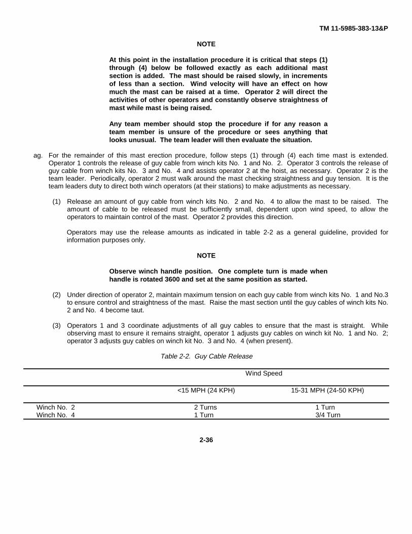
At this point in the installation procedure it is critical that steps (1)through (4) below be followed exactly as each additional mastsection is added. The mast should be raised slowly, in incrementsof less than a section. Wind velocity will have an effect on howmuch the mast can be raised at a time. Operator 2 will direct theactivities of other operators and constantly observe straightness ofmast while mast is being raised.
Any team member should stop the procedure if for any reason ateam member is unsure of the procedure or sees anything thatlooks unusual. The team leader will then evaluate the situation.
ag. For the remainder of this mast erection procedure, follow steps (1) through (4) each time mast is extended.Operator 1 controls the release of guy cable from winch kits No. 1 and No. 2. Operator 3 controls the release ofguy cable from winch kits No. 3 and No. 4 and assists operator 2 at the hoist, as necessary. Operator 2 is theteam leader. Periodically, operator 2 must walk around the mast checking straightness and guy tension. It is theteam leaders duty to direct both winch operators (at their stations) to make adjustments as necessary.
(1) Release an amount of guy cable from winch kits No. 2 and No. 4 to allow the mast to be raised. Theamount of cable to be released must be sufficiently small, dependent upon wind speed, to allow theoperators to maintain control of the mast. Operator 2 provides this direction.
Operators may use the release amounts as indicated in table 2-2 as a general guideline, provided forinformation purposes only.
NOTE
Observe winch handle position. One complete turn is made whenhandle is rotated 3600 and set at the same position as started.
(2) Under direction of operator 2, maintain maximum tension on each guy cable from winch kits No. 1 and No.3to ensure control and straightness of the mast. Raise the mast section until the guy cables of winch kits No.2 and No. 4 become taut.
(3) Operators 1 and 3 coordinate adjustments of all guy cables to ensure that the mast is straight. Whileobserving mast to ensure it remains straight, operator 1 adjusts guy cables on winch kit No. 1 and No. 2;operator 3 adjusts guy cables on winch kit No. 3 and No. 4 (when present).
Table 2-2. Guy Cable Release
Wind Speed
<15 MPH (24 KPH) 15-31 MPH (24-50 KPH)
Winch No. 2 2 Turns 1 TurnWinch No. 4 1 Turn 3/4 Turn
2-36

TM 11-5985-383-13&P
(4) Repeat steps (1) through (3) until section is raised completely. Continue with step ah.
ah. Operator 3: Hand operator 2 more mast sections. Continue installing mast sections following steps (1) through(4) above until the nineteenth section is installed. At nineteenth section (fig. 2-18), install fourth guy collar as instep m. Continue with step ai.
ai. Operator 1: From winch kit No. 4 (fig. 2-2), pull pulley block to stake closest tripod and clip to hole closest to theground on stake. Hand end of guy cable to operator 3.
aj. Operator 3: Attach guy to fourth guy collar using snaphooks. Clip snaphook with pushbutton facing towards theground.
ak. Operator 1: Lock all three drums on winch kit No. 4 by turning release knob counterclockwise (fig. 2-19). Checkthat spring pin engages slot in socket coupler, and that socket coupler is seated properly in slot of top winch plate.Wind in any slack using individual spindles.
al. Operator 3: Hand operator 2 more mast sections. Continue installing mast sections following steps (1) through(4) above, until mast is erected to desired height.
am. Once the mast is erect and straight, achieve the desired level of guy tension by kneeling with one hand on thewinch assembly, and apply maximum hand effort to winch handle in a straight pulling motion.
CAUTION
When tightening clamp, ensure cable is seated properly betweenthe grooves of the clamp. Do not allow groove edges to pinch theguy cable.
Hand tighten clamp until no more force can be applied. Do not usea tool or piece of equipment. Damage to equipment may occur.
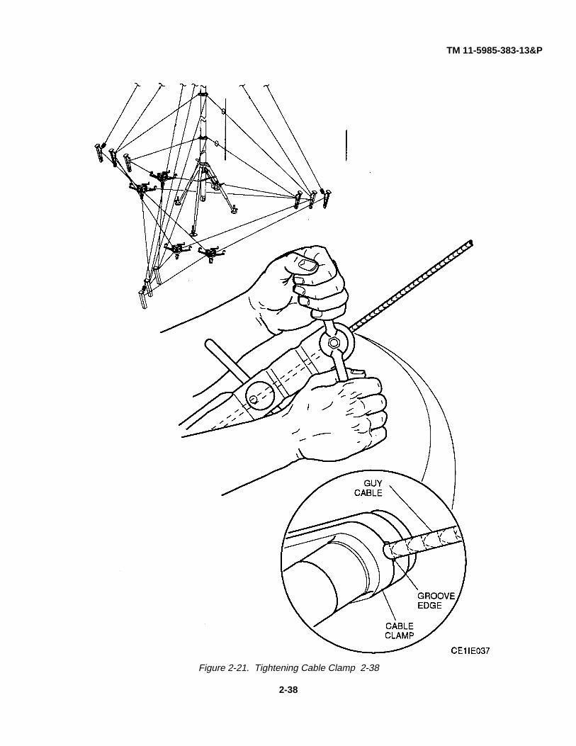
an. Secure cable clamp to guy cable (fig. 2-21). Ensure cable clamp is completely open. Seat clamp over guy cable.Ensure cable is seated properly between the grooves of the clamp. Tighten clamp.
ao. Lock all winch kits with locking screw on release lever (fig. 2-19).
ap. Operator 1: Secure ball rope to bottom of mast when not in use to prevent rope from flapping in wind.
WARNING
After completing mast installation, mark all guys with streamers orapproved markers in accordance with TB 43-0129. Failure to markguys could result in serious injury to personnel.
2-10 FINAL CHECKS.
After fully erecting mast, perform the following checks before leaving the area.
a. Check that tripod feet are firmly settled and spikes are fully implanted.
b. Check that all four winch kits are locked and spikes are fully implanted.
c. Check that all guy stakes have not moved from original position in ground.
2-37
TM 11-5985-383-13&P
Figure 2-21. Tightening Cable Clamp 2-38
2-38
TM 11-5985-383-13&P
d. Check that all guy cables are taut.
e. Check that mast is straight. If mast is leaning in any direction perform following steps:
CAUTION
Hand loosen clamp. Do not use a tool or piece of equipment toloosen clamp handle. Damage to equipment may occur.
NOTE
At winch kit No. 1, maximum tension should always be maintained.In order to achieve maximum tension, kneel with one hand on thewinch assembly, and apply maximum hand effort to winch handle ina straight pulling motion.
(1) Loosen cable clamp; release slowly to equalize tension on guy cable. Ensure cable clamp is completelyopen. Swing cable clamp away from guy and adjust winch kit No. 1 to maintain control of guy.
(2) Operators 1 and 3: Straighten mast using winch kits, working from bottom level upwards. Check that mastis vertically straight. Observe from position immediately under mast.
CAUTION
When tightening clamp, ensure cable is seated properly betweenthe grooves of the clamp. Do not allow the groove edges to pinchthe guy cable Hand tighten clamp until no more force can beapplied. Do not use a tool or piece of equipment. Damage toequipment may occur.
NOTE
Mast guys are to be tensioned as a part of the final adjustmentprocedure. Once the mast is erect and straight, in order to achievethe desired level of tension, kneel with one hand on the winchassembly, and apply maximum hand effort to winch handle in astraight pulling motion.
Progressive small adjustments are better than coarse adjustments.Stake points should be sound and release levers on all winchesshould be locked.
(3) After all guy cable adjustments have been made, secure cable clamp to guy cable (fig. 2-21). Ensure cableclamp is completely open. Seat clamp over guy cable. Ensure cable is seated properly between the groovesof the clamp. Tighten clamp.
(4) Lock winch kits with locking screw on release lever (fig. 2-19).
2-39

TM 11-5985-383-13&P
NOTE
Operator 1 performs steps (5) and (6).
(5) Erected mast can be rotated by side handles on guide box. Rotation is locked or unlocked using clamplever (fig. 2-22).
(6) With mast fully erected, refer to antenna installation instructions in appropriate technical manual for antennaalinement.
Section IV. PREPARATION FOR MOVEMENT
2-11 EQUIPMENT DISASSEMBLY.
WARNING
Do not disassemble mast if wind velocity is 30 mph or greater. Mastcould topple and cause serious injury or death to personnel.
During electrical storms or at any time there is a possibility oflightning strike, personnel must not attempt to erect, retract, oroperate the mast and must remain outside of the guy wire pickets.Serious injury or death could result from electrical shock due to arc-over from the mast. The presence of a ground rod, while it maysomewhat reduce the probability of such an arcover, does noteliminate the hazard.
NOTE
A team of three qualified personnel are required to lower anddisassemble the 30-meter mast as directed by operator 2. Refer toparagraph 2-8 for team duties.
Any team member should stop the procedure if for any reason ateam member is unsure of the procedure or sees anything thatlooks unusual. The team leader will then evaluate the situation.
a. Operators 1 and 3: Check the area and clear away any obstacles that may interfere with retraction procedures.
CAUTION
Hand loosen cable clamps. Do not use a tool or piece of equipmentto loosen clamp handles. Damage to equipment may occur.
b. Operator 1: At winch kit No.1 ensure maximum tension is applied to guys before cable clamps are released.
2-40

TM 11-5985-383-13&P
Figure 2-22. Mast Alinement
2-41
TM 11-5985-383-13&P
c. Operator 1: Loosen cable clamp, release slowly to equalize tension on guy cable . Ensure cable clamp iscompletely open. Swing cable clamp away from guy cable and adjust winch kit No.1 to maintain control.
WARNING
When lowering mast, ensure that lifting block is ALWAYS LOCKEDSECURELY within mast section. Failure to do this could result inserious injury to personnel.
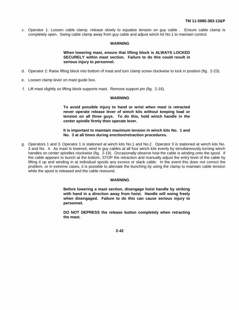
d. Operator 2: Raise lifting block into bottom of mast and turn clamp screw clockwise to lock in position (fig. 2-23).
e. Loosen clamp lever on mast guide box.
f. Lift mast slightly so lifting block supports mast. Remove support pin (fig. 2-16).
WARNING
To avoid possible injury to hand or wrist when mast is retractednever operate release lever of winch kits without keeping load ortension on all three guys. To do this, hold winch handle in thecenter spindle firmly then operate lever.
It is important to maintain maximum tension in winch kits No. 1 andNo. 3 at all times during erection/retraction procedures.
g. Operators 1 and 3: Operator 1 is stationed at winch kits No.1 and No.2. Operator 3 is stationed at winch kits No.3 and No. 4. As mast is lowered, wind in guy cables at all four winch kits evenly by simultaneously turning winchhandles on center spindles clockwise (fig. 2-19). Occasionally observe how the cable is winding onto the spool. Ifthe cable appears to bunch at the bottom, STOP the retraction and manually adjust the entry level of the cable bylifting it up and winding in at individual spools any excess or slack cable. In the event this does not correct theproblem, or in extreme cases, it is possible to alleviate the bunching by using the clamp to maintain cable tensionwhile the spool is released and the cable rewound.
WARNING
Before lowering a mast section, disengage hoist handle by strikingwith hand in a direction away from hoist. Handle will swing freelywhen disengaged. Failure to do this can cause serious injury topersonnel.
DO NOT DEPRESS the release button completely when retractingthe mast.
2-42

TM 11-5985-383-13&P
Figure 2-23. Lifting Block Positioning
WARNING
The release button on the hoist operates a brake mechanism thatallows controlled retraction of the mast. Depress the buttongradually and only enough to lower the mast slowly whilemaintaining a positive braking action. Depressing the buttoncompletely will disengage the brake resulting in a rapid lowering ofthe mast, which, in most cases, will be too fast for the winchoperators to wind in cable. The result could be complete loss ofcontrol and a mast collapse.
h. Operator 2 (team leader): Disengage hoist handle by gradually pressing release button on hoist (fig. 2-8) andlower mast until support pin can be put through next section. Continue lowering mast until section clears mastguide box. Remove section.
i. For the remainder of the mast retraction procedure, adjust guy cables as necessary to maintain mast in a verticalposition. If mast is not in a vertical position, perform steps (1) through (3). Repeat steps as necessary.
(1) All operators man their positions.
2-43
TM 11-5985-383-13&P
(2) Straighten mast using winch kits, working from bottom level upwards. Adjust winch kits to maintain verticalposition by winding drums individually so that all guy cables are at maximum tension.
(3) Check that mast is vertically straight. If guy cable needs to be released from winch, turn thumbscrewcounterclockwise on release lever. Move release lever to left while applying back pressure using handle incenter spindle. Turn handle counterclockwise, allowing enough slack to release guy cable. Secure releaselever by turning thumbscrew clockwise. At this time adjust winch kit by winding drums individually tomaintain mast in a vertical position.
j. Operator 2: Remove antenna feed cable straps from mast sections as they appear.
k. Operator 3: As mast sections are lowered, and only after attending winch kit activities, wind up slack on ball ropeand ensure rope does not interfere with retraction procedures.
I. Operator 3: At 19th mast section (fourth guy collar), unclasp three guy extension cables. Disconnect guy collarretaining halves from mast section. Move hanging guy collar retaining halves out of the way hanging them overthe top detachable step. Continue to do this for each guy collar disconnected.
m. Continue to lower mast. As mast sections are disengaged, remove each section from area of operation.
n. Operator 3: At 13th mast section (third guy collar), unclasp three guy collar snaps. Disconnect guy collar retaininghalves from mast section.
o. Operator 3: Unclasp pulley blocks from stakes. At winch kit No. 3 and No. 4 unlock drums on winch kit byturning release knob clockwise. Check that spring pin disengages socket coupler. Wind guys, manually guidingcable onto spool. Do not allow cable to bunch up at base of spool. Ensure that pulley block does not snag any ofthe guy cables still supporting the mast.
p. Continue to lower mast.
q. Operator 3: At seventh mast section (second guy collar), unclasp three guy collar snaps. Disconnect guy collarretaining halves from mast section.
r. Operator 3: Unclasp pulley blocks from stakes. At winch kit No. 2 unlock drums on winch kit by turning releaseknob clockwise. Check that spring pin disengages socket coupler. Wind guys, manually guiding cable onto spooldo not allow cable to bunch up at base of spool. Ensure that pulley block does not snag any of the guy cables stillsupporting the mast.
s. Continue to lower mast.
t. Operator 1 and 3: Disconnect guy cables from guy extensions.
u. Operator 3: When mast section containing antenna side mounting adapter is lowered, remove antenna (ifapplicable) from adapter according to instructions for antenna being removed. Hand antenna to operator 1 tosecure.
v. Remove side mounting adapter (if applicable) by loosening tee handle (fig. 2-20). Hand antenna adapter tooperator 1 to secure.
w. Continue to lower mast.
x. Operator 3: At first mast section (first guy collar), unclasp three guy collar snaps. Disconnect guy collar retaininghalves from mast section.
y. Operators 1 and 3: Disconnect guy cables from guy extensions.
2-44

TM 11-5985-383-13&P
z. Remove cable clamp from pulley block, unclasp retainer clip, and remove pulley pin. Once cable clamp isremoved, return pulley pin to pulley block and secure with retainer clip.
aa. Unclasp pulley blocks from stakes on winch kit No.1. Wind up guy extensions and secure. Unlock drums onwinch kit by turning release knob clockwise. Check that spring pin disengages socket coupler. Wind up guys,manually guiding cable onto spool. Do not allow cable to bunch up at base of spool.
ab. Operator 2: Lower mast section until locating pin is level with mast guide box sleeve upper edge (fig. 2-15).
ac. Operator 3: Remove drop head pin from rotator extension (fig. 2-16). Remove antenna and rotator extensionfrom antenna rotator and hand to operator 1.
ad. Operator 1: Remove rotator extension from antenna and secure.
ae. Operator 3: Loosen screw and remove rotator from mast section and hand to operator 1 to secure.
af. Operator 2: Remove last mast section.
ag. Remove pins and spikes from winch kit spreaders (fig. 2-11).
ah. Remove stakes from ground.
NOTE
If mast is grounded, perform the following step aj. If mast is notgrounded, continue to step aj.
ai. At mast guide box, disconnect ground from ground stud. Remove grounding equipment, refer to FM 11-487-4 aj.Remove spikes from adjustable feet.
ak. Disconnect hoist cable from tripod leg. Loosen wing nut, remove cable from pulley, and remove lifting block (fig.2-10). Rewind cable into hoist.
al. Lift hoist off mast guide box and remove hoist support bar (fig. 2-9).
am. Remove detachable steps from tripod leg (fig. 2-8).
an. Lay tripod on its side and remove each leg assembly from mast guide box (fig. 2-4).
ao. Remove adjustable feet from leg assemblies by removing cross pin and pulling feet straight out (fig.
2-3)
ap. Slide inner leg into outer leg for each leg assembly and insert pins to keep inner leg from sliding out.
2-12 EQUIPMENT PACKUP.
Following complete disassembly of the mast equipment, pack the equipment in its appropriate bags and mast carryingcases (table 2-1 and fig. 2-1).
Store equipment in appropriate vehicle for moving. Check that all tools are cleaned and stored with equipment.
2-45

TM 11-5985-383-13&P
Section V. ANTENNA ADAPTER KIT 2-13 OMNI ANTENNA ADAPTER KIT.
The omni antenna adapter kit allows the omni antenna (01-2739630-1) to be used with the 30-meter mast. When theomni antenna is used with the 30-meter mast, additional instructions are required during normal erection and retractionprocedures. Table 2-3 is a parts list of all the items supplied in the omni antenna adapter kit. Assemble all items prior tostarting the instructions.
Table 2-3. Omni Antenna Adapter Kit Parts List
ITEM PARTNO NUMBER QUANTITY DESCRIPTION
1 03-2750613-1 1 Antenna Adapter Assembly
2 82-2750614-1 4 Guy Cord Stake
3 03-2750615-1 4 Guy Assembly
4 89-2750616-1 1 Locating Line
5 M55339/07-00029 1 Connector Adapter
6 09-2734023-2 1 Signal Cable Assembly
7 82-2735123-1 1 Tripod Stake
8 86-2750709-1 1 Storage Bag
2-13.1 Omni Antenna Adapter Kit Installation. The following instructions must be followed when the omni antenna is used:
NOTE
The following procedure is performed after the first mast section isinstalled and mast section locating pin hole is level with mast guidebox sleeve upper edge.
Operators 2 and 3 perform steps a. through i.
a. Position adapter kit, tripod stake on ground at center of tripod below mast guide box. Using sledge hammer insertstake into ground leaving enough stake exposed to attach locating line.
b. Attach locating line, connector ring to tripod stake. Operator 3, facing tripod leg furthest from winches, walklocating line straight out towards mast pickets (POSITION A, refer to figure 2-24).
c. Operator 3, pull locating line taut, position stake inside winder (fig. 2-24) and using sledge hammer provided,install stake into ground to beginning of attachment bracket d. Operator 2, at tripod center, detach locating linefrom tripod stake and walk it around mast tripod leg and then reattach to tripod stake as operator 3 walks locatingline to POSITION B (fig. 2-24) estimating by eye 90 degrees from previous stake.
2-46

TM 11-5985-383-13&P
Figure 2-24. Guy Wire Stake Locations
2-47

TM 11-5985-383-13&P
e. Operator 3, pull locating line taut, position stake inside winder and using sledge hammer provided, install stakeinto ground to beginning of attachment bracket.
f. Operators 2 and 3 continue using steps b. through e. and install remaining stakes in POSITIONS C and D.
g. Install antenna adapter assembly to first mast section (fig. 2-25). Aline slots in adapter with pin in first mastsection and tighten clamp screw.
h. At omni antenna, release antenna mast adapter clamp latch and strain relief clamp latch.
i. Mount omni antenna onto antenna adapter stub and engage latch on antenna mast adapter clamp to secureantenna.
j. Connect signal cable to antenna signal cable connector and place signal cable in cable strain relief clamp.Engage latch to secure signal cable (fig. 2-25). At other end of signal cable, using connector adapter, attachsignal cable provided in kit (P/N 09-2734023-2).
k. Rotate omni antenna until one of black flexible Ground Radial Assembly (GRA) cables alines with tripod legfurthest from winch locations (POSITION A, fig. 2-24).
NOTEBefore the guy assemblies are used, they must be completely unraveled and theguy assembly cleat slid to the very end of the cord.
Ensure guy cord attached to stake at position A alines with corresponding guy wirestakes before attaching snap hook.
I. Attach guy assembly snap hooks to black GRA cables (fig. 2-25) and corresponding pickets located at positionsA,B,C, and D. Snap hook at end of guy assembly with shock cord is to be attached to stake.
m. If more than one antenna is used, refer to antenna installation instructions in appropriate technical manual forantenna alinement.
n. Return to paragraph 2-9.4, step j., and continue mast erection procedures with one exception, as more antennasections are added, operator 3 will continue checking guy cords at stakes to ensure that guy cord(s) do notobstruct erection procedures.
2-13.2 Omni Antenna Adapter Kit Guy Assembly Installation. The following steps are performed after the 30-meter mast iserect and secured and all final checks have been completed.
a. At guy cord stakes (guy cord cleats), pull guy cord through cleat until cord between snap hook and cleat becomesstraight and is parallel to shock cord. Lock cord into guy cleat as shown in figure 2-26. After guy cord is lockedinto position, cord between snap hook and cleat may hang loose, this is normal. Guy assembly is designed toallow for shock cord to maintain proper tension.
b. Wind up any remaining cord on winder and set winder next to guy wire stake.
c. Stow any remaining adapter kit equipment in storage bag.
2-48

TM 11-5985-383-13&P
Figure 2-25. Omni Antenna and Adapter Assembly Installation
2-49

TM 11-5985-383-13&P
2-14 OMNI ANTENNA ADAPTER KIT DISASSEMBLY.
After the 30-meter mast has been retracted and the first mast section is in the mast guide box, use the followinginstructions when the omni antenna is used:
a. At omni antenna, disconnect guy assembly snap hooks from omni antenna black GRA cables (fig. 2-25).
b. At omni antenna guy cord stakes, unclasp snap hooks from stakes and clasp to guy winder (fig. 2-26).
c. Wind up remaining guy cord and stow guy assemblies.
d. Pull up guy cord stakes and stow.
e. At signal cable attached to signal cable adapter, disconnect signal cable and signal cable adapter and stow.
f. At omni antenna, release strain relief clamp latch and disconnect signal cable from antenna.
g. Release antenna mast adapter clamp and remove omni antenna.
h. Loosen clamp screw and remove omni antenna adapter assembly.
i. Stow all omni antenna adapter kit equipment in storage bag.
j. Return to 30-meter mast disassembly procedure paragraph 2-11, step af.
2-50

TM 11-5985-383-13&P
Figure 2-26. Guy Assembly Installation
2-51/(2-52 blank)

TM 11-5985-383-13&P
CHAPTER 3OPERATING INSTRUCTIONS
Section I. CONTROLS AND INDICATORS
3-1 DAMAGE FROM IMPROPER SETTINGS.
If side handles (para 3-3) are rotated in one direction too many times, antenna cables will wrap around mast and maybreak.
3-2 OPERATOR CONTROLS.
The three operator controls for operating the 30-meter mast are illustrated in figure 3-1 and described in table 3-1. Thereare no indicators associated with the 30-meter mast.
Table 3-1. Antenna Operating Controls
Key Control/Indicator Function
A1 Side handles Aims top antenna if only one antenna is usedAims lower antenna if two antennas are used
B Azimuth ring Used for setting azimuth reference point(s) for antenna(s)
C1 Ball rope Aims top antenna only
Section II. OPERATION UNDER USUAL CONDITIONS
3-3 SIDE HANDLES.
Side handles on mast guide box are used to rotate entire mast. Mast rotates in same direction side handles are turned.
3-4 AZIMUTH RING.
The azimuth ring on mast guide box is divided into 3600 units. The ring is rotated for setting reference point for antennaazimuth.
3-5 BALL ROPE.
A ball rope from antenna rotator at top of mast to ground is used to rotate top antenna. Pulling on either end of rope turnsantenna rotator in direction rope is pulled until stopped by ball.
3-1

TM 11-5985-383-13&P
Figure 3-1. Antenna Operating Controls
3-2

TM 11-5985-383-13&P
Section III. OPERATION UNDER UNUSUAL CONDITIONS
3-6 ENVIRONMENTAL EXTREMES
The properly erected mast is capable of operating under unusual conditions that may be encountered in environmentalextremes such as high wind and rain, which includes blowing of fine sand and dust particles in a 40 mph wind; prolongedexposure to salt fog in a salt laden atmosphere; exposure to fungus caused by high humidity and warm temperatures; andsnow and ice loading of 1/2 inch on any surface. Proper PMCS checks should be doubled under these conditions.
3-7 ANTENNA AIMING
Should an unusual condition cause an antenna to move on the mast use the following methods to correct the antenna aim.
3-7.1 Single Mounted Antenna. Observe 30 meter mast. Ensure that a single antenna is mounted on the very top of themast, note the direction the antenna is pointing and perform the following:
a. Observe azimuth ring and reference point to be used for maximum signal strength.
b. Use the ball rope to rotate antenna to desired direction.
3-7.2 Both Antennas Mounted. Observe 30 meter mast, note the direction the antennas are pointing and perform thefollowing:
a. Observe azimuth ring and reference point to be used for maximum signal strength.
b. Unlock clamp lever on mast guide box and use side handles to correct the direction for the side mounted antenna.
c. Once desired direction is obtained lock using the clamp lever.
d. Use the ball rope to rotate top antenna to desired direction.
WARNINGA change in ground conditions (i.e., heavy or prolonged rain) may cause stakes tobecome loose. It is essential to periodically inspect stake security. Perform PMCSchecks on stakes as stated in Chapter 4, table 4-1. Failure to ensure stake securitycould cause the mast to topple, resulting in serious injury or death to personnel.
3-3/(3-4 blank)

TM 11-5985-383-13&P
CHAPTER 4OPERATOR MAINTENANCE INSTRUCTIONS
Section I. TOOLS AND EQUIPMENT
4-1 TOOLS AND EQUIPMENT.
No tools or test equipment are authorized for use by the operator.
4-2 REPAIR PARTS.
No repair parts are authorized for operator’s maintenance.
Section II. PREVENTIVE MAINTENANCE CHECKS AND SERVICES (PMCS)
4-3 GENERAL.
NOTE
When performing PMCS or routine checks, observe all WARNINGS and CAUTIONSlisted at the beginning of this manual, at the appropriate place in the procedures,or on plates and decals attached on the equipment.
Operator preventive maintenance is the systematic care, servicing, and inspection of equipment. It can prevent theoccurrence of trouble, reduce downtime, and maintain equipment in serviceable condition. To be sure that the equipmentis always ready for a mission, do the scheduled PMCS procedure.
4-4. PMCS PROCEDURES.
4-4.1 Routine Checks. Routine checks such as cleaning, dusting, washing, checking for loose and chipped paint,checking for damaged or frayed cables, storing items not in use, covering unused receptacles, checking for completeness,and checking for loose nuts, bolts, and screws are not listed as PMCS. They are things that should be done anytime theyare needed.
4-4.2 Continuous Operation. If the 30-meter mast is in continuous operation, check and service those items that can bechecked and serviced without disturbing operation. Make the complete checks and services when the 30-meter mast isdisassembled.
4-4.3 Defects. Deficiencies that cannot be corrected must be reported to higher maintenance personnel. Records andreports of preventive maintenance must be made in accordance with procedures given in DA Pam 738-750.
4-4.4 Scheduling. PMCS must be done at the specified times if possible. If operational requirements prevent doingPMCS at the specified times, make the required checks and services at the first opportunity. During operation PMCS mustbe done regularly to help identify small problems before they become big problems. In addition, the specified checks andservices must be performed under the following special conditions.
4-4.4.1 Before Operation. Always keep in mind the CAUTIONS and WARNINGS. Perform Before (B) PMCS.
4-1

TM 11-5985-383-13&P
4-4.4.2 During Operation. Always keep in mind the CAUTIONS and WARNINGS. Perform During (D) PMCS.
4-4.4.3 After Operation. Be sure to perform After (A) PMCS.
4-4.5 PMCS Table. Table 4-1 contains the PMCS procedures. It indicates what items to check, when to check them, andhow to check them. Perform the PMCS procedures thoroughly and always observe WARNINGS and CAUTIONS.
4-4.5.1 ITEM NO. Column. The checks and services are listed in the order that they shall be accomplished. Use thisnumber for the TM number on DA Form 2404, Equipment Inspection and Maintenance Worksheet, to record results ofchecks and services.
4-4.5.2 INTERVAL Columns. The columns headed B, D, and A contain a mark in the appropriate column. This indicateswhen to perform the PMCS procedure.
4-4.5.3 ITEM TO BE INSPECTED Column. The items listed in this column indicate what part of the equipment is to bechecked.
4-4.5.4 PROCEDURES Column. This column indicates how to perform the check on the item listed in the ITEM TO BEINSPECTED column.
4-4.5.5 EQUIPMENT WILL BE REPORTED NOT READY/AVAILABLE IF: Column. This column contains criteria that willcause the equipment to be classified as not ready because of inability to perform its primary mission. This column will beleft blank if the associated equipment will not cause the 30-meter mast to be unusable.
NOTEChecks in INTERVAL column are to be performed in the order listed.
Table 4-1. Operator Preventive Maintenance Checks and Services
B = Before D = During A = After
EQUIPMENT WILL BEITEM INTERVAL ITEM TO BE REPORTED NOT READYNO. B D A INSPECTED PROCEDURES /AVAILABLE IF
1 • Mast antenna, Check mast for straightness from30-meter directly under mast. If mast is
leaning in any direction, adjustappropriate guy cables and checkthat they are taut
• • • Check guy cables. If any arebroken or have broken strands,report this to unit maintenance
• Make sure stakes are securely inground, especially after heavy orprolonged rain. If a stake is loose,hammer stake further into ground.If stake is still too loose, anchorassociated guy cable to astationary object, if possible
4-2

TM 11-5985-383-13&PTable 4-1. Operator Preventive Maintenance Checks and Services - Continued
EQUIPMENT WILL BEITEM INTERVAL ITEM TO BE REPORTED NOT READYNO. B D A INSPECTED PROCEDURES /AVAILABLE IF
Check that spikes at tripod feetand guy winch kits are fullyimplanted
Check hoist support bar issecured to tripod legs
Check security of shackles onstakes. Shackles should bescrewed in fully
Perform following steps on all fourguy winch kits:
(1) Pull one guy cable all theway out
(2) Examine entire length ofcable for wear or frayedstrands. If any part isdefective, replace winchkit
(3) With tension on guycable, wind cable backslowly onto drum in winchkit. Make sure cable windsproperly onto drum
(4) Perform steps (1) through(3) for other two guycables
2 Mast Guide Box Use a clean dry cloth to wipeinside mast guide box (fig. 4-1)
Apply a light coat of oil underazimuth ring assembly
Apply a light coat of oil on top ofbottom retaining ring halves
3 Hoist Apply a light coat of oil at base ofhandle assembly (fig. 4-2)
Apply a light coat of oil on releasebutton shaft
Apply a light coat of oil at needlebearing
4-3

TM 11-5985-383-13&P
Table 4-1. Operator Preventive Maintenance Checks and Services - Continued
EQUIPMENT WILL BEITEM INTERVAL ITEM TO BE REPORTED NOT READYNO. B D A INSPECTED PROCEDURES /AVAILABLE IF
4 Lifting Block Apply a light coat of oil to pulleybearing (fig. 4-3)
5 Guy Winch Kit Apply a light coat of oil to threadson release knob above socketcoupler, and also to bushingsbelow socket coupler (fig. 4-4)
Apply a light coat of oil to base ofhexagon sleeve
6 Pulley Block Lightly oil pulley pin and swivel(fig. 4-5)
7 Leg Assembly Use a clean, lightly oiled clothand wipe leveling screw on eachleg assembly (fig. 4-6)
8 Antenna Side Apply a light coat of oil toMounting hinge surfaces and teeAdapter handle shaft (fig. 4-7)
4-4

TM 11-5985-383-13&P
Figure 4-1. Mast Guide Box Lubrication
4-5

TM 11-5985-383-13&P
Figure 4-2. Hoist Lubrication
4-6

TM 11-5985-383-13&P
Figure 4-3. Lifting Block Lubrication
4-7

TM 11-5985-383-13&P
Figure 4-4. Guy Winch Kit Lubrication
4-8

TM 11-5985-383-13&P
Figure 4-6. Leg Assembly Lubrication
Figure 4-5. Pulley Block Lubrication
4-9

TM 11-5985-383-13&P
Figure 4-7. Antenna Side Mounting Adapter Lubrication
4-10

TM 11-5985-383-13&P
CHAPTER 5UNIT MAINTENANCE INSTRUCTIONS
Section I. REPAIR PARTS, SPECIAL TOOLS, AND SUPPORTEQUIPMENT
5-1 COMMON TOOLS AND EQUIPMENT.
Common tools and test equipment authorized for use by unit maintenance are listed in the Maintenance Allocation Chart(MAC), Appendix B.
5-2 SPECIAL TOOLS, TMDE AND SUPPORT EQUIPMENT.
Special tools; Test, Measurement and Diagnostic Equipment (TMDE); and support equipment authorized for use by unitmaintenance are listed in the Repair Parts and Special Tools List (RPSTL), Appendix F.
5-3 REPAIR PARTS.
Repair parts and accessories authorized for use by unit maintenance are listed in the Repair Parts and Special Tools List(RPSTL), Appendix F.
Section II. REPAINTING AND REFINISHING INSTRUCTIONS
CAUTIONBefore painting, carefully mask all unpainted surfaces, nameplates, decals, MWOinformation, and other markings.
5-4 PAINTS AND FINISHES.
The only type of paints or finishes authorized for use on 30-meter mast are those listed in TB 43-0118, Field Instructionsfor Painting and Preserving Electronics Command Equipment.
5-5 PAINTING INSTRUCTIONS.
Refer to TB 43-0118, Field Instructions for Painting and Preserving Electronics Command Equipment, for instructionsabout painting.
5-6 CAMOUFLAGE PAINTING.
Communications-electronic equipment systems requiring camouflage pattern painting and operating under controlledenvironmental conditions (air conditioned) shall be painted in accordance with the patterns prescribed in TB 43-0118, FieldInstructions for Painting and Preserving Electronics Command Equipment.
5-1

TM 11-5985-383-13&PSection III. PREVENTIVE MAINTENANCE CHECKS AND SERVICES (PMCS)
5-7 GENERAL.
NOTEWhen performing PMCS or routine checks, observe all WARNINGS and CAUTIONSlisted at the beginning of this manual, at the appropriate place in the procedures,or on plates and decals attached on the equipment.
Preventive maintenance is the systematic care, servicing, and inspection of equipment to prevent the occurrence oftrouble, to reduce downtime, and to maintain equipment in serviceable condition. To be sure that your equipment isalways ready for a mission, do the scheduled Preventive Maintenance Checks and Services (PMCS).
5-8 PMCS PROCEDURES.
5-8.1 Routine Checks. Routine checks such as cleaning, dusting, washing, checking for chipped paint, checking fordamaged or frayed cables, storing items not in use, covering unused receptacles, checking for completeness, andchecking for loose nuts, bolts, and screws are not listed as PMCS. These are tasks that should be done any time they areneeded.
5-8.2 Continuous Operation. If the 30-meter mast is kept in continuous operation, check and service only those items thatcan be checked and serviced without disturbing operation. Make the complete checks and services when the 30-metermast is disassembled.
5-8.3 Defects. Deficiencies that cannot be corrected must be reported to higher category maintenance personnel.Records and reports of preventive maintenance must be made in accordance with procedures given in DA Pam 738-750.
5-8.4 Scheduling. PMCS must be done at the specified times if possible. If operational requirements prevent doing aPMCS at the specified time, make the required checks and services at the first opportunity. During operation, PMCS mustbe done regularly to help spot small troubles before they become big problems.
NOTEThe PROCEDURES column in the PMCS charts instruct how to perform therequired checks and services. Carefully follow these instructions. If theequipment must be in operation all the time, check those items that can bechecked and serviced without disturbing operation. Make the complete checksand services when the equipment is disassembled.
5-8.5 PMCS Table. Table 5-1 contains the PMCS procedures. It indicates what items to check, when to check them, andhow to check them. Perform the PMCS procedures thoroughly and always keep in mind the WARNINGS and CAUTIONS.
5-8.5.1 ITEM NO. Column. The checks and services are listed in the order that you should do them. Use this number forthe TM number on DA Form 2404, Equipment Inspection and Maintenance Worksheet, to record results of checks andservices.
5-2

TM 11-5985-383-13&P
5-8.5.2 INTERVAL Columns. The columns headed W, M, Q, S, A, B, and H contain a mark in the appropriate column.This indicates when to perform the PMCS procedure.
5-8.5.3 ITEM TO BE INSPECTED Column. The items listed in this column indicate what part of the equipment is to bechecked.
5-8.5.4 PROCEDURES Column. This column indicates how to perform the checks on the items listed in the ITEMS TOBE INSPECTED column.
NOTEThe checks in the INTERVAL column are to be performed in the order listed.
Table 5-1. Unit Preventive Maintenance Checks and Services
W = Weekly Q = Quarterly A = AnnuallyM = Monthly S = Semiannually B = Biannually H = Hourly
ITEM INTERVAL ITEM TO BENO. W M Q S A B H INSPECTED PROCEDURES
1 • Mast Guide Box Use a clean dry cloth to wipe inside mast(fig. 4-1) guide box
Apply a light coat of oil under azimuth ringassembly
Apply a light coat of oil on top of bottomretaining ring halves
2 • Hoist (fig. 4-2) Apply a light coat of oil at base handleassembly
Apply a light coat of oil on release buttonshaft
Apply a light coat of oil at needle bearing3 • Lifting Block (fig. 4-3) Apply a light coat of oil to pulley bearing
4 • Guy Winch Kit Apply a light coat of oil to threads on(fig. 4-4) release knob above socket coupler, and also
to bushings below socket coupler
Apply a light coat of oil to base of hexagonsleeve
5 • Pulley Block (fig. 4-5) Lightly oil pulley pin and swivel
6 • Leg Assembly (fig. 4-6) Use a clean, lightly oiled cloth and wipeleveling screw on each leg assembly
5-3

TM 11-5985-383-13&P
Table 5-1. Unit Preventive Maintenance Checks and Services - Continued
ITEM INTERVAL ITEM TO BENO. W M Q S A B H INSPECTED PROCEDURES
7 • Antenna Side Apply a light coat of oil to hingeMounting Adapter surfaces and tee handle shaft(fig. 4-7)
8 • Clamp Apply a light coat of oil to clamp screws
Section IV. TROUBLESHOOTING PROCEDURES5-9 GENERAL.
The troubleshooting information (table 5-2) is based on audible and visual symptoms obtained from Built-In-TestEquipment (BITE) and rf loop test. The chart lists the common faults which you may find during the operation ormaintenance of the 30-meter mast. The chart gives the probable causes of a fault and the corrective actions to take tocure the fault.
Table 5-2. Troubleshooting
FAULT PROBABLE CAUSE CORRECTIVE ACTION
1. Top antenna not a. Antenna rotator moved on mast a. Re-aim antenna using ball ropeproperly directed
b. Mast turned in mast guide box b. Loosen mast using clamp lever on mast guidebox
c. Re-aim antenna and tighten mast to mastguide box with clamp lever
2. Lower antenna not Mast turned in mast guide box a. Loosen mast using clamp lever on mast guideproperly directed box
b. Re-aim antenna and tighten mast to mastguide box with clamp lever. Leave clamp leverin locked (up) position
Section V. UNIT MAINTENANCE FOR 30-METER MAST5-10 GENERAL.
This section contains unit maintenance procedures for assemblies of the 30-meter mast.
5-4
TM 11-5985-383-13&P
5-11 MAST SECTION.
a. Removal.
(1) The mast consists of 24 separate sections. To remove a mast section, refer to paragraph 2-11 to lowermast as required until defective section is removed.
(2) Place removed mast sections into mast section carriers.
b. Replacement. Refer to paragraph 2-9.3 for re-erecting the mast.
5-12 GUY WINCH KIT.
a. Removal.
(1) There are four guy winch kits providing cables to support the mast. To remove a defective guy winch kit,refer to paragraph 2-11. Lower mast as required until guy cables can be disconnected from either mast guycollar or guy extensions.
(2) Place removed mast sections into mast section carriers.
(3) With tension off guys, unclip pulley blocks on winch kit from associated stakes (fig. 2-18). Wind guys intowinch kit.
(4) Remove pins and spikes from winch kit and remove winch kit.
b. Replacement.
(1) Open spreaders on winch kit and insert pin in each spreader to keep from closing. Drive spikes throughspreader holes, fully into ground. Release three drums by turning release knobs clockwise.
(2) Refer to paragraph 2-9.3 to complete mast erection.
5-13 GUY EXTENSION.
a. Removal.
(1) There are six guy extensions used to support the upper part of the mast. To remove a defective guyextension, refer to paragraph 2-11. Lower mast as required until guy extension can be disconnected fromguy collar.
(2) Place removed mast sections into mast section carriers.
(3) Unclip other end of guy extension from guy cable and remove guy extension.
b. Replacement.
(1) Clip one end of guy extension to end of guy cable.
(2) Clip other end of guy extension to guy collar.
(3) Refer to paragraph 2-9.3 for re-erecting mast.
5-5

TM 11-5985-383-13&P
5-14 ANTENNA ROTATOR.
a. Removal.
(1) Refer to paragraph 2-11 to lower mast as required to remove antenna rotator.
(2) Place removed mast sections into mast section carriers.
b. Replacement. Refer to paragraph 2-9.3 for re-erecting mast.
5-15 ROTATOR EXTENSION ADAPTER.
a. Removal.
(1) Refer to paragraph 2-11 to lower mast as required to remove rotator extension adapter.
(2) Place removed mast sections into mast section carriers.
b. Replacement. Refer to paragraph 2-9.3 for re-erecting mast.
5-16 FEEDER CABLE STRAP.
a. Removal.
(1) There are six feeder cable straps on the mast. To remove a defective feeder cable strap, refer to paragraph2-11. Lower mast as required until feeder cable strap can be removed.
(2) Place removed mast sections into mast section carriers.
b. Replacement. Refer to paragraph 2-9.3 for re-erecting mast.
5-17 LIFTING BLOCK.
CAUTIONWhen removing lifting block, it must be supported before removing hoistcable. Otherwise, lifting block will fall to ground and may be damaged.
a. Removal.
(1) With lifting block supported, remove drop-head pin connecting end of hoist cable to mast guide box (fig. 2-9).
(2) Loosen wing-nut on cable guard and slide cable guard clear of pulley.
(3) Wind cable into hoist until lifting block is free.
b. Replacement. Refer to paragraph 2-9.1, steps I. through o. to replace lifting block.
5-6
TM 11-5985-383-13&P
5-18 HOIST.
NOTEIf hoist handle is defective, remove by tapping handle with hand to disengage frominput shaft (fig. 2-9). Reverse this procedure when replacing handle. If anotherpart of hoist is defective, continue with step a. to remove and replace hoist.
a. Removal.
(1) Refer to paragraph 5-17, step a. to remove lifting block.
(2) Lift hoist from mast guide box.
b. Replacement.
(1) Hook hoist on mast guide box.
(2) Refer to paragraph 2-9.2, steps I. through o. to replace hoist.
5-19 MAST GUIDE BOX.
a. Removal.
(1) Refer to paragraph 2-11, steps a. through an. to lower mast and disassemble tripod.
(2) Place removed mast sections into mast section carriers.
(3) Remove mast guide box.
b. Replacement.
(1) Refer to paragraph 2-9.2, steps b. through e. to replace mast guide box.
(2) Refer to paragraph 2-9.2, steps k. through q. to reassemble tripod.
(3) Refer to paragraph 2-9.4 for re-erecting mast.
5-20 LEG ASSEMBLY.
a. Removal.
(1) Three leg assemblies make up a tripod. To remove a defective leg assembly, refer to paragraph 2-11.Lower mast as required until last mast section is removed.
(2) Lay tripod on its side with defective leg assembly in the air.
(3) Remove two drop-head pins connecting leg assembly to mast guide box and remove leg assembly.
NOTEPerform step (4) only if defective leg assembly contains the four detachable steps.
5-7

TM 11-5985-383-13&P
(4) Remove two drophead pins on all four detachable steps (fig. 2-8) and remove defective leg assembly.
b. Replacement.
(1) Insert two drophead pins to secure leg assembly to mast guide box.
(2) Install detachable steps to leg assembly, if applicable.
(3) Stand tripod upright and perform paragraph 2-9.2, steps I. through q. to reassemble tripod.
(4) Refer to paragraph 2-9.4 for re-erecting mast.
5-21 GUY COLLAR.
a. Removal.
(1) There are four guy collars on the mast. To remove guy collar refer to paragraph 2-11. Lower mast asrequired until defective guy collar is removed.
(2) Place removed mast sections into mast section carriers.
b. Replacement. Refer to paragraph 2-9.4 for re-erecting mast.
5-22 ANTENNA SIDE MOUNTING ADAPTER.
a. Removal.
(1) Refer to paragraph 2-11 to lower mast as required until antenna side mounting adapter is removed.
(2) Place removed mast section into mast section carriers.
b. Replacement. Refer to paragraph 2-9.4 for re-erecting mast.
5-23 STAKE.
a. Removal.
(1) There are nine stakes used with guy cables to support the erected mast. To remove a stake, unlock drum on guywinch kit associated with defective stake.
(2) Connect handle to associated guy, adjust, and turn clockwise to provide slack on guy (fig. 2-19).
NOTEIf mast starts leaning when removing tension, all drums for that guy level shouldbe adjusted.
(3) When enough tension is removed from defective stake, unclip pulley block from stake and pull stake fromground.
b. Replacement.
(1) Using sledge hammer provided, drive stake into ground up to stake hole closest to the ground. Do not usesame hole, make new hole adjacent to one left by removed stake. To correctly implant stake, see notefollowing step t. in paragraph 2-9.2.
5-8

TM 11-5985-383-13&P(2) Attach pulley block to stake.
(3) Turn associated drum counterclockwise until guy cable is taut.
(4) Check that all guys are taut and the mast is straight.
5-24 SPIKE.a. Removal. Fifteen spikes are used to secure guy winch kits and tripod leg assemblies to ground. To remove
a defective spike, pull it from ground.
b. Replacement. Drive spike fully into ground with sledge hammer.
5-25 STEP ASSEMBLY.a. Removal. There are four detachable steps connected to one leg assembly. To remove a defective step, remove
drop-head pin securing step from leg assembly and remove step (fig. 2-8).
b. Replacement. Install detachable step to leg assembly and secure with drop-head pin.
5-26 HOIST SUPPORT BAR.a. Removal.
(1) Swing hoist away from hoist support bar while still hooked on mast guide box.
(2) Slide hoist support bar up and remove from leg assemblies.
b. Replacement.
(1) Slide hoist support bar over same two leg assemblies and allow to slide down.
(2) Allow hoist to pivot back and rest against pad in middle of hoist support bar.
5-27 PULLEY BLOCK SNAP HOOK.a. Removal.
(1) Trace the guy cable with the defective snap hook to the guy collar to which it is attached. Lower mastsections (para 2-11) until guy collar is at mast guide box. At this point guy cable tension associated with thispulley block is relieved and no longer supports the mast.
(2) Unclip snap hook from stake shackle.
(3) Remove cotter pin from snap hook and pulley block (fig. 5-1).
(4) Remove fork end pin, washer, and defective snap hook.
b. Replacement.
(1) Place fork end of pulley block over connector end of new snap hook.
(2) Insert fork end pin through fork end of pulley block and snaphook.
(3) Place washer over fork end pin and secure with cotter pin.
(4) Clip snap hook to shackle of appropriate stake.
5-9

TM 11-5985-383-13&P
Figure 5-1. Pulley Block Snap Hook Replacement
5-10

TM 11-5985-383-13&P
(5) Refer to paragraph 2-9.4 for re-erecting mast.
5-28 CABLE CLAMP.
a. Removal.
(1) To remove a defective cable clamp from the pulley block, ensure proper tension is on guy cable associatedwith cable clamp.
(2) At pulley block (fig. 5-2), loosen cable clamp, release slowly to equalize tension on guy cable and openclamp completely.
(3) Remove retainer clip, pulley pin, and cable clamp.
b. Replacement.
(1) Position cable clamp and insert pulley pin, then retainer clip.
CAUTION
When tightening clamp, ensure cable is seated properly between the grooves ofthe clamp. Do not allow groove edges to pinch the cable.
Hand tighten clamp until no more force can be applied. Do not use a tool or apiece of equipment. Damage to equipment may occur.
(2) Ensure cable clamp is completely open. Seat clamp over guy cable. Ensure cable is seated properlybetween the grooves of the clamp. Tighten clamp.
Section VI. UNIT MAINTENANCE FOR 30-METER MAST ANTENNA ADAPTER KIT 5-29 ANTENNA ADAPTERMAINTENANCE.
5-29.1 Nylon Washer. Cotter Pin. and Knob Assembly (Fig. 5-3).
a. Removal.
(1) At knob assembly, remove cotter pin.
(2) Remove knob assembly and nylon washer from mast collar by turning knob assembly counterclockwise.
b. Replacement.
(1) Insert nylon washer onto knob assembly.
(2) Install knob assembly with nylon washer onto mast collar.
(3) Insert cotter pin into drill hole at end of knob assembly and bend cotter pin ends to secure.
5-11
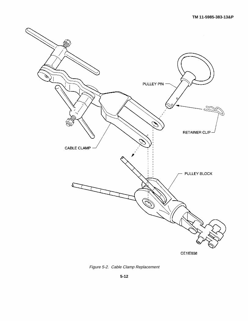
TM 11-5985-383-13&P
Figure 5-2. Cable Clamp Replacement
5-12
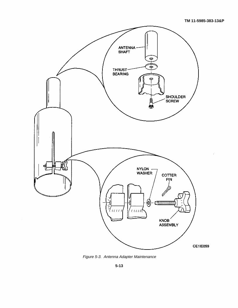
TM 11-5985-383-13&P
Figure 5-3. Antenna Adapter Maintenance
5-13

TM 11-5985-383-13&P
5-29.2 Antenna Shaft (Fig. 5-3).
a. Removal.
(1) With one hand, hold onto antenna shaft, and with the other hand, loosen shoulder screw.
(2) Remove shaft, thrust bearing and shoulder screw.
b. Replacement.
(1) Apply quick primer to threads of shoulder screw and antenna shaft.
(2) Apply sealing compound to threads of shoulder screw and antenna shaft.
(3) At mast collar from inside, insert shoulder screw.
(4) Install thrust bearing and antenna shaft onto shoulder screw. Ensure thrust bearing is flush with mast collar.
(5) With one hand, hold onto antenna shaft, and with the other hand, tighten shoulder screw by turningclockwise.
5-14

TM 11-5895-383-13&P
CHAPTER 6
DIRECT SUPPORT MAINTENANCE INSTRUCTIONS
Section I. GENERAL INFORMATION
6-1 INTRODUCTION.
This chapter provides instructions for direct support maintenance only. Direct support maintenance is performed by thosedesignated to support the using organization and emphasizes corrective action on items that are identified as faulty by unitpersonnel, but are beyond the unit maintenance resources authorized. Direct support maintenance is limited to theactivities described below.
6-1.1 Visual Inspection. Visually inspect components for evidence of potential failure conditions. Correction of observedconditions is to be accomplished as necessary at the time of observance by the maintenance level authorized to performthe task.
6-1.2 Removal and Replacement. Replace an unserviceable subassembly, module, assembly, or unit with a likesubassembly, module, assembly, or unit.
6-1.3 Repair. Perform the repairs required to correct a specific failure or unserviceable condition and restore an item to aserviceable condition.
Section II. TOOLS AND EQUIPMENT
6-2 TOOLS AND TEST EQUIPMENT.
Tools and test equipment required to perform the maintenance procedures given in this chapter are listed in theMaintenance Allocation Chart (MAC) in Appendix B. The test equipment listed in the table is authorized for use by directsupport maintenance personnel. Any tool or test equipment authorized for use at the unit level is also authorized for useby direct support.
6-3 REPAIR PARTS.
Repair parts and accessories authorized for use by direct support maintenance personnel for the 30-meter mast are listedin the Repair Parts and Special Tool List (RPSTL) in Appendix F.
Section III. REMOVAL AND REPLACEMENT PROCEDURES
6-4 GENERAL.
Corrective maintenance of the 30-meter mast at the direct support level is limited to the removal, repair, and replacementof the leg assembly, mast guide box, lifting block, antenna side mounting adapter, guy collar, picket location line, bubblelevel, rotator extension, mast section carrier, hoist support bar, step assembly, and mast section.
6-5 LEG ASSEMBLY REPAIR PROCEDURES.
Corrective maintenance of the 30-meter mast at the direct support level includes the removal and repair or replacement ofleg assembly parts. This and subsequent subparagraphs contain instructions for removal and replacement of these parts.
6-1

TM 11-5895-383-13&P6-5.1 Outer Leg Assembly Component Replacement Procedures. To remove and replace stop plates, inner leg, andouter leg corner gibs, proceed as follows (fig. 6-1):
a. Removal.
(1) Remove hex nuts and plain washers that secure top and bottom stop plates to outer leg. Remove stopplates.
(2) Note position of inner leg and withdraw inner leg from outer leg.
(3) Remove corner gibs from outer leg.
b. Replacement.
(1) Line up hole sides of inner and outer legs as noted in step (2) above, and slide inner leg into outer leg.
(2) Position corner gibs in outer leg (fig. 6-1).
(3) Replace stop plates and secure with plain washers and hex nuts.
6-5.2 Outer Leg Assembly Pins Replacement Procedures. To remove and replace leg pin assemblies and drop headpins, proceed as follows (fig. 6-1):
a. Removal.
(1) Untie knot on ∅4 Terylene cord that secures cord to leg assembly and slide cord out.
(2) Pull knotted end of cord at pin and remove cord out from pin.
b. Replacement.
(1) Cut replacement white, Terylene cord about 12 inches long and tie knot in one end.
(2) Insert other end through side of pin and slide pin to knot.
(3) Insert cord in hole in leg assembly. Tie knot at end to secure cord to leg.
6-5.3 Inner Leg Assembly Component Replacement Procedures. To remove and replace inner leg assembly slideangles, proceed as follows (fig. 6-1):
a. Removal.
(1) Remove inner leg from outer leg (para 6-5.1, step a).
(2) Remove hex screw that secures four slide angles to inner leg. Remove slide angles.
b. Replacement.
(1) Replace four slide angles on inner leg (fig. 6-1).
(2) Secure slide angles with hex head screw.
6-5.4 Inner Leg Assembly Foot Clip Replacement Procedures. To remove and replace assembly foot clip (fig. 6-1),proceed as follows:
a. Removal.
(1) Untie knot on 04 Terylene cord that secures cord to leg assembly foot clip and slide cord out.6-2

TM 11-5895-383-13&P
Figure 6-1. Leg Assembly Removal and Replacement
6-3

TM 11-5895-383-13&P
(2) Pull knotted end of cord at clip and remove cord from clip.
b. Replacement.
(1) Cut replacement white, Terylene cord about 12 inches long and tie knot in one end.
(2) Insert other end through side of clip and slide clip to knot.
(3) Insert cord in hole in leg assembly. Tie knot at end to secure cord to leg.
6-6 MAST GUIDE BOX REPAIR PROCEDURES.
Corrective maintenance of the 30-meter mast at the direct support level includes the removal and repair or replacement ofmast guide box parts. This and subsequent subparagraphs contain instructions for removal and replacement of theseparts.
6-6.1 Side Handle Replacement Procedures. To remove and replace side handle, proceed as follows (fig. 6-2):
a. Removal.
(1) Remove hex bolt, flat washer, and self lock nut (fig. 6-2, sheet 1) securing side handle assembly to mastguide sleeve.
(2) Remove handle assembly.
b. Replacement.
(1) Replace and secure side handle to mast guide sleeve with hex bolt, flat washer, and self lock nut.
6-6.2 Support Pin and Rope Replacement Procedures. To remove and replace support pin and support pin rope, proceedas follows (fig. 6-2):
a. Removal.
(1) Remove hex nut and ferrule (fig. 6-2, sheet 1) securing lower support pin rope to mast guide box.
(2) Remove stud.
(3) At other end of support pin rope, remove cap and shouldered bush from support pin.
(4) Remove support pin rope.
b. Replacement.
(1) Replace and secure shouldered bush on support pin.
(2) Replace and secure support pin rope on shouldered bush with cap.
(3) At other end of support pin rope, replace stud in mast guide box.
(4) Replace and secure support pin rope on stud with ferrule and hex nut.
6-6.3 Drop Head Pin Assembly and Cord Replacement Procedures. To remove and replace drop head pin and cord,proceed as follows (fig. 6-2):
6-4

TM 11-5895-383-13&P
Figure 6-2. Mast Guide Box Removal and Replacement (Sheet 1 of 4)
6-5
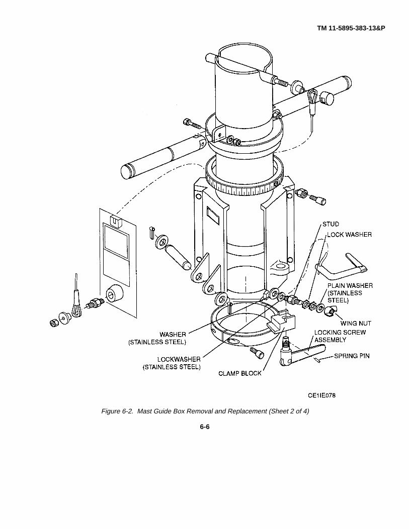
TM 11-5895-383-13&P
Figure 6-2. Mast Guide Box Removal and Replacement (Sheet 2 of 4)
6-6

TM 11-5895-383-13&P
Figure 6-2. Mast Guide Box Removal and Replacement (Sheet 3 of 4)
6-7

TM 11-5895-383-13&P
Figure 6-2. Mast Guide Box Removal and Replacement (Sheet 4 of 4)
6-8

TM 11-5895-383-13&Pa. Removal.
(1) Untie knot (fig. 6-2, sheet 3) securing cord and pin to mast guide box.
(2) Remove cord.
(3) At other end of cord, untie knot securing pin.
(4) Remove pin from cord.
b. Replacement.
(1) Cut replacement white, Terylene cord about 16 inches long and tie knot in one end of cord.
(2) Insert other end through hole in pin and slide pin to knot.
(3) Insert cord into cord hole in mast guide box and tie knot at end to secure cord to box.
6-6.4 Hoist Pin Replacement Procedures. To remove and replace hoist pin, proceed as follows (fig. 6-2):
a. Removal.
(1) Remove two split pins and flat washer (fig. 6-2, sheet 3) securing hoist pin to mast guide box.
(2) Remove hoist pin.
b. Replacement.
(1) Attach washer and split pin on one end of replacement hoist pin.
(2) Insert other end of replacement hoist pin through hoist pin holes in mast guide box.
(3) Secure hoist pin in place with second washer and split pin set.
6-6.5 Clamp Block Replacement Procedures. To remove and replace clamp block, proceed as follows (fig. 6-2):
a. Removal.
(1) Use a standard pin punch to remove spring pin (fig. 6-2, sheet 2) securing locking screw assembly to clampblock.
(2) Unscrew and remove locking screw assembly.
(3) Remove clamp block.
b. Replacement.
(1) Replace clamp block, aligning hole in clamp block with locking screw assembly holes. Ensure lip of clampblock fits over bottom retaining ring half.
(2) Insert and turn clockwise to tighten locking screw assembly.(3) Secure locking screw assembly in place with spring pin.
6-6.6 Locking Screw Assembly Replacement Procedures. To remove and replace locking screw assembly, proceed asfollows (fig. 6-2):
a. Removal.(1) Use a standard pin punch to remove spring pin (fig. 6-2, sheet 2) securing locking screw assembly to clamp
block.6-9

TM 11-5895-383-13&P
(2) Unscrew and remove locking screw assembly.
(3) Tap out connecting pin to separate locking screw arm from locking screw body.
b. Replacement.
(1) Replace locking screw arm in locking screw body.
(2) Tap connecting pin gently in place to secure locking screw arm to locking screw body.
(3) Insert and turn clockwise to tighten locking screw assembly.
(4) Secure locking screw assembly in place with spring pin.
6-6.7 Bottom Retaining Ring Half Replacement Procedures. To remove and replace bottom retaining ring half, proceedas follows (fig. 6-2):
a. Removal.
(1) Punch out and remove spring pin (fig. 6-2, sheet 2) securing locking screw assembly to clamp block.
(2) Unscrew and remove locking screw assembly.
(3) Remove clamp block.
(4) Remove socket head capscrews securing bottom retaining ring halves and remove retaining ring halves.
(5) Slide mast guide box down and remove guide box from mast guide sleeve.
(6) Unscrew two thumb screws on azimuth ring and remove azimuth ring from mast guide sleeve.
b. Replacement.
(1) Position and slide azimuth ring down mast guide sleeve until it comes to rest against side handle collar.
(2) Secure azimuth ring on mast guide sleeve by tightening two azimuth ring thumb screws.
(3) Position mast guide box on mast guide sleeve such that mast guide box abuts azimuth ring. Secure mastguide box with bottom retaining ring half.
(4) Tighten two screws that secure bottom retaining ring halves.
(5) Replace clamp block, aligning hole in clamp block with locking screw assembly holes. Ensure lip of clampblock fits over bottom retaining ring half.
(6) Insert and turn locking screw assembly clockwise to tighten.
(7) Secure locking screw assembly in place with spring pin.
6-7 LIFTING BLOCK REPAIR PROCEDURES.
Corrective maintenance of the 30-meter mast at the direct support level includes the removal and repair or replacement oflifting block parts. This and subsequent subparagraphs contain instructions for removal and replacement of these parts.
6-10

TM 11-5895-383-13&P
6-7.1 Lifting Block Component Replacement Procedures. To remove and replace lifting block component parts, proceedas follows (fig. 6-3):
a. Removal.
(1) Remove three screws that secure lead cone to lifting block body and remove lead cone.
(2) Remove clamp screw spring pin with standard punch and washers that secure clamp screw. Removeclamp screw.
(3) Partially unscrew clamp screw and remove second washer.
(4) Unscrew and remove clamp screw.
(5) Remove clamp segment.
NOTE
Clamp segment guide pin may hinder withdrawal of clamp segment.
(6) Use a standard pin punch and remove guide pin.
b. Replacement.
(1) Insert spring pin guide.
(2) Slide clamp segment into position on lifting block body, observing segment pin, which may hinder segmentreplacement.
(3) Insert and partially screw in clamp screw.
NOTE
Allow sufficient space at clamp screw protruding end for installing washer andspring pin.
(4) Slide washer onto clamp screw at clamp segment. Turn clamp screw until end of clamp screw protrudesfrom other side of bar and washer is flat against bar.
(5) Slide second washer onto protruding end of clamp screw.
(6) Insert spindle split pin into hole on protruding end of clamp screw. Tap pin gently until pin fits snugly intoplace, protruding from both ends of hole.
(7) Place lead cone in lifting block body. Align screw holes in cone with those in body, and secure with threescrews.
6-7.2 Pulley Assembly Replacement Procedures. To remove and replace lifting block pulley component parts, proceed asfollows (fig. 6-3):
a. Removal.
(1) Remove spindle split pin.
(2) Remove spindle washer and unscrew and remove spindle wing nut.
(3) Remove pulley guard.6-11

TM 11-5895-383-13&P
Figure 6-3. Lifting Block Removal and Replacement
6-12

TM 11-5895-383-13&P(4) Remove thin nut.
(5) Remove spindle and pulley.
(6) Remove two bronze bearings from pulley.
b. Replacement.
(1) Insert two replacement bronze bearings in pulley and align bearings with outer edges of pulley.
(2) Insert and align replacement pulley with holes in lifting block body.
(3) Insert spindle through lifting block body and pulley holes and secure with thin nut.
(4) Attach and secure pulley guard with wing nut.
(5) Secure washer with split pin.
6-8 ANTENNA SIDE MOUNTING ADAPTER REPAIR PROCEDURES.
Corrective maintenance of the 30-meter mast at the direct support level includes the removal and repair or replacement ofantenna side mounting parts. This and subsequent subparagraphs contain instructions for removal and replacement ofthese parts.
6-8.1 Tee Handle Replacement Procedures. To remove and replace antenna side mounting adapter tee handle, proceedas follows (fig. 6-4):
a. Removal.
(1) Turn tee handle fully clockwise to access spring pin.
(2) Remove spring pin.
(3) Remove washer.
(4) Turn tee handle counterclockwise and remove handle.
(5) Unscrew and remove tee handle stud.
(6) Unscrew and remove socket grub screw, and remove screwed bush.
b. Replacement.
(1) Insert screwed bush and secure with socket grub screw.
(2) Screw in tee handle stud.
(3) Replace and turn tee handle clockwise to secure handle. Allow sufficient room on handle end of stud toreplace spring pin.
(4) Replace washer, and secure washer and handle with spring pin.
6-8.2 Bracket Clamp Replacement Procedures. To remove and replace antenna side mounting adapter bracket clamp,proceed as follows (fig. 6-4):
a. Removal.
(1) Remove bracket clamp hinge pin split pin.6-13

TM 11-5895-383-13&P
Figure 6-4. Antenna Side Mounting Adapter Removal and Replacement
6-14
TM 11-5895-383-13&P
(2) Remove washer.
(3) Gently tap out and remove hinge pin.
(4) Remove bracket clamp.
b. Replacement.
(1) Replace and secure bracket clamp with bracket clamp hinge pin.
(2) Replace washer on hinge pin.
(3) Secure bracket clamp with hinge pin split pin.
6-9 GUY COLLAR REPAIR PROCEDURES.
Corrective maintenance of the 30-meter mast at the direct support level includes the removal and repair or replacement ofguy collar parts. This and subsequent subparagraphs contain instructions for removal and replacement of these parts.
6-9.1 Guy Collar Replacement Procedures. To remove and replace guy collar component parts, proceed as follows (fig.6-5):
a. Removal.
(1) Untie knot on cord at guy collar plate and slide cord out.
(2) At guy collar retaining half, pull cord out from knotted end.
(3) Unscrew and remove screw from guy collar retaining half.
b. Replacement.
(1) Replace and tighten screw in guy collar retaining half.
(2) Cut replacement white, Terylene cord about 26 inches long. Tie knot in one end.
(3) Insert other end of cord through inner side of guy collar retaining half screw.
(4) Insert cord in cord hole in guy collar plate from underneath side of plate. Tie knot at end of cord.
6-10 PICKET LOCATION LINE REPAIR PROCEDURES.
Corrective maintenance of the 30-meter mast at the direct support level includes the removal and repair or replacement ofpicket location line. This and subsequent subparagraphs contain instructions for removal and replacement of these parts.
6-10.1 Picket Location Line Replacement Procedures. To remove and replace picket location line component parts,proceed as follows (fig. 6-6):
a. Removal.
(1) Remove black sleeve securing rope to ring or spool.
(2) Remove black sleeve securing rope to second ring or spool.
(3) Repeat as required for additional sections of rings or spools.
6-15

TM 11-5895-383-13&P
Figure 6-5. Guy Collar Removal and Replacement
6-16

TM 11-5895-383-13&P
Figure 6-6. Picket Location Line Removal and Replacement
6-17
TM 11-5895-383-13&P
b. Replacement.
(1) Cut replacement white, Ulstron rope about 26 inches long.
(2) Secure one end of rope to ring or spool with black sleeve.
(3) Similarly secure other end of rope to second ring or spool.
(4) Repeat as required for additional sections of rings or spools.
6-11 BUBBLE LEVEL REPAIR PROCEDURES.
Corrective maintenance of the 30-meter mast at the direct support level includes the removal and repair or replacement ofbubble level parts. This and subsequent subparagraphs contain instructions for removal and replacement of these parts.
6-11.1 Level Extension Arm/Components Replacement Procedures. To remove and replace level extension arm andcomponent parts, proceed as follows (fig. 6-7):
a. Removal.
(1) Remove socket head capscrew from level block and remove level extension arm from block.
(2) Untie knot from level extension Arm and remove Ulstron cord from arm.
(3) Slide locating pin from cord.
b. Replacement.
(1) Cut replacement Ulstron cord about 10 inches long. Tie knot in one end.
(2) Insert other end of rope through hole in locating pin.
(3) Slide end of cord through holes in level extension arm. Tie knot in cord about one inch up from end,securing cord to arm.
(4) Replace level extension arm in level block.
(5) Replace and tighten socket head capscrew in level block.
6-11.2 Bubble Level Replacement Procedures. To remove and replace bubble level component parts, proceed as follows(fig. 6-7):
a. Removal.
(1) Remove pivot screw from circular bubble level cover on level block and remove flat washer and springwasher.
(2) Remove cover.
(3) Remove three cheese head screws from bubble level and remove bubble level.
b. Replacement.
(1) Replace and secure bubble level in level block with three cheese head screws.
(2) Replace and secure level cover to level block with flat washer, spring washer, and pivot screw.
6-18

TM 11-5895-383-13&P
Figure 6-7. Bubble Level Removal and Replacement
6-19

TM 11-5895-383-13&P
6-12 ROTATOR EXTENSION ADAPTER REPAIR PROCEDURES.
Corrective maintenance of the 30-meter mast at the direct support level includes the removal and repair or replacement ofrotator extension adapter parts. This and subsequent subparagraphs contain instructions for removal and replacement ofthese parts.
6-12.1 Rotator Extension Adapter Components Replacement Procedures. To remove and replace rotator extensionadapter component parts, proceed as follows (fig. 6-8):
a. Removal.
(1) Untie knot securing drop head pin to extension tube rope. Remove pin.
(2) Slide Ulstron rope out of tube.
b. Replacement.
(1) Cut replacement Ulstron rope about 10 inches long. Tie knot in one end.
(2) Insert other end of rope through holes in extension tube and hole in drop head pin.
(3) Tie knot at pin end of rope to secure pin.
6-13 MAST SECTION CARRIER REPAIR PROCEDURES.
Corrective maintenance of the 30-meter mast at the direct support level includes the removal and repair or replacement ofmast section carrier parts. This and subsequent subparagraphs contain instructions for removal and replacement of theseparts.
6-13.1 Mast Section Carrier Component Replacement Procedures. To remove and replace mast section carriercomponent parts, proceed as follows (fig. 6-9):
a. Removal.
(1) Unbuckle and remove mast section carrier strap from one end section.
(2) Remove strap from second end section, as necessary.
b. Replacement.
(1) Insert tip end of carrier strap through strap hole on one end of end section.
(2) Pull strap across top of end section, and insert strap tip in strap hole on other end of end section, from outerside of hole. Ensure that inner side of strap contacts top of end section.
(3) Repeat step b. (2) for second end section, as necessary, ensuring that end sections face out whencompleted (fig. 6-9).
6-14 HOIST SUPPORT BAR REPAIR PROCEDURES.
Corrective maintenance of the 30-meter mast at the direct support level includes the removal and repair or replacement ofhoist support bar parts. This and subsequent subparagraphs contain instructions for removal and replacement of theseparts.
6-14.1 Hoist Support Bar Component Replacement Procedures. To remove and replace hoist support bar componentparts, proceed as follows (fig. 6-10):
6-20

TM 11-5895-383-13&P
Figure 6-8. Rotator Extension Adapter Removal and Replacement
6-21

TM 11-5895-383-13&P
Figure 6-9. Mast Section Carrier Removal and Replacement
6-22

TM 11-5895-383-13&P
Figure 6-10. Hoist Support Bar Removal and Replacement
6-23

TM 11-5895-383-13&P
a. Removal.
(1) Remove two screws securing pad to hoist support bar.
(2) Remove pad and flat washers.
b. Replacement.
CAUTION
Be careful not to overtighten screws when replacing pad. Over tightening maydamage pad.
(1) Replace flat washers and screws in pad.
(2) Secure pad to hoist support bar with two screws.
6-15 STEP ASSEMBLY REPAIR PROCEDURES.
Corrective maintenance of the 30-meter mast at the direct support level includes the removal and repair or replacement ofstep assembly parts. This and subsequent subparagraphs contain instructions for removal and replacement of theseparts.
6-15.1 Step Assembly Component Replacement Procedures. To remove and replace step assembly component parts,proceed as follows (fig. 6-11):
a. Removal.
(1) Align drop head pin retainer with pin body and slide pin out of step.
(2) Untie knots securing Terylene cord to step and head pin.
b. Replacement.
(1) Select a piece of 04 white, Terylene cord about 11 inches long.
(2) Slip one end of cord through hole in drop head pin. Tie a knot at end of cord to secure pin.
(3) Slip other end of cord through hole in step. Tie a knot at end of cord to secure step.
6-16 MAST SECTION REPAIR PROCEDURES.
Corrective maintenance of the 30-meter mast at the direct support level includes the removal and repair or replacement ofmast section parts. This and subsequent subparagraphs contain instructions for removal and replacement of these parts.
6-16.1 Mast Section Component Replacement Procedures. To remove and replace mast section component parts,proceed as follows (fig. 6-12):
6-24

TM 11-5895-383-13&P
Figure 6-11. Step Assembly Removal and Replacement
6-25

TM 11-5895-383-13&P
Figure 6-12. Mast Section Removal and Replacement
6-26

TM 11-5895-383-13&P
a. Removal.
(1) Remove two retaining pins located inside mast section tube that secure locating pin in position.
(2) Remove locating pin.
b. Replacement.
(1) Insert one end of locating pin partly into hole in mast section tube and insert straight side of retaining pin inhole in locating pin. Clip retaining pin in place over locating pin.
(2) Slide locating pin fully against inside wall of tube nearest retaining pin.
(3) Insert straight side of second retaining pin in hole on other end of locating pin, and clip pin in place.
6-27/(6-28 blank)

TM 11-5985-383-13&PAPPENDIX A
REFERENCES
AR 55-38/NAVSUPINST 4610.33C/ Reporting Transportation Discrepancies in ShipmentsAFR 75-18/MCO P4610.19D/DLAR 4500.15
AR 735-11-2/DLAR 4140.55/ Reporting of Item and Packaging DiscrepanciesSECNAVINST 4355.18/AFR 400-54/MCO 4430.3J
DA Form 2404 Equipment Inspection and Maintenance Worksheet
DA Pam 738-750 The Army Maintenance Management System (TAMMS)
DA Pam 25-30 Consolidated Index of Army Publications and Blank Forms
FM 11-487-4 Installation Practices: Communications Systems Grounding,Bonding and Shielding
FM 21-11 First Aid for Soldiers
SF 361 Discrepancy in Shipment Report (DISREP): AR 55-38
SF 364 Report of Discrepancy (ROD)
SF 368 Product Quality Deficiency ReportTM 750-244-2 Procedures for Destruction of Electronic Material to Prevent
Enemy Use (Electronic Command)
TB 11-5800-216-15 Warranty Program for MSE
TB 43-0118 Field Instructions for Painting and Preserving ElectronicsCommand Equipment Including Camouflage PatternPainting of Electronic Equipment Shelters
TB 43-0129 Safety Measures to be Observed When Installing and UsingWhip Antennas, Field-Type Masts, Towers, Antennas andMetal Poles That Are Used With Communication, Radar, andDirection Finder Equipment
TM 11-5820-1029-13&P Operator’s, Unit, and Direct Support Maintenance ManualIncluding RPSTL Radio Set AN/GRC-226(V)1 and AN/GRC-226(V)2
TM 11-5820-1024-13 Operator’s, Unit, and Direct Support Maintenance ManualRadio Set AN/GRC-224
TM 11-5820-1023-13-1 Operator’s, Unit, and Direct Support Maintenance ManualLine-of-Sight Multichannel Radio Terminal AN/TRC-190
TM 11-5820-1022-13-1 Operators, Unit, and Direct Support Maintenance ManualRadio Access Unit AN/TRC-191A
A-1/(A-2 blank)
TM 11-5985-383-13&PAPPENDIX B
MAINTENANCE ALLOCATIONSection I. INTRODUCTION
B-1 GENERAL.This appendix provides for a summary of the maintenance operations for Mast, Antenna, 30-Meter AB-1340/G. Itauthorizes categories of maintenance and tools and equipment required to perform each function. This appendix can beused as an aid in planning maintenance operations.B-2 MAINTENANCE FUNCTION.Maintenance functions shall be limited to and defined as follows:
a. Inspect. To determine the serviceability of an item by comparing its physical, mechanical, and/or electricalcharacteristics with established standards through examination.
b. Test. To verify serviceability and to detect incipient failure by measuring the mechanical or electricalcharacteristics of an item and comparing those characteristics with prescribed standards.
c. Service. Operations required periodically to keep an item in proper operating condition, i.e., to clean, preserve,drain, paint, or to replenish fuel, lubricants, hydraulic fluids, or compressed air supplies.
d. Adjust. To maintain, within prescribed limits, by bringing into proper or exact position, or by setting the operatingcharacteristics to the specified parameters.
e. Align. To adjust specified variable elements of an item to about optimum or desired performance.f. Calibrate. To determine and then correct or adjust any deviations in instruments or test measuring and diagnostic
equipment used in precision measurement. Consists of the comparison of two instruments, one of which is a certifiedstandard of known accuracy, to detect and adjust any discrepancy in the accuracy of the instrument being compared.
g. Install. The act of emplacing, seating, or fixing into position an item, part, or module (component or assembly) in amanner to allow the proper functioning of the equipment/system.
h. Replace. The act of substituting a serviceable like-type part, subassembly, or model (component or assembly) foran unserviceable counterpart.
i. Repair. The application of maintenance services (inspecting, testing, servicing, grinding, riveting, straightening,facing, remachining, or resurfacing) to restore serviceability to an item by correcting specific damage, fault, malfunction, orfailure in a part, subassembly, module/component/assembly, end item, or system. This function does not include the trialand error replacement of running spare type items such as fuses, lamps, or electron tubes.
j. Overhaul. That maintenance effort (service /action) necessary to restore an item to a completelyserviceable/operational condition as prescribed by maintenance standards (i.e., DMWR) in appropriate technicalpublications. Overhaul is normally the highest degree of maintenance performed by the Army. Overhaul does notnormally return an item to like-new condition.
k. Rebuild. Consists of those services/actions necessary for the restoration of unserviceable equipment to a like-new condition in accordance with original manufacturing standards. Rebuild is the highest degree of materiel maintenanceapplied to Army equipment. The rebuild operation includes the act of returning to zero those age measurements (hours,miles, etc.) considered in classifying Army equipment/components.
B-1
TM 11-5985-383-13&P
B-3 COLUMN ENTRIES (SECTION II).a. Column (1). Group Number. Column (1) lists group numbers, the purpose of which is to identify components,
assemblies, subassemblies, and modules with the next highest assembly.b. Column (2). Component/Assembly. Column (2) contains the noun names of components, assemblies,
subassemblies, and modules for which maintenance is authorized.c. Column (3). Maintenance Function. Column (3) lists the functions to be performed on the item listed in column
(2). When items are listed without maintenance functions, it is solely for the purpose of having the -group numbers in theMAC and RPSTL coincide.
d. Column (4). Maintenance Category. Column (4) specifies, by the listing of a "worktime" figure in the appropriatesubcolumn(s), the lowest level of maintenance authorized to perform the function listed in column (3). This figurerepresents the active time in hours required to perform that maintenance function at the indicated category ofmaintenance. If the number or complexity of the tasks within the listed maintenance function vary at different maintenancecategories, appropriate "worktime" figures are shown for each category. The number of task-hours specified by the"worktime" figure represents the average time required to restore an item (assembly, subassembly, component, module,end item, or system) to a serviceable condition under typical field operating conditions. This time includes preparationtime, troubleshooting time, and quality assurance/quality control time in addition to the time required to perform the specifictasks identified for the maintenance functions authorized in the maintenance allocation chart. Subcolumns of column (4)are as follows:
C - Operator/CrewO- OrganizationalF - Direct SupportH - General Support (L is Specialized Repair Activity)D - Depot
e. Column (5). Tools and Equipment. Column (5) specifies by code, those common tool sets (not individual tools)and special tools, test, and support equipment required to perform the designated function.
f. Column (6). Remarks. Column 6 contains an alphabetic code which leads to the remark in Section IV, Remarks,which is pertinent to the item opposite the particular code.B-4 TOOL AND TEST EQUIPMENT REQUIREMENTS (SECTION III).
a. Tool or Test Equipment Reference Code. The numbers in this column coincide with the numbers used in the toolsand equipment column of Section II. The numbers indicate the applicable tool or test equipment of the maintenancefunction.
b. Maintenance Category. The codes in this column indicate the maintenance category allocated the tools or testequipment.
c. Nomenclature. This column lists the noun name and nomenclature of the tools and test equipment required toperform the maintenance functions.
d. National /NATO Stock Number. This column lists the National/NATO stock number of the specific tools or testequipment.
e. Tool Number. This column lists the manufacturer’s part number of the tool followed by the Commercial andGovernment Entity (CAGE) Code (5 digits) in parentheses.
B-2

TM 11-5985-383-13&P
B-5 REMARKS (SECTION IV).a. Reference Code. This code refers to the appropriate item in Section II, column (6).b. Remarks. This column provides the required explanatory information necessary to clarify items appearing in
Section II.NOTE
A # in the maintenance category, Section II, column (4), indicates that there is atechnical manual in the Remarks section that is referenced.
B-3
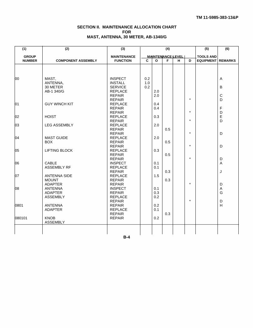
TM 11-5985-383-13&P
SECTION II. MAINTENANCE ALLOCATION CHARTFOR
MAST, ANTENNA, 30 METER, AB-1340/G
(1) (2) (3) (4) (5) (6)
GROUP MAINTENANCE MAINTENANCE LEVEL TOOLS ANDNUMBER COMPONENT ASSEMBLY FUNCTION C O F H D EQUIPMENT REMARKS
00 MAST, INSPECT 0.2 AANTENNA, INSTALL 1.030 METER SERVICE 0.2 BAB-1 340/G REPLACE 2.0
REPAIR 2.0 CREPAIR * D
01 GUY WINCH KIT REPLACE 0.4REPAIR 0.4 FREPAIR * D
02 HOIST REPLACE 0.3 EREPAIR * D
03 LEG ASSEMBLY REPLACE 2.0REPAIR 0.5REPAIR * D
04 MAST GUIDE REPLACE 2.0BOX REPAIR 0.5
REPAIR * D05 LIFTING BLOCK REPLACE 0.3
REPAIR 0.5REPAIR * D
06 CABLE INSPECT 0.1 AASSEMBLY RF REPLACE 0.1
REPAIR 0.3 J07 ANTENNA SIDE REPLACE 1.5
MOUNT REPAIR 0.3ADAPTER REPAIR * D
08 ANTENNA INSPECT 0.1 AADAPTER REPAIR 0.3 GASSEMBLY REPLACE 0.2
REPAIR * D0801 ANTENNA REPAIR 0.2 H
ADAPTER REPLACE 0.1REPAIR 0.3
080101 KNOB REPAIR 0.2ASSEMBLY
B-4

TM 11-5985-383-13&P
SECTION II. MAINTENANCE ALLOCATION CHARTFOR
MAST, ANTENNA, 30 METER, AB-1340/G
(1) (2) (3) (4) (5) (6)
GROUP MAINTENANCE MAINTENANCE LEVEL TOOLS ANDNUMBER COMPONENT ASSEMBLY FUNCTION C O F H D EQUIPMENT REMARKS
0802 CABLE INSPECT 0.1 AASSEMBLY REPLACE 0.1W5 REPAIR 0.3 E
9 GUY COLLAR REPLACE 0.1REPAIR 0.2REPAIR * D
10 PICKET REPLACE 0.1LOCATION REPAIR 0.2LINE REPAIR * D
11 BUBBLE REPLACE 0.1LEVEL REPAIR 0.5
REPAIR * D12 ROTATOR REPLACE 0.2
EXTENSION REPAIR 0.2REPAIR * D
13 MAST REPLACE 0.2SECTION REPAIR 0.2CARRIER REPAIR * D
14 HOIST REPLACE 0.1SUPPORT REPAIR 0.2BAR REPAIR * D
15 STEP INSPECT 0.1ASSEMBLY REPLACE 0.2
REPAIR 0.2REPAIR * D
16 MAST REPLACE 0.2SECTION REPAIR 0.2
REPAIR * D17 ANTENNA REPLACE 2.0 * D
ROTATOR REPAIR
B-5

TM 11-5985-383-13&P
SECTION III. TOOLS AND TEST EQUIPMENTFOR
MAST, ANTENNA, 30 METER, AB-1340/G
TOOL OR TEST MAINTENANCE NATIONAL/NATO TOOLEQUIPMENT CATEGORY NOMENCLATURE STOCK NUMBER NUMBERREF CODE
THE TOOLS FOR THE REPLACE/REPAIR PROCEDURES FOR THE MAST, ANTENNA, 30 METER(AB-1 340/G) ARE IDENTIFIED IN THE BASIC ISSUE ITEMS LIST OF THE LINE-OF-SIGHT MULTI-CHANNELRADIO TERMINAL.
B-6

TM 11-5985-383-13&P
SECTION IV. REMARKSFOR
MAST, ANTENNA, 30 METER, AB-1340/G
REFERENCE CODE REMARKS
A VISUALB PERFORM PMCS (LUBRICATION AND OIL)C REPAIR INCLUDES REPLACEMENT OF FOOT ADJUSTMENT BRACE, GUY
EXTENSION, SPIKE, FEEDER CABLESTRAP, ROTATOR EXTENSION ADAPTER,WINCH BAG, HOIST BAG, EQUIPMENT BAG, ACCESSORY BAG, PICKET BAG,PICKET AND CLAMP
D (*) REFER TO AUTOMATIC RETURN ITEMS LIST (ARIL) FOR SOURCE OF REPAIR.E REPAIR BY REPLACING HOIST HANDLE.F REPAIR BY REPLACING SNAP HOOK, PIN OR WINCH HANDLE.G REPAIR IS LIMITED TO REPLACEMENT OF EQUIPMENT STORAGE BAG, LOCATING
LINE, GUY ASSEMBLIES, GUY WIRE STAKES, TRIPOD STAKE, AND/ORCONNECTOR ADAPTER.
H REPAIR IS LIMITED TO REPLACEMENT OF KNOB, NYLON WASHER, AND/ORCOTTER PIN.
J REPAIR BY REPLACEMENT OF CONNECTORS AND/OR CAPS.
B-7/(B-8 blank)
TM 11-5985-383-13&PAPPENDIX C
COMPONENTS OF END ITEM LISTSection I. INTRODUCTION
C-1 SCOPE.This appendix lists integral components of and basic issue items for the Mast, Antenna, 30-Meter AB-1 340/G to help youinventory items required for safe and efficient operation.C-2 GENERAL.
This Components of End Item List is divided into the following sections:a. Section II. Integral Components of the Find Item. These items, when assembled, comprise the 30-meter mast
and must accompany it whenever it is transferred or turned in. The illustrations will help you identify these items.
b. Section III. Basic Issue Items. These are the minimum essential items required to place the 30-Meter Mast inoperation, to operate it, and to perform emergency repairs. They must accompany the 30-Meter Mast during operationand whenever it is transferred between accountable officers. The illustrations will assist you with hard-to-identify items.This manual is your authority to requisition replacement Bll, based on TOE/MTOE authorization of the end item.
C-3 EXPLANATION OF COLUMNS.
a. Illustration. This column is divided as follows:(1) Figure Number. Indicates the figure number of the illustration on which the item is shown.
(2) Item Number. The number used to identify item called out in the illustration.
b. National Stock Number. Indicates the National stock number assigned to the item and which will be used forrequisitioning.
c. Description. Indicates the Federal item name and, if required, a minimum description to identify the item. The partnumber indicates the primary number used by the manufacturer, which controls the design and characteristics of the itemby means of its engineering drawings, specifications, standards, and inspection requirements to identify an item or rangeof items. Following the part number, the Commercial and Government Entity (CAGE) code is shown in parentheses.
d. Location. The physical location of each item listed is given in this column. The lists are designed to inventory allitems in one area of the major item before moving on to an adjacent area.
e. Usable on Code. Not applicable.
f. Quantity Required (QYy Req’d). This column lists the quantity of each item required for a complete major item.
g. Quantity. This column is left blank for use during an inventory. Under the RCVD column, list the quantity youactually receive on your major item. The DATE columns are for your use when you inventory the major item.
C-1

TM 11-5985-383-13&P
SECTION II. INTEGRAL COMPONENTS OF END ITEM
(1) (2) (3) (4) (5) (6) (7)ILLUSTRATION NATIONAL DESCRIPTION LOCATION USUABLE QTY QUANTITY
(A) (B) STOCK ON REQDFIG. ITEM NUMBER PART NUMBER CAGE CODE RCVD DATE
5985-01-249-2581 30M MAST ASS’Y, AB-1340/G01-2731497-2 (67032)
CONSISTING OF:8105-01-370-4085 EQUIPMENT STORAGE BAG (FOR 1
ANT. CABLES)86-2734992-2 (67032)
5995-01-287-6473 CABLE, ANTENNA, (45 FT) 209-2733594-4 (67032)
1-1 5985-01-249-2581 30M MAST AND ACCESSORIES01-2731310-3 (67032)CONSISTING OF:
2-1 B 5985-01-360-2588 30M LEG ASSEMBLY 313981 (K3456)
2-1 Q 5985-01-323-6460 30M MAST SECTION CARRIERS 36067 (K3456)EACH CONTAINING:
2-1 H 5985-01-257-3144 MAST SECTIONS 813695 (K3456)
2-1 U 5985-01-360-9049 30M WINCH ASS’Y BAG (NO.2) 113986 (K3456)EACH CONTAINING:
2-1 J GUY WINCH KIT, 113985 (K3456)
5985-01-299-8175 - INCLUDES HANDLE 15472 (K3456)
2-1 L 4030-01-293-6237 SPIKE, 36409 (K3456)
2-1 V 5985-01-297-0725 30M HOIST ASS’Y BAG (NO.) 16327 (K3456)
C-2

TM 11-5985-383-13&P
SECTION II. INTEGRAL COMPONENTS OF END ITEM
(1) (2) (3) (4) (5) (6) (7)ILLUSTRATION NATIONAL DESCRIPTION LOCATION USUABLE QTY QUANTITY
(A) (B) STOCK ON REQDFIG. ITEM NUMBER PART NUMBER CAGE CODE RCVD DATE
CONTAINING:2-1 D 5985-01-257-3138 HOIST 1
6314 (K3456)5985-01-299-8175 - INCLUDES HANDLE 1
5472 (K3456)2-1 W 5985-01-360-9050 30M EQUIPMENT BAG (NO.4) 1
13987 (K3456)CONTAINING:
2-1 D 5985-01-360-9005 MAST GUIDE BOX 113984 (K3456)
2-1 E 5985-01-257-3140 LILFTING BLOCK 15246 (K3456)
2-1 F 5210-01-258-5942 BUBBLE LEVEL 15426 (K3456)
2-1 1 5975-01-297-6677 GUYCOIAR 45237 (K3456)
2-1 O 5985-01-293-6238 FEEDERCABLE STRAP 65809 (K3456)
2-1 X 5985-01-360-9051 30M ACCESSORY BAG (NO.5) 113988 (K3456)CONTAINING:
2-1 C 5985-01-257-9917 STEPASSENMBL 413694 (K3456)
5975-01-363-9255 FOOT ASSEMBLY 313989 (K3456)
2-1 G 5340-99-780-2415 FOOT ADJUSTMENT BRACE 15373 (K3456)
2-1 L 4030-01-293-6237 SPKE, 36409 (K3456)
2-1 U 5340-01-360-2243 CLAMP 313982 (K3456)
C-3
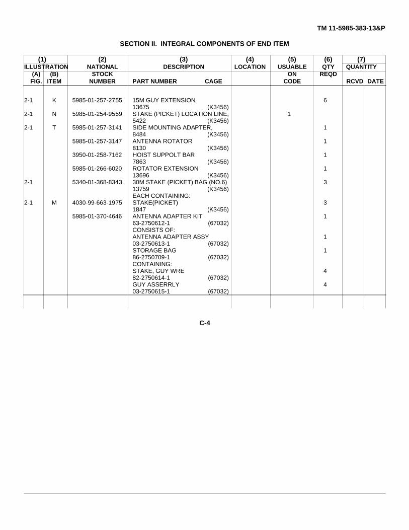
TM 11-5985-383-13&P
SECTION II. INTEGRAL COMPONENTS OF END ITEM
(1) (2) (3) (4) (5) (6) (7)ILLUSTRATION NATIONAL DESCRIPTION LOCATION USUABLE QTY QUANTITY
(A) (B) STOCK ON REQDFIG. ITEM NUMBER PART NUMBER CAGE CODE RCVD DATE
2-1 K 5985-01-257-2755 15M GUY EXTENSION, 613675 (K3456)
2-1 N 5985-01-254-9559 STAKE (PICKET) LOCATION LINE, 15422 (K3456)
2-1 T 5985-01-257-3141 SIDE MOUNTING ADAPTER, 18484 (K3456)
5985-01-257-3147 ANTENNA ROTATOR 18130 (K3456)
3950-01-258-7162 HOIST SUPPOLT BAR 17863 (K3456)
5985-01-266-6020 ROTATOR EXTENSION 113696 (K3456)
2-1 5340-01-368-8343 30M STAKE (PICKET) BAG (NO.6) 313759 (K3456)EACH CONTAINING:
2-1 M 4030-99-663-1975 STAKE(PICKET) 31847 (K3456)
5985-01-370-4646 ANTENNA ADAPTER KIT 163-2750612-1 (67032)CONSISTS OF:ANTENNA ADAPTER ASSY 103-2750613-1 (67032)STORAGE BAG 186-2750709-1 (67032)CONTAINING:STAKE, GUY WRE 482-2750614-1 (67032)GUY ASSERRLY 403-2750615-1 (67032)
C-4

TM 11-5985-383-13&P
SECTION II. INTEGRAL COMPONENTS OF END ITEM
(1) (2) (3) (4) (5) (6) (7)ILLUSTRATION NATIONAL DESCRIPTION LOCATION USUABLE QTY QUANTITY
(A) (B) STOCK ON REQDFIG. ITEM NUMBER PART NUMBER CAGE CODE RCVD DATE
LINE, LOCATING 189-2750616-1 (67032)
5935-01-035-5650 ADAPTER, CONNECTOR 1M55339/07-00029 (81349)
5995-01-358-6770 CABLE ASSY, SIGNAL, ELEC 109-2734023-2 (67032)STAKE, TRIPOD 182-2735123-1 (67032)
C-5/(C-6 blank)

TM 11-5985-383-13&P
APPENDIX EEXPENDABLE SUPPLIES AND MATERIALS LIST
Section I. INTRODUCTIONE-1 SCOPE.This appendix lists expendable supplies and materials you will need to operate and maintain the Mast, Antenna, 30 MeterAB-1340/G. These items are authorized to you by CTA 50-970, Expendable Items (Except Medical, Class V, Repair Parts,and Heraldic Items).E-2 EXPLANATION OF COLUMNS.
a. Column 1 - Item Number. This number is assigned to the entry in the listing and is referenced in thenarrative instructions to identify the material (e.g., "Use cleaning compound, item 3, App. E").
b. Column P - level. This column identifies the lowest level of maintenance that requires the listed item.C - Operator/CrewO - Organizational MaintenanceF - Direct Support MaintenanceH - General Support Maintenance.
c. Column 3 - National Stock Number. This is the National stock number assigned to the item; use it torequest or requisition the item.
d. Column 4- Description. Indicates the Federal item name and, if required, a description to identify the item.The last line for each item indicates the part number followed by the Commercial and Government Entity(CAGE) code in parentheses, if applicable.
e. Column 5 - Unit of Measure (U/M). Indicates the measure used in performing the actual maintenancefunction. This measure is expressed by a two-character alphabetical abbreviation (e.g., ea, in, pr). If theunit of measure differs from the unit of issue, requisition the lowest unit of issue that will satisfy yourrequirements.
E-1

TM 11-5985-383-13&P
SECTION II. EXPENDABLE SUPPLIES AND MATERIALS LIST
(1) (2) (3) (4) (5)
NATIONAL DESCRIPTIONITEM STOCK
NUMBER LEVEL NUMBER PART NO. AND FSCM UM/UI
1 O 7920-00-205-1711 Rags, Wiping 50 LBA-A-531 (58536) BAIL
2 O 9150-00-189-6727 Lubricating Oil QTMIL-L-2104 (81349)
3 O 6850-00-105-3084 Cleaning Compound, 16 OZTrichloriflouroethane
4 O 8030-00-081-2325 Sealing Compound, 50 CCMIL-S-22473, Grade H (05972)
5 O 8030-00-082-2508 Primer, 4 0ZMIL-S-22473, Grade T, Form R (05972)
E-2

TM 11-5985-383-13&P
APPENDIX FOPERATOR’S, UNIT, AND DIRECT SUPPORT MAINTENANCE
REPAIR PARTS AND SPECIAL TOOLS LISTSection I. INTRODUCTION
F-1. Scope.This appendix lists and authorizes spares and repair parts; special tools; special test, measurement, and diagnosticequipment (TMDE); and other special support equipment required for performance of unit and direct support maintenanceof the AB-1340/G. It authorizes the requisitioning, issue, and disposition of spares, repair parts and special tools asindicated by the source, maintenance and recoverability (SMR) codes.
F-2. General.
This Repair Parts and Special Tools List (RPSTL) is divided into the following sections:
a. Section II. Repair Parts List. A list of spares and repair parts authorized by this RPSTL for use in the performance ofmaintenance. The list also includes parts which must be removed for replacement of the authorized parts. Parts lists arecomposed of functional groups in ascending numeric sequence, with the parts in each group listed in ascending itemnumber sequence. Figure numbers are listed directly beneath the group header.
b. Section III. Special Tools List. Not applicable.
c. Section IV. Cross-Reference Indexes. A list, in National item identification number (NIIN) sequence, of all Nationalstock numbered items appearing in the listing, followed by a list in alphanumeric sequence of all part numbers appearing inthe listings. National stock numbers and part numbers are cross-referenced to each illustration figure and item numberappearance. The figure number and item number index lists figure and item numbers in numeric sequence and cross-references National stock number, Commercial and Government Entity Code (CAGEC) and part numbers.F-3. Explanation of Columns (Sections II and III).
a. item No. (Column (1)). Indicates the number used to identify items called out in the illustration.
b. SMR Code (Column (2)). The source, maintenance, and recoverability (SMR) code is a five-position code containingsupply/requisitioning information, maintenance category authorization criteria, and disposition instructions, as shown in thefollowing breakout:
F-1

TM 11-5985-383-13&P
NOTEComplete repair: Maintenance capacity, capability, and authority to perform allcorrective maintenance tasks of the "Repair" function in a use/user environment inorder to restore serviceability to a failed item.
(1) Source code. The source code tells you how to get an item needed for maintenance, repair, or overhaul of an enditem/equipment. Explanations of source codes follows:
Code Explanation
Stocked items; use the applicable NSN to request/requisition items with these source codes. They are authorized to the category indicated by the code entered in the third position of the SMR code.
NOTEItems coded PC are subject to deterioration.
Items with these codes are not to be requested/requisitioned individually. They are part of a kit which is authorized to the maintenance category indicated in the third position of the SMR code. The complete kit must be requisitioned and applied.
Items with these codes are not to be requested/requisitioned individually. They must be made from bulk material which is identified by the part number in the description and usable on code (UOC) column and listed in the Bulk Material group of the repair parts the item is authorized to you by the third position code of the SMR code, but the source code indicates it is made at a higher category, order the item from the higher category of maintenance.
Items with these codes are not to be requested/requisitioned individually. The parts that make up the assembled item must be requisitioned or fabricated and assembled at the category of maintenance indicated by the source code. If the third position code of the SMR code authorizes you to replace the item, but the source code indicates the item is assembled at a higher category, order the item from the higher category of maintenance.
F-2

TM 11-5985-383-13&PCode Explanation
XA - Do not requisition an "XA" coded item. Order its next higher assembly.XB - If an "XB" item is not available from salvage, order it using CAGEC and part number given.XC - Installation drawing, diagram, instruction sheet, field service drawing that is identified by
manufacturers part number.XD - Item is not stocked. Order an "XD" coded item through normal supply channels using the CAGEC
and part number given, if no NSN is available.NOTE
Cannibalization or controlled exchange, when authorized, may be used as a sourceof supply for items with the above source codes, except for those source coded"XA" or those aircraft support items restricted by requirements of AR 750-1.
(2) Maintenance code. Maintenance codes tell you the category of maintenance authorized to USE and REPAIRsupport items. The maintenance codes are entered in the third and fourth positions of the SMR code as follows:
(a) The maintenance code entered in the third position tells you the lowest maintenance category authorized toremove, replace, and use an item. The maintenance code entered in the third position will indicate authorization to one ofthe following categories of maintenance.
Code Application/ExplanationC - Crew or operator maintenance done within organizational or aviation unit maintenance.O - Organizational or aviation unit category can remove, replace, and use the item.F - Direct support or aviation intermediate category can remove, replace, and use the item.H - General support category can remove, replace, and use the item.L - Specialized repair activity can remove, replace, and use the item.D - Depot category can remove, replace, and use the item.
(b) The maintenance code entered in the fourth position tells whether or not the item is to be repaired andidentifies the lowest maintenance category with the capability to do complete repair (i.e., perform all authorized repairfunctions). This position will contain one of the following maintenance codes.
NOTESome limited repair may be done on the item at a lower category of maintenance, ifauthorized by the Maintenance Allocation Chart (MAC) and SMR codes.
Code Application/ExplanationO - Organizational or aviation unit is the lowest category that can do complete repair of the item.F - Direct support or aviation intermediate is the lowest category that can do complete repair of the
item.H - General support is the lowest category that can do complete repair of the item.L - Specialized repair activity is the lowest category that can do complete repair of the item.D - Depot is the lowest category that can do complete repair of the itemZ - Nonreparable. No repair is authorized.B - No repair is authorized. (No parts or special tools are authorized for the maintenance of a "B"
coded item.) However, the item may be reconditioned by adjusting, lubricating, etc., at the usercategory.
F-3

TM 11-5985-383-13&P
(3) Recoverability code. Recoverability codes are assigned to items to indicate the disposition action on unserviceableitems. The recoverability code is entered in the fifth position of the SMR code as follows:
Recoverability Application/ExplanationCodes _
Z - Nonreparable item. When unserviceable, condemn and dispose of the item at the category ofmaintenance shown in the third position of SMR code.
O - Reparable item. When uneconomically reparable, condemn and dispose of the item atorganizational or aviation unit category.
F - Reparable item. When uneconomically reparable, condemn and dispose of the item at directsupport or aviation intermediate category.
H - Reparable item. When uneconomically reparable, condemn and dispose of the item at generalsupport category.
D - Reparable item. When beyond lower category repair capability, return to depot. Condemnationand disposal of item not authorized below depot category.
L - Reparable item. Condemnation and disposal not authorized below specialized repair activity(SRA).
A - Item requires special handling or condemnation procedures because of specific reasons (e.g.,precious metal content, high dollar value, critical material, or hazardous material). Refer toappropriate manuals/directives for specific instruction.
c. CAGEC (Column (3)). The Commercial and Government Entity Code (CAGEC) is a 5-digit numeric code which isused to identify the manufacturer, distributor, or Government agency, etc., that supplies the item.
d. Part Number (Column (4)). Indicates the primary number used by the manufacturer (individual, company, firm,corporation or Government activity), which controls the design and characteristics of the item by means of its engineeringdrawings, specifications, standards, and inspection requirements to identify an item or range of items.
NOTEWhen you use a NSN to requisition an item, the item you receive may have adifferent part number from the part ordered.
e. Description and Usable on Code (UOC) (Column (5)). This column includes the following information:(1) The Federal Item name and, when required, a minimum description to identify the item.(2) The statement "END OF FIGURE" appears just below the last item description in Column (5) for a given
figure in both sections II and III.f. Qty (Column (6)). Indicates the quantity of the item used in the breakout shown on the illustration figure, which is
prepared for a functional group, subfunctional group, or an assembly. A "V" appearing in this column in lieu of aquantity indicates that the quantity is variable and the quantity may vary from application to application.
F-4. Explanation of Columns (Section IV).a. National Stock Number (NSN) Index.
(1) Stock number column. This column lists the NSN by National item identification number (NIIN) sequence.The NIIN consists of the last nine digits of the NSN. When using this column to locate an item, ignore thefirst four digits of the NSN. When requisitioning items, use the complete NSN (13 digits).
(2) Fig. column. This column lists the number of the figure where the item is identified/located. Theillustrations are in numerical sequence in sections II and IIIl.
(3) Item column. The item number identifies the item associated with the figure listed in the adjacent Fig.column. This item is also identified by the NSN listed on the same line.
F-4

TM 11-5985-383-13&P
b. Part Number Index. Part numbers in this index are listed by part number in ascending alphanumeric sequence.(1) CAGEC column. This column lists the Commercial and Government Entity Code (CAGEC).
(2) Part number column. This column indicates the part number assigned to the item.
(3) Stock number column. This column lists the National stock number for the associated part number andmanufacturer identified in the part number and CAGEC columns to the left.
(4) Fig. column. This column lists the number of the figure where the item is identified/located in sections IIand IIIl.
(5) Item column. The item number is that number assigned to the item as it appears in the figure referenced inthe adjacent figure number column.
c. Figure and Item Number Index.(1) Fig. column. This column lists the number of the figure where the item is identified/located in sections II
and III.
(2) Item column. The item number is that number assigned to the item as it appears in the figure referenced inthe adjacent figure number column.
(3) Stock number column. This column lists the National stock number for the item.
(4) CAGEC column. The Commercial and Government Entity Code (CAGEC) is a 5-digit numeric code used toidentify the manufacturer, distributor, or Government agency, etc., that supplies the item.
(5) Part number column. Indicates the primary number used by the manufacturer (individual, firm, corporation,or Government activity), which controls the design and characteristics of the item by means of itsengineering drawings, specifications, standards, and inspection requirements to identify an item or range ofitems.
F-5. Special Information.National Stock Numbers. National stock numbers (NSNs) that are missing from P source coded items have been appliedfor and will be added to this TM by future change/revision when they are entered in the Army Master Data File (AMDF).Until the NSNs are established and published, submit exception requisitions to: Commander, US Army Communications-Electronics Command and Fort Monmouth, ATTN: AMSEL-LC-LM, Fort Monmouth, New Jersey 07703-5007 for the partrequired to support your equipment.F-6. How to Locate Repair Parts.
a. When National stock number or part number is not known.(1) First. Using the table of contents, determine the assembly group or subassembly group to which the item
belongs. This is necessary since figures are prepared for assembly groups and subassembly groups, andlistings are divided into the same groups.
(2) Second. Find the figure covering the assembly group or subassembly group to which the item belongs.
(3) Third. Identify the item on the figure and note the item number.
(4) Fourth. Refer to the Repair Parts List for the figure to find the part number for the item number noted on thefigure.
(5) Fifth. Refer to the Part Number Index to find NSN, if assigned.
F-5

TM 11-5985-383-13&P
b. When National stock number or part is known.(1) First. Using the index of National stock numbers and part numbers, find the pertinent National stock number or
part number. The NSN index is in National item identification number (NIIN) sequence (para 4a(1)). The part numbers inthe part number index are listed in ascending alphanumeric sequence (para 4b). Both indexes cross-reference you to theillustration figure and item number of the item you are looking for.
(2) Second. After finding the figure and item number, verify that the item is the one you are looking for, then locatethe item number in the repair parts list for the figure.
F-7. Abbreviations.
Not applicable.
F-6
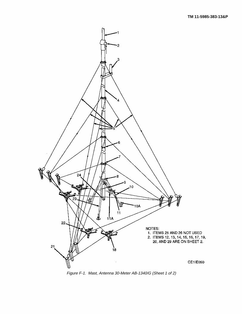
TM 11-5985-383-13&P
Figure F-1. Mast, Antenna 30-Meter AB-1340/G (Sheet 1 of 2)

TM 11-5985-383-13&P
Figure F-1. Mast, Antenna 30-Meter AB-1340/G (Sheet 2 of 2)

TM 11-5985-383-13&PSECTION II
(1) (2) (3) (4) (5) (6) (7)ITEM SMR PARTNO CODE NSN CAGEC NUMBER DESCRIPTION AND USABLE ON CODES (UOC) QTY
GROUP 00 MAST ANTENNA 30 METERAB-1340/G
FIGURE F-11 PAOZZ 5985012666020 K3456 13696 SUPPORT, ANTENNA.................................................... 12 PAODA 5985012573147 67032 8130 DRIVE, ANTENNA .......................................................... 13 PAODA 67032 8484 ANTENNA SIDE MOUNT................................................ 14 PAOZA 5985012573144 67032 13695 MAST .............................................................................. 245 PAOZZ 4030012642755 K3456 13675 GUY ATTACHMENT....................................................... 66 PAOZZ 5985012936238 K3456 5809 CABLE STRAP, FEEDER............................................... 67 PAOZZ 5975012976677 K3456 5237 COLLAR, CABLE ............................................................ 48 PAFFZ 5985013609005 67032 13984 MAST SECTION ............................................................. 19 PAOZZ 3950012587162 K3456 7863 BAR, HOIST SUPPORT.................................................. 410 PAOZZ 5985012579917 67032 13694 STEP ASSEMBLY........................................................... 410A PAOZZ 5975013629255 67032 13989 FOOT, ELECTRICAL EQU ............................................. 311 PAOZZ K3456 5472 HANDLE ANTENNA........................................................ 111A PAODA 5985012573138 67032 6314 HOIST ............................................................................. 112 PAOZZ 5210012585942 67032 5426 BUBBLE LEVEL.............................................................. 113 PAOZZ 5985012970725 14933 6327 CASE, ANTENNA ........................................................... 114 PAOZZ 5985013609049 67032 13986 CASE, ANTENNA ........................................................... 415 PAOZZ 5985013236460 67032 6067 MAST SECTION CARRIE............................................... 316 PAOZZ 5340997802415 K3456 5373 BRACE, CORNER .......................................................... 117 PAOZZ 5985012549559 67032 5422 STAKE, LOCATION LINE ............................................... 918 PAODA 5985013519084 67032 13985 ANTENNA ELEVATOR GR............................................. 419 PAOZZ 5985013609051 67032 13988 CASE, ANTENNA ........................................................... 120 PAOZZ 5985013609050 67032 13987 CASE, ANTENNA ........................................................... 121 PAOZZ 4030996631975 K3456 1847 STAKE, GUY................................................................... 922 PAOZZ 4030012936237 K3456 6409 SPIKE ............................................................................. 1523 PAFFA 5985013602588 67032 13981 TRIPOD, ANTENNA........................................................ 324 PAODA 5985012573140 67032 5246 LIFTING BLOCK ............................................................. 127 PAOZZ 5340013602243 67032 13982 CLAMP, LOOP................................................................ 128 PAOZZ 5340013688343 K3456 13759 PICKET BAG, STAKE..................................................... 129 PAOZZ 8105013704085 67032 86-2734992-2 BAG, TEXTILE................................................................ 130 PBODA 5985013704646 67032 63-2750612-1 ASSEMBLY, ADAPTER.................................................. 1
END OF FIGURE
F-1-1

TM 11-5985-383-13&P
Figure F-2. Guy Winch Kit

SECTION II TM 11-5985-383-13&P
(1) (2) (3) (4) (5) (6) (7)ITEM SMR PARTNO CODE NSN CAGEC NUMBER DESCRIPTION AND USABLE ON CODES (UOC) QTY
GROUP 01 GUY WINCH KITFIGURE F-2
1 PAOZZ 5985012998175 K3456 5472 HANDLE, ANTENNTA .................................................... 12 PAOZZ 5985012998176 K3456 5376 SUPPORT, ANTENNA.................................................... 33 PAOZZ 5340996369251 K3456 7547-B SNAP HOOK................................................................... 3
END OF FIGURE
F-2-1
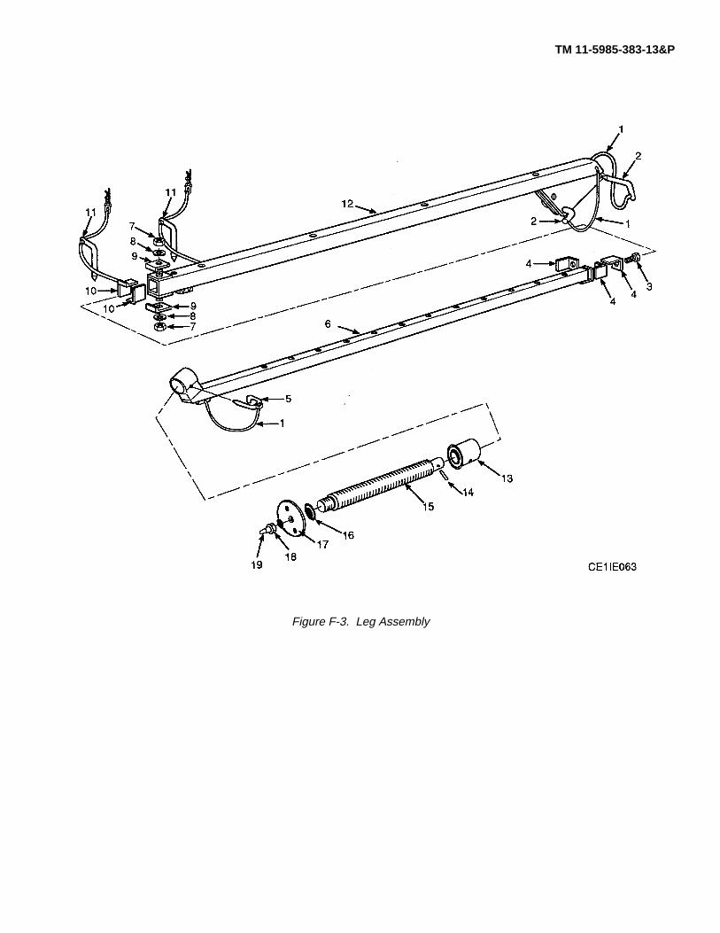
TM 11-5985-383-13&P
Figure F-3. Leg Assembly

SECTION II TM 11-5985-383-13&P
(1) (2) (3) (4) (5) (6) (7)ITEM SMR PARTNO CODE NSN CAGEC NUMBER DESCRIPTION AND USABLE ON CODES (UOC) QTY
GROUP 03 LEG ASSEMBLYFIGURE F-3
1 PAFZZ K3456 2529 CORD, FIBROUS ........................................................................................ 52 PAFZZ K3456 13703 PIN, DROP HEADD ........................................................................................ 23 PAFZZ K3456 B6267 SCREW HEX ........................................................................................ 14 PAFZZ K3456 13396 ANGLE, SLIDE ........................................................................................ 45 PAFZZ K3456 13701 ASSEMBLY FOOT CLIP................................................................................... 16 PAFZZ K3456 13431 INNER LEG ........................................................................................ 17 PAFZZ K3456 B5772 NUT, HEX ........................................................................................ 28 PAFZZ K3456 B5773 WASHER, FLAT ........................................................................................ 29 PAFZZ K3456 13399 PLATE, STOP ........................................................................................ 210 PAFZZ K3456 13397 PLATE, GIB CORNER...................................................................................... 211 PAFZZ K3456 13964 SUPPORT ANTENNA....................................................................................... 212 PAFZZ K3456 13402 OUTER LEG ........................................................................................ 113 PAFZZ K3456 13702 NUT FOOT ........................................................................................ 114 PAFZZ K3456 B8259 PIN, SPRING ........................................................................................ 115 PAFZZ K3456 13700 LEVELING SCREW ........................................................................................ 116 PAFZZ K3456 7986 WASHER ........................................................................................ 117 PAFZZ K3456 7989 FOOT PLATE ........................................................................................ 118 PAFZZ K3456 7985 WASHER FLAT ........................................................................................ 119 PAFZZ K3456 2046 STUD PLATE ........................................................................................ 1
END OF FIGURE
F-3-1

TM 11-5985-383-13&P
Figure F-4. Mast Guide Box

SECTION II TM 11-5985-383-13&P
(1) (2) (3) (4) (5) (6) (7)ITEM SMR PARTNO CODE NSN CAGEC NUMBER DESCRIPTION AND USABLE ON CODES (UOC) QTY
GROUP 04 MAST GUIDE BOXFIGURE 04
1 PAFZZ K3456 5267 GUIDE SLEEVE, MAST.................................................. 12 PAFZZ K3456 5431 PIN SUPPORT................................................................ 13 PAFZZ K3456 5432 BUSHING SHOULDER................................................... 14 PAFZZ K3456 5433 CAP PROTECTIVE......................................................... 15 PAFZZ K3456 13712 ROPE.............................................................................. 16 PAFZZ K3456 6758 SCREW, THUMB ............................................................ 27 PAFZZ K3456 7110 INSERT SCREW ............................................................ 28 PAFZZ K3456 18067 LABEL............................................................................. 19 PAFZZ K3456 B5998 SCREW DRIVE............................................................... 410 PAFZZ K3456 5266 GUIDE BOX MAST ......................................................... 111 PAFZZ K3456 B436 PIN .................................................................................. 212 PAFZZ K3456 13708 PIN .................................................................................. I113 PAFZZ K3456 B983 WASHER FLAT .............................................................. 114 PAFZZ K3456 B5770 CAPSCREW ................................................................... 215 PAFZZ K3456 5394 CLAP BLOCK.................................................................. 116 PAFZZ K3456 B2443 PIN, SPRING .................................................................. 117 PAFZZ K3456 5390 SCREW ASSY LOCKING ............................................... 118 PAFZZ K3456 13697 PIN ..................................................................................19 PAFZZ K3456 B3860 CORD.............................................................................. 120 PAFZZ K3456 5438 RING RETAINING........................................................... 121 PAFZZ K3456 B12177 NUT, WING..................................................................... 122 PAFZZ K3456 B12170 WASHER, FLAT ............................................................. 123 PAFZZ K3456 B12175 WASHER, LOCK ............................................................ 224 PAFZZ K3456 13962 STUD .............................................................................. 125 PAFZZ K3456 B12176 WASHER, LOCK ............................................................ 126 PAFZZ K3456 B12174 WASHER ........................................................................ 227 PAFZZ K3456 6316 STUD .............................................................................. 128 PAFZZ K3456 6317 FERRULE ....................................................................... 129 PAFZZ K3456 B5772 NUT, HEX ....................................................................... 130 PAFZZ K3456 13764 LABELL........................................................................... 131 PAFZZ K3456 13721 LABEL............................................................................. 135 PAFZZ K3456 7641/1 RING ASSY AZIMUTH.................................................... 133 PAFZZ K3456 B5905 NUT SELF LOCK............................................................ 234 PAFZZ K3456 B5773 WASHER, FLAT ............................................................. 235 PAFZZ K3456 B5904 BOLT HEX. .................................................................... 236 PAFZZ K3456 7643 HANDLE ASSY............................................................... 2
END OF FIGURE
F-4-1

TM 11-5985-383-13&P
Figure F-5. Lifting Block
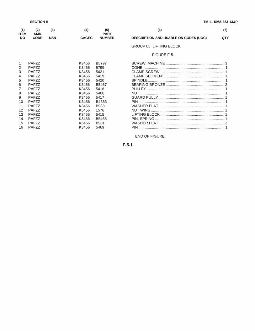
SECTION II TM 11-5985-383-13&P
(1) (2) (3) (4) (5) (6) (7)ITEM SMR PARTNO CODE NSN CAGEC NUMBER DESCRIPTION AND USABLE ON CODES (UOC) QTY
GROUP 05 LIFTING BLOCK
FIGURE F-5.
1 PAFZZ K3456 B5797 SCREW, MACHINE ........................................................ 32 PAFZZ K3456 5799 CONE.............................................................................. 13 PAFZZ K3456 5421 CLAMP SCREW ............................................................. 14 PAFZZ K3456 5419 CLAMP SEGMENT ......................................................... 15 PAFZZ K3456 5420 SPINDLE......................................................................... 16 PAFZZ K3456 B5467 BEARING BRONZE ........................................................ 27 PAFZZ K3456 5416 PULLEY .......................................................................... 18 PAFZZ K3456 5466 NUT................................................................................. 19 PAFZZ K3456 5417 GUARD PULLY............................................................... 110 PAFZZ K3456 B4383 PIN .................................................................................. 111 PAFZZ K3456 B983 WASHER FLAT .............................................................. 112 PAFZZ K3456 1576 NUT WING...................................................................... 113 PAFZZ K3456 5415 LIFTING BLOCK ............................................................. 114 PAFZZ K3456 B5468 PIN, SPRING .................................................................. 115 PAFZZ K3456 B981 WASHER FLAT .............................................................. 216 PAFZZ K3456 5469 PIN .................................................................................. 1
END OF FIGURE
F-5-1

TM 11-5985-383-13&P
Figure F-6. Cable Assembly, RF

SECTION II TM 11-5985-383-13&P
(1) (2) (3) (4) (5) (6) (7)ITEM SMR PARTNO CODE NSN CAGEC NUMBER DESCRIPTION AND USABLE ON CODES (UOC) QTY
GROUP 06 CABLE ASSEMBLY RF
FIGURE F-6.
1 PAOFF 5995012876473 67032 09-2733594-4 CABLE ASSEMBLY, SPEC ............................................ 12 PAFZZ 5935013326461 11556 1550-0454 CONNECTOR, PLUG, ELEC.......................................... 13 PAFZZ 5935013674313 11556 1540-0323 ADAPTER, CABLE CLAMP ............................................ 24 PAFZZ 5935013326462 11556 1550-0455 CONNECTOR, PLUG, ELEC.......................................... 1
END OF FIGURE
F-6-1

TM 11-5985-383-13&P
Figure F-7. Antenna Side Mount Adapter

SECTION II TM 11-5985-383-13&P
(1) (2) (3) (4) (5) (6) (7)ITEM SMR PARTNO CODE NSN CAGEC NUMBER DESCRIPTION AND USABLE ON CODES (UOC) QTY
GROUP 07 ANTENNA SIDE MOUNT ADAPTER
FIGURE F-7.
1 PAFZZ K3456 6386 PIN HINGE...................................................................... 12 PAFZZ K3456 B1742 PIN SPLIT COTTER........................................................ 13 PAFZZ K3456 B487 SOCKET GRABSCREW................................................. 14 PAFZZ K3456 6385 PIN RIVET TH................................................................. 15 PAFZZ K3456 7650 BRACKET ASSY COLUMN ............................................ 16 PAFZZ K3456 7045 STUD .............................................................................. 17 PAFZZ K3456 B1608 PIN SPLIT COTTER........................................................ 18 PAFZZ K3456 5878 WASHER FLAT .............................................................. 19 PAFZZ K3456 6380 HANDLE TEE.................................................................. 110 PAFZZ K3456 7639 BRACKET CLAMP.......................................................... 111 PAFZZ K3456 B984 WASHER FLAT .............................................................. 1
END OF FIGURE
F-7-1

TM 11-5985-383-13&P
Figure F-8. Antenna Adapter Assembly

SECTION II TM11-5985-383-13&P
(1) (2) (3) (4) (5) (6) (7)ITEM SMR PARTNO CODE NSN CAGEC NUMBER DESCRIPTION AND USABLE ON CODES (UOC) QTY
GROUP 08 ANTENNA ADAPTER ASSEMBLY
FIGURE F-8.
1 PAOFF 5985013719338 67032 03-2750613-1 ANTENNA SUPPORT GRO............................................ 12 PAOZZ 4030013711970 67032 82-2750614-1 STAKE, GUY................................................................... 43 PAOZZ 4010013717903 67032 03-2750615-1 GUY ................................................................................ 44 PAOZZ 5340013986548 67032 89-2750616-1 LINE, LOCATING............................................................ 15 PAOZZ 4030013711647 67032 82-2735123-1 ANCHOR, GUY............................................................... 16 PAOZZ 8105014002736 7D602 030168 BAG, SIGNAL EQUIPMEN ............................................. 17 PAOZZ 5935010355650 81349 M55339/07-00029 ADAPTER, CONNECTOR .............................................. 1
END OF FIGURE
F-8-1

TM 11-5985-383-13&P
Figure F-9. Antenna Adapter
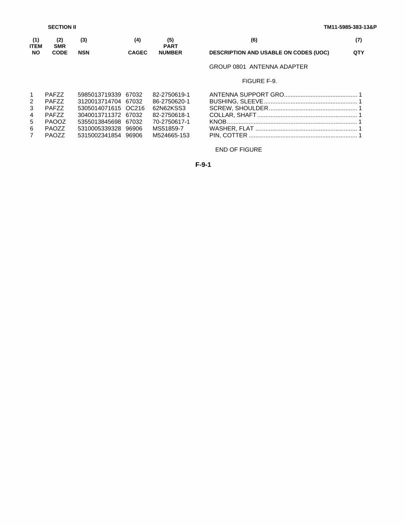
SECTION II TM11-5985-383-13&P
(1) (2) (3) (4) (5) (6) (7)ITEM SMR PARTNO CODE NSN CAGEC NUMBER DESCRIPTION AND USABLE ON CODES (UOC) QTY
GROUP 0801 ANTENNA ADAPTER
FIGURE F-9.
1 PAFZZ 5985013719339 67032 82-2750619-1 ANTENNA SUPPORT GRO............................................ 12 PAFZZ 3120013714704 67032 86-2750620-1 BUSHING, SLEEVE........................................................ 13 PAFZZ 5305014071615 OC216 62N62KSS3 SCREW, SHOULDER..................................................... 14 PAFZZ 3040013711372 67032 82-2750618-1 COLLAR, SHAFT ............................................................ 15 PAOOZ 5355013845698 67032 70-2750617-1 KNOB.............................................................................. 16 PAOZZ 5310005339328 96906 MS51859-7 WASHER, FLAT ............................................................. 17 PAOZZ 5315002341854 96906 M524665-153 PIN, COTTER ................................................................. 1
END OF FIGURE
F-9-1

TM 11-5985-383-13&P
Figure F-10. Knob Assembly

SECTION II TM11-5985-383-13&P
(1) (2) (3) (4) (5) (6) (7)ITEM SMR PARTNO CODE NSN CAGEC NUMBER DESCRIPTION AND USABLE ON CODES (UOC) QTY
GROUP 080101 KNOB ASSEMBLY
FIGURE 10.
1 PAOZZ 5355013716575 67032 82-1374648-11 KNOB.............................................................................. 12 PAOZZ 5315008414442 96906 MS16562-224 PIN, SPRING .................................................................. 13 PAOZZ 3040013846523 67032 70-2750617-101 SHAFT, STRAIGHT ........................................................ 1
END OF FIGURE
F-10-1

TM 11-5985-383-13&P
Figure F-11. Cable Assembly, W5

SECTION II TM11-5985-383-13&P
(1) (2) (3) (4) (5) (6) (7)ITEM SMR PARTNO CODE NSN CAGEC NUMBER DESCRIPTION AND USABLE ON CODES (UOC) QTY
GROUP 0802 CABLE ASSEMBLY, H5
FIGURE F-11.
1 PAOFF 5995013586770 67032 09-2734023-2 CABLE ASSEMBLY, SPEC ............................................ 12 PAFZA 5935012631779 91836 1205-14-9 CONNECTOR, PLUG, ELEC.......................................... 23 PAFZZ 5935010154400 91836 KN-89-12 COVER, ELECTRICAL CO............................................. 2
END OF FIGURE
F-11-1

TM 11-5985-383-13&P
Figure F-12. Guy Collar

SECTION II TM11-5985-383-13&P
(1) (2) (3) (4) (5) (6) (7)ITEM SMR PARTNO CODE NSN CAGEC NUMBER DESCRIPTION AND USABLE ON CODES (UOC) QTY
GROUP 09 GUY COLLAR
FIGURE F-12.
1 PAFZZ K3456 5387/1 PLATE, GUY COLLAR.................................................... 12 PAFZZ K3456 B3860 CORD.............................................................................. 23 PAFZZ K3456 5388 RETAINING HALF GUY.................................................. 24 PAFZZ K3456 5389 SCREW........................................................................... 2
END OF FIGURE
F-12-1
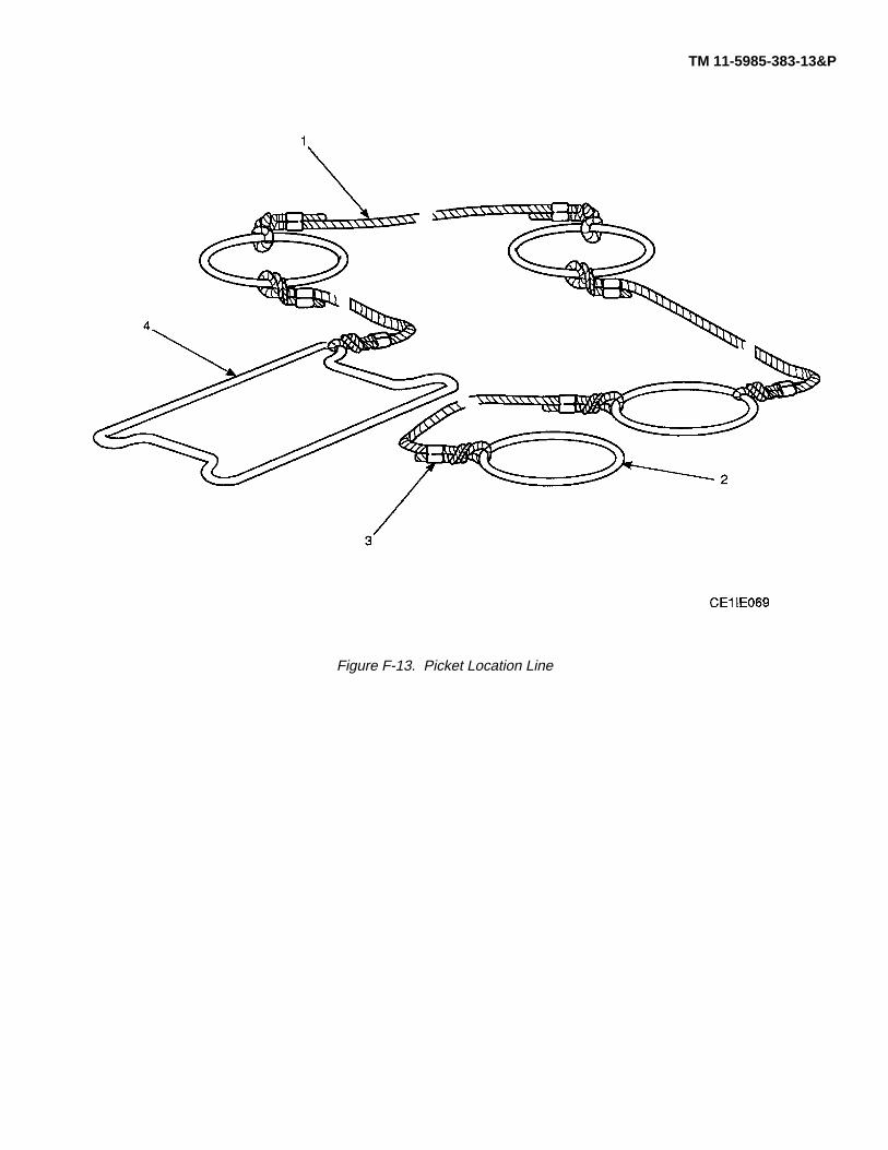
TM 11-5985-383-13&P
Figure F-13. Picket Location Line

SECTION II TM11-5985-383-13&P
(1) (2) (3) (4) (5) (6) (7)ITEM SMR PARTNO CODE NSN CAGEC NUMBER DESCRIPTION AND USABLE ON CODES (UOC) QTY
GROUP 10 PICKET LOCATION LINE
FIGURE F-13.
1 PAFZZ K3456 B3860 CORD.............................................................................. 12 PAFZZ K3456 5916 RING CONNECTING ...................................................... 43 PAFZZ K3456 B4327 SLEEVE HOSE............................................................... 84 PAFZZ K3456 6554 SPOOL............................................................................ 1
END OF FIGURE
F-13-1
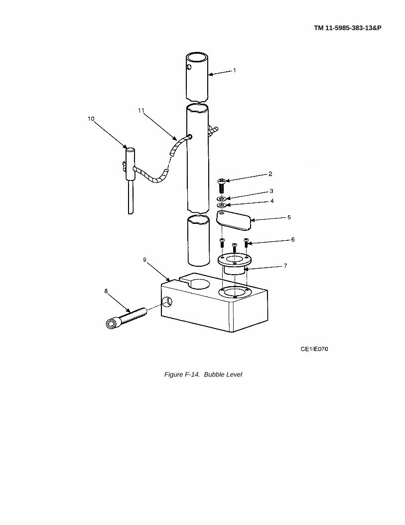
TM 11-5985-383-13&P
Figure F-14. Bubble Level

SECTION II TM11-5985-383-13&P
(1) (2) (3) (4) (5) (6) (7)ITEM SMR PARTNO CODE NSN CAGEC NUMBER DESCRIPTION AND USABLE ON CODES (UOC) QTY
GROUP 11 BUBBLE LEVEL
FIGURE F-14.
1 PAFZZ K3456 5429 EXTENSION ARM........................................................... 12 PAFZZ K3456 5357 SCREW PIVOT............................................................... 13 PAFZZ K3456 B635 HASHER, SPRING ......................................................... 14 PAFZZ K3456 B43 WASHER FLAT .............................................................. 15 PAFZZ K3456 5356 COVER, ACCESS........................................................... 16 PAFZZ K3456 B1440 SCREW........................................................................... 37 PAFZZ K3456 B5314 LEVEL BUBBLE.............................................................. 18 PAFZZ K3456 B5774 SOCKET ......................................................................... 19 PAFZZ K3456 5427 BLOCK LEVEL................................................................ 110 PAFZZ K3456 5428 LOCATING PIN............................................................... 111 PAFZZ K3456 B3860 CORD.............................................................................. 1
END OF FIGURE
F-14-1

TM 11-5985-383-13&P
Figure F-15. Rotator Extension

SECTION II TM11-5985-383-13&P
(1) (2) (3) (4) (5) (6) (7)ITEM SMR PARTNO CODE NSN CAGEC NUMBER DESCRIPTION AND USABLE ON CODES (UOC) QTY
GROUP 12 ROTATOR EXTENSION
FIGURE F-15.
1 PAFZZ 5985012666020 K3456 5817 SUPPORT, ANTENNA.................................................... 12 PAFZZ K3456 B4031 CORD, TENYLENE......................................................... 13 PAFZZ K3456 13703 PIN, DROP HEAD........................................................... 1
END OF FIGURE
F-15-1

TM 11-5985-383-13&P
Figure F-16. Mast Section Carrier

SECTION II TM11-5985-383-13&P
(1) (2) (3) (4) (5) (6) (7)ITEM SMR PARTNO CODE NSN CAGEC NUMBER DESCRIPTION AND USABLE ON CODES (UOC) QTY
GROUP 13 MAST SECTION CARRIER
FIGURE F-16.
1 PAFZZ K3456 6064 END SECTION MAST..................................................... 22 PAFZZ K3456 5759 STRAP ASSY MAST....................................................... 1
END OF FIGURE
F-16-1

TM 11-5985-383-13&P
Figure F-17. Hoist Support Bar
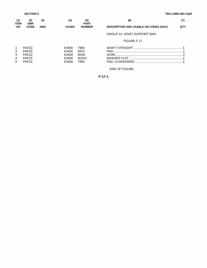
SECTION II TM11-5985-383-13&P
(1) (2) (3) (4) (5) (6) (7)ITEM SMR PARTNO CODE NSN CAGEC NUMBER DESCRIPTION AND USABLE ON CODES (UOC) QTY
GROUP 14 HOIST SUPPORT BAR
FIGURE F-17.
1 PAFZZ K3456 7984 SHAFT STRAIGHT ......................................................... 12 PAFZZ K3456 5970 PAD................................................................................. 13 PAFZZ K3456 B293 SCRE .............................................................................. 24 PAFZZ K3456 B2264 WASHER FLAT .............................................................. 25 PAFZZ K3456 7964 PAD, CUSHIONING........................................................ 2
END OF FIGURE
F-17-1

TM 11-5985-383-13&P
Figure F-18. Step Assembly

SECTION II TM11-5985-383-13&P
(1) (2) (3) (4) (5) (6) (7)ITEM SMR PARTNO CODE NSN CAGEC NUMBER DESCRIPTION AND USABLE ON CODES (UOC) QTY
GROUP 15 STEP ASSEMBLY
FIGURE F-18.
1 PAFZZ K3456 13430 STEP............................................................................... 12 PAFZZ K3456 13703 PIN, DROP HEAD........................................................... 13 PAFZZ K3456 B3860 CORD.............................................................................. 1
END OF FIGURE
F-18-1

TM 11-5985-383-13&P
Figure F-19. Mast Section

SECTION II TM 11-5985-383-13&P
(1) (2) (3) (4) (5) (6) (7)ITEM SMR PARTNO CODE NSN CAGEC NUMBER DESCRIPTION AND USABLE ON CODES (UOC) QTY
GROUP 16 MASTER SECTION
FIGURE F-19.
1 PAFZZ K3456 5294 TUBE ASSY.................................................................... 12 PAFZZ K3456 13705 PIN ROUND.................................................................... 13 PAFZZ K3456 B12126 PIN COTTER .................................................................. 2
END OF FIGURE
F-19-1

SECTION IV TM 11-5985-383-13&PCROSS- REFERENCE-INDEXES
NATIONAL STOCK NUMBER INDEXSTOCK NUMBER FIG. ITEM STOCK NUMBER FIG. ITEM
5315-00-234-1854 F-9 7 5355-01-384-5698 F-9 55310-00-533-9328 F-9 6 3040-01-384-6523 F-10 35315-00-841-4442 F-10 2 5340-01-398-6548 F-8 45935-01-015-4400 F-11 3 8105-01-400-2736 F-8 65935-01-035-5650 F-8 7 5305-01-407-1615 F-9 35985-01-254-9559 F-1 17 5340-99-636-9251 F-2 35985-01-257-3138 F-1 11A 4030-99-663-1975 F-1 215985-01-257-3140 F-1 24 5340-99-780-2415 F-1 165985-01-257-3141 F-3 35985-01-257-3144 F-I 45985-01-257-3147 F-1 25985-01-257-9917 F-1 105210-01-258-5942 F-1 123950-01-258-7162 F-1 95935-01-263-1779 F-11 24030-01-264-2755 F-1 55985-01-266-6020 F-1 1
F-15 15995-01-287-6473 F-6 14030-01-293-6237 F-1 225985-01-293-6238 F-1 65985-01-297-0725 F-1 135975-01-297-6677 F-1 75985-01-299-8175 F-1 11
F-2 15985-01-299-8176 F-2 25985-01-323-6460 F-1 155935-01-332-6461 F-6 25935-01-332-6462 F-6 45985-01-351-9084 F-1 185995-01-358-6770 F-11 15340-01-360-2243 F-1 275985-01-360-2588 F-1 235985-01-360-9005 F-1 85985-01-360-9049 F-1 145985-01-360-9050 F-1 205985-01-360-9051 F-1 195975-01-362-9255 F-1 10A5935-01-367-4313 F-6 35340-01-368-8343 F-1 288105-01-370-4085 F-1 295985-01-370-4646 F-1 303040-01-371-1372 F-9 44030-01-371-1647 F-8 54030-01-371-1970 F-8 23120-01-371-4704 F-9 25355-01-371-6575 F-10 14010-01-371-7903 F-8 35985-01-371-9338 F-8 15985-01-371-9339 F-9 1
F-I-1

SECTION IV TM 11-5985-383-13&PCROSS-REFERENCE INDEXES
PART NUMBER INDEX
CAGEC PART NUMBER STOCK NUMBER FIG. ITEM
K3456 B12126 F-19 3K3456 B12170 F-4 22K3456 B12174 F-4 26KJ456 B12175 F-4 23K3456 B12176 F-4 25K3456 B12177 F-4 21K3456 B1440 F-14 6K3456 B1608 F-7 7K3456 B1742 F-7 2K3456 B2264 F-17 4K3456 B2443 F-4 16K3456 B293 F-17 3K3456 B3860 F-4 19
F-12 2F-13 1F-14 11F-18 3
K3456 B4031 F-15 2K3456 B43 F-14 4K3456 B4327 F-13 3K3456 B4383 F-5 10K3456 B4836 F-4 11K3456 B487 F-7 3K3456 B5314 F-14 7K3456 B5467 F-5 6K3456 B5468 F-5 14K3456 B5770 F-4 14K3456 B5772 F-3 7
F-4 29K3456 B5773 F-3 8
F-4 34K3456 B5774 F-14 8K3456 B5797 F-5 1K3456 B5904 F-4 35K3456 B5905 F-4 33K3456 B5998 F-4 9K3456 B6267 F-3 3K3456 B635 F-14 3K5456 B8259 F-3 14K3456 B981 F-5 15K3456 B983 F-4 13
F-5 11K3456 B984 F-7 1191836 KN-89-12 5935-01-015-4400 F-11 396906 MS16562-224 5315-00-841-4442 F-10 296906 MS24665-153 5315-00-234-1854 F-9 796906 MS51859-7 5310-00-533-9328 F-9 681349 M55339/07-00029 5935-01-035-5650 F-8 767032 03-2750613-1 5985-01-371-9338 F-8 I67032 03-2750615-1 4010-01-371-7903 F-8 37D602 030168 8105-01-400-2736 F-8 6
F-I-2

SECTION IV TM 11-5985-383-13&PCROSS REFERENCE INDEXES
PART NUMBER INDEXCAGEC PART NUMBER STOCK NUMBER FIG. ITEM
67032 09-2733594-4 5995-01-287-6473 F-6 167032 09-2734023-2 5995-01-358-6770 F-11 191836 1205-14-9 5935-01-263-1779 F-11 2K3456 13396 F-3 4K3456 13397 F-3 10K3456 13399 F-3 9K3456 13402 F-3 12K3456 13430 F-18 1K3456 13431 F-3 6K3456 13675 4030-01-264-2755 F-1 567032 13694 5985-01-257-9917 F-1 1067032 13695 5985-01-257-3144 F-1 4K3456 13696 5985-01-266-6020 F-1 1K3456 13697 F-4 18K3456 13700 F-3 15K3456 13701 F-3 5K3456 13702 F-3 13K3456 13703 F-3 2
F-15 3F-18 2
K3456 13705 F-19 2K3456 13708 F-4 12K3456 13712 F-4 5K3456 13721 F-4 31K3456 13759 5340-01-368-8343 F-1 28K3456 13764 F-4 30K3456 13962 F-4 24K3456 13964 F-3 1167032 13981 5985-01-360-2588 F-1 2367032 13982 5340-01-360-2243 F-1 2767032 13984 5985-01-360-9005 F-1 867032 13985 5985-01-351-9084 F-1 1867032 13986 5985-01-360-9049 F-1 1467032 13987 5985-01-360-9050 F-1 2067032 13988 5985-01-360-9051 F-1 1967032 13989 5975-01-362-9255 F-1 10A11556 1540-0323 5935-01-367-4313 F-6 311556 1550-0454 5935-01-332-6461 F-6 211556 1550-0455 5935-01-332-6462 F-6 4K3456 1576 F-5 12K3456 18067 F-4 8K3456 1847 4030-99-663-1975 F-1 21K3456 2046 F-3 19K3456 2529 F-3 1K3456 5237 5975-01-297-6677 F-1 767032 5246 5985-01-257-3140 F-1 24K3456 5266 F-4 10K3456 5267 F-4 1K3456 5294 F-19 1K3456 5356 F-14 5K3456 5357 F-14 2
F-I-3

SECTION IV TM 11-5985-383-13&PCROSS REFERENCE INDEXES
PART NUMBER INDEXCAGEC PART NUMBER STOCK NUMBER FIG. ITEM
K3456 5373 5340-99-780-2415 F-1 16K3456 5376 5985-01-299-8176 F-2 2K3456 5387/1 F-12 1K3456 5388 F-12 3K3456 5389 F-12 4K3456 5390 F-4 17K3456 5394 F-4 15K3456 5415 F-5 13K3456 5416 F-5 7K3456 5417 F-5 9K3456 5419 F-5 4K3456 5420 F-5 5K3456 5421 F-5 367032 5422 5985-01-254-9559 F-1 1767032 54Z6 5210-01-258-5942 F-1 12K3456 5427 F-14 9K3456 5428 F-14 10K5456 5429 F-14 1K3456 5431 F-4 2K3456 5452 F-4 5K3456 5433 F-4 4K3456 5438 F-4 20K3456 5466 F-5 8K3456 5469 F-5 16K3456 5472 5985-01-299-8175 F-1 11
F-2 1K3456 5759 F-16 2K3456 5799 F-5 2K3456 5809 5985-01-293-6238 F-1 6K3456 5817 5985-01-266-6020 F-15 1K3456 5878 F-7 8K3456 5916 F-13 2K3456 5970 F-17 2K3456 6064 F-16 167032 6067 5985-01-323-6460 F-1 150C216 62N62KSS3 5305-01-407-1615 F-9 367032 63-2750612-1 5985-01-370-4646 F-1 3067032 6314 5985-01-257-31338 F-1 11AK3456 6316 F-4 27K3456 6317 F-4 2814933 6327 5985-01-297-0725 F-1 13K3456 6354 F-13 4K3456 6380 F-7 9K3456 6385 F-7 4K3456 6386 F-7 1K3456 6409 4030-01-293-6237 F-1 22K3456 6758 F-4 667032 70-2750617-1 5355-01-384-5698 F-9 567032 70-2750617-101 3040-01-384-6523 F-10 3K3456 7045 F-7 6K3456 7110 F-4 7
F-I-4
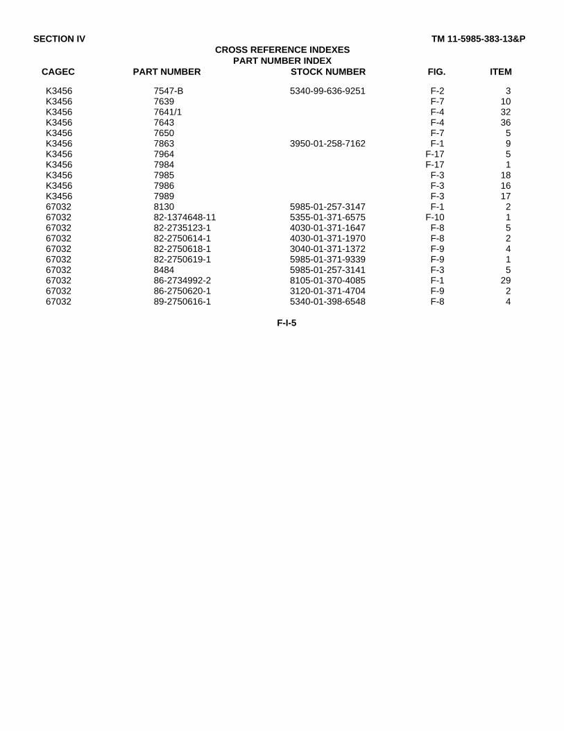
SECTION IV TM 11-5985-383-13&PCROSS REFERENCE INDEXES
PART NUMBER INDEXCAGEC PART NUMBER STOCK NUMBER FIG. ITEM
K3456 7547-B 5340-99-636-9251 F-2 3K3456 7639 F-7 10K3456 7641/1 F-4 32K3456 7643 F-4 36K3456 7650 F-7 5K3456 7863 3950-01-258-7162 F-1 9K3456 7964 F-17 5K3456 7984 F-17 1K3456 7985 F-3 18K3456 7986 F-3 16K3456 7989 F-3 1767032 8130 5985-01-257-3147 F-1 267032 82-1374648-11 5355-01-371-6575 F-10 167032 82-2735123-1 4030-01-371-1647 F-8 567032 82-2750614-1 4030-01-371-1970 F-8 267032 82-2750618-1 3040-01-371-1372 F-9 467032 82-2750619-1 5985-01-371-9339 F-9 167032 8484 5985-01-257-3141 F-3 567032 86-2734992-2 8105-01-370-4085 F-1 2967032 86-2750620-1 3120-01-371-4704 F-9 267032 89-2750616-1 5340-01-398-6548 F-8 4
F-I-5
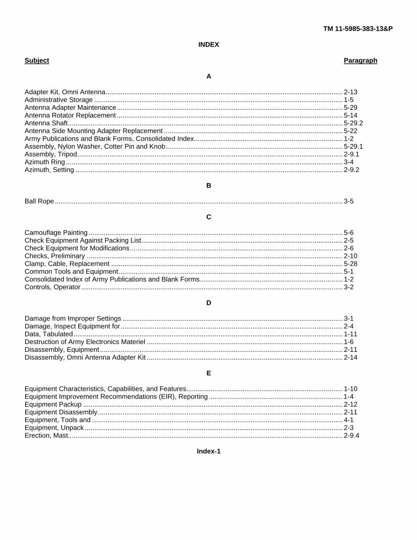
TM 11-5985-383-13&P
INDEX
Subject Paragraph
A
Adapter Kit, Omni Antenna.............................................................................................................................. 2-13Administrative Storage .................................................................................................................................... 1-5Antenna Adapter Maintenance........................................................................................................................ 5-29Antenna Rotator Replacement ........................................................................................................................ 5-14Antenna Shaft.................................................................................................................................................. 5-29.2Antenna Side Mounting Adapter Replacement ............................................................................................... 5-22Army Publications and Blank Forms, Consolidated Index............................................................................... 1-2Assembly, Nylon Washer, Cotter Pin and Knob.............................................................................................. 5-29.1Assembly, Tripod............................................................................................................................................. 2-9.1Azimuth Ring ................................................................................................................................................... 3-4Azimuth, Setting .............................................................................................................................................. 2-9.2
B
Ball Rope......................................................................................................................................................... 3-5
C
Camouflage Painting ....................................................................................................................................... 5-6Check Equipment Against Packing List........................................................................................................... 2-5Check Equipment for Modifications................................................................................................................. 2-6Checks, Preliminary ........................................................................................................................................ 2-10Clamp, Cable, Replacement ........................................................................................................................... 5-28Common Tools and Equipment....................................................................................................................... 5-1Consolidated Index of Army Publications and Blank Forms............................................................................ 1-2Controls, Operator........................................................................................................................................... 3-2
D
Damage from Improper Settings ..................................................................................................................... 3-1Damage, Inspect Equipment for...................................................................................................................... 2-4Data, Tabulated............................................................................................................................................... 1-11Destruction of Army Electronics Materiel ........................................................................................................ 1-6Disassembly, Equipment................................................................................................................................. 2-11Disassembly, Omni Antenna Adapter Kit ........................................................................................................ 2-14
E
Equipment Characteristics, Capabilities, and Features................................................................................... 1-10Equipment Improvement Recommendations (EIR), Reporting ....................................................................... 1-4Equipment Packup .......................................................................................................................................... 2-12Equipment Disassembly.................................................................................................................................. 2-11Equipment, Tools and ..................................................................................................................................... 4-1Equipment, Unpack ......................................................................................................................................... 2-3Erection, Mast.................................................................................................................................................. 2-9.4
Index-1

TM 11-5985-383-13&P
INDEX - Continued
Subject Paragraph
F
Feeder Cable Strap Replacement................................................................................................................... 5-16Finishes, Paints ............................................................................................................................................... 5-4Final Checks.................................................................................................................................................... 2-10
G
Guy Collar Replacement ................................................................................................................................. 5-21Guy Extension Replacement........................................................................................................................... 5-13Guy Winch Kit Replacement ........................................................................................................................... 5-12
H
Handles, Side .................................................................................................................................................. 3-3Hoist Replacement .......................................................................................................................................... 5-18Hoist Support Bar Replacement...................................................................................................................... 5-26
I
Improper Settings, Damage from .................................................................................................................... 3-1Information, Warranty...................................................................................................................................... 1-7Inspect Equipment for Damage....................................................................................................................... 2-4Installation, Guy Winch Kit .............................................................................................................................. 2-9.3Installation of 30-Meter Mast ........................................................................................................................... 2-9Installation, Omni Antenna Adapter Kit............................................................................................................ 2-13.1Installation, Omni Antenna Adapter Kit Guy Assembly ................................................................................... 2-13.2Instructions, Painting ....................................................................................................................................... 5-5
L
Leg Assembly Replacement............................................................................................................................ 5-20Lifting Block Replacement............................................................................................................................... 5-17List, Nomenclature Cross-Reference .............................................................................................................. 1-8
M
Maintenance, Antenna Adapter....................................................................................................................... 5-29Maintenance Forms, Records, and Reports ................................................................................................... 1-3Mast Erection................................................................................................................................................... 2-9.4Mast Guide Box Replacement......................................................................................................................... 5-19Mast Installation Team .................................................................................................................................... 2-8Mast Section Replacement ............................................................................................................................. 5-11Materiel, Destruction of Army Electronics ....................................................................................................... 1-6Modifications, Check Equipment for................................................................................................................ 2-6
Index-2

TM 11-5985-383-13&P
INDEX - Continued
Subject Paragraph
N
Nomenclature Cross-Reference List ............................................................................................................... 1-8Nylon Washer, Cotter Pin, and Knob Assembly.............................................................................................. 5-29.1
0
Operator Controls............................................................................................................................................ 3-2Omni Antenna Adapter Kit............................................................................................................................... 2-13Omni Antenna Adapter Kit Disassembly ......................................................................................................... 2-14
P
Packing List, Check Equipment Against.......................................................................................................... 2-5Packup, Equipment ......................................................................................................................................... 2-12Painting, Camouflage ...................................................................................................................................... 5-6Painting Instructions ........................................................................................................................................ 5-5Paints and Finishes ......................................................................................................................................... 5-4Parts, Repair.................................................................................................................................................... 4-2, 5-3Paths, Transmission........................................................................................................................................ 2-2PMCS Procedures........................................................................................................................................... 4-4, 5-8Procedures, PMCS.......................................................................................................................................... 4-4,5-8
R
Repair Parts..................................................................................................................................................... 4-2, 5-3Replacement
Antenna Rotator........................................................................................................................................ 5-14Antenna Side Mounting Adapter............................................................................................................... 5-22Cable Clamp ............................................................................................................................................. 5-28Feeder Cable Strap................................................................................................................................... 5-16Guy Collar ................................................................................................................................................. 5-21Guy Extension........................................................................................................................................... 5-13Guy Winch Kit ........................................................................................................................................... 5-12Hoist.......................................................................................................................................................... 5-18Hoist Support Bar...................................................................................................................................... 5-26Leg Assembly ........................................................................................................................................... 5-20Lifting Block............................................................................................................................................... 5-17Mast Guide Box ........................................................................................................................................ 5-19Mast Section ............................................................................................................................................. 5-11Rotator Extension Adapter........................................................................................................................ 5-15Snap Hook, Pulley Block........................................................................................................................... 5-27Spike ......................................................................................................................................................... 5-24Stake......................................................................................................................................................... 5-23Step Assembly .......................................................................................................................................... 5-25
Reporting Equipment Improvement Recommendations (EIR) ........................................................................ 1-4Ring, Azimuth .................................................................................................................................................. 3-4Rope, Ball ........................................................................................................................................................ 3-5Rotator Extension Adapter Replacement ........................................................................................................ 5-15
Index-3

TM 11-5985-383-13&P
INDEX- Continued
Subject Paragraph
S
Setting Azimuth ............................................................................................................................................... 2-9.2Shaft, Antenna................................................................................................................................................. 5-29.2Side Handles ................................................................................................................................................... 3-3Snap Hook, Pulley Block Replacement........................................................................................................... 5-27Special Tools, TMDE and Support Equipment................................................................................................ 5-2Spike Replacement ......................................................................................................................................... 5-24Stake Replacement ......................................................................................................................................... 5-23Step Assembly Replacement .......................................................................................................................... 5-25Storage, Administrative ................................................................................................................................... 1-5
T
Tabulated Data................................................................................................................................................ 1-11Team, Mast Installation ................................................................................................................................... 2-8Terrain Considerations .................................................................................................................................... 2-1Tools and Equipment, Common...................................................................................................................... 5-1Tools and Material Required ........................................................................................................................... 2-7Tools, Special, TMDE and Support Equipment............................................................................................... 5-2Transmission Paths......................................................................................................................................... 2-2Tripod Assembly.............................................................................................................................................. 2-9.2
U
Unpack Equipment .......................................................................................................................................... 2-3
W
Warranty Information....................................................................................................................................... 1-7
Index-4


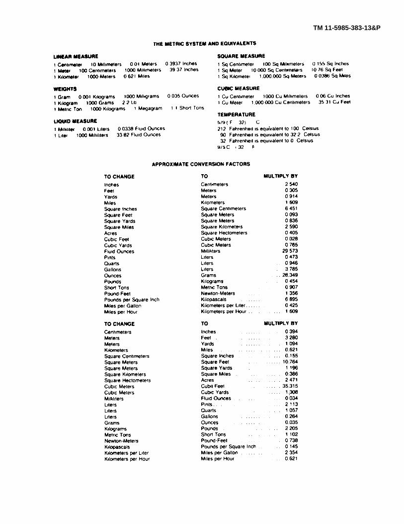
TM 11-5985-383-13&P

PIN: 075489-000‘