maharashtrastate board of technical …msbte.engg-info.website/sites/default/files/w 17 model...
TRANSCRIPT
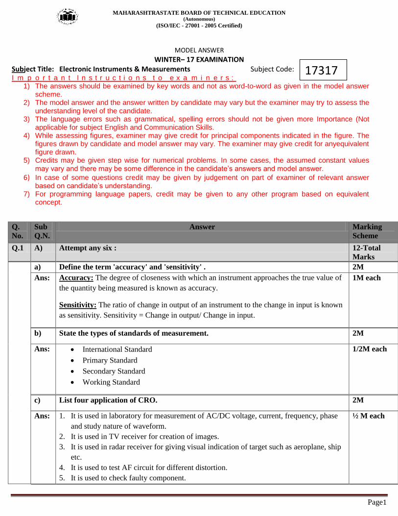
MAHARASHTRASTATE BOARD OF TECHNICAL EDUCATION (Autonomous)
(ISO/IEC - 27001 - 2005 Certified)
Page1
MODEL ANSWER
WINTER– 17 EXAMINATION Subject Title: Electronic Instruments & Measurements Subject Code: I m p o r t a n t I n s t r u c t i o n s t o e x a m i n e r s :
1) The answers should be examined by key words and not as word-to-word as given in the model answer scheme.
2) The model answer and the answer written by candidate may vary but the examiner may try to assess the understanding level of the candidate.
3) The language errors such as grammatical, spelling errors should not be given more Importance (Not applicable for subject English and Communication Skills.
4) While assessing figures, examiner may give credit for principal components indicated in the figure. The figures drawn by candidate and model answer may vary. The examiner may give credit for anyequivalent figure drawn.
5) Credits may be given step wise for numerical problems. In some cases, the assumed constant values may vary and there may be some difference in the candidate’s answers and model answer.
6) In case of some questions credit may be given by judgement on part of examiner of relevant answer based on candidate’s understanding.
7) For programming language papers, credit may be given to any other program based on equivalent concept.
Q.
No.
Sub
Q.N.
Answer Marking
Scheme
Q.1 A) Attempt any six : 12-Total
Marks
a) Define the term 'accuracy' and 'sensitivity' . 2M
Ans: Accuracy: The degree of closeness with which an instrument approaches the true value of
the quantity being measured is known as accuracy.
Sensitivity: The ratio of change in output of an instrument to the change in input is known
as sensitivity. Sensitivity = Change in output/ Change in input.
1M each
b) State the types of standards of measurement. 2M
Ans: International Standard
Primary Standard
Secondary Standard
Working Standard
1/2M each
c) List four application of CRO. 2M
Ans: 1. It is used in laboratory for measurement of AC/DC voltage, current, frequency, phase
and study nature of waveform.
2. It is used in TV receiver for creation of images.
3. It is used in radar receiver for giving visual indication of target such as aeroplane, ship
etc.
4. It is used to test AF circuit for different distortion.
5. It is used to check faulty component.
½ M each
17317

MAHARASHTRASTATE BOARD OF TECHNICAL EDUCATION (Autonomous)
(ISO/IEC - 27001 - 2005 Certified)
Page2
6. It is used to check signals at radio and TV receiver.
7. It is used to check B-H curve of different ferromagnetic material.
8. It is used in medical equipment such as ECG, patient monitor.
9. It is used to check modulation percentage of modulated wave.
10. It is also used to check radiation pattern generated by antenna.
d) List four dynamic characteristics. 2M
Ans: Characteristics-
Speed of response
Lag
Fidelity
Dynamic Error
½ M each
e) State two advantages of moving coil instrument. 2M
Ans: Advantages-
1. It has uniform scale.
2. Power consumption is low
3. It can be obtained in wide ranges.
4. High sensitivity & accuracy
5. It is unaffected by external magnetic field.
6. Additional damping device not required.
7. Hysteresis problem is not there.
1M each
f) What is the requirement of shunt in multirange ammeter? 2M
Ans: Requirement-
1. The temperature coefficients of the shunt and instruments should be low and nearly
identical
2. The resistance of shunt should not vary withj time.
3. It should carry the current without excessive temperature rise.
4. It should have a low thermal emf.
1M any two
g) What is the role of delay line in CRO ? 2M
Ans: The delay line is used in CRO to delay the signal for some time in the vertical sections. As
horizontal channel consists of trigger circuit and time based generator. this causes more
time to reach signal to horizontal plates than vertical plates. For synchronization of
reaching input signal at same time to both the plates in CRT.
2M
h) State the need of signal generators (any two). 2M
Ans: Need- 1. The generation of signals is an important activity of electronic development and
troubleshooting. Therefore a signal generator is a vital electronic instrument in
laboratory test setup which provides signals for general test purposes.
2. It is used to provide known test conditions for the performance evaluation of various
electronic systems and for replacing missing signals in systems being analyzed for
repair.
1M each

MAHARASHTRASTATE BOARD OF TECHNICAL EDUCATION (Autonomous)
(ISO/IEC - 27001 - 2005 Certified)
Page3
B) Attempt any two: 8-Total
Marks
8 M
a) Draw the circuit diagram of DC ammeter using basic 'D' Amsoval movement and
derive the expression for shunt resistance.
4M
Ans: Circuit diagram-
Explanation:
The basic movement of dc ammeter circuit consists of D‟ Arsonval galvanometer.
The coil winding of basic movement is small and light therefore it carries very
small current.
When large current is to be measured it is necessary to bypass a major part of the
current through a resistance called shunt.
For measurement of large current by using same movement a shunt resistor is
connected as shown in circuit.
The value of shunt resistor is very small so that most of the current pass through it
and only small current allow to pass through the coil.
The voltage across the shunt and movement must be same.
Vsh=Vm
IshRsh=ImRm
Rsh=ImRm/Ish
Rsh=ImRm/(I-Im)
2M
2M
b) Give significance of calibration. 4M
Ans: Calibration:
The process of deriving the value of a quantity by comparing that quantity with a standard
quantity is called as calibration. Calibration of instrument is done to obtain correct
unknown value of each scale reading on measuring instrument.
4M

MAHARASHTRASTATE BOARD OF TECHNICAL EDUCATION (Autonomous)
(ISO/IEC - 27001 - 2005 Certified)
Page4
Need of calibration:
1. To ensure reading from an instrument are consistent with other measurements.
2. To determine the accuracy of the instrument reading.
3. To establish the reliability of the instrument i.e. it can be trusted.
4. Calibration increases productivity, optimizes resources and assures consistency
c) List different types of errors and its source of generation/occurrence. 4M
Ans: 1. Static error : The error which occurs in stationary condition is called as static error. These are classified
as:
i. Gross errors: the errors which occur due to human mistakes while taking reading,
handling instrument incorrect setting or adjustment and improper use of instrument are
known as gross errors.
ii. Systematic errors: these errors occur due to shortcoming of the instrument such as
defective or worn part or aging or effect of environment on the instrument.
Instrumental error: the errors which arise due to inherent shortcoming of instrument,
misuse of instrument, loading effect of instrument are called as instrumental error.
Environmental error: these errors occur due to external condition to the measuring
instrument, such as temperature, pressure, humidity, dust and external magnetic field.
Observation error: these are introduced by the observer. the most common error is the
parallex error introduced in reading a meter scale.
iii. Random error: these errors are due to unknown causes, these error remain since the
systematic and gross error are removed,
2. Dynamic error: the difference between true value of a quantity changing with time and
value indicated by instrument if no static error is assumed is called as dynamic error.
1M- List
3M
explanation
Q .
2
Attempt any four : 16-Total
Marks
a) Describe the construction of PMMC instrument. 4M

MAHARASHTRASTATE BOARD OF TECHNICAL EDUCATION (Autonomous)
(ISO/IEC - 27001 - 2005 Certified)
Page5
Ans:
OR
Note-Any other relevant diagram shall be considered
1. The PMMC movement employ‟s a spring- loaded coil through which the measured
current flows.
2. The coil is in magnetic field of a permanent magnet and moves in a rotary fashion.
3. The amount of rotation is directly proportional to the amount of current flowing
through the coil.
4. A pointer attached to the coil indicates the position of the coil on a scale calibrated in
terms of current or voltage.
5. It responds to dc current only and has an almost linear calibration.
6. Magnetic shunt that varies the field strength is used for calibration.
2M
2M
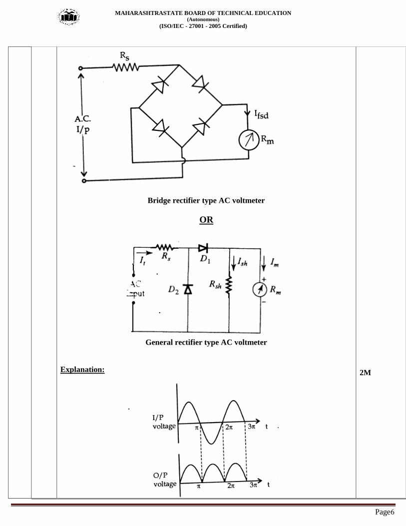
b) Explain the working of rectifier type of AC voltmeter with neat diagram ( any one). 4M
Ans: Diagram- 2M
MAHARASHTRASTATE BOARD OF TECHNICAL EDUCATION (Autonomous)
(ISO/IEC - 27001 - 2005 Certified)
Page6
Bridge rectifier type AC voltmeter
OR
General rectifier type AC voltmeter
Explanation:
2M

MAHARASHTRASTATE BOARD OF TECHNICAL EDUCATION (Autonomous)
(ISO/IEC - 27001 - 2005 Certified)
Page7
In full wave bridge rectifier the output voltage is double that of half wave rectifier . If we
assume diode has zero forward resistance and infinite reverse resistance then,
MAHARASHTRASTATE BOARD OF TECHNICAL EDUCATION (Autonomous)
(ISO/IEC - 27001 - 2005 Certified)
Page8
OR
Note-Any other relevant diagram shall be considered (half wave can be
considered)
c) State the reason for voltmeter never connected in series with source of emf. 4M
Ans: The voltmetre is used for measuring the electrical potential difference between two points
of a line ,where as the potential difference measured between two points of same wire/line
is zero. In short, the internal resistance of voltmetre is generally high, so you cannot
connect it in series.
4M
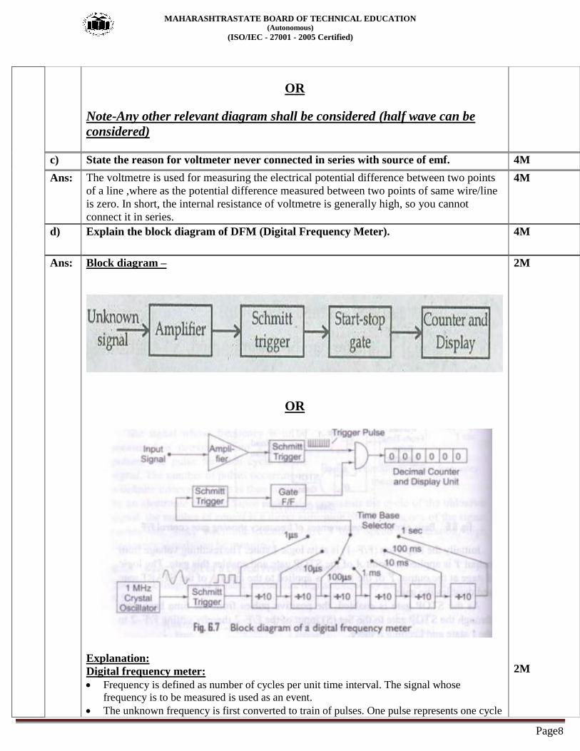
d) Explain the block diagram of DFM (Digital Frequency Meter). 4M
Ans: Block diagram –
OR
Explanation:
Digital frequency meter:
Frequency is defined as number of cycles per unit time interval. The signal whose
frequency is to be measured is used as an event.
The unknown frequency is first converted to train of pulses. One pulse represents one cycle
2M
2M

MAHARASHTRASTATE BOARD OF TECHNICAL EDUCATION (Autonomous)
(ISO/IEC - 27001 - 2005 Certified)
Page9
of unknown signal. These pulses are directly proportional to the frequency to be measured.
Amplifier:
The signal whose frequency is to be measured is first amplified. The output of
amplifier is applied to the Schmitt trigger.
Schmitt trigger:
The Schmitt trigger converts the signal into square wave having fast rise and fall times.
The square wave is then differentiated and clipped. Each pulse is proportional to each
cycle of unknown signal.
Start- Stop gate:
The output from Schmitt trigger is applied to start and stop gate. These pulses are
applied to the switch.
This switch is controlled by a signal having definite time interval. The main gate switch
is closed for known time interval.
When the gate is open, input pulses are allowed to pass through it. A counter will now
start to count these pulses.
When the gate is closed, input pulses are not allowed to pass through the gate. The
counter will now stop counting.
Counter and display:
The number of pulses during the period gate is open are counted by the counter.
If this interval between start and stop condition is known, the frequency of unknown
signal is measured.
F= N/t
Where,
F= Unknown frequency
N= Number of counts displayed by the counter.
t= Time interval between start and stop condition of the gate.
e) Compare DSO with CRO (any four points). 4M
Ans:
SR.NO CRO DSO
1 It is analog oscilloscope It is digital oscilloscope
2 Less accurate More accurate
3 No memory Memory present
4 Cost is less Cost is more
5 Cannot store signal Can store signal
1M each
any four
points
f) Explain the concept of time domain and frequency domain. 4M
Ans: Time Domain:
In general we observe electrical signals in amplitude versus time format where time is on
X- axis and amplitude is on Y- axis, this is known as time domain.
Example: CRO.
2M each

MAHARASHTRASTATE BOARD OF TECHNICAL EDUCATION (Autonomous)
(ISO/IEC - 27001 - 2005 Certified)
Page10
Fig: Waveform observed on CRO
Frequency Domain:
We know that during long distance communication signal get distorted. The main
advantage of time domain analysis is that we cannot differentiate the complex frequency
signals or distorted signal.
To overcome disadvantage of time domain, we observed the signal in amplitude versus
frequency format is known as frequency domain.
In frequency domain the complex frequency signal can be plotted as separate spectrum
for each frequency so it becomes easy to analyze the information present in the signal.
Example: Spectrum analyzer.
Fig: Waveform of Spectrum analyzer.
Q. 3 Attempt any four: 16-Total
Marks
a) What is loading effect and sensitivity of multirange voltmeter? 4M
Ans: Loading Effect: When selecting a meter for a certain voltage measurement, it is important
to consider the sensitivity of a dc voltmeter. A low sensitivity meter gives a correct reading
when measuring voltages in a low resistance circuit, but it is certain to produce unreliable
readings in a high resistance circuit. A voltmeter when connected across two points in a
highly resistive circuits, acts as a shunt for that portion of the circuit, reducing the total
equivalent resistance of that portion. The meter then indicates a lower reading than what
existed before the meter was connected. This is called the loading effect of an instrument.
Sensitivity: The sensitivity of voltmeter means the response given by a voltmeter to input
signal.
It is the ratio of total resistance (RT) to the voltage range S = RT / V
Where, RT – Total resistance…… RT = RS + Rm
V= Voltage range.
OR
Loading
effect (2M)
Sensitivity
(2M)
MAHARASHTRASTATE BOARD OF TECHNICAL EDUCATION (Autonomous)
(ISO/IEC - 27001 - 2005 Certified)
Page11
It is also defined as the reciprocal of full scale deflection current of the basic movement.
S = 1 / Ifsd
Ifsd = full scale deflection current.
b) How does electron beam generate horizontal refline on CRT screen? 4M
Ans: The Electron Gun Assembly produces a sharply focused beam of electron which is
accelerated to a high velocity.
The electrons are accelerated by high positive potential which is applied to the pre-
accelerating and accelerating anodes.
The electron beam is focused by the focusing anode.
This focused beam of electron strikes the fluorescent screen with sufficient energy to
cause a luminous spot on the screen.
After leaving the electron gun, the electron beam passes through two pairs of
„electrostatic deflection plates‟. The voltages applied to these plates deflect the beam.
Voltages applied to horizontal deflecting plates move the beam horizontally from one
side to another.
Due to the horizontal movement the beam is positioned horizontally on the screen and
a horizontal trace on CRO screen is obtained
½ M for
each point
c) Write the steps (and procedure) for measurement of frequency and phase of signal by
CRO.
4M
Ans: Phase :
The phase measurement can be done by using Lissajous figures.
The CRO is set to operate in the X- Y mode, then the display obtained on the screen of a
CRO is called Lissajous pattern, when two sine waves of the same frequency are applied to
the CRO.
( One vertical and one horizontal deflection plates).
Depending on the phase shift between the two signals, the shape of the Lissajous pattern
will go on changing.
The phase shift is given by,
Ө = sin-1 (A/B)
Frequency :
The period and frequency of periodic signals are easily measured.
The period is the time between two identical points of successive cycle of the waveform.
Period= no of divisions × position of time/div knob.
The frequency is inversely proportional to the period.
Frequency= 1/Period
Phase-2M
Frequency-
2M
d) How does Halfwave rectifier typeAC analog voltmeter use to measure unknown
voltage.
4M
Ans:

MAHARASHTRASTATE BOARD OF TECHNICAL EDUCATION (Autonomous)
(ISO/IEC - 27001 - 2005 Certified)
Page12
Diagram-
A circuit of a voltmeter using a half wave rectifier is shown Suppose that the meter resistance is and that of a multiplier is , neglect the
forward resistance of the diode. When a d.c voltage = V is applied to the circuit, the current through the meter is
which produces full scale deflection.
Now suppose an a.c sinusoidal voltage V = √ is applied to the
same circuit where = peak value of a.c voltage & V = rms value of a.c voltage. This voltage gets rectified and a unidirectional pulsating voltage is produced at the
output of the rectifier. This pulsating voltage produces a pulsating current and
hence a pulsating torque. Because of the inertia of the moving parts PMMC indicates a deflection
corresponding to average value of current which is dependent up on the average
value of applied voltage. Average value of voltage =
∫
=
√
Therefore, current through the meter is
which produces a deflection that is
0.45 times that produced with d.c of equal magnitude, V.
Hence sensitivity of a half wave rectifier instrument with a.c 0.45 times its
sensitivity with d.c.
= 0.45
Therefore the pointer will deflect for a full scale of 10V d.c is applied and 4.5V
when a 10 sinusoidal signal is applied. This means that an a.c voltmeter is not
as sensitive as a d.c voltmeter.
1M
2M

MAHARASHTRASTATE BOARD OF TECHNICAL EDUCATION (Autonomous)
(ISO/IEC - 27001 - 2005 Certified)
Page13
1M
e) Calculate the value of multiplier, i fbasic movement having (l fsd) full scale deflection
current of lOrnA and Internal resistance Rm of 50 n is used to measure 400 volts.
4M
Ans: Given data:
Ifsd=10mA
Rm=50Ω
V=400volts.
Rs=
=
Rs= 40000-50
Rs= 39950Ω
Rs= 39.95kΩ
1M
1M
1M
1M
f) Describe the block diagram of Ramp type of voltmeter. 4M
Ans: Block diagram-
2M

MAHARASHTRASTATE BOARD OF TECHNICAL EDUCATION (Autonomous)
(ISO/IEC - 27001 - 2005 Certified)
Page14
Working:
Unknown voltage to be measured is applied to the input side.
Initially the logic circuit sends the reset signal to the counter and digital readout.
Before the starting of measurement the counter and digital readout are resetted.
The ramp generator, generates the ramp wave. This ramp may be positive going or
negative going. Consider a positive going ramp. This ramp signal is applied to the both of
the comparators.
Here each comparator is design in such a way that when both the input signals of a
comparators are equal then the comparator changes its states. That means when both input
signals are equal then the output voltage swing of a comparator takes place.
In this system, one comparator is used to open the gate while other comparator is used to
close the gate.
In this case we have considered a positive going ramp pulse.
The reference voltage for the second comparator is the ground level.
When the ramp signal crosses the zero voltage then both inputs of seconds comparators
becoms equal.
So the output stage of this comparator changes. This signal is sent to the logic control.
The logic control circuit gives the signal to the logic gate. This causes the opening of
gate.
Once the gate is opened; the counter starts counting the number of pulses. These number
of pulses are provided by the local oscillator.
The number of pulses generated by the local oscillator in a particular time interval
depends on the frequency of local oscillator.
The ramp signal is applied to both comparators. One input terminal of first comparator is
connected to the input unknown voltage.
When the ramp voltage becomes equal to input unknown voltage; then both input signals
of first comparators are equal. So the output stage of this comparator are changes.
2M

MAHARASHTRASTATE BOARD OF TECHNICAL EDUCATION (Autonomous)
(ISO/IEC - 27001 - 2005 Certified)
Page15
Now the signal from logic control circuit is used to close the gate.
Once the gate is closed, the number of pulses will stop passing to counter. So the counter
will stop the counting operation.
During the time interval between opening and closing the gate; a definite number of
pulses will be counted by the counter.
This number is displayed by the digital readout.
Q. 4 A) Attempt any four : 16-Total
Marks
a) Compare analog instruments with digital instruments. 4M
Ans:
Sr. No. Parameter Analog instrument Digital instrument
1 Principle The instrument that
displays analog signals
is called as an analog
instrument
The instrument that
displays digital signals
is called as an digital
instrument
2 Accuracy Low High
3 Resolution Low High
4 Power required Require more power Require less power
5 Cost Cheap costly
6 Portability Portable Less
7 Observational error Considerable
Observational error
Free from
Observational error
8 examples PMMC instrument,
analog ammeter,
analog voltmeter.
DMM, DVM
each 1M
b) A 2mA meter with internal resistance of 100 n is to be converted to 0 - 150 rnA
ammeter.
Calculate the value of Shunt resistance required.
4M
Ans: Given data:
Im=2mA
Rm=100Ω
I=1-150mA
Rsh =
=
=
Rsh=1.35Ω
1M
1M
1M
1M
c) State two advantages and two disadvantages of PMMC meter. 4M
Ans: Advantages of PMMC meter: (Any two)
1. It has uniform scale.
2. Power consumption is low
2M

MAHARASHTRASTATE BOARD OF TECHNICAL EDUCATION (Autonomous)
(ISO/IEC - 27001 - 2005 Certified)
Page16
3. It can be obtained in wide ranges. 4. High sensitivity & accuracy
5. It is unaffected by external magnetic field.
6. Additional damping device not required.
Disadvantages of PMMC meter: (Any two)
1. It is suitable for d.c. measurement only.
2. Comparatively high cost than moving iron type instrument.
3. Ageing of permanent magnet & spring introduce errors
4. Friction due to jewel- pivot suspension.
2M
d) Calculate the vertical input frequency if horizontal frequency is 1500 Hz for fig. (a)
and fig. (b).
4M
Ans: Fig a .
X=2, Y= 2
Therefore, fy= X/Y x f
Fy = 2/2 x 1500
Fy= 1.5 KHZ
Fig b.
X=3, Y=2
Therefore, fy= X/Y x fx = 3/2 x1500Hz
Fy= 2.25 KHZ
1M
1M
1M
1M
e) Explain the block diagram of function generator. 4M
Ans: Block diagram:
Working:
The frequency is controlled by varying the capacitor in LC or RC circuit. In this
instrument the frequency is controlled by varying the magnitude of current which
2M
2M

MAHARASHTRASTATE BOARD OF TECHNICAL EDUCATION (Autonomous)
(ISO/IEC - 27001 - 2005 Certified)
Page17
drives the integrator. The instrument produces sine, triangular and square waves
with a frequency range of 0.01 Hz to 100 kHz.
The frequency controlled voltage regulates two current sources.
The upper current source supplies constant current to the integrator whose output
voltage increases linearly with time, according to the equation of the output signal
voltage.
t eout = -1 ∫ i dt C 0 An increase or decrease in the current increases or decreases
the slope of the output voltage and hence controls the frequency.
The voltage comparator multivibrator changes states at a pre- determined maximum
level of the integrator output voltage.
This change cuts off the upper current supply and switches on the lower current
supply.
The lower current source supplies a reverse current to the integrator, so that its
output decreases linearly with time.
When the output reaches a pre-determined minimum level, the voltage comparator
again changes state and switches on the upper current source.
The output of the integrator is a triangular waveform whose frequency is
determined by the magnitude of the current supplied by the constant current
sources.
The comparator output delivers a square wave voltage of the same frequency.
The resistance diode network alters the slope of the triangular wave as its amplitude
changes and produces a sine wave with less than 1% distortion.
f) Explain the working principle of wave analyser with neat block diagram. 4M
Ans: Block diagram:
working principle:
A wave analyzer consists of a primary detector, which is a simple LC circuit.
This LC circuit is adjusted for resonance at the frequency of the particular harmonic
component to be measured.
2M
2M

MAHARASHTRASTATE BOARD OF TECHNICAL EDUCATION (Autonomous)
(ISO/IEC - 27001 - 2005 Certified)
Page18
The intermediate stage is a full-wave rectifier to obtain the average value of input
signal.
The indicating device is a simple DC voltmeter that is calibrated to read the peak
value of the sinusoidal input voltage.
Since the LC circuit is tuned to a single frequency, it passes only the frequency to
which it is tuned and rejects all other frequencies.
A number of tuned filters, connected to the indicating device through a selector
switch would be required for a useful wave analyzer.
Q.5 Attempt any four : 16-Total
Marks
a) i) What is the resolution of 4 ½ DMM.
ii) Write two uses of Video pattern generator.
4M
Ans: i) Resolution of 4 ½ DMM: The number of digit positions used in a digital meter
determines the resolution. Hence a four and a half digit meter could display up to 19999.
Resolution can also be defined as the ratio of change in analog output voltage resulting
from a change of 1 LSB at the digital input.
ii) Uses of Video pattern generator: It is a device which can generate video signals that
can be fed to a TV or video monitor. The pattern consists of geometrical figures such as
circles, ellipses, horizontal/vertical lines and bars, checker board, dots etc.
The various patterns are used for (1)The horizontal pattern is used to check vertical linearity.
(2) The vertical pattern is used to check horizontal linearity
(3) The cross hatch pattern is used to check vertical and horizontal linearity
simultaneously and more precisely.
(4) FM signal is used for aligning sound IF as well as discriminator circuit.
2M
2M
b) Find the phase relation for following fig. (c) and fig. (d).
4M
Ans: Ѳ=Sin-1
A/B
where A= Y axis intersect B= maximum vertical deflection
1) A=5, B=7 Ѳ=Sin-1
A/B = 45.580
2) A=0, B=7 Ѳ=Sin-1
A/B = 00
2 M
2 M
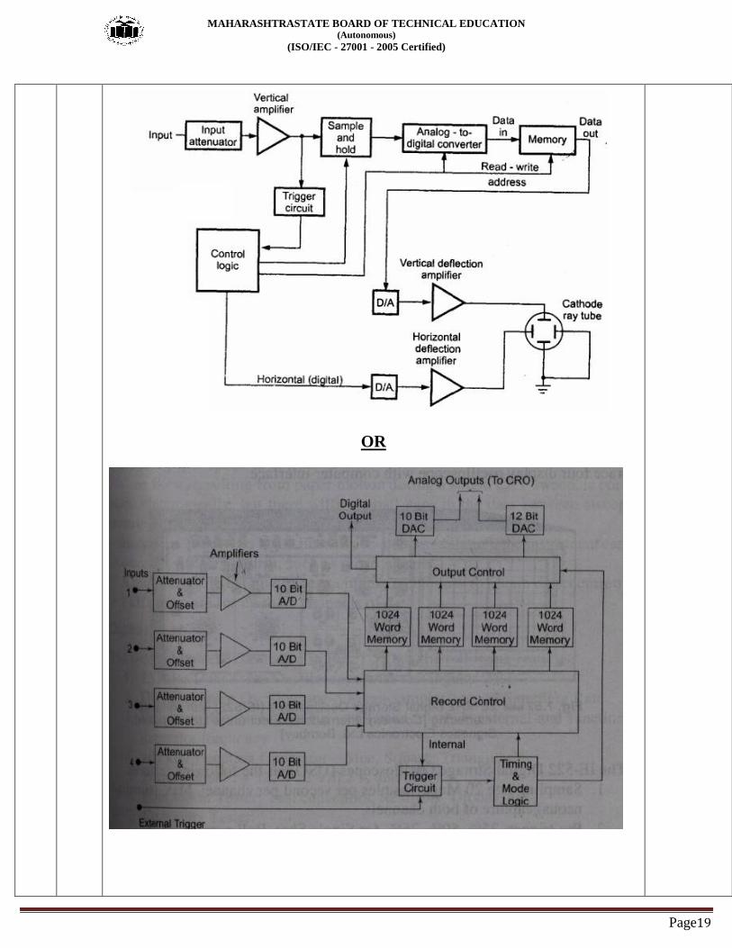
c) Draw the block diagram of DSO. 4M
Ans: Block diagram-
4M for
Labeled
diagram
MAHARASHTRASTATE BOARD OF TECHNICAL EDUCATION (Autonomous)
(ISO/IEC - 27001 - 2005 Certified)
Page19
OR

MAHARASHTRASTATE BOARD OF TECHNICAL EDUCATION (Autonomous)
(ISO/IEC - 27001 - 2005 Certified)
Page20
d) Draw and explain RF signal generator. 4M
Ans: Diagram-
-The RF signal generator produces controllable voltage and frequency. The output signal
from a signal generator is either frequency modulated or amplitude modulated. It is
commonly used in radio receivers and transmitters. It is basically an RF signal generator.
Operation: Figure shows the block diagram of RF signal generator. The RF oscillator is
formed by an LC tank circuit. It generates a stable carrier frequency over any frequency
range. The oscillator is an LC tank circuit, so the frequency stability is limited. The
frequency range is selected by connecting a switch to particular capacitor. The amplitude
modulation is provided by an internal sine wave generated. It may also provide by an
external source. The modulation is done in a wide band amplifier. For modulation sine,
square, triangular wave or pulse maybe used. The output of wideband amplifier is
connected to attenuator. The required range of attenuation is selected and level of output
signal can be controlled. The output meter is used to give an indication of output signal.
2M for
Diagram
(Any
relevant
diagram
can be
considered)
2M for
Explanatio
n
e) Explain the block diagram of spectrum analyser. 4M
Ans: Diagram-
Explanation-
The main function of spectrum analyzer is to be obtaining the amplitude vs frequency plot
from the frequency spectrum under test. They can be classified as scanning type & non-
scanning type.The sawtooth generator generates the sawtooth waveform. This sawtooth
waveform is applied to horizontal plates of CRO. The sawtooth signal also applied to
voltage tuned local oscillator. This act as frequency controlled element of local oscillator.
When sawtooth signal is applied to voltage tuned local oscillator its frequency changes
from Fmin to Fmax. The RF i/p signal is applied to the mixer. The o/p of voltage tuned
oscillator is used to beat with i/p signal in order to produce intermediate frequency. This, IF
2M
2M

MAHARASHTRASTATE BOARD OF TECHNICAL EDUCATION (Autonomous)
(ISO/IEC - 27001 - 2005 Certified)
Page21
component is produced when corresponding component is present in i/p signal. The
resulting, IF signal is applied to detector & video amplifier. The IF component is amplified
& detected & then it is applied to vertical deflecting plates of CRO, producing a plot of
amplitude vs frequency.
f) What is the use of Q meter? Draw its neat diagram. 4M
Ans: Q-meter :
The Q meter is an instrument which is designed to measure the value of Q directly and is
useful for measuring the characteristics of coils and capacitors i.e. it used for testing of
inductors and capacitors.
The Q factor is equal to Q = ωL / R
where ω = Angular frequency at resonance, L = inductance, R = Effective resistance of
coil.
Fig. Q meter
2M for Q-
meter uses
2M for
diagram
(Any
relevant
answer can
be
considered)
Q.6 Attempt any four : 16-Total
Marks
a) Draw dual trace CRO and explain the function ofAltiChop mode. 4M
Ans: Diagram-
In “alternate mode” electronic switch connects the two channels A & B alternately in
successive cycles of sweep generator. The alternate mode cannot be used for displaying
very low frequency signal.
In “Chop mode” electronic switch will make several transition from one channel to the
other channel during one sweep.
2M
1M
1M
b) How diode and transistor are tested with help of (i) DMM (ii) CRO? 4M

MAHARASHTRASTATE BOARD OF TECHNICAL EDUCATION (Autonomous)
(ISO/IEC - 27001 - 2005 Certified)
Page22
Ans: 1) Using DMM:
i) DMM for diode testing: Digital multimeters can test diodes using one of two methods:
Diode test mode and resistance mode.
Diode Test mode: A diode is best tested by measuring the voltage drop across the diode
when it is forward-biased. A forward-biased diode acts as a closed switch, permitting
current to flow. A multimeter Diode Test mode produces a small voltage between test
leads. The multimeter then displays the voltage drop when the test leads are connected
across a diode when forward-biased.
ii)DMM for transistor testing:
Assuming you know if the transistor is NPN or PNP, and assuming you know where B, C,
and E are, then just test the B-C junction and the B-E junction as if they were standard
diodes. if one of those junctions is a "bad diode", then the transistor is bad. Also, check the
resistance from C to E using a higher Ohms scale (say, the 2 Meg scale). Be sure your
fingers don't touch the metal test points or you will just measure your skin resistance. If the
transistor is good, you should get an open-circuit reading from collector to emitter.
2)Using CRO: Component testing mode i.e. CT Mode is used to test various
components.
i)CRO for Diode testing: when diode is forward biased, a current will flow, producing
voltage drop across 1k ohm resistor. This is applied to vertical input. If diode is good, the
current must be unidirectional & must show a curve which rises vertically from its
horizontal position. This is shown in fig 1. The horizontal portion represents very small i.e.
almost zero current in reverse direction. The angle between rising portion & horizontal
portions indicates condition of the diode as shown in fig 2. If current rise is not shown at
all, then we get only horizontal trace on CRO & diode can be concluded to be open i.e.
faulty. This is shown in fig 3.
ii) CRO for transistor testing: The transistor consists of two p-n junctions. Each p-n
junction can be tested using the procedure describe for diode testing, by this way transistor
can also be tested by CRO.
2M
2M
c) i) Draw characteristics of pulse and label it.
ii) Define - Rise Time, Overshoot.
4M
Ans: Diagram- 2M for
correct
labeled
diagram

MAHARASHTRASTATE BOARD OF TECHNICAL EDUCATION (Autonomous)
(ISO/IEC - 27001 - 2005 Certified)
Page23
Fig. characteristics of pulse
Rise time: The time required for the pulse to reach from 10% to 90% of it‟s amplitude, is
called Rise time.
Overshoot: It is maximum height immediately following leading edge.
1M
1M
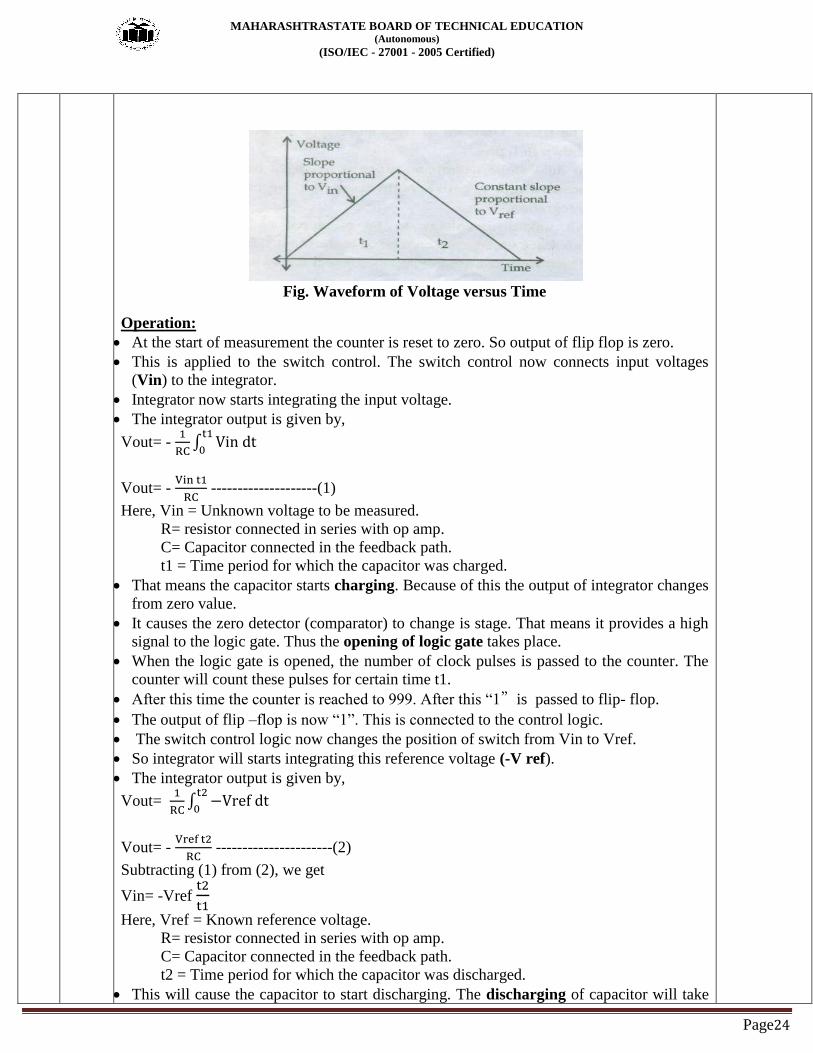
d) Explain the block diagram of Dual slope DVM. 4M
Ans: Dual Slope Integration Type DVM:
The ramp type DVM (single slope) is very simple yet has several drawbacks. The major
limitation is the sensitivity of the output to system components and clock.
The dual slope techniques eliminate the sensitivities and hence the mostly implemented
approach in DVMs. Dual slope integration technique is basically voltage to time conversion method. In
thiscase, integration is done for unknown voltage and then the same integrator is used to
dothe integration with reverse slope. So, this is called as dual slope integration method.
Fig. Block Diagram of Dual Slope Type Digital Voltmeter
2M for
diagram
2M for
explanation
MAHARASHTRASTATE BOARD OF TECHNICAL EDUCATION (Autonomous)
(ISO/IEC - 27001 - 2005 Certified)
Page24
Fig. Waveform of Voltage versus Time
Operation:
At the start of measurement the counter is reset to zero. So output of flip flop is zero.
This is applied to the switch control. The switch control now connects input voltages
(Vin) to the integrator.
Integrator now starts integrating the input voltage.
The integrator output is given by,
Vout= -
∫
Vout= -
--------------------(1)
Here, Vin = Unknown voltage to be measured.
R= resistor connected in series with op amp.
C= Capacitor connected in the feedback path.
t1 = Time period for which the capacitor was charged.
That means the capacitor starts charging. Because of this the output of integrator changes
from zero value.
It causes the zero detector (comparator) to change is stage. That means it provides a high
signal to the logic gate. Thus the opening of logic gate takes place.
When the logic gate is opened, the number of clock pulses is passed to the counter. The
counter will count these pulses for certain time t1.
After this time the counter is reached to 999. After this “1”is passed to flip- flop.
The output of flip –flop is now “1”. This is connected to the control logic.
The switch control logic now changes the position of switch from Vin to Vref.
So integrator will starts integrating this reference voltage (-V ref).
The integrator output is given by,
Vout=
∫
Vout= -
----------------------(2)
Subtracting (1) from (2), we get
Vin= -Vref
Here, Vref = Known reference voltage.
R= resistor connected in series with op amp.
C= Capacitor connected in the feedback path.
t2 = Time period for which the capacitor was discharged.
This will cause the capacitor to start discharging. The discharging of capacitor will take

MAHARASHTRASTATE BOARD OF TECHNICAL EDUCATION (Autonomous)
(ISO/IEC - 27001 - 2005 Certified)
Page25
place for the time period. The discharging path is having a constant negative slope. This
slope is as shown in Fig.
A stage will be reached at which output of integrator becomes zero.
This stage is obtained at the end of time period t2. At this instant the output of zero
detectors gets changed. This will cause the closing of logic gate.
Now the pulses from clock are not allowed to pass towards the counter. The counting
operation is completed.
Then the data from counter is passed to the digital readout for display purpose.
e) List the specification of DMM. 4M
Ans: Specifications of DMM are as follows:
1. D.C. Voltage:
Voltage range from +20V to +1000V
Accuracy about +0.03%
Resolution is about 10µV
2. AC Voltage:
Voltage range from 200mV to 750V
Accuracy is frequency dependent
Resolution: 10µV
3. Resistance:
Resistance range from 200Ω to 20 M Ω
Accuracy: +0.1% of reading
4. DC current:
Current range from +200µA to 2A
Accuracy +0.3% of reading
Resolution +0.01µA
5. A.C Current:
Range from 200µA to 2A
Accuracy depends on frequency
1M each
for any
correct 4
points
f) Give the functions any four knob of following:
i) X-shift on CRO.
ii) CT MODE Button on CRO.
iii) Symmetry knob on function generator.
iv) Level knob on function generator.
v) V/div on CRO.
vi) Mono/Dual Button on CRO.
4M
Ans: i) X-shift on CRO: Controls the horizontal position of the display i.e moves the spot across
the screen left and right. ii) CT MODE Button on CRO: To test different components
iii) Symmetry knob on function generator: Select either positive pulse/ramp or negative pulse/ramp
iv) Level knob on function generator: Determines where on the edge the trigger point occurs i.e. it’s a Variable control, selects the trigger point on the displayed waveform.
v) V/div on CRO: To control the gain/attenuation of vertical amplifier
vi) Mono/Dual Button on CRO: In DUAL, operates as a DUAL trace scope in ALT or
CHOP mode as selected.
1M each
(any
relevant
answer can
be
considered)