magstripe - paycon ii assembly
TRANSCRIPT

© 2019 Inepro B.V. All rights reserved
Work Instruction | MagStripe - PayCon II Assembly
MagStripe - PayCon IIAssembly

Version 1.0.6 Inepro B.V.http://www.inepro.com
Table of Contents
Magstripe Assembly 1

Magstripe Assembly
PartI
2 - MagStripe - PayCon II Assembly
Magstripe Assembly
Magstripe Assembly
Attention!!
Read this manual carefully before installing this device!
Main connectionBefore connecting the device to the mains, check if the mains supply voltage corresponds to the voltage printed on thetype plate of the adapter. If the mains voltage is different, consult your supplier.
GuaranteeNo guarantee can be given if safety regulations are not followed.
SecurityAlways disconnect the power supply before handling anything inside the device.
InstallationThis device has to be installed by authorised personal only.
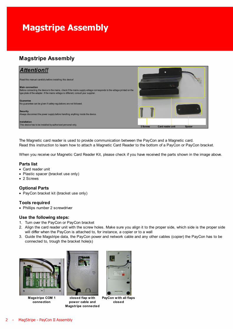
2 Screws Card reader unit Spacer
The Magnetic card reader is used to provide communication between the PayCon and a Magnetic card.Read this instruction to learn how to attach a Magnetic Card Reader to the bottom of a PayCon or PayCon bracket.
When you receive our Magnetic Card Reader Kit, please check if you have received the parts shown in the image above.
Parts list· Card reader unit· Plastic spacer (bracket use only)· 2 Screws
Optional Parts· PayCon bracket kit (bracket use only)
Tools required· Phillips number 2 screwdriver
Use the following steps:1. Turn over the PayCon or PayCon bracket2. Align the card reader unit with the screw holes. Make sure you align it to the proper side, which side is the proper side
will differ when the PayCon is attached to, for instance, a copier or to a wall3. Guide the Magstripe data, the PayCon power and network cable and any other cables (copier) the PayCon has to be
connected to, trough the bracket hole(s)
Magstripe COM 1
connection
closed flap w ith
power cable and
Magstripe connected
PayCon with all flaps
closed

R 6 - www.inepro.com - 3
4. The Magstripe card reader needs a RS232 COM port (COM port 1,2 or 3 on the PayCon main board). Connect the data cable to the first free RS232 COM port
5. Close the compartment flaps6. Make sure all the cables are in place and the compartment flaps are closed.7. Push the two screws trough the holes of your PayCon or your bracket (if you don't use a bracket, fasten them to the
PayCon and you are ready)
Copier bracket Pillar bracket PayCon
8. While holding the screws (so they don't fall out) turn the PayCon bracket back up9. Put the small plastic spacer into place
Copier bracket Pillar bracket
4 - MagStripe - PayCon II Assembly
Magstripe Assembly
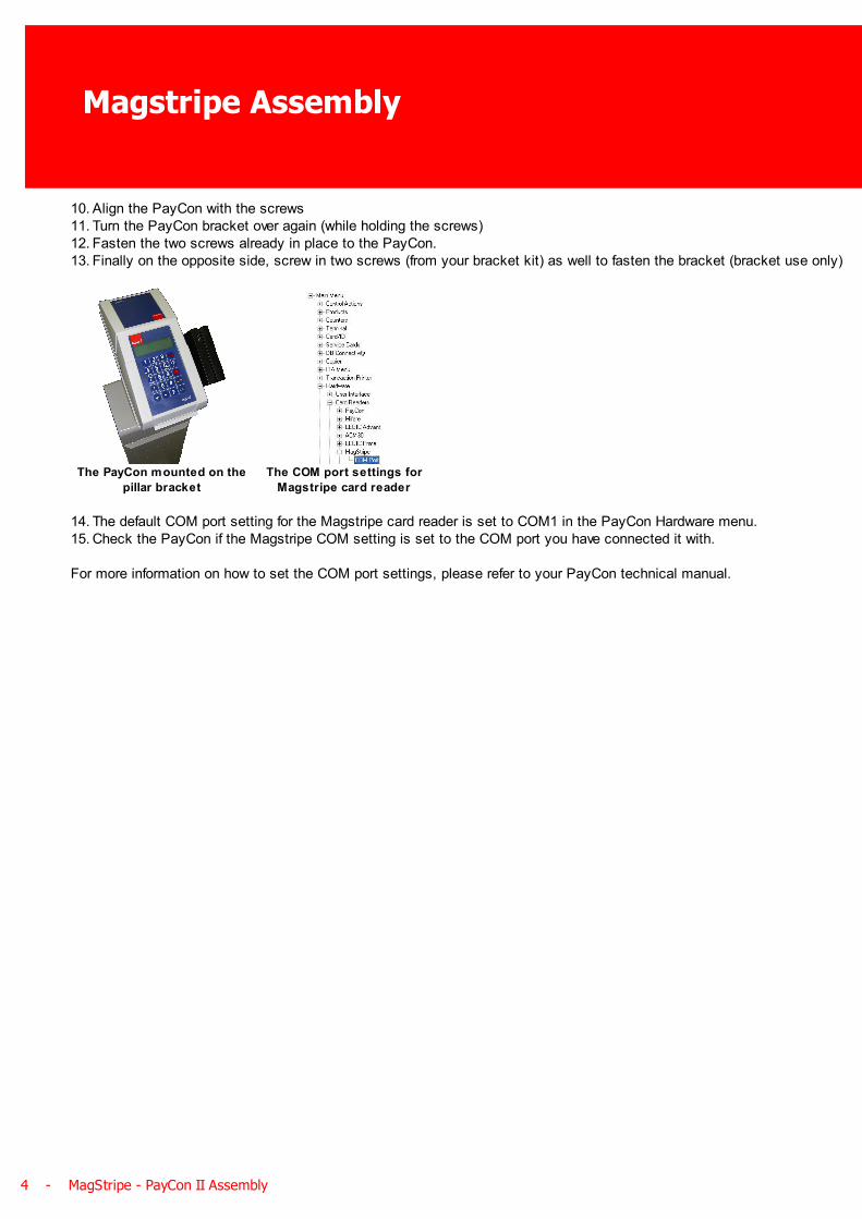
10. Align the PayCon with the screws11. Turn the PayCon bracket over again (while holding the screws)12. Fasten the two screws already in place to the PayCon.13. Finally on the opposite side, screw in two screws (from your bracket kit) as well to fasten the bracket (bracket use only)
The PayCon mounted on the
pillar bracket
The COM port settings for
Magstripe card reader
14. The default COM port setting for the Magstripe card reader is set to COM1 in the PayCon Hardware menu.15. Check the PayCon if the Magstripe COM setting is set to the COM port you have connected it with.
For more information on how to set the COM port settings, please refer to your PayCon technical manual.