magnum pro & mattoc pro/expert 2014-2016 - manitoumtb.com · manitou part number 85-0022 •...
TRANSCRIPT

2014-2016
Magnum Pro & Mattoc pro/expert

2 MATTOC/MAGNUM SERVICE MANUAL
Hayes Performance Systems 5800 W. Donges Bay Rd.
Mequon, WI 53092
Tel: 888.686.3472 Email: [email protected]
Web: www.hayescomponents.com
Hayes Components Europe Dirnismaning 20 a
85748 Garching (b. Munich) Germany
ph: +49 (0)89 203237450
Email: [email protected] Web: www.hayescomponents.com

3MATTOC/MAGNUM SERVICE MANUAL
This manual is intended to guide the user through the steps necessary to fully service and maintain the 2014-2016 Mattoc Pro/Expert, Mattoc Pro2, and Magnum Pro suspension forks.
INTRODUCTION
Suspension forks by design can contain preloaded springs, gases and fluids under extreme pressures. Warnings contained in this manual must be observed to avoid damage to fork, serious injury or even death.
We highly recommend that service to this brake be performed by a certified bicycle mechanic. Failure to follow instructions presented in this manual could lead to serious injury or death. Any questions about the servicing of this brake or the manual itself should be directed to Hayes Customer Support at:
WARNING! !
WARNING! !
Hayes Bicycle
USA
5800 W Donges Bay Road Mequon WI 53092Phone: 888.686.3472Email: [email protected]
Hayes Bicycle Europe
Dirnismaning 20 a 85748 Garching (b. Munich) GermanyPhone: +49 89 203237450Email: [email protected]
Hayes Bicycle
Asia
16F, No. 37, Sec. 3 Mincyuan E. Rd. Zhongshan District Taipei City 10476 Taiwan ROCPhone: 886-2-2518-1108

4 MATTOC/MAGNUM SERVICE MANUAL
TABLE OF CONTENTS
SECTION PAGE NUMBER
Required Tools 5
Exploded Diagram 6–8
Casting Removal & Service 10–13
Air Spring Service 14–17
Damper Service 18–22
Casting Installation 23–25
Compression Damper Install 26–29

5MATTOC/MAGNUM SERVICE MANUAL
Below is a list of tools necessary for servicing the 2014-2016 Mattoc Pro, Mattoc Pro2, Mattoc Expert, and Magnum Pro forks.
• Safety Glasses • Nitrile Gloves • Lint-Free Rags • Torque Wrench • Slickoleum™ Grease 10-Oz Tub – Manitou Part Number 20-32929 5Ml Tube – Manitou Part Number 141-33604-K001 • Semi-bath Oil, 5/40w Synthetic Manitou part number 85-0022 • 5wt Maxima Fork oil Manitou part number 85-0023 • Manitou Tool Kit Manitou part number 172-31133 (This includes the Manitou Cassette Tool, 8mm thin wall socket, and flat ground 24mm socket) • 34mm Seal Press Manitou Part Number 172-31123 • 34mm Rebuild Kit Manitou Part Number 141-28528-K008 • 8mm Hex Wrench • 2mm Hex Wrench • 20mm Socket • 22mm Box end Wrench • 12mm Box End Wrench • 12mm Socket • Ratchet • 22mm Crow’s Foot
REQUIRED TOOLS

6 MATTOC/MAGNUM SERVICE MANUAL
MAttoc Pro 26 & 27.5 Exploded view
1
2
3
4
56
7
8
9
10
MAT
TOC
PRO
26"
/27.
5"
26"
27.5
"1.
Cro
wn/
Ste
er/L
eg -
Mat
te B
lack
141-
3099
6-K
011
141-
3099
6-K
014
1. C
row
n/S
teer
/Leg
- W
hite
141-
3099
6-K
012
141-
3099
6-K
015
1. C
row
n/S
teer
/Leg
- M
atte
Red
141-
3099
6-K
013
141-
3099
6-K
016
2. C
ompr
essi
on D
ampe
r Ass
embl
y14
1-30
996-
K00
114
1-30
996-
K00
1
3. C
artri
dge
Reb
ound
Dam
per A
ssem
bly
141-
3099
6-K
003
141-
3099
6-K
017
4. B
ushi
ng K
it14
1-30
996-
K01
914
1-30
996-
K01
9
5. O
uter
Cas
ting
- QR
15 -
Mat
te B
lack
141-
3099
6-K
008
141-
3099
6-K
008
5. O
uter
Cas
ting
- QR
15 -
Whi
te14
1-30
996-
K00
914
1-30
996-
K00
9
5. O
uter
Cas
ting
- QR
15 -
Mat
te R
ed14
1-30
996-
K01
014
1-30
996-
K01
0
6. Q
R15
Axl
e14
1-28
131-
K01
614
1-28
131-
K01
6
7. Q
R15
Har
dwar
e14
1-28
131-
K02
414
1-28
131-
K02
4
8. S
eal K
it14
1-30
996-
K00
714
1-30
996-
K00
7
9. C
ompr
essi
on R
od A
ssem
bly
141-
3099
6-K
005
141-
3099
6-K
005
10. T
op C
ap14
1-30
996-
K00
614
1-30
996-
K00
6
11. R
ebou
nd K
nob/
Air C
ap A
ssem
bly
141-
3215
5-K
016
141-
3215
5-K
016
MC
2 R
epla
cem
ent K
nob
Kit
141-
3215
5-K
015
141-
3215
5-K
015
Dec
al K
it14
1-30
996-
K02
014
1-30
996-
K02
1
PAR
T D
ESC
RIP
TIO
NPA
RT
NU
MB
ER
141-
3397
8-K
009
141-
3397
8-K
009

7MATTOC/MAGNUM SERVICE MANUAL
Magnum Pro 27.5 & 29+ Exploded view
12
3
4
5
6
7
8
89
10
11
MA
GN
UM
PRO
27.
5” &
29”
27.5
"29
"1.
Cro
wn/
Stee
r/Le
g - 8
0/10
014
1-32
155-
K017
141-
3215
5-K0
011.
Cro
wn/
Stee
r/Le
g - 1
2014
1-32
155-
K002
1. C
row
n/St
eer/
Leg
- 120
/140
141-
3215
5-K0
182.
MC2
Kno
b Ki
t14
1-32
155-
K015
141-
3215
5-K0
153.
MC2
Com
pres
sion
Dam
per -
Incl
udes
Kno
b14
1-30
996-
K001
141-
3099
6-K0
014.
Reb
ound
Dam
per A
ssem
bly
- 80/
100
141-
3215
5-K0
2014
1-32
155-
K005
4. R
ebou
nd D
amep
r Ass
embl
y - 1
2014
1-32
155-
K006
4. R
ebou
nd D
amep
r Ass
embl
y - 1
20/1
4014
1-32
155-
K021
5. S
eal K
it14
1-30
996-
K007
141-
3099
6-K0
076.
Out
er C
asng
(inc
lude
s sea
ls &
bus
hing
s)14
1-32
155-
K019
141-
3215
5-K0
037.
QR1
5 Ax
le14
1-32
155-
K011
141-
3215
5-K0
118.
Reb
ound
Adj
ust K
nob/
Air C
ap K
it14
1-32
155-
K016
141-
3215
5-K0
169.
QR1
5 Ax
le H
ardw
are
141-
2813
1-K0
2414
1-28
131-
K024
10. A
ir Sp
ring
Asse
mbl
y - 8
0/10
014
1-32
155-
K022
141-
3215
5-K0
0810
. Air
Sprin
g As
sem
bly
- 120
141-
3215
5-K0
0910
. Air
Sprin
g As
sem
bly
- 120
/140
141-
3215
5-K0
2311
. Adj
usta
ble
Air C
ap14
1-32
155-
K004
141-
3215
5-K0
04De
cal K
it14
1--K
024
141-
3215
5-K0
13
PART
DES
CRIP
TIO
NPA
RT N
UM
BER
141-
3397
8-K0
1314
1-33
978-
K013

8 MATTOC/MAGNUM SERVICE MANUAL
MAttoc Expert 26 & 27.5 Exploded view
1
2
3
4
56
7
89
10
26"
27.5
"1.
Cro
wn/
Ste
er/L
eg -
Mat
te B
lack
141-
3099
6-K
011
141-
3099
6-K
014
1. C
row
n/S
teer
/Leg
- W
hite
141-
3099
6-K
012
141-
3099
6-K
015
1. C
row
n/S
teer
/Leg
- M
atte
Red
141-
3099
6-K
013
141-
3099
6-K
016
2. C
ompr
essi
on D
ampe
r Ass
embl
y14
1-30
996-
K00
214
1-30
996-
K00
2
3. R
ebou
nd D
ampe
r Ass
embl
y14
1-30
996-
K00
414
1-30
996-
K01
8
4. B
ushi
ng K
it14
1-30
996-
K01
914
1-30
996-
K01
9
5. O
uter
Cas
ting
- QR
15 -
Mat
te B
lack
141-
3099
6-K
008
141-
3099
6-K
008
5. O
uter
Cas
ting
- QR
15 -
Whi
te14
1-30
996-
K00
914
1-30
996-
K00
9
5. O
uter
Cas
ting
- QR
15 -
Mat
te R
ed14
1-30
996-
K01
014
1-30
996-
K01
0
6. Q
R15
Axl
e14
1-28
131-
K01
614
1-28
131-
K01
6
7. Q
R15
Har
dwar
e14
1-28
131-
K02
414
1-28
131-
K02
4
8. S
eal K
it14
1-30
996-
K00
714
1-30
996-
K00
7
9. C
ompr
essi
on R
od A
ssem
bly
141-
3099
6-K
005
141-
3099
6-K
005
10. T
op C
ap14
1-30
996-
K00
614
1-30
996-
K00
6
11. R
ebou
nd K
nob/
Air C
ap A
ssem
bly
141-
3215
5-K
016
141-
3215
5-K
016
MC
2 R
epla
cem
ent K
nob
Kit
141-
3215
5-K
015
141-
3215
5-K
015
Dec
al K
it14
1-30
996-
K02
014
1-30
996-
K02
1
PAR
T D
ESC
RIP
TIO
NPA
RT
NU
MB
ER
11

9MATTOC/MAGNUM SERVICE MANUAL
Limited Warranty:HAYES warrants its products to be free from defects in materials or workmanship under normal intended use for a period of one year (two years in European Union countries) from the date of purchase, subject to normal wear and tear. Unless otherwise prohibited by law, any such defective products will be repaired or replaced at the option of HAYES when received with proof of purchase, freight prepaid. This warranty does not cover breakage, bending, or damage that may result from crashes or falls. This warranty does not cover any defects or damage caused by alterations or modifications of HAYES products or by normal wear, accidents, improper maintenance, damages caused by the use of HAYES products with parts of different manufacturers, improper use or abuse of the product, application or uses other than those set forth in the HAYES instruction manual or failure to follow the instructions contained in the applicable HAYES instruction manual. Instruction manuals can be found on-line at www.hayescomponents.com. Any modifications made by the BUYER or any subsequent user will render the warranty null and void. This warranty does not apply when the serial number or production code has been deliberately altered, defaced or removed from the product. The cost of normal maintenance or replacement of service items, which are not defective, shall be the BUYER’s responsibility. If permitted by local law, this warranty is expressly in lieu of all other warranties (except as to title), express or implied, and in particular and without limitation HAYES disclaims the implied warranties of merchantability or fitness for purpose If for any reason warranty work is necessary, return the component to the place of purchase or contact your dealer or local HAYES distributor. In the USA, contact HAYES for a return authorization number (RA#) at (888) 686-3472. At that time, instructions for repair, return, or replacement shall be given. Customers in countries other than the USA should contact their dealer or local HAYES distributor.
Limitation of Liability.Unless required by mandatory law, HAYES shall not be liable for any incidental, indirect, special or consequential damages.
This warranty does not apply to normal wear and tear. Wear and tear parts are subject to damage through normal use, failure to service according to recommendations or riding in conditions other than recommended. The cost of normal maintenance or replacement of service items, which are not defective, shall be paid for by the original purchaser. Wear and tear parts that will not be replaced under warranty include but are not limited to the following:
- Bushings- Rear Shock Mount Hardware- Handlebar grips- Tubeless Valves
- Dust Seals- Fork and Shock air Seals and/or O-rings- Bearings- Upper Stanchion Tubes
- Stripped or worn bolts- Remote Lockout Cable- Gloves- Lower Stanchion Tubes(Dorado)
HAYES PERFORMANCE SYSTEMS WARRANTY

10 MATTOC/MAGNUM SERVICE MANUAL
CASTING REMOVAL & SERVICE
1 Remove rebound knob using a 2mm Hex wrench.
Insert a 8mm Hex wrench into the end of the rebound rod and loosen clockwise until rebound rod disengages from the casting threads.
2
3 Unscrew air cap and depress Schrader Valve a few times to ensure all air is released.

11MATTOC/MAGNUM SERVICE MANUAL
Using the Mattoc 8mm Thin Wall Socket, turn the compression rod clockwise until compression rod is disengaged from the casting threads.
Remove casting from fork. It is recommended this be done over a drain pan as the lower casting contains semi-bath oil. Allow oil in casting to drain out before continuing to next step.
4
5
6 Using a downhill tire lever or similar tool, gently pry the dust seals out of the casting.
12 MATTOC/MAGNUM SERVICE MANUAL
CASTING REMOVAL & SERVICE
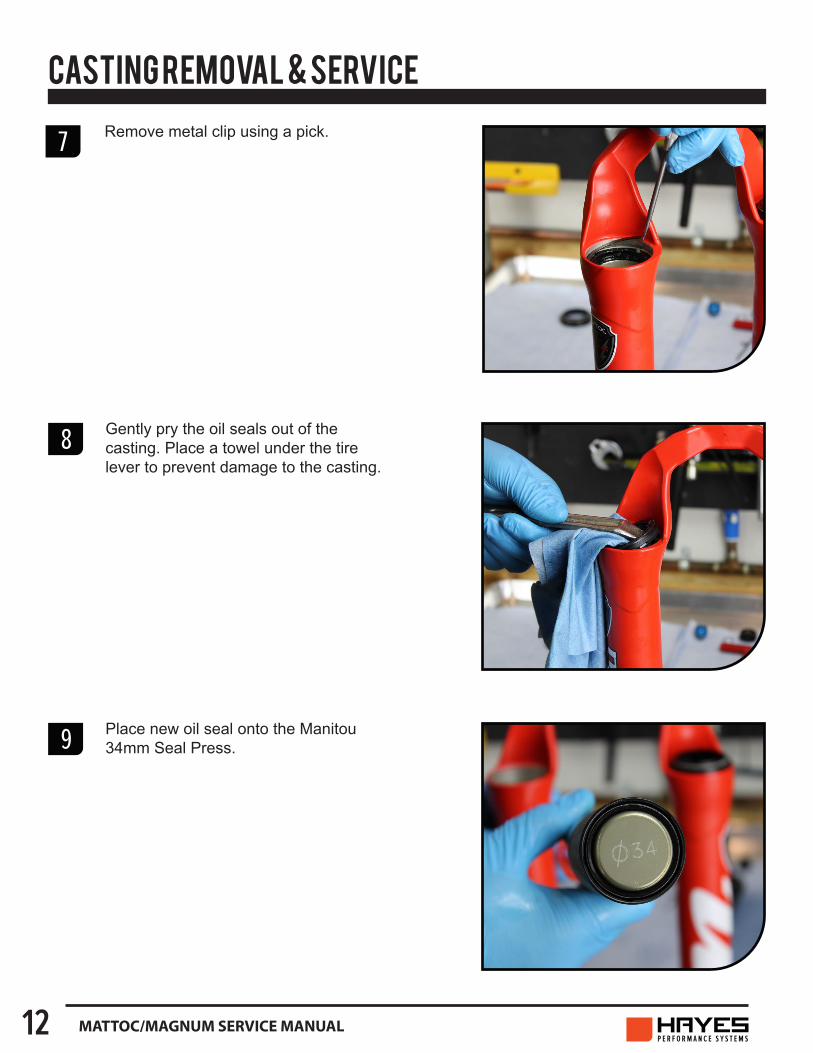
Gently pry the oil seals out of the casting. Place a towel under the tire lever to prevent damage to the casting.
Place new oil seal onto the Manitou 34mm Seal Press.
8
9
7 Remove metal clip using a pick.

13MATTOC/MAGNUM SERVICE MANUAL
CASTING REMOVAL & SERVICE
Using the Manitou 34mm Seal Press or large socket press in the oil seals.
Reinstall metal clips.
Using the Manitou 34mm Seal Press or large socket press in the dust seals.
10
11
12

14 MATTOC/MAGNUM SERVICE MANUAL
AIR SPRING SERVICE
1
2
3
Make sure the air is released from the fork. Depress Schrader valve a few times to ensure all air is released.
Remove IVA using a 24mm socket.
Pull IVA straight out. The early Mattoc forks will have the cap shown on the right. Mattoc 2 and Magnum Pro forks will have the IVA assembly shown on the left.

15MATTOC/MAGNUM SERVICE MANUAL
AIR SPRING SERVICE
4
5
Remove Air Spring Assembly, clean with isopropyl, and re-grease.
Once the air spring assembly is removed clean the inside of the stanchion with isopropyl alcohol and a lint free towel (Be careful to not scratch the inner surface of the stanchion). Inspect the inside and outside of the stanchion for scratches or other damage.
3 Invert the fork and use Manitou cassette tool and adjustable wrench to unthread the air spring assembly from the stanchion.

16 MATTOC/MAGNUM SERVICE MANUAL
6
7
Liberally grease the piston quad seal and outer surface with Slickoleum™ grease. Add 8cc’s of Slickoleum™ grease to the top of the air piston.
Add Slickoleum™ grease to the stanchion threads before inserting the air spring assembly. Spread grease across entire thread surface.
AIR SPRING SERVICE
8 Install air spring assembly into stanchion. Using a 26mm crow’s foot and Manitou cassette tool, torque to spec.
Torque Specs • Mattoc Pro & Magnum Pro 60-80 in lb [6.8-9.0 N m] • Mattoc Expert 80-100 in lb [9.0-11.3 N m]

17MATTOC/MAGNUM SERVICE MANUAL
10
Install air cap onto stanchion. Tighten to 60-80 in lb [6.8-9.0 N m].
Attach a shock pump and inflate air leg to 60PSI. This will aid in installing the casting later.
AIR SPRING SERVICE
9

18 MATTOC/MAGNUM SERVICE MANUAL
DAMPER SERVICE
1
2
Using a 2mm Hex wrench remove the screw of the MC2 knob.
Note: Be sure to hold the knob still while removing the screw/nut. These tend to move and can damage the damper if the knob is over turned.
Remove the black high speed compression knob while keeping the silver HBO knob in place.
Note: Be sure to hold the knob still while removing the screw/nut. These tend to move and can damage the damper if the knob is over turned.

19MATTOC/MAGNUM SERVICE MANUAL
DAMPER SERVICE
4
3 With a 13mm socket, unthread the exposed nut and remove the red low speed adjustment knob.
Note: Be sure to hold the knob still while removing the screw/nut. These tend to move and can damage the damper if the knob is over turned.
Remove the sliver spacer that was under the red low speed adjustment knob.

20 MATTOC/MAGNUM SERVICE MANUAL
DAMPER SERVICE
5
6
Use the Manitou cassette tool and adjustable wrench to unthread the compression damper assembly from the stanchion.
Remove compression damper assembly from the stanchion.
The Mattoc Pro will have the rebound damper assembly style shown on the top. The Mattoc Expert will have the assembly on the bottom.

21MATTOC/MAGNUM SERVICE MANUAL
7
7
8
DAMPER SERVICE
Using a Manitou cassette tool and adjustable wrench, unthread the rebound damper assembly from the fork stanchion.
Remove rebound damper assembly from the fork. Once the damper assembly is removed, clean the inside of the stanchion with isopropyl alcohol and a lint free towel. Inspect the inside and outside of the stanchion for scratches and other damage. Inspect rebound damper for damage as well. Replace if necessary.
Pour Fork Oil into a catch pan.

22 MATTOC/MAGNUM SERVICE MANUAL
The Mattoc and Magnum Pro will have the half cartridge design rebound damper shown on the top. The Mattoc Expert will have the in-leg design shown on the bottom.
9 Use a 26mm crow’s foot, Manitou cassette tool, and torque wrench to install the rebound damper assembly.
Torque Specs • Mattoc Pro & Magnum Pro 60-80 in lb [6.8-9.0 N m] • Mattoc Expert 80-100 in lb [9.0-11.3 N m]
DAMPER SERVICE

23MATTOC/MAGNUM SERVICE MANUAL
CASTING INSTALL
1
2
3
Before filling the fork with fork oil and installing the MC2 compression damper, we must first install the casting. This ensures a correct oil level. First apply a generous amount of Slickoleum™ grease to the oil seal/dust seal area of the casting.
Fill the air chamber with air (60PSI). This will extend the air spring assembly and make casting installation easier.
Fully extend the rebound damper rod.

24 MATTOC/MAGNUM SERVICE MANUAL
CASTING INSTALL
4
5
6
Slide casting onto the stanchion assembly. Only slide the casting down about halfway at this point. Take care that the seal lips do not fold over upon installation.
Insert semi-bath into each casting leg. Once the semi-bath is in the legs slide the casting the rest of the way onto the stanchion assembly.
Semi-bath Amounts • Mattoc Pro, Pro2, and Expert 7cc in each leg • Magnum Pro 15cc in each leg
Using an 8mm hex wrench tighten the rebound damper rod to 35–40 in lb [3.95–4.5 N m] by turning them counter-clockwise. Do not overtighten, doing so can damage the end of the rods.

25MATTOC/MAGNUM SERVICE MANUAL
CASTING INSTALL
8
7
Using the Manitou 8mm Thin Wall Socket tighten the compression rod to 35–40 in lb [3.95–4.5 N m] by turning them counter-clockwise. Do not overtighten, doing so can damage the end of the rods.
Install the rebound knob using a 2mm Hex wrench. Add a small drop of blue Loctite to the screw before installation to prevent the screw from backing out during riding.

26 MATTOC/MAGNUM SERVICE MANUAL
COMPRESSION DAMPER INSTALL
1
2
3
Pour 5wt Maxima fork oil into the damper leg. Fill it up about ¾ full.
Place a lint-free towel over the opening in the damper leg and compress the fork 10-15 times.
Pour additional 5wt fork oil into the damper leg until the oil height (space from the top of the damper leg to the top of the oil) is set at the proper level. See following page for the correct oil height depending on compression damper type and fork travel. An oil height setting tool used for motorcycle forks similar to the one pictured makes this job easier.

27MATTOC/MAGNUM SERVICE MANUAL
oil height chart 2016/2017
match compm30 (abs+)m30 (kwik toggle, 80/100mm)
circus sport (ffd)circus comp/expertmarvel comp/expertmarvel prominute comp/expertminute promachete (kwik toggle)machete (abs+)magnum compmagnum promattoc compmattoc expertmattoc pro
83mm
dorado (see dorado service guide)
83mm92mm
83mm87mm87mm75mm87mm75mm87mm87mm87mm75mm87mm80mm75mm/ /
oilheight(refers to the air space between the top of the oil and top of the fork leg)
1. oil height is set with compression damper removed.2. oil height is set with fork fully extended and casting installed.
note
tech support: [email protected] tech support: [email protected]
fork model oil height
m30 (kwik toggle, 120mm) 97mm
COMPRESSION DAMPER INSTALL

28 MATTOC/MAGNUM SERVICE MANUAL
4
5
6
Insert compression damper into the damper leg. Ensure the damper is set in the unlocked position when installing.
Using a crow’s foot, Manitou cassette tool, and torque wrench, tighten down the MC2 at a torque of 60–80 in lb [6.8–9.0 N m].
Place the silver spacer onto the MC2 damper as shown.
COMPRESSION DAMPER INSTALL

29MATTOC/MAGNUM SERVICE MANUAL
7
8
9
Place high speed and HBO knob assembly onto the red low speed adjustment knob. Tighten down screw with 2mm Hex wrench.
Note: Be sure to hold the knob still while removing the screw/nut. These tend to move and can damage the damper if the knob is over turned.
Clean fork and use a shock pump to set to desired pressure. Lightly pull the casing away from the CSA as you add air. Pressure chart below for reference.
COMPRESSION DAMPER INSTALLPlace red low speed adjustment knob onto damper assembly. With a 13mm socket, tighten down the nut finger tight
Note: Be sure to hold the knob still while removing the screw/nut. These tend to move and can damage the damper if the knob is over turned.

WWW. MANITOUMTB.COM WWW.HAYESCOMPONENTS.COM 5800 W DONGES BAY ROAD MEQUON WI 53092