magnets for cyclotrons - cern · magnets for cyclotrons s. zaremba iba s.a., b-1348...
TRANSCRIPT
Magnets for cyclotrons
S. Zaremba IBA S.A., B-1348 Louvain-la-Neuve, Belgium
Abstract Different design aspects of cyclotrons and magnets for cyclotrons are reviewed. The cyclotron magnet design should be considered as an iterative process starting from a simple model that requires the vision of the complete cyclotron and the possibility of integration of all subsystems. Detailed calculations of 2-D and 3-D models follow to optimize the cyclotron magnet and cyclotron.
1 Introduction Sometimes in the past the design of a cyclotron was reduced to cyclotron magnet calculations. This resulted in difficulties to install other cyclotron subsystems and famous discussions between cyclotron specialists during International Cyclotron Conferences (… next time I will design the RF system first and later you will design your magnet around it…) [1].
This error should be avoided. For this reason, different design aspects of cyclotron magnets and cyclotrons are reviewed at first. It is assumed that the cyclotrons considered here are the fixed-field, fixed-frequency machines with an azimuthally varying magnetic field (field hills and valleys) provided by the magnet sectors (poles) as described in classical textbooks like Ref. [2] or available on the internet for personal use [3].
The cyclotron magnet design should be considered as an iterative process starting from a very simple model, but taking into account the vision of the complete cyclotron. The different sub-systems of a cyclotron like
– RF (radiofrequency) system
– vacuum pumping system
– internal ion source or injection system
– extraction system or internal target
– diagnostic system
interact with each other and always interact with the magnet.
The initial crude cyclotron magnet design should be confirmed and iteratively refined by 2-D model calculations. Very detailed 3-D models are developed as the next step and the time-consuming iterative optimization of the cyclotron magnet follows.
Without the vision of a complete cyclotron one can be forced to restart the cyclotron magnet design again.
2 General trends and consequences Remarks presented here reflect more the industrial than the scientific point of view. Over the last 19 years (1986–2005) the IBA company has produced and sold more than 150 cyclotrons of 11 types that accelerate different ions for kinetic energies between 3 and 235 MeV. The statistics are perhaps not yet
253
sufficient but general trends concerning the purpose of purchased cyclotrons can easily be established. The customers of IBA have never requested the cyclotron only for nuclear physics experiments. The priority of all customers is focused on specific applications like a production of many radioisotopes requiring the cyclotrons of low energy, i.e., protons/deuterons below 40 MeV. Sometimes the cyclotrons are destined for a single task like single radioisotope production (palladium Pd or thallium Tl) or an acceleration of protons for proton therapy to the fixed kinetic energy of 230 MeV. Pure nuclear physics experiments are very rare but many low-energy cyclotrons are used for research in radiochemistry.
These observed general trends generate requirements and have consequences for cyclotron end-users and for cyclotron designers that can be grouped in descending order of importance:
– Very important for end-users and for cyclotron designers
Low radiation doses for the personnel; everybody wants a cyclotron design ensuring very low beam losses, cyclotron parts easy to mount and dismount, parts made from the materials that are difficult to activate and parts from the material with the minimum quantity of impurities having a large cross-section to possible nuclear reactions.
Reliability, cost and simplicity; everybody wants a cyclotron that is cheap, has an unexpected down-time close to zero (the mean time between failure MTBF as large as possible) and can be used by low-skilled persons without too much technical background. The requirements of simplicity can also be extended by a remote or unattended automatic operation of the cyclotron.
– Important for end-user and interesting or challenging for cyclotron designers
Occupied space and weight; practically all end-users are interested by cyclotrons that have a minimum possible foot-print and enter into a vault that has height only slightly higher than that of the cyclotron. This diminishes the cost of bunker or building where the cyclotron is installed. On the other hand, cyclotron designers always consider it a point of honour to design a cyclotron that is smaller than other machines. This is also interesting due to the recent increase of prices of iron used for the cyclotron magnet production.
Beam quantity and beam quality; radioisotope producers are mainly interested by the quantity of produced radioisotopes and the beam quality (i.e., the beam emittance) is frequently irrelevant for them. The end-user is happy if the beam enters the target without destroying the target window due to too small beam emittance (hot spot) or without any losses on collimators due to too large emittance. The cyclotron designers will always fight to obtain the smallest beam emittance possible because it guarantees the smallest beam losses during beam acceleration and beam extraction from the cyclotron.
– Less important for end-users and still interesting or challenging for cyclotron designers
Consumed electric power; the cyclotron designers always try to minimize the electric power necessary for the magnet and all cyclotron subsystems. It is also quite frequent that the electric power dissipated in cyclotron magnet coils is much smaller than the sum of electric power of other elements. Cyclotron end-users producing the radioisotopes are less interested by this subject and they have a possibility to reflect the price of electricity in the final price of distributed radioisotopes. The end-users of proton therapy systems are more interested by this subject due to the consumed power of classical cyclotron magnet coils reaching 200 kW that increases the interest for superconducting cyclotron.
S. ZAREMBA
254
– Not very important for end-users and frustrating for cyclotron designers
Versatility of cyclotron; the end-users do not require cyclotrons able to accelerate many types of ions to the different kinetic energies. Two types of accelerated ions (different charge state/mass ratio) are frequently demanded, e.g., the protons and the D ions with the fixed kinetic energy at extraction. Cyclotron designers dream about the design of versatile cyclotrons accelerating any type of ions.
3 Cyclotron magnet functions and qualities After general remarks concerning the cyclotrons we go to the cyclotron magnet that constitutes the essential part of each cyclotron. A well-designed cyclotron magnet should ensure:
– isochronous magnetic field during acceleration;
– the magnetic field that provides the axial (vertical) and the radial focusing of a beam during acceleration;
– the magnetic field that guarantees an operation point (for cyclotrons it is more operation curve) away from resonance(s) or the fast passage of beam through resonance zones;
– last but not least, already mentioned and very important, the possibility to install all cyclotron subsystems.
The essential information and equations describing the isochronous magnetic field in the cyclotron have been extensively presented during another lecture of this CERN Accelerator School [4]. The most important is that the isochronous magnetic field compensates the relativistic mass increase of ions during acceleration and consequently ensures the synchronism of accelerated ions with the phase of the RF system. The isochronous magnetic field shape can be obtained using many methods. Usually cyclotron magnet designers apply a combination of a few methods to obtain the desired effects. The methods of magnetic field isochronization are used during the calculations of cyclotron magnets and also during the production of real cyclotron magnets. In reality the subtraction of iron from magnet pieces is easier than the addition. This is the main difference between the theoretical calculations and the real production of cyclotron magnets. It is worth recapitulating here how a cyclotron magnet is produced.
3.1 Steel purchase
The steel industry knows (officially) nothing about the magnetic properties of iron. Much more important and easy to quantify are the mechanical parameters such as hardness, strength, stiffness or ductility and the chemical composition of steel. The mechanical parameters are nearly irrelevant for the cyclotron magnet designer. On the other hand the chemical properties are extremely important because they influence the magnetic properties of steel. Therefore the cyclotron magnet designer has to know the chemical composition of steel. The general rule is that the better magnetic properties of steel are obtained when the steel contains as much iron (Fe) as possible and a lower percentage of carbon (C). The steel, with very good magnetic properties, has less than 0.03% of carbon and requires special procedures in a steel plant. The good magnetic steel contains about 0.10% of carbon and is often available off the shelf. Other impurities also influence the magnetic properties. It is well known that sulphur (S) and phosphorus (P) quickly deteriorate the magnetic properties of steel so their percentage should always be as low as possible. The impurities of the other chemical elements like Si, Cr, Cu, Sn, Mn, Ni, Mo, Al, N, V, Ti or Nb may be present in steel and there is an interest to keep their percentage as low as possible as well.
MAGNETS FOR CYCLOTRONS
255

3.2 Steel processing
Casting: mainly used to obtain steel pieces thicker than when rolled or forged. The magnetic properties of steel are dependent on a cooling process that has to be very slow to avoid cracks and to allow the development of micro crystalloid structures becoming later the magnetic domains. The casting is expensive because a mold is required and very often this mold is used only once.
Rolling: can be considered as a standard procedure. It may slightly improve the magnetic properties of steel. It may introduce cracks in a steel volume when done at a wrong temperature. This could be revealed later during steel machining, sometimes creating serious problems.
Forging: generally improves the magnetic properties of steel and removes possible defects (cracks, voids) from the steel but is more expensive.
3.3 Steel machining
Gas-cutting: used to roughly cut the pieces of a cyclotron magnet.
Turning and milling: used to obtain the final, very precise shape of each piece of cyclotron magnet. It guarantees that a new cyclotron magnet will have the same geometrical shape as the previous cyclotron magnet but does not guarantee at all the same magnetic field on account of the differences of magnetic properties of steel, due to the imperfections in the volume of steel, the different temperatures of processing and machining, mechanical tolerances and errors. This clearly indicates that each cyclotron magnet is unique and therefore it requires the iterative procedure of magnetic field measurements and mechanical corrections until the magnetic field is sufficiently isochronous. At this point all the methods of magnetic field isochronization are really very useful.
4 Methods of obtaining an isochronous magnetic field
4.1 Increase the hill angle/valley angle ratio
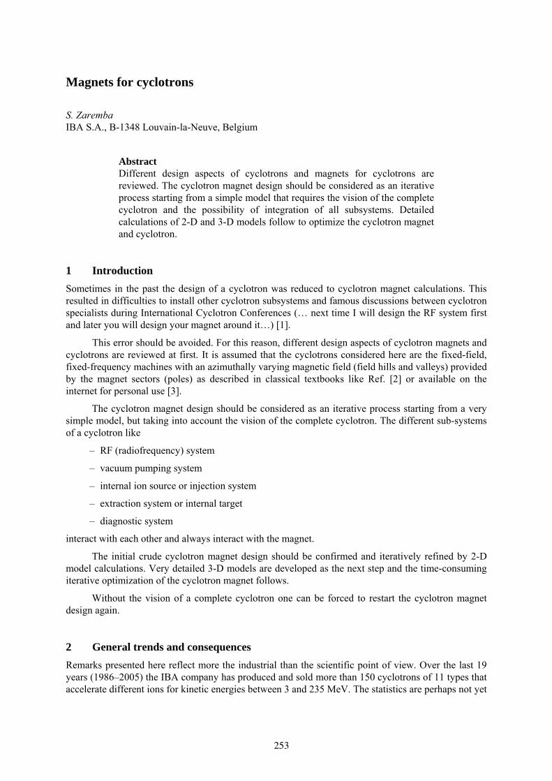
The increase of the azimuthal length of poles is the easiest way to create the average magnetic field that increases with radius like the isochronous magnetic field does. At the same time it is necessary to observe the behaviour of a flutter [4] that determines the focusing properties of magnetic field. The maximum flutter usually corresponds to the hill angle equal to the valley angle on the one rotational symmetry period of the cyclotron so this is the most natural choice. RF cavities often fill the valleys of cyclotrons with a very small gap between poles. In this case the increase of the hill angle/valley angle ratio may diminish the kinetic energy gain per turn of accelerated ions so again the valley angle can not be diminished without reasons. Figure 1 presents the cyclotron poles where the hill angle/valley angle ratio increases close to the outer radius of each magnet pole.
4.2 Shimming of pole edges or shims
This method is the most frequently used to create the isochronous magnetic field for the fixed energy one or two accelerated ion machines. From the algebra of relativity it is easy to find the relations between the ion velocity V, the ion momentum p, the ion total energy E or their relativistic dimensionless equivalents: the velocity as the fraction of the light velocity c: β = V/c, total energy in the units of the rest energy E0: γ = E/E0, momentum in the units of the rest mass multiplied by the velocity of light: η = p/(m0*c) . One of these relations is d η/η = γ2 · d β/β . This last relation at the chosen radius r of the cyclotron magnet can be presented using the average magnetic field at this radius B(r) and the accelerated particle rotation frequency fp(r) as:
)()(
)()()(
p
p2
rfrf
rrBrB Δ
=Δ γ .
S. ZAREMBA
256
1
1
22
3
3
Fig. 1: The upper part of IBA C18/9 cyclotron magnet that shows the example of different methods to obtain the isochronism of the magnetic field: (1) increase hill angle/valley angle ratio close to outer radius of pole; (2) shimming of one pole edge, other pole edge has fixed shape; (3) shimming and/or movement of movable inserts in two opposite valleys
The equation above is used to calculate the corrections of the magnetic field from the results of equilibrium orbit [4] calculations. Then the corrections of the magnetic field can be recalculated according to the quantity of iron to be removed or added to all magnet poles to obtain the isochronous field. To add iron is possible in the theory. In practice the iron is usually locally subtracted by milling. The possible addition of the magnetic field is global (for all radii) and performed by the increase of current in the cyclotron magnet coils. Figure 1 presents this situation. The one lateral pole edge of each pole is unchanged and a chamfer on this pole edge is identical for all radii. The second lateral pole edge of each pole is modified to obtain the isochronous magnetic field. The chamfer of this lateral pole edge varies along the radius. Sometimes pole edges can be removable and divided in two or three pieces to facilitate handling.
4.3 Decrease the gap between poles as a function of radius
This method is based on the redistribution of magnetic flux. It is easy to implement and well suited for the initial configuration of magnet poles. Then other described methods would be preferred to obtain the isochronism of the field. The example of this method is presented in Fig. 2. The gap as a function of radius between magnet poles in IBA C235 cyclotron is described by the ellipse given below, with the minimum gap between poles of 9 mm. The minimum gap is necessary because the ions need some space for acceleration and extraction.
5.4148
)(1120 min2
2
2
2
==+ gaphalfgaphalfr .
MAGNETS FOR CYCLOTRONS
257
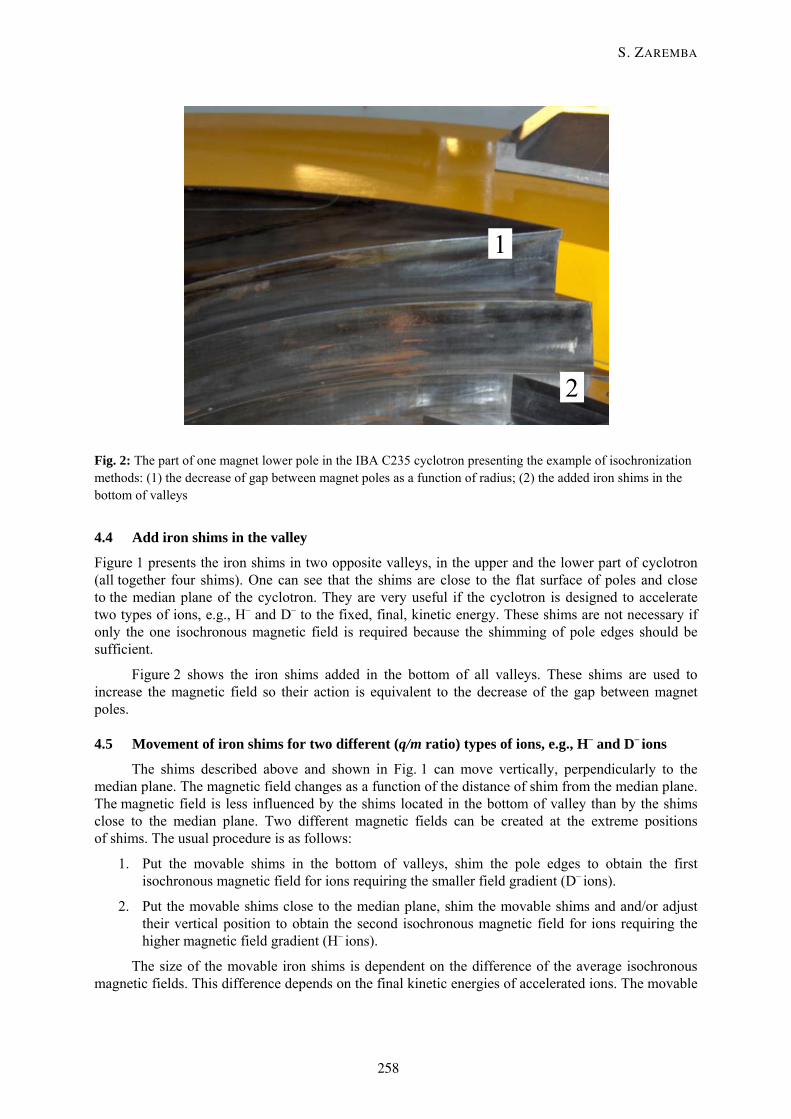
Fig. 2: The part of one magnet lower pole in the IBA C235 cyclotron presenting the example of isochronization methods: (1) the decrease of gap between magnet poles as a function of radius; (2) the added iron shims in the bottom of valleys
4.4 Add iron shims in the valley
Figure 1 presents the iron shims in two opposite valleys, in the upper and the lower part of cyclotron (all together four shims). One can see that the shims are close to the flat surface of poles and close to the median plane of the cyclotron. They are very useful if the cyclotron is designed to accelerate two types of ions, e.g., H– and D– to the fixed, final, kinetic energy. These shims are not necessary if only the one isochronous magnetic field is required because the shimming of pole edges should be sufficient.
Figure 2 shows the iron shims added in the bottom of all valleys. These shims are used to increase the magnetic field so their action is equivalent to the decrease of the gap between magnet poles.
4.5 Movement of iron shims for two different (q/m ratio) types of ions, e.g., H– and D– ions
The shims described above and shown in Fig. 1 can move vertically, perpendicularly to the median plane. The magnetic field changes as a function of the distance of shim from the median plane. The magnetic field is less influenced by the shims located in the bottom of valley than by the shims close to the median plane. Two different magnetic fields can be created at the extreme positions of shims. The usual procedure is as follows:
1. Put the movable shims in the bottom of valleys, shim the pole edges to obtain the first isochronous magnetic field for ions requiring the smaller field gradient (D– ions).
2. Put the movable shims close to the median plane, shim the movable shims and and/or adjust their vertical position to obtain the second isochronous magnetic field for ions requiring the higher magnetic field gradient (H– ions).
The size of the movable iron shims is dependent on the difference of the average isochronous magnetic fields. This difference depends on the final kinetic energies of accelerated ions. The movable
1
2
S. ZAREMBA
258
shims are not attached to the other elements of the magnetic circuit so they are much less efficient than, for example, the shimming of pole edges. The magnetic field isochronization using the movable shims can only be applied for the low kinetic energy machines. Also the rotational symmetry of poles and valleys is different than the symmetry of shims. In this way the imperfect second harmonic of the magnetic field can be created that may deteriorate the beam quality when the amplitude and/or the position of imperfection is wrong.
4.6 Correction trim coils
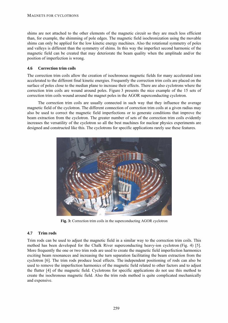
The correction trim coils allow the creation of isochronous magnetic fields for many accelerated ions accelerated to the different final kinetic energies. Frequently the correction trim coils are placed on the surface of poles close to the median plane to increase their effects. There are also cyclotrons where the correction trim coils are wound around poles. Figure 3 presents the nice example of the 15 sets of correction trim coils wound around the magnet poles in the AGOR superconducting cyclotron.
The correction trim coils are usually connected in such way that they influence the average magnetic field of the cyclotron. The different connection of correction trim coils at a given radius may also be used to correct the magnetic field imperfections or to generate conditions that improve the beam extraction from the cyclotron. The greater number of sets of the correction trim coils evidently increases the versatility of the cyclotron so all the best machines for nuclear physics experiments are designed and constructed like this. The cyclotrons for specific applications rarely use these features.
Fig. 3: Correction trim coils in the superconducting AGOR cyclotron
4.7 Trim rods
Trim rods can be used to adjust the magnetic field in a similar way to the correction trim coils. This method has been developed for the Chalk River superconducting heavy-ion cyclotron (Fig. 4) [5]. More frequently the one or two trim rods are used to create the magnetic field imperfection harmonics exciting beam resonances and increasing the turn separation facilitating the beam extraction from the cyclotron [6]. The trim rods produce local effects. The independent positioning of rods can also be used to remove the imperfection harmonics of the magnetic field related to other factors and to adjust the flutter [4] of the magnetic field. Cyclotrons for specific applications do not use this method to create the isochronous magnetic field. Also the trim rods method is quite complicated mechanically and expensive.
MAGNETS FOR CYCLOTRONS
259
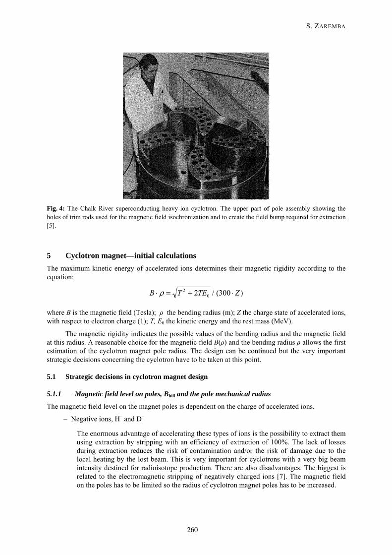
Fig. 4: The Chalk River superconducting heavy-ion cyclotron. The upper part of pole assembly showing the holes of trim rods used for the magnetic field isochronization and to create the field bump required for extraction [5].
5 Cyclotron magnet—initial calculations The maximum kinetic energy of accelerated ions determines their magnetic rigidity according to the equation:
)300(/2 02 ZTETB ⋅+=⋅ ρ
where B is the magnetic field (Tesla); ρ the bending radius (m); Z the charge state of accelerated ions, with respect to electron charge (1); T, E0 the kinetic energy and the rest mass (MeV).
The magnetic rigidity indicates the possible values of the bending radius and the magnetic field at this radius. A reasonable choice for the magnetic field B(ρ) and the bending radius ρ allows the first estimation of the cyclotron magnet pole radius. The design can be continued but the very important strategic decisions concerning the cyclotron have to be taken at this point.
5.1 Strategic decisions in cyclotron magnet design
5.1.1 Magnetic field level on poles, Bhill and the pole mechanical radius
The magnetic field level on the magnet poles is dependent on the charge of accelerated ions.
– Negative ions, H– and D–
The enormous advantage of accelerating these types of ions is the possibility to extract them using extraction by stripping with an efficiency of extraction of 100%. The lack of losses during extraction reduces the risk of contamination and/or the risk of damage due to the local heating by the lost beam. This is very important for cyclotrons with a very big beam intensity destined for radioisotope production. There are also disadvantages. The biggest is related to the electromagnetic stripping of negatively charged ions [7]. The magnetic field on the poles has to be limited so the radius of cyclotron magnet poles has to be increased.
S. ZAREMBA
260
– Fully stripped positive ions
The problems of electromagnetic stripping do not exist so the magnetic field can soar to the limits of superconducting magnet technology. Therefore the radius of cyclotron poles can be small and the cyclotron magnet cheaper. The disadvantage of this choice is associated with the extraction system based on electrostatic deflector(s) and one or more magnetic channels. Such an extraction system is much more complicated and expensive than the stripping extraction system. On the other hand the advantage of fully stripped positive ions is related to the vacuum level necessary in the cyclotron. Negatively charged ions are stripped on a rest gas during acceleration so higher vacuum is required to accelerate the negative ions than the fully stripped positive ions.
The comparison of TRIUMF cyclotron accelerating H– ions to 520 MeV having a magnet pole radius of 8.59 m and PSI cyclotron accelerating protons (H+) to 590 MeV for a magnet pole radius of 4.50 m [8] is the good example of consequences of the choice of accelerated ion charge on the cyclotron magnet pole radius, the decision taken during the cyclotron magnet design.
– Less important, not fully stripped positive ions
Such ions can be extracted by stripping or by electrostatic deflection. The second choice is more frequent. The magnetic field can be higher than in negative-ion cyclotrons.
5.1.2 Gap between cyclotron magnet poles, g
The axial (vertical) gap g between cyclotron magnet poles can be small or large. The analysis below is more important for classical room-temperature machines.
5.1.2.1 The small gap
The small gap between poles reduces the number of ampere-turns in cyclotron coils necessary to produce the required magnetic field. The level of the magnetic field can be higher, thus reducing the magnet pole radius. Also the orbits of accelerated ions can be closer to the outer edge of the pole. This may facilitate extraction and is the basis of successful self-extraction from cyclotrons [9, 10].
5.1.2.2 The large gap
The large gap between poles provides the large space to place the necessary elements of injection, extraction, RF system, and the diagnostic probes, without too much effort. Such a large gap between the poles can make vacuum pumping easier. In this case one may expect more problems to obtain the high values of the magnetic field.
The case of the superconducting cyclotron is simpler. The gap may be greater because the magnetic field produced by the coils adds a very important contribution to the total magnetic field. The magnetic field provided by the fully saturated iron will be about 2.1 T.
5.1.3 Valley gap and valley field, Bvalley
The analysis concerning this aspect of superconducting cyclotrons is identical to that given above. This subject is more important for room-temperature cyclotrons. The gap in the valley can not be considered alone, it should be considered in comparison with a gap between cyclotron poles. The different gaps between the poles and between the valleys produce the azimuthally varying magnetic field (AVF cyclotron) [4].
MAGNETS FOR CYCLOTRONS
261
5.1.3.1 Small gap in valleys
The small gap in magnet valleys diminishes the flutter [4] of the magnetic field. Lower flutter values mean lower values of the frequency of axial (vertical) betatron oscillations and the possible problems of axial beam losses. To increase the axial betatron oscillations frequency, one often needs to introduce the spiralization of magnet poles even for low-kinetic-energy cyclotrons.
5.1.3.2 Large gap in valleys
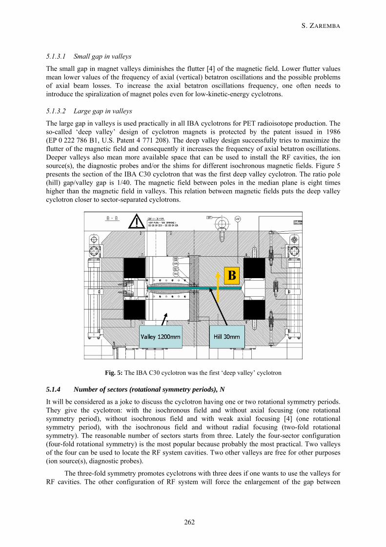
The large gap in valleys is used practically in all IBA cyclotrons for PET radioisotope production. The so-called ‘deep valley’ design of cyclotron magnets is protected by the patent issued in 1986 (EP 0 222 786 B1, U.S. Patent 4 771 208). The deep valley design successfully tries to maximize the flutter of the magnetic field and consequently it increases the frequency of axial betatron oscillations. Deeper valleys also mean more available space that can be used to install the RF cavities, the ion source(s), the diagnostic probes and/or the shims for different isochronous magnetic fields. Figure 5 presents the section of the IBA C30 cyclotron that was the first deep valley cyclotron. The ratio pole (hill) gap/valley gap is 1/40. The magnetic field between poles in the median plane is eight times higher than the magnetic field in valleys. This relation between magnetic fields puts the deep valley cyclotron closer to sector-separated cyclotrons.
Fig. 5: The IBA C30 cyclotron was the first ‘deep valley’ cyclotron
5.1.4 Number of sectors (rotational symmetry periods), N
It will be considered as a joke to discuss the cyclotron having one or two rotational symmetry periods. They give the cyclotron: with the isochronous field and without axial focusing (one rotational symmetry period), without isochronous field and with weak axial focusing [4] (one rotational symmetry period), with the isochronous field and without radial focusing (two-fold rotational symmetry). The reasonable number of sectors starts from three. Lately the four-sector configuration (four-fold rotational symmetry) is the most popular because probably the most practical. Two valleys of the four can be used to locate the RF system cavities. Two other valleys are free for other purposes (ion source(s), diagnostic probes).
The three-fold symmetry promotes cyclotrons with three dees if one wants to use the valleys for RF cavities. The other configuration of RF system will force the enlargement of the gap between
S. ZAREMBA
262
magnet poles. Such a three-fold configuration was frequently used in the first superconducting cyclotrons. The new projects of superconducting cyclotrons also propose four-fold symmetry magnets.
The very important radial resonance νr = N/2 can be reached for the higher energies of accelerated ions, taking into account that approximately νr = γ. This indicates that the greater number of rotational symmetry periods (6, 8,…) should be used and for practical reasons it is better to change the cyclotron magnet design from the compact to the sector-separated.
5.1.5 Median plane orientation: horizontal or vertical
The orientation of the cyclotron median plane is less important for cyclotron magnet designers but may be important for some end-users who want to install a new cyclotron in the existing vault of the previous machine.
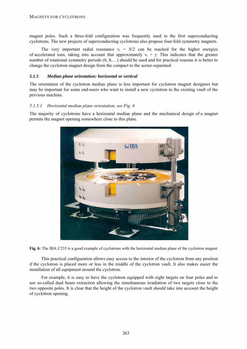
5.1.5.1 Horizontal median plane orientation, see Fig. 6
The majority of cyclotrons have a horizontal median plane and the mechanical design of a magnet permits the magnet opening somewhere close to this plane.
Fig. 6: The IBA C235 is a good example of cyclotrons with the horizontal median plane of the cyclotron magnet
This practical configuration allows easy access to the interior of the cyclotron from any position if the cyclotron is placed more or less in the middle of the cyclotron vault. It also makes easier the installation of all equipment around the cyclotron.
For example, it is easy to have the cyclotron equipped with eight targets on four poles and to use so-called dual beam extraction allowing the simultaneous irradiation of two targets close to the two opposite poles. It is clear that the height of the cyclotron vault should take into account the height of cyclotron opening.
MAGNETS FOR CYCLOTRONS
263
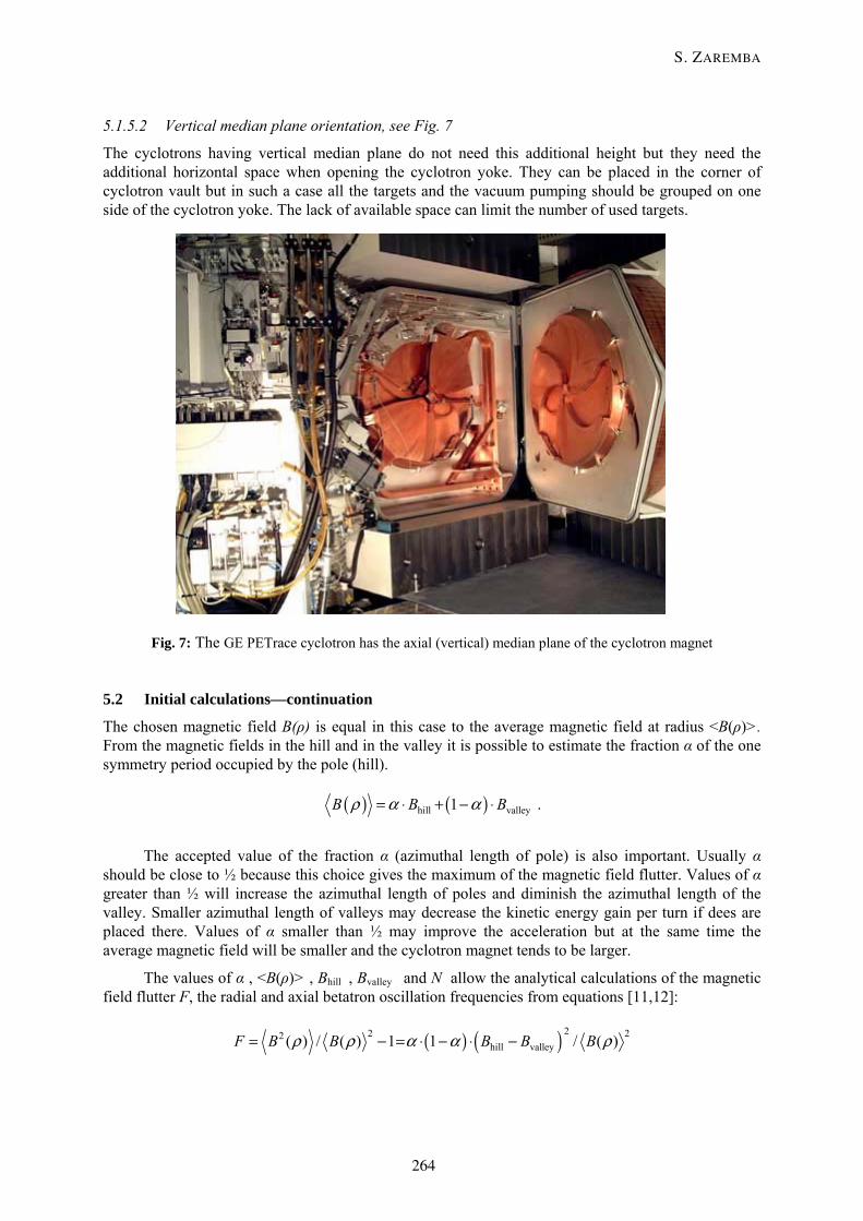
5.1.5.2 Vertical median plane orientation, see Fig. 7
The cyclotrons having vertical median plane do not need this additional height but they need the additional horizontal space when opening the cyclotron yoke. They can be placed in the corner of cyclotron vault but in such a case all the targets and the vacuum pumping should be grouped on one side of the cyclotron yoke. The lack of available space can limit the number of used targets.
Fig. 7: The GE PETrace cyclotron has the axial (vertical) median plane of the cyclotron magnet
5.2 Initial calculations—continuation
The chosen magnetic field B(ρ) is equal in this case to the average magnetic field at radius <B(ρ)>. From the magnetic fields in the hill and in the valley it is possible to estimate the fraction α of the one symmetry period occupied by the pole (hill).
( ) ( )hill valley1B B Bρ α α= ⋅ + − ⋅ .
The accepted value of the fraction α (azimuthal length of pole) is also important. Usually α should be close to ½ because this choice gives the maximum of the magnetic field flutter. Values of α greater than ½ will increase the azimuthal length of poles and diminish the azimuthal length of the valley. Smaller azimuthal length of valleys may decrease the kinetic energy gain per turn if dees are placed there. Values of α smaller than ½ may improve the acceleration but at the same time the average magnetic field will be smaller and the cyclotron magnet tends to be larger.
The values of α , <B(ρ)> , Bhill , Bvalley and N allow the analytical calculations of the magnetic field flutter F, the radial and axial betatron oscillation frequencies from equations [11,12]:
( ) ( ) 22 22hill valley( ) / ( ) 1 1 / ( )F B B B B Bρ ρ α α ρ= − = ⋅ − ⋅ −
S. ZAREMBA
264
( ) ( )2 2 2 2 2z 1 / 1 1 2 tanN N Fν γ ξ= − + − ⋅ ⋅ + ⋅
( )( ) ( )2 2 2 2 2 2r 3 / 1 4 1 2 tanN N N Fν γ ξ⎡ ⎤= + − − ⋅ ⋅ + ⋅⎣ ⎦
where ξ is the spiralization angle [4] defined as the angle between a tangent to spiral and the radius vector. The values of betatron oscillation frequencies have to be positive. It is necessary to change this simple model and to do all initial calculations again if the value of νz is negative or νr is smaller than 1 [4]. In addition, the reasonable minimum value νz can be estimated as 0.10–0.20 if one wants to keep a small gap between poles.
When all data are well-grounded and rational then the next step of initial estimations can be made. From ampere’s law one can estimate the number of ampere-turns nI of cyclotron coils necessary to generate the magnetic field.
( ) ( ) nILBgBldH =⋅⋅+⋅⋅=⋅∫ ironironiron0
hill0
11μμμ
where: μ0 , μiron are the relative magnetic permeability of vacuum and iron, g and Liron are the gap between poles and a length of the chosen path in the magnet iron. At this point it is difficult to determine the value of the magnetic permeability of iron μiron. This last formula can be simplified assuming that the magnetic permeability of iron is infinite and later the number of ampere-turns can be multiplied by a factor f significantly greater than 1, the overestimation of the factor f will only give greater coil dimensions or a greater coil current. If the cyclotron magnet is for a negative-ion machine then the magnetic field in the pole has to be low and only the return yoke of the cyclotron can have higher magnetic field (the factor f =1.2–1.3 probably will be OK). For the positive-ion, room-temperature cyclotron one will boost the magnetic field between poles and also the field in magnet poles so the multiplication factor should be greater (I would not hesitate to say 1.5–1.7).
The number of ampere-turns gives the estimation of cyclotron coil dimensions assuming a reasonable value of current density. The power P dissipated in each coil can be estimated assuming the cross-section of a copper tube used to produce coils. It is prudent to assume that the coils will be water-cooled. The simple formula below allows the estimation of a water-flow WF necessary to cool the coil and producing the moderate increase temperature of water ΔT between the entrance and the exit from the cooling circuit.
( ) ( ) ( )o C 60 kW / 4.19 / minT P WF l⎡ ⎤Δ = ⋅ ⋅⎣ ⎦ .
Only the estimation of a lateral return yoke dimensions is missing here but it may be quickly added assuming that the total magnetic flux Φ by surface S of poles and valleys is equal to the flux that has to pass by the return yoke.
hill allpoles valley allvalleysB S B SΦ = ⋅ + ⋅ .
The thickness of the return yoke can be estimated assuming that the iron of the return yoke is not completely saturated (e.g., 1.8 T) and the inner radius of the return yoke is determined by coil outer radius and a small clearance between.
All the estimations and the vision of the complete cyclotron should fit together. All these estimations usually take just a few hours and provide a good base for cyclotron magnet design using more sophisticated tools.
MAGNETS FOR CYCLOTRONS
265
6 Calculations of 2-D models Detailed two-dimensional magnet calculations have to first confirm the validity of the initial design. Then the weak points of the design should be corrected. Finally, the optimization of the cyclotron magnet and the whole cyclotron can be performed. All 2-D and 3-D calculations require the use of two-dimensional and three-dimensional computer codes. A non-exhaustive list of available programs is presented in Refs. [13,14].
There are two-dimensional computer codes that are available for free. POISSON-SUPERFISH group codes and their documentation are available from LAACG as described in Ref. [15].
It is worth using the two-dimensional codes independently from three-dimensional programs for several reasons. The most important are time and precision.
The two-dimensional models are much easier to create and so it takes no more than a few hours to build the valid model. Then the 2-D model debugging and the calculations of the solution assuming the non-linear magnetization B-H curve take just minutes. Only the optimization of two-dimensional models takes longer because of the number of created models. Some elements of the optimization can be done automatically but, as I know, the programs that perform such optimization are not free.
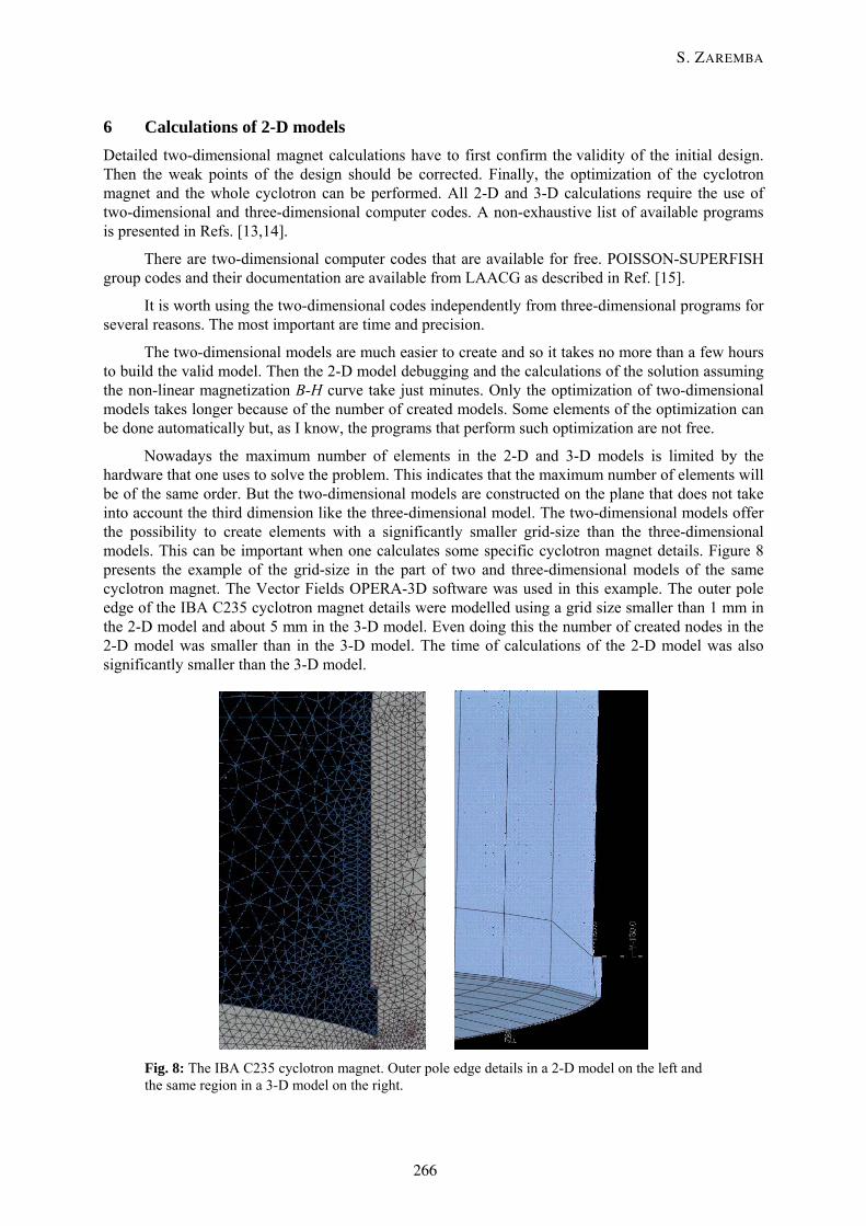
Nowadays the maximum number of elements in the 2-D and 3-D models is limited by the hardware that one uses to solve the problem. This indicates that the maximum number of elements will be of the same order. But the two-dimensional models are constructed on the plane that does not take into account the third dimension like the three-dimensional model. The two-dimensional models offer the possibility to create elements with a significantly smaller grid-size than the three-dimensional models. This can be important when one calculates some specific cyclotron magnet details. Figure 8 presents the example of the grid-size in the part of two and three-dimensional models of the same cyclotron magnet. The Vector Fields OPERA-3D software was used in this example. The outer pole edge of the IBA C235 cyclotron magnet details were modelled using a grid size smaller than 1 mm in the 2-D model and about 5 mm in the 3-D model. Even doing this the number of created nodes in the 2-D model was smaller than in the 3-D model. The time of calculations of the 2-D model was also significantly smaller than the 3-D model.
Fig. 8: The IBA C235 cyclotron magnet. Outer pole edge details in a 2-D model on the left and the same region in a 3-D model on the right.
S. ZAREMBA
266
The two-dimensional codes essentially solve the problems in which the third dimension is infinite or at least long enough to be considered as infinite. They also serve to solve the axially symmetric (cylindrical) three-dimensional problems. It is difficult to consider cyclotron magnets with the azimuthally varying magnetic field as the axially symmetric but this difficulty can be overcome by the method of stacking factors. The stacking factors can be used in the regions where the magnet structure significantly differs from the axially symmetric (sectors and valleys, important holes in the yoke). The stacking factor SF is defined as the fraction of the circle occupied by the real ferromagnetic material. This stacking factor SF modifies the magnetic properties of iron and replaces it by the iron-like material described by the modified B-H curve:
( )HBSFHB ⋅−⋅+⋅= 00pseudo μμ
where B and H are related by the curve of B-H for the real ferromagnetic material.
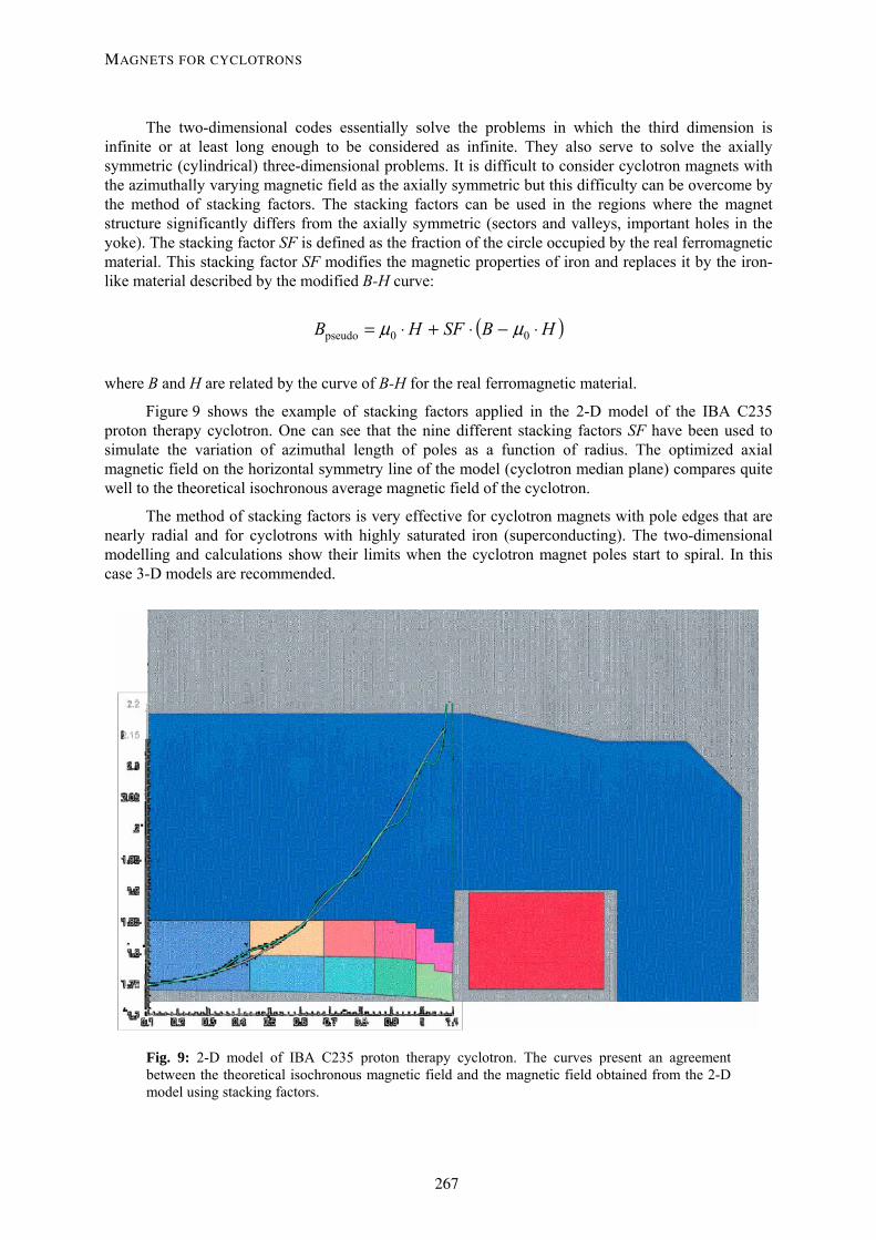
Figure 9 shows the example of stacking factors applied in the 2-D model of the IBA C235 proton therapy cyclotron. One can see that the nine different stacking factors SF have been used to simulate the variation of azimuthal length of poles as a function of radius. The optimized axial magnetic field on the horizontal symmetry line of the model (cyclotron median plane) compares quite well to the theoretical isochronous average magnetic field of the cyclotron.
The method of stacking factors is very effective for cyclotron magnets with pole edges that are nearly radial and for cyclotrons with highly saturated iron (superconducting). The two-dimensional modelling and calculations show their limits when the cyclotron magnet poles start to spiral. In this case 3-D models are recommended.
Fig. 9: 2-D model of IBA C235 proton therapy cyclotron. The curves present an agreement between the theoretical isochronous magnetic field and the magnetic field obtained from the 2-D model using stacking factors.
MAGNETS FOR CYCLOTRONS
267
7 Calculations of 3-D models The three-dimensional magnet calculations at first have to confirm the validity of the initial design and 2-D calculations. The constructed 3-D models should include as much detail as possible, specially focusing on the magnet features (spiralization of poles, complicated correction coils) that can not be correctly modelled using the previous methods. Then the weak points of the design should be corrected. Finally, the optimization of the cyclotron magnet and the whole cyclotron can be performed.
It is always worth diminishing the number of nodes in the 3-D model, which consequently reduces also the time of calculations. This can be done by the application of all possible symmetries of the cyclotron magnet. Some magnet details can also be neglected remembering that their influence on the magnetic field in the median plane is 0 (e.g., holes for screws on the outer side of the return yoke necessary for handling and to fix other cyclotron subsystem elements). Unfortunately the full model is always necessary when one wants to study the influence in the cyclotron median plane of different imperfections such as, for example, the shift and/or the rotation of the upper part with respect to the lower part of cyclotron, the shift and/or the rotation of one coil with respect to the median plane of the cyclotron, the mechanical errors of one or more poles etc.
The coil conductors created in the two-dimensional calculations are very simple and their magnetic field is calculated very quickly. Three-dimensional programs offer, except for the library of the standard shape conductors, practically unlimited possibilities for creating the shapes of conductors like the sequence of bricks with variable cross-section. The magnetic field of coils having very exotic shapes (e.g., particular trim-coils) can be calculated this way but usually it takes a long time.
The three-dimensional models are close to reality. Therefore the results of magnetic field measurements are expected to be close to the results of calculations. The IBA experience is that using OPERA-3D software from Vector Fields [17] one can expect a difference of 2–3 per cent between absolute calculated and measured values. These field differences can be explained by the numerical precision of the software, by the differences of the B-H curves, and some geometrical differences between the model and the real cyclotron magnet. The magnetic field differences become less than 0.5 per cent when comparing the magnetic fields for small changes of the magnet geometry (corrections of pole edges, shift of shims, different coil current).
The results of 3-D magnetic field calculations give maximum information about the magnetic field in any point of the model and around it. Very often they are used to create the magnetic field maps in the cyclotron magnet median plane or in the three dimensions around this plane. Such a magnetic field map becomes part of the input data to programs calculating the trajectories of particles and to the programs calculating properties of the magnetic field, for example the equilibrium orbit codes based on Ref. [12].
The most important part of output from the equilibrium orbit codes presents the values of the frequency error, the integrated phase shift of particles, and betatron frequencies. The magnet model has to be changed when one or more parameters are not acceptable. Our experience indicates also that during the creation of the 3-D cyclotron magnet model one should always foresee the possibilities of unexpected changes of the model geometry without having to construct the model from scratch once again. The fully acceptable values of the frequency error and of the integrated phase shift of particles ensure the isochronism of the magnetic field. The correct values of betatron frequencies confirm the focusing properties of the magnetic field and the absence of or a smooth passage by dangerous resonances during acceleration. A certain number of time-consuming iterations is usually necessary to optimize the cyclotron magnet and to obtain a fully acceptable cyclotron. IBA experience shows that this stage of the magnet design lasts much longer than the previous 2-D calculations.
Magnetic calculations are followed by calculations of the mechanical structure of the magnet.
S. ZAREMBA
268
8 A few words about mechanical design The analysis of mechanical deformations with a request for their minimum and the practical aspects of handling of the magnet pieces are the most important tasks of these calculations.
Mechanical calculations should take into account:
– weight of total magnet and/or weight of magnet pieces,
– magnetic forces between magnet elements,
– forces due to atmospheric pressure outside and the vacuum inside cyclotron,
– possibility to fix together all magnet elements and other cyclotron subsystems.
9 Conclusion Cyclotron magnet design and calculations should always consider interaction with the
– RF system,
– vacuum pumping,
– ion source or injection system,
– extraction system,
– diagnostic probes.
Acknowledgements I wish to thank my colleagues from the IBA R&D Department who helped me in the preparation of the lecture and this article for the CERN Accelerator School.
In the end and just for fun a short story for all readers who got to here. It was a few years ago. An English-speaking journalist spent one day at IBA writing an article about the company. He sent the article for correction before printing. We recommended the removal of the short paragraph and he did it. The title and the text are below. Evidently, he did not participate in CAS.
How the technology works The IBA cyclotron, a 2 metre wide washing-machine like vessel constructed of 15 cm thick iron walls, contains a vacuum chamber. A ‘target substance’ of gas, liquid or solid material is placed inside the vacuum chamber and then is bombarded with high energy (up to 30 million volts) RF waves (Radio frequency). This causes the nuclear particles (neutrons and deuterons) of the target to ‘accelerate’ inside the vacuum chamber. As the highly charged atomic particles spiral their way around the cyclotron, they are separated by a very powerful magnet called a ‘stripper’ which in effect ‘strips away’ individual particles to deliver radioactive isotopes.
References [1] H. Blosser, NSCL, East Lansing, MI, USA, private communication.
[2] J.J. Livingood, Principles of Cyclic Particle Accelerators (Van Nostrand, New York, 1961).
MAGNETS FOR CYCLOTRONS
269
[3] S. Humphries, Principles of Charged Particle Acceleration (Wiley, New York, 1986). Also Web page: http://www.fieldp.com/cpa/cpa.html.
[4] F. Chautard, Beam dynamics for cyclotrons; CERN Report of this CERN Accelerator School on Small Accelerators, Zeegse, the Netherlands, 24 May – 2 June 2005.
[5] J.H. Ormrod, C.B. Bigham et al., Status of the Chalk River Superconducting Heavy-Ion Cyclotron, Proceedings of the 9th International Conference on Cyclotrons and their Applications, 1981, Caen, France, p. 159–167.
[6] M. Schippers et al., Beam-dynamics studies in a 250 MeV superconducting cyclotron with a particle tracking program, Proceedings of the 33rd European Cyclotron Progress Meeting, 17–21 September 2002, Warsaw and Krakow, Poland, Nukleonika, 48, supplement 2, 2003, S145–S147.
[7] G.M. Stinson et al., Electric dissociation of H– ions by magnetic fields, Nucl. Instrum. Methods 74 (1969) 333–341.
[8] Cyclotrons and their Applications 2001, Proceedings of the Sixteenth International Conference, East Lansing, MI, USA, 2001, p. 489 and 527.
[9] W. Kleeven et al., The IBA self-extracting cyclotron project, Proceedings of the 33rd European Cyclotron Progress Meeting, 17–21 September 2002, Warsaw and Krakow, Poland, Nukleonika, 48, supplement 2, 2003, S59–S68.
[10] W. Kleeven, Injection and extraction, CERN Report of this CERN Accelerator School on Small Accelerators, Zeegse, the Netherlands, 24 May – 2 June 2005.
[11] H.L. Hagedoorn and N.F. Verster, Orbits in an AVF Cyclotron, Nucl. Instrum. and Methods 18, 19 (1962) 201–228.
[12] M.M. Gordon, Computation of closed orbits and basic focusing properties for sector-focused cyclotrons and the design of ‘CYCLOPS’; Part. Accel. 16 (1984), 39–62.
[13] G.G. Molinari, Existing commercial tools and criteria of selection, in Short Course Computer Aided Electromagnetic Analysis and Design: a Technical Introduction, Munich, November 1990.
[14] Computer Codes for Particle Accelerator Design and Analysis: A Compendium; LA-UR-90-1766, Los Alamos Accelerator Code Group, Second Edition, May 1990.
[15] F.L. Krawczyk et al., The Los Alamos Accelerator Code Group, AOT-1, MS H817, Los Alamos National Laboratory, Los Alamos, NM 87545 USA, http://epaper.kek.jp/p95/ARTICLES/MPB/MPB16.PDF.
[16] W. Beeckman, PE2D modelling of the Cyclone230 cyclotron; part of Cyclotron Design with PE2D and TOSCA softwares at IBA; Proceedings of VECTOR FIELDS European User Meeting, Ion Beam Applications, Louvain-la-Neuve, Belgium, September 1992.
[17] Vector Fields Ltd, 24 Bankside, Kidlington Oxford OX5 1JE, UK; see http://www.vectorfields.co.uk/ or http://www.vectorfields.com/.
S. ZAREMBA
270