magnetically coupled centrifugal pumps … · centrifugal pumps with complex mechanical shaft seals...
TRANSCRIPT
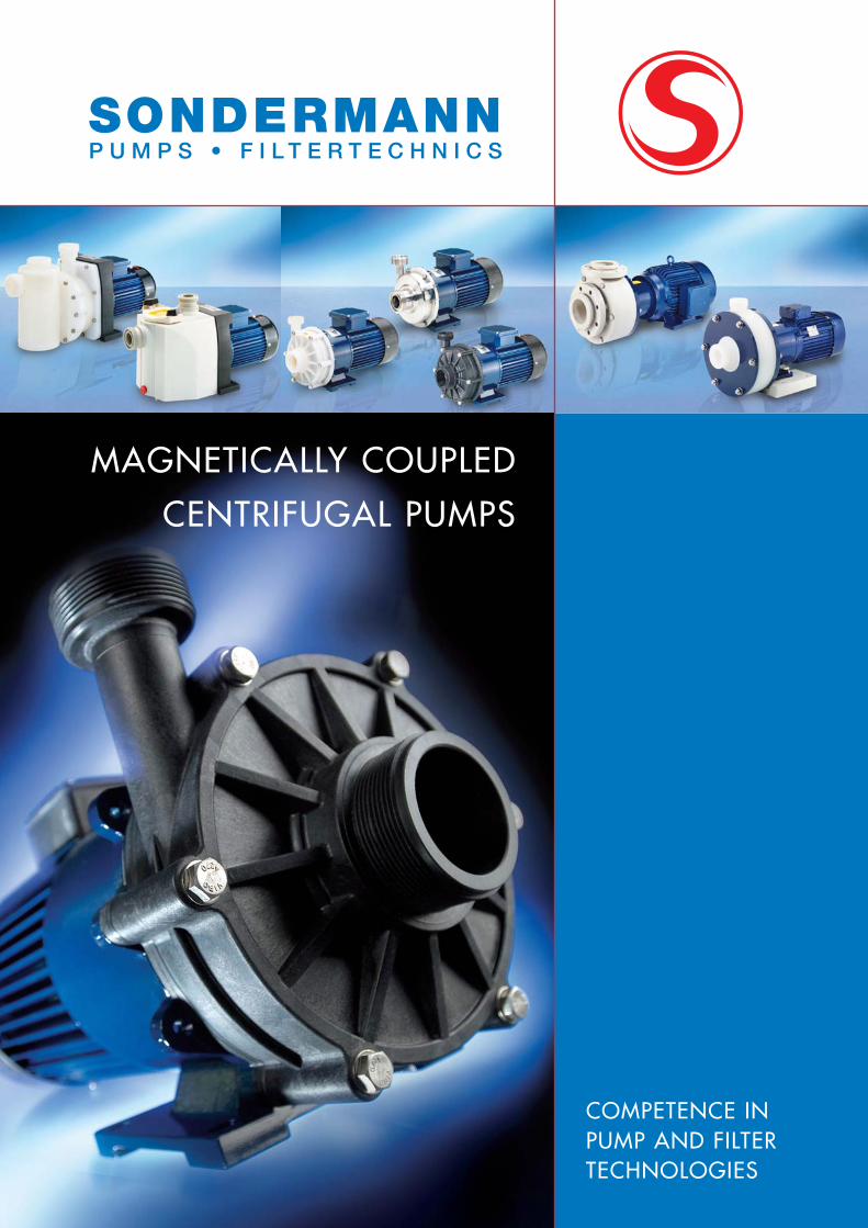
COMPETENCE IN PUMP AND FILTERTECHNOLOGIES
MAGNETICALLY COUPLED
CENTRIFUGAL PUMPS
Extremely safe products, extremely reliable service. This is our tradition. And this is why, for decades, experts have trusted in SONDERMANN products and devices. For many reasons such as …
… LONG-STANDING EXPERIENCE
As early as 1961, SONDERMANN supplied the first magneticallycoupled centrifugal pump. The technological superiority we hadat that time has been our outstanding feature up to this day. Our special pumps are used in trade and industry all over theworld. Many years of acquiring know-how also find expressionin the services rendered for the benefit of our clients. Actually,there should be no user problem we do not resolve. This, also, is a matter of experience.
... STRONG PARTNERS
Working now together with FLUX-Geräte GmbH, we are evenstronger than before. Our network of customer advisors hasexpanded and we are able to offer a wider range of problemsolutions. Whatever challenge of fluid delivery you face, the jobwill be done best by either a SONDERMANN or a FLUX pump.Just try us.
... EXCELLENT PRODUCT QUALITY
SONDERMANN is on the outside. Made in Germany is inside. All our pumps and filters are entirely manufactured in Germany.This is certainly one reason for the superior quality of our pro-ducts. Since we are very serious about each pump and filter,every single one is thoroughly checked in several stages before itleaves the company – with checks down the entire characteristiccurve. And of course in accordance with the ISO 9001 qualitystandard.
... RELIABLE SERVICE
You will recognize a genuine SONDERMANN pump by itsoperating reliability. And it operates at your location! To achieve this, we make every effort to help you in caseof need. In Germany only, especially trained advisors are available at 14 sales locations. From there we coordinateour service operations so that we arrive at your place asquick as possible.
... SPECIAL DESIGNS TO MEETINDIVIDUAL DEMANDS
Please do not hesitate to tell us your specific type of problem. It is a fact that standard designs often are notadequate for the use required. As a consequence, we are best prepared for special designs – and are able torealize them in no time. If we exactly know your problem,we will be able to find a way to resolve it. This is alsowhat SONDERMANN stands for.
2
SONDERMANN MAKES THE DIFFERENCE
SONDERMANN is a member in the association surface technology.
TABLE OF CONTENTS
3
Operating principle and constructional design of RM-type pumps 4 – 5
Modular design; Type designation code of RM pumps 6 – 7
Overview of non-self-priming pumps of the RM type 8 – 9
Overview of self-priming pumps of RMS and RMB types 10
RM pump of type RM-TS, safe to run dry 11
RM pump of type 1, non-self-priming 12 – 13
RM pump of type 1.5, non-self-priming 14 – 15
RM pump of type 2, non-self-priming 16 – 17
RM pump of type 2U, non-self-priming 18
RM pump of type 2D, non-self-priming 19
RM pump of type 3, non-self-priming 20 – 21
RM pump of type 4, non-self-priming 22 – 23
RM pump of type 4.5, non-self-priming 24 – 25
RM pump of type 5, non-self-priming 26 – 27
RMS pump of type 2.1, self-priming 28 – 29
RMB pump of type 3.1, self-priming 30 – 31
RM with priming tank/RM with frequency converter 32
Accessories 33
RM-Cool mini-pump 34 – 35
Pump protectors; Flow monitors 36 – 37
Sales representations in Germany and abroad 38 – 39
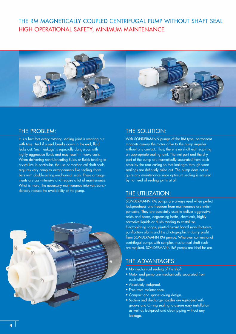
THE PROBLEM:It is a fact that every rotating sealing joint is wearing out with time. And if a seal breaks down in the end, fluidleaks out. Such leakage is especially dangerous withhighly aggressive fluids and may result in heavy costs. When delivering non-lubricating fluids or fluids tending tocrystallize in particular, the use of mechanical shaft sealsrequires very complex arrangements like sealing cham-bers with double-acting mechanical seals. These arrange-ments are cost-intensive and require a lot of maintenance.What is more, the necessary maintenance intervals consi-derably reduce the availability of the pump.
THE SOLUTION: With SONDERMANN pumps of the RM type, permanent magnets convey the motor drive to the pump impeller without any contact. Thus, there is no shaft exit requiringan appropriate sealing joint. The wet part and the drypart of the pump are hermetically separated from eachother by the rear casing so that leakages through wornsealings are definitely ruled out. The pump does not re -quire any maintenance since optimum sealing is ensuredby no need of sealing joints at all.
THE UTILIZATION:SONDERMANN RM pumps are always used when perfectleakproofness and freedom from maintenance are indis-pensable. They are especially used to deliver aggressiveacids and bases, degreasing baths, chemicals, highly corrosive liquids or fluids tending to cristallize. Electroplating shops, printed-circuit board manufacturers,purification plants and the photographic industry profitfrom SONDERMANN RM pumps. Wherever conventionalcentrifugal pumps with complex mechanical shaft sealsare required, SONDERMANN RM pumps are ideal for use.
THE ADVANTAGES:• No mechanical sealing of the shaft.• Motor and pump are mechanically separated from
each other.• Absolutely leakproof.• Free from maintenance.• Compact and space-saving design.• Suction and discharge nozzles are equipped with
groove and O-ring sealing to assure easy installationas well as leakproof and clean piping without any leakage.
4
THE RM MAGNETICALLY COUPLED CENTRIFUGAL PUMP WITHOUT SHAFT SEALHIGH OPERATIONAL SAFETY, MINIMUM MAINTENANCE
5
OPERATING PRINCIPLE
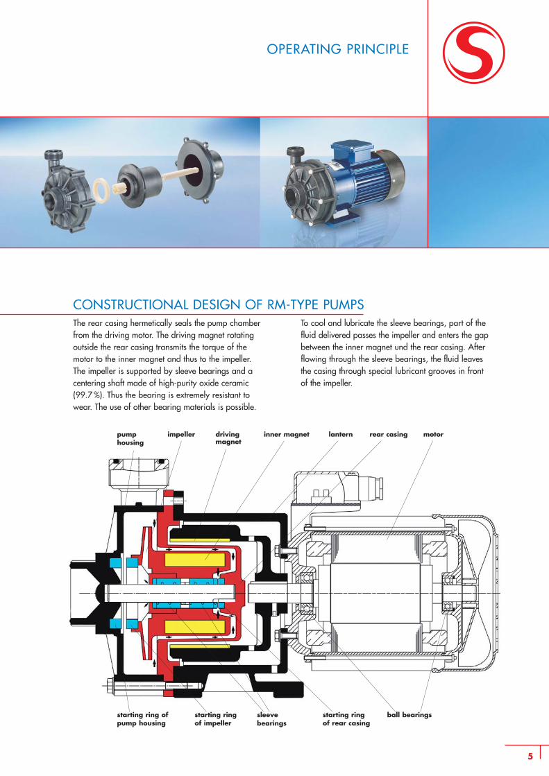
CONSTRUCTIONAL DESIGN OF RM-TYPE PUMPSThe rear casing hermetically seals the pump chamber from the driving motor. The driving magnet rotating outside the rear casing transmits the torque of the motor to the inner magnet and thus to the impeller. The impeller is supported by sleeve bearings and a centering shaft made of high-purity oxide ceramic (99.7 %). Thus the bearing is extremely resistant to wear. The use of other bearing materials is possible.
To cool and lubricate the sleeve bearings, part of thefluid delivered passes the impeller and enters the gapbetween the inner magnet und the rear casing. After flowing through the sleeve bearings, the fluid leaves the casing through special lubricant grooves in front of the impeller.
pump housing
impeller driving magnet
inner magnet lantern rear casing motor
starting ring ofpump housing
starting ringof impeller
sleevebearings
starting ringof rear casing
ball bearings
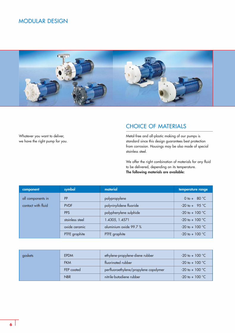
Whatever you want to deliver, we have the right pump for you.
6
MODULAR DESIGN
CHOICE OF MATERIALS
Metal-free and all-plastic making of our pumps isstandard since this design guarantees best protectionfrom corrosion. Housings may be also made of specialstainless steel.
We offer the right combination of materials for any fluidto be delivered, depending on its temperature.The following materials are available:
component symbol material temperature range
all components in PP polypropylene 0 to + 80 °C
contact with fluid PVDF polyvinylidene fluoride -20 to + 95 °C
PPS polyphenylene sulphide -20 to + 100 °C
stainless steel 1.4305, 1.4571 -20 to + 100 °C
oxide ceramic aluminium oxide 99.7 % -20 to + 100 °C
PTFE graphite PTFE graphite -20 to + 100 °C
gaskets EPDM ethylene-propylene-diene rubber -20 to + 100 °C
FKM fluorinated rubber -20 to + 100 °C
FEP coated perfluoroethylene/propylene copolymer -20 to + 100 °C
NBR nitrile-butadiene rubber -20 to + 100 °C
7
THE CHARACTERISTICS OF RM PUMPS
DESIGNATION CODE OF RM PUMPS
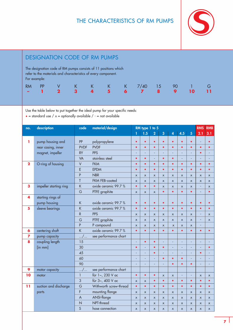
The designation code of RM pumps consists of 11 positions which refer to the materials and characteristics of every component.For example:
RM PP V K K K K 7/40 15 90 1 G– 1 2 3 4 5 6 7 8 9 10 11
Use the table below to put together the ideal pump for your specific needs:
• = standard use / x = optionally available / - = not available
RMS RMBno. description code material/design RM type 1 to 51 1.5 2 3 4 4.5 5 2.1 3.1
1 pump housing and PP polypropylene • • • • • • • - •rear casing, inner PVDF PVDF • • • • • • • • •magnet, impeller RY PPS - - - - - - - • -
VA stainless steel • • - • • - - - -2 O-ring of housing V FKM • • • • • • • • •
E EPDM • • • • • • • • •P NBR x x x x x x x x xT FKM FEB-coated x x x x x x x x x
3 impeller starting ring K oxide ceramic 99.7 % • • • x x x x - xG PTFE graphite x x x • • • • - •
4 starting rings ofpump housing K oxide ceramic 99.7 % • • • • • • • • •
5 sleeve bearings K oxide ceramic 99.7 % • • • • • • • • •R PPS x x x x x x x - x
G PTFE graphite x x x x x x x - xP P compound x x x x x x x -
6 centering shaft K oxide ceramic 99.7 % • • • • • • • • •7 pump capacity .../... see performance chart8 coupling length 15 - • • - - - - - -
[in mm] 30 • - • • - - - - •45 - - • - - - - • -60 - - - • • • - - -90 - - - - • • • - -
9 motor capacity .../... see performance chart10 motor 1 für 1~, 230 V ac • • • x x - - x x
3 für 3~, 400 V ac x x • • • • • • •11 suction and discharge G Withworth screw-thread • • • • • • • • •
parts F mounting flange x x x x x x x x xA ANSI-flange x x x x x x x x xN NPT-thread x x x x x x x x xS hose connection x x x x x x x x x
8
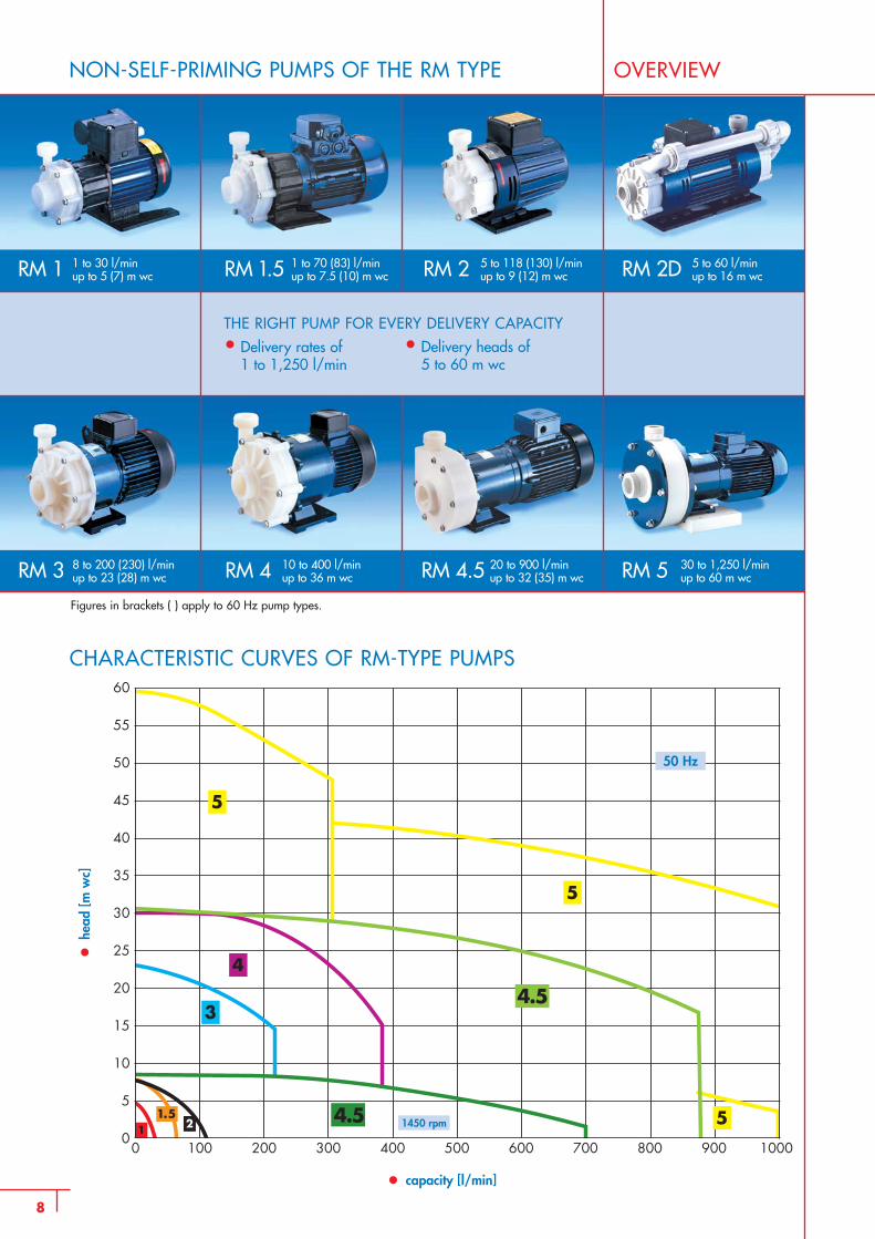
NON-SELF-PRIMING PUMPS OF THE RM TYPE OVERVIEW
RM 1 RM 1.5
THE RIGHT PUMP FOR EVERY DELIVERY CAPACITY
• Delivery rates of1 to 1,250 l/min
30 to 1,250 l/minup to 60 m wc
1 to 30 l/minup to 5 (7) m wc
1 to 70 (83) l/minup to 7.5 (10) m wc
5 to 118 (130) l/minup to 9 (12) m wc
5 to 60 l/minup to 16 m wc
8 to 200 (230) l/minup to 23 (28) m wc
10 to 400 l/minup to 36 m wc
CHARACTERISTIC CURVES OF RM-TYPE PUMPS
•he
ad [m
wc]
• capacity [l/min]
50 Hz
1450 rpm
20 to 900 l/minup to 32 (35) m wc
RM 2 RM 2D
RM 3 RM 4 RM 4.5 RM 5
• Delivery heads of5 to 60 m wc
Figures in brackets ( ) apply to 60 Hz pump types.
9
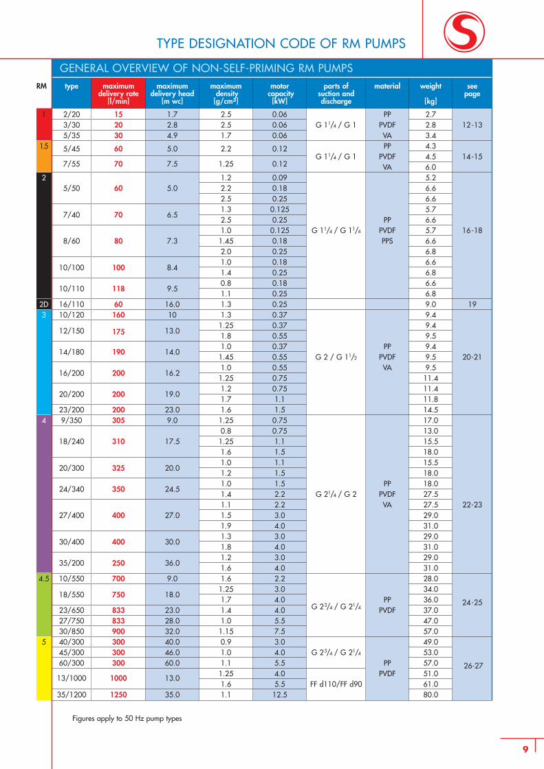
TYPE DESIGNATION CODE OF RM PUMPS
GENERAL OVERVIEW OF NON-SELF-PRIMING RM PUMPSparts of
suction anddischarge
G 11/4 / G 1
G 11/4 / G 1
G 11/4 / G 11/4
G 2 / G 11/2
G 21/4 / G 2
G 23/4 / G 21/4
G 23/4 / G 21/4
FF d110/FF d90
material
PPPVDFVAPP
PVDFVA
PPPVDFPPS
PPPVDFVA
PPPVDFVA
PPPVDF
PPPVDF
weight
[kg]
2.72.83.44.34.56.05.26.66.65.76.65.76.66.86.66.86.66.89.09.49.49.59.49.59.511.411.411.814.517.013.015.518.015.518.018.027.527.529.031.029.031.029.031.028.034.036.037.047.057.049.053.057.051.061.080.0
seepage
12-13
14-15
16-18
19
20-21
22-23
24-25
26-27
motorcapacity
[kW]
0.060.06 0.06
0.12
0.12
0.090.180.250.1250.250.1250.180.250.180.250.180.250.250.370.370.550.370.550.550.750.751.11.50.750.751.11.51.11.51.52.22.23.04.03.04.03.04.02.23.04.04.05.57.53.04.05.54.05.512.5
type
2/203/305/35
5/45
7/55
5/50
7/40
8/60
10/100
10/110
16/11010/120
12/150
14/180
16/200
20/200
23/2009/350
18/240
20/300
24/340
27/400
30/400
35/200
10/550
18/550
23/65027/75030/85040/30045/30060/300
13/1000
35/1200
maximumdelivery head
[m wc]
1.72.84.9
5.0
7.5
5.0
6.5
7.3
8.4
9.5
16.010
13.0
14.0
16.2
19.0
23.09.0
17.5
20.0
24.5
27.0
30.0
36.0
9.0
18.0
23.028.032.040.046.060.0
13.0
35.0
maximumdelivery rate
[l/min]
152030
60
70
60
70
80
100
118
60160
175
190
200
200
200305
310
325
350
400
400
250
700
750
833833900300300300
1000
1250
maximumdensity
[g/cm3]
2.52.51.7
2.2
1.25
1.22.22.51.32.51.01.452.01.01.40.81.11.31.31.251.81.01.451.01.251.21.71.61.250.81.251.61.01.21.01.41.11.51.91.31.81.21.61.61.251.71.41.01.150.91.01.11.251.61.1
RM
1
1.5
2
2D3
4
4.5
5
Figures apply to 50 Hz pump types
RM type maximum maximum maximum motor material weight parts of seedelivery rate delivery head/ density capacity [kg] suction and page
[l/min] suction head [g/cm3] [kW] discharge[m wc]
RMS 7 10/11.55 0.37
PVDF8.5
2.0 0.55 9.09/8
7 12/31.55 0.37
PPS8.5
2.0 0.55 9.0 G 1/2 28-29
15 31/11.55 0.37
PVDF7.5 internal
2.0 0.55 8.0 thread34/1716.2 38/7
1.55 0.37PPS
7.52.0 0.55 8.0
RMB 12/175 175 12/31.0 0.55 10.01.4 0.75 PP 13.0 G 2 30-31
15/225 225 17/3.5 1.0 0.75 PVDF 13.0 external
18/250 240 18/1.0 1.2 0.75 13.0 thread
10
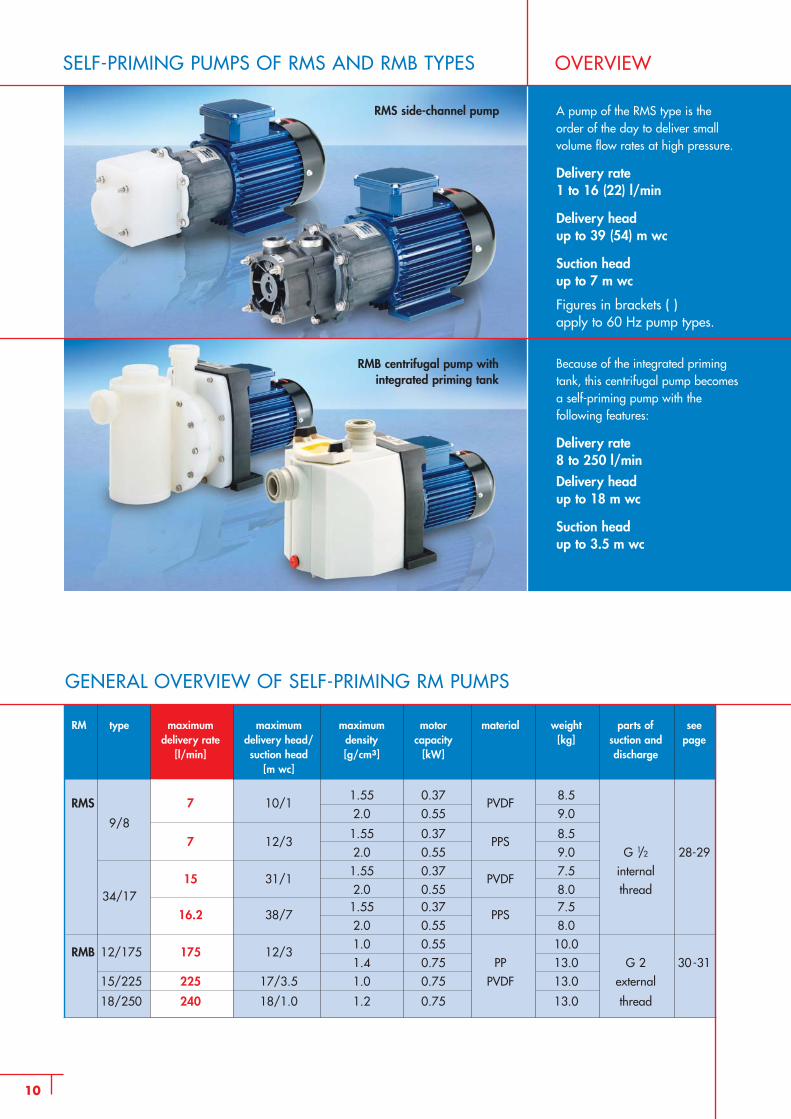
GENERAL OVERVIEW OF SELF-PRIMING RM PUMPS
SELF-PRIMING PUMPS OF RMS AND RMB TYPES OVERVIEW
RMS side-channel pump
Because of the integrated primingtank, this centrifugal pump becomesa self-priming pump with the following features:
Delivery rate 8 to 250 l/min
Delivery head up to 18 m wc
Suction head up to 3.5 m wc
A pump of the RMS type is the order of the day to deliver smallvolume flow rates at high pressure.
Delivery rate 1 to 16 (22) l/min
Delivery head up to 39 (54) m wc
Suction head up to 7 m wc
Figures in brackets ( ) apply to 60 Hz pump types.
RMB centrifugal pump with integrated priming tank
11
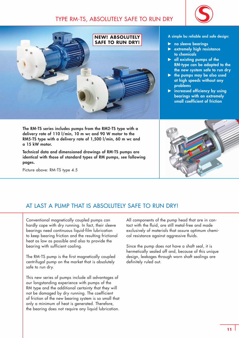
AT LAST A PUMP THAT IS ABSOLUTELY SAFE TO RUN DRY!
TYPE RM-TS, ABSOLUTELY SAFE TO RUN DRY
The RM-TS series includes pumps from the RM2-TS type with a delivery rate of 110 l/min, 10 m wc and 90 W motor to the RM5-TS type with a delivery rate of 1,500 l/min, 60 m wc and a 15 kW motor.
Technical data and dimensioned drawings of RM-TS pumps are identical with those of standard types of RM pumps, see followingpages.
Picture above: RM-TS type 4.5
A simple bu reliable and safe design:
� no sleeve bearings� extremely high resistance
to chemicals� all existing pumps of the
RM-type can be adapted to thethe new system safe to run dry
� the pumps may be also used at high speeds without any problems
� increased efficiency by using bearings with an extremely small coefficient of friction
NEW! ABSOLUTELYSAFE TO RUN DRY!
Conventional magnetically coupled pumps canhardly cope with dry running. In fact, their sleevebearings need continuous liquid-film lubrication to keep bearing friction and the resulting frictionalheat as low as possible and also to provide thebearing with sufficient cooling.
The RM-TS pump is the first magnetically coupledcentrifugal pump on the market that is absolutelysafe to run dry.
This new series of pumps include all advantages ofour longstanding experience with pumps of the RM type and the additional certainty that they willnot be damaged by dry running. The coefficient of friction of the new bearing system is so small thatonly a minimum of heat is generated. Therefore,the bearing does not require any liquid lubrication.
All components of the pump head that are in con-tact with the fluid, are still metal-free and madeexclusively of materials that assure optimum chemi-cal resistance against aggressive fluids.
Since the pump does not have a shaft seal, it ishermetically sealed off and, because of this uniquedesign, leakages through worn shaft sealings aredefinitely ruled out.
12
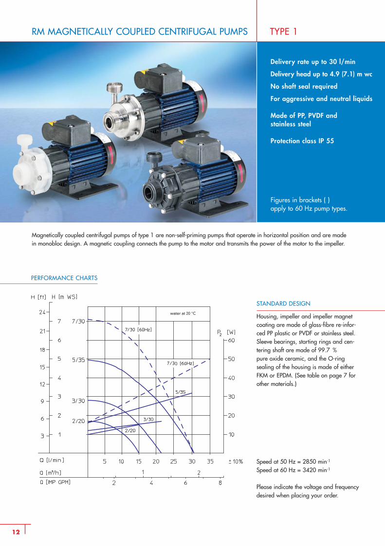
RM MAGNETICALLY COUPLED CENTRIFUGAL PUMPS
Magnetically coupled centrifugal pumps of type 1 are non-self-priming pumps that operate in horizontal position and are made in monobloc design. A magnetic coupling connects the pump to the motor and transmits the power of the motor to the impeller.
TYPE 1
Delivery rate up to 30 l/min
Delivery head up to 4.9 (7.1) m wc
No shaft seal required
For aggressive and neutral liquids
Made of PP, PVDF and stainless steel
Protection class IP 55
Figures in brackets ( ) apply to 60 Hz pump types.
PERFORMANCE CHARTS
STANDARD DESIGN
Housing, impeller and impeller magnetcoating are made of glass-fibre re-infor-ced PP plastic or PVDF or stainless steel.Sleeve bearings, starting rings and cen-tering shaft are made of 99.7 % pure oxide ceramic, and the O-ring sealing of the housing is made of eitherFKM or EPDM. (See table on page 7 forother materials.)
Speed at 50 Hz = 2850 min-1
Speed at 60 Hz = 3420 min-1
Please indicate the voltage and frequencydesired when placing your order.
water at 20 °C
13
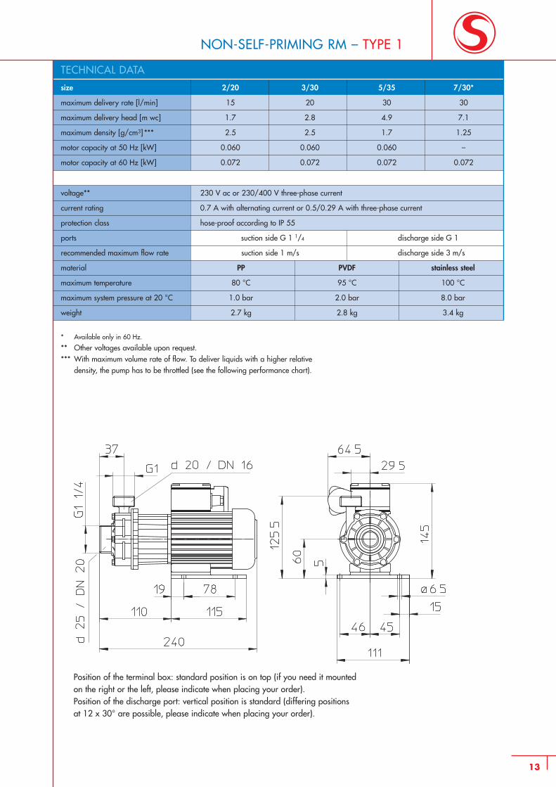
NON-SELF-PRIMING RM – TYPE 1
size 2/20 3/30 5/35 7/30*
maximum delivery rate [l/min] 15 20 30 30
maximum delivery head [m wc] 1.7 2.8 4.9 7.1
maximum density [g/cm3] *** 2.5 2.5 1.7 1.25
motor capacity at 50 Hz [kW] 0.060 0.060 0.060 –
motor capacity at 60 Hz [kW] 0.072 0.072 0.072 0.072
voltage** 230 V ac or 230/400 V three-phase current
current rating 0.7 A with alternating current or 0.5/0.29 A with three-phase current
protection class hose-proof according to IP 55
ports suction side G 1 1/4 discharge side G 1
recommended maximum flow rate suction side 1 m/s discharge side 3 m/s
material PP PVDF stainless steel
maximum temperature 80 °C 95 °C 100 °C
maximum system pressure at 20 °C 1.0 bar 2.0 bar 8.0 bar
weight 2.7 kg 2.8 kg 3.4 kg
* Available only in 60 Hz.
** Other voltages available upon request.*** With maximum volume rate of flow. To deliver liquids with a higher relative
density, the pump has to be throttled (see the following performance chart).
Position of the terminal box: standard position is on top (if you need it mounted on the right or the left, please indicate when placing your order).Position of the discharge port: vertical position is standard (differing positions at 12 x 30° are possible, please indicate when placing your order).
TECHNICAL DATA
14
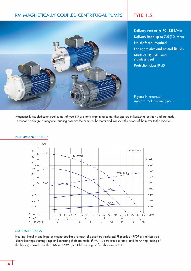
RM MAGNETICALLY COUPLED CENTRIFUGAL PUMPS TYPE 1.5
PERFORMANCE CHARTS
STANDARD DESIGN
Housing, impeller and impeller magnet coating are made of glass-fibre reinforced PP plastic or PVDF or stainless steel.Sleeve bearings, starting rings and centering shaft are made of 99.7 % pure oxide ceramic, and the O-ring sealing ofthe housing is made of either FKM or EPDM. (See table on page 7 for other materials.)
Delivery rate up to 70 (83) l/min
Delivery head up to 7.5 (10) m wc
No shaft seal required
For aggressive and neutral liquids
Made of PP, PVDF andstainless steel
Protection class IP 55
Figures in brackets ( ) apply to 60 Hz pump types.
Magnetically coupled centrifugal pumps of type 1.5 are non-self-priming pumps that operate in horizontal position and are madein monobloc design. A magnetic coupling connects the pump to the motor and transmits the power of the motor to the impeller.
water at 20 °C
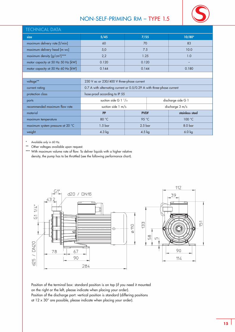
size 5/45 7/55 10/80*
maximum delivery rate [l/min] 60 70 83
maximum delivery head [m wc] 5,0 7.5 10.0
maximum density [g/cm3] *** 2,2 1.25 1.0
motor capacity at 50 Hz 50 Hz [kW] 0.120 0.120 –
motor capacity at 50 Hz 60 Hz [kW] 0.144 0.144 0.180
voltage** 230 V ac or 230/400 V three-phase current
current rating 0.7 A with alternating current or 0.5/0.29 A with three-phase current
protection class hose-proof according to IP 55
ports suction side G 1 1/4 discharge side G 1
recommended maximum flow rate suction side 1 m/s discharge 3 m/s
material PP PVDF stainless steel
maximum temperature 80 °C 95 °C 100 °C
maximum system pressure at 20 °C 1.5 bar 2.5 bar 8.0 bar
weight 4.3 kg 4.5 kg 6.0 kg
TECHNICAL DATA
15
NON-SELF-PRIMING RM – TYPE 1.5
* Available only in 60 Hz.
** Other voltages available upon request.*** With maximum volume rate of flow. To deliver liquids with a higher relative
density, the pump has to be throttled (see the following performance chart).
Position of the terminal box: standard position is on top (if you need it mounted on the right or the left, please indicate when placing your order).Position of the discharge port: vertical position is standard (differing positions at 12 x 30° are possible, please indicate when placing your order).
16
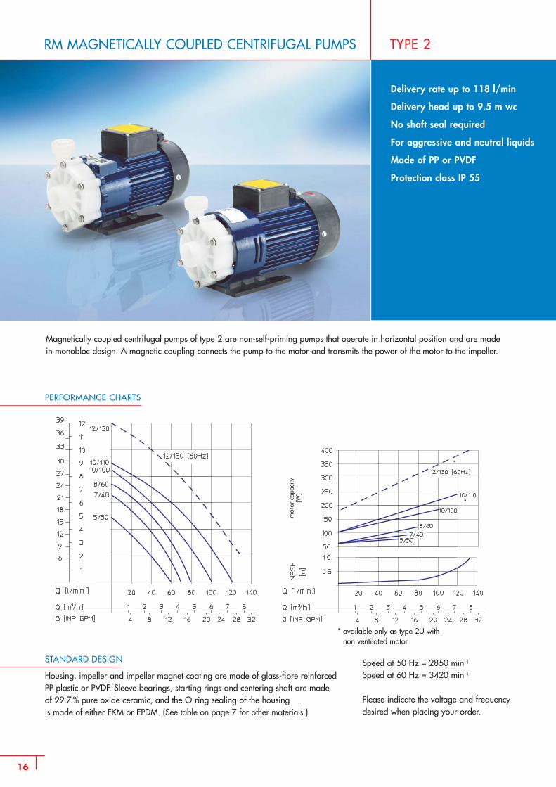
RM MAGNETICALLY COUPLED CENTRIFUGAL PUMPS
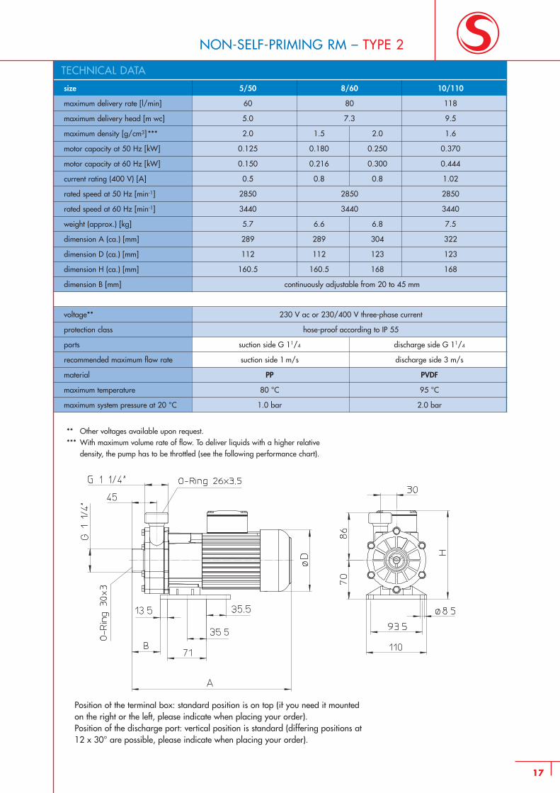
Magnetically coupled centrifugal pumps of type 2 are non-self-priming pumps that operate in horizontal position and are madein monobloc design. A magnetic coupling connects the pump to the motor and transmits the power of the motor to the impeller.
TYPE 2
Delivery rate up to 118 l/min
Delivery head up to 9.5 m wc
No shaft seal required
For aggressive and neutral liquids
Made of PP or PVDF
Protection class IP 55
PERFORMANCE CHARTS
STANDARD DESIGN
Housing, impeller and impeller magnet coating are made of glass-fibre reinforcedPP plastic or PVDF. Sleeve bearings, starting rings and centering shaft are made of 99.7 % pure oxide ceramic, and the O-ring sealing of the housing is made of either FKM or EPDM. (See table on page 7 for other materials.)
Speed at 50 Hz = 2850 min-1
Speed at 60 Hz = 3420 min-1
Please indicate the voltage and frequency desired when placing your order.
* available only as type 2U with non ventilated motor
*
*
*
mo
tor
cap
acity
[W]
TECHNICAL DATA
17
NON-SELF-PRIMING RM – TYPE 2
** Other voltages available upon request.*** With maximum volume rate of flow. To deliver liquids with a higher relative
density, the pump has to be throttled (see the following performance chart).
Position of the terminal box: standard position is on top (if you need it mounted on the right or the left, please indicate when placing your order).Position of the discharge port: vertical position is standard (differing positions at 12 x 30° are possible, please indicate when placing your order).
size 5/50 8/60 10/110
maximum delivery rate [l/min] 60 80 118
maximum delivery head [m wc] 5.0 7.3 9.5
maximum density [g/cm3] *** 2.0 1.5 2.0 1.6
motor capacity at 50 Hz [kW] 0.125 0.180 0.250 0.370
motor capacity at 60 Hz [kW] 0.150 0.216 0.300 0.444
current rating (400 V) [A] 0.5 0.8 0.8 1.02
rated speed at 50 Hz [min-1] 2850 2850 2850
rated speed at 60 Hz [min-1] 3440 3440 3440
weight (approx.) [kg] 5.7 6.6 6.8 7.5
dimension A (ca.) [mm] 289 289 304 322
dimension D (ca.) [mm] 112 112 123 123
dimension H (ca.) [mm] 160.5 160.5 168 168
dimension B [mm] continuously adjustable from 20 to 45 mm
voltage** 230 V ac or 230/400 V three-phase current
protection class hose-proof according to IP 55
ports suction side G 11/4 discharge side G 11/4
recommended maximum flow rate suction side 1 m/s discharge side 3 m/s
material PP PVDF
maximum temperature 80 °C 95 °C
maximum system pressure at 20 °C 1.0 bar 2.0 bar
continuously adjustable from 20 to 45 mm
18
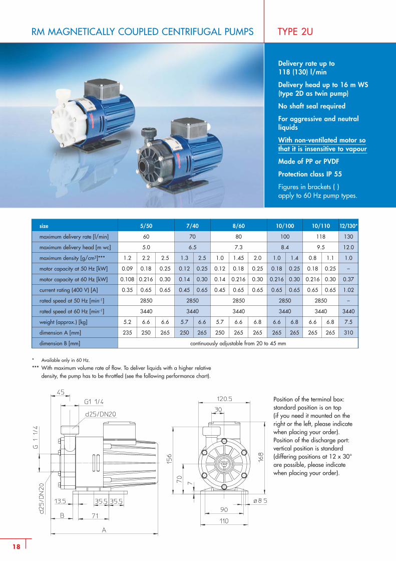
RM MAGNETICALLY COUPLED CENTRIFUGAL PUMPS TYPE 2U
Delivery rate up to118 (130) l/min
Delivery head up to 16 m WS (type 2D as twin pump)
No shaft seal required
For aggressive and neutral liquids
With non-ventilated motor sothat it is insensitive to vapour
Made of PP or PVDF
Protection class IP 55
Figures in brackets ( ) apply to 60 Hz pump types.
5/50
60
5.0
1.2 2.2 2.5
0.09 0.18 0.25
0.108 0.216 0.30
0.35 0.65 0.65
2850
3440
5.2 6.6 6.6
235 250 265
size
maximum delivery rate [l/min]
maximum delivery head [m wc]
maximum density [g/cm3]***
motor capacity at 50 Hz [kW]
motor capacity at 60 Hz [kW]
current rating (400 V) [A]
rated speed at 50 Hz [min-1]
rated speed at 60 Hz [min-1]
weight (approx.) [kg]
dimension A [mm]
dimension B [mm]
8/60
80
7.3
1.0 1.45 2.0
0.12 0.18 0.25
0.14 0.216 0.30
0.45 0.65 0.65
2850
3440
5.7 6.6 6.8
250 265 265
7/40
70
6.5
1.3 2.5
0.12 0.25
0.14 0.30
0.45 0.65
2850
3440
5.7 6.6
250 265
10/100
100
8.4
1.0 1.4
0.18 0.25
0.216 0.30
0.65 0.65
2850
3440
6.6 6.8
265 265
10/110
118
9.5
0.8 1.1
0.18 0.25
0.216 0.30
0.65 0.65
2850
3440
6.6 6.8
265 265
12/130*
130
12.0
1.0
–
0.37
1.02
–
3440
7.5
310
* Available only in 60 Hz.
*** With maximum volume rate of flow. To deliver liquids with a higher relative density, the pump has to be throttled (see the following performance chart).
Position of the terminal box:standard position is on top (if you need it mounted on theright or the left, please indicatewhen placing your order).Position of the discharge port:vertical position is standard (differing positions at 12 x 30°are possible, please indicatewhen placing your order).
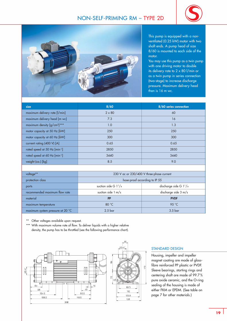
This pump is equipped with a non-ventilated (0.25 kW) motor with twoshaft ends. A pump head of size 8/60 is mounted to each side of themotor. You may use this pump as a twin pumpwith one driving motor to double its delivery rate to 2 x 80 l/min or as a twin pump in series connec tion(two-stage) to increase discharge pressure. Maximum delivery head then is 16 m wc.
8/60
2 x 80
7.3
1.0
250
300
0.65
2850
3440
8.5
size
maximum delivery rate [l/min]
maximum delivery head [m wc]
maximum density [g/cm3] ***
motor capacity at 50 Hz [kW]
motor capacity at 60 Hz [kW]
current rating (400 V) [A]
rated speed at 50 Hz [min-1]
rated speed at 60 Hz [min-1]
weight (ca.) [kg]
** Other voltages available upon request.*** With maximum volume rate of flow. To deliver liquids with a higher relative
density, the pump has to be throttled (see the following performance chart).
voltage** 230 V ac or 230/400 V three-phase current
protection class hose-proof according to IP 55
ports suction side G 11/4 discharge side G 11/4
recommended maximum flow rate suction side 1 m/s discharge side 3 m/s
material PP PVDF
maximum temperature 80 °C 95 °C
maximum system pressure at 20 °C 2.5 bar 3.5 bar
8/60 series connection
60
16
1.3
250
300
0.65
2850
3440
9.0
19
NON-SELF-PRIMING RM – TYPE 2D
STANDARD DESIGN
Housing, impeller and impeller magnet coating are made of glass-fibre reinforced PP plastic or PVDF.Sleeve bearings, starting rings andcentering shaft are made of 99.7 %pure oxide ceramic, and the O-ringsealing of the housing is made of either FKM or EPDM. (See table onpage 7 for other materials.)
20
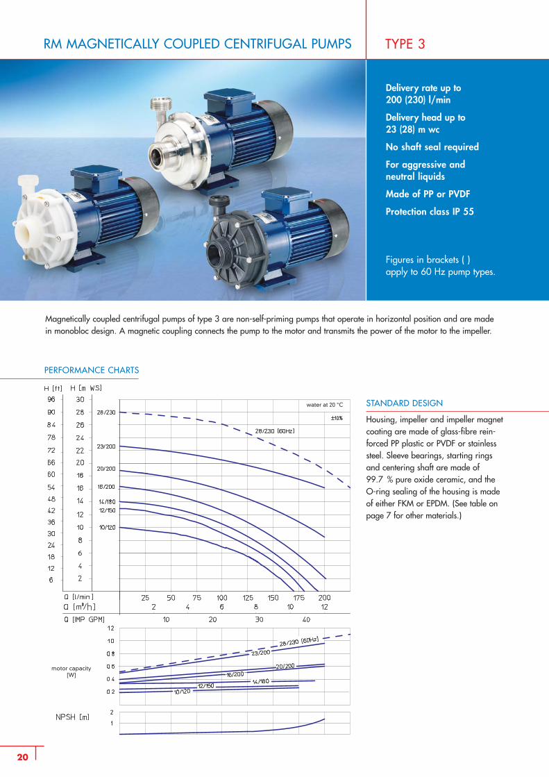
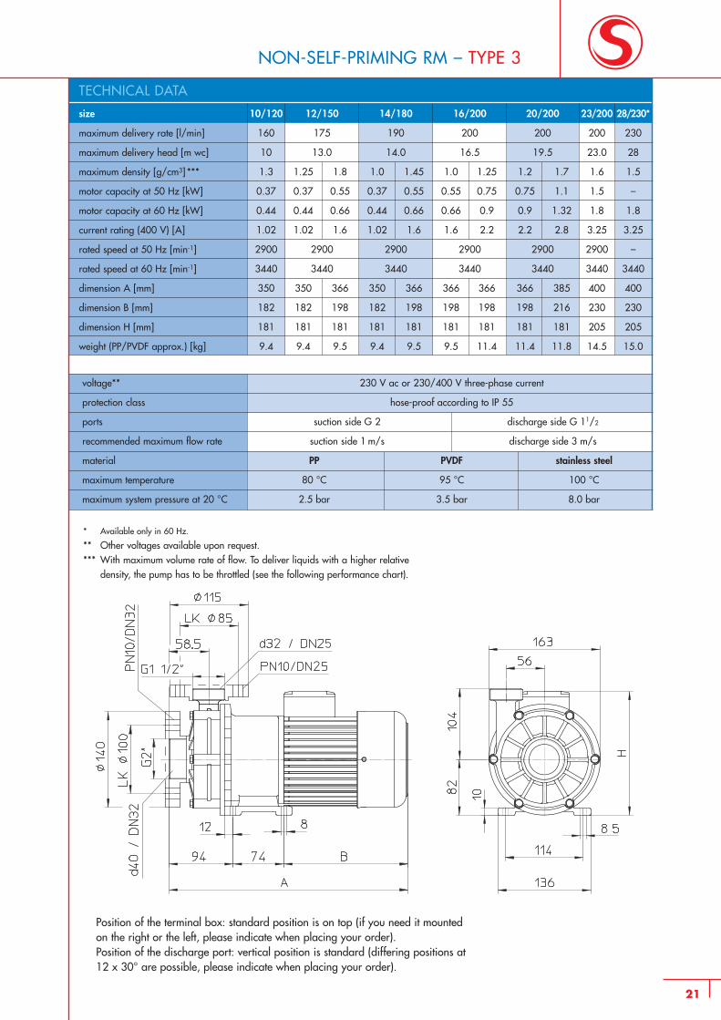
RM MAGNETICALLY COUPLED CENTRIFUGAL PUMPS TYPE 3
Delivery rate up to 200 (230) l/min
Delivery head up to23 (28) m wc
No shaft seal required
For aggressive and neutral liquids
Made of PP or PVDF
Protection class IP 55
Figures in brackets ( ) apply to 60 Hz pump types.
PERFORMANCE CHARTS
STANDARD DESIGN
Housing, impeller and impeller magnetcoating are made of glass-fibre rein-forced PP plastic or PVDF or stainlesssteel. Sleeve bearings, starting ringsand centering shaft are made of 99.7 % pure oxide ceramic, and theO-ring sealing of the housing is madeof either FKM or EPDM. (See table onpage 7 for other materials.)
Magnetically coupled centrifugal pumps of type 3 are non-self-priming pumps that operate in horizontal position and are madein monobloc design. A magnetic coupling connects the pump to the motor and transmits the power of the motor to the impeller.
motor capacity[W]
water at 20 °C
10/120
160
10
1.3
0.37
0.44
1.02
2900
3440
350
182
181
9.4
size
maximum delivery rate [l/min]
maximum delivery head [m wc]
maximum density [g/cm3] ***
motor capacity at 50 Hz [kW]
motor capacity at 60 Hz [kW]
current rating (400 V) [A]
rated speed at 50 Hz [min-1]
rated speed at 60 Hz [min-1]
dimension A [mm]
dimension B [mm]
dimension H [mm]
weight (PP/PVDF approx.) [kg]
12/150
175
13.0
1.25 1.8
0.37 0.55
0.44 0.66
1.02 1.6
2900
3440
350 366
182 198
181 181
9.4 9.5
14/180
190
14.0
1.0 1.45
0.37 0.55
0.44 0.66
1.02 1.6
2900
3440
350 366
182 198
181 181
9.4 9.5
16/200
200
16.5
1.0 1.25
0.55 0.75
0.66 0.9
1.6 2.2
2900
3440
366 366
198 198
181 181
9.5 11.4
20/200
200
19.5
1.2 1.7
0.75 1.1
0.9 1.32
2.2 2.8
2900
3440
366 385
198 216
181 181
11.4 11.8
23/200
200
23.0
1.6
1.5
1.8
3.25
2900
3440
400
230
205
14.5
28/230*
230
28
1.5
–
1.8
3.25
–
3440
400
230
205
15.0
TECHNICAL DATA
voltage** 230 V ac or 230/400 V three-phase current
protection class hose-proof according to IP 55
ports suction side G 2 discharge side G 11/2
recommended maximum flow rate suction side 1 m/s discharge side 3 m/s
material PP PVDF stainless steel
maximum temperature 80 °C 95 °C 100 °C
maximum system pressure at 20 °C 2.5 bar 3.5 bar 8.0 bar
21
NON-SELF-PRIMING RM – TYPE 3
* Available only in 60 Hz.
** Other voltages available upon request.*** With maximum volume rate of flow. To deliver liquids with a higher relative
density, the pump has to be throttled (see the following performance chart).
Position of the terminal box: standard position is on top (if you need it mounted on the right or the left, please indicate when placing your order). Position of the discharge port: vertical position is standard (differing positions at 12 x 30° are possible, please indicate when placing your order).
22
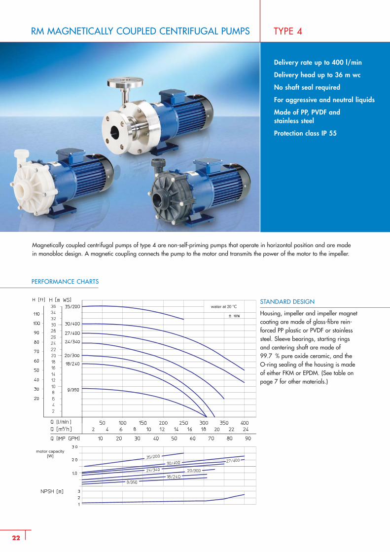
RM MAGNETICALLY COUPLED CENTRIFUGAL PUMPS TYPE 4
Delivery rate up to 400 l/min
Delivery head up to 36 m wc
No shaft seal required
For aggressive and neutral liquids
Made of PP, PVDF andstainless steel
Protection class IP 55
Magnetically coupled centrifugal pumps of type 4 are non-self-priming pumps that operate in horizontal position and are madein monobloc design. A magnetic coupling connects the pump to the motor and transmits the power of the motor to the impeller.
PERFORMANCE CHARTS
STANDARD DESIGN
Housing, impeller and impeller magnetcoating are made of glass-fibre rein-forced PP plastic or PVDF or stainlesssteel. Sleeve bearings, starting ringsand centering shaft are made of 99.7 % pure oxide ceramic, and theO-ring sealing of the housing is madeof either FKM or EPDM. (See table onpage 7 for other materials.)
motor capacity[W]
water at 20 °C
9/350
305
9.0
1.25
0.75
0.9
2.1
1450
1750
430
227
17.0
size
maximum delivery rate [l/min]
maximum delivery head [m wc]
maximum density [g/cm3] ***
motor capacity at 50 Hz [kW]
motor capacity at 60 Hz [kW]
current rating (400 V) [A]
rated speed at 50 Hz [min-1]
rated speed at 60 Hz [min-1]
dimension A [mm]
dimension H [mm]
weight (PP/PVDF approx.) [kg]
18/240
310
17.5
0.8 1.25 1.6
0.75 1.1 1.5
0.9 1.32 1.8
2.2 2.8 3.25
2900
3440
400 457 474
220 220 220
13.0 15.5 18.0
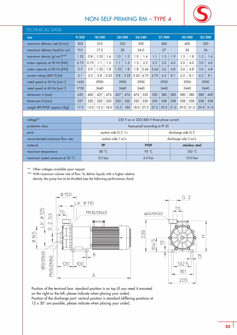
TECHNICAL DATA
voltage** 230 V ac or 230/400 V three-phase current
protection class hose-proof according to IP 55
ports suction side G 2 1/4 discharge side G 2
recommended maximum flow rate suction side 1 m/s discharge side 3 m/s
material PP PVDF stainless steel
maximum temperature 80 °C 95 °C 100 °C
maximum system pressure at 20 °C 5.0 bar 6.0 bar 10.0 bar
20/300
325
20
1.0 1.2
1.1 1.5
1.32 1.8
2.8 3.25
2900
3440
457 474
220 220
15.5 180
24/340
350
24.0
1.0 1.4
1.5 2.2
1.8 2.64
3.25 4.75
2900
3440
474 530
220 230
18.0 27.5
30/400
400
30
1.3 1.8
3.0 4.0
3.6 4.8
6.2 8.1
2900
3440
580 580
258 258
29.0 31.0
35/200
250
36
1.2 1.6
3.0 4.0
3.6 4.8
6.2 8.1
2900
3440
580 600
258 258
29.0 31.0
27/400
400
27
1.1 1.5 1.9
2.2 3.0 4.0
2.64 3.6 4.8
4.75 6.2 8.1
2900
3440
530 580 580
230 258 258
27.5 29.0 31.0
23
NON-SELF-PRIMING RM – TYPE 4
** Other voltages available upon request.*** With maximum volume rate of flow. To deliver liquids with a higher relative
density, the pump has to be throttled (see the following performance chart).
Position of the terminal box: standard position is on top (if you need it mounted on the right or the left, please indicate when placing your order).Position of the discharge port: vertical position is standard (differing positions at 12 x 30° are possible, please indicate when placing your order).
24
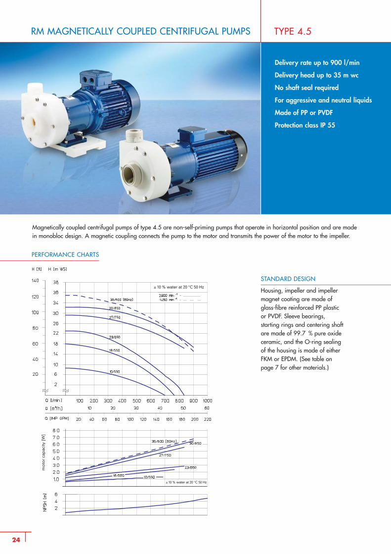
RM MAGNETICALLY COUPLED CENTRIFUGAL PUMPS TYPE 4.5
Delivery rate up to 900 l/min
Delivery head up to 35 m wc
No shaft seal required
For aggressive and neutral liquids
Made of PP or PVDF
Protection class IP 55
Magnetically coupled centrifugal pumps of type 4.5 are non-self-priming pumps that operate in horizontal position and are madein monobloc design. A magnetic coupling connects the pump to the motor and transmits the power of the motor to the impeller.
PERFORMANCE CHARTS
STANDARD DESIGN
Housing, impeller and impellermagnet coating are made of glass-fibre reinforced PP plastic or PVDF. Sleeve bearings, starting rings and centering shaft are made of 99.7 % pure oxide ceramic, and the O-ring sealing of the housing is made of either FKM or EPDM. (See table on page 7 for other materials.)
mo
tor
cap
acity
[W
]
± 10 % water at 20 °C 50 Hz
± 10 % water at 20 °C 50 Hz
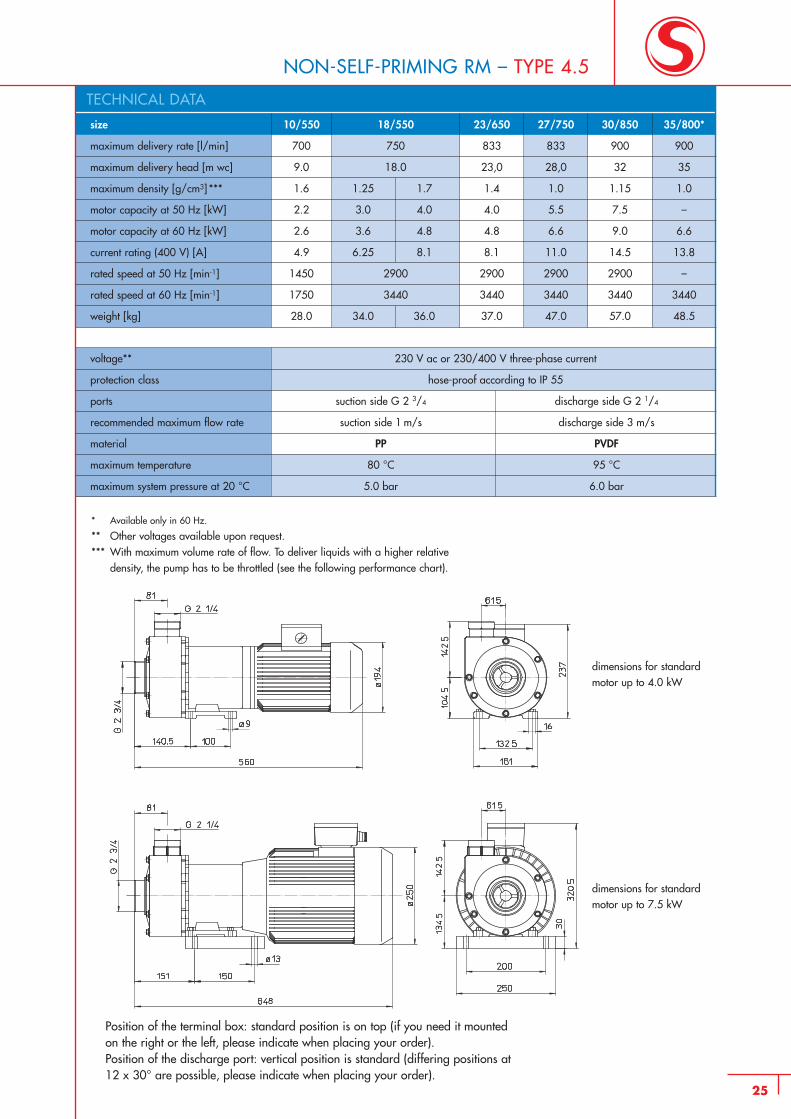
10/550
700
9.0
1.6
2.2
2.6
4.9
1450
1750
28.0
size
maximum delivery rate [l/min]
maximum delivery head [m wc]
maximum density [g/cm3] ***
motor capacity at 50 Hz [kW]
motor capacity at 60 Hz [kW]
current rating (400 V) [A]
rated speed at 50 Hz [min-1]
rated speed at 60 Hz [min-1]
weight [kg]
23/650
833
23,0
1.4
4.0
4.8
8.1
2900
3440
37.0
27/750
833
28,0
1.0
5.5
6.6
11.0
2900
3440
47.0
30/850
900
32
1.15
7.5
9.0
14.5
2900
3440
57.0
35/800*
900
35
1.0
–
6.6
13.8
–
3440
48.5
18/550
750
18.0
1.25 1.7
3.0 4.0
3.6 4.8
6.25 8.1
2900
3440
34.0 36.0
voltage** 230 V ac or 230/400 V three-phase current
protection class hose-proof according to IP 55
ports suction side G 2 3/4 discharge side G 2 1/4
recommended maximum flow rate suction side 1 m/s discharge side 3 m/s
material PP PVDF
maximum temperature 80 °C 95 °C
maximum system pressure at 20 °C 5.0 bar 6.0 bar
25
NON-SELF-PRIMING RM – TYPE 4.5
* Available only in 60 Hz.
** Other voltages available upon request.*** With maximum volume rate of flow. To deliver liquids with a higher relative
density, the pump has to be throttled (see the following performance chart).
Position of the terminal box: standard position is on top (if you need it mounted on the right or the left, please indicate when placing your order).Position of the discharge port: vertical position is standard (differing positions at 12 x 30° are possible, please indicate when placing your order).
TECHNICAL DATA
dimensions for standardmotor up to 4.0 kW
dimensions for standardmotor up to 7.5 kW
26
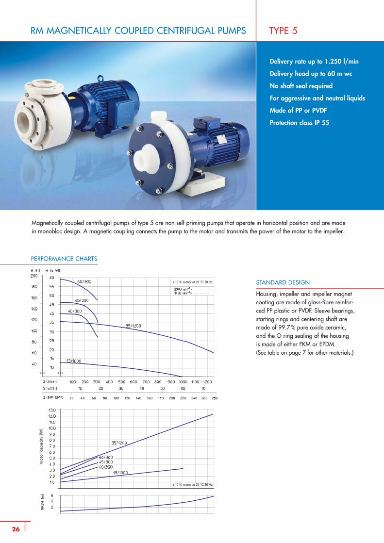
RM MAGNETICALLY COUPLED CENTRIFUGAL PUMPS TYPE 5
Delivery rate up to 1.250 l/min
Delivery head up to 60 m wc
No shaft seal required
For aggressive and neutral liquids
Made of PP or PVDF
Protection class IP 55
PERFORMANCE CHARTS
Magnetically coupled centrifugal pumps of type 5 are non-self-priming pumps that operate in horizontal position and are madein monobloc design. A magnetic coupling connects the pump to the motor and transmits the power of the motor to the impeller.
STANDARD DESIGN
Housing, impeller and impeller magnetcoating are made of glass-fibre reinfor-ced PP plastic or PVDF. Sleeve bearings,starting rings and centering shaft aremade of 99.7 % pure oxide ceramic,and the O-ring sealing of the housing is made of either FKM or EPDM.(See table on page 7 for other materials.)
mo
tor
cap
acity
[W
]
± 10 % water at 20 °C 50 Hz
± 10 % water at 20 °C 50 Hz
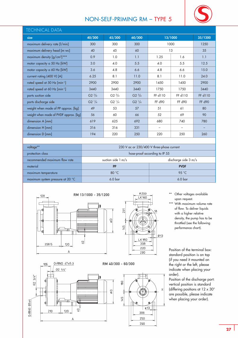
40/300
300
40
0.9
3.0
3.6
6.25
2900
3440
G2 3/4
G2 1/4
49
56
619
316
194
size
maximum delivery rate [l/min]
maximum delivery head [m wc]
maximum density [g/cm3] ***
motor capacity a 50 Hz [kW]
motor capacity a 60 Hz [kW]
current rating (400 V) [A]
rated speed at 50 Hz [min-1]
rated speed at 60 Hz [min-1]
ports suction side
ports discharge side
weight when made of PP approx. [kg]
weight when made of PVDF approx. [kg]
dimension A [mm]
dimension H [mm]
dimension D [mm]
45/300
300
45
1.0
4.0
4.8
8.1
2900
3440
G2 3/4
G2 1/4
53
60
625
316
220
60/300
300
60
1.1
5.5
6.6
11.0
2900
3440
G2 3/4
G2 1/4
57
66
692
331
250
35/1200
1250
35
1.1
12.5
15.0
24.0
2900
3440
FF d110
FF d90
80
90
780
–
260
13/1000
1000
13
1.25 1.6
4.0 5.5
4.8 6.6
8.1 11.0
1450 1450
1750 1750
FF d110 FF d110
FF d90 FF d90
51 61
52 69
680 740
– –
220 250
voltage** 230 V ac or 230/400 V three-phase current
protection class hose-proof according to IP 55
recommended maximum flow rate suction side 1 m/s discharge side 3 m/s
material PP PVDF
maximum temperature 80 °C 95 °C
maximum system pressure at 20 °C 6.0 bar 6.0 bar
27
NON-SELF-PRIMING RM – TYPE 5
** Other voltages availableupon request.
*** With maximum volume rateof flow. To deliver liquids with a higher relative density, the pump has to bethrottled (see the followingperformance chart).
Position of the terminal box:standard position is on top(if you need it mounted onthe right or the left, pleaseindicate when placing yourorder).Position of the discharge port:vertical position is standard(differing positions at 12 x 30°are possible, please indicatewhen placing your order).
RM 13/1000 - 35/1200
RM 40/300 - 60/300
TECHNICAL DATA
28
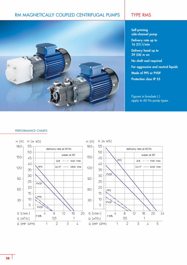
RM MAGNETICALLY COUPLED CENTRIFUGAL PUMPS TYPE RMS
Self-priming side-channel pump
Delivery rate up to 16 (21) l/min
Delivery head up to 39 (54) m wc
No shaft seal required
For aggressive and neutral liquids
Made of PPS or PVDF
Protection class IP 55
Figures in brackets ( ) apply to 60 Hz pump types.
PERFORMANCE CHARTS
delivery rate at 50 Hz
water at 20° water at 20°
delivery rate at 50 Hz
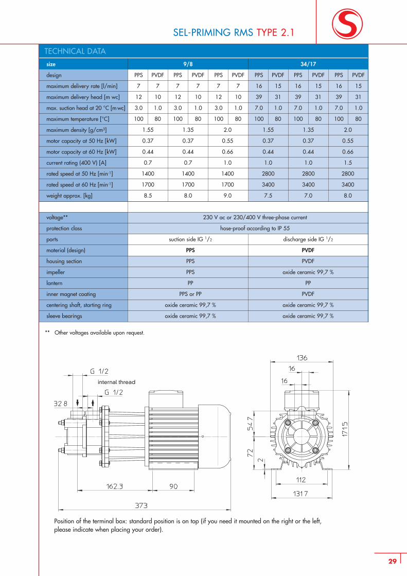
9/8
PPS PVDF PPS PVDF PPS PVDF
7 7 7 7 7 7
12 10 12 10 12 10
3.0 1.0 3.0 1.0 3.0 1.0
100 80 100 80 100 80
1.55 1.35 2.0
0.37 0.37 0.55
0.44 0.44 0.66
0.7 0.7 1.0
1400 1400 1400
1700 1700 1700
8.5 8.0 9.0
size
design
maximum delivery rate [l/min]
maximum delivery head [m wc]
max. suction head at 20 °C [m wc]
maximum temperature [°C]
maximum density [g/cm3]
motor capacity at 50 Hz [kW]
motor capacity at 60 Hz [kW]
current rating (400 V) [A]
rated speed at 50 Hz [min-1]
rated speed at 60 Hz [min-1]
weight approx. [kg]
34/17
PPS PVDF PPS PVDF PPS PVDF
16 15 16 15 16 15
39 31 39 31 39 31
7.0 1.0 7.0 1.0 7.0 1.0
100 80 100 80 100 80
1.55 1.35 2.0
0.37 0.37 0.55
0.44 0.44 0.66
1.0 1.0 1.5
2800 2800 2800
3400 3400 3400
7.5 7.0 8.0
voltage** 230 V ac or 230/400 V three-phase current
protection class hose-proof according to IP 55
ports suction side IG 1/2 discharge side IG 1/2
material (design) PPS PVDF
housing section PPS PVDF
impeller PPS oxide ceramic 99,7 %
lantern PP PP
inner magnet coating PPS or PP PVDF
centering shaft, starting ring oxide ceramic 99,7 % oxide ceramic 99,7 %
sleeve bearings oxide ceramic 99,7 % oxide ceramic 99,7 %
SEL-PRIMING RMS TYPE 2.1
29
** Other voltages available upon request.
Position of the terminal box: standard position is on top (if you need it mounted on the right or the left,please indicate when placing your order).
TECHNICAL DATA
internal thread
30
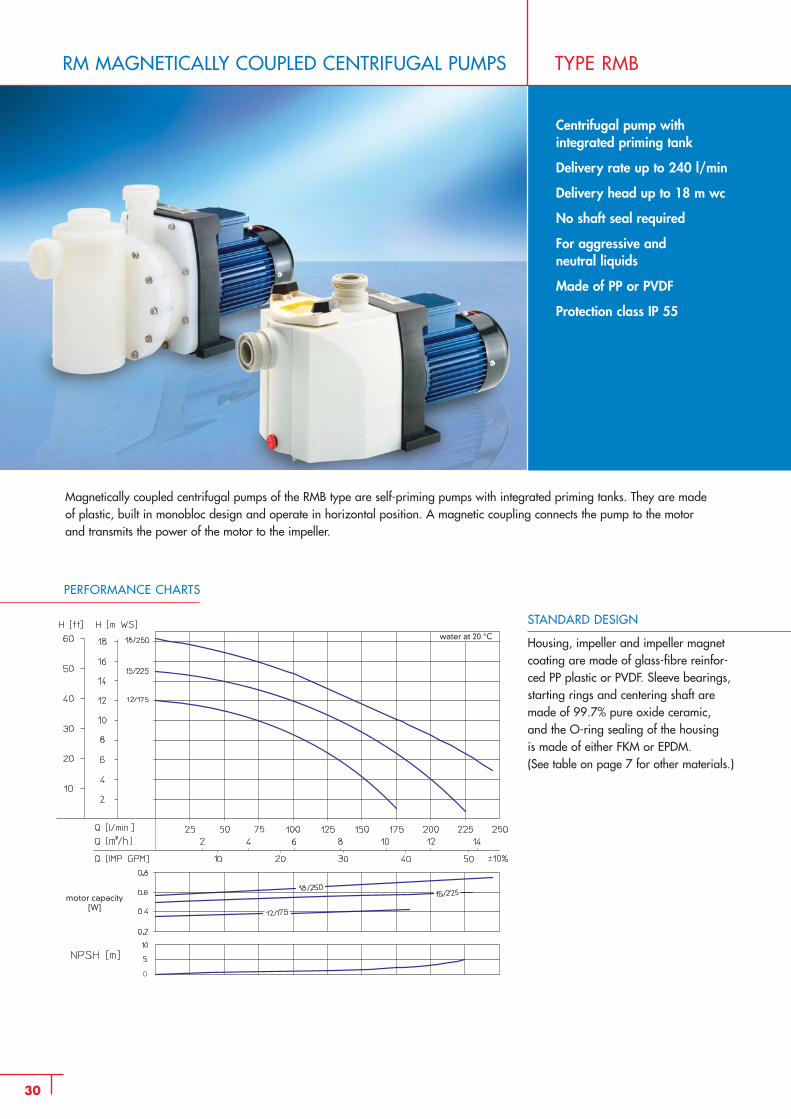
RM MAGNETICALLY COUPLED CENTRIFUGAL PUMPS TYPE RMB
Centrifugal pump with integrated priming tank
Delivery rate up to 240 l/min
Delivery head up to 18 m wc
No shaft seal required
For aggressive and neutral liquids
Made of PP or PVDF
Protection class IP 55
PERFORMANCE CHARTS
Magnetically coupled centrifugal pumps of the RMB type are self-priming pumps with integrated priming tanks. They are madeof plastic, built in monobloc design and operate in horizontal position. A magnetic coupling connects the pump to the motorand transmits the power of the motor to the impeller.
STANDARD DESIGN
Housing, impeller and impeller magnetcoating are made of glass-fibre reinfor-ced PP plastic or PVDF. Sleeve bearings,starting rings and centering shaft aremade of 99.7% pure oxide ceramic, and the O-ring sealing of the housing is made of either FKM or EPDM.(See table on page 7 for other materials.)
water at 20 °C
motor capacity[W]
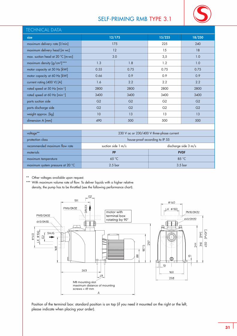
12/175
175
12
3.0
1.3 1.8
0.55 0.75
0.66 0.9
1.6 2.2
2800 2800
3400 3400
G2 G2
G2 G2
10 13
490 500
size
maximum delivery rate [l/min]
maximum delivery head [m wc]
max. suction head at 20 °C [m wc]
maximum density [g/cm3] ***
motor capacity at 50 Hz [kW]
motor capacity at 60 Hz [kW]
current rating (400 V) [A]
rated speed at 50 Hz [min-1]
rated speed at 60 Hz [min-1]
parts suction side
ports discharge side
weight approx. [kg]
dimension A [mm]
15/225
225
15
3,5
1.2
0.75
0.9
2.2
2800
3400
G2
G2
13
500
18/250
240
18
1.0
1.0
0.75
0.9
2.2
2800
3400
G2
G2
13
500
voltage** 230 V ac or 230/400 V three-phase current
protection class house-proof according to IP 55
recommended maximum flow rate suction side 1 m/s discharge side 3 m/s
materials PP PVDF
maximum temperature 65 °C 85 °C
maximum system pressure at 20 °C 2.5 bar 3.5 bar
31
SELF-PRIMING RMB TYPE 3.1
** Other voltages available upon request.*** With maximum volume rate of flow. To deliver liquids with a higher relative
density, the pump has to be throttled (see the following performance chart).
Position of the terminal box: standard position is on top (if you need it mounted on the right or the left,please indicate when placing your order).
TECHNICAL DATA
motor withterminal boxrotating by 90°
M8 mounting slotmaximum distance of mounting screws = 49 mm
32
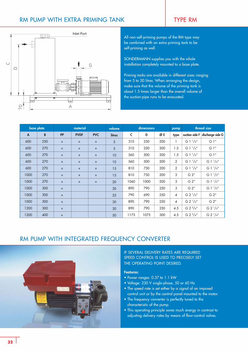
RM PUMP WITH EXTRA PRIMING TANK TYPE RM
All non-self-priming pumps of the RM type maybe combined with an extra priming tank to beself-priming as well.
SONDERMANN supplies you with the whole installation completely mounted to a base plate.
Priming tanks are available in different sizes rangingfrom 5 to 50 litres. When arranging the design,make sure that the volume of the priming tank is about 1.5 times larger than the overall volume of the suction-pipe runs to be evacuated.
base plate
A B
600 250
600 270
600 270
600 270
600 270
1000 270
1000 270
1000 300
1000 300
1000 300
1200 300
1200 400
material
PP PVDF PVC
x x x
x x x
x x x
x x x
x x x
x x x
x x x
x
x
x
x
x
thread size
suction side F discharge side G
G 1 1/4“ G 1“
G 1 1/4“ G 1“
G 1 1/4“ G 1“
G 1 1/4“ G 1 1/4“
G 1 1/4“ G 1 1/4“
G 2“ G 1 1/2“
G 2“ G 1 1/2“
G 2“ G 1 1/2“
G 2 1/4“ G 2“
G 2 1/4“ G 2“
G 2 3/4“ G 2 1/4“
G 2 3/4“ G 2 1/4“
dimensions
C D Ø E
310 250 200
310 250 200
560 500 200
560 500 200
810 750 200
810 750 200
1060 1000 200
890 790 250
790 690 250
890 790 250
890 790 250
1175 1075 300
volume
litres
5
5
10
10
15
15
20
30
25
30
30
50
pump
type
1
1.5
1.5
2
2
3
3
3
4
4
4.5
4.5
IF SEVERAL DELIVERY RATES ARE REQUIREDSPEED CONTROL IS USED TO PRECISELY SETTHE OPERATING POINT DESIRED.
Features: • Power ranges: 0.37 to 1.1 kW• Voltage: 230 V single-phase, 50 or 60 Hz• The speed rate is set either by a signal of an imposed
control unit or by the control panel mounted to the motor.• The frequency converter is perfectly tuned to the
characteristic of the pump.• This operating principle saves much energy in contrast to
adjusting delivery rates by means of flow-control valves.
RM PUMP WITH INTEGRATED FREQUENCY CONVERTER
Inlet Port
33
type
2
3
4
5
nominal diameter of suction part
DN 20 PN 10
DN 32 PN 10
DN 50 PN 10
DN 65 PN 10
nominal diameter ofdischarge part
DN 20 PN 10
DN 25 PN 10
DN 40 PN 10
DN 50 PN 10
PPmaterial
X
X
X
X
PVDF material
X
X
X
X
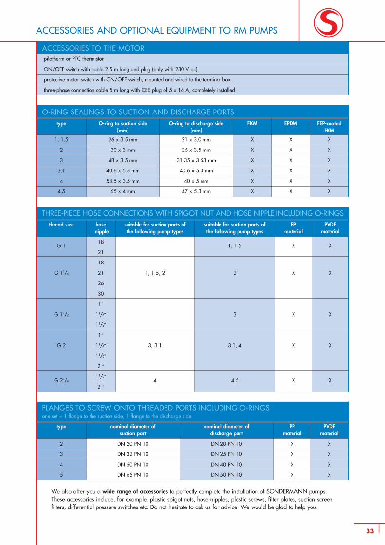
FLANGES TO SCREW ONTO THREADED PORTS INCLUDING O-RINGSone set = 1 flange to the suction side, 1 flange to the discharge side
ACCESSORIES AND OPTIONAL EQUIPMENT TO RM PUMPS
pilotherm or PTC thermistor
ON/OFF switch with cable 2.5 m long and plug (only with 230 V ac)
protective motor switch with ON/OFF switch, mounted and wired to the terminal box
three-phase connection cable 5 m long with CEE plug of 5 x 16 A, completely installed
type
1, 1.5
2
3
3.1
4
4.5
O-ring to suction side[mm]
26 x 3.5 mm
30 x 3 mm
48 x 3.5 mm
40.6 x 5.3 mm
53.5 x 3.5 mm
65 x 4 mm
O-ring to discharge side[mm]
21 x 3.0 mm
26 x 3.5 mm
31.35 x 3.53 mm
40.6 x 5.3 mm
40 x 5 mm
47 x 5.3 mm
FKM
X
X
X
X
X
X
EPDM
X
X
X
X
X
X
FEP-coated FKM
X
X
X
X
X
X
O-RING SEALINGS TO SUCTION AND DISCHARGE PORTS
thread size
G 1
G 11/4
G 11/2
G 2
G 21/4
hosenipple
18
21
18
21
26
30
1“
11/4“
11/2“
1“
11/4“
11/2“
2 “
11/2“
2 “
suitable for suction ports ofthe following pump types
1, 1.5, 2
3, 3.1
4
suitable for suction ports ofthe following pump types
1, 1.5
2
3
3.1, 4
4.5
PPmaterial
X
X
X
X
X
PVDFmaterial
X
X
X
X
X
THREE-PIECE HOSE CONNECTIONS WITH SPIGOT NUT AND HOSE NIPPLE INCLUDING O-RINGS
We also offer you a wide range of accessories to perfectly complete the installation of SONDERMANN pumps.These accessories include, for example, plastic spigot nuts, hose nipples, plastic screws, filter plates, suction screen filters, differential pressure switches etc. Do not hesitate to ask us for advice! We would be glad to help you.
ACCESSORIES TO THE MOTOR
34
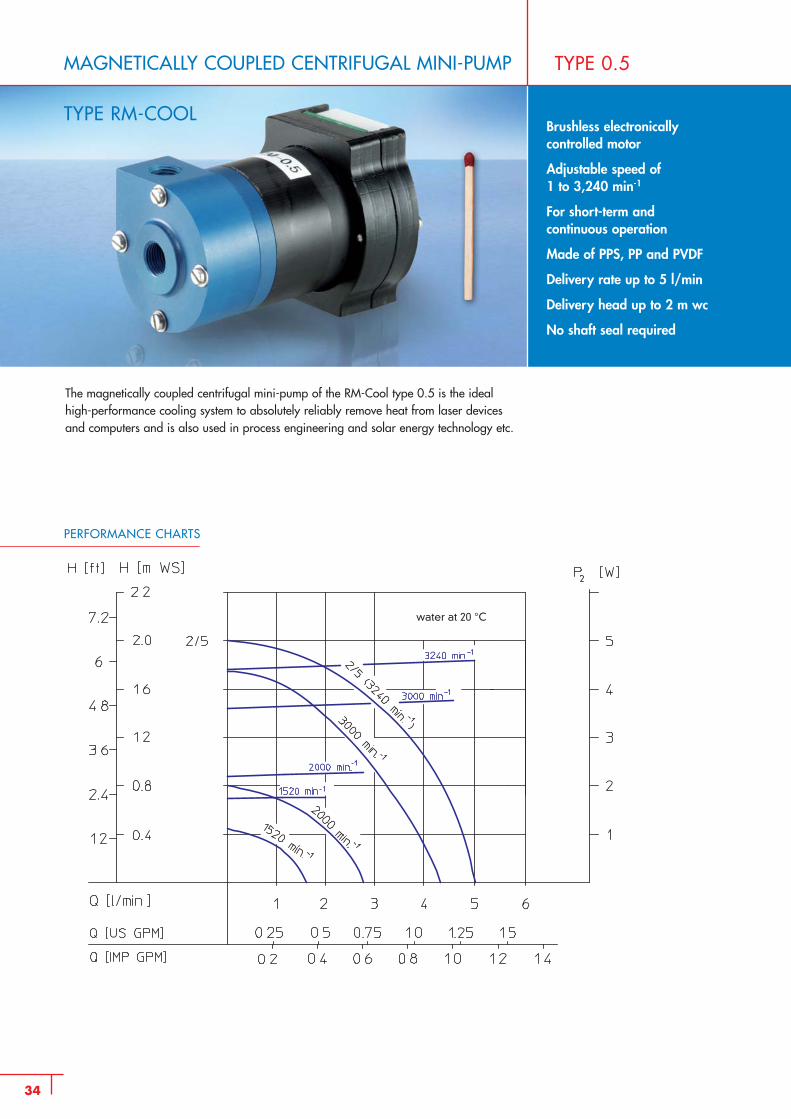
MAGNETICALLY COUPLED CENTRIFUGAL MINI-PUMP
TYPE RM-COOL
TYPE 0.5
Brushless electronicallycontrolled motor
Adjustable speed of 1 to 3,240 min-1
For short-term and continuous operation
Made of PPS, PP and PVDF
Delivery rate up to 5 l/min
Delivery head up to 2 m wc
No shaft seal required
PERFORMANCE CHARTS
The magnetically coupled centrifugal mini-pump of the RM-Cool type 0.5 is the ideal high-performance cooling system to absolutely reliably remove heat from laser devices and computers and is also used in process engineering and solar energy technology etc.
water at 20 °C
35
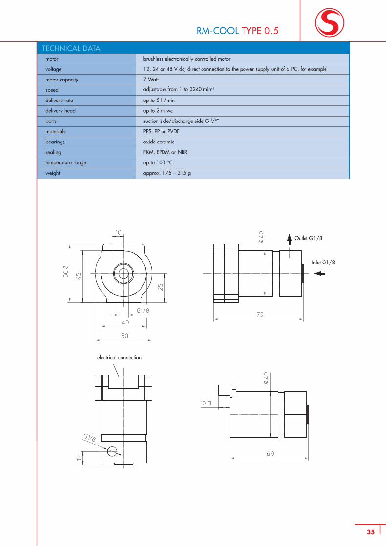
RM-COOL TYPE 0.5
motor brushless electronically controlled motor
voltage 12, 24 or 48 V dc; direct connection to the power supply unit of a PC, for example
motor capacity 7 Watt
speed adjustable from 1 to 3240 min-1
delivery rate up to 5 l /min
delivery head up to 2 m wc
ports suction side/discharge side G 1/8”
materials PPS, PP or PVDF
bearings oxide ceramic
sealing FKM, EPDM or NBR
temperature range up to 100 °C
weight approx. 175 – 215 g
TECHNICAL DATA
electrical connection
Inlet G1/8
Outlet G1/8
36
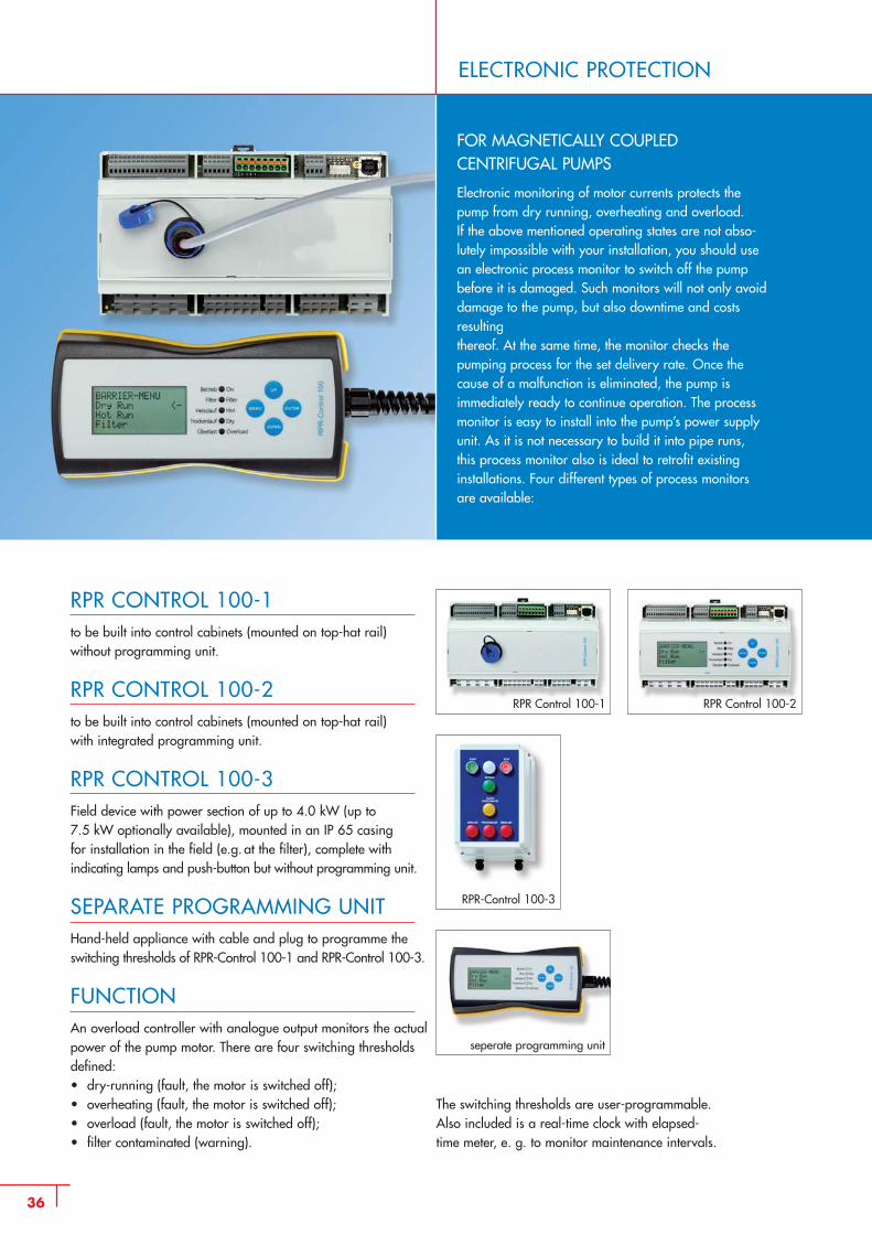
ELECTRONIC PROTECTION
FOR MAGNETICALLY COUPLED CENTRIFUGAL PUMPS
Electronic monitoring of motor currents protects thepump from dry running, overheating and overload. If the above mentioned operating states are not abso-lutely impossible with your installation, you should usean electronic process monitor to switch off the pumpbefore it is damaged. Such monitors will not only avoiddamage to the pump, but also downtime and costsresulting thereof. At the same time, the monitor checks the pumping process for the set delivery rate. Once thecause of a malfunction is eliminated, the pump is immediately ready to continue operation. The processmonitor is easy to install into the pump’s power supplyunit. As it is not necessary to build it into pipe runs, this process monitor also is ideal to retrofit existinginstallations. Four different types of process monitorsare available:
RPR CONTROL 100-1to be built into control cabinets (mounted on top-hat rail) without programming unit.
RPR CONTROL 100-2to be built into control cabinets (mounted on top-hat rail) with integrated programming unit.
RPR CONTROL 100-3Field device with power section of up to 4.0 kW (up to 7.5 kW optionally available), mounted in an IP 65 casing for installation in the field (e.g. at the filter), complete with indicating lamps and push-button but without programming unit.
SEPARATE PROGRAMMING UNITHand-held appliance with cable and plug to programme the switching thresholds of RPR-Control 100-1 and RPR-Control 100-3.
FUNCTIONAn overload controller with analogue output monitors the actualpower of the pump motor. There are four switching thresholdsdefined:• dry-running (fault, the motor is switched off); • overheating (fault, the motor is switched off); • overload (fault, the motor is switched off);• filter contaminated (warning).
RPR Control 100-1 RPR Control 100-2
seperate programming unit
RPR-Control 100-3
The switching thresholds are user-programmable.Also included is a real-time clock with elapsed-time meter, e. g. to monitor maintenance intervals.
37
FLOW MONITORS
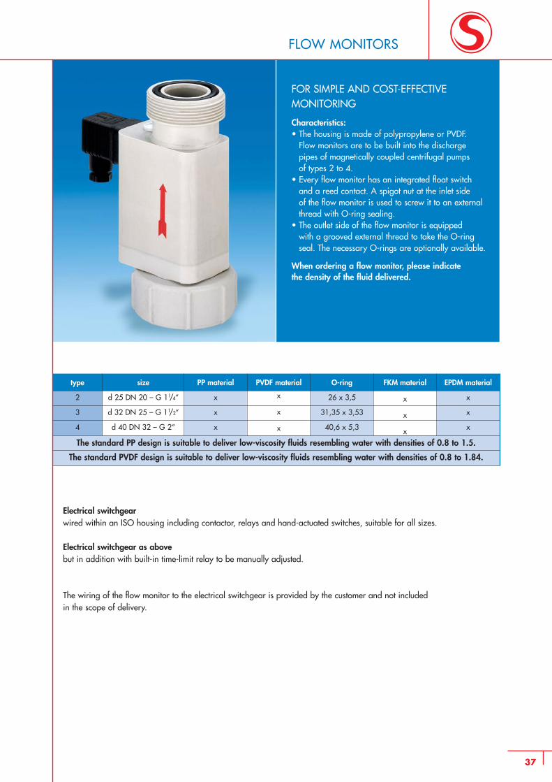
FOR SIMPLE AND COST-EFFECTIVEMONITORING
Characteristics:• The housing is made of polypropylene or PVDF.
Flow monitors are to be built into the discharge pipes of magnetically coupled centrifugal pumps of types 2 to 4.
• Every flow monitor has an integrated float switch and a reed contact. A spigot nut at the inlet side of the flow monitor is used to screw it to an external thread with O-ring sealing.
• The outlet side of the flow monitor is equipped with a grooved external thread to take the O-ring seal. The necessary O-rings are optionally available.
When ordering a flow monitor, please indicate the density of the fluid delivered.
Electrical switchgear wired within an ISO housing including contactor, relays and hand-actuated switches, suitable for all sizes.
Electrical switchgear as above but in addition with built-in time-limit relay to be manually adjusted.
The wiring of the flow monitor to the electrical switchgear is provided by the customer and not includedin the scope of delivery.
The standard PP design is suitable to deliver low-viscosity fluids resembling water with densities of 0.8 to 1.5.
The standard PVDF design is suitable to deliver low-viscosity fluids resembling water with densities of 0.8 to 1.84.
type
2
3
4
size
d 25 DN 20 – G 11/4“
d 32 DN 25 – G 11/2“
d 40 DN 32 – G 2“
PP material
x
x
x
PVDF material
x
x
x
O-ring
26 x 3,5
31,35 x 3,53
40,6 x 5,3
FKM material
x
x
x
EPDM material
x
x
x
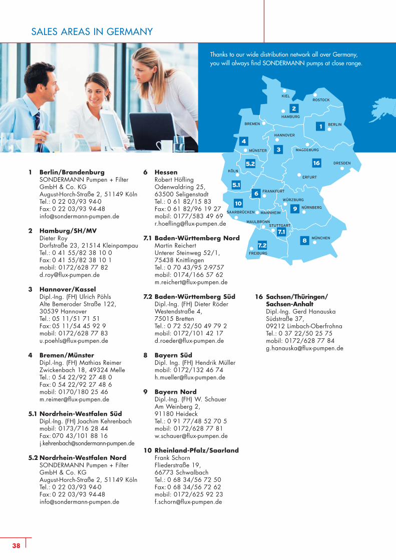
SALES AREAS IN GERMANY
KIELROSTOCK
HAMBURG
BREMEN
HANNOVER
BERLIN
MÜNSTER
KÖLN
ERFURT
FRANKFURT
WÜRZBURG
NÜRNBERG
MANNHEIM
MAULBRONN
SAARBRÜCKEN
STUTTGART
MÜNCHEN
FREIBURG
MAGDEBURG
DRESDEN
1
2
4
3
5.1
165.2
6
109
7.2
7.1
8
1 Berlin/BrandenburgSONDERMANN Pumpen + Filter GmbH & Co. KGAugust-Horch-Straße 2, 51149 KölnTel.: 0 22 03/93 94-0Fax: 0 22 03/93 [email protected]
2 Hamburg/SH/MVDieter RoyDorfstraße 23, 21514 KleinpampauTel.: 0 41 55/82 38 10 0Fax: 0 41 55/82 38 10 1mobil: 0172/628 77 [email protected]
3 Hannover/KasselDipl.-Ing. (FH) Ulrich PöhlsAlte Bemeroder Straße 122, 30539 HannoverTel.: 05 11/51 71 51Fax: 05 11/54 45 92 9mobil: 0172/628 77 [email protected]
4 Bremen/MünsterDipl.-Ing. (FH) Mathias ReimerZwickenbach 18, 49324 MelleTel.: 0 54 22/92 27 48 0Fax: 0 54 22/92 27 48 6mobil: 0170/180 25 [email protected]
5.1 Nordrhein-Westfalen SüdDipl.-Ing. (FH) Joachim Kehrenbachmobil: 0173/716 28 44Fax: 070 43/101 88 [email protected]
5.2 Nordrhein-Westfalen NordSONDERMANN Pumpen + Filter GmbH & Co. KGAugust-Horch-Straße 2, 51149 KölnTel.: 0 22 03/93 94-0Fax: 0 22 03/93 [email protected]
6 HessenRobert HöflingOdenwaldring 25,63500 SeligenstadtTel.: 0 61 82/15 83Fax: 0 61 82/96 19 27mobil: 0177/583 49 [email protected]
7.1 Baden-Württemberg NordMartin ReichertUnterer Steinweg 52/1,75438 KnittlingenTel.: 0 70 43/95 2-9757mobil: 0174/166 57 [email protected]
7.2 Baden-Württemberg SüdDipl.-Ing. (FH) Dieter RöderWestendstraße 4, 75015 BrettenTel.: 0 72 52/50 49 79 2mobil: 0172/101 42 [email protected]
8 Bayern SüdDipl. Ing. (FH) Hendrik Müllermobil: 0172/132 46 [email protected]
9 Bayern NordDipl.-Ing. (FH) W. SchauerAm Weinberg 2,91180 HeideckTel.: 0 91 77/48 52 70 5mobil: 0172/628 77 [email protected]
10 Rheinland-Pfalz/SaarlandFrank SchornFliederstraße 19, 66773 SchwalbachTel.: 0 68 34/56 72 50Fax: 0 68 34/56 72 62mobil: 0172/625 92 [email protected]
16 Sachsen/Thüringen/Sachsen-AnhaltDipl.-Ing. Gerd HanauskaSüdstraße 37,09212 Limbach-OberfrohnaTel.: 0 37 22/50 25 75mobil: 0172/628 77 [email protected]
Thanks to our wide distribution network all over Germany,you will always find SONDERMANN pumps at close range.
38
39
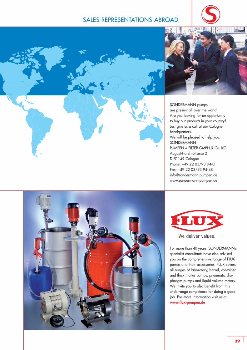
SALES REPRESENTATIONS ABROAD
SONDERMANN pumps are present all over the world. Are you looking for an opportunity to buy our products in your country?Just give us a call at our Cologneheadquarters.We will be pleased to help you.SONDERMANN PUMPEN + FILTER GMBH & Co. KGAugust-Horch-Strasse 2 D-51149 Cologne Phone: +49 22 03/93 94-0 Fax: +49 22 03/93 [email protected]
For more than 40 years, SONDERMANN’sspecialist consultants have also advised you on the comprehensive range of FLUXpumps and their accessories. FLUX coversall ranges of laboratory, barrel, containerand thick matter pumps, pneumatic dia-phragm pumps and liquid volume meters.We invite you to also benefit from this wide-range competence for doing a goodjob. For more information visit us at www.flux-pumpen.de
We deliver values.
August-Horch-Straße 2 · D-51149 ColognePhone +49 (0) 22 03/93 94-0 Fax +49 (0) 22 03/93 [email protected]
SRM
12/
14-P
DF-
GB
Subject to technical alterations