magnetic island dynamics induced by rotating magnetic ... · abstract magnetic island dynamics...
TRANSCRIPT
Magnetic Island Dynamics
Induced by Rotating Magnetic Perturbations
in Tokamak plasma
David Alan Maurer
Submitted in partial fulfillment of the
requirements for the degree
of Doctor of Philosophy
in the Graduate School of Arts and Sciences
COLUMBIA UNIVERSITY

2000
© 2000
David Alan MaurerAll Rights Reserved
ABSTRACT
Magnetic Island DynamicsInduced by Rotating Magnetic Perturbations
in Tokamak plasma
David Alan Maurer
This thesis reports the results of active rotation control experiments of magnetic
islands on the HBT-EP tokamak. A compact modular saddle coil set generates
magnetic perturbations used to apply local torque to pre-existing m/n=2/1
magnetic islands. Here m and n are the poloidal and toroidal mode numbers of
the island structure. Factor of approximately 2 change in island frequency is
observed during these magnetic stirring experiments with an applied radial
saddle coil field of the order of the poloidal field fluctuation of the island
measured at the edge of the plasma. To better quantify the coil-island interaction
a simple cylindrical model of the electromagnetic, inertial, and viscous torque
balance near a large amplitude magnetic island is developed and compared to
experimental island frequency locking torque requirements. The measured order
of magnitude of the electromagnetic torque required to frequency lock HBT-EP
islands is consistent with toroidally driven island motion by these rotating
resonant magnetic perturbations. This observation supports the inclusion of
poloidal flow damping physics in describing HBT-EP magnetic island dynamics.
To ascertain the effect of viscous coupling to the core plasma region and aid in
estimates of magnetic island size, island induced emissivity fluctuations are
studied and an average current profile constructed. Using these emissivity
fluctuations the rotation of the core m/n=1/1 island is observed to be strongly
coupled to that of the edge m/n=2/1 island for both natural propagation and
during active rotation of the 2/1 surface. This thesis concludes with observations
of magnetic island amplitude dynamics during these rotation control
experiments. Island amplitude behavior is complex and reveals the existence of
a frequency dependent amplitude effect when the rotation rate of the magnetic
island is changed from its natural pre-existing speed. HBT-EP magnetic islands
are observed to grow when accelerated and are suppressed or damped when the
magnetic island is decelerated during rotation control experiments. This
response is consistent with order of magnitude estimates of the inertial current
driven by changes in island rotation including the effect of poloidal flow
damping on ion inertia. Damping of poloidal plasma rotation leads to an
effective increase in perpendicular plasma inertia due to coupling of transverse
and longitudinal flow across and along the magnetic field. The observed
asymmetry in growth and damping with acceleration and deceleration of these
magnetic islands is consistent with a destabilizing inertial contribution to the
island width evolution equation of motion. Inspired by the possibility of a
frequency modulated asynchronous control perturbation having an influence on
island size, these perturbations, when applied to disruptive target plasma, were
observed to mitigate core thermal and particle loss. This discovery offers the
possibility of a simple control technique to ameliorate the consequences of
sudden discharge termination from plasma disruption.
i
TABLE OF CONTENTS
1.0 Introduction 1
1.1. Fusion plasma 5
1.2. Magnetic confinement 7
1.3. Magnetic field structure and magnetic islands 10
1.4. Plasma response and magnetic island formation 14
1.5. Resonant magnetic perturbation research 19
1.6. Principal results and thesis outline 22
2.0 HBT-EP machine description 25
3.0 HBT-EP magnetic islandography 33
3.1 External magnetic mode analysis 35
3.2. Emissivity measurements of magnetic islands 37
3.2.1 An introduction 37
3.2.2 Emissivity and its relation to plasma parameters 38
3.2.3 Soft x-ray m=2 magnetic island observations 41
3.2.4 m=2 fluctuation amplitude, phase and frequency 46
3.3 Sawtooth oscillations and m/n=1/1 mode diagnosis 49
3.3.1 Sawtooth phenomenology and HBT-EP sawteeth 53
3.3.2 Singular value decomposition and m/n=1/1
island diagnosis 56
3.4 Current profile model and magnetic island size 67
3.4.1 Magnetic shear scale length estimates 69
3.4.2 Vacuum island width estimates 73
4.0 Rotation control using resonant magnetic perturbations 75
ii
4.1 HBT-EP magnetic island control system 77
4.2 Magnetic island frequency locking 80
4.2.1 Torque balance near a large amplitude island 84
4.2.1.1 Saddle coil electromagnetic torque 83
4.2.1.2 Plasma viscous torque response 86
4.2.1.3 Magnetic island inertial torque 93
4.2.2 Torque balance summary: poloidal flow damping 97
4.2.3 Rotation control implications of m/n=1/1 island motion 100
4.3 Magnetic island amplitude dynamics 103
4.3.1 Asymmetric island amplitude growth and suppression 103
4.3.1.1 Ion polarization physics and island rotation 109
4.3.1.2 Asymmetric amplitude response and ion inertia 115
4.3.2 Disruption mitigation using asynchronous control fields 120
5.0 Summary and conclusions 122
References 125

iii
To my love, Renée
iv
ACKNOWLEDGEMENTS
I would like to start by thanking my advisor Professor Jerry Navratil for
sticking it out with me through all these years of hard work. I have been more
than challenged by working for him on HBT-EP than I thought possible. I hope
some of his great intuition and insight into plasma physics has rubbed-off after
working together these years. I also owe a large debt of thanks to Professor Mike
Mauel for his enthusiasm and perspective during the course of this thesis work.
Mike is always willing to discuss and debate questions about HBT-EP magnetic
island physics and this is a better thesis as a result of his help. I would also like
to thank Professor Allen Boozer for his open door policy and readiness to answer
or work through perhaps not quite well formulated questions.
Marlene Arbo and Lydia Argote deserve special mention. I am grateful to you
both for helping me navigate the myriad intricacies of Columbia and its
wonderful bureaucracy with good cheer and humor. You both make the
Applied Physics and Applied Mathematics department a special one to attend.
There is no possible way this thesis would have been finished were it not for
the efforts of Nick Rivera, Estuardo Rodas, and Maurice Cea. Their finger prints
might not be directly visible in the pages that follow, but there hard work,
insight, and ability to make the Columbia Plasma Physics Laboratory a place that
works form the backbone or foundation upon which this thesis was built. I thank
them all and look forward to keeping in close contact in the future.
I have been lucky to be part of the original HBT-EP gang. I would like to thank
all of this old crew as well as the new generation of graduate students and

v
scientists. Thanks go to Tom Ivers, Raed Kombargi, Andrea Garofalo, Xiao
Qingjun, Ned Eisner, and David Nadle. Without their help and humor the lab
would have been a very dull place indeed. To the new generation, I would like
to thank Cory Cates, Mikhail Shilov, Suparna Mukherjee, and Hossein Dahi for
all their understanding and help during the last years of this work.
Lastly and most importantly, I would like to thank my family for all their
support over these many years of graduate school. Thank you Mom and Dad for
all the help and support during these years in New York, and of course all those
that went before it. Renée and I both owe you more than words can say. Finally,
I would like to thank Renée, who stood by me and supported me throughout. I
would have drowned without you my love. I dedicate this thesis to you.

1
Every time you look up at the sky, every one of those pointsof light is a reminder that fusion power is extractable fromhydrogen and other light elements, and it is an everyday realitythroughout the Milky Way Galaxy.
- Carl Sagan, Spitzer Lecture, Princeton University, October 1991
1.0 Introduction
Fusion energy, the source of power for our sun and other stars in the sky
above, is at present the preferred method of power production throughout our
universe. All the bright points of light in the night time sky attest to this fact.
Unfortunately the same situation is not an everyday reality here on planet earth.
To date, the quest of developing an analogous terrestrial-based fusion power
source capable of generating billion Watt thermal power levels has occupied the
concentrated efforts of research scientists and engineers for a span of some fifty
years during the last half of the twentieth century. Pursuit of this grand
challenge goal to bring the power source of the sun and stars down to earth,
while much nearer to being reality than it was during its inception, is still on the
horizon of our scientific and technical experience.
Steady progress has been made in advancing necessary plasma parameter
values into the range required for significant fusion energy generation over this
period of time. Earth-based laboratory plasmas can now be generated with
temperatures higher than the center of our own sun confined by magnetic fields
for long periods of time. Up to 10 million Watts of fusion power production and
2
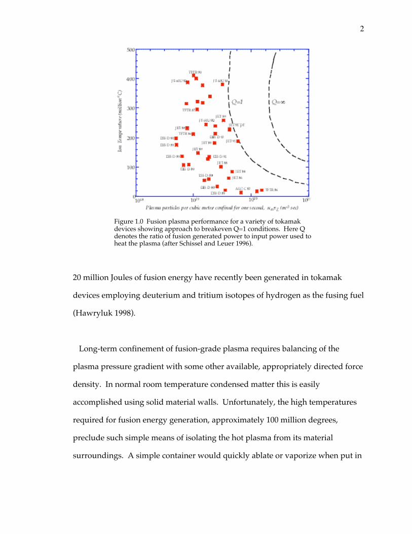
20 million Joules of fusion energy have recently been generated in tokamak
devices employing deuterium and tritium isotopes of hydrogen as the fusing fuel
(Hawryluk 1998).
Long-term confinement of fusion-grade plasma requires balancing of the
plasma pressure gradient with some other available, appropriately directed force
density. In normal room temperature condensed matter this is easily
accomplished using solid material walls. Unfortunately, the high temperatures
required for fusion energy generation, approximately 100 million degrees,
preclude such simple means of isolating the hot plasma from its material
surroundings. A simple container would quickly ablate or vaporize when put in
Figure 1.0 Fusion plasma performance for a variety of tokamakdevices showing approach to breakeven Q=1 conditions. Here Qdenotes the ratio of fusion generated power to input power used toheat the plasma (after Schissel and Leuer 1996).
3
contact with fusion grade plasma. Therefore some other means of holding on to
and isolating the high temperature plasma is necessary.
Presently, the two dominant approaches to maintaining such hot plasma in
equilibrium to generate the required plasma parameters for significant fusion
reactions to occur employ either inertial or magnetic forces to counteract the self-
expansion generated by the confined plasma pressure (Fowler 1999). This thesis
deals with magnetically confined plasma in a tokamak configuration. Externally
generated magnetic perturbations are used to probe tokamak plasma behavior
and the resultant magnetic field and plasma dynamics are then studied. These
external perturbations are generated using a compact saddle coil set designed to
apply a magnetic perturbation that is in resonance with the confining magnetic
field embedded in the HBT-EP tokamak plasma. The response of the plasma-
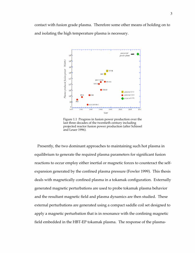
Figure 1.1 Progress in fusion power production over thelast three decades of the twentieth century includingprojected reactor fusion power production (after Schisseland Leuer 1996).
4
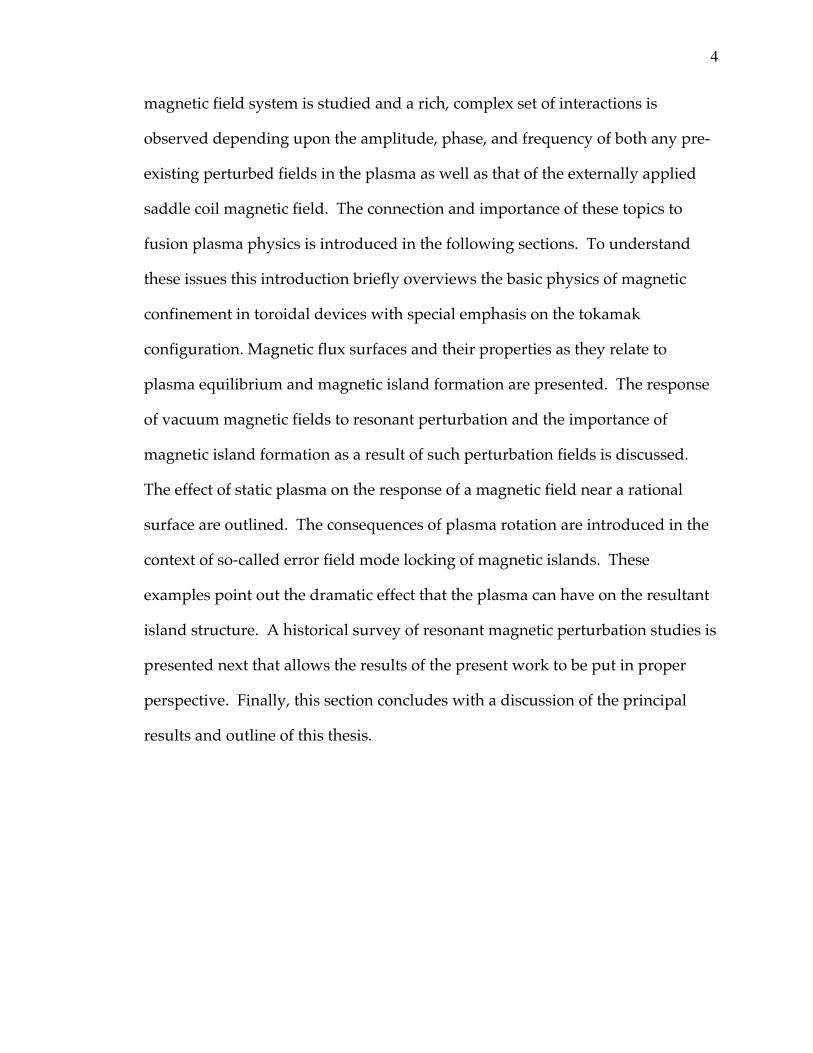
magnetic field system is studied and a rich, complex set of interactions is
observed depending upon the amplitude, phase, and frequency of both any pre-
existing perturbed fields in the plasma as well as that of the externally applied
saddle coil magnetic field. The connection and importance of these topics to
fusion plasma physics is introduced in the following sections. To understand
these issues this introduction briefly overviews the basic physics of magnetic
confinement in toroidal devices with special emphasis on the tokamak
configuration. Magnetic flux surfaces and their properties as they relate to
plasma equilibrium and magnetic island formation are presented. The response
of vacuum magnetic fields to resonant perturbation and the importance of
magnetic island formation as a result of such perturbation fields is discussed.
The effect of static plasma on the response of a magnetic field near a rational
surface are outlined. The consequences of plasma rotation are introduced in the
context of so-called error field mode locking of magnetic islands. These
examples point out the dramatic effect that the plasma can have on the resultant
island structure. A historical survey of resonant magnetic perturbation studies is
presented next that allows the results of the present work to be put in proper
perspective. Finally, this section concludes with a discussion of the principal
results and outline of this thesis.
5
1.1 Fusion plasma
The impetus for much of laboratory plasma physics research has been driven
by the quest for generating man-made fusion energy regime plasma conditions.
The requirements of the fusing fuel dictate the required plasma parameters that
must be achieved in the laboratory. Out of the possible range of most reactive
fusion reactions shown below
1D2 +1T3Æ2He 4+ 0n1 (17.6MeV )
1D2 +1D
2Æ1T3 +1H
1 (4.03MeV)
1D2 +2He 3Æ 2He 4+1H
1 (18.3MeV )
(1.0)
the combination of deuterium and tritium yields the easiest target plasma
parameters. For this reason they are expected to be used in first generation
fusion power sources rather than the other reactions which require higher
temperatures. The conditions for generating fusion power are traditionally
written using the so-called fusion triple product nTtE. Here n is the plasma
density, T the kinetic temperature, and tE is the energy confinement time, defined
as the stored plasma thermal energy divided by the input heating power tE
=WStored/PInput. Using the triple product, the condition for substantial fusion
energy generation from a plasma made up of deuterium and tritium as fuel can
be written as nTtE≥1021 m-3 keV sec (see for example, Wesson 1997). This
condition can be satisfied by a plasma containing n~1020 particles per m3 at a
temperature of T~10keV with a confinement time of tE~1sec. For perspective
recall that 1eV is equivalent to 11,600 degrees Kelvin. Thus, most molecular and
atomic bonds have been broken in a gas heated to 1eV temperature. For fusion
conditions of 100 million degrees the electrons and nuclei that make up the
6
atoms of the fuel have been stripped apart and have been converted into a fully
ionized gas or plasma. Hence the study of plasma physics and its importance to
the fusion enterprise, fusion conditions can only take place in the state of matter
that we call plasma. The basic ideas for confining hot plasma using magnetic
fields or magnetic insulation are discussed next. This sets the stage for a
discussion of magnetic islands and their importance to the nested flux surface
structure used to confine hot plasma.
7
1.2 Magnetic confinement
The magnetic confinement and insulation of plasma is based upon the
magnetic field property that charged particles are channeled along the direction
of the field, limiting their perpendicular excursion. This follows simply from the
resultant charged particle motion given by the Lorentz force rFEM = q(
rE +
rv ¥
rB).
Charged particles are constrained to gyrate perpendicular to the field direction.
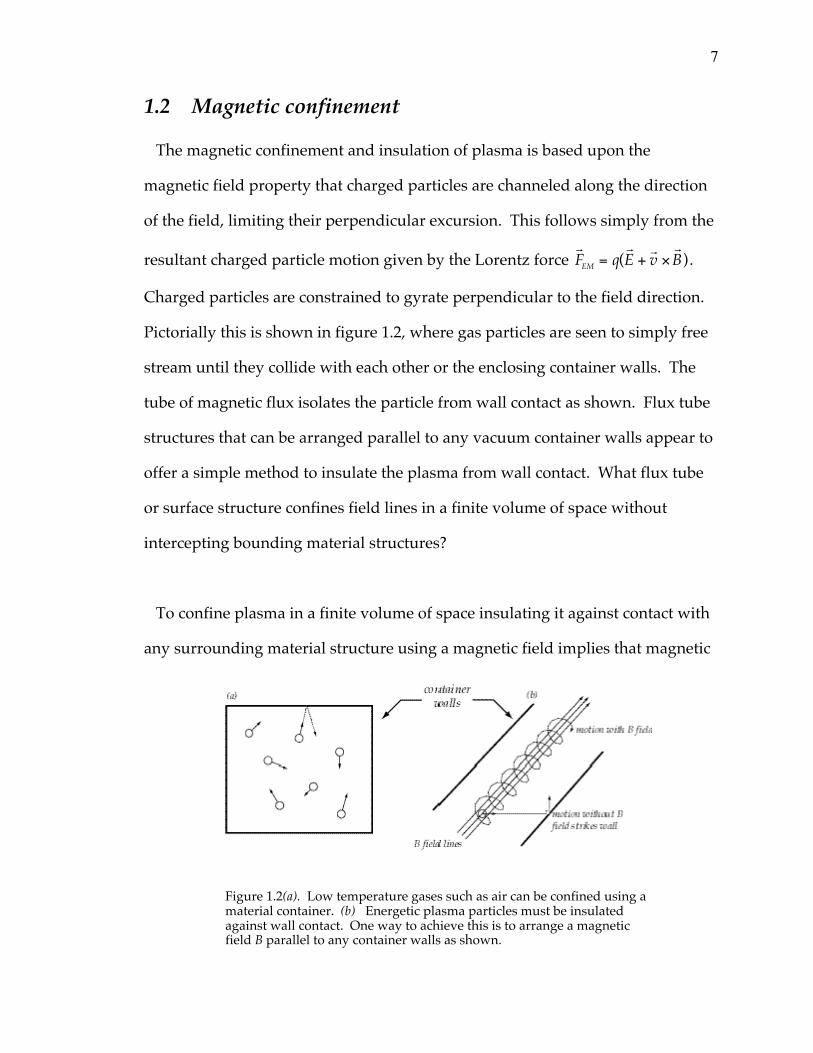
Pictorially this is shown in figure 1.2, where gas particles are seen to simply free
stream until they collide with each other or the enclosing container walls. The
tube of magnetic flux isolates the particle from wall contact as shown. Flux tube
structures that can be arranged parallel to any vacuum container walls appear to
offer a simple method to insulate the plasma from wall contact. What flux tube
or surface structure confines field lines in a finite volume of space without
intercepting bounding material structures?
To confine plasma in a finite volume of space insulating it against contact with
any surrounding material structure using a magnetic field implies that magnetic
Figure 1.2(a). Low temperature gases such as air can be confined using amaterial container. (b) Energetic plasma particles must be insulatedagainst wall contact. One way to achieve this is to arrange a magneticfield B parallel to any container walls as shown.
8
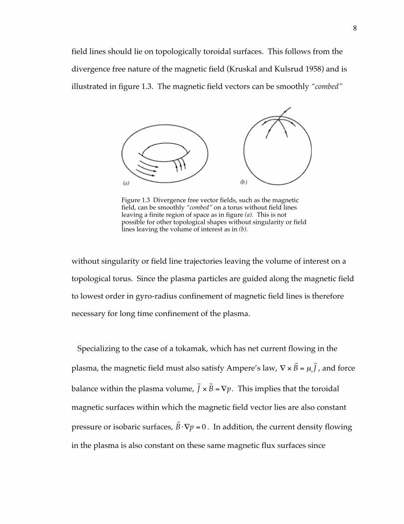
field lines should lie on topologically toroidal surfaces. This follows from the
divergence free nature of the magnetic field (Kruskal and Kulsrud 1958) and is
illustrated in figure 1.3. The magnetic field vectors can be smoothly “combed”
without singularity or field line trajectories leaving the volume of interest on a
topological torus. Since the plasma particles are guided along the magnetic field
to lowest order in gyro-radius confinement of magnetic field lines is therefore
necessary for long time confinement of the plasma.
Specializing to the case of a tokamak, which has net current flowing in the
plasma, the magnetic field must also satisfy Ampere’s law, — ¥rB = mo
rJ , and force
balance within the plasma volume, rJ ¥
rB = —p . This implies that the toroidal
magnetic surfaces within which the magnetic field vector lies are also constant
pressure or isobaric surfaces, rB ⋅—p = 0 . In addition, the current density flowing
in the plasma is also constant on these same magnetic flux surfaces since
Figure 1.3 Divergence free vector fields, such as the magneticfield, can be smoothly “combed” on a torus without field linesleaving a finite region of space as in figure (a). This is notpossible for other topological shapes without singularity or fieldlines leaving the volume of interest as in (b).
9
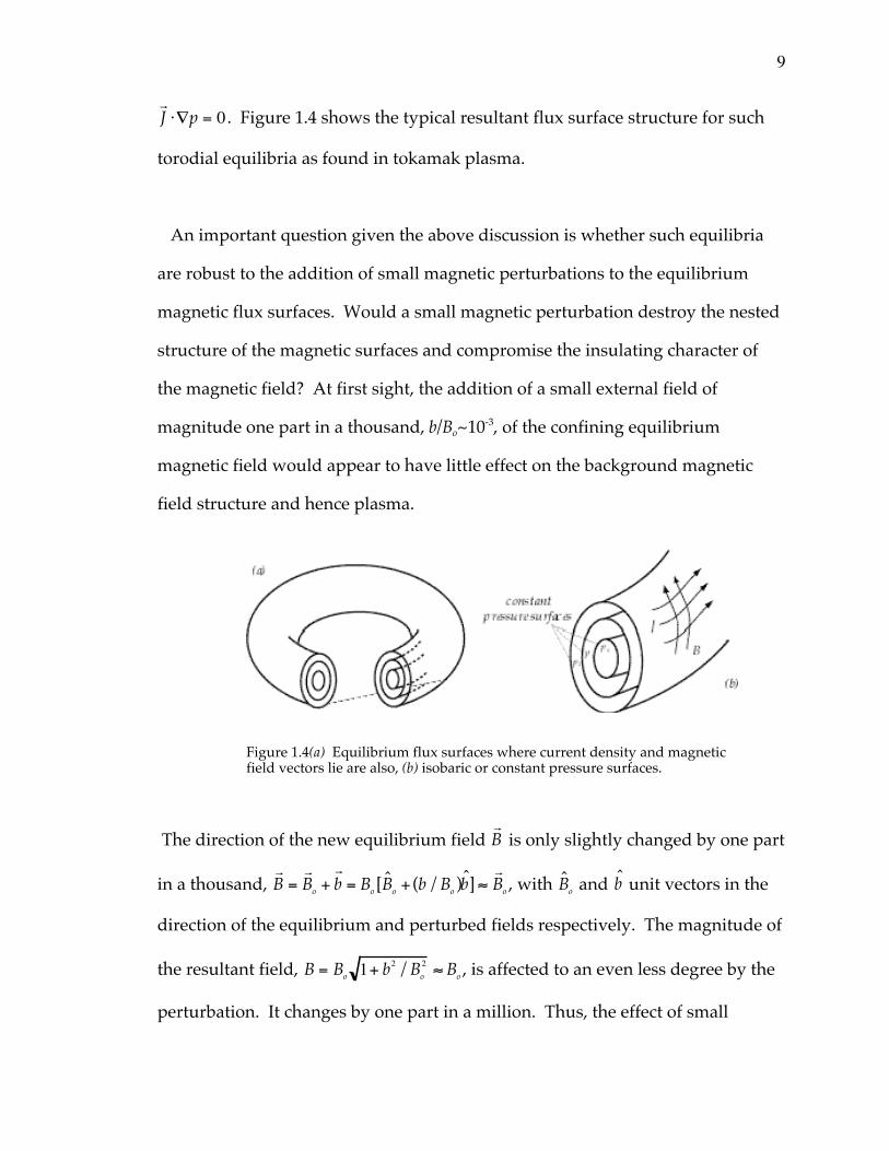
rJ ⋅—p = 0 . Figure 1.4 shows the typical resultant flux surface structure for such
torodial equilibria as found in tokamak plasma.
An important question given the above discussion is whether such equilibria
are robust to the addition of small magnetic perturbations to the equilibrium
magnetic flux surfaces. Would a small magnetic perturbation destroy the nested
structure of the magnetic surfaces and compromise the insulating character of
the magnetic field? At first sight, the addition of a small external field of
magnitude one part in a thousand, b/Bo~10-3, of the confining equilibrium
magnetic field would appear to have little effect on the background magnetic
field structure and hence plasma.
The direction of the new equilibrium field rB is only slightly changed by one part
in a thousand, rB =
rBo +
rb = Bo [Bo + (b/Bo )b] ª
rBo , with Bo and b unit vectors in the
direction of the equilibrium and perturbed fields respectively. The magnitude of
the resultant field, B = Bo 1+ b2 /Bo2 ª Bo , is affected to an even less degree by the
perturbation. It changes by one part in a million. Thus, the effect of small
Figure 1.4(a) Equilibrium flux surfaces where current density and magneticfield vectors lie are also, (b) isobaric or constant pressure surfaces.
10
perturbations to the equilibrium field appears to be essentially negligible.
However, contrary to magnetic perturbation effect on the magnitude and
direction of the combined field at a given point in space such small perturbations
can have a substantial impact on the plasma by changing equilibrium flux
surface structure through a resonance effect. Here the term resonance means
that the helical pitch of the perturbation field match that of the equilibrium
rational surface.
1.3 Magnetic field structure and magnetic islands
Although the direction and magnitude of the equilibrium field are at most only
slightly effected by these small magnetic perturbations, the structure of the
nested flux surfaces containing the plasma can be significantly altered for the
worse (Morozov and Solo ¢v ev 1966). Rather than consider the combined
magnetic field-plasma system response to a magnetic perturbation for this
introduction, the simplified case of vacuum field response is treated first for
clarity. The possible effect of plasma on this vacuum response is then introduced
by considering tearing mode growth in static and rotating plasma in section 1.4.
Consider the effect of a perturbing magnetic field on the flux surface structure
described above. The combined total field is written as rB =
rBo +
rb , with
rb the
perturbation and rBo the equilibrium field. We would like to find new magnetic
surfaces of this total field, that is a function f (rx) such that,
rB ⋅—f = 0 . (1.1)
11
These new magnetic surfaces are then surfaces of constant f. To solve equation
1.1 and ascertain the effect of a small perturbation on flux surface structure
expand f to first order as f=fo+f1, then equation 1.1 yields,
rBo ⋅—fo = 0 , (1.2)
rBo ⋅—f1 +
rb ⋅—fo = 0 . (1.3)
The solution of equation 1.2 is just fo(y) as an arbitrary function of y. Using this
result and the magnetic differential equation for f1, equation 1.3, allows us to
solve for the perturbed surfaces, f=fo+f1. Together they imply that (Boozer 1992),
f1 ~dfo
dybnm(y )
nq(y ) - mexp i(nq - m)( )
n ,m . (1.4)
The use of the term resonance should now be clear given the denominator nq(y)-
m of equation 1.4 for the perturbed part of the flux function f1. When the
perturbation helix matches that of the equilibrium rational magnetic surface
q(y)=m/n at that y surface the denominator in 1.4 vanishes leading to f1 Æ • .
This is the resonance alluded to previously. The resolution of this singularity in
the vacuum magnetic field response to resonant magnetic perturbations is
elegantly understood by noting that the magnetic field constitutes a Hamiltonian
system because of its divergence free character, — ⋅rB = 0 .
The Hamiltonian nature of two-dimensional divergence free vector fields is
well known from fluid dynamics, — ⋅rv = 0 . To see the Hamiltonian nature of this
incompressible two-dimensional vector field introduce a velocity potential such
thatrv = z ¥ —f . Then the streamlines or integral curves of the velocity field of
the system are given by dx/ dt = ∂f /∂y and dy/ dt = -∂f/∂x , which are
12
Hamilton’s equations with the velocity potential f acting as the Hamiltonian of
the system and the Cartesian coordinates acting as the canonical coordinate and
conjugate momentum (Tabor 1996). The fact that fully three-dimensional
divergence free vector fields are also Hamiltonian is not obvious and requires
more subtle treatment (Boozer 1982, Cary and Littlejohn 1983).
In the three dimensional magnetic field case the introduction of a vector
potential of the form rA = j—q + c—f + —f guarantees the Hamiltonian nature of
the problem (Boozer 1992) albeit at the
cost of introducing four potential
functions y ,q ,f, and c . Calculating the
magnetic field from rA in the usual way
yields,rB = —¥
rA = —y ¥—q + —f ¥ —c .
Physically, the potentials are interpreted
as the toroidal magnetic flux y , the
poloidal magnetic flux c , and toroidal
and poloidal angles f and q . The
Hamiltonian equations for what are now
magnetic field lines can be written as,
dy dj = ∂c/∂q , (1.2)
dq dj = -∂c ∂y , (1.3)
with the poloidal flux function the
magnetic field line Hamiltonian. Recognizing this fact then allows us to invoke
the generic Hamiltonian response that rational surfaces under resonant
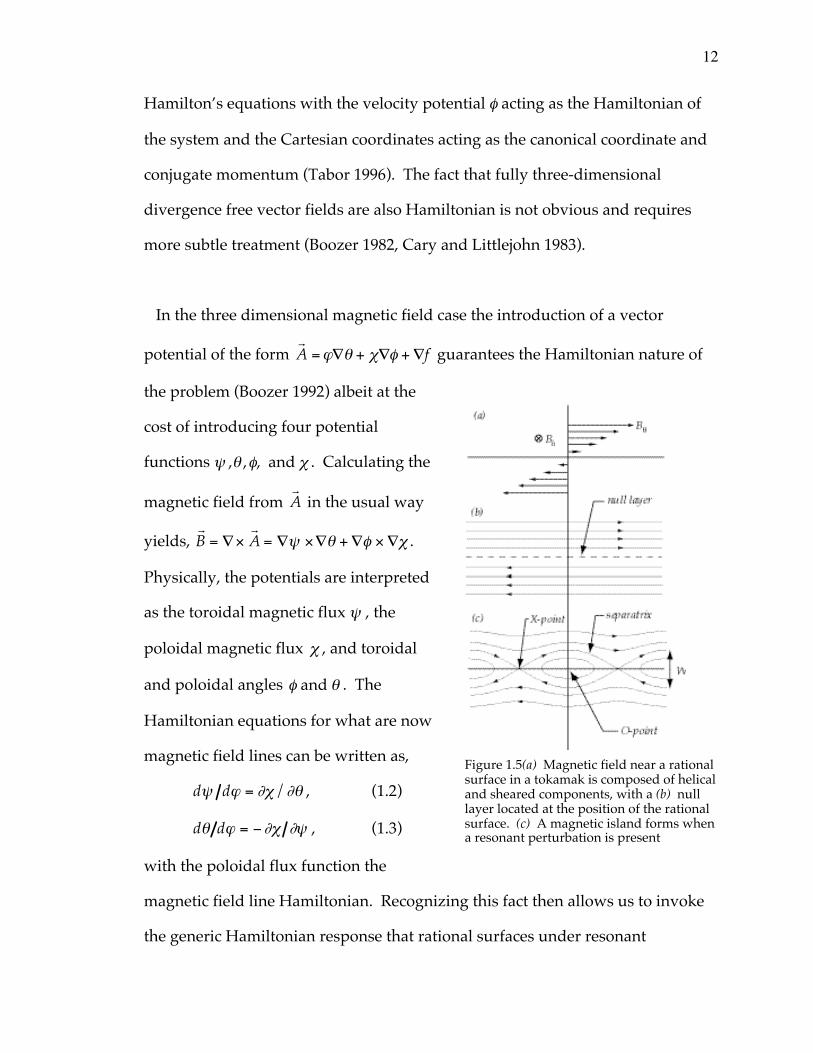
Figure 1.5(a) Magnetic field near a rationalsurface in a tokamak is composed of helicaland sheared components, with a (b) nulllayer located at the position of the rationalsurface. (c) A magnetic island forms whena resonant perturbation is present
13
perturbation break up into phase space island chains (Lichtenberg and
Lieberman 1992). In the magnetic field case these phase space islands are
magnetic islands in three-dimensional physical space.
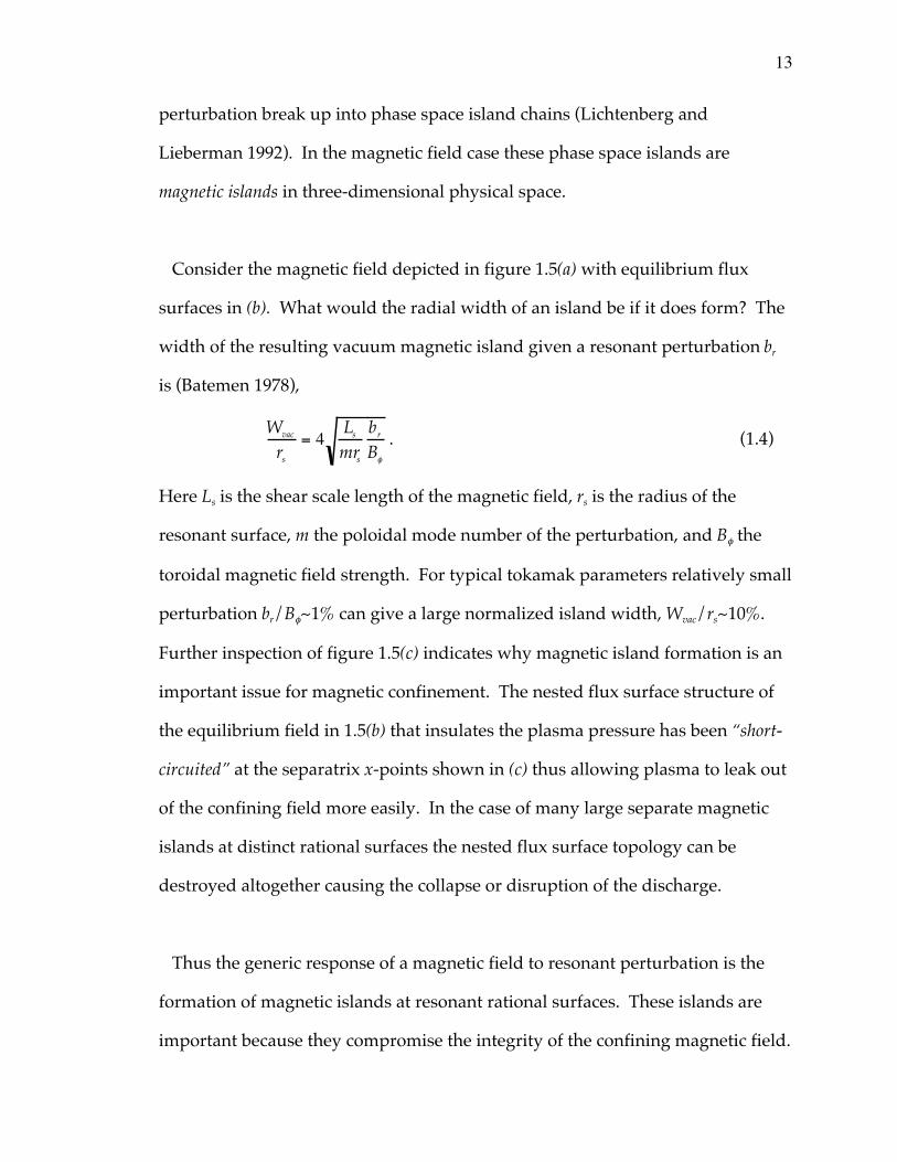
Consider the magnetic field depicted in figure 1.5(a) with equilibrium flux
surfaces in (b). What would the radial width of an island be if it does form? The
width of the resulting vacuum magnetic island given a resonant perturbation br
is (Batemen 1978),
Wvac
rs
= 4 Ls
mrs
br
Bf
. (1.4)
Here Ls is the shear scale length of the magnetic field, rs is the radius of the
resonant surface, m the poloidal mode number of the perturbation, and Bf the
toroidal magnetic field strength. For typical tokamak parameters relatively small
perturbation br/Bf~1% can give a large normalized island width, Wvac/rs~10%.
Further inspection of figure 1.5(c) indicates why magnetic island formation is an
important issue for magnetic confinement. The nested flux surface structure of
the equilibrium field in 1.5(b) that insulates the plasma pressure has been “short-
circuited” at the separatrix x-points shown in (c) thus allowing plasma to leak out
of the confining field more easily. In the case of many large separate magnetic
islands at distinct rational surfaces the nested flux surface topology can be
destroyed altogether causing the collapse or disruption of the discharge.
Thus the generic response of a magnetic field to resonant perturbation is the
formation of magnetic islands at resonant rational surfaces. These islands are
important because they compromise the integrity of the confining magnetic field.
14
An interesting question to now consider is what happens when the magnetic
field is embedded in conducting plasma? This complicates the dynamic response
of the magnetic surface to resonant perturbations considerably. The presence of
plasma near the resonant surface can inhibit or amplify the natural response of
the magnetic field. The plasma conductivity allows local currents to flow near
the rational surface that can lead to healing of the magnetic island or
amplification of island size relative to the vacuum field response given by
equation 1.4.
1.4 Plasma response and magnetic island formation
The natural response of vacuum magnetic fields to resonant perturbation is the
opening of a magnetic island at the resonant rational surface. Near a rational
surface embedded in plasma how is this vacuum response modified? This is the
problem of magnetic reconnection and is germane to many areas of physics from
solar flare to magneto-tail activity as well as magnetic island formation and
disruptive processes in laboratory plasma.
In an ideal plasma with zero electrical resistivity magnetic field evolution is
driven only by plasma flow, since ∂rB/∂t = — ¥ (
rv ¥
rB). This fact is typically stated
saying the magnetic field is frozen to the plasma (Friedberg 1987). This frozen
flux relation implies that magnetic flux through an arbitrary surface that moves
with the plasma fluid is constant, that is, the topology of the magnetic surfaces
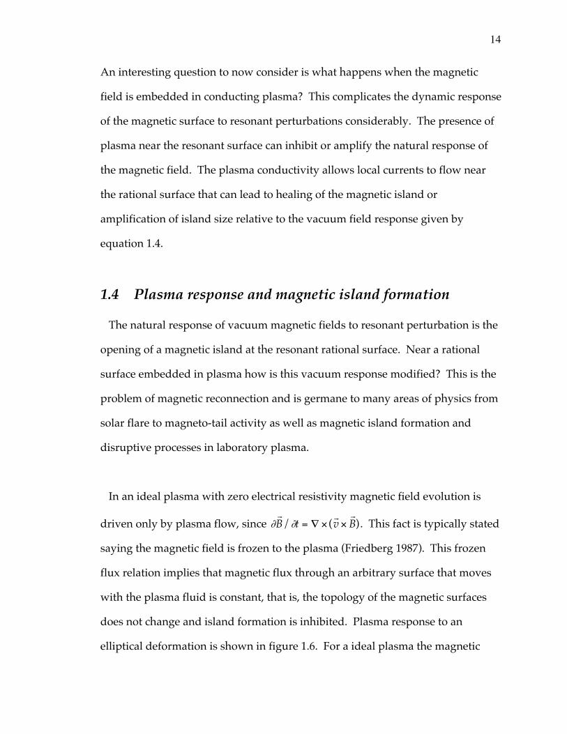
does not change and island formation is inhibited. Plasma response to an
elliptical deformation is shown in figure 1.6. For a ideal plasma the magnetic
15
surfaces merely displace from the circular equilibrium as depicted in figure
1.6(b). How does this response change in weakly non-ideal plasma with finite
resistivity?
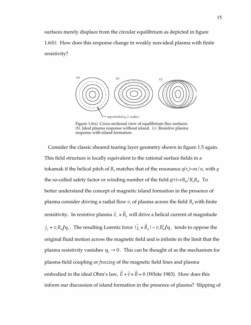
Consider the classic sheared tearing layer geometry shown in figure 1.5 again.
This field structure is locally equivalent to the rational surface fields in a
tokamak if the helical pitch of Bh matches that of the resonance q(rs)=m/n, with q
the so-called safety factor or winding number of the field q(r)=rBf/RoBq. To
better understand the concept of magnetic island formation in the presence of
plasma consider driving a radial flow vr of plasma across the field BJ with finite
resisitivity. In resistive plasma rvr ¥
rBJ will drive a helical current of magnitude
jh = vrBJ h// . The resulting Lorentz force |rjh ¥
rBJ |~ vrBJ
2 h// tends to oppose the
original fluid motion across the magnetic field and is infinite in the limit that the
plasma resistivity vanishes h// Æ 0 . This can be thought of as the mechanism for
plasma-field coupling or freezing of the magnetic field lines and plasma
embodied in the ideal Ohm’s law, rE +
rv ¥
rB = 0 (White 1983). How does this
inform our discussion of island formation in the presence of plasma? Slipping of
Figure 1.6(a). Cross-sectional view of equilibrium flux surfaces.(b). Ideal plasma response without island. (c). Resistive plasmaresponse with island formation.
16
the plasma through the field and hence reconnection of the field can take place at
the null layer centered on the resonant surface. Since BJ vanishes at the
resonance even in the presence of small resistivity the restoring Lorentz force
also vanishes and hence rapid diffusion, reconnection, and magnetic island
formation are still possible in a narrow resistive boundary layer about the
rational surface (Furth et al 1962).
The preceding discussion assumed that plasma away from the rational surface
was at rest. If the plasma is in motion or other driving forces are present the
reconnection rate will be affected as well as the resultant island width. As an
example of the effects of rotation and other external driving forces and how they
might change the vacuum island width consider the case of a magnetic island
driven by a static external source in a tearing stable rotating plasma.
This is the problem of error field driven reconnection of magnetic islands
(Hender et al 1993, La Haye 1994). How does the island width change from its
vacuum value in resistive rotating plasma? In this case the resultant normalized
island width can be written as (for an overview see La Haye 1996),
Wrs
=Wvac
rs
2m- ¢D rs
Ê
ËÁ ˆ
¯˜1/2
11 + wtrec( )2
Ê
ËÁ
ˆ
¯˜
1/4
. (1.5)
The first term on the right hand side is the normalized vacuum island width
Wvac/rs of equation 1.4. The next two factors describe effects of the plasma as a
current carrying medium rotating with respect to the static magnetic
perturbation. The second factor in equation 1.5 gives the effect of the plasma
17
helical current response at the rational surface. Here ¢D is a measure of the
magnetic free energy associated with the stable tearing mode, ¢D < 0 . As
marginal stability is approached, ¢D Æ 0 , the plasma amplifies island size over its
vacuum value, W/Wvac>>1. The third and final term parameterizes the effect of
differential rotation of magnitude w between the rational surface where the
island will form and the exterior stationary perturbation driving the island. Here
trec is the boundary layer reconnection time scale at the rational surface. Thus,
plasma rotation relative to the perturbation can also have a substantial impact on
island width. If the rational surface rotates quickly compared to the
characteristic time scale for flux reconnection, wtrec>>1, the driven island is
highly attenuated with W/Wvac<<1. If the island is frequency locked to the
stationary perturbation w Æ 0 then the vacuum island can again be amplified
due to the ¢D helical current response as described above.
The effect of plasma on the resulting island structure, given the simple
examples above, can be quite profound. Magnetic islands can be either
amplified, shielded from the equilibrium, or take on an intermediate width
depending upon the exact parameters describing the plasma near and far away
from the resonance. In general, the algebraic formula of equations 1.4 and 1.5
that were used to introduce and motivate magnetic island formation and the
possible effects of plasma resistivity, rotation, and external free energy drive are
to simplistic to capture magnetic island dynamical behavior. Instead we deal
with evolution equations for the island width W and island rotation frequency w.
Island rotation frequency is described by a torque balance equation reflecting the
18
effects of plasma inertia, viscosity, and applied saddle coil electromagnetic
torque of the form,
a∂w∂t
= b w -w0( ) +g sin Df( ) . (1.6)
The acceleration term on the left-hand side of 1.6 represents the inertia that co-
rotates with the island while the terms on the right represent the effects of
plasma viscous and saddle coil torque. This island torque balance equation is
studied in section 4.2.1 and compared with HBT-EP island frequency dynamics
during rotation control experiments. Magnetic island width evolution is
governed by a similar equation that reflects any driving sources of free energy
that affect island size,
∂W∂t
~ free energy sources or sinks( ) ~ ¢D (W ,w , Df , ...) . (1.7)
Traditionally, these are referred to as “delta prime” contributions, ¢D , and can be
a function of island amplitude, frequency, phase difference with other external
perturbations or islands within the plasma among others, as indicated in
equation 1.7. For HBT-EP islands the important terms are,
m o
1.2h∂W∂t
= ¢Do 1 -W
Wsat
Ê
ËÁ ˆ
¯˜ +d cos Df( ) + l
w - wo( )2
W 3 (1.8)
Here changes in island width are driven by the three terms on the right–side of
equation 1.8. The first represents the natural instability drive of the current
profile, while the second and third represent the effects of the saddle coil and
plasma inertia on island size. Magnetic island amplitude dynamics during active
rotation control experiments are studied in section 4.3 of this thesis.
19
1.5 Resonant magnetic perturbation research
Magnetic perturbations have been applied to toroidal plasmas for several
decades. This experimental program has predominantly been carried out on
tokamak devices in the past, although recent experimental work has been also
done on reverse field pinch (Den Hartog et al 1994) and stellarator (Knowlton et
al 1997) plasmas as well. These perturbing magnetic fields have been employed
for varying purposes in order to control and study magnetic island behavior.
Active feedback control of magnetic island width has been studied (Bol et al 1974,
Arsenin et al 1975, Navratil et al 1998) and discharge enhancement has been
observed (Morris et al 1990). Magnetic island suppression and asynchronous
disruption avoidance employing static perturbations (Karger et al 1974, Yoshida
et al 1983, Zhao et al 1985) have stabilized small amplitude islands and extended
discharge lifetime under certain plasma conditions. Externally generated
perturbations have also been used to stimulate or induce disruptions and study
the resulting disruption evolution (Bagdasarov et al 1893, Roberts et al 1991, Ivers
et al 1995). Generation of an ergodic magnetic limiter or divertor at the plasma
boundary using static magnetic perturbations as a means of edge particle and
power exhaust control have been examined (Vallet et al 1991, McCool et al 1989),
and are being currently being revisited employing rotating control fields (Finken
1999). Penetration of resonant error fields have been studied extensively using
static perturbations during the last decade (Scoville et al 1991, Hender et al 1992)
in order to understand the operational limits imposed by these locked non-
rotating magnetic islands. To put the research of this thesis in proper
perspective, given the broad application of magnetic perturbations outlined
20
above, a survey of resonant magnetic perturbation research is presented
focussing on the specific application of asynchronous rotating control fields and
their interaction with long wavelength magnetohydrodynamic modes.
Broadly speaking, magnetic perturbation experiments can be divided into those
that actively detect the magnetohydrodynamic mode of interest in real time and
use this signal to derive an appropriate response perturbation and those that
apply a given control field independent of the plasma magnetic island behavior.
These two categories are termed synchronous (closed loop) and asynchronous
(open loop) island or mode control respectively. The work of this thesis deals only
with open loop applied control perturbation signals. Details of the HBT-EP
control coil geometry and driving electronics are discussed in chapter four.
Rotating resonant perturbations were first applied to toroidal plasmas in
experiments on the ATC device at Princeton (Bol et al 1975) and the TO-1
tokamak at the Kurchatov Institute (Arsenin et al 1978). Measured external
magnetic field fluctuations were interpreted as magnetic islands at the m/n=2/1
surface. Frequency locking of these pre-existing fluctuations to applied magnetic
perturbations was reported on both devices. Effects of island growth or
suppression due to the driven deviation in island frequency from the applied
field were not noted. Island frequency locking to the external control
perturbation was later treated theoretically (Invanov and Arsenin 1978) by
invoking a nonlinear oscillator model of the island-coil interaction. Frequency
locking of the pre-existing island was then interpreted as the entrainment of one
oscillator (the island) to that of the driving oscillator (magnetic perturbation).
21
Rotating magnetic perturbations were applied to magnetic fluctuations in the
JFT-2M tokamak (Oasa 1995). Measurement of impurity Carbon rotation using a
neutral beam for spatial localization during these experiments showed an
essentially rigid shift of the Carbon flow profile across the entire plasma minor
radius. Possible reasons for the absence of a more localized interaction near the
dominant rational surface (m/n=2/1 in this case) are not advanced. After
switching off of the stirring perturbation, relaxation of island rotation back to its
equilibrium value observed to be characterized by two time scales. A fast
relaxation occurs first, tfast~ several hundred mircoseconds, and is thought to be
due to rearrangement of the island structure itself. The second characteristic
time is thought to be due to viscous relaxation, tslow~ several milliseconds. No
effects of island amplitude during these magnetic perturbation experiments were
reported.
The experiments on active rotation of magnetic islands on HBT-EP have
demonstrated a simple compact coil technique whose coverage is consistent with
passive wall stabilization requirements. These experiments have extended the
frequency and angular acceleration range and frequency modulation
characteristics used in previous island rotation experiments. This has lead to the
observation of an asymmetry in the damping and growth of island size due to
island frequency changes induced by applied saddle coil torque. This observed
asymmetric response is consistent with a destabilizing contribution to the island
width evolution equation.
22
1.6 Principal results and thesis outline
Using the flexible mode control system developed on the HBT-EP tokamak
(Navratil et al 1998) for magnetic island studies the experiments reported on in
this thesis have demonstrated new methods for interacting and studying the
behavior of magnetic islands in tokamak plasma.
Rotational control of magnetic islands has been demonstrated over an
approximate factor of two change in island frequency using a simple
highly modular saddle coil set. A detailed investigation of the toroidal and
poloidal torque balance near the m/n=2/1 magnetic island has been conducted
to better understand island-perturbation interaction physics. It is found that the
order of magnitude of the applied saddle coil torque needed to induce a given
frequency change in HBT-EP islands is consistent with toroidally driven island
motion. This observation supports the inclusion of poloidal flow damping
physics for magnetic islands in the collisional edge plasma of HBT-EP.
Experimental observation of induced m/n=1/1 mode frequency change during
m/n=2/1 island rotation control indicates that the two islands rotate as a coupled
magnetic structure regardless of external magnetic stirring.
Magnetic island amplitude effects are also observed during active rotation
control experiments. Observation of a correlation between damping and island
deceleration below its natural rotation rate and growth of island amplitude or
width with acceleration during fast rotational change driven by the saddle coil
electromagnetic torque has been demonstrated. This amplitude response is
23
consistent with simple estimates of the magnitude of ion polarization currents
driven by these fast changes in island rotation, including the effects of poloidal
flow damping. The observed asymmetry in growth and damping with
acceleration and deceleration of these magnetic islands is consistent with a
destabilizing inertial contribution to the island width evolution equation of
motion. This observation constitutes the first experimental evidence for the
destabilizing role of ion inertia in magnetic island dynamics. Finally, using an
applied saddle coil perturbation of this type it has been demonstrated for the first
time that the severity of disruptions is greatly diminished by applying this
frequency modulated control field. When applied to disruptive plasmas core
thermal and particle loss is inhibited due to maintenance of outer flux surface
integrity.
Preliminary to discussing the frequency and amplitude behavior of HBT-EP
magnetic islands a brief machine description of the HBT-EP tokamak, its
magnetic island control system, and a brief resume of basic diagnostics is given
in chapter two. Chapter three develops the necessary analysis tools used to
study magnetic island behavior for this thesis. A more detailed discussion is
given of those measurements used to quantify island response of both the
m/n=2/1 and 1/1 islands. This includes an equilibrium current profile
estimated using soft x-ray measurements to locate positions of rational surfaces
within the plasma volume. Chapter four contains the main results of the
frequency and amplitude behavior of islands under the action of applied rotating
magnetic perturbations. Here the measured torque balance near a large
amplitude HBT-EP magnetic island is developed. A description of the torque
24
balance model is given along with experimentally measured locking torque
estimates. Chapter four also summarizes the observed frequency dependent
amplitude growth and damping observed of HBT-EP magnetic islands induced
by changing island rotation away from its natural rate by the applied saddle coil
control fields. Estimates of the effect of inertia for HBT-EP islands is discussed in
detail, and the asymmetric response observed is shown to be consistent with a
destabilizing delta prime contribution to the island evolution equation. These
perturbations are then applied to disruptive target plasma and found to inhibit
core thermal and particle loss. Chapter five concludes this thesis with a
summary of island control dynamics and thoughts for future work.
25
2.0 HBT-EP machine description
The High Beta Tokamak-Extended Pulse (HBT-EP) was designed and built to
study active and passive control techniques applicable to long wavelength
magnetohydrodynamic instabilities (Mauel et al 1991, Sankar et al 1993). In order
to ameliorate the unwanted effect of these plasma performance limiting
magnetohydrodynamic modes, the HBT-EP program has concentrated on
demonstrating passive wall stabilization of ideal kink-type instabilities and
active control of resistive tearing modes employing an external coil set able to
generate resonant magnetic perturbations. This chapter briefly describes the
HBT-EP tokamak, plasma formation, and basic diagnostic set used to conduct the
research of this thesis. A brief summary of past HBT-EP mode control research is
given next as an introduction to the machine description.
Initial studies of high bN driven global kink–type modes and edge current
gradient driven kinks demonstrated passive wall stabilization of these modes
with reduced mode amplitude and extended discharge lifetime (Gates 1993, Ivers
et al 1995). Here the normalized plasma b is defined as,
bN ≡b
Ip / aBf
, (2.0)
with the ratio of plasma energy density to confining magnetic field energy
density, or traditional plasma b given by,
b ≡(1/Vp ) pdVÚ
B2 /2mo
. (2.1)
26
Here p is the kinetic pressure of the plasma, B is the magnetic field strength and
Vp is the plasma volume under consideration. For b measured in percent, the
plasma current Ip in mega-Amperes, plasma minor radius a in meters, and the
toroidal field strength on the machine axis Bf in Tesla, equation 2.0 above gives
bN ~ 1 to 2 for typical HBT-EP operating parameters. In a fusion context,
maximizing b is important since fusion power production scales as the plasma b
squared, Pfusion~b2. These early HBT-EP experiments correlated the suppression
of kink instability occurrence, lengthened discharge lifetime, and higher
operational bN performance critical to economical fusion energy production
when the movable conducting wall segments were inserted near the plasma
surface for maximum passive stabilization.
Subsequent wall stabilization work elucidated wall influence on disruption
dynamics (Kombargi 1997), compared experimental measurements of
equilibrium and stability of wall stabilized discharges with ideal MHD
computational modeling (Garofalo 1997, Garofalo et al 1998), and measured the
effects of segmented wall symmetry and coverage on kink mode suppression
(Eisner 1998). With these quickly growing modes wall stabilized attention
focussed on residual instabilities that affected plasma behavior. In order to deal
with these more slowly growing instabilities not effected by a close conducting
boundary, an active means of interacting with these internal instabilities was
developed on the HBT-EP tokamak. This active control system uses an external
coil set designed to generate an applied field in resonance with the equilibrium
magnetic field line pitch of the dominant m/n=2/1 internal instabilities observed
27
on HBT-EP. These modes manifest themselves as a magnetic island chain in the
edge plasma of HBT-EP.
The first resonant magnetic perturbation experiments to influence m/n=2/1
mode behavior on HBT-EP demonstrated magnetic island braking, locking, and
induced plasma disruption (Ivers et al 1994). A capacitor bank driven
perturbation was used in these early experiments, creating a static non-rotating
applied magnetic field in the laboratory frame of reference. Single-phase
standing wave perturbations were next applied to the coil set and characteristic
island frequency modulation was observed (Mauel et al 1996). Later work
initiated studies of magnetic feedback control of resistive tearing mode
amplitude and frequency employing a rotating magnetic perturbation generated
by a two-phase saddle coil set (Ivers et al 1995, Mauel et al 1998, Navratil et al
1998). Xiao has performed a mode structure analysis of MHD modes during
both passive wall stabilization experiments and active rotation control of
magnetic islands (Xiao 1998). These rotating control magnetic fields have been
used in an extensive study of active, synchronous feedback (Nadle 2000) and its
associated phase instability (Nadle et al 2000). Taylor has investigated the effect
of magnetic islands on local HBT-EP plasma behavior using Mach-Langmuir
probe apparatus (Taylor 2000). These measurements confirmed induced ion flow
change during the rotation control or magnetic stirring of HBT-EP islands.
Current HBT-EP experimental work aims at influencing these long wavelength
magnetohydrodyanmic modes using a hopefully synergistic combination of
passive and active control techniques. The implementation of a so-called “smart”
28
or “intelligent” shell concept has shown promising initial ability to control
resistive wall kink modes (Cates et al 2000). Next, the HBT-EP tokamak and its
basic parameters are discussed as well as the target plasmas developed for the
study of magnetic islands under the action of externally applied rotating
resonant magnetic perturbations.
The HBT-EP tokamak is a high aspect ratio device with several novel features
including a movable conducting segmented wall, quartz insulating vacuum
chamber breaks for fast magnetic field penetration and a flexible saddle coil set
for magnetic island studies. A brief discussion of the equilibrium magnetic field
coil systems, vacuum chamber and pumping system, and basic plasma
diagnostics is given. More detailed discussion of specific diagnostics and their
analysis used in measurement of specific m/n=2/1 and 1/1 magnetic island
characteristics are reserved until chapter three. The details of the saddle coil
system and driving electronics are given in chapter four.
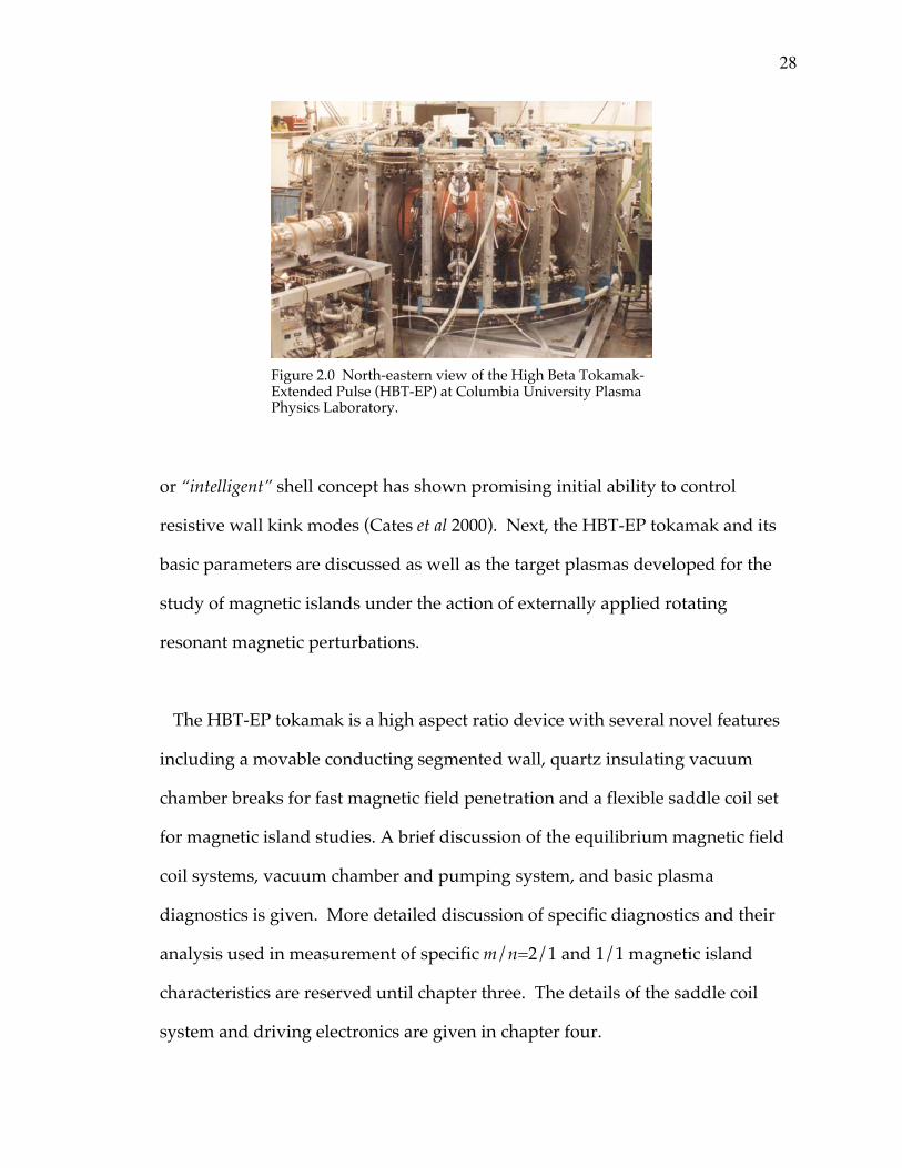
Figure 2.0 North-eastern view of the High Beta Tokamak-Extended Pulse (HBT-EP) at Columbia University PlasmaPhysics Laboratory.
29
The HBT-EP tokamak (see figure 2.0) is
an Ohmically heated device capable of
sustaining positive loop voltage for a
10msec period. Typical discharge
lifetimes range from several milliseconds
to ~7 to 12msec depending upon the
specific operational regime in question.
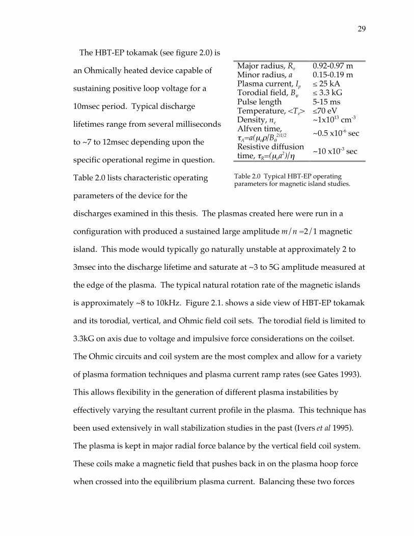
Table 2.0 lists characteristic operating
parameters of the device for the
discharges examined in this thesis. The plasmas created here were run in a
configuration with produced a sustained large amplitude m/n =2/1 magnetic
island. This mode would typically go naturally unstable at approximately 2 to
3msec into the discharge lifetime and saturate at ~3 to 5G amplitude measured at
the edge of the plasma. The typical natural rotation rate of the magnetic islands
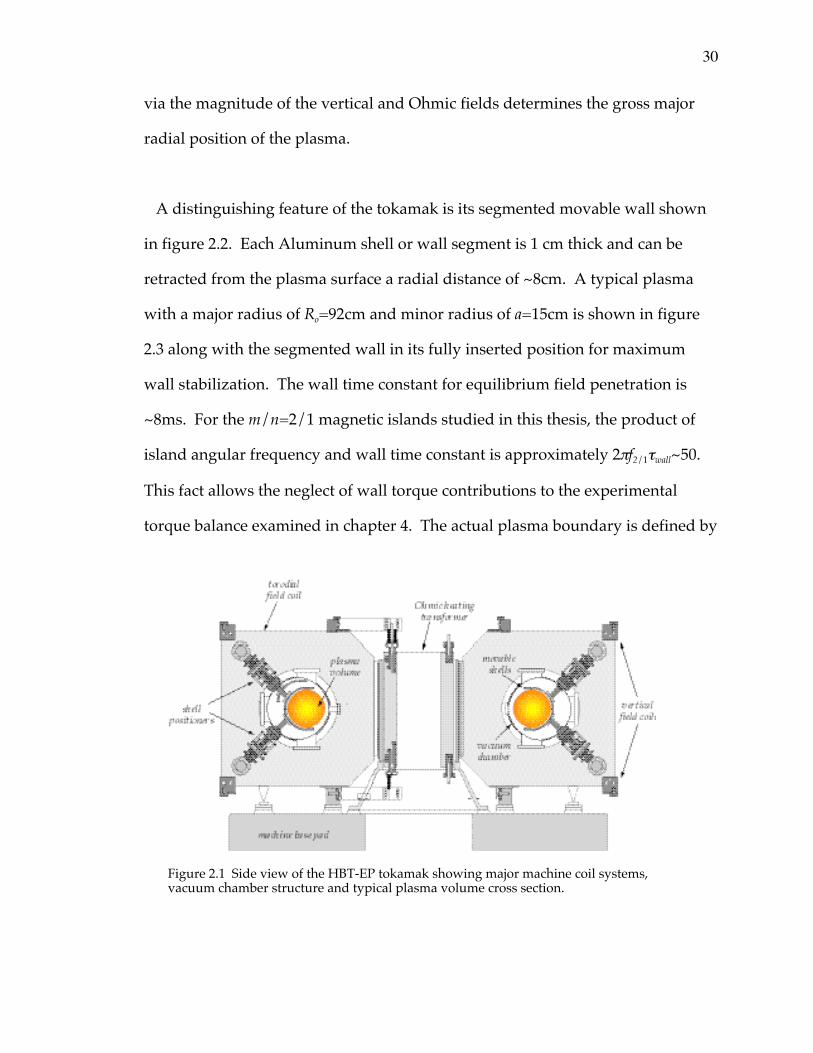
is approximately ~8 to 10kHz. Figure 2.1. shows a side view of HBT-EP tokamak
and its torodial, vertical, and Ohmic field coil sets. The torodial field is limited to
3.3kG on axis due to voltage and impulsive force considerations on the coilset.
The Ohmic circuits and coil system are the most complex and allow for a variety
of plasma formation techniques and plasma current ramp rates (see Gates 1993).
This allows flexibility in the generation of different plasma instabilities by
effectively varying the resultant current profile in the plasma. This technique has
been used extensively in wall stabilization studies in the past (Ivers et al 1995).
The plasma is kept in major radial force balance by the vertical field coil system.
These coils make a magnetic field that pushes back in on the plasma hoop force
when crossed into the equilibrium plasma current. Balancing these two forces
Major radius, Ro 0.92-0.97 mMinor radius, a 0.15-0.19 mPlasma current, Ip ≤ 25 kATorodial field, Bj ≤ 3.3 kGPulse length 5-15 msTemperature, <Te> ≤70 eVDensity, ne ~1x1013 cm-3
Alfven time,tA=a(mor/Bq
2)1/2 ~0.5 x10⁻⁶ sec
Resistive diffusiontime, tR=(moa2)/h ~10 x10-3 sec
Table 2.0 Typical HBT-EP operatingparameters for magnetic island studies.
30
via the magnitude of the vertical and Ohmic fields determines the gross major
radial position of the plasma.
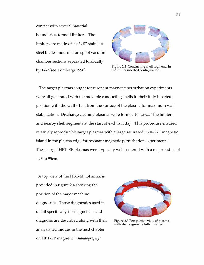
A distinguishing feature of the tokamak is its segmented movable wall shown
in figure 2.2. Each Aluminum shell or wall segment is 1 cm thick and can be
retracted from the plasma surface a radial distance of ~8cm. A typical plasma
with a major radius of Ro=92cm and minor radius of a=15cm is shown in figure
2.3 along with the segmented wall in its fully inserted position for maximum
wall stabilization. The wall time constant for equilibrium field penetration is
~8ms. For the m/n=2/1 magnetic islands studied in this thesis, the product of
island angular frequency and wall time constant is approximately 2pf2/1twall~50.
This fact allows the neglect of wall torque contributions to the experimental
torque balance examined in chapter 4. The actual plasma boundary is defined by
Figure 2.1 Side view of the HBT-EP tokamak showing major machine coil systems,vacuum chamber structure and typical plasma volume cross section.
31
contact with several material
boundaries, termed limiters. The
limiters are made of six 3/8” stainless
steel blades mounted on spool vacuum
chamber sections separated toroidally
by 144o (see Kombargi 1998).
The target plasmas sought for resonant magnetic perturbation experiments
were all generated with the movable conducting shells in their fully inserted
position with the wall ~1cm from the surface of the plasma for maximum wall
stabilization. Discharge cleaning plasmas were formed to “scrub” the limiters
and nearby shell segments at the start of each run day. This procedure ensured
relatively reproducible target plasmas with a large saturated m/n=2/1 magnetic
island in the plasma edge for resonant magnetic perturbation experiments.
These target HBT-EP plasmas were typically well centered with a major radius of
~93 to 95cm.
A top view of the HBT-EP tokamak is
provided in figure 2.4 showing the
position of the major machine
diagnostics. Those diagnostics used in
detail specifically for magnetic island
diagnosis are described along with their
analysis techniques in the next chapter
on HBT-EP magnetic “islandography”
Figure 2.3 Perspective view of plasmawith shell segments fully inserted.
Figure 2.2 Conducting shell segments intheir fully inserted configuration.
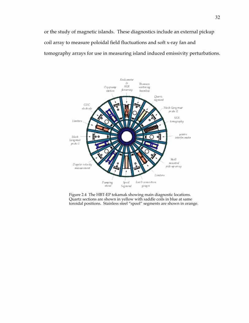
32
or the study of magnetic islands. These diagnostics include an external pickup
coil array to measure poloidal field fluctuations and soft x-ray fan and
tomography arrays for use in measuring island induced emissivity perturbations.
Figure 2.4 The HBT-EP tokamak showing main diagnostic locations.Quartz sections are shown in yellow with saddle coils in blue at sametoroidal positions. Stainless steel “spool” segments are shown in orange.
33
3.0 HBT-EP magnetic islandography
In this chapter we study the properties of long wavelength magnetic
fluctuations observed on the HBT-EP tokamak. These external magnetic
fluctuations are interpreted as arising from a magnetic island chain located on
the resonant q=2 surface inside the plasma. This inference is confirmed by
internal soft x-ray emissivity measurements which show a local phase inversion
layer at the position of the mode rational surface (Xiao 1998). This emissivity
inversion surface is a result of the pre-existing plasma electron density or
temperature profile adjusting to the details of the new magnetic topology
introduced by the island structure. Phase inversion observations are a primary
method for distinguishing between simple flux surface distortion or
displacement which does not change magnetic surface topology and the splitting
or tearing of a surface which does alter the magnetic topology of the
configuration (recall figure 1.6 of the introduction).
First details of the external magnetic analysis used to measure the m=2
component of the fluctuation spectrum is described. The direction of natural
m=2 mode propagation poloidally and in the electron drift direction is shown.
Next, interpretation of soft x-ray emissivity measurements as they relate to
diagnosis of magnetic islands is examined and details of the tomographic and
core fan array detectors are given. The analysis of m/n=2/1 island builds on
previous work of Xiao (1998). These soft x-ray measurements are then used to
give an estimate of the position of the q=2 surface. This is later used to construct
an average current density profile in section 3.4. Spectral quantities of the m=2
34
emissivity fluctuation are constructed using the Hilbert transform technique of
Taylor and coworkers (1999) to confirm corotation of the m=2 emissivity
perturbation and magnetic perturbation. Next the analysis of m/n=1/1 island
emissivity fluctuations is explained. This uses a robust combination of singular
value decomposition (SVD) as advocated by Dudok de Wit (1994) and Hilbert
transformation (Taylor et al 1999) to extract m/n=1/1 mode spectral behavior.
The chapter concludes by pulling these three diagnostic sections together in
constructing an approximate current density and q-profile to estimate magnetic
island widths using the vacuum island width formula discussed in the
introduction.
35
3.1 External magnetic mode analysis
In this section the basic magnetic modal analysis used to diagnosis
m/n=2/1 magnetic islands on HBT-EP is described. The natural island
propagation direction is observed for target plasmas that will later be used in
the rotational control studies presented in chapter four.
An array of inductive pick-up coils located on the inner side of the
conducting shells is used to measure the fluctuating and equilibrium values
of the poloidal magnetic field. These probes have been used extensively in
past experiments to characterize the magnetohydrodynamic behavior of
HBT-EP plasmas (Garofalo 1997). For the purposes of this thesis the
extraction of the fluctuating m=2 component serves as one of the main
indicators of magnetic island behavior, giving a measure of mode amplitude,
phase and frequency. The circular geometry and high aspect ratio of HBT-EP
plasmas minimizes many of the typical difficulties encountered in external
magnetic diagnosis of MHD fluctuations (Hammet and McGuire 1982, Strait
1995). This allows a relatively simple procedure to extract the Fourier
component of interest, in this case m=2. The sin2q and cos2q Fourier
components of the fluctuating magnetic field, h(t) = a(t)sin[2q( t)] and
g(t) = a(t)cos[2q (t)], are derived from the total signal, after equilibrium
subtraction, by a least squares fit to the data using singular value
decomposition. The sin2q and cos2q components are then used to construct
the magnitude and phase of the m=2 fluctuation via,
bq t( ) = h(t)2 + g(t)2 = a(t) (3.0)
36
j(t) = tan -1 h(t)g(t)
Ê
ËÁ ˆ
¯˜ = 2q(t) , (3.1)
f2/1(t) =12p
djdt
. (3.2)
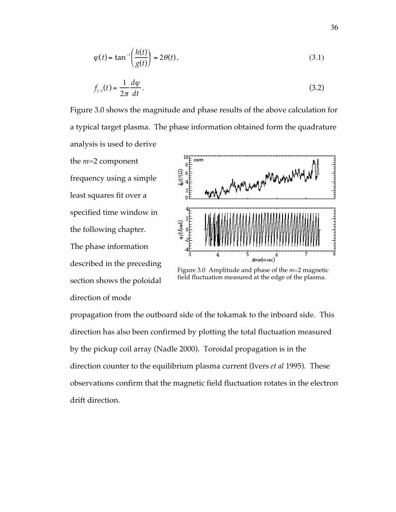
Figure 3.0 shows the magnitude and phase results of the above calculation for
a typical target plasma. The phase information obtained form the quadrature
analysis is used to derive
the m=2 component
frequency using a simple
least squares fit over a
specified time window in
the following chapter.
The phase information
described in the preceding
section shows the poloidal
direction of mode
propagation from the outboard side of the tokamak to the inboard side. This
direction has also been confirmed by plotting the total fluctuation measured
by the pickup coil array (Nadle 2000). Toroidal propagation is in the
direction counter to the equilibrium plasma current (Ivers et al 1995). These
observations confirm that the magnetic field fluctuation rotates in the electron
drift direction.
Figure 3.0 Amplitude and phase of the m=2 magneticfield fluctuation measured at the edge of the plasma.
37
3.2 Emissivity measurements of magnetic islands
3.2.1 An introduction
Here observation of soft x-ray radiation is described that gives an internal
measurement of the m=2 mode structure in the edge region and the m=1 mode in
the core plasma of HBT-EP. These emissivity observations are made using two
complementary arrays of soft x-ray detectors. A sixteen channel fan array
(Kombargi 1997) that resolves core sawtooth oscillation and m=1 mode behavior
and a thirty-two channel tomographic array (Xiao 1998) with good edge
sensitivity for diagnosis of m=2 island induced emissivity fluctuations.
First, the functional form of the emissivity and its relation to plasma
parameters such as temperature and density is briefly reviewed. Unfortunately,
even in a simple approximate form the emissivity is a convolution of several
plasma parameters that can be spatially and temporally varying. In the limit
where the impurity content or average ion charge state in the plasma is low and
the ionic species are not significantly changing in time the emissivity is
predominantly a function of electron temperature and density. Even in the
context of this simplification the chord integrated nature of the emissivity
measurement precludes a simple interpretation of the emissivity fluctuation in
terms of associated local temperature and density fluctuation amplitudes
induced by the magnetic island. After discussion of the m=2 island induced soft
x-ray fluctuations, details and diagnosis of the core m/n=1/1 mode and
associated core emissivity relaxation oscillations or sawteeth are presented.
38
The behavior of the m/n=1/1 mode in the core of HBT-EP discharges is
diagnosed using the fan-array of soft x-ray detectors. To separate sawtooth
activity from 1/1 mode dynamics singular decomposition of the fan-array
channel time series into distinct biorthogonal eigenfunctions is used. These
singular eigenmodes deconvolve the m/n=1/1 mode from the n=0 and m=0
sawtooth rise, crash, and inversion. This deconvolution then allows calculation
of m/n=1/1 mode amplitude, phase, and frequency that is later used in m/n=2/1
magnetic island interaction studies with an external resonant magnetic
perturbation.
This m=2 and m=1 emissivity analysis is also used in section 3.4 to construct an
average current density and q-profiles that are then used in estimation of m=2
magnetic island width calculations. The functional form of the plasma emissivity
and relevant plasma parameter scalings are discussed next.
3.2.2 Emissivity and its relation to plasma parameters
Plasmas emit radiant energy over a broad spectral range from the near infrared
up to photon energies of order the plasma electron temperature (Bekefi 1966).
The HBT-EP tokamak is equipped with two soft x-ray diagnostics that are used
to measure plasma photon emission in the hw ~20 to 150eV energy range. A
sixteen channel fan-array that measures core sawtooth and m/n=1/1 activity and
a thirty-two channel tomography system that is able to resolve emissivity
fluctuations at the m/n=2/1 surface near the plasma edge. The dominant
physical processes leading to this emission are free-free, free-bound, and bound-
39
bound electron-ion interactions termed Bremstrahlung, recombination radiation,
and line radiation respectively. For simplicity only the continuum
(bremstrahlung and recombination) contribution to the emissivity will be
discussed in detail here.
Following the discussion given by Hutchinson (1993), the total continuum
radiation from electron-ion collisions for the ith ionic species can be written as,
ji w( ) = Zi2neni
e2
4peo
Ê
ËÁ ˆ
¯˜3
43 3me
2c32me
pTeexp -
hwTe
Ê
ËÁ ˆ
¯˜
È
Î͢
˚
¥ gff + Gnxn3
c i
Te
Ê
ËÁ ˆ
¯˜ exp
ci
Te
È
Î͢
˚+ Gn
2n
Zi2Ry
n 2Te
Ê
ËÁ
ˆ
¯˜ exp
Zi2Ry
n 2Te
È
Î͢
˚n =n+1
•
ÂÏÌÓ
¸˝˛
. (3.3)
The first term in curly brackets is the free-free contribution and the second and
third terms represent free-bound transitions to the lowest unfilled energy level
and to all other available levels respectively of the given ion. This radiation
results from the electron accelerating and decelerating in the attractive Coulomb
field of the ion in question. If the total energy of the electron-ion system is
positive the electron is merely deflected (free-free transition) by the ion Coulombic
field, while a negative total energy implies the electron is captured (free-bound
transition) and recombines with the ion. Here,
Zi ≡ charge state of the ith ion
ni ≡ number density of the ith ion
gff ≡ free - free Gaunt factor
Gk ≡ free - bound Gaunt factor for kth level
Ry ≡ Rydberg energy =13.6eV
(3.4)
40
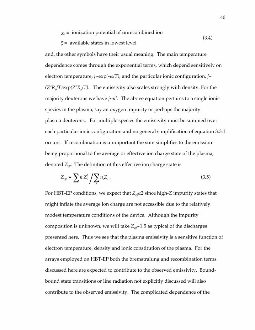
ci ≡ ionization potential of unrecombined ion
x ≡ available states in lowest level(3.4)
and, the other symbols have their usual meaning. The main temperature
dependence comes through the exponential terms, which depend sensitively on
electron temperature, j~exp(-w/T), and the particular ionic configuration, j~
(Z2Ry/T)exp(Z2Ry/T). The emissivity also scales strongly with density. For the
majority deuterons we have j~n2. The above equation pertains to a single ionic
species in the plasma, say an oxygen impurity or perhaps the majority
plasma deuterons. For multiple species the emissivity must be summed over
each particular ionic configuration and no general simplification of equation 3.3.1
occurs. If recombination is unimportant the sum simplifies to the emission
being proportional to the average or effective ion charge state of the plasma,
denoted Zeff. The definition of this effective ion charge state is
Zeff ≡ niZi2
i niZi
i . (3.5)
For HBT-EP conditions, we expect that Zeff≤2 since high-Z impurity states that
might inflate the average ion charge are not accessible due to the relatively
modest temperature conditions of the device. Although the impurity
composition is unknown, we will take Zeff~1.5 as typical of the discharges
presented here. Thus we see that the plasma emissivity is a sensitive function of
electron temperature, density and ionic constitution of the plasma. For the
arrays employed on HBT-EP both the bremstralung and recombination terms
discussed here are expected to contribute to the observed emissivity. Bound-
bound state transitions or line radiation not explicitly discussed will also
contribute to the observed emissivity. The complicated dependence of the
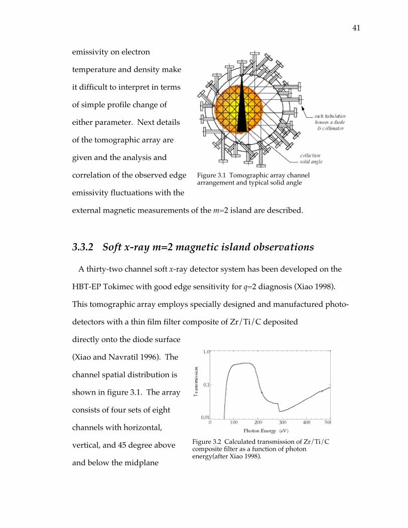
41
emissivity on electron
temperature and density make
it difficult to interpret in terms
of simple profile change of
either parameter. Next details
of the tomographic array are
given and the analysis and
correlation of the observed edge
emissivity fluctuations with the
external magnetic measurements of the m=2 island are described.
3.3.2 Soft x-ray m=2 magnetic island observations
A thirty-two channel soft x-ray detector system has been developed on the
HBT-EP Tokimec with good edge sensitivity for q=2 diagnosis (Xiao 1998).
This tomographic array employs specially designed and manufactured photo-
detectors with a thin film filter composite of Zr/Ti/C deposited
directly onto the diode surface
(Xiao and Navratil 1996). The
channel spatial distribution is
shown in figure 3.1. The array
consists of four sets of eight
channels with horizontal,
vertical, and 45 degree above
and below the midplane
Figure 3.1 Tomographic array channelarrangement and typical solid angle
Figure 3.2 Calculated transmission of Zr/Ti/Ccomposite filter as a function of photonenergy(after Xiao 1998).
42
views. Chordal spacing for each of the eight channel sets is 4 cm. The typical
channel width mapped to the midplane of the tokamak is approximately ~4cm.
The calculated transmission for the composite filter is shown in figure 3.2.
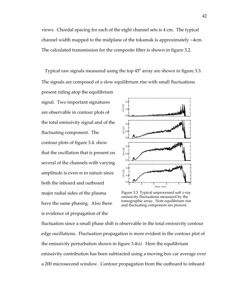
Typical raw signals measured using the top 45o array are shown in figure 3.3.
The signals are composed of a slow equilibrium rise with small fluctuations
present riding atop the equilibrium
signal. Two important signatures
are observable in contour plots of
the total emissivity signal and of the
fluctuating component. The
contour plots of figure 3.4. show
that the oscillation that is present on
several of the channels with varying
amplitude is even-m in nature since
both the inboard and outboard
major radial sides of the plasma
have the same phasing. Also there
is evidence of propagation of the
fluctuation since a small phase shift is observable in the total emissivity contour
edge oscillations. Fluctuation propagation is more evident in the contour plot of
the emissivity perturbation shown in figure 3.4(a). Here the equilibrium
emissivity contribution has been subtracted using a moving box car average over
a 200 microsecond window. Contour propagation from the outboard to inboard
Figure 3.3 Typical unprocessed soft x-rayemissivity fluctuations measured by thetomographic array. Note equilibrium riseand fluctuating component are present.
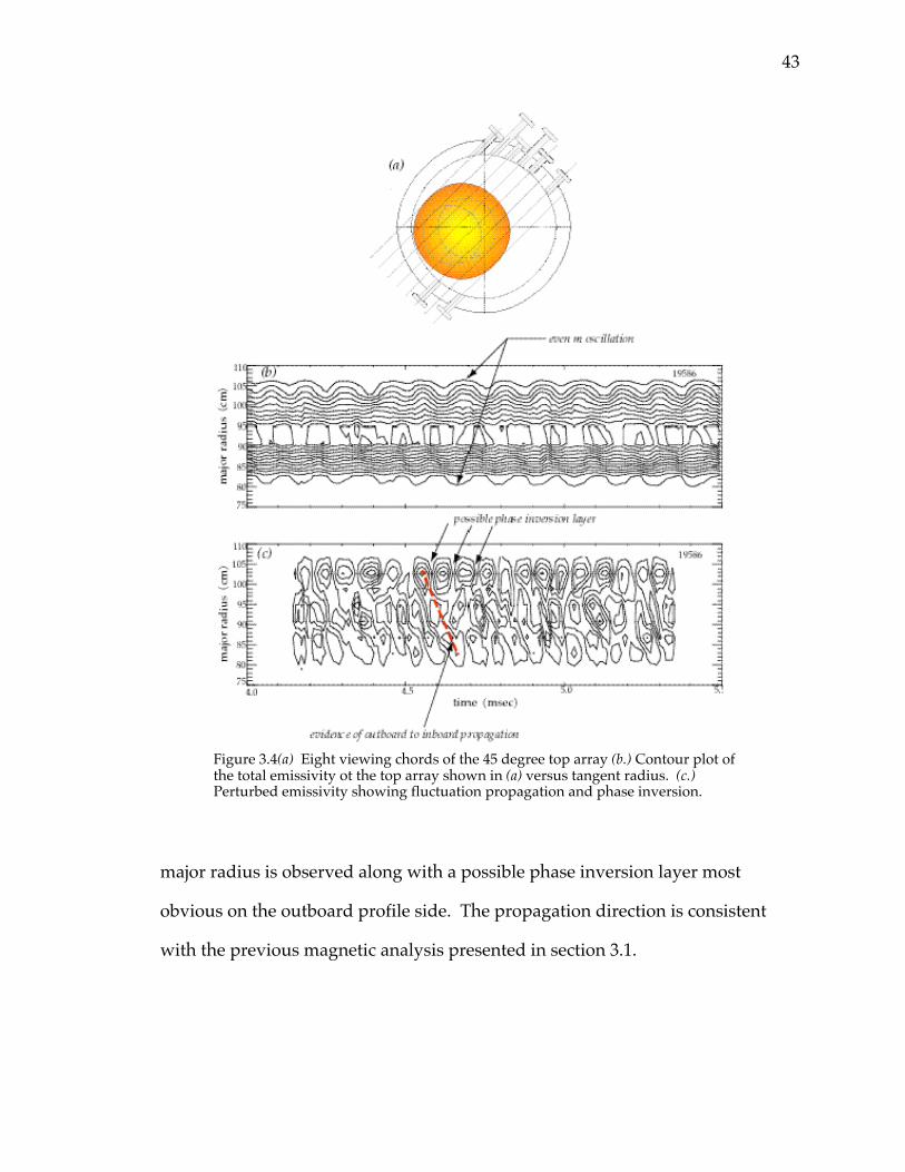
43
major radius is observed along with a possible phase inversion layer most
obvious on the outboard profile side. The propagation direction is consistent
with the previous magnetic analysis presented in section 3.1.
Figure 3.4(a) Eight viewing chords of the 45 degree top array (b.) Contour plot ofthe total emissivity ot the top array shown in (a) versus tangent radius. (c.)Perturbed emissivity showing fluctuation propagation and phase inversion.
44
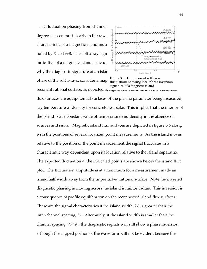
The fluctuation phasing from channel to channel has a local inversion of p
degrees is seen most clearly in the raw signals of figure 3.5. This is the telltale
characteristic of a magnetic island induced change of the emissivity profile as
noted by Xiao 1998. The soft x-ray signals show a local phase inversion
indicative of a magnetic island structure. To understand
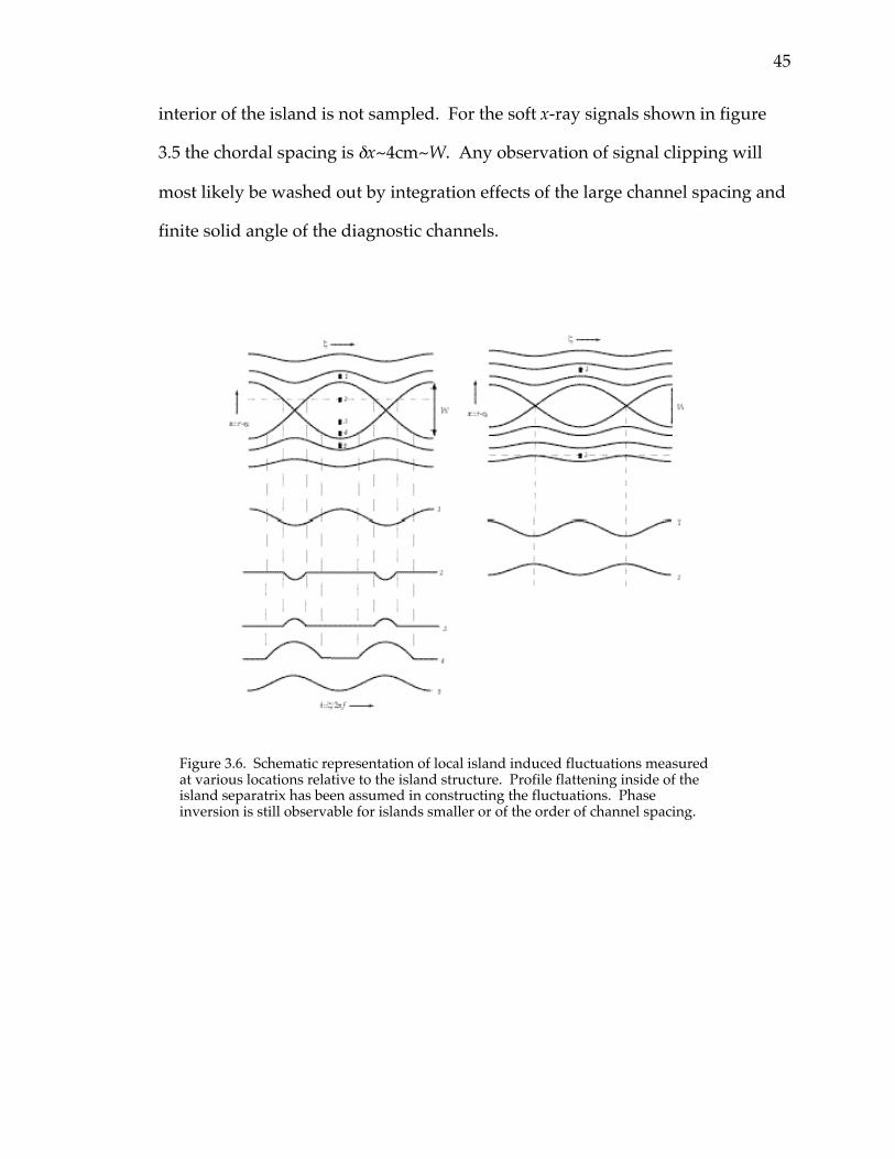
why the diagnostic signature of an island is a local inversion in the perturbation
phase of the soft x-rays, consider a map of the island flux surfaces near a
resonant rational surface, as depicted in figure 3.6. Assume that the perturbed
flux surfaces are equipotential surfaces of the plasma parameter being measured,
say temperature or density for concreteness sake. This implies that the interior of
the island is at a constant value of temperature and density in the absence of
sources and sinks. Magnetic island flux surfaces are depicted in figure 3.6 along
with the positions of several localized point measurements. As the island moves
relative to the position of the point measurement the signal fluctuates in a
characteristic way dependent upon its location relative to the island separatrix.
The expected fluctuation at the indicated points are shown below the island flux
plot. The fluctuation amplitude is at a maximum for a measurement made an
island half width away from the unperturbed rational surface. Note the inverted
diagnostic phasing in moving across the island in minor radius. This inversion is
a consequence of profile equilibration on the reconnected island flux surfaces.
These are the signal characteristics if the island width, W, is greater than the
inter-channel spacing, dx. Alternately, if the island width is smaller than the
channel spacing, W< dx, the diagnostic signals will still show a phase inversion
although the clipped portion of the waveform will not be evident because the
Figure 3.5. Unprocessed soft x-rayfluctuations showing local phase inversionsignature of a magnetic island
45
interior of the island is not sampled. For the soft x-ray signals shown in figure
3.5 the chordal spacing is dx~4cm~W. Any observation of signal clipping will
most likely be washed out by integration effects of the large channel spacing and
finite solid angle of the diagnostic channels.
Figure 3.6. Schematic representation of local island induced fluctuations measuredat various locations relative to the island structure. Profile flattening inside of theisland separatrix has been assumed in constructing the fluctuations. Phaseinversion is still observable for islands smaller or of the order of channel spacing.
49
3.3 Sawtooth oscillations and m/n=1/1 mode diagnosis
In this section an analysis method of core soft x-ray emissivity measurements is
developed that allows diagnosis of the m/n=1/1 instability in HBT-EP
sawtoothing discharges. This analysis allows study of m/n=1/1 mode behavior
during resonant magnetic perturbation experiments described in chapter five.
There m/n=1/1 mode frequency is used as an indicator of change in core plasma
rotation during external resonant magnetic perturbation experiments. This
analysis was developed to allow measurement estimates of the extent of core
viscous coupling to rotational change induced at the q=2 surface by the applied
magnetic perturbations. This attempt to quantify viscous diffusion into the core
was foiled due to the observed co-rotation of the m=1 and m=2 islands. Useful
information is still obtained, however, and the implications of induced core
rotation to the perturbed torque balance of chapter four will be discussed in
section 4.2.4.
In addition to core rotation the position of the q=1 surface inferred from the
m=1 emissivity perturbation analysis is also used to construct an average current
density and q(r) profile in conjunction with m=2 emissivity fluctuations observed
on the tomographic array and q* measurements in section 3.4. These average
profiles are then used to constrain the slope of the q(r) profile at the m/n=2/1
surface, dq dr( )q= 2 , in m=2 island width calculations in section 3.4.2.
50
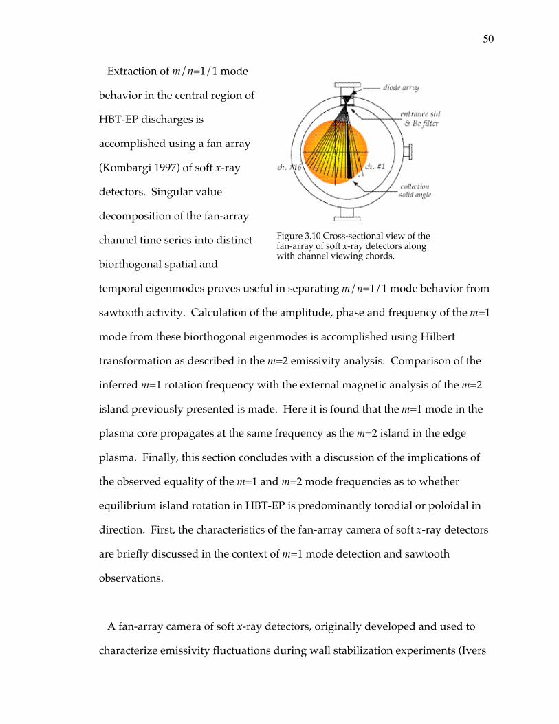
Extraction of m/n=1/1 mode
behavior in the central region of
HBT-EP discharges is
accomplished using a fan array
(Kombargi 1997) of soft x-ray
detectors. Singular value
decomposition of the fan-array
channel time series into distinct
biorthogonal spatial and
temporal eigenmodes proves useful in separating m/n=1/1 mode behavior from
sawtooth activity. Calculation of the amplitude, phase and frequency of the m=1
mode from these biorthogonal eigenmodes is accomplished using Hilbert
transformation as described in the m=2 emissivity analysis. Comparison of the
inferred m=1 rotation frequency with the external magnetic analysis of the m=2
island previously presented is made. Here it is found that the m=1 mode in the
plasma core propagates at the same frequency as the m=2 island in the edge
plasma. Finally, this section concludes with a discussion of the implications of
the observed equality of the m=1 and m=2 mode frequencies as to whether
equilibrium island rotation in HBT-EP is predominantly torodial or poloidal in
direction. First, the characteristics of the fan-array camera of soft x-ray detectors
are briefly discussed in the context of m=1 mode detection and sawtooth
observations.
A fan-array camera of soft x-ray detectors, originally developed and used to
characterize emissivity fluctuations during wall stabilization experiments (Ivers
Figure 3.10 Cross-sectional view of thefan-array of soft x-ray detectors alongwith channel viewing chords.
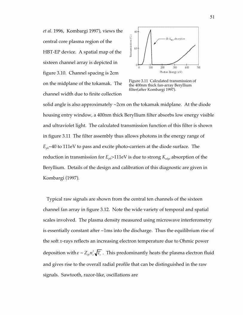
51
et al. 1996, Kombargi 1997), views the
central core plasma region of the
HBT-EP device. A spatial map of the
sixteen channel array is depicted in
figure 3.10. Channel spacing is 2cm
on the midplane of the tokamak. The
channel width due to finite collection
solid angle is also approximately ~2cm on the tokamak midplane. At the diode
housing entry window, a 400nm thick Beryllium filter absorbs low energy visible
and ultraviolet light. The calculated transmission function of this filter is shown
in figure 3.11 The filter assembly thus allows photons in the energy range of
Eph~40 to 111eV to pass and excite photo-carriers at the diode surface. The
reduction in transmission for Eph>111eV is due to strong Kedge absorption of the
Beryllium. Details of the design and calibration of this diagnostic are given in
Kombargi (1997).
Typical raw signals are shown from the central ten channels of the sixteen
channel fan array in figure 3.12. Note the wide variety of temporal and spatial
scales involved. The plasma density measured using microwave interferometry
is essentially constant after ~1ms into the discharge. Thus the equilibrium rise of
the soft x-rays reflects an increasing electron temperature due to Ohmic power
deposition withe ~ Zeff ne2 Te . This predominantly heats the plasma electron fluid
and gives rise to the overall radial profile that can be distinguished in the raw
signals. Sawtooth, razor-like, oscillations are
Figure 3.11 Calculated transmission ofthe 400nm thick fan-array Berylliumfilter(after Kombargi 1997).
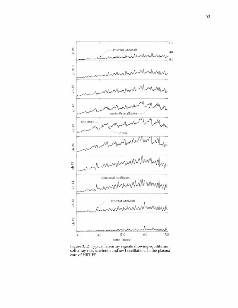
52
Figure 3.12 Typical fan-array signals showing equilibriumsoft x-ray rise, sawtooth and m=1 oscillations in the plasmacore of HBT-EP.
53
prevalent on the central channels and become smaller and inverted at larger
values of minor radius. The sawtooth rise is approximately linear and abruptly
crashes on a time scale roughly ~10 times shorter than the rising portion of the
sawtooth. Still other channels have more sinusoidal-like oscillations present at
intermediate positions between the rising sawteeth in the core region and small
inverted sawteeth on the peripheral channels.
Sawtooth relaxation oscillations, sometimes termed internal disruptions, were
first observed on the ST tokamak at Princeton (von Goeler et al 1974) and have
been an active area of fusion plasma physics research over the ensuing years.
Our purpose here is not to study sawtooth physics, but to use known properties
of sawtooth phenomenology in order to interpret HBT-EP sawtooth activity. In
particular, the position of the q=1 surface and the frequency of the resonant
m/n=1/1 mode will be used in the following study of m/n=2/1 magnetic island
frequency locking behavior under the action of externally applied resonant
magnetic perturbations. A brief survey of sawtooth physics is given next to
motivate the association of a q=1 mode rational surface and its associated
m/n=1/1 instability with observed HBT-EP sawtooth behavior.
3.3.1 Sawtooth phenomenology and HBT-EP sawteeth
The relaxation oscillations, or sawteeth, that ride atop the equilibrium
emissivity depicted in figure 3.12 are driven by a combination of thermal and
magnetohydrodynamic instability. The rising portion of the sawtooth oscillation
is the result of Ohmic heating deposition in the core plasma. The Ohmic heat
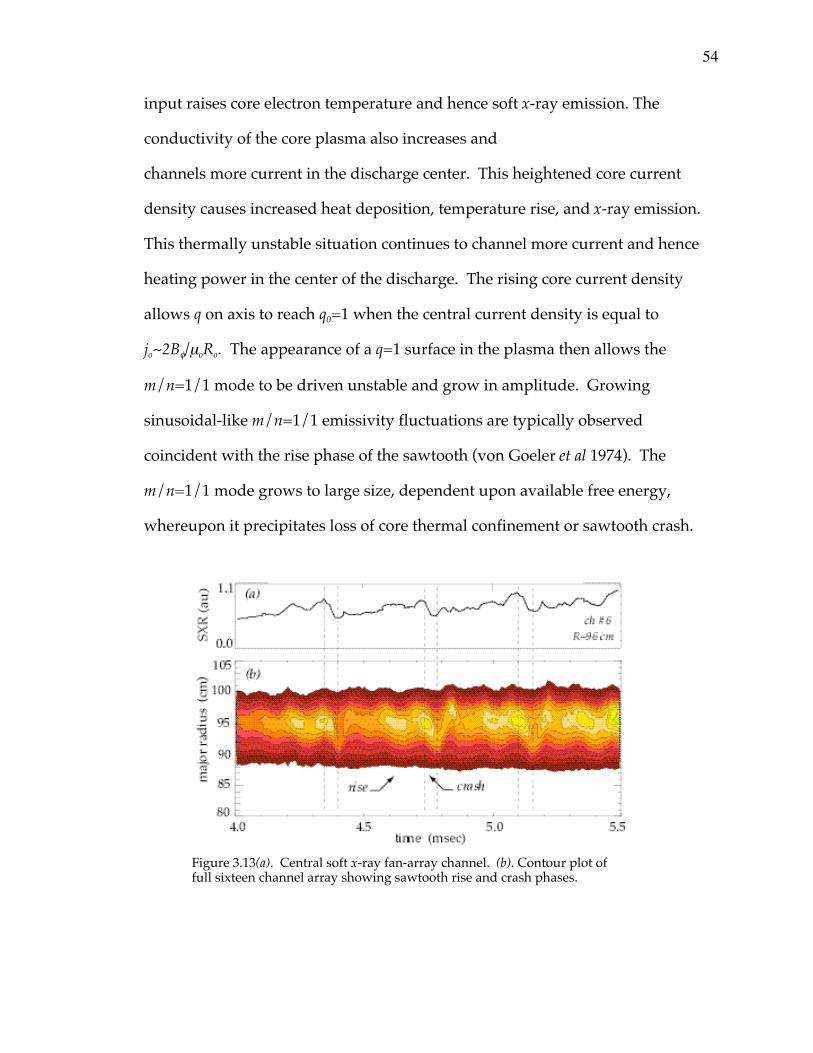
54
input raises core electron temperature and hence soft x-ray emission. The
conductivity of the core plasma also increases and
channels more current in the discharge center. This heightened core current
density causes increased heat deposition, temperature rise, and x-ray emission.
This thermally unstable situation continues to channel more current and hence
heating power in the center of the discharge. The rising core current density
allows q on axis to reach q0=1 when the central current density is equal to
jo~2Bf/moRo. The appearance of a q=1 surface in the plasma then allows the
m/n=1/1 mode to be driven unstable and grow in amplitude. Growing
sinusoidal-like m/n=1/1 emissivity fluctuations are typically observed
coincident with the rise phase of the sawtooth (von Goeler et al 1974). The
m/n=1/1 mode grows to large size, dependent upon available free energy,
whereupon it precipitates loss of core thermal confinement or sawtooth crash.
Figure 3.13(a). Central soft x-ray fan-array channel. (b). Contour plot offull sixteen channel array showing sawtooth rise and crash phases.
55
The exact nature of the crash phase is unknown and varies depending upon
numerous factors, in particular collisionality (Wesson 1991).
An early theoretical sawtooth model, due to Kadomtsev, based on an m=1
island growing nonlinearly until it envelopes the entire core region (Kadomtsev
1975) has numerical (Sykes and Wesson 1976) and experimental (Jahns et al 1978,
Goetz et al 1990) evidence supporting a complete reconnection model of the
sawtooth oscillation. However, doubt was cast on this simple senario in other
experimental studies (Dubois et al 1980, Snipes and Gentle 1986) where observed
m=1 oscillations continue throughout the entire sawtooth cycle. Theoretical
models have been developed to explain observed core temperature collapse in
the absence of Kadomstsev-style core envelopment and complete reconnection of
the m/n=1/1 island. These models invoke other physical mechanisms during
the nonlinear development of the m/n=1/1 mode to bring about loss of
confinement and hence sawtooth crash, including enhanced turbulence (Dubois
et al 1983), magnetic stochasticity (Lichtenberg 1984) and recently ballooning
effects (Nishimura et al 1998) among others.
For the present study, we wish to skirt difficulties in current understanding of
tokamak sawteeth, and use the well-known fact that they are associated with a
m/n=1/1 mode resonant at the q=1 surface in the plasma core. This information
allows the position of the q=1 surface and the amplitude, phase, and frequency of
the m=1 mode to be interpreted from the fan array signals. Next we discuss the
extraction of the q=1 position and m/n=1/1 mode information from typical fan-
56
array data. This is accomplished using singular value decomposition and Hilbert
transformation of the fan-array channel time series
3.3.2 Singular value decomposition and m/n=1/1mode diagnosis
Consider a function of both space and time such as the poloidal field at the
edge of the plasma Bq(q,t) or the soft x-ray emissivity as a function of channel
number and time e(l,t). Singular value decomposition is a familiar form of
matrix reduction from linear algebra, and has well known applications in solving
for pseudo-inverse matrices in systems of linear equations. Rather than using the
decomposition to project onto a specified solution space, we investigate the
individual eigenmodes of the decomposition and interpret them physically. This
approach to using the singular eigenmodes has its origins in nonlinear dynamics
(Aubry et al 1991) where it has been used to study wave propagation in
hydrodynamic systems (Aubry et al 1994) and chaotic bifurcation events (Lima
1992). In a plasma context, it is particularly well suited for distinguishing
coherent structures and phenomena from background turbulence and random
noise. It has been profitably used in x-ray and magnetic measurements of MHD
mode structure (Nardone 1992, Kim et al 1999), sawtooth behavior (Dudok de
Wit 1995), and perturbative transport studies (Dudok de Wit et al 1998) in a
fusion plasma physics context.
57
The singular value or biorthogonal decomposition of such a spatio-temporal
signal set consists of a representation that attempts to split the time and space
dependent information of a bivariate function into an expansion of the form,
f x ,t( ) = Akfk x( )y k t( )k
 . (3.12)
The spatial basis functions jk sometimes referred to as topos (Aubry et al 1991),
and temporal basis yk functions or chronos are so constructed that they are
orthonormal to the other members of their respective eigen-set as follows:
f i x( )fk x( )dxÚ = d ik , (3.13)
y i t( )Ú y k t( )dt = dik . (3.14)
Here dik is the Kronecker delta and the integrations in 3.13 and 3.14 are over the
relevant spatial and temporal domains of the time series involved. The Ak
coefficients in the expansion of equation 3.12 measure the contribution of each (jk
,yk) to the total signal and can also be interpreted as eigenvalues of an associated
eigenvalue problem (Noble and Gentle 1978). The biorthogonal components of
equations 3.12 to 3.14 are determined from the soft x-ray measurements using
singular value decomposition. Take a matrix of observational channels,
y xk , ti( ) = Y( )ik , with y(xk,ti) the sampled version of some scalar field, in this case
the measured soft x-ray flux. The spatial and temporal eigenmodes are
constructed using singular value decomposition, Y = VAU * . The vectors
V = y1,y 2 ,K ,y M[ ] and U = j1 ,j2 ,K,jM[ ] contain the spatial and temporal
eigenmodes of equation 3.12, and the diagonal matrix A contains the expansion
coefficients or singular values.
58
A difficulty in employing an expansion of the type of equation 3.12 is in
interpreting the resulting series. Since the basis functions are constructed from
the data itself a simple interpretation is often lacking. In the special case of
sinusoidal oscillation the decomposition is equivalent to Fourier analysis (Dudok
de Wit et al 1994). This implies that sinusoidally varying structures will appear
in distinct eigenmodes with an invariant spatial structure mode and a temporal
eigenmode that reflects frequency and amplitude change of the structure in
question. For the soft x-ray signals discussed here, since the phenomena under
study are in some sense well known, interpretation is relatively straightforward.
For use here in analyzing the fan-array multi-channel data set the biorthogonal
decomposition is useful for two distinct reasons. In fan array observations of
core sawtooth and m/n=1/1 mode activity the raw soft x-ray signals have
essentially four characteristic time scales associated
with macroscopic, coherent plasma behavior. The background equilibrium
emission value typically changes over a few milliseconds time scale due to global
profile evolution. The sawtooth oscillation has two characteristic time scales
associated with it. The sawtooth rise time is approximately ~300 to 400msec
depending upon discharge conditions, while the crash time is of order ~50msec.
The m/n=1/1 mode rotation period sets an intermediate scale between the
sawtooth rise and fall times. Typically, two to three oscillation cycles or periods
of the m/n=1/1 mode per sawtooth period are observed. Here the sawtooth
period is defined as the sum of the rise and crash time scales, tST~400 to 500msec .
Thus, the m/n=1/1 mode period is approximately ~100 to 200msec. It is thus
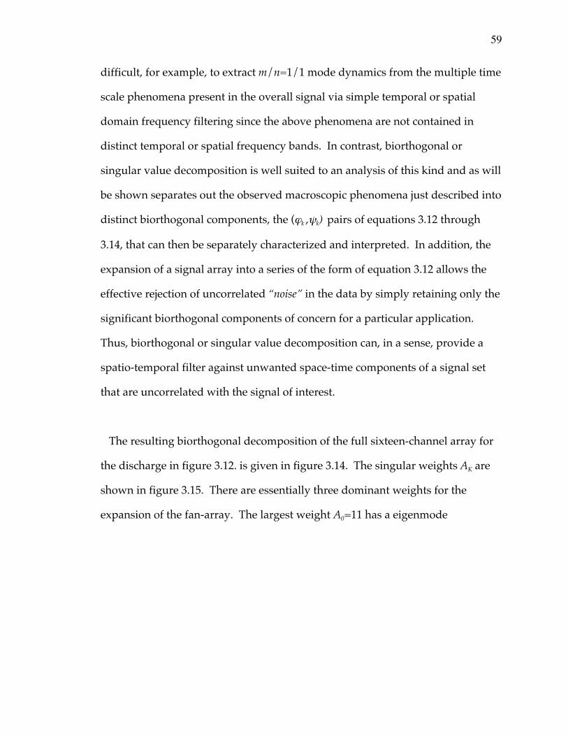
59
difficult, for example, to extract m/n=1/1 mode dynamics from the multiple time
scale phenomena present in the overall signal via simple temporal or spatial
domain frequency filtering since the above phenomena are not contained in
distinct temporal or spatial frequency bands. In contrast, biorthogonal or
singular value decomposition is well suited to an analysis of this kind and as will
be shown separates out the observed macroscopic phenomena just described into
distinct biorthogonal components, the (jk ,yk) pairs of equations 3.12 through
3.14, that can then be separately characterized and interpreted. In addition, the
expansion of a signal array into a series of the form of equation 3.12 allows the
effective rejection of uncorrelated “noise” in the data by simply retaining only the
significant biorthogonal components of concern for a particular application.
Thus, biorthogonal or singular value decomposition can, in a sense, provide a
spatio-temporal filter against unwanted space-time components of a signal set
that are uncorrelated with the signal of interest.
The resulting biorthogonal decomposition of the full sixteen-channel array for
the discharge in figure 3.12. is given in figure 3.14. The singular weights AK are
shown in figure 3.15. There are essentially three dominant weights for the
expansion of the fan-array. The largest weight A0=11 has a eigenmode
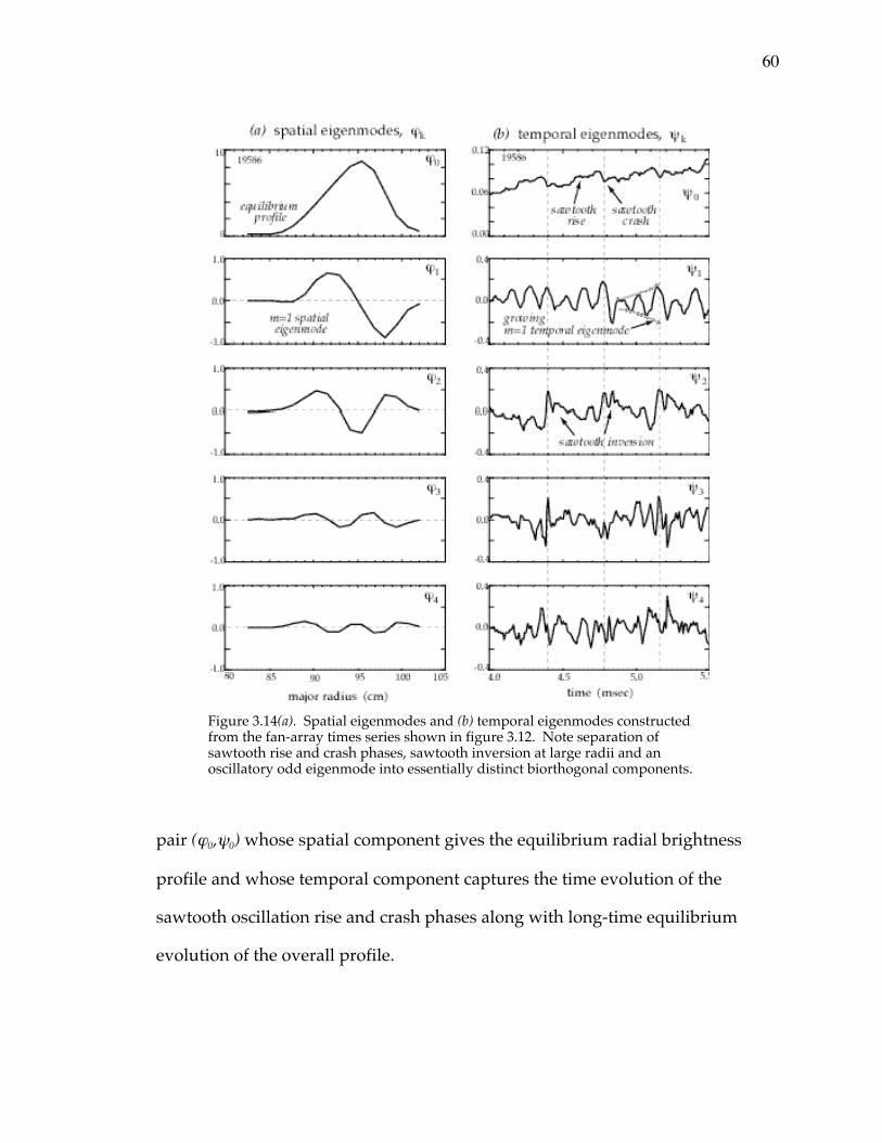
60
pair (j0,y0) whose spatial component gives the equilibrium radial brightness
profile and whose temporal component captures the time evolution of the
sawtooth oscillation rise and crash phases along with long-time equilibrium
evolution of the overall profile.
Figure 3.14(a). Spatial eigenmodes and (b) temporal eigenmodes constructedfrom the fan-array times series shown in figure 3.12. Note separation ofsawtooth rise and crash phases, sawtooth inversion at large radii and anoscillatory odd eigenmode into essentially distinct biorthogonal components.
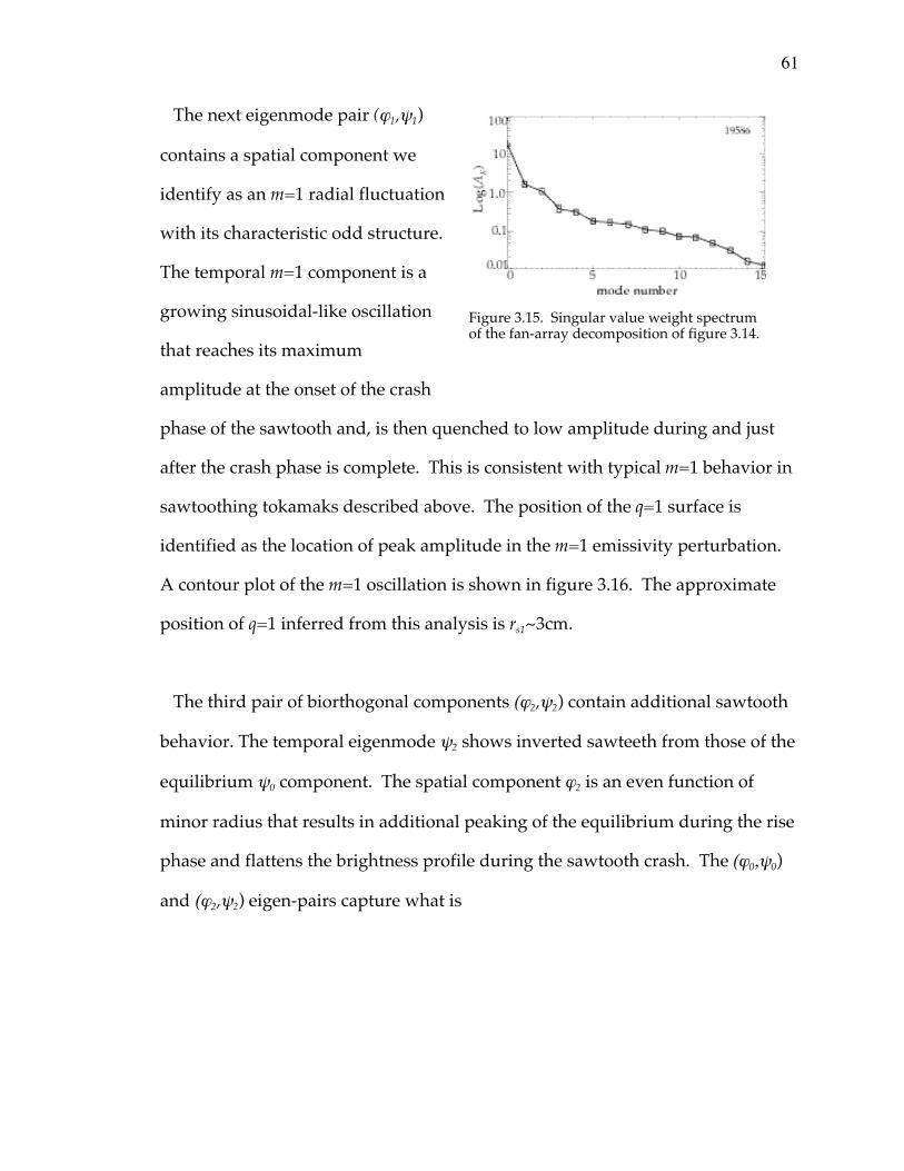
61
The next eigenmode pair (j1,y1)
contains a spatial component we
identify as an m=1 radial fluctuation
with its characteristic odd structure.
The temporal m=1 component is a
growing sinusoidal-like oscillation
that reaches its maximum
amplitude at the onset of the crash
phase of the sawtooth and, is then quenched to low amplitude during and just
after the crash phase is complete. This is consistent with typical m=1 behavior in
sawtoothing tokamaks described above. The position of the q=1 surface is
identified as the location of peak amplitude in the m=1 emissivity perturbation.
A contour plot of the m=1 oscillation is shown in figure 3.16. The approximate
position of q=1 inferred from this analysis is rs1~3cm.
The third pair of biorthogonal components (j2,y2) contain additional sawtooth
behavior. The temporal eigenmode y2 shows inverted sawteeth from those of the
equilibrium y0 component. The spatial component j2 is an even function of
minor radius that results in additional peaking of the equilibrium during the rise
phase and flattens the brightness profile during the sawtooth crash. The (j0,y0)
and (j2,y2) eigen-pairs capture what is
Figure 3.15. Singular value weight spectrumof the fan-array decomposition of figure 3.14.
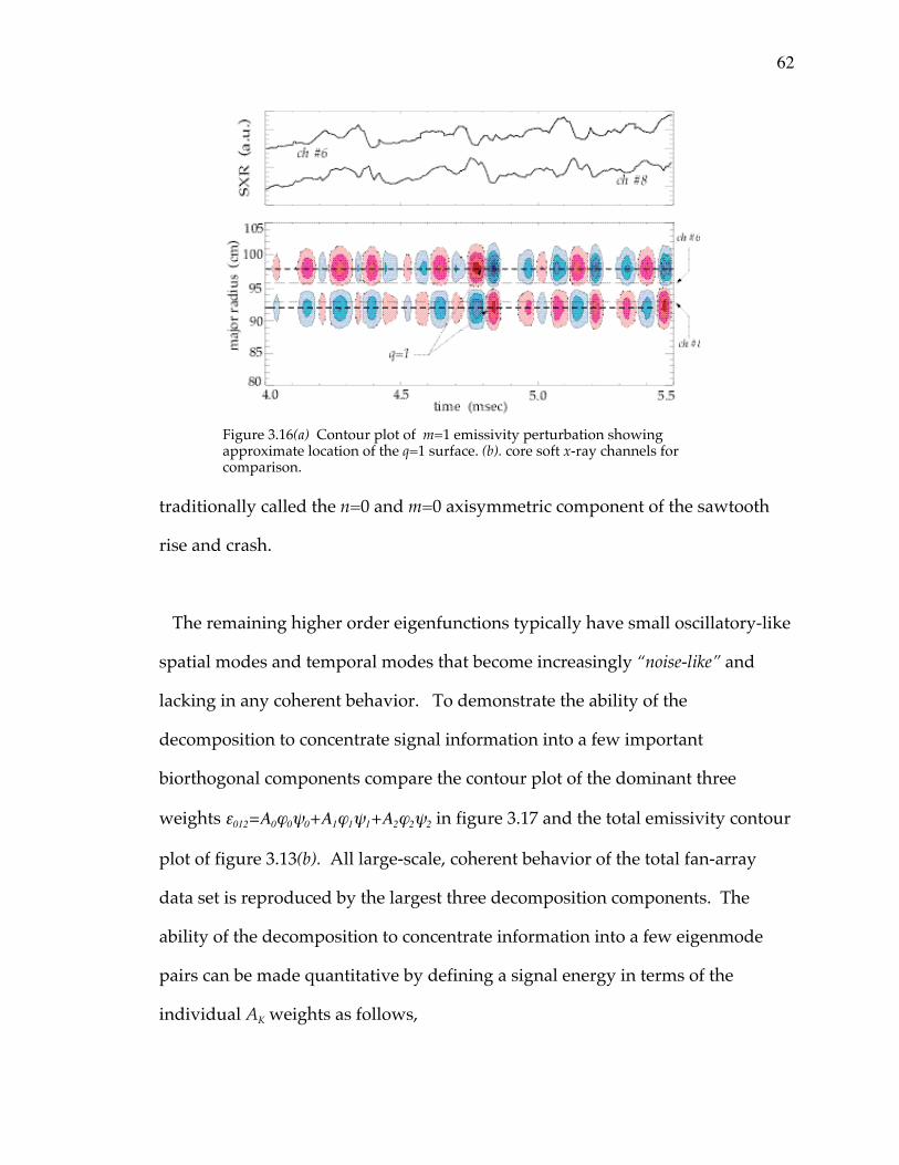
62
traditionally called the n=0 and m=0 axisymmetric component of the sawtooth
rise and crash.
The remaining higher order eigenfunctions typically have small oscillatory-like
spatial modes and temporal modes that become increasingly “noise-like” and
lacking in any coherent behavior. To demonstrate the ability of the
decomposition to concentrate signal information into a few important
biorthogonal components compare the contour plot of the dominant three
weights e012=A0j0y0+A1j1y1+A2j2y2 in figure 3.17 and the total emissivity contour
plot of figure 3.13(b). All large-scale, coherent behavior of the total fan-array
data set is reproduced by the largest three decomposition components. The
ability of the decomposition to concentrate information into a few eigenmode
pairs can be made quantitative by defining a signal energy in terms of the
individual AK weights as follows,
Figure 3.16(a) Contour plot of m=1 emissivity perturbation showingapproximate location of the q=1 surface. (b). core soft x-ray channels forcomparison.
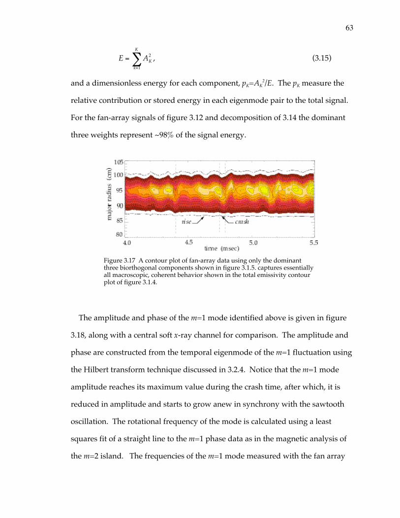
63
E = AK2
k=1
K
 , (3.15)
and a dimensionless energy for each component, pK=AK2/E. The pK measure the
relative contribution or stored energy in each eigenmode pair to the total signal.
For the fan-array signals of figure 3.12 and decomposition of 3.14 the dominant
three weights represent ~98% of the signal energy.
The amplitude and phase of the m=1 mode identified above is given in figure
3.18, along with a central soft x-ray channel for comparison. The amplitude and
phase are constructed from the temporal eigenmode of the m=1 fluctuation using
the Hilbert transform technique discussed in 3.2.4. Notice that the m=1 mode
amplitude reaches its maximum value during the crash time, after which, it is
reduced in amplitude and starts to grow anew in synchrony with the sawtooth
oscillation. The rotational frequency of the mode is calculated using a least
squares fit of a straight line to the m=1 phase data as in the magnetic analysis of
the m=2 island. The frequencies of the m=1 mode measured with the fan array
Figure 3.17 A contour plot of fan-array data using only the dominantthree biorthogonal components shown in figure 3.1.5. captures essentiallyall macroscopic, coherent behavior shown in the total emissivity contourplot of figure 3.1.4.
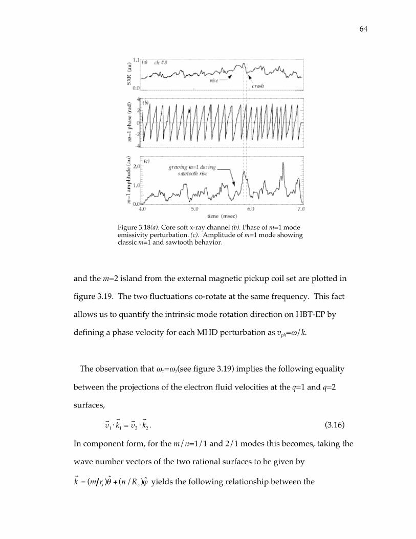
64
and the m=2 island from the external magnetic pickup coil set are plotted in
figure 3.19. The two fluctuations co-rotate at the same frequency. This fact
allows us to quantify the intrinsic mode rotation direction on HBT-EP by
defining a phase velocity for each MHD perturbation as vph=w/k.
The observation that w1=w2(see figure 3.19) implies the following equality
between the projections of the electron fluid velocities at the q=1 and q=2
surfaces,
rv1 ⋅
rk1 =
rv2 ⋅
rk2 . (3.16)
In component form, for the m/n=1/1 and 2/1 modes this becomes, taking the
wave number vectors of the two rational surfaces to be given by
rk = (m rs )q + (n/Ro )j yields the following relationship between the
Figure 3.18(a). Core soft x-ray channel (b). Phase of m=1 modeemissivity perturbation. (c). Amplitude of m=1 mode showingclassic m=1 and sawtooth behavior.
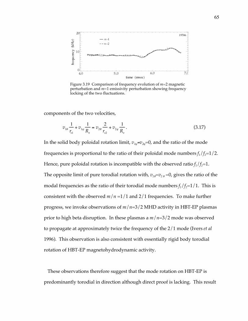
65
components of the two velocities,
v1q1rs1
+ v1j
1Ro
= v2q
2rs2
+ v2j
1Ro
. (3.17)
In the solid body poloidal rotation limit, v1j=v2j=0, and the ratio of the mode
frequencies is proportional to the ratio of their poloidal mode numbers f1/f2=1/2.
Hence, pure poloidal rotation is incompatible with the observed ratio f1/f2=1.
The opposite limit of pure torodial rotation with, v1q=v2 q =0, gives the ratio of the
modal frequencies as the ratio of their torodial mode numbers f1/f2=1/1. This is
consistent with the observed m/n =1/1 and 2/1 frequencies. To make further
progress, we invoke observations of m/n=3/2 MHD activity in HBT-EP plasmas
prior to high beta disruption. In these plasmas a m/n=3/2 mode was observed
to propagate at approximately twice the frequency of the 2/1 mode (Ivers et al
1996). This observation is also consistent with essentially rigid body torodial
rotation of HBT-EP magnetohydrodynamic activity.
These observations therefore suggest that the mode rotation on HBT-EP is
predominantly torodial in direction although direct proof is lacking. This result
Figure 3.19 Comparison of frequency evolution of m=2 magneticperturbation and m=1 emissivity perturbation showing frequencylocking of the two fluctuations.

66
will be quantified further in chapter four, where an analysis of the perturbed
torque balance near the m/n=2/1 surface is presented and the limiting cases of
only poloidal or torodial motion are considered again in the context of mode
locking to applied resonant magnetic perturbations.
75
4.0 Resonant magnetic perturbation experiments
Resonant magnetic perturbations are used to study and control island rotation
dynamics in this chapter. A simple compact saddle coil system is demonstrated
to have significant impact on inducing magnetic island frequency and amplitude
change. Details of the island control system developed on HBT-EP are described
first in section 4.1, before magnetic island frequency and amplitude effects are
presented in section 4.2 and 4.3.
Basic frequency locking characteristics of HBT-EP magnetic islands are
described using the diagnostic analysis tools developed in chapter three in
section 4.2. A model of the perturbed electromagnetic, viscous, and inertial
torque balance near a large amplitude magnetic island is developed following
traditional mode-locking theory and compared with experimental order of
magnitude estimates of the various torque contributions. Implications of the
experimental torque balance in relation to poloidal and toroidal equilibrium
island rotation and possible poloidal flow damping mechanisms is discussed
next. The experimental torque required to lock an island is shown to be
consistent with toroidally driven magnetic island motion by the rotating control
fields. This implies the effect of substantial poloidal flow damping of any
possible poloidally driven motion by the magnetic perturbation. The observed
locking torque magnitude and the effects of flow damping are also important for
the evolution of magnetic island size due to the effective renormalization of ion
inertia in a poloidally flow damped system (Smolyakov et al 1995). The
observation of core induced motion as indicated by the m/n=1/1 emissivity
76
fluctuation analysis during the rotation control experiments of the 2/1 island are
presented next and the implications for driving sheared rotation employing two
distinct rational surfaces in the plasma is discussed in section 4.2.1.
Observed island amplitude dynamics are discussed next. Using frequency
modulated perturbations to drive island rotational change, the amplitude of
these islands is observed to be affected by this magnetic stirring. Study of an
ensemble of similarly prepared plasmas indicates a correlation between magnetic
island frequency modulation and the growth and damping of magnetic island
size. More specifically, accelerated magnetic islands are observed to grow in
amplitude and those that are decelerated are damped in size. Simple estimates
of the possible effect of inertia as agent of the observed island suppression are
presented. The observed asymmetric response is then shown to be consistent
with a destabilizing inertial term in Rutherford’s island width evolution equation
(Waelbroeck and Fitzpatrick 1997). Finally, this chapter concludes with the
demonstration of disruption mitigation using this simple asynchronous saddle
coil control technique.

77
4.1 HBT-EP magnetic island control system
Active control of magnetic islands on the HBT-EP tokamak is accomplished
with a saddle coil system
consisting of four coils
connected to approximate a
quadrature m/n=2/1
dominant magnetic field
structure. The coils are
wound out of nine turns of #1
copper cable and are situated
on the quartz insulating
breaks (see figure 4.0)
between vacuum chamber
sections. Each coil spans a toroidal angle of ~6o separately. In the quadrature
configuration used to generate a rotating magnetic field the toroidal coverage per
phase is ~3.5o. Placement of the coils on the quartz insulating segments of the
vacuum chamber allows high frequency fSC~20kHz perturbation fields to easily
couple to the plasma magnetic island by injecting the perturbing field through
the Aluminum passive stabilizing wall gaps shown in figure 4.1. This introduces
minimal attenuation and phase shift to the applied control field. The saddle coil
current feed and return are in a twisted pair configuration and are run to the
center cylinder enclosing the Ohmic transformer. Each coil pair can be easily
disconnected and the configuration changed to a single-phase coil set with
appropriate poloidal reorientation of the toroidal current elements. The saddle
Figure 4.0 Top view of the HBT-EP tokamak showingthe toroidal location of the m/n=2/1 saddle coil set.Quartz sections are denoted by yellow.
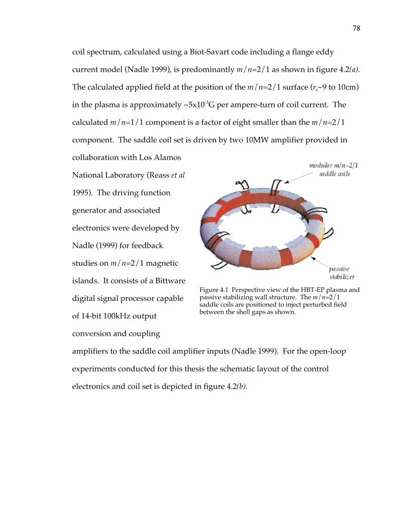
78
coil spectrum, calculated using a Biot-Savart code including a flange eddy
current model (Nadle 1999), is predominantly m/n=2/1 as shown in figure 4.2(a).
The calculated applied field at the position of the m/n=2/1 surface (rs~9 to 10cm)
in the plasma is approximately ~5x10⁻³G per ampere-turn of coil current. The
calculated m/n=1/1 component is a factor of eight smaller than the m/n=2/1
component. The saddle coil set is driven by two 10MW amplifier provided in
collaboration with Los Alamos
National Laboratory (Reass et al
1995). The driving function
generator and associated
electronics were developed by
Nadle (1999) for feedback
studies on m/n=2/1 magnetic
islands. It consists of a Bittware
digital signal processor capable
of 14-bit 100kHz output
conversion and coupling
amplifiers to the saddle coil amplifier inputs (Nadle 1999). For the open-loop
experiments conducted for this thesis the schematic layout of the control
electronics and coil set is depicted in figure 4.2(b).
Figure 4.1 Perspective view of the HBT-EP plasma andpassive stabilizing wall structure. The m/n=2/1saddle coils are positioned to inject perturbed fieldbetween the shell gaps as shown.
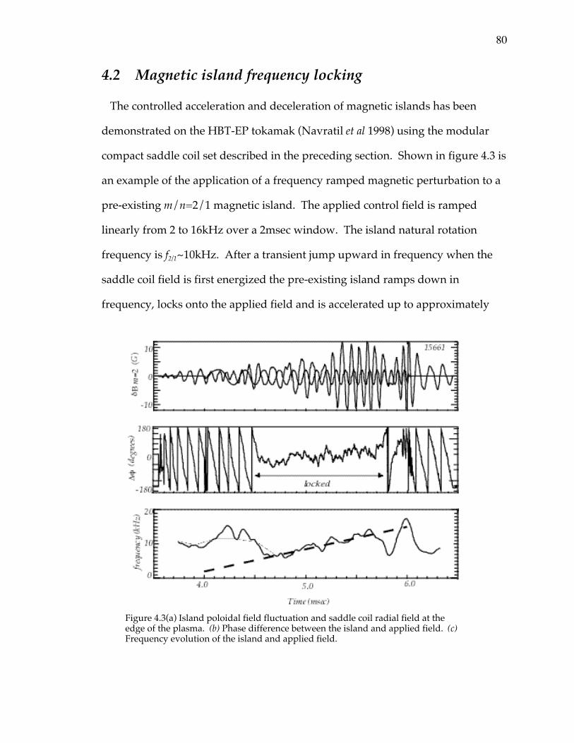
80
4.2 Magnetic island frequency locking
The controlled acceleration and deceleration of magnetic islands has been
demonstrated on the HBT-EP tokamak (Navratil et al 1998) using the modular
compact saddle coil set described in the preceding section. Shown in figure 4.3 is
an example of the application of a frequency ramped magnetic perturbation to a
pre-existing m/n=2/1 magnetic island. The applied control field is ramped
linearly from 2 to 16kHz over a 2msec window. The island natural rotation
frequency is f2/1~10kHz. After a transient jump upward in frequency when the
saddle coil field is first energized the pre-existing island ramps down in
frequency, locks onto the applied field and is accelerated up to approximately
Figure 4.3(a) Island poloidal field fluctuation and saddle coil radial field at theedge of the plasma. (b) Phase difference between the island and applied field. (c)Frequency evolution of the island and applied field.
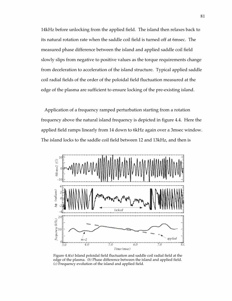
81
14kHz before unlocking from the applied field. The island then relaxes back to
its natural rotation rate when the saddle coil field is turned off at 6msec. The
measured phase difference between the island and applied saddle coil field
slowly slips from negative to positive values as the torque requirements change
from deceleration to acceleration of the island structure. Typical applied saddle
coil radial fields of the order of the poloidal field fluctuation measured at the
edge of the plasma are sufficient to ensure locking of the pre-existing island.
Application of a frequency ramped perturbation starting from a rotation
frequency above the natural island frequency is depicted in figure 4.4. Here the
applied field ramps linearly from 14 down to 6kHz again over a 3msec window.
The island locks to the saddle coil field between 12 and 13kHz, and then is
Figure 4.4(a) Island poloidal field fluctuation and saddle coil radial field at theedge of the plasma. (b) Phase difference between the island and applied field.(c) Frequency evolution of the island and applied field.

82
dragged down in frequency by the control field. Island rotation is slowed down
to approximately 7kHz before unlocking, ramping up slightly, and then
returning to its natural rate of f2/1~10kHz. Note that the relative phase in this
case slowly slips from positive to negative values as the torque requirements
change from acceleration to deceleration of the island. This can be contrasted
with the “ramp-up” applied control field in figure 4.3 which has the opposite
phase difference evolution. Induced ion flow during these magnetic stirring
experiments has been confirmed with several km per second change in ion fluid
toroidal rotation (Navratil et al 1998, Talyor 2000).
These HBT-EP experiments on rotation control of an island embedded in
plasma form the basis for future work directed at generating sheared flows using
two distinct rational surfaces to apply electromagnetic torque and hence drive
differential rotation (Jensen et al 1994). They have demonstrated a simple
compact coil technique compatible with passive stabilization requirements
necessary for future high beta advanced tokamak operation scenarios while
offering a relatively “low-tech” approach to inducing or controlling plasma flow.
To further understand the magnetic island-saddle coil interaction the perturbed
torque balance near an HBT-EP magnetic island is estimated next.
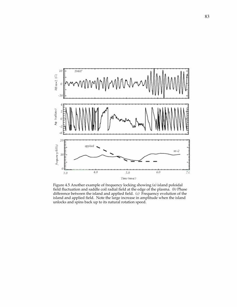
83
Figure 4.5 Another example of frequency locking showing (a) island poloidalfield fluctuation and saddle coil radial field at the edge of the plasma. (b) Phasedifference between the island and applied field. (c) Frequency evolution of theisland and applied field. Note the large increase in amplitude when the islandunlocks and spins back up to its natural rotation speed.

84
84
4.2.1 Torque balance near a magnetic island
In this section we estimate the perturbed torque balance near an HBT-EP
magnetic island. The standard mode locking island theory developed over
the past several years (Fitzpartick and Hender 1992, Jensen et al 1993,
Fitzpatrick 1994, Boozer 1996, Hegna et al 1998) is employed to understand
the magnetic island-saddle coil interaction. The perturbed torque balance is
separated into poloidal and toroidal directed torque components for
convenience. A simple model for poloidal flow damping due to magnetic
pumping of the ion fluid is developed in section 4.2.3. Finally, the effect of
core induced rotation during these magnetic stirring experiments as
measured by the emissivity analysis of section 3.3 is discussed in the context
of this torque balance analysis. Implications for driving sheared flow in HBT-
EP plasmas using different helicities of applied magnetic perturbations is also
reviewed given the co-rotation of the m/n=1/1 island with the 2/1 island.
Next, the traditional perturbed island torque balance is described and
experimental order of magnitude estimates of the various torque terms are
calculated.
4.2.1.1 Saddle coil electromagnetic torque
The electromagnetic torque acting upon the island region is given simply by
integrating the perturbed Lorentz force density over the volume of the island
(Fitzpatrick 1994, Hegna et al 1998). Thus we have,
GEMz = Rz ⋅rj ¥
rb d 3x
WÚ (4.1)
85
GEMq = rq ⋅rj ¥
rb d3x
WÚ (4.2)
with the applied resonant magnetic perturbation rb crossed into the perturbed
island current density rj at the rational surface. In the outer region, away
from the singular layer centered at the rational surface, ideal MHD is valid
and no net electromagnetic torque acts due to the applied perturbation. The
plasma away from the resonance therefore simply displaces in response to the
applied field. The electromagnetic torque acts only in the inner region. The
perturbed current is approximately given by j @ ¢D d(r - rs )Y . The torodial
electromagnetic torque acting at the rational surface is therefore given by,
GEMz = drrs -W /2
rs +W /2
Ú rR dq0
2p
Ú Rz ⋅rj ¥
rb df
0
2p
Ú (4.3)
which can be expressed in terms of the magnetic potential and delta prime as
(Fitzpatrick 1994, Hegna et al 1998),
GEMz = 8p 2Rn Im rs ¢D y s
2( ) . (4.4)
The imaginary part of equation 4.4 leads to a torque that modulates as
GEM~sin(Df), with Df=fW-fSC the phase difference between the island and
applied perturbation. The torodial and poloidal electromagnetic torques are
related by,
GEMq = -mn
GEMz . (4.5)
Thus, for a tokamak resonance the electromagnetic torque is slightly more
poloidal than toroidal since m≥n, whereas for example, in a reversed field
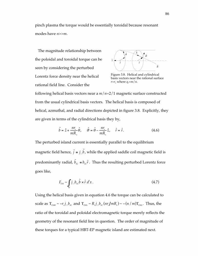
86
pinch plasma the torque would be essentially toroidal because resonant
modes have n>>m.
The magnitude relationship between
the poloidal and toroidal torque can be
seen by considering the perturbed
Lorentz force density near the helical
rational field line. Consider the
following helical basis vectors near a m/n=2/1 magnetic surface constructed
from the usual cylindrical basis vectors. The helical basis is composed of
helical, azmuthal, and radial directions depicted in figure 3.8. Explicitly, they
are given in terms of the cylindrical basis they by,
b = z +nrs
mRo
q , J = q -nrs
mRo
z, r = r. (4.6)
The perturbed island current is essentially parallel to the equilibrium
magnetic field hence, rj @ j//b , while the applied saddle coil magnetic field is
predominantly radial, rbSC @ bSCr . Thus the resulting perturbed Lorentz force
goes like,
FEM ~ j//bSCb ¥ r d3WÚ x . (4.7)
Using the helical basis given in equation 4.6 the torque can be calculated to
scale as TEMq ~ -rs j//bSC and TEMz ~ Ro j//bSC (nrs mRo ) ~ - (n/m)TEMz . Thus, the
ratio of the toroidal and poloidal electromagnetic torque merely reflects the
geometry of the resonant field line in question. The order of magnitude of
these torques for a typical HBT-EP magnetic island are estimated next.
zr
qJ
r
h
rB
Figure 3.8. Helical and cylindricalbasis vectors near the rational surfacer=rs where qs=m/n.
87
The poloidal field fluctuation mapped backed to the approximate location
of the m/n=2/1 magnetic island is of order 10 to 20G for an island width of a
few centimeters as described in section 3.4.2. Therefore, the perturbed island
current density is approximately j//(rs ) ~ bq (rs )/ moW ~ 4A/cm2 . The radial
saddle coil magnetic field at the plasma surface to ensure locking is typically
of order the poloidal field fluctuation at the edge of the plasma. Mapping this
field strength to the approximate position of the magnetic gives bSC(rs)~2G.
The perturbed Lorentz force density FEM is of order FEM~j//bSC~20mN/cm3 and
the resultant torque has a magnitude of approximately TEM~rsFEMVW~70x10-3
Nm, with rs the radius of the rational surface and VW the effective annular
volume of the magnetic island. Next, the balancing viscous restoring torque
and the inertial torque due to island acceleration will be calculated.
4.2.1.2 Plasma viscous torque response
The effect of momentum dissipation is modeled as an effective viscosity
with diffusivity neff that attempts to damp any change in the equilibrium
rotation of the island structure (Fitzpatrick 1994, Hegna et al 1998). This
effective restoring force is operative whenever the island rotation rate
changes from its natural or equilibrium value. The change in velocity or
velocity shift of the plasma interior to the island is,
Drv =
rv -
rvo , (4.8)
with,rv the instantaneous rotational velocity of the flow within the island and
rvo is the equilibrium or natural value of the flow velocity in the absence of
any perturbing electromagnetic torque. The island region is modeled as an
88
essentially annular region of radial width equal to the island width, W,
centered at the unperturbed rational surface position of r=rs. The natural
rotation frequency of the island structure is taken as an input parameter to
the model, which only calculates the time evolution of the deviation in island
frequency through a perturbed torque balance.
A viscous diffusion equation is then used to couple the regions outside of
the island to the background flow profile. Here the notion of an effective
viscosity is used for HBT-EP since the traditional perpendicular viscous term
modeled in traditional mode locking theories along with ion-neutral damping
due to charge exchange reactions (Taylor 1999) is important for HBT-EP
momentum damping. The toroidal or axial projection of this perturbed
effective viscous force is written as,
r∂Dvz
∂t=1r∂∂r
rrneff
∂Dvz
∂r≡ fVSz , (4.9)
with neff a phenomenological viscous diffusivity coefficient and r the mass
density. This effective diffusivity can be related to the neutral drag and
perpendicular viscosity coefficients by inspection of both momentum
damping terms in the perturbed force balance. The damping is then given by,
r∂Dvz
∂t=1r∂∂r
rrn^
∂Dvz
∂r+
rDvz
tCX
. (4.10)
Thus, the effective diffusivity is given by,
n eff = n^ 1+L2 /t CX
n^
Ê
ËÁ ˆ
¯˜ , (4.11)
89
with n ^ the perpendicular viscous diffusivity, L the gradient scale length of
the velocity perturbation near the magnetic island, and tCX the charge
exchange damping time. This effective diffusivity sets the magnitude of the
viscous restoring force that will oppose the action of the magnetic stirring
perturbation by relaxing any induced flow profile change. To make
connection with standard theory we write the dissipative forces as if they
were entirely due to viscosity.
The toroidal and poloidal viscous torques are therefore given by
(Fitzpatrick 1994, Hegna et al 1998),
GVSz = Ro fVSz d 3xWÚ @ Ro rsn eff
∂ 2Dvz
∂r 2WÚ d3x , (4.12)
GVSq = rs fVSq d3xWÚ @ rs rsn eff
∂ 2Dvq
∂r2WÚ d3x . (4.13)
In general, the gradient driving the viscous restoring force can have a jump
discontinuity across the island (Fitzpatrick 1994). The magnitude of the
torodial viscous torque obtained by integrating the viscous force density over
the island can therefore be written as,
GVSz = 4p 2R 2 rrn eff
∂Dvz
∂rÊË
ˆ¯
rs-
rs+
. (4.14)
If we assume that the perturbed velocity has a gradient scale of order the
island width ∂/∂r ~1/W allows us to write the toroidal viscous torque as
GVSf @4p 2Ro
2(rsn eff rsRoDw f)
W. (4.15)
90
This is evidently a somewhat crude approximation to equation 4.14. This
scaling of the viscous gradient implies relatively weak viscous damping since
small spatial scales of order the island width survive diffusion. For stronger
viscous action these small scale gradients would have diffused away and the
profile would relax to the scale of the minor radius or some other
intermediate value.
Similarly it can be shown, again taking ∂/∂r ~1/W , that the poloidal
viscous torque is given by,
GVSq @4p 2Rors(rsn effrs
2Dwq )
W. (4.16)
Using equations 4.15 and 4.16, the ratio of the poloidal to toroidal viscous
damping torques is seen to scale with the square of the inverse aspect ratio of
the rational surface and is proportional to the ratio of the respective
frequency shifts. For typical HBT-EP islands taking equal measured
frequency shifts Dwq/Dwf=1, favors poloidally driven motion,
GVSq
GVSf
@rs
Ro
Ê
ËÁ ˆ
¯˜2
Dwq
Dwf
~10-2 Dwq
Dwf
, (4.17)
since the viscous restoring force will be some two orders of magnitude
smaller for poloidally induced rotation. In what way can we characterize the
strength of this viscous restoring force on HBT-EP magnetic islands?
Experimentally, we are able to measure a relaxation time trelax~300ms
(Navratil et al 1998) for the island to return to its equilibrium rotation
frequency. Although useful in characterizing the strength of the restoring
91
dissipative forces acting on the island it does not specify the scale length L to
which the rotation profile is diffusing toward. This would be tantamount to
knowledge of the momentum diffusivity in the edge plasma region
neff~L2/trelax. Diagnosing change in the rotational behavior of the m/n=1/1
emissivity fluctuation while stirring the edge plasma with the m/n=2/1
island offers a possible source of information on the strength of viscous
coupling to the plasma core region. However, as pointed out in section 3.3.2,
the coupled rotation of the m/n=1/1 and m/n=2/1 island structures
precludes such diagnosis. This island coupling does offer important
information and will be further discussed in section 4.2.4 where an attempt is
made to include core rotation effects into the m/n=2/1 torque balance.
Inspection of equations 4.15 and 4.16 highlights the important terms that set
the magnitude of the viscous torque. The effective diffusivity neff and the
gradient scale length of the flow profile set the strength of viscous action.
Together they imply a scale length and relaxation time dependence that goes
linearly with the gradient scale length, n eff (∂Dv/∂r) ~ L/t relax . This makes the
torque somewhat insensitive to the size of L. For large islands L~W will be 3
to 5cm, whereas if L scales with minor radius then L~rs or a can be as large as
10 to 14cm. Thus the viscous torque would vary by a factor of 2 or 3 given the
approximate form in 4.15 and 4.16 if L is significantly different from scaling
with island width. The magnitude of the resultant diffusivities are
neff~W2/trelax~5m2/sec and neff~(a/2)2/trelax~20m2/sec. In section 4.3 these
diffusivities are used to estimate an effective Reynolds number to describe
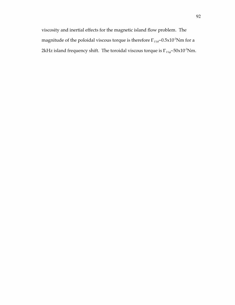
92
viscosity and inertial effects for the magnetic island flow problem. The
magnitude of the poloidal viscous torque is therefore GVSq~0.5x10⁻³Nm for a
2kHz island frequency shift. The toroidal viscous torque is GVSf~50x10-3Nm.
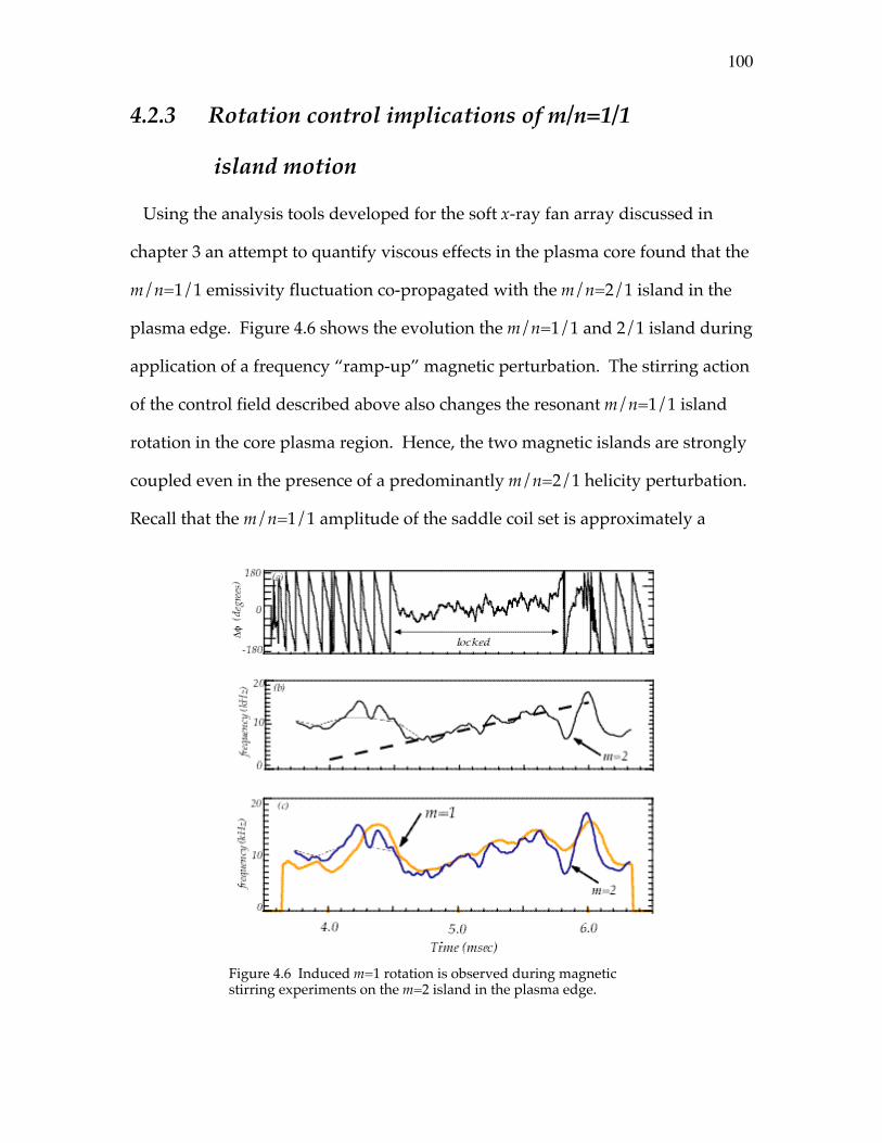
100
4.2.3 Rotation control implications of m/n=1/1
island motion
Using the analysis tools developed for the soft x-ray fan array discussed in
chapter 3 an attempt to quantify viscous effects in the plasma core found that the
m/n=1/1 emissivity fluctuation co-propagated with the m/n=2/1 island in the
plasma edge. Figure 4.6 shows the evolution the m/n=1/1 and 2/1 island during
application of a frequency “ramp-up” magnetic perturbation. The stirring action
of the control field described above also changes the resonant m/n=1/1 island
rotation in the core plasma region. Hence, the two magnetic islands are strongly
coupled even in the presence of a predominantly m/n=2/1 helicity perturbation.
Recall that the m/n=1/1 amplitude of the saddle coil set is approximately a
Figure 4.6 Induced m=1 rotation is observed during magneticstirring experiments on the m=2 island in the plasma edge.
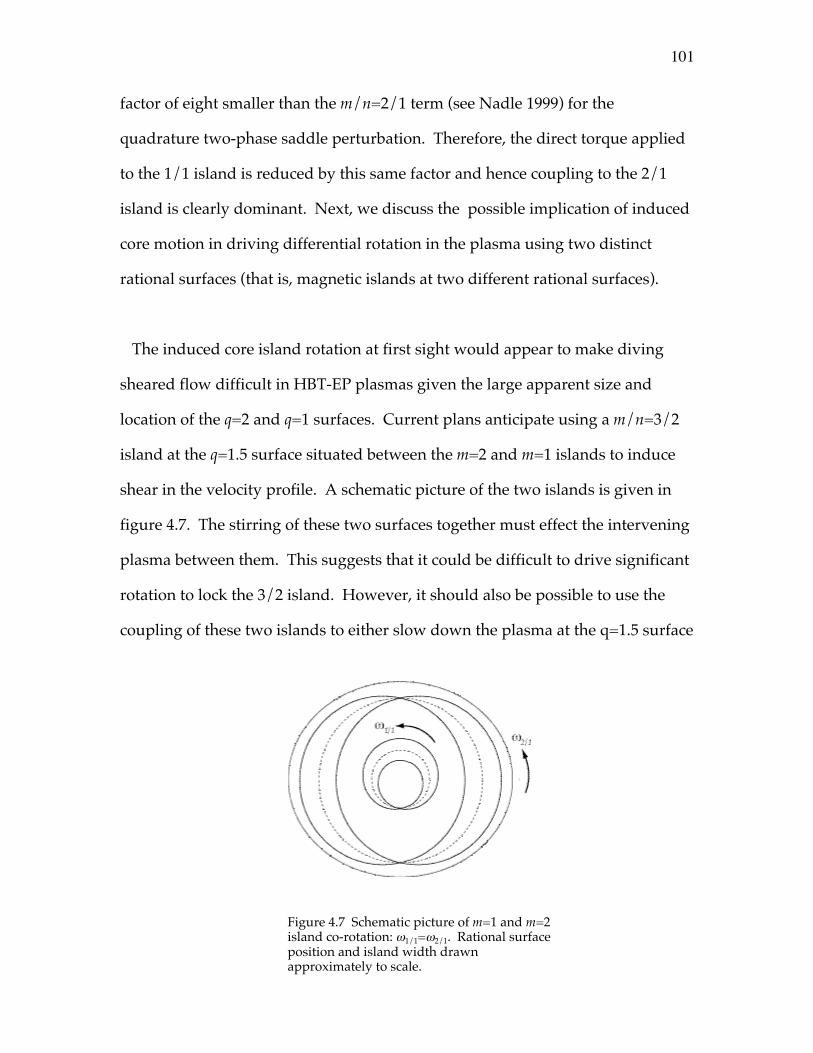
101
factor of eight smaller than the m/n=2/1 term (see Nadle 1999) for the
quadrature two-phase saddle perturbation. Therefore, the direct torque applied
to the 1/1 island is reduced by this same factor and hence coupling to the 2/1
island is clearly dominant. Next, we discuss the possible implication of induced
core motion in driving differential rotation in the plasma using two distinct
rational surfaces (that is, magnetic islands at two different rational surfaces).
The induced core island rotation at first sight would appear to make diving
sheared flow difficult in HBT-EP plasmas given the large apparent size and
location of the q=2 and q=1 surfaces. Current plans anticipate using a m/n=3/2
island at the q=1.5 surface situated between the m=2 and m=1 islands to induce
shear in the velocity profile. A schematic picture of the two islands is given in
figure 4.7. The stirring of these two surfaces together must effect the intervening
plasma between them. This suggests that it could be difficult to drive significant
rotation to lock the 3/2 island. However, it should also be possible to use the
coupling of these two islands to either slow down the plasma at the q=1.5 surface
Figure 4.7 Schematic picture of m=1 and m=2island co-rotation: w1/1=w2/1. Rational surfaceposition and island width drawnapproximately to scale.
102
if a static perturbation is to be applied. Also, the surface could be sped up so that
a rotating field would couple significant torque to the 3/2 magnetic island. Note
that when naturally occurring 3/2 modes exist in typical HBT-EP plasmas they
do propagate at twice the typical n=1 mode rotation rate (Ivers et al 1995). This
implies a typical frequency of ~20kHz. Once a 3/2 mode has been created the
2/1 surface could then be driven in an appropriate way to possibly drive shear
between the two magnetic islands. These issues can obviously only be clarified
with further resonant magnetic perturbation experiments on HBT-EP.

97
4.2.2 Torque balance summary: poloidal flow damping
Here we collect the estimates of the previous sections. The main observation to
be made is that the preceding torque balance is consistent when poloidal flow
damping is taken into account.
The evolution equation for deviation in island velocity for the torodial direction
is found by considering the projection of the momentum equation in that
direction. Thus for the toroidal torque,
rdDvz
dt= z ⋅
rj ¥
rb -
∂p∂z
+ — ⋅ rn—Dvz( ) . (4.24)
Integrating this equation, with ∂p/∂z ª 0 , over the island region yields the total
torque balance equation for the evolution of the deviation in island velocity
whose individual terms have been discussed in the preceding sections
(Fitzpatrick 1994, Hegna et al 1998),
ddt
If Dwf( ) @ If
dDwf
dt= TVSf + TEMf (4.25)
for the toroidal frequency evolution, and
ddt
Iq Dwq( ) @ Iq
dDwq
dt= TVSq + TEMq (4.26)
for the poloidal frequency evolution. Using the above estimated torque
magnitudes for the poloidal and toroidal terms, the perpendicular torque at the
mode rational surface is calculated from,
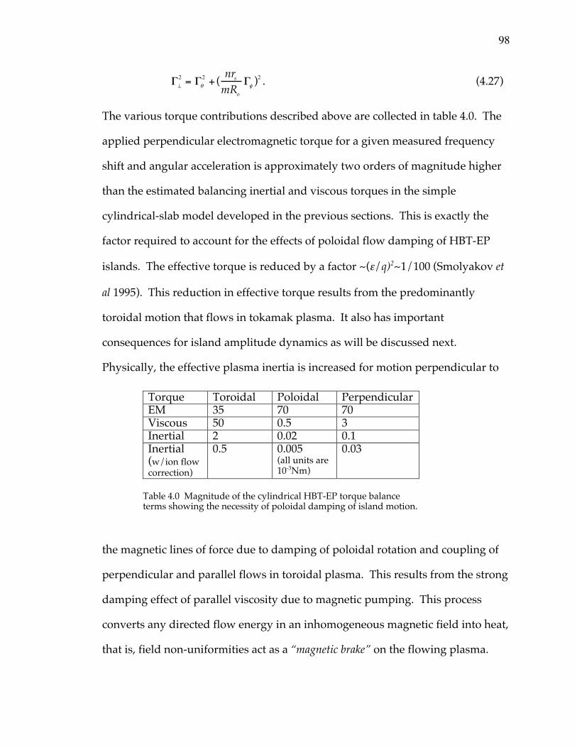
98
G^
2 = Gq
2 + (nrs
mRo
Gf )2 . (4.27)
The various torque contributions described above are collected in table 4.0. The
applied perpendicular electromagnetic torque for a given measured frequency
shift and angular acceleration is approximately two orders of magnitude higher
than the estimated balancing inertial and viscous torques in the simple
cylindrical-slab model developed in the previous sections. This is exactly the
factor required to account for the effects of poloidal flow damping of HBT-EP
islands. The effective torque is reduced by a factor ~(e/q)2~1/100 (Smolyakov et
al 1995). This reduction in effective torque results from the predominantly
toroidal motion that flows in tokamak plasma. It also has important
consequences for island amplitude dynamics as will be discussed next.
Physically, the effective plasma inertia is increased for motion perpendicular to
the magnetic lines of force due to damping of poloidal rotation and coupling of
perpendicular and parallel flows in toroidal plasma. This results from the strong
damping effect of parallel viscosity due to magnetic pumping. This process
converts any directed flow energy in an inhomogeneous magnetic field into heat,
that is, field non-uniformities act as a “magnetic brake” on the flowing plasma.
Torque Toroidal Poloidal PerpendicularEM 35 70 70Viscous 50 0.5 3Inertial 2 0.02 0.1Inertial(w/ion flowcorrection)
0.5 0.005(all units are10-3Nm)
0.03
Table 4.0 Magnitude of the cylindrical HBT-EP torque balanceterms showing the necessity of poloidal damping of island motion.

99
This means that the any attempt to drive poloial flow actually results in a driven
parallel flow that exactly cancels any poloidal motion and results in a net
toroidal flow. The fact that the required electromagnetic torque is consistent
with predominantly toroidal island motion supports the inclusion of this
important physics for HBT-EP magnetic islands.
103
4.3 Magnetic island amplitude dynamics
In this section we study the effect of the rotation control experiments on
magnetic island width or amplitude. From the perspective of the introductory
discussion of chapter one, the possibility of other contributions dependent upon
island rotation to the evolution equation for the island width is studied.
Experimentally, a correlation between the island frequency modulation due to
this perturbation and the damping and growth of island size is observed. A
frequency dependent amplitude term was found essential in modeling of active
control experiments on HBT-EP (Navratil et al 1998, Nadle 2000). The new
observation presented here is that it is experimentally found that acceleration
away from the island natural rotation rate leads to island amplitude growth
whereas deceleration below the natural island speed gives rise to damping of
island size.
A brief discussion of the basic physics of the inertial or ion polarization
contribution to the modified Rutherford island width evolution equation and its
characteristic magnitude for HBT-EP plasmas is discussed. Next, the island
growth and damping asymmetry observed in acceleration and deceleration of
HBT-EP islands in response to these rotating control fields is discussed as to
whether the sign of the polarization current contribution to Rutherford’s
equation is stabilizing or destabilizing. The observed correlation of acceleration
with island growth and deceleration with island suppression is found o be
consistent with a destabilizing ion polarization current contribution to magnetic

104
island width evolution. This observation constitutes the first experimental
evidence obtained as to the destabilizing nature of ion inertia to magnetic island
growth. The issue as to whether these currents contribute in a stabilizing or
destabilizing manner to magnetic island dynamics is a crucial current question in
the physics of magnetic island formation in toroidal plasmas. The stabilizing or
destabilizing effect of the polarization term has important implications for
neoclassical tearing mode threshold levels (La Haye et al 2000) and long pulse b-
limits observed in some advanced tokamak scenarios (Wilson et al 1998). Finally,
it was found that application of perturbations of this type to disruptive target
plasma inhibited the loss of plasma density and core thermal energy. This
simple technique offers a possible method of reducing the impact of sudden
discharge termination due to loss of equilibrium in disruptive plasmas.
4.3.1 Asymmetric island amplitude growth and suppression
Application of a frequency modulated magnetic perturbation that alternates
between a frequency above and below the natural rotation rate of the magnetic
island was first suggested by Kurita and coworkers (1994) as a possible candidate
for island suppression. Kurita, in simulations of rotating viscous plasma, found
Figure 4.7 Example of a frequency modulated saddle coil current that alternatesbetween frequencies above and below the natural island rotation frequency.
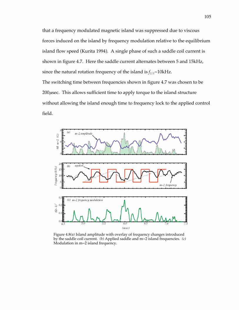
105
that a frequency modulated magnetic island was suppressed due to viscous
forces induced on the island by frequency modulation relative to the equilibrium
island flow speed (Kurita 1994). A single phase of such a saddle coil current is
shown in figure 4.7. Here the saddle current alternates between 5 and 15kHz,
since the natural rotation frequency of the island is f2/1~10kHz.
The switching time between frequencies shown in figure 4.7 was chosen to be
200msec. This allows sufficient time to apply torque to the island structure
without allowing the island enough time to frequency lock to the applied control
field.
Figure 4.8(a) Island amplitude with overlay of frequency changes introducedby the saddle coil current. (b) Applied saddle and m=2 island frequencies. (c)Modulation in m=2 island frequency.
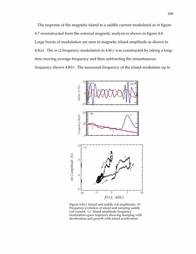
106
The response of the magnetic island to a saddle current modulated as in figure
4.7 reconstructed from the external magnetic analysis is shown in figure 4.8.
Large bursts of modulation are seen in magnetic island amplitude as shown in
4.8(a). The m=2 frequency modulation in 4.8(c) was constructed by taking a long-
time moving average frequency and then subtracting the instantaneous
frequency shown 4.8(b). The measured frequency of the island modulates up to
Figure 4.8(a) Island and saddle coil amplitudes. (b)Frequency evolution of island and ramping saddlecoil current. (c) Island amplitude-frequencymodulation space trajectory showing damping withdeceleration and growth with island acceleration.
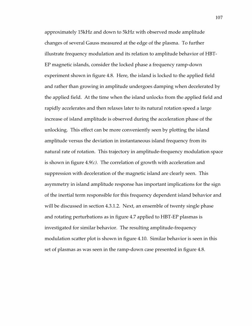
107
approximately 15kHz and down to 5kHz with observed mode amplitude
changes of several Gauss measured at the edge of the plasma. To further
illustrate frequency modulation and its relation to amplitude behavior of HBT-
EP magnetic islands, consider the locked phase a frequency ramp-down
experiment shown in figure 4.8. Here, the island is locked to the applied field
and rather than growing in amplitude undergoes damping when decelerated by
the applied field. At the time when the island unlocks from the applied field and
rapidly accelerates and then relaxes later to its natural rotation speed a large
increase of island amplitude is observed during the acceleration phase of the
unlocking. This effect can be more conveniently seen by plotting the island
amplitude versus the deviation in instantaneous island frequency from its
natural rate of rotation. This trajectory in amplitude-frequency modulation space
is shown in figure 4.9(c). The correlation of growth with acceleration and
suppression with deceleration of the magnetic island are clearly seen. This
asymmetry in island amplitude response has important implications for the sign
of the inertial term responsible for this frequency dependent island behavior and
will be discussed in section 4.3.1.2. Next, an ensemble of twenty single phase
and rotating perturbations as in figure 4.7 applied to HBT-EP plasmas is
investigated for similar behavior. The resulting amplitude-frequency
modulation scatter plot is shown in figure 4.10. Similar behavior is seen in this
set of plasmas as was seen in the ramp-down case presented in figure 4.8.
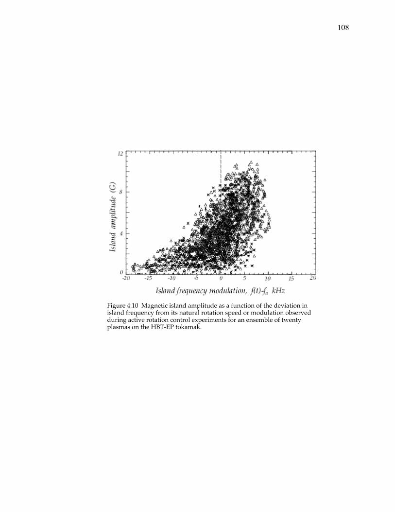
108
Figure 4.10 Magnetic island amplitude as a function of the deviation inisland frequency from its natural rotation speed or modulation observedduring active rotation control experiments for an ensemble of twentyplasmas on the HBT-EP tokamak.
109
4.3.1.1 Ion polarization physics and island rotation
Here a simple heuristic derivation of the ion polarization damping contribution
to the Rutherford equation and estimates of its magnitude for typical HBT-EP
conditions is given. This driven current depends upon the frame of reference of
the ion fluid with respect to the rotating magnetohydrodynamic mode or
magnetic island. For simplicity take the ions to be at rest in the lab frame, this is
a reasonable approximation since measured torodial ion flows are typically ~1
km/sec in HBT-EP (Taylor 2000), and are small compared to typical mode
rotation frequencies. Later, finite ion rotation will be briefly considered.
Take a tearing mode propagating at a frequency, f2/1, in the lab (~ion) frame of
reference. Island rotation induces an electric field through Faraday’s Law in the
ion frame of reference,
— ¥ ˜rE = -
∂˜rb∂t
. (4.20)
The important component for our purpose is in the theta direction and relates the
poloidal field fluctuation of the mode to the induced radial electric field
experienced by the ions. This implies the following relation between mode
angular frequency, mode wave number and amplitude, and the induced
fluctuating radial electric field seen by the ions,
Er =wkj
bq , (4.21)
and the wave vector of the magnetohydrodynamic mode satisfying rk ⋅
rBo = 0 .
110
This formula allows us to estimate the inductive radial electric field. For a
typical HBT-EP tearing mode take the following as typical: bq(rs)=10G,
w=2pf2/1=2p (10kHz), and kj=n/Ro=1/(95cm). This gives a fluctuating electric field
of ~0.6 V/cm. For comparison the equilibrium radial electric field setup on a
particle confinement time scale due to ambipolar diffusion should be of order the
electron temperature in the plasma divided by the minor radius: Ero~Teo/a.
Using Teo=100V and a=13cm, gives an equilibrium field of approximately 7 to 8
V/cm. Thus the fluctuating field induced in the ion frame due to island rotation
is roughly of order ~10% of the equilibrium radial electric field given the simple
estimates here. Next, we estimate the effective force on the ion fluid due to this
fluctuating perturbed electric field.
The dominate polarization drift term comes from crossing the perpendicular
force felt by the ions with the equilibrium magnetic field. To calculate this force,
rF = mi
dr
V^
dt, (4.22)
where the perpendicular velocity is,
rV =
rV - V//b . (4.23)
Using this expression in the perpendicular force and noting that rV is simply the
rE ¥
rB velocity driven by the rotating island, therefore
rF = mi
ddt
rVr
E¥rB - V//b( ) . (4.24)
Writing out the terms in parenthesis for the rE ¥
rB and parallel velocities yields,
111
rF = mi
ddt
ErBoj
Bo2 - V//q
Ê
ËÁ
ˆ
¯˜q +
ErBoq
Bo2 - V//j
Ê
ËÁ
ˆ
¯˜ j
ÏÌÓ
¸˝˛
. (4.25)
Where the only time dependence considered for simplicity is contained in the
fluctuating radial electric field. Since parallel flow is, by definition, along the
magnetic field direction we can write,
rV// =
V//
Bo
Boqq + Bojj( ) , (4.26)
and,
rV// = V//qq + V//jj . (4.27)
Equating components of the two forms above we note that the poloidal and
torodial components of the parallel flow must of course satisfy,
V//j = V//q
Boj
Boq
. (4.28)
If parallel viscosity is the dominate dissipation mechanism, one expects the
poloidal flow in the plasma to be damped to zero on an ion-ion collision time
scale due to magnetic pumping. This is the usual assumption in derivations of
the ion polarization term in the literature. If the total poloidal flow is set to zero
in the expression for the perpendicular force, this allows us to solve for the
poloidal component of the parallel flow,
V//q =ErBoj
Bo2 ª
Er
Boj
. (4.29)
The poloidal component of the parallel flow then fixes the torodial component of
the parallel flow as well,
V//j = V//q
Boj
Boq
ªEr
Boq
. (4.30)
112
Therefore the perpendicular force becomes,
rF = mi
ddt
ErBoq
Bo2 -
Er
Boq
Ê
ËÁ
ˆ
¯˜j , (4.31)
if there is strong poloidal flow damping. This can be further simplified by noting
that the first term in parenthesis is of order ~(e/q)2 smaller than the second term.
Hence,
rF ª -mi
ddt
Er
Boq
Ê
ËÁ
ˆ
¯˜j , (4.32)
or,
F ~ -miwEr
Boq
. (4.33)
How large is this force for HBT-EP conditions? Taking the electric field value of
~0.6V/cm derived above and estimating Boq=e(Boj/q)=208G, with e=12/95, q=2,
Boj=3.3kG, for a f2/1=10kHz mode gives a force of 6.28x10⁻¹⁹ N on an individual
deuteron. This would give rise to a force density ~1mN/cm3 for typical 1013 cm-3
plasma densities. This force can now be inserted into the rF ¥
rB drift to evaluate
the induced polarization current, with Vpol = F /qB .
This gives rise to the following the following radial ion current,
rjpol = qn
rVpol =
minw 2
kjBoq
r (4.34)
This induced polarization current is approximately ~2mA/cm2 for a typical HBT-
EP tearing mode. The electron contribution to the current is smaller by a factor
of the electron to ion mass ratio (~1/1837) and can be neglected. Next, the
parallel current induced by this effectively perpendicular polarization current
113
following into the island is estimated along with the magnitude of the resulting
delta prime contribution of this parallel current to Rutherford’s equation.
The mode rotation induced polarization current flowing into the island region
drives a parallel current to neutralize any charge density build up, — ⋅rj = 0.
The gradient operators near the magnetic island are approximated as
—^ ~∂/∂r ~1/W and —// ~ kqW /Ls . Using this we can write for the magnitude
of the parallel current,
j// =Ls
kqW2
Ê
ËÁ ˆ
¯˜ jpol =
Ls
kqW2
Ê
ËÁ ˆ
¯˜ minw2
kjBoq
. (4.35)
It is this current which affects the tearing mode amplitude through its
contribution to delta prime in the Rutherford evolution equation. Taking typical
HBT-EP parameters the parallel current is calculated to be of order j//~1/3 to
1A/cm2, with Ls (see section 3.4.1) ranging from ~100cm to 300cm for the
magnetic shear scale length, kq=m/rs~2/10cm, and W~3cm. For comparison,
recall that the parallel current flowing in a 3cm island estimated in section 4.2.1.1
estimated from j//(rs ) ~ bq (rs )/ moW is approximately 4A/cm2. Thus, the induced
polarization current is of the correct order of magnitude for the typical HBT-EP
magnetic island size.
Substituting the parallel current from equation 4.35 into the definition of delta
prime for a given perturbed current, which can be written as
¢D =m oLs
Boq
j//
W, (4.36)
114
gives the polarization contribution to delta prime as,
¢D =m oLs
Boq
Ls
kqW3
Ê
ËÁ ˆ
¯˜ minw 2
kj Boq
. (4.37)
Notice that delta prime scales as D’~w2/W3. Collecting terms and rearranging, the
above delta prime can be evaluated using the above estimates to be rs ¢D ª 2 . This
order of magnitude will have a substantial effect on magnetic island size for
HBT-EP conditions. Thus, the order of magnitude of the inertial term in the
island evolution equation is large enough to affect the observed behavior of m=2
islands during magnetic stirring experiments. These effects are large on HBT-EP
due to the relatively large island rotation rate, large saddle coil frequency
modulations along with the low machine poloidal field strength and small island
size in comparison to other tokamaks. For comparison, we estimate the delta
prime contribution using the above formula for an equivalent DIII-D 2/1
magnetic island. For DIII-D we take the following parameters: Ro=1.67m,
a=0.67m, Bf=1.3T, fMHD=1.6kHz (La Haye et al 1992), and use rs=0.8a with
W/rs=0.3. This gives an induced polarization current of jpol=8.5x10⁻³A/cm2,
which is a factor of four times larger than the HBT-EP estimate. This polarization
current then drives a parallel current of magnitude j//=0.15A/cm2, or about three
to ten times smaller then the HBT-EP estimate. Most importantly, this yields a
delta prime contribution for DIII-D of rs ¢D ª 0.1 , which is at least an order of
magnitude smaller than the HBT-EP inertial delta prime estimate. These inertial
term effects can therefore be studied more easily in the smaller HBT-EP
experiment.
4.3.1.2 Asymmetric amplitude response and ion inertia
115
The simple inertial effect considered in the previous section estimated the
magnitude of the polarization term in the Rutherford island width evolution
equation for typical HBT-EP magnetic islands. This inertial contribution is of
sufficient magnitude for HBT-EP magnetic islands that observed changes typical
in toroidal island motion induced during rotation control experiments can cause
a large influx of polarization current. The inclusion of poloidal flow damping
and its concomitant ion mass renormalization due to coupling of transverse and
longitudinal plasma flow across and along the magnetic field can be viewed as a
simple rescaling of the Alfven velocity of the plasma to the poloidal Alfven
velocity, VA2 Æ VAq
2 = VA2rs
2 /q2R 2 (Smolyakov et al 1996). These terms are crucial in
setting the appropriate scale of inertial effects on HBT-EP.
The inclusion of poloidal flow damping and resultant large increase of the
inertial contribution to Rutherford’s equation are supported by the empirical
torque balance developed in section 4.2.1 for typical HBT-EP island locking
behavior. There the order of magnitude of any induced island frequency change
was consistent with predominantly toroidal motion driven by the external
control field torque. Any induced poloidal motion appears to be small in
comparison. This is also consistent with negligible poloidal flow changes
measured using a Mach probe apparatus during these experiments (Taylor 2000).
Next, we consider the sign of the inertial contribution to the island width
equation given the experimental observation of section 4.3.1 that strongly
accelerated islands grow in amplitude while those that are decelerated are
116
suppressed in amplitude. What does this observation imply about the sign of the
polarization term in Rutherford’s equation.
The effects of inertia and viscosity on island growth and damping have become
a source of recent theoretical controversy. In a resistive magnetohydrodynamic
context, initial work suggested that ion inertia had a stabilizing effect of island
size when the rotation of the island or rational surface is perturbed away from its
natural rate (Fitzpatrick and Hender 1991). Later inclusion of finite Larmor
radius and diamagnetic effects (Smolyakov 1993, Smolyakov et al 1995) and long
mean free path physics (Wilson et al 1996) opened a window of instability. The
instability window is dependent upon island, rE ¥
rB and diamagnetic flow
velocities at the position of the magnetic island, but did not change the overall
sign of the inertial term from stabilizing to destabilizing. Waelbroek and
Fitzpatrick (1997) have recently pointed out that inertia can lead to a
destabilizing effect on island width due to essentially a Kelvin-Helmholtz type
instability. Recently, work by Mikhailovskii and coworkers (Mikhailovskii(a) et
al 2000, Mikhailovskii(b) et al 2000) have confirmed and extended the original
result of Waelbroek and Fitzpatrick. Further theoretical and experimental work
will hopefully further clarify these important effects on magnetic island width
dynamics in toroidal plasma. Importantly, the effect of these “separatrix-
corrections” to the polarization delta prime term change its sign while leaving the
magnitude of the effect essentially the same (Fitzpatrick and Waelbroek 2000) in
the resistive magnetohydrodynamic limit. Thus, we have some confidence that
the estimated magnitude of ¢D pol given in section 4.3.1.1 is insensitive to the
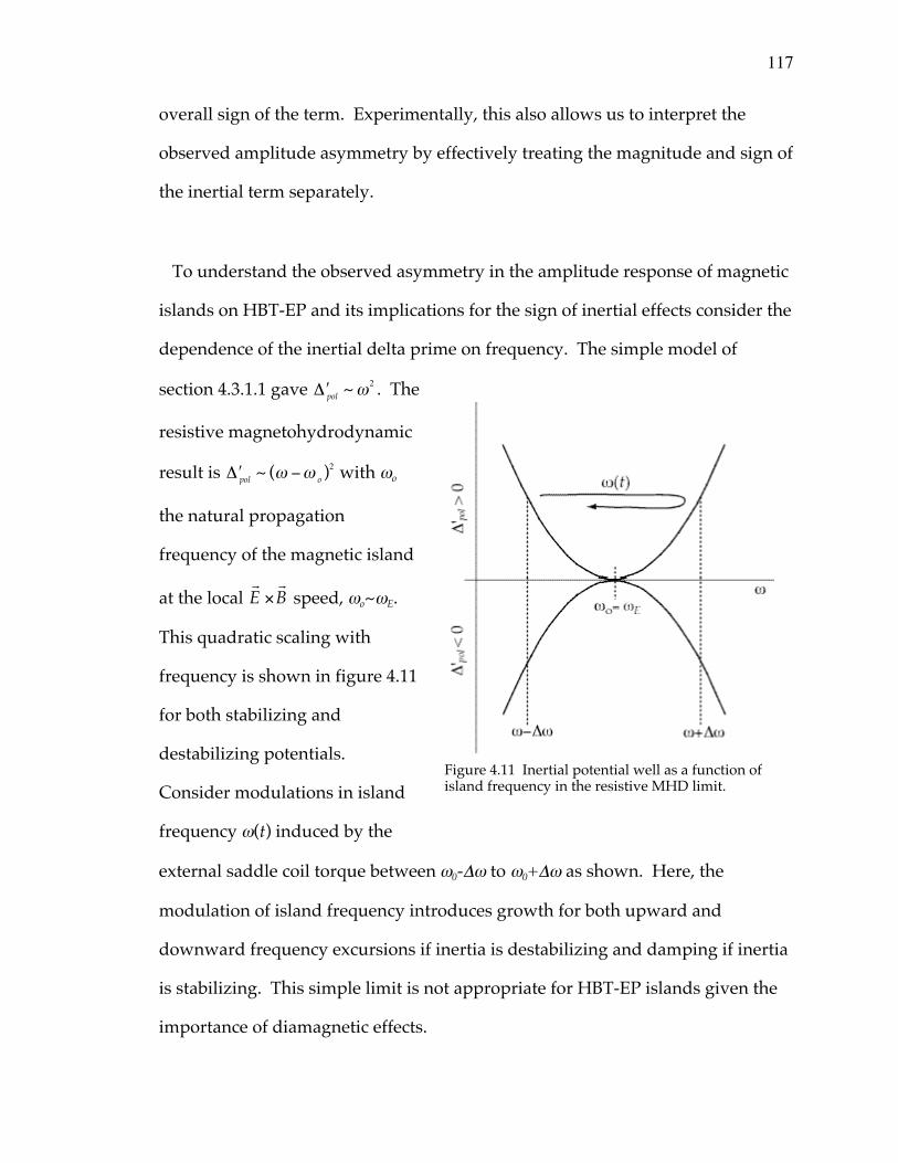
117
overall sign of the term. Experimentally, this also allows us to interpret the
observed amplitude asymmetry by effectively treating the magnitude and sign of
the inertial term separately.
To understand the observed asymmetry in the amplitude response of magnetic
islands on HBT-EP and its implications for the sign of inertial effects consider the
dependence of the inertial delta prime on frequency. The simple model of
section 4.3.1.1 gave ¢D pol ~ w2 . The
resistive magnetohydrodynamic
result is ¢D pol ~ (w -w o )2 with wo
the natural propagation
frequency of the magnetic island
at the local rE ¥
rB speed, wo~wE.
This quadratic scaling with
frequency is shown in figure 4.11
for both stabilizing and
destabilizing potentials.
Consider modulations in island
frequency w(t) induced by the
external saddle coil torque between w0-Dw to w0+Dw as shown. Here, the
modulation of island frequency introduces growth for both upward and
downward frequency excursions if inertia is destabilizing and damping if inertia
is stabilizing. This simple limit is not appropriate for HBT-EP islands given the
importance of diamagnetic effects.
Figure 4.11 Inertial potential well as a function ofisland frequency in the resistive MHD limit.
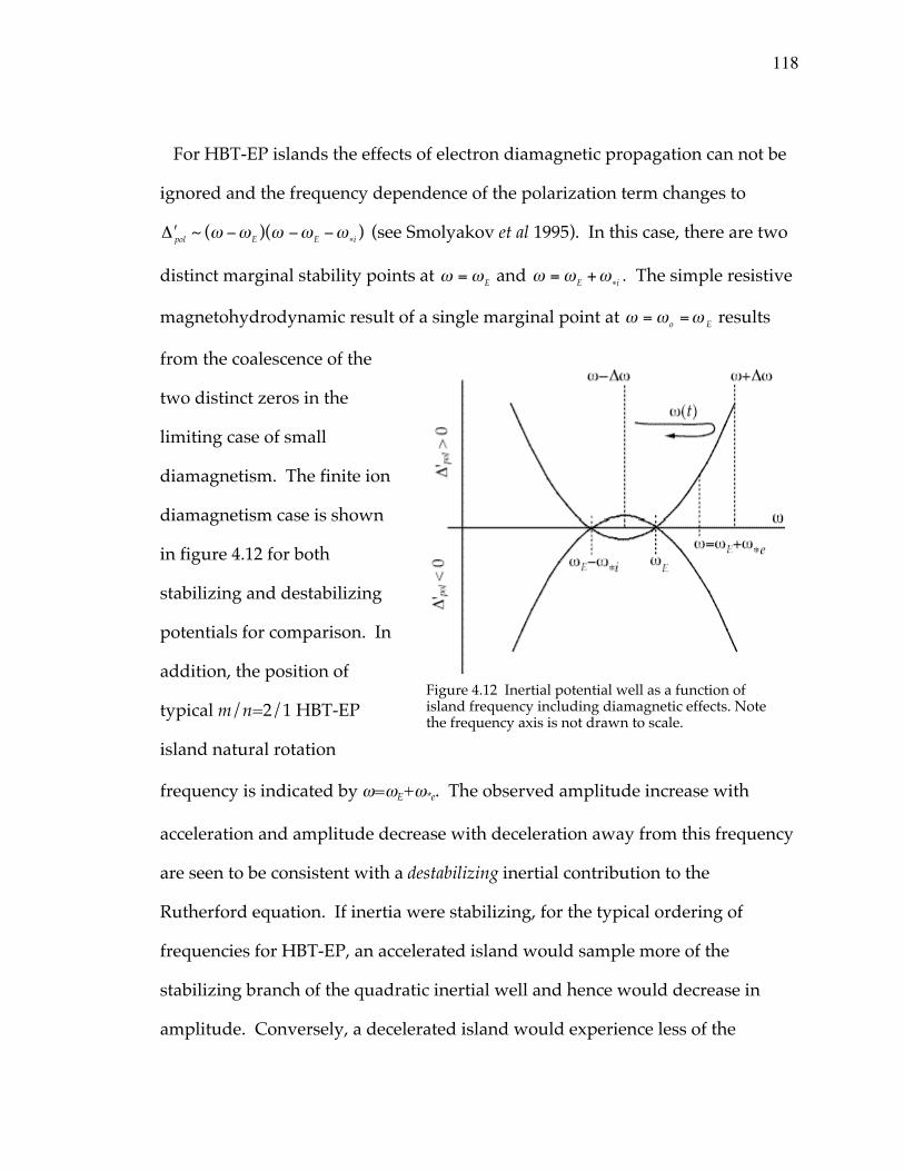
118
For HBT-EP islands the effects of electron diamagnetic propagation can not be
ignored and the frequency dependence of the polarization term changes to
¢D pol ~ (w -wE )(w -wE -w*i ) (see Smolyakov et al 1995). In this case, there are two
distinct marginal stability points at w = wE and w = wE +w*i . The simple resistive
magnetohydrodynamic result of a single marginal point at w = wo =w E results
from the coalescence of the
two distinct zeros in the
limiting case of small
diamagnetism. The finite ion
diamagnetism case is shown
in figure 4.12 for both
stabilizing and destabilizing
potentials for comparison. In
addition, the position of
typical m/n=2/1 HBT-EP
island natural rotation
frequency is indicated by w=wE+w*e. The observed amplitude increase with
acceleration and amplitude decrease with deceleration away from this frequency
are seen to be consistent with a destabilizing inertial contribution to the
Rutherford equation. If inertia were stabilizing, for the typical ordering of
frequencies for HBT-EP, an accelerated island would sample more of the
stabilizing branch of the quadratic inertial well and hence would decrease in
amplitude. Conversely, a decelerated island would experience less of the
Figure 4.12 Inertial potential well as a function ofisland frequency including diamagnetic effects. Notethe frequency axis is not drawn to scale.
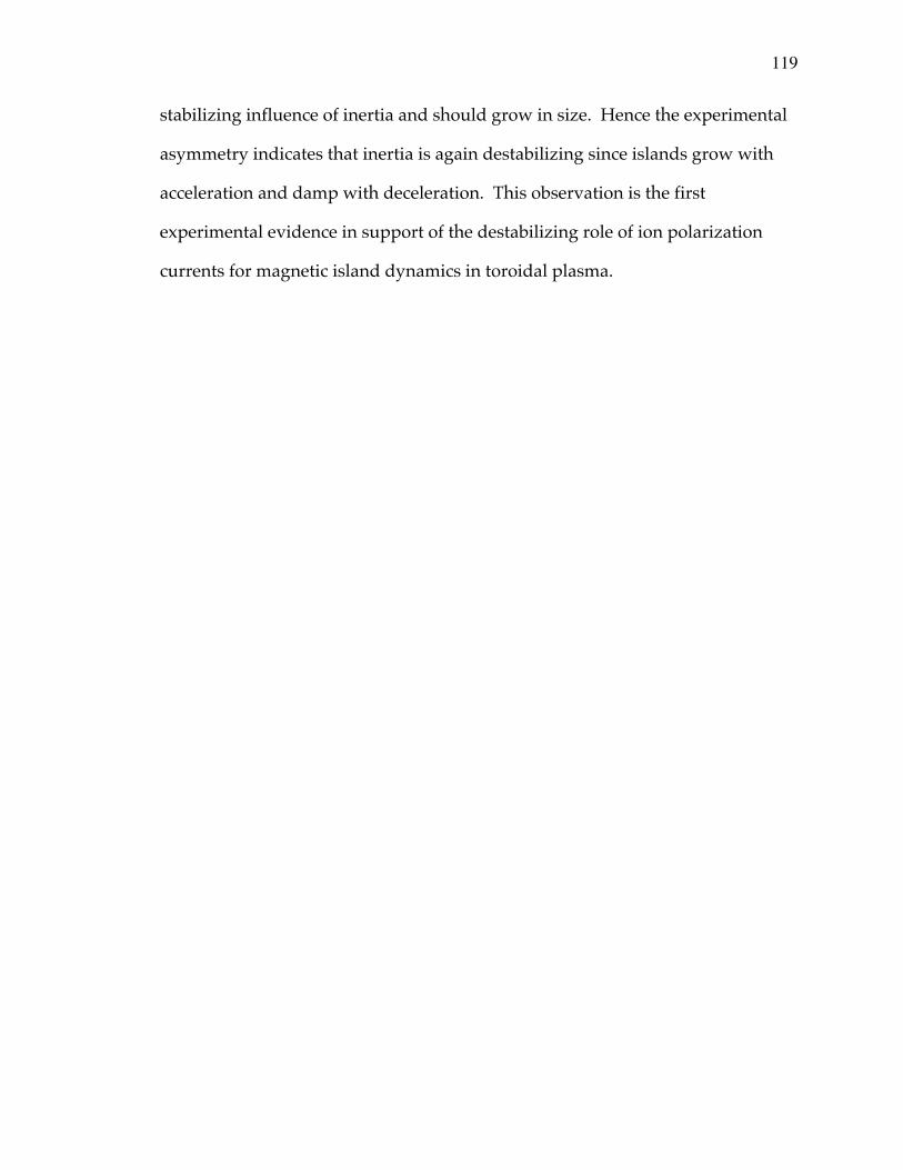
119
stabilizing influence of inertia and should grow in size. Hence the experimental
asymmetry indicates that inertia is again destabilizing since islands grow with
acceleration and damp with deceleration. This observation is the first
experimental evidence in support of the destabilizing role of ion polarization
currents for magnetic island dynamics in toroidal plasma.
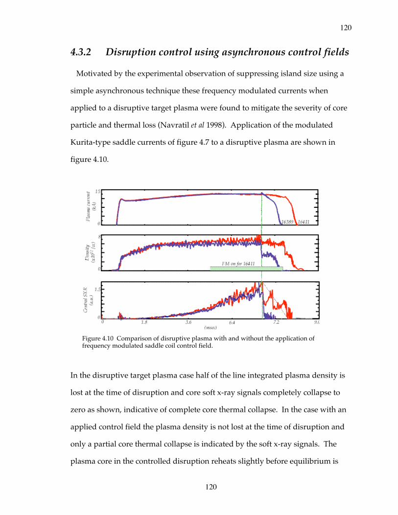
120
120
4.3.2 Disruption control using asynchronous control fields
Motivated by the experimental observation of suppressing island size using a
simple asynchronous technique these frequency modulated currents when
applied to a disruptive target plasma were found to mitigate the severity of core
particle and thermal loss (Navratil et al 1998). Application of the modulated
Kurita-type saddle currents of figure 4.7 to a disruptive plasma are shown in
figure 4.10.
In the disruptive target plasma case half of the line integrated plasma density is
lost at the time of disruption and core soft x-ray signals completely collapse to
zero as shown, indicative of complete core thermal collapse. In the case with an
applied control field the plasma density is not lost at the time of disruption and
only a partial core thermal collapse is indicated by the soft x-ray signals. The
plasma core in the controlled disruption reheats slightly before equilibrium is
Figure 4.10 Comparison of disruptive plasma with and without the application offrequency modulated saddle coil control field.
121
121
lost due to the vertical field force pushing the plasma toward the inner vacuum
chamber wall. This simple asynchronous technique offers the possibility of
ameliorating the consequences of sudden plasma loss due to disruptive
phenomena and its harmful attendant effects on tokamak devices.
122
5.0 Summary and conclusions
Magnetic island rotation frequency and amplitude dynamics have been studied
on the HBT-EP tokamak using a compact saddle coil set able to apply perturbing
electromagnetic torque to pre-existing m/n=2/1 islands.
Rotation control and torque balance
Rotation control of these islands was demonstrated over a frequency range of
~5 to 15kHz. The magnetic stirring of the island was studied by constructing a
detailed torque balance near the resonant q=2 surface. A simple current density
and q-profile was constructed from internal emissivity fluctuation measurements
to aid in estimation of m/n=2/1 island width, rational surface location, and
magnetic shear. Using these tools, the measured electromagnetic locking torque
is found to be consistent with toroidally driven island motion by the external
field. The observed electromagnetic locking torque and induced toroidal island
rotation point to the importance of poloidal flow damping in describing the
physics of HBT-EP magnetic islands. Inclusion of flow damping is also crucial in
estimating the magnitude of inertial effects on island size. Observation and
analysis of m/n=1/1 island induced motion in the plasma core brought about by
the external stirring perturbation was observed and implications of the induced
motion for differential rotation studies was explicated. The 1/1 island motion
was found to be strongly coupled to the 2/1 island in the edge plasma for both
natural propagation and during active control experiments of the 2/1 island.
123
Magnetic island rotational damping and growth
Magnetic island amplitude dynamics were also examined. Here, using novel
frequency modulated control current techniques, a regime of magnetic island
suppression and growth has been discovered. Island size is observed to damp
when magnetic island frequency is decelerated from its natural rotation rate by
the applied magnetic perturbation. It is also observed that acceleration of the
island structure induces growth of the pre-existing fluctuation. Simple estimates
of the effect of inertia on magnetic island size have been developed and with the
inclusion of flow damping yield the correct order of magnitude to account for the
observed amplitude changes. The observed asymmetry in acceleration and
deceleration with island growth and damping has been shown to be consistent
with a destabilizing inertial contribution to the island width evolution equation.
This is the first reported experimental evidence to indicate the destabilizing
nature of ion polarization currents in the dynamics of magnetic islands, with
important consequences, for example, in the role of inertia in error field mode
locking penetration levels, threshold characteristics of neoclassical islands, and
scaling of the long pulse tokamak b-limit.
Disruption control
Finally, observation of a simple asynchronous control method to alleviate the
effects of disruptive plasma loss has been developed and applied to HBT-EP
plasmas. The loss of plasma density and core thermal energy was inhibited by
application of these control perturbations. It is conjectured that this is due to the
maintenance of outer flux surface integrity. The use of such a control technique
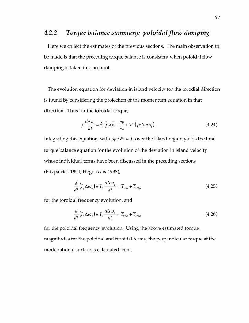
97
4.2.2 Torque balance summary: poloidal flow damping
Here we collect the estimates of the previous sections. The main observation to
be made is that the preceding torque balance is consistent when poloidal flow
damping is taken into account.
The evolution equation for deviation in island velocity for the torodial direction
is found by considering the projection of the momentum equation in that
direction. Thus for the toroidal torque,
rdDvz
dt= z ⋅
rj ¥
rb -
∂p∂z
+ — ⋅ rn—Dvz( ) . (4.24)
Integrating this equation, with ∂p/∂z ª 0 , over the island region yields the total
torque balance equation for the evolution of the deviation in island velocity
whose individual terms have been discussed in the preceding sections
(Fitzpatrick 1994, Hegna et al 1998),
ddt
If Dwf( ) @ If
dDwf
dt= TVSf + TEMf (4.25)
for the toroidal frequency evolution, and
ddt
Iq Dwq( ) @ Iq
dDwq
dt= TVSq + TEMq (4.26)
for the poloidal frequency evolution. Using the above estimated torque
magnitudes for the poloidal and toroidal terms, the perpendicular torque at the
mode rational surface is calculated from,

98
G^
2 = Gq
2 + (nrs
mRo
Gf )2 . (4.27)
The various torque contributions described above are collected in table 4.0. The
applied perpendicular electromagnetic torque for a given measured frequency
shift and angular acceleration is approximately two orders of magnitude higher
than the estimated balancing inertial and viscous torques in the simple
cylindrical-slab model developed in the previous sections. This is exactly the
factor required to account for the effects of poloidal flow damping of HBT-EP
islands. The effective torque is reduced by a factor ~(e/q)2~1/100 (Smolyakov et
al 1995). This reduction in effective torque results from the predominantly
toroidal motion that flows in tokamak plasma. It also has important
consequences for island amplitude dynamics as will be discussed next.
Physically, the effective plasma inertia is increased for motion perpendicular to
the magnetic lines of force due to damping of poloidal rotation and coupling of
perpendicular and parallel flows in toroidal plasma. This results from the strong
damping effect of parallel viscosity due to magnetic pumping. This process
converts any directed flow energy in an inhomogeneous magnetic field into heat,
that is, field non-uniformities act as a “magnetic brake” on the flowing plasma.
Torque Toroidal Poloidal PerpendicularEM 35 70 70Viscous 50 0.5 3Inertial 2 0.02 0.1Inertial(w/ion flowcorrection)
0.5 0.005(all units are10-3Nm)
0.03
Table 4.0 Magnitude of the cylindrical HBT-EP torque balanceterms showing the necessity of poloidal damping of island motion.

99
This means that the any attempt to drive poloial flow actually results in a driven
parallel flow that exactly cancels any poloidal motion and results in a net
toroidal flow. The fact that the required electromagnetic torque is consistent
with predominantly toroidal island motion supports the inclusion of this
important physics for HBT-EP magnetic islands.

124
to limit device damage during abrupt plasma termination due to disruptive
phenomena offers a simple method for mitigating device damage. Knowledge
gained during this study of magnetic island and plasma dynamical behavior
induced by rotating magnetic perturbations hopefully offers insight and possible
solution to some of the many challenges that we encounter in trying bring about
the promise of fusion energy here on earth.
125
ReferencesArfken, G., (1985), Mathematical methods for physicists, Academic Press, 3rd Ed., pg. 890.
Arsenin, V. V., L. I. Artemenkov, N. V. Ivanov, et al, (1978) “Feedback stabilization of kink instability in the TO-1 tokamk,” in Plasma Physics and Controlled Nuclear Fusion Research, (IAEA 1999), Vol. 2, 197.
Aubry, N., R. Guyonnet, R. Lima, (1991), “Spatiotemporal analysis of complex signals: theory and applications,” Jour. Stat. Phys., Vol. 64, Nos. 3/4, 683.
Aubry, N., F. Carbone, R. Lima, and S. Slimani, (1994), “Wave propagation phenomena from a spatiotemporal viewpoint: resonances and bifurcations,” Jour. Stat. Phys., Vol. 76, Nos. 3/4, 1005.
Aubry, N. and R. Lima, (1995), “Spatio-temporal symmetries,” Jour. Stat. Phys., Vol. 64, Nos. 3/4, 683.
Bagdasarov, A. A., V. F. Denisov, D. P. Ivanov, et al, (1982), “Investigation of transposrt and diruptions in the T-7 tokamak by poloidal field perturbation,” in Plasma Physics and Controlled Nuclear Fusion Research, (IAEA 1983), Vol. 1, 281.
Bateman, G., (1978), MHD instabilities, MIT Press, pg. 197.
Bekefi, G., (1966), Radiation processes in plasmas, John Wiley and Sons, Inc., pg. 131.
Bickerton, R. J., (1997), “Magnetic turbulence and the transport of energy and particles in tokamaks,” Plasma Physics and Cont. Fusion, Vol. 39, 339.
Bol, K., J. L. Cechi, C. C. Daughney, et al, (1974), “Experiments on the Adiabatic Toroidal Compressor,” in Plasma Physics and Controlled Nuclear Fusion Research, (IAEA 1975), Vol. 1, 83.
Boozer, A. H., (1983), “Evaluation of the structure of ergodic fields,” Physics of Fluids B, 26, (5), 1288.
Boozer, A. H., (1985), “Magnetic field line Hamiltonian,” PPPL Report 2094R.
Boozer, A. H., (1992), “Plasma confinement,” Encyclopedia of Physical Science and Technology, Academic Press, Vol. 13.
Boozer, A. H., (1996), “Shielding of resonant magnetic perturbations by rotation,” Physics of Plasmas, Vol. 3, No. 12, 4620.
Braginskii, S. I., (1965), “Transport processes in a plasma,” in Reviews of Plasma Physics, Vol. 1, M.A. Leontovich, Ed., 205.
Callen, J. D. and G. L. Jahns, (1977), “Experimental measurement of electron heat diffusivity in a tokamak,” Phys. Rev. Lett., Vol. 38, No. 9, 491.
Callen, J. D., (1987), “Magnetic island charateristics,” in Nuclear Engineering & Engineering Physics 903 Lecture Notes, University of Wisconsin-Madison.
Callen, J. D., (1987), “Models of plasma confinement and heating in tokamaks,” University of Wisconsin-Madison, UWPR 89-2.
Cary, J. R. and R. G. Littlejohn, (1983), “Noncanonical Hamiltonain mechanics and its application to magnetic field line flow,” Annals of Physics, 151, 1-34, 1.
126
Cates, C., M. Shilov, M. E. Mauel, et al, (2000), “Suppression of resistive wall instabilities with distributed, independently controlled, active feedback coils,” Physics of Plasmas, Vol. 7, No. 8, 3133.
Craven, W. A., (1996), “Resonant External Magnetic Perturbations on the Texas Experimental Tokamak,” Ph.D. Thesis, University of Texas at Austin, FRCR #489.
Den Hartog, D. J., (1996) “Controlling mode and plasma rotation in MST with a rotating magnetic perturbation,” Workshop on Feedback Stabilization of MHD Instabilities, Princeton Plasma physics Laboratory, December 11-13, 1996.
deVries, P. C., G. Waidmann, A. Kramer-Fleckner, et al., (1997), “Temperature profile perturbations due to magnetic islands in TEXTOR,” Plasma Physics and Cont. Fusion, 39, 439.
Dubois, M. A., D. A. Marty, A. Pochelon, (1980), “Method of cartography of q=1 islands during sawtooth activity in tokamaks,” Nuclear Fusion, Vol. 20, No. 11.
Dubois, M. A., A. L. Pecquet, C. Reverdin, (1983), “Internal disruptions in the TFR tokamak: a phenomenological analysis,” Nuclear Fusion, Vol. 23, No. 2.
Dudok de Wit, T., A. L. Pecquet, J. C. Vallet, and R. Lima, (1994), “The biorthogonaldecompostion as a tool for investigating fluctuations in plasmas,” Physics of Plasmas, 1, (10) 3288.
Dudok de Wit, T., (1995), “Enhancement of multichannel data in plasma physics by biorthogonal decomposition,” Plasma Physics and Cont. Fusion, Vol. 37, 117.
Dudok de Wit, T., M. Erba, M. Mattioli, J. L. Segui, (1998), “Self-consistent removal of sawtooth oscillations from transient plasma data by generalized singular value decompostion,” Physicsof Plasmas, 5, (5) 1360.
Eisner, E. C., (1998), “The effects of wall coverage, symmetry, and plasma-wall separation on the stability of tokamak plasmas,” Ph. D. Thesis, Columbia University Plasma Physics Laboratory Report No. 136.
Finken H. K., (2000), “Perturbation field penetration into the TEXTOR tokamak and the resulting torque,” Nuclear Fusion, Vol. 39, No. 6, 707.
Fitzpatrick, R., and T. C. Hender, (1991), “The interaction of resonant magnetic perturbations with rotating plasmas,” Physics of Fluids B, 3, (3), 644.
Fitzpatrick, R., (1993), “Interaction of tearing modes with external structures in cylindrical geometry,” Nuclear Fusion, Vol. 33 No. 7, 1049.
Fitzpatrick, R., (1995), “Helical temperature perturbations associated with tearing modes in tokamaks,” Physics of Plasmas, 2, (3) 825.
Friedberg, J. P., (1987), Ideal magnetohydodynamics, Plenum Press, pg. 6.
Fowler, T. K., (1999), “Nulear power – fusion,” Rev. Mod. Phys., Vol. 71, No. 2, S456.
Furth, H. P., J. Killeen and M. N. Rosenbluth, (1963), “Finite-resistivity instabilites of a sheet pinch,” Physics of Fluids, 6, (4), 459.
127
Garofalo, A. M. V., (1997), “Measurement and interpretation of eddy currents induced in a segmented conducting wall by MHD instabilites in a tokamak,” Ph. D. Thesis, Columbia University Plasma Physics Laboratory Report No. 130.
Garofalo, A. M., E. Eisner, T. H. Ivers, et al, (1999), “Stabilization of kink instabilites by eddy currents in a segmented wall and comparison with ideal MHD theory,” Nuclear Fusion, Vol. 38, No. 7, 1029.
Gates, D. A., (1993), “Passive stabilization of MHD instabilities at high bN in the HBT-EP tokamak,”Ph. D. Thesis, Columbia University Plasma Physics Laboratory Report No. 127.
Gates, D. A., and T. C. Hender, (1996), “Resistive wall induced forbidden bands of mode rotation frequency on the Compass-D tokamak,” Nuclear Fusion, Vol. 36, No. 3, 273.
Gates, D. A., B. Lloyd, A. W. Morris, et al, (1997), “Neoclassical islands on Compass-D,”Nuclear Fusion, Vol. 37, No. 11, 1593.
Gilmore, R., (1998), “Topological analysis of chaotic dynamical systems,” Rev. Mod. Phys., Vol. 70,No. 4, 1455.
Granetz, R., and P. Smeulders, (1988), “X-ray tomography on JET,” Nuclear Fusion, Vol. 28, No.3, 457.
Hammet, G. and K. McGuire, (1982), “Analysis of Mirnov oscillations on PDX,” PPPL Report 1854.
Hansen, A. K., A. F. Almagri, D. J. Den Hartog, et al, (1998), “Locking of multiple resonant mode structures in the reversed-field pinch,” Physics of Plasmas, Vol. 5, No. 8, 2942.
Hassam, A. B. and R. M. Kulsrud, (1978), “Time evolution of mass flows in a collsional tokamak,” Physics of Fluids B, Vol. 21, No. 12, 2271.
Hawryluk, R. J., (1998), “Results from deuterium-tritium tokamak confinement experiments,” Rev. Mod. Phys., Vol. 70, No. 2, 537.
Hegna, C. C. and J. D. Callen, (1992), “Pressure profiles, resonant Pfirsch-Schluter currents, thermal instabilities, and magnetic island formation,” Physics of Fluids B, Vol. 4, No. 12, 4072.
Hegna, C. C. and J. D. Callen, (1992), “Interaction of bootstrap-current-driven magnetic islands,”Physics of Fluids B, Vol. 4, No. 7, 1855.
Hegna, C. C., (1996), “Nonlinear tearing mode interactions and mode locking in reversed-field pinches,” Physics of Plasmas, Vol. 3, No. 12, 46.
Hegna, C. C., (1997), “The physics of neoclassical magnetohydrodynamic tearing modes,” Physics ofPlasmas, Vol. 5 , No. 5, 1767.
Hender T. C., R. Fitzpatrick, A. W. Morris, et al, (1992), “Effect of resonant magnetic perturbations on Compass-C tokamak discharges,” Nuclear Fusion, Vol. 32, No. 12, 2091.
Hinton, F. L., (1983), “Collisional transport in plasma,” in Handbook of Plasma Physics, Vol. 1, M.N. Rosenbluth and R. Z. Sagdeev, Eds., 147.
Hutchinson, I. H., (1987), Principles of plasma diagnostics, Cambridge University Press, pg. 175.
Ivanov, N. V., and A. M. Kakurin, (1979), “Locking of the kink perturbation frequency in a tokamak,” Sov. J. Plasma Phy., Vol. 5, No. 5, 541.
128
Ivers, T. H., E. Eisner, A. Garofalo, et al, (1994), “Passive and active control of MHD instabilities in the HBT-EP tokamak,” in Plasma Physics and Controlled Nuclear Fusion Research,Barcelona, Spain (IAEA 1995), Vol. 2, 287.
Ivers, T. H., E. Eisner, A. Garofalo, et al, (1996), “Observation of wall stabilization and active control of low-n magnetohydrodynamic instabilities in a tokamak,” Physics of Plasmas, 3, (5) 1926.
Jaenike, R., et al, (1988), “The effect of tearing modes on temperature and density profiles and on perpendicular transport in the WII-A stellarator,” Nuclear Fusion,Vol. 28, No. 10, 1737.
Jahns, G. L., M. Soler, B. V. Waddell, J. D. Callen, H. R. Hicks, (1978), “Internal disruptions in tokamaks,” Nuc Fusion, 18, 5, 609.
Jensen, T. H., and A. W. Leonard, (1991), “Control of rotation velocity profile of tokamaks by application of slow electromagnetic waves,” Physics of Fluids B, Vol. 3, No. 12, 3422.
Jensen, T. H., A. W. Leonard, A. W. Hyatt, (1993), “A simple model for driven islands in tokamaks,” Physics of Fluids B, Vol. 5, No. 4, 1239.
Kadomtsev, B. B., (1975), “Disruptive instabiltiy in tokamaks,” Sov. J. Plasma Phy. 1, 389-91.
Karger, F., H. Wobig, S. Corti, et al, (1974), “Influence of resonant helical fields on tokamak discharges,” in Plasma Physics and Controlled Nuclear Fusion Research, (IAEA 1995), Vol. 1, 207.
Kim J. S., D. H. Edgell, J. M. Greene, E. J. Strait and M. S. Chance, (1999), “MHD mode identification of tokamak plasmas from Mirnov signals,” Plasma Physics and Cont. Fusion, Vol. 41, 1399.
Kobayashi, M., H. Kojima, K. Zhai, et al, (2000), “Frequency dependence of tokamak plasma response to the externally applied rotating helical fields,” Physics of Plasmas, Vol. 7, No. 8,3288.
Kombargi, R., (1997 ), “The influence of a conducting wall on disruptions in HBT-EP,” Ph. D. Thesis, Columbia University Plasma Physics Laboratory Report No. 131.
Kruskal, M. D. and R. M. Kulsrud, (1958), “Equilibirum of a magnetically confined plasma in a toroid,” Physics of Fluids, Vol. 1, No. 4, 265.
Kurita, G., T. Tuda, M. Azumi, et al, (1992), “Effect if an external helical field on a rotating magnetic island,” Nuclear Fusion, Vol. 32, No. 11, 1899.
Landau, L. D. and E. M. Lifshitz, (1987), Fluid mechanics, Pergamon, 2 nd Ed., pg. 14.
LaHaye, R. J., R. Fitzpatrick, T. C. Hender, et al, (1992), “Critical error fields for locked mode instability in tokamaks,” Physics of Fluids B, Vol. 4, No. 7, 2098.
LaHaye, R. J., (1997), “Physics of locked modes in ITER: Error field limits, rotation for obviation, and measurement of field errors,” General Atomics report, GA-A22468.
LaHaye, R. J., R. J. Buttery, S. Guenter, et al, (2000), “Dimensionless scaling of the critical beta for the onset of a neoclassical tearing mode,” Physics of Plasmas, Vol. 7, No. 8, 3349.
Lichtenberg, A. J., (1984), “Stochasticity as the mechanism for the disruptive phase of the m=1 tokamak oscillations,” Nuclear Fusion, Vol. 24, No. 10, 1277.
129
Lichtenberg, A. J. and M. A. Lieberman, (1992), Regular and chaotic dynamics, Springer-Verlag New York, Inc., 2nd Ed., pg. 48.
Lima, R., (1992), “Describing dynamics with a bi-orthogonal decomposition,” Chaos 2, 315.
Lippmann S., M. Finkenthal, H. W. Moos, et al, (1991), “Effects of an ergodic magnetic limiter on the edge plasma properties of the TEXT tokamak,” Nuclear Fusion, Vol. 31, No. 11, 2131.
Mauel, M. E., D. Gates, R. Kombargi, et al, (1991), “Design and fabrication of the HBT-EP tokamak: A large aspect-ratio, high beta, 10msec pulsed tokamak,” IAEA Technical Committee Meeting: Research using small tokamaks, IAEA-TOCDOC-604, 189.
Mauel, M. E., E. Eisner, A. Garofalo, et al, (1996), “Eddy current characterization and plasma rotation control in wall-stabilized tokamak discharges,” in Plasma Physics and Controlled Nuclear Fusion Research, (IAEA 1997), Vol. 1, 731.
Mauel, M. E., J. Bialek, C. Cates, et al, (1998),“Suppression of magnetic islands through synchronous and asynchronous application of resonant magnetic fields,” in Plasma Physics and Controlled Nuclear Fusion Research, (IAEA 1999), Vol. 2, 197.
McGuire, K. and D. C. Robinson, (1979), “Sawtooth oscillations in a small tokamak,” NuclearFusion, Vol. 19, No. 4, 505.
Morris, A. W., T. C. Hender, J. Hugill, et al, (1990), “Feedback stabilization of disruption precursors in a tokamak,” Phys. Rev. Lett., Vol. 64, No. 11, 1254.
Morozov, A. I. and L. S. Solov’ev, (1966), “The structure of magnetic fields,” in Reviews of Plasma Physics, Vol. 2, M. A. Leontovich, Ed., 205.
Mikhailovski, A. B., V. D. Pustovitov, A. I. Smolyakov, et al, (2000), “Regularized magnetic islands. I. Hyperviscosity and profile functions,” Physics of Plasmas, vol. 7, No. 4, 1204.
Mikhailovski, A. B., V. D. Pustovitov, A. I. Smolyakov, et al, (2000), “Regularized magnetic islands. II. The role of polarization current,” Physics of Plasmas, vol. 7, No. 4, 1214.
Nadle, D. L., (2000), “Magnetic feedback experiments on the m/n=2/1 tearing mode in the HBT-EP tokamak,” Ph.D. Thesis, Columbia University Plasma Physics Laboratory Report No. 137.
Nadle, D. L., C. Cates, M. E. Mauel, et al, (2000), “The feedback phase instability in the HBT-EP tokamak,” Nuclear Fusion, Vol. 28, No. 6, 1085.
Nagayama, Y., G. Taylor, E. D. Fredrickson, et al., (1996), “Tomography of (2,1) and (3,2) magnetic islands structures on the Tokamak Fusion Test Reactor,” Physics of Plasmas, Vol.3, No. 7, 2631.
Nardone, C., (1992), “Multichannel fluctuation data analysis by the singular decomposition method:application to JET MHD modes,” Plasma Physics and Cont. Fusion, Vol. 34, 1447.
Nave, M. F. F. and J. A. Wesson, (1990), “Mode locking in tokamaks,” Nuclear Fusion, Vol. 30, No. 12, (1990).
Nave, M. F. F., et al. (1992), “Observations of MHD structures in JET temperature profiles,” Nuclear Fusion, Vol. 32, No. 5, 825.
Navratil, G. A., C. Cates, M. E. Mauel, et al., (1998), “Active control of 2/1 magnetic islands in a tokamak,” Physics of Plasmas, Vol. 5, No. 5, 1855.
130
Oasa, K., H. Aikawa, Y. Asahi, et al, (1994), “Plasma response to external rotating magnetic fields in the JFT-2M tokamak,” in Plasma Physics and Controlled Nuclear Fusion Research, (IAEA 1995), Vol. 2, 279.
Pritchard, D. C., R. F. Gandy, J. D. Hanson, et al, (1997), “Effects of applied rotating magnetic perturbations on ion drift orbits in the Compact Auburn Torsatron,” Physics of Plasmas, Vol. 4, No. 1, 162.
Rebut, P. H. and M. Hugon,(1984), “Thermal instability and disruptions in a tokamak,” in Plasma Physics and Controlled Nuclear Fusion Research, London (IAEA 1985), Vol. 2, 197.
Roberts, D. E., J. D. Fletcher, G. Nothnagel, et al, (1991), “Stability of disruption precursors in a tokamak following controlled change of wall boundary conditions,” Phys. Rev. Lett., Vol. 66, No. 22, 2875.
Roberts, D. E., D. Sherwell, J. D. Fletcher, et al, (1991), “Major disruptions induced by helical coils on the Tokoloshe tokamak,” Nuclear Fusion, Vol. 31, No. 2, 319.
Rutherford, P. H., (1973), “Nonlinear growth of the tearing mode,” Physics of Fluids B, Vol. 16, No. 11, 1903.
Savrukin, P., D. J. Campbell, M. De Beneditti, et al, (1995), “Numerical simulations of feedback control of coupled tearing modes at JET,” JET report, JET-R(95)06.
Sankar, M. K. V., E. Eisner, A. Garofalo, et al, (1993), “Initial high beta operation of the HBT-EP tokamak,” Journal of Fusion Energy, Vol. 22, no. 3, 303.
Schissel, D. P., and J. Leuer, (1996), “Fusion: creating a star on earth,”http://fusioned.gat.com/Teachers/SlideShow.html.
Scoville, J. T., R. J. LaHaye, A. G. Kellman, et al, (1991), “Locked modes in DIII-D and a method for prevention of the low density mode,” Nuclear Fusion, Vol. 31, No. 5, 875.
Smolyakov, A. I., (1993), “Nonlinear evolution of tearing modes in inhomogeneous plasmas,” Plasma Physics and Cont. Fusion, Vol. 35, 657.
Smolyakov, A. I., A. Hirose, E. Lazzaro, et al, (1995), “Rotating nonlinear magnetic islands in a tokamak plasma,” Physics of Plasmas, Vol. 2, No. 5, 1581.
Snipes, J. A. and K. W. Gentle, (1986), “A study of sawtooth phenomena in TEXT,” NuclearFusion, Vol. 26, 1507-1514.
Snipes, J. A., D. J. Campbell, P. S. Haynes, et al, (1988), “Large amplitude quasi-stationary MHD modes in JET,” Nuclear Fusion, Vol. 28, No. 6, 1085.
Snider, R. T., (1990), “Scaling of the sawtooth inversion radius and the mixing radius on DIII-D,” Nuclear Fusion, Vol. 30, No.11, 2400.
Strait, E. J., (1995), “MHD mode analysis in tokamak experiments,” Summer School on MHD Phenomena in Plasmas, University of Wisconsin at Madison, August 14-18, 1995.
Suttrop, W., K. Buchl, J. C. Fuchs, et al. , (1997), “Tearing mode formation and radiative edge cooling prior to density limit disruptions in ASDEX-Upgrade,” Nuclear Fusion, Vol. 37, No. 1, 119.
Sykes, A. and J. A. Wesson, (1976), “Relaxation instabiltiy in tokamaks,” Phys. Rev. Lett. 37, 140.
131
Tabor, M., (1989), Chaos and Integrability in Nonlinear Dynamics, John Wiley and Sons, Inc., pg. 189.
Taylor, E. D., C. Cates, M. E. Mauel, et al, (1999), “Nonstationary signal analysis of magnetic islands in plasmas,” Rev. Sci. Inst. 70 (12), 4545.
Taylor, E. D., (2000), “Effect of magnetic islands on local plasma behavior in a tokamak,” Ph. D. Thesis, Columbia University Plasma Physics Laboratory Report No. 138.
Vallet J. C., L. Poutchy, M. S. Mohamed-Benkadda, et al, (1991) “Stabilization of tokamak ohmic discharges at the density limit by means of the ergodic divertor” Phys. Rev. Lett., Vol. 67, No. 19, 2662.
Van Milligen, B. P., A. C. A. P. Van Lammeren, N. J. Lopes Cardozo, et al., (1993)., “Gradientsof electron temperature and density across m=2 magnetic islands in RTP,” Nuclear Fusion, Vol. 33, No. 8, 1119.
von Goeler, S., W. Stodiek, N. Sauthoff, (1974), “Studies of internal disruptions and m=1 oscillations in tokamak discharges with soft X-ray techniques,” Phys. Rev. Lett. 33, 1201-3.
Waelbroeck, F. L., and R. Fitzpatrick, (1997), “Rotation and locking of magnetic islands,” Phys. Rev. Lett., Vol. 78, No. 9, 1703.
Waidmann, G. and G. Kuang, (1992), “Density limits and evolution of disruptions in Ohmic TEXTOR plasmas,” Nuclear Fusion, Vol. 32, No. 4.
Wesson, J. A., et al., (1989), “Disruptions in JET,” Nuclear Fusion, Vol. 29, No. 4, 641.
Wesson, J. A., (1986), “Theory of sawtooth oscillations,” in Plasma Physics and Controlled Nuclear Fusion Research (IAEA 1987), Vol. 2, 197.
Wesson, J. A., (1997), Tokamaks, Oxford Science Pulications, 2nd Ed., pg 10.
White, R. B., D. A. Monticello, M. N. Rosenbluth, et al, (1977), “Saturation of the tearing mode,”Physics of Fluids B, Vol. 20, No. 5, 800.
White, R. B., (1983), “Resistive instabilities and field line reconnection,” in Handbook of Plasma Physics, Vol. 1, M.N. Rosenbluth and R. Z. Sagdeev, Eds., 611.
Wilson, H. R., J. W. Connor, R. J. Hastie, et al, (1996), “Threshold for neoclassical magnetic islands in a low collision frequency tokamak,” Physics of Plasmas, Vol. 3, No. 1, 248.
Wilson, H. R., M. Alexander, J. W. Connor, et al, (1996), “The collisonality dependence of tokamak b-limits,” Plasma Physics and Cont. Fusion, Vol. 38, A149.
Xiao, Q. and G. A. Navratil, (1996), “A photodiode for the measurement of soft x-ray radiation from plasma,” Rev. Sci. Inst. 67 (9), 3334.
Xiao, Q., (1998), “Effect of applied resonant magnetic fields on measured MHD mode structure in a tokamak plasma,” Ph.D. Thesis, Columbia University Plasma Physics Laboratory Report No. 135.
Yamazaki, K., K. Kawahata, Y. Abe, et al, (1986), “Disruption control experiments using local modular multiple field coils,” in Plasma Physics and Controlled Nuclear Fusion Research, (IAEA 1987), Vol. 1, 309.
Yokoyama, M., J. D. Callen, and C. C. Hegna, (1996), “Effect of Mode locking on toroidal flow evolution,” Nuclear Fusion, Vol. 36, No. 10, 1307.

132
Yoshida, Z., K. Okana, Y. Seike, et al, (1982), “Suppression of the disruptive instability in the low-qregime by external ergodization of (2,1) island,” in Plasma Physics and Controlled Nuclear Fusion Research, (IAEA 1983), Vol. 1, 309.
Zohm, H., A Kallenbach, H. Bruhns, et al, (1989), “Plasma angular momentum loss by MHD mode locking,” IPP report 1/251.