magnetic force upset welding of … force upset welding of dissimilar $&hickness stainless-stegl...
TRANSCRIPT

MAGNETIC FORCE UPSET WELDING OF DISSIMILAR $&HICKNESS STAINLESS-STEGL T-JOINTS
, e
by Kenneth H. Holko Lewis Research Center I * -
Clevehzlzd, Ohio 44135
.a
N A T I O N A L A E R O N A U T I C S A N D S P A C E A D M I N I S T R A T I O N W A S H I N G T O N , D , C. JULY 1970
https://ntrs.nasa.gov/search.jsp?R=19700023750 2018-06-24T18:54:36+00:00Z

TECH LIBRARY KAFB, NM
1. Report No. 2. Government Accession No.
NASA TN D-5917 4. T i t l e and Subtitle
MAGNETIC FORCE UPSET WELDING OF DISSIMILAR THICKNESS STAINLESS-STEEL T-JOINTS
7. Author(s)
Kenneth H. Holko 9. Performing Organization Name and Address
Lewis Research Center National Aeronautics and Space Administration Cleveland, Ohio 44135
2. Sponsoring Agency Name and Address
National Aeronautics and Space Administration Washington, D. C. 20546
5 . Supplementary Notes
3. Recipient’s Catalog No.
5. Re ort Date Ju!v 1970
6. Performing Organization Code
8. Performing Organization Report No.
E-5624 IO. Work Unit No.
129-03 11. Contract ar Grant No.
13. Type of Report and Period Covered
Technical Note
14. Sponsoring Agency Code
~~
6. Abstract
Sheet-to-plate T-joints were resistance welded using the magnetic force upset welding ( M F W ) process. Both AIS1 Type 304 and Armco 17-7PH T-joints were evaluated. The best results were obtained with sheet beveled at the joint interface and the more ductile Type 304 plate. An unwelded area under the weld fillet caused a stress concentration that lowered the strength of 17-7PH weldments. Removal of the weld fillet or the use of more ductile Type 304 plate greatly improved weld strength. Welds in 17-7PH were as strong as the plate after removal of the weld fillet. MFUW was successful because of short heating times and magnetic force delay relative to weld current capability.
17. Key Words (Suggested b y A u I h o r ( s ) )
Magnetic force upset welding T-joints
18. Distribution Stafement
Unclassified - unlimited
I 19. Security Classif. (of this repori) 21. NO. of Pager 22. Price* 20. Security Classif. (of this page)
Unclassified 30 $3 .00 Unclassified
*For sale by the Clearinghouse for Federal Scientific and Technical Information Springfield, Virginia 22151
M A G N n I C FORCE U P S m WELDING OF DISSIMILAR
THICKNESS STAINLESS STEEL T-JOINTS
by K e n n e t h H. Hol ko
Lewis Research Center
SUMMARY
Sheet-to-plate T-joints were resistance welded using the magnetic force upset weld- ing (MFCTW) process. Sheet thickness was 1/16 inch (1.59 mm) and plate thickness was 23/32 inch (18.22 mm). Both AIS1 Type 304 and Armco 17-7PH stainless steels were evaluated. In some cases, the sheet was beveled at the joint to concentrate current and force. Sheet stickout S from the electrode tooling was upset into a fillet during welding. The decrease in sheet length A L was used as a measure of upset at the joint. A stress concentration (unwelded area) was present under the fillet; this a r ea was similar to a - cold shut (plastic and liquid material forced into close contact with solid material without welding). The weldments were tensile tested either in full-size T-joints or in small sheet specimens machined from the T-joints.
Full strength welds were achieved with both materials. However, Type 304 plate was preferred over 17-7PH plate because of the low ductility of 17-7PH plate. The welds were stronger than the plate for both beveled and unbeveled 17-7PH joints. But the joint usefulness was limited because the 17-7PH plate was weaker and less ductile than the 17-7PH sheet.
Higher joint strengths (-40 percent) were achieved for the 17-7PH joints when the stress concentration was removed. This comparison was true for the two types of full- size tensile specimens. Fracture propagated through the weld heat affected zone (HAZ) in the 17-7PH plate at low strengths if the stress concentration was present to initiate early failure. However, by using more ductile Type 304 plate, higher strengths were achieved even with the stress concentration present.
The best welds were made with beveled sheet. A small bevel angle and small initial contact thickness are preferred. Weld strength may be controlled by indirectly con- trolling. the amount of decrease in sheet length.
Unbeveled joints were a combination of solid-state and fusion welding, whereas beveled joints were principally fusion welded. Unbeveled joint strength was controlled by careful selection of sheet stickout and by a decrease in sheet length.
MFUW was successful in this study because heating was concentrated at the inter- face between two dissimilar section thicknesses. Short heating times and delay of mag- netic force relative to weld current made this possible.

INTRODUCTION
Many aerospace components require T-joints between dissimilar thickness materials (e. g. , compressor and turbine blades joined to rotors and disks), However, most of the conventional welding processes are not readily applicable to making a T-joint between sections of greatly different thickness. Usually, the thinner sheet section is heated more rapidly than the thicker plate section. Since heating is not concentrated at the T-joint junction (interface), a poor quality (low strength) weld results.
heat is developed at the interface, where resistance is high. However, in the conventional mode of several cycles (0.05 sec) or more of current, there is sufficient time for un- equal heat dissipation to occur away from the interface. And insufficient interfacial heat- ing results in a weak weld (refs. 1 and 2).
Resistance welding lends itself to the sheet-to-plate T-joint problem since maximum
C-70-79S
Figure 1 . - Typical welded T-joint.
2
Magnetic force upset welding (MFUW) differs from conventional resistance welding in that a forging weld force is applied by a 120-hertz electromagnet. The force wave can be electronically timed in relation to the welding current. After a few milliseconds of interfacial heating, the force wave may be applied. MFUW controls can be set for short weld current times (<8 msec) and high peak currents. Short times at high current den- sities cause rapid interfacial heating, to minimize the effect of the unequal heat dissi- pation. Materials with different thermal conductivities may be joined by this method (ref. 3). MFUW may be used to make solid-state welds in a great variety of materials (ref. 4).
The purpose of this study was to evaluate the potential of MFUW for joining stainless steel sheet and plate in a T-joint configuration with the sheet as the leg of the T (as il- lustrated in fig. l). Sheet thicknesses were 1/16 inch (1.59 mm) and plate thicknesses were 23/32 inch (18.2 mm). AISI Type 304 and 17-7PH stainless steels were welded. 17-7PH was selected for its high strength and Type 304 for its good weldability and high ductility. Welding parameters evaluated included timing and magnitude of force and current, stickout of the sheet from the electrode tooling, and the amount of upset at the joint. Variations in tooling and joint configuration were also studied. Weld integrity was determined by metallographic sections and tensile tests.
1
MATERIALS AND PROCEDURE
Materials and Heat Treatment
Sheet specimens 1/16 inch by 15/16 inch by 232 inches (1.59 mm by 23.8 mm by 64.3 mm) of 17-7PH and Type 304 stainless steel were welded to plate specimens 23/32 inch by 2 inches by % inches (18.2 mm by 50.8 mm by 82.6 mm) of the same materials.
The nominal chemical compositions of the two materials are as follows:
17
1
I Alloy I Nominal composition. wt. '%
1Tradename of Armco Steel Corp. and tentative AISI type.
3

Most of the welds were 17-7PH sheet to 17-7PH plate, although other combinations of the two materials were tried. All contacting surfaces on both types of specimens were ma- chined to a 16 r m s (40. 7X10⁻⁶ cm rms) or better finish.
All the 17-7PH material was welded in the solution annealed condition and the Type 304 was in the mill-annealed condition. All the 17-7PH to 17-7PH welds and some 17-7PH to Type 304 welds were heat treated to the TH1100 condition (1400' F (760' C)/ 13 hr/air cool + l l O O o F (593' C)/lz hr/air cool). Tensile properties for the 17-7PH sheet and plate (short transverse) in the THllOO condition a r e shown in table I. Also shown are tensile strengths for annealed 17-7PH sheet and Type 304 sheet. Note the low strength and ductility of the 17-7PH plate in the short transverse direction as com- pared to those of 17-7PH sheet in the rolling direction.
1 1
Welding Procedure
Joint configuration. - The electrode tooling and joint configurations are illustrated in figure 2. Two types of sheet specimens were used. The unbeveled sheet is shown in place in the tooling in figure 2(a). Beveled sheets were also used (fig. 2(b)) with various initial contact thicknesses and angles of bevel. This type was used to concentrate cur- rent and eliminate undesirable effects to be described later.
Force and current are applied as shown in figure 2(a). Welding occurs as I R (where I denotes current and R denotes resistance) resistance heating takes place at the interface between the sheet and plate. Fillets are formed at the sheet-plate inter- face as the sheet is upset.
2
Electrode tooling configuration. - The tooling used to hold the sheet specimen and introduce current and force is shown in figure 2. The tooling material is RWMA Class 11 copper. A typical sheet specimen is shown in place. The stickout of the sheet from the tooling is shown (figs. 2(a) and (c)) and will be discussed in a later section.
The most frequently used tooling had a 45' chamfer with a 0.030-inch (0.76-mm) leg (see X dimension in fig. 2(c)). This chamfer is used to form the fillet at the junction of the thin and thick members. Variations of this chamfer are shown in figure 2(c) and include a smaller chamfer, a radiused chamfer, and the use of a Mo insert for part of the chamfer.
Magnetic force upset welding (MFUW). - MFUW differs from conventional resist- ance welding in that the forge force is applied by a 120-hertz electromagnet (see fig. 3). The advantage is that the force half-waves can be timed in duration and phase shifted in relation to the current half-waves. The heating may be more effectively developed and concentrated at the interface in this manner. By delaying the initiation of the force half- wave until after the initiation of the current half-wave, the current can flow through an
4

Curren t and fo rce
-Lower platen (copper)
1' // beveled sheet in place. /
/
/
/' (b) Sheet specimen bevels. Bevel angle, // 0: = 15', 30°, 45'; ini t ial contact thickness,
'7"- I E 0.010 to 0.030 i n c h (0.25 to 0.76 mm). rl'(28.6) \ -" 1 8
(0.76) 0.030
(C-1) Straight chamfer: (c-2) Radiused (c-3) m l y M e n u m i n s e r t s standard, X = 0.030 chamfer, (shown at r ight angle in. (0.76 mm); small, R = 0.030 in, X = 0.015 in. (0.38 mml. (0.76 mm).
to o the r views).
IC) Various tooling configurations.
Magnet armature
/
Magnet stator (not connected
m / L-( k=, -Magnet a i r gap y0 (adjustable) I
! j
control Magnet transformer
ul Figure 2. - Joint configurations and electrode tooling variations for magnetic force upset welding (MFUW) sheet-to-plate T-joints.
interface that is under low pressure, and thus, has high resistance. Thus, the R in the I R term may be maximized during current flow, thus maximizing the resistance heat- ing at the interface (refs. 5 and 6). This is essential if unequal sections are to be welded.
(0.233~10~ A/cm2)) and short current times (<I6 msec). This convention follows from the use of MFUW for solid-state welding, where melting is avoided (ref. 4). The short times and high current densities may also be used to counteract the heat balance prob- lem (ref. 2). The rate of heat input to the interface may be adjusted to be much greater than the rate of heat dissipation away from the interface. This makes the dissimilar heat dissipation rates of the two sections less influential in determining the location of maximum heating. The current and force capabilities for the MFUW machine used in this study are shown in table 11.
2
MFVW is used with high welding current densities (typically 1. 5x10 A/in. 6 2
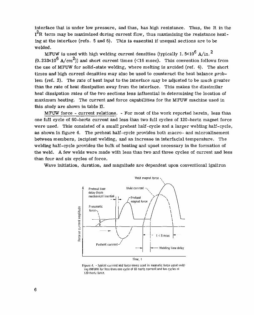
MFUW force - current relations. - For most of the work reported herein, less than one full cycle of 60-hertz current and less than two full cycles of 120-hertz magnet force were used. This consisted of a small preheat half-cycle and a larger welding half-cycle, as shown in figure 4. The preheat half-cycle provides both macro- and microalinement between members, incipient welding, and an increase in interfacial temperature. The welding half-cycle provides the bulk of heating and upset necessary in the formation of the weld. A few welds were made with less than two and three cycles of current and less than four and six cycles of force.
Wave initiation, duration, and magnitude are dependent upon conventional ignitron
' Preheat time delay (from
._ c m E c
5
Weld magnet force 7,
Weld c u r r e n t -,
Time, t
Figure 4. - Typical current and force waves used in magnetic force upset weld- i n g (MFU\V) for less than one cycle of 60-hertz current and two cycles of 120-hertz force.
6

"heat" settings. In the case of the magnetic force wave, however, magnet gap may also be adjusted to vary the force magnitude at one ignitron setting. By adjusting the ig- nitron setting and magnet gap, then, the time relation between force initiation and cur- rent initiation may be varied while force magnitude is held relatively constant.
There is an inherent time delay of the force wave of about 0.5 millisecond, due to the mechanical inertia of the welding head (or movable platen). This is the time required to transmit the force from the magnet to the workpieces. Thus, there will actually be a slight force delay when the force and current ignitron settings are the same.
decreased (e. g. , 50 percent to 40 percent "heat" setting) while keeping the current setting constant. A constant force magnitude is retained by decreasing the magnet gap, which effectively increases peak force back to the original value. This is necessary since a decrease in ignitron setting also decreases peak force.
To delay the force wave even more behind the current wave, the ignitron setting is
Peak welding current was measured with a Duffers' Current Analyzer. Wave-shapes of primary and secondary current, magnetic force, and primary and secondary voltage were recorded on an ultraviolet light sensitive recording instrument (Visicorder).
Weld Evaluation
Tensile tests. - The welded T-joints were sectioned in various ways to provide several types of tensile and metallographic specimens. Three types of tensile speci- mens were used. The sheet-type specimen (termed "small tensile specimen"), shown in figure 5(a), was machined from the sheet and planes parallel to the sheet surfaces through the plate. A tab from the unaffected sheet material was welded onto the plate side of the small specimen to provide increased length for testing purposes. The gage section was 1/2 inch (12.7 mm) long with a 0.188-inch by 0.060-inch (4.77-mm by 1.53- mm) cross section. Tensile testing was done in air at room temperature with a strain rate of 0.1 inch per inch per minute. Only specimens of 17-7PH plate heat treated t o TH1100 were tested in this configuration.
The other two types of tensile specimens were designed to test the entire T-joint (termed '?full-size tensile specimens"). One had a stress concentration present at the sheet-plate interface under the weld fillet (fig. 5(b)). The other had the weld fillet hand- filed to remove the stress concentration (fig. 5(c)). Both types of specimens were tested with conventional serrated tensile grips and a threaded pull rod that fit in the tapped hole in the plates, as shown in figure 5(b). An accurate weld area could not be measured for the full-size tensile specimens. So the T-joints were compared by taking the failure loads, dividing by the sheet cross-sectional areas, and expressing the resultant sheet stresses at weld failure as percentages of the sheet ultimate tensile strength (UTS). It
7

Tensile testing direct ion
,-Full-size tensile I specimen
Electron beam weld (tab.
(a) Location of small tensile specimen and metallographic sections.
A Stress concentrat ion7 - . ~ .
t i on
(b) Ful l-size tensi le test ing with serrated (c) Full-size tensile specimen with gr ips and tapped hole. weld f i l let f i led to remove stress
concentration.
Figure 5. -Cocation and types of tensile and metallographic specimens machined from T-joint.
should be pointed out that the sheet UTS for the particular sheet material used in each T-joint was used to calculate this percentage (i. e. , Type 304, 17-7PH, and 17-7PH in the TH1100).
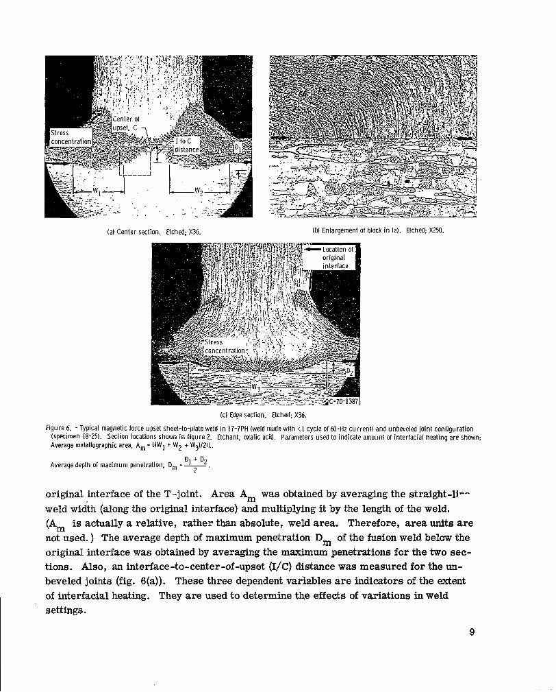
Metallographic evaluation. - Metallographic specimens were machined from some of the specimens at two sections transverse to the weld joint at the center and edge, as indicated by A and B in figure 5(a). They were mounted, polished, and etched with oxalic acid. An average metallographic area Am was measured for each specimen (see fig. 6). From many observations, the Am was found to approximate the fusion weld area on a plane through the original interface. The large arrows shown in figure 6 point to the
8
(a) Center section. Etched; X36. (b) Enlargement of block in (a). Etched; X250.
(c) Edge section, Etched; X%. Figure 6. - Typical magnetic force upset sheet-to-plate weld in 17-7PH (weld made with ~1 cycle of 6 0 - H ~ current) and unbeveled jo int conf igurat ion
(specimen 18-25). Section locations shown in f igure 2. Etchant, oxalic acid. Parameters used to indicate amount of interfacial heating are shewn: Average metallographic area, Am = ((w1 + W2 + W3)/211.
Average depth of maximum penetration, Dm = v2 2 .
original interface of the T-joint. Area A, was obtained by averaging the straight-1P- weld width (along the original interface) and multiplying it by the length of the weld. (A, is actually a relative, rather than absolute, weld area. Therefore, area units a r e not used. ) The average depth of maximum penetration Dm of the fusion weld below the original interface was obtained by averaging the maximum penetrations for the two sec- tions. Also, an interface-to-center-of-upset (I/C) distance was measured for the un- beveled joints (fig. S(a)). These three dependent variables are indicators of the extent of interfacial heating. They are used to determine the effects of variations in weld settings.
9

Welding parameters. - The decrease in length A L of the sheet was measured for each welded specimen and used as a measure of the upset. Essentially, all the upset takes place in the material sticking out of the tooling since it is heated and not fully con- strained.
Stickout S is measured from the last point of contact with the tooling to the end of the sheet, as shown in figure 2, for a 0.030-inch (0.76-mrn)/45' chamfer. However, in order to compare variations of this chamfer (fig. 2(c)), an "effective" stickout was used. For the 0.015-inch (0.38-mm)/45' chamfer,' 0.0078 inch (0.20 mm), or 1/128 inch, was added to the measured stickout. And for the 0.030-inch (0.76-mm) radiused tooling, 0.0039 inch (0.10 mm) was subtracted. These corrections follow from heat balance con- siderations.
Delay D is defined as the time delay of the initiation of the force wave after the beginning of the welding current wave. It was estimated from the Visicorder traces.
RESULTS AND DISCUSSION
Over 150 welds were made in this study to evaluate the effects of welding variables on joint properties. The best combinations of welding parameters found, based on tensile strengths and metallographic observations, are shown in table III. Only param- eters for short-time welds made with less than one cycle of 60-hertz current, and less than two cycles of 120-hertz magnet force are shown. Longer time welds were tried, but were judged t o be unsatisfactory.
Selected specimens were tensile tested and metallographically examined. The tensile test resu l t s a re shown in table IV for unbeveled joints and in table V for beveled joints. Variations in welding parameters are responsible for the scatter in the data shown.
Mechanical Properties
Unbeveled joints. - The tensile results are shown in table IV for unbeveled joints. The best weld settings of those used are shown in table III. For the 17-7PH/17-7PH (TH1100) joints tested full size (stress concentration present), the best weld strength obtained was 63 percent of the sheet UTS (i. e. , when the weld failed, the sheet was stressed to 63 percent UTS). Sheet stress has been used since the weld area could not be accurately measured. All the welds were irregularly shaped combinations of fusion and solid-state welds.
For the full-size specimens, the stress concentration present at the junction of the
10
sheet and plate under the weld fillet (see fig. 6) caused failure at low tensile strengths. Fracture, initiated at the stress concentration, easily propagated through the 17-7PH plate which has low ductility in the short transverse direction (see table I). Type 304 sheet has only about half the strength of 17-7PH sheet (in the THllOO condition). Although tensile data are not available for Type 304 plate in the short transverse direction, it is generally accepted that the Type 304 plate is both weaker and more ductile than 17-7PH plate in the short transverse direction. However, joints with Type 304 plates were as strong as those with 17-7PH plates (specimens C9-1 and 18-12, table IV). The reason for this is thought to be the higher ductility of Type 304 plate in the short transverse direction and the resistance to crack propagation from the stress concentration it offers. Further evidence of the beneficial effect of the Type 304 ductility is given by the 100 per- cent UTS values for the Type 304/Type 304 joints in table IV. When the stress concen- tration was removed by machining the small tensile specimen in 17-7PH/17-7PH joints, base metal strength was attained.
140 ksi (964 MN/m2) with yield strengths of 134 ksi (920 MN/m2) and 4 to 6 percent elongation were achieved (see specimens 18-21, 18-24, and 18-25 in table IV). These weld strengths are good when compared to the lower average plate strength of 144 ksi (990 MN/m2) shown in table I. Weld ductility is also higher than the plate average. The higher sheet strength of 17-7PH could not be attained, probably because weld strength was limited by the relatively weak plate.
For the small-size tensile specimens of 17-7PH, ultimate tensile strengths over
Beveled joints. - Tensile tests on full-size specimens produced from beveled joints indicated that removal of the stress concentration under the fillet resulted in higher joint strengths. For example, as high as 86 percent sheet UTS was reached for 17-7PH/ 17-7PH beveled joints tensile tested full size with the stress concentration removed (specimens J9-5 and J9-6 in table V). This is an increase of about 25 percentage points over beveled joints tested with the stress concentration present (specimens 59-3 and 59-4). Welding parameters used are shown in table III. By using the ductile Type 304 plate, slightly higher strength welds (88 percent sheet UTS) were obtained even with the stress concentration present (specimens J9-7 and J9-8). Again, the advantage of the more ductile Type 304 plate is seen. Lf the stress concentration is not removed, the beveled 17-7PH/17-7PH joints are no stronger than the unbeveled joints, as can be seen by comparing table IV (specimens C9-1 and C9-3) and table V (specimens 59-3 and J9-4).
Tests on the small tensile specimens indicated ultimate tensile strengths as high as 160 ksi (1100 MN/m2) with yield strengths over 143 ksi (985 MN/m2) were achieved with the beveled 17-7PH/17-7PH joints (table V). However, actual weld strengths were higher than this in some cases since failure occurred in the plate. The relatively poor plate properties then limit the theoretical joint strength (i. e. , the strength of the 17-7PH sheet).
11

Although high strengths were achieved with multiple-cycle beveled joints (table V(b)), they are not recommended. The marginal solid-state welds formed had poor resistance to crack propagation, as shown by the low strength of the full-size tensile specimens (table V(a)).
Metallography
Unbeveled joints. - The unbeveled sheet-to-plate T-joint consisted of both solid-state and fusion welds (principally grain boundary melting) for the settings shown in table ITI. Transverse metallographic sections from the center and edge of a 17-7PH joint are shown in figure 6. The large arrows indicate the location of the original interface. As can be seen in the center section (figs. 6(a) and (b)), fusion welding occurred at the outside and incipient solid-state welding in the center. In the edge section (fig. 6(c)), only fusion welding occurred.
The fillets formed at the base of the sheet section (fig. 6) are the result of the chamfer in the electrode tooling. However, notice that the sheet and plate are not com- pletely welded under the fillets and stress concentrations are present. Hot sheet ma- terial at the outside has come into contact with the cold plate surface, and the resultant stress concentration is s imi la r to a "cold shut" sometimes found in castings and forgings.
In both sections shown in figure 6, locaiized heating has occurred just above the fillet, actually at the last point of contact between the sheet and tooling, before upset. The reason for this is that most of the current enters the sheet from the tooling at this point. Hardly any current enters the 17-7PH sheet along the rest of its length because of its high resistance as compared to the copper tooling.
The reason for the "dumbbell-shaped'' appearance of heated material in the center section (fig. 6(a)) is the occurrence of the "skin effect. " This effect is normally asso- ciated with higher frequency current as commonly used in induction heating. However, the occurrence of this effect at 60 hertz has been described (ref. 7). The rapid rise of current I with respect to time t (dI/dt) used in this program also favors the skin effect. Briefly, the skin effect is the tendency for current passing through a conductor to con- centrate in a tubular element near the surface. The current density is then highest just below the surface and decreases towards the center of the conductor. The higher cur- rent density results in melting near the outside surface. The lower density results in various degrees of solid-state welding at the center (fig. 6(b)). The skin effect is not normally seen in conventional resistance welding because multiple cycles of current are used. In this study, welds made with three cycles of current did not have the skin effect.
The shape of the heated material in the weld joint is shown schematically by the three sections in figure 7. The section drawings have been constructed from many actual
12

TSolid-state weld
Fusion weld 7 ', \ r Incipient solid-state weld
Section A-A: view of plane through or ig inal interface.
,-Original interface 7 Section B-B: Just inside sheet Section C-C: Middle of sheet specimen surface (heated specimen thickness. material crosshatched).
Figure 7. -Various sections through unbeveled welded joint showing geometry of healed material.
metallographic sections, and the reasons for their shapes will be discussed in the next section.
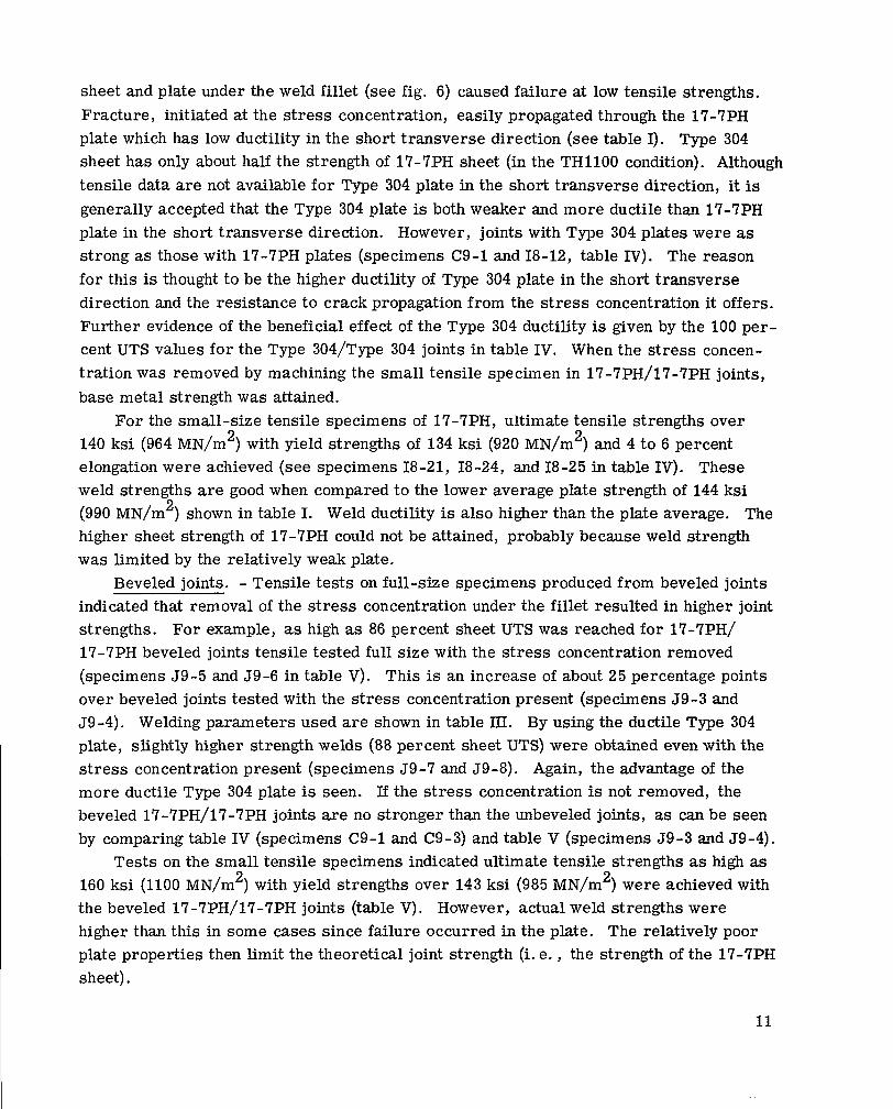
Beveled joints. - With the proper weld settings (table III), a fusion weld was ob- tained for the entire sheet width in the beveled joint. The skin effect was avoided since the bevel constricted the current. This caused a high current density across the initial contact thickness. However, i f the initial contact thickness was too large, the skin effect still occurred. Typical transverse center and edge sections with fusion welding are shown in figure 8. Figure 8(b) shows the typical grain boundary melting that occurred. The weld is similar for both sections, but the penetration is greater at the edge. (Large arrows in fig. 8 indicate original interface location. ) The reason for this is the "edge effect" as described in the appendix.
Very little welding is present under the fillets in either section shown in figure 8 .
This situation can be improved by decreasing the bevel angle, which increases the weld
13
(al Center section Etched; X36. (bl Enlargement of block in (a). Etched; X250.
(cl Edge section. Etcned; X%.
Figure 8. - Typical magnetic force upset sheet-to-plate weld in 17-7PH (made w i th less than 1 cycle of @-Hz current) and beveled (0.020 in. (0.51 mml 145") joint configuration (specimen H8-121. Etchant, oxalic acid.
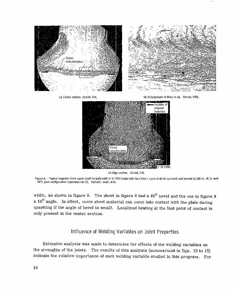
width, as shown in figure 9. The sheet in figure 8 had a 45' bevel and the one in figure 9 a 15' angle. In effect, more sheet material can come into contact with the plate during upsetting if the angle of bevel is small. Localized heating at the last point of contact is only present in the center section.
Influence of Welding Variables on Joint Properties
Extensive analysis was made to determine the effects of the welding variables on the strengths of the joints. The results of this analysis (summarized in figs. 10 to 15) indicate the relative importance of each welding variable studied in this program. For
14
(a) Center section. Etched; X36.
(b) Edge section. Etched; X36.
Figure 9. - Typical magnetic force upset sheet-to-plate weld (made wi th less t han 1 cycle of 60-Hz current ) and beveled (0.015 in. (0.38 mm)/15"l joint configuration (specimen C9-17). Etchant, oxalic acid.
unbeveled joints stickout S, decrease in sheet length AL, the ratio AL/S, and delay D were all important in obtaining highest strengths. For beveled joints, only AL and D were important.
Slight variations occur in the weld parameters (of the type shown in table ?X) that are considered constant for each point plotted in figures 10 to 15. But, from observation of many specimens, it is felt that these variations do not significantly influence the relation between the parameters shown in each figure.
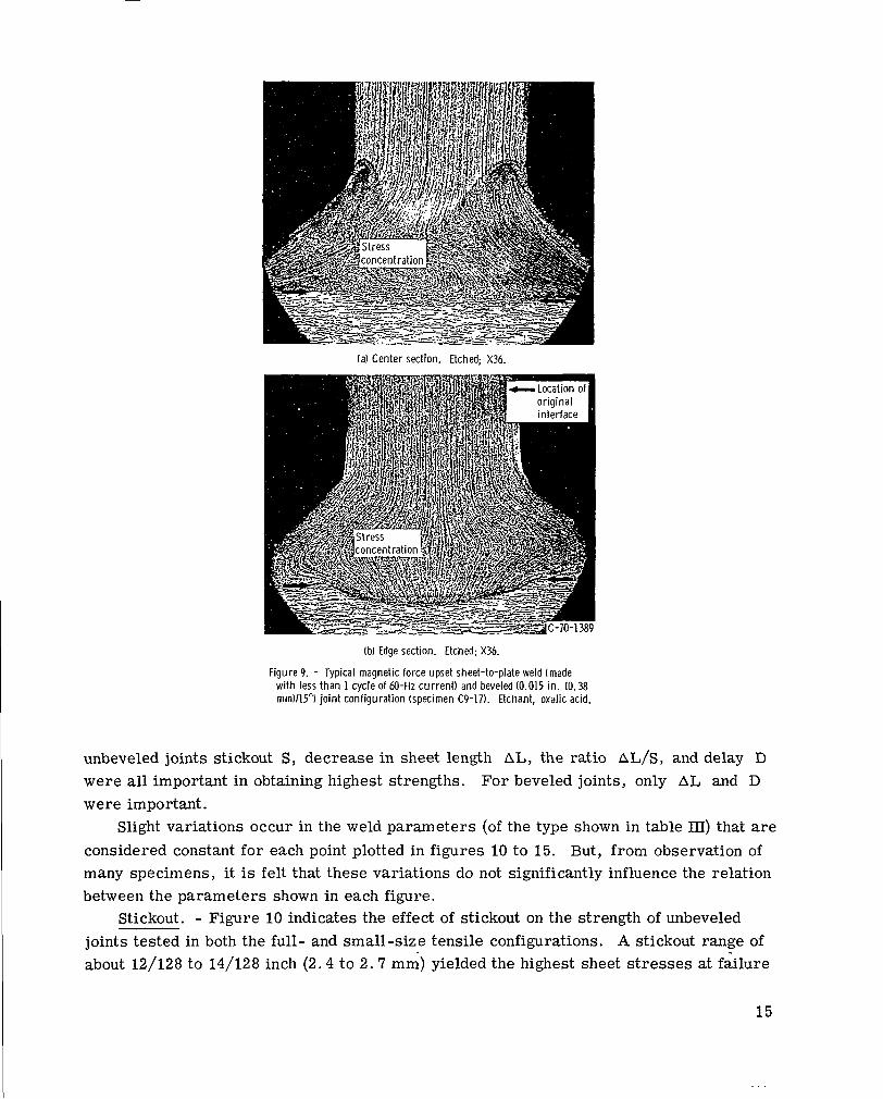
Stickout. - Figure 10 indicates the effect of stickout on the strength of unbeveled joints tested in both the full- and small-size tensile configurations. A stickout range of about 12/128 to 14/128 inch (2.4 to 2.7 mm) yielded the highest sheet stresses at failure
I 15
0 Sheet stress at weld failure (full-size tensiles) A Weld stress (small tensiles) f Fai lure away from weld and weld-heat-affected zone .-
Y 160 r VI
I / VI VI
2 c VI
L 0
5 c w m
c L VI
I I 8 10 12 14 16 18
Stickout, S, 11128 in.
0
1.8 2.2 2.6 3.0 3.4 Stickout, S, m m
Figure 10. - Effect of stickout on jo int strength of unbeveled 17-7 PHlType 304 and 17-7 PHl17-7 PH T-joints.
for unbeveled joints. This range provided the best heat balance at the sheet-plate inter- face. Larger stickouts resulted in (1) too much sheet heating away from the interface and (2) the center of upset moving well away from the interface (see fig. 6(a)). Small stickouts did not allow sufficient heat t o be developed at the interface because the close- ness of the copper tooling dissipated the heat too rapidly. In either case, little fusion welding and a weak incipient solid-state weld resulted. Removal of the stress concen- tration, by machining the small tensile specimen, resulted in about a 35-ksi (241-MN/m ) strength increase (compare the two curves in fig. 10).
2
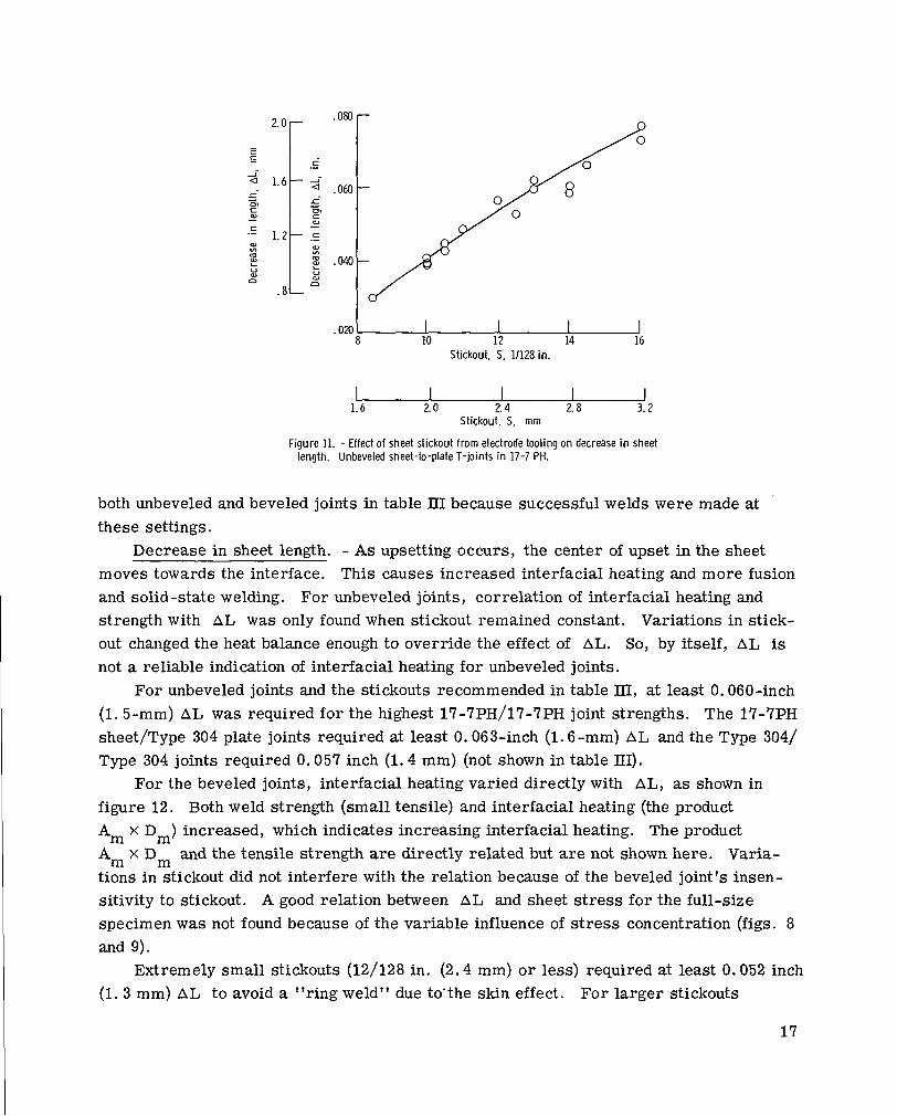
For the unbeveled joints, decreases in sheet length AL vary directly with stickout, as shown in figure 11, if welding current, force, and delay are held constant. Since more sheet sticks out from the tooling, a greater material volume is heated, softened, and upset. This follows since the bulk of the sheet sticking out as well as the portion near the interface, is resistance heated.
Beveled joint strength was not as dependent upon stickout as that of unbeveled joints. The reason is that heating is concentrated at the interface by the sheet bevel. The bevel constricts the current, causing a high density, and the interface is locally heated.
The 13/128- to 14/128-inch (2.6- to 2.7-mm) stickout range is recommended for
16
020 I I I I 8 10 12 14 16
Stickout, S, 11128 in.
1.6 2.0 2.4 2. 8 3.2 Stickout. S, m m
Figure 11. - Effect o f sheet stickout from electrode tooling o n decrease in sheet length. Unbeveled sheet-to-plate T-joints in 17-7 PH.
both unbeveled and beveled joints in table III because successful welds were made at these settings.
Decrease in sheet length. - As upsetting occurs, the center of upset in the sheet moves towards the interface. This causes increased interfacial heating and more fusion and solid-state welding. For unbeveled joints, correlation of interfacial heating and strength with AL was only found when stickout remained constant. Variations in stick- out changed the heat balance enough to override the effect of AL. So, by itself, AL is not a reliable indication of interfacial heating for unbeveled joints.
For unbeveled joints and the stickouts recommended in table lTI, at least 0.060-inch (1.5-mm) AL was required for the highest 17-7PH/17-7PH joint strengths. The 17-7PH sheet/Type 304 plate joints required at least 0.063-inch (1.6-mm) AL and the Type 304/ Type 304 joints required 0.057 inch (1.4 mm) (not shown in table III).
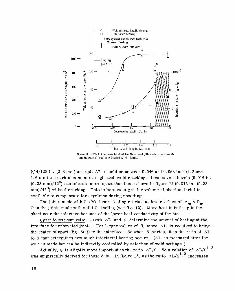
For the beveled joints, interfacial heating varied directly with AL, as shown in figure 12. Both weld strength (small tensile) and interfacial heating (the product Am x Dm) increased, which indicates increasing interfacial heating. The product Am x Dm and the tensile strength are directly related but are not shown here. Varia- tions in stickout did not interfere with the relation because of the beveled joint's insen- sitivity to stickout. A good relation between AL and sheet stress for the full-size specimen was not found because of the variable influence of stress concentration (figs. 8 and 9).
Extremely small stickouts (12/128 in. (2.4 mm) or less) required at least 0.052 inch (1. 3 mm) AL to avoid a "ring weld" due to'the skin effect. For larger stickouts
17
lm0r
n Weld ultimate tensile strength 0 Interfacial heating
Solid symbls denote weld made with
Failure away from joint
Mo insert tooling
I
160 t / = . !
- "t 0
Decrease in length, AL, in.
. 8 1.0 1.2 1.4 1.6 1.8 Decrease in length, AL, mm
Figure 12. - Effect of decrease in sheet length on weld ultimate tensile strength and interfacial heating in beveled 17-7PH joints.
((14/128 in. (2.8 mm) and up), AL should be between 0.046 and U. 063 inch (1.2 and 1.6 mm) to reach maximum strength and avoid cracking. Less severe bevels (0.015 in. (0.38 mm)/l5') can tolerate more upset than those shown in figure 12 (0.015 in. (0.38 mm)/45') without cracking. This is because a greater volume of sheet material is available to compensate for expulsion during upsetting.
The joints made with the Mo insert tooling cracked at lower values of Am X Dm than the joints made with solid Cu tooling (see fig. 12). More heat is built up in the sheet near the interface because of the lower heat conductivity of the Mo.
Upset to stickout ratio. - Both AL and S determine the amount of heating at the interface for unbeveled joints. For larger values of S, more AL is required to bring the center of upset (fig. 6(a)) to the interface. So when S varies, it is the ratio of AL to S that determines how much interfacial heating occurs. (AL is measured after the weld is made but can be indirectly controlled by selection of weld settings. )
Actually, S is slightly more important in the ratio AL/S. So a relation of AL/S1' was empirically derived for these data. In figure 13, as the ratio AL/S1. increases,
18

D Weld ult imate tensile strength 0 Interfacial heating
So l i d symb l denotes weld made w i th Mo insert tool ing
t Failure away f rom jo in t 160
.7 .8 . 9 1.0 1. 1 Ratio of decrease in sheet length to stickout, ALlS1.2
Figure 13. - Effect of rat io of decrease in sheet length to stickout on weld uI- timate tensile strength and interfacial heating. Specimens machined from unbeveled sheet-to-plate T-joints of 17-7 PHlType 304 and 17-7 PH117-7 PH.
tensile strength and the product Am X Dm also increase. These dependent variables a r e both indications of interfacial heating. And too much heating (AL/S1' 2 0.975) results in cracking. Too little heating (AL/S1* < O . 9) results in a weak weld.
The interface-to-center-of-upset (I/C) distance (fig. S(a)) is an indication of the amount of interfacial heating. As the center of upset moves closer to the interface, more heating and welding occur. For small values of I/C, high weld strengths resulted The empirical ratio AL/S1* determines the location of the center of upset. As pre- viously described, when this ratio increased, so did the interfacial heating. Thus, the center of upset moved closer to the interface, as shown in figure 14. Again, too much heating resulted in cracking.
Since the sheet bevel overrides (within reasonable limits) the influence of S, the ratio AL/S does not correlate with interfacial heating for beveled joints.
Delay. - Interfacial heating increases as the delay of the force half-wave behind the current half-wave increases (see fig. 4). This effect is shown in figure 15 in terms of fusion-weld fracture area and sheet stress at failure for various unbeveled joints. The fracture area is the approximate area of melted material pulled out of the plate in full- size specimen fracture (see fig. ?). For example, increased delay shifted the fracture from the plate to the sheet in a series of Type 304/Type 304 joints as the fusion-weld
19

Figure 14. - Effect of ratio of decrease in sheet length to stickout o n distance from weld inter- face to center of sheet upset. Unbeveled sheet-to-plate T-joints in 17-7 PHIType 304 and 17-7 PH117-7 PH.
68
48
0 Sheet stress, 17-7PHIType 304 0 Fusion-weld fracture area, Type 304IType 304 0 Fusion-weld fracture area, 17-7PH117-7PH
- P -I 070
I
060 Ne
E
.- m
m W L
3
O H 1 g
?
0402
c
- 9
c 0 m .-
; 030 2. Figure 15. - Effect of delay of magnet force init iation (relative to weld current1 on sheet stress at weld failure
and fusion-weld f racture area. Unbeveled sheet-to-plate full-size T-joints.
20

area increased. Relative strengths for these joints are shown in table IV (J9-9 to J9-15). Percent sheet UTS at weld failure for 17-'IPH/Type 304 joints increased from 38 to 50 percent for a"de1ay increase of 1 .0 to 1 .5 mil l isecond. These s t rengths are low be- cause a low preheat current half-cycle was used and the weld interface was not ade- quately heated.
When the force half-wave preceded the current half-wave (negative delay), little interfacial heating occurred. For example, one weld with a negative delay of 1 . 0 milli- second had an exceptionally low Am x Dm for its AL/& ratio.
Only 1.0-millisecond delay was used to obtain a full-section fusion weld for the beveled joints. This was due to the current and force concentrating effect of the bevel.
CONCLUDING REMARKS
This program was limited in scope since many of the possible variables were held constant so that the few described could be studied. I believe that some of the other variables should also be studied. Among these, the effect of smoother and rougher faying surface finishes on joint properties should be determined.
The value of using a weld current reading as an indication of weld quality should be examined. It is my opinion that weld current readings have been overemphasized in resistance welding technology and can be very misleading. In this study, for example, it was possible to have relatively high weld current readings and no interfacial heating o r welding. Weld voltage and resistance readings are much more valuable.
Because of the highly localized heating capability offered by MFUW, the process may be applicable to materials considered unweldable. Materials with low ductility and those adversely affected by heating from conventional welding processes may now be more weldable. Among these may be cast superalloys and fiber-reinforced composites.
SUMMARY OF RESULTS
Sheet-to-plate T-joints in AIS1 Type 304 and 17-7PH stainless steels were resistance welded by using the magnetic force upset welding (MFUW) process. The results are summarized as follows:
1. Full-strength welds were achieved in dissimilar thickness T-joints with both Type 304 and 17-7PH sheet and plate.
2 . A stress concentration existed at the sheet-plate interface under the weld fillet due to the presence of an unwelded area. Removal of the weld fillet (and elimination of the stress concentration) resulted in about a 40 percent strength increase in full-size
21

17-7PH/17-7PH T-joints. Almost all failures in these T-joints occurred through the weld heat-affected zone on the plate side of the weldment. The greater ductility of the Type 304 plate compared to that of the 17-7PH plate lessened the effect of the stress con- centration under the fillet.
3. Because of the possible existence of a s t r e s s concentration in this type of T-joint, ductility is a more important criterion than strength in selecting the plate material. Type 304 is preferred over 17-7PH as the plate material because of the low ductility of 17-7PH plate in the short transverse direction.
4. From metallurgical observations, the best welds were achieved with beveled joint configurations. A small sheet bevel angle and initial contact thickness (0.015 in. (0. 38 mm)/l5') are preferred. Beveled joints were principally fusion welded; whereas, unbeveled joints were a combination of fusion and solid-state welding.
5. For unbeveled joints, stickout S, decrease in sheet length AL, the ratio AL/S, and delay of force relative to current D were all important in obtaining highest strengths. For beveled joints only A L and D were important.
6. MFUW was a successful welding process in this study because heating was con- centrated at the interface between the two dissimilar section thicknesses. This was accomplished by delaying the initiation of the magnetic force wave and by using short weld-current times set by unique MFUW controls.
Lewis Research Center, National Aeronautics and Space Administration,
Cleveland, Ohio, May 5, 1970, 129-03.
22
APPENDIX - EDGE EFFECT
Figures 6 and 7 show that there is more fusion welding in the edge section than at the center. This is termed the "edge effect. ' I As resistance heating occurs at the sheet-plate interface, the "fusion-weld front" moves toward the center principally from the short edges, as shown by the arrows in figure 7. Increases in delay (force relative to current) increase the amount of fusion-weld-front movement. There are three inter- related reasons for the edge effect.
The f irst factor is mechanical. Pressure is not distributed uniformly across the sheet thickness or width at the original interface (ref. 8). Rather, it is highest at all four edges of the cold interface and decreases parabolically as the center is approached. T h i s causes contact resistance near the edges to be lower. And this favors more current flow and a higher current density near the edges.
Secondly, heating occurs in the form of a thin outer ring at the sheet-plate interface because of the skin effect. However, as the mater ia l temperature r ises , so does its electrical resistance. Current is forced inward, from both long and short edges, toward the cooler, lower-resistance material. Portions of the interface near the short edges receive increased current from both long and short edges. The current density is nec- essarily higher near the short edges. This causes the fusion-weld front to move inward faster from the short edges.
Thirdly, as the material near the edges is softened by resistance heating, it no longer is able to support the load. The pressure on the remaining material increases with a corresponding drop in contact resistance. This allows more current through the remaining center portion of the interface. Thus, resistance heating increases, and the fusion-weld front moves inward.
Thus, increased current density and more heating occur near the edges, just ahead of the moving fusion-weld front. So, all three of the factors described, together, cause the inward movement of fusion welding shown in figure 7.
Delay of the magnetic force initiation allows more inward movement of the fusion- weld front. In fact, too much delay results in excessive heating, expulsion and cracking. Too little delay does not allow enough heat to be developed, resulting in very little fusion and only a marginal solid-state weld. For the unbeveled joints, a delay of 1. 5 milli- seconds provided optimum amounts of fusion and solid-state welding. Complete fusion welding in unbeveled joints was accompanied by shrinkage cracking.
As magnetic force is applied, pressure increases sharply on the non-fusion-welded area of the interface. Contact resistance drops; and even though high current is avail- able, little resistance heating takes place because of the low contact resistance. Solid- state welding occurs because upsetting brings hot sheet material into close contact with the plate along the interface.
23

Less delay (1.0 msec) was used with the molybdenum-insert tooling when the un- beveled sheet was welded. The purpose of the molybdenum was to counteract the edge effect and force more current into the center of the joint. The molybdenum inser ts were shaped to form a more resistive path along the edge than the center. More heating took place toward the center, and less delay was required. However, there was a tendency to overheat the sheet at the last point of contact with the molybdenum because of i t s low heat conductivity.
24
REFERENCES
1. Del Vicchio, .E. J. , ed. : Resistance Welding Manual. Vol. 1. Third ed. , Resistance Welder Manufacturers' Assoc., 1956, Chs. 1 and 5.
2. Phillips, Arthur L. , ed. : Welding Handbook. Sect. 2. Fifth ed. , American Welding SOC., 1963, ch. 30.
3. Park, F. R. : Magnetic Force Welding. Product Eng. , vol. 29, no. 39, Sept. 15, 1958, p. 4.
4. Boolen, R. F. : Magnetic Force Welding Applications at Battelle Northwest. Rep. BNWL-422. Battelle-Northwest, May 1967.
5. Schueler, Arthur W. : Magnetic Force Butt Welding for Nuclear Cladding. Welding J. , vol. 47, no. 8 , Aug. 1968, pp. 638-643.
6. Funk, E. J. : Recent Developments in Magnetic-Force Welding. Welding J. , vol. 36, no. 6, June 1957, pp. 576-582.
7. Stevenson, William D. , Jr. : Elements of Power System Analysis. McGraw-Hill Book Co. , Inc., 1962.
8. Timoshenko, Stephen P. ; and Goodier, J. N. : Theory of Elasticity. Second ed. , McGraw-Hill Book Co. , Inc. , 1951.
9. Anon. : Properties of Some Metals and Alloys. The International Nickel Co. , Inc.
25

TABLE I. - ROOM-TEMPERATURE BASE METAL TENSILE PROPERTIES" OF
17-7PH AND AIS1 TYPE 304 STAINLESS STEELS
17-7PH Plate (tested in short transverse to rolling direction)
17-7PH Sheet (tested parallel to rolling direction)
17-7PH Sheet (ref. 9)b Type 304 sheet ( tested parallel
to rolling direction)
THl lOO (precipita- tion hardened)
TH1100
Solution annealed Mill annealed I
"Averaged values of th ree o r more t es t s . "Data is for a 2-in. (5.1-cm) gage length.
Ultimate tensi le
s t rength
645
yield 1/2 in.
- S
ks i
149
40 -"
(1.27 cm), percent
"" 2
1025 17
275 30 _"_ "
TABLE 11. - MAGNETIC FORCE UPSET WELDING
MACHINE CAPABILITIES
[Current and force waves independently controlled by phase shift heat controls. ]
Welding current:
200 kA at short c i rcui t Single-phase, 60 Hz, 440-V, 400-kVA transfornler
Force:
Magnet force, 6. 5 kips (27.9 N) peak Pneumatic force, 3.7 kips (16. 5 N) maximum Single-phase, ~O-HZ, 440- V, 100-kVA transformer
producing 120-Hz force wave
Brittle
Euctile
Ductile Ihc t i le
26

TABLE 111. - OPTIMUM WELD PARAMETERS FOR SHEET-TO-PLATE T-JOINTS TN
17-7PH AND AIS1 TYPE 304 STAINLESS STEELS
[Less than one cycle of 60-Hz current . ]
Paramete r
Material (sheet/plate)
Bevel, in. (mm)/deg Tooling chamfer,
in. (mm) /deg Stickout, S, in. (mm)
Current (peak),a kA Magnetic force (peak),a kips (kN)
Delay,a D, msec
Current duration, msec Force duration,a msec
Decrease in length, AL, in. (mm)
a
Ratio of dec rease in length to stickout, AL/S1.
aPreheat/weld, see fig. 4.
Unbeveled
1?"7PH/17"7PH
"""""""""""""
0.015 (0.38)/45 or 0.030 (0.76)/45 13/128 to 14/128 (2.6 to 2. 8)
45.5/60 3.45/3.7 (15. 3/16.4)
0 .5/1.5
4.7/6.0 5.7/5.9
0.060 to 0.067 (1.5 to 1.7)
0.92 to 0.96
17-7PH/17-7PH 17-7PH/Type 304
0.015 (0. 38)/15 0.030 (0.76)/45
13/128 to 14/128 (2. 6 to 2.8)
34/50 35/51 1. 5/4.0 (6.65/17. 8) 1. 5/3.8 (6.65/16.9:
1.5/1.0
4.6/5.7 4.6/5.9 4.9/6.2 4.9/6. 1
3.062 to 0.063 (1.57 to 1. 6)
27
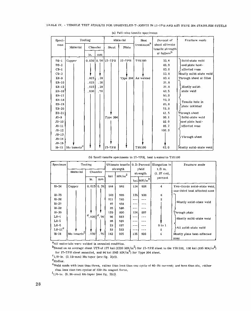
TABLE IV. - TENSILE TEST RESULTS FOR UNBEVELED T-JOINTS IN 17-7PH AND AIS1 TYPE 304 STAINLESS STEELS
(a) Full-size tensile specimens
Speci- men
Tooling rvaterial Heat treatmenta
Percent of sheet ultimate ensile strengtt
at failureb
Material I Chamfer Sheet Plate
-F in.
lopper 0.03(
- mm
). 76 -
! .38 .38 .38 .76
1 -
33. 6 46.0 63.0 53. 8 83. 4 37. 8 37. 8 40.5 50.0 73. 3 83.8 75.0 41. 5 90. 1 92.0 85.7
100.0
1 63.0
17-7PH
1 rype 304
1
Solidstate weld and plate heat- affected zone
Mostly solid-state weld
B9- 1 B9-2 c9-1 c 9 - 3 E8-9 E8-10 E8- 12 E8-16 E8-17 E8- 18 E8-19 E8-20 E8-21 J9-9 J9-10 J9- 11 59-12 59-13 59-14 J9- 15 18-12
THllOO
1 A s welded
! TH1100
1 .01! .01: .01! .03(
i lo inserts'
(b) Small tensile specimens in 17-7PH, heat treated to THllOO
1.2-Percent yield
Elongation ir 1/2 in.
(1. 27 cm), percent
Fracture mode Specimen Tooling Jltimate tensile strength r Material Chamfer strength
ININ/m2 - k s i
134 -
135 "_ "_ " _ 124 "- "_ "_ "- 135
-
in.
926
930
4
6
Two-thirds Solid-state weld, one-third heat affected zone
18-24 )er 0.01:
11
'. 03C
1 .030
18-25 18-26 18-21 18-28 18-30 L8-4 L8-5 L8-6 L 8 - l l e
7 143 111
67 85
129 96 86 23 83
142
985 765 4 64 586 890 663 595 157 572 975
Mostly solid-state weld
Through plate
J Mostly solid-state weld
All solid-state weld
Mostly plate heat-affected zone
aAll materials were welded in annealed condition. bBased on an average sheet UTS of 177 ksi (1220 MN/m2) for 17-7PH sheet in the TH1100, 130 ksi (895 MN/m2)
'1/8-in. (3.18-mm) MO taper (see fig. 2(c)). dRadius. eWeld made with less than three, rather than less than one cycle of 60-Hz current; and less than six, rather
'1/4-in. (6. 36-mn1) Ma taper (see fig. 2(c)).
for 17-7PH sheet annealed, and 94 ksi (645 MN/m2) for Type 304 sheet.
than less than two cycles of 120-Hz magnet force.
28

~~
TABLE V. - TENSILE TEST RESULTS FOR BEVELED T-JOINTS IN 17-7PH AND AIS1 TYPE 304 STAINLESS STEELS
(a) Full-size tensile specimens; tooling material, copper; chamfer, 0.030 in. (0.76 mm)
T T 1 Fracture mode Material I Sheet bevel ~ ~~
Heat :reatmenta
Percent of sheet ultimate ensile strengtl
at failureb
jpecimel
59-3 59-4 59-5 J9-6 59-7 J9-8 C9-6d C9-Id c9-10 c9-11 C9-12 C9-14 D9- 1
D9-2e
J9-1
59-2
- ingle,
deg
- 15
1 I
45
30 30 15 45 45
45
15
15
Plate
thickness contact Initial
in. mm
17-7PH
1 : Type ' 304 Type 304
0.38 0.015
17-7PH . 5 1 .020 .020
.25 .010
.51 .020
.51 .020
.76 .030
.64 .025
.51
Knife edge f
Type 304 0.38 0.015
Type 304 .38 .015
Sheet
' H 57.6 63.9
'85.6 534.2
88.4 87.0 21.2 19.0 51.7 44.6 43. 3 62.2 42. 1
24.6
58.0
99.4
7 7 -I ? P TH1100
1 As welded
As welded
Mostly plate heat- affected zone
1 All solid-state weld
i t Half solid-state weld,
half heat-affected zone
J
Through cracked fusion weld
Solid-state and plate heat- affected zone
Mostly plate heat-affected
f rype 304
rype 304
(b) Small tensile specimens in I I - IPH, heat treated to THIO0
T; ~~
Specimen Sheet bevel intimate tensilt strength
? Fracture mode Elongation in 0 .2-Perceni
yield 1/2 in. - (1.27 cm), strength -
MN/m2 percent
-
Tooling
Material Chamfer 1 -
ingle deg
- 45 45 30 30 15 45
1
Initial contact
thickness 4N/m2
855 840 383 517
1069 421
1105 1052 1048 940
ks i
- 124 122 56 75
155 61
161 153 152 137
- ks i
- "_ "_ "_ "_ 145 "_
143 146 118 126
-
in. mm -
in.
0.015 .015 .015 ,025 .015 .015
-
,020 .020 .032 .023
_.
mm - 0.38
.38
.3a
.64
.38
.38
.51
.51
.81
.58
L8- 1 L8-2 c9-8 c9-9 c9-17 c 9 - 5
Copper "" 1
0 2 1 0 0
0 2 6 4
Through plate
Mostly solid- s ta te weld
""
""
995 ""
985 1006 812 870
-
I - Through plate Mostly solid-
I s ta te weld C9-15d C9-16d 18-22 18-23
I } Through plate Mo insert Mo insert I Half plate heat-
affected zone,
I aAll mater ia ls welded in annealed condition. bSee footnote (b), table IV. 'Stress concentration removed, see fig. 5(c). dSee footnote (e), table 1V. eWeld made with less than two cycles of current and four cycles of magnet force. [1/4-in. (6. 36-mm) Mo taper (see fig. 2(c)). gRadius.
N A S A - L ~ I I ~ I C Y , 1970 - 15 E-5624 29