maglev - ucf department of · pdf filemaglev technology improve mass transit, but other...
TRANSCRIPT

i
MagLev
Group 2
8/1/2013
Julio Arias Sean Mawn
William Schiller Leo Sell

2
Table of Contents 1.0 Executive Summary 1 2.0 Project Description 2 2.1 Project Motivation and Goals 4 2.2 Objectives 6 2.3 Project Requirements and Specifications 6 2.3.1 Levitation 7 2.3.1.1 Vehicle 8 2.3.1.2 Track 8 2.3.2 Remote Control 9 2.3.3 Android Application Interface 10 3.0 Research Related to Project Definition 14
3.1 Bibliography of Related Work 14 3.1.1 Linear Motor for Maglev Train 1997 W. Beaty 14
3.1.2 Antipodes Magnetic Levitation Vehicle 14 3.1.3 Small Scale Magnetic Levitation Train 15 3.2 Relevant Technologies 16 3.2.1 Microcontrollers 16 3.2.1.1 Atmega328P 19 3.2.1.2 RN-42 21 3.2.1.3 RN-52 23 3.2.2 Application Development 26 3.2.2.1 iPhone Development 27 3.2.2.2 Android Development 28 3.2.2.3 Android Smartphones 30 3.2.3 Wireless Communication 32 3.2.3.1 Wi-Fi Communication 32 3.2.3.2 Bluetooth Communication 32
3.2.4 Electromagnets 35 3.2.5 Solenoid 36 3.2.6 H-Bridge Circuit 37 3.2.7 H-Bridge ICs 38 3.2.7.1 TI SN754410 39 3.2.7.1.1 SN754410 Truth Table 40 3.2.8 Hall Effect Sensors 41 3.2.8.1 Allegro A1301 Hall-effect sensor IC 42 3.2.8.2 Optek OH090U 44 3.2.8.3 Melexis US1881 44 3.3 Levitation 45 3.3.1 Static Magnets vs. Electromagnets 45 3.3.2 Lifting Power calculations 47 3.4 Distance Tracking With Sensors 48 3.5 Three-Phase Drive System 50

3
3.5.1 Approaching N-Pole (-B) magnet 50 3.5.2 Perpendicular to N-Pole (-B) magnet 51 3.5.3 Leaving N-Pole (-B) magnet 51 3.5.4 Test Case scenarios for the Drive System 55 4.0 Project Architecture and Software Design Details 4.1 Initial Design Architecture 55 4.1.1 Track design 55 4.1.1.1 Track Design: Propulsion and Levitation 63 4.1.2 Solenoid Design 69 4.1.3 Car Design 70 4.1.3.1 Lego Design 70 4.1.3.2 Wood Design 70 4.1.4 Car Prototype Diagrams 71 4.1.4.1 First Car Prototype 71 4.1.4.2 Second Car Prototype 72 4.1.5 Car Materials 72 4.1.6 Building Plan for First Prototype 73 4.2 Microcontroller functions 75 4.2.1 Programming functions 75 4.2.1.1 Receiving order from Bluetooth 75 4.2.1.2 Taking the Hall Effect input 76 4.2.1.3 Microcontroller conversion function 77 4.2.1.4 Sending the Signal to the TI SN754410. 79 4.2.1.5 Bidirectional vehicle 85 4.4 Android Application Development Architecture 86 4.4.1 Application Class Diagram 87 4.4.2 Application Programming Plan 88 4.5 Interfacing Microcontroller and Remote 93 4.5.1 General Communication through the System 94 4.5.2 Establishing a Connection 95 4.5.3 Client-Server 95 4.5.4 Commands Exchanged 97 5.0 PCB Circuit design 98 5.1 Arduino Interfacing 98 5.1.1 Interfacing A1301 with the Arduino Board 98 5.1.2 Interfacing SN754410 with the Arduino 99 5.1.3 Interfacing Bluetooth with the Arduino 101 5.2 Arduino ProtoShield PCB surface 103 6.0 Project Prototype Testing 104 6.1 Hardware Testing Environment 104 6.2 Testing the Hall-Effect Sensors 105 6.3 System Testing 106 6.3.1 Initial Testing of Android Application 107

4
6.3.2 Bluetooth communication to the Atmega328P 108 6.3.3 Testing Hall Effect Sensor to the Atmega328P 109 6.3.4 Testing Solenoid Polarity and H-Bridge Function 110 6.3.5 Testing Atmega328P Output to H-Bridge Circuit 111 6.3.6 Hall Effect Sensor through Solenoid function 112 6.3.7 Final Prototype Testing 113 6.4 Facilities and Equipment 113 6.5 Conclusion 115 7.0 Administrative Content 115 7.1 Milestone Discussion 115 7.2 Budget and Finance Discussion 116 7.2.1 Vehicle 116 7.2.2 Track 117 7.2.3 Other features 118 7.2.4 Financial Diagram 119 7.3 Bill of Materials 120
Figures
Figure 2.1 – EMS technology for the maglev rail. 3 Figure 2.2 – EDS technology for the maglev rail 3 Figure 2.3 – [1] Inductrack technology 4 Figure 2.4 – The JR-Maglev design 5 Figure 2.5 – Halbach array fundamentals 7 Figure 2.6 – An example of a Halbach array using magnetic rods 8 Figure 2.3.3.1 – Main Menu 11 Figure 2.3.3.2 – Controlling Interface 13 Figure 3.2.1.2a- RN-42 Block diagram 21 Figure 3.2.1.2b- Pin Diagram 22 Figure 3.2.1.3a- RN-52 Pin Diagram 24 Figure 3.2.4: Magnetic Field intensity 35 Figure 3.2.5: Tightly Spaced turns vs. loosely spaced turns of a solenoid 36 Figure 3.2.6.1: Scenario 1 1 – S1 high and S2 Low 37 Figure 3.2.6.2: Scenario 2 – S2 high and S1 Low 38 Figure 3.2.7: Pin layout for the TI SN754410 39 Figure 3.2.7.1.1 TI SN754410 diagram 41 Figure 3.2.8.1.1: The functional block diagram of an Allegro A1301 42 Figure 3.2.8.1.2: Graph of the Magnetic Sensitivity 43 Figure 3.2.8.3: Specifications of the three hall-effect sensors. 45 Figure 3.1 – Magnetic Force vs. Distance chart 46 Figure 3.2 – A simple electromagnet 46 Figure 3.3.2: Free Body Diagram for achieving levitation 47 Figure 3.3.2.1: Diagram displaying LSM propulsion 48 Figure 3.4: Interaction between sensors and track magnets 50 Figure 3.5: Three-Phase sinusoidal wave diagram 51

5
Figure 4.1 – Rough sketch of straight track 56 Figure 4.2 – Initial circular track design 57 Figure 4.3 – The rough sketch of the track 58 Figure 4.4 – The arc dimensions shown 59 Figure 4.5 – Straightaway dimensions shown 59 Figure 4.5.1 – Magnetic field of a rectangular magnet 63 Figure 4.6 – Magnetic calculator 64 Figure 4.7 – Rough sketch of the passive coils 65 Figure 4.8 – A halbach array using neodymium magnets 66 Figure 4.9 – The cutout view of a prototype track design 67 Figure 5.0 – The side-view cutout of the track 68 Figure 5.1 – A mock representation of the Team Antipodes 68 Figure 4.1.4.1: Top view of 1st car Prototype 71 Figure 4.1.4.2: Top view of 2nd car Prototype 72 Figure 4.2.1.1 - Bluetooth Block diagram 75 Figure 4.2.1.2 – Hall effect Block diagram 76 Figure 5.1.1.4.1 – Switch signal block diagram 79 Figure 5.1.1.4.2 – NS magnet block diagram 81 Figure 5.1.1.4.3 – SN magnet block diagram 82 Figure 5.1.1.4.4 – No magnet block diagram 83 Figure 5.1.1.4.5 – Aligned Magnet block diagram 84 Figure 5.1.1.4.6 – double sided diagram 85 Figure 4.4.1 Class Diagram – Maglev Controller 87 Figure 4.4.1.1 Class Diagram (continued) 92 Figure 4.5.1 Communication through System Model 94 Figure 4.5.3 Client-Server Model 96 Figure 5.1.1: Connections between the A1301 sensors and Arduino Board 99 Figure 5.1.2: Connections between the Arduino, H-Bridge drivers, and Solenoids 100 Figure 5.1.3: Connections between the Arduino and RN41 101 Figure 5.1.3.1: Total Eagle Schematic 102 Figure 5.2: ProtoShield Schematic 104 Figure 6.2: Circuit for testing the A1301UA sensors 106 Figure 7.2.4 – Financing 120

6
Tables
Table 3.2.1.2a- Configuration Values 21 Table 3.2.1.2b- Switch and Pin Setup 22 Table 3.2.1.3b - RN-52 Pin table 25 Table 3.2.2.2 Android vs iPhone Development Table 30 Table 3.2.3.2 Comparison chart – Bluetooth vs Wi-Fi 34
Table 3.2.7.1: Pin Numbers and Functions 40 Table 3.2.8.1.3: Pin connections of the Allegro A1301 43 Table 6.3.2 – Bluetooth Controller Communication Test Table 109 Table 6.3.3 – Hall effect reading Test Table 110 Table 6.3.4 – H-Bridge Control Test Table 111 Table 6.3.6 – System function Test Table 112 Table 6.3.7 – Prototype Test Table 113 Table 6.4 Software Summary 115 Table 7.2.4 – Financial Table 119

1
1.0 Executive Summary
Magnetic levitation or otherwise known as “maglev” technology is a system where propulsion is achieved through magnetic fields. This technology does not use any mechanical method of propulsion such as wheels, axles, et cetera. Our design proposal is that of a scaled-down version of the maglev train technology that is in its infancy today. This technology is in use overseas, albeit, most of the breakthroughs that are related to maglev are strictly experimental. Commercial maglev rails are few and far between as there are only 2 rails in existence today that transport people. Our maglev rail will feature a modified version of the Inductrack maglev design as well as Electromagnetic Suspension design ideas. The vehicle will feature a 3-phase linear motor mounted on the underside. The vehicle will also be equipped with permanent magnets that will react with the track to create levitation. For levitation, the track will be outfitted with two rows of permanent magnets, arranged in a Halbach array. This arrangement will direct the magnetic field towards the underside of the vehicle. The on-board permanent magnets will react with the track as stated above, and will result in levitation. This track will be a circular track to demonstrate the speed capabilities of maglev technology. While our vehicle will have the ability to go forward and backward, with a circular track, we can apply fully power to the vehicle to demonstrate an important feature of maglev technology: high speed. The vehicle will be controlled via a mobile device. The mobile device will interface with a Bluetooth module on the vehicle and will be able to be controlled wirelessly from the device. The cost of the project is estimated to be in the range of $600-$900 US dollars. In order for this project to be a success, the vehicle must demonstrate all capabilities of maglev technology which include:
Levitation achieved via magnetic fields
Propulsion achieved via magnetic fields
Controlled via mobile device
Adequately demonstrate the fundamental features of maglev technology: high speed, frictionless, and clean.
Maglev rail technology has virtually limitless potential. It can effectively change the entire infrastructure of mass land transit to something more efficient, and environmentally friendly. By moving towards maglev technology, our railways can improve upon transit time, maintenance costs, and emission output. Not only will maglev technology improve mass transit, but other transit systems such as military and freight have much to gain from maglev rail technology.

2
2.0 Project Description This project is an attempt to replicate the maglev transportation system that has been researched since the 1950’s with the advent of the first, working, full size linear induction motor developed by Dr. Eric Laithwaite. The idea of a transportation system relying solely on magnetic fields has been theorized since before the creation of the linear motor, however, only recently has the world seen actual maglev transportation systems for commercial use. The systems currently in use are located in Shanghai, China and Aishi, Japan. The system in use in Shanghai is the Transrapid system. The “Transrapid” is a German designed maglev system and the system in use in Aishi is the “Linimo”. While the Transrapid and Linimo systems are the only two commercial maglev systems, both South Korea and China have plans to construct native maglev systems which would bring the total to 4 operational, commercial maglev systems. There are currently 3 different types of maglev rail technology. These are Electromagnetic Suspension (EMS), Electrodynamic Suspension (EDS), and “Inductrack” (Permanent magnetic suspension). EMS uses electromagnets whose magnetic field is monitored and altered via a feedback loop. EDS uses on board superconducting magnets that are super cooled in tandem with magnets built into the track. The magnetic field in EDS technology is extremely strong and as a result, the fastest train speeds have been achieved by EDS trains (581 km/h, 361mph). However, due to the strength of the magnetic fields, there are both medical and equipment hazards with EDS. The “Inductrack” technology uses a permanent magnet array to keep the train levitated while passive coils in the track provide the linear motion when the permanent array passes above the coils. The permanent magnet array in the Inductrack is a Halbach array which is used to direct the magnetic field in a general direction by canceling out unwanted fields. Inductrack is more suited towards lower speed operations but is the most reliable of the three types of maglev technologies.

3
[1] Figure 2.1 – EMS technology for the maglev rail. Reprinted with permission under the
Creative Commons Attribution-Noncommercial-ShareAlike license.
[1] Figure 2.2 – EDS technology for the maglev rail. Reprinted with permission under the Creative Commons Attribution-Noncommercial-ShareAlike license.

4
Figure 2.3 – [1] Inductrack technology. Reprinted with permission under the Creative Commons Attribution-Noncommercial-ShareAlike license.
While not the fastest method of public transportation, the maglev system has the potential to be the cleanest. The core of maglev technology lies in the type of propulsion. Typical rails today are diesel based, which use a wheel and axle system powered by a diesel engine coupled with either a mechanical transmission or a d.c generator that powers a traction motor. Since maglev rails use virtually no form of wheels, axles, or bearings, this eliminates the need for any type of fuel which the traditional rails would need to provide the necessary energy to power the mechanical systems. All linear motion is maintained by the magnets either on the track or on the train itself. This project will follow the similar idea of the current maglev systems which are commercial rails meant for mass transit. The project will demonstrate how linear motion as well as levitation is achieved without the need for wheels, bearings, axles, and fuel. Our project will be on a smaller scale which will utilize and demonstrate the fundamental ideas of maglev technology. These ideas are a high speed, mechanically-frictionless method of transportation and a transportation system with an environment-friendly method of sustainability. By demonstrating these concepts, this project will serve as an educational tool as well as a neat way to show the possibilities of how mass transit can change in the future.
2.1 Project Motivation and Goals The main motivation behind the maglev project is to show our peers that this technology exists. Maglev is, for lack of a better term, young so to speak. As stated above, there are only 2 commercial rails in existence at the moment, one of which is accused of being a “white elephant” [2]. However, the potential for maglev is virtually limitless. Conceptually, it is an obvious improvement to mass transit worldwide. Since the entire technology is based off of a mechanically

5
frictionless method of propulsion, there is an obvious increase in speed which leads to a decrease in travel times. The Shanghai maglev system has a top speed of 431 km/h (268 mph) and has reached a record speed of 501 km/h (311 mph) [3]. In Japan, the experimental JR-Maglev system broke the world record for trains at a speed of 581 km/h (361 mph). As far as travel speeds go, the only method of travel faster than the above mentioned systems is air travel. If maglev rail systems are implemented in high population areas, travel efficiency can only improve.
Figure 2.4 – The JR-Maglev design. The JR-Maglev uses EDS technology to achieve its break-neck speeds. This design uses wheels at low speeds as the flux at these speeds cannot hold the weight of the train. Reprinted with permission under the Creative Common Attribution-Noncommercial-ShareAlike license.
Another motivating factor of this project is that maglev technology is clean technology. As stated above, the conventional rail systems use fuel-based (diesel) propulsion which in turn creates emissions. Environmentally, these emissions are not ideal. This is where maglev technology shines. Since the entire concept of maglev revolves around magnetic fields and electricity, there is no need for any sort of fuel combustion or compression to generate energy to power the train. By eliminating the need for fuel, the potential of generating emissions is virtually eliminated. A third motivating factor in choosing this project is to demonstrate the workings of the maglev system and how easy maintenance can be. All three major types of maglev technology revolve around the inner workings of the track and the train. Since the need for mechanical parts for propulsion have been virtually wiped out, the only things that would require maintenance regularly are the track magnets and the train magnets. As far as goals are concerned, the main goal of this project is to demonstrate the capabilities of maglev technology. By creating a small scale project of a maglev train, we can demonstrate in person how this kind of technology works and what its capable of. In terms of personal goals for the project performance, the main goal is to achieve levitation and propulsion via magnetic fields, without the need for a manual start. In order to demonstrate the technology in full, our train (car,

6
vehicle, or apparatus) must first achieve levitation. Levitation is key, as it will demonstrate the absence of contact between the vehicle and the track. This will eliminate friction between the track and vehicle and allow for frictionless linear motion. The next step is to achieve linear motion via magnetic fields. By manipulating either a linear motor mounted on the car or manipulating electromagnets in the track, we can achieve a push/pull effect based on the polarity of the magnets.
2.2 Objectives The objectives of the project are as follows:
To achieve levitation through a magnetic field generated by permanent magnets located on the track.
To achieve linear motion via a magnetic field by either manipulating the current in a linear motor attached to the vehicle or manipulating the current in the track. By doing this we manipulate the poles of the electromagnets to create a push/pull effect which in turn, creates linear motion.
To control the system using a mobile interface, either Android or IOS. These objectives are the core to our project and will be met in the fullest. This proposal will investigate the techniques to achieve linear motion in greater detail in the appropriate sections. Either way, both paths can yield linear motion provided we design our project efficiently.
2.3 Project Requirements and Specifications The main requirements for this project are as follows:
Must achieve levitation and linear motion without any manual interference or stability such as wheels, axles, hands, et cetera.
Must be controlled via a mobile device. The type of device will be expanded upon in the later sections of the proposal. That being said, the mobile device is narrowed down to two types, these being, an Android system or an IPhone IOS system.
Must stay on the track. The entire point of the maglev train system is to achieve linear motion via magnets along a guided path. If the vehicle falls off the track, then the project is not properly demonstrating the capabilities of maglev technology.
The specifications of the project will be elaborated on in the later sections of the proposal. These specifications will include the type of materials used in the construction of the track, construction of the car, type of permanent magnets that

7
will be used, any MCU’s that will be used and their functions, the type of propulsion system that we will use, et cetera.
2.3.1 Levitation For an in depth look at how we will achieve magnetic levitation, we look to the Inductrack design. To put it plainly, the Inductrack design uses an array of permanent magnets to levitate the train. This array of magnets is called a Halbach array. The Halbach array is a special type of arrangement where the magnetic field is essentially focused on one side while the other side’s magnetic field is virtually suppressed.
Figure 2.5 – Halbach array fundamentals. By orienting the magnets in such a way where the direction of the magnetic field is “rotating” spatially, we can create a focused magnetic field. Reprinted with permission from Wikimedia Commons license, photo is public domain.
By creating a Halbach array to where the magnetic field is focused towards the under carriage of the vehicle, the vehicle need only to be equipped with permanent magnets of the same polarity. This way, when placed on the track, the magnetic fields repel each other, causing levitation. The Halbach array arrangement will need to extend for the length of the entire track to facilitate the levitation. The Halbach array is ideal for creating levitation as it is essentially a passive system. There is no outside power source to generate a magnetic field; it is done entirely via the magnets. The key for a successful Halbach array however is creating a proper arrangement so that the magnetic fields are rotating spatially to negate one side of the field.

8
Figure 2.6 – An example of a Halbach array using magnetic rods. Note the directions of the magnetic fields to achieve the desired resultant field. Reprinted with permission under the Creative Commons Attribution-ShareAlike license.
2.3.1.1 Vehicle The vehicle will have 4 permanent magnets attached to each “corner”. These magnets will be attached to the vehicle in such a way that when the vehicle is placed on the track, the magnets will be situated on top of the track magnets. Due to the track magnets being arranged in a Halbach array, the magnetic field emanating from the track will be directed upwards, towards the vehicle. The magnets in the vehicle will then repel against the track magnets, creating the necessary levitation needed to replicate the maglev technologies.
2.3.1.2 Track The track will be structured in such a way to facilitate a vehicle that will be operated by maglev technology. Depending on the type of propulsion used will determine the structure of the track. In terms of levitation, the track will be lined with two separate permanent magnet tracks arranged in a Halbach array. These Halbach arrays will direct the magnetic field towards the underside of the vehicle. The vehicle will then repel itself against the track creating the necessary levitation.

9
2.3.2 Remote Controller The remote controller will be the main interfacing device between the users, that being any of the members of the group or another adequate person, and the entire system consisting of the magnetic levitation vehicle and the magnetic track. The remote controller will send wireless signals to the microcontroller to initiate the movement of our vehicle. The remote controller will need to send several commands to the vehicle, which will control the entire movement of the magnetic levitation vehicle. The main or general commands that will be sent are:
Forward motion
Backward motion
Stop The system will not function by physical human interaction with the vehicle about the track as has been previously done by other senior design groups with a similar project. The vehicle will receive signals from the microcontroller which will inform the vehicle to begin movement in either a forward or backwards direction. The microcontroller will be wirelessly controlled by the remote controller. This remote controller has to have the capability of wirelessly interacting with a microcontroller device. The remote controller not only has to be able to send inputs or commands to the microcontroller but receive an input from the device to monitor the speed of our vehicle. Speed is a parameter that will be available on the remote controller, thus forcing the remote to have this functionality. So the remote controller has to have the capacity or ability to establish a wireless connection between the system and the remote itself, send and receive inputs through this network, and have the capabilities to monitor the speed of the vehicle in real time. The remote controller will need access to a real time clock, giving us a time parameter for the calculation in velocity. The other parameter of displacement can be calculated by the controlling system of the magnetic levitation vehicle and sent as an input to the remote controller. In whole, the required functionalities of the remote that will control the magnetic levitation vehicle are as follows:
Able to send and receive data
Have wireless communication capacity
Ability to interface with a controlling circuit or microcontroller
Have a user interface that will display information
Store data in real time
Wireless capacity range of 10 feet minimum

10
For this project, there were several choices of how to control the magnetic levitation vehicle. Three options were brought forth, the first being an analog remote controller, which had been used previously by other teams with similar projects as the one at hand. With an analog controller there is the option of using an already built control and modify that for the system. There are plenty of controllers that can be used for modification such as a Wii controller or any other gaming system controller. Also, using a remote controller for any remote controlled toy car can also be modified to fit this system. Secondly, we could use an already owned smartphone to control the vehicle. This option brings a more up to date approach given the advances of smartphones in our generation. An advantage to using a smartphone is these devices already monitor time (in real-time) which will be adequate for the speed measurements. Lastly we could control the system through a laptop PC. Although the analog controller would require more parts and more costs, there are sources to help the group with this part of the system that were specifically relevant to this project. On the other hand, the smartphone being used as a controller is a popular subject for our generation, and therefore seemed more appropriate to use in this project. Using a laptop would require building a website and setting up a server as well as using Wi-Fi since the choice of connection was wireless. Depending on a server host is an extra cost and somewhat risky based upon internet connection. In the end the decision of the team was to expand the project and further emphasize the design by developing a smartphone application to control the vehicle.
2.3.3 Android Application Interface The Android application needs to have several functionalities and specifications in order to function properly and execute the tasks by which it was created. The application’s purpose is to establish a wireless connection between the remote controller, the smartphone itself, and the magnetic levitation vehicle, more specifically the microcontroller which will be sending the signals to the vehicle. This Bluetooth application will need to send commands that will make the vehicle move around the track. The three commands that will be given are forward, backward, and stop. The Android application will also receive information from the vehicle such as the location on the track, which will be used to determine the speed of magnetic levitation vehicle. To begin developing the application for Android, one needs to use the Android Bluetooth APIs (Application Programming Interface) which allows the access of Bluetooth functionalities already encompassed in the Android smartphone. These APIs allows users to scan for other Bluetooth devices, query the local Bluetooth adapter for paired Bluetooth devices, establish RFCOMM channels, connect to

11
other devices through service discovery, transfer data to and from other devices and manage multiple connections. These APIS are available in the android.bluetooth package. The library consists of the following classes and interfaces which will be enveloped in the Android application:
Bluetooth Adapter
Bluetooth Device
Bluetooth Socket
Bluetooth Server Socket
Bluetooth Class
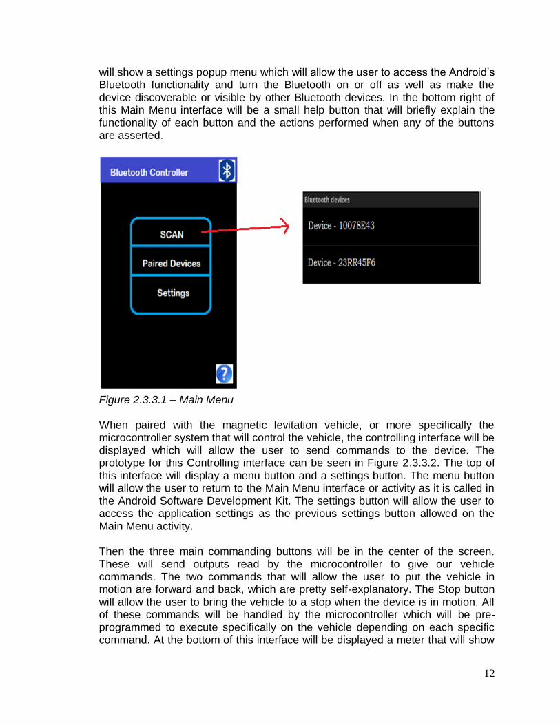
Bluetooth Profile For the application to be able to use the features of this library, at least one of the two Bluetooth permissions needs to be declared: BLUETOOTH and BLUETOOTH_ADMIN. The BLUETOOTH permission is used for connection purposes such as requesting and accepting a connection as well as transferring data through the connection. BLUETOOTH_ADMIN must be declared in order to manipulate the settings for Bluetooth that are already incorporated in the smartphone device. Through this permission, the application can put the device in device discovery mode. This mode will actually allow the smartphone to search for as well as be found by any Bluetooth enabled devices within the probable range. After filtering the main functionalities of the application, a user interface needs to be designed to integrate these functionalities. The application’s interface is designed using XML (Extensible markup Language) and the Android Development Tools downloaded for the Eclipse Environment. These tools allows developers to design the interface of the application by either simply dragging and dropping, using the cursor and changing widget displays, by using the side menus, or by editing the actual XML code behind the interface. By manually dragging and dropping, etc. the XML code gets edited simultaneously and accordingly to the changes in the display. For the main interface, the group will design a main menu that will have three main buttons and an additional help button. A prototype of the main user interface can be seen in Figure 2.3.3.1. The first button, Scan, will be used to scan for devices with Bluetooth integration. It will display a list view of all devices in range and viewable by our application. Each device shown by this button will be clickable and upon selection the user will be prompted to pair with the device, giving a success or error message when done depending on whether the external device was successfully paired with our Android device. The second button will allow the user to also see a list view similar to the one seen by scan, only this will show the devices that the smartphone is already paired with. This list will also show clickable devices which will allow the user to disconnect from that paired device or to establish communication between the already paired devices and be able to send data through the formed network. The last button
12
will show a settings popup menu which will allow the user to access the Android’s Bluetooth functionality and turn the Bluetooth on or off as well as make the device discoverable or visible by other Bluetooth devices. In the bottom right of this Main Menu interface will be a small help button that will briefly explain the functionality of each button and the actions performed when any of the buttons are asserted.
Figure 2.3.3.1 – Main Menu When paired with the magnetic levitation vehicle, or more specifically the microcontroller system that will control the vehicle, the controlling interface will be displayed which will allow the user to send commands to the device. The prototype for this Controlling interface can be seen in Figure 2.3.3.2. The top of this interface will display a menu button and a settings button. The menu button will allow the user to return to the Main Menu interface or activity as it is called in the Android Software Development Kit. The settings button will allow the user to access the application settings as the previous settings button allowed on the Main Menu activity. Then the three main commanding buttons will be in the center of the screen. These will send outputs read by the microcontroller to give our vehicle commands. The two commands that will allow the user to put the vehicle in motion are forward and back, which are pretty self-explanatory. The Stop button will allow the user to bring the vehicle to a stop when the device is in motion. All of these commands will be handled by the microcontroller which will be pre-programmed to execute specifically on the vehicle depending on each specific command. At the bottom of this interface will be displayed a meter that will show

13
the vehicles speed as it moves about the track. The speed will be displayed in mph (miles per hour).
Figure 2.3.3.2 – Controlling Interface Speed will be calculated by repeatedly prompting the Bluetooth module on the microcontroller for the vehicles location on the track and using the measured time on the smartphone, thus allowing the team to use the displacement divided by time, and giving our velocity.
v = Δs/Δt With the microcontroller keeping track of the location of the vehicle in reference to the track, and the smartphone keeping track of the time, the team will be able to calculate the speed of the vehicle during its movement about the track. These variables will begin to get calculated as soon as a directional/motion button (Forward/Back) is pressed and will cease to calculate when the velocity reaches 0 mph or when the vehicle’s displacement is equal to zero. The microcontroller will have preprogrammed dimensions of the track. The displacement will be calculated in accordance to the magnets and their specific location on the track. The magnets will be about an inch in length. Every time the vehicle crosses a magnet, the displacement will be updated to the microcontroller. This information will in turn be sent to the Android application for processing of speed. The time will then be measured from initial touch of the motion buttons in the application and updated every time a displacement is received. Starting time calculation and ending at every displacement interval measured.

14
3.0 Research 3.1 Bibliography of Related Work When considering building a magnetic levitation vehicle, the group was aware of different projects that have done this project before. With transportation through levitation being a very interesting subject, there have been numerous attempts to provide a transportation that moves based on magnetic force propulsion.
3.1.1 Linear Motor for Maglev Train 1997 W. Beaty
One of the most famous ideas is that of science hobbyist William Beaty. His design of the magnetic levitation vehicle is based on hall sensors, and a circuit consisting of transistors and diodes. Each sensor controls the polarity of each electromagnetic coil and vice versa the coils affecting each sensor. The sensors reverse the polarity of the magnet when it changes thus creating a zero magnetic field. The point is that this will allow superconductive levitation where the coil assemblies repel bar magnets regardless of polarity. William Beaty also writes about how one can add an electrical drive motor to the magnetic levitation vehicle. The linear DC motors are composed of three parts:
1) A long magnetic track 2) A moving coil 3) A “commuter” to reverse the poles of the coil.
The key is to apply sideways thrust to the vehicle by switching polarity on the coils. The next system involving related work is heavily based on William Beaty’s article and work done.
3.1.2 Antipodes Magnetic Levitation Vehicle This design is a remote controlled, 3-phase, 6-solenoid motor with electromagnetic propulsion system done by an FTC World Championship team. This system was built and designed by the team and based on William Betty’s 1994 article mentioned above. This team had two parts to their electronic system consisting of the motor controller and the remote. The remote is an Xbee antenna mounted on an Arduino Prototyping shield which is mounted to the Arduino Uno R3 microcontroller and powered by a 9 V battery. An encoder is also mounted and used for the users input.
15
The motor controller carriers an Xbee antenna mounted on an Arduino Prototyping shield as well. They in turn have two Sparkfun Ardumoto Shields, which are mounted on a separate Arduino Uno R3 and powered by an 11.1 V Lithium Polymer battery. The motor shields in this project are used for sending current to the vehicle in either direction. The three Hall-effect sensors provide the three phase system and give measurements to the controller. The track is made of wood and Plexiglas and of course different magnets and spacers to go in between magnets in a Hall Bach array like manner. Their vehicle is composed of Lego parts and some aluminum material. Communication and propulsion is done through the Hall Effect Sensors where the microcontroller is programmed to read the location specifically on the track and send it to the remote. The communication between the analog remote controller and the systems controller occurs through an adjustable, analog knob. The control is made of Plexi glass for protection of its internal components. This remote controller controls not only the acceleration of the vehicle but the braking system as well. By making an analog remote, they simplify the speeding and braking of their system by adjusting the knob for acceleration and returning the knob to its original stable position for braking. Turning the knob in either direction puts the vehicle in motion in either direction as well. Since our team is to use a remote controller for the system with digital inputs to the vehicle’s micro controlling unit, adjusting speed and braking would be a challenge that was definitely undertaking. The other biggest difference aside from the choice of a remote controlling device is the track. The Antipodes team built a horizontal track while our project’s design involves a circular track. This also will present diverse challenges since the team will encounter different situations in the turning of the vehicle, where other similar projects and work was based of a linear track and no need for turning of the magnetic levitation vehicle was necessary.
3.1.2 Small-Scale Maglev Train Another design similar to the project at hand is a small-scale version of a magnetic levitation train done by a senior design group from Georgia Tech. In this system, this group attempts to design a smaller version of a magnetic levitation train that would be a prospective technology in the real world of transportation. This group uses a small train car, a track with a magnetic strip, neodymium sik magnets for propulsion and levitation purposes, a linear synchronous motor, AC drive for the variable three-phase current source, an AC reactor, and resistors. There system reaches levitation of 2-4 mm above the track and a speed of 1

16
mph. Braking is induced by decreasing the frequency of the AC drive. This Georgia Tech group’s main goals were to:
- Power the AC Drive to provide the variable 3-phase current - Setting the switch to control direction of flow of current in the LSM - Gently pushing the train car to provide an initial momentum - Controlling the frequency on the AC Drive to provide
acceleration/deceleration
There system or more specifically there vehicle was physically powered or pushed on initial demonstration to get the vehicle in motion. No remote controller was used to initiate the vehicle’s movement across the track in comparison to the Antipode team, where an analog remote controller with antennas was used to communicate with the vehicle.
Conclusions on Related Work
Most of the related work and projects use similar features of the magnetic levitation design and basically all consist of the same foundation. Where levitation is achieved through magnetic polarity and maneuvering the solenoids through some sensors to achieve propulsion or movement about a track. The group decided to take all these ideas together and add its own features as well as approaching certain sections differently by using some of the latest technological updates.
3.2.1 Microcontrollers and Boards
We decided our design would need a microcontroller. The microcontroller’s ability to obtain information and control our car via wireless control is an integral feature our group decided we would need. We had multiple requirements and many microcontrollers to choose from. We had to consider which features offered by each of these Microcontrollers in order to decide which one to use. First, we chose features that we knew would be a requirement for the project, then we compared that to the microcontrollers we had available. Microcontroller Requirements and Preferences
Input / output ports and pins
RF radio, Bluetooth
Brand each group member feels works best.
Architecture
Dimensions
Optimal Cost
Analog / digital converter if needed
Voltage and current usage
Programming language requirements

17
Compiler program availability
Compiler versatility
Memory Usage o ROM o EPROM o EEPROM o Flash
Frequency requirements
Ease of use
Documentation
Once we understood what we needed our microcontroller to do, we looked into multiple Microcontroller units to see which one would fit our needs the best. One of the Microcontrollers we selected was the Arduino Uno Revision 3 board which uses an ATmega328 microcontroller. Another Microcontroller and board we were looking at was the MSP430. Input / Output For our microcontroller, the amount of inputs and outputs available is a big deal. In this case, we have to make sure our microcontroller will be able to handle the number of inputs and outputs our project requires. When looking into the Atmega328 we can find that the there are 14 digital Input / output pins and 6 analog Input / Outputs. We can see that on the msp430 there are 6 digital I/O ports, each of these ports supporting 8 digital I/O pins. As we can see here, the msp430 wins out having the larger number of possible inputs, since our project doesn’t seem to need analog ports for basic function. RF Radio or Bluetooth Obviously none of the microcontrollers were going to have an integrated wireless communication function already on board, but this was still a call for concern since we knew our project would be controlled wirelessly. Since we knew this is a requirement for our project, we wanted to make sure there was a popular piece of hardware that was configurable with the current model of MCU we choose. For the msp430 and the ATmega328 we have the very popular RN-42. Since both are compatible, the only distinguishable feature is the amount of information on configurations and programming. Brand Obviously brand is going to be a consideration. In this case since we have knowledge of the MSP430 having used it before, this is the one we were leaning towards. That being said, the most descriptive project that we found, which had a very huge impact in our design, uses the ATmega328 with the Arduino Uno Revision 3 board. Obviously we will choose the one that fits the projects needs, but one of the needs is for the group to be able to use it properly.

18
Dimensions Dimensions refer to the board more than the microcontroller. The board we will eventually use has to be small enough to fit on our vehicle, but also large enough to be able to configure all the wiring we need. At this specific time, I do not know every requirement that exists in terms of how large it must be, but because of the vehicle size limitations we have a maximum size of the board. Our car should not be larger than 8-10 inches long and 3-4 inches wide, depending on track size. This means that when our board is placed on the car, along with other components, it has to be small enough to fit. I estimate that our board should not be larger than 5 inches long and 3 inches wide. Given that a majority of premade boards are much smaller than these requirements, our requirements should be met. Optimal cost
Optimal cost is pretty self-explanatory; we must make sure that the microcontroller and board meet the requirements without going overboard to increase cost. This means that we don’t need to spend a ton of money on a ridiculous microcontroller that exceeds our project expectations because we can. We have to find the cheapest one that meets our requirements. This also refers to components that might be included in the board and MCU such as a Bluetooth device. If an integrated board, wireless device, and MCU package is cheaper than buying the parts individually, it might be considered. Analog / digital converter
As of right now, we will have analog inputs. This means that our car will need analog inputs to work with the Hall Effect sensors. Most of the msp430 parts do not support analog naturally, which means we will have to narrow the search to correctly find a specific model. Since that greatly limits the number of models we are able to look at, it changes what our group might have been thinking for the MCU. Since the arduino board with the ATmega328 has 6 analog inputs ready, it already complies with the requirements. Voltage and current Since our power supply will be on the vehicle, we need to know what the MCU’s requirements are. The Atmega328 has a “Built-in 100 mA, regulated power supply that accepts an input voltage ranging from +7v to +24v.” This also has a +5V output. The MSP430 site says “1.8 – 3.6V operation” which is significantly lower than the Atmega328, which might mean that we could use more of our power source for moving the vehicle rather than the control system. Compiler program Obviously our ability to program the MCU is of huge importance. This means that the MCU we choose must have readily available programming software. Along with it being available, it should be cost efficient and usable by the group members.

19
“The Atmega328 has been designed to use work with the Arduino IDE v1.0.x, which is available free at http://arduino.cc/hu/Main/Software.” Since this is free, and easily downloadable, it meets our requirements for accessibility. Unfortunately none of the group members have used the software so we would have to learn. Since the group has already used MSP430 we are well aware that code composer studio on campus is readily available. Along with it being readily available, we all have used it in previous classes so therefore can expect to understand all of the features. Memory usage
Knowing which memory can be used and how much is available is a feature we also must consider for choosing which microcontroller unit to choose. The ATmega328 has its memory listed as;
32KB of flash memory
2KB static RAM
1KB EEPROM There are multiple msp430 models for choice up to
64KB of flash memory
10KB static RAM
8KB EEPROM Obviously we do not have such high memory expectations, but when finalizing our choice for which MCU’s it’s good to know what available. Documentation The documents available for each microcontroller are useful for reference material on understanding how it works. If there isn’t very much documentation for a product, then our ability to use it in the project will be limited to what we can learn. With the ATmega328, the user manual is very understandable and well laid out, but somewhat limited in terms of how much information is actually given. On the other hand, the MSP430 user guide is much longer with descriptive details about every feature of the MSP430. Even though it is much more detail, it is not laid out as understandably in terms of use. It doesn’t have the same description. Ease of use
Knowing how easy it is to use each of the MCU’s along with each of the board possibilities is very important. If we cannot get our microcontroller to work, the whole project will not work. Knowing how to use the compiler in order to program our microcontroller is essential. Having to learn a new program for the Atmega328 is going to be a task, whereas in the MSP430 we already know code composer studio so we can handle programming it. Also having the correct

20
schematics for each of the ports of the microcontrollers is essential. We will need to understand all of these things to make the best decision.
3.2.1.1 Atmega328: Other features We plan on using each one of the features available for a specific part of the project. As we said earlier in the project, optimization comes from using each of the possible features to its optimal potential. This choice was made simply because our group was on a budget and we knew it was necessary to spend the least amount of money but still accomplish all required tasks. Memory The 1k bytes of EEPROM memory will be used to store constant values regarding the distances between magnets and other distances that are crucial to the design but also that might be changed as time goes on. This will also be used to control the variable leading to connection with the Bluetooth device. Since we will possibly want to switch cell phones at some points, we would like to be able to slightly adjust this in the memory. The Flash memory allowed by this microcontroller will allow us to save our program to the device. It is large enough to sufficiently control all aspects expected of this project, and possibly more as we move through. 5V output At first this was an ignorable feature involved in this design. Once our design move forward this feature gave our group and easy and efficient source that could power each of our sensors and other microchips. Instead of using complicated wiring and taking up more space than needed, the 5v output condenses those hassles into one simple port. Analog inputs
Our design requires Hall Effect Sensors to help us control the vehicles movement. The Arduino Uno rev 3 comes with analog inputs that are perfect for this specific use. Other models of microcontrollers did not come with these. Our Hall Effect sensors will be utilized to their fullest potential with the standard analog input pins. Digital inputs Since we will need to send our H-bridge switches signals, the multiple digital inputs will definitely be utilized. We have to make sure our all of those are heading to the correct place. Also, the digital inputs will have to be used in order to connect the Microcontroller to the phone using the RN-42 to connect wirelessly. This will use the rest of the inputs and outputs for the digital section of the MCU

21
3.2.1.2 RN-42 The RN-42 is a device used to connect through Bluetooth. Since this device was so popular in t he hardware community, it was an easy choice for the group. We knew that with its popularity there will be a large amount of resources to learn how to use the device. Also the popularity could hint toward the quality of the device being better than its competitors. This device is programmed by simple ASCI command language.
Figure 3.2.1.2a- RN-42 Block diagram
When we configure the RN-42 we will be able to the LAN default settings of:
• Baud rate 115,200 • 8 bits • No Parity • 1 stop bit • Hardware flow control enabled
We will need to follow the configuration settings in order to establish a connection between the device:
Table 3.2.1.2a- Configuration Values

22
Along with the configuration timers, we will need the PIO and DIP switches configuration:
Table 3.2.1.2b- Switch and Pin Setup
Once we have the RN-42 configured and ready to operate we simply have to list a few commands using the list found in the user manual in order to operate appropriately in the system. Also knowing which of the pins will be connected to which I/O of the MCU will be an essential part of the Maglev control.
Figure 3.2.1.2b- Pin Diagram
The transmitter will easily have enough range to control the maglev. The data sheet says 55 ft after one wall, and because we never plan on being between a wall or more than roughly 10 feet away, our design should be able to work
perfectly.

23
3.2.1.3 RN-52 The other popular device we have available for wireless communication is the RN-52. This is obviously the later version of the previously described RN-42. Since we’re looking for the most efficient part we could be using for this project we needed to do research on this part. This device will be used to connect to Bluetooth as required by the project.
1-1: GENERAL SPECIFICATIONS
Specification Description
Standard Bluetooth 3.0, class 2
Frequency Band 2.4 ~ 2.48 GHz
Modulation Method GFSK, PI/4-DQPSK, 8 DPSK
Maximum Data Rate 3 Mbps
RF Input Impedance 50 ohms
Interface UART, GPIO, AIO, USB, SPI, speaker, microphone
Operation Range 10 meters (33 feet)
Sensitivity -85 dBm at 0.1 % BER
RF TX Power 4 dBm 1-2: WEIGHT & DIMENSIONS
Specification Description
Dimensions 26.0 mm x 13.5 mm x 2.7 mm
Weight 1.2 g 1-3: ELECTRICAL CHARACTERISTICS
Specification Description
Supply Voltage 3.0 ~ 3.6 V DC
Working current Depends on profiles, 30 mA typical
Standby current (disconnected) < 0.5 mA
Temperature -40ºC to +85ºC
ESD JESD22-A224 class 0 product
Humidity 10% ~ 90% non-condensing Using the specs above, we can see that the RN-52 meets all the requirements of our project. The dimensions are small enough to fit on the maglev vehicle but not too small to balance safely. The weight is not too heavy and will not limit the movement of the vehicle. The voltage and current characteristics fit the design perfectly and will allow for easy implementation. An operation range of 10 meters will be more than enough to control the device successfully. The functioning temperature will easily stay inside the required functioning temperatures. With all

24
of the difference interface possibilities we know that we will be able to connect efficiently.
Figure 3.2.1.3a- RN-52 Pin Diagram
Pin Symbol I/O Type Description Direction Default
1 GND Bidirectional with programmable strength internal pull-up/down
ground
2
GPIO3
Bidirectional with programmable strength internal pull-up/down
This pin enters device firmware update (DFU) mode at bootup if a USB device powers VBUS. GPIO3 requires 47 kΩ to ground and 22 kΩ to the USB VBUS signal if the USB VBUS is supplying power to the main board.
Input Low
3 GPIO2
Bidirectional with programmable strength internal pull-up/down
Reserved, event register. Toggles from high to low for 100 ms to indicate that the module’s state has changed. A microcontroller can enter
Output High

25
command mode and poll
4 AIO0
Bidirectional Analog programmable input/output line.
I/O
5 GPIO4
Bidirectional with programmable strength internal pull-up/down
Factory reset mode. To reset the module to the factory defaults, GPIO4 should be high on power-up and then toggle low, high, low, high with a 1 second wait between the transitions.
Input Low
6 GPIO5
Bidirectional with programmable strength internal pull-up/down
Programmable I/O.
I/O High
7 GPIO12
Bidirectional with programmable strength internal pull-up/down
Programmable I/O.
I/O High
Pin Symbol I/O Type Description Direction Default
8 GPIO13
Bidirectional with programmable strength internal pull-up/down
Programmable I/O.
I/O High
9 GPIO11
Bidirectional with programmable strength internal pull-up/down
Programmable I/O.
I/O High
10 GPIO10
Bidirectional with programmable strength internal pull-up/down
Programmable I/O.
I/O High
11 GPIO9
Bidirectional with programmable strength internal pull-up/down
When you drive this signal low, the module’s UART goes into command mode. If this signal floats high, the UART is in data mode. Reserved. Not available for use at runtime.
I/O High
12 USBD-
Bidirectional USB data minus I/O
13 USBD+
Bidirectional USB data plus with selectable internal 1.5-Kohm pull-up resistor
I/O
14 UART_RT
S
CMOS output, tri-state, with weak internal pull-up
UART request to send active low.
Output
15 UART_CT
S
CMOS input with weak internal pull-down.
UART clear to send active low
Input
16 UART_TX
CMOS output, tri-state, with weak internal pull-up
UART data output
Output
17 UART_RX
CMOS input with weak internal pull-down.
UART data input
Input
18 GND
Ground
Ground
19 GPIO7
Bidirectional with programmable strength internal pull-up/down
Driving this pin low sets the UART baud rate to 9,600. By default the pin is high with a baud rate of 115,200.
I/O High
20 GPIO6
Bidirectional with programmable strength internal pull-up/down
Programmable I/O
I/O High
21 PWREN
Analog Pull high to power up RN52
22 VDD
3.3-V power input
3.3v power input
Table 3.2.1.3b - RN-52 Pin table
Using the Pin Diagram above we will be able to setup our hardware efficiently.

26
Comparison Since we have two options we have to figure out which one serves us better. Using the research our group has found, we can understand that both will be able to successfully complete the task of connecting our vehicle to the Bluetooth controller. Since neither the RN-42 nor the RN-52 will fail to meet basic requirements such as dimensions or functionality we have to look into costs and ease of use. The RN-42 costs $15 while the RN-52 is reaching upward towards $25. This means that we could save $10 using the RN-42. That being said, the RN-52 has much more documentation on use and setup. Also the setup seems to be much simpler and will be more effective. Since our group is only saving a total of $10 by using the RN-42, it seems as though it is worth it to reach for the RN-52 instead. The effectiveness of the RN-52 seems to be superior to the RN-42 enough for us to choose the RN-52.
3.2.2 Application Development Application development plays a key role in this project since the application will be the main interface between the user and the system as a whole. There is the option of doing an application for a MAC laptop or a Windows 8 Operating System laptop. There is also the option of developing a smartphone application for a cellular device or developing a web application. Given that a smartphone is a more feasible and portable device, not to mention the growing popularity of its expanding capabilities, the application was to be developed on a smartphone. There was the option of diving into the field of application development in either of the two leading smartphone producers of our generation, which includes the Android and the iPhone. One of our group members had developed for the Android Operating System previously, which was an advantage to choosing an Android device, yet there was an iPhone testing device that would be available to test with our system making our decision in need of in depth research into each field of smartphone application development. Before the decision of device was made, we also needed to know how we were to integrate the smartphone as a controller for our system and communicate as a peripheral with our magnetic levitation vehicle on the magnetic track. In order to send inputs and outputs or commands from our smartphone we needed a method or channel through which communication/execution of these commands were to take place. There was the option of using Wi-Fi versus Bluetooth as a means to communicate between the controller, our smartphone, and the controlling system of our vehicle, the microcontroller.

27
3.2.2.1 IPhone Development
Our first initial inclination was to use the iPhone as the remote controller to our system. After plenty of research, we found many obstacles in developing the application in the iPhone Operating System. When looking into iPhone application development, one must have the right tools to even begin. The only suitable Integrated Development Environment (IDE) for Apple, the company behind the iPhone, to be used if one wanted to become a developer for the iPhone Operating System is called Xcode. Now this software can only be run in the Mac Operating System, which means we need to have a Mac laptop or have access to one. None of our team members owned a Mac laptop to begin with. After this issue can be overcome, there is the next obstacle of becoming familiar with Xcode and the coding language used for development. The main coding language used in Xcode is Objective-C, another technology our team was unfamiliar with. Although Xcode does allow integration using other languages such as C++ or Java, languages that the team was familiar and had previous experience with, this would surely bring about issues when it came down to integrating the source code since these were not Xcode’s native language. To reiterate, the team first needed a Mac laptop to run our Xcode IDE, then there was the issue of learning and troubleshooting with a whole new language called Objective-C. After further research, the team found that Apple disproved of using their devices, such as the iPhone, to interact with other peripherals that were not made by Apple. This meant that there were very little sources to help us with our application since our remote controller would be interacting with an external microcontroller, not made by Apple. Unless one became part of Apple’s MFi licensing program which allows access to the hardware components, tools, documentation, technical support, and certification logos needed to create AirPlay audio accessories and electronic accessories that connect to iPod, iPhone, and iPad. This was an expensive program designed for companies wanting to interface their technologies or devices with Apple’s products, and was not what a senior design group was looking for. Furthermore, in order to access the iPhones Bluetooth capabilities from the application, the external device or peripheral had to support Bluetooth 4.0 Low Energy (LE) devices. This would limit our choice of a microcontroller and force us to choose one that might not be the best fit for our system. Using the iPhone as a remote controller meant we needed to buy kits that were specific to iPhone interaction and therefore more expensive. When it came down to testing, that is where the team believed had the upper hand since we had an iPhone 5, one of Apple’s latest developments. In order to test our application there was an emulator that simulated the iPhone environment and had most of the capabilities that an actual iPhone would have. For the

28
magnetic levitation system, we needed the actual smartphone as the remote controller for the vehicle, not a simulated one, which was fine for initial testing purposes. Testing our application on our iPhone brought another issue with Apple. For a developer to test their application using Xcode, you had to become part of Apple’s developer program which cost $99 for a year. Although this was a cost that could be overcome and might be worth its value, the fee was still a cost that would be factored in our budget. After all of these obstacles were considered, the team now looked into the Android Operating System and its application development.
3.2.2.2 Android Development Developing for the Android OS is a completely different scenario. As far as the tools and environment, Android allows you to use just about any Operating System which means any laptop can be used as a viable tool to develop an Android application. This was the first obstacle faced with iOS development. The next step is to choose an Integrated Development Environment. When it comes to Android, the team had more than one choice, with IntelliJ and Eclipse being the most probable choices. Since the team was familiar with the Eclipse Environment and the Android Developers site suggested Eclipse, that’s what the team chose. The Android SDK also came with an emulator that would simulate the android OS on the computer used for development. In order to start developing an Android app, a version of Eclipse was needed, and then the team was to download the Android SDK (Software Development Kit). After this the ADT (Android Development Tools) for Eclipse needs to be installed and the latest SDK tools and platforms are to be downloaded using the SDK manager already installed with the ADT. All of these steps are seem simple and more familiar since Eclipse is an IDE the team was familiar with. Java vs Xcode The main programming language that will be used is Java and as mentioned earlier, this is a technology the team had experience with in contrast with a brand new IDE and programming language such as Xcode and Objective-C. Both of Java and Xcode provide the use of Object Oriented programming design. Java however is more of a class based language which allows for more organized programming. Objective C is an extension of the C language with what they call smalltalk. Smalltalk gives the use to objects to:
Hold state (references to other objects).
Receive a message from itself or another object.
In the course of processing a message, send messages to itself or another object.
This implementation of objects is also available in Java. Although Java does derive many of its’ syntax from C, it brings a completely different programming

29
language, being designed to have as few implementation dependencies as possible. References for the Project
As far as source code examples and interfacing the Android smartphone with external devices, such as in our case, a microcontroller, this was a definite plus. Plenty of examples and guides were found that would help our development in the Android OS. In contrast to iPhone and Apple, Google, the maker of the Android smartphone, actually has numerous tutorials on interfacing with different external devices and accessing the Bluetooth capabilities of the phone. This is important to our system since we will be able to gather information and have a better picture of the interaction that will happen between the smartphone and the microcontroller as well as the type of commands the smartphone will be sending. Not only are there general examples of using similar functionalities that will be needed from our Android smartphone, but there are also specific examples for interfacing with the specific Atmel Atmega Arduino uno microcontroller we will be using in our system. This provides us with ample sources that will save time when troubleshooting and debugging our application. Testing
Again, to test our application the group needs to know that all the functionalities work on a real device. This is where the challenge was since the team did not have an android device. When comparing to iPhone development, the team needed a cost of $99 to test the application. So analyzing the advantages of the Android development thus far makes it worth acquiring an Android smartphone or investing in one. When a device can be acquired, the team was able to test the application on a real device. In order to do this, USB debugging needs to be enabled on the device. This can be done on Android 4.2 versions and newer, by going to
- Settings - About phone - Build number - tap seven times - Developer options (hidden by default)
When you return to the previous screen, the Developer options can then be seen. After plugging the device on the computer used for development, the Operating System on the computer will install the necessary drives for the smartphone. When the application is built and run, the application will then appear on the device and can be tested. Running the application on a real device provides better debugging benefits than on the emulator provided by the Development Tools since the real device is what will eventually permanently host the application. Android development provides many advantages to the developer and encourages coders to use their tools by providing numerous source code

30
examples for a variety of different projects. Table 5 shows the main differences that compelled the decision between which application development technology to choose. In the end the team believed developing the controlling application was better benefitted by using the Android Operating System on an Android powered smartphone. Since the purpose of the application is to interface through Bluetooth, the Android development was the best option. These specifications shown in the Table 5 list the most important and pertinent areas of interest that were considered for the purposes of this specific project. These are the areas that would have the greatest impact on the magnetic levitation system that is to be designed and created for this project. Only the two most prominent and well known technologies, Android and Apple, in this area of application development were considered due to both having the ability to accomplish the task.
Android vs iPhone Development Table Android Apple - iPhone
Tools Any Laptop, any OS Only Mac
IDE Eclipse, IntelliJ, Netbeans Xcode
Programming Language Java Objective-C
Interfacing with external
Devices
Very open Mostly Apple only devices
Bluetooth Support Any Bluetooth enabled device Only devices supporting
Bluetooth 4.0 LE
Example Source Code
Related to Project
Numerous Examples Very few
Interface development Less User friendly More user friendly
Testing on Real Device Free $99 and must join Apple
Developer Program
Table 3.2.2.2
31
3.2.2.3 Android Smartphones The remote controller has to be updated with the latest technology based on the group’s project intentions. Since the group is using an Android powered smartphone to act as the remote controller for the system there are many phones to consider. Of the latest smartphones released that run the latest Android version of open GL, 4.3, there were three prominent choices out there. These are the HTC One, the Samsung Galaxy Note 2, and the Samsung Galaxy S4. All three of these present prominent choices for use with our system. Analyzing all of their features, the group understands that the most important features are those of its Bluetooth capabilities and processing speed. HTC One
The HTC One brings a 4.7 inch screen for user interfacing with the Operating System. It carries a 1.7 GHz quad-core processor for processing speed and power and its one of the first of its kind to bring four cores to the CPU. The Bluetooth capabilities of this phone are the latest, which is Bluetooth 4.0 Low Energy. Which means the group will be getting the best out of the phone. Samsung Galaxy Note 2 The Samsung Galaxy Note brings for the about the biggest user interfacing screen out of all three smartphones in comparison with an almost six inch display. It also has a 1.6 GHz quad-core processor for speed and usability. Looking at its Bluetooth capabilities, the Note 2 also comes with Bluetooth 4.0 Low Energy. In essence the only significant difference with the other phones was its screen size. Samsung Galaxy S4 The Galaxy S4 is the latest in Samsung’s smartphone technology. It has a 5.38 inch screen, significantly bigger than the HTC One, but at the same time much smaller than the Galaxy Note 2, also carrying a quad-core processor but a bit faster that the HTC One and the Galaxy Note 2. The processor speed is 1.9 GHz outrunning the HTC One by 200 Hertz and the Galaxy Note 2 by only 300 Hertz. When it comes to Bluetooth Technology, the Galaxy S4 also carries the latest Bluetooth 4.0 Low Energy technology. In essence, there was no major difference between these three phones as seen for prospective remote controllers for the group’s magnetic levitation system. The essential features and specifications brought were equally capable to carry out the task for which the group intended the remote controller to do. So deciding on which smartphone to choose for the team’s remote controller was basically based more on individual opinion. The features or a specification that would have the greatest impact on the group’s system is the Bluetooth capabilities and the processor speed. Looking at each smartphone’s Bluetooth capabilities, it can be

32
seen that all of the smartphones bring forth the latest version of Bluetooth which is Bluetooth 4.0 LE (Low Energy). So now it was a matter of the processor speed, as the processor would play a role in the user responsiveness and processing of the sending and retrieving data. Although the Samsung Galaxy S4 had the fastest processor, the others were not too far behind. The matter came into really just choosing individual preferences as mentioned earlier. The outcome was the Samsung Galaxy S4, which dealt mostly on those extra two or three hundred Hertz of processing power.
3.2.3 Wireless Communication Wireless communication is a growing field with more and more technologies available for this form of communication including infrared, Wi-Fi, Bluetooth, and other relevant technologies. For the magnetic levitation system that the group proposes to design, two of these technologies are the most prominent and best suited for this type of system. These are both Wi-Fi and Bluetooth Wireless Communication. Both of these technologies provide an ample medium through which the remote controller and the system can communicate.
3.2.3.1 Wi-Fi Connectivity Wi-Fi is a wireless communication standard that uses radio frequencies to establish connections. Wi-Fi has had the main purpose of connecting devices to the internet. Since the smartphone has Wi-Fi capabilities, this would be a prospective connection to use to communicate with the vehicle’s microcontroller. Using Wi-Fi would limit the connectivity to the Wi-Fi connection strength and signal depending on the testing environment in which the system is not only tested, but presented as well. Although Wi-Fi allows for longer ranges of interfacing between systems or devices, ranges such as 300 feet from the networking node, this is not really a pro with this particular system. The user in this system will not be any farther from this system than a probable 10 feet, making this Wi-Fi advantage over Bluetooth a light one. Wi-Fi connectivity can be seen as more secure network with numerous securities. Yet again for this system, this is not a heavy advantage since the system’s focus is not on security, but communication and interfacing between a remote controller and a wireless enabled micro controlling hardware.
3.2.3.2 Bluetooth Connectivity Communication between our smartphone controller and our magnetic levitation vehicle system will happen through a wireless Bluetooth connection between the smartphone and the microcontroller. Bluetooth is a low-power, wireless and

33
automatic, radio frequency standard. It will allow our smartphone to use as little power needed to send commands to our microcontroller. Our Bluetooth connection between our remote and our system will allow for as minimal interruption as possible given the technological advances today using a communication frequency between 2.402 GHz and 2.480 GHz, which has been set aside by international agreement for the use of industrial, scientific and medical devices (ISM). Our smartphone will send out a small signal of about 1 milliwatt, limiting the range of connection between our remote and vehicle to about 10 meters or 32 feet. This will further limit the odds of other devices in the area of testing or presentation that might have the ability to interfere with our system and device, yet it is also a good enough range to where the user will not have to be directly next to the system, more specifically our magnetic levitation vehicle. Since our vehicle will be moving about a circular track with a radius of 0.75 feet, the range in our Bluetooth connection will allow a sufficient testing distance. In the case where there might be other devices, such as other smartphones which will be likely, with a Bluetooth capacity, the Bluetooth connection uses spread-spectrum frequency hopping. This approach will isolate our system from any external devices since our connection will use about 79 discrete and randomly chosen frequencies within a chosen range and will be switching between these frequencies consistently. So our transmitters will change frequencies 1,600 times every second. Given that other Bluetooth devices that might be in range use this method of interaction, any unlikely interference will at most last but a fraction of a second. To further isolate our system, Bluetooth allows detection for individual or certain addresses, thus when our remote (smartphone) and our vehicle are in range, they form a small network. So, in the case that another device is in range and transmitting a Bluetooth signal, our system will ignore this interference being that it will not be within our systems network. Other choices of wireless connectivity include Wi-Fi, yet the reason our system will communicate via Bluetooth is mainly due to low cost and bit rate. Wi-Fi allows a faster connectivity yet, when it comes to communicating, Bluetooth has Bit-Rates of about 2.1 Mbps while Wi-Fi is in the range of 600 Mbps. A comparison chart between Bluetooth connectivity and Wi-Fi connectivity can be seen in table 4 to further emphasize the differences between each technology.

34
Comparison chart – Bluetooth vs Wi-Fi
BLUETOOTH WI-FI
Frequency: 2.4 GHz 2.4, 3.6, 5 GHz
Standard: IEEE 802.15 IEEE802.11
Cost: Low High
Bandwidth: ( 800 Kbps ) (11 Mbps )
Specifications Authority: Bluetooth SIG IEEE, WECA
Security: It is less secure It is more secure
Year of development: 1994 1991
Primary Devices: Mobile phones, mouse,
keyboards, office and
industrial automation
devices
Notebook computers, desktop
computers, servers, TV, Latest
mobiles.
Hardware requirement: Bluetooth adaptor on
all the devices connecting with each other
Wireless adaptors on
all the devices of the network, a wireless router and/or wireless
access points
Range: 5-30 meters With
802.11b/g the typical range is 32
meters indoors and 95 meters
(300 ft) outdoors. 802.11n has greater range. 2.5GHz Wi-Fi
communication has
greater rangethan 5GHz.
Antennas can also increase range.
Power Consumption: Low High
Ease of Use: Simple to use. Can be used
to connect up to 7 devices
at a time, easy to switch
between devices or find
and connect to any device.
It is more complex and requires
configuration of hardware and
software.
Latency: 200ms 150ms
Bit-rate: 2.1Mbps 600 Mbps
Table 3.2.3.2 (Reprinted with permission from diffen.com)

35
3.2.4 Electromagnets Linear motion will be achieved through the use of electromagnets. An electromagnet can be created by simply connecting a current source to both ends of a conducting wire, which will induce a magnetic field around the wire. This project will use electromagnets to propel our vehicle forward with a steady acceleration to achieve a velocity of around 1mph. A key difference between electromagnets and permanent magnets is that the polarity of electromagnets can be manipulated to the user’s preference. Understanding the properties of the magnetic field created is essential to design of the electromagnets. The properties governing the electromagnets are the magnetic field B and the magnetic force H, since the magnetic force deals with the lifting power of the magnets that will be left to discussion in a later section. The two variables are interrelated with the permeability of the surrounding medium. For free space the relation looks as follows
Both the force and magnetic field are circulatory around the copper wire. Using the right hand rule for magnetism the direction of the magnetic field can be deduced from the conventional direction of the current flowing through the wire. Electron flow is different than the flow of electrons. Reversing the direction of the current will result in a change of direction in the magnetic field. This concept understanding will be ideal when designing the circuitry for magnetic field polarity detection and reversing the current when needed. To amplify the magnetic field intensity we need our conducting wire to be tightly spaced as shown in Figure 1 below in Microsoft Paint. The magnetic field lines are shown wrapped around the conducting wire.
Figure 3.2.4: Magnetic Field intensity resulting from close placement of conductors

36
The intensity is nearly doubled when conductors with the same current flowing through them are placed in close proximity of each other. Source:
3.2.5 Solenoids The electromagnet configuration for our project will consist of three solenoids with three Hall Effect sensors placed in-between. The coils will be wound tightly in order to achieve the greatest possible magnetic field, which will result in greater repulsion/attraction hence more speed. For a solenoid without a ferromagnetic core the magnetic field can be calculated with the following equation. Where
is the permeability of free space, N is the number of turns, I
is the current and L is the length of the wire section.
For the solenoid to function similar to the permanent magnets on the track the wire must carry a substantial current, around 1A and the turns must be closely spaced. Then a uniform magnetic field should be produced within the interior region creating poles on both ends of the cylindrical coil as shown in Figure 3.2.5.
Reprinted with permission from Kshitij School Figure 3.2.5: Tightly Spaced turns vs. loosely spaced turns of a solenoid
The solenoids will be positioned on the car itself which will be placed in a track configuration of alternating polarity permanent magnets in a Halbach array. Due

37
to the price of copper the selection of the wire gauge came down to an affordable 30 AWG.
3.2.6 H-Bridge Circuit The solenoids need a circuit that switches the direction of the current through the windings. The most effective way of sending current in either direction is creating an H-bridge circuit. A basic H-bridge circuit utilizes 4 MOSFET’s two PMOS and two NMOS. These MOSFETs act like current biased switches, the direction of current flow through the MOSFETs and LED’s is controlled by S1 and S2. I used green LED’s in this Multisim simulation to illustrate the direction of current flow when the switches are toggled. There are two scenarios with this circuit; when S1 is high and S2 is low LED2 turns on and LED1 is off. In other words the current is flowing from left to right through the load, which in our case would be the solenoid. The second scenario would be when S2 is high and S1 is low; this allows current to flow through LED1 and turn it on. The act of turning on LED1 would describe current direction from right to left through the load. We need a decent amount of current to create the amount of magnetic pull we need for the solenoid. For this circuit I have generated about .9 A, although I used an unrealistic voltage for VCC. VCC Should be around a 9V DC source instead of the 50V shown. So in order to implement this circuit with the parameters specified we will consider purchasing an H-bridge IC from TI or a similar vendor.
Figure 3.2.6.1: Scenario 1 – S1 high and S2 Low current left to right through load.

38
Figure 3.2.6.2: Scenario 2 – S2 high and S1 Low current right to left through
load.
3.2.7 H-Bridge IC
Doing a search online I found a number of possible choices for IC’s. TI supplies IC’s that will be ideal for our applications. The DRV8837 is a low-voltage single H-Bridge IC it has the following specifications.
1.8 A max drive current
1.8 – 11V operating supply voltage
PWM interface
Drives a single winding of a solenoid The current and voltage ratings are within our usable ranges. The only drawback of this IC would be that in order to drive the three windings of our solenoids we would need three of these chips. So we must consider instead buying a three phase H-Bridge IC to drive the three solenoids. TI’s L293D are quadruple high-current half-H drivers, with the following operating specs.
4.5 – 36V operating range
1A output current per channel/ 2A peak
Output diodes to suppress Inductive transient response
High-Noise-Immunity Inputs

39
The L293D can drive two solenoids in either direction. The operating voltage range is much higher than the previously discussed DRV8837, but within the range of what our power source can supply, roughly 9-12 V.
3.2.7.1 TI SN754410
This H-Bridge IC is very similar to the L293D, except that it is sold a dollar cheaper with most online sites. Its specs are almost exactly like the L293D.
4.5V – 36V supply voltage range
1A output-current per driver
3 state outputs
Half-H and Full-H solenoid drivers
Diode clamped inputs This IC is listed as an improved functional replacement of the L293. Like all the other H-bridges it drives inductive loads, such as our solenoids. Figure 3.2.7 has the pin layout of the NE package that we will be purchasing and Figure 3.2.7.1 has the corresponding functions to each of the pins.
Figure 3.2.7: Pin layout for the TI SN754410

40
Pin number Function
1 Enables and disables 1st solenoid
2 Digital logic pin (high or low)
3 Connects to one of the 1st solenoid wirings
4 Ground
5 Ground
6 Connects to the other wiring of the 1st solenoid
7 Digital logic pin (high or low)
8 Power supply
9 Enables and disables 2nd solenoid
10 Digital logic pin (high or low)
11 Connects to one of the 2nd solenoid wirings
12 Ground
13 Ground
14 Connects to the other wiring of the 2nd solenoid
15 Digital logic pin (high or low)
16 IC power supply 5V
Figure 3.2.7.1: Pin Numbers and Functions
Cost
DRV8837 Free Samples on TI would need 3
L293D $3.08 x 2 = $6.16
SN754410 $2.33 x 2 = $4.66 --Winner
3.2.7.1.1 SN754410 Truth Table The truth table in Figure 3.2.7.1.1 highlights the states and functions of the Digital Inputs for the H-Bridge IC’s. This is for one of the solenoids which can be translated for the other two just interchange 1A to 3A and 2A to 4A and 1,2 EN to 3,4 EN.

41
1,2 EN 1A 2A Function
1 0 1 N-S orientation
1 1 0 S-N orientation
1 0 0 Turn off solenoid
1 1 1 Turn off solenoid
0 X X Turn off solenoid
Figure 3.2.7.1.1
3.2.8 Hall-effect Sensor Hall Effect sensors provide a voltage read out that is proportional to the strength and polarity of the magnetic field it is sensing. In other words a Hall Effect sensor could read a standard +2.5V when no magnetic field is within range. This value will fluctuate +/-2.5V depending on the polarity and proximity of the magnet being sensed. For example when an S pole comes within range of the sensor the output voltage would fluctuate less than 2.5V, how much less depends on the field strength. When an N pole comes within range of the sensor the output voltage would become greater than 2.5V depending on the field strength. Another important aspect to consider with Hall-effect sensors is the strength of the magnets in which we are using. For the track we will be using Neodymium magnets which are the strongest permanent magnets available for purchase by the public. These magnets are capable of causing damage if handled improperly. Since our car will not be exceedingly heavy (2 pounds, 3 at most) the lowest grade Neodymium magnet (N24) will suit adequately for our purposes. Since grade N24 magnets are not readily available we will find the cheapest/obtainable grade possible. All Neodymium magnets have magnetic field strengths of around 1 Tesla. 1T being the lowest grade (N24) and 1.43T being the highest grade (N52). Knowing the strength of the magnet is important because some Hall-effect sensors have a maximum Field rating, that when

42
exceeded could damage the sensor. Below are a few Hall Effect sensors that will be considered for position sensing in our project.
3.2.8.1 Allegro A1301 Hall-effect sensor IC The following technical information is obtained from an Allegro Microsystems datasheet. The A1301 from Allegro Microsystems is a linear, 3-pin, surface mount, continuous-time Hall-effect sensor. When considering this sensor one of the most important specifications to look at is the field sensitivity, this IC’s sensitivity rating is 2.5mV/G. What this means is that when our vehicle approaches a magnet in our track array the sensor will output a higher voltage depending on its proximity. Highest voltage output occurs when the sensor is directly next to the magnet. When looking at these readings we want the highest voltage rating per gauss in order to better interpret our graphical results and have higher accuracy with measurements. Figure 3.2.8.1 shows a block diagram obtained from the A1301 datasheet. Feedback is used to obtain more precise Vout measurements. The voltage reading is then amplified and filtered to obtain a corresponding voltage/field ratio.
Reprinted with permission from Allegro Microsystems Figure 3.2.8.1.1: The functional block diagram of an Allegro A1301 Hall-effect sensor IC The operation of the A1301 is highly similar to the example described in the first paragraph of this section. The A1301 operates around its Quiescent Output

43
Voltage, which is half of the supply voltage. This supply voltage around 5V will be fed through the microcontroller. So half of this voltage will be the Quiescent Output Voltage; 2.5V. For this sensor the presence of an S polarity magnetic field (+B) increases Vout. This will continue to increase until which Vout reaches the Vcc rail, which is 5V or the supply voltage. The presence of an N polarity magnetic field (-B) decreases Vout towards 0V. The magnetic sensitivity of this sensor can effectively be described by this equation. Sensistivity = (Vout(+B) – Vout(-B))/ 2B It will be important to note that when the supply voltage varries the field sensitivity will also change as shown in this graph from the A1301 datasheet. This will be important to consider if the voltage in our battery is dropping and the readings become therefore inaccurate due to change in field sensitivity.
Reprinted with permission from Allegro Microsystems Figure 3.2.8.1.2: Graph of the Magnetic Sensitivity vs. Supply Voltage for the
A1301 Another important aspect of the A1301 is that the IC will function under high magnetic fields and not break. Instead the output gets pushed into a nonlinear region. The UA package has the desired pin orientation we will use and looks as follows.
Symbol Pin Number Function
VCC 1 Connects supply voltage to IC
GND 2 Ground
VOUT 3 Analog output to MCU
Figure 3.2.8.1.3: Pin connections of the Allegro A1301

44
3.2.8.2 Optek OH090U The OH090U is a threshold triggered Uni-Polar Hall-effect sensor with a digital output. Within a certain magnetic field threshold the output is triggered to a logic level “1” or “0”. For the OH090U a logic level “0” indicates that the sensor is on or above a set B value, and off when the logic level is “1” or below a minimum magnetic field value. The “0” logic level is reached after a magnet’s S-pole attains a close enough proximity to the sensor. The Schmitt trigger built into the IC means that there is a hysteresis gap between when the sensor triggers on and off, therefore allowing an amount of magnetic field leniency on how far the magnet is from the sensor. This sensor is called Uni-Polar, because it only operates within range of an S-pole magnet. Because of this fact we will not be using this sensor, bi-polar functionality is a must when interfacing with the MCU and achieving the control we desire with the motion.
3.2.8.3 Melexis US1881 This sensor has a digital output and a wide operating voltage range 3.5V to 24V, unlike the linear sensor A1301. Because it has a digital output it is similar in regards to the OH090U, but the key difference is that this sensor functions as a bi-polar latching Hall-effect sensor. The latching effect could be explained as such; when an S-pole approaches the sensor it turns on and only changes state when an equal in magnitude N-pole magnetic field comes within range. Figure 3.2.8.3

45
Allegro A1301
Optek OH090U
Melexis US1881
Operating voltage (V)
4.5 - 6 4.5 - 24 3.5 - 24
Polarity Bi-polar Uni-polar Bi-polar
Output type Analog (Linear)
Digital Digital
Magnetic sensitivity (mV/Gauss)
2.5 N/A N/A
Magnetic operating point (Gauss)
N/A 90 60
Magnetic release point (Gauss)
N/A 65 -60
Quiescent Output Voltage @ B=0 (V)
2.5 N/A N/A
Figure 3.2.8.3: Comparison of useful specifications of the three hall-effect
sensors.
3.3 Levitation
3.3.1 Static vs. Electromagnets In the case of providing levitation, we were faced with choosing either static passive magnets or electromagnets. This decision came down to the type of design plan we wanted to base the project on. Inductrack uses passive, static magnets arranged in a Halbach array to achieve levitation while the EMS system uses electromagnets controlled via a feedback loop. Regardless of what we chose, it would have to be small scale. For static magnets, our choice was the neodymium (NdFeB) permanent magnet. These magnets are the strongest permanent magnet manufactured. Neodymium magnets are used in a wide array of applications ranging from hard drives, fasteners, and motors.

46
Figure 3.1 – Magnetic Force vs. Distance chart on a permanent neodymium magnet of grade N42. Shown are 3 scenarios detailing the pull force of a permanent magnet 1” x .25” x .125”. Reprinted with permission from K&J Magnetics, INC.
For electromagnets, we would use a simple electromagnet structure that would consist of tightly wound coils around a core (preferably ferrous). There are problems that arise with creating the necessary lift without interfering with the linear motor placed on the vehicle. Creating a Halbach array with electromagnets proves problematic as we have less space to work with. The electromagnets need to be sufficient in size to generate the necessary lift to support the weight of the car.

47
Figure 3.2 – A simple electromagnet consisting of wire wrapped around an iron core. Note the magnetic field lines (BL) and fringing fields (BF). Reprinted with permission under the author’s (Chris Burks), written consent.
Taking both of these choices into consideration, we decided to use the neodymium permanent magnets to generate levitation. By using the neodymium magnets, we have much more space to deal with as these magnets run quite small. We also eliminate the need for a feedback loop as the permanent magnets are passive. By equipping the car with identical magnets, we can achieve lift quite easily by repelling the magnetic fields. We don’t need to constantly monitor the permanent magnets like we would need to with the electromagnets.
3.3.2 Lifting Power The magnetic force is created by the current passing through the wire. In order to achieve levitation of our vehicle the magnetic force must overcome gravitational force so that H = Fg approximately. Levitation is similar to the statics theory of achieving equilibrium. The free body diagram in Figure 3.3.2 shows a basic concept.
Figure 3.3.2: Free Body Diagram for achieving levitation horizontal motion not
considered. The ideal system will be frictionless, but achieving that result will in effort be challenging. Any friction encountered is negligible since our maglev vehicle will not be achieving speeds to where the friction would be noticeable in calculations. Levitation is produced from interaction of similarly arranged polarity magnets. The tricky part however comes when arranging the magnets so that the car is stable on the track.
Linear Synchronous Motor
LSM is a term used to describe an array of electromagnets. Interaction with the permanent magnets on the vehicle cause linear propulsion. The electromagnets
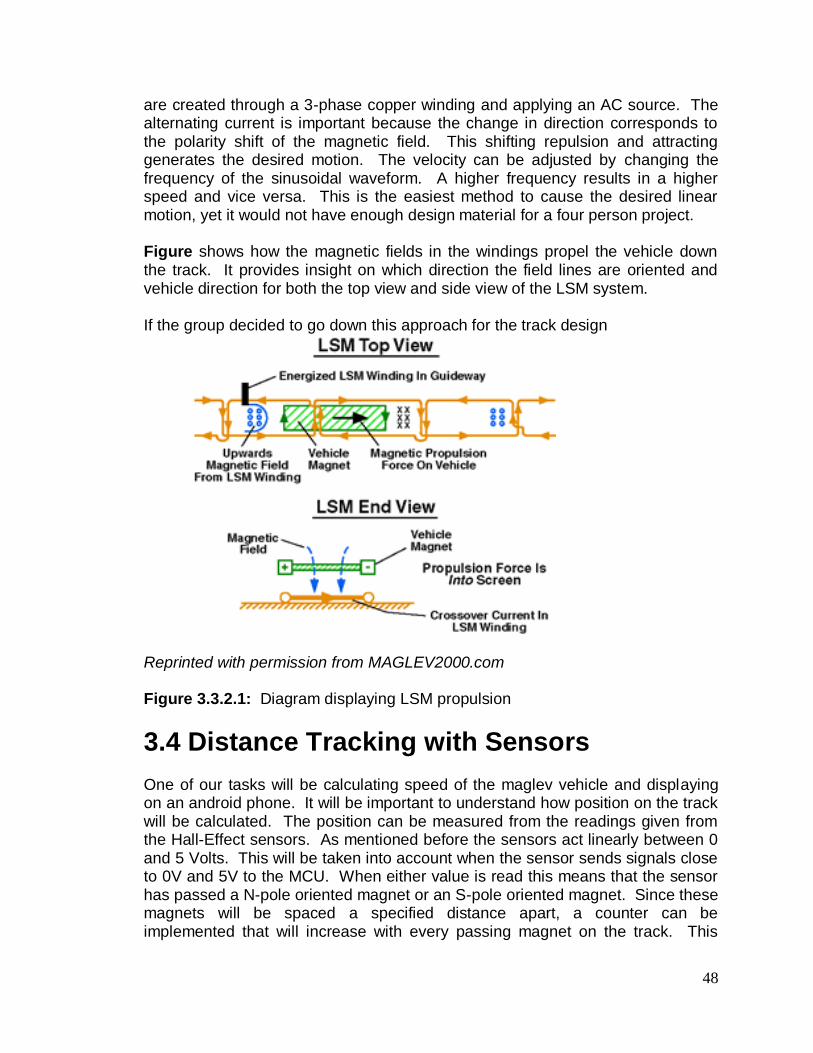
48
are created through a 3-phase copper winding and applying an AC source. The alternating current is important because the change in direction corresponds to the polarity shift of the magnetic field. This shifting repulsion and attracting generates the desired motion. The velocity can be adjusted by changing the frequency of the sinusoidal waveform. A higher frequency results in a higher speed and vice versa. This is the easiest method to cause the desired linear motion, yet it would not have enough design material for a four person project. Figure shows how the magnetic fields in the windings propel the vehicle down the track. It provides insight on which direction the field lines are oriented and vehicle direction for both the top view and side view of the LSM system. If the group decided to go down this approach for the track design
Reprinted with permission from MAGLEV2000.com Figure 3.3.2.1: Diagram displaying LSM propulsion
3.4 Distance Tracking with Sensors One of our tasks will be calculating speed of the maglev vehicle and displaying on an android phone. It will be important to understand how position on the track will be calculated. The position can be measured from the readings given from the Hall-Effect sensors. As mentioned before the sensors act linearly between 0 and 5 Volts. This will be taken into account when the sensor sends signals close to 0V and 5V to the MCU. When either value is read this means that the sensor has passed a N-pole oriented magnet or an S-pole oriented magnet. Since these magnets will be spaced a specified distance apart, a counter can be implemented that will increase with every passing magnet on the track. This

49
counter also has a specified distance associated with it. For example when the car goes too one N-pole magnet to the next S-pole magnet it has traveled the length of one magnet and the spacer in between. This distance will be roughly 1 inch. If each of the two straight sections of the track is roughly 2 feet, and the arcs are each 1 foot in diameter. The distance traveled around the arc is related to the circumference 2*(pi)*r. The radius is half a foot therefore traveling one arc length is equivalent to Pi feet or, 3.14592654 feet.
Track type (quantity) Length
Straight Section (2) 4ft
Half-circle (2) 6.283185307 ft
Total: 10.283185307 ft
One lap is equivalent of 10.28318 ft. Since there are about 12 magnets in relation to 1 foot the amount of magnets passed would be around 124 in total. Both sides of the propulsion gap have this amount of magnets so this equates to an estimate of 248 alternating polarity magnets. For distance measuring purposes only half of that number will be used. Figure 3.4 shows the distance between magnets and relative distance of the Hall-Effect sensors on the vehicle. The polarity of the magnets will alternate on the track for optimal drive. The spacers between the magnets are utilized for optimal magnetic field lines and also to cut down on costs since N42 magnets are expensive in large quantities. Now that the distance has been calculated it can be sent back to the android phone for speed calculations. The app itself will have an internal timer which will be set and reset with each trial run. Having a time measurement and distance reading, speed can be calculated and converted to desired units of measure within the coding of the app.

50
Figure 3.4: Interaction between sensors and track magnets
3.5 Three - Phase Drive System The sensors will be oriented on the car to send a three-phase voltage signal back to the MCU. This means that each linear voltage waveform for the sensors will be 120 degrees apart from one another as shown in Figure 3.5. The phases for each of the waveforms in Figure 3.5 correspond to the three Hall-effect sensors. The scale that is shown will also be adjusted having the 0 point be 2.5V ranging from 0V to 5V on the Y-axis. This is another reason why linear hall-effect sensors are important for the team’s drive system. Having a three-phase linear voltage reading allows for precise speed control by timed shut off and turn on of each one of the solenoids, along with alternating the polarity of the solenoids to the correct polarity of the upcoming track magnet. Each one of the solenoids will operate as such in the following cases, highlighted for the N-pole magnets but will work similarly to when interacting with an S-pole magnet.
3.5.1 Approaching N-Pole (-B) magnet When approaching an N-Pole magnet which gives a negative value magnetic field the sensors will output a decreasing voltage from 2.5V – 0V. Within these voltage ranges the solenoid connected to that sensor will have an S-N orientation, until the value is close to 0V.

51
3.5.2 Perpendicular to N-Pole (-B) magnet Once the output voltage from the sensor is near 0V, the respective solenoid will be turned off. This threshold voltage that needs to be crossed will have to be determined by trial and error. The best range for this voltage will be noticeable because the motion of the car will be smooth instead of erratic.
3.5.3 Leaving N-Pole (-B) magnet Once the threshold Voltage is passed again the solenoid will turn back on and have an N-S orientation pushing off the N-pole magnet. The N-pole magnet will push away the solenoid until it is attracted by the next S-pole magnet.
Figure 3.5: Three-Phase sinusoidal wave diagram

52
3.5.4 Test Case Scenarios for the Drive System This section is devoted to analyzing a number of cases for the three solenoid’s operations. Each case will be a hypothetical snapshot in time, and will show ideal cases for the current state of solenoid operation. The three states are OFF, N-S, and S-N orientation. The table in figure highlights six of the cases that will occur as the vehicle is propelled down the track. At any point in time there will be two sensors reading above the quiescent voltage of 2.5V, and one sensor reading below, or vice versa (two below 2.5V and one above). The only exception would be when one of the solenoids detects no field and the other two are above and below 2.5V respectively. These test cases cover 360 degrees of operation at the 6 points where one of the solenoids is off.
4.1 Initial Design Architecture
This section deals with all of the specific details regarding all of the hardware and software of the project. The hardware of the project consists of the track, the vehicle, the solenoid propulsion design on the vehicle, the MCU apparatus, the power mechanism and the Bluetooth connectivity hardware. The software is all of the code related to the project.
4.1.1 Track design The track is a large and significant portion of this project. It houses the necessary components that give life to a maglev vehicle. This section will discuss the initial design ideas and procedures that went in to the track. The first track design ideas were taken from the existing maglev train systems in use today: Electromagnetic suspension (EMS), Electrodynamic suspension (EDS), and Inductrack. Each track system has a different type of suspension/levitation system that was discussed in the introductory sections. Initial track design – Electromagnetic Suspension The EMS track design was our first design proposal for the track. The EMS track uses electromagnets built into the train/vehicle while the track is fitted with either conductive material or magnets. Our EMS design took a slightly different approach to creating the necessary propulsion. Instead of fitting the vehicle with electromagnets, we designed the track to have electromagnets on the sides while the vehicle was fitted with permanent magnets. These electromagnets would be interfaced with optical sensors that would be able to detect the presence of the vehicle when it was approaching. This way, the next electromagnet would turn on while the previous electromagnet would turn off.

53
This design was based off of an older senior design project, where the group created a maglev vehicle that used optical sensors with electromagnets. While this design looked great on paper, it had its flaws.
Manual labor intensive
Cost
Additional components
Unsure if the design met what the group wanted to achieve
This design is very labor intensive. It was decided that the amount of manual labor overshadowed the amount of engineering design that was desired to experience. The cost of the track would be very high, as this system was also analog. Another decision that was needed to be made was if a control system was necessary to keep the vehicle afloat or if permanent magnets would suffice. Most EMS systems make use of a feedback control system to keep the vehicle stabilized vertically and horizontally by monitoring the current in the electromagnets. After taking into account the manual labor, cost, and the availability of the parts that were desired, it was decided that this track design, while good, is not the best for what was desired. The next track idea was to follow the EDS system. Initial track design – Electrodynamic suspension The EDS system is in use in Japan as an experimental track to test the capabilities of the maglev train systems. The EDS system uses an array of superconducting magnets on the track and on the train to create lift and propulsion. The track and train both emit a very powerful magnetic field due to the caliber of magnets used. As explained in the introductory sections, it uses the push-pull effects of alternating magnetic poles to create propulsion. These push-pull forces can yield speeds that exceed 500 km/h (the land speed record for a rail vehicle was set by the JR-Maglev in Japan at 581 km/h. This rail is an EDS system rail). Our design would have followed suit with the existing EDS rails with permanent magnets fastened to the car and to the rail. However, there were obvious limitations to what we could do following an EDS design which led to removing the design completely. The EDS system had a multitude of problems that the group faced when deciding if this track design was the proper design for the project.
Type of magnets
Cost
Potential health hazards
Industrial hazards
Speed hazards
General non-feasibility

54
The EDS system uses super-cooled magnets that essentially create superconductors. An obvious problem with creating an EDS track is the cost. The magnets are cooled with a mixture of liquid nitrogen and helium to create the superconductor. The cost alone was enough to put this track design in the realm of non-feasibility but the limitations did not stop there. The magnetic fields created by the EDS systems are so strong that it creates health hazards for certain people. People with pacemakers are affected by the magnetic field, creating the need for magnetic shielding. Also, cellphones, credit cards, magnetic strips, et cetera, would also be compromised by the magnetic field. Finally, assuming that cost and health hazards were not issues, the speeds that an EDS rail system can achieve are ridiculously fast. So fast, that in terms of a senior design project is dangerous and not feasibly by any means. While EDS tracks are technologically sophisticated and capable of extraordinary feats, this track design was not feasible for what our project called for. Initial track design – Inductrack
The final track design idea was based off of the Inductrack rail system. As explained in the introductory section, the Inductrack is a passive rail system that uses unpowered loops of coil for the main track while the vehicle is fitted with permanent magnets arranged into a Halbach array. The interaction between the magnets on the vehicle and the track creates levitation. The group deviated from the typical Inductrack design which calls for passive coils and instead used permanent magnets. This track design is a mix of the EDS system and Inductrack design. This design consisted of a track that was fitted with both permanent magnets on the top of the track, and on the sides. Both magnet arrays would be arranged in a Halbach array in order to direct the magnetic field towards the car at all times. Another difference is that with this track, the vehicle would be fitted with a 3 phase motor system consisting of copper solenoids. The solenoids would interact with the magnets alternating poles to create the propulsion needed. No control system is needed as the vehicle is levitating at all times and there is no need for any type of magnetic shielding as these permanent magnets are not super cooled and thus do not create such an immense magnetic field. This design is not without its flaws either.
Cost
Labor intensive
Types of magnets
Dimensions of the track
Again, cost becomes an issue with the permanent magnets. Since both sides of the top of the track and both sides of the sides of the track must be lined with permanent magnets, the cost of just those magnets alone will be quite high. The magnets must also be oriented correctly to produce the proper levitation and propulsion that the project demands, which increases the amount of manual

55
labor for the project. The dimensions of the track are also under more scrutiny as the dimensions need to be able to accommodate the magnets and hold them adequately. Too much space will space out the magnetic field while too little space could convolute the magnetic fields. With these track designs in mind, the group decided to go with the Inductrack/EDS hybrid. This design was the most feasible in terms of achieving what was desired out of the project and had the least amount of setbacks. Cost will always be an issue but for the hybrid design, it is not a big enough issue to break the design outright. Design procedure – Track structure
With the basis for design chosen, the group then started the debate on what kind of track structure would be ideal to showcase maglev technology. There were a few factors to consider when choosing a structure.
A structure that would facilitate high speeds
A structure that would not inhibit vehicle movement.
With this criterion, the group turned to the current maglev rails in operation today for ideas on proper track design. Upon investigating the rails, the main difference between the maglev rails and the wheel-axle rails is the type of propulsion used. In essence, the rails are the same in terms of the type of structure and shape. With modern railway systems as reference, the group set out to decide if the track was to be a straight track, or a circular track. There were advantages and disadvantages with both track designs. Straight track advantages:
Simple construction
Showcases linear motion both forward and backwards. Straight track disadvantages:
A finite track
Can only showcase high speed provided the track is long enough.
A long track is cumbersome to transport.

56
Figure 4.1 – Rough sketch of straight track, initial design. Top view shown with segmented areas to show permanent magnet location. These magnets would provide the necessary levitation needed for the vehicle.
Circular track advantages:
“Infinite” track length.
Can showcase high speed maglev capabilities without restrictions.
A more compact design allows for easier transportation.
Circular track disadvantages:
Circular design will prove challenging to construct
Levitation and propulsion arrays will prove problematic when fitting to the track.

57
Figure 4.2 – Initial circular track design. Shown is a top view of the track with segmented areas to show permanent magnet configuration which provides the levitation needed for the vehicle.
Taking all of the advantages and disadvantages of the straight track design and the circular track design into consideration, the group decided to combine the two designs into a track resembling a NASCAR track. The final track design would be consisted of two straightaways and two curved areas. The group felt that the amalgamation of the straight track and circular track would be the most ideal due to the advantages of both of the tracks. Both tracks had ideal advantages that would allow for adequate demonstration of the maglev vehicle. While the circular track had the better demonstration capabilities, the straight track provided the ease of construction and would allow for viewers for better observation. With the NASCAR-like track, the maglev vehicle can demonstrate its high speed capability on an “infinite” track while showcasing the linear motion on the straightaways. The difficulty of construction is limited to the curved corners of the track, and transporting the track is made simple due to its curved shape.

58
Figure 4.3 – The rough sketch of the track design that was ultimately decided upon. Shown is the top view with the segmented rows to indicate the permanent magnet levitation arrays. The large arrows in the track show the direction of motion that will be demonstrated when the vehicle is in operation. The nature of the track allows for constant motion as it is an “infinite” track. The vehicle will be able to travel both forward and backward to showcase the entire range of linear motion.
The dimensions of the finalized track are as follows:
Straightaways: 2ft
Arc sections: 1ft diameter
Angle of curvature for arc length: ~90°
A 2-foot long straightaway is sufficient length to showcase the high speed capabilities of the vehicle. The arc lengths were designed to be a little longer to facilitate an easy transition to the adjacent straightaway. This way, the speed can remain constant while the vehicle travels from the initial straightaway, through the arc, and into the next straightaway. The arc segments were designed to have a curvature of 90°. This was done to demonstrate the level of control the vehicle can maintain while traveling at high speeds due to the nature of the propulsion.

59
Figure 4.4 – The arc dimensions shown. The diameter of each arc is 1ft while the angle of curvature is 90°.
Figure 4.5 – Straightaway dimensions shown. Shown is the corridor width, overall track width, and straightaway length.
The total distance of the track is as follows:
Total straightaway distance: 4ft
Arc section distance: 2 * pi * r = 3.141592654 ft
Total arc distance = 6.283183507 ft
Total track distance = 10.283183507 ft

60
Design procedure – Track material
Now that the design of the track was settled upon, the construction of the track was the next order of operation. The main issue was to find out what kind of material the track was to be constructed out of. This material would have to be:
Sturdy
Lightweight
Cheap
Unable to interfere with magnetic field.
Track material - Wood
The first material choice for the track material that the group decided upon was wood. Wood is an obvious choice as it fits the criteria of what the group wanted for a track for the maglev vehicle. The advantages and disadvantages of wood (generally speaking) are as follows: Advantages of wood:
Non-conductive
Easy to work with
Sturdy
Relatively cheap depending on the type of wood
Disadvantages of wood:
Weight
Cost depending on type of wood
Susceptibility to outside elements
The advantages of wood towards this project are obvious. The material is first and foremost non-conductive. Wood is also a sturdy material, able to facilitate the high speed travel relative to this project. The main problems faced with the debate of wood were the susceptibility to outside elements and the cost of wood. The bulk of the finance in the project is geared towards the permanent magnets, and as a result, cuts must be made in other departments. In order to construct a desirable track out of wood, the group was forced to investigate the different types of wood that would be considered worthy of constructing a track from. The types of wood considered by the group were:
Balsa
Oak
Pine
Cedar
Fir

61
The type of wood that was to be used was a source of debate within the group. Balsa wood is the lightest out of all of the considered woods; however it is flimsy and weak. For the track, the group decided that balsa wood is not ideal and would not be able to handle construction, let alone any of the propulsion forces. Oak was the next choice for debate amongst the group. The strengths of oak wood lie in its durability. It is strong enough to support the weight of the magnets and the forces acting on it via the vehicle’s motion. However, oak is heavy and somewhat expensive. As it was decided that much of the funding that the group was going to have to come up with would be put towards the magnets, the track material would have to be cheap and thus, oak was not chosen as the track material. The group next decided to investigate pine, cedar, and fir wood. While these materials were ideal in terms of constructing a stable and sturdy track, their expense was more than what the group would have hoped for. Track Material – Acrylic/Polycarbonate Wood proved itself to be reliable and sturdy; the drawbacks relating to the on average cost of wood and the techniques used to shape and fabricate the appropriate track would seem time consuming. Thus, the group’s next material to consider was acrylic and polycarbonate. These materials interested the group for their advantages including:
Non conductivity
Lightweight
Durable
Weatherproof
Acrylic and polycarbonate are ideal materials for creating a track. They are non-conductive, so they will not interfere with the magnetic fields produced by the magnets. They are lightweight, which helps with transportation and ease of use. Acrylic and polycarbonate are notorious for their durability. They are so durable that certain types are used in bullet-shielding. This project is not in serious demand of a heavy-duty acrylic polymer, but a sturdy, lightweight track is what is desired. Finally, an added bonus that acrylic brings to the table is that it is essentially weather proof. On its own, it does not fall subject to the elements, unlike wood. Wood is extremely susceptible to water which could potentially cause catastrophic damage to the track and any surrounding electronic equipment. With acrylic, the material itself is weatherproof. This way, any exposed corners and edges can be sealed off to create a weatherproof seal for the components housed inside the track. While acrylic and polycarbonate offer substantial benefits in the realm of creating a sturdy, lightweight track, the team discovered crippling disadvantages to creating an entire track out of these materials: The disadvantages of acrylic and polycarbonate:

62
Cost
Ease of fabrication
Handling (fabrication)
The main detractor from using either of these materials is the cost. Acrylic and polycarbonate sheets are quite expensive for the amount you get. Fabricating structures with acrylic and polycarbonate can be somewhat problematic as well. If using the wrong tools, the materials can split and crack in unwanted areas, and could potentially compromise the rest of the structure. While building a track made from entirely acrylic and/or polycarbonate is not in the realm of feasibility, the utility that these materials offer more than makes up for the disadvantages. For the propulsion magnets (which will be discussed in detail in the Track Dynamics section), it was decided that polycarbonate was to be used to house the Halbach array. Track Material – Wood substitute/Fiberboard The group decided that while wood itself would be too risky to commit the entire track to, a substitute that shared the as many advantages with it would be something to consider. With that, the group decided to investigate fiberboard and its advantages and disadvantages: Advantages:
Like wood, non-conductive
Inexpensive
Lighter than ordinary wood
Disadvantages:
Less sturdy than ordinary wood
Susceptible to elements
The advantages of wood are improved upon with fiberboard in the areas of cost and weight. Fiberboard is extremely inexpensive, much less expensive than ordinary wood. This offers the opportunity to let our budget breathe when it comes to the track materials. It shares non-conductivity with wood as well which makes it an ideal choice for the track. Finally, fiberboard is much lighter than wood. While acrylic is lighter than both fiberboard and ordinary wood, transporting fiberboard would be easy. The disadvantages of fiberboard while apparent are few. Structurally, fiberboard is less sound than ordinary wood due to it being a composite of wood particles. Its less dense and cannot handle the same type of stress that wood can. That being said, the type of stress that will be subjected on the track is not nearly severe enough to cause significant structural damage.

63
With all of the materials investigated and taken into consideration, it was decided that the track was to be constructed out of a combination of fiberboard and acrylic. These two materials were determined to be the best choices for a track based on reliability and cost effectiveness.
4.1.2 Track Design: Propulsion and Levitation The main purpose of the track is to facilitate a propulsion and levitation component that works in unison with the vehicle. The static propulsion and levitation components will be constructed out of permanent, neodymium-iron-boron magnets (NeFeB). The neodymium magnets will be arranged in a Halbach array to provide an adequate magnetic field that the vehicle will be able to take advantage of and thus lift and propel itself along the track.
Figure 4.5 – Magnetic field of a rectangular magnet 1” x .25” x .125” of grade N42. Reprinted with permission from K&J Magnetics, INC
Levitation – Halbach array theory
To achieve adequate levitation, a Halbach array is designed to create a localized magnetic field, where most of its strength is concentrated in one direction. The

64
group chose a Halbach array as it has demonstrated its usefulness in achieving a desired magnetic field. The advantages of a Halbach array:
Minimizing friction and drag
Low magnetic field (for commercial sized trains, this is ideal as passengers would not be exposed to high magnetic fields. To certain individuals, high magnetic fields can be lethal).
Reduced power consumption.
Figure 4.6 – Magnetic calculator showing repelling force between two magnets, 1” x .25” x .125” of grade N42 at a distance of 0.20”. Also shown is the strength of the magnetic field in Gauss and the Permeance Coefficient. Reprinted with permission from K&J Magnetics, INC.
Since the levitation through a halbach array means the vehicle would not be touching the track, this means that friction between the vehicle and the track would be non-existent. In terms of drag, a halbach array can reduce the drag from the eddy current. As the magnets pass through the magnetic fields at a faster rate, the drag from the eddy current increases. Halbach arrays are of a low magnetic field. Since they are not electromagnets, the potential dangers of using electromagnetic levitation are non-existent. Finally, the nature of the halbach array dictates that it is low power. Traditional halbach arrays in use today make use of passive coils. The projected described in this paper makes use of permanent magnets. In either case, there is miniscule power consumption by the halbach arrays. The main type of Halbach array system in use today is the Inductrack system. The Inductrack halbach array makes use of permanent magnets that pass over

65
unpowered loops of wire called Litz wires. The Litz wires are made of up smaller wire strands that are woven in distinct patters to carry AC current. The halbach array passes over these magnets and thus, levitation is achieved.
Figure 4.7 – Rough sketch of the passive coils used in the Inductrack rail system. This is a 3-phase winding.
In order to get the vehicle to levitate on its own, it needed to be subject to a magnetic field of the same polarity as the magnets equipped on the vehicle. However, since there are two arrays of magnets that are attached to the track (the levitation array and the propulsion array), it is necessary to minimize the flux in all other directions besides upwards. If the magnetic field from the levitation array were to cross the magnetic field from the propulsion array, there would be interference which could compromise the entire vehicle. In the event of interference, the flux would be distorted by the surrounding magnets that are located in the propulsion array and possible the other magnets that are located in the levitation array. This distortion could possibly:
Negatively affect the levitation on the car
Adverse effects relating to the propulsion
These types of adverse reactions can have unforeseen complications during building and testing of the track, vehicle, and the tendency of motion relating to the vehicle as it passes through the magnetic flux of the propulsion arrays. Also, the tendency of levitation can come under scrutiny if these adverse reactions were allowed to take place. Shown in the figure below is an example of a Halbach array that showcases the tendency of the magnetic flux.

66
Figure 4.8 – A halbach array using neodymium magnets. The orientation of the magnets effectively nullifies the flux on the bottom side while the flux on the top side is reinforced and directed. The flux on the bottom can never truly be reduced to zero. As noted in the picture, a magnetic flux exists, albeit weak. Reprinted with permission under the Creative Commons CC0 1.0 Universal Public Domain Dedication.
To avoid this, the magnets are arranged so that the flux above the magnets is reinforced and directed, while the flux below the magnets is nullified as close to zero as physically possible. This is the fundamental of the Halbach array. By localizing and reinforcing the flux upwards, the field is directed towards the undercarriage of the car. The flux on the magnets on the car would be directed downwards, by equipping the undercarriage of the car with magnets that are magnetized through the thickness of the magnet. Now that the both the vehicle’s flux and the track’s flux are directed towards each other, and the magnets in use are of the same polarity, both objects will repel each other. This repulsion creates the levitation needed for the vehicle to work successfully. The picture below details, roughly, how the magnets would be oriented on the vehicle and on the track.

67
Figure 4.9 – The cutout view of a prototype track design detailing the levitation magnets and the vehicle permanent magnets. The arrows dictate the direction of the flux. The repulsion from the like-poled magnets would create a strong enough levitation to keep the vehicle situated above the track.
Propulsion – Halbach array theory The same theory that went into developing the levitation array went into the propulsion array as well. The threat of interference from magnets used in the sides of the track was too large to not employ a Halbach array. A halbach array for the propulsion proved to be a little more challenging than the array for the levitation. The propulsion is oriented towards the center of the track. This means that the array must be rotated so that the magnetic field is pointing towards the slot that the linear motor sits in. However, this array is identical to the array on the opposite side of the track. The magnetic field lines from both arrays, will cross over the solenoid as it passes through.

68
Figure 5.0 – The side-view cutout of the track featuring the propulsion magnets. The field lines shown are the result of the halbach arrays on either side of the track. Ideally, the field lines are to be focused on the solenoid and should be minimized as to not interfere with the levitation array.
A design idea for the halbach array pertaining to the propulsion magnets was taken from the FTC Robotics team, Antipodes. The team used an alternating magnet/spacer combination for the propulsion array that consisted of rectangular neodymium magnets separated by brass spacers. Behind these brass spacers however, were cylindrical magnets oriented in a halbach array. This design is interesting as it provides a strong propulsion base with the permanent magnets, and offers a reinforced magnetic field from the spacer array.
Figure 5.1 – A mock representation of the Team Antipodes brass spacer configuration. The cylindrical magnets are arranged in a halbach array to where the flux is directed towards the solenoid, the center of the track.

69
Sample case #
Voltage Solenoid (1
being front and 3 being back)
State (Off, N-
S, or S-N)
1 3.75V 1 N-S
0V 2 OFF
3.75V 3 S-N
2 5V 1 OFF
1.25V 2 N-S
1.25V 3 S-N
3 3.75V 1 S-N
3.75V 2 N-S
0V 3 OFF
4 1.25V 1 S-N
5V 2 OFF
1.25V 3 N-S
5 0V 1 OFF
3.75V 2 S-N
3.75V 3 N-S
6 1.25V 1 N-S
1.25V 2 S-N
5V 3 OFF
4.1.2 Solenoid Design The car will have three solenoids mounted on the bottom of the car utilizing mounting brackets that will fit a ¼ inch to ½ inch tube preferably made of iron. Iron or steel tubing would be ideal, because the ferrous metal will strengthen the magnetic field the solenoids will produce. If not there are other options for small diameter tubing such as copper and brass, that could be ordered in a vast quantity of sizes from onlinemetals.com. For the purposes of this project each solenoid won’t exceed 2 inches in length, so buying tubing of around 6 – 8 inches will provide enough tubing to cut and make the cores of our solenoids. If mounting brackets are hard to come by with the right fitting for the tubing, purchasing a channel could be another plan. In this channel tubing holes can be cut out to insert each of our solenoids. The channels material should not interfere with the cars magnets or the tracks, so aluminum would be ideal. Two factors are important when creating the solenoids, the number of turns and the current driving through them. Since the current flowing through each solenoid will be 1 amp or less the solenoids must be wound a great deal. Utilizing a small gauge of wire (around 30 gauge) and providing a substantial

70
number of turns to cover the surface of the core multiple times, the solenoids can be built of substantial field strength to interact with the track magnets. Winding hundreds of feet of copper wire would take an incredible amount of time, so using the help of a drill would save the team valuable time in construction. It is very important that the turns of the solenoid be exceptionally tight otherwise the magnetic fields produced will not be of the desired intensity/orientation. The rough material and dimensions for solenoid creation is itemized below.
8’’ of ferrous metal tubing ¼’’ thick Inside Diameter
30 AWG copper magnet wire approximately 1000’ of length
Mounting brackets to vehicle or aluminum channel with cut outs
4.1.3 Car Design
4.1.3.1 Lego Design
The initial design idea was to build the car using an assortment of Lego bricks and stud plates. Seeing as Lego construction is extremely easy, it would eliminate the need for power tools when designing the dimensions of the car. Some of the Lego pieces that would be needed for this design path are listed as follows.
5’’ x 8’’ Lego stud plate foundation
(4) 4 x 1 stud Lego bricks
(2) 12 x 1 stud brick
(4) 4 x 8 stud brick
(3) 4 x 6 stud brick
(4) 1 x 10 stud brick With these bricks and maybe a few more depending on what is needed when building the car actually begins the base and foundation of the car will be built. Thought also needs to go into housing the two Neodymium magnets that will cause levitation above the track. Since no one in the group has access to a substantial amount of Legos, and buying individual Lego bricks per design could get expensive, we will not be building our car using Lego parts.
4.1.3.2 Wood Design The other option for building the car is just prototyping out of wood. The type of wood is up for consideration a few factors should be considered when purchasing the material.
Price
Hardness/durability

71
Ease of cutting We will have access to power tools, but the less labor required the more productive the team will ultimately be. The wood block that will be purchased has the following dimensions, which if not available can be cut with a table saw to scale down.
- 7’’ x 4’’ x .5’’ wood block For the car foundation hardwood would be ideal, because drilling and shaping needs to be done to glue the permanent magnets to the bottom of the wood block. Balsa wood is too soft for our purposes, but was considered. Pine will be used instead, and if it is not possible to obtain the correct dimensions we need two pieces can be cut and spliced together.
4.1.4 Car Prototype Diagrams
4.1.4.1 First Car Prototype The group’s first design idea included four magnets that would be located on four extended corners of our car. The four magnets would roughly be rectangular 1’’ long and ½’’ wide; this will fit ideally glued to the underside of the 1.5 inch appendages from the main body. The simplified breakdown of the material dimensions is as follows.
(2) 7’’ x 2’’ pine wood blocks
7’’ x 4’’ pine wood block
4’’ x 3’’ Circuit board housing
(4) 1’’ x ½’’ N42 NdFeB rectangular magnets
Figure 4.1.4.1: Top view of 1st car Prototype

72
4.1.4.2 Second Car Prototype The second prototype for our car used only one wood cross section instead of two like in the 1st prototype. Having only one section across the middle will affect levitation stability in a negative manner. To counteract this negative stability affect we will have to purchase larger magnets and orient them lengthwise across the middle piece. The team thinks that ultimately this design will not be the best candidate, because it will cause the car to rock/dip in the front and back when significant acceleration forces are applied when braking at specified distances. The simplified breakdown of the material dimensions for the second design is as follows.
7’’ x 4’’ pine wood blocks
7’’ x 4’’ pine wood block
4’’ x 3’’ Circuit board housing
2’’ x 1’’ N42 NdFeB rectangular magnets
Figure 4.1.4.2: Top view of 2nd car Prototype
4.1.5 Car Materials There are three major components for the car design.
Wood foundation
Aluminum channel

73
PCB/Microcontroller housing The aluminum channel houses the solenoids and the wiring to and from the Arduino/PCB located on top of the car. The housing for the PCB and microcontroller for aesthetic reasons will be comprised of Plexiglass. This will display the LED’s on top of the PCB more clearly to indicate electromagnet polarity. Non-ferrous screws are ideal for construction as to not interfere with the car or track magnets. A strong epoxy adhesive is needed for attaching the magnets to the underside of the car; otherwise safety could be a concern when adjacent magnets come within proximity of each other and fly into someone’s eyeballs.
4.1.6 Building Plan for First Prototype This step by step procedure gives a rough building plan for the 1st prototype the team designed for the car. By no means should this be considered a final and exact approach to the end product. This procedure also only details the car foundation for which will house the solenoids, circuitry, and PCB board/MCU/Bluetooth. 1. Cut wood blocks to specified dimensions if not already done. Make sure the
pieces of board are roughly ½’’ to ¾’’ wide.
2. Cut the two 7’’ x 2’’ wood pieces into four 3.5’’ x 2’’ sections, this is done to leave a space for the roughly 2’’ wide aluminum channel that is to be fit across the bottom of the body piece.
3. Since now the wood pieces exceed the desired dimensions cutting down to size so that the extensions from the main body are only 1.5’’ can be done.
4. Connect the four sections to the corners of the body piece by drilling non-ferrous screws. The screws should be small in length not more than ½’’ the width of the board. Wood glue could also be used, which might produce better results than the screws.
5. Next it’s time to attach the magnets to the four corners of the car. This needs to be done with an extreme adhesive, like a two-part epoxy It is important to keep other magnets away while the adhesive is drying. Some important tips for gluing Neodymium magnets were found from K & J Magnetics website. o Always clean the surface of the side of the magnet with Isopropyl alcohol.
The oils from fingerprints can be enough to lessen the bond to the gluing surface.

74
o Scratching the surface of the magnet to enhance the bond. Do this with sandpaper or a sharp object such as a nail.
o Many strong adhesives will work, but what works best is Two-part Epoxy. When buying Two-part epoxy there is a variety of drying times between 5 and 30 minutes. The quicker the drying time the better, although the price seems to reflect this time reduction.
o It is important not to use a glue gun; the high temperatures can demagnetize the magnets.
6. Once the main body is finished it is important to now focus on the design of
the aluminum channel. This channel will hold the three solenoids, circuit wiring and the Hall Effect sensors for position sensing. The channel will be between 1’’ and 2’’ wide and run the length of the board, about 7’’.
7. Cut three circular holes through both sides of the aluminum channel to house the solenoid tubing cores. Cut big enough to fit to size of the solenoid tubing, if oversized it should not be a problem if two rubber washers are placed on both ends of the solenoid pipe. Double check the spacing of these holes they should be far enough apart so that the sensors can be correctly placed in-between to detect the magnet polarity and position..
8. Next the ferrous pipe must be cut into three sections for each of the respective solenoids. These should be about 2’’ in length cuts for each solenoid. A handsaw for metal cutting will work but is a labor intensive process.
9. These pipe sections must then be made into spools by attaching aluminum or another type of cut out which should fit the tubing size and extend about ½’’ to an 1’’ above the outer diameter of the solenoid tube. Use more 2-part epoxy to secure.
10. The Solenoids must now be wound. This will be time consuming as to the fact that the team will be winding over a 1000 feet in total of copper. A winding drill should be utilized to lessen labor. Keeping the windings tight is important as well, every so often a bead of glue should be utilized to keep the winding close and intact.
11. Before the channel is attached to the underside of the car all the wiring for the Hall Effect sensors, solenoids and H-bridge drivers should be done and organized so that once the channel is screwed in place there will not be a need to take off again.

75
12. The housing for the MCU and PCB board will be created from leftover plexiglass after creation of the track. It will be roughly four inches tall, and be wide enough to fit the 3’’ x 2’’ Arduino board with the stackable Protoshield.
4.2 Microcontroller programming If we plan on completing our design we need to know what we will get out of having a microcontroller. As described earlier, we will need it to be taking analog inputs and use that information to send the correct signals out in order to control our vehicle. We will use the diagrams for port values that we have found along with schematics we’ve created to code our MCU in order to complete our tasks
4.2.1 Programming functions
4.2.1.1 Receiving order from Bluetooth
controller The first step for the MCU to function our car is simply to receive a signal. Our microcontroller will be controlling this system, but its directions will be received from a Bluetooth controller device. We expect that this will be something along the lines of a simple phone app that connects to the MCU wirelessly. It will not connect wireless directly because the Atmega328 does not have an on-board wireless device. The way we will connect the Atmega328 to the Bluetooth controller is through the RN-52. The RN-52 is a Bluetooth enabled, information medium for this specific purpose. So the code and wiring involved for the Atmega328 will be for the RN-52 device and not the controller directly. Figure 4.2.1.1 - Bluetooth Block diagram
D12,D1
3
(Digital
input)
Atmega328P Take input {
control_in0= digitalread(D12); }
RN-52 UARTTX UARTRX

76
Following the diagram above, we can see the UARTTX and the UARTRX ports of the RN-52 connected to the Atmega328 through the digital input ports of D12 and D13. Once the devices are connected properly, we will need a code to direct the Atmega328 to take an input. This code will follow the pattern of the code shown in the figure above. Digitalread (*port) will take a value being input from the device, and all we have to do is the value to a variable of our choice. The code will save the current input as a variable and begin testing. The device will be sending one of four signals; Brake, speed 1, speed 2, speed 3. Speed 1,2, and 3 will all lead to the same core function of moving the cart. The only thing that will be different is the speeds at which the magnets are changing causing the vehicle to move. If it receives a brake signal, it will cause the MCU to perform the functions it needs to in order to stop the vehicle. Once the controller takes the signal, it can begin functioning throughout the rest of the code.
4.2.1.2 Taking the Hall-effect Input
Figure 4.2.1.2 – Hall effect Block diagram
Once the MCU has received an order from the Bluetooth device, the next step is taking the Hall Effect input. Taking the Hall Effect input is the first step of the movement process of the Maglev vehicle. Without this step, our vehicle would be unable to determine where it is in relation to the magnets on the track and therefore wouldn’t be able to accurately move itself in the expected direction. Also, our car will be controlling the solenoid magnets based on whether the solenoid is next to a N or S polarized magnet. Using this information it will be able to determine the pattern it will change its own solenoids. In order to function the Atmega328 to receive the input from Allegro A1301 we will have to make sure the ports are established correctly. We will have three Hall Effect sensors connected to the analog ports of the Atmega328; A0, A1, and A2. We will have the input be saved as a variable whenever we need to read the
Allegro A1301
Atmega328P Take input {
alog_in0= Analogread(A0); }
VOUT
A0 – A2
(Analog
input)

77
sensor. The code our group will use will be variable= Analogread(*port). This means our MCU will take the signal being received by whichever port that is in the parenthesis and save it into the variable. Obviously for our actual programming we will have variables and ports correctly established for efficiency and organization. Once we have the current analog value saved into a variable of our choice we are free to use it however we choose.
4.2.1.3 Microcontroller Conversion function
Function {
If (Alog_in0=5) PassN0=0; PassS0=0; Delay 10ms; PassN0=1; PassS0=0;
If(Alog_in0=0) PassN0=0; PassS0=0; Delay 10ms; PassN0=0; PassS0=1;
If(PassN0) SW0=1; SW1=0;
Else If(PassS0) SW0=1; SW1=0;
Else SW0=0; SW1=0; } The functioning of the microcontroller is a crucial portion of the project. The MCUs job is take the input it received from the Hall Effect sensors and convert that information into digital outputs that will be in charge of controlling the solenoid magnet polarities. This means that it will take an analog value and turn it into digital outputs. The pattern it will follow is based on the three phase sinusoidal diagram Figure 3.4: Interaction between sensors and track magnets. If the analog input has just

78
passed the 5v mark it means that the specific sensor has just passed an S polarized magnet. If it has just passed an S polarized magnet the solenoid needs to be SN oriented. If it has just passed by the 0V marker it means that specific sensor has just passed through an N polarized magnet. If it has just passed through an N polarized magnet, it needs to be NS oriented. Now if it is reading exactly 5 or exactly 0 that means it is directly aligned with either a magnet of either polarization. When it is directly aligned with either polarized magnet the solenoid needs to be turned off. Following this specific pattern will allow each magnet to move cohesively and separately allowing for smooth motion in the direction of our choice. The way we accomplish the task of turning the analog input into a correctly oriented solenoid described above is the programming. The small portion of code above is just an example of what the code will be doing. The variables will be similar, but syntax and exact names and coding will differ once we grow closer to completing every goal. The code is also based on just one of the analog input ports; while the final code will be contain all the analog ports. The code shows an if statement that will determine if the analog signal being received is exactly 0V or exactly 5V, if this is the case, the switches will change to turn the solenoid off. Based on our understanding of the H bridge circuit, we will have to change switch 1 to 0 and switch 2 to 0 also. With both of these being 0, it will cause the circuit to put no current through the solenoid effectively turning it “off.” Another possibility is that the Hall Effect and solenoid has just passed 5V (South polarized magnet) this means it needs to be SN. The S side of the solenoid will push away from the S magnet behind it and attract itself to the N magnet in front of it. The way the solenoid is changed from off to SN is by changing the switches in the H-bridge circuit. The SW0 will be changed to 1 and the SW1 will to 0. Once it gets to the N magnet the Hall Effect sensor will read 0 and the MCU will use this information to determine it just passed the N magnet. After it is turned off briefly it will switch to NS. The N solenoid side will push away from the N and attract itself to the S magnet coming up. The way it switches to NS is by changing the SW0 to 0 and the SW1 to 0. The last possibility is if the MCU is receiving a “brake” command from the Bluetooth controller. This means that it will no longer be following the pattern for movement described above because we do not want any movement. The way our group has decided to handle this situation is by setting the value of switches and leaving them unchanged. This will effectively stop the Maglev vehicle by attracting itself to one spot of the track. This means that if the Hall Effect sensor is producing a 5 signaling an S magnet, the solenoid will be set to NS. This will pull the car to that point and stop. The same goes for if the signal was 0 signaling an N magnet. The solenoid would switch to SN and it would hold itself in position. If this process is completed correctly then the MCU will have an efficient braking system.
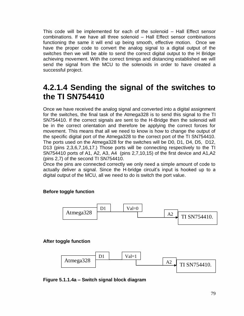
79
This code will be implemented for each of the solenoid – Hall Effect sensor combinations. If we have all three solenoid – Hall Effect sensor combinations functioning the same it will end up being smooth, effective motion. Once we have the proper code to convert the analog signal to a digital output of the switches then we will be able to send the correct digital output to the H Bridge achieving movement. With the correct timings and distancing established we will send the signal from the MCU to the solenoids in order to have created a successful project.
4.2.1.4 Sending the signal of the switches to the TI SN754410
Once we have received the analog signal and converted into a digital assignment for the switches, the final task of the Atmega328 is to send this signal to the TI SN754410. If the correct signals are sent to the H-Bridge then the solenoid will be in the correct orientation and therefore be applying the correct forces for movement. This means that all we need to know is how to change the output of the specific digital port of the Atmega328 to the correct port of the TI SN754410. The ports used on the Atmega328 for the switches will be D0, D1, D4, D5, D12, D13 (pins 2,3,6,7,16,17.) Those ports will be connecting respectively to the TI SN754410 ports of A1, A2, A3, A4 (pins 2,7,10,15) of the first device and A1,A2 (pins 2,7) of the second TI SN754410. Once the pins are connected correctly we only need a simple amount of code to actually deliver a signal. Since the H-bridge circuit’s input is hooked up to a digital output of the MCU, all we need to do is switch the port value. Before toggle function
After toggle function Figure 5.1.1.4a – Switch signal block diagram
A2 TI SN754410.
Atmega328 D1 Val=0
A2 TI SN754410.
Atmega328 D1 Val=1

80
Using something simple such as “Digital_Toggle(port),” which is a code that allows the easy switching of the digital output signal, we can accomplish this task. For example, if the output port D1 on the Atmega328 is set at 0, we can simply run the code of Digital_Toggle(D1) and we will see that the new value of that wire is 1, instead of 0.When the wire value switches, we can see that it also switches value in the TI SN754410. This means that it switch the flow of current if the switches are organized correctly. This change in current is what will be changing the polarity of solenoids and effectively moving our vehicle. There are many different possibilities for switch organizations that we will have to be aware of in order to get our car to function properly. As described early, we would need the magnet to be oriented to NS if the magnet it just passed is N polarized. We will need it to be SN if the magnet it just passed was S polarized. If the magnet is aligned with either an S or N polarized magnet we will need the solenoid to be turned off. Finally, if the command received from the Bluetooth controller is to brake, we will need the solenoids to be oriented to the magnet it is aligned with in order to hold itself to that specific part of the track. Just passed a N polarized magnet Below we have a diagram of switch signals whenever the MCU has determined it has just passed by an N magnet.

81
Figure 5.1.1.4b – NS magnet block diagram In the diagram we can see every feature of the magnetic pull that we intend to occur. It begins simply by toggling the output value on the MCU it will lead to the pull of the magnet. Since the solenoid just passed an N polarized magnet, we changed the switch values to match what they would need to be in order to create movement. The switches changed in the H-Bridge circuit allow the current
F
TI SN754410.
Val=1 (switch
value)
Val=0 (switch
value)
Atmega328
Current direction
Solenoid
F

82
to go through the solenoid in the intended fashion causing it to be N based on this side. Remember that since magnets are double sided, the solenoid will have a mirrored orientation on the opposite side. Just passed S polarized magnet Below we have the diagram of switch signals whenever the MCU has determined it has just passed by an S magnet. Figure 5.1.1.4c – SN magnet block diagram This step is similar to step previous, but instead we just passed an S polarized magnet, therefore we need the circuit to change so that the solenoid is S
TI SN754410.
Val=0 (switch
value)
Val=1 (switch
value)
Atmega328
Current direction
Solenoid
F F

83
polarized for the intended forces. We can see that simply by changing the values of the Atmega328 outputs we have changed the direction of the current and therefore changing the polarity of the magnet. This back and forth pattern will lead us to moving correctly along the track. When solenoid is aligned with a track magnet (either S or N)
Below we have a diagram showing the switch signal values when the solenoid is aligned with the track. Figure 5.1.1.4d – No magnet block diagram
N
o
M
a
g
n
e
t
TI SN754410.
Val=0 (switch
value)
Val=0 (switch
value)
Atmega328
No Current
Solenoid

84
The figure above shows the switch orientation whenever the magnet is aligned with a track magnet. Since there is no perfect way to pull or push in the “correct” direction when directly aligned, we need to turn off the magnet and let the other magnets do the work during this phase. Since we will have each solenoid functioning along with each combination, the aligned magnets will not have to be creating any force and the other solenoids will be able to move successfully. Brake signal Below we have a diagram of the switch signals when the MCU has received a signal to stop the system. Figure 5.1.1.4e – Aligned Magnet block diagram
TI SN754410.
Val=0 (switch
value)
Val=1 (switch
value)
Atmega328
Current direction
Solenoid

85
Whenever we receive a signal of “brake” from the Bluetooth controller we need to
set the solenoids polarity to whichever magnet is closest to it. For example,
above we have received the “brake” command and our magnet is aligned with an
N magnet. This means that we will change the H-Bridge circuit’s switches to
cause the solenoid to be S polarized so that they will pull towards each other.
Since they are pulling towards each other in the diagram above, we will witness
the maglev vehicle stopping.
Figure 5.1.1.4f – double sided diagram
With each of these switch organizations, only one side of the Solenoid and track
were shown. As we know all magnets are oriented NS or SN which means the
other side of the track needed to be shown. The figure above shows the top view
of the solenoid to track relationship. We can see the dotted line separating what
was shown and what was not. The magnet in the middle is the solenoid which is
two sided. Since the opposite sides of the track have opposite polarities, the
forces remain pushing the cart in the same direction.
4.2.1.5 Bidirectional vehicle
One of the signals that can be sent from the Bluetooth controller is to drive the
opposite direction. This means that the same process will happen, just in
reverse. All of the measurements will occur in the exact same way, but the timing
on when the solenoid is changing will change. If we simply run the system in
reverse and account for distance calibrations, we should be successfully able to
move our car backward.
If anything changes, it will be the programming code that is running. The
connections and signals will still function exactly as they did before; the only

86
difference will be the MCU’s programing to change the switches. Instead of being
SN when it there is an S polarized magnet behind and N in front, It will be NS, in
order for the forces to move it backwards. If the switches are being sent out
correctly, then the car will move correctly also.
4.4 Android Application Development Architecture The interface through which the user will control the system is directly through the remote control which has been established to be an android smartphone. There are many examples of applications of reference that do a similar task as the group’s intended function for developing an android application, which is communicating with an external device through Bluetooth communication. For this specific project, a specific application with a specific task is needed. In order to access the Bluetooth libraries from Android Plugin, permission must be granted in the manifest file of the root directory. The manifest brings the important information about the application to the Android system. This information is necessary before the system can execute any of the code. Some important aspects of the manifest file are as follows:
It possesses the Java package which serves as an identifier for the application
Used to describe all of the components including services, activities, broadcast receives, etc.
Declares which permissions the application has to have for it to access guarded sections of the programming interface and comingling with other applications
It also lists other’s permission needs to interact with this application’s components
Declares the minimum level of Android application programming interface that this application needs
It also lists the necessary linked libraries that are accessed by the application
What the group’s application is interested in, is the permissions part of the manifest file since it will be accessing an external library and needs to interact with the smartphone’s built in Bluetooth application. The permission is declared in the manifest file as follows:
<manifest … >
<uses-permission android:name=”android.permission.BLUETOOTH” />
…

87
</manifest>
4.4.1 Application Class Diagram Figure 4.4.1 shows the class diagram for the overall application. The method used for the diagram is considering that the application will be developed using a standard version (ver. 4.3) of the Eclipse Integrated development environment with the Android development tools plugin. Each class and or activity shows the objects and functions that are essential to its specific purpose.
Class Diagram – Maglev Controller
Figure 4.4.1
4.4.2 Application Programming Plan

88
Main Class The Main class is where the connection will be established between the android smartphone and the microcontroller (through the Bluetooth module). Below is the definition of the main objects and methods and examples of how they will be coded in the Android application.
- BluetoothAdapter object: Allows the application to interact with the Bluetooth software already present in the smartphone. This then allows the user to enable Bluetooth directly through the application.
BluetoothAdapter BtAdapter = BluetoothAdapter.getDefaultAdapter();
If (BtAdapter == null) {
// Bluetooth is not supported by device }
If (!BtAdapter.isEnabled()) {
Intent enableBtIntent = new
Intent(BluetoothAdapter.ACTION_REQUEST_ENABLE);
startActivityForResult(enableBTIntent, REQUEST_ENABLE_BT);
}
- Devices Set: Will keep track of the paired devices with the smartphone. In
this application, the user is only interested in the specific micro controlling system for the magnetic levitation vehicle.
Set<BluetoothDevice> Devices = BTAdapter.getBondedDevices();
// If any paired devices
if(Devices.size() > 0) {
// loop through the paired devices
for (BluetoothDevice d : Devices){
// Add name and address to array
mArrayAdapter.add(d.getName() + “\n” + device.getAddress());
} }
- BroadcastReceiver object: Once the device begins to discover new
devices in range, it is necessary to gather information about each device. The user wants to make sure that it is establishing connection with the correct device, as there may be other devices in range during testing such as other smartphones, so information about the devices is important.
- OnReceive method: Will allow the user to decide what happens when the
information is received.
Private final BroadcastReceiver mReceiver = new BroadcastReceiver(){
public void onReceive(Context context, Intent intent) {
String action = intent.getAction();
// When discovery finds a device
if (BluetoothDevice.ACTION_FOUND.equals(action)) {
// Get the BluetoothDevice object from the Intent
BluetoothDevice device =
intent.getParcelableExtra(BluetoothDevice.EXTRA_DEVICE);
// Add name and address to an array adapter to show in a ListView

89
mArrayAdapter.add(device.getName() + "\n" + device.getAddress());
}}};
- IntentFilter object: This is needed to register the broadcast receiver.
// Register the BroadcastReceiver
IntentFilter filter = newIntentFilter(BluetoothDevice.ACTION_FOUND);
Controller Class
The Controller class will be the main activity and interface through which the user will interact wirelessly and control the magnetic levitation vehicle. Through this activity as it is called by the Integrated Development Environment, the user will be able to send commands and receive information about the vehicle. All of these commands and information will be handled by the system or the vehicle’s microcontroller.
- Forward: This is a constant of type integer which will represent the command to move the vehicle in the forward direction
- Back: This is a constant of type integer which will represent the command to move the vehicle in the backwards direction
- Stop: This is a constant of type integer which will represent the command to brake or stop the vehicle when it is moving in either direction
- Distance: This is a variable of type integer that will be measured in centimeters
- moveFoward method: This method will handle the command sent to the vehicle to move it in the forward direction. It will send the Forward constant of 1 through 3 that will be received by the microcontroller
- moveBack method: This method will handle the command sent to the vehicle to move it in the backwards direction. It will send the Back constant of 4 to 6 that will be received by the microcontroller
- stopVehicle method: This method will handle the command sent to the vehicle to stop its motion in either direction. It will send the Stop constant of 0 that will be received by the microcontroller
- getDistance method: This method will continuously query the server to update the distance traveled by the vehicle during any point in time and will be called and return to the displaySpeed method.

90
- dispalySpeed method: This method will handle the speed calculation of the vehicle and will be updated continuously during the vehicles path about the track
ConnectThread Class The Connect Thread Class is a thread that will allow both devices to establish a connection and begin exchanging information. In order for this connection to be made, a server and client must be established where one device opens a server socket and the other device initiates the connection by using specific information about the other device. So the server will hold the Bluetooth socket open and listen for a request from the client, and accept the request upon getting the connection request. In this formation, the ConnectThread class serves or behaves as the client.
- InStream: Handles the information coming in through the socket
- OutStream: Handle the broadcasting going out of the socket
- ConnectThread construct: Declares the socket and streams for the connection through which data will be transmitted
public ConnectedThread(BluetoothSocket socket) {
mmSocket = socket;
InputStream tmpIn = null;
OutputStream tmpOut = null;
// Get the input and output streams, using temp objects because
// member streams are final
try {
tmpIn = socket.getInputStream();
tmpOut = socket.getOutputStream();
} catch (IOException e) { }
mmInStream = tmpIn;
mmOutStream = tmpOut;
}
- Write (byte) method: sends data through this socket. Along write is also a Get (byte) method that gets the information coming through the server socket. This is where the commands will be sent to the vehicle and data or information on the vehicles location on the track will be received.
// Called from the main activity to send data to the remote device
public void write(byte[] bytes) {
try {
mmOutStream.write(bytes);
} catch (IOException e) { }

91
}
- Cancel method: Is used to end the connection between the paired devices. This method can be called from the main class or thread when device pairing is done
// Called from the main activity to shutdown the connection
public void cancel() {
try {
mmSocket.close();
} catch (IOException e) { }
}
As mentioned, one of the devices must act as a server and the other as the client in order for one to open the connection and the other device to make the connection. Figure 4.4.1.1 shows the ConnectThread Class and the AcceptThread class in the Client-Server model system. The AcceptThread class serves as the server which opens the server socket, and the ConnectThread class behaves as the client who attempts to make the connection.
Class Diagram (continued)

92
Figure 4.4.1.1
AcceptThread Class
The purpose of this class is to hold open the server socket and listen in for connection requests from the client.
- serverSocket: Opens the connection for the server
- AcceptThread method: This method is called to accept a connection request. It blocks all other interaction and therefore is not called in the main thread. To stop this call, a method called close() on the BluetoothServerSocket (or BluetoothSocket) from another thread can be called and the blocked call will immediately return.
public AcceptThread() {
// Use a temporary object that is later assigned to mmServerSocket,
// because mmServerSocket is final
BluetoothServerSocket tmp = null;

93
try {
// MY_UUID is the app's UUID string, also used by the client code
tmp = mBluetoothAdapter.listenUsingRfcommWithServiceRecord(NAME,
MY_UUID);
} catch (IOException e) { }
mmServerSocket = tmp;
}
- Run method: This method is the main function for the thread and runs to
listen for a connection while doing some work when a connection is accepted.
public void run() {
BluetoothSocket socket = null;
// Keep listening until exception occurs or a socket is returned
while (true) {
try {
socket = mmServerSocket.accept();
} catch (IOException e) {
break;
}
// If a connection was accepted
if (socket != null) {
// Do work to manage the connection (in a separate thread)
manageConnectedSocket(socket);
mmServerSocket.close();
break;
}
}
}
- Cancel method: Cancels the listening socket and then closes the running thread
public void cancel() {
try {
mmServerSocket.close();
} catch (IOException e) { }
}
4.5 Interfacing Microcontroller and Remote
In order for the remote controller, which will be the smartphone, to interface and send commands to the vehicle, it must consolidate with the microcontroller which will be directly handling the vehicle’s motion. The method through which the remote controller will interface with the microcontroller is Bluetooth communication. The Atmel Atmega Arduino Uno board will be used as the microcontroller. A Bluetooth module will be added to the Arduino board to support Bluetooth communication.

94
4.5.1 General Communication through the System Figure 4.5.1 shows an outline of the interaction between each interfacing technology in the entire system and how each of these technologies will work. The maglev vehicle will be on the magnetic track and levitate using magnetic levitation. It will be controlled by the Arduino microcontroller which will be powered by a 12 volt battery. The microcontroller will have pre-programmed command inputs that will be received via wireless communication, Bluetooth. In order for the microcontroller to support Bluetooth an add-on module is added to the board. It will be a Bluetooth module which will serve as the slave for the Arduino Uno microcontroller board. The Bluetooth module will serve as a hallway with the purpose of exchanging information between the smartphone, serving as the remote controller, and the board.
Communication through System Model
Figure 4.5.1
4.5.2 Establishing a Connection
95
The Android smartphone will initiate a connection between itself and the Bluetooth module. The smartphone will send a radio frequency to any Bluetooth supported device in order to establish communication. Once the Bluetooth module is on and ready to receive this signal, a connection can then be made and communication can then take place where the Bluetooth module will serve as the slave and the Android smartphone will serve as the master. This entitlement is appropriate since the smartphone is the controlling device establishing the connection and deciding when to send and retrieve information. The Bluetooth module itself waits for commands from the smartphone. Four requirements must be met in order for this connection to take place:
The smartphone must be in discoverable mode
The Bluetooth Module must be on
The smartphone must know the mac address of the Bluetooth module device
Both devices must be within range (Approximately 30 feet from each other)
After these requirements are met then these devices can successfully communicate with each other as well as exchange the necessary information. Since the group is using the Client-Server model to establish a connection between the smartphone and the Bluetooth module adapter for the microcontroller, one device has to act as the server while the other behaves as the client or the central caller. The client-server model presents an organized and more subjective view of the system as a whole, which will help in the coding and debugging processes that will be undertaken by the group.
4.5.3 Client-Server The microcontroller in this case will serve as the Server and share its service with the Central client which will be the Android smartphone. The Android application and microcontroller will both be configured as such. The Central here is the Client or the Android smartphone and the peripheral or external device is the Atmel Atmega Arduino Uno board with the Bluetooth enabled module. Figure 4.5.3 shows a Client-Server model and the bidirectional relationship between both. In the client-server model, there is a centralized system and therefore when a server has many clients, it needs plenty of resources to allocate between each client. This is the high level view of the client-server model. Within the application itself, a client-server model is also simulated between threads and the main thread, where the main thread shares its memory between all other clients or child processes, but each individual thread gets its personal memory.

96
Client-Server Model
Figure 4.5.3
The smartphone client will not share any of its resources with the microcontroller, in turn it will only send and receive pertinent information. The client or smartphone will always initiate communication by scanning a range of its surroundings for any Bluetooth enabled devices. The client contacts the server or the microcontroller in order to make use of its resources such as its CPU and Data Storage. More specifically to the groups system, the smartphone will make use of the microcontroller’s ability to communicate directly with the vehicle and the information it holds about the vehicle and track. In the typical client-server model, the method through which communication occurs is request-response. In that the client sends a request and the server sends back a response. This group’s model is going to be variably different. The client, the smartphone, will only send one request. The rest will be commands where no actual response is needed from the server to the client. A response is needed, but the effect will be on the vehicle itself. So a total of three general

97
commands with no direct response needed from the android smartphone remote controller will be send and only one request where a response will be needed from the microcontroller.
4.5.4 Commands Exchanged There are three main commands that will be executable from the smartphone to the microcontroller through the Bluetooth module. These commands will be:
1) Forward 2) Back 3) Stop
All of these commands will be identified through integers. There is a range of seven integers that will be used to identify each specific command. The range of integers will be from 0 to 6. The first command, forward, will be identified by the numbers ranging from 1 to 3 inclusive. This is how speed will be executed in the track. To keep the vehicle from possibly going to fast on the track and leveling off the track, the group has defined three speeds for each direction. So after testing purposes for example, if the maximum “safe” speed of the vehicle is 6 mph, then that speed will be divided into three phases identified as:
- First Speed - Medium Speed - Max Speed
Going off the example of a max speed of 6 mph, this would, respectively, be identified as the third speed or Max speed. The Medium speed will be identified as 4 mph and the First speed will of identified as 2 mph. So calculations of the First and Medium Speed will be based on the safest maximum speed the vehicle can move about the track. The associative commands for the speeds are 1, 2, and 3, where 1 is First speed, 2 is Medium speed, and 3 is Max speed. The second command, Back, will be identified by the range of numbers between 4 and 6 inclusive. This will work the same as the Forward command where 4 will be equal to First speed, 5 to Medium speed, and 6 to Max speed. Only in this mode, the vehicle will be going in the opposite direction or backwards. The third command, Stop, will be identified by the integer 0. This command will enable to vehicle to come to a complete stop when it is in motion and regardless of the speed of the vehicle when the command is given. This is done so no unnecessary amount of data will be sent from the smartphone controller to the microcontroller such as long words of type strings.

98
Those are the main commands that will be sent to the vehicle through the microcontroller. The microcontroller will in turn be programmed to receive those commands and act upon them based on each unique command. The last information exchanged between the android smartphone remote controller and the microcontroller is the distance travelled by the vehicle. This will be an ongoing request by the android smartphone on the microcontroller. So the microcontroller will have to consistently know the position of the vehicle on the track. By querying the Arduino Uno R3 microcontroller every quarter of a second or so, the android smartphone can in turn use the information of distance travelled and calculate as well as consistently update and display the speed of vehicle.
5.0 PCB Circuit Design
5.1 Arduino Interfacing
This section will detail the connections of the various components used in driving the solenoids and position sensing.
5.1.1 Interfacing A1301 with the Arduino Board
The Hall-effect sensors will utilize three of the analog inputs on the Arduino Uno R3 board. Resistors are connected between the output of the sensors and the board to regulate the current into the Arduino. According to the datasheet a max of 40mA DC current flows through the I/O pins, and since the linear Hall-Effect sensors Vout functions at a quiescent voltage of 2.5V with an operating range of +/- 2.5V. 1k ohm resistors should be plenty to send variable current of 0-5mA to the board. On the Arduino there is a 5V pin, which sends a regulated 5V to the hall-effect sensors which operate between 4.5V-5.5V. This pin helped clarify the choice of the Arduino board over the MSP430. Figure 5.1.1 is the schematic for how the pin connections and the sensors will connect and interact.

99
Figure 5.1.1: Connections between the A1301 sensors and Arduino Board
5.1.2 Interfacing SN754410 with the Arduino When interfacing the SN754410 H-Bridge chip to the Arduino board it is important to organize which solenoid control pins on the IC is connected to which specific pair of Digital I/O’s on the board. This will be significant when coding its switching operation on the MCU. One SN754410 has 16 pins, of which 4 of those are utilized as ground, or if heat is a factor will rather connect to a heat sink. Also one IC will drive two solenoids, applying current either left or right through the windings. This requires 4 pins on the IC for each solenoid; two for control and two for driving current. Different colored LED’s will be connected in opposing directions to signify which direction the current is presently flowing through the solenoid. This will translate to the direction the vehicle is moving on the track. This requires a total of six

100
LED’s, two for each solenoid separated into two colors; three green and three red. A capacitor will be placed between Vin and ground, in order to prevent the microcontroller from resetting right away when power is disconnected. Another important schematic feature to look at in Figure 5.1.2 is that the enable pins for the three solenoids are connected to the Digital I/O pins on the Arduino board, instead of connecting the enables to the 5V supply pin. This could be useful when controlling the functionality of the solenoids. With the enables connected directly to the 5V supply, there are only two options of movement left or right (front or back depending on reference position). Now with the enables connected to the Digital I/O pin, the current drivers could be shut off completely. The total modes of operation are now three, forward, back, and off.
Figure 5.1.2: Connections between the Arduino, H-Bridge drivers, and
Solenoids

101
5.1.3 Interfacing Bluetooth with the Arduino Having the Bluetooth module will eliminate the need for serial cables to a possible analog remote controller. Instead the control will come from an Android phone through an RN-42 Bluetooth module. This chip only has four pin connections that will be utilized. Receive input (UARTRX) and transmit output (UARTTX), VDD, and ground. The RN-42 bluetooth module runs on a 3.3V supply, and as shown in figure 5.1.3 it is connected to the 3.3V pin on the Arduino board. For figure 5.1.3 the RN-41 is the closest similar part to the RN-42 that could be found the differences are not important enough to warrant a change in schematic.
Figure 5.1.3: Connections between the Arduino and RN41

102
Figure 5.1.3.1: Total Eagle Schematic
103
5.2 Arduino ProtoShield PCB surface The Arduino ProtoShield allows for circuit prototyping on a compact and stackable surface. The ProtoShield mounts on top of the Arduino Uno board by utilizing stackable headers. The convenience of this allows all the Arduino UNO board pins to be raised to the Protoshield level for circuit design. The Arduino ProtoShield kit which is roughly $10 depending on the online vender comes with the following
1 -- ProtoShield bare PCB
2 – Stackable Headers 8-pin
2 – Stackable Headers 6-pin
2 – 5mm LEDs
2 – 330 Ohm resistors
1 – 10k Ohm resistor
2 – push buttons
2 -- .1 uF ceramic capacitors Figure 5.2 shows an Eagle schematic of the connections and how the pins are raised to the new levels with the 6 and 8 pin stackable headers. The capacitors of the kit will be placed across the 5V supply and ground acting like decoupling capacitors to prevent unwanted voltage change to the board. All the components are soldered through hole and tutorials for setup of this protoshield kit are provided on SparkFun.com. The interesting components to comment about in this kit are the 5mm LED’s. These LED’s could serve a number of purposes for our project. One of the LED’s could be used as a power indicator connected directly to the 5V supply pin on the board. The buttons could be useful as well when the need arises to toggle manual control between drivers, instead of control solely through the software. The ProtoShield as far as our Solenoid driving circuitry should have enough space for our two H-bridge drivers and LED’s signifying current direction. The prototype board even comes with a 6-pin header for our Bluetooth module, the important pins being the Rx and Tx for wireless serial communication.

104
Reprinted with permission from SparkFun Electronics Figure 5.2: ProtoShield Schematic
6.0 Project Prototype Testing
Once we have started building our project, we will have to know if each part is
working properly. If we were to build the entire project then realize it didn’t work
we would not know which part isn’t working and therefore not know which part we
need to fix. This has led our group to decide that we will be testing each piece in
its most basic form. This means that before connecting any raw materials
together, we will know that it the correct signal is being sent or received. Then
once each piece is tested, we will connect them one by one in order to determine
that each connection is functioning properly also.
6.1 Hardware Testing Environment
The first thing we will need in order to test our hardware is a good environment. This means that it will be is a good location with proper equipment. The testing will mostly take place in the Senior Design lab provided by the College of Engineering and Computer Science at the University of Central Florida. The

105
testing lab is not only a good location for each group member to meet easily, but it also already contains the equipment we will need to appropriately test our parts. The equipment needed will be a Multimeter, oscilloscope, and Power supply. These devices will help us in creating the simulated environments for each part of the system.
6.2 Testing the Hall-Effect Sensors It will be important that when the team receives the individual sensors that we test them to see if they indeed do react linearly in the presense of one of our magnets. This could be done by setting up a simple breadboard circuit. This circuit shown in figure 6.1 will have power running through the Arduino Board to the A1301 Hall-effect sensor. The output of the Hall-Effect sensor will connect through a resistor connected in series to a 5mm LED. To verify functionality of the sensors the LED’s brightness should increase when an S-pole oriented magnet approaches the sensor. Its brightest point should be when it is closest and the sensor should output 5V. When no magnet is present the LED should be dimly lit at all times while power is connected. As an N-pole oriented magnet approaches the Hall-Effect sensor the LED should steadily turn off until it is finally out as the N-pole magnet is directly next to it.

106
Figure 6.2: Circuit for testing the A1301UA sensors
6.3 System testing
As stated earlier, our group has decided to test each part separately to guarantee
that each part is working. We have separated each part to its most basic function
and decided we would test there. The first test would be to assure that our
Bluetooth controller is successfully communicating with the MCU.
Then we can test that our solenoid magnets are creating the correct pull and
push. We then will make sure that the MCU is receiving accurate information
from the Hall Effect sensors. Once we know the MCU is receiving the correct
inputs, we can also test that it’s sending the correct outputs. Also, once we know
the MCU is receiving the correct signal from the Hall Effect sensor, we can
determine if the code is functioning properly and that it’s trying to turn the correct
switches based on its analog input.

107
Before we put everything together we will make sure that all of the wiring is
hooked up correctly from the Atmega328 to the TI SN754410 to the solenoids. If
that is functioning correctly we can test the whole system from the Hall Effect
sensor to the Solenoids.
If those systems are working, we will clear each system part to move onto the
final project. We will connect all different pieces and wire them together. Once
the maglev vehicle is built, and connect to the Bluetooth controller wirelessly, we
will have a final prototype. Once the final prototype is built, we will be able to test
it extensively to determine if we have succeeded in building the maglev vehicle
we have designed and if it meets the requirements we set for ourselves.
6.3.1 Initial Testing of Android Application Testing the Android smartphone is an interesting aspect and important part of this system. This application would provide the entire user interface for the group to interact with the system. When it comes to program and application testing the group is prepared to encounter many issues and bugs before it gets a working application. Before and interfacing with the microcontroller can be done, the application itself must work appropriately. The main role of the Android application remote controller is to send and receive data to and from the microcontroller. The medium through which this data was to be sent is Bluetooth Wireless Communication. This is the smartphones first and most important role. This is to establish a wireless connection with the microcontroller of the system and initiate communication.
Interfacing with the Bluetooth To begin testing the application, after all Bluetooth features have been added to this application, the group will begin checking to see if the Bluetooth will be able to be enabled through the application. Since the Bluetooth capabilities of the smartphone are a separate application than the application being designed and developed specifically for the group’s magnetic levitation system, it needs to be able to access this Bluetooth application and enable it directly through the designed application. This case can be tested by initializing the application, attempting to enable Bluetooth, then closing the application and checking the external Bluetooth indicator to see if Bluetooth was successfully enabled. If it was enabled, then the test case passes, otherwise if the Bluetooth was not enabled, then troubleshooting has to be done and the code needs to be changed.
Discovering other external Bluetooth Devices
After testing and succeeding at enabling the Bluetooth on the smartphone through the application, another test case has to be met before the microcontroller comes into play. Since the android smartphone will communicate with the microcontroller wirelessly through Bluetooth, it must be able to scan its

108
surrounding range or environment and detect all of the Bluetooth devices present within a given range of about 30 feet. This test case can be done by enabling the Bluetooth on the smartphone and then attempting to scan its surroundings for other Bluetooth devices. Devices with which it can be tested are:
Bluetooth enabled laptop Another Bluetooth enabled smartphone Bluetooth enabled stereo Bluetooth enabled headset Bluetooth enabled MP3 Player Bluetooth Enabled Television
These are just some devices for which the application’s scanning and detection can be tested. These are all prospective testing devices because the group is aware that these are standard devices that not only have Bluetooth, but its Bluetooth capabilities work and have already been tested by its manufacturer. If the android smartphone application can successfully detect all of its surrounding Bluetooth enabled devices within the given range, then this test will be successful. Otherwise if the application is unable to detect any of its surrounding devices or only certain ones but not all of the Bluetooth devices, then the test case is a fail. If the device detects no devices, then the test is definitely a fail. If the device only detects a portion of the devices in range, then the case is more specific. That means that some part of the application is working correctly while there is still some error, since all of the devices will be shown in a list view. This case if encountered will be face uniquely, although the group does not believe to come across this problem. Once both of these test cases, which are enabling the Bluetooth and discovering any external Bluetooth devices, are met, then the actual interfacing between the Android smartphone application and the Bluetooth Module can begin. This brings about a test case that is essential to the project as this is how the entire interfacing or commands will be exchanged by the user and the vehicle.
6.3.2 Bluetooth communication to the Atmega328
The first part of our system is to receive a signal from a Bluetooth controller. In
order to make sure that the MCU is receiving the correct signal is very simple.
Once we have the connections between the RN-52 and the Atmega328 and the
code in place for the MCU to take the value we will test it through the registers.
Below we have a table that our group will follow and fill out to determine if
communication was successful.

109
Button pressed
(on app)
Signal Sent
(Expected
result)
Signal recieved
Signal Correct?
(Y/N)
Speed 1 000
Speed 2 001
Speed 3 010
Brake 011
Reverse 100
Table 6.3.2 – Bluetooth Controller Communication Test Table
All we have to in order to test is send the signal through and test whether the
MCU recorded the correct value in the register chosen. For example, we will
simply send the value from the Bluetooth controller of 01, and we will save that
value into a variable of “control_signal.” The way our group will determine if it
recorded the correct signal is by pausing the MCU program and check the value
of the variable: control_signal. If the signal was sent as 01 and the variable reads
as 01, then we will know it was successful. If this is not what the variable reads
then we know that we will need to fix it.
6.3.3 Testing Hall Effect sensor to the Atmega328
Another simple section that is essential to our maglev vehicle running is the
analog value being sent from the Hall Effect sensor to the MCU. This means that
we will have to compare the expected reading of the Hall Effect sensor to the
reading that our Atmega328 receives
The way will determine if the signal is being sent correctly is by orienting the Hall
Effect sensor at different distances from both an S and N polarized magnet and
recording the value using an oscilloscope or multi-meter. Once we have created
a table of expected values we will hook up the TI SN754410 to the Atmega328.
Once it is ready, we will implement the code for taking analog inputs and save it
to the MCU and compare the values being stored in our variable to the expected

110
value on our table. The table below will be the one that we fill out in order to
determine if we were successful in communication.
Distance (cm) Orientation Expected
output
Received
Value
Correct
correlation?
0 S 5
0 N 0
.5 S 4
.5 N 1
1 S 3
1 N 2
Table 6.3.3 – Hall effect reading Test Table
If we complete this table and have a successful reading on each section we will
know we have completed our connection.
6.3.4 Testing Solenoid polarity and H bridge function In order to test that our solenoids will be following the correct polarity
arrangements we will test them in two parts. We will first need to test whether or
not the Solenoid is following the expected polarity when current is sent through.
Then we will hook up the solenoid to the TI SN754410 and determine if the
binary controls to the H-Bridge will control the solenoid in the proper fashion.
In order to test the polarity of the solenoids we will simply attach each end of the
solenoid to a power supply creating a current and therefore creating a magnetic
field. As long as the Solenoid creates the correct polarity for its magnetic field, it
will attract and push appropriately. If we expect a N polarity and it is being
attracted to an N polarity magnet, we know that it is not working properly and
must change the plan.

111
Once we know that the Solenoid is creating the correct magnetic force we can
connect to the TI SN754410. Once we connect them together we can test the
solenoids magnetic polarity whenever certain digital inputs are applied to its
ports. The way we plan to accomplish this task is by changing the switches and
measure the solenoids’ magnetic field. We will follow and fill out the table below
and decide whether or not we have accomplished the task.
S1 S2 Expected
polarity
Measured
Polarity
Correct
measurement?
0 0 off
0 1 NS
1 0 SN
1 1 off
Table 6.3.4 – H-Bridge Control Test Table
If we fill this table out successfully then we know this section of the design is
complete.
6.3.5 Testing Atmega328 Output to H Bridge Circuit
In order to efficiently test the signals being sent from the MCU to the H-bridge
circuit we will simply use a multi-meter to read the signal being sent out of each
of the digital outputs we are using. We will instruct the MCU to send signals using
the code of our choice and it will end with us being able to measure the
amperage of each wire.
If we successfully see the signal changing in the pattern we want when we send
it with the MCU then we know the signal is going to work. We can connect the
MCU to the H-bridge to the solenoids and trust that changing the values using
the MCU; it will change the solenoid polarity correctly.

112
6.3.6 Hall-Effect Sensor through Solenoid functioning
This is the final test before we put all pieces together for a finished prototype.
This step involves checking for the system to function correctly through each
every step simultaneously. The way this will work is by connecting all the pieces
together in order to be ready to see the results. We will pass the Hall Effect
sensors over different spacing and polarities of magnets. When we do this, if
everything is working properly, we should see a proper change in the solenoid
strength and polarity.
Following a similar model as the table 7.2.2, we will see the different distances
and polarities cause different polarities of the solenoids.
Distance
(cm)
Orientation Expected
polarity
(solenoid
1)
Expected
polarity
(solenoid
2)
Expected
polarity
(solenoid
3)
Actual
Polarity
Correct
correlation?
0 S
0 N
.5 S
.5 N
1 S
1 N
Table 6.3.6 – System function Test Table
If we are able to fill this table out and meet all of the expectations, our design will
be almost complete. If this test results in a correct form it proves that the general
function of the car is working properly. We will finally be ready to complete the full
build of the vehicle and test the prototype.

113
6.3.7 Final prototype testing
For the final prototype test, we will figure out if or device works and meets all of
our standards. This test will be a simple checklist for the maglev vehicle to
complete in order to determine all parts are satisfied. This final prototype test
could be done anywhere as long as we have the full vehicle and track, there will
not be any excessive equipment for this test.
The checklist will be set up simply as the maglev vehicle being able to complete
each command sent by the Bluetooth controller. The Table below will be our
simple checklist we need to complete.
Task Complete (Y/N)
Speed 1 (forward)
Speed 2 (forward)
Speed 3 (forward)
Speed 1 (backward)
Speed 2 (backward)
Speed 3 (backward)
Brake
Table 6.3.7 – Prototype Test Table
The way we know that we have accomplished all of our goals breaks down to if
we are able to check off each task above.
6.4 Facilities and Equipment This project is very labor intensive and will require much use of the facilities available to the group. One of the facilities that will be used is the senior design laboratory which provides electronic instrumentation and software for Senior Design students to create as well as model their projects. The project will require the use of this facility for testing building models of our electronic systems. Some of the tools included and available in this laboratory for Senior Design students are:

114
Oscilloscope, Tektronix DPO 4034 Function Generator, Tektronix AFG 3022B Digital Multimeter, Tektronix DMM 4050 Triple Output Power Supply, Agilent E3630A Computer with Simulation Software Resistors Capacitors Diodes Prototyping Bread Boards Wires
These tools will be used to simulate the systems three phase linear motion drive system. Testing on the Arduino Uno R3 microcontroller circuit will also be done to ensure proper connections and port usage. Another Facility will also be used is the machine shop and a member of the group’s personal shop and tools. The machine shop is available at the UCF campus. Some of the tools and Equipment available that will be needed and used are as follows:
Radial Arm Saw or Table Saw Hole Saw Power Drill Hacksaw File Router Countersink Bit Clamps Vice Soldering Iron Solder
The magnetic levitation system will require plenty of building since the entire track and vehicle will be built by hand and the entire design is very meticulous in measurements and fitting. Many of these tools will be needed and some that are unforeseen at this stage of the project will also be needed. This project also involves a need for software tools. Table 6.4 shows a list of the software as well as the version used or that will be used for this project. The software used for this project is based on the latest version of each software program for best results. As our project intends to be designed based on the latest generation’s technology present, the group will be using the latest available software. Each of these tools are essential to the building of the group’s interfaces, testing of the system, and simulating the circuits and parameters designed for the system.

115
Software Summary
Name Version
Eclipse IDE 4.3
ADT Plugin Tools 20.0.0
Eagle Simulation Software 6.4.0
Ni Multisim Circuit Design 11.0
Arduino Development Environment 1.0.5
Android simulator 4.2.2
Table 6.4
6.5 Conclusion
Maglev technology has the potential to create a new system of mass transit that is fast, efficient, safe, and clean. This project is aimed towards those who are not familiar with the technology and those who are not convinced, and feel that this kind of technology is not an improvement over the current rail technology in use today.
7.0 Administrative Content
7.1 Milestone Summer 2013
6/3 Decided on Maglev project
6/10 Research on relative projects on how they achieved propulsion
6/17 Decide what systems group mates will focus on writing
6/24 Individual research and writing on designated subjects
7/2 Submit Table of Contents to Dr. Richie
7/9 Submit forty page draft
7/11 Group meeting with Dr. Richie
7/31 Each group member has their respective 30 pages done, and now
formatting, printing, and binding of the pages commences.
8/1 Final report is due by 9:50 AM

116
Fall 2013
8/19 Order building parts for the track and car, to start construction.
8/26 Begin construction of track and car.
9/16 Wire Solenoids
9/20 Order electrical parts (the rest of the parts that haven’t been acquired)
9/30 Breadboard circuits for hall effect sensors, LED’s and H-bridge IC’s
10/14 Once final breadboard circuit is working correctly solder the parts to
the Arduino Protoshield. Channel wiring to and from the solenoids.
10/17 Develop code algorithms and implement onto the microprocessor
11/11 Testing, Debugging, implement safety precautions.
11/28 Prepare Final Documentation and Presentation
7.2 Budget and Finance This section will discuss the budget and the financing of the maglev project. The sections that will be covered are:
Track budget and finance
Vehicle budget and finance
Miscellaneous budget and finance
7.2.1 Track budget and finance During the design process, the features of the track were broken down into sub-sections for budget distribution. These were:
Track materials o Frame – Fiberboard o Acrylic housing
Permanent magnets o Levitation magnets Neodymium or rubber magnetic strips (tentative) o Propulsion magnets Neodymium magnets
The group decided to allocate the largest amount of funds dedicated to it as the materials run the most expensive out of the entire project. The budget for the track is in the realm of $500.00. A small portion of the budget, $150.00, was allocated to the track materials themselves. This will cover the cost of the prototyping building materials and any extra materials that are needed during the construction of the track. The remaining $350.00 of the track budget was

117
allocated to the magnets. The permanent magnets that make up the levitation and propulsion are the bulk of the cost of the track and the entire project as a whole. Financing for the track materials and magnets will come from the members of the group itself. The group has attempted to contact distributors such as:
Master Magnetics, INC. – www.magnetsource.com
K&J Magnetics, INC. – www.kjmagnetics.com
Lowes
Home Depot
eBay
In summary:
Track budget ~ $500.00 o Track materials allocation ~ $50.00 o Permanent magnet allocation ~ $450.00
7.2.2 Vehicle budget and finance Like the track, the design process of the vehicle resulted in breaking down the vehicle into subsections for budget allocation:
Vehicle materials o Chassis – Pine o Circuit housing – Acrylic/nonconductive material o Levitation magnets – 4 Neodymium permanent magnets
Drive system o Solenoids Copper wire
The vehicle itself is not as costly as the track as it is made up of relatively inexpensive components. Regardless, the group felt to allocate $100.00 towards the materials of the vehicle. This amount would cover the cost of all of the preliminary materials, building expenses, and extra materials that may be needed during the construction of the vehicle. For the vehicle, only 4 neodymium permanent magnets are needed. Their cost is included in the initial budget allocation. The financing for the vehicle will be taken care of by the group members themselves. The distributors contacted for the vehicle parts are:
Lowes
Home Depot
eBay
K&J Magnetics, INC.

118
For the drive assembly, the solenoids are made of wound copper wire with an iron tube for the core. The cost of the drive system is included in the initial budget allocation of $100.00. In summary, the budget for the vehicle is in the area of $100.00.
7.2.3 Miscellaneous budget and financing The last part of the budget distribution falls under the miscellaneous category. This section of the budget is comprised of:
MCU – Arduino Uno and Protoshield
EM detection o Hall effect sensors
Power source o 9V rechargeable battery o Charger for 9V battery
Wireless connectivity o Bluetooth module
Other items o TI-SN755410 H-driver o Breadboard o Capacitors and resistors
The miscellaneous section of the budget was created to facilitate the expenses of all of the additional components that are essential to the project. The bulk of this portion of the budget is focused on the MCU. The Arduino Uno board is the brain of the project while the Protoshield allows for the design of custom circuits to help the project. The group allocated ~$40.00 to the MCU and the Protoshield. The Bluetooth module needed for the project allows for wireless communication from the mobile device to the vehicle. The group allocated ~$16.00 for a Bluetooth module. The power source comes in the form of a 9V rechargeable battery, along with a recharger pack, which the group allocated ~$10.00 for. The EM detection was facilitated through the use of Hall Effect sensors, which the group allocated ~$5.00 towards. The rest of the budget allocation was put towards prototyping breadboards, capacitors, resistors, and an H-driver. Overall, the allocation for these items ~$20.00. In summary:
MCU o Arduino Uno and Arduino Protoshield ~$40.00
Wireless Connectivity o Bluetooth module ~$16.00
Power source o 9V rechargeable battery ~$5.00

119
o Recharger pack ~$5.00
EM detection o Hall Effect sensors ~$5.00
Prototyping and other items ~$20.00
Financing for this portion of the project will follow suit along with the other portions of the budget, where the group members will finance all the parts themselves. The group developed a list of distributors for the parts of the miscellaneous section:
Lowes
Home Depot
Radio Shack
eBay
TI (Texas Instruments)
7.2.4 Financial Diagram
Financing Component
$50.00 Track materials
$450.00 Track magnets
$100.00 Vehicle Materials and Drive system
$40.00 MCU
$5.00 EM detection
$10.00 Power source
$16.00 Wireless Connectivity
$20.00 Other
Total
$691.00
Table 7.2.4 – Financial Table

120
Figure 7.2.4 – Financing
7.3 Bill of Materials The bill of materials will be quite extensive and the majority of the cost will be due to the Neodymium magnets used for the track drive system. Figure itemizes all the parts and costs of:
$0.00 $50.00
$100.00 $150.00 $200.00 $250.00 $300.00 $350.00 $400.00 $450.00 $500.00
Financing
Financing

121
Parts Price Quantity Total Price
TI SN754410 $2.33 2 $4.66
A1301 Hall-effect sensor
$1.16 3 $3.48
Arduino Uno R3 $25.00 1 $25.00
Arduino Protoshield R3, Blank PCB+Kit
$10.24 1 $10.24
Half-size breadboard
$5.00 1 $5.00
Bluetooth SMD Module – RN-42
$15.95 1 $15.95
Resistors $0.00 20 $0.00
Capacitors $0.00 10 $0.00
N42 NdFeB 1/8’’ x ½” cylinder
$0.30 512 $153.60
N42 NdFeB 1’’ x ¼’’ x 1/8’’
$1.35 216 $291.60
10’ roll Magnetic strip 1’’ wide 12 lb pull force
$10.94 2 $21.88
Tenergy 9V 250mAh NiMH Rechargeable Battery
$4.19 1 $4.19
Tenergy 01114 CH-P228 Compact Dual Charger for 9V NiMH Battery
$4.95 1 $4.95
Misc. Track/Car building components
X X $150.00
Total $690.55

2
Appendices Copyright Permissions

3

4
Bibliography "Arduino ProtoShield Kit." Arduino ProtoShield Kit. N.p., n.d. Web. 30 July 2013. Continuous-Time Ratiometric Linear Hall Effect Sensor ICs. N.p.: Allegro
MicroSystems,, n.d. PDF. "DC Motor Control Using an H-Bridge." Physical Computing at ITP. N.p., 24 Oct.
2011. Web. 30 July 2013. Hallogic Hall Effect Sensors Type OH090U. N.p.: OPTEK Technology, May
1996. PDF. McLyman, William T. Transformer and Inductor Design Handbook. Boca Raton
[etc.: CRC/Taylor & Francis Group, 2011. Print. SN754410 Quadruple Half-H Driver. N.p.: Texas Instruments, 2008. PDF.

5
US1881 Hall Latch - High Sensitivity. N.p.: Melexis, Jan. 2006. PDF. "Android.bluetooth." Android Developers. N.p., n.d. Web. 01 Aug. 2013. "Apple Developer." IOS Developer Program -. N.p., n.d. Web. 01 Aug. 2013. "Client–server Model." Wikipedia. Wikimedia Foundation, 30 July 2013. Web. 01
Aug. 2013. "Diffen - Compare Anything. Diffen. Discern. Decide." Diffen - Compare Anything.
Diffen. Discern. Decide.N.p., n.d. Web. 01 Aug. 2013. "ECE4007 Senior Design." ECE4007 Georgia Tech Electrical & Computer
Engineering Senior Design. N.p., n.d. Web. 01 Aug. 2013. "How Bluetooth Works." HowStuffWorks. N.p., n.d. Web. 01 Aug. 2013. "HTC One Drops by Bluetooth SIG with Android 4.3 Mobile." Engadget. N.p., n.d.
Web. 01 Aug. 2013. "Mohamed Safwat: Android Code to Control Arduino via Bluetooth Shield (turn on
/ off LED)." Mohamed Safwat: Android Code to Control Arduino via Bluetooth Shield (turn on / off LED). N.p., n.d. Web. 01 Aug. 2013.
"Samsung Galaxy Note II N7100." - Full Phone Specifications. N.p., n.d. Web. 01
Aug. 2013. "Samsung Galaxy S4 Follow Following." Phone Arena. N.p., n.d. Web. 01 Aug.
2013.
"Arduino Uno - R3." Arduino Uno. N.p., n.d. Web. 01 Aug. 2013
"MSP430xx1x Family." Ti.com. Texas Instruments, n.d. Web. Web. 01
Aug.
"Software." Http://arduino.cc/. Atmel, n.d. Web Web. 01 Aug.
"RN-42 Datasheet." Sparkfun.com. Sparkfun, n.d. Web. Web. 01 Aug.

6