magazine for electrical safety - wtc …wtcenterprises.com/electronika/monitor_jan2010.pdfmagazine...
TRANSCRIPT
MAGAZINE FOR ELECTRICAL SAFETY
10
1
Crane technology fieldDemonstration system shows state of the art in crane systems>> Page 23
“We Build the Incredible”The “Oasis of the Seas”: a cruise shipof superlatives >> Page 20
From punch card to petabyteDATEV eG – from a small cooperativeto a heavyweight in the IT service sector >> Page 31
Fit for FutureRetrofit to upgrade systemsand optimise costs
| MONITORMONITOR | 1/201002
editorial
In the current issue of Monitor we have once again brought together a fascinating collection of subjects
– true to our company motto: “The Power in Electrical Safety”!
As you will see, the fi eld of renewable energies takes up a signifi cant proportion of this issue. Since this is a
Mega Trend in general, it is only consistent of us to follow it as well. It is estimated that by 2020, Germany will be
generating half of its energy consumption from renewable energy sources. This technological change is also
urgently needed, in order to drastically cut the CO2 pollution level and radioactive waste. In this way the long-term
energy supply can be ensured.
We are faced with fundamental changes in this decade. Up to a quarter of our energy will come from wind power.
In the next few years one in four homeowners would want to install a solar power system on his roof. Germany’s
Federal Government is targeting to have one million electric vehicles on the roads by 2020. Block heat and power
stations will provide buildings with on-site electricity and heat.
The associated changes to a more decentralised and fl uc-
tuating power generation places huge demands on the grid
infrastructure. Hence we as specialists in electrical safety will
also take up the challenge. Bender is brilliantly positioned for
this task. For example, every second solar power system and
many wind generators are equipped with our safety technology.
In addition, Bender Technology is already employed in the
safety systems of electric vehicles.
We are making electric energy safe – including green electricity!
Wishing you pleasurable and informative reading!
IMPRINT
Dear Reader,
Sincerely
Dirk Pieler CEO
Publisher:Dipl.- Ing. W. BENDER GmbH & Co. KG. Londorfer Straße 65 35305 Gruenberg /GermanyFon: +49 6401 807-0 Fax: +49 6401 807-259 E-Mail: [email protected] www.bender-de.com
Editorial staff:Marita Schwarz-BierbachAnne Katrin Römer
Graphic & layout: Natascha Schäferwww.s-designment.net
Copy: Timothy Hörlwww.dreipass.net
Photos: Bender Archiv, www.Fotolia.com, S!Designment, esb-Archiv, www.iStock.de, Agentuuri Neumann Finnland, ABB LVS Finnland, Siemens AG, Fancos S.p.A. Italien, Italienische Marine, GeckoLogicXXL GmbH,Klinikum Garmisch Partenkirchen GmbH, DATEV eG, www.oasisoftheseas.com.
Print: Druckhaus Bechstein, Wetzlar, Germany
03
Fit for the future: 04Retrofit to upgrade systems and optimise costs
Treating the challenge of volume production 08as an opportunity
INNOVATIVE PRODUCTS
AC/DC-sensitive residual current monitoring 11modules for incorporation in photovoltaic inverters
Transparency, monitoring, safety 12Bender visualisation and communications solutions
Photovoltaics the safe way 16Automatic disconnection device between distributed powergeneration system and public low-voltage grid
Electrical safety in large-scale photovoltaic plants 18
TECHNICAL APPLICATION
“We Build the Incredible” 20The “Oasis of the Seas”: a cruise ship of superlatives
Crane technology field 23Demonstration system shows state of the art in crane systems
Nature’s model: the gecko 26Generating energy safely with photovoltaic systems
“Cavour” aids relief operation 28The newest Italian aircraft carrier on aid duty in Haiti
CUSTOMER PORTRAIT:
From punch card to petabyte 31DATEV eG – from a small cooperativeto a heavyweight in the IT service sector
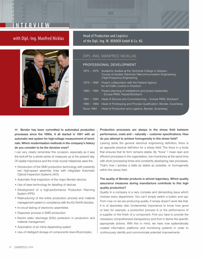
Exclusive interview with Dipl.-Ing. Manfred Nicklas 34Head of Production and Logisticsof the Dipl.-Ing. W. Bender GmbH & Co. KG
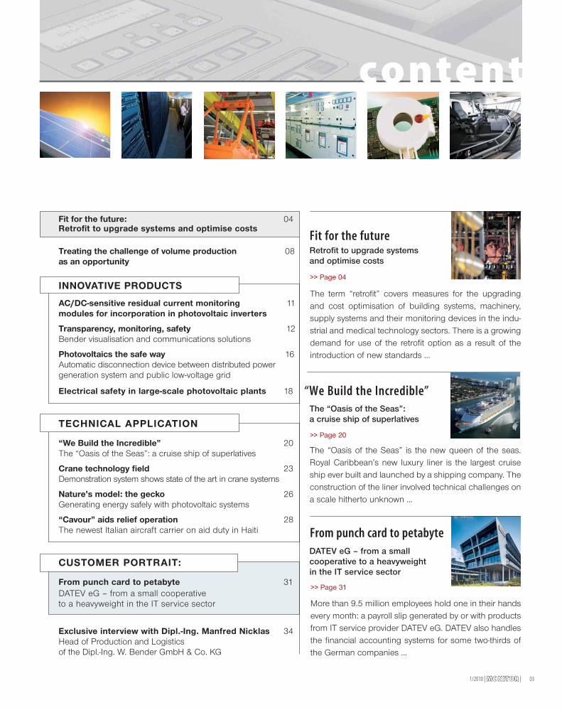
More than 9.5 million employees hold one in their handsevery month: a payroll slip generated by or with productsfrom IT service provider DATEV eG. DATEV also handlesthe financial accounting systems for some two-thirds ofthe German companies ...
The “Oasis of the Seas” is the new queen of the seas.Royal Caribbean’s new luxury liner is the largest cruiseship ever built and launched by a shipping company. Theconstruction of the liner involved technical challenges ona scale hitherto unknown ...
From punch card to petabyte
“We Build the Incredible”
>> Page 20
The term “retrofit” covers measures for the upgradingand cost optimisation of building systems, machinery,supply systems and their monitoring devices in the indu-strial and medical technology sectors. There is a growingdemand for use of the retrofit option as a result of theintroduction of new standards ...
Fit for the futureRetrofit to upgrade systemsand optimise costs
content
>> Page 04
DATEV eG – from a smallcooperative to a heavyweightin the IT service sector
>> Page 31
1/2010 | MONITORMONITOR |
The “Oasis of the Seas”:a cruise ship of superlatives
| MONITORMONITOR | 1/201004
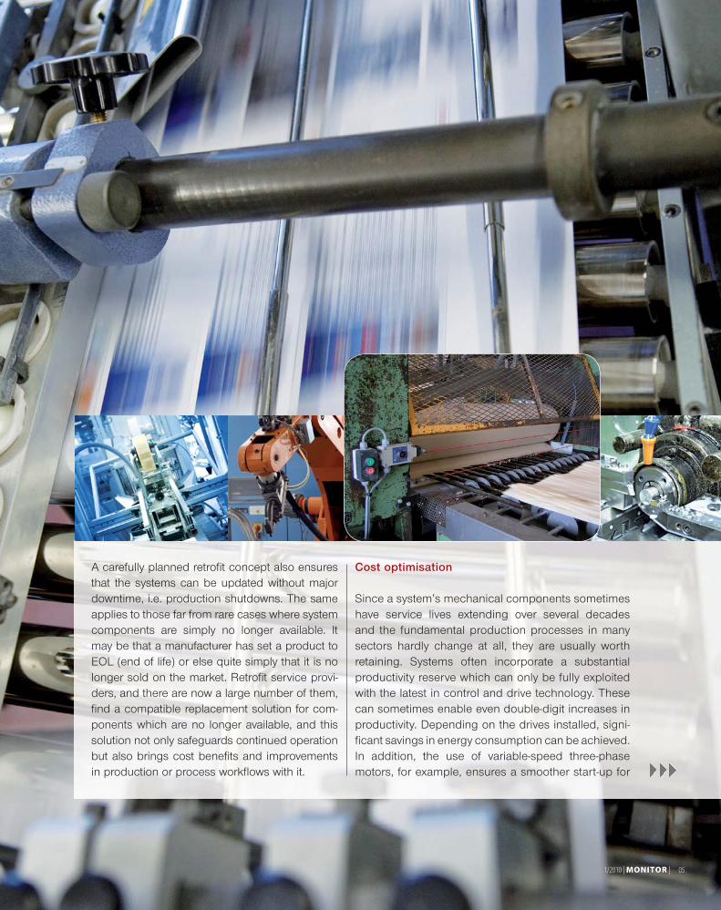
>> The term “retrofit” covers measures forthe upgrading and cost optimisation ofbuilding systems, machinery, supply systemsand their monitoring devices in the industrialand medical technology sectors. There is agrowing demand for use of the retrofit optionas a result of the introduction of new stan-dards, the continued practice of relocatingproduction systems and also, for sometime now, under the pressure of restrictedinvestment potential in the wake of the globaleconomic crisis. Significant cost savings andprocess optimisations can be achieved inproduction operations, on the one hand, whilemeeting the requirements of standards andregulations, on the other hand.
There are a number of goals for retrofit measures:they are intended to ensure safe, reliable systemoperation, to guarantee system installation incompliance with standards and regulationsand, not least, to increase the efficiency of
an existing system. By extending theoriginally planned service life, retrofitmeasures allow cost-optimised opera-tions to be achieved, with grandfatherrights being maintained under certainconditions.
The evergreen option: retrofit
The opening-up of new markets ormarket shifts (relocations), the introductionof new technologies, limited room for
manoeuvre in terms of investment, andconstantly changing safety and operatio-nal standards and regulations all ensurethat there will always be a demand forretrofit services. The efficiency of oldermachinery which is still in good condi-tion mechanically, but whose drive andautomation systems no longer measureup to the state of the art, can sometimesbe substantially increased beyond itsoriginal production level by upgradingthe drive and control technology. Theresulting cost savings over a completelynew installation, taking account in parti-cular of grandfather rights, can be consi-derable. Taking a machine as an examp-le, savings on the equipment alone canbe estimated at 30 - 60% compared witha completely new installation. This doesnot include the savings in terms of space,planning, working time and the buildingfor a completely new installation.
Fit for the future
F E AT U R E
Retrofit to upgrade systems and optimise costs
1/2010 | MONITORMONITOR | 05
A carefully planned retrofit concept also ensuresthat the systems can be updated without majordowntime, i.e. production shutdowns. The sameapplies to those far from rare cases where systemcomponents are simply no longer available. Itmay be that a manufacturer has set a product toEOL (end of life) or else quite simply that it is nolonger sold on the market. Retrofit service provi-ders, and there are now a large number of them,find a compatible replacement solution for com-ponents which are no longer available, and thissolution not only safeguards continued operationbut also brings cost benefits and improvementsin production or process workflows with it.
Cost optimisation
Since a system’s mechanical components sometimeshave service lives extending over several decadesand the fundamental production processes in manysectors hardly change at all, they are usually worthretaining. Systems often incorporate a substantialproductivity reserve which can only be fully exploitedwith the latest in control and drive technology. Thesecan sometimes enable even double-digit increases inproductivity. Depending on the drives installed, signi-ficant savings in energy consumption can be achieved.In addition, the use of variable-speed three-phasemotors, for example, ensures a smoother start-up for
06 | MONITORMONITOR | 1/2010
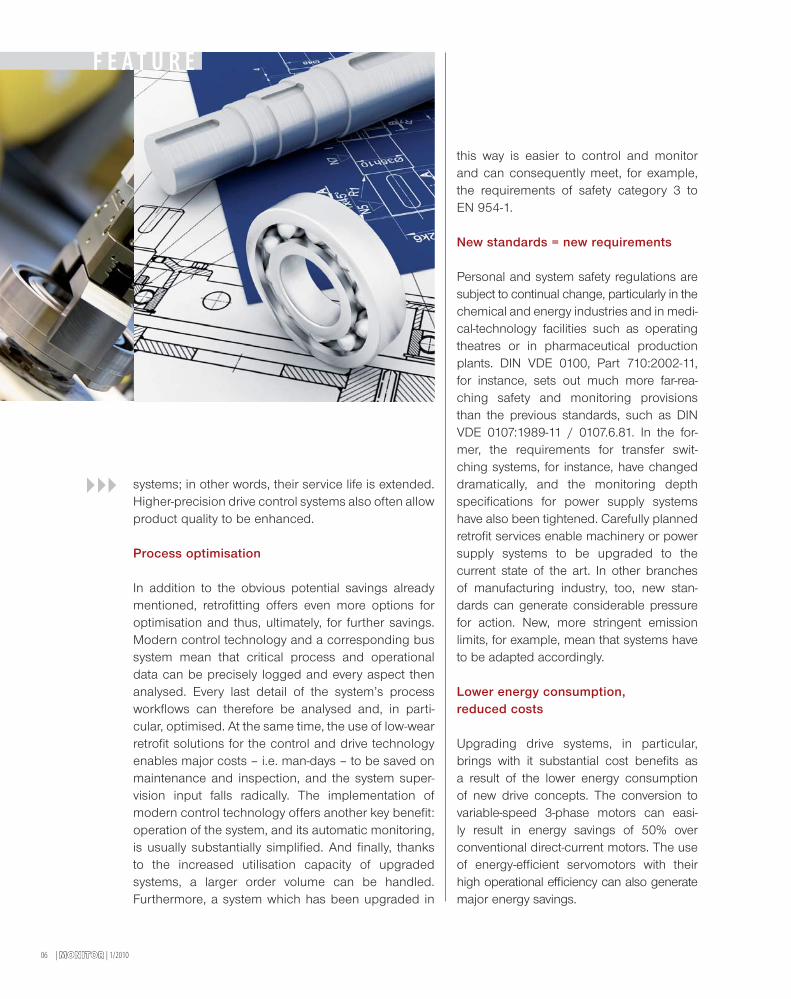
systems; in other words, their service life is extended.Higher-precision drive control systems also often allowproduct quality to be enhanced.
Process optimisation
In addition to the obvious potential savings alreadymentioned, retrofitting offers even more options foroptimisation and thus, ultimately, for further savings.Modern control technology and a corresponding bussystem mean that critical process and operationaldata can be precisely logged and every aspect thenanalysed. Every last detail of the system’s processworkflows can therefore be analysed and, in parti-cular, optimised. At the same time, the use of low-wearretrofit solutions for the control and drive technologyenables major costs – i.e. man-days – to be saved onmaintenance and inspection, and the system super-vision input falls radically. The implementation ofmodern control technology offers another key benefit:operation of the system, and its automatic monitoring,is usually substantially simplified. And finally, thanksto the increased utilisation capacity of upgradedsystems, a larger order volume can be handled.Furthermore, a system which has been upgraded in
F E AT U R E
this way is easier to control and monitorand can consequently meet, for example,the requirements of safety category 3 toEN 954-1.
New standards = new requirements
Personal and system safety regulations aresubject to continual change, particularly in thechemical and energy industries and in medi-cal-technology facilities such as operatingtheatres or in pharmaceutical productionplants. DIN VDE 0100, Part 710:2002-11,for instance, sets out much more far-rea-ching safety and monitoring provisionsthan the previous standards, such as DINVDE 0107:1989-11 / 0107.6.81. In the for-mer, the requirements for transfer swit-ching systems, for instance, have changeddramatically, and the monitoring depthspecifications for power supply systemshave also been tightened. Carefully plannedretrofit services enable machinery or powersupply systems to be upgraded to thecurrent state of the art. In other branchesof manufacturing industry, too, new stan-dards can generate considerable pressurefor action. New, more stringent emissionlimits, for example, mean that systems haveto be adapted accordingly.
Lower energy consumption,reduced costs
Upgrading drive systems, in particular,brings with it substantial cost benefits asa result of the lower energy consumptionof new drive concepts. The conversion tovariable-speed 3-phase motors can easi-ly result in energy savings of 50% overconventional direct-current motors. The useof energy-efficient servomotors with theirhigh operational efficiency can also generatemajor energy savings.
1/2010 | MONITORMONITOR | 07
SUMMARY OF ADVANTAGES:
COST BENEFITS
> Faster return on investment
> No new installation site required
> Lower staff training requirement sincemachine is largely familiar
> Warranty as for a new machine
> Extended service life
> Reduced operating costs
> Lower energy costs, depending on installation
> Increased productivity (reduction in downtimeand shorter cycle times).
PROCESS BENEFITS
> Greater system reliability
> Higher electromagnetic compatibility (no spurious tripping)
> More precise measurements / process analysis
> Enhanced personal and system safety
> Updated, simplified operating structure
> Greater functionality (networking capability via bus system)
> No new and therefore protracted approval process
> Enhanced quality thanks to greater system precision
> No changes in media supply and disposal
> Existing spare parts can continue to be used.
Wishlist:
> Compliance with current occupational health andsafety standards
> Increased production output
> New machines to expand production facilities
> Installation of new automation technology
> More wear-resistant materials than hitherto
> Optimised workflows and processes
> Replacement of assemblies for which componentsare no longer available
> Significant energy savings (up to 50%) e.g. throughuse of frequency converters
> In very general terms, reduced production costs.
If any of these are on your wishlist, there is no wayof avoiding the retrofit issue. And one of the decisivefeatures of retrofitting is the multiple benefits that itautomatically entails. Even if you only have one preciselydefined reason for a retrofit measure (e.g. adaptation tocurrent standards because of insurance-related require-ments), it will always deliver a number of advantages.
Who plans wins
However, careful and competent planning isabsolutely crucial to the success of a retrofitmeasure! From the conscientious appraisal ofthe system and the clear description of therequired processes, via expert technical analysisto a detailed, authoritative cost analysis: only ifall the individual stages are carried out preciselyis it possible to carry out upgrades to machinerysystems within the shortest possible time andwith the desired target results. It is essential,therefore, for anyone considering the retrofitoption, to call on the services of planners whoare technically skilled and, in particular, haveexperience in implementing such actions. If thisphase, which makes the difference betweensuccess and failure, is carried out in ideal fashion,everything is in place for new technology tohelp old systems operate with more efficiency,reliability and safety.
Timothy Hörl, Dreipass
| MONITORMONITOR | 1/201008
Treating the challengeof volume production as an opportunity
N E W S
Benefit of experience and breaking new ground
Bender’s successful business model is closely linked withtechnical solutions for very customer-specific applications.That places high demands on the flexibility of the develop-ment, production and logistics processes and requires closecooperation with customers to ensure that the process andproduct quality for small and extremely small quantities ismaintained.
Bender’s entry into the field of photovoltaics made newdemands on the company in this regard. These include:
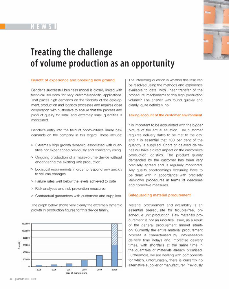
> Extremely high growth dynamic, associated with quan-tities not experienced previously and constantly rising
> Ongoing production of a mass-volume device withoutendangering the existing unit production
> Logistical requirements in order to respond very quicklyto volume changes
> Failure rates well below the levels achieved to date
> Risk analyses and risk prevention measures
> Contractual guarantees with customers and suppliers.
The graph below shows very clearly the extremely dynamicgrowth in production figures for this device family.
The interesting question is whether this task canbe resolved using the methods and experienceavailable to date, with linear transfer of theprocedural mechanisms to this high productionvolume? The answer was found quickly andclearly: quite definitely, no!
Taking account of the customer environment
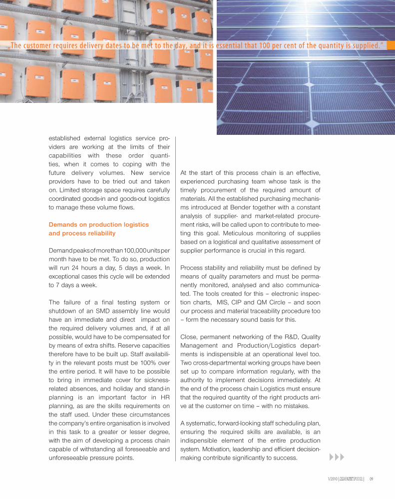
It is important to be acquainted with the biggerpicture of the actual situation. The customerrequires delivery dates to be met to the day,and it is essential that 100 per cent of thequantity is supplied. Short or delayed delive-ries will have a direct impact on the customer’sproduction logistics. The product qualitydemanded by the customer has been veryprecisely agreed and is regularly monitored.Any quality shortcomings occurring have tobe dealt with in accordance with preciselylaid-down procedures in terms of deadlinesand corrective measures.
Safeguarding material procurement
Material procurement and availability is anessential prerequisite for trouble-free, on-schedule unit production. Raw materials pro-curement is not an uncritical issue, as a resultof the general procurement market situati-on. Currently the entire material procurementprocess is characterised by unforeseeabledelivery time delays and imprecise deliverytimes, with shortfalls at the same time inthe quantities of materials already promised.Furthermore, we are dealing with componentsfor which, unfortunately, there is currently noalternative supplier or manufacturer. Previously
Year of manufacture
Qua
ntit
y
091/2010 | MONITORMONITOR |
established external logistics service pro-viders are working at the limits of theircapabilities with these order quanti-ties, when it comes to coping with thefuture delivery volumes. New serviceproviders have to be tried out and takenon. Limited storage space requires carefullycoordinated goods-in and goods-out logisticsto manage these volume flows.
Demands on production logisticsand process reliability
Demandpeaksofmorethan100,000unitspermonth have to be met. To do so, productionwill run 24 hours a day, 5 days a week. Inexceptional cases this cycle will be extendedto 7 days a week.
The failure of a final testing system orshutdown of an SMD assembly line wouldhave an immediate and direct impact onthe required delivery volumes and, if at allpossible, would have to be compensated forby means of extra shifts. Reserve capacitiestherefore have to be built up. Staff availabili-ty in the relevant posts must be 100% overthe entire period. It will have to be possibleto bring in immediate cover for sickness-related absences, and holiday and stand-inplanning is an important factor in HRplanning, as are the skills requirements onthe staff used. Under these circumstancesthe company’s entire organisation is involvedin this task to a greater or lesser degree,with the aim of developing a process chaincapable of withstanding all foreseeable andunforeseeable pressure points.
At the start of this process chain is an effective,experienced purchasing team whose task is thetimely procurement of the required amount ofmaterials. All the established purchasing mechanis-ms introduced at Bender together with a constantanalysis of supplier- and market-related procure-ment risks, will be called upon to contribute to mee-ting this goal. Meticulous monitoring of suppliesbased on a logistical and qualitative assessment ofsupplier performance is crucial in this regard.
Process stability and reliability must be defined bymeans of quality parameters and must be perma-nently monitored, analysed and also communica-ted. The tools created for this – electronic inspec-tion charts, MIS, CIP and QM Circle – and soonour process and material traceability procedure too– form the necessary sound basis for this.
Close, permanent networking of the R&D, QualityManagement and Production/Logistics depart-ments is indispensible at an operational level too.Two cross-departmental working groups have beenset up to compare information regularly, with theauthority to implement decisions immediately. Atthe end of the process chain Logistics must ensurethat the required quantity of the right products arri-ve at the customer on time – with no mistakes.
A systematic, forward-looking staff scheduling plan,ensuring the required skills are available, is anindispensible element of the entire productionsystem. Motivation, leadership and efficient decision-making contribute significantly to success.
„The customer requires delivery dates to be met to the day, and it is essential that 100 per cent of the quantity is supplied.”
| MONITORMONITOR | 1/201010
Measures for ensuring processand product quality
The entire process chain was analysed in 2009, andtargets and key performance indicators for potentialimprovements were then set. These included, in particular:
> Ongoing, prompt monitoring of external and internalshortfall statistics
> Close integration of suppliers in quality specifications
> Analysis and modification of test stations and testroutines
> Air-conditioning of test rooms
> Key performance indicators for FPY (First Pass Yield)
> Analysis and shortening of test times
> Creation of resources for immediate fault appraisal
> Visualisation of current quality status
> Appointment of a specific team of employees to
inspect units with regular training
> Regular QM meetings to address current quality status
> Regular information to Board of Directors on currentquality status.
Reducing test times and improving the FPY are, ofcourse, ongoing quality targets for all units. But what dothese performance indicators actually mean for a volumeproduction of 1,000,000 units? In specific terms, impro-ving the FPY by 1% means reducing the test time resour-ce by 200h; in other words: a saving of 25 shifts at a testbench can be made.
Finally, we need to mention the cooperation with staff.The overall goal, i.e. meeting the customer order, can onlybe achieved if the processes, quality and staff attitudesare working together towards this goal. The appointmentof the test team, together with ongoing training on testsequences, failure rates, effects of faults etc., representeda new way of improving staff motivation and identification.
Planned and necessary activities for 2010
The measures and activities described so farare not enough in themselves to guaranteeour delivery capability with a growing volume.Aspects still to be resolved are the ongoingmaterial provision, the increase in the testcapacity and the quality improvement for a keycomponent.
In the short term, the purchase and commis-sioning of 3 further test stations are necessary.However, this also means that further staff haveto be planned, trained and deployed. Thesetest stations will have to be implemented whileproduction is already in progress. This willrequire a high level of commitment from thestaff.
Outlook and prospects
Long-run production is, without doubt, a hugechallenge for our people, machines and pro-cesses. The capabilities of our established pro-cedures and newly introduced methods andprocesses are being put to the test.
The major opportunity for us is to identifynew improvement levers while faced with thechallenge of real volume production. All ourstaff have faced up to these requirements, andour experience to date has been very positive,even if some processes have undergone radicalchange.
Long-run production is breaking new groundfor the future, for new applications and fornew customers. It is generating expertise andexperience in the company.
Dipl.-Ing. Manfred Nicklas, Head of Production and LogisticsDipl.-Ing. Andreas Förster, Head of Quality Management
N E W S
1/2010 | MONITORMONITOR | 11
I N NOVAT I V E P RODU C T S
System AND personal protectionIn order to guarantee both protection by electricalseparation and also additional personal protection,DIN V VDE V 0126-1-1:2006-02 specifies that trans-formerless inverters (without electrical separation)must have a residual current monitoring unit (RCMU).If, as a result of an insulation fault, e.g. defectiveinsulation, contact occurs between a live cable anda grounded person, a dangerous shock currentcan flow. The residual current is made up of thegeometric addition of the fault current (ohmic load)and the capacitive discharge current (capacitiveload). The system leakage capacitance must not beignored, as this can be as much as 5 - 50 nF (permodule) to ground.
DIN V VDE V 0126-1-1: 2006-02 specifies that theoccurrence of a fault current between the solargenerator and the feed-in grid must result in thephotovoltaic inverter being shut down in accordancewith the criteria set out in Table 1.
Furthermore, shutdown within 0.3 s is mandatory in theevent of continuously rising or permanent leakage currents(> 300 mA). Permanent residual current monitoring via anRCMU is therefore absolutely essential.
Robust and reliableThe demands on the monitoring technology are tough: TheRCMA278P-S / RCMA126P1-S AC/DC-sensitive residualcurrent monitoring modules are unaffected by externalinfluences and meet the most stringent standards in termsof temperature stability.
Flexible and exactRCMA278P-S / RCMA126P1-S modules detect AC andDC fault currents in the range 0 - 100 mA (0 - 100 Hz). Thecurrent is measured and is available in the RCMA278P-S asa proportional DC voltage at the module output for furtherprocessing in the inverter. The RCMA126P1-S detectsresidual currents in the range 0 - 30 / 100 mA (0 - 500 Hz).A proportional PWM signal is available at the module outputfor further processing in the inverter.
The RCMA126P1-S / RCMA278P-S boards can easily bebonded and affixed to an inverter board using solder pinsand a mechanical latch.
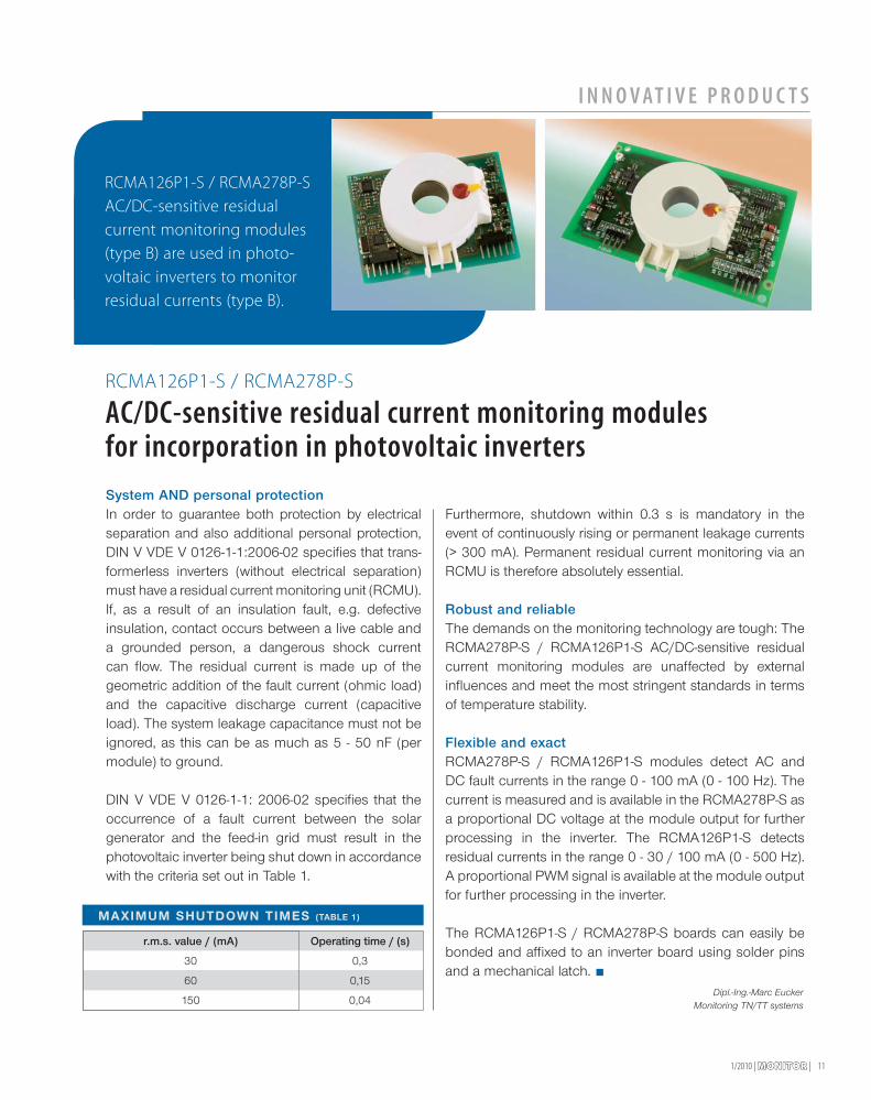
RCMA126P1-S / RCMA278P-S
AC/DC-sensitive residual current monitoring modulesfor incorporation in photovoltaic inverters
RCMA126P1-S / RCMA278P-S
AC/DC-sensitive residual
current monitoring modules
(type B) are used in photo-
voltaic inverters to monitor
residual currents (type B).
Dipl.-Ing.-Marc EuckerMonitoring TN/TT systems
MAXIMUM SHUTDOWN TIMES (TABLE 1)
Operating time / (s)
0,3
0,15
0,04
r.m.s. value / (mA)
30
60
150
| MONITORMONITOR | 1/201012
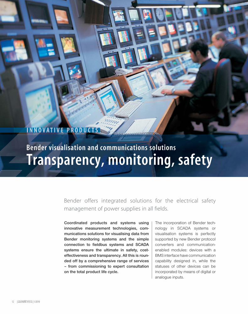
Bender offers integrated solutions for the electrical safety
management of power supplies in all fields.
Coordinated products and systems usinginnovative measurement technologies, com-munications solutions for visualising data fromBender monitoring systems and the simpleconnection to fieldbus systems and SCADAsystems ensure the ultimate in safety, cost-effectiveness and transparency. All this is roun-ded off by a comprehensive range of services– from commissioning to expert consultationon the total product life cycle.
The incorporation of Bender tech-nology in SCADA systems orvisualisation systems is perfectlysupported by new Bender protocolconverters and communication-enabled modules: devices with aBMS interface have communicationcapability designed in, while thestatuses of other devices can beincorporated by means of digital oranalogue inputs.
Transparency, monitoring, safetyBender visualisation and communications solutions
132/09 | MONITORMONITOR |
KUNDENPORTRA IT
Modern communication
The use of modern fieldbus and network tech-nologies has become essential in the field ofautomation of electrical systems because therequirements relating to communication capa-bilities data availability and flexibility are risingconstantly. For example, operating, warning orfault messages via the IP network or the web helpto enhance power supply transparency and atthe same time permit a rapid response to criticaloperating states. Important messages can alsobe transmitted in parallel via SMS or e-mail to theservice technician’s mobile phone or laptop. Earlyinformation on the location and cause enablesservice calls to be optimised in terms of time,costs and staff and may also enable a systemfailure or the destruction of expensive equipmentto be avoided.
BMS busBender’s communication-capable devices andsystems are equipped with the BMS bus. The BMSbus (the name is derived from the German languagefor Bender measuring device interface) is an in-house development by Bender which optimisesdata transfer between all communication-capableBender products. The BMS bus is based onthe RS-485 interface, which has been proven inmillions of applications, with one master andmultiple slaves. It has a hierarchical structure,termed the internal and external BMS bus.
Advantages at a glance
• Reliableandconvenientmonitoring,surveillanceand remote display of electrical functions
• Highly flexible in the event of expansions andchanges in use
• Simple project planning thanks to clear projectstructure
• Scalable: up to 99 x 139 devices possible in asystem.
Bender communications solutions:
Ethernet / TCP/IP connectionEthernet technology goes back to developments from1973. Since the 1990s it has become the most widelyused LAN (local area network) technology. Ethernetis used now as the basis for many network protocols,e.g. AppleTalk, DECnet, IPX/SPX and TCP/IP. As anon-manufacturer-specific technology it transfers dataat a scalable speed. The internet protocol IP now formsthe basis for application protocols such as HTTP, FTP,SNMP and Modbus/TCP. The main benefit for theuser is the simple integration of the industrial Ethernetdevices in higher-level IT and management systems.
TRA ITTRA IT”The requirements relating to communication capabilities data availability and flexibility are rising constantly.”
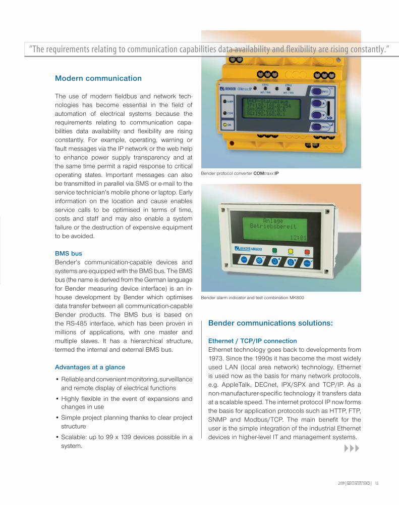
Bender protocol converter COMtraxx:IP
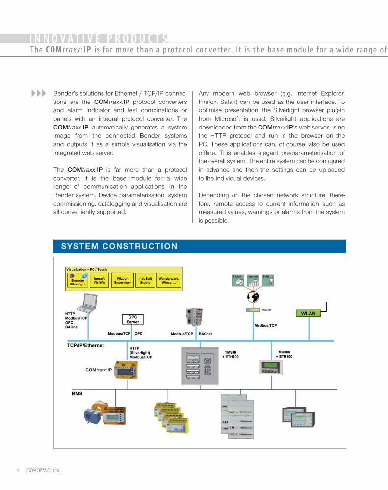
Bender alarm indicator and test combination MK800
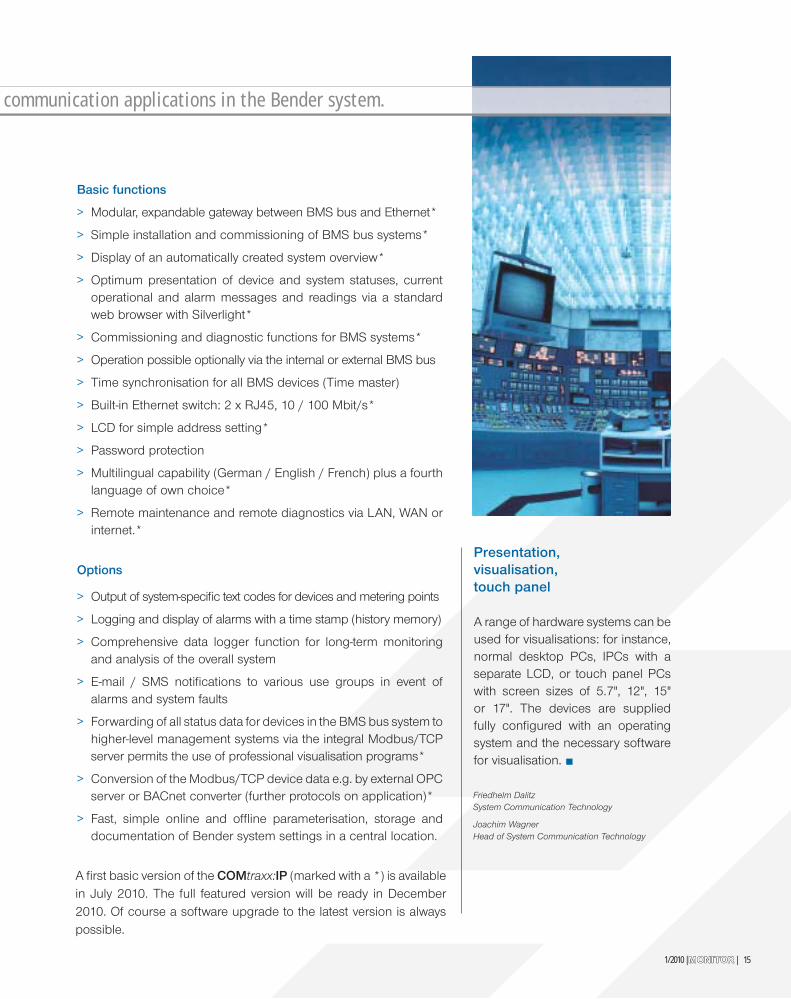
Bender’s solutions for Ethernet / TCP/IP connec-tions are the COMtraxx:IP protocol convertersand alarm indicator and test combinations orpanels with an integral protocol converter. TheCOMtraxx:IP automatically generates a systemimage from the connected Bender systemsand outputs it as a simple visualisation via theintegrated web server.
The COMtraxx:IP is far more than a protocolconverter. It is the base module for a widerange of communication applications in theBender system. Device parameterisation, systemcommissioning, datalogging and visualisation areall conveniently supported.
Any modern web browser (e.g. Internet Explorer,Firefox, Safari) can be used as the user interface. Tooptimise presentation, the Silverlight browser plug-infrom Microsoft is used. Silverlight applications aredownloaded from the COMtraxx:IP’s web server usingthe HTTP protocol and run in the browser on thePC. These applications can, of course, also be usedoffline. This enables elegant pre-parameterisation ofthe overall system. The entire system can be configuredin advance and then the settings can be uploadedto the individual devices.
Depending on the chosen network structure, there-fore, remote access to current information such asmeasured values, warnings or alarms from the systemis possible.
SYSTEM CONSTRUCTION
| MONITORMONITOR | 1/201014
I N N O V AT I V E P R O D U C T SThe COMtraxx :IP is far more than a protocol converter . I t i s the base module for a wide range of c
Basic functions
> Modular, expandable gateway between BMS bus and Ethernet*
> Simple installation and commissioning of BMS bus systems*
> Display of an automatically created system overview*
> Optimum presentation of device and system statuses, current operational and alarm messages and readings via a standard web browser with Silverlight*
> Commissioning and diagnostic functions for BMS systems*
> Operation possible optionally via the internal or external BMS bus
> Time synchronisation for all BMS devices (Time master)
> Built-in Ethernet switch: 2 x RJ45, 10 / 100 Mbit/s*
> LCD for simple address setting*
> Password protection
> Multilingual capability (German / English / French) plus a fourth language of own choice*
> Remote maintenance and remote diagnostics via LAN, WAN or internet.*
Options
> Output of system-specifi c text codes for devices and metering points
> Logging and display of alarms with a time stamp (history memory)
> Comprehensive data logger function for long-term monitoring and analysis of the overall system
> E-mail / SMS notifi cations to various use groups in event of alarms and system faults
> Forwarding of all status data for devices in the BMS bus system to higher-level management systems via the integral Modbus/TCP server permits the use of professional visualisation programs*
> Conversion of the Modbus/TCP device data e.g. by external OPC server or BACnet converter (further protocols on application)*
> Fast, simple online and offl ine parameterisation, storage and documentation of Bender system settings in a central location.
Presentation, visualisation, touch panel
A range of hardware systems can be used for visualisations: for instance, normal desktop PCs, IPCs with a separate LCD, or touch panel PCs with screen sizes of 5.7", 12", 15" or 17". The devices are supplied fully confi gured with an operating system and the necessary software for visualisation.
Friedhelm DalitzSystem Communication Technology
Joachim WagnerHead of System Communication Technology
1/2010 | MONITORMONITOR | 15
communicat ion appl icat ions in the Bender system.
A fi rst basic version of the COMtraxx:IP (marked with a *) is available in July 2010. The full featured version will be ready in December 2010. Of course a software upgrade to the latest version is always possible.

| MONITORMONITOR | 1/201016
>> More and more distributed power generationsystems in the power range >30 kW are feeding elec-tricity into the public low-voltage grid, and the trend ismost definitely upwards. However, grid operators arealso faced with a number of problems from privatepower generators.
Automatic disconnection device
Until now PV systems were connected to the low-voltagegrid in accordance with draft standard DIN VDE 0126from 1999. This standard defines the requirements fora safety interface between PV systems and the publiclow-voltage grid, which can be used as a substitutefor a disconnection device which is available any timeto the grid operator. This standard is known by theabbreviation “ENS”.
During its use, however, a number of technical problemsoccurred, primarily relating to the monitoring of thegrid impedance. These problems resulted in spuriousshutdowns and thus to reduced power yields fromthe respective system. Working group DKE 373.0.9“Bidirectional grid interface” was set up in response,tasked with redefining the necessary requirements.
The bidirectional safety interface in accordance withthe new standard DIN V VDE V 0126-1-1:2006-02 is stillused between the distributed power generation systemand the low-voltage grid. Three test methods for grid dis-connection and monitoring are possible. One of these isfrequency and voltage monitoring, in addition to measu-ring the grid impedance and the resonant circuit.
Frequency and voltage monitoring
The thresholds specified in DIN V VDE V0126 1-1 for frequency and voltage, set outa frequency range from 47.5 Hz to 50.2 Hzand a voltage range from 80 to 115% ofthe rated voltage. The permissible voltagerange therefore lies between 184 V and 264V, though the required voltage and frequen-cy ranges can be defined by the electricitysupply companies outside the specificati-ons of DIN 0126-1-1 in special cases. In theevent of non-compliance with the permissib-le voltage and frequency ranges, the systemis required to shut down within 200 ms. Inprinciple, a 30-second tolerance range testto ensure compliance with the limit valuesmust be carried out prior to connecting to
Automatic disconnection device between distributed powergeneration system and public low-voltage grid
Photovoltaics the safe way
Despite the sector’s rapid growth, photovoltaics is still relatively in its infan-cy. In principle, the sun provides enough energy – for everyone. An outputof 1.36 kW/m2 constantly strikes the Earth’s outer atmosphere. To convertthis energy into electricity even more efficiently presents a challenge tophotovoltaic systems.
Bender VMD423

1/2010 | MONITORMONITOR | 17
the grid. This specified requirement must be met aftereach failure to comply with a limit value.
In order to satisfy the electricity supply companies’specifications, the VMD422(H) can be adapted to allrequirements and can also be used in problematicalgrid ranges. A VMD423(H) can be used on thesecondary side of the voltage transformer used inmedium-voltage systems, ensuring safe and reliablegrid disconnection within 80 ms in the event of non-compliance with the limit values.
The graphic below shows the connection of theVMD422/VMD423. The units are always connectedon the grid side. In the event of non-compliance withvoltage and frequency limit values or islanding, thedistributed power generation system is disconnectedfrom the public grid.
Features of the public low-voltage grid
The definition of the permissible voltage range isregarded as uncritical. On the other hand, the verylimited frequency range, particularly the overfrequencyspecification of 50.2 Hz, is criticised. In the currentstandard, however, the compatibility with DIN EN 50160,which describes the voltage and frequency quality inthe public low-voltage grid, has been improved.
It should be noted that there is a 99.5 % probabilityof the grid frequency in an annual average beingbetween 49.5 Hz and 50.5 Hz . The lower frequency of47.5 Hz as specified in the standard is therefore in linewith practical conditions. However, the overfrequencies
from DIN V VDE V 0126-1-1 and DIN EN 50160 donot match. Grid frequencies >50.2 Hz therefore resultin disconnection of the distributed power generationsystem from the public low-voltage grid.
Critical states
Automatic reclosing and discharge faults (lightningstrikes) are critical since the resulting voltage faultscan damage distributed power generation systems.They subject the generator’s voltage-generatingwinding to a brief load and can have an impact on allthree phases within a grid period.
A fundamental requirement of DIN V VDE V 0126-1-1is the detection of islanding which represents asignificant safety risk. Islanding can occur as a resultof switching operations by the grid operators, thetripping of protective systems or equipment failures.This is termed accidental or unintentional islanding.In such cases, the grid operator loses control of thesub-network. As a result, the grid, which is assumedto be shut down, can cause personal injury, amongother problems.
On the safe side
The transient frequency spikes above 50.2 Hz arereliably detected by Bender’s VMD422 and VMD423units and do not necessarily result in disconnection ofthe system from the low-voltage grid since the shut-down time of 200 ms specified in DIN V VDE V 0126-1-1is met. In the event of a failure to comply with the per-missible voltage and frequency ranges, and if islandingis detected or dangerous discharge faults occur, thesystem is immediately and safely disconnected.
In its current VMD422 und VMD423 frequency andvoltage monitors, which have been specially designedfor use in monitoring distributed power generationsystems, Bender offers the ideal solution and there-fore meets the stringent requirements on monitoringtechnology.
BLOCK DIAGRAM VMD422/VMD423
Dipl.-Ing. Marc Euker, Monitoring TN/TT Systems
Photovoltaicsystem
Supply to thepublic grid

18 | MONITORMONITOR | 1/2010
I N N O V A T I V E P R O D U C T S
Die Sonne möglichst effizient nutzen – das ist das Ziel eines jeden
Betreibers einer Photovoltaikanlage. Die hohe Produktivität einer PV-Anlage
ist jedoch unmittelbar mit dem Wunsch verbunden, eine Abschaltung bei
einem ersten Isolationsfehler zu vermeiden und trotzdem die notwendige
Sicherheit zu gewährleisten.
>> For this reason the IT system with insulationmonitoring devices according to IEC 60364-4-41:2005is applied on the DC side. The following applicationreport shows the practical implementation of thisstandard in a photovoltaic system.
Design of the photovoltaic system
A photovoltaic system is a solar power plant in whichsolar radiation is converted into electrical energy bymeans of photovoltaic cells. Depending on the systemsize and type, the individual solar modules are connectedinto so-called strings which are in turn connectedinto arrays. The DC voltage generated is convertedinto mains-compliant AC voltage using one or moreinverters.
The photovoltaic system described has a total outputof 2.7 MW. It consists of 5 arrays which are eachconnected to a central inverter with a rated output of
540 kW. Thin-film modules (no TCO corrosion)are used as the photovoltaic modules. Tenmodules at a time are connected to form onestring; 720 of these strings are connected inturn to an inverter. This means 7,200 photo-voltaic modules feed one inverter. In total,36,000 photovoltaic modules are spread overan area of 5 ha land.
IT system as success factor
The productivity of a photovoltaic system canonly be guaranteed if, among other factors, thesystem availability is very high and a potentialinsulation fault location is both time andcost efficient. This aspect is addressed byselecting an IT system for the DC-side ofa system configuration. This reduces costsfor maintenance, servicing and outage andminimises downtime.
Utilizing the sun most efficiently – that
is the goal of a photovoltaic system.
In order to maintain productivity of a
photovoltaic system at a high level, a
shutdown at a first insulation fault is to be
avoided; at the same time the necessary
protection of persons and the system
must be ensured.
Electrical safetyin large-scale photovoltaic plants

191/2010 | MONITORMONITOR |
! SUMMING-UP
The secondary side of the inverter feeds into a trans-former, by means of which the voltage is transformedto the medium-voltage system. Since, as a result, noactive conductor is connected to earth; the necessa-ry conditions are in place for an unearthed system(IT system). Hence, should an insulation fault orshort-circuit to earth occur now, there is neither ashort-circuit current nor tripping of the upstreamfuse; system operation continues uninterruptedly.The fundamental requirements no failure in the eventof a first insulation fault as well as operation and fireprotection, are being met with the protective measureof the IT system with insulation monitoring. At thesame time, the protection of persons is enhanced,since there is only small direct current without ACripple applied at the modules.
Insulation monitoring
In order to detect deterioration of the insulation at anearly stage, an insulation monitoring device in accor-dance with IEC 60364-4-41:2005 is installed foreach inverter. This monitors the insulation resistancefrom the module to the transformer according tothe requirements of IEC 61557-8:2007. This devicehas a special measurement method which consi-ders the particular features of photovoltaic systems.This includes for example the consideration of thesystem leakage capacitances up to 1 000 µF andsystem direct voltages up to 1 500 V d.c. Approx.5 to 100 nF per module can be applied as typicalcapacitance Ce for thin-film modules, this means aminimum value of approx. 50 µF for 10,000 modules.
In practice, the total insulation resistance – despitethe Protection Class II modules – between systemand earth fluctuates at night and during the day.In the morning it falls, which is attributable to thecondensation on the modules and the resistanceproperties of the thin-film modules. In principle, theinsulation resistance of a thin-film module is in therange from 500 MΩ to 2 GΩ. Taking account of thereduction in insulation resistance in the morning,Bender recommends setting the response value Ran
in accordance with the following formula:
Speedy fault location, minimal costs
With the erecting of so many modules, identifying a faultyphotovoltaic module requires a a lot of time and a largecost input. The installation of a system to detect insulationfaults is therefore an obvious step. This consists of alocating current injector PGH, a stationary insulation faultevaluator EDS460 and a portable insulation fault locationsystem for unearthed systems (IT system) EDS190. Themeasuring current transformers of the stationary insulationfault evaluators are each assigned to one string. Thisenables the faulty string to be identified in less thana minute. Using the portable insulation fault locationsystem, it is then possible to locate the faulty module onsite. This portable insulation fault location system has twomeasuring clamps, so that fast fault location is possibleeven with separate conductors (+/-). This system meetsthe requirements according to IEC 61557-9:2009.
The application of the protective measure IT system withinsulation monitoring in combination with a system forinsulation fault location, the protection of persons andthe system is not only ensured, this system is also cost-effective. In this way the goals of the system operators areimplemented altogether in a practice-oriented manner:
> Early detection of possible hazards
> Reducing the down-time risk to a minimum
> Ensuring the system availability.
Wolfgang Hofheinz, CTO, TechnologyOliver Schäfer, Monitoring IT Systems
Harald Sellner, Technical Marketing
Principle of preventive electrical safety

| MONITORMONITOR | 1/201020
The “Oasis of the Seas” is the new queen of the seas. Royal Caribbean’s newluxury liner is the largest cruise ship ever built and launched by a shipping company.The construction of the liner involved technical challenges on a scale hithertounknown. Encouraged by their excellent experience with Bender technology, the shipowners once again opted for the reliable electrical solutions offered by the Gruenbergcompany for the construction of this amazing miracle of engineering.
The “Oasis of the Seas”: a cruise ship of superlat ives
“We Build the Incredible”

! INFO
211/2010 | MONITORMONITOR |
>> With an overall length of 361 m,a width of 47 m and a height of 65 m,the ”Oasis of the Seas” has the capa-city to carry 6360 passengers and2100 crew members. The secondship of this class, the “Allure of theSeas”, is scheduled to be deliveredin November. Packed with energy-efficient energy, automation anddrive technologies, the “Oasis ofthe Seas” is not only the largest, butalso the most expensive, comfortab-le and innovative cruise ship in theworld (construction costs approx.900 million euros).
The list of amenities onboard the “Oasisof the Seas” reads like an advertisingbrochure featuring the attractions of amajor tourist destination on shore:> Theatre auditorium with 1358 seats> Aqua theatre with 580 seats> 2 additional stages> 2704 passenger cabins> Casino> 9 restaurants> 8 shops> Large pool (more than 5 m deep)> 20 smaller pools
(some with sandy beaches)> Amusement park> Rock-climbing walls> Parks and gardens> Fitness facilities> Surfing wave pools> Sports courts for ball games> Ice skating rink
> Several areas for young people> Internet connections> Nightclub> Jazz bar> Cinemas.
On 5 December 2009, the “Oasis ofthe Seas” set off to her successfulmaiden voyage from her home portin Fort Lauderdale in Florida (USA).In its first year, the cruise ship willundertake 19 consecutive seven-daysailings in the Caribbean, calling atports in the Bahamas, Jamaica andMexico, amongst others.
Energy and efficiency
The power and process heat for the“Oasis of the Seas“ is supplied bya diesel-powered generator system.This system comprises two groups of
engines, one with three V12-cylin-der engines (each producing 13,860kW) and one with three V16-cylinderengines (each producing 18,480kW). These six medium speed4-stroke Wärtsilä 46 diesel enginesoperate with common rail injectiontechnology, cutting exhaust emissionsignificantly compared to conventionaldiesel generators. For this reasonhardly any exhaust gases are visible,even at full speed. The system’s totaloutput rating is more than 97 MW.
These engines drive three 15,800 kVAgenerators as well as three 21,000kVA generators. The electrical systemwas developed and built by ABB.It includes the six main genera-tors with all necessary switchgear,three drive systems of the ACS6000series with corresponding additional
Impressive key facts:
> Approximately 250 km of piping and 5310 km of electric wiring installed
> Approx. 100,000 power sockets installed on the ship
> 600,000 litres of paint required for the paint finish
> The 21 pools hold approx. 2.3 million litres of water
> 4.1 million litres of fresh water is generated every day
> 12,175 plants exist on board; some trees are more than 7 m high
> The ship's maximum width exceeds the wingspan of an Airbus A340-300
> The ship is more than three times the length of a football pitch.

| MONITORMONITOR | 1/201022
Essential Bender components installedin the “Oasis of the Seas”:> A-ISOMETER® IRDH575 in combi-
nation with EDS460 insulation faultlocation systems for
a) monitoring 440V IT systems in dif-ferent high voltage and emergencypower stations for supplying com-pressors, bilge pumps, sprinklersystems and waste processing,and
b) monitoring 230 V IT systems supp-lying cabin distributions, kitchens,heating, lighting, emergency powerstations and emergency lighting.
> Residual current monitoring systemRCMS460:Formonitoringearthed powersystems(TN-S systems) such as lighting andsocket-outlets in cabins.
During the construction of the “Oasis ofthe Seas” our Finnish representative,Heikki Neumann, visited the shipyard.He offered advice and support tothe designers and machine shops atABB and was always at hand whenquestions or problems needed to besolved. Bender’s presence on siteduring the design and constructionphases was a major reason for theship owners’ overall satisfaction – inaddition to the proven reliability ofthe Bender technology. Our team atBender is proud to have played a partin such an impressive and absolutelyunique monumental engineering pro-ject. “We build the incredible” wasthe ship owners’ project slogan. “Wemake the incredible safe” was ourown mission.
T E CHN I C A L APP L I C AT I ONThe “Oasis of the Seas”: a cruise ship of superlat ives
components, as well as the drivesfor the four bow thrusters. Theemergency power generators aredriven by two 16V4000 MTU dieselengines.
The ship is propelled by three stern-mounted ABB Azipod propellerpods, which can be rotated by360° degrees for steering andmanoeuvring. Each propeller podcontains an electric motor whichtransmits an output of 20 MWdirectly to a five-blade fixed pitchpropeller (diameter 6.1 m) installed
forward-facing in the direction oftravel. In order to provide excellentmobility and manoeuvrability in portsand at low speeds, the ship is equippedwith four bow thrusters with a totaloutput rating of 22 MW.
Proven quality from Bender
The ship of superlatives was built bythe Finnish shipyard “STX FinlandOy” and was designed and con-structed using electrical low voltageswitchboards from ABB LVS inVaasa (Finland). Owing to theirpositive experience with Benderproducts when fitting out the “Voyagerof the Seas”, the ship owners “RoyalCaribbean Cruises Ltd.” decidedonce again to use Bender compon-ents for monitoring important elec-trical circuits installed in the “Oasisof the Sea”. The safety of personsand machinery are of particularconcern when dealing with such hugedimensions and complex structures,especially in a sea-going vessel.
Gigantic voltagedistribution systems– robust systemprotection technology
In addition to the drives, tens of thou-sands of other electrical loads andaround 100,000 power sockets aresupplied with power – using morethan 5300 km of electric cables. Thegenerators feed a 11 kV rail from whichthe various systems are supplied viatransformers. The main power supplyis laid out as a ring, with all importantsystems redundant.
Dipl.-Ing. Harald Sellner, Technical Marketing
231/2010 | MONITORMONITOR |
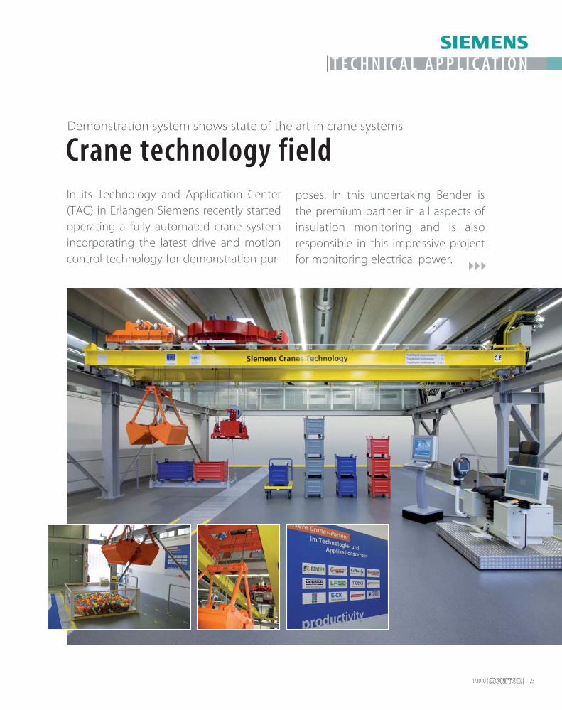
Crane technology fieldDemonstration system shows state of the art in crane systems
T E CHN I C A L APP L I C AT I ON
In its Technology and Application Center(TAC) in Erlangen Siemens recently startedoperating a fully automated crane systemincorporating the latest drive and motioncontrol technology for demonstration pur-
poses. In this undertaking Bender isthe premium partner in all aspects ofinsulation monitoring and is alsoresponsible in this impressive projectfor monitoring electrical power.
| MONITORMONITOR | 1/201024
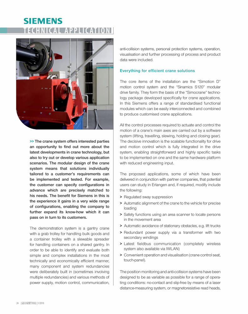
>> The crane system offers interested partiesan opportunity to find out more about thelatest developments in crane technology, butalso to try out or develop various applicationscenarios. The modular design of the cranesystem means that solutions individuallytailored to a customer’s requirements canbe implemented and tested. For example,the customer can specify configurations inadvance which are precisely matched tohis needs. The benefit for Siemens in this isthe experience it gains in a very wide rangeof configurations, enabling the company tofurther expand its know-how which it canpass on in turn to its customers.
The demonstration system is a gantry cranewith a grab trolley for handling bulk goods anda container trolley with a slewable spreaderfor handling containers on a shared gantry. Inorder to be able to identify and evaluate bothsimple and complex installations in the mosttechnically and economically efficient manner,many component and system redundancieswere deliberately built in (sometimes involvingmultiple redundancies) and various methods ofpower supply, motion control, communication,
anti-collision systems, personal protection systems, operation,visualisation and further processing of process and productdata were included.
Everything for efficient crane solutions
The core items of the installation are the “Simotion D”motion control system and the “Sinamics S120” modulardrive family. They form the basis of the “Simocrane” techno-logy package developed specifically for crane applications.In this Siemens offers a range of standardised functionalmodules which can be easily interconnected and combinedto produce customised crane applications.
All the control processes required to actuate and control themotion of a crane’s main axes are carried out by a softwaresystem (lifting, travelling, slewing, holding and closing gear).The decisive innovation is the scalable functionality for driveand motion control which is fully integrated in the drivesystem, enabling straightforward and highly specific tasksto be implemented on one and the same hardware platformwith reduced engineering input.
The proposed applications, some of which have beendelivered in conjunction with partner companies, that potentialusers can study in Erlangen and, if required, modify includethe following:
> Regulated sway suppression
> Automatic alignment of the crane to the vehicle for preciseloading
> Safety functions using an area scanner to locate personsin the movement area
> Automatic avoidance of stationary obstacles, e.g. lift trucks
> Redundant power supply via a transformer with twosecondary windings
> Latest fieldbus communication (completely wirelesssystem also available via IWLAN)
> Convenient operation and visualisation (crane control seat,touch-panel).
The position monitoring and anti-collision systems have beendesigned to be as variable as possible for a range of opera-ting conditions: no-contact and slip-free by means of a laserdistance-measuring system, or magnetoresistive read heads,
T E CHN I C A L APP L I C AT I ON
1/2010 | MONITORMONITOR | 25
„The benefit for Siemens in this is the experience it gains in a very wide range of configurations,enabling the company to further expand its know-how which it can pass on in turn to its customers.”
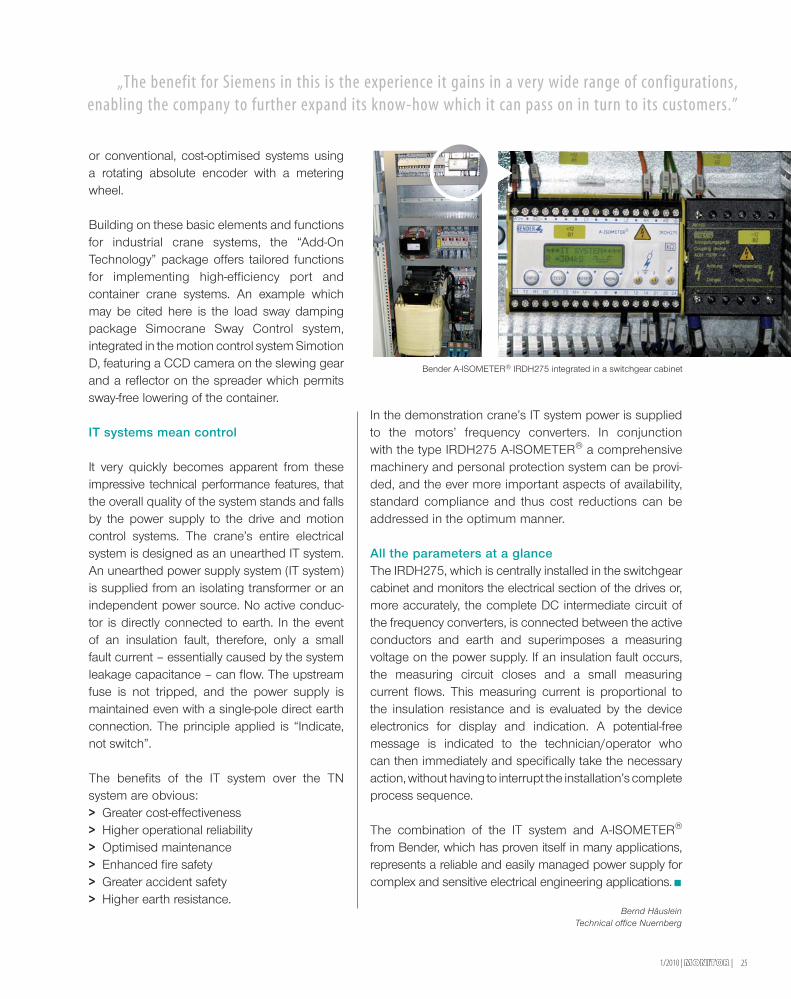
Bender A-ISOMETER® IRDH275 integrated in a switchgear cabinet
or conventional, cost-optimised systems usinga rotating absolute encoder with a meteringwheel.
Building on these basic elements and functionsfor industrial crane systems, the “Add-OnTechnology” package offers tailored functionsfor implementing high-efficiency port andcontainer crane systems. An example whichmay be cited here is the load sway dampingpackage Simocrane Sway Control system,integrated in the motion control system SimotionD, featuring a CCD camera on the slewing gearand a reflector on the spreader which permitssway-free lowering of the container.
IT systems mean control
It very quickly becomes apparent from theseimpressive technical performance features, thatthe overall quality of the system stands and fallsby the power supply to the drive and motioncontrol systems. The crane’s entire electricalsystem is designed as an unearthed IT system.An unearthed power supply system (IT system)is supplied from an isolating transformer or anindependent power source. No active conduc-tor is directly connected to earth. In the eventof an insulation fault, therefore, only a smallfault current – essentially caused by the systemleakage capacitance – can flow. The upstreamfuse is not tripped, and the power supply ismaintained even with a single-pole direct earthconnection. The principle applied is “Indicate,not switch”.
The benefits of the IT system over the TNsystem are obvious:> Greater cost-effectiveness> Higher operational reliability> Optimised maintenance> Enhanced fire safety> Greater accident safety> Higher earth resistance.
In the demonstration crane’s IT system power is suppliedto the motors’ frequency converters. In conjunctionwith the type IRDH275 A-ISOMETER® a comprehensivemachinery and personal protection system can be provi-ded, and the ever more important aspects of availability,standard compliance and thus cost reductions can beaddressed in the optimum manner.
All the parameters at a glanceThe IRDH275, which is centrally installed in the switchgearcabinet and monitors the electrical section of the drives or,more accurately, the complete DC intermediate circuit ofthe frequency converters, is connected between the activeconductors and earth and superimposes a measuringvoltage on the power supply. If an insulation fault occurs,the measuring circuit closes and a small measuringcurrent flows. This measuring current is proportional tothe insulation resistance and is evaluated by the deviceelectronics for display and indication. A potential-freemessage is indicated to the technician/operator whocan then immediately and specifically take the necessaryaction, without having to interrupt the installation’s completeprocess sequence.
The combination of the IT system and A-ISOMETER®
from Bender, which has proven itself in many applications,represents a reliable and easily managed power supply forcomplex and sensitive electrical engineering applications.
Bernd HäusleinTechnical office Nuernberg
26 | MONITORMONITOR | 1/2010
The GeckoLogic system house is part ofGeckoGroup AG, a regionally based yetglobally operating company which spe-cialises in the planning, assembly, in-stallation and maintenance of photovoltaicsystems.
>> GeckoLogic XXL GmbH’s particularrole within GeckoGroup AG is the plan-ning, implementation and managementof large-scale solar systems. With a totalinstalled output in excess of 18,000 kWp,the company can call on the pooled expe-rience of a successful corporate group.
With over 140 employees at six locationsin Germany, in-house module productionfacilities and over 3,500 completed PVsystems, GeckoGroup AG is one of theindustry’s major players. It has further loca-tions around the world, including branchesin the US and China. GeckoGroup AGuses its international network to make thelatest technologies available at any time toits customers throughout the world.
Why a gecko as a symbol?
GeckoLogic follows the logic of its animal symbol and embo-dies the qualities exhibited by geckos in its day-to-day businessoperations. Specifically:
> Best possible use of solar energy
> Optimum adaptation to the individual initial conditions
> A clear power of observation, agile actions and fast responsetimes.
Using roofs energetically
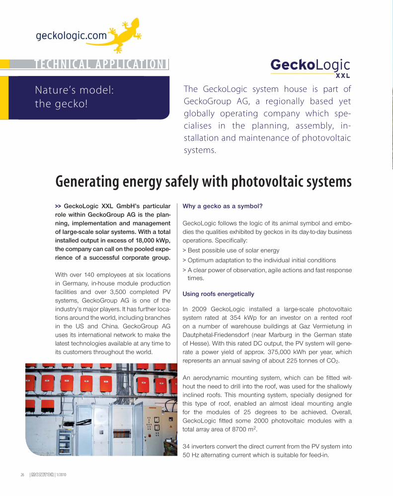
In 2009 GeckoLogic installed a large-scale photovoltaicsystem rated at 354 kWp for an investor on a rented roofon a number of warehouse buildings at Gaz Vermietung inDautphetal-Friedensdorf (near Marburg in the German stateof Hesse). With this rated DC output, the PV system will gene-rate a power yield of approx. 375,000 kWh per year, whichrepresents an annual saving of about 225 tonnes of CO2.
An aerodynamic mounting system, which can be fitted wit-hout the need to drill into the roof, was used for the shallowlyinclined roofs. This mounting system, specially designed forthis type of roof, enabled an almost ideal mounting anglefor the modules of 25 degrees to be achieved. Overall,GeckoLogic fitted some 2000 photovoltaic modules with atotal array area of 8700 m2.
34 inverters convert the direct current from the PV system into50 Hz alternating current which is suitable for feed-in.
TECHNICAL APPLICATION
Generating energy safely with photovoltaic systems
Nature’s model:the gecko!
1/2010 | MONITORMONITOR | 27
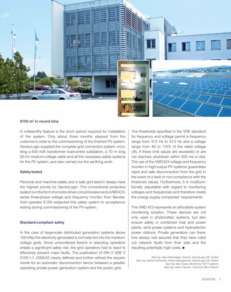
8700 m2 in record time
A noteworthy feature is the short period required for installationof the system. Only about three months elapsed from thecustomer’s order to the commissioning of the finished PV system.GeckoLogic supplied the complete grid connection system, inclu-ding a 630 kVA transformer load-centre substation, a 70 m long20 kV medium-voltage cable and all the necessary safety systemsfor the PV system, and also carried out the earthing work.
Safety-tested
Personal and machine safety and a safe grid feed-in always havethe highest priority for GeckoLogic. The conventional protectivesystemis in the formofamotor-drivencircuit-breakerandaVMD423-series three-phase voltage and frequency monitor from Bender.Grid operator E.ON subjected this safety system to acceptance-testing during commissioning of the PV system.
Standard-compliant safety
In the case of large-scale distributed generation systems above100 kWp the electricity generated is normally fed into the medium-voltage grids. Since unmonitored feed-in in islanding operationentails a significant safety risk, the grid operators had to react toeffectively prevent major faults. The publication of DIN V VDE V0126-1-1, 2006-02 clearly defined and further refined the require-ments for an automatic disconnection device between a parallel-operating private power generation system and the public grid.
The thresholds specified in the VDE standardfor frequency and voltage permit a frequencyrange from 47.5 Hz to 51.5 Hz and a voltagerange from 80 to 115% of the rated voltageUN. If these limit values are exceeded or arenot reached, shutdown within 200 ms is vital.The use of the VMD423 voltage and frequencymonitor in high-output PV systems guaranteesrapid and safe disconnection from the grid inthe event of a fault or non-compliance with thethreshold values. Furthermore, it is multifunc-tionally adjustable with regard to monitoringvoltages and frequencies and therefore meetsthe energy supply companies’ requirements.
The VMD 423 represents an affordable systemmonitoring solution. These devices are notonly used in photovoltaic systems, but alsoensure safety in combined heat and powerplants, wind power systems and hydroelectricpower stations. Private generators can there-fore always rest assured that they have ruledout network faults from their side and theresulting potentially high costs.
Dipl.-Ing. Gerd Oelschläger, Director, GeckoLogic XXL GmbHDipl.-Ing. Herbert Schneider, Project Management, GeckoLogic XXL GmbH
Dipl.-Ing. Marc Euker, Monitoring TN/TT systemsDipl.-Ing. Heiner Carnein, Technical office Hessen

The Italian Navy’s newest aircraft carrier, the “Cavour”, set sail inJanuary 2010 for its first operational mission. By contrast with itsmain function, this was for purely civilian purposes: to providerelief after the disaster in Haiti. Thanks to the on-board Bendertechnology, the crew can rely on a dependable power supply forthe medical equipment.
“Cavour” aids relief operation
| MONITORMONITOR | 1/201028
T E CHN I C A L APP L I C AT I ON
1/2010 | MONITORMONITOR | 29
T h e n e w e s t I t a l i a n a i r c r a f t c a r r i e r o n a i d d u t y i n H a i t i
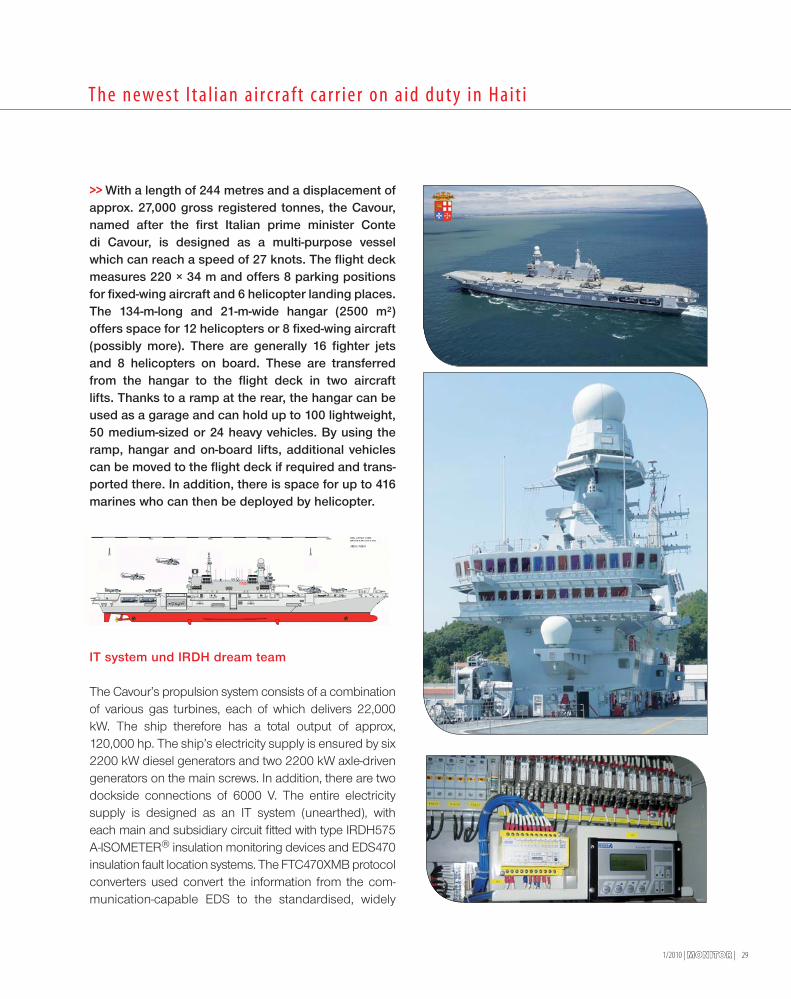
>> With a length of 244 metres and a displacement ofapprox. 27,000 gross registered tonnes, the Cavour,named after the first Italian prime minister Contedi Cavour, is designed as a multi-purpose vesselwhich can reach a speed of 27 knots. The flight deckmeasures 220 × 34 m and offers 8 parking positionsfor fixed-wing aircraft and 6 helicopter landing places.The 134-m-long and 21-m-wide hangar (2500 m²)offers space for 12 helicopters or 8 fixed-wing aircraft(possibly more). There are generally 16 fighter jetsand 8 helicopters on board. These are transferredfrom the hangar to the flight deck in two aircraftlifts. Thanks to a ramp at the rear, the hangar can beused as a garage and can hold up to 100 lightweight,50 medium-sized or 24 heavy vehicles. By using theramp, hangar and on-board lifts, additional vehiclescan be moved to the flight deck if required and trans-ported there. In addition, there is space for up to 416marines who can then be deployed by helicopter.
IT system und IRDH dream team
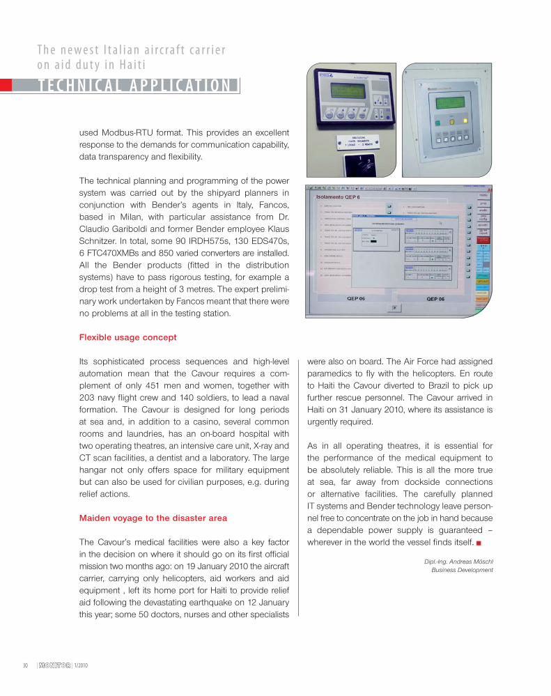
The Cavour’s propulsion system consists of a combinationof various gas turbines, each of which delivers 22,000kW. The ship therefore has a total output of approx,120,000 hp. The ship’s electricity supply is ensured by six2200 kW diesel generators and two 2200 kW axle-drivengenerators on the main screws. In addition, there are twodockside connections of 6000 V. The entire electricitysupply is designed as an IT system (unearthed), witheach main and subsidiary circuit fitted with type IRDH575A-ISOMETER® insulation monitoring devices and EDS470insulation fault location systems. The FTC470XMB protocolconverters used convert the information from the com-munication-capable EDS to the standardised, widely
| MONITORMONITOR | 1/201030
used Modbus-RTU format. This provides an excellentresponse to the demands for communication capability,data transparency and flexibility.
The technical planning and programming of the powersystem was carried out by the shipyard planners inconjunction with Bender’s agents in Italy, Fancos,based in Milan, with particular assistance from Dr.Claudio Gariboldi and former Bender employee KlausSchnitzer. In total, some 90 IRDH575s, 130 EDS470s,6 FTC470XMBs and 850 varied converters are installed.All the Bender products (fitted in the distributionsystems) have to pass rigorous testing, for example adrop test from a height of 3 metres. The expert prelimi-nary work undertaken by Fancos meant that there wereno problems at all in the testing station.
Flexible usage concept
Its sophisticated process sequences and high-levelautomation mean that the Cavour requires a com-plement of only 451 men and women, together with203 navy flight crew and 140 soldiers, to lead a navalformation. The Cavour is designed for long periodsat sea and, in addition to a casino, several commonrooms and laundries, has an on-board hospital withtwo operating theatres, an intensive care unit, X-ray andCT scan facilities, a dentist and a laboratory. The largehangar not only offers space for military equipmentbut can also be used for civilian purposes, e.g. duringrelief actions.
Maiden voyage to the disaster area
The Cavour’s medical facilities were also a key factorin the decision on where it should go on its first officialmission two months ago: on 19 January 2010 the aircraftcarrier, carrying only helicopters, aid workers and aidequipment , left its home port for Haiti to provide reliefaid following the devastating earthquake on 12 Januarythis year; some 50 doctors, nurses and other specialists
were also on board. The Air Force had assignedparamedics to fly with the helicopters. En routeto Haiti the Cavour diverted to Brazil to pick upfurther rescue personnel. The Cavour arrived inHaiti on 31 January 2010, where its assistance isurgently required.
As in all operating theatres, it is essential forthe performance of the medical equipment tobe absolutely reliable. This is all the more trueat sea, far away from dockside connectionsor alternative facilities. The carefully plannedIT systems and Bender technology leave person-nel free to concentrate on the job in hand becausea dependable power supply is guaranteed –wherever in the world the vessel finds itself.
Dipl.-Ing. Andreas MöschlBusiness Development
T h e n e w e s t I t a l i a n a i r c r a f t c a r r i e ro n a i d d u t y i n H a i t i
T E CHN I C A L APP L I C AT I ON
1/2010 | MONITORMONITOR | 31
From punch card to petabyte
C U S T OM E R P O R T R A I T
>> More than 9.5 million employeeshold one in their hands every month:a payroll slip generated by or with pro-ducts from IT service provider DATEVeG. DATEV also handles the financialaccounting systems for some two-thirds of the German companies, viathe internet too, in an increasing num-ber of cases. This makes the coopera-tively organised company one of thelargest IT service providers in Europe.
Nuremberg-based DATEVeG is the software houseand IT service provider fortax accountants, auditors
and lawyers, as well as their respectiveclients. Its range of services coversaccounting, personnel management,business consultancy, tax, enterpriseresource planning (ERP), office manage-ment and planning. DATEV was foundedin 1966 and is one of the largest infor-mation service providers and software
houses in Europe. With its cooperatively organised39,000 or so members and over 5500 employees itnow achieves a revenue of around 670 million euros.
DATEV’s service spectrum ranges from over 200 PCprograms via online applications, data processingand archiving in its computer centre, outsourcingand security services, to consultancy services andknowledge transfer in Germany and a few otherEuropean countries.
Credit and debit
The accounts of 2.5 million, mostly medium-sizedcompanies are prepared each month with theaid of DATEV software. Every month our in-houseprinting and mailing centre sends out some twomillion business reports. Of the more than 9.5 millionpayroll slips produced every month, more thanseven million come from the DATEV computerprinting and mailing centre, and an estimatedtwo million or so are generated using DATEV PCprograms by companies and firms themselveslocally.
DATEV eG
From a small cooperative to a heavyweight in the IT service sector
Central data hub
Information is exchanged largely automatically via the DATEVcomputer centre between medium-sized companies, theirtax accounts and some 200 institutions in Germany – inclu-ding tax offices, social insurance agencies, health insurancecompanies, banks, trade associations and statistical offices.Databases hold the full texts of around 480,000 documentson issues such as tax, civil, commercial and company lawfor consultation by DATEV members.
Service pillar
In addition to software development and its straightforwardfinancial and payroll accounting services, DATEV’s portfolioalso includes consultancy services. For example, DATEVprovides consultancy to lawyer’s firms and, in associationwith its members, also to companies on strategic, techni-cal and organisational issues. Furthermore, DATEV assistsauditors, particularly with solutions related to audits ofannual accounts. DATEV has been operating in the law firmmarket since 1998. The IT service provider is now no. 4among the relevant companies in Germany.
DATEV also promotes collaboration between tax accoun-tants and companies. A tailored splitting and meshing of thework processes, relating to accounting, for example, opensup the potential for synergies. The ideal software for imple-menting this jointly defined division of functions is providedby DATEV, ranging from aspects such as enterprise resourceand quality management to cost accounting and personnelmanagement. Local authorities are also making increasinguse of business management concepts – together withthe tax accountant DATEV provides consultancy tailoredspecifically to local authority interests and an integratedsoftware system for all financial aspects.
DATEV in Europe
DATEV eG in Nuremberg assists tax accountants, auditors,lawyers and their usually medium-sized business clientswith their cross-border operations. To provide the necessaryassistance, our cooperative has established a highly effectiveEuropean network – offering the same high service andquality standards which have been the trademark of thissoftware and IT service provider for more than four deca-des in Germany. The local subsidiaries are familiar with the
| MONITORMONITOR | 1/201032
CUSTOMER PORTRAIT
1/2010 | MONITORMONITOR | 33
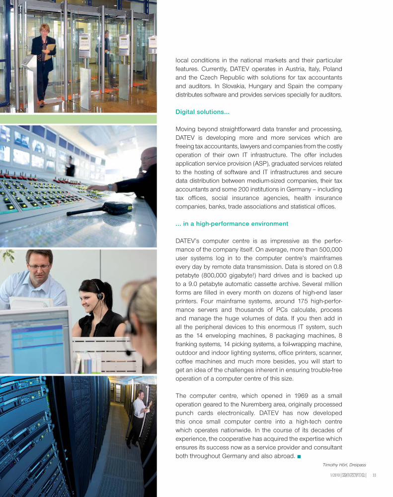
local conditions in the national markets and their particularfeatures. Currently, DATEV operates in Austria, Italy, Polandand the Czech Republic with solutions for tax accountantsand auditors. In Slovakia, Hungary and Spain the companydistributes software and provides services specially for auditors.
Digital solutions...
Moving beyond straightforward data transfer and processing,DATEV is developing more and more services which arefreeing tax accountants, lawyers and companies from the costlyoperation of their own IT infrastructure. The offer includesapplication service provision (ASP), graduated services relatedto the hosting of software and IT infrastructures and securedata distribution between medium-sized companies, their taxaccountants and some 200 institutions in Germany – includingtax offices, social insurance agencies, health insurancecompanies, banks, trade associations and statistical offices.
... in a high-performance environment
DATEV’s computer centre is as impressive as the perfor-mance of the company itself. On average, more than 500,000user systems log in to the computer centre’s mainframesevery day by remote data transmission. Data is stored on 0.8petabyte (800,000 gigabyte!) hard drives and is backed upto a 9.0 petabyte automatic cassette archive. Several millionforms are filled in every month on dozens of high-end laserprinters. Four mainframe systems, around 175 high-perfor-mance servers and thousands of PCs calculate, processand manage the huge volumes of data. If you then add inall the peripheral devices to this enormous IT system, suchas the 14 enveloping machines, 8 packaging machines, 8franking systems, 14 picking systems, a foil-wrapping machine,outdoor and indoor lighting systems, office printers, scanner,coffee machines and much more besides, you will start toget an idea of the challenges inherent in ensuring trouble-freeoperation of a computer centre of this size.
The computer centre, which opened in 1969 as a smalloperation geared to the Nuremberg area, originally processedpunch cards electronically. DATEV has now developedthis once small computer centre into a high-tech centrewhich operates nationwide. In the course of its decades ofexperience, the cooperative has acquired the expertise whichensures its success now as a service provider and consultantboth throughout Germany and also abroad.
Timothy Hörl, Dreipass
| MONITORMONITOR | 1/201034
>> Bender has been committed to automated production
processes since the 1990s. It all started in 1991 with an
automatic test system for high-voltage measurement of termi-
nals. Which modernisation methods in the company’s history
do you consider to be the decisive ones?
I can very clearly remember this occasion, especially as it was
the kick-off for a whole series of measures up to the present day.
Of capital importance and the most crucial milestones were the:
• Introduction of the SMD production technology with presentlytwo high-speed assembly lines with integrated AutomaticOptical Inspection Systems (AOI)
• Automatic final inspection of the major Bender devices
• Use of laser technology for labelling of devices
• Development of a high-performance Production PlanningSystem (PPS)
• Restructuring of the entire production process and material
management system in compliance with the EU RoHS directive
• In-circuit testing of electronic assemblies
• Dispenser process in SMD production
• Electro static discharge (ESD) protection in production andmaterial management
• Automation of an inline depaneling system
• Use of intelligent storage of components (lean-lift-principle).
Production processes are always in the stress field between
performance, costs and – naturally – customer specifications. How
do you attempt to achieve homogeneity in this stress field?
Leaving aside the general electrical engineering definition, there is
an apposite physical definition for a stress field: The force in a body
that ensures that its form remains stable. By “force” I mean lean and
efficient processes in the organisation, low inventories at the same time
with short processing times and constantly developing new processes.
That’s how I achieve a state as stable as possible, or homogeneity
within this stress field.
The quality of Bender products is almost legendary. Which quality
assurance measures during manufacture contribute to this high
quality production?
Quality in a company is a very complex and demanding issue which
involves every department. You can’t simply switch a button and say:
From now on we are producing quality. It simply doesn’t work like that.
It is of absolutely vital, fundamental importance to know how good
or bad, for example, a production process is or the performance of
a supplier or the finish of a component. First you have to provide the
necessary comprehensive transparency and from it derive the specific
appropriate actions. With this in mind, we have now systematically
created information platforms and monitoring systems in order to
continuously identify and communicate potential improvements.
Head of Production and Logisticsof the Dipl.-Ing. W. BENDER GmbH & Co. KG
I N T E R V I E W
DIPL.-ING. MANFRED NICKLAS
PROFESSIONAL DEVELOPMENT
1975 – 1979 Academic studies at the Technical College in Giessen.Course of studies: Electrical Telecommunication Engineering/High-Frequency Engineering
1979 – 1980 Project collaboration with the Federal Agencyfor Air-Traffic Control in Frankfurt
1980 – 1984 Project planning of installations and project leadership– Europe RMG, Kassel/Butzbach
1981 – 1990 Head of Service and Commissioning – Europe RMG, Butzbach
1990 – 1994 Head of Prototyping and Process Qualification, Bender, Gruenberg
Since 1994 Head of Production and Logistics, Bender, Gruenberg
with Dipl.-Ing. Manfred Nicklas
35
The Production Information System (PIS) for troubleshooting for the
fi rst time provided the means for realtime recording and channelling of
all the relevant production occurrences. This information is promptly
available to the appropriate decision-makers, who can traceably
initiate the necessary actions.
The introduction of the Electronic Inspection Chart entailed the
installation of fault-detection sensors along the entire production
chain. This allows to either observe live the quality status of a
process stage or to generate automatic messages to the process
owners when set quality criteria are exceeded to make immediate
intervention possible. Furthermore, the collected data is statistically
evaluated and communicated and used for quality assessment.
A system for recording supplier performance regarding delivery
reliability and delivery quality constantly provides data to a central
evaluation unit. This evaluation results in the supplier assessment
and the instigation of measures in the case of non-compliance with
specifi ed standards.
With the application of a Traceability System we are able to precisely
trace back to its origin each component in a Bender device. This
means we know who supplied the relevant component and when,
where and on which machines it was installed and who was
involved in the production process.
An effective controlling system for meeting deadlines of our
production orders guarantees the instigation of corrective action to
achieve the rerquired deadline corridor.
And last but not least a key tool. Two years ago we successfully
implemented the Continuous Improvement Process (CIP) throug-
hout the production and logistics operations. This constantly
reviews the human experience in the work process to look for
possible improvements which come, as it is, from the prime informa-
tion source.
Basking in your successes is probably never a good idea in any
sector and technological leadership is always a snapshot. How
can Bender adapt to the future? Do you adopt modern manage-
ment concepts?
The competitive environment has changed noticeably and this
applies to Bender as well. The challenges have increased for us too,
and will continue to do so. Against such a backdrop a company has
to at least scrutinise existing management models, irrespective of
the extent to which it is affected by the current economic crisis. A
move is emerging which seems to be both very interesting and
exciting: The golden opportunity of a company are its people!
Nurturing and further developing the hidden potential of the
workforce are the pillars of a modern management system.
Talking about lean production: What precise form does the
implementation of this theory take at Bender? Can you give
a descriptive example?
You’ve hit on a subject which is really close to my heart.
Happily, more and more successful companies in Germany
and elsewhere in Europe are taking up these lean
elements. These models have now also reached our Technical
Universities and are being taught and researched!
However, not every company really succeeds in implementing
the theory, since it is about the interaction of the individual
methods. Lean elements always consist of both a visible
element and an invisible element, but it is the latter that is
particularly important.
The visible aspects in our company include manufacturing
cells, CIP/kaizen activities, visualisation methods, certain
machine features and material-supply principles. The invisible,
but nonetheless present elements are: standardisation with
PDCA, Lean Thinking, Shop Floor, leading with targets. For
two years we are successfully working and experimenting with
these tools in selected areas.
All theoretical production organisation models now empha-
sise that the “employee” factor has to be seen as an
integral element of process optimisations. To what extent
does Bender take the so called “human capital” into
account?
You can buy machines and implement new processes.
However, it is not possible to buy the knowledge and the
experience of your employees! Yet this is possibly a company’s
greatest potential!
The knowledge in a company as an intangible asset is based
solely on the employee’s individual experience with the
company. As a basic principle this is always placed at the
outset of each important optimisation project.
Mr Nicklas, thank you for talking to us.
Timothy Hörl, Dreipass
1/2010 | MONITORMONITOR |

Dipl.-Ing. W. Bender GmbH & Co. KG
Londorfer Str. 65
35305 Gruenberg / Germany
Fon: +49 6401 807-0
Fax: +49 6401 807-259
E-mail: [email protected]
www.bender-de.com
The Bender Group with its main offi ce
in Gruenberg/Hesse has 56 agencies with
over 500 employees worldwide.
Worldwide forElectrical Safety