madymo human body models manual release 7.7 june...
TRANSCRIPT
i
MADYMO
Human Body Models Manual
Release 7.7
June 2017
© Copyright 2017 by TASS International BV All rights reserved.
MADYMO® has been developed at TASS International BV.
This document contains proprietary and confidential information of TASS International BV.
The contents of this document may not be disclosed to third parties, copied, or duplicated in
any form, in whole or in part, without the prior permission of TASS International BV.
The terms and conditions governing the licensing of MADYMO® software consists solely of
those set forth in written contracts between TASS International BV or TASS International BV-authorised third parties and its customers. The software may only be used or copied in
accordance with the terms of these contracts.


MADYMO Human Models Manual Release 7.7
3
Table of contents
Table of contents ....................................................................................................... 3
1 Introduction ....................................................................................................... 5 1.1 General human body model description .................................................... 6
1.1.1 Model types ................................................................................. 6 1.1.2 Facet occupant models ................................................................. 7 1.1.3 Facet active human model............................................................ 8 1.1.4 Facet pedestrian model ................................................................ 8 1.1.5 Ellipsoid pedestrian models ......................................................... 8 1.1.6 Available human models.............................................................. 8
1.2 Model validation ...................................................................................... 9 1.3 User instructions .................................................................................... 10
1.3.1 Human model files .................................................................... 10 1.3.2 Integration method and time step ............................................... 11 1.3.3 Human model positioning .......................................................... 11 1.3.4 Contacts .................................................................................... 12 1.3.5 Output ....................................................................................... 12
1.4 Examples ............................................................................................... 13 1.5 Required model licenses ......................................................................... 13
2 Facet occupant models ..................................................................................... 15 2.1 Model description................................................................................... 16
2.1.1 Anthropometry .......................................................................... 17 2.1.2 Configuration ............................................................................ 19 2.1.3 Spine and neck .......................................................................... 20 2.1.4 Thorax and abdomen ................................................................. 21 2.1.5 Pelvis ........................................................................................ 23 2.1.6 Shoulders .................................................................................. 23 2.1.7 Limbs ........................................................................................ 24 2.1.8 Skin ........................................................................................... 25
2.2 Model validation .................................................................................... 25 2.2.1 Blunt impact tests ...................................................................... 25 2.2.2 Sled tests ................................................................................... 27 2.2.3 Vertical vibration ....................................................................... 28 2.2.4 Child model validation .............................................................. 29
2.3 User instructions .................................................................................... 30 2.3.1 Integration method and time step ............................................... 30 2.3.2 Positioning ................................................................................ 30 2.3.3 Contacts .................................................................................... 38

MADYMO Human Models Manual Release 7.7
4
2.3.4 FE belt positioning and contact definition .................................. 39 2.3.5 Output ....................................................................................... 39
2.4 Examples ............................................................................................... 44 2.4.1 Frontal impact with a belt .......................................................... 44 2.4.2 Occupant model positioning method b ....................................... 44
3 Facet active human model ................................................................................ 45
4 Facet pedestrian model ..................................................................................... 46 4.1 Model description .................................................................................. 47 4.2 Model validation .................................................................................... 47 4.3 User instructions .................................................................................... 47
4.3.1 Integration method and time step ............................................... 47 4.3.2 Positioning ................................................................................ 47 4.3.3 Contacts .................................................................................... 51 4.3.4 Output ....................................................................................... 52
5 Ellipsoid pedestrian models .............................................................................. 58 5.1 Model description .................................................................................. 59
5.1.1 Anthropometry .......................................................................... 59 5.1.2 Configuration ............................................................................ 60 5.1.3 Spine and neck .......................................................................... 61 5.1.4 Thorax and abdomen ................................................................. 61 5.1.5 Hip ............................................................................................ 61 5.1.6 Knee ......................................................................................... 62 5.1.7 Upper and lower leg .................................................................. 62 5.1.8 Ankle, foot and shoe .................................................................. 65
5.2 Model validation .................................................................................... 66 5.2.1 Blunt impact tests ...................................................................... 66 5.2.2 Car-pedestrian tests ................................................................... 68
5.3 User instructions .................................................................................... 68 5.3.1 Integration method and time step ............................................... 68 5.3.2 Positioning ................................................................................ 69 5.3.3 Contacts .................................................................................... 72 5.3.4 Output ....................................................................................... 73
5.4 Example ................................................................................................. 77 5.4.1 Car-pedestrian impact ................................................................ 77
6 References ....................................................................................................... 79
MADYMO Human Models Manual Release 7.7
5
1 Introduction
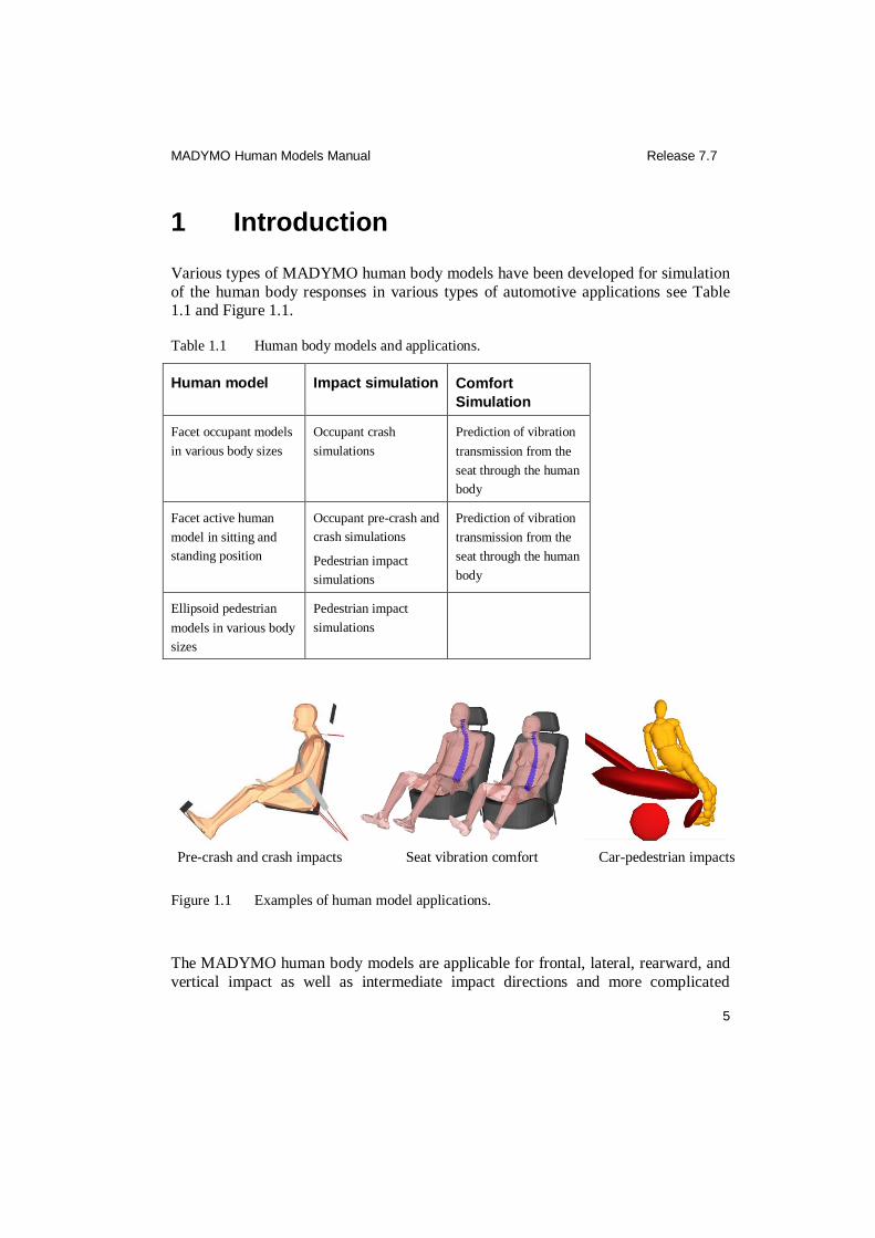
Various types of MADYMO human body models have been developed for simulation
of the human body responses in various types of automotive applications see Table 1.1 and Figure 1.1.
Table 1.1 Human body models and applications.
Human model Impact simulation Comfort
Simulation
Facet occupant models
in various body sizes
Occupant crash
simulations
Prediction of vibration
transmission from the
seat through the human
body
Facet active human
model in sitting and
standing position
Occupant pre-crash and
crash simulations
Pedestrian impact
simulations
Prediction of vibration
transmission from the
seat through the human
body
Ellipsoid pedestrian
models in various body
sizes
Pedestrian impact
simulations
Pre-crash and crash impacts Seat vibration comfort Car-pedestrian impacts
Figure 1.1 Examples of human model applications.
The MADYMO human body models are applicable for frontal, lateral, rearward, and
vertical impact as well as intermediate impact directions and more complicated

MADYMO Human Models Manual Release 7.7
6
scenarios like rollover. Consequently, they are more biofidelic than dummy models, which are developed for a particular loading direction. Dummy models are mostly
used for simulations of standard (regulated) impact tests. The MADYMO human
models were developed for the evaluation and optimisation of passive and active restraint systems in a wider range of loading conditions than the standard impact tests.
The benefits of using human body models are:
Improved biofidelity compared to dummy models
Multi-directional
Scaleable to other body sizes
Biomechanical data can be easily incorporated
Modelling of post-failure (e.g. fracture) response
Inclusion of muscle activity
Inclusion of controlled posture maintenance
1.1 General human body model description
In this section, general features of the different types of MADYMO human body models are described. Also, information is given on what models are currently
available together with general guidelines on how to use these models. Specific
features and guidelines for using the facet occupant models, the facet active occupant model, and the ellipsoid pedestrian models are described in Chapters 2, 3, and 5,
respectively.
1.1.1 Model types
The types of MADYMO human models that have been released with MADYMO v7.7 are:
1. Facet occupant models
2. Facet active human model
3. Facet pedestrian model
4. Ellipsoid pedestrian models

MADYMO Human Models Manual Release 7.7
7
The skeleton of these human models mainly consists of chains of rigid bodies connected by kinematic joints. The inertia properties of the rigid bodies and the
ranges of motion of the kinematic joints have been based on biomechanical data
published in literature. Joint, cardan, point and six-dof restraint models are used to model the static and dynamic joint characteristics. The joint characteristics and
mechanical properties of the various segments of the human models are based on
biomechanical data from literature and have been tuned and validated using volunteer
and post mortem human subject (PMHS) responses in various impact tests. The geometry, inertial and mechanical properties of the human model segments depend on
the type of model and its size.
The different human models use different outer geometry definitions. The occupant models and the sitting active human model have been designed for accurate contact
interaction of the skin with the vehicle interior. Therefore, the outer geometry of the
occupant models is represented by facets. For pedestrian applications two different model types are available. The ellipsoid models are fast, robust and easy to scale to
other body dimensions. These models can be used for more conceptual analysis,
preferably with an MB vehicle. For interaction with an FE vehicle, it is recommended
to use the facet pedestrian model as it has a facet geometry which allows for more robust contact interaction with an FE environment.
1.1.2 Facet occupant models
The facet occupant models are developed and validated for impact simulation and for simulation of vibration transmission as related to seating comfort. The outer surface
of the facet occupant models is described with meshes of shell-type massless contact
elements (further referred to as facet surfaces). These facet surfaces are fully
connected to rigid and/or flexible bodies. They allow a more accurate geometric representation compared to ellipsoids. Although the facet surfaces are defined by FE
elements, the facet occupant models are still multi-body models, since no FE solver is
used in simulations. Inertial properties of the occupant segments are represented fully by the inertial properties of the rigid and flexible bodies in the facet occupant model.
Deformation of soft tissues (flesh and skin) is represented by stress-based contact
characteristics defined for the facet surfaces. Using these contact characteristics in contact definitions, soft tissue deformation is described accurately through the contact
interactions of the facet occupant model with itself and with its environment.
Structural deformation of the thoracic and abdominal area is modelled using flexible
bodies (MADYMO Theory Manual, Koppens 1988). The specific features and guidelines of the facet occupant models are described in Chapter 2.
MADYMO Human Models Manual Release 7.7
8
1.1.3 Facet active human model
The facet active human model is developed and validated for pre-crash simulation,
occupant and pedestrian impact simulation and for simulation of vibration
transmission as related to seating comfort. Compared to the facet occupant model, the neck, arms and lower extremities are modelled in more detail as well as active
behaviour to keep the initial position of the neck, spine, hips and elbows are
modelled. Besides occupant crash conditions (frontal, rear, side and vertical), the
model is suitable for pedestrian impact and low severity loading like pre-crash braking. The outer surface of the active human model is represented by facets similar
to that of the facet occupant model. The active human model is available in two
versions, a sitting model and a standing model. The specific features and guidelines of the facet active human model are described in the MADYMO Model Manual.
1.1.4 Facet pedestrian model
The facet pedestrian mode is identical to the standing facet active human model, except that it does not include active behaviour. This model can be used for
pedestrian impact simulations with an FE vehicle model, and is described in Chapter
4.
1.1.5 Ellipsoid pedestrian models
The outer geometry of the ellipsoid pedestrian models is represented by ellipsoids,
which provide a less accurate representation of the geometry but result in shorter
computation times than facets. The inertial properties of the pedestrian segments are incorporated in the rigid bodies of the pedestrian models. In the ellipsoid pedestrian
models, structural deformation of flexible components is lumped in kinematic joints
in combination with dynamic restraint models. This approach was applied in order to
simulate elastic long bone bending as well as fracture in femur and tibia. Deformation of soft tissues (flesh and skin) is represented by force-penetration based contact
characteristics for the ellipsoids. These characteristics are used to describe contact
interactions of the pedestrian model with itself and with its environment. Inertial properties of the pedestrian components are defined in the rigid bodies. The specific
features and guidelines of the pedestrian models are described in Chapter 5.
1.1.6 Available human models
The available occupant, active and pedestrian models are given in Table 1.2, Table
1.3 and Table 1.4 respectively. The human model files can be found in the directory
$MADHOME/share/dbs/human/3d.

MADYMO Human Models Manual Release 7.7
9
Table 1.2 Occupant models.
Model name File name Version
Facet small female occupant h_occ05fc 3.4
Facet mid-size-male occupant h_occ50fc 5.2
Facet large male occupant h_occ95fc 1.8
Facet 1.5-year-old child occupant h_occ1_5yfc 1.6
Facet 3-year-old child occupant h_occ3yfc 1.6
Facet 6-year-old child occupant h_occ6yfc 2.3
Facet 10-year-old child occupant h_occ10yfc 1.6
Scalable facet mid-size male occupant h_occ50fc.par 4.11
Scalable facet small female occupant h_occ05fc.par 2.12
Table 1.3 Active human models.
Model name File name Version
Facet mid-size male active human model in sitting position
h_act50fc_sitting 2.0
Facet mid-size male active human model in standing position
h_act50fc_standing 2.0
Table 1.4 Pedestrian models.
Model name File name Version
Facet mid-size male pedestrian h_ped50fc 3.0
Ellipsoid 3-year-old child pedestrian h_ped3yel 5.1
Ellipsoid 6-year-old child pedestrian h_ped6yel 5.1
Ellipsoid small female pedestrian h_ped05el 5.1
Ellipsoid mid-size male pedestrian h_ped50el 5.1
Ellipsoid large male pedestrian h_ped95el 5.1
Ellipsoid scalable mid-size-male pedestrian h_ped50el.par 5.1
1.2 Model validation
Much effort has gone into into validating the MADYMO human body models for a wide range of loading conditions. The human models have been validated extensively
MADYMO Human Models Manual Release 7.7
10
on segment as well as full body level with volunteer (low to mid severity impact) as well as PMHS test data (mid to high severity impact). For segment validation static as
well as dynamic tests have been used for full body only dynamic tests. Model
parameters that have a wide range in the literature and model parameters that could not be found in the literature have been tuned with these validation tests. A review of
segment impact and full body impact test data used for model validation is given for
each type of human model in the corresponding chapter.
1.3 User instructions
The ‘user instructions’ sections of the corresponding chapters in this manual describe how to handle the human models model-specific. In this section, information is given
to guide users through implementing human models in their own applications.
1.3.1 Human model files
Like the MADYMO dummy models, each MADYMO human model is supplied in
two files: a user-file (<filename>_usr.xml) and an include-file (<filename>_inc.xml).
The user-file contains the human model system, in which the user-interactive human
model elements are defined and the include-file is called. The user-interactive elements are those model elements that may need modification when applying the
human model. Besides the human model system, the user-file contains the required
control elements and a reference space system. This makes it a complete MADYMO input deck containing the human model defined in its standard position. The user can
implement more systems, system interactions (contact definitions between different
system), loads applied to whole systems etc. in the user-file to complete the model for a particular application.
The include-file contains the human model itself, including features like pre-defined
contact of the human model with itself. It is strongly advised not to modify any
parameters in the include-file, since this may affect the performance of the human model. It is also recommended not to modify the BELT elements that are defined in
the facet occupant human model user-files, since these are part of these models. (For
user- and include-file architecture see also MADYMO Model Manual.)
The human models can be applied in two ways:
1. by building an ‘environment’ model around the human model in the user-file,
2. by including the human model system (the SYSTEM.MODEL element in the
user-file), accessory belts and functions in an existing ‘environment’ model input deck.

MADYMO Human Models Manual Release 7.7
11
When calling human model output signals, or defining loads on and (contact) interactions with the human model, reference must be made to the human model
system. This can be done by referring either to the system ID or the system NAME.
For the facet occupant and the pedestrian models, a human model can be included more than once in an application, by making the system IDs and NAMEs unique (no
reference is made to ID or NAME inside these a human models). For the active
human model the system model has to be kept at 99, and thus only one active human
model can be used in a application. Note that the DEFINE elements used for some human models can be included only once and hence will be identical in each human
model present in one simulation.
1.3.2 Integration method and time step
Each human model has a recommended integration method and minimum integration
time step for which it is validated and tested. The integration method and time step
are defined for each human model in the CONTROL.ANALYSIS_TIME element in the user-file. They are also given in the ‘user instructions’ section of the
corresponding chapter in this manual.
Note that the contact stiffnesses of the modelled environment mainly determine the
time step needed, thus stiffer contacts or contact interactions with high damping might need smaller time steps than the recommended time step of the human model.
1.3.3 Human model positioning
In order to position the human model, the INITIAL.JOINT_POS elements have to be used. All joints that are needed for positioning the human model are defined in the
INITIAL.JOINT_POS elements in the human model user-file. Positions of all other
joints are defined in the human model include-file, and these should not be edited by
the user.
For joints of type FREE and SPHERICAL the rotational degrees of freedom should
be defined either using the R1, R2 and R3 attributes in INITIAL.JOINT_POS, or in
the related ORIENTATION elements. The defined elements use the successive rotation method. Joints can be locked in the INITIAL.JOINT_STATUS elements.
A human model is by default positioned relative to the (global) reference space co-
ordinate system. However, the human model can be positioned relative to a body of another system. This can be done in the human attachment element
CRDSYS_OBJECT named ‘Human_Attachment’ and the associated orientation
‘Human_Attachment_ori’ in that element. The human attachment element
‘Human_Attachment’ is comparable to the dummy attachment element 'Dummy_attachment' in a dummy model, which is located at the H-point.
MADYMO Human Models Manual Release 7.7
12
All joints needed for human model positioning are listed in the human model positioning tables in the ‘user instructions’ section of the following chapters. In these
tables all rotations are referred to with the terms pitch, roll and yaw (see Figure 2.7,
Error! Reference source not found. and Figure 5.4). The directions given in the tables refer to positive translation and rotation directions. For all joints, the directions
are defined with respect to their co-ordinate system orientation, when the human
model is in its reference position.
The various human models each require a different positioning technique. These techniques are explained in the ‘user instructions’ section of the corresponding
chapters.
1.3.4 Contacts
All contacts with the human model itself are already included in the model include-
file. The user has to define the external contact interactions between the human model
and its environment. To facilitate this, the human models have pre-defined contact groups that can be used directly in the external contact interactions. These pre-defined
contact groups are available for all relevant human model components. Note that
these contact groups do not necessarily include all ellipsoids/elements/nodes of the
components, but are defined such that the relevant outer surface is covered. Model specific information on these contact groups is given in tables in the corresponding
chapters. It is recommended to define contact only if it is really needed, in order to
avoid an unnecessary increase in calculation time. As a start for a simulation, the most proper way is to define contact only where it is expected. Thereafter, the contact
assumptions should be checked, and necessary corrections and/or refinements can be
made. Some general guidelines for contact definitions can be found in the MADYMO
Theory Manual and the MADYMO Reference Manual.
1.3.5 Output
The most relevant output signals and injury criteria are predefined in the human
model include-file. All output signals are defined corresponding to the orientation of the body. Output signals are as far as possible filtered according to the SAE J211/1
sign convention. In order to avoid problems with filtering of output signals, it is
recommended to use an output time step of at least 1.0E-04 s (TIME_STEP under CONTROL_OUTPUT).
Output of the human model is called in the user-file. This is done in the
TIME_HISTORY.MB element inside the CONTROL.OUTPUT element. The user
can place these names in the elements inside the TIME_HISTORY.MB element in order to obtain these output signals.

MADYMO Human Models Manual Release 7.7
13
To obtain injury criteria output, all the output signals that are used for that criterion, must be called in the CONTROL_OUTPUT element. Model specific information on
the output signals and injury criteria is given in the tables in the ‘user instructions’
section in the corresponding chapter.
1.4 Examples
For each type of human model, one or more examples of an (validation) application are described in this manual. An overview of the available example application files
of the non-active human models is given in Table 1.5.
Table 1.5 Example application files.
Application model File name Version
Positioning of the facet mid-size male occupant model, method b
e_occ50fc_pos_b 1) 1.4.2
Frontal impact of the facet mid-size male occupant model
e_occ50fc_imp 1) 1.6
Lateral impact of the mid-size male pedestrian model
e_ped50el 1) 1.3
1) Available in the directory $MADHOME/share/appl/3d.
1.5 Required model licenses
Table 1.6 lists the required license module name for each of the MADYMO Human
models. The listed modules are in additions to the MADYMO /Solver Multibody and MADYMO/CPU licenses that are always required to run MADYMO models.
Ellipsoid and facet models do not require a MADYMO /Solver FEM license. Scalable
models will need a SCALER license in order to generate a scaled version of the model.
Table 1.6 Human body models and required licenses.
Human Body model name License
Facet 1.5-year-old child occupant MADYMO/ Human Models/ Full Body Child
Facet 3-year-old child occupant MADYMO/ Human Models/ Full Body Child
Facet 6-year-old child occupant MADYMO/ Human Models/ Full Body Child
Facet 10-year-old child occupant MADYMO/ Human Models/ Full Body Child
Facet small female occupant MADYMO/ Human Models

MADYMO Human Models Manual Release 7.7
14
Facet mid-size male occupant MADYMO/ Human Models
Facet large male occupant MADYMO/ Human Models
Scalable facet mid-size male occupant MADYMO/ Human Models
Scalable facet small female occupant MADYMO/ Human Models
Facet active human model MADYMO/ HumanActive
Facet mid-size male pedestrian MADYMO/ Human Models/ Pedestrian
Ellipsoid 3-year-old child pedestrian MADYMO/ Human Models/ Pedestrian
Ellipsoid 6-year-old child pedestrian MADYMO/ Human Models/ Pedestrian
Ellipsoid small female pedestrian MADYMO/ Human Models/ Pedestrian
Ellipsoid mid-size male pedestrian MADYMO/ Human Models/ Pedestrian
Ellipsoid large male pedestrian MADYMO/ Human Models/ Pedestrian
Scalable ellipsoid mid-size male pedestrian MADYMO/ Human Models/ Pedestrian
MADYMO Human Models Manual Release 7.7
15
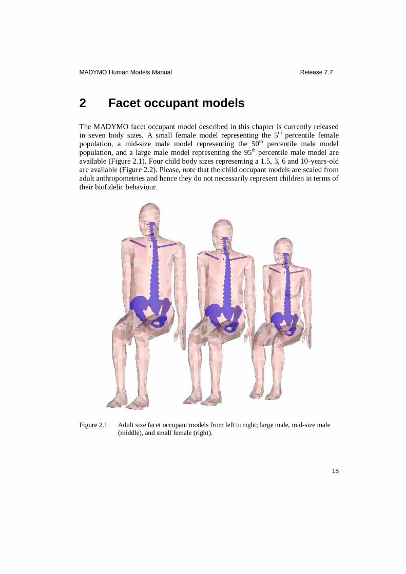
2 Facet occupant models
The MADYMO facet occupant model described in this chapter is currently released
in seven body sizes. A small female model representing the 5th
percentile female population, a mid-size male model representing the 50
th percentile male model
population, and a large male model representing the 95th percentile male model are
available (Figure 2.1). Four child body sizes representing a 1.5, 3, 6 and 10-years-old are available (Figure 2.2). Please, note that the child occupant models are scaled from
adult anthropometries and hence they do not necessarily represent children in terms of
their biofidelic behaviour.
Figure 2.1 Adult size facet occupant models from left to right; large male, mid-size male
(middle), and small female (right).

MADYMO Human Models Manual Release 7.7
16
Figure 2.2 Child facet occupant models from left to right; 1.5, 3, 6 and 10-year-old.
2.1 Model description
The MADYMO model names and input file names of the facet small female occupant
model, the facet mid-size male occupant model and the large male facet occupant model are:
Facet small female occupant: h_occ05fc_usr.xml
h_occ05fc_inc.xml
Facet mid-size male occupant: h_occ50fc_usr.xml h_occ50fc_inc.xml
Large male facet occupant: h_occ95fc_usr.xml
h_occ95fc_inc.xml
The MADYMO model names and input file names of the child occupant models are:
1.5-year-old child: h_occ1_5yfc_usr.xml
h_occ1_5y fc_inc.xml

MADYMO Human Models Manual Release 7.7
17
3-year-old child: h_occ3yfc_usr.xml h_occ3y fc_inc.xml
6-year-old child: h_occ6yfc_usr.xml
h_occ6y fc_inc.xml
10-year-old child: h_occ10yfc_usr.xml
h_occ10y fc_inc.xml
Besides these models, a scaleable facet male and female human occupant model are
available:
Parameter model mid size male: h_occ50fc.par
Parameter model small female: h_occ05fc.par
Using the MADYMO/SCALER utility, these models can be scaled towards different anthropometry data sets. It is recommended, to use the male model to create male and
child models and to use the female model to create adult or teenage female models.
A target model anthropometry can be created either by defining an anthropometry data set of 35 values, by defining 14 x 4 fixed scale factors or by using the GEBOD
database. Additional to the geometric properties, the following mechanical properties
are also scaled towards the target anthropometry: mass, inertia, stiffness and contact
characteristics. Several anthropometrically extreme models, ranging from small children to large adults, have been created using the 3 possible methods. The
definition of the anthropometry values and the fixed scaling factors produced
acceptable scaled models, whereas the GEBOD database sometimes generated models with unacceptable deviations, especially when scaling towards children.
The main limitation of the scalable models is that no age based material dependency
is taken into account during the scaling. As a result, the response of the child models
is not completely biofidelic. Furthermore, the impact behaviour (injuries, range of motion, etc.) of all models other than the base model has not yet been validated.
2.1.1 Anthropometry
2.1.1.1 Adults
The anthropometry of the adult facet occupant models has been obtained from the
database of the RAMSIS software package (RAMSIS 1997). The Western European
population aged 18 to 70 years of 1984 was used. For the facet mid-size male occupant model simply medium typologies were selected for height, weight and
MADYMO Human Models Manual Release 7.7
18
sitting height. For the small female a very short and very slim model was selected in RAMSIS. The resulting body mass and sitting height were considered to be somewhat
extreme also in comparison to the small female Hybrid III crash dummy. This was
resolved in a second step using the BODYBUILDER submodule of RAMSIS. The proportion and corpulence have been adapted by modification of the percentile values
of their related key parameters, respectively sitting height and waist circumference.
For the sitting height the percentile value was changed from 2.2% to 5.0%, the waist
circumference changed from 14.9% to 18.0%. The same procedure was followed to create the large male occupant model. In the first step a very tall subject with a large
waist was selected in RAMSIS, however the resulting body mass was somewhat high
and the standing height and sitting height were considered too low. Therefore, the BODYBUILDER module was used in a second step with the standing height, the
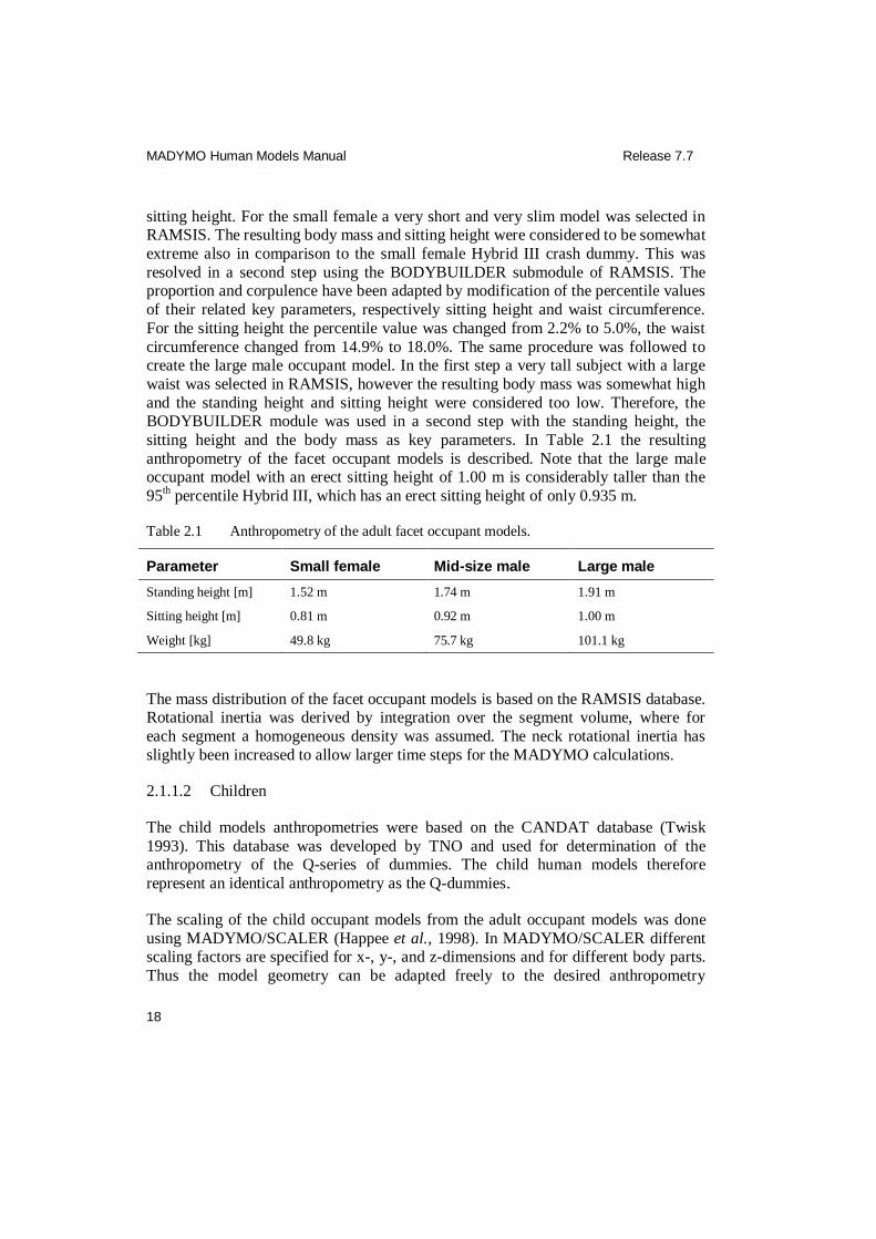
sitting height and the body mass as key parameters. In Table 2.1 the resulting
anthropometry of the facet occupant models is described. Note that the large male occupant model with an erect sitting height of 1.00 m is considerably taller than the
95th percentile Hybrid III, which has an erect sitting height of only 0.935 m.
Table 2.1 Anthropometry of the adult facet occupant models.
Parameter Small female Mid-size male Large male
Standing height [m] 1.52 m 1.74 m 1.91 m
Sitting height [m] 0.81 m 0.92 m 1.00 m
Weight [kg] 49.8 kg 75.7 kg 101.1 kg
The mass distribution of the facet occupant models is based on the RAMSIS database. Rotational inertia was derived by integration over the segment volume, where for
each segment a homogeneous density was assumed. The neck rotational inertia has
slightly been increased to allow larger time steps for the MADYMO calculations.
2.1.1.2 Children
The child models anthropometries were based on the CANDAT database (Twisk
1993). This database was developed by TNO and used for determination of the anthropometry of the Q-series of dummies. The child human models therefore
represent an identical anthropometry as the Q-dummies.
The scaling of the child occupant models from the adult occupant models was done
using MADYMO/SCALER (Happee et al., 1998). In MADYMO/SCALER different scaling factors are specified for x-, y-, and z-dimensions and for different body parts.
Thus the model geometry can be adapted freely to the desired anthropometry

MADYMO Human Models Manual Release 7.7
19
parameters. In addition to the geometry, all other model parameters can be scaled. Based on the desired anthropometry parameters there is scaling of:
Geometry
Mass and moments of Inertia
Joint characteristics (stiffness, friction, damping and hysteresis), including that of
protected joints
Ellipsoids and penetration characteristics
Force models
Fracture levels
Sensor locations
Besides these properties, the child occupant models are identical to the adult occupant models. The differences exisiting in material properties between tissues of adults and
children, as well as developmental stages of development of various organs have not
been taken into account in the current models. The anthropometry of the child
models, obtained with scaling is shown in Table 2.3.
Table 2.3 Anthropometry of the facet child occupant models.
Parameter 1.5-year-old 3-year-old 6-year-old 10-year-old
Standing height [m] 0.81 0.95 1.16 1.44
Sitting height [m] 0.50 0.55 0.63 0.75
Weight [kg] 11.0 kg 14.5 kg 21.0 kg 35.5 kg
2.1.2 Configuration
The occupant models each consist of 92 bodies. The first branch connects the head and vertebral bodies to the pelvis. The second and third branch connects the bodies of
the left and right leg to the pelvis, respectively. The fourth and fifth branch connects
the fingers to the shoulders, respectively. The thumb is connected to the mid-hand joint on a separate branch from the fingers. The thorax and the abdomen each consist
of 4 flexible bodies that divide the thorax and abdomen in horizontal slices. Attached
to each slice at the left and right side and at the front, bodies have been placed for
MADYMO Human Models Manual Release 7.7
20
attachment of force models. The thorax and abdomen bodies are divided over 3 branches (front, left and right) for each slice.
2.1.3 Spine and neck
2.1.3.1 General
The lumbar, thoracic and cervical spine is modelled in such a way that it gives a
biofidelic response in a wide range of loading conditions. The vertebrae are described
by rigid bodies connected by free joints with lumped joint resistance (restraint)
models. The geometries of the lumbar and thoracic vertebrae are each described by a single ellipsoid. The geometries of the cervical vertebrae are extended with ellipsoids
representing the transverse processes and spinal processes.
The spine and neck translational and rotational resistance has been implemented using non-linear lumped joint resistance (restraint) models. Parameters were based on
literature data (Prasad & King 1974, Kapandji 1974, Yamamoto et al. 1989, Schultz
et al. 1979, Berkson et al. 1979, Markolf 1972, Panjabi 1994, Jager 1996, Kroonenberg 1997). These joint resistance models describe the dynamic response of
the intervertebral discs, ligaments and effects of muscular resistance in a global way.
The spine model has been validated statically and dynamically with both PMHS and
volunteer tests.
The neutral position of the spine in the facet occupant models represents the spinal
curvature of an erect standing person. In Figure 2.3 the spine and neck model with the
origins of the vertebral joints are shown.

MADYMO Human Models Manual Release 7.7
21
Figure 2.3 Spine and neck in frontal and lateral cross-sectional view. The co-ordinate
systems indicate the origins of the vertebral joints.
2.1.4 Thorax and abdomen
In an impact loading case the human thorax and abdomen can deform in a complex 3D manner due to contact but also due to spinal deformations. This has been
modelled by using flexible bodies (see MADYMO Theory Manual and Koppens
1988). The flexible bodies describe 3D deformations with only a few degrees of
freedom and are therefore efficient. The flexible bodies describe global deformations while the contact algorithm describes local deformation. The resulting capability to
model torso deformation was found to correspond with experimental data.
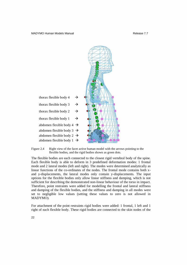
The thorax and the abdomen each consist of 4 flexible bodies. The flexible bodies divide the thorax and abdomen in horizontal slices, as is shown in Figure 2.4. The
geometry of the flexible bodies is determined by the position of the skin nodes of the
flexible body in concern. A point mass is assigned to each node.
MADYMO Human Models Manual Release 7.7
22
Figure 2.4 Right view of the facet active human model with the arrows pointing to the
flexible bodies, and the rigid bodies shown as green dots.
The flexible bodies are each connected to the closest rigid vertebral body of the spine. Each flexible body is able to deform in 3 predefined deformation modes: 1 frontal
mode and 2 lateral modes (left and right). The modes were determined analytically as
linear functions of the co-ordinates of the nodes. The frontal mode contains both x-
and y-displacements, the lateral modes only contain y-displacements. The input options for the flexible bodies only allow linear stiffness and damping, which is not
sufficient for describing the demonstrated non-linear behaviour of the torso in impact.
Therefore, point restraints were added for modelling the frontal and lateral stiffness and damping of the flexible bodies, and the stiffness and damping in all modes were
set to negligible low values (setting these values to zero is not allowed in
MADYMO).
For attachment of the point restraints rigid bodies were added: 1 frontal, 1 left and 1
right of each flexible body. These rigid bodies are connected to the skin nodes of the
thorax flexible body 4
thorax flexible body 3
thorax flexible body 2
thorax flexible body 1
abdomen flexible body 4
abdomen flexible body 3
abdomen flexible body 2
abdomen flexible body 1
MADYMO Human Models Manual Release 7.7
23
flexible body. The point restraints at the frontal bodies and the lateral bodies only contribute to loading in the x-direction and y-direction, respectively. Coupling
between frontal and lateral deformation is taken into account by the frontal
deformation mode.
Vertical point restrains were added between the rigid bodies of each flexible body.
These point restraints do not only have a z-component, but also have a small x- or y-
component for frontal respectively lateral stiffness. This was done in order to obtain a
more realistic skin deformation.
The two lowest flexible bodies also model the iliac wings. Since no biomechanic data
was available the resistance for frontal loading of these two lowest flexible bodies is
based on a model of the Hybrid III 50th percentile dummy.
2.1.5 Pelvis
The pelvis bone is modelled by facets. The facet pelvis can be used in contact with
the environment. For example in a frontal impact simulation with a lap belt defining contact between the belt and the skin and the facet pelvis will result in a more realistic
occupant response than with skin only.
2.1.6 Shoulders
The shoulder forms a moving base for the upper extremity. It consists of a number of joints connecting the humerus, scapula, clavicle and sternum. Furthermore, the
scapula contacts the back of the thorax; it can glide over the scapulothoracic gliding
plane. This connection makes the shoulder a closed chain mechanism. In the facet occupant models the clavicle, scapula and humerus are described by rigid bodies
connected by spherical joints. The geometry of the clavicles is represented by
cylinders, the geometry of the scapulae is represented by simple triangular elements,
as is shown in Figure 2.5.
The joint characteristics are based on biomechanical data from Engin (1984). The
clavicles and the sternum deform during shoulder loading. In the model such
deformations are incorporated by force models, which allow translational degrees of freedom between the clavicle and sternum. The translational deformation
characteristics are based on PMHS axial clavicle loading experiments as well as finite
element simulations of clavicle and rib cage loading.
In the real human body, the scapula contacts the thorax. Active muscle force is
needed to maintain this contact and to stabilise the shoulder girdle. These complex
interactions between shoulder and thorax are modelled as a set of passive force
models. The scapula is supported on the spine by point restraints to T1 and T9. Thus,

MADYMO Human Models Manual Release 7.7
24
the load transfer from shoulder to spine is modelled by the skeletal connection (scapula-clavicle-sternum-ribs-spine) and by these additional force models. The
resulting resistance of the shoulder model was verified against published quasi-static
volunteer test data as well as lateral impact data.
Figure 2.5 The shoulder model in frontal cross-sectional view. The co-ordinate systems
indicate the origins of the scapula joints, acromio-clavicular joints and
glenohumeral joints.
2.1.7 Limbs
The segments of the upper and lower limbs are all described by rigid bodies
connected by spherical joints. In impact conditions some passive bending is possible
in all rotational directions of all real human joints. Therefore, degrees of freedom, in which voluntary movement is not possible, are also included. The ranges of motion
(R.O.M.) of the different limb joints have been based on RAMSIS. Modelling has
been done by defining cardan or flexion torsion restraints with non-linear stiffness functions. The resistance parameters are based on literature data on passive human
joint properties (Engin et al. 1979-1989, Kapandji 1974, Ma et al. 1995).
The arm model contains 3-segment thumbs and a 3-segment description of the
combined fingers. The joints of thumbs and fingers have been locked, making the hands rigid. The leg model contains a 3-segment description of the foot. The joints
between the metatarsals (midfoot) and the foot have been locked. The outer geometry

MADYMO Human Models Manual Release 7.7
25
of the feet has the form of shoes. The geometry of these shoes is from GINO shoe models and has been obtained from RAMSIS.
2.1.8 Skin
The outer surface of the facet occupant model (skin) is described by a mesh of triangular elements defined as a null material. The skin is divided into several
sections that are supported on the nearest bodies. In the thorax and abdomen area the
skin is supported by flexible bodies. Different parts of the skin have different contact
characteristics, based on validation.
2.2 Model validation
The facet mid-size male occupant model has been validated extensively for impact
loading as described by de Lange et al. (2005). Two major categories of tests were
conducted: volunteer tests for low severity loading and post mortem human substitute (PMHS) tests for higher severity loading. The facet small female occupant model has
been validated as described in Happee et al. (2000a) using published small female
impactor corridors for the SID2s dummy (Daniel et al., 1995) and some other small
female PMHS tests. In sections 2.2.1 and 0 the blunt impactor tests and the sled tests that were used for the validation are described. The facet mid-size male occupant
model has also been validated for vertical vibration, see section 2.2.3.
Implementations of typical validation tests are described in the ‘examples’ section. The child human models are compared with corridors that were scaled based on a
method developed by Irwin & Mertz (1997). While the child models are merely
scaled adults, without a correct implementation of child specific structural and material differences, they are not validated models but research models.
2.2.1 Blunt impact tests
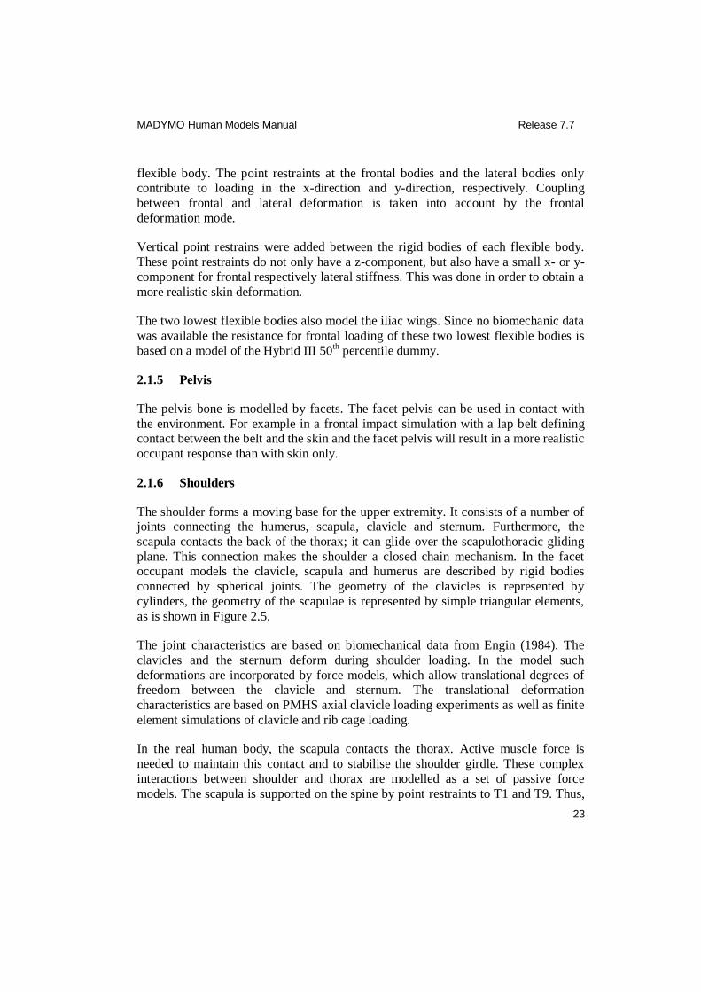
Blunt impact tests used for the validation of the facet occupant model are summarised
in Table 2.5. The modelled impactors of the various segment tests are all shown together with the male facet occupant model in Figure 2.6.
MADYMO Human Models Manual Release 7.7
26
Figure 2.6 Frontal impactor locations (thorax, abdomen) and lateral impactor locations
(shoulder, thorax, pelvis).

MADYMO Human Models Manual Release 7.7
27
Table 2.5 Blunt impact and drop tests used for validation of occupant models.
Model Test Reference
Segment Description Test object
Specifications
Small female shoulder
1 lateral impact PMHS 4.5 m/s, 14.0 kg Daniel et al. (1995)
Small female thorax
2 lateral impact PMHS 4.3, 6.7 m/s, 14.0 kg
Daniel et al. (1995)
Mid-size male head
2 frontal impact PMHSs 2.0, 5.5 m/s Don et al. (2003)
2 lateral drop PMHSs 2.0, 5.5 m/s ISO TR9790 (1997)
Mid-size male shoulders
4 lateral impact PMHSs 4.5-7 m/s ISO TR9790 (1997), Meyer et al. (1994), Lizee et al. (1998)
Mid-size male thorax
8 frontal impact PMHSs 3.4–9.9 m/s, 10.4–23.4 kg
Bouquet et al. (1994),
Neathery (1974), Kroell et al. (1971, 1974, 1976), Nahum et al. (1970,1975)
4 lateral impact PMHSs 3.3-6.7 m/s, 23.0-23.4 kg
Lizee et al. (1998), Talantikite et al. (1998), ISO TR9790 (1997)
2 rigid drop tests
PMHS 4.5, 6.3 m/s ISO TR9790 (1997)
Mid-size male abdomen
3 frontal impact PMHSs 6.1-10.4 m/s, 18.0-63.6 kg
Cavanaugh (1986), GESAC (2001), Don et al. (2003)
2 rigid drop tests on armrest
PMHSs 4.5, 6.3 m/s ISO TR9790 (1997)
Mid-size male pelvis
6 lateral impact PMHSs 3.5-10.0 m/s, 17.3-23.4 kg
Bouquet et al. (1994), ISO TR9790 (1997)
2 rigid drop tests
PMHSs 3.2, 4.5 m/s ISO TR9790 (1997)
Small female Side airbag deployment
PMHSs Happee et al. (2000a)
2.2.2 Sled tests
Sled tests used for the validation of the full body behaviour of the facet occupant
models are summarised in Table 2.6.

MADYMO Human Models Manual Release 7.7
28
Table 2.6 Sled tests used for validation of the full body behaviour of the facet occupant
models.
Model Test Reference
Description test object specifications
Mid-size male 9 frontal rigid seat sled tests
5 volunteers 15 G peak Thunnissen (1995)
Mid-size male 2 rear deformable seat sled tests
2 volunteers 4-5 G peak Kroonenberg et al. (1998)
Mid-size male 9 rear rigid seat sled tests
9 volunteers 3.6 G peak Ono et al. (1999)
Mid-size male 9 rear deformable seat sled tests
9 volunteers 3.6 G peak Ono et al. (1999)
Mid-size male 6 rear rigid seat sled tests
3 PMHS 9-12 G peak Bertholon et al. (2000)
Mid-size male Lateral rigid seat sled test
volunteer 6.7 G peak Ewing (1972)
Mid-size male Lateral rigid seat sled tests
PMHSs 20, 37 G peak, 6.8, 8.9 m/s
Happee et al. (2000a), ISO TR9790 (1997)
Mid-size male oblique rigid seat sled test
volunteer 11 G peak Philippens et al. (2004)
2.2.3 Vertical vibration
Vertical vibration tests used for the validation of the full body behaviour of the mid-
size-male facet occupant model are summarised in Table 2.7.
Table 2.7 Vertical vibration tests used for validation of mid-size male occupant models.
Model Test Reference
Description Test object Specifications
Facet mid-size male occupant
Vibration tests on rigid seat
11 volunteers 0.5-15 Hz, 0.4 G peak
Verver et al. (2003)
Facet mid-size male occupant
Vibration tests on standard car seat
11 volunteers 0.5-15 Hz, 0.4 G peak
Verver et al. (2003)
MADYMO Human Models Manual Release 7.7
29
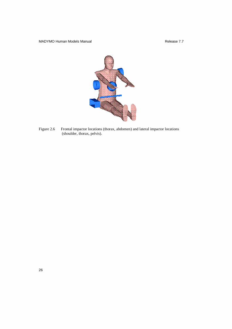
2.2.4 Child model validation
The dynamic hub impactor tests of Neathery (1974) were simulated with all child
occupant models. The impactor mass and diameter were scaled according to the Irwin
& Mertz (1997) scaling method. An overview of the various simulations is given in Table 2.8. Additional data used to validate the 6 year old child model are summarized
in Table 2.9.
Table 2.8 Hub impactor tests used for assessment of performance of child occupant
models.
Model Test Reference
Description Test object Specifications
1.5-year-old Hub impactor test
Scaled corridor
2.9 kg, 4.3 and 6.7 m/s
Neathery (1974)
Irwin and Mertz (1997)
3-year-old Hub impactor test
Scaled corridor
3.8 kg, 4.3 and 6.7 m/s
Neathery (1974)
Irwin and Mertz (1997)
6-year-old Hub impactor test
Scaled corridor
5.3 kg, 4.3 and 6.7 m/s
Neathery (1974)
Irwin and Mertz (1997)
10-year-old Hub impactor test
Scaled corridor
10.0 kg, 4.3 and 6.7 m/s
Neathery (1974)
Irwin and Mertz (1997)
Table 2.9 Additional datasets used for validation of the 6 year old child model
Model Test Reference
Description Test object
Specifications
6-year-old Frontal thoracic pendulum
5 PMHS 3.5 kg, 6 m/s Ouyang et al (2006)
6-year-old Abdominal belt loading test
47 porcine 2 locations, 3 rates Kent et al (2006)
6-year-old Neck tension test
9 PMHS Quasi static Ouyang et al. (2005)

MADYMO Human Models Manual Release 7.7
30
2.3 User instructions
2.3.1 Integration method and time step
The recommended integration method and minimum integration time step for the
facet occupant models is given in Table 2.10.
Table 2.10 Recommended integration method and time step for the facet occupant models.
Model Integration method Time step (s)
Small female EULER ≤1.0E-05
Mid-size male EULER ≤1.0E-05
Large male EULER ≤1.0E-05
2.3.2 Positioning
Because of the flexibility of the facet occupant model’s spine and neck, it is a bit
more complex to position this model in a seat than a dummy model. The occupant
model must be in an equilibrium state at the start of a simulation. Otherwise, initial accelerations will take place. A pre-simulation is generally required to obtain this
equilibrium. Positioning of the facet occupant model is done in four steps:
1. The complete occupant model is positioned and orientated correctly with respect to its environment by initialising the position and orientation of the human joint
(Human_jnt). Vertebrae can be orientated in order to put the spine in a seating
position. The occupant model can best be positioned just above the seat with its pelvis at the correct horizontal position. In a relaxed seating position the human
spine is curved differently than in a standing position or a straight seating
position. To model a relaxed seating position the vertebral joints of the facet
occupant model can be rotated in the user-file in ORIENTATION.SUCCESSIVE_ROT. To put the spine of the facet occupant
model in a relaxed seating position the initial vertebral joint rotations should be
changed to the values given in Table 2.11 (seating position according to Davidsson et al. (1998)).
2. The extremities are orientated with respect to the parent component by changing
the orientation of the joints in the positioning elements (INITIAL.JOINT_POS).
The occupant can for example be put in a driving position.
MADYMO Human Models Manual Release 7.7
31
3. A pre-simulation is performed in which the facet occupant model is put into the seat by a gravitational field only (acceleration field of -9.81 m/s
2 in z-direction).
The run time for positioning the facet occupant model needs to be large enough
for the occupant to find its equilibrium (typically about 1 s). To maintain the facet occupant model in an upright position when subjected to gravity, several methods
can be used. Depending on the situation a different positioning is preferred. In
case of simulations of live human behaviour, the active human model is
recommended (see Chapter 2). For PMHS tests, there are two options: however one likes to simulate a certain test, one should take into account the way the
PMHS was settled. For example, if the PHMS was kept upright with an
electromagnet attached to the top of his head, option a should be used. Option b is preferred for general simulations of PMHS behaviour.
a. To keep the head upright, a support as often applied in PMHS tests can
be simulated by defining a point-restraint with a constant force of 100 N in the z-direction (this compensates for the weight of the head and
vertebral masses) just above the head CG.
b. The settling of a human subject with only passive behaviour can be
simulated by defining a cardan restraint of about 1000 Nm/rad between OC and inertial space together with a point restraint of about 1000 N/m in
the x-direction and y-direction between the head and inertial space. For
an example file, see ‘e_occ50fc_pos_b.xml’ in $MADHOME/share/appl/3d.
4. joint position degrees of freedom (JOINT_DOF) of all joints in the user-file
should be defined in the output. The joints of which the initial positions are not
defined in the user-file should be locked. The output from the last time step in the JNTPOS file of the pre-simulation should be copied to the positioning elements
(INITIAL.JOINT_POS) of the impact simulation file. In the impact simulation
the user should remove the restraints used in the pre-simulation
When all joints in INITIAL.JOINT_POS are set to zero (except for the ankles), the
facet occupant model is in an erect standing position as is shown in Figure 2.7. This
position is called the reference position. In this position the joint translations and rotations are defined as shown in Figure 2.7. The default position is a seating position
as is shown in Figure 2.1.
The orientations of the translational (D) and rotational (R) DOF of the facet occupant
model positioning joints are given in Table 2.14. The positioning joints are schematically drawn in Figure 2.8.

MADYMO Human Models Manual Release 7.7
32
Figure 2.7 Definition of joint translations and rotations of the facet occupant models. The occupant model is in its reference position.
Figure 2.8 Locations of positioning joints of the facet occupant model.
}
Scapula-ArmUp
Elbow
C7-T1, …, C1-Head
} L5-L4, …, T2-T1
Human joint Hip
Wrist
Knee
Ankle
Sacrum-L5
x
y
z
roll right
pitch down
yaw left

MADYMO Human Models Manual Release 7.7
33
The model contains a large number of degrees of freedom, where many of these have only a limited range of motion. To obtain a realistic initial position care should be
taken that user-defined initial rotations and translations are within the range of
motion. Reasonable initial rotations of the limbs can be determined directly from the ranges of motion that are specified in the cardan and flexion-torsion restraint models
of the limbs. For the neck and spine joints both initial rotations and translations can
be specified. For neck and spine the ranges of motion cannot be seen in the user-file
nor in the include-file, since the joint resistance models are protected. Therefore, some information on the range of motion is given in Table 2.12 and Table 2.13.

MADYMO Human Models Manual Release 7.7
34
Table 2.11: Vertebral joint rotations in a relaxed seating position according to Davidsson et.
al. (1998).
Joint orientation identifier
Degree of freedom
R1 R2 R3
Sacrum-L5_ori 0 0.1021 0
L5-L4_ori 0 0.0821 0
L4-L3_ori 0 0.0348 0
L3-L2_ori 0 0.0348 0
L2-L1_ori 0 0.0348 0
L1-T12_ori 0 0.0346 0
T12-T11_ori 0 0.0346 0
T11-T10_ori 0 0.0346 0
T10-T9_ori 0 0.0346 0
T9-T8_ori 0 0.0346 0
T8-T7_ori 0 0.0346 0
T7-T6_ori 0 0.0346 0
T6-T5_ori 0 0.0346 0
T5-T4_ori 0 0.0146 0
T4-T3_ori 0 0.0146 0
T3-T2_ori 0 0.0146 0
T2-T1_ori 0 0.0146 0
T1-C7_ori 0 0 0
C7-C6_ori 0 0 0
C6-C5_ori 0 0 0
C5-C4_ori 0 0 0
C4-C3_ori 0 0 0
C3-C2_ori 0 0 0
C2-C1_ori 0 0 0
C1-Head_ori 0 0 0

MADYMO Human Models Manual Release 7.7
35
Table 2.12 Joints ranges of rotations.
Joint Minimum motion [rad]
Torque min. motion [Nm]
Maximum motion [rad]
Torque max. motion [Nm]
C0-C1:
roll right -0.0515 -1.5 0.0515 1.5
pitch down -0.1707 -7.5 0.1014 1.3
yaw left -0.0637 -1.5 0.0637 1.5
C1-C2:
roll right -0.0977 -10 0.0977 10
pitch down -0.1002 -7.5 0.1225 5
yaw left -0.3752 -1.5 0.3752 1.5
C2-C3:
roll right -0.105 -10 0.105 10
pitch down -0.0473 -7.5 0.0577 5
yaw left -0.0312 -1.5 0.0312 1.5
C3-C4:
roll right -0.1152 -10 0.1152 10
pitch down -0.0701 -7.5 0.0871 5
yaw left -0.0732 -1.5 0.0732 1.5
C4-C5:
roll right -0.1152 -10 0.1152 10
pitch down -0.0628 -7.5 0.1166 5
yaw left -0.0732 -1.5 0.0732 1.5
C5-C6:
roll right -0.084 -10 0.084 10
pitch down -0.0728 -7.5 0.1166 5
yaw left -0.0732 -1.5 0.0732 1.5
C6-C7:
roll right -0.0732 -10 0.0732 10
pitch down -0.0793 -2 0.0986 5
yaw left -0.063 -1.5 0.063 1.5
C7-T1:
roll right -0.042 -10 0.042 10

MADYMO Human Models Manual Release 7.7
36
Joint Minimum motion [rad]
Torque min. motion [Nm]
Maximum motion [rad]
Torque max. motion [Nm]
pitch down -0.0419 -7.5 0.0523 5
Yaw left -0.021 -1.5 0.021 1.5
Thoracic joints:
pitch down -0.036 -48 0.065 88.14
roll right -0.03 -40.68 0.03 40.68
Yaw left -0.0509 -15.27 0.0509 15.27
Lumbar joints:
pitch down -0.122 -83 0.2094 142
roll right -0.1033 -25.8 0.1033 25.8
Yaw left -0.0175 -14.175 0.0175 14.175
Table 2.13 Joints ranges of displacements.
Joints Minimum disp [m]
Force at min. disp [N]
Maximum disp [m]
Force at max. disp [N]
T1-C2:
x-displacement -0.0001 -50 0.0011 50
y-displacement -0.0009 -50 0.0009 50
z-displacement -0.0007 -200 0.0033 400
Table 2.14 Positioning joints of the facet occupant models.
Joint description Identifier Degree of freedom
D1 / R1 D2 / R2 D3 / R3
Complete human Human_jnt X / Roll right Y / Pitch down Z / Yaw left
Sacrum-lumbar disc (L5-S1) Sacrum-L5_jnt Roll right Pitch down Yaw left
Lumbar interverterbal disc L5-L4_jnt Roll right Pitch down Yaw left
,, L4-L3_jnt Roll right Pitch down Yaw left
,, L3-L2_jnt Roll right Pitch down Yaw left
,, L2-L1_jnt Roll right Pitch down Yaw left
,, L1-T12_jnt Roll right Pitch down Yaw left

MADYMO Human Models Manual Release 7.7
37
Joint description Identifier Degree of freedom
D1 / R1 D2 / R2 D3 / R3
Thoracic intervertebral disc T12-T11_jnt Roll right Pitch down Yaw left
,, T11-T10_jnt Roll right Pitch down Yaw left
,, T10-T9_jnt Roll right Pitch down Yaw left
,, T9-T8_jnt Roll right Pitch down Yaw left
,, T8-T7_jnt Roll right Pitch down Yaw left
,, T7-T6_jnt Roll right Pitch down Yaw left
,, T6-T5_jnt Roll right Pitch down Yaw left
,, T5-T4_jnt Roll right Pitch down Yaw left
,, T4-T3_jnt Roll right Pitch down Yaw left
,, T3-T2_jnt Roll right Pitch down Yaw left
,, T2-T1_jnt Roll right Pitch down Yaw left
Cervical intervertebral disc T1-C7_jnt Roll right Pitch down Yaw left
,, C7-C6_jnt Roll right Pitch down Yaw left
,, C6-C5_jnt Roll right Pitch down Yaw left
,, C5-C4_jnt Roll right Pitch down Yaw left
,, C4-C3_jnt Roll right Pitch down Yaw left
,, C3-C2_jnt Roll right Pitch down Yaw left
,, C2-C1_jnt Roll right Pitch down Yaw left
,, C1-Head_jnt Roll right Pitch down Yaw left
Right glenohumeral joint ScapulaR-ArmUpR_jnt Roll right Yaw left Pitch down
Right elbow ElbowR_jnt Yaw right Pitch down
Right wrist WristR_jnt Roll right
Left glenohumeral joint ScapulaL-ArmUpL_jnt Roll right Yaw left Pitch down
Left elbow ElbowL_jnt Yaw right Pitch down
Left wrist WristL_jnt Roll right
Right hip HipR_jnt Pitch down Roll right Yaw left
Right knee KneeR_jnt Roll right Pitch down Yaw left
Right ankle AnkleR_jnt Pitch down Roll right Yaw left
Left hip HipL_jnt Pitch down Roll right Yaw left
Left knee KneeL_jnt Roll right Pitch down Yaw left
Left ankle AnkleL_jnt Pitch down Roll right Yaw left
MADYMO Human Models Manual Release 7.7
38
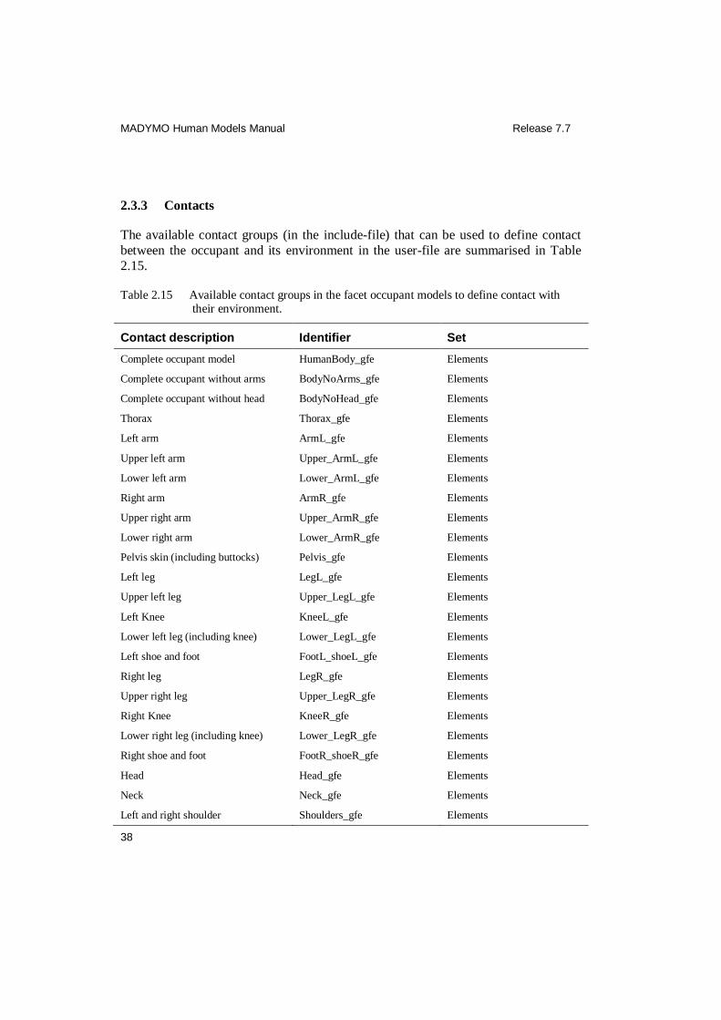
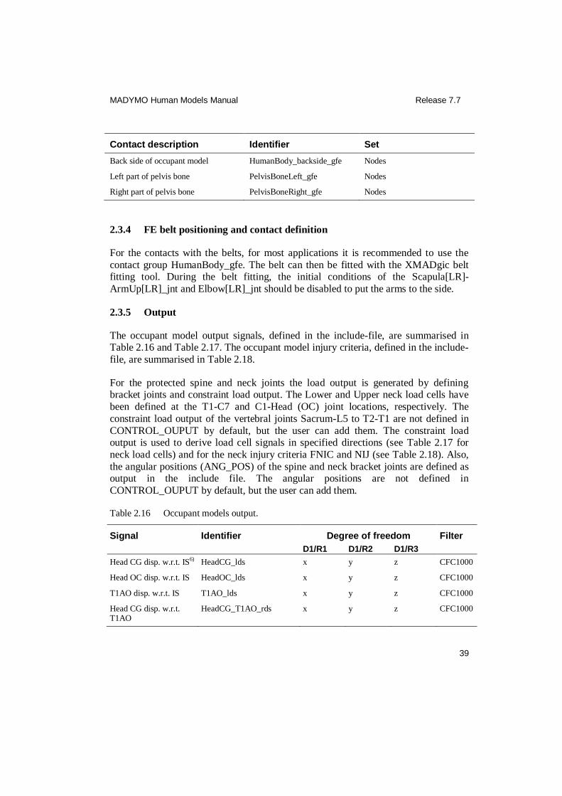
2.3.3 Contacts
The available contact groups (in the include-file) that can be used to define contact
between the occupant and its environment in the user-file are summarised in Table
2.15.
Table 2.15 Available contact groups in the facet occupant models to define contact with their environment.
Contact description Identifier Set
Complete occupant model HumanBody_gfe Elements
Complete occupant without arms BodyNoArms_gfe Elements
Complete occupant without head BodyNoHead_gfe Elements
Thorax Thorax_gfe Elements
Left arm ArmL_gfe Elements
Upper left arm Upper_ArmL_gfe Elements
Lower left arm Lower_ArmL_gfe Elements
Right arm ArmR_gfe Elements
Upper right arm Upper_ArmR_gfe Elements
Lower right arm Lower_ArmR_gfe Elements
Pelvis skin (including buttocks) Pelvis_gfe Elements
Left leg LegL_gfe Elements
Upper left leg Upper_LegL_gfe Elements
Left Knee KneeL_gfe Elements
Lower left leg (including knee) Lower_LegL_gfe Elements
Left shoe and foot FootL_shoeL_gfe Elements
Right leg LegR_gfe Elements
Upper right leg Upper_LegR_gfe Elements
Right Knee KneeR_gfe Elements
Lower right leg (including knee) Lower_LegR_gfe Elements
Right shoe and foot FootR_shoeR_gfe Elements
Head Head_gfe Elements
Neck Neck_gfe Elements
Left and right shoulder Shoulders_gfe Elements
MADYMO Human Models Manual Release 7.7
39
Contact description Identifier Set
Back side of occupant model HumanBody_backside_gfe Nodes
Left part of pelvis bone PelvisBoneLeft_gfe Nodes
Right part of pelvis bone PelvisBoneRight_gfe Nodes
2.3.4 FE belt positioning and contact definition
For the contacts with the belts, for most applications it is recommended to use the
contact group HumanBody_gfe. The belt can then be fitted with the XMADgic belt fitting tool. During the belt fitting, the initial conditions of the Scapula[LR]-
ArmUp[LR]_jnt and Elbow[LR]_jnt should be disabled to put the arms to the side.
2.3.5 Output
The occupant model output signals, defined in the include-file, are summarised in Table 2.16 and Table 2.17. The occupant model injury criteria, defined in the include-
file, are summarised in Table 2.18.
For the protected spine and neck joints the load output is generated by defining bracket joints and constraint load output. The Lower and Upper neck load cells have
been defined at the T1-C7 and C1-Head (OC) joint locations, respectively. The
constraint load output of the vertebral joints Sacrum-L5 to T2-T1 are not defined in
CONTROL_OUPUT by default, but the user can add them. The constraint load output is used to derive load cell signals in specified directions (see Table 2.17 for
neck load cells) and for the neck injury criteria FNIC and NIJ (see Table 2.18). Also,
the angular positions (ANG_POS) of the spine and neck bracket joints are defined as output in the include file. The angular positions are not defined in
CONTROL_OUPUT by default, but the user can add them.
Table 2.16 Occupant models output.
Signal Identifier Degree of freedom Filter
D1/R1 D1/R2 D1/R3
Head CG disp. w.r.t. IS6) HeadCG_lds x y z CFC1000
Head OC disp. w.r.t. IS HeadOC_lds x y z CFC1000
T1AO disp. w.r.t. IS T1AO_lds x y z CFC1000
Head CG disp. w.r.t. T1AO
HeadCG_T1AO_rds x y z CFC1000

MADYMO Human Models Manual Release 7.7
40
Signal Identifier Degree of freedom Filter
D1/R1 D1/R2 D1/R3
Head OC disp. w.r.t. T1AO
HeadOC_T1AO_rds x y z CFC1000
Sternum velocities w.r.t. T1AO
Sternum_T1AO_dvl x y z CFC600
Ribs n velocities w.r.t. spine body
Ribsn_Spine_dvl1) y x z CFC180
Head CG acc. w.r.t IS HeadCG_lac x y z CFC1000
Head OC acc. w.r.t. IS HeadOC_lac x y z CFC1000
T1AO acc. w.r.t. IS T1AO_lac x y z CFC1000
Sternum acc. w.r.t. IS Sternum_lac x y z CFC1000
Sternum_CFC180_lac x y z CFC180
Pelvis acc. w.r.t. IS Pelvis_lac x y z CFC1000
Head CG angular acc. HeadCG_aac Roll right Pitch down Yaw left CFC1000
T1 angular acc. T1_aac Roll right Pitch down Yaw left CFC1000
Frontal abdomen disp. w.r.t. spine body
AbdomenFrontn1,2) x y z
Frontal thorax disp. w.r.t. spine body
ThoraxFrontn1,2) x y z
Right abdomen disp. w.r.t. spine body
AbdomenRn1,2) x y z
Right thorax disp. w.r.t. spine body
ThoraxRn1,2) x y z
Left abdomen disp. w.r.t. spine body
AbdomenLn1,2) x y z
Left thorax disp. w.r.t. spine body
ThoraxLn1,2) x y z
Head w.r.t. T1 cardan output2)
Head_wrt_T13) Roll right Pitch down Yaw left
T1 w.r.t. inertial space cardan output
T1_wrt_RefSpace3) Roll right Pitch down Yaw left
Head w.r.t. IS cardan output
Head_RefSpace3) Roll right Pitch down Yaw left
Lower neck torque NeckLow_Torque4) Roll right Pitch down Yaw left CFC600
Lower neck force NeckLow_Force4) x Y z CFC1000
Upper neck torque NeckUp_Torque4) Roll right Pitch down Yaw left CFC600
MADYMO Human Models Manual Release 7.7
41
Signal Identifier Degree of freedom Filter
D1/R1 D1/R2 D1/R3
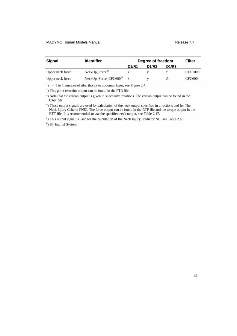
Upper neck force NeckUp_Force4) x y z CFC1000
Upper neck force NeckUp_Force_CFC6005) x y Z CFC600
1) n = 1 to 4, number of ribs, thorax or abdomen layer, see Figure 2.4. 2) This point restraint output can be found in the PTR file. 3) Note that the cardan output is given in successive rotations. The cardan output can be found in the
CAN file. 4) These output signals are used for calculation of the neck output specified in directions and for The
Neck Injury Criteria FNIC. The force output can be found in the RTF file and the torque output in the RTT file. It is recommended to use the specified neck output, see Table 2.17.
5) This output signal is used for the calculation of the Neck Injury Predictor NIJ, see Table 2.18. 6) IS=Inertial System

MADYMO Human Models Manual Release 7.7
42
Table 2.17 Occupant models load cell output of lower and upper neck in specified directions.
Signal Identifier Degree of freedom Filter
D1/R1 D1/R2 D1/R3
Spec. lower neck forces:
Resultant NeckLowFRES1) CFC1000
For-rearward shear NeckLowFX_SHEAR1) x CFC1000
Lateral shear NeckLowFY_SHEAR1) y CFC1000
Axial NeckLowFZ_AXIAL1) z CFC1000
Spec. lower neck torques:
Resultant NeckLowMRES1) CFC600
Lateral NeckLowMX_ROLL1) Roll right CFC600
For-rearward NeckLowMY_PITCH1) Pitch down CFC600
Axial NeckLowMZ_YAW1) Yaw left CFC600
Spec. upper neck forces:
Resultant NeckUpFRES1) CFC1000
For-rearward shear NeckUpFX_SHEAR1) x CFC1000
Lateral shear NeckUpFY_SHEAR1) y CFC1000
Axial NeckUpFZ_AXIAL1) z CFC1000
Spec. upper neck torques:
Resultant NeckUpMRES1) CFC600
Lateral NeckUpMX_ROLL1) Roll right CFC600
For-rearward NeckUpMY_PITCH1) Pitch down CFC600
Axial NeckUpMZ_YAW1) Yaw left CFC600
1) The load cell output can be found in the INJURY file.
MADYMO Human Models Manual Release 7.7
43
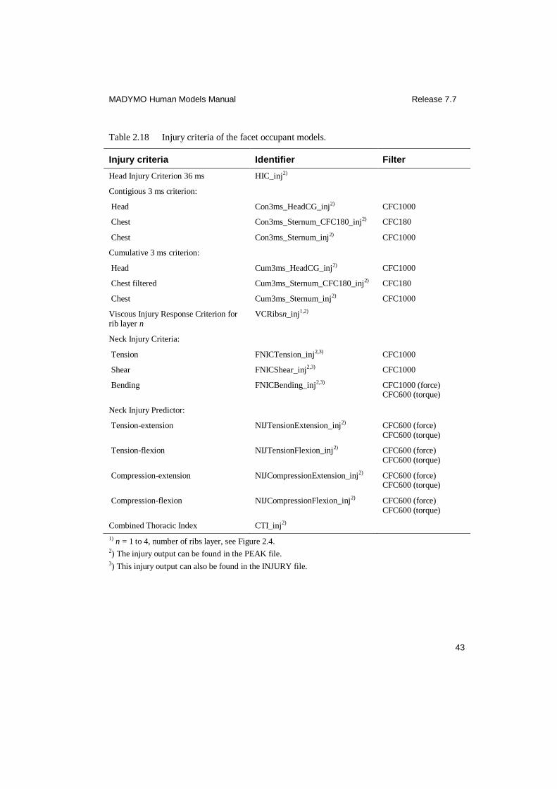
Table 2.18 Injury criteria of the facet occupant models.
Injury criteria Identifier Filter
Head Injury Criterion 36 ms HIC_inj2)
Contigious 3 ms criterion:
Head Con3ms_HeadCG_inj2) CFC1000
Chest Con3ms_Sternum_CFC180_inj2) CFC180
Chest Con3ms_Sternum_inj2) CFC1000
Cumulative 3 ms criterion:
Head Cum3ms_HeadCG_inj2) CFC1000
Chest filtered Cum3ms_Sternum_CFC180_inj2) CFC180
Chest Cum3ms_Sternum_inj2) CFC1000
Viscous Injury Response Criterion for rib layer n
VCRibsn_inj1,2)
Neck Injury Criteria:
Tension FNICTension_inj2,3) CFC1000
Shear FNICShear_inj2,3) CFC1000
Bending FNICBending_inj2,3) CFC1000 (force) CFC600 (torque)
Neck Injury Predictor:
Tension-extension NIJTensionExtension_inj2) CFC600 (force) CFC600 (torque)
Tension-flexion NIJTensionFlexion_inj2) CFC600 (force) CFC600 (torque)
Compression-extension NIJCompressionExtension_inj2) CFC600 (force) CFC600 (torque)
Compression-flexion NIJCompressionFlexion_inj2) CFC600 (force) CFC600 (torque)
Combined Thoracic Index CTI_inj2)
1) n = 1 to 4, number of ribs layer, see Figure 2.4. 2) The injury output can be found in the PEAK file. 3) This injury output can also be found in the INJURY file.
MADYMO Human Models Manual Release 7.7
44
2.4 Examples
2.4.1 Frontal impact with a belt
An example application file of the facet occupant model with belts in a frontal impact
‘e_occ50fc_imp.xml’ can be found in $MADHOME/share/appl/3d.
2.4.2 Occupant model positioning method b
In section 2.3.2 different positioning methods have been described. Method ‘b’ is demonstrated in an example ‘e_occ50fc_pos_b.xml’, which can be found in
$MADHOME/share/appl/3d.

MADYMO Human Models Manual Release 7.7
45
3 Facet active human model
The MADYMO facet active human model is described in the Madymo Model
manual.

MADYMO Human Models Manual Release 7.7
46
4 Facet pedestrian model
The MADYMO facet pedestrian model described in this chapter is currently released
in one body size, being a mid-size male model representing the 50th percentile male
model population (Figure 4.1). This model is identical to the standing active human
model (Chapter 3), except for the controllers, which are not included in the facet
pedestrian model.
Figure 4.1 Facet pedestrian model.

MADYMO Human Models Manual Release 7.7
47
4.1 Model description A facet mid-size male pedestrian model is available. The input is given in the files:
Mid-size male: h_ped50fc_usr.xml
h_ped50fc_inc.xml
To run this model, the following licenses are required:
Mid-size male: MADYMO/Solver (Multibody)
MADYMO/Human Models/Pedestrian
Since the facet pedestrian model is identical to the standing active human model
(Chapter 3), except for the active behaviour, for the model description is referred to
Error! Reference source not found. - Error! Reference source not found..
4.2 Model validation
The facet pedestrian model was validated using all post mortem human subject (PMHS) tests described in section Error! Reference source not found.. Since the
facet pedestrian model is identical to the standing facet active human model without
active behaviour, the responses of this model are almost similar to that of the standing active human model in the PMHS tests.
4.3 User instructions
4.3.1 Integration method and time step
Table 4.1 Recommended integration method and time step for the facet pedestrian model.
Model Integration method Time step (s)
Mid-size male EULER <1.0E-05
4.3.2 Positioning
In order to position the facet pedestrian model, the INITIAL.JOINT_POS elements
have to be used. All joints that are needed for positioning the facet pedestrian model are defined in the INITIAL.JOINT_POS elements in the user-file. Positions of all
other joints are defined in the include-file, and these should not be edited by the user.
MADYMO Human Models Manual Release 7.7
48
A human model is by default positioned relative to the (global) reference space coordinate system. However, the human model can be positioned relative to a body of
another system. This can be done in the CRDSYS_OBJECT ‘Human_Attachment’
and the associated ORIENTATION ‘Human_Attachment_ori’. The human attachment element ‘Human_Attachment’ is comparable to the dummy attachment
element 'Dummy_attachment' in a dummy model, which is located at the H-point.
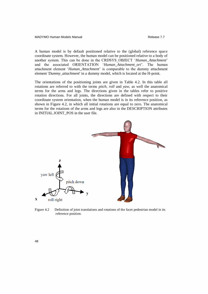
The orientations of the positioning joints are given in Table 4.2. In this table all
rotations are referred to with the terms pitch, roll and yaw, as well the anatomical terms for the arms and legs. The directions given in the tables refer to positive
rotation directions. For all joints, the directions are defined with respect to their
coordinate system orientation, when the human model is in its reference position, as shown in Figure 4.2, in which all initial rotations are equal to zero. The anatomical
terms for the rotations of the arms and legs are also in the DESCRIPTION attributes
in INITIAL.JOINT_POS in the user file.
Figure 4.2 Definition of joint translations and rotations of the facet pedestrian model in its
reference position.
MADYMO Human Models Manual Release 7.7
49
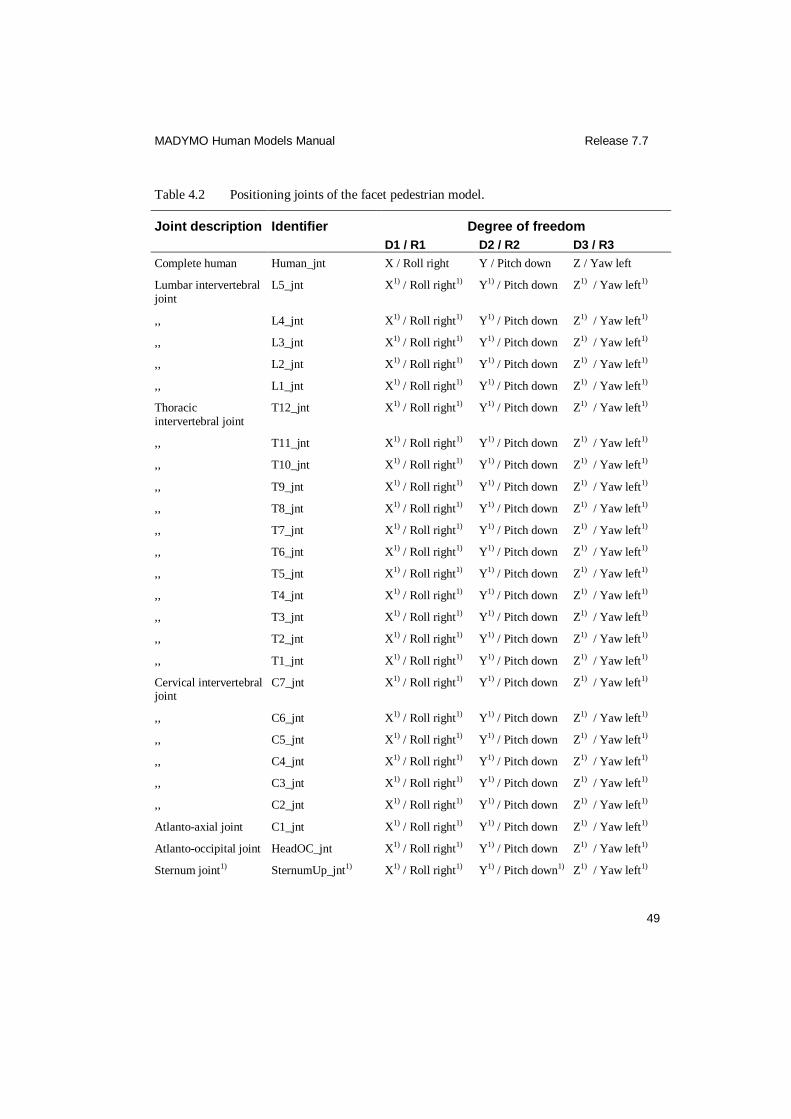
Table 4.2 Positioning joints of the facet pedestrian model.
Joint description Identifier Degree of freedom
D1 / R1 D2 / R2 D3 / R3
Complete human Human_jnt X / Roll right Y / Pitch down Z / Yaw left
Lumbar intervertebral joint
L5_jnt X1) / Roll right1) Y1) / Pitch down Z1) / Yaw left1)
,, L4_jnt X1) / Roll right1) Y1) / Pitch down Z1) / Yaw left1)
,, L3_jnt X1) / Roll right1) Y1) / Pitch down Z1) / Yaw left1)
,, L2_jnt X1) / Roll right1) Y1) / Pitch down Z1) / Yaw left1)
,, L1_jnt X1) / Roll right1) Y1) / Pitch down Z1) / Yaw left1)
Thoracic intervertebral joint
T12_jnt X1) / Roll right1) Y1) / Pitch down Z1) / Yaw left1)
,, T11_jnt X1) / Roll right1) Y1) / Pitch down Z1) / Yaw left1)
,, T10_jnt X1) / Roll right1) Y1) / Pitch down Z1) / Yaw left1)
,, T9_jnt X1) / Roll right1) Y1) / Pitch down Z1) / Yaw left1)
,, T8_jnt X1) / Roll right1) Y1) / Pitch down Z1) / Yaw left1)
,, T7_jnt X1) / Roll right1) Y1) / Pitch down Z1) / Yaw left1)
,, T6_jnt X1) / Roll right1) Y1) / Pitch down Z1) / Yaw left1)
,, T5_jnt X1) / Roll right1) Y1) / Pitch down Z1) / Yaw left1)
,, T4_jnt X1) / Roll right1) Y1) / Pitch down Z1) / Yaw left1)
,, T3_jnt X1) / Roll right1) Y1) / Pitch down Z1) / Yaw left1)
,, T2_jnt X1) / Roll right1) Y1) / Pitch down Z1) / Yaw left1)
,, T1_jnt X1) / Roll right1) Y1) / Pitch down Z1) / Yaw left1)
Cervical intervertebral joint
C7_jnt X1) / Roll right1) Y1) / Pitch down Z1) / Yaw left1)
,, C6_jnt X1) / Roll right1) Y1) / Pitch down Z1) / Yaw left1)
,, C5_jnt X1) / Roll right1) Y1) / Pitch down Z1) / Yaw left1)
,, C4_jnt X1) / Roll right1) Y1) / Pitch down Z1) / Yaw left1)
,, C3_jnt X1) / Roll right1) Y1) / Pitch down Z1) / Yaw left1)
,, C2_jnt X1) / Roll right1) Y1) / Pitch down Z1) / Yaw left1)
Atlanto-axial joint C1_jnt X1) / Roll right1) Y1) / Pitch down Z1) / Yaw left1)
Atlanto-occipital joint HeadOC_jnt X1) / Roll right1) Y1) / Pitch down Z1) / Yaw left1)
Sternum joint1) SternumUp_jnt1) X1) / Roll right1) Y1) / Pitch down1) Z1) / Yaw left1)
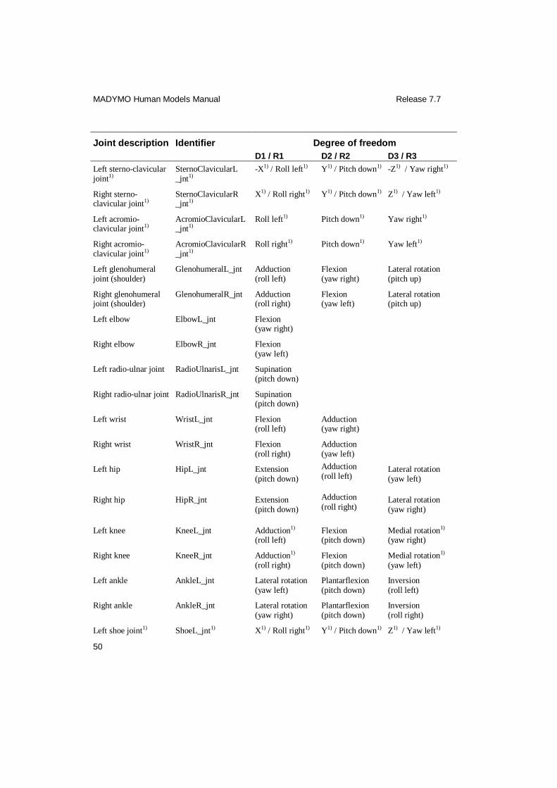
MADYMO Human Models Manual Release 7.7
50
Joint description Identifier Degree of freedom
D1 / R1 D2 / R2 D3 / R3
Left sterno-clavicular joint1)
SternoClavicularL _jnt1)
-X1) / Roll left1) Y1) / Pitch down1) -Z1) / Yaw right1)
Right sterno-clavicular joint1)
SternoClavicularR _jnt1)
X1) / Roll right1) Y1) / Pitch down1) Z1) / Yaw left1)
Left acromio-clavicular joint1)
AcromioClavicularL_jnt1)
Roll left1) Pitch down1) Yaw right1)
Right acromio-clavicular joint1)
AcromioClavicularR_jnt1)
Roll right1) Pitch down1) Yaw left1)
Left glenohumeral joint (shoulder)
GlenohumeralL_jnt Adduction (roll left)
Flexion (yaw right)
Lateral rotation (pitch up)
Right glenohumeral joint (shoulder)
GlenohumeralR_jnt Adduction (roll right)
Flexion (yaw left)
Lateral rotation (pitch up)
Left elbow ElbowL_jnt Flexion (yaw right)
Right elbow ElbowR_jnt Flexion (yaw left)
Left radio-ulnar joint RadioUlnarisL_jnt Supination (pitch down)
Right radio-ulnar joint RadioUlnarisR_jnt Supination (pitch down)
Left wrist WristL_jnt Flexion (roll left)
Adduction (yaw right)
Right wrist WristR_jnt Flexion (roll right)
Adduction (yaw left)
Left hip HipL_jnt Extension (pitch down)
Adduction (roll left)
Lateral rotation (yaw left)
Right hip HipR_jnt Extension (pitch down)
Adduction
(roll right) Lateral rotation (yaw right)
Left knee KneeL_jnt Adduction1) (roll left)
Flexion (pitch down)
Medial rotation1) (yaw right)
Right knee KneeR_jnt Adduction1) (roll right)
Flexion (pitch down)
Medial rotation1) (yaw left)
Left ankle AnkleL_jnt Lateral rotation (yaw left)
Plantarflexion (pitch down)
Inversion (roll left)
Right ankle AnkleR_jnt Lateral rotation (yaw right)
Plantarflexion (pitch down)
Inversion (roll right)
Left shoe joint1) ShoeL_jnt1) X1) / Roll right1) Y1) / Pitch down1) Z1) / Yaw left1)

MADYMO Human Models Manual Release 7.7
51
Joint description Identifier Degree of freedom
D1 / R1 D2 / R2 D3 / R3
Right shoe joint1) ShoeR_jnt1) X1) / Roll right1) Y1) / Pitch down1) Z1) / Yaw left1)
1) Not to be changed during manual positioning. Only for equilibrium, based on a settling simulation.
4.3.3 Contacts
Table 4.3 Available contact groups in the facet pedestrian model to define contact with its
environment.
Contact description Identifier Set
Complete human model HumanBody_gfe Elements and nodes
Complete human without arms BodyNoArms_gfe Elements and nodes
Complete human without head BodyNoHead_gfe Elements and nodes
Head Head_gfe Elements and nodes
Neck Neck_gfe Elements and nodes
Thorax Thorax_gfe Elements and nodes
Pelvis Pelvis_gfe Elements and nodes
Complete left arm ArmL_gfe Elements and nodes
Complete right arm ArmR_gfe Elements and nodes
Upper left arm Upper_ArmL_gfe Elements and nodes
Upper right arm Upper_ArmR_gfe Elements and nodes
Lower left arm (incl. hand) Lower_ArmL_gfe Elements and nodes
Lower right arm (incl. hand) Lower_ArmR_gfe Elements and nodes
Complete left leg LegL_gfe Elements and nodes
Complete right leg LegR_gfe Elements and nodes
Upper left leg Upper_LegL_gfe Elements and nodes
Upper right leg Upper_LegR_gfe Elements and nodes
Lower left leg (excl. foot/shoe) Lower_LegL_gfe Elements and nodes
Lower right leg (excl. foot/shoe) Lower_LegR_gfe Elements and nodes
Left shoe ShoeL_gfe Elements and nodes
Right shoe ShoeR_gfe Elements and nodes
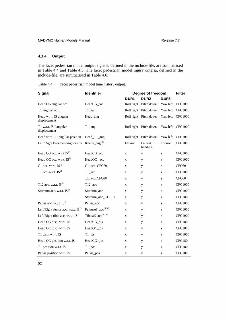
MADYMO Human Models Manual Release 7.7
52
4.3.4 Output
The facet pedestrian model output signals, defined in the include-file, are summarised
in Table 4.4 and Table 4.5. The facet pedestrian model injury criteria, defined in the
include-file, are summarised in Table 4.6.
Table 4.4 Facet pedestrian model time history output.
Signal Identifier Degree of freedom Filter
D1/R1 D1/R2 D1/R3
Head CG angular acc. HeadCG_aac Roll right Pitch down Yaw left CFC1000
T1 angular acc. T1_aac Roll right Pitch down Yaw left CFC1000
Head w.r.t. IS angular displacement
Head_ang Roll right Pitch down Yaw left CFC1000
T1 w.r.t. IS1) angular displacement
T1_ang Roll right Pitch down Yaw left CFC1000
Head w.r.t. T1 angular position Head_T1_ang Roll right Pitch down Yaw left CFC1000
Left/Right knee bending/torsion KneeS_ang10) Flexion Lateral bending
Torsion CFC1000
Head CG acc. w.r.t IS2) HeadCG_acc x y z CFC1000
Head OC acc. w.r.t. IS2) HeadOC_ acc x y z CFC1000
C1 acc. w.r.t. IS2) C1_acc_CFC60 x y z CFC60
T1 acc. w.r.t. IS2) T1_acc x y z CFC1000
T1_acc_CFC60 x y z CFC60
T12 acc. w.r.t. IS2) T12_acc x y z CFC1000
Sternum acc. w.r.t. IS2) Sternum_acc x y z CFC1000
Sternum_acc_CFC180 x y z CFC180
Pelvis acc. w.r.t. IS2) Pelvis_acc x y z CFC1000
Left/Right femur acc. w.r.t. IS2) FemurnS_acc 3,10) x y z CFC1000
Left/Right tibia acc. w.r.t. IS2) TibianS_acc 3,10) x y z CFC1000
Head CG disp. w.r.t. IS HeadCG_dis x y z CFC180
Head OC disp. w.r.t. IS HeadOC_dis x y z CFC1000
T1 disp. w.r.t. IS T1_dis x y z CFC1000
Head CG position w.r.t. IS HeadCG_pos x y z CFC180
T1 position w.r.t. IS T1_pos x y z CFC180
Pelvis position w.r.t. IS Pelvis_pos x y z CFC180
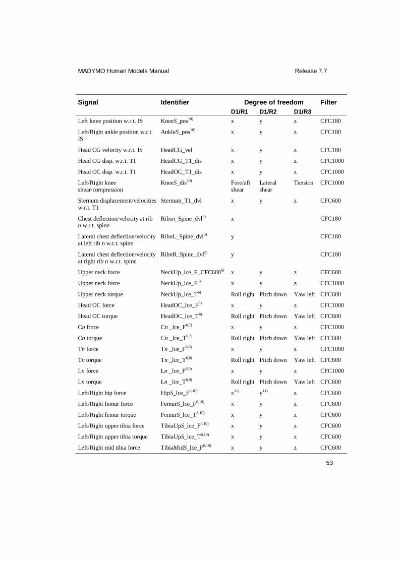
MADYMO Human Models Manual Release 7.7
53
Signal Identifier Degree of freedom Filter
D1/R1 D1/R2 D1/R3
Left knee position w.r.t. IS KneeS_pos10) x y z CFC180
Left/Right ankle position w.r.t. IS
AnkleS_pos10) x y z CFC180
Head CG velocity w.r.t. IS HeadCG_vel x y z CFC180
Head CG disp. w.r.t. T1 HeadCG_T1_dis x y z CFC1000
Head OC disp. w.r.t. T1 HeadOC_T1_dis x y z CFC1000
Left/Right knee shear/compression
KneeS_dis10) Fore/aft shear
Lateral shear
Tension CFC1000
Sternum displacement/velocities w.r.t. T1
Sternum_T1_dvl x y z CFC600
Chest deflection/velocity at rib n w.r.t. spine
Ribsn_Spine_dvl4) x CFC180
Lateral chest deflection/velocity at left rib n w.r.t. spine
RibnL_Spine_dvl5) y CFC180
Lateral chest deflection/velocity at right rib n w.r.t. spine
RibnR_Spine_dvl5) y CFC180
Upper neck force NeckUp_lce_F_CFC6006) x y z CFC600
Upper neck force NeckUp_lce_F6) x y z CFC1000
Upper neck torque NeckUp_lce_T6) Roll right Pitch down Yaw left CFC600
Head OC force HeadOC_lce_F6) x y z CFC1000
Head OC torque HeadOC_lce_T6) Roll right Pitch down Yaw left CFC600
Cn force Cn _lce_F6,7) x y z CFC1000
Cn torque Cn _lce_T6,7) Roll right Pitch down Yaw left CFC600
Tn force Tn _lce_F6,8) x y z CFC1000
Tn torque Tn _lce_T6,8) Roll right Pitch down Yaw left CFC600
Ln force Ln _lce_F6,9) x y z CFC1000
Ln torque Ln _lce_T6,9) Roll right Pitch down Yaw left CFC600
Left/Right hip force HipS_lce_F6,10) x11) y11) z CFC600
Left/Right femur force FemurS_lce_F6,10) x y z CFC600
Left/Right femur torque FemurS_lce_T6,10) x y z CFC600
Left/Right upper tibia force TibiaUpS_lce_F6,10) x y z CFC600
Left/Right upper tibia torque TibiaUpS_lce_T6,10) x y z CFC600
Left/Right mid tibia force TibiaMidS_lce_F6,10) x y z CFC600
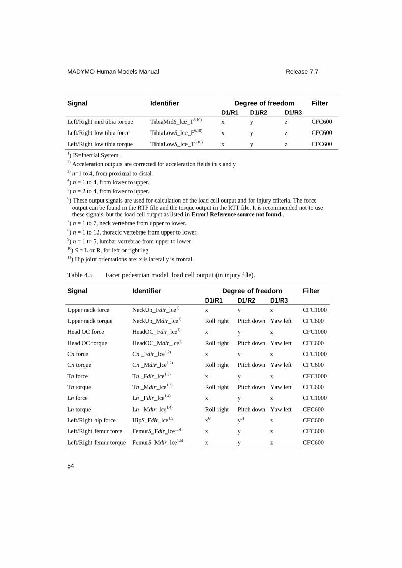
MADYMO Human Models Manual Release 7.7
54
Signal Identifier Degree of freedom Filter
D1/R1 D1/R2 D1/R3
Left/Right mid tibia torque TibiaMidS_lce_T6,10) x y z CFC600
Left/Right low tibia force TibiaLowS_lce_F6,10) x y z CFC600
Left/Right low tibia torque TibiaLowS_lce_T6,10) x y z CFC600
1) IS=Inertial System 2) Acceleration outputs are corrected for acceleration fields in x and y 3) n=1 to 4, from proximal to distal. 4) n = 1 to 4, from lower to upper. 5) n = 2 to 4, from lower to upper. 6) These output signals are used for calculation of the load cell output and for injury criteria. The force
output can be found in the RTF file and the torque output in the RTT file. It is recommended not to use these signals, but the load cell output as listed in Error! Reference source not found..
7) n = 1 to 7, neck vertebrae from upper to lower. 8) n = 1 to 12, thoracic vertebrae from upper to lower. 9) n = 1 to 5, lumbar vertebrae from upper to lower. 10) S = L or R, for left or right leg. 11) Hip joint orientations are: x is lateral y is frontal.
Table 4.5 Facet pedestrian model load cell output (in injury file).
Signal Identifier Degree of freedom Filter
D1/R1 D1/R2 D1/R3
Upper neck force NeckUp_Fdir_lce1) x y z CFC1000
Upper neck torque NeckUp_Mdir_lce1) Roll right Pitch down Yaw left CFC600
Head OC force HeadOC_Fdir_lce1) x y z CFC1000
Head OC torque HeadOC_Mdir_lce1) Roll right Pitch down Yaw left CFC600
Cn force Cn _Fdir_lce1,2) x y z CFC1000
Cn torque Cn _Mdir_lce1,2) Roll right Pitch down Yaw left CFC600
Tn force Tn _Fdir_lce1,3) x y z CFC1000
Tn torque Tn _Mdir_lce1,3) Roll right Pitch down Yaw left CFC600
Ln force Ln _Fdir_lce1,4) x y z CFC1000
Ln torque Ln _Mdir_lce1,4) Roll right Pitch down Yaw left CFC600
Left/Right hip force HipS_Fdir_lce1,5) x6) y6) z CFC600
Left/Right femur force FemurS_Fdir_lce1,5) x y z CFC600
Left/Right femur torque FemurS_Mdir_lce1,5) x y z CFC600
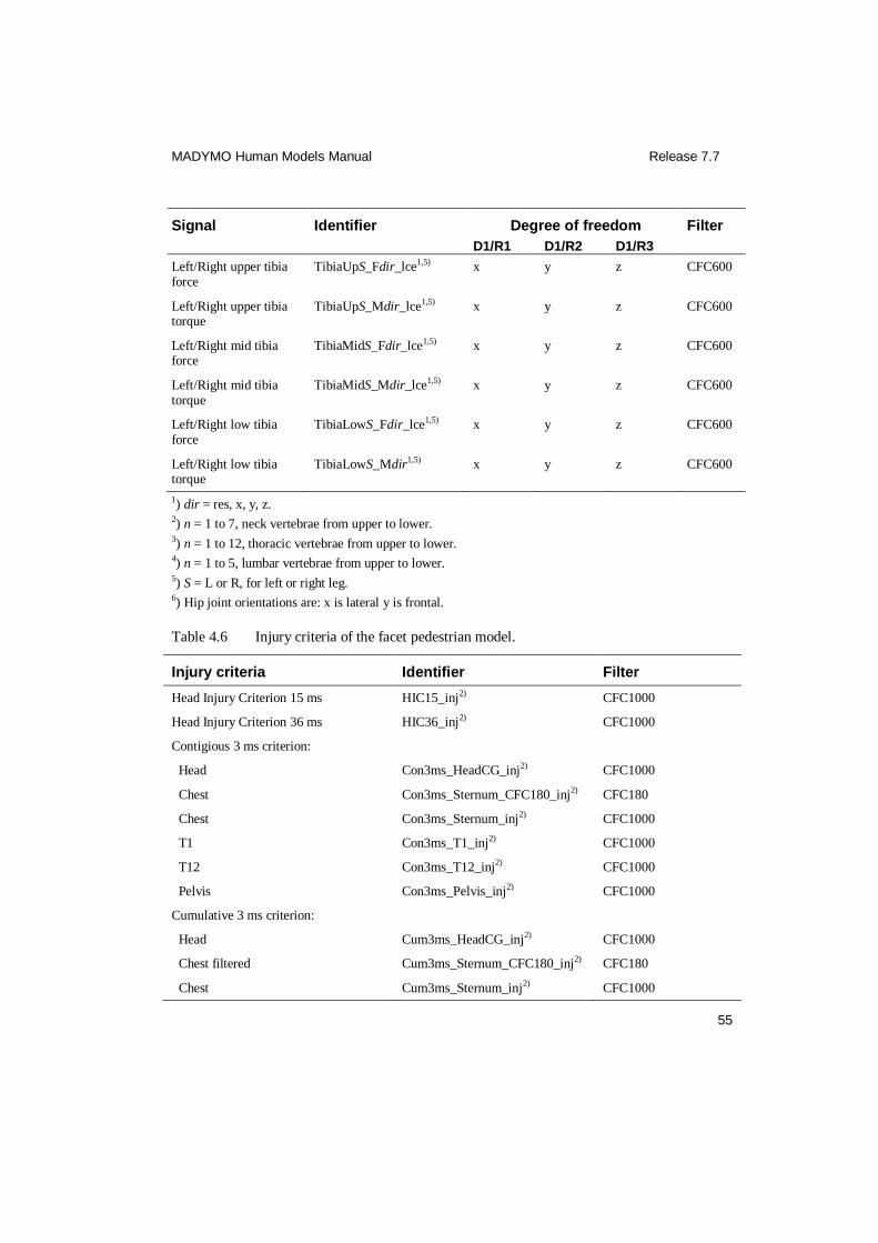
MADYMO Human Models Manual Release 7.7
55
Signal Identifier Degree of freedom Filter
D1/R1 D1/R2 D1/R3
Left/Right upper tibia force
TibiaUpS_Fdir_lce1,5) x y z CFC600
Left/Right upper tibia torque
TibiaUpS_Mdir_lce1,5) x y z CFC600
Left/Right mid tibia force
TibiaMidS_Fdir_lce1,5) x y z CFC600
Left/Right mid tibia torque
TibiaMidS_Mdir_lce1,5) x y z CFC600
Left/Right low tibia force
TibiaLowS_Fdir_lce1,5) x y z CFC600
Left/Right low tibia torque
TibiaLowS_Mdir1,5) x y z CFC600
1) dir = res, x, y, z. 2) n = 1 to 7, neck vertebrae from upper to lower. 3) n = 1 to 12, thoracic vertebrae from upper to lower. 4) n = 1 to 5, lumbar vertebrae from upper to lower. 5) S = L or R, for left or right leg. 6) Hip joint orientations are: x is lateral y is frontal.
Table 4.6 Injury criteria of the facet pedestrian model.
Injury criteria Identifier Filter
Head Injury Criterion 15 ms HIC15_inj2) CFC1000
Head Injury Criterion 36 ms HIC36_inj2) CFC1000
Contigious 3 ms criterion:
Head Con3ms_HeadCG_inj2) CFC1000
Chest Con3ms_Sternum_CFC180_inj2) CFC180
Chest Con3ms_Sternum_inj2) CFC1000
T1 Con3ms_T1_inj2) CFC1000
T12 Con3ms_T12_inj2) CFC1000
Pelvis Con3ms_Pelvis_inj2) CFC1000
Cumulative 3 ms criterion:
Head Cum3ms_HeadCG_inj2) CFC1000
Chest filtered Cum3ms_Sternum_CFC180_inj2) CFC180
Chest Cum3ms_Sternum_inj2) CFC1000

MADYMO Human Models Manual Release 7.7
56
Injury criteria Identifier Filter
T1 Cum3ms_T1_inj2) CFC1000
T12 Cum3ms_T12_inj2) CFC1000
Pelvis Cum3ms_Pelvis_inj2) CFC1000
Viscous Injury Response Criterion for rib layer n
VCRibsn_inj1,2,3) CFC180
Lateral Viscous Injury Response Criterion for left rib layer n
VCRibnL_inj1,2,4) CFC180
Lateral Viscous Injury Response Criterion for right rib layer n
VCRibnR_inj1,2,4) CFC180
Neck NIC Forward:
Tension FNICTension_inj1) CFC1000
Shear FNICShear_inj1) CFC1000
Bending FNICBending_inj1) CFC1000 (force) CFC600 (torque)
Neck NIC Rearward: NIC_rearward_C1_T11,2) CFC60
Neck combined injury criteria:
Nij Tension-extension NTE_inj1,2) CFC600 (force) CFC600 (torque)
Nij Tension-flexion NTF_inj1,2) CFC600 (force) CFC600 (torque)
Nij Compression-extension NCE_inj1,2) CFC600 (force) CFC600 (torque)
Nij Compression-flexion NCF_inj1,2) CFC600 (force) CFC600 (torque)
Nkm Flexion-anterior NFA_inj1,2) CFC600 (force) CFC600 (torque)
Nkm Extension-anterior NEA_inj1,2) CFC600 (force) CFC600 (torque)
Nkm Flexion-posterior NFP_inj1,2) CFC600 (force) CFC600 (torque)
Nkm Extension-posterior NEP_inj1,2) CFC600 (force) CFC600 (torque)
Combined Thoracic Index CTI_inj2)
Left Femur Force Criterion FFCL_inj1) CFC600
Right Femur Force Criterion FFCR_inj1) CFC600
1) This injury output can be found in the INJURY file.

MADYMO Human Models Manual Release 7.7
57
2) The injury output can be found in the PEAK file. 3) n = 1 to 4, from lower to upper. 4) n = 2 to 4, from lower to upper.
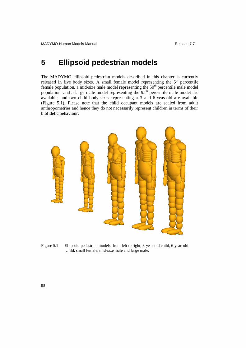
MADYMO Human Models Manual Release 7.7
58
5 Ellipsoid pedestrian models
The MADYMO ellipsoid pedestrian models described in this chapter is currently
released in five body sizes. A small female model representing the 5th percentile
female population, a mid-size male model representing the 50th
percentile male model
population, and a large male model representing the 95th percentile male model are
available, and two child body sizes representing a 3 and 6-yeas-old are available (Figure 5.1). Please note that the child occupant models are scaled from adult
anthropometries and hence they do not necessarily represent children in terms of their
biofidelic behaviour.
Figure 5.1 Ellipsoid pedestrian models, from left to right; 3-year-old child, 6-year-old
child, small female, mid-size male and large male.
MADYMO Human Models Manual Release 7.7
59
5.1 Model description
The MADYMO model names and input file names of the ellipsoid pedestrian models are:
3-year-old child: h_ped3yel_usr.xml
h_ped3yel_inc.xml
6-year-old child: h_ped6yel_usr.xml h_ped6yel_inc.xml
Small female: h_ped05el_usr.xml
h_ped05el_inc.xml
Mid-size male: h_ped50el_usr.xml
h_ped50el_inc.xml
Large male: h_ped95el_usr.xml h_ped95el_inc.xml
Besides these models, a scaleable pedestrian model is available:
Parameter model mid size male: h_ped50el.par
Using the MADYMO/SCALER utility, this model can be scaled towards different anthropometry data sets.
5.1.1 Anthropometry
The mid-size male pedestrian model was developed first. The anthropometry of this model was, similar to the facet occupant models, based on the database of the
RAMSIS software package (RAMSIS, 1997). Like for the facet occupant models, the
Western European population aged 18-70 years in 1984 has been used. Afterwards, the mid-size male pedestrian model has been scaled towards a 3-year-old child, a 6-
year-old child, a small female and a large male model (see Figure 5.1). The
anthropometries of the small female and large male pedestrian models were also
based on the RAMSIS database. The anthropometries of the 3- and 6-year-old child were based on the specification of the Q child dummies. Global anthropometry
specifications are given in Table 5.1.

MADYMO Human Models Manual Release 7.7
60
Table 5.1 Anthropometry of the ellipsoid pedestrian models.
Parameter 3 year old child
6 year old child
Small female
Mid-size male
Large male
Standing height [m] 0.95 1.17 1.53 1.74 1.91
Seated height [m] 0.55 0.64 0.81 0.92 1.00
Shoulder breadth [m] 0.25 0.28 0.40 0.47 0.52
Knee height [m] 0.28 0.35 0.47 0.54 0.59
Weight [kg] 14.5 23.0 49.77 75.7 101.1
The scaling of the pedestrian models was done using MADYMO/SCALER (Happee
et al., 1998). In MADYMO/SCALER different scaling factors are specified for x-, y-,
and z-dimensions and for different body parts. Thus the model geometry can be
adapted freely to the desired anthropometry parameters. In addition to the geometry, all other model parameters can be scaled. Based on the desired anthropometry
parameters there is scaling of:
Geometry
Mass and moments of Inertia
Joint characteristics (stiffness, friction, damping and hysteresis), including that of
protected joints
Ellipsoids and penetration characteristics
Force models
Fracture levels
Sensor locations
5.1.2 Configuration
The pedestrian models each consist of 52 rigid bodies, organised in 7 configuration
branches. The outer surface is described by 64 ellipsoids and 2 planes. The first branch connects the head and thorax to the pelvis. The second and third branch
connect the bodies of the left and right arm to T1, respectively. The fourth and fifth
branch connect the bodies of the left and right leg to the pelvis, respectively. The
heels are each connected to the mid-foot joint by a separate branch.

MADYMO Human Models Manual Release 7.7
61
5.1.3 Spine and neck
The spine and neck are modelled by 4 kinematic joints. The spine consists of 1
spherical joint at lumbar location and 1 free joint at thoracic location. The neck is
modelled by 2 free joints at the lower neck location (T1-C7) and 1 at the upper neck (C1-Head OC) location, respectively. The free joints in the spine and neck allow
elongation. The stiffness in the different directions is modelled by six-DOF restraints
at the joint locations. The rotational stiffnesses in the spine are based on Yang et al.
(2000). The translational stiffness in the z-direction is based on the resultant elongation stiffness of the facet occupant models. The translational stiffnesses in x-
and y-direction are higher than in z-direction, in order to prevent lateral translation. In
the z-direction also damping coefficients are added, which are also based on the facet occupant models.
5.1.4 Thorax and abdomen
For application in contact with vehicle models, it was considered desirable to represent each torso section (pelvis, abdomen, ribs, shoulder and for female also
breasts) by just one ellipsoid of sufficient size. The ellipsoids are sufficiently large to
avoid unrealistic discontinuities, when ellipsoids contact the edges of vehicle parts,
like the bonnet leading edge. In defining the ellipsoids it was already taken into account that scaled pedestrian models should also interact realistically with vehicle
models. Using few ellipsoids also diminishes the chance on multiple contacts with
one vehicle part. When using combined contact functions, multiple contacts with one vehicle part lead to a too high resultant stiffness.
Contact characteristics have been implemented for lateral loading of pelvis, abdomen,
ribs and shoulder. The contact characteristics (stiffness, hysteresis, damping) were
based on data found in literature and optimized in simulations of a large range of PMHS impactor tests on various body parts, see Section 5.2. Based on various pelvis
impactor simulations, different contact stiffness characteristics were used for the
lateral and rear part of the pelvis to represent the difference in the amount of flesh in these areas.
5.1.5 Hip
The hip joint is modelled by a spherical joint. The joint stiffness curves were taken from the validated pedestrian model by Yang & Lovsund (1997) who selected the hip
resistance after Frankel & Nordin (1980). The joint stiffness curves were found to
agree well with ranges of motion of the RAMSIS human model (Speyer and Seidl,
1997).
MADYMO Human Models Manual Release 7.7
62
5.1.6 Knee
The knee is a complex joint with a strong coupling between the degrees of freedom.
The resistance for axial rotation is, for instance, dependent on the knee flexion angle.
In principle, geometric modelling of the relevant joint surface interactions and ligaments, muscles, and other soft tissues allows the definition of a general knee
model. However, detailed knee models for impact are still restricted in their range of
application. Therefore, the pedestrian knee is modelled by just one free joint and the
knee model characteristics have been optimized for an approximately extended position, as this position is most relevant for pedestrian loading. Linear and non-linear
joint resistance functions have been implemented in accordance with available data
from literature.
Linear lateral bending stiffness matching the dynamic data of Kajzer et al. (1997) has
been implemented, which is significantly larger than quasi-static values reported by
Piziali & Rastegar (1977) and Markolf et al. (1976), but comparable to EEVC requirements (EEVC, 1994). The knee flexion/extension stiffness has been
implemented using volunteer data (Engin, 1979a; Ma et al. 1995). Inward rotation of
the foot with respect to the femur has been implemented as a combination of knee and
ankle joint rotation. Using data from Engin (1979b) for both joints an identical resistance has been implemented for axial rotation.
For knee lateral shear the EEVC (1994, 1998a) has defined an injury tolerance level
of 4 kN force and 6 mm displacement. This results in a linear stiffness of 6.7E5 N/m, which has been applied in the pedestrian model. For pedestrian applications,
forward/rearward shear is considered of minor importance and therefore the stiffness
selected for lateral shear has also been applied for forward/rearward shear. Results
from Piziali & Rastegar (1977) indicate that this is acceptable for conditions with an extended knee. A linear stiffness was implemented for knee axial compression based
on the initial displacement (1 mm) of PMHS data of Walker & Hajek (1972).
5.1.7 Upper and lower leg
In pedestrian impacts, leg bending and resulting bone fracture is commonly found. To
account for this in the pedestrian model, bending and fracture properties were
implemented at several locations in the femur and tibia using bending/fracture joints. In both the upper and lower leg spherical joints have been implemented in order to
model bending and fracture. In Figure 5.2 all joint locations in the leg are specified:
the large spots show the hip, knee and ankle joints, the small spots show the locations
of the bending and/or fracture joints. The location of the middle bending joint in the femur corresponds with the location of the femur loadcell in the Hybrid III dummy.
The locations of the upper and lower bending joints in the tibia correspond with the
locations of the tibia loadcells in the Hybrid III dummy.
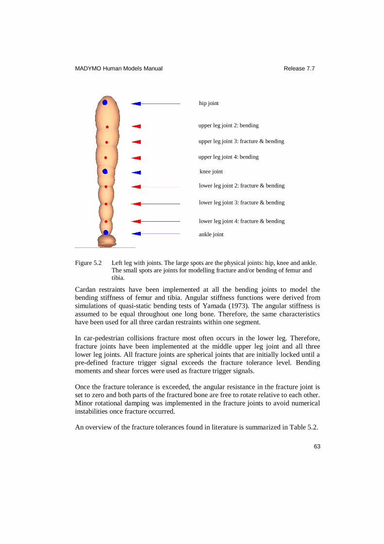
MADYMO Human Models Manual Release 7.7
63
Figure 5.2 Left leg with joints. The large spots are the physical joints: hip, knee and ankle.
The small spots are joints for modelling fracture and/or bending of femur and
tibia.
Cardan restraints have been implemented at all the bending joints to model the bending stiffness of femur and tibia. Angular stiffness functions were derived from
simulations of quasi-static bending tests of Yamada (1973). The angular stiffness is
assumed to be equal throughout one long bone. Therefore, the same characteristics have been used for all three cardan restraints within one segment.
In car-pedestrian collisions fracture most often occurs in the lower leg. Therefore,
fracture joints have been implemented at the middle upper leg joint and all three
lower leg joints. All fracture joints are spherical joints that are initially locked until a pre-defined fracture trigger signal exceeds the fracture tolerance level. Bending
moments and shear forces were used as fracture trigger signals.
Once the fracture tolerance is exceeded, the angular resistance in the fracture joint is set to zero and both parts of the fractured bone are free to rotate relative to each other.
Minor rotational damping was implemented in the fracture joints to avoid numerical
instabilities once fracture occurred.
An overview of the fracture tolerances found in literature is summarized in Table 5.2.
knee joint
lower leg joint 4: fracture & bending
lower leg joint 3: fracture & bending
lower leg joint 2: fracture & bending
hip joint
upper leg joint 3: fracture & bending
ankle joint
upper leg joint 2: bending
upper leg joint 4: bending
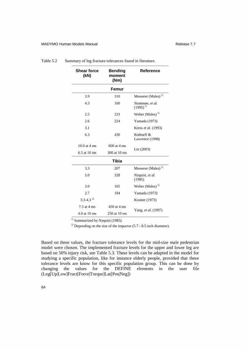
MADYMO Human Models Manual Release 7.7
64
Table 5.2 Summary of leg fracture tolerances found in literature.
Shear force (kN)
Bending moment
(Nm)
Reference
Femur
3.9 310 Messerer (Males) 1)
4.3 160 Strømsøe, et al. (1995) 1)
2.5 233 Weber (Males) 1)
2.6 224 Yamada (1973)
3.1 Kress et al. (1993)
6.3 430 Rodmell & Lawrence (1998)
10.0 at 4 ms 600 at 4 ms Liu (2003)
6.5 at 10 ms 300 at 10 ms
Tibia
3.3 207 Messerer (Males) 1)
5.0 328 Nyquist, et al. (1985)
3.0 165 Weber (Males) 1)
2.7 194 Yamada (1973)
3.3-4.3 2) Kramer (1973)
7.5 at 4 ms 450 at 4 ms Yang, et al. (1997)
4.0 at 10 ms 250 at 10 ms
1) Summarized by Nyquist (1985).
2) Depending on the size of the impactor (5.7 - 8.5 inch diameter).
Based on these values, the fracture tolerance levels for the mid-size male pedestrian model were chosen. The implemented fracture levels for the upper and lower leg are
based on 50% injury risk, see Table 5.3. These levels can be adapted in the model for
studying a specific population, like for instance elderly people, provided that these
tolerance levels are know for this specific population group. This can be done by changing the values for the DEFINE elements in the user file
(Leg[Up|Low]Fract[Force|Torque]Lat[Pos|Neg])

MADYMO Human Models Manual Release 7.7
65
Table 5.3 Fracture levels for the upper and lower leg, based on 50% injury risk.
Model part Torque [Nm] Reference Shear force [N]
Reference
3-year-old child:
Upper leg 55 scaled 1560 Scaled
Lower leg 50 scaled 1040 Scaled
6-year-old child:
Upper leg 140 scaled 2840 Scaled
Lower leg 85 scaled 1890 Scaled
Small female:
Upper leg 265 scaled 4390 Scaled
Lower leg 240 scaled 2925 Scaled
Mid-size male:
Upper leg 430 EEVC WG17 6000 Based on EEVC WG17
Lower leg 285 Nyquist et al. (1985) 4000 Yang et al. (2000)
Large male:
Upper leg 575 scaled 7285 Scaled
Lower leg 435 scaled 4855 Scaled
5.1.8 Ankle, foot and shoe
For the ankle and foot a MADYMO model of the ‘soft stop foot’ of the Hybrid III is
adopted. In this model the shoes of the Hybrid III have been added as separate bodies
allowing some relative motion between feet and shoes. The shoe model is also
included in the pedestrian model.
Since the ankle rotation stiffness of the Hybrid III is still not biofidelic and
mechanical failure has been observed (Crandall et al., 1996), the ankle joint resistance
parameters of the pedestrian model were adapted using biomechanical data. In volunteer and PMHS experiments the ankle dorsiflexion stiffness is found to depend
on the knee flexion angle. The rotational stiffness for ankle dorsiflexion was derived
from volunteer tests with extended knees (Crandall et al., 1996). The rotational
stiffness for inversion/eversion was also derived from volunteer data (Crandall et al., 1996). Inward rotation of the foot has been implemented as a combination of knee
and ankle rotation using data from Engin (1979b).

MADYMO Human Models Manual Release 7.7
66
5.2 Model validation
The human pedestrian model has been validated extensively. First, one series of leg shear and bending tests has been used (Kajzer, 1997). The contact characteristics
(stiffness, hysteresis, damping) with the various other body parts have been based on
data found in literature and optimized in simulations of a large range of PMHS
impactor tests on various body parts. Furthermore, three different sets of PMHS pedestrian-vehicle impact tests have been simulated to verify the biofidelity of the
pedestrian model. An overview of the validation is described below. An extended
description of the validation simulations and results can be found in Hoof et al. (2003). The implementation of a typical car-pedestrian test is described in the
‘examples’ section.
From the extended validation of the pedestrian models it can be concluded that:
The models accurately predict the global kinematics.
The models accurately predict the impact points on the vehicle, especially for
the head.
The models can reasonably predict the occurrence of fractures in the upper
and lower legs during the impact between the pedestrian and the vehicle.
The models can predict the shape and trends of the head, chest and pelvis
accelerations and the bumper forces.
5.2.1 Blunt impact tests
The blunt impact tests used for the validation of the pedestrian models are
summarised in Table 5.4. The different impactor test configurations simulated are
presented in Figure 5.3.
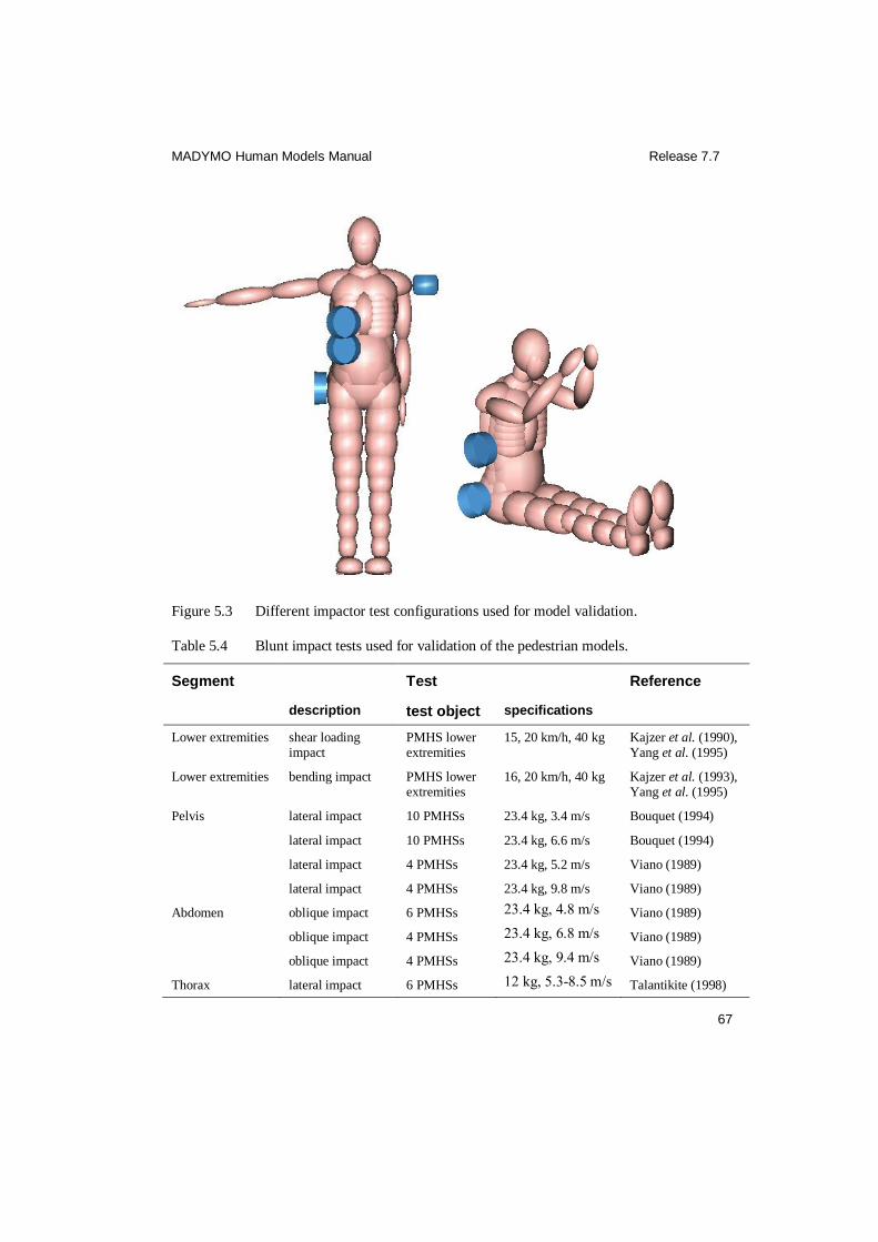
MADYMO Human Models Manual Release 7.7
67
Figure 5.3 Different impactor test configurations used for model validation.
Table 5.4 Blunt impact tests used for validation of the pedestrian models.
Segment Test Reference
description test object specifications
Lower extremities shear loading impact
PMHS lower extremities
15, 20 km/h, 40 kg Kajzer et al. (1990), Yang et al. (1995)
Lower extremities bending impact PMHS lower extremities
16, 20 km/h, 40 kg Kajzer et al. (1993), Yang et al. (1995)
Pelvis lateral impact 10 PMHSs 23.4 kg, 3.4 m/s Bouquet (1994)
lateral impact 10 PMHSs 23.4 kg, 6.6 m/s Bouquet (1994)
lateral impact 4 PMHSs 23.4 kg, 5.2 m/s Viano (1989)
lateral impact 4 PMHSs 23.4 kg, 9.8 m/s Viano (1989)
Abdomen oblique impact 6 PMHSs 23.4 kg, 4.8 m/s Viano (1989)
oblique impact 4 PMHSs 23.4 kg, 6.8 m/s Viano (1989)
oblique impact 4 PMHSs 23.4 kg, 9.4 m/s Viano (1989)
Thorax lateral impact 6 PMHSs 12 kg, 5.3-8.5 m/s Talantikite (1998)
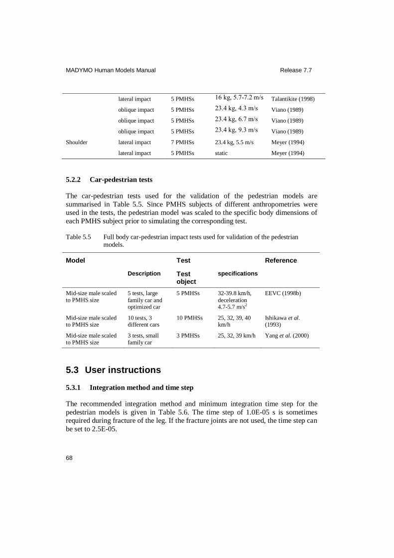
MADYMO Human Models Manual Release 7.7
68
lateral impact 5 PMHSs 16 kg, 5.7-7.2 m/s Talantikite (1998)
oblique impact 5 PMHSs 23.4 kg, 4.3 m/s Viano (1989)
oblique impact 5 PMHSs 23.4 kg, 6.7 m/s Viano (1989)
oblique impact 5 PMHSs 23.4 kg, 9.3 m/s Viano (1989)
Shoulder lateral impact 7 PMHSs 23.4 kg, 5.5 m/s Meyer (1994)
lateral impact 5 PMHSs static Meyer (1994)
5.2.2 Car-pedestrian tests
The car-pedestrian tests used for the validation of the pedestrian models are
summarised in Table 5.5. Since PMHS subjects of different anthropometries were used in the tests, the pedestrian model was scaled to the specific body dimensions of
each PMHS subject prior to simulating the corresponding test.
Table 5.5 Full body car-pedestrian impact tests used for validation of the pedestrian
models.
Model Test Reference
Description Test object
specifications
Mid-size male scaled to PMHS size
5 tests, large
family car and optimized car
5 PMHSs 32-39.8 km/h,
deceleration 4.7-5.7 m/s2
EEVC (1998b)
Mid-size male scaled to PMHS size
10 tests, 3 different cars
10 PMHSs 25, 32, 39, 40 km/h
Ishikawa et al. (1993)
Mid-size male scaled to PMHS size
3 tests, small family car
3 PMHSs 25, 32, 39 km/h Yang et al. (2000)
5.3 User instructions
5.3.1 Integration method and time step
The recommended integration method and minimum integration time step for the
pedestrian models is given in Table 5.6. The time step of 1.0E-05 s is sometimes required during fracture of the leg. If the fracture joints are not used, the time step can
be set to 2.5E-05.

MADYMO Human Models Manual Release 7.7
69
Table 5.6 Recommended integration method and time step for the pedestrian models.
Model Integration method Time step (s)
3-year-old child EULER ≤1.0E-05
6-year-old child EULER ≤1.0E-05
Small female EULER ≤1.0E-05
Mid-size male EULER ≤1.0E-05
Large male EULER ≤1.0E-05
5.3.2 Positioning
Positioning of the pedestrian model in MADYMO is done in three steps:
1. The complete pedestrian model is positioned and orientated correctly with respect
to its environment by initialising the position and orientation of the human joint (‘Human_jnt’), which is a free joint connecting the pedestrian model to its
environment. The pedestrian model must be placed at a position such that the
shoes touch the ground.
2. The extremities and other pedestrian model segments are orientated with respect
to the parent segment by changing the orientation of the corresponding bodies in
the positioning element (JOINT_DOF). The pedestrian model can for example be
put in a walking position.
3. Contact has to be defined between the pedestrian shoes and the ground. An
equilibrium between the gravitational force and the ground contact force acting
on the pedestrian model will have to be obtained. This can be done by performing short simulations the pedestrian in a gravitational field and change the initial
position of the Human_jnt, until the pedestrian stands still.
When all joints in INITIAL.JOINT_POS are set to zero (except for the ankles), the pedestrian model is in an erect standing position as is shown in Figure 5.4. This
position is called the reference position. In this position the joint translations and
rotations are defined as shown in Figure 5.4.
The orientations of the translational (D) and rotational (R) DOF of the pedestrian model positioning joints are given in Table 5.7. The positioning joints are
schematically drawn in Figure 5.5.
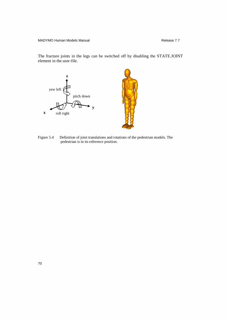
MADYMO Human Models Manual Release 7.7
70
The fracture joints in the legs can be switched off by disabling the STATE.JOINT element in the user-file.
Figure 5.4 Definition of joint translations and rotations of the pedestrian models. The pedestrian is in its reference position.
x
y
z
roll right
pitch down
yaw left

MADYMO Human Models Manual Release 7.7
71
Figure 5.5 Locations of the positioning joints of the pedestrian model.
Shoulder
Elbow
NeckUp-Head
LumbarUp-TorsoUp
Human joint Hip
Wrist
Knee
Ankle
LumbarLow-LumbarUp
TorsoUp-NeckLow NeckLow-NeckUp

MADYMO Human Models Manual Release 7.7
72
Table 5.7 Positioning joints of the pedestrian models.
Joint description
Identifier Degree of freedom
D1 / R1 D2 / R2 D3 / R3
Complete human Human_jnt X / Roll right Y / Pitch down Z / Yaw left
Lower lumbar joint LumbarLow-LumbarUp_jnt Yaw right Pitch down Roll right
Upper lumbar joint LumbarUp-TorsoUp_jnt Roll right Pitch down Yaw left
T1 TorsoUp-NeckLow_jnt Pitch down
Neck joint NeckLow-NeckUp_jnt Roll right Pitch down Yaw left
Head OC NeckUp-Head_jnt Roll right Pitch down Yaw left
Hip HipS_jnt Roll right Pitch down Yaw left
Knee KneeS_jnt1) Pitch down Roll left Yaw left
Ankle AnkleS_jnt Yaw left Roll right Pitch down
Shoulder ShoulderS_jnt Pitch down Roll right
Elbow ElbowS_jnt Yaw left Pitch down
Wrist WristS_jnt Yaw left Roll right
1) S = L or R, stands for left and right side, respectively.
5.3.3 Contacts
The available contact groups (in the include-file) that can be used to define contact
between the pedestrian and its environment in the user-file are summarised in Table
5.8.
Since a lot of ellipsoids are defined for the legs and the thorax, it is very important to
carefully choose the contact between the ellipsoids of the pedestrian and the
contacting surface of the vehicle or the road.
It is recommended to very carefully use the EVALUATIONS option for ellipsoid-
ellipsoid contact. If this option is used, the complete contact force can switch from
one ellipsoid to another and back depending on the ellipsoid that is most penetrated.
With this switching of the contact force, large unrealistic vibrations can be introduced.
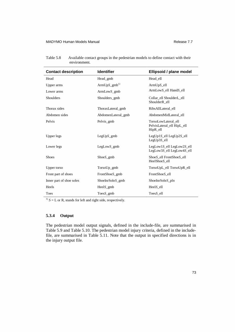
MADYMO Human Models Manual Release 7.7
73
Table 5.8 Available contact groups in the pedestrian models to define contact with their
environment.
Contact description Identifier Ellipsoid / plane model
Head Head_gmb Head_ell
Upper arms ArmUpS_gmb1) ArmUpS_ell
Lower arms ArmLowS_gmb ArmLowS_ell HandS_ell
Shoulders Shoulders_gmb Collar_ell ShoulderL_ell ShoulderR_ell
Thorax sides ThoraxLateral_gmb RibsAllLateral_ell
Abdomen sides AbdomenLateral_gmb AbdomenMidLateral_ell
Pelvis Pelvis_gmb TorsoLowLateral_ell
PelvisLateral_ell HipL_ell HipR_ell
Upper legs LegUpS_gmb LegUp1S_ell LegUp2S_ell LegUp3S_ell
Lower legs LegLowS_gmb LegLow1S_ell LegLow2S_ell LegLow3S_ell LegLow4S_ell
Shoes ShoeS_gmb ShoeS_ell FrontShoeS_ell HeelShoeS_ell
Upper torso TorsoUp_gmb TorsoUpL_ell TorsoUpR_ell
Front part of shoes FrontShoeS_gmb FrontShoeS_ell
Inner part of shoe soles ShoeInrSoleS_gmb ShoeInrSoleS_pln
Heels HeelS_gmb HeelS_ell
Toes ToesS_gmb ToesS_ell
1) S = L or R, stands for left and right side, respectively.
5.3.4 Output
The pedestrian model output signals, defined in the include-file, are summarised in
Table 5.9 and Table 5.10. The pedestrian model injury criteria, defined in the include-
file, are summarised in Table 5.11. Note that the output in specified directions is in the injury output file.
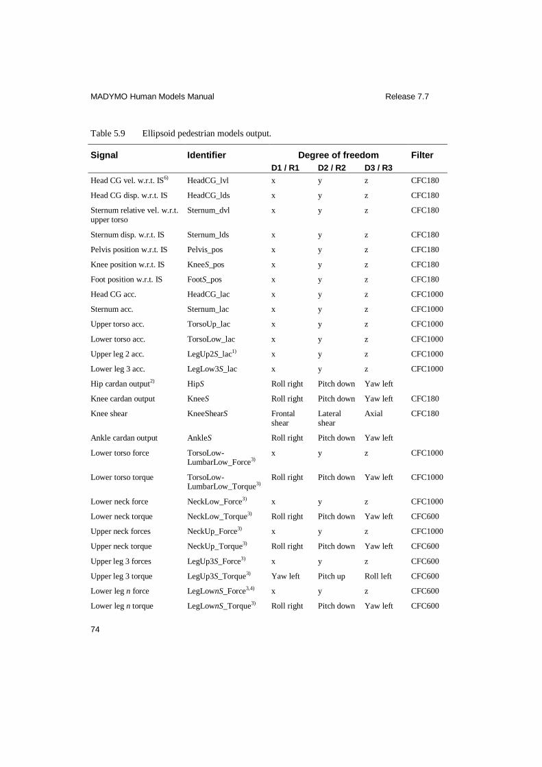
MADYMO Human Models Manual Release 7.7
74
Table 5.9 Ellipsoid pedestrian models output.
Signal Identifier Degree of freedom Filter
D1 / R1 D2 / R2 D3 / R3
Head CG vel. w.r.t. IS6) HeadCG_lvl x y z CFC180
Head CG disp. w.r.t. IS HeadCG_lds x y z CFC180
Sternum relative vel. w.r.t. upper torso
Sternum_dvl x y z CFC180
Sternum disp. w.r.t. IS Sternum_lds x y z CFC180
Pelvis position w.r.t. IS Pelvis_pos x y z CFC180
Knee position w.r.t. IS KneeS_pos x y z CFC180
Foot position w.r.t. IS FootS_pos x y z CFC180
Head CG acc. HeadCG_lac x y z CFC1000
Sternum acc. Sternum_lac x y z CFC1000
Upper torso acc. TorsoUp_lac x y z CFC1000
Lower torso acc. TorsoLow_lac x y z CFC1000
Upper leg 2 acc. LegUp2S_lac1) x y z CFC1000
Lower leg 3 acc. LegLow3S_lac x y z CFC1000
Hip cardan output2) HipS Roll right Pitch down Yaw left
Knee cardan output KneeS Roll right Pitch down Yaw left CFC180
Knee shear KneeShearS Frontal shear
Lateral shear
Axial CFC180
Ankle cardan output AnkleS Roll right Pitch down Yaw left
Lower torso force TorsoLow-LumbarLow_Force3)
x y z CFC1000
Lower torso torque TorsoLow-LumbarLow_Torque3)
Roll right Pitch down Yaw left CFC1000
Lower neck force NeckLow_Force3) x y z CFC1000
Lower neck torque NeckLow_Torque3) Roll right Pitch down Yaw left CFC600
Upper neck forces NeckUp_Force3) x y z CFC1000
Upper neck torque NeckUp_Torque3) Roll right Pitch down Yaw left CFC600
Upper leg 3 forces LegUp3S_Force3) x y z CFC600
Upper leg 3 torque LegUp3S_Torque3) Yaw left Pitch up Roll left CFC600
Lower leg n force LegLownS_Force3,4) x y z CFC600
Lower leg n torque LegLownS_Torque3) Roll right Pitch down Yaw left CFC600

MADYMO Human Models Manual Release 7.7
75
Signal Identifier Degree of freedom Filter
D1 / R1 D2 / R2 D3 / R3
Upper leg 3 lateral torque5) LegUp3S_TorqueLat Yaw left Pitch up Roll left CFC600
Lower leg n lateral torque5) LegLownS_TorqueLat Roll right Pitch down Yaw left CFC600
Upper leg 3 lateral force5) LegUp3S_ForceLat x y z CFC600
Lower leg n lateral force5) LegLownS_ForceLat x y z CFC600
1) S = L or R, stands for left and right side, respectively. 2) Note that the cardan output is given in successive rotations. The cardan output can be found in the
CAN file. 3) These output signals are used for calculation of the neck, torso and leg output specified in directions.
The forces can be found in the FRC file, and the torques in the RTT file. It is recommended to use the specified neck, torso and leg output, see Table 5.10.
4) n = 2, 3 or 4, see Figure 5.2. 5) Used as trigger signals for the fracture joints 6) IS=Inertial System
Table 5.10 Pedestrian models load cell output of torso, lower and upper neck and legs in specified directions.
Signal Identifier Degree of freedom Filter
D1 / R1 D2 / R2 D3 / R3
Spec. lower torso force:
Resultant TorsoLow-LumbarLow_FRES
CFC 1000
For-rearward shear TorsoLow-LumbarLowFX_SHEAR
x CFC 1000
Lateral shear TorsoLow-LumbarLowFY_SHEAR
y CFC 1000
Axial TorsoLow-LumbarLowFZ_AXIAL
z CFC 1000
Spec. lower torso torque:
Resultant TorsoLow-LumbarLow_MRES
CFC 1000
Lateral TorsoLow-LumbarLowMX_ROLL
Roll right CFC 1000
For-rearward TorsoLow-LumbarLowMY_PITCH
Pitch down CFC 1000
Axial TorsoLow-LumbarLowMZ_YAW
Yaw left CFC 1000
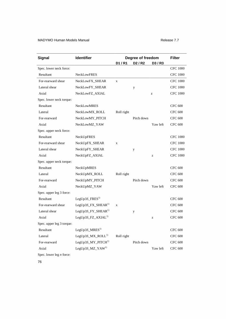
MADYMO Human Models Manual Release 7.7
76
Signal Identifier Degree of freedom Filter
D1 / R1 D2 / R2 D3 / R3
Spec. lower neck force: CFC 1000
Resultant NeckLowFRES CFC 1000
For-rearward shear NeckLowFX_SHEAR x CFC 1000
Lateral shear NeckLowFY_SHEAR y CFC 1000
Axial NeckLowFZ_AXIAL z CFC 1000
Spec. lower neck torque:
Resultant NeckLowMRES CFC 600
Lateral NeckLowMX_ROLL Roll right CFC 600
For-rearward NeckLowMY_PITCH Pitch down CFC 600
Axial NeckLowMZ_YAW Yaw left CFC 600
Spec. upper neck force:
Resultant NeckUpFRES CFC 1000
For-rearward shear NeckUpFX_SHEAR x CFC 1000
Lateral shear NeckUpFY_SHEAR y CFC 1000
Axial NeckUpFZ_AXIAL z CFC 1000
Spec. upper neck torque:
Resultant NeckUpMRES CFC 600
Lateral NeckUpMX_ROLL Roll right CFC 600
For-rearward NeckUpMY_PITCH Pitch down CFC 600
Axial NeckUpMZ_YAW Yaw left CFC 600
Spec. upper leg 3 force:
Resultant LegUp3S_FRES1) CFC 600
For-rearward shear LegUp3S_FX_SHEAR1) x CFC 600
Lateral shear LegUp3S_FY_SHEAR1) y CFC 600
Axial LegUp3S_FZ_AXIAL1) z CFC 600
Spec. upper leg 3 torque:
Resultant LegUp3S_MRES1) CFC 600
Lateral LegUp3S_MX_ROLL1) Roll right CFC 600
For-rearward LegUp3S_MY_PITCH1) Pitch down CFC 600
Axial LegUp3S_MZ_YAW1) Yaw left CFC 600
Spec. lower leg n force:

MADYMO Human Models Manual Release 7.7
77
Signal Identifier Degree of freedom Filter
D1 / R1 D2 / R2 D3 / R3
Resultant LegLownS_FRES1,2) CFC 600
For-rearward shear LegLownS_FX_SHEAR1,2) x CFC 600
Lateral shear LegLownS_FY_SHEAR1,2) y CFC 600
Axial LegLownS_FZ_AXIAL1,2) z CFC 600
Spec. lower leg n torque:
Resultant LegLownS_MRES1,2) CFC 600
Lateral LegLownS_MX_ROLL1,2) Roll right CFC 600
For-rearward LegLownS_MY_PITCH1,2) Pitch down CFC 600
Axial LegLownS_MZ_YAW1,2) Yaw left CFC 600
1) S = L or R, stands for left and right side, respectively. 2) n = 2, 3 or 4, see Figure 5.2.
Table 5.11 Injury criteria of the pedestrian models.
Injury criteria Identifier Filter
Head Injury Criterion 15 ms HIC_inj1) CFC1000
Contigious 3 ms criterion:
Head Con3msHeadCG_inj1) CFC1000
Torso Con3msTorsoUp_inj1) CFC1000
Cumulative 3 ms criterion:
Head Cum3msHeadCG_inj1) CFC1000
Torso Cum3msTorsoUp_inj1) CFC1000
Viscous Injury Response Criterion for sternum
VCSternum_inj1) CFC180
1) The injury output can be found in the PEAK file.
5.4 Example
5.4.1 Car-pedestrian impact
The example application file of a car-pedestrian impact ‘e_ped50el.xml’ can be found
in $MADHOME/share/appl/3d.
MADYMO Human Models Manual Release 7.7
78
In this example a 32 km/h impact of a car against a pedestrian has been simulated. The vehicle model represents a 880 kg small family car and consists of six ellipsoids.
The bumper, the hood, the hood-edge and the windscreen are represented by one
ellipsoid each, and the wheels by two ellipsoids. The location of the center of gravity and moments of inertia of the car model were approximated, based on the one-
dimensional nature of the car motion. The dynamic characteristics of the bumper
system (force-penetration for the contact) were based on results from legform to
bumper impact tests by Schueler and Glasson (1998). The mechanical properties of the windscreen were based on the static data published by Yang et al. (2000).
MADYMO Human Models Manual Release 7.7
79
6 References
Berkson, M.H., Nachemson A., Schultz A.B. (1979): Mechanical properties of the
human lumbar spine motion segments – Part II: Responses in compression and shear; influence of gross morphology. Journal of Biomechanical Engineering,
Vol. 101, pp 53-57.
Bertholon N. (1999): Modelisation 3D du cou humain en situation de chocs omnidirectionelles. Analyse Cinématique et aspects lésionnels, PhD-thesis,
l’École National Supérieur d’Arts et Metiers, Paris.
Bertholon N., Robin S., Le-Coz J-Y. (2000): Human head and cervical spine behaviour during low-speed rear-end impacts: PMHS sled tests with a rigid seat.
IRCOBI Conference.
Bouquet R., Ramet M., Bermond F., Cesari D. (1994): Thoracic and pelvis response
to impact. Proceedings of the 14th International Technical Conference on the
enhanced safety of vehicles, pp. 100-109, No 94-S1-O-03.
Brouwn G.G. (2000): Postural control of the human arm. PhD-thesis, Delft University
of Technology.
Budziszewski P., Nunen E. van, Mordaka J.K., Krzysztof K. (2008): Active
controlled muscles in numerical model of human arm for movement in two
degrees of freedom. IRCOBI Conference.
Camacho D.L., Nightingale R.W., Robinette J.J., Vanguri S.K., Coates D.J., and Myers B.S. (1997): Experimental flexibility measurements for the development
of a computational head-neck model validated for near-vertex head impact. In:
Proceedings of the 41st Stapp Car Crash Conference, pp. 473-486, Society of Automotive Engineers, SAE paper No. 973345.
Cappon H.J., Mordaka J., van Rooij L., Adamec J., Praxl N., Muggenthaler H.(2007):
A computational human model with stabilizing spine: a step towards active safety, SAE paper 2007-01-1171.
Cappon H., Kroonenberg R., Happee R., Wismans J. (1999): An Improved Lower
Leg Multibody Model, Proceedings of IRCOBI Conference, Sitges, Spain, pp.
499-512.
Cavanaugh J.M., Nyquist G.W., Goldberg S.J., King A.I. (1986): Lower abdominal
tolerance and response. SAE paper 861878.
Colebatch J.G., Halmagyi G.M., and Skuse N.F. (1994): Myogenic potentials generated by a click-evoked vestibulocollic reflex. Journal of Neurology,
Neurosurgery, and Psychiatry, 57:190–197.
MADYMO Human Models Manual Release 7.7
80
Crandall J.R., Portier L., Petit P., Hall G.W., Bass C.R., Klopp G.S., Hurwitz S., Pilkey W.D., Trosseille X., Tarriere C., Lassau J.P. (1996): Biomechanical
response and physical properties of the leg, foot and ankle. Stapp Car Crash
Conference, SAE paper 962424.
Daniel et al. (1995): Technical specifications of the SID-IIS Dummy. SAE paper
952735.
Davidsson J., Svensson M.Y., Flogård A. et al. (1998). A new biofidelic rear impact
dummy, IRCOBI Conference.
Delp, S.L., Loan, J.P., Hoy, M.G., Zajac, F.E., Topp E.L., Rosen, J.M. (1990): An
interactive graphics-based model of the lower extremity to study orthopaedic
surgical procedures, IEEE Transactions on Biomedical Engineering, Vol. 37, pp. 757-767.
Deng Y.-C and Goldsmith W. (1987): Response of a human head/neck/upper-torso
replica to dynamic loading - II. analytical/numerical model. Journal of Biomechanics, 20, pp. 487-497.
Don, B. van, Ratingen, M. van Bermond, F., Masson, C., Vezin, P., Hynd, D., Owen,
C., Martinez, L., Knack, S., Schaefer (2003): Biofidelity impact response
requirements for an advanced mid-sized male crash test dummy, Proceedings of the 18
th International Technical Conference on Enhanced Safety of Vehicles
(ESV), Paper no. 79.
Eberlein R., Frohlich M., and Hasler E.M. (1999): Finite-element-analyses of intervertebral discs: Structural components and properties. In: ECCM
Proceedings of European Conference on Computation Mechanics. ECCM.
EEVC Working Group 10 Report (1994): Proposals for methods to evaluate
pedestrian protection for passenger cars. November.
EEVC Working Group 17 Report (1998a): Improved test methods to evaluate
pedestrian protection afforded by passenger cars. December.
EEVC Working Group 17 Report (1998b): Pedestrian protection - synthesis of experimental and simulation researches performed in France. INRETS. August
1998. EEVC WG 17 document 92.
Engin A.E. (1979a): Measurement of resistive torques in major human joints. Aerospace Medical Research Laboratory, Report AMRL-TR-79-4.
Engin A.E. (1979b). Passive resistance torques about long bone axes of major human
joints. Aviation, Space and Environmental Medicine, 50-10, pp. 1052-1057.
Engin A.E. (1980): On the biomechanics of the shoulder complex. Journal of Biomechanics, 13-7, pp. 575-590.

MADYMO Human Models Manual Release 7.7
81
Engin A.E. (1983). Dynamic modelling of human articulating joints. Mathematical modelling, Vol. 4, pp. 117-141.
Engin A.E. (1984): On the damping properties of the shoulder complex. Journal of
Biomechanical Engineering, Vol. 106, pp. 360-362.
Engin A.E., Peindl R.D. (1987): On the biomechanics of human shoulder complex - I.
Kinematics for determination of the shoulder complex sinus. Journal of
Biomechanics, 20-2, pp. 103-117.
Engin A.E., Chen S.M. (1988): On the biomechanics of the human hip complex in vivo - I. Kinematics for determination of the maximal voluntary hip complex
sinus. Journal of Biomechanics, 21-10, pp. 785-796.
Engin A.E., Chen S.M. (1988): On the biomechanics of the human hip complex in vivo - II. Passive resistive properties beyond the hip complex sinus. Journal of
Biomechanics, 21-10, pp. 797-806.
Engin A.E., Chen S.M. (1989): A statistical investigation of the in vivo biomechanical properties of the human shoulder complex. Mathematical Comput.
Modelling, 12-12, pp. 1569-1582.
Engin A.E., Tümer S.T. (1989): Three-dimensional kinematic modelling of the
human shoulder complex - Part I: Physical model and determination of joint sinus cones. Journal of Biomechanical Engineering, Vol. 111, pp. 107-112.
Ewing C.L., and Thomas D.J. (1972): Human head and neck response to impact
acceleration. Monograph 21 USAARL 73-1, Naval Aerospace and Regional Medical Centre, Pensacola.
Foust D.R., Chaffin D.B., Snyder R.G., and Baum J.K. (1973): Cervical range of
motion and dynamic response and strength of cervical muscles. In Proceedings of
the 17th Stapp Car Crash Conference, pp. 285–308. Society of Automotive Engineers, SAE Paper No. 730975.
Frankel V.H., Nordin M. (1980): Basic biomechanics of the skeletal system.
Philidelphia, USA, Lea & Febiger.
GESAC, (2001): Biomechanical response requirements of the THOR NHTSA
advanced frontal dummy, Report no: GESAC-01-04.
Happee R., Haaster R. van, Michaelsen L., Hoffmann R. (1998): Optimisation of vehicle passive safety for occupants with varying anthropometry. ESV
Conference, paper 98-S9-O-03.
Happee R., Ridella S., Nayef A., Morsink P., de Lange R., Bours R., van Hoof J.
(2000a): Mathematical human body models representing a mid size male and a small female for frontal, lateral and rearward impact loading. IRCOBI
Conference.
MADYMO Human Models Manual Release 7.7
82
Hoof J. van, Happee R., Meijer R., Bours R. (2001): MADYMO FE human body model for automotive impact conditions. JSAE Spring Convention, paper No
20015336.
Hoof J. van, Lange R. de, Wismans J. (2003): Improving Pedestrian Safety Using Numerical Human Models. Stapp Car Crash journal. Vol. 47, pp. 401-436. SAE
Report No. 2003-22-0018.
Horst, van der M. (2002): Human head neck response in frontal, lateral and rear end
impact loading – modelling and validation. PhD Thesis, Eindhoven University of Technology, ISBN 90-386-2843-9.
Irwin A.L., Walilko T.J., Cavanaugh J.M., Zhu Y, King A.I. (1993): Displacement
Responses of the Shoulder and Thorax in Lateral Sled Impacts. SAE 933124.
Irwin A.L., Mertz H.J., Biomechanical basis for the CRABI and Hybrid III child
dummies. SAE 973317.
Ishikawa, H., Kajzer, J., Schroeder, G. (1993): Computer Simulation of Impact Response of the Human Body in Car-Pedestrian Accidents. Proc. 37
th Stapp Car
Crash Conference. SAE Paper No. 933129.
ISO Technical Report 9790 (1997): Road vehicles – Anthropomorphic side impact
dummy- lateral impact response requirements to assess the biofidelity of the dummy, ISO/TC22/SC12/WG5 (Anthropometric Test Devices), Document N455
– Revision 4.
Jager, M.K.J. de (1996): Mathematical head-neck models for acceleration impacts. PhD thesis, Eindhoven University of Technology, Eindhoven, The Netherlands.
Kajzer J., Cavallero C., Ghanouchi S., Bonnoit J., Ghorbel A. (1990): Response of the
Knee Joint in Lateral Impact: Effect of Shearing Loads: IRCOBI Conference
Proceedings, pp. 293-304.
Kajzer J., Cavallero C., Bonnoit J., Morjane A., Ghanouchi S. (1993): Response of
the Knee Joint in Lateral Impact: Effect of Bending Moment. IRCOBI
Conference Proceedings, pp. 105-116.
Kajzer J., Schroeder G., Ishikawa H., Matsui Y, Bosch U. (1997): Shearing and
bending effects at the knee at high speed lateral loading. Stapp Car Crash
Conference, SAE paper 973326.
Kapandji I.A. (1974): The Physiology of the Joints, Volume 3: The Trunk and the
Vertebral Column. Churchill Livingstone, Edinburg, 2nd edition.
Kent R.,Stacey S., Kindig M., Forman J. Woods W. Rouhana S.W., Higuchi K., Tanji
H., Lawrence S. St., Arbogast K.B. (2006): Biomechanical Response of the Pediatric Abdomen, Part 1: Development of an Experimental Model and
MADYMO Human Models Manual Release 7.7
83
Quantification of Structural Response to Dynamic Belt Loading, Stapp Car Crash Journal 50.
Keshner E.A. (2003): Head-Trunk Coordination During Linear Anterior-Posterior
Translations, Journal of Neurophysiology 89:1891-1901.
Koppens W.P. (1988): The dynamics of systems of flexible bodies. PhD thesis,
Eindhoven University of Technology, The Netherlands.
Kramer M., Burow K., Heger A. (1973): Fracture mechanism of lower legs under
impact load. Proc. 17th Stapp Car Crash Conference. SAE Paper No. 730966.
Kress T.A., Snider J.N., Porta D.J., Fuller P.M., Wasserman J.F., Tucker G.V. (1993):
Human femur response to impact loading. Proc. 18th IRCOBI Conference
Proceedings.
Kroell C.K., Schneider D.C. and Nahum M. (1971): Impact tolerance and response of
the human thorax. Proceedings of the 15th Stapp Car Crash Conference, SAE-
paper No 710851.
Kroell C.K., Schneider D.C. and Nahum M. (1974): Impact tolerance and response of
the human thorax II. Proceedings of the 18th Stapp Car Crash Conference, SAE-
paper No 741187.
Kroell C.K. (1994): Thoracic Response to blunt frontal loading. In: Biomechanics of impact injury and injury tolerances of the thorax-shoulder complex, Edited by
Backaitis S.H., published by Society of Automotive Engineers, Inc., pp. 51-80.
Kroell C.K. (1976) Thoracic response to blunt frontal loading in The Human Thorax, Society of Automotive Engineers publication P-67, pp 49-77, 1976. Reprinted in
Biomechanics of Impact Injury and Injury Tolerances of the Thorax-Shoulder
Complex, Backaitis (edited), Society of Automotive Engineers publication PT-
45, pp 51-79, 1994.
Kroonenberg A. van den, Thunnissen J., Wismans J. (1997): A human model for low
severity rear-impacts. IRCOBI Conference.
Kroonenberg A. van den, Philippens M., Cappon H., Wismans J. (1998): Human head-neck respinse during low-speed rear end impacts. Stapp Car Crash
Conference, SAE paper 983158.
Lange R. de, Rooij L. van, Mooi H., Wismans, J. (2005): Objective biofidelity rating of a numerical human model in frontal to lateral impact. Stapp Car Crash
Conference, SAE 2005-22-0020.
Liu X. (2003): Mathematical Simulation of Vehicle-Pedestrian Collisions. PhD thesis,
Chalmers University of Technology, Sweden.
MADYMO Human Models Manual Release 7.7
84
Lizee E., Robin S., Song E., Bertholon N., Le Coz J., Besnault B., Lavaste F. (1998): Development of a 3D finite element model of the human body. Stapp Car Crash
Conference, SAE paper 983152.
Ma D., Obergefell A., Rizer A. (1995): Development of human articulating joint model parameters for crash dynamics simulations. Stapp Car Crash Conference,
SAE 952726.
Markolf K.L. (1972): Deformation of the thoracolumbar intervertebral joints in
response to external loads. Journal of Bone and Joint Surgery, Vol. 54-A, No. 3, pp. 511-533.
Markolf K.L. et al.. (1976): Stiffness and laxity of the knee. The contributions of the
supporting structures. Journal of Bone and Joint Surgery (AM). vol 58-A. No. 5.
Meijer R., Parenteau C., Hoof J. van, Gopal M. (2003): Validation of a MADYMO
Mathematical Human Body Model with Detailed Neck in Low Speed Lateral
Impacts. IRCOBI Conference, Lisbon.
Meijer R., Rodarius C., Adamec J., Nunen van E., Rooij van L. (2008): A first Step in
Computer Modelling of the Active Human Response in a Far-Side Impact,
International Journal of Crashworthiness, Vol 13, pp. 643–652.
Meijer, R., Hassel van, E., Broos, J., Elrofai, H., Rooij van, L., Hooijdonk van, P. (2012): Development of an active multi-body human model that predicts active
and passive human behaviour. IRCOBI Conference, Dublin.
Meyer E., Bonnoit J. (1994): Le choc lateral sur l’épaule: mise en place d’un protocole expérimental en sollicitation dynamique. Mémoire de DEA,
Laboratoire de bioméchanique appliquée, faculté de Marseille.
Miller M.Z., Mosher S.E. (1989): Test configuration and data aquisition system for
the investigation of human response to varied +gz impact duration and amplitude (HGZ study) test program, DynCorp Scientific Support Division, Wright-
Patterson AFB, Ohio.
Moroney S., Schultz A., Miller J., Andersson G. (1988): Load-displacement properties of lower cervical spine motion segments. Journal of Biomechancis, 21,
pp. 769-779.
Muggenthaler H., Praxl N., Adamec J., Von Merten K., Schönpflug M. et al (2005): The effects of muscle activity on human kinematics and muscle response
characteristics – Volunteer tests for the validation of active human models, SAE
Paper 2006-01-2370, Digital Human Modelling Conference paper 06DHM-8.
Nahum M., Gadd C.W., Schneider D.C. and Kroell C.K. (1970): Deflection of the human thorax under sternal impact. Proceedings of the International Automobile
Safety Conference, Detroit, SAE-paper No 700400.
MADYMO Human Models Manual Release 7.7
85
Nahum M., Schneider D.C. and Kroell C.K. (1975): Cadaver skeletal response to blunt thoracic impact. Proceedings of the 19th Stapp Car Crash Conference,
SAE-paper No 751150.
Neathery R. (1974): Analysis of chest impact response data and scaled performance recommendations. Stapp Car Crash Conference, SAE paper 741188, 1974.
Nemirovsky N. and Rooij van L. (2010): A New Methodology for Biofidelic Head-
Neck Postural Control, IRCOBI Conference.
Nusholtz, G., and Kaiker, P. (1994): Abdominal Response to Steering Wheel Loading. Proceedings of the 14th International Conference on Experimental
Safety Vehicles.
Nyquist H.B., Cheng R., El-Bohy A.A.R., King A.I. (1985): Tibia bending: strength and response. Stapp Car Crash Conference, SAE paper 851728.
Ono K., Inami S., Kaneoka K., Gotou T., Kisanuki Y., Sakuma S., Miki K (1999):
Relationship between localized spine deformation and cervical vertebral motions for low speed rear impacts using human volunteers. IRCOBI Conference.
Ouyang J., Zhu Q., Zhao W., Xu Y.,Chen W., Zhong S. (2005): Biomechanical
Assessment of the Pediatric Cervical Spine Under Bending and Tensile Loading,
Spine Volume 30, Number 24, pp E716–E723.
Ouyang J., Zhao W., Xu Y., Chen W., Zhong S. (2006): Thoracic Impact Testing of
Pediatric Cadaveric Subjects, The Journal of TRAUMA_ Injury, Infection, and
Critical Care, 61:1492–1500.
Panjabi M.M., Duranceau J., Goel V., Oxland T., and Takata. K. (1991a): Cervical
human vertebrae: Quantitative three-dimensional anatomy of middle and lower
regions. Spine, 16, pp. 861-869.
Panjabi M.M., Takata K., Goel V., Frederico D., Oxland T., Duranceau J., and Krag. M. (1991b): Thoracic human vertebrae: quantitative three-dimensional anatomy.
Spine, 16, pp. 888-901.
Panjabi, M.M., Oxland T.R., Yamamoto I., Crisco J.J. (1994): Mechanical behaviour of the human lumbar and lumbosacral as shown by three-dimensional load-
displacement curves. Journal of Bone and Joint Surgery, Vol. 76-A, No. 3.
Parenteau, C.S. (1996): Foot-Ankle Joints Responses. Epidemiology, Biomechanics and Mathematical Modeling. PhD Thesis, Chalmers University of Technology.
Gothenburg.
Phillipens, M. Cappon, H., van Ratingen, M. (2004) Human volunteer head-T1
response for oblique impact conditions, Proceedings of the International IRCOBI Conference on the Biomechnics of Impact, Graz, Austria.
MADYMO Human Models Manual Release 7.7
86
Pintar F.A., Myklebust J.B., Sances Jr. A., and Yoganandan N. (1986a): Biomechanical properties of the human intervertebral disk in tension. In:
Advances in Bioengineering, pp. 38-39. American Society of Mechanical
Engineers.
Pintar F.A. (1986b): The Biomechanics of Spinal Elements. PhD thesis, Marquette
University.
Piziali R.L., Rastegar J.C. (1977): Measurement of the nonlinear, coupled stiffnerss
characteristics of the human knee. Journal of Biomechanics, Vol. 10, pp. 45-51.
Platzer W. (1989): Pernkopf Anatomy. Atlas of Topographic and Applied Human
Anatomy, volume 1: Head and Neck. Urban & Schwarzenberg Baltimore–
Munich, 3rd edition.
Prasad P. & King A.I. (1974): An experimentally validated dynamic model of the
spine. Journal of Applied Mechanics, pp. 546-550.
Quiring D.P. (1947): The Head, Neck, and Trunk. Muslces and Motor Points. Lea & Febiger, Philadelphia.
RAMSIS, RAMSIS Manual version 3.1, Tecmath Gmbh, Kaiserlautern, Germany,
1997.
Reid S.E., Raviv G., and Reid Jr. S.E. (1981): Jr. Neck muscle resistance to head impact. Aviation, Space, and Environmental Medicine, pp. 78–84.
Robin S. (2001): HUMOS: Human model for safety – a joint effort towards the
development of refined human-like car occupant models. 17th International Technical Conference on the Enhanced Safety of Vehicles, paper 297.
Rodmell C., Lawrence G.J.L. (1998): Further pedestrian accident reconstructions with
the upper legform impactor. EEVC WG17 document 113 revision 1.
Rooij L. van, Elrofai H., Philippens M.M., Daanen H.A. (2013): Volunteer kinematics and reaction in lateral emergency maneuver tests. Stapp Car Crash
journal. Vol. 57, pp. 313-342. SAE Report No. 2013-13.
Schoeneburg R, Baumann K.H., Fehring M (2011): The efficiency of PRE-SAFE systems in pre-braked frontal collision situation, paper number 11-0207, ESV
Conference.
Schueler F., Glasson E. (1998): Analysis of the pedestrian to bonnet leading edge impact, Evaluation of the impact energy. ECIA/CSA/98-69/EG. WG17/Doc86,
France.
Schultz, A.B., Warwick D.N., Berkson M.H., Nachemson A.L. (1979): Mechanical
properties of human lumbar spine motion segments - Part 1: Responses in

MADYMO Human Models Manual Release 7.7
87
flexion, extension, lateral bending, and torsion. Journal of Biomechanical Engineering, Vol. 101, pp. 46-52.
Seireg A. and Arvikar R.J. (1989): Biomechanical Analysis of the Muscoloskeletal
Structure for Medicine and Sports. Hemisphere Publishing Corporation, New York.
Schneider L.W., Foust D.R., Bowman B.M., Snyder R.G., Chaffin D.B., Abdelnour
T.A., and Baum J.K. (1975): Biomechanical properties of the human neck in
lateral flexion. In Proceedings of the 19th Stapp Car Crash Conference, pages 455–485. Society of Automotive Engineers, 1975. SAE Paper No. 751156.
Speyer H., Seidl A. (1997): RAMSIS - A New CAD Tool for Ergonomic Analysis of
Vehicles Developed for the German Automotive Industry. SAE paper 970088.
Talantikite Y., Bouquet R., Ramet M., Guillemot H., Robin S., Voiglio E. (1998):
Human thorax behaviour for side impact - Influence of impact mass and
velocities. ESV paper 98-S7-O-03.
Tennyson S.A., Mital N.K., and King A.I. (1977): Electromyographic signals of the
spinal musculature during +Gz impact acceleration. Orthopedic Clinics of North
America, Vol. 8, pp. 97–119.
Thunnissen J.G.M., Happee R., Eummelen P., Beusenberg M.C. (1994): Scaling of adult to child responses applied to the thorax. IRCOBI conference.
Twisk D., Beusenberg M. (1993): Anthropometry of children for dummy design.
ECOSA Product Safety Conference, Amsterdam.
Verver M.M., Hoof J. van, Oomens C.W.J., Wouw N. van de, Wismans J.S.H.M.
(2003): Estimation of spinal loading in vertical vibrations by numerical
simulation. Clinical Biomechanics, Vol. 18, No. 9, pp. 800-811.
Verver M.M. (2004): Numerical tools for comfort analyses of automotive seating. PhD thesis, Eindhoven University of Technology, ISBN: 90-386-2855-2, 2004,
http://yp.wtb.tue.nl/pdfs/4005.pdf.
Viano C.V. (1989): Biomechanical responses and injuries in blunt lateral impact. Proceedings of the 33
th Stapp Car Crash Conference, SAE-paper No 892432, pp.
113-142.
Walker P.S., Hajek G.V. (1972): The load bearing area in the knee joint. Journal of Biomechanics, Vol. 5, pp. 581-589.
Winters J.M. and Peles J.D. (1990): Neck muscle activity and 3-D head kinematics
during quasi-static and dynamic tracking movements. In: J.M. Winters and S.L-
Y. Woo, editors, Multiple Muscle Systems: Biomechanics and Movement Organization, pp. 461-480. Springer-Verlag.

MADYMO Human Models Manual Release 7.7
88
Yamada H. (1973): Strength of biological materials (edited by Evans F.C.). Williams and Wilkins, Baltimore Maryland.
Yamamoto, I., Panjabi M.M., Crisco T., Oxland T. (1989): Three-dimensional
movements of the whole lumbar spine and lumbosacral joint. Spine, Vol. 14, No. 11.
Yang J., Kajzer J., Cavallero C., Bonnoit J. (1995): Computer Simulation of Shearing
and Bending Response of the Knee Joint to a Lateral Impact. Proceedings of the
39th Stapp Car Crash Conference, pp. 251-264.
Yang J.K., Lövsund P. (1997): Development and validation of a human body
mathematical model for simulation of car-pedestrian impacts. IRCOBI
Conference.
Yang J.K., Lövsund, P., J., Cavallero C., Bonnoit J. (2000): A Human-Body 3D
Mathematical Model for Simulation of Car-Pedestrian Impacts. International
Journal of Crash Prevention and Injury Control, Vol. 2(2), pp. 131-149.
Yoganandan N., Pintar F.A., and Stemper B.D. (2001): Single rear impact produces
lower cervical spine soft tissue injuries. In: International IRCOBI Conference on
the Biomechanics of Impacts, pp. 201-211.