machining processes - michigan technological...
TRANSCRIPT
Machining Processes Model-Based Planning and Diagnostics
Problem Manual
William J. Endres, Ph.D. Associate Professor
Department of Mechanical Engineering – Engineering Mechanics Michigan Technological University
Houghton, Michigan
President Endres Machining Innovations, LLC

i
© William J. Endres 1996 – 2000 All Rights Reserved
All rights reserved, including those of translation. This document, or parts thereof, may not be reproduced in any form or by any means including photocopying, recording or microfilming or by any information storage and retrieval system, without permission in writing of the copyright owner.
ii
Table of Contents
Chapter 1 .................................................................................................... 1
Chapter 2 .................................................................................................... 1
Chapter 3 .................................................................................................... 5
Chapter 4 .................................................................................................... 7
Chapter 5 .................................................................................................... 8
Chapter 6 .................................................................................................... 9
Chapter 7 .................................................................................................... 9

Machining Processes Model-Based Planning and Diagnostics Problem Manual
1 of 10
Chapter 1 1.1 Consider the part shown in the figure (dimensions in mm). Define the machining processes portion of its
manufacture by answering the following questions.
a) Specify the raw stock from which the part would be machined.
b) Specify the sequence of operations, including the basic traditional machining process(es) employed in each, that would best create the features of the part. An operation is typically tied to the creation of a feature whereas a process is a particular way of creating the feature or a step in its creation. For example, creation of a precise hole would be an operation that would first employ the drilling process to create the hole, then a boring or reaming process to impart precision to the hole. Hint: There are at least six processes required, some of which may be required for more than one operation. You may be able to justify a couple more processes, but that is not necessary.
Chapter 2 2.1 Consider orthogonal cutting using a tool that has a rake angle of γo = 5°. The cutting speed is V = 100 m/min.
The friction angle is measured to be β = 40° and the Ernst and Merchant shear angle model is assumed to apply for this material.
a) What is the shear angle φo (in degrees)?
b) What is the chip velocity Vc (in m/min)?
2.2 Consider orthogonal cutting using a tool that has a rake angle of γo = 10°. The uncut chip thickness is h = 0.20
mm and the cutting speed is V = 100 m/min. The cut chip thickness is measured to be hc = 0.30 mm.
a) What is the shear angle φo (in degrees)?
b) What is the chip velocity Vc (in m/min)?

Machining Processes Model-Based Planning and Diagnostics Problem Manual
2 of 10
2.3 Consider the orthogonal cutting of AISI 304 stainless steel using an uncoated carbide tool that has a rake angle of γo = 10°. The uncut chip thickness is h = 0.20 mm and the cutting speed is V = 50 m/min. The chip thickness ratio is measured to be 0.5.
a) What is the cut chip thickness hc (in mm)?
b) What is the chip velocity Vc (in m/min)?
c) What is the shear angle φo (in degrees)?
For the remainder of the problem, assume the answer to part (c) is φo = 30°.
d) What is the shear velocity Vs (in m/min)?
e) What is the friction angle β (in degrees), assuming the Lee and Shaffer model is valid?
2.4 Consider orthogonal cutting using a tool that has a rake angle of γo = 10°. The force magnitudes Nφ and Nγ are
known while it is also known that Nφ = 1.1Nγ. The shear angle φo is known to be 28°.
a) Construct the force circle diagram showing and labeling all force components and their directions.
b) What is the friction angle β (in degrees) based on a graphical estimation?
2.5 Consider orthogonal cutting using a tool that has a rake angle of γo = 15°. The force magnitudes Pφ and Nγ are
known while it is also known that Nγ = 1.6Pφ. The shear angle φo is known to be 31°.
a) Construct the force circle diagram showing and labeling all force components and their directions.
b) What is the friction angle β (in degrees) based on a graphical estimation?
2.6 Consider the orthogonal cutting of AISI 1045 steel using an uncoated carbide tool that has a rake angle of γo =
20°. The cutting and thrust force components are measured to be FC = 1000 N and FT = 375 N. This material is assumed to behave consistently with the Lee and Shaffer shear angle model.
a) What is the friction angle β (in degrees)?
b) What is the shear angle φo (in degrees)?
2.7 Consider the orthogonal cutting of AISI 1018 mild carbon steel using a TiN-coated carbide tool that has a rake
angle of γo = 20°. The cutting and thrust force components are measured to be FC = 1000 N and FT = 100 N.
a) By constructing (to scale) Merchant’s Force Circle Diagram, graphically estimate the normal and in-plane rake-face force components, Nγ and Pγ, as well as the resultant machining force R (all in N).
b) Assuming the Ernst and Merchant model is valid, what is the shear angle φo (in degrees)?
For the remainder of the problem, assume the answer to part (b) is φo = 40°.
c) Again, using the Force Circle Diagram, graphically estimate the normal and in-plane shear-plane force components, Nφ and Pφ, (in N).

Machining Processes Model-Based Planning and Diagnostics Problem Manual
3 of 10
d) Using the relations of both the rake-face and shear-plane force components to the cutting and thrust force components, compute Nγ, Pγ, Nφ and Pφ (in N) to check your graphical estimates of parts (a) and (c).
2.8 Consider the orthogonal cutting of AISI 304 stainless steel using a TiN-coated carbide tool that has a rake
angle of γo = 10°. The shear angle is estimated to be φo = 15° and the rake-face force components are estimated to be Nγ = 500 N and Pγ = 225 N. Use equations to compute the results.
a) What are the cutting and thrust force components FC and FT (in N)?
b) What are the shear-plane force components Nφ and Pφ (in N)?
2.9 Consider orthogonal cutting where the cutting and thrust force components are measured to be FC = 750 N and
FT = 600 N. If the in-plane shear force is estimated to be Pφ = 700 N, what is the shear angle φo (in degrees)?
2.10 Consider orthogonal cutting using a tool that has a rake angle of γo = 15°. The cutting and thrust force
components are measured to be FC = 2000 N and FT = 750 N. The workpiece material is assumed to behave according to the Lee and Shaffer shear angle model.
a) What is the friction angle β (in degrees)?
For the remainder of the problem, assume the answer to part (a) is β = 36°.
b) What is the shear strain γ?
2.11 Consider orthogonal cutting using a tool that has a rake angle of γo = 10°. The specific cutting energy and
shear-yield strength, under machining conditions, are estimated to be uC = 1000 N/mm2 and Ssy = 150 MPa, respectively. The shear angle is measured to be φo = 25°.
a) What is the shear strain γ?
b) What is the specific friction energy uf (in N/mm2)?
2.12 Consider orthogonal cutting using a tool that has a rake angle of γo = 10°. The uncut chip thickness is h = 0.25
mm, the width of cut is w = 2.5 mm and the cutting speed is V = 200 m/min. The shear angle and rake face coefficient of friction have been determined to be φo = 30° and µ = 0.50, respectively. The shear-zone tensile yield strength under these conditions is estimated to be Sy = 750 MPa.
a) If the specific shear energy us is the shear strain energy per unit volume of material sheared on the shear plane, and the material is assumed to exhibit elastic-perfectly plastic behavior, what is us (in N/mm2)?
b) What is the in-plane shear force Pφ (in N)?
For the remainder of the problem, assume the answer to part (b) is Pφ = 470 N.
c) Using equations, including the basic ones provided or any others you can derive from the FCD geometry, calculate the in-plane rake face force component Pγ (in N). Hint: Deriving FCD relations is computationally the easiest, but if you wish to use the basic equations provided, get Nγ and Pγ in terms of Pφ (given), then solve for Nφ knowing µ, and back-substitute Nφ to find Pγ.
Machining Processes Model-Based Planning and Diagnostics Problem Manual
4 of 10
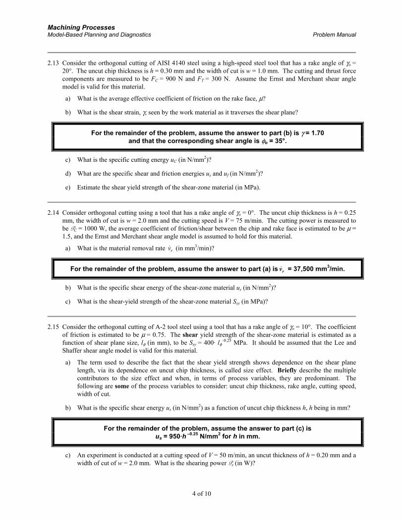
2.13 Consider the orthogonal cutting of AISI 4140 steel using a high-speed steel tool that has a rake angle of γo =
20°. The uncut chip thickness is h = 0.30 mm and the width of cut is w = 1.0 mm. The cutting and thrust force components are measured to be FC = 900 N and FT = 300 N. Assume the Ernst and Merchant shear angle model is valid for this material.
a) What is the average effective coefficient of friction on the rake face, µ?
b) What is the shear strain, γ, seen by the work material as it traverses the shear plane?
For the remainder of the problem, assume the answer to part (b) is γ = 1.70 and that the corresponding shear angle is φo = 35°.
c) What is the specific cutting energy uC (in N/mm2)?
d) What are the specific shear and friction energies us and uf (in N/mm2)?
e) Estimate the shear yield strength of the shear-zone material (in MPa).
2.14 Consider orthogonal cutting using a tool that has a rake angle of γo = 0°. The uncut chip thickness is h = 0.25
mm, the width of cut is w = 2.0 mm and the cutting speed is V = 75 m/min. The cutting power is measured to be PC = 1000 W, the average coefficient of friction/shear between the chip and rake face is estimated to be µ = 1.5, and the Ernst and Merchant shear angle model is assumed to hold for this material.
a) What is the material removal rate rv (in mm3/min)?
For the remainder of the problem, assume the answer to part (a) is rv = 37,500 mm3/min.
b) What is the specific shear energy of the shear-zone material us (in N/mm2)?
c) What is the shear-yield strength of the shear-zone material Ssy (in MPa)?
2.15 Consider the orthogonal cutting of A-2 tool steel using a tool that has a rake angle of γo = 10°. The coefficient
of friction is estimated to be µ = 0.75. The shear yield strength of the shear-zone material is estimated as a function of shear plane size, lφ (in mm), to be Ssy = 400· lφ
–0.25 MPa. It should be assumed that the Lee and Shaffer shear angle model is valid for this material.
a) The term used to describe the fact that the shear yield strength shows dependence on the shear plane length, via its dependence on uncut chip thickness, is called size effect. Briefly describe the multiple contributors to the size effect and when, in terms of process variables, they are predominant. The following are some of the process variables to consider: uncut chip thickness, rake angle, cutting speed, width of cut.
b) What is the specific shear energy us (in N/mm2) as a function of uncut chip thickness h, h being in mm?
For the remainder of the problem, assume the answer to part (c) is us = 950·h –0.25 N/mm2 for h in mm.
c) An experiment is conducted at a cutting speed of V = 50 m/min, an uncut thickness of h = 0.20 mm and a width of cut of w = 2.0 mm. What is the shearing power Ps (in W)?

Machining Processes Model-Based Planning and Diagnostics Problem Manual
5 of 10
d) From the information accumulated so far (Ssy, a, V, γo, φo and µ), can the FCD be drawn? Why/how or why not? Sketching (or attempting to sketch) the FBD may help, but is not necessary.
Chapter 3 3.1 Consider oblique cutting, using a tool that has an orthogonal rake angle of γo = 10° and an inclination angle of
λ = 30°. The uncut chip thickness is h = 0.25 mm, the width of cut is w = 2.5 mm and the cutting speed is V = 200 m/min. Assume that Stabler’s Rule is valid.
a) Sketch a 2-D view of the process, including all hidden lines, projected in the plane in which the orthogonal rake angle is measured. Label the uncut chip thickness h and orthogonal rake angle γo.
b) Sketch a 2-D view of the process, including all hidden lines, projected in the plane in which the normal rake angle is measured. Label the uncut chip thickness h and normal rake angle γn.
c) What is the normal rake angle γn (in degrees)?
For the remainder of the problem, assume the answer to part (c) is γn = 8.5°.
d) What is the effective rake angle γe (in degrees)?
e) Sketch a 2-D view of the process, including all hidden lines, projected in the plane in which the chip flow angle is measured. Label the chip velocity Vc and the chip-flow angle ηγ.
3.2 Consider oblique cutting, using a tool that has a normal rake angle of γn = 10° and an inclination angle of λ =
20°. The uncut chip thickness is h = 0.25 mm, the width of cut is w = 2.5 mm and the cutting speed is V = 200 m/min. The normal shear angle and rake face coefficient of friction (µ — not a “normal” coefficient µn) have been determined to be φn = 30° and µ = 0.50, respectively. The shear-zone shear-yield strength is estimated to be Ssy = 375 MPa.
a) Calculate the chip flow angle ηγ (in degrees) based on Armarego’s solution.
For the remainder of the problem, assume the answer to part (a) is ηγ = 17.2°.
b) What is the specific shear energy us (in N/mm2) and the in-plane shear force component Pφ (in N)?
For the remainder of the problem, assume the answer to part (b) is Pφ = 500 N.
c) What is the in-plane rake face force component Pγ (in N). Hint: One way is to calculate Pφn using ηφ and Pφ, then calculate Pγn using βn and any FCD relations, then calculate Pγ from Pγn and ηγ. In other words, use the FCD and its relations for the force components in the normal plane. See problem 0 and compare. There is another very quick way if you can find it in the text.
d) What are the specific cutting, thrust and lateral energies uC, uT and uL (in N/mm2)? Hint: Calculate FC, FT and FL from either Nφ, Pφn, and Pφs, or Nγ, Pγn, and Pγs, using the inverse of the transformations provided in the text.
Machining Processes Model-Based Planning and Diagnostics Problem Manual
6 of 10
e) What are the cutting power PC (in kW) and the material removal rate rv (in mm3/min)?
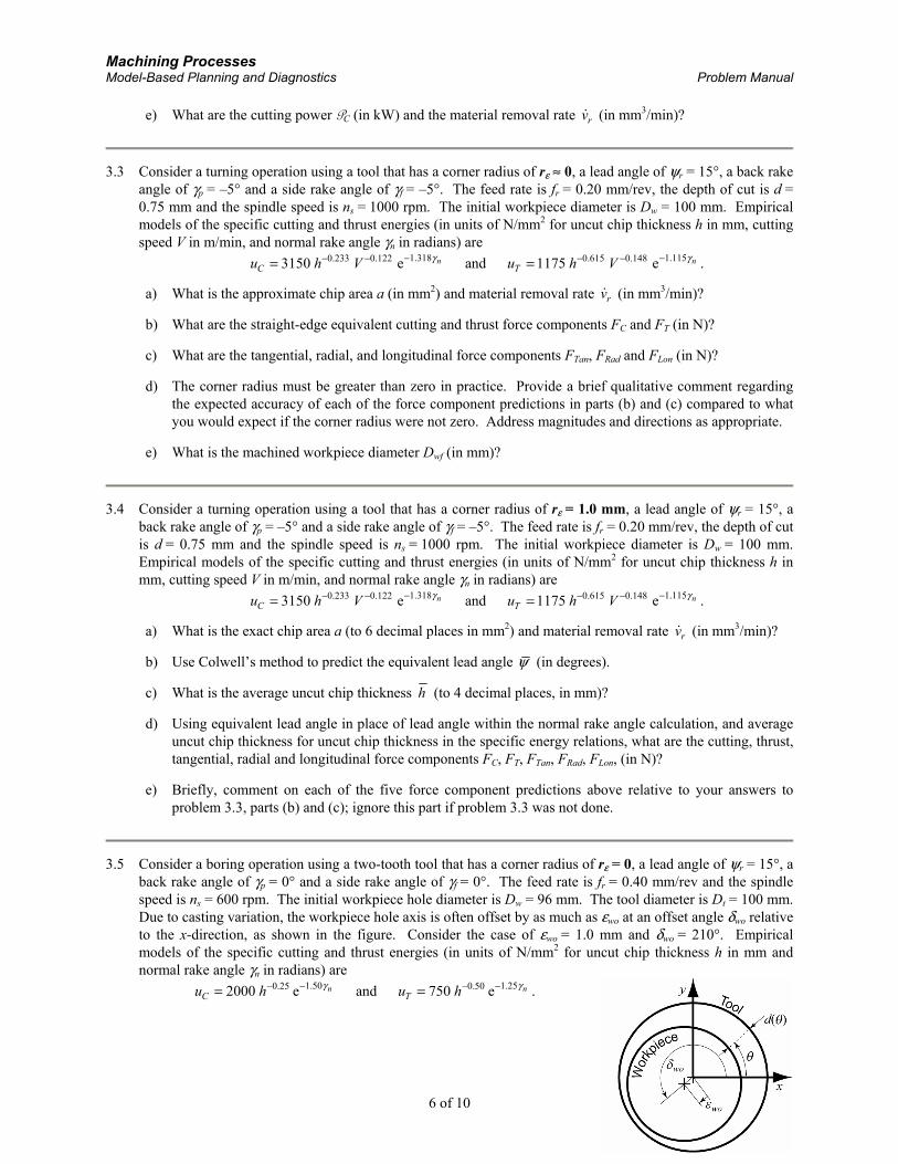
3.3 Consider a turning operation using a tool that has a corner radius of rε ≈ 0, a lead angle of ψr = 15°, a back rake
angle of γp = –5° and a side rake angle of γf = –5°. The feed rate is fr = 0.20 mm/rev, the depth of cut is d = 0.75 mm and the spindle speed is ns = 1000 rpm. The initial workpiece diameter is Dw = 100 mm. Empirical models of the specific cutting and thrust energies (in units of N/mm2 for uncut chip thickness h in mm, cutting speed V in m/min, and normal rake angle γn in radians) are
1.318 1.1150.233 0.122 0.615 0.1483150 e and 1175 en nC Tu h V u h Vγ γ− −− − − −= = .
a) What is the approximate chip area a (in mm2) and material removal rate rv (in mm3/min)?
b) What are the straight-edge equivalent cutting and thrust force components FC and FT (in N)?
c) What are the tangential, radial, and longitudinal force components FTan, FRad and FLon (in N)?
d) The corner radius must be greater than zero in practice. Provide a brief qualitative comment regarding the expected accuracy of each of the force component predictions in parts (b) and (c) compared to what you would expect if the corner radius were not zero. Address magnitudes and directions as appropriate.
e) What is the machined workpiece diameter Dwf (in mm)?
3.4 Consider a turning operation using a tool that has a corner radius of rε = 1.0 mm, a lead angle of ψr = 15°, a
back rake angle of γp = –5° and a side rake angle of γf = –5°. The feed rate is fr = 0.20 mm/rev, the depth of cut is d = 0.75 mm and the spindle speed is ns = 1000 rpm. The initial workpiece diameter is Dw = 100 mm. Empirical models of the specific cutting and thrust energies (in units of N/mm2 for uncut chip thickness h in mm, cutting speed V in m/min, and normal rake angle γn in radians) are
1.318 1.1150.233 0.122 0.615 0.1483150 e and 1175 en nC Tu h V u h Vγ γ− −− − − −= = .
a) What is the exact chip area a (to 6 decimal places in mm2) and material removal rate rv (in mm3/min)?
b) Use Colwell’s method to predict the equivalent lead angle ψ (in degrees).
c) What is the average uncut chip thickness h (to 4 decimal places, in mm)?
d) Using equivalent lead angle in place of lead angle within the normal rake angle calculation, and average uncut chip thickness for uncut chip thickness in the specific energy relations, what are the cutting, thrust, tangential, radial and longitudinal force components FC, FT, FTan, FRad, FLon, (in N)?
e) Briefly, comment on each of the five force component predictions above relative to your answers to problem 3.3, parts (b) and (c); ignore this part if problem 3.3 was not done.
3.5 Consider a boring operation using a two-tooth tool that has a corner radius of rε = 0, a lead angle of ψr = 15°, a
back rake angle of γp = 0° and a side rake angle of γf = 0°. The feed rate is fr = 0.40 mm/rev and the spindle speed is ns = 600 rpm. The initial workpiece hole diameter is Dw = 96 mm. The tool diameter is Dt = 100 mm. Due to casting variation, the workpiece hole axis is often offset by as much as εwo at an offset angle δwo relative to the x-direction, as shown in the figure. Consider the case of εwo = 1.0 mm and δwo = 210°. Empirical models of the specific cutting and thrust energies (in units of N/mm2 for uncut chip thickness h in mm and normal rake angle γn in radians) are
1.50 1.250.25 0.502000 e and 750 en nC Tu h u hγ γ− −− −= = .
Machining Processes Model-Based Planning and Diagnostics Problem Manual
7 of 10
a) What are the maximum and minimum depths of cut d(θmaxd) and d(θmind) (in mm) experienced by a tooth, and at what tool angles, θmaxd and θmind (in degrees) respectively, do these values occur?
b) What are the minimum and maximum of the cutting force component FC(θminC) and FC(θmaxC) (in N) experienced by a tooth, and at what tool angles, θminC and θmaxC (in degrees) respectively, do these values occur?
c) Based on the geometry of two offset circles, show that the exact solution for the depth of cut as a function of tooth angle θi is
( )1/ 22 2( ) cos( ) sin ( )i t wo wo i w wo wo id R Rθ ε δ θ ε δ θ = − − + − −
.
Then, derive a more simple approximation by neglecting certain “small” terms here.
d) Graph the x- and y-force components Fx and Fy (in N) as functions of spindle angle θs where, by convention, the angle of tooth one is θ1 = θs.
e) Briefly describe what you think, without calculation, would happen to the maximum and minimum x- and y-force components if the corner radius was considered to be its actual value, rε > 0?
f) What is the machined workpiece diameter Dwf (in mm)?
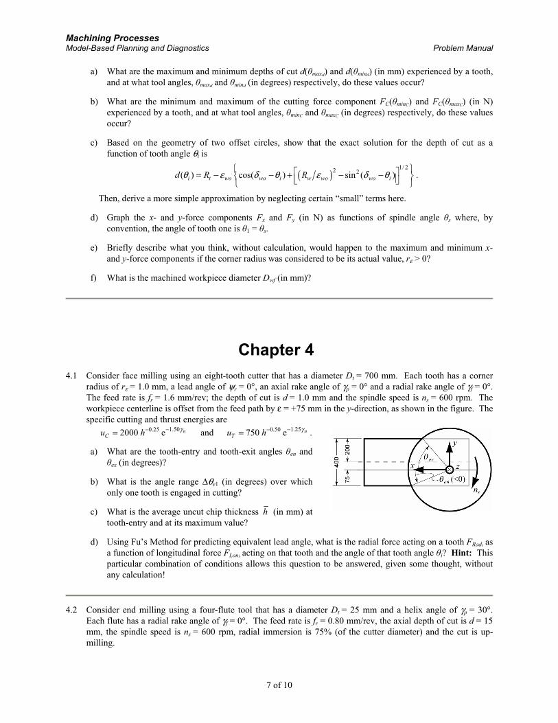
Chapter 4 4.1 Consider face milling using an eight-tooth cutter that has a diameter Dt = 700 mm. Each tooth has a corner
radius of rε = 1.0 mm, a lead angle of ψr = 0°, an axial rake angle of γp = 0° and a radial rake angle of γf = 0°. The feed rate is fr = 1.6 mm/rev; the depth of cut is d = 1.0 mm and the spindle speed is ns = 600 rpm. The workpiece centerline is offset from the feed path by ε = +75 mm in the y-direction, as shown in the figure. The specific cutting and thrust energies are
1.50 1.250.25 0.502000 e and 750 en nC Tu h u hγ γ− −− −= = .
a) What are the tooth-entry and tooth-exit angles θen and θex (in degrees)?
b) What is the angle range ∆θe1 (in degrees) over which only one tooth is engaged in cutting?
c) What is the average uncut chip thickness h (in mm) at tooth-entry and at its maximum value?
d) Using Fu’s Method for predicting equivalent lead angle, what is the radial force acting on a tooth FRadi as a function of longitudinal force FLoni acting on that tooth and the angle of that tooth angle θi? Hint: This particular combination of conditions allows this question to be answered, given some thought, without any calculation!
4.2 Consider end milling using a four-flute tool that has a diameter Dt = 25 mm and a helix angle of γp = 30°.
Each flute has a radial rake angle of γf = 0°. The feed rate is fr = 0.80 mm/rev, the axial depth of cut is d = 15 mm, the spindle speed is ns = 600 rpm, radial immersion is 75% (of the cutter diameter) and the cut is up-milling.

Machining Processes Model-Based Planning and Diagnostics Problem Manual
8 of 10
a) What are the tooth-entry and tooth-exit angles θen and θex (in degrees)?
b) Draw to scale the flute-engagement diagram for the case when the angle of tooth number one, when measured at the end of the cutter (θ1|z=0), is zero.
c) What is the maximum engaged wrap angle (in degrees) that a single flute can experience?
d) Assume size effect is ignored so that the specific cutting and thrust energies take on constant values, for the given speed and rake angles, of uC = 1500 N/mm2 and uT = 1000 N/mm2. If the immersion is changed to 100% (slotting), what are the peak x- and y- force components acting on the cutter, Fx and Fy, (in N)? Hint: Think about this in terms of face milling with Dt/Ww = 1.
e) Again ignoring size effect, what would be the dominant frequency (in Hz) of the total x- and y-force signatures for each case, i.e., for 75% immersion and 100% immersion?
4.3 Consider drilling a 10-mm diameter hole using a standard conical-point twist drill that has a web thickness
2bw = 1 mm and chisel edge angle of ϕ = 135°.
a) By numerically integrating γn(r) from the web to the outer diameter (where r = Rt), then dividing by the integration range (Rt – r(at web)), calculate an average normal rake angle nγ (in degrees).
b) At what radial position r (in mm) does the average normal rake angle occur?
c) What is the inclination angle λ (in degrees) at the average normal rake angle position r ?
Chapter 5 5.1 Consider the data in the table that were obtained from a turned surface (z in mm and r(z) in µm). Note that the
sample increment is 0.021 mm.
z (mm)
r(z) (µm)
z (mm)
r(z) (µm)
z (mm)
r(z) (µm)
z (mm)
r(z) (µm)
z (mm)
r(z) (µm)
z (mm)
r(z) (µm)
0.000 38.1 0.104 44.7 0.208 40.9 0.313 42.3 0.417 40.2 0.521 36.70.021 39.2 0.125 53.9 0.229 36.1 0.333 41.8 0.438 36.5 0.542 36.50.042 38.6 0.146 46.1 0.250 35.8 0.354 43.0 0.458 37.8 0.563 39.20.063 42.2 0.167 39.4 0.271 35.8 0.375 53.3 0.479 35.2 0.583 43.10.083 45.5 0.188 38.0 0.292 39.9 0.396 48.1 0.500 34.6 0.604 49.0
a) Graph the measured surface profile and estimate the feed rate fr (in mm/rev) and the corner radius rε (in mm). Assume only the corner radius forms the surface (i.e., the lead and trail cutting edges do not contact the final surface).
b) Calculate the peak-to-valley (rt), center-line (rcl), roughness-average (ra), and RMS roughness (rq) values (in µm) using the discrete data given. First use a 0.604 mm cutoff, then use only the data from z = 0.0 to 0.500 mm. Comment on the differences in your results, if any.
c) Estimate the peak-to-valley (Rt), center-line (rcl), roughness-average (ra), and RMS roughness (rq) values (in µm) based on the zero corner radius analytical model, using the feed rate determined in part (a) and assuming the lead angle is ψr = 15° and the end cutting edge angle κr’ = 15°. What are the percent errors in these calculated values relative to those found in part (b)?

Machining Processes Model-Based Planning and Diagnostics Problem Manual
9 of 10
d) Estimate the roughness-average value ra (in µm) using Boothroyd’s empirical model using the corner radius value determined in part (a). What is the percent error in this calculated value relative to that found in part (b)?
5.2 For arbitrary tooth feed f and corner radius rε, assuming the machined surface is generated by the corner arc
only (i.e., no portion of the surface is generated by the lead or end cutting edges), use analytical integration to derive closed-form expressions for the following values.
a) The roughness height r(z), relative to the valley bottom, in terms of position z (z = 0 at the corner radius center), tooth feed f and corner radius rε.
b) The centerline value rcl in terms of corner radius rε and tooth feed f.
c) The roughness-average value in terms of the centerline value rcl, corner radius rε and tooth feed f.
Chapter 6
Chapter 7 7.1 Consider the flank wear versus time data in the table.
t (min)
W(t) (mm)
t (min)
W(t) (mm)
t (min)
W(t) (mm)
t (min)
W(t) (mm)
t (min)
W(t) (mm)
t (min)
W(t) (mm)
0.0 0.016 1.5 0.370 4.0 0.782 7.0 1.145 10.0 2.196 12.0 3.0500.5 0.145 2.0 0.458 5.0 0.854 8.0 1.357 11.0 2.505 12.5 3.0811.0 0.262 3.0 0.643 6.0 1.098 9.0 1.703 11.5 2.687 13.0 3.373
a) Develop an estimating model for wear level as a function of time.
b) Estimate, either graphically or mathematically, the tool life tl for a critical wear level of Wl = 0.5 mm.
7.2 Estimate Taylor’s exponent n and constant C (in m/min) for the HSS tool-life data in the table.
V (m/min)
tl (min)
V (m/min)
tl (min)
V (m/min)
tl (min)
V (m/min)
tl (min)
V (m/min)
tl (min)
V (m/min)
tl (min)
25 25.708 100 4.009 175 1.503 250 1.054 325 0.672 400 0.54150 10.012 125 2.949 200 1.442 275 0.804 350 0.643 425 0.48375 5.183 150 2.075 225 1.186 300 0.796 375 0.609 450 0.438
7.3 Consider the continuous turning of a bar that has a diameter of Dw = 50 mm and length of Lw = 200 mm. The
feed rate is fr =0.25 mm/rev. Taylor’s tool-life model parameters are C = 150 m/min and n = 0.1. The time to change one tooth is tc’ = 0.75 min/tooth, the material handling time is th = 0.5 min/part, the cost of a new cutting tooth is ct’ =2 $/tooth and the overhead cost is co = 1.5 $/min.
a) What is the minimum unit time tumin (in min/part)?

Machining Processes Model-Based Planning and Diagnostics Problem Manual
10 of 10
b) At what spindle speed ns (in rev/min) is the minimum unit time achieved?
c) What is the unit cost cu (in $/part) associated with achieving minimum unit time?
7.4 Consider the continuous turning of a bar that has a diameter of Dw = 50 mm and length of Lw = 200 mm. The
feed rate is fr =0.25 mm/rev. Taylor’s tool-life model parameters are C = 150 m/min and n = 0.1. The time to change one tooth is tc’ = 0.75 min/tooth, the material handling time is th = 0.5 min/part, the cost of a new cutting tooth is ct’ =2 $/tooth and the overhead cost is co = 1.5 $/min.
a) What is the minimum unit cost cumin (in $/part)?
b) At what spindle speed ns (in rev/min) is the minimum unit cost achieved?
c) What is the unit time tu (in min/part) associated with achieving minimum unit cost?
7.5 Consider the continuous turning of a bar that has a diameter of Dw = 50 mm and length of Lw = 200 mm. The
feed rate is fr =0.25 mm/rev. Taylor’s tool-life model parameters are C = 150 m/min and n = 0.1. The time to change one tooth is tc’ = 0.75 min/tooth, the material handling time is th = 0.5 min/part, the cost of a new cutting tooth is ct’ =2 $/tooth and the overhead cost is co = 1.5 $/min.
a) At what cutting speed V (in m/min) is maximum unit profit achieved?
b) At what cutting speed V (in m/min) is maximum unit profit rate achieved?
c) What is the unit cost cu (in $/part) associated with achieving minimum unit profit?
7.6 Consider face milling using an eight-tooth cutter that has a diameter Dt = 300 mm and holds square inserts
each having four usable edges. The workpiece has width of Ww = 200 mm, length of Lw = 400 mm and no surface voids. The feed rate is fr = 2.0 mm/rev and the depth of cut is d = 1.5 mm. Economic information includes the following:
Tool life model: C = 250, n = 0.25. Inserts cost $8 each. It takes 4 minutes to change each tooth. It takes 5 minutes to load the workpiece and another 5 minutes to unload the workpiece. The overhead rate is 120 $/hour.
a) What spindle speed ns (in rev/min) results in minimum unit time?
b) What spindle speed ns (in rev/min) results in minimum unit cost?
c) What spindle speed ns (in rev/min) results in maximum unit profit?
d) If the unit profit, when profit rate is maximized, is to be 10% of the unit revenue, what should the unit revenue ru be (in $/part)? Hint: The solution is likely to require iteration, besides the iteration related to determining V$.
e) What would be the machining time tm and engagement time te (in min/part), as functions of cutting speed V, if there was a 100-mm diameter hole in the surface, running perpendicular to the machined surface, and all the way through the workpiece?