machining 2 stsengs855 mem09002b-interpret technical drawing mem07005a-general machining ...
TRANSCRIPT

Machining 2STSENGS855
MEM09002B-interpret technical drawingMEM07005A-general machining
http://machineshop.coe.drexel.edu/machineshop/equipment/milling-machines.jpg
Chapter 1
Determine job requirements:

IntroductionIn order for parts of a product to fit together accurately, engineers need to be able to understand engineering drawings so that they can make the parts accurately.
In some cases, the parts to a product are not always manufactured in the same country. Therefore it is important that Engineering drawings follow the same format so that they can be understood all over the world.
http://kumasicenter.files.wordpress.com/2012/10/engineering-drawings.jpg
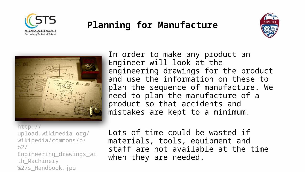
Planning for Manufacture
In order to make any product an Engineer will look at the engineering drawings for the product and use the information on these to plan the sequence of manufacture. We need to plan the manufacture of a product so that accidents and mistakes are kept to a minimum.
Lots of time could be wasted if materials, tools, equipment and staff are not available at the time when they are needed.
http://upload.wikimedia.org/wikipedia/commons/b/b2/Engineering_drawings_with_Machinery%27s_Handbook.jpg
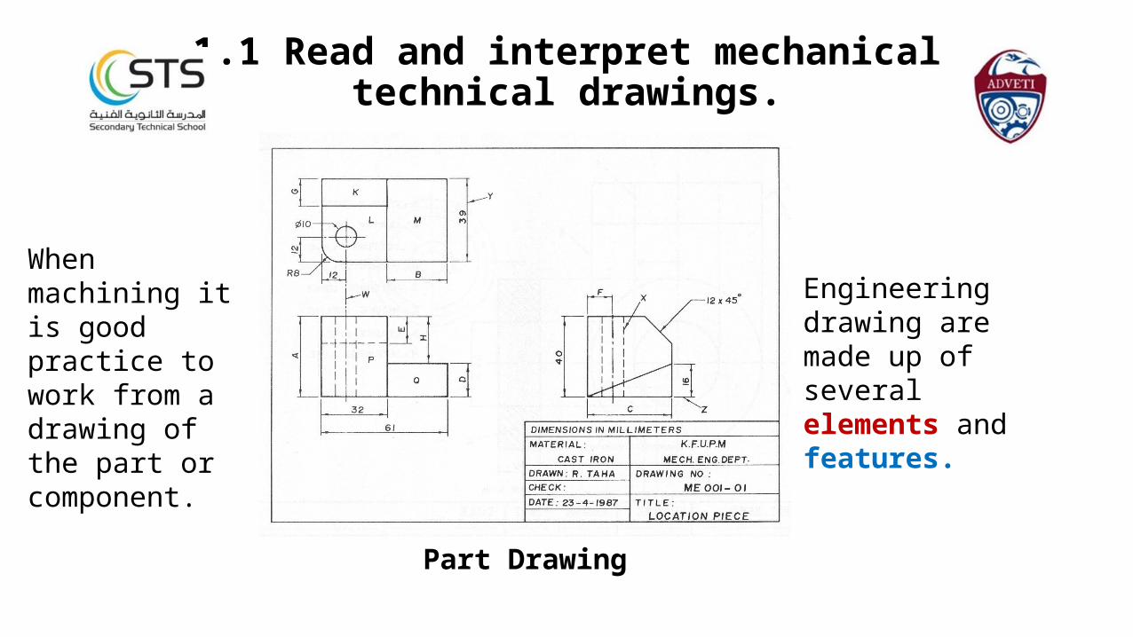
1.1 Read and interpret mechanicaltechnical drawings.
When machining it is good practice to work from a drawing of the part or component.
Part Drawing
Engineering drawing are made up of several elements and features.
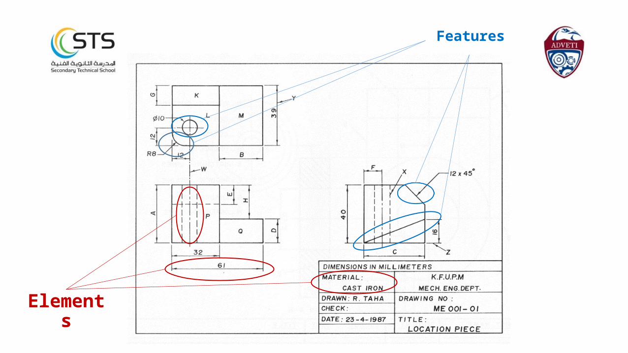
Elements
Features
Elements of a part drawingThese are defined as ‘information aspects’ on the drawing.Material: in this case the material to be used is cast iron, however on some drawings you might come across the following:
BMS – bright mild steel
Dimensions: these values inform the engineer of the overall size of the finished part such as height, width and length.
Centre Line: this tells the engineer where to start a particular machined feature.
Features of a part drawingThese are identified by the shape and appearance of the designed part. Edges: the drawing tells us that the location piece needs to have two different machined slope features.
Hole: the drawing tells us that we need a 10 mm drill bit and that we need to drill a hole depth of 40 mm.
Radius: The machine operator can plan ahead by making sure he has all the tools ready for cutting this type of feature.
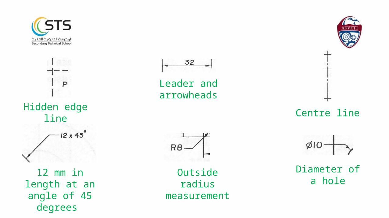
Hidden edge line
Leader and arrowheads
Centre line
12 mm in length at an angle of 45
degrees
Outside radius measurement
Diameter of a hole
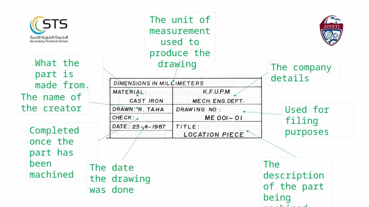
What the part is made from.
The name of the creator
The date the drawing was done
Completed once the part has been machined
The company details
Used for filing purposes
The description of the part being machined
The unit of measurement
used to produce the drawing
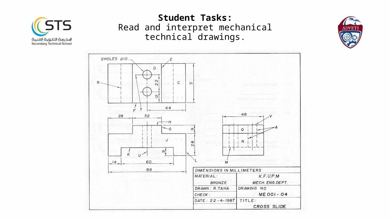
Student Tasks:Read and interpret mechanical
technical drawings.
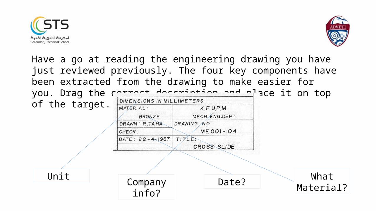
Have a go at reading the engineering drawing you have just reviewed previously. The four key components have been extracted from the drawing to make easier for you. Drag the correct description and place it on top of the target.
What Material?Date?Company
info?
Unit
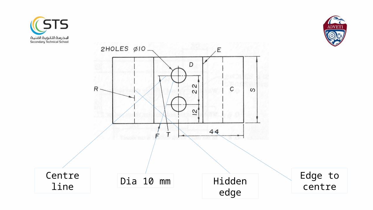
Edge to centreHidden edgeDia 10 mmCentre line
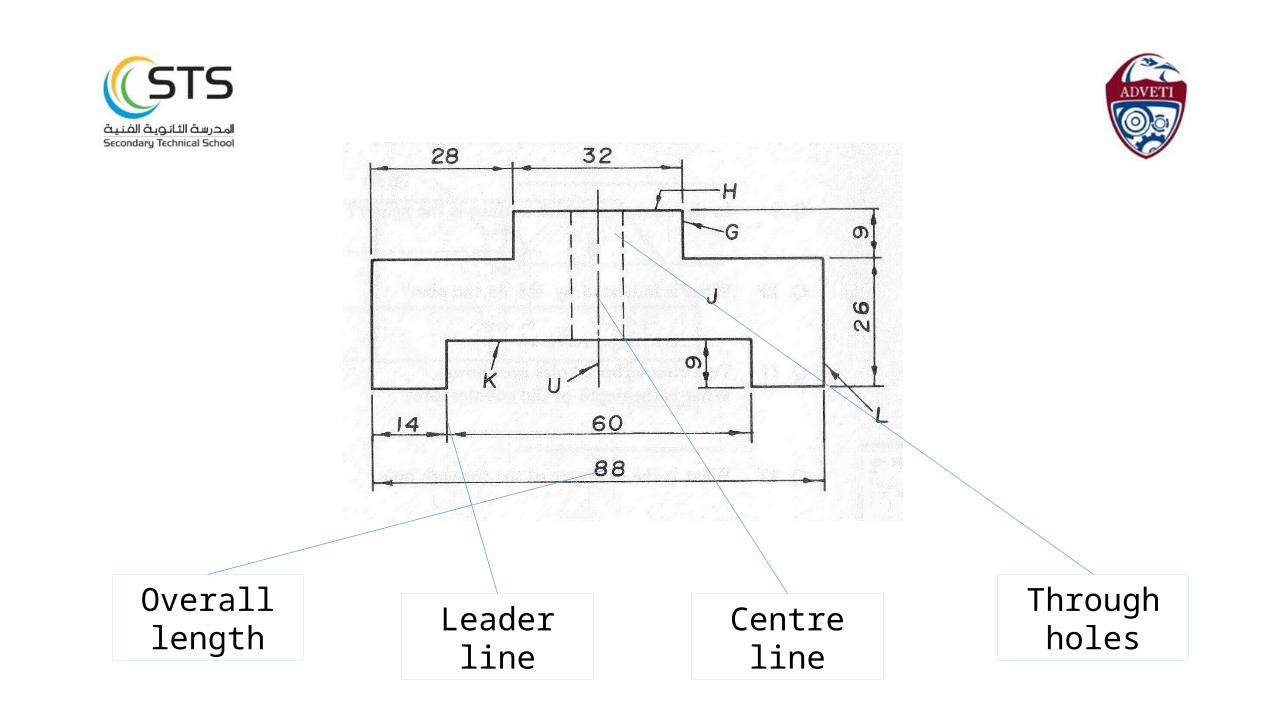
Through holesCentre lineLeader lineOverall
length
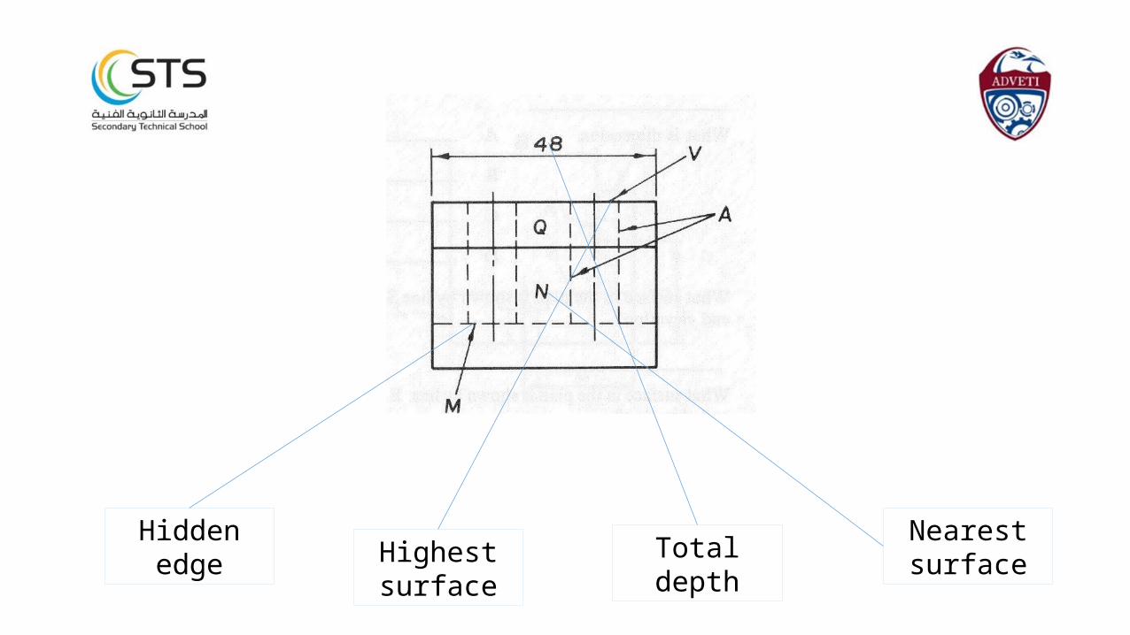
Nearest surfaceTotal depthHighest
surface
Hidden edge

1.2 Determine and transferdimensions from given technical drawings
using datum points.
Machine operators are expected to produce engineering parts to the accuracy of the given drawing. Therefore it is important that the information regarding size and shape is clear and easy to interpret.
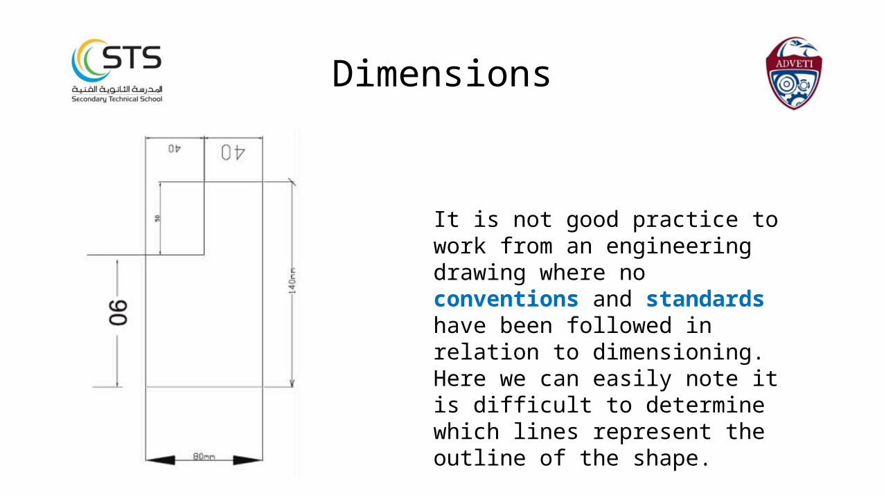
It is not good practice to work from an engineering drawing where no conventions and standards have been followed in relation to dimensioning. Here we can easily note it is difficult to determine which lines represent the outline of the shape.
Dimensions
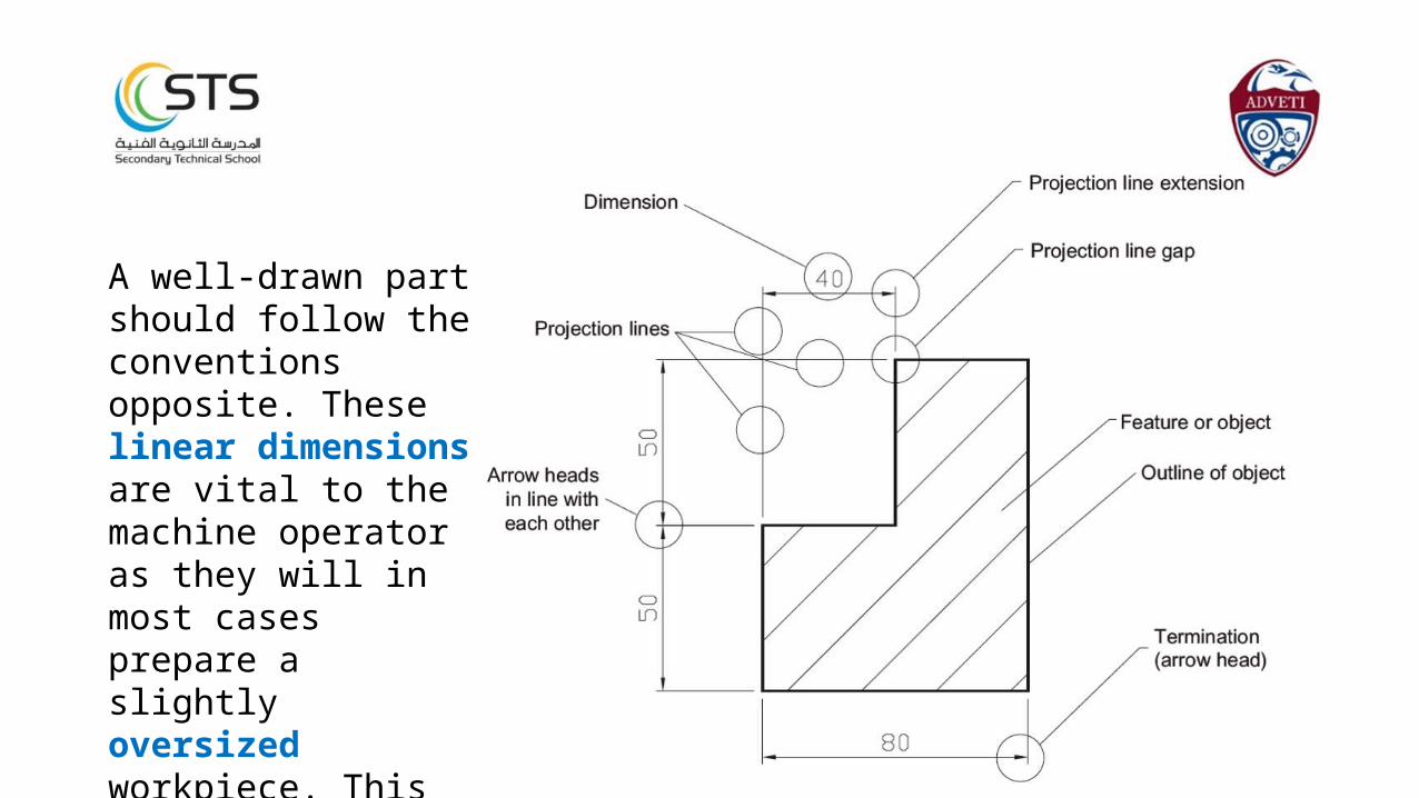
A well-drawn part should follow the conventions opposite. These linear dimensions are vital to the machine operator as they will in most cases prepare a slightly oversized workpiece. This will reduce the amount of waste material after machining the part.
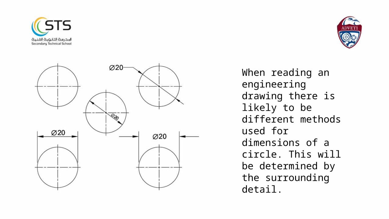
When reading an engineering drawing there is likely to be different methods used for dimensions of a circle. This will be determined by the surrounding detail.
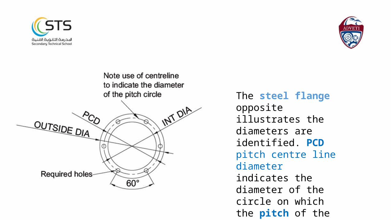
The steel flange opposite illustrates the diameters are identified. PCD pitch centre line diameter indicates the diameter of the circle on which the pitch of the holes is centred. The pitch of the circles is 60°.
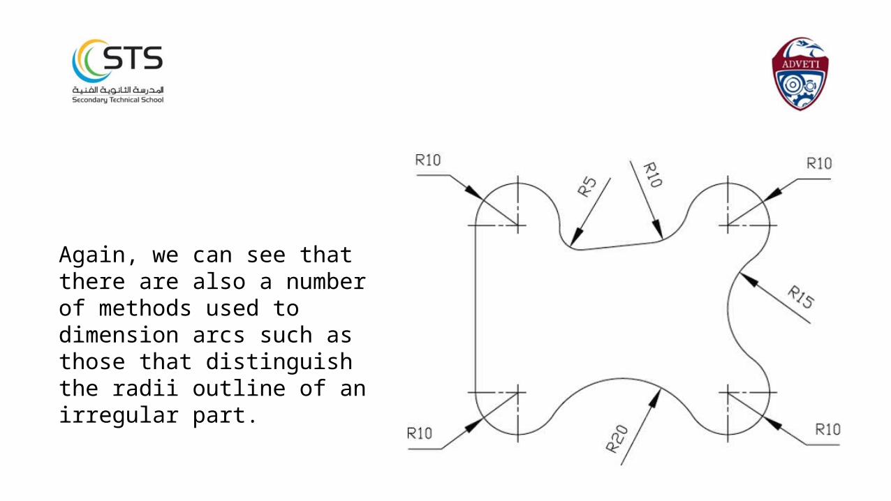
Again, we can see that there are also a number of methods used to dimension arcs such as those that distinguish the radii outline of an irregular part.

Tolerance is the allowable variation in weight or measurement of an object. It is important for a machine operator to work to a tolerance because it is not always possible to produce parts exactly to the specified measurements.
Tolerances
Piston in it’s cylinder of an engine
The piston rings have to be machined to a specific tolerance to prevent the engine from losing power. If the diameter is greater then the piston will be subject to high levels of friction and visa versa.
Piston
Cylinder
http://s1.hubimg.com/u/623790_f520.jpg
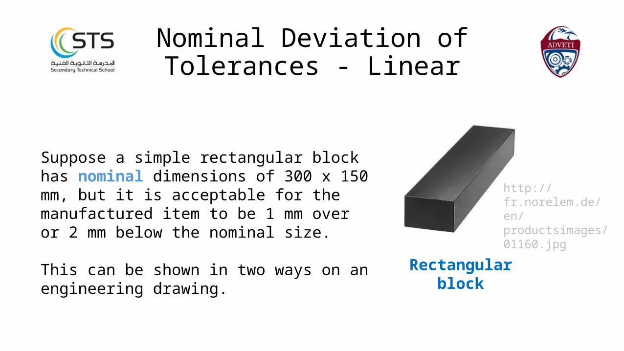
Suppose a simple rectangular block has nominal dimensions of 300 x 150 mm, but it is acceptable for the manufactured item to be 1 mm over or 2 mm below the nominal size.
This can be shown in two ways on an engineering drawing. Rectangular block
http://fr.norelem.de/en/productsimages/01160.jpg
Nominal Deviation ofTolerances - Linear
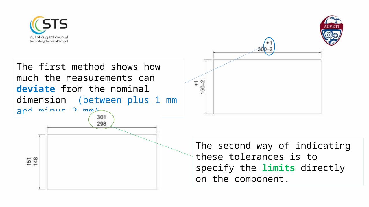
The first method shows how much the measurements can deviate from the nominal dimension (between plus 1 mm and minus 2 mm).
The second way of indicating these tolerances is to specify the limits directly on the component.
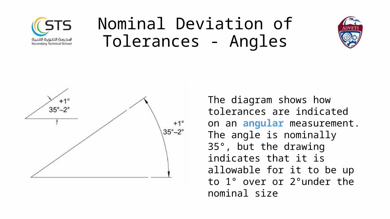
The diagram shows how tolerances are indicated on an angular measurement. The angle is nominally 35°, but the drawing indicates that it is allowable for it to be up to 1° over or 2°under the nominal size
Nominal Deviation ofTolerances - Angles
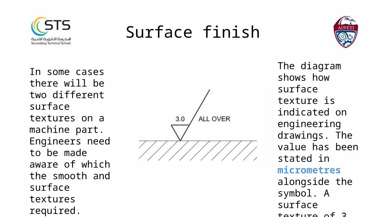
In some cases there will be two different surface textures on a machine part. Engineers need to be made aware of which the smooth and surface textures required. These need to be measurable and indicated on the drawing.
Surface finish
The diagram shows how surface texture is indicated on engineering drawings. The value has been stated in micrometres alongside the symbol. A surface texture of 3 micrometres is required all over the surfaces of the part.
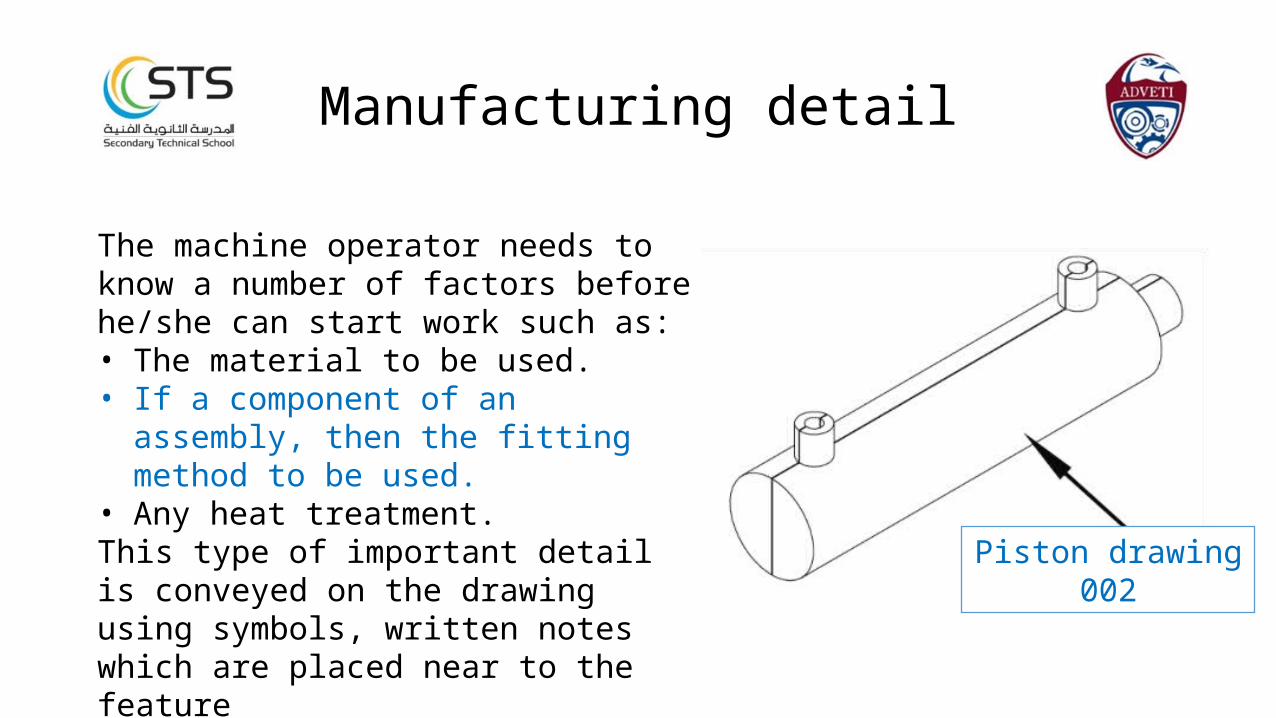
The machine operator needs to know a number of factors before he/she can start work such as:• The material to be used.• If a component of an assembly, then the
fitting method to be used.• Any heat treatment.This type of important detail is conveyed on the drawing using symbols, written notes which are placed near to the feature
Manufacturing detail
Piston drawing 002
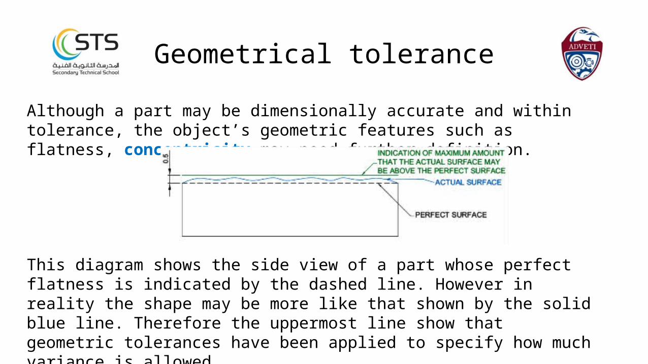
Although a part may be dimensionally accurate and within tolerance, the object’s geometric features such as flatness, concentricity may need further definition.
Geometrical tolerance
This diagram shows the side view of a part whose perfect flatness is indicated by the dashed line. However in reality the shape may be more like that shown by the solid blue line. Therefore the uppermost line show that geometric tolerances have been applied to specify how much variance is allowed.
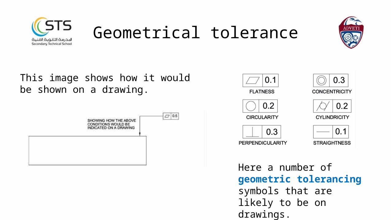
This image shows how it would be shown on a drawing.
Geometrical tolerance
Here a number of geometric tolerancing symbols that are likely to be on drawings.
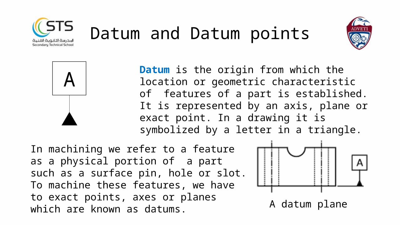
Datum is the origin from which the location or geometric characteristic of features of a part is established. It is represented by an axis, plane or exact point. In a drawing it is symbolized by a letter in a triangle.
Datum and Datum points
In machining we refer to a feature as a physical portion of a part such as a surface pin, hole or slot. To machine these features, we have to exact points, axes or planes which are known as datums.
A datum plane
A
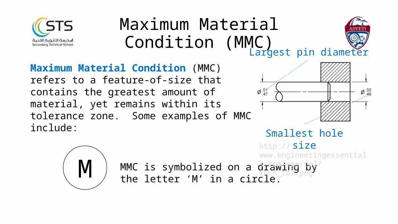
Maximum Material Condition (MMC) refers to a feature-of-size that contains the greatest amount of material, yet remains within its tolerance zone. Some examples of MMC include:
Maximum MaterialCondition (MMC)
MMC is symbolized on a drawing by the letter ‘M’ in a circle.
Smallest hole size
M
Largest pin diameter
http://www.engineeringessentials.com/ege/tol/inch_tol.png
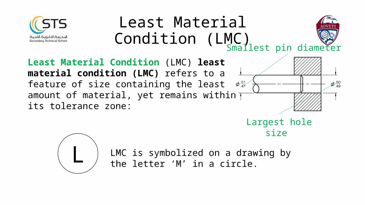
Least Material Condition (LMC) least material condition (LMC) refers to a feature of size containing the least amount of material, yet remains within its tolerance zone:
Least MaterialCondition (LMC)
LMC is symbolized on a drawing by the letter ‘M’ in a circle.
Largest hole size
L
Smallest pin diameter
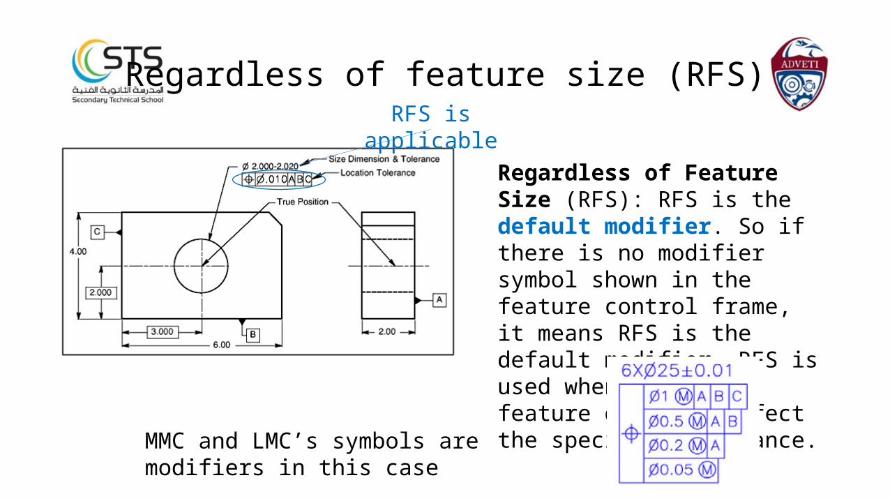
Regardless of Feature Size (RFS): RFS is the default modifier. So if there is no modifier symbol shown in the feature control frame, it means RFS is the default modifier. RFS is used when the size feature does not affect the specified tolerance.
Regardless of feature size (RFS)RFS is applicable
MMC and LMC’s symbols are modifiers in this case

On an engineering drawing you may find one of these three symbols which are all used to identify a datum.
On some cases there might be a different letter used however letter I, O and Q are not used.
Application
A
A
A
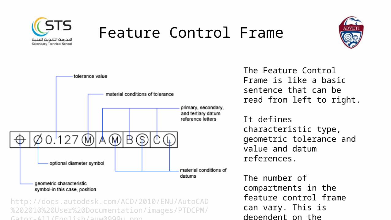
The Feature Control Frame is like a basic sentence that can be read from left to right.
It defines characteristic type, geometric tolerance and value and datum references.
The number of compartments in the feature control frame can vary. This is dependent on the characteristic type used, whether single or related and what the functional requirements are.
Feature Control Frame
http://docs.autodesk.com/ACD/2010/ENU/AutoCAD%202010%20User%20Documentation/images/PTDCPM/Gator-All/English/auw0999u.png
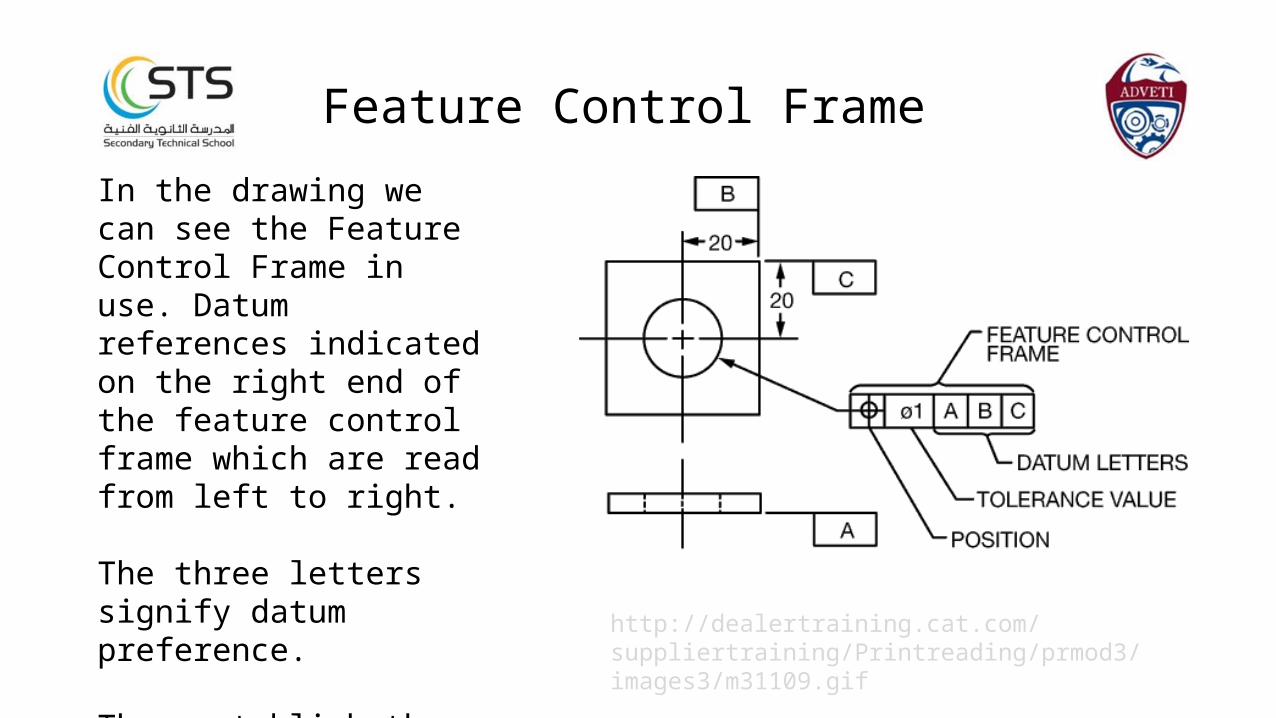
In the drawing we can see the Feature Control Frame in use. Datum references indicated on the right end of the feature control frame which are read from left to right.
The three letters signify datum preference.
They establish the three mutually perpendicular planes.
http://dealertraining.cat.com/suppliertraining/Printreading/prmod3/images3/m31109.gif
Feature Control Frame
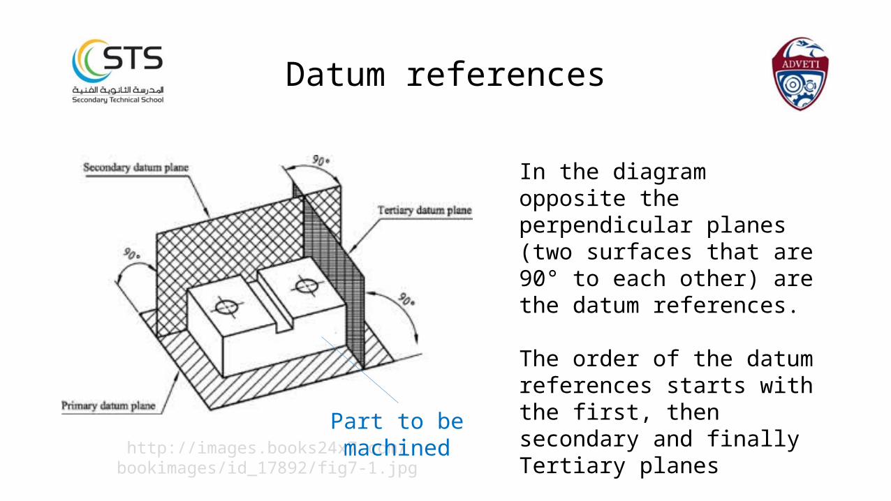
In the diagram opposite the perpendicular planes (two surfaces that are 90° to each other) are the datum references.
The order of the datum references starts with the first, then secondary and finally Tertiary planes
Datum references
http://images.books24x7.com/bookimages/id_17892/fig7-1.jpg
Part to be machined
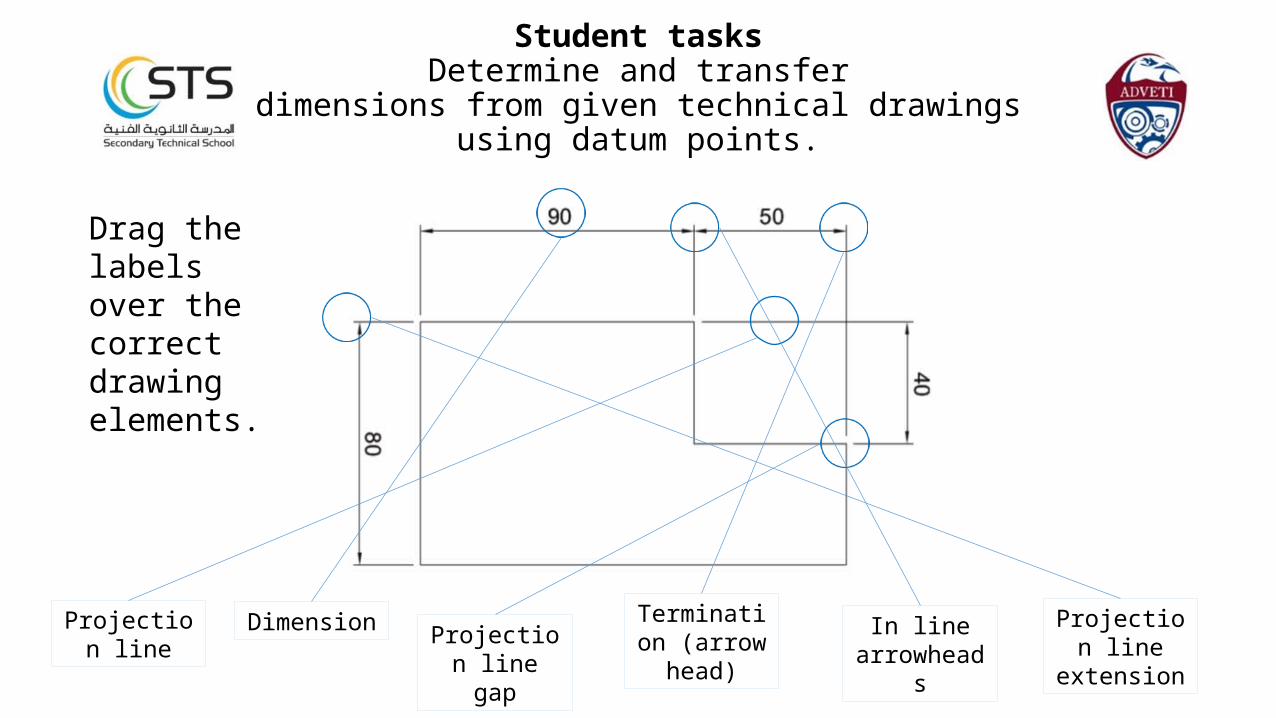
Drag the labels over the correct drawing elements.
Student tasksDetermine and transfer
dimensions from given technical drawingsusing datum points.
Projection line
Dimension Projection line gap
Termination (arrow head)
In line arrowheads
Projection line extension

Complete the different methods of dimensioning the diameter of these circles.
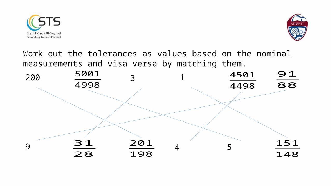
Work out the tolerances as values based on the nominal measurements and visa versa by matching them.
200
5
3 1
49 201198
45014498
3128
9188
50014998
151148
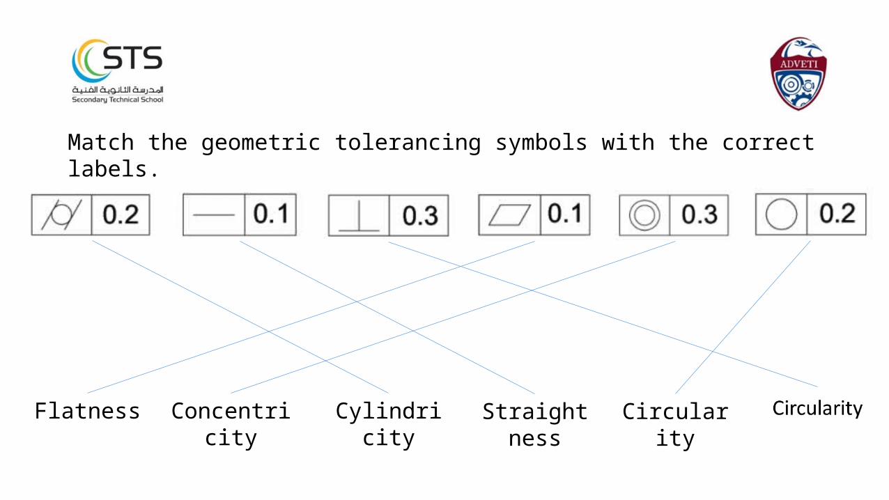
Match the geometric tolerancing symbols with the correct labels.
CylindricityFlatness Concentricity Straightness Circularity
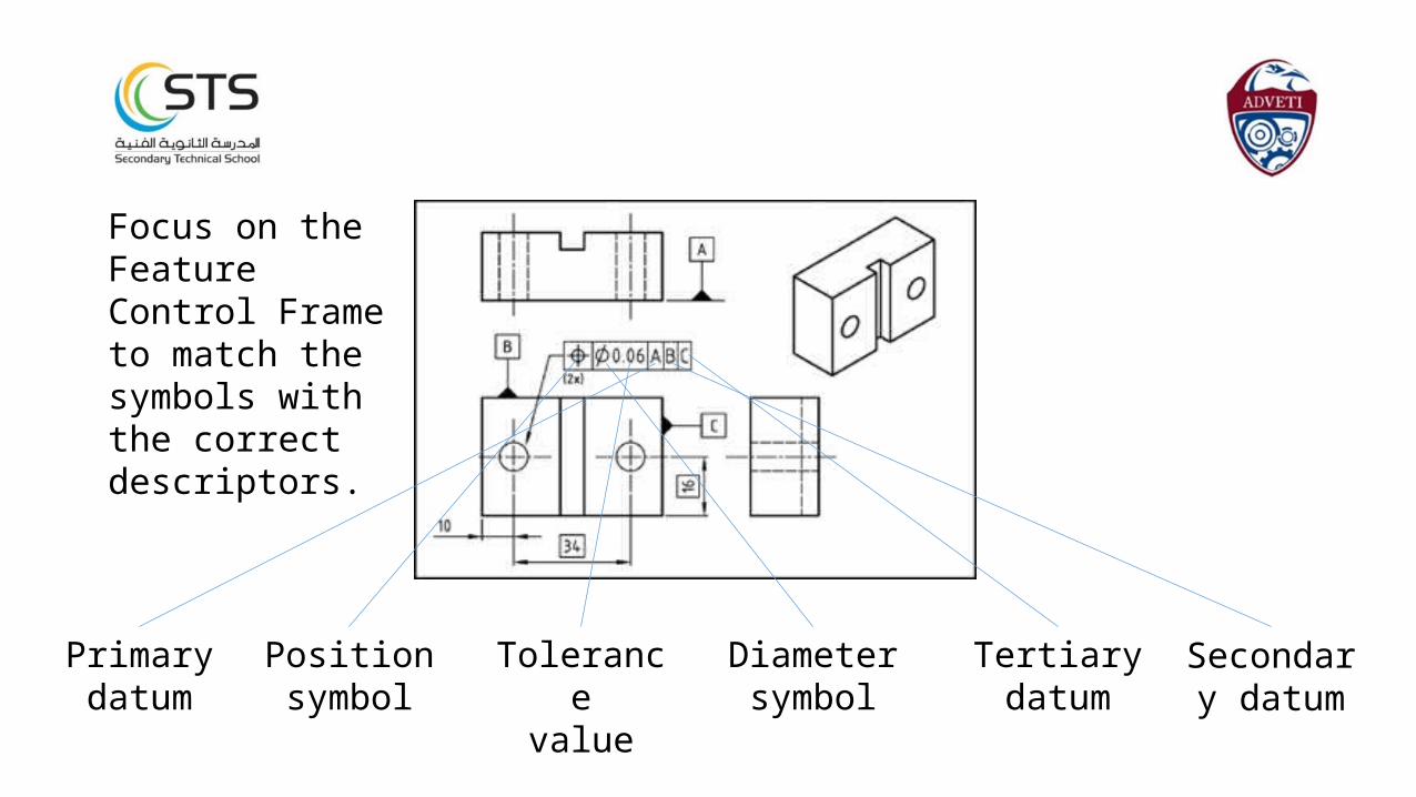
Focus on the Feature Control Frame to match the symbols with the correct descriptors.
Primary datum
Positionsymbol
Tolerancevalue
Diametersymbol
Tertiary datum
Secondary datum

Chapter 2
Determine sequence of machining operations
Introduction
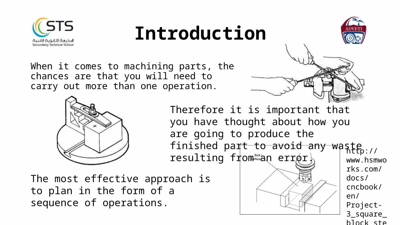
When it comes to machining parts, the chances are that you will need to carry out more than one operation.
http://www.hsmworks.com/docs/cncbook/en/Project-3_square_block_step_5-back.png
The most effective approach is to plan in the form of a sequence of operations.
Therefore it is important that you have thought about how you are going to produce the finished part to avoid any waste resulting from an error.

Planning resourcesBefore a sequence of operation can be planned, the machine operator will probably need to refer to a number of documents.To machine affectively, we need to have:
A drawing – tells us what the component or part needs to look like.
http://www.lucastechnical.com/wp-content/uploads/LTS-Engineering-Drawing-Example.png
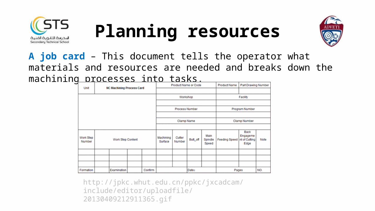
Planning resourcesA job card – This document tells the operator what materials and resources are needed and breaks down the machining processes into tasks.
http://jpkc.whut.edu.cn/ppkc/jxcadcam/include/editor/uploadfile/20130409212911365.gif
Planning resources
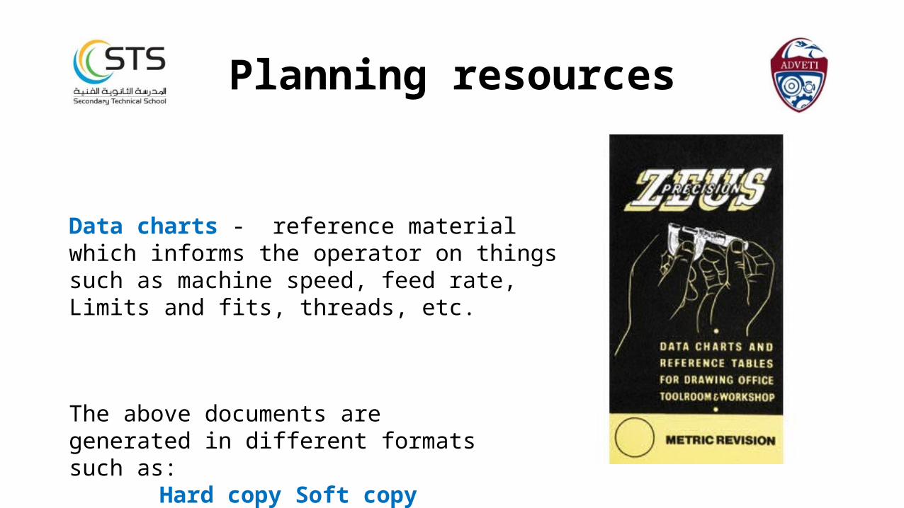
Data charts - reference material which informs the operator on things such as machine speed, feed rate, Limits and fits, threads, etc.
The above documents are generated in different formats such as:
Hard copy Soft copy
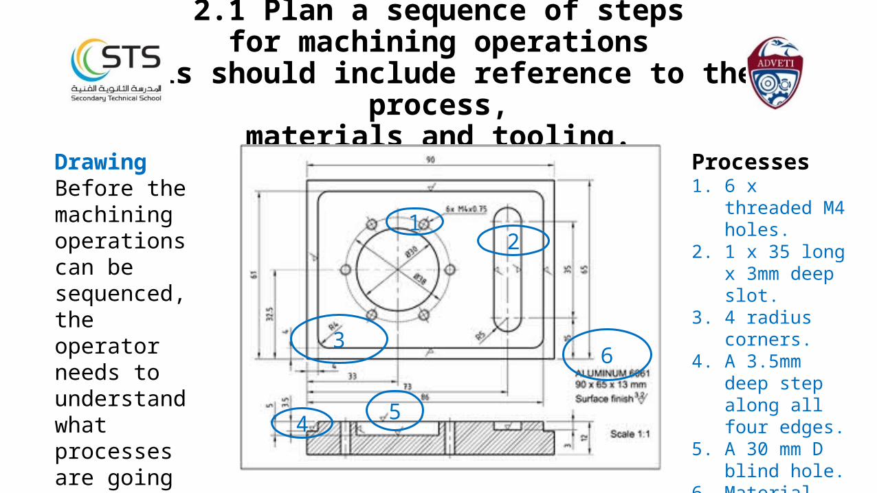
2.1 Plan a sequence of stepsfor machining operations
This should include reference to the process,
materials and tooling.DrawingBefore the machining operations can be sequenced, the operator needs to understand what processes are going to be carried out. 5
1
4
63
Processes1. 6 x threaded M4
holes.2. 1 x 35 long x
3mm deep slot.3. 4 radius corners.4. A 3.5mm deep
step along all four edges.
5. A 30 mm D blind hole.
6. Material type and size.
These are not in any order
2
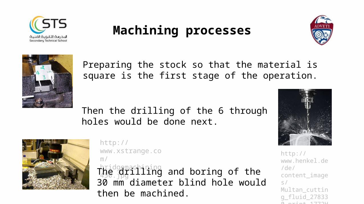
Machining processes
Preparing the stock so that the material is square is the first stage of the operation.
http://www.henkel.de/de/content_images/Multan_cutting_fluid_278330_print_1772H_1772W.jpg
Then the drilling of the 6 through holes would be done next.
http://www.xstrange.com/bridgemachining450.jpgThe drilling and boring of the 30 mm diameter
blind hole would then be machined.

Machining processes continued
By using a slot drill in the milling machine we can machine out the blind slot.
http://www.sandvik.coromant.com/SiteCollectionImages/Technical%20guide/Pablo/D%20milling/091689.jpg
http://grindaix.de/typo3temp/pics/114557b78c.jpg
The perimeter step is machined using an end mill along with the radius corners with the aid of a rotary table.
http://www.berryhillguns.com/mill.jpg
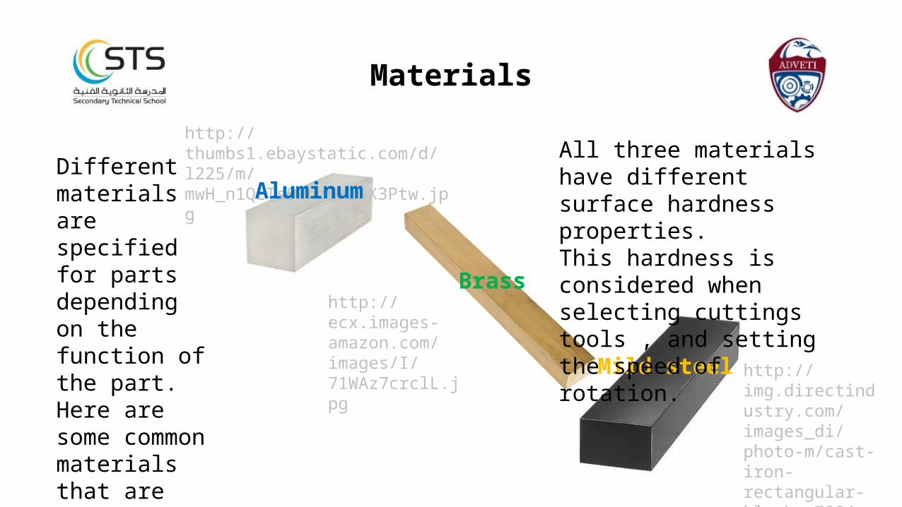
Materials
Different materials are specified for parts depending on the function of the part. Here are some common materials that are machined on a lathe and milling machine.
http://img.directindustry.com/images_di/photo-m/cast-iron-rectangular-blocks-7884-3782031.jpg
http://ecx.images-amazon.com/images/I/71WAz7crclL.jpg
http://thumbs1.ebaystatic.com/d/l225/m/mwH_n1QLTs00hzEx25X3Ptw.jpg
Aluminum
Brass
Mild steel
All three materials have different surface hardness properties.This hardness is considered when selecting cuttings tools , and setting the speed of rotation.
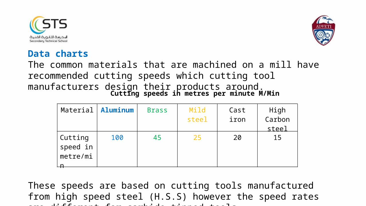
Data chartsThe common materials that are machined on a mill have recommended cutting speeds which cutting tool manufacturers design their products around.
These speeds are based on cutting tools manufactured from high speed steel (H.S.S) however the speed rates are different for carbide tipped tools.
Material Aluminum Brass Mild steel Cast iron High Carbon steel
Cutting speed in metre/min
100 45 25 20 15
Cutting speeds in metres per minute M/Min
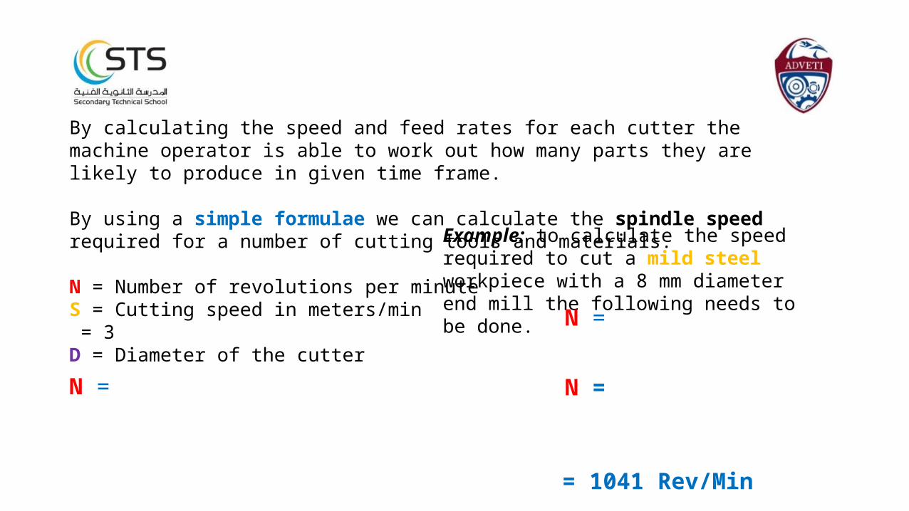
By calculating the speed and feed rates for each cutter the machine operator is able to work out how many parts they are likely to produce in given time frame.
By using a simple formulae we can calculate the spindle speed required for a number of cutting tools and materials.
N = Number of revolutions per minuteS = Cutting speed in meters/min = 3D = Diameter of the cutter
N =
Example: to calculate the speed required to cut a mild steel workpiece with a 8 mm diameter end mill the following needs to be done.
N =
N =
= 1041 Rev/Min
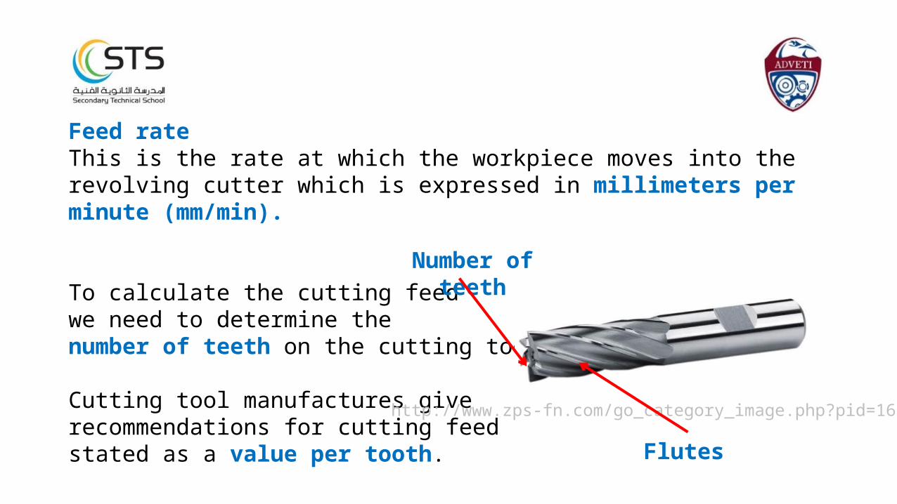
Feed rateThis is the rate at which the workpiece moves into the revolving cutter which is expressed in millimeters per minute (mm/min).
To calculate the cutting feedwe need to determine thenumber of teeth on the cutting tool.
Cutting tool manufactures give recommendations for cutting feed stated as a value per tooth.
Number of teeth
http://www.zps-fn.com/go_category_image.php?pid=166
Flutes

End mill Slot drill Drill bit
Boring cutter
Vertical Cutter types
Thread mill
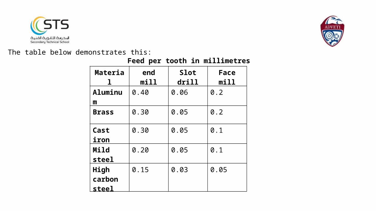
Feed per tooth in millimetresThe table below demonstrates this:
Material end mill Slot drill Face mill
Aluminum 0.40 0.06 0.2
Brass 0.30 0.05 0.2
Cast iron 0.30 0.05 0.1
Mild steel 0.20 0.05 0.1
High carbon steel
0.15 0.03 0.05
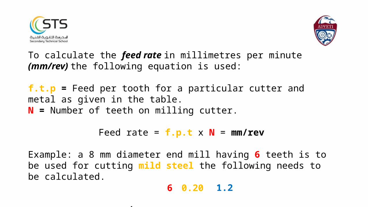
To calculate the feed rate in millimetres per minute (mm/rev) the following equation is used:
f.t.p = Feed per tooth for a particular cutter and metal as given in the table.N = Number of teeth on milling cutter.
Feed rate = f.p.t x N = mm/rev
Example: a 8 mm diameter end mill having 6 teeth is to be used for cutting mild steel the following needs to be calculated.
mm/rev = x = 6 0.20 1.2
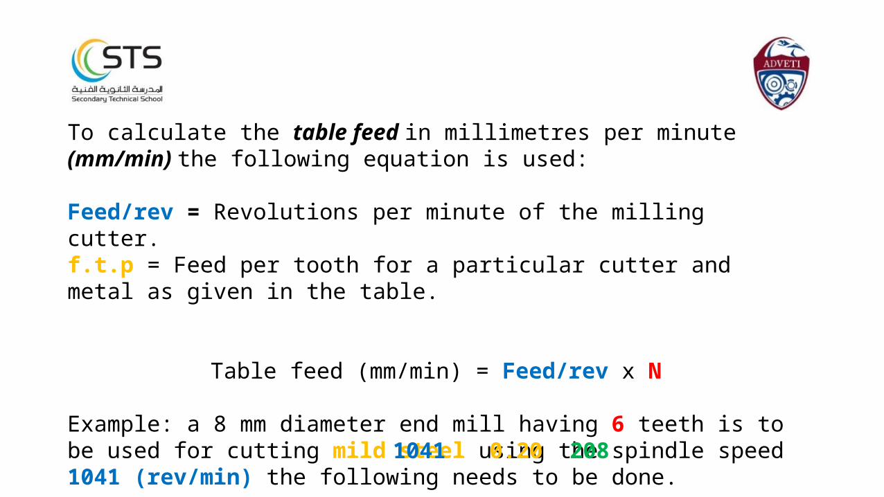
To calculate the table feed in millimetres per minute (mm/min) the following equation is used:
Feed/rev = Revolutions per minute of the milling cutter.f.t.p = Feed per tooth for a particular cutter and metal as given in the table.
Table feed (mm/min) = Feed/rev x N
Example: a 8 mm diameter end mill having 6 teeth is to be used for cutting mild steel using the spindle speed 1041 (rev/min) the following needs to be done.
Table feed = x = 0.20 2081041
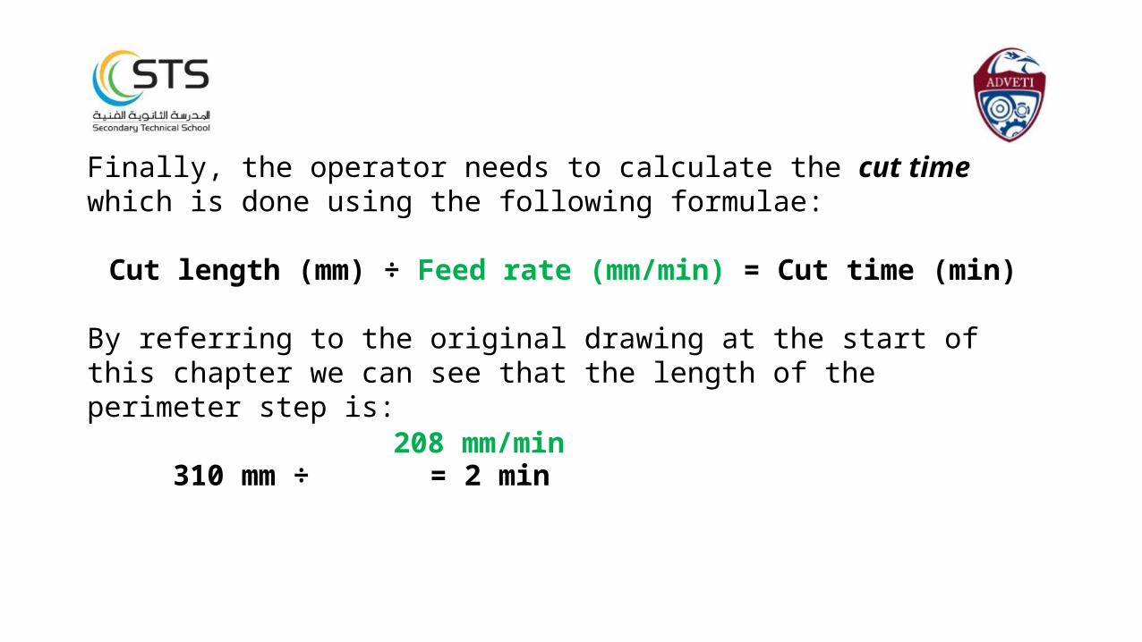
Finally, the operator needs to calculate the cut time which is done using the following formulae:
Cut length (mm) ÷ Feed rate (mm/min) = Cut time (min)
By referring to the original drawing at the start of this chapter we can see that the length of the perimeter step is:
310 mm ÷ = 2 min208 mm/min
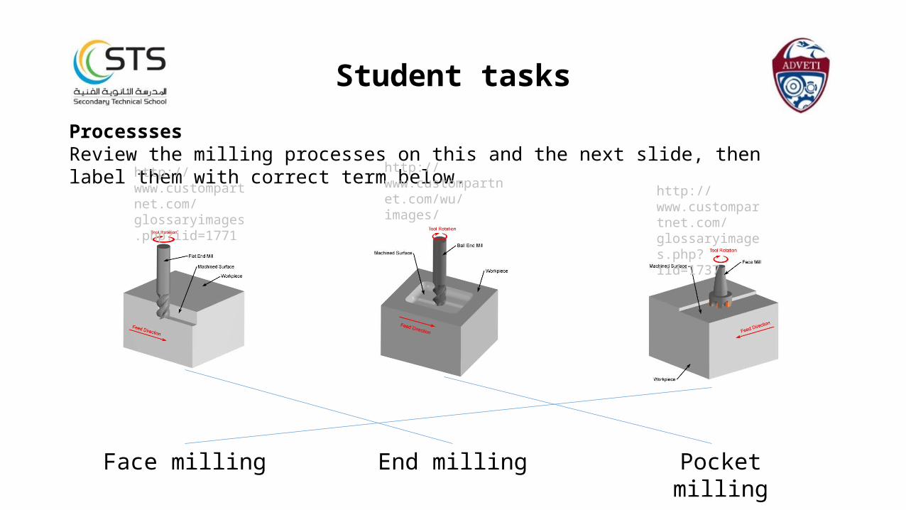
ProcesssesReview the milling processes on this and the next slide, then label them with correct term below.
http://www.custompartnet.com/wu/images/milling/pocket-milling.png
http://www.custompartnet.com/glossaryimages.php?iid=1737
http://www.custompartnet.com/glossaryimages.php?iid=1771
Face milling End milling Pocket milling
Student tasks
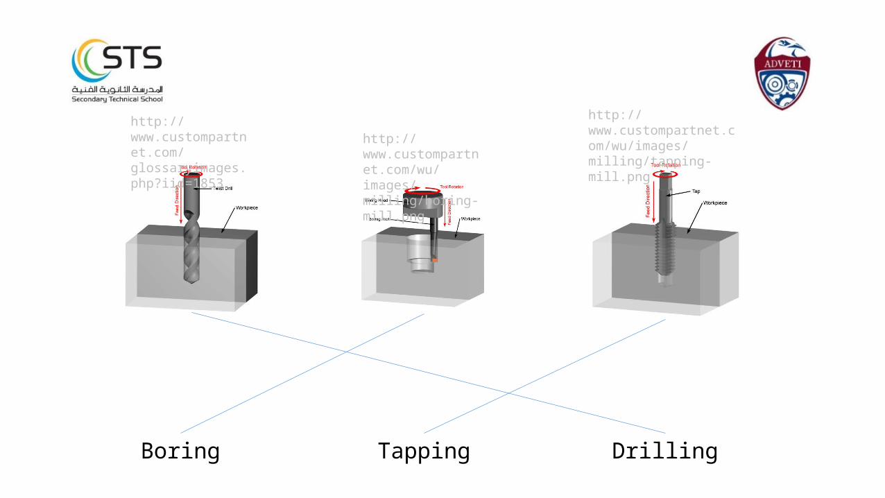
http://www.custompartnet.com/glossaryimages.php?iid=1853
http://www.custompartnet.com/wu/images/milling/boring-mill.png
http://www.custompartnet.com/wu/images/milling/tapping-mill.png
Boring Tapping Drilling

Cutting tool Teeth and flutes
J
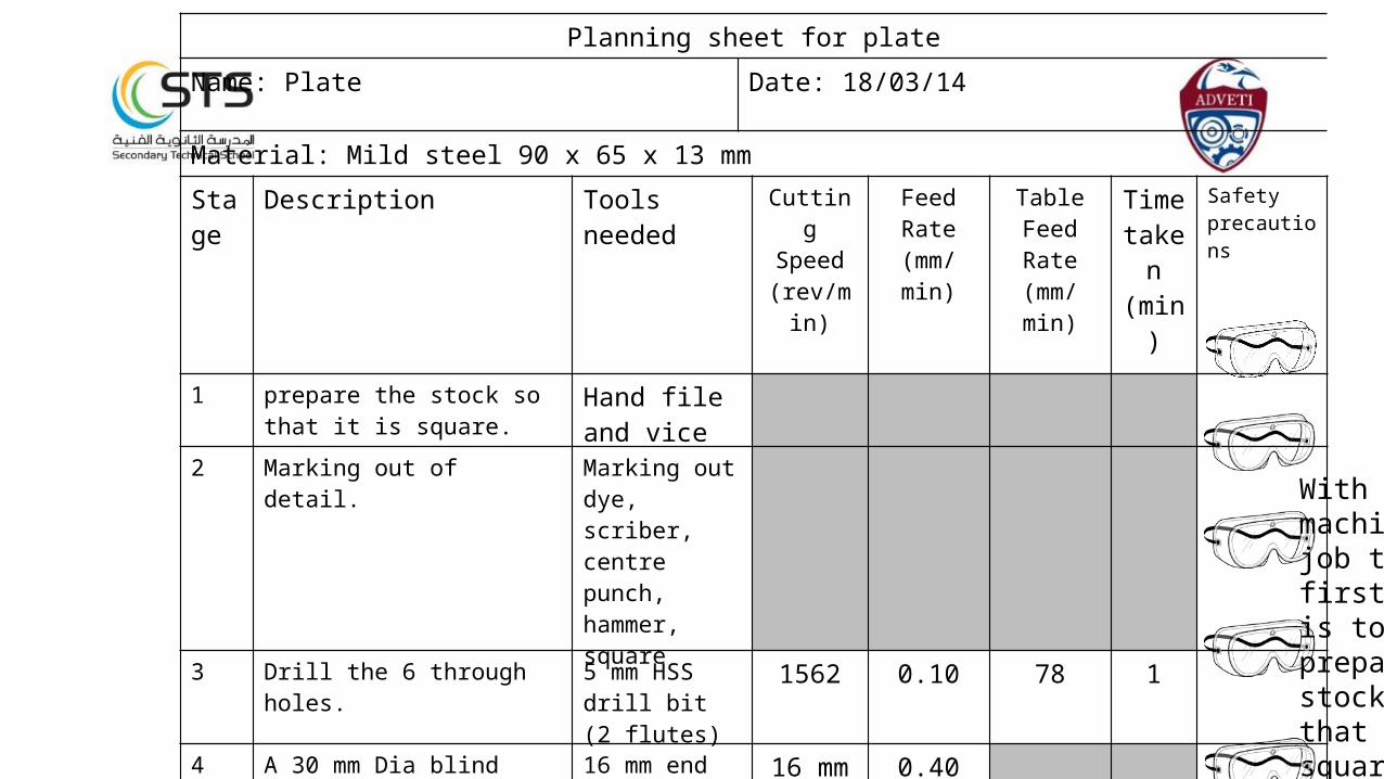
Planning sheet for plate
Name: Plate Date: 18/03/14
Material: Mild steel 90 x 65 x 13 mm
Stage
Description Tools needed CuttingSpeed
(rev/min)
FeedRate
(mm/min)
TableFeedRate
(mm/min)
Time taken(min)
Safety precautions
1 prepare the stock so that it is square.
Hand file and vice
2 Marking out of detail. Marking out dye, scriber, centre punch, hammer, square
3 Drill the 6 through holes. 5 mm HSS drill bit (2 flutes)
1562 0.10 78 1
4 A 30 mm Dia blind hole. 16 mm end mill (2 flutes) then 30 mm boring cutter (1 flute)
16 mm = 500
30 mm = 266
0.40
0.20
5 1 x 3 mm deep slot. 10 mm slot drill (2 flutes
806 0.10 40 1
6 Perimeter step 8 mm end mill (6 flutes)
1000 1.2 200 2
7 Radius corners 8 mm end mill (6 flutes)
1000 1.2 200 1
8 Tapping the 6 through holes M4 tap (2 flutes) Slowest speed
Hand
With any machining job the first stage is to prepare the stock so that it is square using two surfaces.
Chapter 3
Select and mount tools:• 3.1 Select appropriate tools for turning, facing
grooving and milling.
• 3.2 Show how to mount lathe tools and milling cutters.
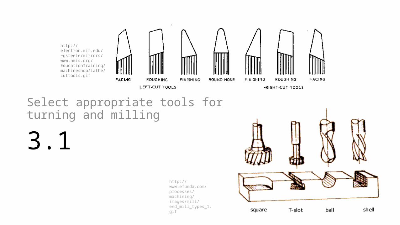
3.1
Select appropriate tools for turning and milling
http://electron.mit.edu/~gsteele/mirrors/www.nmis.org/EducationTraining/machineshop/lathe/cuttools.gif
http://www.efunda.com/processes/machining/images/mill/end_mill_types_1.gif
Introduction
Both the centre lathe and milling machines are universal in their operation.
They can perform several different cutting task. The type of task is determined by the feature requirements of the
component or part being manufactured.The operator can then select or adapt existing cutting tools to suit.
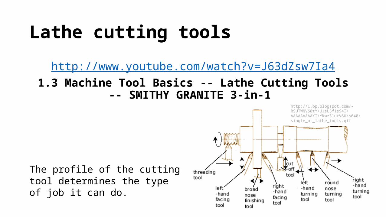
Lathe cutting tools
http://www.youtube.com/watch?v=J63dZsw7Ia41.3 Machine Tool Basics -- Lathe Cutting Tools -- SMITHY GRANITE 3-
in-1
The profile of the cutting tool determines the type of job it can do.
http://1.bp.blogspot.com/-RSUTWNVS8tY/UJsLSf1sS4I/AAAAAAAAAXI/Ykwz51urV6U/s640/single_pt_lathe_tools.gif
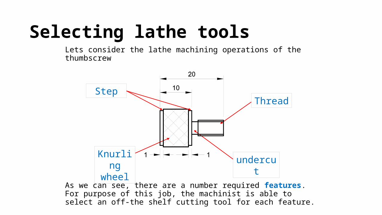
Selecting lathe toolsLets consider the lathe machining operations of the thumbscrew
As we can see, there are a number required features. For purpose of this job, the machinist is able to select an off-the shelf cutting tool for each feature.
Step
Knurlingwheel undercut
Thread
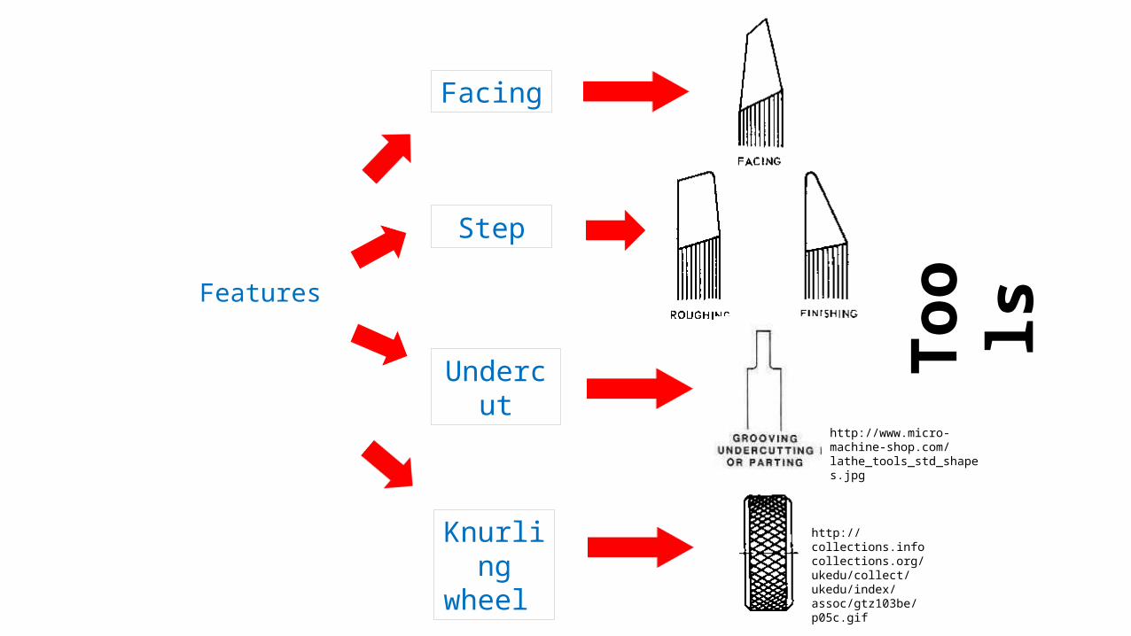
Features
Knurling wheel
Step
Undercut
http://collections.infocollections.org/ukedu/collect/ukedu/index/assoc/gtz103be/p05c.gif
Tool
s
Facing
http://www.micro-machine-shop.com/lathe_tools_std_shapes.jpg
Butt weldShank
Tool bit
Tool holder
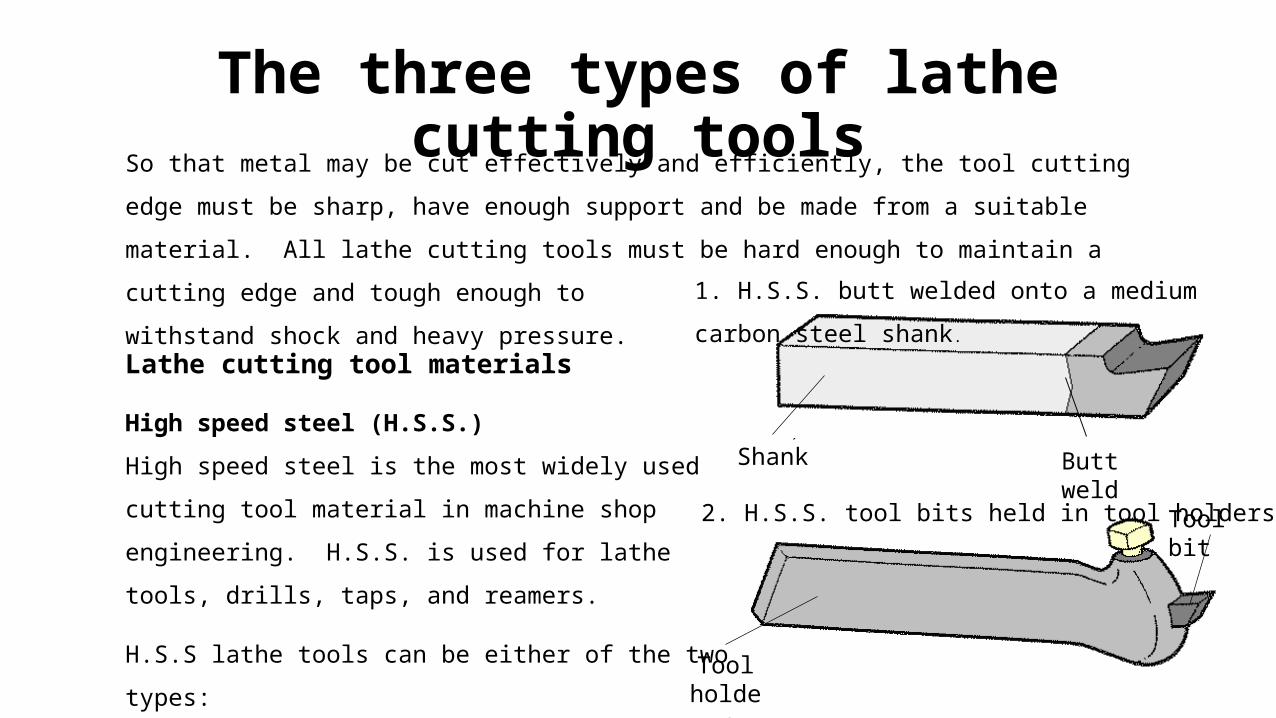
So that metal may be cut effectively and efficiently, the tool cutting edge must be
sharp, have enough support and be made from a suitable material. All lathe cutting
tools must be hard enough to maintain a cutting edge and tough enough to
withstand shock and heavy pressure.
The three types of lathe cutting tools
Lathe cutting tool materials
High speed steel (H.S.S.)
High speed steel is the most widely used cutting
tool material in machine shop
engineering. H.S.S. is used for lathe tools, drills,
taps, and reamers.
H.S.S lathe tools can be either of the two types:
1. H.S.S. butt welded onto a medium carbon
steel shank.
2. H.S.S. tool bits held in tool holders.

Tungsten carbide
This material is very much harder than high
speed steel, so higher cutting speeds are
possible.
The two main types of tungsten carbide tools
are:
1. The insert (tip) is brazed onto the shank.
When the insert is worn, it must be
removed, the tip turned and re-brazed
back onto shank.
Insert
Shank
Braze
2. The tungsten carbide insert is clamped to
the shank. When a cutting edge is worn
the insert can be turned around and
accurately clamped in position so that
another cutting edge can be used.
InsertClamp
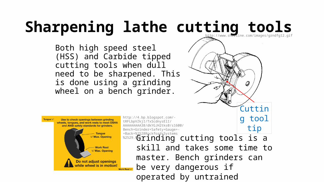
Sharpening lathe cutting toolsBoth high speed steel (HSS) and Carbide tipped cutting tools when dull need to be sharpened. This is done using a grinding wheel on a bench grinder.
Cutting tool tip
Grinding cutting tools is a skill and takes some time to master. Bench grinders can be very dangerous if operated by untrained personnel therefore follow safety guidelines.
http://www.sherline.com/images/grndfg12.gif
http://4.bp.blogspot.com/-tRFLbpVZkjI/TxScdnysElI/AAAAAAAAA38/dkYGJH2tks0/s1600/Bench+Grinder+Safety+Gauge+-+Back+%2528Rockford+Systems%2529.PNG
Scale 1:1 Dim : mmD rn : F r i Date :2/7/07
Matl. 16mm M/S Bar
Note : all dimensions +/- 1mm unless otherwise stated
Tap Wrench
30
100
5
33.5
5
2.5
30
Sectional View (Body)
Plan View (Body)
D9.5
12
D11
185
Tap M8C'Drill D8
20
84
30
D4.5
D11
30
10
Thread M8Sectional View (Handle)
Plan View (Handle)
Knurl Knurl
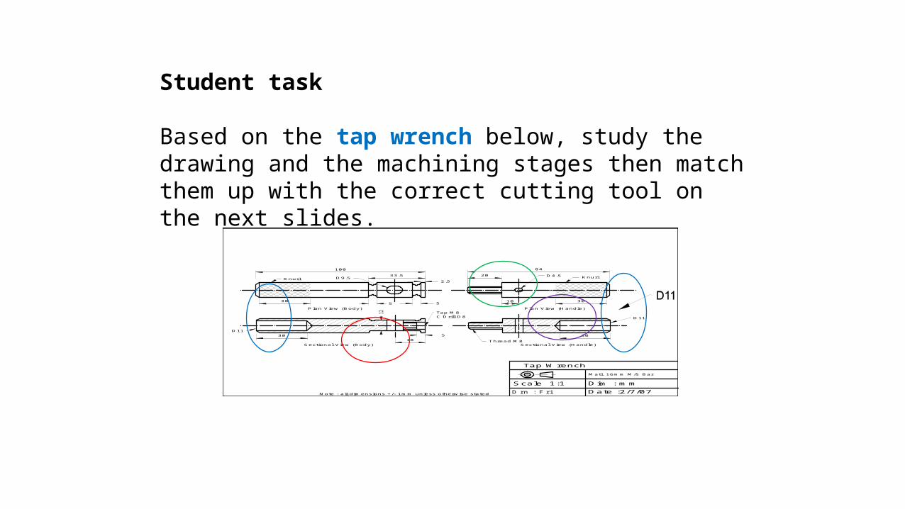
Student task
Based on the tap wrench below, study the drawing and the machining stages then match them up with the correct cutting tool on the next slides.
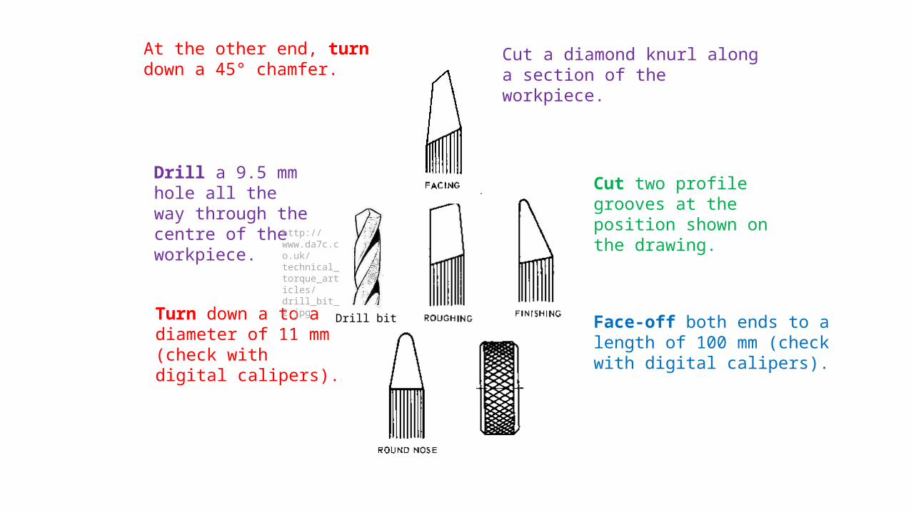
At the other end, turn down a 45° chamfer.
Cut a diamond knurl along a section of the workpiece.
Face-off both ends to a length of 100 mm (check with digital calipers).
Drill a 9.5 mm hole all the way through the centre of the workpiece.
Turn down a to a diameter of 11 mm (check with digital calipers).
Cut two profile grooves at the position shown on the drawing.
http://www.da7c.co.uk/technical_torque_articles/drill_bit_2.jpg
Drill bit

Drill bit
Turn down a to a diameter of 11 mm (check with digital calipers).
Drill a 9.5 mm hole all the way through the centre of the workpiece.
At the other end, turn down a 45° chamfer. Face-off both ends to a length of 100
mm (check with digital calipers).
Cut a diamond knurl along a section of the workpiece.
Cut two profile grooves at the position shown on the drawing.

The milling cutting tool
http://www.youtube.com/watch?v=ckzK-LbeZmY2.2 Machine Tool Basics -- Mill Cutting Tools -- SMITHY GRANITE 3-in-1
Again, the profile of a mill cutting tool determines the type of job it can do. http://electron.mit.edu/
~gsteele/mirrors/www.nmis.org/EducationTraining/machineshop/mill/mcutters.gif
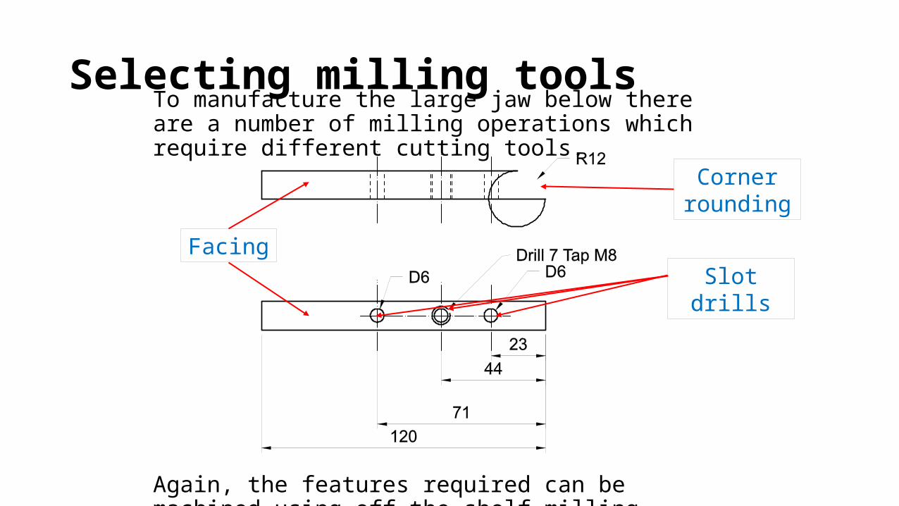
To manufacture the large jaw below there are a number of milling operations which require different cutting tools.
Again, the features required can be machined using off-the-shelf milling cutting tools.
Selecting milling tools
Facing
Corner rounding
Slot drills
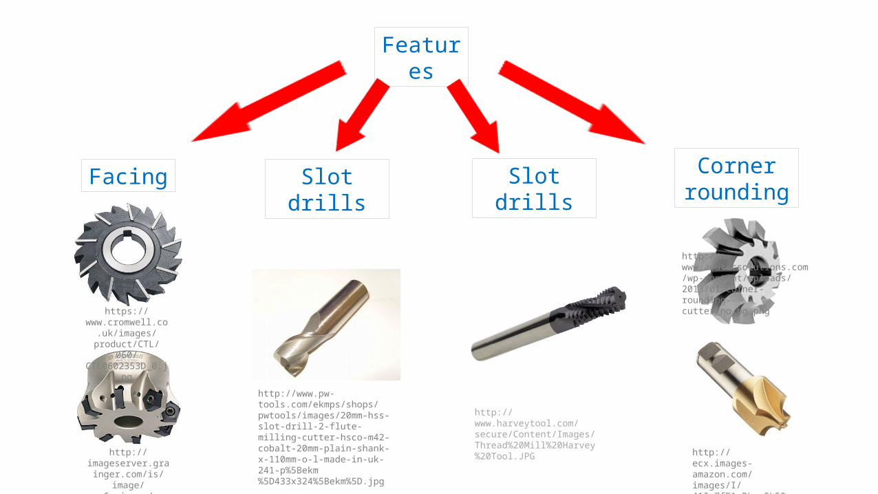
Features
Facing Slot drills Corner rounding
http://imageserver.grainger.c
om/is/image/Grainger/
4RKH4_AS01?$productdetail$
https://www.cromwell.co.uk/images/product/CTL/
060/CTL0602353D_0.jpg
http://www.pw-tools.com/ekmps/shops/pwtools/images/20mm-hss-slot-drill-2-flute-milling-cutter-hsco-m42-cobalt-20mm-plain-shank-x-110mm-o-l-made-in-uk-241-p%5Bekm%5D433x324%5Bekm%5D.jpg
http://ecx.images-amazon.com/images/I/41Im7fE1rBL._SL500_AA300_.jpg
http://www.acutecsolutions.com/wp-content/uploads/2013/01/corner-rounding-cutter_no_bg.png
Slot drills
http://www.harveytool.com/secure/Content/Images/Thread%20Mill%20Harvey%20Tool.JPG
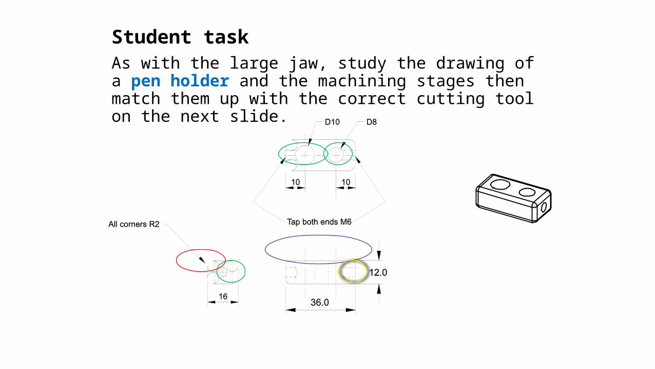
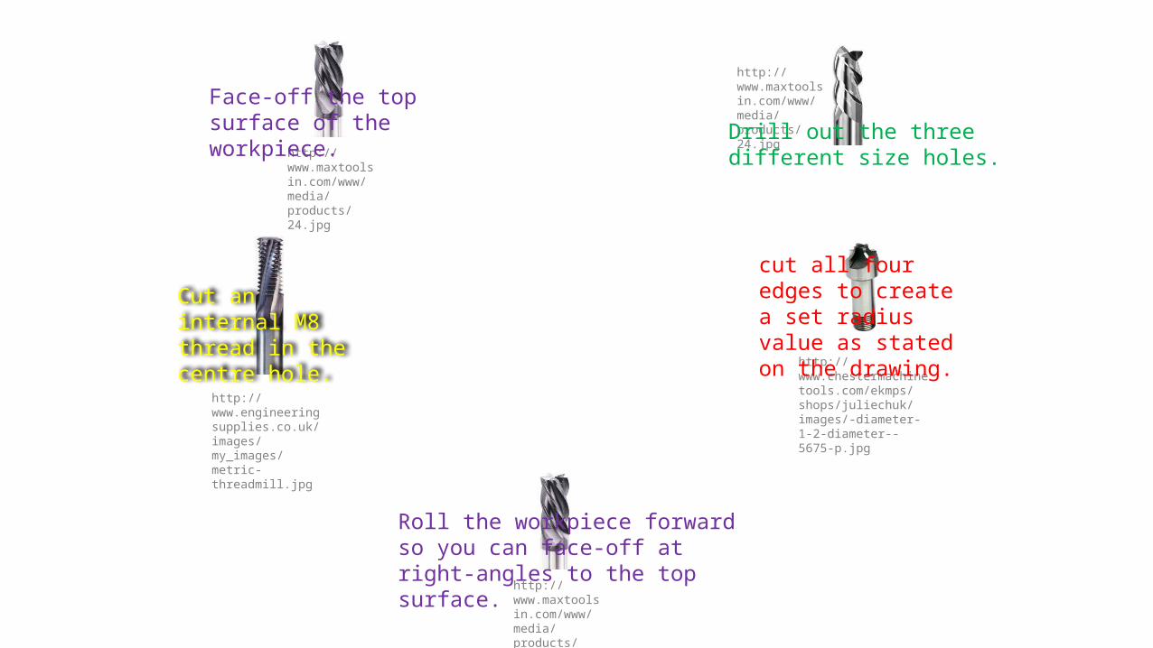
Student taskAs with the large jaw, study the drawing of a pen holder and the machining stages then match them up with the correct cutting tool on the next slide.
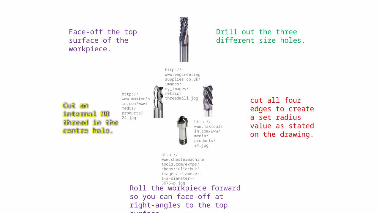
Face-off the top surface of the workpiece.
Roll the workpiece forward so you can face-off at right-angles to the top surface.
Drill out the three different size holes.
cut all four edges to create a set radius value as stated on the drawing.
Cut an internal M8 thread in the centre hole.
http://www.chestermachinetools.com/ekmps/shops/juliechuk/images/-diameter-1-2-diameter--5675-p.jpg
http://www.maxtoolsin.com/www/media/products/24.jpg
http://www.engineeringsupplies.co.uk/images/my_images/metric-threadmill.jpg
http://www.maxtoolsin.com/www/media/products/24.jpg
http://www.maxtoolsin.com/www/media/products/24.jpg
http://www.maxtoolsin.com/www/media/products/24.jpg
http://www.chestermachinetools.com/ekmps/shops/juliechuk/images/-diameter-1-2-diameter--5675-p.jpg
http://www.maxtoolsin.com/www/media/products/24.jpg
http://www.engineeringsupplies.co.uk/images/my_images/metric-threadmill.jpg
Face-off the top surface of the workpiece.
Roll the workpiece forward so you can face-off at right-angles to the top surface.
Drill out the three different size holes.
cut all four edges to create a set radius value as stated on the drawing.
Cut an internal M8 thread in the centre hole.
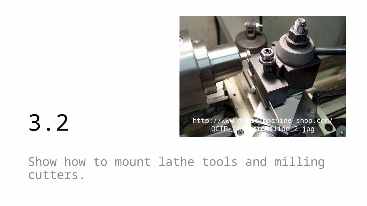
3.2
Show how to mount lathe tools and milling cutters.
http://www.micro-machine-shop.com/QCTP_14mm_crosslide_2.jpg
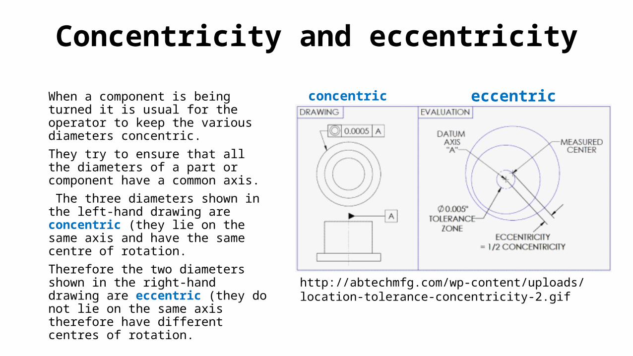
When a component is being turned it is usual for the operator to keep the various diameters concentric. They try to ensure that all the diameters of a part or component have a common axis. The three diameters shown in the left-hand drawing are concentric (they lie on the same axis and have the same centre of rotation.Therefore the two diameters shown in the right-hand drawing are eccentric (they do not lie on the same axis therefore have different centres of rotation.
http://abtechmfg.com/wp-content/uploads/location-tolerance-concentricity-2.gif
Concentricity and eccentricity
concentric eccentric

Introduction
In order to cut a workpiece accurately there are a number of factors that need to be followed:
The position of the cutting tool in the toolpost.Centre the cutting edge.The safe setup of the cutting tool.
http://www.frets.com/HomeShopTech/Tooling/ToolHeightSet/toolheightset.jpg
http://www.poolewood.co.uk/acatalog/474644.jpg
http://www.tacrockford.com/images/accessories/LatheChuckShieldsHeader.jpg

The position of the cutting tool
In most turning applications the cutting tool needs to be perpendicular to the workpiece.
There are a number of toolpost types which are used to accommodate different cutting tools. The most popular one is the ‘quick-change’ toolposts as seen above.
To avoid inaccurate cutting and deflection, the cutting tool needs to be secured tight in the toolpost.
Cutting tool
Screws clamp
the tool
http://www.robotroom.com/DualFan/ButtonTurning.jpg
http://www.youtube.com/watch?v=VkeW_Bcwj3ELathe Tool Post

Setting tool on centre heightTo maintain the rake and clearance angles on the lathe tool, it is important that the tool is set to centre height. If the tool is set above or below centre height, then rake and clearance angles will change and affect the cutting action.
The overhang of the cutting tool should be kept to a minimum to avoid vibration of the tool when cutting.
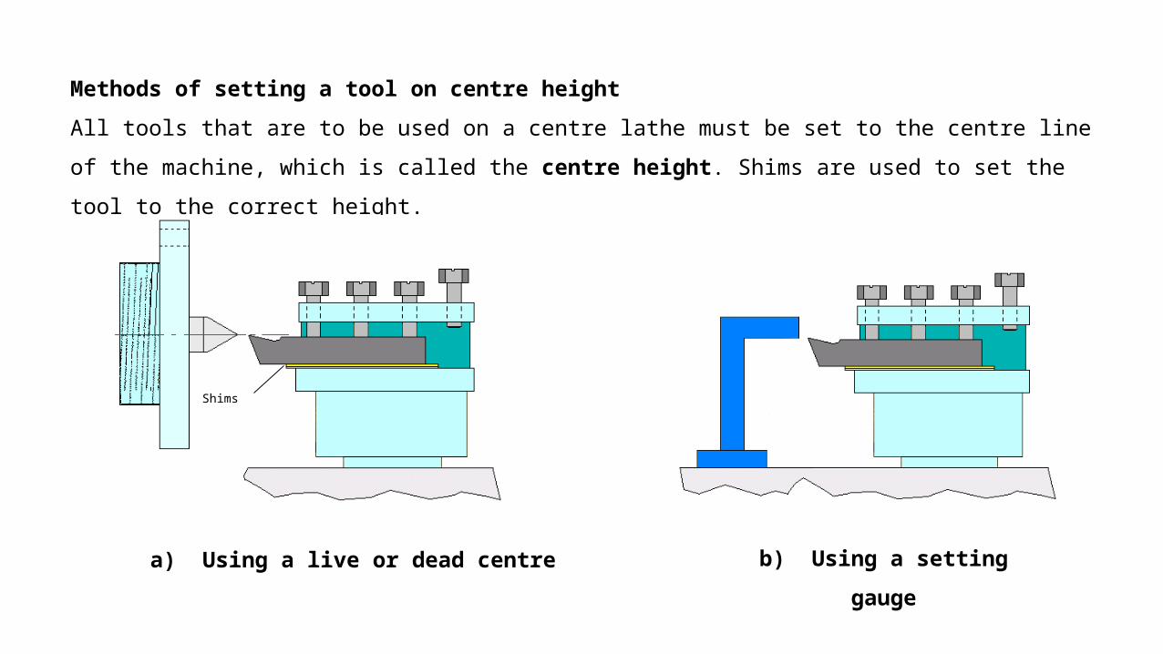
Methods of setting a tool on centre height
All tools that are to be used on a centre lathe must be set to the centre line of the machine,
which is called the centre height. Shims are used to set the tool to the correct height.
a) Using a live or dead centre
Shims
b) Using a setting
gauge
Shims
http://i200.photobucket.com/albums/aa294/oldtiffie/Lathe_misc/Lathe_tool-post1.jpg
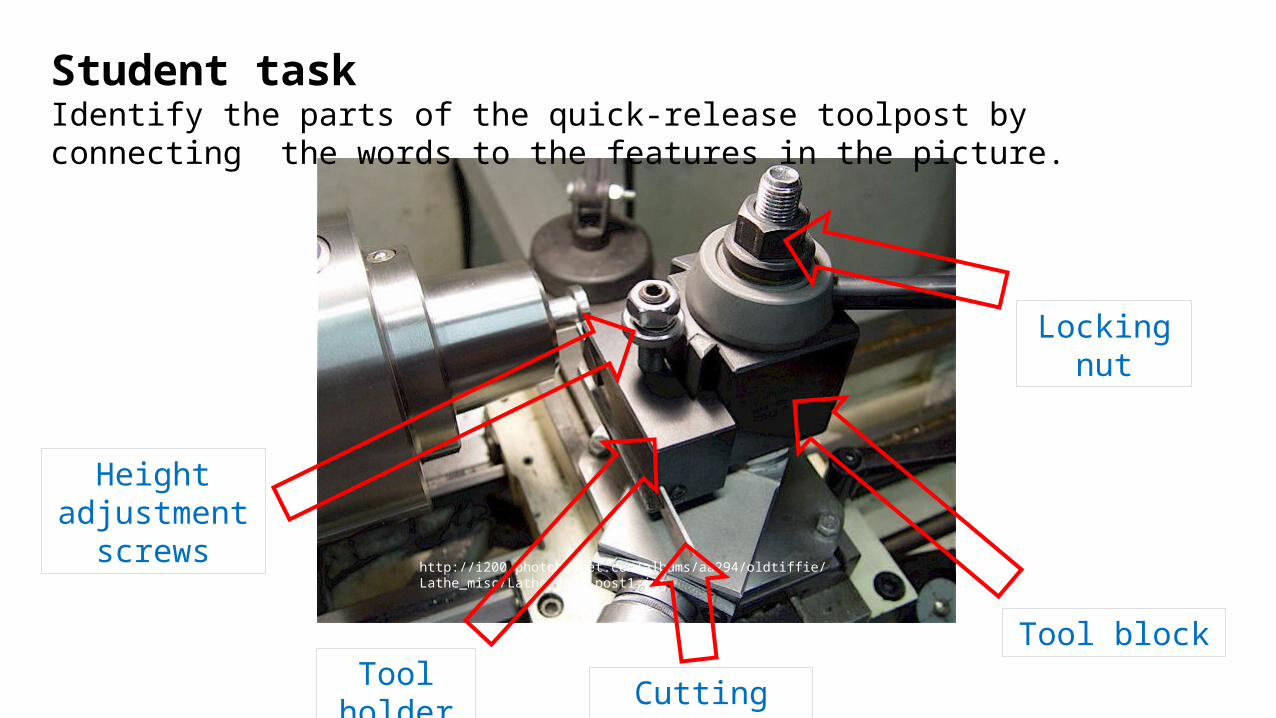
Student taskIdentify the parts of the quick-release toolpost by connecting the words to the features in the picture.
Height adjustment
screws
Tool block
Locking nut
Cutting toolTool holder
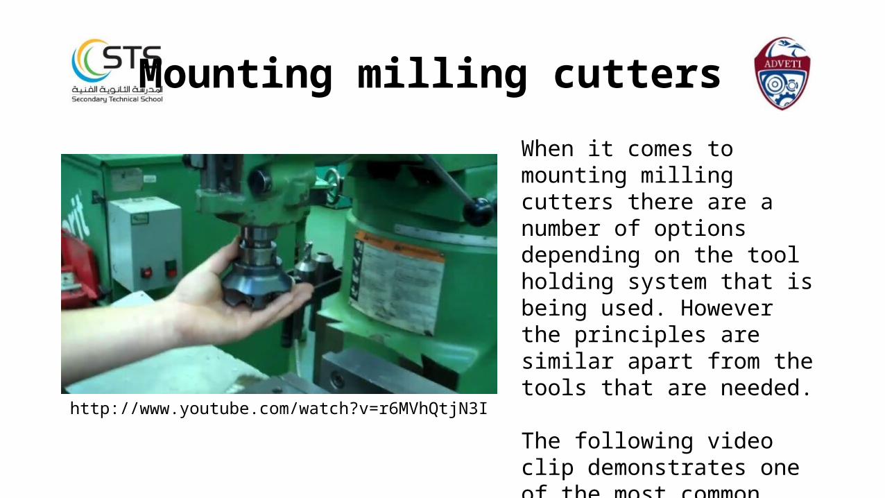
When it comes to mounting milling cutters there are a number of options depending on the tool holding system that is being used. However the principles are similar apart from the tools that are needed.
The following video clip demonstrates one of the most common ways of mounting milling cutters.
http://www.youtube.com/watch?v=r6MVhQtjN3I
Mounting milling cutters
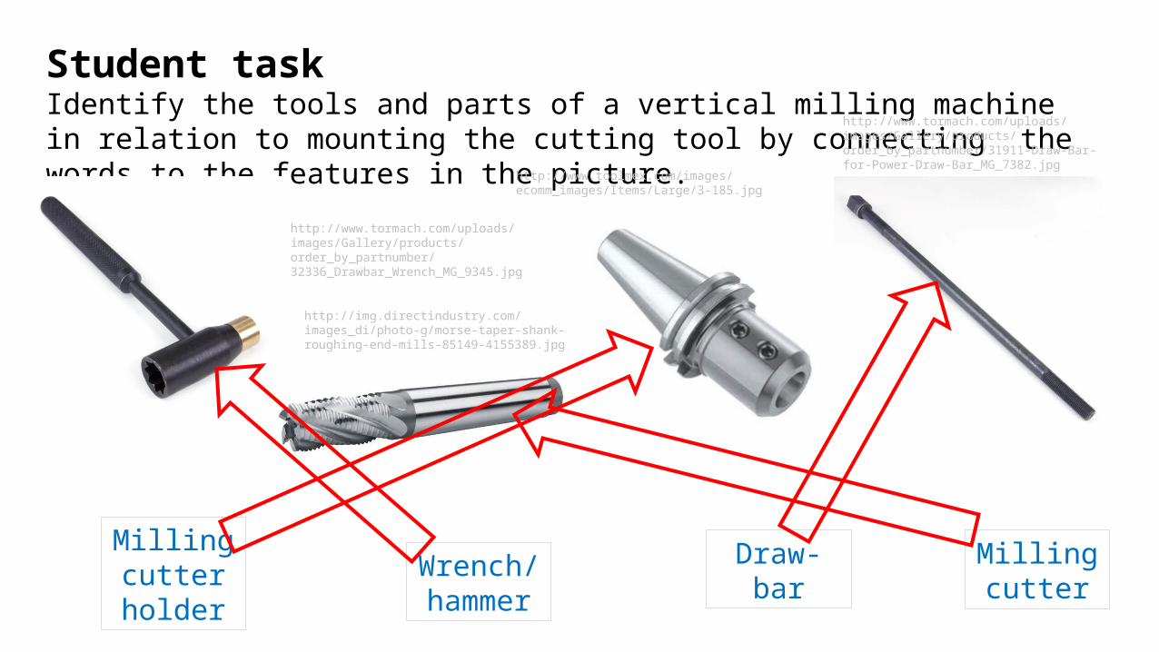
Student taskIdentify the tools and parts of a vertical milling machine in relation to mounting the cutting tool by connecting the words to the features in the picture.
http://www.tormach.com/uploads/images/Gallery/products/order_by_partnumber/32336_Drawbar_Wrench_MG_9345.jpg
http://www.tormach.com/uploads/images/Gallery/products/order_by_partnumber/31911-Draw-Bar-for-Power-Draw-Bar_MG_7382.jpg
http://img.directindustry.com/images_di/photo-g/morse-taper-shank-roughing-end-mills-85149-4155389.jpg
http://www.toolmex.com/images/ecomm_images/Items/Large/3-185.jpg
Milling cutter
Draw-barWrench/hammer
Milling cutter holder
Chapter 4
Perform lathe machining operations(Intermediate)
4.1 Select from a data table, an appropriate feedrate and speed for a given workpiece and tool type.4.2 Secure a workpiece in the lathe chuck and demonstrate lathe machining operations for general turning, taper turning, grooving and parting. Make sure that machining is performed in a safe
manner utilising all guards, safety procedures and personal protective clothing and equipment.
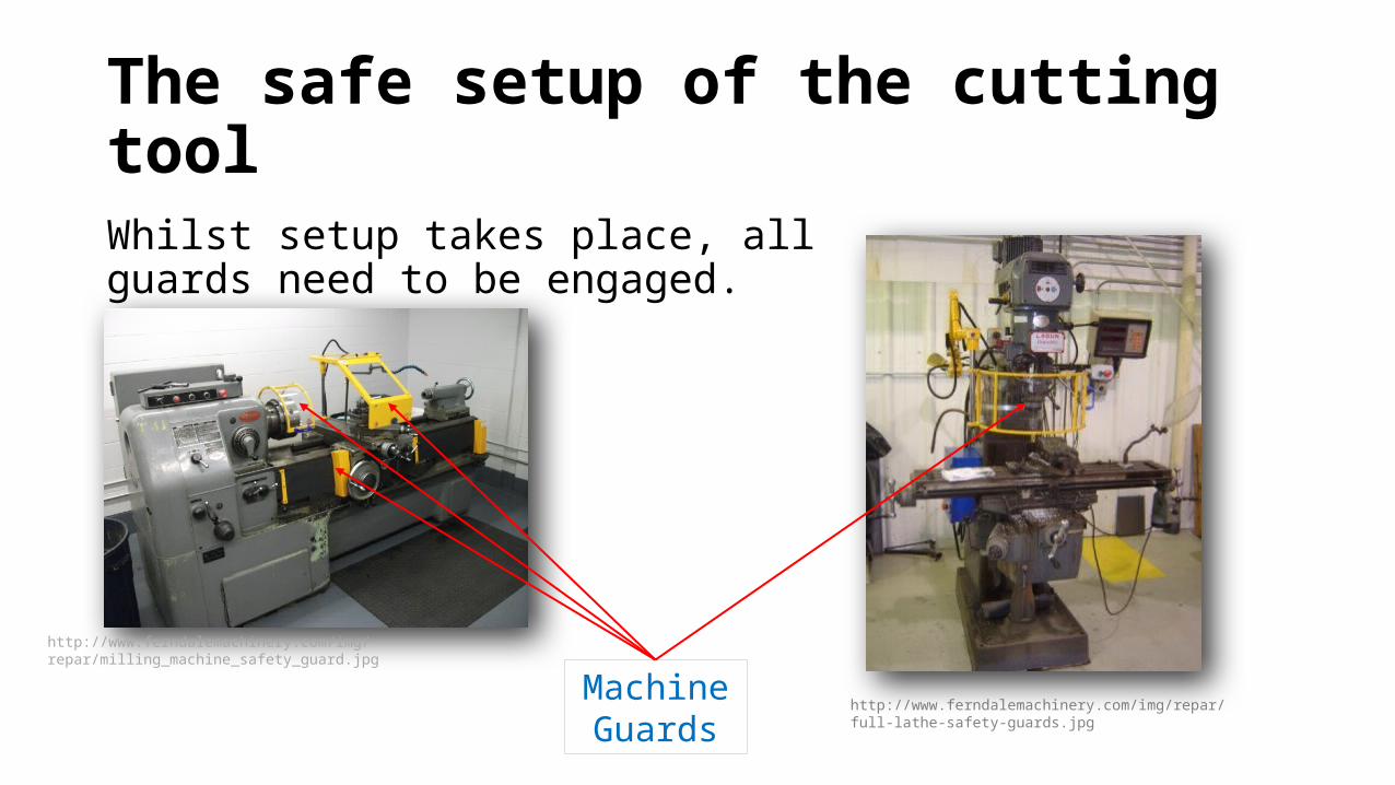
The safe setup of the cutting toolWhilst setup takes place, all guards need to be engaged.
http://www.ferndalemachinery.com/img/repar/full-lathe-safety-guards.jpg
Machine Guards
http://www.ferndalemachinery.com/img/repar/milling_machine_safety_guard.jpg