machine vision methods in computer gamessirkan.iit.bme.hu/~szirmay/machinevision.pdfmachine vision...
TRANSCRIPT
Machine Vision Methods in Computer Games
Laszlo Szirmay-Kalos?
BME IIT
Abstract. This paper surveys machine vision and image processingmethods that can be used in games and also shows how machine vi-sion applications may benefit from the graphics hardware developed forgame applications. By observing image space rendering algorithms, wecome to the conclusion that image processing and rendering methodsrequire similar algorithms and hardware support.
1 Introduction
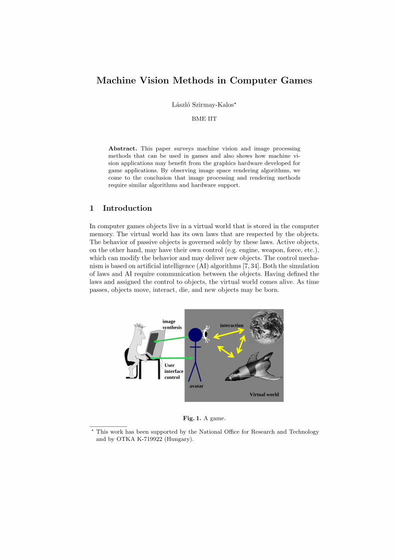
In computer games objects live in a virtual world that is stored in the computermemory. The virtual world has its own laws that are respected by the objects.The behavior of passive objects is governed solely by these laws. Active objects,on the other hand, may have their own control (e.g. engine, weapon, force, etc.),which can modify the behavior and may deliver new objects. The control mecha-nism is based on artificial intelligence (AI) algorithms [7, 34]. Both the simulationof laws and AI require communication between the objects. Having defined thelaws and assigned the control to objects, the virtual world comes alive. As timepasses, objects move, interact, die, and new objects may be born.
Virtual world
avatar
Userinterfacecontrol
imagesynthesis interaction
Fig. 1. A game.
? This work has been supported by the National Office for Research and Technologyand by OTKA K-719922 (Hungary).

2 Szirmay-Kalos
In order to immerse the human user (player) into this virtual world, a specialobject called the avatar is defined (Figure 1). This object is similar to otherobjects with two exceptions. It does not have AI, but its control is connected tothe user interface. On the other hand, the scene is rendered regularly from thepoint of view of the avatar and the image is presented on the computer scene.The user feels “presence” in the virtual world if he is informed about all changeswithout noticeable delay, i.e. at least 20 image frames are generated in everysecond, which is perceived as a continuous motion.
Apart from AI, game development should solve the following tasks:
– Modeling involves the description of the graphical properties of objects, likegeometry, texture, and material.
– Animation definition specifies animation properties, like dynamic parame-ters, skeleton, keyframes, deformation targets, etc. Animation also includesthe description of laws of the virtual world, which are usually, but not neces-sarily, the simplifications of physics laws, such as Newton’s laws, collisions,impulse conservation, etc.
– Simulation of the world, including executing AI algorithms, enforcing thelaws, and animating the world.
– User interfacing is responsible for controlling the avatar according to useractions.
– Rendering the scene from the point of view of the avatar.
Modeling and Animation definition are off-line tasks, while Simulation, Userinterfacing, and Rendering should be executed on-line at least 20 times per sec-ond. This imposes severe requirements on the computer, especially on its render-ing functionality. Rendering needs to identify the surfaces visible from the avatarin different directions (i.e. in different pixels) and compute the radiance spec-trum of the surface. Visibility calculation can be “image centric” when we takepixels one-by-one, trace a ray through this pixel and retain the ray-surface inter-section closest to the avatar. Visibility calculation can also be “object centric”when objects are projected onto the screen one-by-one and their color is mergedinto the evolving image always keeping the color of the closest surfaces. Thefirst approach is called ray tracing, the second is incremental rendering. Graph-ics processors (GPU ) implement incremental rendering and by today have havereached the performance of supercomputers.
This paper reviews the machine vision and image processing aspects of gamedevelopment. On the one hand, we show in which phases of game developmentthese techniques can be used. On the other hand, we also discuss how machinevision applications may benefit from the graphics hardware developed for gameapplications. The organization of the paper is as follows. In Section 2 we presentthe architecture and the programming model of current GPUs. In Section 3 visiontechniques aiming at off-line modeling and animation are discussed. Section 4reviews vision based game interfaces. Finally, in Section 5 we incorporate imageprocessing algorithms into the rendering process. Starting from image process-ing, continuing with deferred shading, we finally discuss image space renderingalgorithm that are conceptually very similar to image processing.

Machine Vision Methods in Computer Games 3
2 Architecture and programming models of GPUs
By today, the GPU has become a general purpose stream processor. If we wish toexploit the computational power of GPUs we can use two programming models(Figure 2).
– Shader APIs mimic the incremental rendering process including both fixedfunction and programmable stages, which can be controlled through a graph-ics API (Direct3D or OpenGL).
– Multi-processor model that presents the GPU as a large collection of mainlySIMD type parallel processors, but hides the fixed function units (e.g. themerging functionality). CUDA1 is the most famous such library. Addition-ally, we may use ATI Stream SDK 2, OpenCL3, and the compute shader inDirectX 11.
vertex buffer
Transform
Clipping + Rasterization +interpolation
Texturing
Compositing (Z-buffer, transparency)
Texturememory
vert
ices
tria
ngle
spi
xels
GeometryShader
VertexShader
FragmentShader
Frame buffer
CPU
GPU
Shader 4 programming model CUDA
Fig. 2. GPU programming models for shader APIs and for CUDA.
In the followings, we discuss the Shader API model, which can be seen as anincremental rendering pipeline implementation with programable stages [32].
Every object of the virtual world is defined as a triangle mesh in its ownmodeling space, thus the virtual world description should be tessellated to a setof triangle meshes. Triangles output by the tessellation are defined by triplets ofvertices, and usually include the normal vector of the surface before tessellation1 [http://www.nvidia.com/object/cuda home.html]2 [http://ati.amd.com/technology/streamcomputing/sdkdwnld.html]3 [http://www.khronos.org/opencl/]

4 Szirmay-Kalos
at the vertices, and optical material parameters, or a texture address that refer-ences values of the same parameters stored in the texture memory. The trianglelist defined by vertices associated with surface characteristics is the input of theincremental rendering process and is stored in the vertex buffer .
The vertex shader gets the vertices one by one. Vertex positions and normalsare transformed to world space where the camera and lights are specified. Makingthis transformation time dependent, objects can be animated. Then, the cameratransformation translates and rotates the virtual world to move the camera tothe origin of the coordinate system and to get it to look parallel to axis z.Perspective transformation, on the other hand, distorts the virtual world in away that viewing rays meeting in the virtual camera become parallel to eachother. It means that after perspective transformation, the more complicatedperspective projection of the camera can be replaced by simple parallel projection.Perspective transformation warps the viewing pyramid to be an axis alignedclipping box that is defined by inequalities −1 < x < 1, −1 < y < 1, and0 < z < 1 (or −1 < z < 1).
Triangles formed by three vertices are processed by the geometry shader,which may change the topology and emit an arbitrary number of triangles in-stead. Typical applications of the geometry shader is on-line geometry smoothing[2], detail geometry addition [33] or geometry synthesis [20].
The fixed function clipping unit clips to the clipping box to removes thoseparts that fell outside of the viewing pyramid. Taking into account the resolutionand the position of the viewport on the screen, a final transformation step,called viewport transformation scales and translates triangles to screen space.In screen space the projection onto the 2D camera plane is trivial, only theX, Y coordinates should be kept from the X, Y, Z triplet. The Z coordinate ofthe point is in [0, 1], and is called the depth value. The Z coordinate is usedby visibility computation since it decides which point is closer to the virtualcamera if two points are projected onto the same pixel. In screen space everyprojected triangle is rasterized to a set of pixels. When an internal pixel is filled,its properties, including the depth value and shading data, are computed viaincremental linear interpolation from the vertex data.
The fragment shader computes the final color from the interpolated data.Besides the color buffer memory (also called frame buffer), we maintain a depthbuffer , containing screen space depth, that is the Z coordinate of the point whosecolor value is in the color buffer. Whenever a triangle is rasterized to a pixel, thecolor and the depth are overwritten only if the new depth value is less than thedepth stored in the depth buffer, meaning the new triangle fragment is closerto the viewer. This process is commonly called the depth buffer algorithm. Thedepth buffer algorithm is also an example of a more general operation, calledmerging , which computes the pixel data as some function of the new data andthe data already stored at the same location.
To make more use of a computed image, it can be directed to the texturememory, and used as an input texture in future rendering passes. While the framebuffer allows just 8-bit data to be stored, textures can hold floating point num-

Machine Vision Methods in Computer Games 5
bers. With this feature some passes may perform general purpose computations,write the results to textures, which can be accessed later in a final gathering step,rendering to the frame buffer. The frame buffer or the texture memory, which iswritten by the fragment shader and the merging unit, is called the render target .
2.1 Image processing on the GPU through shader API
Image processing is a Single Algorithm Multiple Data (SAMD) method, wherethe input is a two-dimensional array L(X, Y ) and the output is another arrayL(X, Y ) which might have a different resolution. For every output pixel X, Y ,the same algorithm A should be executed independently of other output pixels.
In order to execute image processing on the GPU, a single viewport sized quadneeds to be rendered, which covers all pixels of the screen. The viewport is setaccording to the required resolution of the output. In normalized device space,the viewport sized quad is defined by vertices (−1,−1, 0), (−1, 1, 0), (1, 1, 0),(1,−1, 0). Thus this quad needs to be sent down the pipeline, and the fragmentshader program should implement algorithm A.
The most time consuming part of image processing is fetching the inputtexture memory. To reduce the number of texture fetches, we can exploit thebi-linear interpolation feature of texture units, which takes four samples andcomputes a weighted sum requiring the cost of a single texture fetch [13].
Classic image processing libraries and algorithms have already been portedto the GPU [25]. A good collection of these is the GPGPU homepage4, whichhas links to photo-consistency, Fourier transform, stereo-reconstruction, fractalimage compression, etc. solutions.
2.2 Image processing with CUDA
CUDA presents the GPU as a collection of (1..128) multi-processors, that cancommunicate with each other through a not-chaced (i.e. slow) global memory.A single multi-processor has many (e.g. 256) scalar processors that can be syn-chronized and are interconnected by fast memory. Scalar processors form groupsof 32 (called warps) that share the same instruction unit, thus they perform thesame instruction in a SIMD fashion.
Many different vision and image processing applications have been imple-mented on this massively parallel hardware. The CUDA homepage includes theGpuCV vision library, tomographic reconstruction, optical flow, motion tracing,sliding-window object detection, Canny edge detection, etc.
3 Vision techniques in modeling and animation
An obvious application of vision methods would be the automatic reconstruc-tion of simpler virtual objects from real objects using, for example, stereo vision
4 [http:gpgpu.org]

6 Szirmay-Kalos
or photo-consistency [37, 15]. While these approaches are viable in engineering,commerce, archeology, etc. they are not popular in game development. The rea-son is that games have very special expectations toward the generated meshes.They should be “low-poly” i.e. should consist of minimal number of vertices,should be artifact free, and should be smoothly deformed during morphing andskeleton animation. Unfortunately, vision based reverse engineering techniques[37] cannot compete with the efficiency of modeling tools and the experience ofprofessional human modelers.
However, vision based methods are clearly the winners in natural phenom-ena modeling and in animation definition, which are too complex for humanmodelers.
3.1 Image based modeling and animation
The real world has objects of enormous complexity, which would be very difficultto model or simulate. Thus, we steal from the real world, and take images andvideos from real-world phenomena and include them into the game. However,putting a 2D image somewhere into the 3D virtual world would be too obviouscheating since the 2D image cannot provide the same motion parallax that weare used to in the 3D world. A few notable exceptions are the cases when theobject is very large and very far, like the sky or distant stars, etc.
The missing view parallax can be restored approximately by billboards thatalways rotate towards the avatar, with the application of multiple images tex-tured on an approximate geometry [8], or using image based rendering [18, 11]that are equivalent to digital holograms. However, these techniques still lack thecontrollability of the object itself. What we really need is a method that takesthe image as an example and automatically constructs a model from it, whichcan, among others, deliver this particular object, but is also capable of producingmany other, similar objects.
Conceptually, we may use the input image as the basis of determining theparameters of a model. Suppose, for example, that we are modeling a cloud. Weknow the operation of the cloud (Navier-Stokes equations) and how it should berendered (radiative transfer equation), but we do not know the internal param-eters. In this case, a reverse-engineering approach should be taken that fits themodel onto the image sequence [21].
Another approach is the example based synthesis that decomposes the inputto low-frequency and high-frequency components. The low-frequency compo-nents that are responsible for the general behavior are redefined by the modeler.However, the complicated high-frequency components are ported to the newmodel, including scaling and normalization as well. In order to separate impor-tant features, Principal Component Analysis (PCA) has proven to be successful.Individual examples are interpreted as a collection of numbers, i.e. points inhigh-dimensional spaces. PCA finds a subspace spanned by eigenvectors. Mod-ifying the coordinates with respect to the eigenvectors, an infinite collection ofnew objects can be obtained [3]. Example based methods have been successful in

Machine Vision Methods in Computer Games 7
texture synthesis [16], animating still images [39], geometry synthesis [22], andbuilding generation [24].
....
Video clip (3D texture)Frame 1 Frame 2 Frame n
Particle 1 Particle 2 Particle 3 .... Virtual explosion
Fig. 3. Explosion rendering when the high-frequency details are added from a video.
Now we take the example of explosion rendering, where a few particles aresimulated according to the laws of physics [36]. However, when the system isrendered, we take a video from a real explosion, and its sample parts are usedto modulate the temperature variations of the simulated explosion (Figure 3).
3.2 Motion capture based animation
Motion capture animation is the most common technique in games because manyof the subtle details of human motion are naturally present in the data that wouldbe difficult to model manually.
Traditionally, only finite number of markers attached to joints are followedby stereo-vision techniques (left of Fig. 4). However, this requires special setupand cannot follow garment motions. Markerless techniques that usually processsilhouette images can even handle garment deformations, but are much moredifficult to implement and less robust [38] (right of Fig. 4). We note that markerbased motion caption is also important in medical applications [40]. Researchhas also focused on techniques for modifying and varying existing motions [10].
4 Vision based game interfaces
In today’s games, the common goal is creating user interfaces where the userfeels the “immersion” of the virtual world. Obviously, bodily user interfacesare more natural than using just the keyboard or mouse. Although intensiveresearch has been executed in this area, the mass market remained unchangedfor a longer time, because the developed systems were too cumbersome to useand very expensive. The first, really revolutionary device showed up in 2006when the Wiimote5 controller was introduced. With a three-axis accelerometer,5 [http://www.wii.com/]

8 Szirmay-Kalos
Motion capture with markers Motion capture with silhouettes
Skeleton-animatedcharacter
Fig. 4. Motion capture that follows markers attached to joints (left) and followingsilhouettes [27] (right).
distance sensing (via the Sensor Bar), and a simple BlueTooth interface, theWiimote controller offered developers the opportunity to create many differenttypes of novel interfaces [29].
The other promising direction is the inclusion of one or more cameras inthe game system and to use its images to control the avatar [17]. We may notethat a similar problem is investigated in presentation control (i.e. Powerpointpresentation) as well [1]. In this respect, vision based user interfacing is similarto vision based animation modeling. However, there are critical differences. Inuser interfacing, the algorithms must be real-time, robust, but neither precisecalibration nor special clothing, lighting, markers etc. are allowed. This makesthese methods really challenging.
The camera is placed in front of the user who can control the applicationaction with his body movements [14]. Today there are also several commercialcamera based body-driven game systems available, e.g. the Mandala GX Systemby Vivid Group6 and Eyetoy7.
Almost all computer vision approaches rely on tracking to analyze human mo-tion from video input [9]. In general, these systems assume accurate initializationand then track changes in pose based on an articulated 3D human model. Fromthe cameras we get synchronized images. For each camera image, the backgroundis subtracted and only the foreground character image is kept. The silhouettefor each viewpoint corresponds to a cone of rays from the camera through allpoints of the objects. The intersection of these cones is the approximation of theobject’s volume. A volumetric representation, e.g. a voxel array, can be easilyderived from the images. Each voxel center is projected onto each camera image,and we check whether or not the projection is a foreground pixel. If it is forall camera images, then the voxel belongs to the object, otherwise, the voxel isoutside of the object.
6 [http://www.vividgroup.com/]7 [http://www.fmod.org/]

Machine Vision Methods in Computer Games 9
Suppose we have an articulated model, i.e. a mesh with a skeleton and bind-ing, which defines the degree of freedom for the model and also the possibledeformations. The task is then to find the rotation angles in the joints to matchthe model to the approximate volume of the measured object. This requiresnon-linear optimization.
Alternatively, a robust vision-based interface can directly estimate the 3Dbody pose without initialization and incremental updates, thus avoiding prob-lems with initialization and drift. For example, Rosales et al. [28] trained aneural network to map each 2D silhouette to 2D positions of body joints andthen applied an EM algorithm to reconstruct a 3D body pose based on 2D bodyconfigurations from multiple views. Mori and Malik [23] explored an example-based approach to recover 2D joint positions by matching extracted image fea-tures (shape context features) with those of cached examples and then directlyestimating the 3D body pose from the 2D configuration considering the fore-shortening of each body segment in the image.
5 Image processing in rendering
Rendering converts the geometric description of the virtual world to an image.As the render target can be a floating point texture as well, it is also possible toprocess the generated image before presenting it to the user. This post-processingstep may include features that could not be handled during the incrementalrendering which considers vertices and pixels independently of others. In thissection we take the examples of realistic camera effects that are ignored duringincremental rendering working with the pin-hole camera model.
5.1 Glow
Glow or bloom occurs when a very bright object in the picture causes the neigh-boring pixels to be brighter than they would be normally. It is caused by scat-tering in the lens and other parts of the eye, giving a glow around the light anddimming contrast elsewhere.
To produce glow, first we distinguish pixels where glowing parts are seenfrom the rest. After this pass we use Gaussian blur to distribute glow in theneighboring pixels, which is added to the original image (Figure 5).
5.2 Tone mapping
Off the shelf monitors can produce light intensity just in a limited, low dynamicrange (LDR). Therefore the values written into the frame buffer are unsignedbytes in the range of [0x00, 0xff], representing values in [0,1], where 1 corre-sponds to the maximum intensity of the monitor. However, rendering resultsin high dynamic range (HDR) luminance values that are not restricted to therange of the monitors. The conversion of HDR image values to displayable LDRvalues is called tone mapping [26]. The conversion is based on the luminance

10 Szirmay-Kalos
Original image Glowing parts Final image with glow
Fig. 5. The glow effect.
the human eye is adapted to. Assuming that our view spans over the image, theadaptation luminance will be the average luminance of the whole image. The lu-minance value of every pixel is obtained with the standard CIE XYZ transformY = 0.21R + 0.72G + 0.07B, and these values are averaged to get adaptationluminance Y . Having adaptation luminance Y , relative luminance Yr = Y/Y iscomputed, and relative luminance values are then mapped to displayable [0,1]pixel intensities D using the following function:
D =αYr
1 + αYr, (1)
where α is a constant of the mapping, which is called the key value. Finally, theoriginal R,G, B values are scaled by D/Y (Fig. 6). The exact key value α can beleft as a user choice, or it can be estimated automatically based on the relationsbetween minimum, maximum, and average luminance in the scene [26].
Original image Tone mapped image
Fig. 6. Tone mapping results using α = 1.8 key.
Tone mapping requires two image filters, the first one computes the averageluminance, the second scales the colors of pixels independently.

Machine Vision Methods in Computer Games 11
5.3 Depth of field
Computer graphics generally implicitly uses the pinhole camera model . Only asingle ray emanating from each point in the scene is allowed to pass through thepinhole, thus only a single ray hits the imaging plane at any given point. Thiscreates an image that is always in focus. In the real world, however, all lenseshave finite dimensions and let through rays coming from different directions. Asa result, parts of the scene are sharp only if they are located at a specific focaldistance. Let us denote the focal length of the lens by f , the lens diameter by D.
D
image plane lens
r
rcircle ofconfusion
d
k t
object
objectin focus
Fig. 7. Image creation of real lens.
It is known from geometric optics (see Figure 7) that if the focal length of alens is f and an object point is at distance t from the lens, then the correspondingimage point will be in sharp focus on an image plane at distance k behind thelens, where f, t, and k satisfy the following equation:
1f
=1k
+1t. (2)
If the image plane is not at proper distance k, but at distance d as in Figure 7,then the object point is mapped onto a circle of radius r:
r =|k − d|
k
D
2. (3)
This circle is called the circle of confusion corresponding to the given objectpoint. It expresses that the color of the object point affects the color of not onlya single pixel but all pixels falling into the circle.
A given camera setting can be specified in the same way as in real life bythe aperture number a and the focal distance P , which is the distance of thoseobjects from the lens, which appear in sharp focus (not to be confused with thefocal length of the lens). The focal distance and the distance of the image planealso satisfy the basic relation of the geometric optics, thus the radius of the circle

12 Szirmay-Kalos
of confusion can also be obtained from the distance of the focal plane and theobject:
1f
=1d
+1P
=⇒ r =∣∣∣∣1t− 1
P
∣∣∣∣D
2d.
Fig. 8. The Moria game with (left) and without (right) the depth of field effect.
This is also a non-linear image filtering using not only the color but also thedepth information. The neighborhood of a pixel is visited and the difference ofthe reciprocal of the depth and of the focal distance is evaluated. Depending onthis, the color of that pixel is blurred into the current one. (Figure 8).
5.4 Deferred shading
The classical incremental rendering algorithm processes objects one by one, inan arbitrary order. An object is transformed to screen space, then projectedonto the screen, and finally the projection is rasterized. When a pixel is visitedduring rasterization, the corresponding point on the object is illuminated. Foreach pixel, the color of this object is composited with the content of the framebuffer using the depth buffer algorithm, alpha blending, none of them, or both.Thus, a general pseudo-code for incremental rendering is:
depthbuffer = infinity;
for each object
color = 0;
for each light source
color += Illuminate(object, light);
colorbuffer = DepthComp(color);
The computational complexity of this approach is proportional to the productof the number of lights and the number of objects. Note that this approach might

Machine Vision Methods in Computer Games 13
needlessly compute the color of an object point, since the computed color couldbe ignored during compositing.
In order to reduce the computational complexity, deferred shading decom-poses the rendering process to two different phases. In the first phase only ge-ometry operations are executed without illumination, and in the second phaselighting is performed but for only those points that have been reported to bevisible in the first phase. The result of the first phase should include all dataneeded by later illumination computation. These data are stored in and imagecalled the G-buffer. In the second phase a single viewport sized quad is renderedand the color is computed for every pixel of the G-buffer. The pseudo-code ofdeferred shading is
depthbuffer = infinity;
colorbuffer = 0;
for each object
G-buffer = DepthComp(object’s geometry data);
for each light source
colorbuffer += Illumination(G-buffer, light);
Deferred shading reduces the computational complexity from the product ofthe number of objects and of the number of light sources to their sum. Fromthe point of view of the implementation, deferred shading is an image processingalgorithm that transforms pixels’ geometry data to color data.
5.5 Image space rendering methods
As image processing is a Single Algorithm Multiple Data (SAMD) method thatcomputes an output image using textures, if the texture data is considered asthe definition of the virtual world, image processing gets equivalent to rendering.Indeed, if we encode the world in textures, then sending a single viewport sizedquad down the pipeline we can obtain an image. This is the basic idea of imagespace rendering algorithms.
In image space rendering methods, the scene is stored in textures. A texture isa 1, 2 or 3D array of four-element vectors (r,g,b,a), thus a general data structurestoring, for example, triangles, should be translated to these arrays. On the otherhand, it is also possible to store geometry in representations other than trianglemeshes. The popular representations are the following:
– Voxel array [5], which samples the 3D space at a regular grid and specifiesa density v at each grid point. Between the grid points we assume that thedensity can be obtained with tri-linear interpolation. Then, the iso-surfaceof the object is defined by equation v(x, y, z) = i where i is the iso-value [6].
– Geometry image [12, 4] is a pair of two 2D textures that store the 3D loca-tions and normal vectors at those points that are mapped to texel centers.
– Depth or distance map [35] stores the distances of points sampled by a 2Dcamera window from an eye position. The depth map used in shadow algo-rithms is a classical example of this [30].
14 Szirmay-Kalos
– Height field [33] is a 2D texture storing the distance to a planar surface.– Distance field [19] is similar to the voxel array, but here we store the distance
to the surface at the grid points.
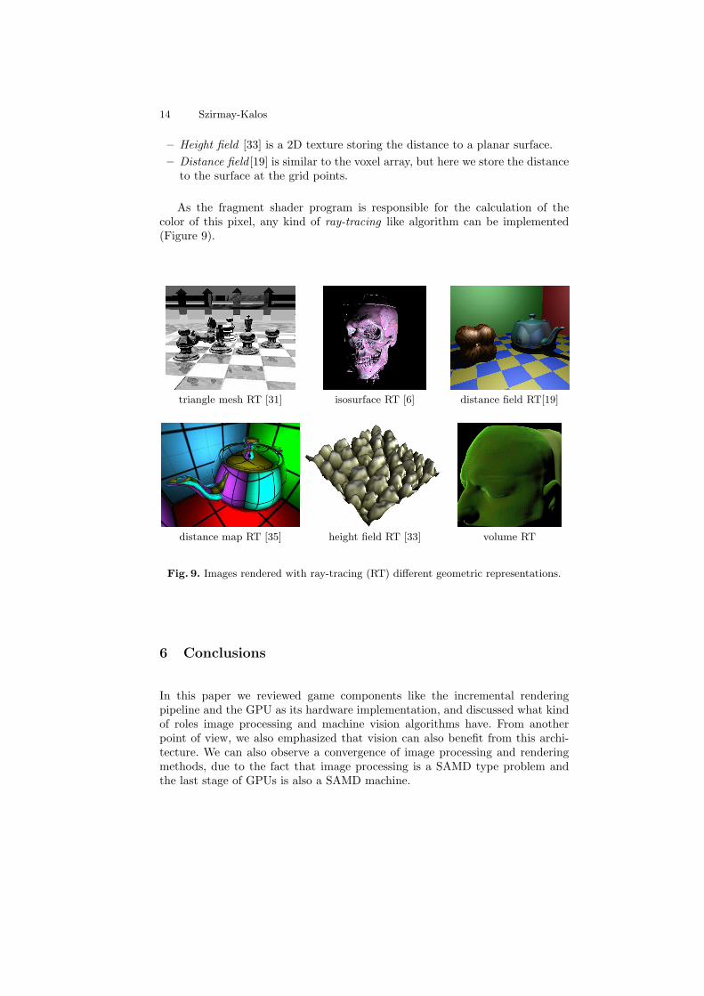
As the fragment shader program is responsible for the calculation of thecolor of this pixel, any kind of ray-tracing like algorithm can be implemented(Figure 9).
triangle mesh RT [31] isosurface RT [6] distance field RT[19]
distance map RT [35] height field RT [33] volume RT
Fig. 9. Images rendered with ray-tracing (RT) different geometric representations.
6 Conclusions
In this paper we reviewed game components like the incremental renderingpipeline and the GPU as its hardware implementation, and discussed what kindof roles image processing and machine vision algorithms have. From anotherpoint of view, we also emphasized that vision can also benefit from this archi-tecture. We can also observe a convergence of image processing and renderingmethods, due to the fact that image processing is a SAMD type problem andthe last stage of GPUs is also a SAMD machine.
Machine Vision Methods in Computer Games 15
References
1. T. Sziranyi A. Licsar. User-adaptive hand gesture recognition system with inter-active training. Image and Vision Computing, 23(12):1102–1114, 2005.
2. Gy. Antal and L. Szirmay-Kalos. Fast evaluation of subdivision surfaces on Di-rect3D 10 graphics hardware. In Wolfgang Engel, editor, ShaderX 6: AdvancedRendering Techniques, pages 5–16. Charles River Media, 2008.
3. William Baxter and Ken ichi Anjyo. Latent doodle space. Computer GraphicsForum, 25(3):477–485, 2006.
4. N. Carr, J. Hoberock, K. Crane, and J. Hart. Fast GPU ray tracing of dynamicmeshes using geometry images. In Graphics Interface 2006, pages 203–209, 2006.
5. Balazs Csebfalvi and Eduard Groller. Interactive volume rendering based on a”bubble model”. In Graphics interface 2001, pages 209–216, 2001.
6. B. Domonkos, A. Egri, T. Foris, T. Juhasz, and L. Szirmay-Kalos. Isosurfaceray-casting for autostereoscopic displays. In Proceedings of WSCG, pages 31–38,2007.
7. Funge. Artificial Intelligence for Computer Games: An Introduction. A K Peters,2004.
8. I. Garcia, M. Sbert, and L. Szirmay-Kalos. Leaf cluster impostors for tree renderingwith parallax. In Eurographics Conference. Short papers., 2005.
9. D. M. Gavrila. The visual analysis of human movement: a survey. Comput. Vis.Image Underst., 73(1):82–98, 1999.
10. Micheal Gleicher. Comparing constraint-based motion editing methods. Graph.Models, 63(2):107–134, 2001.
11. S. Gortler, R. Grzeszczuk, R. Szeliski, and M. Cohen. The lumigraph. In SIG-GRAPH 96, pages 43–56, 1996.
12. Xianfeng Gu, Steven J. Gortler, and Hugues Hoppe. Geometry images. In SIG-GRAPH ’02: Proceedings of the 29th annual conference on Computer graphics andinteractive techniques, pages 355–361, 2002.
13. M. Hadwiger, C. Sigg, H. Scharsach, K. Buhler, and M. Gross. Real-time ray-casting and advanced shading of discrete isosurfaces. Computer Graphics Forum(Eurographics ’05), 22(3):303–312, 2005.
14. Perttu Hamalainen, Tommi Ilmonen, Johanna Hoysniemi, Mikko Lindholm, andAri Nykanen. Martial arts in artificial reality. In CHI ’05: Proceedings of theSIGCHI conference on Human factors in computing systems, pages 781–790, NewYork, NY, USA, 2005. ACM.
15. Zsolt Janko, Dmitry Chetverikov, and Aniko Ekart. Using genetic algorithmsin computer vision: Registering images to 3D surface model. Acta Cybernetica,18(2):193–212, 2007.
16. Vivek Kwatra and Li-Yi Wei. Example-based texture synthesis. In SIGGRAPH’07Course notes, 2007. http://www.cs.unc.edu/˜kwatra/SIG07 TextureSynthesis/.
17. Jehee Lee, Jinxiang Chai, Paul S. A. Reitsma, Jessica K. Hodgins, and Nancy S.Pollard. Interactive control of avatars animated with human motion data. ACMTrans. Graph., 21(3):491–500, 2002.
18. M. Levoy and P. Hanrahan. Light field rendering. In SIGGRAPH 96, pages 31–42,1996.
19. Gabor Liktor. Ray tracing implicit surfaces on the GPU. In Central EuropeanSeminar on Computer Graphics, CESCG ’08, 2008.
20. Milan Magdics. Formal grammar based geometry synthesis on the GPU using thegeometry shader. In KEPAF: 7th Conference of the Hungarian Association forImage Processing and Pattern Recognition, 2009.

16 Szirmay-Kalos
21. Antoine McNamara, Adrien Treuille, Zoran Popovic, and Jos Stam. Fluid controlusing the adjoint method. In SIGGRAPH ’04, pages 449–456, 2004.
22. Paul Merrell. Example-based model synthesis. In I3D ’07: Proceedings of the 2007symposium on Interactive 3D graphics and games, pages 105–112, New York, NY,USA, 2007. ACM.
23. Greg Mori and Jitendra Malik. Estimating human body configurations using shapecontext matching. In ECCV ’02: Proceedings of the 7th European Conference onComputer Vision-Part III, pages 666–680, London, UK, 2002. Springer-Verlag.
24. Pascal Muller, Gang Zeng, Peter Wonka, and Luc Van Gool. Image-based proce-dural modeling of facades. ACM Trans. Graph., 26(3):85, 2007.
25. Zoltan Prohaszka and Andor Kerti. Development of the GPU based gpCV++image processing library. In IV. Magyar Szamıtogepes Grafika es Geometria Kon-ferencia, pages 102–107, 2007.
26. E. Reinhard, G. Ward, S. Pattanaik, and P. Debevec. High Dynamic Range Imag-ing. Morgan Kaufmann, 2006.
27. Liu Ren, Gregory Shakhnarovich, Jessica Hodgins, Hanspeter Pfister, and PaulViola. Learning silhouette features for control of human motion. ACM Transactionson Graphics, 24(4):1303–1331, 2005.
28. Romer Rosales, Matheen Siddiqui, Jonathan Alon, and Stan Sclaroff. Estimating3D body pose using uncalibrated cameras. Technical report, Boston, MA, USA,2001.
29. Takaaki Shiratori and Jessica K. Hodgins. Accelerometer-based user interfaces forthe control of a physically simulated character. In SIGGRAPH Asia ’08: ACMSIGGRAPH Asia 2008 papers, pages 1–9, 2008.
30. Laszlo Szecsi. Alias-free hard shadows with geometry maps. In Wolfgang Engel,editor, ShaderX5: Advanced Rendering Techniques, pages 219–237. Charles RiverMedia, 2007.
31. Laszlo Szecsi and Kristof Ralovich. Loose kd-trees on the GPU. In IV. MagyarSzamıtogepes Grafika es Geometria Konferencia, pages 94–101, 2007.
32. L. Szirmay-Kalos, L. Szecsi, and M. Sbert. GPU-Based Techniques for GlobalIllumination Effects. Morgan and Claypool Publishers, San Rafael, USA, 2008.
33. L. Szirmay-Kalos and T. Umenhoffer. Displacement mapping on the GPU - Stateof the Art. Computer Graphics Forum, 27(1), 2008.
34. I. Szita and A. Lorincz. Learning to play using low-complexity rule-based policies:Illustrations through Ms. Pac-Man. Image and Vision Computing, 30:659–684,2007.
35. T. Umenhoffer, G. Patow, and L. Szirmay-Kalos. Robust multiple specular reflec-tions and refractions. In Hubert Nguyen, editor, GPU Gems 3, pages 387–407.Addison-Wesley, 2007.
36. T. Umenhoffer, L. Szirmay-Kalos, and G. Szijarto. Spherical billboards and theirapplication to rendering explosions. In Graphics Interface, pages 57–64, 2006.
37. T. Varady, R. Martin, and J. Cox. Reverse engineering of geometric models - anintroduction. Computer-Aided Design, 29(4):255–268, 1997.
38. Daniel Vlasic, Ilya Baran, Wojciech Matusik, and Jovan Popovic. Articulated meshanimation from multi-view silhouettes. ACM Trans. Graph., 27(3):1–9, 2008.
39. Chuang Y., Goldman D., Zheng K., Curless B., Salesin D., and Seliski R. Animat-ing pictures with stochastic motion textures. In SIGGRAPH’05, pages 853–860,2005.
40. Kertesz Zsolt and Lovanyi Istvan. 3D motion capture methods for pathological andnon-pathological human motion analysis. In 2nd Information and CommunicationTechnologies, 2006. ICTTA ’06., pages 1062–1067, 2006.