ma24xxa/b/d and ma2400xa power sensors operation … the latest service and sales info rmation in...
TRANSCRIPT

Operation Manual
Power SensorsMA24xxA/B/D and MA2400xA
Anritsu Company490 Jarvis DriveMorgan Hill, CA 95037-2809USA
Part Number: 10585-00004Revision: T
Published: April 2011Copyright 2011 Anritsu Company
Advanced Test Equipment Rentalswww.atecorp.com 800-404-ATEC (2832)
®
Established 1981

FM-2 PN: 10585-00004 Rev. T MA24xxA/B/D, MA2400xA OM
WARRANTYThe Anritsu product(s) listed on the title page is (are) warranted against defects inmaterials and workmanship for one (1) year from the date of shipment.Anritsu’s obligation covers repairing or replacing products which prove to be defectiveduring the warranty period. Buyers shall prepay transportation charges for equipmentreturned to Anritsu for warranty repairs. Obligation is limited to the original purchaser.Anritsu is not liable for consequential damages.
LIMITATION OF WARRANTYThe foregoing warranty does not apply to Anritsu connectors that have failed due tonormal wear. Also, the warranty does not apply to defects resulting from improper orinadequate maintenance by the Buyer, unauthorized modification or misuse, or operationoutside of the environmental specifications of the product. No other warranty isexpressed or implied, and the remedies provided herein are the Buyer’s sole and exclusiveremedies.
DISCLAIMER OF WARRANTY DISCLAIMER OF WARRANTIES. TO THE MAXXIMUM EXTENT PERMITTED BYAPPLICABLE LAW, ANRITSU COMPANY AND ITS SUPPLIERS DISCLAIM ALLWARRANTIES, EITHER EXPRESS OR IMPLIED, INCLUDING, BUT NOT LIMITEDTO, IMPLIED WARRANTIES OF MERCHANTABILITY AND FITNESS FOR APARTICULAR PURPOSE, WITH REGARD TO THE SOFTWARE PRODUCT. THEUSER ASSUMES THE ENTIRE RISK OF USING THE PROGRAM. ANY LIABILITYOF PROVIDER OR MANUFACTURER WILL BE LIMITED EXCLUSIVELY TOPRODUCT REPLACEMENT.NO LIABILITY FOR CONSEQUENTIAL DAMAGES. TO THE MAXIMUM EXTENTPERMITTED BY APPLICABLE LAW, IN NO EVENT SHALL ANRITSU COMPANY ORITS SUPPLIERS BE LIABLE FOR ANY SPECIAL, INCIDENTAL, INDIRECT, ORCONSEQUENTIAL DAMAGES WHATSOEVER (INCLUDING, WITHOUTLIMITATION, DAMAGES FOR LOSS OF BUSINESS PROFITS, BUSINESSINTERRUPTION, LOSS OF BUSINESS INFORMATION, OR ANY OTHERPECUNIARY LOSS) ARISING OUT OF THE USE OF OR INABILITY TO USE THESOFTWARE PRODUCTS, EVEN IF ANRITSU COMPANY HAS BEEN ADVISED OFTHE POSSIBILITY OF SUCH DAMAGES. BECAUSE SOME STATES ANDJURISDICTIONS DO NOT ALLOW THE EXCLUSION OR LIMITATION OFLIABILITY FOR CONSEQUENTIAL OR INCIDENTAL DAMAGES, THE ABOVELIMITATION MAY NOT APPLY TO YOU.
TRADEMARK ACKNOWLEDGMENTSAnritsu is a trademark of Anritsu Company V Connector and K Connector are registered trademarks of Anritsu Company.Acrobat Reader is a registered trademark of Adobe Corporation.
NOTICEAnritsu Company has prepared this manual for use by Anritsu Company personnel andcustomers as a guide for the proper installation, operation and maintenance of AnritsuCompany equipment and computer programs. The drawings, specifications, andinformation contained herein are the property of Anritsu Company, and anyunauthorized use or disclosure of these drawings, specifications, and information isprohibited; they shall not be reproduced, copied, or used in whole or in part as the basisfor manufacture or sale of the equipment or software programs without the prior writtenconsent of Anritsu Company.
UPDATESUpdates, if any, can be downloaded from the Documents area of the Anritsu web site at:http://www.anritsu.com
For the latest service and sales information in your area, please visit:http://www.anritsu.com/contact.asp

MA24xxA/B/D, MA2400xA OM PN: 10585-00004 Rev. T FM-3
CE COMPLIANCE
Product Name: Power Sensor
Model Number:
These products were shown to be compliant, with the requirements of the following directive, when connected and used with Anritsu Power Meters.
Electromagnetic Interference: EN61326:2006
DECLARATION OF CONFORMITY
EN55011: 2007 Group 1 Class A
MA2421A, MA2421D, MA2422A, MA2422B,MA2422D, MA2468A, MA2468B, MA2468D,MA2481A, MA2481B, MA2481D, MA2469B,MA2469C, MA2469D, MA2472A, MA2472B,MA2472D, MA2482A, MA2482D, MA2442A,MA2442B, MA2442D, MA2490A, MA2491A,MA2423A, MA2423B, MA2423D, MA2473A,MA2473D, MA2424A, MA2424B, MA2424D,MA2474A, MA2474D, MA2444A, MA2444D,MA2411A, MA2411B, MA2425A, MA2425B,MA2425D, MA2475A, MA2475D, MA2445A,MA2445D, MA24002A, MA24004A, MA24005A
EMC Directive 2004/108/EC
EN 61000-4-2:1995 +A1:1998 +A2:2001 4 kV CD, 8 kV ADEN 61000-4-3:2006 +A1:2008 3V/mEN 61000-4-6:2007 3V
ML24xxA/B Series Power Meter
ML24xxA/BPower Meter
Operator Manual: Product Name: Model Number:
Emissions:
Immunity:
Reference:

FM-4 PN: 10585-00004 Rev. T MA24xxA/B/D, MA2400xA OM
Notes On Export Management
This product and its manuals may require an Export License or approval by the government of the product country of origin for re-export from your country.
Before you export this product or any of its manuals, please contact Anritsu Company to confirm whether or not these items are export-controlled.
When disposing of export-controlled items, the products and manuals need to be broken or shredded to such a degree that they cannot be unlawfully used for military purposes.
CE Conformity Marking
Anritsu affixes the CE Conformity marking onto its conforming products in accordance with Council Directives of The Council Of The European Communities in order to indicate that these products conform to the EMC and LVD directive of the European Union (EU).
Anritsu affixes the C-tick marking onto its conforming products in accordance with the electromagnetic compliance regulations of Australia and New Zealand in order to indicate that these products conform to the EMC regulations of Australia and New Zealand.

MA24xxA/B/D, MA2400xA OM PN: 10585-00004 Rev. T FM-5
European Parliament and Council Directive 2002/96/EC
Chinese RoHS Compliance Statement

FM-6 PN: 10585-00004 Rev. T MA24xxA/B/D, MA2400xA OM

MA24xxA/B/D, MA2400xA OM PN: 10585-00004 Rev. T Safety-1
Safety Symbols
To prevent the risk of personal injury or loss related to equipment malfunction, Anritsu Company uses the following symbols to indicate safety-related information. For your own safety, please read the information carefully before operating the equipment.
Symbols Used in Manuals
Danger
This indicates a very dangerous procedure that could result in serious injury or death, or loss related to equipment malfunction, if not performed properly.
WarningThis indicates a hazardous procedure that could result in light-to-severe injury or loss related to equipment malfunction, if proper precautions are not taken.
Caution
This indicates a hazardous procedure that could result in loss related to equipment malfunction if proper precautions are not taken.

Safety-2 PN: 10585-00004 Rev. T MA24xxA/B/D, MA2400xA OM
Safety Symbols Used on Equipment and in Manuals
The following safety symbols are used inside or on the equipment near operation locations to provide information about safety items and operation precautions. Ensure that you clearly understand the meanings of the symbols and take the necessary precautions before operating the equipment. Some or all of the following five symbols may or may not be used on all Anritsu equipment. In addition, there may be other labels attached to products that are not shown in the diagrams in this manual.
This indicates a prohibited operation. The prohibited operation is indicated symbolically in or near the barred circle.
This indicates a compulsory safety precaution. The required operation is indicated symbolically in or near the circle.
This indicates a warning or caution. The contents are indicated symbolically in or near the triangle.
This indicates a note. The contents are described in the box.
These indicate that the marked part should be recycled.

MA24xxA/B/D, MA2400xA OM PN: 10585-00004 Rev. T Safety-3
For Safety
Warning Always refer to the operation manual when working near locations at which the alert mark, shown on the left, is attached. If the operation, etc., is performed without heeding the advice in the operation manual, there is a risk of personal injury. In addition, the equipment performance may be reduced. Moreover, this alert mark is sometimes used with other marks and descriptions indicating other dangers.
WarningWhen supplying power to this equipment, connect the accessory 3-pin power cord to a 3-pin grounded power outlet. If a grounded 3-pin outlet is not available, use a conversion adapter and ground the green wire, or connect the frame ground on the rear panel of the equipment to ground. If power is supplied without grounding the equipment, there is a risk of receiving a severe or fatal electric shock.
Warning
This equipment can not be repaired by the operator. Do not attempt to remove the equipment covers or to disassemble internal components. Only qualified service technicians with a knowledge of electrical fire and shock hazards should service this equipment. There are high-voltage parts in this equipment presenting a risk of severe injury or fatal electric shock to untrained personnel. In addition, there is a risk of damage to precision components.
Safety-4 PN: 10585-00004 Rev. T MA24xxA/B/D, MA2400xA OM
Caution
Electrostatic Discharge (ESD) can damage the highly sensitive circuits in the instrument. ESD is most likely to occur as test devices are being connected to, or disconnected from, the instrument’s front and rear panel ports and connectors. You can protect the instrument and test devices by wearing a static-discharge wristband. Alternatively, you can ground yourself to discharge any static charge by touching the outer chassis of the grounded instrument before touching the instrument’s front and rear panel ports and connectors. Avoid touching the test port center conductors unless you are properly grounded and have eliminated the possibility of static discharge.
Repair of damage that is found to be caused by electrostatic discharge is not covered under warranty.

MA24xxA/B/D, MA2400xA OM PN: 10585-00004 Rev. T Contents-1
Table of Contents
Chapter 1—General Information
1-1 Introduction . . . . . . . . . . . . . . . . . . . . . . . . . . . . . . . . . 1-1
1-2 Power Sensor Models . . . . . . . . . . . . . . . . . . . . . . . . . 1-2
1-3 Documentation Conventions . . . . . . . . . . . . . . . . . . . . 1-3
Instrument Identification. . . . . . . . . . . . . . . . . . . . . 1-3
Hard Keys or Front Panel Keys . . . . . . . . . . . . . . . 1-3
User Interface, Menus, and Soft Buttons . . . . . . . . 1-3
User Interface Navigation Conventions . . . . . . . . . 1-3
1-4 Identification Numbers . . . . . . . . . . . . . . . . . . . . . . . . 1-4
1-5 Online Manual . . . . . . . . . . . . . . . . . . . . . . . . . . . . . . . 1-4
1-6 Test Equipment List . . . . . . . . . . . . . . . . . . . . . . . . . . 1-4
1-7 Sensor Handling Requirements . . . . . . . . . . . . . . . . . 1-5
1-8 Sensor Repair and Calibration . . . . . . . . . . . . . . . . . . 1-5
1-9 ESD Requirements . . . . . . . . . . . . . . . . . . . . . . . . . . . 1-6
1-10 Service Policy . . . . . . . . . . . . . . . . . . . . . . . . . . . . . . . 1-6
Unit Exchange Policy . . . . . . . . . . . . . . . . . . . . . . . 1-6
1-11 Anritsu Sales and Service . . . . . . . . . . . . . . . . . . . . . . 1-6
Chapter 2—Functional Description
2-1 Introduction . . . . . . . . . . . . . . . . . . . . . . . . . . . . . . . . . 2-1
Sensor Function. . . . . . . . . . . . . . . . . . . . . . . . . . . 2-1
Power Sensing Elements. . . . . . . . . . . . . . . . . . . . 2-1
Power Sensor Problem Solving . . . . . . . . . . . . . . . 2-1

Contents-2 PN: 10585-00004 Rev. T MA24xxA/B/D, MA2400xA OM
Table of Contents (Continued)
2-2 Sensor Descriptions . . . . . . . . . . . . . . . . . . . . . . . . . . . 2-2
MA247xD Standard Diode Sensors . . . . . . . . . . . . 2-2
MA244xD High Accuracy Diode Sensors . . . . . . . . 2-3
MA248xD Universal Sensors . . . . . . . . . . . . . . . . . 2-3
MA249xA Wideband Sensors . . . . . . . . . . . . . . . . . 2-4
MA2411B Pulse Sensors . . . . . . . . . . . . . . . . . . . . 2-4
MA2400xA Thermal Sensors . . . . . . . . . . . . . . . . . 2-5
MA246xD Fast Diode Sensors (obsolete) . . . . . . . . 2-5
Chapter 3—Power Sensor Care
3-1 Introduction. . . . . . . . . . . . . . . . . . . . . . . . . . . . . . . . . . 3-1
3-2 Power Sensor Precautions. . . . . . . . . . . . . . . . . . . . . . 3-2
3-3 RF Connector Precautions . . . . . . . . . . . . . . . . . . . . . . 3-3
3-4 Connection Techniques . . . . . . . . . . . . . . . . . . . . . . . . 3-4
Connection Procedure. . . . . . . . . . . . . . . . . . . . . . . 3-4
Disconnection Procedure . . . . . . . . . . . . . . . . . . . . 3-5
3-5 RF Connector Care . . . . . . . . . . . . . . . . . . . . . . . . . . . 3-5
Visual Inspection . . . . . . . . . . . . . . . . . . . . . . . . . . . 3-5
Pin Depth Measurement . . . . . . . . . . . . . . . . . . . . . 3-6
Pin Depth Dimensions. . . . . . . . . . . . . . . . . . . . . . . 3-8
Pin Depth Gauge. . . . . . . . . . . . . . . . . . . . . . . . . . . 3-8
Pin Depth Tolerances . . . . . . . . . . . . . . . . . . . . . . . 3-9
3-6 Connector Cleaning . . . . . . . . . . . . . . . . . . . . . . . . . . 3-10
Required Cleaning Items. . . . . . . . . . . . . . . . . . . . 3-11
Important Cleaning Tips . . . . . . . . . . . . . . . . . . . . 3-11
Cleaning Procedure. . . . . . . . . . . . . . . . . . . . . . . . 3-11
Chapter 4—Performance Verification
4-1 Introduction. . . . . . . . . . . . . . . . . . . . . . . . . . . . . . . . . . 4-1
4-2 General Information . . . . . . . . . . . . . . . . . . . . . . . . . . . 4-1
4-3 SWR Performance . . . . . . . . . . . . . . . . . . . . . . . . . . . . 4-2
Required Equipment . . . . . . . . . . . . . . . . . . . . . . . . 4-2
Measurement . . . . . . . . . . . . . . . . . . . . . . . . . . . . . 4-3

MA24xxA/B/D, MA2400xA OM PN: 10585-00004 Rev. T Contents-3
Table of Contents (Continued)
4-4 Sensitivity Performance . . . . . . . . . . . . . . . . . . . . . . . 4-4
Required Equipment . . . . . . . . . . . . . . . . . . . . . . . 4-4
Setup: ML24xx Power Meter . . . . . . . . . . . . . . . . . 4-4
Setup: ML248xx Power Meter . . . . . . . . . . . . . . . . 4-5
Procedure: Standard Power Sensors . . . . . . . . . . 4-5
Procedure: Universal Power Sensors . . . . . . . . . . 4-6
Return Meter to Power Measurement Mode . . . . . 4-8
4-5 Measurement Uncertainty . . . . . . . . . . . . . . . . . . . . . . 4-8
General Information . . . . . . . . . . . . . . . . . . . . . . . . 4-8
Uncertainty Examples . . . . . . . . . . . . . . . . . . . . . . 4-9
4-6 Cal Factor Uncertainty . . . . . . . . . . . . . . . . . . . . . . . 4-11
Calibration Factor Uncertainty Tables . . . . . . . . . 4-11
Appendix A—Test Records
A-1 Introduction . . . . . . . . . . . . . . . . . . . . . . . . . . . . . . . . . A-1
A-2 Measurement Uncertainty . . . . . . . . . . . . . . . . . . . . . . A-1
A-3 Test Records. . . . . . . . . . . . . . . . . . . . . . . . . . . . . . . . A-1
A-4 SWR Performance Data . . . . . . . . . . . . . . . . . . . . . . . A-2
MA247xA . . . . . . . . . . . . . . . . . . . . . . . . . . . . . . . . A-2
MA2472B/D . . . . . . . . . . . . . . . . . . . . . . . . . . . . . . A-3
MA2400xA . . . . . . . . . . . . . . . . . . . . . . . . . . . . . . . A-4
MA244xx (Except MA2442B/D) . . . . . . . . . . . . . . . A-5
MA2442B/D . . . . . . . . . . . . . . . . . . . . . . . . . . . . . . A-6
MA2481A . . . . . . . . . . . . . . . . . . . . . . . . . . . . . . . . A-7
MA2481B/D, MA2482A/D . . . . . . . . . . . . . . . . . . . A-8
MA249xA . . . . . . . . . . . . . . . . . . . . . . . . . . . . . . . . A-9
MA2411x . . . . . . . . . . . . . . . . . . . . . . . . . . . . . . . A-10
MA2421A/D (obsolete). . . . . . . . . . . . . . . . . . . . . A-11
MA2468A, MA2469A, MA2469B (obsolete). . . . . A-12
MA2468B/D, MA2469C/D (obsolete) . . . . . . . . . . A-13
A-5 Sensitivity Performance Data . . . . . . . . . . . . . . . . . . A-14
Sensor Sensitivity Performance. . . . . . . . . . . . . . A-14
Appendix B—Specifications
B-1 Technical Data Sheet . . . . . . . . . . . . . . . . . . . . . . . . . B-1

Contents-4 PN: 10585-00004 Rev. T MA24xxA/B/D, MA2400xA OM
Table of Contents (Continued)
B-2 Performance Specifications . . . . . . . . . . . . . . . . . . . . .B-1
Standard Diode Power Sensors . . . . . . . . . . . . . . .B-2
Thermal Sensors . . . . . . . . . . . . . . . . . . . . . . . . . . .B-4
High Accuracy Sensors . . . . . . . . . . . . . . . . . . . . . .B-6
Universal Power Sensors . . . . . . . . . . . . . . . . . . . .B-8
Pulse Power Sensor . . . . . . . . . . . . . . . . . . . . . . . .B-9
Wide Bandwidth Power Sensors . . . . . . . . . . . . .B-10
Thermal Sensors (Obsolete) . . . . . . . . . . . . . . . .B-11
CDMA Power Sensors (Obsolete) . . . . . . . . . . . .B-13
Subject Index

MA24xxA/B/D, MA2400xA OM PN: 10585-00004 Rev. T 1-1
Chapter 1 — General Information
1-1 Introduction This manual provides descriptions and specifications for Anritsu Power Sensors that are used in conjunction with Anritsu power meters. It includes care, handling and performance verification information.
Anritsu offers the world's most comprehensive range of power meters:
• The ML2490 series has the performance required for narrow fast rising-edge pulse power measurements (e.g., radar).
• The ML2480 series is suited for wideband power measurements on signals such as W-CDMA, WLAN, and WiMAX.
• The ML2430 series is designed for CW applications, offering a combination of accuracy, speed and flexibility in a low cost package.
With various families of Power Sensors to choose from, you can trust you'll find the right combination for precision power measurement. Anritsu Power Sensors include:
• MA247xD Series Standard Diode Power Sensors
• MA244xD Series High Accuracy Power Sensors
• MA248xD Series Universal Power Sensors
• MA249xA Series Wideband Power Sensors
• MA2411B Pulse Power Sensor.
• MA2400xA Thermal Sensors
All Anritsu power sensors contain an internal EEPROM for storage of calibration data as a function of frequency, power, and temperature. This allows the power meter to interpolate and correct readings automatically.
Note
Anritsu ML2407A/08A and ML2437A/38A Power Meters must have meter firmware revision 3.10 or higher when used with Anritsu MA24xxD and MA2400xA Series power sensors.
Note USB sensors are not covered in this manual.

1-2 PN: 10585-00004 Rev. T MA24xxA/B/D, MA2400xA OM
1-2 Power Sensor Models Chapter 1 — General Information
1-2 Power Sensor ModelsListed in Table 1-1 are the currently available models covered in this manual. Full specifications for each are in Appendix B.
Table 1-1. Power Sensor Models
Type/Model Frequency Range Power Range
Standard Diode Sensors
MA2472D 10 MHz to 18 GHz –70 dBm to 20 dBm
MA2473D 10 MHz to 32 GHz –70 dBm to 20 dBm
MA2474D 10 MHz to 40 GHz –70 dBm to 20 dBm
MA2475D 10 MHz to 50 GHz –70 dBm to 20 dBm
High Accuracy Diode Sensors
MA2442D 10 MHz to 18 GHz –67 dBm to 20 dBm
MA2444D 10 MHz to 40 GHz –67 dBm to 20 dBm
MA2445D 10 MHz to 50 GHz –67 dBm to 20 dBm
Universal Sensors
MA2481D 10 MHz to 6 GHz –60 dBm to 20 dBm
MA2482D 10 MHz to 18 GHz –60 dBm to 20 dBm
Wideband Sensors
MA2490A 50 MHz to 8 GHz –60 dBm to 20 dBm
MA2491A 50 MHz to 18 GHz –60 dBm to 20 dBm
Pulse Sensor
MA2411B 300 MHz to 40 GHz –20 dBm to 20 dBm
Thermal Sensors
MA24002A 10 MHz to 18 GHz –30 dBm to 20 dBm
MA24004A 10 MHz to 40 GHz –30 dBm to 20 dBm
MA24005A 10 MHz to 50 GHz –30 dBm to 20 dBm

MA24xxA/B/D, MA2400xA OM PN: 10585-00004 Rev. T 1-3
Chapter 1 — General Information 1-3 Documentation Conventions
1-3 Documentation ConventionsThe following conventions are used throughout this document:
Instrument Identification
Throughout this manual, the terms MA24xxA/B/D and MA2400xA, Power Sensor, or DUT (device under test) are used to refer to the power sensor. When required to identify a specific model, the specific model number is used, such as MA2496A. Manual organization is shown in the table of contents.
Hard Keys or Front Panel Keys
When testing sensors, the power meter and test equipment front panel hard keys are denoted with a bold Sans Serif font such as “Press the front panel Frequency key.”
User Interface, Menus, and Soft Buttons
The power meter user interface consists of menus, button lists, sub-menus, toolbars, and dialog boxes. All of these elements are denoted with a special font, such as the Calibration menu or the AutoCal button.
User Interface Navigation Conventions
Navigation in Power Meter and Test Equipment
Elements in navigation shortcuts or paths (identified as “Navigation”) are separated with the pipe symbol (“|”). Menu and dialog box names are distinctive Sans Serif font. Button names are in Title Case. For example, you would enter the power meter Service Mode by pressing the front panel keys in the following sequence:
System | Service | Diag | 0 | Enter
This string means you would: press the System hard key | press the Service soft key | press the Diag soft key | press the 0 keypad hard key | Press the Enter soft key.

1-4 PN: 10585-00004 Rev. T MA24xxA/B/D, MA2400xA OM
1-4 Identification Numbers Chapter 1 — General Information
1-4 Identification NumbersAn Anritsu model number and serial number is located on the power sensor. Please use these numbers when corresponding with Anritsu Customer Service.
1-5 Online ManualThis manual is available online at www.anritsu.com.
1-6 Test Equipment ListTable 1-2 provides a list of recommended test equipment needed for the performance verification procedures presented in this manual. The test equipment setup is critical to making accurate measurements. In some cases, you may substitute test equipment having the same critical specifications as the test equipment indicated in the test equipment list (refer to“Measurement Uncertainty” on page 4-8 and “Cal Factor Uncertainty” on page 4-11).
Table 1-2. Test Equipment List (1 of 2)
Instrument Critical SpecificationManufacturer
and ModelUsage
(a)
Vector Network Analyzer
Measurement uncertainty equal to or lower than that given in the tables of Section A-4 of Appendix A
Anritsu 37000 Vector Network Analyzer
P, T
Scalar Network Analyzer
Measurement uncertainty equal to or lower than that given in the tables of Section A-4 of Appendix A
Anritsu 54000 Scalar Network Analyzer
P, T
Attenuator: 20 dB
Attenuation accuracy ±0.5 dB at 2 GHz or better (required for testing the Universal power sensor)
Anritsu 41KC-20 Fixed Attenuator
P, T

MA24xxA/B/D, MA2400xA OM PN: 10585-00004 Rev. T 1-5
Chapter 1 — General Information 1-7 Sensor Handling Requirements
1-7 Sensor Handling RequirementsThe following handling precautions must be observed when using Anritsu power sensors. These are described in greater detail in Chapter 3, “Power Sensor Care”.
• Avoid over-torquing connectors
• Avoid mechanical shock
• Avoid applying excessive power
• Observe proper ESD precautions
• Keep the sensor connectors clean
1-8 Sensor Repair and CalibrationThere are no user serviceable parts inside the power sensors. Contact your local Anritsu Service Center and return the power sensor with a detailed description of the observed problem.
Various coaxial adapters
N/AAny common source
P, T
Synthesized Signal Generator
Minimum power accuracy of ±1 dB at 2 GHz for power levels from +20 dBm to –10 dBm
Anritsu 68387B Synthesized Signal Generator
P, T
Power Meter ML2480 Series Power Meter required for MA249xA and MA2411A/B Series power sensors
Anritsu ML2400 Series Power Meter P, T
a. P = Performance Verification Tests, C = Calibration, T = Troubleshooting
Table 1-2. Test Equipment List (2 of 2)
Instrument Critical SpecificationManufacturer
and ModelUsage
(a)

1-6 PN: 10585-00004 Rev. T MA24xxA/B/D, MA2400xA OM
1-9 ESD Requirements Chapter 1 — General Information
1-9 ESD RequirementsAll electronic devices, components, and instruments can be damaged by electrostatic discharge. It is important to take preventive measures to protect the instrument and its internal subassemblies from electrostatic discharge.
An ESD safe work area and proper ESD handling procedures that conform to ANSI/ESD S20.20-2007 is mandatory to avoid ESD damage when handling subassemblies or components found in Anritsu instruments.
1-10 Service Policy The power sensor service policy is to exchange the complete unit. This policy ensures minimum down time for the customer.
Unit Exchange Policy
The customer returns the power sensor to the nearest Anritsu Customer Service Center and an identical sensor is issued in exchange. The original unit is repaired, calibrated and returned to the customer, whereupon the customer returns the exchange unit to the Anritsu Customer Service Center. The original sensor is returned with the same identification marks and serial number as it had before the repair.
1-11 Anritsu Sales and Service To locate the nearest Anritsu Customer Service or Sales Center, please refer to the Anritsu web page:
http://www.anritsu.com

MA24xxA/B/D, MA2400xA OM PN: 10585-00004 Rev. T 2-1
Chapter 2 — Functional Description
2-1 IntroductionAnritsu sensors are classified into three general types:
• MA2400xA Thermal Sensors
• MA247xx, MA244xx, MA249xx, and MA2411x Diode Sensors
• MA248xx Universal Sensors
Sensor Function
All the above sensors have one common function:
For a given signal frequency, they translate a sensed input power into an output voltage. The Anritsu ML2400 Series power meters interpret the sensor voltages with signal frequencies and output correct power readings.
Power Sensing Elements
Both diode sensors and thermal sensors have a single power sensing element. Therefore, they have only one voltage versus power relationship. Universal sensors have three power sensing elements, and they have three sets of voltage versus power relationships.
Power Sensor Problem Solving
The most common cause of power sensor problems is excess input power. Applying power exceeding the labeled damage levels will damage the sensing element(s) such that its voltage versus power relationships are changed, resulting in erroneous power readings.
The other most common cause of power sensor problems is damaged connectors. Connections should be tightened with the proper torque wrench applied to the coupling nut only. Any attempt to torque or untorque a connection using the body of the power sensor may result in either connector damage, or in the connector becoming unthreaded from the body.

2-2 PN: 10585-00004 Rev. T MA24xxA/B/D, MA2400xA OM
2-2 Sensor Descriptions Chapter 2 — Functional Description
Since the connector-to-body threads have thread-locking compound applied, slight unthreading of the connector from the body may not be physically apparent. Unthreaded or damaged connectors will change the voltage versus power relationships. These changes are usually manifested as a poor input match.
Any suspect power sensor should have two parameters tested:
• SWR (reflection coefficient magnitude)
• Sensitivity
Refer to Chapter 4 for test instructions.
2-2 Sensor Descriptions
MA247xD Standard Diode Sensors
Description
The Anritsu MA247xD standard diode sensors are designed for use with the ML2430, ML2480 and ML2490 series power meters. They are designed for high dynamic range, high accuracy CW and TDMA measurements. These power sensors have 90 dB dynamic range and linearity better than 1.8% making them the choice for precision measurements. The 4 s rise time of these sensors is fast enough for power measurements on GSM and similar TDMA systems that use GMSK modulation.
Features
• Wide dynamic range sensors (–70 dBm to +20 dBm)
• Accurate CW average power measurements
• Wide frequency coverage from 10 MHz to 50 GHz (sensor dependent)
• Calibration factors stored in EEPROM
Note
There are no user serviceable parts inside the power sensors. Contact your local Anritsu Service Center and return the power sensor with a detailed description of the observed problems.

MA24xxA/B/D, MA2400xA OM PN: 10585-00004 Rev. T 2-3
Chapter 2 — Functional Description 2-2 Sensor Descriptions
MA244xD High Accuracy Diode Sensors
Description
The Anritsu MA244xD standard diode sensors are designed for use with the ML2430, ML2480 and ML2490 series power meters. They are designed for high dynamic range, high accuracy CW and TDMA measurements. With a built-in 3 dB attenuator, the MA244xD minimizes input SWR and is best used where the best measurement accuracy is required over a large dynamic range, as when measuring amplifiers. The MA244xD sensors have a dynamic range of 87 dB compared to the 90 dB dynamic range of MA247xD standard diode sensors.
Features
• Wide dynamic range sensors (-67 dBm to +20 dBm)
• Accurate CW average power measurements
• Wide frequency coverage from 10 MHz to 50 GHz (sensor dependent)
• Calibration factors stored in EEPROM
MA248xD Universal Sensors
Description
The MA248xD series are true RMS sensors with a dynamic range of 80 dB. These power sensors can be used for average power measurements on CW, multi-tone and modulated RF waveforms such as 3G, 4G, and OFDM. The sensor architecture consists of three pairs of diodes, each one configured to work in its square law region over the dynamic range of the sensor. Therefore, it measures true RMS power regardless of the type or bandwidth of the modulation of the input signal. Option 1 provides TDMA measurement capability, calibrating one of the diode pairs for linearity over a wide dynamic range, thus making it a truly universal sensor.
Features
• True-RMS detection enables accurate average power measurements of any signal type

2-4 PN: 10585-00004 Rev. T MA24xxA/B/D, MA2400xA OM
2-2 Sensor Descriptions Chapter 2 — Functional Description
• 80 dB dynamic range
• Option 1 enables fast and accurate (1.8% linearity) CW average power measurements
• Wide frequency coverage from 10 MHz to 18 GHz (sensor dependent)
• Calibration factors stored in EEPROM
MA249xA Wideband Sensors
Description
The Anritsu MA249xA wideband power sensors are designed for use with the Anritsu ML2480 and ML2490 series power meters. These sensors provide peak power, crest factor, average power, rise time, fall time, maximum power, minimum power and statistical data of wideband signals.
Features
• Ideal for measuring radar and communication signals like WiMAX, WCDMA, WLAN, GSM, and others
• CW and Average power measurements as low as –60 dBm
• 20 MHz video bandwidth
• Sampling rate of 64 MS/s with ML2480 and ML2490 series power meters
MA2411B Pulse Sensors
Description
The Anritsu MA2411B pulse power sensors are designed for use with the ML2480 and ML2490 series power meters. These sensors are used for pulse profiling and provide peak power, crest factor, average power, rise time, fall time, maximum power, minimum power and statistical data of wideband signals. The MA2411x Series Power Sensors requires the ML2480 series power meter to be equipped with 1 GHz Calibrator (Option 15).
Features
• Ideal for measuring pulsed radar and communication signals

MA24xxA/B/D, MA2400xA OM PN: 10585-00004 Rev. T 2-5
Chapter 2 — Functional Description 2-2 Sensor Descriptions
• 50 MHz video bandwidth
• Upper measurement frequency range of 40 GHz
• An industry best 8 ns rise time
MA2400xA Thermal Sensors
Description
The Anritsu MA2400xA series thermal sensors provide excellent power measurement accuracy over 50 dB of dynamic range. Thermal sensors use Seebeck elements where the combined effect of a thermal gradient and charge migration between dissimilar metals gives a true reading of the average power of any incident waveform. Anritsu thermal sensors have class leading SWR and a built-in EEPROM with calibration factor and linearity correction data. This results in assured accuracy when measuring any signal.
Features
• True-RMS detection enables accurate average power measurements of any signal type
• 50 dB dynamic range
• Wide frequency coverage from 10 MHz to 50 GHz (sensor dependent)
• Calibration factors stored in EEPROM
MA246xD Fast Diode Sensors (obsolete)
Description
The MA246xD fast diode sensors from Anritsu have a rise time of 0.6 s. This, together with a sensor video bandwidth of 1.25 MHz, makes them the ideal solution for power measurements on N-CDMA (IS-95) signals.
The MA246xD sensors can be used with the ML2407A/08A (obsolete products), ML2430, ML2480, and ML2490 series power meters. This combination of meter and sensor provides fast signal processing and sampling speeds. Average power, peak power and crest factor on N-CDMA signals can be measured and displayed.

2-6 PN: 10585-00004 Rev. T MA24xxA/B/D, MA2400xA OM
2-2 Sensor Descriptions Chapter 2 — Functional Description
The MA246xD are dual diode sensors that deliver a greater than 80 dB dynamic range, which makes them suitable for both open and closed loop power control testing. Pulses down to 1 s can also be captured and displayed, thanks to the sensor rise time of 0.6 s. In profile mode the meter can be used to measure average power across narrow pulses, an increasingly common test method for amplifiers in digitally modulated systems.
Features
• Ideal for measuring CDMA signals
• Average, peak and crest factor measurements
• 1.25 MHz video bandwidth

MA24xxA/B/D, MA2400xA OM PN: 10585-00004 Rev. T 3-1
Chapter 3 — Power Sensor Care
3-1 IntroductionAnritsu Power Sensors are high quality precision laboratory instruments and should receive the same care and respect afforded such instruments. Follow the precautions listed below when handling or connecting these devices. Complying with these precautions will guarantee longer component life and less equipment downtime due to connector or device failure. This will ensure that power sensor failures are not due to misuse or abuse – two failure modes not covered under the Anritsu warranty.
Based on RF components returned for repair, destructive pin depth of mating connectors is the major cause of failure in the field. When an RF component connector is mated with a connector having a destructive pin depth, damage will usually occur to the RF component connector. A destructive pin depth is one that is too long in respect to the reference plane of the connector (see Figure 3-1 on page 3-8).
The center pin of a precision RF component connector has a precision tolerance measured in mils (1/1000 inch). The mating connectors of various RF components may not be precision types. Consequently, the center pins of these devices may not have the proper pin depth. The pin depth of DUT connectors should be measured to assure compatibility before attempting to mate them with Power Sensor connectors. An Anritsu Pin Depth Gauge (Figure 3-2), or equivalent, can be used for this purpose.
Warning Beware of destructive pin depth of mating connectors.
WarningBeware of RF components that may not have precision type connectors.

3-2 PN: 10585-00004 Rev. T MA24xxA/B/D, MA2400xA OM
3-2 Power Sensor Precautions Chapter 3 — Power Sensor Care
3-2 Power Sensor Precautions
Avoid Over Torquing Connectors
Over torquing connectors is destructive; it may damage the connector center pin. A torque wrench (12 inch-pounds or 1.35 N· m) is recommended for tightening N connectors. Always use a torque wrench (8 inch-pounds or 0.90 N· m) for K and V type connectors. Never use pliers to tighten connectors. Refer to Section 3-4 “Connection Techniques” on page 3-4 for detailed instructions.
Avoid Mechanical Shock
Power Sensors are designed to withstand years of normal bench handling. However, do not drop or otherwise treat them roughly. Mechanical shock will significantly reduce their service life.
Avoid Applying Excessive Power
Exceeding the specified maximum input power level will permanently damage power sensor internal components and render it useless.
Observe Proper ESD Precautions
Power sensors contain components that can be destroyed by electrostatic discharges (ESD). Therefore, power sensors should be treated as ESD-sensitive devices. To prevent ESD damage, do not handle, transport or store a power sensor except in a static safe environment. A static control wrist strap MUST be worn when handling power sensors. Do not use torn or punctured static-shielding bags for storage of sensors. Do not place any paper documents such as instructions, customer orders or repair tags inside the protective packaging with the sensors.

MA24xxA/B/D, MA2400xA OM PN: 10585-00004 Rev. T 3-3
Chapter 3 — Power Sensor Care 3-3 RF Connector Precautions
Clean the Connectors
The precise geometry that makes the RF component’s high performance possible can easily be disturbed by dirt and other contamination adhering to the connector interfaces. When not in use, keep the connectors covered. Connector s must be cleaned using a lint-free cotton swab that has been dampened with isopropyl alcohol (IPA). Refer to Section 3-6 “Connector Cleaning” on page 3-10 for specific details.
3-3 RF Connector Precautions
Handle With Care
RF connectors are designed to withstand years of normal bench handling. However, do not drop or otherwise treat them roughly. They are laboratory-quality devices, and like other such devices, they require careful handling.
Keep Connectors Clean
Avoid touching connector mating planes with bare hands. Natural skin oils and microscopic dirt particles are very hard to remove.
When using cotton swabs to clean connectors, make sure that you don’t damage the center conductor. Refer to Section 3-6.
Check the Pin Depth
Always check the pin depth of a new connector before use to determine if it is out of spec. One bad connector can damage many. The connector can be damaged by turning in the wrong direction. Turning right tightens and turning left loosens.
Teflon Tuning Washers
The center conductor on most RF components contains a small teflon tuning washer located near the point of mating (interface). This washer compensates for minor impedance discontinuities at the interface. The washer’s location is critical to the RF component’s performance. Do not disturb it.

3-4 PN: 10585-00004 Rev. T MA24xxA/B/D, MA2400xA OM
3-4 Connection Techniques Chapter 3 — Power Sensor Care
Torque Properly
Over torquing connectors is destructive; it may damage the connector center pin. Never use pliers to tighten connectors. For other connectors, use the correct torque wrench.
Cover the Connectors
Put ESD-safe dust caps on the connector after use.
Store Properly
Never store adapters loose in a box, in a desk, or in a drawer.
3-4 Connection Techniques
Connection Procedure
Table 3-1 below lists the Anritsu Company torque wrench and open end wrench part numbers for different connectors.
1. Hold torque wrench at the end.
2. Rotate only the connector nut when you tighten the connector. Use an open-end wrench to keep the body of the connector from turning.
Table 3-1. Connector Wrench Requirements – Torque Wrenches and Settings – Open End Wrenches
Connector Type
Torque Wrench Model Number
TorqueSpecification
Open End Wrench
3.5 mm/SMA 01-201 8 in-lbs (0.90 N·m) 01-204
K (2.92 mm) 01-201 8 in-lbs (0.90 N·m) 01-204
V (1.85 mm) 01-201 8 in-lbs (0.90 N·m) 01-204
N 01-200 12 in-lbs (1.35 N·m) 01-202
CautionHolding the torque wrench elsewhere applies an unknown amount of torque and could damage contacts and/or connectors.

MA24xxA/B/D, MA2400xA OM PN: 10585-00004 Rev. T 3-5
Chapter 3 — Power Sensor Care 3-5 RF Connector Care
3. Using two wrenches with an angle greater than 90° causes the connector devices to lift up and tends to misalign the devices and stress the connectors. This becomes more of a problem when there are several devices connected to each other.
4. Breaking the handle fully can cause the wrench to kick back and may loosen the connection.
Disconnection Procedure
1. Use an open end wrench to prevent the connector body from turning.
2. Use another wrench to loosen the connector nut.
3. Complete the disconnection by hand, turning only the connector nut.
4. Pull the connectors straight apart without twisting or bending.
3-5 RF Connector CareMost coax connectors are assembled into a system and forgotten, but some, especially on test equipment are used almost continuously. The care and cleaning of these connectors is critical to accurate and reliable performance. Remember that all connectors have a limited life time and usually a maximum connect/disconnect specification, typically about 5,000 connections. Most will last well beyond this number, but poor usage and poor care can destroy a connector well before that number. Good connector performance can be achieved with the following:
• Periodic visual inspection
• Cleaning
• Proper connection and disconnection techniques using torque wrench
• Appropriate gauging techniques
Visual Inspection
To ensure a long and reliable connector life, careful visual inspection should be performed on the connectors before they are used on a particular job at a minimum of once per day when the item is being used. A “good” connector may get damaged if it is mated with a “bad” one.

3-6 PN: 10585-00004 Rev. T MA24xxA/B/D, MA2400xA OM
3-5 RF Connector Care Chapter 3 — Power Sensor Care
Magnification
The minimum magnification for connector inspection for damage varies with the connector:
• 7X for K (2.92 mm) and V (1.85 mm) connectors
• 2X for N connectors
• 10X for W1 (1.0 mm) connectors
Any connector with the following defects should be repaired or discarded:
Plating
• Deep scratches showing bare metal on the mating plane
• Bubbles and blisters
The connectors may lose some gloss over time due to usage. Light scratches, marks and other cosmetic imperfections can be found on the mating plane surfaces. These should be of no cause for concern.
Threads
• Damaged threads. Don’t force the connectors to mate with each other.
Center conductors
• Bent, broken or damaged contacts.
Pin Depth Measurement
Precautions
A connector should be checked before it is used at a minimum of once per day when in use. If the connector is to be used on another item of equipment, the connector on the equipment to be tested should also be gauged.
Warning Beware of destructive pin depth of mating connectors.

MA24xxA/B/D, MA2400xA OM PN: 10585-00004 Rev. T 3-7
Chapter 3 — Power Sensor Care 3-5 RF Connector Care
Connectors should never be forced together when making a connection since forcing often indicates incorrectness and incompatibility. There are some dimensions that are critical for the mechanical integrity, non-destructive mating and electrical performance of the connector. Connector gauge kits are available for many connector types. Please refer to Anritsu Application Note 10200-00040. The mechanical gauging of coaxial connectors will detect and prevent the following problems:
Positive Pin Depth
Positive pin depth can result in buckling of the fingers of the female center conductor or damage to the internal structure of a device due to the axial forces generated.
Negative Pin Depth
Negative pin depth can result in poor return loss, possibly unreliable connections, and could even cause breakdown under peak power conditions.
Checking the Pin Depth Gauge
Pin depth gauges should be checked for cleanliness before they are used at a minimum of once per month. Connector cleaning procedures (refer to Section 3-6) can also be used to clean the pin depth gauges.
CautionNever make a connection when any positive pin depth condition exists.

3-8 PN: 10585-00004 Rev. T MA24xxA/B/D, MA2400xA OM
3-5 RF Connector Care Chapter 3 — Power Sensor Care
Pin Depth Dimensions
Before mating, measure the pin depth of the device that will mate with the RF component. The dimensions to measure are shown in Figure 3-1.
Pin Depth Gauge
Use an Anritsu Pin Depth Gauge or equivalent as shown below in Figure 3-2 to accurately measure pin depths.
Based on RF components returned for repair, destructive pin depth of mating connectors is the major cause of failure in the field. When an RF component is mated with a connector having a destructive pin depth, damage will likely occur to the RF component connector.
Figure 3-1. N Connector Pin Depth
NoteA destructive pin depth has a center pin that is too long in respect to the connector’s reference plane.
ReferencePlane
ReferencePlane
Pin Depth(Inches)
Pin Depth(Inches)
MALEFEMALE

MA24xxA/B/D, MA2400xA OM PN: 10585-00004 Rev. T 3-9
Chapter 3 — Power Sensor Care 3-5 RF Connector Care
Pin Depth Tolerances
The center pin of RF component connectors has a precision tolerance measured in “mils” which is equal to 1/1000 inch (0.001”) or approximately 0.02540 mm.
V connectors have a higher precision tolerance measured in “tenths” or 1/10,000 inch (0.0001”) or approximately 0.00254 mm.
Connectors on test devices that mate with RF components may not be precision types and may not have the proper depth. They must be measured before mating to ensure suitability and to avoid connector damage.
When gauging pin depth, if the test device connector measures out of tolerance (see Table 3-2) in the “+” region of the gauge (see Figure 3-2 on page 3-9), the center pin is too long. Mating under this condition will likely damage the termination connector.
On the other hand, if the test device connector measures out of tolerance in the “–” region, the center pin is too short. While this will not cause any damage, it will result in a poor connection and a consequent degradation in performance.
Figure 3-2. Pin Depth Gauge
01
2
3
45
1
2
3
4
21 1
2
1
3 2
1 – Pin Depth Gauge with needle setting at zero.2 – Positive needle direction clockwise to right.3 – Negative needle direction counter-clockwise to left.

3-10 PN: 10585-00004 Rev. T MA24xxA/B/D, MA2400xA OM
3-6 Connector Cleaning Chapter 3 — Power Sensor Care
3-6 Connector CleaningConnector interfaces — especially the outer conductors on the GPC 7 and SMA connectors — should be kept clean and free of dirt and other debris.
Clean connectors with lint-free cotton swabs. Isopropyl alcohol is the recommended solvent. Figure 3-3 on page 3-13 illustrates the cleaning procedures for male and female connectors.
Table 3-2. Pin Depth Tolerances and Gauge Settings
Connector Type Pin Depth (Inches) Anritsu Gauge Setting
GPC-7+0.000
–0.003Same as pin depth
N Male
+0.003
–0.207
0.000
0.000
–0.207
–0.003
N Female
0.000
–0.207
–0.003
0.000
–0.207
–0.003
WSMA Male –0.0025
–0.0035Same as pin depth
WSMA Female
K Male +0.000
–0.003Same as pin depth
K Female
V Male +0.000
–0.002Same as pin depth
V Female
Note
Most cotton swabs are too large to fit into the ends of the smaller connector types. In these cases it is necessary to peel off most of the cotton and then twist the remaining cotton tight. Be sure that the remaining cotton does not get stuck in the connector.

MA24xxA/B/D, MA2400xA OM PN: 10585-00004 Rev. T 3-11
Chapter 3 — Power Sensor Care 3-6 Connector Cleaning
With continuous use, the outer conductor mating interface will build up a layer of dirt and metal chips that can severely degrade connector electrical and mechanical performance. It also tends to increase the coupling torque which then can damage the mating interface. Cleaning of connectors is essential for maintaining good electrical performance. Therefore, connectors should be checked for cleanliness before making any measurements (or calibration).
Required Cleaning Items
• Low pressure compressed air (solvent free)
• Lint-free cotton swabs
• Isopropyl alcohol (IPA)
• Microscope
Important Cleaning Tips
The following are some important tips on cleaning connectors:
• Use only isopropyl alcohol as a solvent.
• Use only lint-free cotton swabs
• Always use an appropriate size of cotton swab.
• Gently move the cotton swab around the center conductor.
• Never put lateral pressure on the connector center pin.
• Verify that no cotton strands or other foreign material remain in the connector after cleaning.
• Only dampen the cotton swab. Do NOT saturate it.
• Compressed air may be used to remove foreign particles and to dry the connector.
• Verify that the center pin has not been bent or damaged.
Cleaning Procedure
1. Remove loose particles on the mating surfaces, threads, and similar surfaces using low-pressure compressed air.
2. The threads of the connector should be cleaned with a lint-free cotton swab. When connector threads are clean, the connections can be hand-tightened to within approximately one-half turn of the proper torque.

3-12 PN: 10585-00004 Rev. T MA24xxA/B/D, MA2400xA OM
3-6 Connector Cleaning Chapter 3 — Power Sensor Care
3. Clean mating plane surfaces using alcohol on lint-free cotton swabs (Figure 3-3 on page 3-13).
• Make sure that the cotton swab is not too large.
• Use only enough solvent to clean the surface.
• Use the least possible pressure to avoid damaging connector surfaces.
• Do not spray solvents directly on to connector surfaces
4. After cleaning with swabs, again use low-pressure compressed air to remove any remaining small particles and to dry the connector surfaces.
5. Inspect the connectors for cotton strands or other debris after cleaning.

MA24xxA/B/D, MA2400xA OM PN: 10585-00004 Rev. T 3-13
Chapter 3 — Power Sensor Care 3-6 Connector Cleaning
Figure 3-3. Connector Cleaning
Do NOT use Industrial Solvents or Water on connector. Use only Isopropyl Alcohol. Dampen only, DO NOT saturate.
Use only isopropyl alcohol and the proper size of cotton swab. Gently rotate the swab around the center pin being careful not to stress or bend the pin or you will damage theconnector.
Do NOT put cotton swabs in at an angle, or you will damage the connectors.
Do NOT use too large of cotton swab, or you will damage the connectors.
ISOPR
OPYL
ALC
OH
OL
WA
TER
IND
US
TRIA
LSO
LVEN
TSFEMALE
MALE

3-14 PN: 10585-00004 Rev. T MA24xxA/B/D, MA2400xA OM
3-6 Connector Cleaning Chapter 3 — Power Sensor Care

MA24xxA/B/D, MA2400xA OM PN: 10585-00004 Rev. U 4-1
Chapter 4 — Performance Verification
4-1 IntroductionThis chapter contains test procedures for verifying power sensor performance.
4-2 General Information Anritsu sensors are classified into three general types:
• MA2400xA Thermal Sensors
• MA247xx, MA244xx, MA249xx, and MA2411x Diode Sensors
• MA248xx Universal Sensors
Sensor Function
All the above sensors have one common function:
For a given signal frequency, they translate a sensed input power into an output voltage. The Anritsu ML2400 Series power meters interpret the sensor voltages with signal frequencies and output correct power readings.
Power Sensing Elements
Both diode sensors and thermal sensors have a single power sensing element. Therefore, they have only one voltage versus power relationship. Universal sensors have three power sensing elements, and they have three sets of voltage versus power relationships.
Power Sensor Problems
The most common cause of power sensor problems is excess input power. Applying power exceeding the labeled damage levels will damage the sensing element(s) such that its voltage versus power relationships are changed resulting in erroneous power readings.

4-2 PN: 10585-00004 Rev. U MA24xxA/B/D, MA2400xA OM
4-3 SWR Performance Chapter 4 — Performance Verification
The other most common cause of power sensor problems is damaged connectors. Connections should be tightened with the proper torque wrench applied to the coupling nut only. Any attempt to torque or untorque a connection using the body of the power sensor may result in either connector damage, or in the connector becoming unthreaded from the body.
Since the connector-to-body threads have thread-locking compound applied, slight unthreading of the connector from the body may not be physically apparent. Unthreaded or damaged connectors will change the voltage versus power relationships. These changes are usually manifested as a poor input match.
Any suspect power sensor should have two parameters tested:
• SWR (magnitude of reflection coefficient)
• Sensitivity
4-3 SWR PerformancePower sensor SWR performance (in terms of reflection coefficient magnitude) is tested in this section. SWR values for each sensor model are listed in Appendix B, “Specifications”. The uncertainty of the SWR performance of the power sensors is determined by using the Anritsu 37000 Vector Network Analyzer and 54000 Scalar Measurement systems.
Refer to the “SWR Performance Data” tables in Appendix A to record test data.
Required Equipment
• Anritsu 37000 Vector Network Analyzer
• Anritsu 54000 Scalar Network Analyzer
Note
There are no user serviceable parts inside the power sensors. Contact your local Anritsu Service Center and return the power sensor with a detailed description of the observed problems.
NoteThe SWR performance data in the tables of Appendix A is expressed in reflection coefficient magnitude.

MA24xxA/B/D, MA2400xA OM PN: 10585-00004 Rev. U 4-3
Chapter 4 — Performance Verification 4-3 SWR Performance
Measurement
1. Follow the manufacturer’s S11 (or return loss) calibration procedure to perform calibration on the network analyzer.
2. Connect the power sensor to the network analyzer test port, and measure the power sensor input match.
Usually, network analyzers measure match in terms of return loss in dB. The return loss to magnitude of reflection coefficient conversion equations are:
3. Record the measured data in the applicable test records in Section A-4 of Appendix A.
If the measured reflection coefficient plus measurement uncertainty is larger than the specification limit, the power sensor may be defective.
Note
There are no user serviceable parts inside the power sensors. Contact your local Anritsu Service Center and return the power sensor with a detailed description of the observed problems
10RL 20
=
RL 20 log –=
where
RL Return Loss in dB=
Reflection coefficient magnitude=

4-4 PN: 10585-00004 Rev. U MA24xxA/B/D, MA2400xA OM
4-4 Sensitivity Performance Chapter 4 — Performance Verification
4-4 Sensitivity PerformanceThe following test verifies the sensitivity performance of the power sensor. Refer to the “Sensitivity Performance Data” table in Appendix A to record test data.
Required Equipment
• Anritsu 68387B Synthesized Signal Generator or equivalent with a minimum power accuracy of ±1 dB at 2 GHz for power levels from +20 dBm to –10 dBm
• Anritsu ML2400 Series Power Meter or equivalent (ML2480 Series Power Meter required for MA249xA and MA2411A/B Series power sensors)
• Anritsu 41KC-20 Fixed Attenuator or equivalent with attenuation accuracy of better than ±0.5 dB at 2 GHz (required for testing the Universal power sensor)
• Various adapters as needed
Setup: ML24xx Power Meter
The following procedure sets the Anritsu ML24xx power meter to the voltage measurement mode:
1. Press the following hard or soft keys in the sequence shown:
System | More | More | More
2. Press the blank key between the Identity and –back– soft keys.
3. Press 0 on the numeric keypad.
4. Press the blank key between the Identity and –back– soft keys.
5. Press the following hard or soft keys in the sequence shown:
Control | DSP CAL | 3 | Enter | Sensor
Note
Anritsu ML2407A/08A and ML2437A/38A Power Meters must have meter firmware revision 3.10 or higher when used with Anritsu MA24xxD and MA2400xA Series power sensors.

MA24xxA/B/D, MA2400xA OM PN: 10585-00004 Rev. U 4-5
Chapter 4 — Performance Verification 4-4 Sensitivity Performance
Setup: ML248xx Power Meter
The following procedure sets the Anritsu ML248xx power meter to the voltage measurement mode. This meter is required for testing MA249xA and MA2411A/B Series power sensors.
1. Press the following hard or soft keys in the sequence shown:
Channel | Setup | CW | Exit | System | Service | Diag | 0 | Enter
2. Press the Set DSP Cal num... soft key.
3. Press the following hard or soft keys in the sequence shown:
Sel | 3 | Enter | Exit
The instrument is now displaying sensor voltage in dBV (ignoring the dBm unit that follows the numerical readout):
dBV = 10 log V, where V is the sensor output voltage.
Procedure: Standard Power Sensors
This procedure applies to the following power sensors:
• MA2400xD Thermal Sensors
• MA247xD Series Standard Diode Power Sensors
• MA244xD Series High Accuracy Power Sensors
• MA246xx Series Fast Sensors (obsolete)
• MA249xA Series Wideband Power Sensors
• MA2411A/B Pulse Power Sensor.
1. Connect the power sensor to the sensor cable and connect the cable to the power meter.
2. Without connecting the sensor to the signal source, zero the power meter by pressing the Cal/Zero key, then the Zero soft key.
3. Set the signal source to 2 GHz and adjust the signal source power to the specified power in the table below for the sensor to be tested.
4. Connect the power sensor to the signal source.
NoteWhen using the Anritsu ML2480 Series Power Meter, press the Zero Sensor A function key.

4-6 PN: 10585-00004 Rev. U MA24xxA/B/D, MA2400xA OM
4-4 Sensitivity Performance Chapter 4 — Performance Verification
5. Read the sensor output voltage on the power meter and record in Section A-5 of Appendix A.
Procedure: Universal Power Sensors
The following procedure applies to MA248xx universal power sensors.
1. Connect the power sensor to the sensor cable and connect the cable to the power meter.
2. Without connecting the sensor to the signal source, zero the power meter by pressing the Cal/Zero key, then the Zero soft key.
3. Set the signal source to 2 GHz and adjust the signal source power to the first power level specified in the table below for the MA248xx universal power sensor.
4. Connect the power sensor to the signal source.
5. Set the range hold on the power meter by pressing the following keys in sequence:
Sensor | Setup | More
6. Press the Hold soft key until the display reads: Range Hold = 2.
7. Read and record the sensor output voltage in the table.
8. Adjust the signal source power to the second power level specified in the table.
9. Set the range hold on the power meter by pressing the following keys in sequence:
Sensor | Setup | More
10. Press the Hold soft key until the display reads: Range Hold = 3.
11. Read and record the sensor output voltage in the table.
12. Insert a 20 dB fixed-attenuator between the power sensor and the signal source.
13. Adjust the signal source power to the third power level specified in the table below for the MA248xx universal power sensors. Remember to take into account the added 20 dB attenuator.
14. Set the range hold on the power meter by pressing the following keys in sequence:
Sensor | Setup | More

MA24xxA/B/D, MA2400xA OM PN: 10585-00004 Rev. U 4-7
Chapter 4 — Performance Verification 4-4 Sensitivity Performance
15. Press the Hold soft key until the display reads: Range Hold = 4.
16. Read and record the sensor output voltage in Section A-5 of Appendix A.
If the Actual Measurement (dBV) voltage recorded is not within the voltage range shown in the Sensitivity (dBV) column, the power sensor may be defective.
Table 4-1. Sensitivity Performance Test
Sensor Sensor Input Power (dBm)
Actual (dBV) Measured
Sensitivity (dBV)
MA2411A/B +20 +3.6 to +4.3
MA244xx 0 –7.7 to –6.1
MA246xx 0 –7.7 to –5.9
MA247xx 0 –5.7 to –3.9
MA248xx +9 –36 to –33
–7 –36 to –33
–24 –36 to –33
MA249xx +20 +3.6 to +4.3
MA2400xA +10 -29 to -26
Note
There are no user serviceable parts inside the power sensors. Contact your local Anritsu Service Center and return the power sensor with a detailed description of the observed problems
CautionBe sure to return the power meter to power measurement mode as described in the next section.

4-8 PN: 10585-00004 Rev. U MA24xxA/B/D, MA2400xA OM
4-5 Measurement Uncertainty Chapter 4 — Performance Verification
Return Meter to Power Measurement Mode
ML24xx Power Meter
The following key sequence returns the Anritsu ML24xxx power meter to the factory default power measurement mode.
Press the following hard or soft keys in the sequence shown:
System | Setup | More | Preset | Factory
ML24xx Power Meter
The following key sequence returns the Anritsu ML248xx power meter to the factory default power measurement mode. Press the following hard or soft keys in the sequence shown:
1. Press the Preset menu key.
2. Press the down arrow() on the keypad until Factory is highlighted.
3. Press the Select soft key.
4. Press the Yes soft key.
4-5 Measurement Uncertainty
General Information
Overall power measurement uncertainty has many component parts:
Instrument Accuracy
The accuracy of the meter used to read the power sensor.
Sensor Linearity and Temperature Linearity
Sensor linearity and temperature linearity describe the relative power level response over the dynamic range of the sensor. Temperature linearity should be considered when operating the sensor at other than room temperature.

MA24xxA/B/D, MA2400xA OM PN: 10585-00004 Rev. U 4-9
Chapter 4 — Performance Verification 4-5 Measurement Uncertainty
Noise, Zero Set and Drift
These are factors within the test system that impact measurement accuracy at the bottom of a power sensor dynamic range.
Mismatch Uncertainty
Mismatch uncertainty is typically the largest component of measurement uncertainty. The error is caused by differing impedances between the power sensor and the device to which the power sensor is connected. Mismatch uncertainty can be calculated as shown in the following equation:
where
Sensor Calibration Factor Uncertainty
Sensor Calibration Factor Uncertainty is defined as the accuracy of the sensor calibration at a standard calibration condition. Anritsu follows the industry standard condition of calibration at reference power = 0 dBm (1 mW) and ambient temperature = 25 °C.
Reference Power Uncertainty
Reference power uncertainty specifies the maximum possible output drift of the power meter 50 MHz, 0.0 dBm power reference between calibration intervals.
Uncertainty Examples
For calculations specific to your applications, please refer to the “Anritsu Power Measurement Uncertainty Calculator” which is available for download at www.anritsu.com.
% Mismatch Uncertainty 100 1 12+2
1– =
dB Mismatch Uncertainty 20log 1 12+=
1and 2 are the two different impedances that are
connected together.

4-10 PN: 10585-00004 Rev. U MA24xxA/B/D, MA2400xA OM
4-5 Measurement Uncertainty Chapter 4 — Performance Verification
An example of measurement uncertainty is detailed for several power sensors in the table below. Anritsu power sensors with an ML2437A power meter are used to measure the power of a 16 GHz, 7 dBm signal from a source with a 1.5:1 SWR.
Table 4-2. Measurement Uncertainty Examples
Sensor Model Series
Probability Distribution
MA24002A
MA2442D MA2472D
Instrumentation Accuracy
Rectangular 0.50% 0.50% 0.50%
Sensor Linearity Rectangular 1.80% 1.80% 1.80%
Noise, 256 Average
Normal at 2 0.01% 0.01% 0.00%
Zero Set and Drift Rectangular 0.06% 0.04% 0.01%
Mismatch Uncertainty
Rectangular 3.67% 3.84% 4.49%
Sensor Cal Factor Uncertainty
Normal at 2 1.60% 0.79% 0.83%
Reference Power Uncertainty
Rectangular 1.20% 1.20% 1.20%
Reference to Sensor Mismatch Uncertainty
Rectangular 0.36% 0.36% 0.44%
Temperature Linearity, ±20 °C
Rectangular 1.00% 1.00% 1.00%
RSS, Room Temperature
– 4.59% 4.52% 5.10%
Sum of Uncertainties, Room Temperature
– 9.19% 8.55% 9.27%
RSS ±20 °C – 4.70% 4.63% 5.20%
Sum of Uncertainties ±20 °C
– 10.19% 9.55% 10.27%

MA24xxA/B/D, MA2400xA OM PN: 10585-00004 Rev. U 4-11
Chapter 4 — Performance Verification 4-6 Cal Factor Uncertainty
4-6 Cal Factor Uncertainty Calibration Factor data is stored within the sensor EEPROM. Power sensor calibration is performed at regional Anritsu Service Centers. Contact your Anritsu representative for local calibration and service support. Refer to Section 1-11 for contact details.
Calibration Factor Uncertainty Tables
The values in Table 4-3 starting on page 4-12 are the uncertainty of the (cal factor) information stored in the EEPROM for a coverage factor of two. The percentages shown are twice the root of the sum of the squares of the individual contributors to calibration factor uncertainty. The values for model series MA2400xA are listed in Table 4-4.
NoteCalibration Factor Uncertainty figures for the MA248xx series universal sensors are taken in CW (Option 1) measurement mode.

4-12P
N: 10585-00004 R
ev. UM
A24
xxA/B
/D, M
A2400xA
OM
4-6C
al F
ac
tor U
nc
ertainty
Ch
ap
ter
4 —
Pe
rform
an
ce V
erificatio
n
Table 4-3. Uncertainty of (Cal Factor) Information Stored in Sensor EEPROM (1 of 4)
Fre
qu
enc
y (G
Hz)
MA2421A MA2421D MA2422A MA2422B MA2422D
MA2468B MA2468D MA2481B MA2481D (option 1)
MA2469B MA2469C MA2469D MA2472B MA2472D MA2482A MA2482D (option 1)
MA2442A MA2442B MA2442D MA2490A MA2491A
MA2423A MA2423B MA2423D
MA2473A MA2473D
MA2424A MA2424BMA2424D
MA2474A MA2474D
MA2444A MA2444D
MA2411AMA2411B
MA2425AMA2425BMA2425D
MA2475AMA2475D
MA2445A MA2445D
% % % % % % % % % % % % % % %
0.01(a) 2.20 1.80 1.80 1.60 N.A. N.A. 2.20 1.90 2.20 1.90 1.90 N.A. 2.20 1.80 1.80
0.05 0.82 0.56 0.56 0.56 0.66 0.66 1.43 1.48 1.43 1.48 1.48 2.32 1.03 1.10 1.10
0.10 0.69 0.56 0.56 0.55 0.84 0.84 1.36 1.37 1.36 1.37 1.37 2.27 0.92 0.94 0.94
0.30 0.78 0.57 0.57 0.56 0.83 0.83 1.40 1.42 1.40 1.42 1.41 2.25 1.01 1.03 1.02
0.50 0.66 0.56 0.56 0.55 0.77 0.77 0.96 0.96 0.96 0.96 0.96 1.20 0.94 0.94 0.94
1.00 0.67 0.55 0.55 0.55 1.06 1.06 0.99 0.99 0.99 0.99 0.99 1.35 0.99 0.99 0.98
2.00 0.65 0.60 0.60 0.56 1.11 1.11 1.04 1.04 1.04 1.04 1.04 1.67 0.91 0.90 0.90
3.00 0.63 0.59 0.59 0.55 1.15 1.15 1.03 1.05 1.03 1.05 1.04 1.66 0.90 0.92 0.90
4.00 0.64 0.60 0.60 0.56 1.10 1.10 1.63 1.64 1.63 1.64 1.63 3.01 1.05 1.05 1.05
5.00 0.61 0.60 0.60 0.56 1.18 1.18 1.38 1.39 1.38 1.39 1.38 2.46 0.96 0.98 0.97
6.00 0.59 0.62 0.62 0.58 1.18 1.18 1.45 1.45 1.45 1.45 1.45 2.60 1.11 1.11 1.11
7.00 0.59 N.A. 0.63 0.59 1.23 1.23 1.25 1.26 1.25 1.26 1.25 2.11 0.93 0.94 0.93
8.00 0.59 N.A. 0.65 0.60 1.26 1.26 1.56 1.56 1.56 1.56 1.56 2.80 0.98 0.98 0.98
9.00 0.63 N.A. 0.68 0.62 N.A. 1.27 1.88 1.89 1.88 1.89 1.89 3.49 0.97 0.98 0.97

MA
24xxA
/B/D
, MA
2400xA O
M
PN
: 10585-00004 R
ev. U4-13
Ch
ap
ter
4 —
Pe
rform
anc
e Verific
ation
4-6C
al F
acto
r Un
certa
inty
10.00 0.66 N.A. 0.70 0.65 N.A. 1.25 1.79 1.79 1.79 1.79 1.79 3.22 1.25 1.25 1.25
11.00 0.69 N.A. 0.71 0.66 N.A. 1.27 1.72 1.72 1.72 1.72 1.72 2.99 1.16 1.16 1.16
12.00 0.71 N.A. 0.73 0.68 N.A. 1.35 1.44 1.44 1.44 1.44 1.44 2.21 1.39 1.39 1.39
13.00 0.75 N.A. 0.78 0.74 N.A. 1.44 2.39 2.40 2.39 2.40 2.39 4.36 1.50 1.51 1.50
14.00 0.78 N.A. 0.83 0.78 N.A. 1.45 2.02 2.03 2.02 2.03 2.02 3.49 1.75 1.75 1.75
15.00 0.81 N.A. 0.84 0.79 N.A. 1.44 2.12 2.13 2.12 2.13 2.12 3.56 1.90 1.91 1.90
16.00 0.84 N.A. 0.83 0.79 N.A. 1.59 2.90 2.90 2.90 2.90 2.90 5.29 2.07 2.08 2.08
17.00 0.92 N.A. 0.89 0.86 N.A. 1.60 2.29 2.30 2.29 2.30 2.29 3.60 2.45 2.46 2.45
18.00 0.92 N.A. 0.89 0.88 N.A. 1.75 2.28 2.28 2.28 2.28 2.28 3.53 2.43 2.43 2.43
19.00 N.A. N.A. N.A. N.A. N.A. N.A. 2.86 2.84 2.86 2.84 2.84 4.18 2.65 2.65 2.65
20.00 N.A. N.A. N.A. N.A. N.A. N.A. 2.51 2.48 2.51 2.48 2.47 3.15 2.86 2.86 2.86
21.00 N.A. N.A. N.A. N.A. N.A. N.A. 2.44 2.46 2.44 2.46 2.44 2.88 2.71 2.73 2.71
22.00 N.A. N.A. N.A. N.A. N.A. N.A. 2.58 2.53 2.58 2.53 2.50 2.83 2.85 2.89 2.87
23.00 N.A. N.A. N.A. N.A. N.A. N.A. 2.75 2.81 2.75 2.81 2.80 3.86 2.91 2.92 2.91
24.00 N.A. N.A. N.A. N.A. N.A. N.A. 2.79 2.95 2.79 2.95 2.94 3.97 2.70 2.73 2.71
25.00 N.A. N.A. N.A. N.A. N.A. N.A. 3.75 3.39 3.75 3.39 3.38 5.55 3.08 3.10 3.09
Table 4-3. Uncertainty of (Cal Factor) Information Stored in Sensor EEPROM (2 of 4)
Freq
uen
cy
(GH
z)
MA2421A MA2421D MA2422A MA2422B MA2422D
MA2468B MA2468D MA2481B MA2481D (option 1)
MA2469B MA2469C MA2469D MA2472B MA2472D MA2482A MA2482D (option 1)
MA2442A MA2442B MA2442D MA2490A MA2491A
MA2423A MA2423B MA2423D
MA2473A MA2473D
MA2424A MA2424BMA2424D
MA2474A MA2474D
MA2444A MA2444D
MA2411AMA2411B
MA2425AMA2425BMA2425D
MA2475AMA2475D
MA2445A MA2445D
% % % % % % % % % % % % % % %

4-14P
N: 10585-00004 R
ev. UM
A24
xxA/B
/D, M
A2400xA
OM
4-6C
al F
ac
tor U
nc
ertainty
Ch
ap
ter
4 —
Pe
rform
an
ce V
erificatio
n
26.00 N.A. N.A. N.A. N.A. N.A. N.A. 3.28 3.22 3.28 3.22 3.21 4.98 2.79 2.82 2.80
27.00 N.A. N.A. N.A. N.A. N.A. N.A. 2.78 2.83 2.78 2.83 2.81 3.82 3.03 3.06 3.04
28.00 N.A. N.A. N.A. N.A. N.A. N.A. 2.77 2.81 2.77 2.81 2.79 3.83 3.18 3.21 3.19
29.00 N.A. N.A. N.A. N.A. N.A. N.A. 2.47 2.50 2.47 2.50 2.48 2.92 2.67 2.69 2.68
30.00 N.A. N.A. N.A. N.A. N.A. N.A. 3.02 3.03 3.02 3.03 3.03 4.52 2.73 2.73 2.73
31.00 N.A. N.A. N.A. N.A. N.A. N.A. 2.93 2.95 2.93 2.95 2.94 4.29 2.74 2.75 2.74
32.00 N.A. N.A. N.A. N.A. N.A. N.A. 2.91 2.95 2.91 2.92 2.92 4.21 2.89 2.87 2.87
33.00 N.A. N.A. N.A. N.A. N.A. N.A. N.A. N.A. 3.32 3.33 3.33 5.24 2.86 2.84 2.84
34.00 N.A. N.A. N.A. N.A. N.A. N.A. N.A. N.A. 2.97 3.02 3.01 4.48 2.94 2.97 2.96
35.00 N.A. N.A. N.A. N.A. N.A. N.A. N.A. N.A. 3.19 3.22 3.21 4.95 2.65 2.67 2.66
36.00 N.A. N.A. N.A. N.A. N.A. N.A. N.A. N.A. 2.96 3.00 2.99 4.38 3.61 3.63 3.62
37.00 N.A. N.A. N.A. N.A. N.A. N.A. N.A. N.A. 2.75 2.80 2.79 3.76 3.16 3.20 3.18
38.00 N.A. N.A. N.A. N.A. N.A. N.A. N.A. N.A. 3.62 3.74 3.71 5.85 5.02 5.09 5.07
39.00 N.A. N.A. N.A. N.A. N.A. N.A. N.A. N.A. 3.68 3.78 3.76 6.12 3.49 3.54 3.52
40.00 N.A. N.A. N.A. N.A. N.A. N.A. N.A. N.A. 3.57 3.61 3.59 5.86 2.97 2.99 2.97
41.00 N.A. N.A. N.A. N.A. N.A. N.A. N.A. N.A. N.A. N.A. N.A. N.A. 9.85 10.67 10.20
Table 4-3. Uncertainty of (Cal Factor) Information Stored in Sensor EEPROM (3 of 4)
Freq
uen
cy
(G
Hz)
MA2421A MA2421D MA2422A MA2422B MA2422D
MA2468B MA2468D MA2481B MA2481D (option 1)
MA2469B MA2469C MA2469D MA2472B MA2472D MA2482A MA2482D (option 1)
MA2442A MA2442B MA2442D MA2490A MA2491A
MA2423A MA2423B MA2423D
MA2473A MA2473D
MA2424A MA2424BMA2424D
MA2474A MA2474D
MA2444A MA2444D
MA2411AMA2411B
MA2425AMA2425BMA2425D
MA2475AMA2475D
MA2445A MA2445D
% % % % % % % % % % % % % % %

MA
24xxA
/B/D
, MA
2400xA O
M
PN
: 10585-00004 R
ev. U4-15
Ch
ap
ter
4 —
Pe
rform
anc
e Verific
ation
4-6C
al F
acto
r Un
certa
inty
42.00 N.A. N.A. N.A. N.A. N.A. N.A. N.A. N.A. N.A. N.A. N.A. N.A. 9.74 10.56 10.08
43.00 N.A. N.A. N.A. N.A. N.A. N.A. N.A. N.A. N.A. N.A. N.A. N.A. 9.30 10.17 9.66
44.00 N.A. N.A. N.A. N.A. N.A. N.A. N.A. N.A. N.A. N.A. N.A. N.A. 8.87 9.78 9.25
45.00 N.A. N.A. N.A. N.A. N.A. N.A. N.A. N.A. N.A. N.A. N.A. N.A. 8.66 9.58 9.05
46.00 N.A. N.A. N.A. N.A. N.A. N.A. N.A. N.A. N.A. N.A. N.A. N.A. 8.43 9.37 8.83
47.00 N.A. N.A. N.A. N.A. N.A. N.A. N.A. N.A. N.A. N.A. N.A. N.A. 8.47 9.41 8.87
48.00 N.A. N.A. N.A. N.A. N.A. N.A. N.A. N.A. N.A. N.A. N.A. N.A. 9.03 9.92 9.41
49.00 N.A. N.A. N.A. N.A. N.A. N.A. N.A. N.A. N.A. N.A. N.A. N.A. 9.29 10.15 9.65
50.00 N.A. N.A. N.A. N.A. N.A. N.A. N.A. N.A. N.A. N.A. N.A. N.A. 10.16 10.95 10.49
a. 10 MHz cal factor uncertainty applies to MA242xD, MA244xD, MA246xD, MA247xD, and MA248xD models only.
Table 4-3. Uncertainty of (Cal Factor) Information Stored in Sensor EEPROM (4 of 4)
Freq
uen
cy
(GH
z)
MA2421A MA2421D MA2422A MA2422B MA2422D
MA2468B MA2468D MA2481B MA2481D (option 1)
MA2469B MA2469C MA2469D MA2472B MA2472D MA2482A MA2482D (option 1)
MA2442A MA2442B MA2442D MA2490A MA2491A
MA2423A MA2423B MA2423D
MA2473A MA2473D
MA2424A MA2424BMA2424D
MA2474A MA2474D
MA2444A MA2444D
MA2411AMA2411B
MA2425AMA2425BMA2425D
MA2475AMA2475D
MA2445A MA2445D
% % % % % % % % % % % % % % %

4-16 PN: 10585-00004 Rev. U MA24xxA/B/D, MA2400xA OM
4-6 Cal Factor Uncertainty Chapter 4 — Performance Verification
Table 4-4. MA2400xA Sensor Cal Factor Uncertainty
Frequency MA24002A MA24004A MA24005A
(GHz) % % %
10 MHz to 50 MHz 2.00 3.00 3.00
50 MHz to 6 GHz 1.00 2.50 2.50
6 GHz to 18 GHz 1.60 4.60 3.70
18 GHz to 26 GHz N.A. 6.00 5.00
26 GHz to 40 GHz N.A. 6.50 7.50
40 GHz to 50 GHz N.A. N.A. 10.50

MA24xxA/B/D, MA2400xA OM PN: 10585-00004 Rev. T A-1
Appendix A — Test Records
A-1 IntroductionThis appendix provides tables for recording the results of the performance verification tests (Chapter 4). They provide the means for maintaining an accurate and complete record of instrument performance.
A-2 Measurement UncertaintyAll test records are provided with a measurement uncertainty, which consists of the type-B1 components. The error contributions are measurement method, test equipment, standards, and other correction factors (for example, calibration factors and mismatch error) per the prescribed test procedure. The statement(s) of compliance with specification2 is based on a 95% coverage probability for the expanded uncertainty of the measurement results on which the decision of compliance is based. For some of the measured values it is not possible to make a statement of compliance with specification2. Other values of coverage probability for the expanded uncertainty may be reported, where practicable.
A-3 Test RecordsWe recommend that you make a copy of the test record pages each time a test procedure is performed. By dating each test record copy, a detailed history of the instrument’s performance can be accumulated.
1. BIPM JCGM 100:2008 Evaluation of measurement data–Guide to the expression of uncertainty in measurement.2. LAC–G8:03/2009: Guidelines on the Reporting of Compliance with Specification.
A-2 PN: 10585-00004 Rev. T MA24xxA/B/D, MA2400xA OM
A-4 SWR Performance Data Appendix A — Test Records
Model: Date: Operator:
Serial Number: Options:
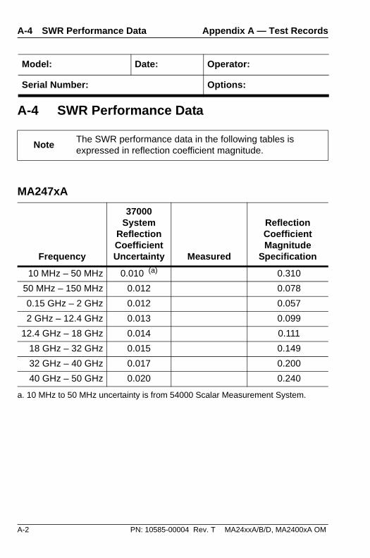
A-4 SWR Performance Data
NoteThe SWR performance data in the following tables is expressed in reflection coefficient magnitude.
MA247xA
Frequency
37000 System
Reflection Coefficient Uncertainty Measured
Reflection Coefficient Magnitude
Specification
10 MHz – 50 MHz 0.010 (a)
a. 10 MHz to 50 MHz uncertainty is from 54000 Scalar Measurement System.
0.310
50 MHz – 150 MHz 0.012 0.078
0.15 GHz – 2 GHz 0.012 0.057
2 GHz – 12.4 GHz 0.013 0.099
12.4 GHz – 18 GHz 0.014 0.111
18 GHz – 32 GHz 0.015 0.149
32 GHz – 40 GHz 0.017 0.200
40 GHz – 50 GHz 0.020 0.240

MA24xxA/B/D, MA2400xA OM PN: 10585-00004 Rev. T A-3
Appendix A — Test Records A-4 SWR Performance Data
Model: Date: Operator:
Serial Number: Options:
MA2472B/D
Frequency
37000 System
Reflection Coefficient Uncertainty Measured
Reflection Coefficient Magnitude
Specification
10 MHz – 50 MHz 0.010 (a)
a. 10 MHz to 50 MHz uncertainty is from 54000 Scalar Measurement System.
0.078
50 MHz – 150 MHz 0.012 0.078
0.15 GHz – 2 GHz 0.012 0.057
2 GHz – 12.4 GHz 0.013 0.099
12.4 GHz – 18 GHz 0.014 0.111

A-4 PN: 10585-00004 Rev. T MA24xxA/B/D, MA2400xA OM
A-4 SWR Performance Data Appendix A — Test Records
Model: Date: Operator:
Serial Number: Options:
MA2400xA
Frequency
37000 System
Reflection Coefficient Uncertainty Measured
Reflection Coefficient Magnitude
Specification
10 MHz – 50 MHz 0.010 (a)
a. 10 MHz to 50 MHz uncertainty is from 54000 Scalar Measurement System.
0.310
50 MHz – 150 MHz 0.012 0.078
0.15 GHz – 2 GHz 0.012 0.048
2 GHz – 12.4 GHz 0.013 0.070
12.4 GHz – 18 GHz 0.014 0.091
18 GHz – 32 GHz 0.015 0.111
32 GHz – 40 GHz 0.017 0.130
40 GHz – 50 GHz 0.020 0.167

MA24xxA/B/D, MA2400xA OM PN: 10585-00004 Rev. T A-5
Appendix A — Test Records A-4 SWR Performance Data
Model: Date: Operator:
Serial Number: Options:
MA244xx (Except MA2442B/D)
Frequency
37000 System
Reflection Coefficient Uncertainty Measured
Reflection Coefficient Magnitude
Specification
10 MHz – 50 MHz 0.010 (a)
a. 10 MHz to 50 MHz uncertainty is from 54000 Scalar Measurement System.
0.310
50 MHz – 150 MHz 0.012 0.078
0.15 GHz – 2 GHz 0.012 0.038
2 GHz – 12.4 GHz 0.013 0.074
12.4 GHz – 18 GHz 0.014 0.095
18 GHz – 32 GHz 0.015 0.127
32 GHz – 40 GHz 0.017 0.180
40 GHz – 50 GHz 0.020 0.200

A-6 PN: 10585-00004 Rev. T MA24xxA/B/D, MA2400xA OM
A-4 SWR Performance Data Appendix A — Test Records
Model: Date: Operator:
Serial Number: Options:
MA2442B/D
Frequency
37000 System
Reflection Coefficient Uncertainty Measured
Reflection Coefficient Magnitude
Specification
10 MHz – 50 MHz 0.010 (a)
a. 10 MHz to 50 MHz uncertainty is from 54000 Scalar Measurement System.
0.078
50 MHz – 150 MHz 0.012 0.078
0.15 GHz – 2 GHz 0.012 0.038
2 GHz – 12.4 GHz 0.013 0.074
12.4 GHz – 18 GHz 0.014 0.095

MA24xxA/B/D, MA2400xA OM PN: 10585-00004 Rev. T A-7
Appendix A — Test Records A-4 SWR Performance Data
Model: Date: Operator:
Serial Number: Options:
MA2481A
Frequency
37000 System
Reflection Coefficient Uncertainty Measured
Reflection Coefficient Magnitude
Specification
10 MHz – 50 MHz 0.010 (a)
a. 10 MHz to 50 MHz uncertainty is from 54000 Scalar Measurement System.
0.310
50 MHz – 150 MHz 0.012 0.078
0.15 GHz – 2 GHz 0.012 0.057
2 GHz – 6 GHz 0.013 0.099

A-8 PN: 10585-00004 Rev. T MA24xxA/B/D, MA2400xA OM
A-4 SWR Performance Data Appendix A — Test Records
Model: Date: Operator:
Serial Number: Options:
MA2481B/D, MA2482A/D
Frequency
37000 System
Reflection Coefficient Uncertainty Measured
Reflection Coefficient Magnitude
Specification
10 MHz – 50 MHz 0.010 (a)
a. 10 MHz to 50 MHz uncertainty is from 54000 Scalar Measurement System.
0.078
50 MHz – 150 MHz 0.012 0.078
0.15 GHz – 2 GHz 0.012 0.057
2 GHz – 12.4 GHz 0.013 0.099
12.4 GHz – 18 GHz 0.014 0.111

MA24xxA/B/D, MA2400xA OM PN: 10585-00004 Rev. T A-9
Appendix A — Test Records A-4 SWR Performance Data
Model: Date: Operator:
Serial Number: Options:
MA249xA
Frequency
37000 System
Reflection Coefficient Uncertainty Measured
Reflection Coefficient Magnitude
Specification
50 MHz – 150 MHz 0.012 0.078
0.15 GHz – 2.5 GHz 0.012 0.057
2.5 GHz – 12.4 GHz 0.013 0.099
12.4 GHz – 18 GHz 0.014 0.111

A-10 PN: 10585-00004 Rev. T MA24xxA/B/D, MA2400xA OM
A-4 SWR Performance Data Appendix A — Test Records
Model: Date: Operator:
Serial Number: Options:
MA2411x
Frequency
37000 System
Reflection Coefficient Uncertainty Measured
Reflection Coefficient Magnitude
Specification
300 MHz – 2.5 GHz 0.012 0.070
2.5 GHz – 26 GHz 0.015 0.149
26 GHz – 40 GHz 0.017 0.200

MA24xxA/B/D, MA2400xA OM PN: 10585-00004 Rev. T A-11
Appendix A — Test Records A-4 SWR Performance Data
Model: Date: Operator:
Serial Number: Options:
MA2421A/D (obsolete)
Frequency
37000 System
Reflection Coefficient Uncertainty Measured
Reflection Coefficient Magnitude
Specification
10 MHz – 50 MHz 0.010 (a)
a. 10 MHz to 50 MHz uncertainty is from 54000 Scalar Measurement System.
0.048
50 MHz – 150 MHz 0.012 0.048
0.15 GHz – 2 GHz 0.012 0.048
2 GHz – 12.4 GHz 0.013 0.070
12.4 GHz – 18 GHz 0.014 0.091
18 GHz – 32 GHz 0.015 0.111
32 GHz – 40 GHz 0.017 0.130
40 GHz – 50 GHz 0.020 0.167

A-12 PN: 10585-00004 Rev. T MA24xxA/B/D, MA2400xA OM
A-4 SWR Performance Data Appendix A — Test Records
Model: Date: Operator:
Serial Number: Options:
MA2468A, MA2469A, MA2469B (obsolete)
Frequency
37000 System
Reflection Coefficient Uncertainty Measured
Reflection Coefficient Magnitude
Specification
10 MHz – 50 MHz 0.010 (a)
a. 10 MHz to 50 MHz uncertainty is from 54000 Scalar Measurement System.
0.310
50 MHz – 150 MHz 0.012 0.078
0.15 GHz – 2 GHz 0.012 0.057
2 GHz – 12.4 GHz 0.013 0.099
12.4 GHz – 18 GHz 0.014 0.111

MA24xxA/B/D, MA2400xA OM PN: 10585-00004 Rev. T A-13
Appendix A — Test Records A-4 SWR Performance Data
Model: Date: Operator:
Serial Number: Options:
MA2468B/D, MA2469C/D (obsolete)
Frequency
37000 System
Reflection Coefficient Uncertainty Measured
Reflection Coefficient Magnitude
Specification
10 MHz – 50 MHz 0.010 (a)
a. 10 MHz to 50 MHz uncertainty is from 54000 Scalar Measurement System.
0.078
50 MHz – 150 MHz 0.012 0.078
0.15 GHz – 2 GHz 0.012 0.057
2 GHz – 12.4 GHz 0.013 0.099
12.4 GHz – 18 GHz 0.014 0.111

A-14 PN: 10585-00004 Rev. T MA24xxA/B/D, MA2400xA OM
A-5 Sensitivity Performance Data Appendix A — Test Records
Model: Date: Operator:
Serial Number: Options:
A-5 Sensitivity Performance Data
Sensor Sensitivity Performance
Sensor Sensor Input Power (dBm)
Actual (dBV) Measured
Sensitivity (dBV)
MA2411A/B +20 +3.6 to +4.3
MA244xx 0 –7.7 to –6.1
MA246xx 0 –7.7 to –5.9
MA247xx 0 –5.7 to –3.9
MA248xx +9 –36 to –33
–7 –36 to –33
–24 –36 to –33
MA249xx +20 +3.6 to +4.3
MA2400xA +10 -29 to -26

MA24xxA/B/D, MA2400xA OM PN: 10585-00004 Rev. T B-1
Appendix B — Specifications
B-1 Technical Data SheetThe latest version of the Technical Data Sheet (Anritsu PN: 11410-00423) for the power sensors listed can be downloaded from the Anritsu Internet site:
http://www.anritsu.com
The data sheet provides the most recent performance specifications for the various models of Anritsu power sensors.
B-2 Performance SpecificationsPerformance specifications for power sensors are also listed here in Table B-1 through Table B-8.

B-2 PN: 10585-00004 Rev. T MA24xxA/B/D, MA2400xA OM
B-2 Performance Specifications Appendix B — Specifications
Standard Diode Power Sensors
Table B-1. Standard Diode Power Sensors (1 of 2)
Parameter/Model Specification
Frequency Range
MA2472A/B/D 10 MHz to 18 GHz
MA2473A/D 10 MHz to 32 GHz
MA2474A/D 10 MHz to 40 GHz
MA2475A/D 10 MHz to 50 GHz
Dynamic Range –70 dBm to +20 dBm
SWR <1.17; 10 MHz to 50 MHz (MA2472B/D only)
<1.90; 10 MHz to 50 MHz
<1.17; 50 MHz to 150 MHz
<1.12; 150 MHz to 2 GHz
<1.22; 2 GHz to 12.4 GHz
<1.25; 12.4 GHz to 18 GHz
<1.35; 18 GHz to 32 GHz
<1.50; 32 GHz to 40 GHz
<1.63; 40 GHz to 50 GHz
Rise Time (a) <0.004 ms
Sensor Linearity MA2475A/D Only All Others
–70 to +15 dBm +15 to +20 dBm –70 to +20 dBm
1.8% <18 GHz 4.8% <18 GHz 1.8% <18 GHz
2.5% <40 GHz 5.5% <40 GHz 2.5% <40 GHz
3.5% <50 GHz 6.5% <50 GHz
RF Connector (b) Type Pin Depth (inches):
MA2472A/B/D N (m) –0.210/–0.207
MA2473A/D K (m) +0.000/–0.002
MA2474A/D K (m) +0.000/–0.002
MA2475A/D V (m) +0.000/–0.002

MA24xxA/B/D, MA2400xA OM PN: 10585-00004 Rev. T B-3
Appendix B — Specifications B-2 Performance Specifications
Maximum Input Power
23 dBm, CW
30 dBm, 1 s peak, ±20 Vdc
Temperature Accuracy (c)
<1.0%, <40 GHz
<1.5%. <50 GHz
a. Rise Time is defined as the time interval necessary for the power sensor to rise from 10% to 90% of the reading when the signal rises instantaneously from zero (no power) to 1 mW (0 dBm) at room temperature.
b. Each power sensor incorporates a precision RF connector with a hexagon
coupling nut for use with an industry standard torque wrench.
c. 5 ºC to 50 ºC
Table B-1. Standard Diode Power Sensors (2 of 2)
Parameter/Model Specification

B-4 PN: 10585-00004 Rev. T MA24xxA/B/D, MA2400xA OM
B-2 Performance Specifications Appendix B — Specifications
Thermal Sensors
Table B-2. Thermal Sensors
Parameter/Model Specification
Frequency Range
MA24002A 10 MHz to 18 GHz
MA24004A 10 MHz to 40 GHz
MA24005A 10 MHz to 50 GHz
Dynamic Range –30 dBm to +20 dBm
SWR
<1.90; 10 MHz to 50 MHz
<1.17; 50 MHz to 150 MHz
<1.10; 150 MHz to 2 GHz
<1.15; 2 GHz to 12.4 GHz
<1.20; 12.4 GHz to 18 GHz
<1.25; 18 GHz to 32 GHz
<1.30; 32 GHz to 40 GHz
<1.40; 40 GHz to 50 GHz
Rise Time (a) <15 ms
Sensor Linearity 1.8% <18 GHz
2.0% <40 GHz
2.5% <50 GHz
RF Connectors (b) Type Pin Depth (inches)
MA24002A N (m) –0.210/–0.207
MA24004A K (m) +0.000/–0.002
MA24005A V (m) +0.000/–0.002
Maximum Input Power
23 dBm, CW
30 dBm,1 s peak, ±20 Vdc
Temperature Accuracy (c)
<1.0%, <30 GHz <+10 dBm <1.5%, 30 GHz, +10 dBm

MA24xxA/B/D, MA2400xA OM PN: 10585-00004 Rev. T B-5
Appendix B — Specifications B-2 Performance Specifications
a. Rise Time is defined as the time interval necessary for the power sensor to rise from 10% to 90% of the reading when the signal rises instantaneously from zero (no power) to 1 mW (0 dBm) at room temperature.
b. Each power sensor incorporates a precision RF connector with a hexagon
coupling nut for use with an industry standard torque wrench.
c. 5 ºC to 50 ºC

B-6 PN: 10585-00004 Rev. T MA24xxA/B/D, MA2400xA OM
B-2 Performance Specifications Appendix B — Specifications
High Accuracy Sensors
Table B-3. High Accuracy Sensors (1 of 2)
Parameter/Model Specification
Frequency Range
MA2442A/B/D 10 MHz to 18 GHz
MA2444A/D 10 MHz to 40 GHz
MA2445A/D 10 MHz to 50 GHz
Dynamic Range –67 dBm to +20 dBm
SWR
<1.17; 10 MHz to 50 MHz (MA2442B/D only)
<1.90; 10 MHz to 50 MHz
<1.17; 50 MHz to 150 MHz
<1.08; 150 MHz to 2 GHz
<1.16; 2 GHz to 12.4 GHz
<1.21; 12.4 GHz to 18 GHz
<1.29; 18 GHz to 32 GHz
<1.44; 32 GHz to 40 GHz
<1.50; 40 GHz to 50 GHz
Rise Time (a) <0.004 ms
Sensor Linearity MA2445A/D Only All others
–67 to +15 dBm +15 to +20 dBm –67 to +20 dBm
1.8% <18 GHz 2.8% <18 GHz 1.8% <18 GHz
2.5% <40 GHz 3.5% <40 GHz 2.5% <40 GHz
3.5% <50 GHz 4.5% <50 GHz
RF Connector (b) Type Pin Depth (inches)
MA2442A/D N (m) –0.210/–0.207
MA2444A/D K (m) +0.000/–0.002
MA2445A/D V (m) +0.000/–0.002
Maximum Input Power
23 dBm, CW30 dBm,1 s peak, ±20 Vdc

MA24xxA/B/D, MA2400xA OM PN: 10585-00004 Rev. T B-7
Appendix B — Specifications B-2 Performance Specifications
Temperature Accuracy (c)
<1.0%, <40 GHz <1.5%, <50 GHz
a. Rise Time is defined as the time interval necessary for the power sensor (when used with ML2480A/B series power meter) to rise from 10% to 90% of the reading when the signal rises instantaneously from zero (no power) to 10 dBm at 25 ºC.
b. Each power sensor incorporates a precision RF connector with a hexagon
coupling nut for use with an industry standard torque wrench.
c. 5 ºC to 50 ºC
Table B-3. High Accuracy Sensors (2 of 2)
Parameter/Model Specification

B-8 PN: 10585-00004 Rev. T MA24xxA/B/D, MA2400xA OM
B-2 Performance Specifications Appendix B — Specifications
Universal Power Sensors
Table B-4. Universal Power Sensors
Parameter/Model Specification
Frequency Range
MA2481B/D 10 MHz to 6 GHz
MA2482A/D 10 MHz to 18 GHz
Dynamic Range CW: –60 dBm to +20 dBm
SWR <1.90; 10 MHz to 50 MHz (MA2481A only)
<1.17; 10 MHz to 150 MHz
<1.12; 150 MHz to 2 GHz
<1.22; 2 GHz to 12.4 GHz
<1.25; 12.4 GHz to 18 GHz
Sensor Linearity <3% 10 MHz to 6 GHz
<3.5% 6 GHz to 18 GHz
<1.8% CW with Option 1
RF Connector (a)
a. Each power sensor incorporates a precision RF connector with a hexagon
coupling nut for use with an industry standard torque wrench.
Type Pin Depth (inches)
N (m) –0.210/–0.207
Maximum Input Power
26 dBm, CW
35 dBm, 1 s peak, ±20 Vdc
Temperature Accuracy (b)
b. 15 ºC to 35 ºC
<1.0%

MA24xxA/B/D, MA2400xA OM PN: 10585-00004 Rev. T B-9
Appendix B — Specifications B-2 Performance Specifications
Pulse Power Sensor
Table B-5. Pulse Power Sensor
Parameter/Model Specification
Compatible with ML2480 (with Option 15) and ML2490 Series Power Meters
Frequency Range
MA2411A/B (a)
a. MA241x sensors must use the ML2480 power meter with Option 15, 1 GHz Calibrator, installed.
300 MHz to 40 GHz
Dynamic Range CW: –20 dBm to +20 dBm
SWR <1.15; 300 MHz to 2.5 GHz
<1.35; 2.5 GHz to 26 GHz
<1.5; 26 GHz to 40 GHz
Rise Time (b)
b. Rise Time is defined as the time interval necessary for the power sensor (when used with ML2490A series power meter) to rise from 10% to 90% of the reading when the signal rises instantaneously from zero (no power) to 10 dBm at 25 ºC.
8 ns typical, 12 ns maximum
Sensor Linearity <4.5% 300 MHz to 18 GHz
<7% 18 GHz to 40 GHz
RF Connector (c)
c. Each power sensor incorporates a precision RF connector with a hexagon
coupling nut for use with an industry standard torque wrench.
Type Pin Depth (inches)
K (m) +0.000/–0.002
Maximum Input Power
23 dBm, CW
30 dBm, 1 s peak, ±20 Vdc
Temperature Accuracy (d)
d. 10 ºC to 45 ºC
<2.0%

B-10 PN: 10585-00004 Rev. T MA24xxA/B/D, MA2400xA OM
B-2 Performance Specifications Appendix B — Specifications
Wide Bandwidth Power Sensors
Table B-6. Wide Bandwidth Power Sensors
Parameter/Model Specification
Frequency Range
MA2490A 50 MHz to 8 GHz
MA2491A 50 MHz to 18 GHz
Dynamic Range CW: –60 dBm to +20 dBm
SWR <1.17; 50 MHz to 150 MHz
<1.12; 150 MHz to 2.5 GHz
<1.22; 2.5 GHz to 12.4 GHz
<1.25; 12.4 GHz to 18 GHz
Rise Time (a)
a. ML2480 Series Power Meter. Rise Time is defined as the time interval necessary for the power sensor to rise from 10% to 90% of the reading when the signal rises instantaneously from zero (no power) to 10 dBm at 25 ºC.
18 ns maximum
Sensor Linearity <7% 50 MHz to 300 MHz
<3.5% 300 MHz to 18 GHz
RF Connector (b)
b. Each power sensor incorporates a precision RF connector with a hexagon coupling nut for use with an industry standard torque wrench.
Type Pin Depth (inches)
N (m) –0.210/–0.207
Maximum Input Power
23 dBm, CW
30 dBm, 1 s peak, ±20 Vdc
Temperature Accuracy (c)
c. 10 ºC to 45 ºC
<1.0%

MA24xxA/B/D, MA2400xA OM PN: 10585-00004 Rev. T B-11
Appendix B — Specifications B-2 Performance Specifications
Thermal Sensors (Obsolete)
Table B-7. Thermal Sensors (Obsolete) (1 of 2)
Parameter/Model Specification
Frequency Range
MA2421A/D 100 kHz to 18 GHz
MA2422A/BD 10 MHz to 18 GHz
MA2423A/BD 10 MHz to 32 GHz
MA2424A/BD 10 MHz to 40 GHz
MA2425A/BD 10 MHz to 50 GHz
Dynamic Range –30 dBm to +20 dBm
SWR <1.90; 10 MHz to 50 MHz (MA2421A/D<1.10)
<1.17; 50 MHz to 150 MHz (MA2421A/D<1.10)
<1.10; 150 MHz to 2 GHz
<1.15; 2 GHz to 12.4 GHz
<1.20; 12.4 GHz to 18 GHz
<1.25; 18 GHz to 32 GHz
<1.30; 32 GHz to 40 GHz
<1.40; 40 GHz to 50 GHz
Rise Time (a) <4.0 ms
Sensor Linearity <1.3%, <18 GHz
<1.5%, <40 GHz
<1.8%, <50 GHz
RF Connector (b) Type Pin Depth (inches)
MA2421A/D N (m) –0.210/–0.207
MA2422A/BD N (m) –0.210/–0.207
MA2423A/BD K (m) +0.000/–0.002
MA2424A/BD K (m) +0.000/–0.002
MA2425A/BD V (m) +0.000/–0.002

B-12 PN: 10585-00004 Rev. T MA24xxA/B/D, MA2400xA OM
B-2 Performance Specifications Appendix B — Specifications
Maximum Input Power 24 dBm, CW
MA242xA 30 dBm, 1 s peak, ±2.2 Vdc
MA2421B/D 30 dBm, 1 s peak, ±2.2 Vdc
MA242xB/D 30 dBm, 1 s peak, ±20 Vdc
Temperature Accuracy(c) <1.0%
a. Rise Time is defined as the time interval necessary for the power sensor to rise from 10% to 90% of the reading when the signal rises instantaneously from zero (no power) to 1 mW (0 dBm) at room temperature.
b. Each power sensor incorporates a precision RF connector with a hexagon coupling nut for use with an industry standard torque wrench.
c. 5 ºC to 50 ºC
Table B-7. Thermal Sensors (Obsolete) (2 of 2)
Parameter/Model Specification

MA24xxA/B/D, MA2400xA OM PN: 10585-00004 Rev. T B-13
Appendix B — Specifications B-2 Performance Specifications
CDMA Power Sensors (Obsolete)
Table B-8. CDMA Power Sensors
Parameter/Model Specification
Frequency Range
MA2468A/B/D 10 MHz to 6 GHz
MA2469B/C/D 10 MHz to 18 GHz
Dynamic Range CW: –60 dBm to +20 dBm
SWR <1.17; 10 MHz to 150 MHz
<1.90; 10 MHz to 50 MHz (MA2468A only)
<1.12; 150 MHz to 2 GHz
<1.22; 2 GHz to 12.4 GHz
<1.25; 12.4 GHz to 18 GHz
Rise Time (a)
a. Rise Time is defined as the time interval necessary for the power sensor to rise from 10% to 90% of the reading when the signal rises instantaneously from zero (no power) to 1 mW (0 dBm) at room temperature.
<0.001 ms
Sensor Linearity CW: <1.8%
RF Connectors (b)
b. Each power sensor incorporates a precision RF connector with a hexagon coupling nut for use with an industry standard torque wrench.
Type Pin Depth (inches)
MA2468A/B/D N (m) –0.210/–0.207
MA2469B/C/D N (m) –0.210/–0.207
Maximum Input Power
23 dBm, CW
30 dBm, 1 s peak, ±20 Vdc
Temperature Accuracy (c)
c. 5 ºC to 50 ºC
<1.0%

B-14 PN: 10585-00004 Rev. T MA24xxA/B/D, MA2400xA OM
B-2 Performance Specifications Appendix B — Specifications

MA24xxA/B/D, MA2400xA OM PN: 10585-00004 Rev. T Index-1
A to S
IndexA
attenuator 1-4, 4-4
Ccalibration 1-5calibration data
EEPROM 1-1storage in sensor 1-1
calibration factor 2-2cleaning 3-10connectors
care 3-3cleaning 3-10, 3-11concentricity 3-4disconnection 3-5non-precision 3-1teflon tuning washers 3-3visual inspection 3-5
customer service 1-6exchange policy 1-6service policy 1-6
EEEPROM 1-1equations
mismatch uncertainty 4-9S11 conversion 4-3
error contributions A-1ESD 1-6exchange policy 1-6
Ffirmware 1-1
Ggauge, pin depth 3-8
Hhard keys, navigation 1-3
Iinspection 3-5IPA 3-3, 3-10isopropyl alcohol 3-10
Mmeasurement uncertainty 4-8mismatch error, uncertainty A-1
Nnavigation, user interface 1-3negative pin depth 3-7
Pperformance 4-1
SWR 4-2pin depth
destructive 3-1, 3-6negative pin depth 3-7
power sensorcleaning 3-3, 3-10elements 4-1ESD sensitivity 3-2excess power 3-2function 4-1mechanical shock 3-2over-torque 3-2problems 4-1
precision connector 3-1
Rreflection coefficient 4-2repair 1-5required test equipment 1-4return loss
conversion 4-3return loss, connectors 3-7
SS11 4-3

Index-2 PN: 10585-00004 Rev. T MA24xxA/B/D, MA2400xA OM
T to V
safety symbolsfor safety Safety-3in manuals Safety-1on equipment Safety-2
sensitivity test 4-4sensor
diode 2-2fast diode 2-5handling 1-5high accuracy diode 2-3linearity 4-8pulse 2-4specifications B-1thermal 2-5universal 2-3wideband 2-4
service 1-6soft keys, navigation 1-3specifications B-1SWR
reflection coefficient 4-2
Tteflon tuning washers 3-3test
data A-1sensitivity 4-4
test equipment 1-4tolerance, connector 3-9
Uuncertainty 4-8
cal factor 4-9cal factor table 4-12error contributions A-1examples 4-10instrument accuracy 4-8mismatch 4-9noise, zero set, drift 4-9reference power 4-9sensor linearity 4-8temperature linearity 4-8
user repair 4-3
Vvisual inspection, connectors 3-5


Anritsu Company490 Jarvis Drive
Morgan Hill, CA 95037-2809USA
http://www.anritsu.com/
Anritsu prints on recycled paper with vegetable soybean oil ink.