m4 journal jeth leong 555136
DESCRIPTION
ÂTRANSCRIPT

1
DIGITAL DESIGN + FABRICATION SM1, 2015 Treeform 2nd Skin
Jeth Leong555136
Rosie Gunzburg

2
Elegant/Fragile/Organic/Modular
The Treeform 2nd Skin

3

4

5
Table of Contents PAGE1.0 Ideation 1.1 Object 6 1.2 Object + System Analysis 8 1.3 Sketch design proposal 9
2.0 Design (Undertaken with Anthony Lee 694830)2.1 Design development 10 2.2 Digitization + Design proposal v.1 112.3 Precedent research 122.4 Design proposal v.2 132.5 Prototype v.1+ Testing Effects 14
3.0 Fabrication (Undertaken with Anthony Lee 694830) 3.1 Fabrication Introduction 15 3.2 Design development & Further Prototyping 163.3 Further Precedent Research 173.4 Design development & Further Prototyping (Cont.) 183.5 Final Prototype development + optimisation 213.6 Final Digital Model 223.7 Assembly Drawing 233.8 Completed 2nd Skin 24
4.0 Reflection 26
5.0 Appendix5.1 Credit 275.2 Bibliography 28

6
1.1 Object:
Eleva
tion V
iew
of Fo
lding
Cha
ir
Plan View of Folding Chair
Plan View of Folding Chair Fabric
Measured drawings of the folding chair in plan and elevation view with the skin and bone systems drawn seperately.

7
To complete the measured drawings, a tape ruler was used to take down important dimensions of the foldable outdoor chair. We were unable to use traditional methods such as photocopy or taking photos due to the large dimensions of the object. Some important dimensions of the object were the footprint (length and width at the base), as well as the height from the ground to the seat and ground to the back rest. These dimensions were taken with the seat in its open and folded position. Also important were the dimensions of the fabric subsystem of the seat, which consisted of two arm-rests and the main body. Photos were also taken in semi plan and elevation view to get an idea of how the object would translate onto paper. In order to acertain certain angles on the metal poles, especially areas where they were bent (at the arm rests) the photos were printed out and angles mea-sured with a protractor. From this information we were able to complete the drawing.
Rhino Model Elevation View
Rhino Model Isometric View
By undertaking measured drawings of the folding chair, one undertakes the mental and physical processes used by the designer of the chair (Heath, Heath and Jensen, 2000). There is a underlying process of understanding the function of each part of the folding chair. By understanding the func-tion, we could apply aspects of the folding chair to our own 2nd skin. With the 3D rhino model, a third industrial revolution (TIR) design process was undertaken, preparing the design for translation into prototype fabrication by automated manufacturing processes (source). This exercise gave us good practice in using 3d modelling tools to place our 2nd skin design into a more workable format.

8
1.2 Object+System Analysis:
Translation of connector along
vertical bar (supports back
rest)
Rotation at joints
of cross connection
between bars
Rotation of bars at joint
with connector
The chair is composed of a skin and bone system, a structure made up of connectors, joints, metal poles, and fabric. My redesigned object is based on a similar premise. There are three movements involved in the “bone” of the chair that facilitate the opening and folding of the chair. This set of par-ticular connector and metal bars works in unison with other connectors and metal bars . The 3 joints in the sketch facilitate rotation with pin joints. The plastic connector and vertical bar facilitate translational motion.
The pencils acted as the “bone” of the object giving the “skin” of the ob-ject, or the poster paper structure by which it could be attached to. The rubber bands act in a similar manner to the connectors and joints on the chair, joining pencils together while allowing some rotational motion while the object was being constructed. The rubber bands also have to purpose of holding the poster paper in place. The criss-cross system of the chair was mimicked as it was found to give the chair and my object self supporting stability. In retrospect the redesigned object should have used less distract-ing materials such as cylindrical wooden poles. However, it was important for the 2nd skin design as an exploration as to how to create rigidity in the structure.
Redesigned Object
Close up of joints system

9
1.3 Sketch Design Proposals:
Sketch Design 3: Adjustable/Tension/Floating
Sketch Design 1: Extension/Panels/Controllable
Sketch Design 2: Circular/Multipur-pose/Retractable
Section of Panel Design
Front View of Panelled Design
One section of the second skin consists of a scis-sor mechanism that extends or retracts a plexi-glass panel. These modules are attached circu-larly around the body and work to increase or decrease personal space according to liking. The sharp defined edges of the second skin act as a visual warning to maintain distance.
Retracted Design
Extended Design
Second skin starts as a hat. When the person does not require a barrier to protect their personal space, this mode of usage is most suitable. When unhooked drapes over body to create personal space in an efficient manner. The combination of translucent fibers and plastic bands provide structure to the second skin.
Piston like modules with three adjustable levels of support and provide tension to a clear synthetic layer. Different levels of support provide greater tension to the layer and also greater space. The increasing stretch marks across the layer accord-ing will dissuade strangers from coming clos-er.
Section of Retracting Design
Side View of Retracting Design

10
2.1 Design Development (Undertaken with Anthony Lee 694830):
Chosen Sketch Design Side View
Chosen Sketch Design Back View
Chosen Sketch Design Front View Open
Chosen Sketch Design Front View Closed
Our sketch designs were based on the skin and bone system. We chose a design that embodied our concept of 2nd skin the most. In reflection of my earlier sketch designs (as seen in section 1.3), it appeared that I got ahead of myself in the ideation by designing 2nd skins based on already existing everyday systems in real life. The results were that the sketch designs were not very inventive and did not convey my true intentions for the 2nd skin. In-stead, I should have brainstormed for designs based on my criteria for a 2nd skin and then constructed a system related to the foldable chair from it.
At this stage we developed a chosen sketch design. First, we translated our design from paper into Rhino. Next, we adapted our design into devel-opable surfaces so they could be fabricated as prototypes. We laser cut pieces and built a few prototypes adapted from our design.
Our chosen design consisted of several curved arms repeated and rotated around the upper body. These arms could be adjusted based on the per-sonal space criteria of the individual. They could folded in and out based on the comfort level of the person. Based on Anthony’s criteria the arms would enclose more of the left side of the body while opening up more of the right side of the body to facilitate the use of the dominant hand. The idea is that the personal space created by the 2nd skin is modular and fluid, changing between situations. Also the purpose of the 2nd skin is to enclose the outside world from you and not to enclose you from the outside world. The outside world should still be accessible to the user.

11
2.2 Digitization + Design proposal v1.:
Plan View
Elevation View
Side View
We modelled V1 of our proposed 2nd skin design in Rhino. The design explored the concepts that we were aiming for in our piece. However, the feeling of the V1 Rhino model was that it was very much a preliminary idea. Based on the model, it was hard to decide which material and fabrication method would be suitable due to the undevelopable nature of the surfac-es. Also nothing had yet been designed in terms of ideas of how to secure the design to the body. Finally, it was hard to decipher how a skin and bone system would work with the modelled design. There was no joint system to govern each arm of the system, and there was no interaction by fabric or other means between the arms.

12
2.3 Precedent research:
SS2012 “11:11” Collection-Winde Rienstra. 2011
Close up of two wood sections connected by string
Close up of joint connection to wood waist support
Notched Joint
Elevation Sketch of Precedent Design
Tensegrity, Transparency, Encasement, Interlocking, Cage
The “11:11” Collection is a collection of clothing for Spring/Summer 2012 by Winde Rienstra that was exhibited during Amsterdam Fashion Week. This particular piece from the collection uses thin, laser cut wood pieces ar-ranged to form a shell around the upper body. The strings that interconnect the wood pieces add shape and volume to the structure while allowing the inner body to be seen. The tension with the strings constrasts with the compression in the wooden pieces, providing tensegrity and energy not usually seen in clothing. A wood waist support with notched joints holds the rest of the structure onto the body. The elegant nature of the design gave ideas on incorporating the same thin but rigid elegance to our own 2nd skin design.
13
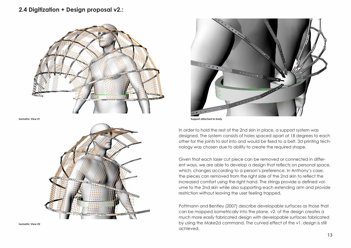
2.4 Digitization + Design proposal v2.:
Isometric View #1
Isometric View #2
Support attached to body
In order to hold the rest of the 2nd skin in place, a support system was designed. The system consists of holes spaced apart at 18 degrees to each other for the joints to slot into and would be fixed to a belt. 3d printing tech-nology was chosen due to ability to create the required shape.
Given that each laser cut piece can be removed or connected in differ-ent ways, we are able to develop a design that reflects on personal space, which, changes according to a person’s preference. In Anthony’s case, the pieces can removed from the right side of the 2nd skin to reflect the increased comfort using the right hand. The strings provide a defined vol-ume to the 2nd skin while also supporting each extending arm and provide restriction without leaving the user feeling trapped.
Pottmann and Bentley (2007) describe developable surfaces as those that can be mapped isometrically into the plane. v2. of the design creates a much more easily fabricated design with developable surfaces fabricated by using the Make2d command. The curved effect of the v1. design is still achieved.

14
2.5 Prototypes + Testing Effects:
Isometric View of Tested Section
Demonstration of Effects of Tested Section
Initially, two different pieces were used to make up our 2nd skin design. The straight piece with notched joint connections formed the basis of our design. The holes would allow us to thread string through and add another level of support to our 2nd skin. The angled connector provided our design with the means to curve while building upwards.
With the created section, we decided to connect the strings laterally across the holes to explore the material effects. As the entire section is bent in-wards, the inner most strings lose tension followed by the outer strings. This is an effect that we explored further in our 2nd skin design. Another unintend-ed effect was that the longer the curve created the greater the bending effect would take place
Although the pieces and prototype section were a good start, our 2nd design was too straightforward and more pieces were needed to spruce up the design. We decided to undertake a more hands-on approach of experimenting designs with our given pieces instead of creating our designs in Rhino.
3D model of straight connector Laser cut straight connector
3D model of angled connector Laser cut angled connector

15
3.1 Fabrication Introduction (Undertaken with Anthony Lee 694830):
From our design stage, we realized that we still had a lot of work to do. We decided to scrap the v2. design proposal and instead ex-perimented with design through building. We decided that we needed more pieces to achieve our desired effects of elegance and fragility but rigidity with our second skin. We also wanted to also maintain the theme of modularity in our system and the malleability of the 2nd skin around the body. We also had to design a new method of attaching the system to our body that was in matched the theme of elegance. It had to less bulky and more streamlined with the body.
The two pieces we created from the design stage

16
3.2 Design Development & Further Prototyping:
Rhino Model of “Y” Connector
Laser Cut “Y” Connector
Rhino Model of “y” Connector
Rhino Model of “y” Connector
We decided to create more pieces which would allow each arm to become sub-branches adding another level of complexity as well as making our de-sign more organic and tree like. By designing the pieces in rhino but not the entire design we could experiment and build our 2nd skin in realtime. This way we could test the effects and material properties much more accurately and effectively. The two connectors chosen to be made were the “Y” connector and “y” connector and were laser cut on 3mm MDF.

17
3.3 Further Precedent Research:
Treeform Architecture
Tree structure, model, Frei Otto, 1982
Stuttgart Airport Roof, Von Gerkan Marg & Partners, 1939
Aviary, Group 8 with Guscetti & Tournier, 2008
Frei Otto was known for his treeform structures; structures which are based on the natural form of the tree where its foiliage serves as the roof of the structure and the branches act as the support structure. Frei Otto was in-terested in these structures due to how little material they used compared to the rigidity they offered. He built this model upside down and flipped it around. There is an elegance associated with the slender bases of the struc-ture supporting the roof.
Architects of the Stuttgart airport similar explored to use of complex fractal steel trees to support the roof of their terminal. Loads are transmitted from the roof of the building through the branches to the trunk of the structure.
The Aviary is structure designed as a display for birds in Geneva. The shape of trees was decided based on abstract analysis of the surrounding trees in the public park. This allows the structure to fit in aesthetically with its natural surroundings.
Based on these different examples of treeform architecture, we decided that treeform was a lightweight, elegant and rigid element that our 2nd skin design could use. By applying simple rules we could create complex struc-ture.

18
3.4 Design Development & Further Prototyping (cont.):
Body-Skin Interface-2nd Iteration
Belt Supports-2nd Iteration
Body-Skin Interface and Belt Support Laser Cut Prototype
Laser Cut Body-Skin Interface Connected to Belt Supports
The second iteration of the body-skin interface applied a more traditional notched joint approach, allowing for a more secure connection to the branches of the skin. It also fits in with the thin, light and low profile vision for the 2nd skin. The circular holes allow for ability to tie string for further support of the 2nd skin. In the rectangular section of the interface are 2 sets of rectanglar holes for the belt supports to notch into. Belt supports have two notches to connect to the interface. A belt can be threaded through the supports and fastened to the body to support the 2nd skin.

19
Repeating Pattern Side View
Repeating Pattern Top View
With all the different pieces cut out we were able to decide on a particu-lar base pattern to reuse all over our skin. By creating this rule we would be able to create a more complex design. We decided on this design due to earlier testing where longer branches would bend under the stress of their own weight. By keeping the pattern short we could repeat it through branching and distribute stress evenly across the skin. This pattern also added gave our 2nd skin a more organic tree branch effect.
The Basic Rule V1:Straight Connector=IAngle Connector=<
“y” Connector=y“Y” Connector=Y
-<-II-y-Y
-<-I

20
We experimented connecting our pattern to the skin-body interface for our version two second skin prototype. Once again we were faced with bending problems as the branches grew longer. We used string to connect adjacent branches together and provide support for the side to side sway-ing. However, the solution of cotton twine did not seem elegant and in line with the desired thin branching effect. Also, there was still a lot of unstable movement in the branches. This is due to the fact there is no “roof” to stabi-lize each branch.
We stumbled upon using solely the laser cut pieces to stabilize the 2nd skin with the final version of the 2nd skin prototype by using the y connec-tor and a pair of angle joints to connect adjacent branches together. This gave the structure more stability and also created an aesthetically pleas-ing leaf shape. The design also utilized the bending capabilities of the MDF, which became more pronounced as branches were connected to other branches not in the same plane. Building on this idea, we added a rule to our design that branches in our 2nd skin should always be connected to other branches that do not originate from the same starting point. This was the basis for our final 2nd skin.
Section of Version 2 Second Skin Prototype Section of Version 3 Second Skin Prototype

21
3.5 Final Prototype development + optimisation:
Laser Cut Template
As many pieces were placed on the template as possible and lines were shared between pieces to ensure material wastage was kept to a minimum and the laser cutting process was the most cost effective. The material chosen was 3 mm MDF due to the low cost as compared to other materials such as plywood. Extra pieces were cut out to ensure there were enough replacement in the event of snapping pieces. The Notches on each piece were 3 mm thick to match the thickness of the mdf when connected to op-posing pieces. This ensured that there was no play between the pieces.
The Basic Rule Final:Straight Connector=IAngle Connector=<
“y” Connector=y“Y” Connector=Y
-<-II-y-Y
-<-I-<-I-<-I.....<- Y
-<-I-<-I-<-I.....<-I-y-Y
-<-I
Based on V1 of the rules, the final edition of rules added a string of straight connectors and angle connectors of indeterminate length in order fi-nally joining together with a Y connector. This set of rules allowed different branches to be connected together, adding stability and complexity to the system. These rules also gave the opportunity to create a non-symmetric design catered to the personal space constraints of the user.

22
3.6 Final Digital Model:
Branching into two layers
Using one outlet “y” connector as described in the rules, one could create further sub branches by repeating the rule again. For our design, we cre-ated four layers based on the basic rules.
Front View Side View
Isometric View
It was difficult to model our design due to the bending nature of our mate-rial. The actual finished 2nd skin would look different as there was no way to predict the bending nature of the materials within rhino, a limitation of the software. As we continued building in rhino, the pieces would not match up as they did in the final 2nd skin design.

23
3.7 Assembly Drawing:
Initial Assembly of Skin Body Interface to angle and straight connectors
Assembly of Basic Rule of 2nd Skin Design
Rhino model vs. real life model differences
The Rhino model does not account for any bending in the material. The red circle regions show how critical points do not connect as they do with the real world 2nd skin design due to lack of bending taking account. Thus the rhino model shows how the pieces are like without any deformation. From this model we observed that most areas of our design cannot be connect-ed without a certain degree of flex from the material, an element is crucial to our design.
Isometric view of 2nd Skin Design as a result of unbendable pieces

24
3.8 Completed Second Skin:
Completed 2nd Skin Rear View

25
The 2nd skin is attached to the user at the waist. It wraps around the back and the extends over the head and around the left arm. The right arm is free to operate. This is to facilitate the personal space of Anthony. The branches grow out like tree branches with specific rules in multiple layers and follow the contour of the body. The modular nature of the design allows the user to create a 2nd skin catering to their own personal space.
Fishing wire is crisscrossed like a spider web throughout the branches to add another barrier of protection from the outside world, additionally providing sup-port to the branches. The lightweight and transparent design allows the user to move freely while not hindering their personal space.
The finalized design portrayed the elegant light weight and natural theme of the 2nd skin. Personal space is not something that is constructed, it “grows” according to the users the preference. The fragile branches are not meant to hinder the user, but to provide a light shield of personal space.
Completed 2nd Skin Front View Completed 2nd Skin Side View
26
4.0 Reflection:
During the overall design process, it was very much an exercise in learning as you go. Having taken this subject with no prior experience in graphic design and coming from an engineering background, it was hard to adjust to thinking about form as well as function. This is was very much evident in the ideation stage, where many of my sketch models were too focused on how they would work rather than they would look and achieve their purpose. Even though I have learnt modeling through rhino, it feels very much like I have only just dipped my feet in the water, as there is so much more to learn.
Choosing the foldable chair made me semi decent at creating real life objects in rhino, but I did not take advantage and learn other more useful tools in rhino such as paneling tools. Through the design and fabrication stages, we modified our design according to the tutor’s feedback, and really experimented and allowed our design to take its own shape. What was most successful about our design was how through simple rules and just 4 different connectors to our design, we were able to create a complex yet elegant 2nd skin. It was interesting to see how there was no single step-by-step recipe in embarking on this journey. While some groups focused on their modeling aspect, making beautiful models in rhino, before transitioning into fabrication, we chose to jump straight into fabrication and experiment from there, working backwards later. This shows that although rhino was an important aspect of the design process, for us the making process was the most important. With that being said, the modeling aspect of our design was the weakest aspect of our design. It was quite hard to adapt our fabricated 2nd skin back into rhino due to material properties that were not portrayed in rhino. However, I feel that if we spent more time attempting to model and use the bend command to bend the pieces to connect together, we may have had more success in the modeling process. Also, we could have experimented using grasshopper, inputting our rules and seeing how our design would grow.
The advent of digital technology has really improved the accessibility of embarking on design processes. We were able to draw on other ideas found on the internet as inspiration, other precedent studies adapt to our 2nd skin. The Internet was also an important tool for learning, as we would always turn to google if we didn’t know how to use a command in rhino. The digital revolution along with lateral economies of scale allowed us to easily translate 3d models into fabricated parts through additive and subtractive manufacturing with low turnaround times (Rifkin, 2011). In a world where digital technology delivers greater certainty, design risk, or risks that come with alternative outcomes give craft a role as a mediator between humans and technology (Deamer and Bernstein, 2010). Our design undertook design risk as we were not constrained by the digital environment, instead choosing to explore our design through creating individual pieces that digitally modeled and fabricated by machine, and creating alternative outcomes by utilizing the material properties.

27
5.1 Credit:
Page Drawings Computation Model Fabrication Model Assembly Photography Writing Graphic Design
Cover
!!
6 !
7 ! ! !
8 ! ! !
9 ! !
10 ! !!
11 ! !
12 ! !
13 ! !!
14 !! ! ! !! !
15 !! ! !
16 !! ! ! !
17
!
18 !! ! ! !
19 ! ! !
20 ! ! !
21 ! !!
22 !! !
23 !! !
24 !! !! !
25 !! !! !
26 !
Student name Jeth Leong
Student name Anthony Lee

28
5.2 Bibliography:
Deamer, P. and Bernstein, P. (2010). Building (in) the future. New Haven: Yale School of Architecture.
Heath, D., Heath, A. and Jensen, A. (2000). 300 years of industrial design. London: Herbert.
Pottmann, H. and Bentley, D. (2007). Architectural geometry. Exton, Pa.: Bentley Institute Press.
Rifkin, J. (2011). The third industrial revolution. New York: Palgrave Macmillan.
SS20
12 “
11:1
1” C
olle
ctio
n-W
ind
e R
iens
tra
. 201
1St
uttg
art
Airp
ort
Ro
of,
Vo
n G
erk
an
Ma
rg &
Pa
rtne
rs, 1
939
Tre
efo
rm 2
nd S
kin
Bac
k V
iew