m2 antenna systems, inc. model no: 10-30lp8 manuals/logs hf/10-30lp8man02-w...m2 antenna systems,...
TRANSCRIPT

M2 Antenna Systems, Inc. 4402 N. Selland Ave. Fresno, CA 93722 Tel: (559) 432-8873 Fax: (559) 432-3059 Web: www.m2inc.com
©2014 M2 Antenna Systems Incorporated 11/06/14 Rev.02
Model ........................................ 10-30LP8 Frequency Range ...................... 10-30 MHz Continuous *Gain free space / 65’ .............. 5.2 dBi / 10.5 dBi 10-30 Front to back .............................. 15 dB 10-30 MHz Beamwidth ............................... E=70° Typical Feed Impedance........................ 50 Ohms Unbalanced
Maximum VSWR ....................... 2.0:1 Input Connector ......................... SO-239, Others avl.
Power Handling ......................... 3 Kw, Higher avl. Boom Length / Dia ..................... 29.5’ / 3.0 x .125 Wall Maximum Element Length ......... 49’ Turning Radius: ......................... 28’ Mast Size ................................... 2” to 3 ” Nom. Wind area / Survival .................. 12.5 Sq. Ft. / 100 MPH Weight / Ship Wt. ....................... 100 Lbs. / 125 Lbs.
M2 Antenna Systems, Inc. Model No: 10-30LP8
FEATURES: Twenty years of log periodic engineering and field experience have gone into the design of the 10-30LP8 HYBRID log periodic. The result is a rugged, versatile antenna with excellent performance over a 20 MHz bandwidth. It’s designed for years of trouble free service, featuring machined, 1/2” thick element-to-boom clamps, massive solid fiberglass rod cen-ter insulators, stainless steel hardware, and elements sleeved to achieve at least the 100 MPH wind survival rating. A broadband 3000 Watt 4:1 ferrite balun is supplied. Maritime, Government, Commercial, MARS, Amateur Radio communications and Shortwave listening are among 10-30LP8’s many, many uses. For receive only, it works extremely well from 1 to 100 MHz. This log will survive many years of all Mother Nature has to offer and continue to provide top performance with minimal maintenance. Stack with the 6-10LP5 for complete, efficient coverage from 6 to 30 MHz.
SPECIFICATIONS:
*Subtract 2.14 from dBi for dBd

BEFORE YOU BEGIN: Look over the DIMENSION SHEET, HARDWARE AND ELEMENT ASSEMBLY DRAWINGS to get familiar with the various parts of the log periodic. Tools handy for assembly process: screwdriver, 11/32, 7/16, 1/2, 9/16 and 5/8” spin-tites, end wrenches and/or sockets, measuring tape. A small container of zinc paste (Penetrox, Noalox, or equiv.) has been provided to enhance and maintain the quality of all electrical junctions on this antenna. Apply a thin coat wherever two pieces of aluminum come in contact or any other electrical connections are made. 1. DESCRIPTION OFTHE ELEMENT CLAMP PLATES. ALSO SEE HARDWARE DRAWINGS. Three types of clamp plates pairs are supplied to fit three diameters of fiberglass rod insulators
found at the center of elements #1 through #7. Pair them up as follows: A. Two 3 x 6 x 1/2” plates, milled with a 5/8” radius channel, are for ELEMENT #1 (the rear linear
loaded element) and clamp a 1-1/4" x 24" fiberglass rod. B. Four other 3 x 6 x 1/2” clamp plates, milled with a 1/2” radius channel, are for ELEMENTS #2
AND #3 and clamp 1” x 24” fiberglass rods. C. Elements #4 through #7 use a single 2-1/2 x 4 x 3/8” plate and a matching rectangular 1-3/4 x
4 x 1/4" clamp plate, and clamp 7/8 x 29-3/4 inch long fiberglass rods. (Elements #4, 5, 6, and 7 use a single bottom cradle each).
D. The front director element mounts differently, using two clamp cradles as described in step 9. 2. Start by assembling the two 1-1/4” rod CLAMP PLATES together with 1/4-20 x 2-1/2" bolts to the
six holes. Add the 1/4-20 locknuts finger tight. Slip in the 1-1/4 X 24" fiberglass rod and rotate until the element mounting holes are vertical. Center the rod and tighten the clamp hardware EVENLY, so the plates are parallel and the same amount of threads are showing through all the locknuts.
3. Assemble the clamp plates pairs of ELEMENTS #2 & #3 with SIX 1/4-20x2-1/2" bolts and locknuts
and a 1” x 24” Fiberglass rod, each. The clamp plate pairs for next four elements (#5, 6, 7, 8) require FOUR 1/4-20x1-3/4" bolts and locknuts and a 7/8” x 29-3/4” Fiberglass rod.
4. Now slide a POLYETHYLENE DISC INSULATOR (1-1/4”, 1” or 7/8” internal Dia.) onto each end of
ALL the fiberglass rods and push them up against the clamp plates. 5. MOUNTING INNER ELEMENT TUBING SECTIONS TO ELEMENT CLAMP ASSEMBLIES #1
THROUGH #7. REFER TO DIMENSION SHEET AND HARDWARE ASSEMBLY DRAWINGS. A. Inner element tubing sections have 1/4” holes in their straight (butt) ends. Pair up by diameter.
To prepare the inner element sections for the PHASING LINE CLAMP ASSEMBLIES, apply a little zinc oxide paste to the last inch of each element butt. Also apply a little paste to the channels in all the small PHASING LINE CLAMP PLATES and the larger PHASING LINE CLAMP BLOCKS. This paste inhibits corrosion and helps to assure a reliable, low loss joint for many years.
B. Loosely assemble plates to blocks, channel to channel, with 1/4-20 x 1” FLATHEAD SCREWS
AND LOCKNUTS. Loosely install an 8-32 screw and locknut through block clamp fingers using 8-32 x 1-1/2” screws for 1” clamps, 8-32 x 1-3/4” screws for 1-1/4” clamps and 8-32 x 2” screws for the 1-1/2” clamps. Install a PHASING LINE CLAMP BLOCK assembly onto the end of each element butt with small clamp plate oriented to element butt.
10-30LP8 ASSEMBLY MANUAL

6. A. On element #1, slide 1-3/8” x 24” sleeve over the 1-1/4” fiberglass rod end and align the 1/4” holes. Then add the 1-1/2” x 60” inner element section over the sleeve and rod, align the holes and add a 1/4-20 x 2” bolt and locknut. Tighten securely. Repeat for the other inner element half.
B. Repeat for elements #2 and #3 using 1-1/8” x 24” sleeves on the fiberglass rods, 1-1/4” x 60”
inner element sections, and 1/4-20 x 1-3/4” bolts and locknuts. C. Install the 1” x 60” inner element sections of elements #4 through #6 directly to the 7/8”
fiberglass rod insulators with 1/4-20 x 1-3/4” bolts and locknuts. Set element / clamp assemblies aside for now.
D. For Element #7 attach the 1 x 1 x 4” Balun L-Bracket to the top two holes on one of the
element clamp plates using two 1/4-20 x 2” bolts. Insert to 1/4-20 x 1-3/4” bolts in the bottom two holes. Insert the remaining 7/8 x 29-3/4” Fiberglass rod and secure all 1/4-20 hardware. See the drawing HARDWARE ARRANGEMENT FOR ELEMENT #7.
7. BOOM ASSEMBLY (THREE SECTION BOOM) Inspect the drilled ends of the boom sections for any aluminum chips
or dirt. Wipe out with a clean rag. The straight section is the CENTER boom section. Slide the sections with the necked down end (swage) into the straight section. Align the holes and add the 1/4-20 x 3-1/2" bolts and locknuts. Tighten securely until no lateral movement occurs in the joints. (TWO SECTION BOOM) Wipe off the swaged end of the rear boom section. Now slide the other 15’ boom section over the swage. Align the holes and add the hardware. Once all the bolts are in, tighten the nuts until the boom sections firm up and no joint movement is felt when wiggling the boom.
B. Install the 3/8 EYEBOLTS to the outer ends of the boom, securing with stainless 3/8-16 nuts
and lock washers. Align the eyes parallel with the boom and tighten. 8. Orient the boom with the eyebolt eyes "up”. The boom end with the eyebolt at 52” from end is the
“REAR”. Using a tape measure and a marking pen or masking tape, place a mark 1/2” in from the rear of the boom. This will be where you position the back edge of the clamp plate for element #1. Now measure forward 78.75” (6’ 6-3/4”) from that mark and make another mark. Call this position element #2. Continue marking the locations of all the elements using the element spacing figures given on the Dimension Sheet.
9. Attach the Element #1 element / clamp assembly to the boom. For ease of installation, support the
boom about 3’ above ground, eyebolts "up." Loosely attach two BOTTOM CRADLES to the bottom of the clamp plates using the 1/4-20 x 2-3/4" hardware. Slip Element #1 over the rear of the boom, placing the back edge of the rear plate on your first 1 inch mark. With the eyebolt in the boom vertical, adjust the inner element sections to the horizontal and tighten the cradle bolts securely.
10. Mount the next element / clamp assemblies with 1” fiberglass rods in element position #2 and #3.
First place the clamp plates on the boom at the mark and then add the two bottom cradles and 1/4-20 x 2-3/4" bolts. Align with the first element clamp and tighten gently.
11. Mount the clamp plates with the 7/8 inch diameter fiberglass rods, again positioning each clamp at
the mark, aligning with the first element and tightening. These elements require only one cradle. 12. A. Now mount the DIRECTOR ELEMENT. Insert the 3/4” x 60” element sections into the 7/8 x 30"
center tube, align the holes and drop through two 1/4-20 x 5" bolts. Install an inverted cradle onto the bolts and up against the 7/8" sleeve section. Place this assembly on the boom. Add the bottom cradle, locknuts, then align elements and tighten nuts.
10-30LP8 ASSEMBLY MANUAL

13. INSTALLING THE PHASING LINES. SEE DIMENSION SHEET & HARDWARE ASSEMBLY DRAWINGS
A. Start with the shortest set between element #6 and #7. For each set, feed the phasing lines through a 3/4” x 3” DELRIN SPACER so that the spacer sits at the crossover point between the lines. Hold the spacer in place loosely around the boom with a large nylon tie but don't tighten it yet. Adjust phasing lines so that their bends are even and the lines run parallel to the boom.
B. Apply a small amount of conductive paste to the rod ends and feed the #7 ends into the clamp block channels until 1/4” extends beyond clamp. Tighten the 1/4-20 x 1” flathead screws and locknuts on element #7. Then adjust the block assemblies flush to the disc insulators and tighten 8-32 clamp screws. Insert the other rod ends into the clamp block assemblies on element #6 but do not tighten. Continue to the next phasing line set between element #5 and #6. Apply paste and insert the ends into the clamp blocks at element #6 and NOW tighten the flathead screws and nylon tie. While installing the phase lines, you might find that some of them will extend 1 - 2” past their respective clamp blocks. This is OK. You can trim them back, in order to fit flush with the clamp block faces, if you desire.
C. Continue in the same fashion tightening the hardware and nylon ties as you go. Note the
phasing lines between elements #3 and #4, the bends in this set of phasing lines are offset, with the crossover point closer to element #3. The phasing lines between elements #2 and #3 are offset, with the crossover point closer to element #3.
D. Attach the 16 turn COIL to element #1 1/4-20 x 1” screw studs before securing phasing lines. 14. MOUNTING THE 4:1 BROAD BAND BALUN. Secure the BALUN to the 1 x 1 x 4" BALUN L-BRACKET MOUNTING PLATE with a 2-1/2" U-bolt
and cradle. DO NOT OVERTIGHTEN - BALUN HOUSING COULD BE DAMAGED! Position balun with the connector pointing towards the rear of the boom and leads easily reaching phasing line clamp block screw studs. Now remove the 1/4 inch nuts from the clamp block screws. Apply some zinc paste to the lugs on the balun leads and place over each screw stud. Replace the nuts and retighten.
15. Attach the BOOM TO MAST PLATE with the two large 3 inch U-bolts. Center it at the Delrin
standoff between element #3 and #4. Reshape the phasing lines as needed to clear the plate by at least 1/2”.
16. OVERHEAD BOOM SUPPORT SYSTEM. A. Attach one end of the 5/16" Dacron cord to the rear eyebolt using two turns around the eyebolt
and a series of three half hitches or equivalent knots. Without cutting the cord do the same at the front eyebolt. Pull on the knots HARD to SET them and tape the excess cord back to main cord tightly with black vinyl electricians tape. Seal ends with heat or flame to prevent fraying.
B. TEMPORARILY insert a 2 inch U-bolt through the turnbuckle plate and add two nuts so about
1/2 inch of the threads stick out. Insert this assembly through the top set of 2” U-bolt holes in the boom to mast plate from the boom side and add two more nuts. Open the two turnbuckles up until just a thread or two from each end protrudes inside the body of the turnbuckle. Hook the turnbuckles into the holes at the edge of the turnbuckle plate. Equalize the Dacron cord over the plate and cut it. Take two wraps of the cord through the eye of the rear turnbuckle, PULL the cord as tight as possible and make the knots as before. Repeat for the front cord section and turnbuckle. Cut off any excess over one foot long and again seal and tape the excess cord back to the main cord.
C. Now DISASSEMBLE the U-bolt from the boom to mast plate. The guy assembly is now
centered and ready to be raised up the mast and adjusted to level the boom during the final installation. The turnbuckle plate, installed loosely with a 2” U-bolt, can be raised up the mast until the boom is straight.
10-30LP8 ASSEMBLY MANUAL

D. If practical, after the final assembly steps below and before installation, let the overhead guy system support the boom and take a set overnight: Install a 2’ to 3’ temporary 2” mast section to the boom to mast plate and attach and raise the turnbuckle plate. Support the antenna at the boom to mast plate. The Dacron cord DOES NOT STRETCH UNDER THIS LOAD but it will take a SET and the boom may droop just a bit. Reset turnbuckle plate. If your boom droops again following this adjustment, check your knots. They may be may be slipping.
E. After final installation, do any final boom straightening with the turnbuckles. Then safety wire to prevent changes to settings.
17. OUTER ELEMENT AND TIP SECTION ASSEMBLY. (SEE THE DIMENSION SHEET) A. All the outer tubing sections with swaged (necked down) ends are 5’ (60”) long . Only the
straight element tip sections are non-standard lengths. Assemble all outer element and tip sections for elements #1 through #8 using the Dimension Sheet as reference. The hardware to join the various tubing sizes are as follows:
For 1" to 3/4" tubing use 8-32 x 1-1/4" screws. For 3/4" to 1/2" tips use Compression Clamps with 8-32 x 1/2 screws and nuts. (SEE COMPRESSION CLAMP & TIP ASSEMBLY DETAIL) Locknuts have been provided for all the element assembly screws. Tighten the nuts and
compression clamps until the joint doesn't move when wiggled or shook. 18. Check ALL hardware for tightness. Check ALL element sections, especially tip sections, for correct
exposed length and placement. 19. Attach feedline section to balun. Route around element #7 and back to boom to mast plate. Secure
at regular intervals with tape or nylon ties. 20. When mounting this log periodic on a tower or mast with other antennas there may be interaction
with other nearby antennas, particularly if they are resonant in the 10 to 30 MHz band. In general VHF and/or UHF antennas mounted for HORIZONTAL POLARITY should be at least 40 inches above or below the log antenna. Use good quality 50 Ohm feed line to feed the log and be sure your tower and rotator system can handle to wind area and weight of this antenna.
THIS COMPLETES ANTENNA ASSEMBLY
CAREFULLY DESIGNED AND MANUFACTURED BY:
M2
ANTENNA SYSTEMS, INC. 4402 N. SELLAND AVE.
FRESNO, CA 93722 (559) 432-8873 FAX: 432-3059
www.m2inc.com Email: [email protected]
10-30LP8 ASSEMBLY MANUAL

10-30LP8 DIMENSION SHEET

10-30LP8 ASSEMBLY DETAILS
ELEMENTS #4 — #6
ELEMENTS #1 — #3

10-30LP8 ASSEMBLY DETAILS
ELEMENT #8
ELEMENTS #7

GENERIC COMPRESSION CLAMP DETAIL

DESCRIPTION .......................................................... QTY Boom section, 3 x .125 x 180" SWAGED ........................................ 1 Boom section, 3 x .125 x 180" STRAIGHT ..................................... 1 Sleeve, Director 7/8 x .058 x 30 ...................................................... 1 Sleeve, 1-3/8 x .058 x 24" ............................................................... 2 Sleeve, 1-1/8 x .058 x 24” ................................................................ 4 Element butt section, 1-1/2 x .058 x 60" SOE, ................................ 2 Element butt section, 1-1/4 x .058 x 60" SOE 1/4" hole ................. 4 Element section, 1-1/4 x .058 x 60 SOE ........................................ 2 Element section, 1.0 x .058 x 60 SOE ............................................. 6 Element butt section, 1.0 x .058 x 60" SOE 1/4" hole ...................... 8 Element section, 3/4 x .049 x 60" SOE ............................................ 6 Element butt section, 3/4 x .049 x 60" SOE 1/4" hole ..................... 2 Element tip section, 3/4 x .049 x 73.00" .......................................... 2 Element tip section, 3/4 x .049 x 62.25" .......................................... 2 Element tip section, 3/4 x .049 x 38.50" .......................................... 2 Element tip section, 3/4 x .049 x 22.5" ............................................ 2 Element tip section, 1/2 x .049 x 67.0" ............................................ 2 Element tip section, 1/2 x .049 x 62.50" .......................................... 2 Element tip section, 1/2 x .049 x 40.25" .......................................... 2 Element tip section, 1/2 x .049 x 24.5" ............................................. 2 Rod, phasing, 3/16 x 83.75" ............................................................ 2 Rod, phasing, 3/16 x 72.375" .......................................................... 2 Rod, phasing, 3/16 x 59.25" ............................................................ 2 Rod, phasing, 3/16 x 48.5" .............................................................. 2 Rod, phasing, 3/16 x 41.0" .............................................................. 2 Rod, phasing, 3/16 x 35.0" .............................................................. 2 Rod insulator, 1-1/4 x 24" fiberglass ................................................ 1 Rod insulator, 1 x 24" fiberglass ...................................................... 2 Rod insulator, 7/8 x 29.75" fiberglass .............................................. 4 Boom to mast plate, 8 x 8 x 1/4" alum. ............................................ 1 Balun, 4:1 ferrite core, 3 KW ........................................................... 1
IN HARDWARE BOX Clamp plate, 1/2 x 3 x 6", .625 radius, alum .................................... 2 Clamp plate, 1/2 x 3 x 6", .500 radius, alum ................................... 4 Clamp plate, small HF, 1/2 x 2-1/2 x 4" alum. .................................. 4 Clamp cap, small HF, 3/8 x 1-3/4 x 4" alum. .................................... 4 Clamp cradle, 1/2 x 1.0 x 4" alum. ................................................... 12 Element clamp block, 3/8 x 1-3/4 x 2-5/8" with 1-1/2" hole ............. 2 Element clamp block, 3/8 x 1-1/2 x 2-7/16" with 1-1/4" hole ........... 4 Element clamp block, 3/8 x 1-1/4 x 2-3/16" with 1" hole ................. 8 Disc insulator, 3/8 x 2" polyethylene, 1-1/4" hole ............................ 2 Disc insulator, 3/8 x 2" polyethylene, 1" hole .................................. 4 Disc insulator, 3/8 x 2" polyethylene, 7/8" hole ................................ 8 Spacer standoff, 3/4 x 3.0" Delrin, .................................................. 6 Turnbuckle plate, 2 x 5 x 3/16" ....................................................... 1 Balun mounting plate, 1 x 1 x 4” ...................................................... 1 Eyebolts, 3/8" x 6" ........................................................................... 2 Turnbuckles, 3/8" hook and eye ...................................................... 2 Support rope, 5/16 x 30 ft. Dacron, ................................................. 1 U-bolt, 3" .......................................................................................... 3
10-30LP8 PARTS & HARDWARE

U-bolt, 2" ST ..................................................................................... 1 U-bolt, 2" HD .................................................................................... 4 U-bolt, 2-1/2" .................................................................................... 1 Nylon ties, large 14.5" black ............................................................. 10 Coil, #10 AWG, 16T ......................................................................... 1 Compresion Clamp, 5/8” .................................................................. 8 Assembly manual ............................................................................. 1 Zinc Paste ( Penetrox, Noalox or equivalent) container .................. 1
IN HARDWARE BAG Nut, 3/8-16 stainless ........................................................................ 14 Lock washer, 3/8" split ring stainless ............................................... 14 Nut, 5/6-18, stainless ....................................................................... 4 Lock washer, 5/16" split ring, stainless ............................................ 4 Bolt, 1/4-20 x 5” stainless ................................................................. 2 Bolt, 1/4-20 x 3-1/2" stainless .......................................................... 6 Bolt, 1/4-20 x 3" stainless ................................................................. 8 Bolt, 1/4-20 x 2-3/4" stainless .......................................................... 12 Bolt, 1/4-20 x 2-1/2" stainless .......................................................... 18 Bolt, 1/4-20 x 2.0" stainless .............................................................. 4 Bolt, 1/4-20 x 1-3/4" stainless .......................................................... 18 Bolt, 1/4-20 x 1-1/2" stainless .......................................................... 8 Screw, 1/4-20 x 1" countersunk, flathead, stainless ........................ 14 Nut, 1/4-20 locking, stainless ........................................................... 74 Screw, 8-32 x 2" panhead stainless ................................................. 2 Screw, 8-32 x 1-3/4” panhead, stainless .......................................... 8 Screw, 8-32 x 1-1/2" panhead, stainless .......................................... 20 Screw, 8-32 x 1-1/4" panhead, stainless .......................................... 28 Screw, 8-32 x 1/2" panhead, stainless ............................................. 8 Nut, 8-32 locking, stainless .............................................................. 58 Nut, 8-32, stainless .......................................................................... 8 Small phasing line clamp plate, 1/4 x 3/4 x 1-1/4" .......................... 14
M2
ANTENNA SYSTEMS, INC. 4402 N. SELLAND AVE.
FRESNO, CA 93722 (559) 432-8873 FAX: 432-3059
www.m2inc.com Email: [email protected]
10-30LP8 PARTS & HARDWARE
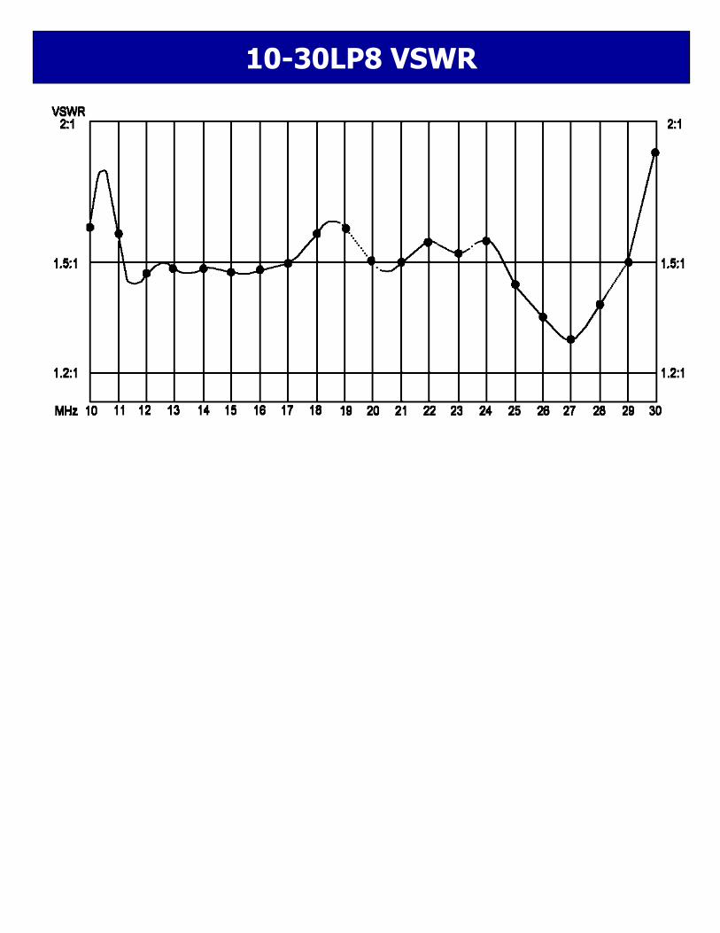
10-30LP8 VSWR