m.2 2242 flash driveeflash.apacerus.com/spec/sata/m.2/sm220-m242_apm2t... · – built-in hardware...
TRANSCRIPT
RoHS Recast Compliant
M.2 2242 Flash Drive
SM220-M242 Product Specifications
July 21, 2017
Version 1.3
Apacer Technology Inc.
1F, No.32, Zhongcheng Rd., Tucheng Dist., New Taipei City, Taiwan, R.O.C
Tel: +886-2-2267-8000 Fax: +886-2-2267-2261
www.apacer.com
M.2 2242 Flash Drive APM2T42SM22xxxGXN-4XTMXX
1 © 2017 Apacer Technology Inc. Rev. 1.3
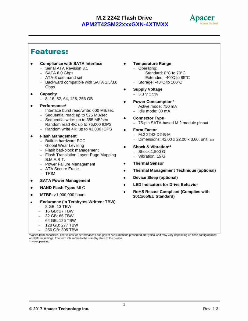
Features:
Compliance with SATA Interface – Serial ATA Revision 3.1 – SATA 6.0 Gbps – ATA-8 command set – Backward compatible with SATA 1.5/3.0
Gbps
Capacity – 8, 16, 32, 64, 128, 256 GB
Performance* – Interface burst read/write: 600 MB/sec – Sequential read: up to 525 MB/sec – Sequential write: up to 355 MB/sec – Random read 4K: up to 76,000 IOPS – Random write 4K: up to 43,000 IOPS
Flash Management – Built-in hardware ECC – Global Wear Leveling – Flash bad-block management – Flash Translation Layer: Page Mapping – S.M.A.R.T. – Power Failure Management – ATA Secure Erase – TRIM
SATA Power Management
NAND Flash Type: MLC
MTBF: >1,000,000 hours
Endurance (in Terabytes Written: TBW) – 8 GB: 13 TBW – 16 GB: 27 TBW – 32 GB: 66 TBW – 64 GB: 126 TBW – 128 GB: 277 TBW – 256 GB: 305 TBW
Temperature Range – Operating:
Standard: 0°C to 70°C Extended: -40°C to 85°C
– Storage: -40°C to 100°C
Supply Voltage
– 3.3 V ± 5%
Power Consumption* – Active mode: 750 mA – Idle mode: 80 mA
Connector Type – 75-pin SATA-based M.2 module pinout
Form Factor – M.2 2242-D2-B-M
– Dimensions: 42.00 x 22.00 x 3.60, unit: ㎜
Shock & Vibration** – Shock:1,500 G – Vibration: 15 G
Thermal Sensor
Thermal Management Technique (optional)
Device Sleep (optional)
LED Indicators for Drive Behavior
RoHS Recast Compliant (Complies with 2011/65/EU Standard)
*Varies from capacities. The values for performances and power consumptions presented are typical and may vary depending on flash configurations or platform settings. The term idle refers to the standby state of the device. **Non-operating
M.2 2242 Flash Drive APM2T42SM22xxxGXN-4XTMXX
2 © 2017 Apacer Technology Inc. Rev. 1.3
Table of Contents
1. General Description .............................................................................. 3
2. Functional Block ................................................................................... 3
3. Pin Assignments .................................................................................... 4
4. Product Specifications.......................................................................... 7
4.1 Capacity ............................................................................................................................................... 7 4.2 Performance ........................................................................................................................................ 7 4.3 Environmental Specifications .............................................................................................................. 8 4.4 Mean Time Between Failures (MTBF) ................................................................................................ 8 4.5 Certification and Compliance .............................................................................................................. 8 4.6 Endurance ........................................................................................................................................... 9 4.7 LED Indicator Behavior........................................................................................................................ 9
5. Flash Management .............................................................................. 10
5.1 Error Correction/Detection ................................................................................................................. 10 5.2 Bad Block Management .................................................................................................................... 10 5.3 Global Wear Leveling ........................................................................................................................ 10 5.4 Power Failure Management .............................................................................................................. 10 5.5 ATA Secure Erase ............................................................................................................................. 10 5.6 TRIM .................................................................................................................................................. 11 5.7 Flash Translation Layer – Page Mapping.......................................................................................... 11 5.8 DEVSLP (DevSleep or DEVSLP) Mode (optional) ............................................................................ 11 5.9 Thermal Sensor ................................................................................................................................. 11 5.10 Thermal Management Technique (optional) ................................................................................... 12 5.11 SATA Power Management .............................................................................................................. 12
6. Software Interface .............................................................................. 13
6.1 Command Set .................................................................................................................................... 13 6.2 S.M.A.R.T. ......................................................................................................................................... 13
7. Electrical Specifications .................................................................... 15
8. Mechanical Specifications ................................................................. 16
8.1 Dimensions ........................................................................................................................................ 16
9. Product Ordering Information ............................................................. 17
9.1 Product Code Designations ............................................................................................................... 17 9.2 Valid Combinations ............................................................................................................................ 18
M.2 2242 Flash Drive APM2T42SM22xxxGXN-4XTMXX
3 © 2017 Apacer Technology Inc. Rev. 1.3
1. General Description
Apacer’s SM220-M242 (M.2 2242) is the next generation modularized Solid State Drive (SSD) with the shape of all new M.2 form factor, with the aim to be the more suitable for mobile and compact computers with standard width at only 22.00 mm. SM220-M242 appears in M.2 2242 mechanical dimensions and is believed to be the leading add-in storage solution for future host computing systems.
The M.2 SSD is designed with SATA-based connector pinouts, providing full compliance with the latest SATA Revision 3.1 interface specifications. Aside from SATA compliance, SM220-M242 delivers exceptional performance and power efficiency. On the other hand, the extreme thin and light form factor makes SM220-M242 the ideal choice for mobile computing systems, which appears to be the trend in near future.
Regarding reliability, SM220-M242 is built with a powerful SATA controller that supports on-the-module ECC as well as efficient wear leveling scheme. Since it is operating under SATA 6.0 Gbps interface, SM220-M242 is provided with Apacer latest S.M.A.R.T. that are primarily oriented for the latest SATA interface SSD, for drive lifetime monitoring and analyzing.
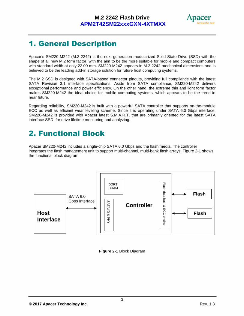
2. Functional Block
Apacer SM220-M242 includes a single-chip SATA 6.0 Gbps and the flash media. The controller integrates the flash management unit to support multi-channel, multi-bank flash arrays. Figure 2-1 shows the functional block diagram.
Figure 2-1 Block Diagram
Controller
SA
TA
I/O &
PH
Y
Fla
sh d
ata
bus &
EC
C e
ngin
e
Flash
Flash
Host Interface
SATA 6.0 Gbps Interface
DDR3 DRAM
M.2 2242 Flash Drive APM2T42SM22xxxGXN-4XTMXX
4 © 2017 Apacer Technology Inc. Rev. 1.3
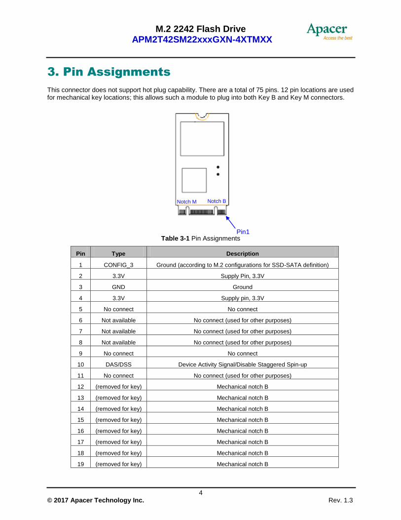
3. Pin Assignments
This connector does not support hot plug capability. There are a total of 75 pins. 12 pin locations are used for mechanical key locations; this allows such a module to plug into both Key B and Key M connectors.
Table 3-1 Pin Assignments
Pin Type Description
1 CONFIG_3 Ground (according to M.2 configurations for SSD-SATA definition)
2 3.3V Supply Pin, 3.3V
3 GND Ground
4 3.3V Supply pin, 3.3V
5 No connect No connect
6 Not available No connect (used for other purposes)
7 Not available No connect (used for other purposes)
8 Not available No connect (used for other purposes)
9 No connect No connect
10 DAS/DSS Device Activity Signal/Disable Staggered Spin-up
11 No connect No connect (used for other purposes)
12 (removed for key) Mechanical notch B
13 (removed for key) Mechanical notch B
14 (removed for key) Mechanical notch B
15 (removed for key) Mechanical notch B
16 (removed for key) Mechanical notch B
17 (removed for key) Mechanical notch B
18 (removed for key) Mechanical notch B
19 (removed for key) Mechanical notch B
Notch B Notch M
Pin1

M.2 2242 Flash Drive APM2T42SM22xxxGXN-4XTMXX
5 © 2017 Apacer Technology Inc. Rev. 1.3
Pin Type Description
20 Not available No connect (used for other purposes)
21 CONFIG_0 Ground (according to M.2 configurations for SSD-SATA definition)
22 Not available No connect (used for other purposes)
23 Not available No connect (used for other purposes)
24 Not available No connect (used for other purposes)
25 Not available No connect (used for other purposes)
26 Not available No connect (used for other purposes)
27 GND Ground
28 Not available No connect (used for other purposes)
29 PERn1 Not used
30 Not available No connect (used for other purposes)
31 PERp1 Not used
32 Not available No connect (used for other purposes)
33 GND Ground
34 Not available No connect (used for other purposes)
35 PETn1 Not used
36 Not available No connect (used for other purposes)
37 PETp1 Not used
38 DEVSLP
Device Sleep, input. If driven high the host is informing the SSD to enter a low power state
39 GND Ground
40 Not available No connect (used for other purposes)
41 SATA-Rx+ Host receiver differential signal pair
42 Not available No connect (used for other purposes)
43 SATA-Rx- Host receiver differential signal pair
44 Not available No connect (used for other purposes)
45 GND Ground
46 Not available No connect (used for other purposes)
47 SATA-Tx- Host transmitter differential pair
48 Not available No connect (used for other purposes)
49 SATA-Tx+ Host transmitter differential pair
50 PERST# Not used
51 GND Ground
52 CLKREQ# Not used
53 REFCLKN Not used
54 PEWAKE# Not used
M.2 2242 Flash Drive APM2T42SM22xxxGXN-4XTMXX
6 © 2017 Apacer Technology Inc. Rev. 1.3
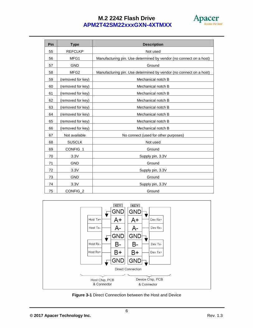
Pin Type Description
55 REFCLKP Not used
56 MFG1 Manufacturing pin. Use determined by vendor (no connect on a host)
57 GND Ground
58 MFG2 Manufacturing pin. Use determined by vendor (no connect on a host)
59 (removed for key) Mechanical notch B
60 (removed for key) Mechanical notch B
61 (removed for key) Mechanical notch B
62 (removed for key) Mechanical notch B
63 (removed for key) Mechanical notch B
64 (removed for key) Mechanical notch B
65 (removed for key) Mechanical notch B
66 (removed for key) Mechanical notch B
67 Not available No connect (used for other purposes)
68 SUSCLK Not used
69 CONFIG_1 Ground
70 3.3V Supply pin, 3.3V
71 GND Ground
72 3.3V Supply pin, 3.3V
73 GND Ground
74 3.3V Supply pin, 3.3V
75 CONFIG_2 Ground
Figure 3-1 Direct Connection between the Host and Device
M.2 2242 Flash Drive APM2T42SM22xxxGXN-4XTMXX
7 © 2017 Apacer Technology Inc. Rev. 1.3
4. Product Specifications
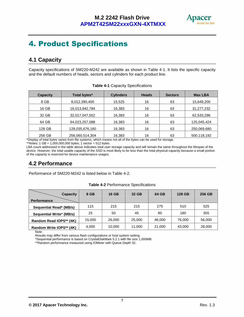
4.1 Capacity
Capacity specifications of SM220-M242 are available as shown in Table 4-1. It lists the specific capacity and the default numbers of heads, sectors and cylinders for each product line.
Table 4-1 Capacity Specifications
Capacity Total bytes* Cylinders Heads Sectors Max LBA
8 GB 8,012,390,400 15,525 16 63 15,649,200
16 GB 16,013,942,784 16,383 16 63 31,277,232
32 GB 32,017,047,552 16,383 16 63 62,533,296
64 GB 64,023,257,088 16,383 16 63 125,045,424
128 GB 128,035,676,160 16,383 16 63 250,069,680
256 GB 256,060,514,304 16,383 16 63 500,118,192 *Display of total bytes varies from file systems, which means not all of the bytes can be used for storage. **Notes: 1 GB = 1,000,000,000 bytes; 1 sector = 512 bytes. LBA count addressed in the table above indicates total user storage capacity and will remain the same throughout the lifespan of the device. However, the total usable capacity of the SSD is most likely to be less than the total physical capacity because a small portion of the capacity is reserved for device maintenance usages.
4.2 Performance
Performance of SM220-M242 is listed below in Table 4-2.
Table 4-2 Performance Specifications
Capacity
Performance
8 GB 16 GB 32 GB 64 GB 128 GB 256 GB
Sequential Read* (MB/s) 115 215 215 275 510 525
Sequential Write* (MB/s) 25 50 45 85 180 355
Random Read IOPS** (4K) 15,000 26,000 25,000 46,000 76,000 56,000
Random Write IOPS** (4K) 4,000 10,000 11,000 21,000 43,000 28,000
Note: Results may differ from various flash configurations or host system setting. *Sequential performance is based on CrystalDiskMark 5.2.1 with file size 1,000MB. **Random performance measured using IOMeter with Queue Depth 32.
M.2 2242 Flash Drive APM2T42SM22xxxGXN-4XTMXX
8 © 2017 Apacer Technology Inc. Rev. 1.3
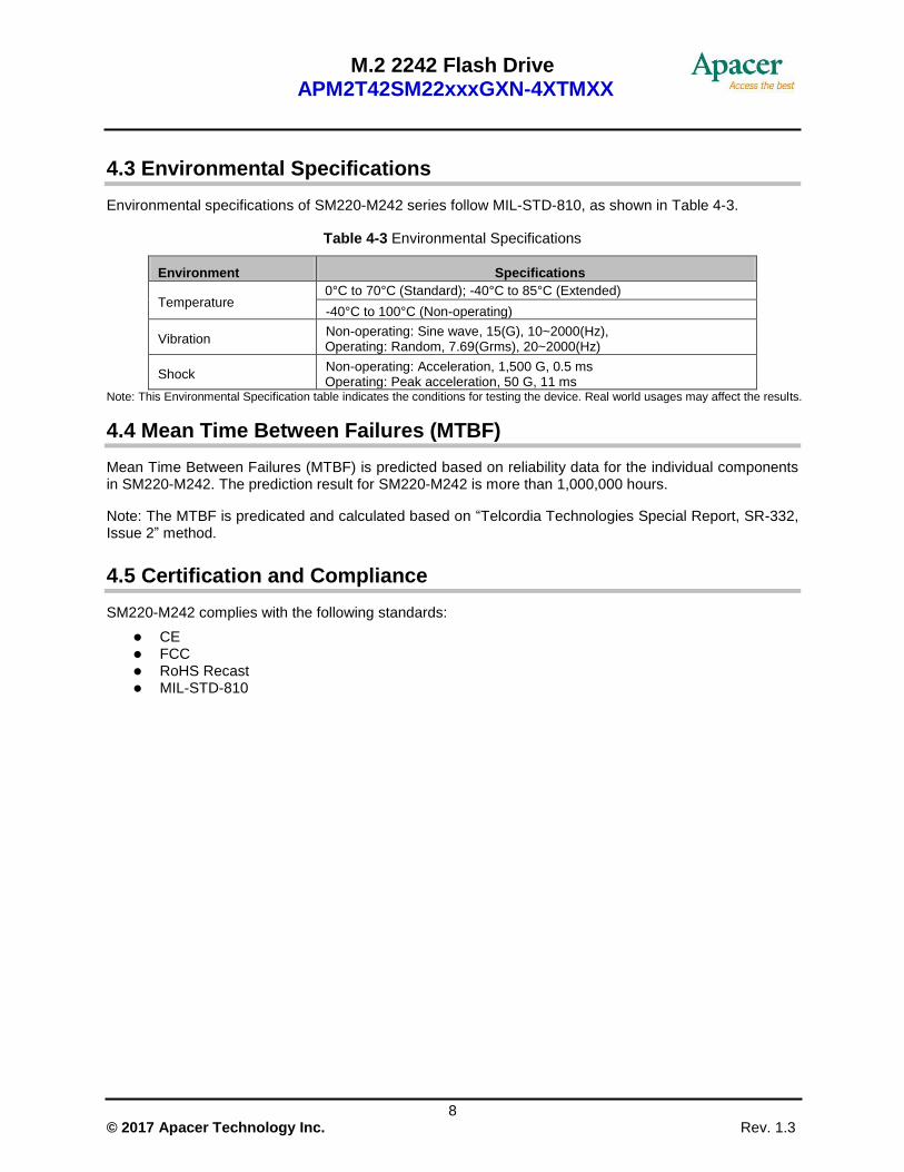
4.3 Environmental Specifications
Environmental specifications of SM220-M242 series follow MIL-STD-810, as shown in Table 4-3.
Table 4-3 Environmental Specifications
Environment Specifications
Temperature 0°C to 70°C (Standard); -40°C to 85°C (Extended)
-40°C to 100°C (Non-operating)
Vibration Non-operating: Sine wave, 15(G), 10~2000(Hz), Operating: Random, 7.69(Grms), 20~2000(Hz)
Shock Non-operating: Acceleration, 1,500 G, 0.5 ms Operating: Peak acceleration, 50 G, 11 ms
Note: This Environmental Specification table indicates the conditions for testing the device. Real world usages may affect the results.
4.4 Mean Time Between Failures (MTBF)
Mean Time Between Failures (MTBF) is predicted based on reliability data for the individual components in SM220-M242. The prediction result for SM220-M242 is more than 1,000,000 hours.
Note: The MTBF is predicated and calculated based on “Telcordia Technologies Special Report, SR-332, Issue 2” method.
4.5 Certification and Compliance
SM220-M242 complies with the following standards:
CE FCC RoHS Recast MIL-STD-810
M.2 2242 Flash Drive APM2T42SM22xxxGXN-4XTMXX
9 © 2017 Apacer Technology Inc. Rev. 1.3
4.6 Endurance
The endurance of a storage device is predicted by TeraBytes Written based on several factors related to usage, such as the amount of data written into the drive, block management conditions, and daily workload for the drive. Thus, key factors, such as Write Amplifications and the number of P/E cycles, can influence the lifespan of the drive.
Capacity TeraBytes Written
8 GB 13
16 GB 27
32 GB 66
64 GB 126
128 GB 277
256 GB 305
Note: The measurement assumes the data written to the SSD for test is under a typical and constant rate. The measurement follows the standard metric: 1 TB (Terabyte) = 1,000 GB. This estimation complies with JEDEC JESD-219, enterprise endurance workload of random data
with payload size distribution.
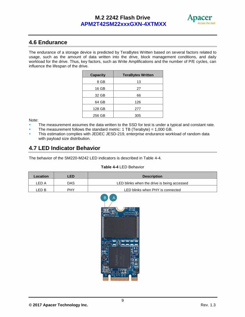
4.7 LED Indicator Behavior
The behavior of the SM220-M242 LED indicators is described in Table 4-4.
Table 4-4 LED Behavior
Location LED Description
LED A DAS LED blinks when the drive is being accessed
LED B PHY LED blinks when PHY is connected
B A
M.2 2242 Flash Drive APM2T42SM22xxxGXN-4XTMXX
10 © 2017 Apacer Technology Inc. Rev. 1.3
5. Flash Management
5.1 Error Correction/Detection
SM220-M242 implements a hardware ECC scheme, based on the BCH algorithm. It can detect and correct up to 40 bits error in 1K bytes.
5.2 Bad Block Management
Current production technology is unable to guarantee total reliability of NAND flash memory array. When a flash memory device leaves factory, it comes with a minimal number of initial bad blocks during production or out-of-factory as there is no currently known technology that produce flash chips free of bad blocks. In addition, bad blocks may develop during program/erase cycles. When host performs program/erase command on a block, bad block may appear in Status Register. Since bad blocks are inevitable, the solution is to keep them in control. Apacer flash devices are programmed with ECC, page mapping technique and S.M.A.R.T to reduce invalidity or error. Once bad blocks are detected, data in those blocks will be transferred to free blocks and error will be corrected by designated algorithms.
5.3 Global Wear Leveling
Flash memory devices differ from Hard Disk Drives (HDDs) in terms of how blocks are utilized. For HDDs, when a change is made to stored data, like erase or update, the controller mechanism on HDDs will perform overwrites on blocks. Unlike HDDs, flash blocks cannot be overwritten and each P/E cycle wears down the lifespan of blocks gradually. Repeatedly program/erase cycles performed on the same memory cells will eventually cause some blocks to age faster than others. This would bring flash storages to their end of service term sooner. Global wear leveling is an important mechanism that levels out the wearing of all blocks so that the wearing-down of all blocks can be almost evenly distributed. This will increase the lifespan of SSDs.
5.4 Power Failure Management
Power Failure Management plays a crucial role when experiencing unstable power supply. Power disruption may occur when users are storing data into the SSD. In this urgent situation, the controller would run multiple write-to-flash cycles to store the metadata for later block rebuilding. This urgent operation requires about several milliseconds to get it done. At the next power up, the firmware will perform a status tracking to retrieve the mapping table and resume previously programmed NAND blocks to check if there is any incompleteness of transmission.
5.5 ATA Secure Erase
ATA Secure Erase is an ATA disk purging command currently embedded in most of the storage drives. Defined in ATA specifications, (ATA) Secure Erase is part of Security Feature Set that allows storage drives to erase all user data areas. The erase process usually runs on the firmware level as most of the ATA-based storage media currently in the market are built-in with this command. ATA Secure Erase can securely wipe out the user data in the drive and protects it from malicious attack.
M.2 2242 Flash Drive APM2T42SM22xxxGXN-4XTMXX
11 © 2017 Apacer Technology Inc. Rev. 1.3
5.6 TRIM
TRIM is a SATA command that helps improve the read/write performance and efficiency of solid-state drives (SSD). The command enables the host operating system to inform SSD controller which blocks contain invalid data, mostly because of the erase commands from host. The invalid will be discarded permanently and the SSD will retain more space for itself.
5.7 Flash Translation Layer – Page Mapping
Page mapping is an advanced flash management technology whose essence lies in the ability to gather data, distribute the data into flash pages automatically, and then schedule the data to be evenly written. Page-level mapping uses one page as the unit of mapping. The most important characteristic is that each logical page can be mapped to any physical page on the flash memory device. This mapping algorithm allows different sizes of data to be written to a block as if the data is written to a data pool and it does not need to take extra operations to process a write command. Thus, page mapping is adopted to increase random access speed and improve SSD lifespan, reduce block erase frequency, and achieve optimized performance and lifespan.
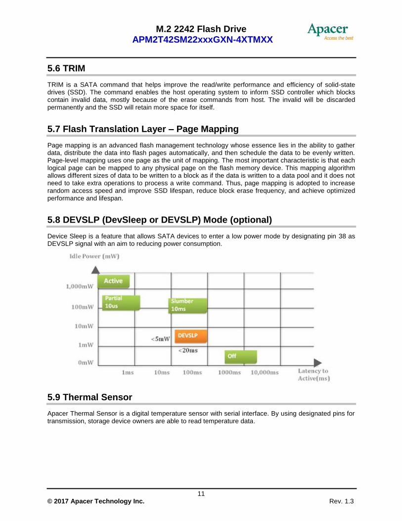
5.8 DEVSLP (DevSleep or DEVSLP) Mode (optional)
Device Sleep is a feature that allows SATA devices to enter a low power mode by designating pin 38 as DEVSLP signal with an aim to reducing power consumption.
5.9 Thermal Sensor
Apacer Thermal Sensor is a digital temperature sensor with serial interface. By using designated pins for transmission, storage device owners are able to read temperature data.

M.2 2242 Flash Drive APM2T42SM22xxxGXN-4XTMXX
12 © 2017 Apacer Technology Inc. Rev. 1.3
5.10 Thermal Management Technique (optional)
Thermal management technique can monitor the temperature of the SSD equipped with a built-in thermal sensor via S.M.A.R.T. commands. This method can ensure the temperature of the device stays within temperature limits by drive throttling, i.e. reducing the speed of the drive when the device temperature reaches the threshold level, so as to prevent overheating, guarantee data reliability, and prolong product lifespan. When the temperature exceeds the maximum threshold level, thermal throttling will be triggered to reduce performance to prevent hardware components from being damaged. Performance is only permitted to drop to the extent necessary for recovering a stable temperature to cool down the device’s temperature. Once the temperature decreases step by step to the minimum threshold value, transfer speeds will rise back to its optimum performance level.
5.11 SATA Power Management
By complying with SATA 6.0 Gb/s specifications, the SSD supports the following SATA power saving modes:
ACTIVE: PHY ready, full power, Tx & Rx operational
PARTIAL: Reduces power, resumes in under 10 µs (microseconds)
SLUMBER: Reduces power, resumes in under 10 ms (milliseconds)
HIPM: Host-Initiated Power Management
DIPM: Device-Initiated Power Management
AUTO-SLUMBER: Automatic transition from partial to slumber.
Device Sleep (DevSleep or DEVSLP): PHY powered down; power consumption ≦ 5 mW; host
assertion time ≦ 10 ms; exit timeout from this state ≦ 20 ms (unless specified otherwise in SATA
Identify Device Log).
Note: 1. The behaviors of power management features would depend on host/device settings. 2. Device Sleep mode is optional, depending on product ordering selections.
M.2 2242 Flash Drive APM2T42SM22xxxGXN-4XTMXX
13 © 2017 Apacer Technology Inc. Rev. 1.3
6. Software Interface
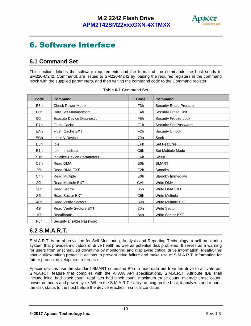
6.1 Command Set
This section defines the software requirements and the format of the commands the host sends to SM220-M242. Commands are issued to SM220-M242 by loading the required registers in the command block with the supplied parameters, and then writing the command code to the Command register.
Table 6-1 Command Set
Code Command Code Command
E5h Check Power Mode F3h Security Erase Prepare
06h Data Set Management F4h Security Erase Unit
90h Execute Device Diagnostic F5h Security Freeze Lock
E7h Flush Cache F1h Security Set Password
EAh Flush Cache EXT F2h Security Unlock
ECh Identify Device 70h Seek
E3h Idle EFh Set Features
E1h Idle Immediate C6h Set Multiple Mode
91h Initialize Device Parameters E6h Sleep
C8h Read DMA B0h SMART
25h Read DMA EXT E2h Standby
C4h Read Multiple E0h Standby Immediate
29h Read Multiple EXT CAh Write DMA
20h Read Sector 35h Write DMA EXT
24h Read Sector EXT C5h Write Multiple
40h Read Verify Sectors 39h Write Multiple EXT
42h Read Verify Sectors EXT 30h Write Sector
10h Recalibrate 34h Write Sector EXT
F6h Security Disable Password
6.2 S.M.A.R.T.
S.M.A.R.T. is an abbreviation for Self-Monitoring, Analysis and Reporting Technology, a self-monitoring system that provides indicators of drive health as well as potential disk problems. It serves as a warning for users from unscheduled downtime by monitoring and displaying critical drive information. Ideally, this should allow taking proactive actions to prevent drive failure and make use of S.M.A.R.T. information for future product development reference.
Apacer devices use the standard SMART command B0h to read data out from the drive to activate our S.M.A.R.T. feature that complies with the ATA/ATAPI specifications. S.M.A.R.T. Attribute IDs shall include initial bad block count, total later bad block count, maximum erase count, average erase count, power on hours and power cycle. When the S.M.A.R.T. Utility running on the host, it analyzes and reports the disk status to the host before the device reaches in critical condition.
M.2 2242 Flash Drive APM2T42SM22xxxGXN-4XTMXX
14 © 2017 Apacer Technology Inc. Rev. 1.3
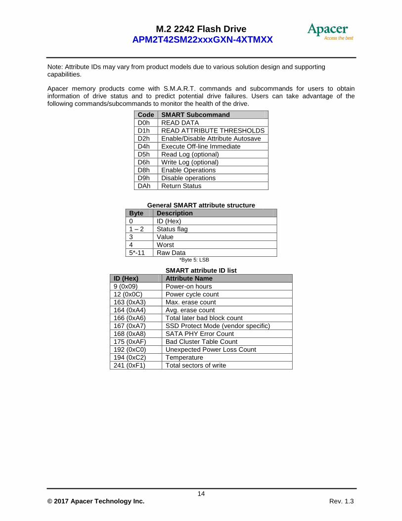
Note: Attribute IDs may vary from product models due to various solution design and supporting capabilities.
Apacer memory products come with S.M.A.R.T. commands and subcommands for users to obtain information of drive status and to predict potential drive failures. Users can take advantage of the following commands/subcommands to monitor the health of the drive.
Code SMART Subcommand
D0h READ DATA
D1h READ ATTRIBUTE THRESHOLDS
D2h Enable/Disable Attribute Autosave
D4h Execute Off-line Immediate
D5h Read Log (optional)
D6h Write Log (optional)
D8h Enable Operations
D9h Disable operations
DAh Return Status
General SMART attribute structure
Byte Description
0 ID (Hex)
1 – 2 Status flag
3 Value
4 Worst
5*-11 Raw Data *Byte 5: LSB
SMART attribute ID list
ID (Hex) Attribute Name
9 (0x09) Power-on hours
12 (0x0C) Power cycle count
163 (0xA3) Max. erase count
164 (0xA4) Avg. erase count
166 (0xA6) Total later bad block count
167 (0xA7) SSD Protect Mode (vendor specific)
168 (0xA8) SATA PHY Error Count
175 (0xAF) Bad Cluster Table Count
192 (0xC0) Unexpected Power Loss Count
194 (0xC2) Temperature
241 (0xF1) Total sectors of write

M.2 2242 Flash Drive APM2T42SM22xxxGXN-4XTMXX
15 © 2017 Apacer Technology Inc. Rev. 1.3
7. Electrical Specifications
Table 7-1 Operating Range
Item Range
Supply Voltage 3.3V ± 5% (3.135-3.465V)
Table 7-2 Power Consumption
Capacity
Mode
8 GB 16 GB 32 GB 64 GB 128 GB 256 GB
Active (mA) 215 240 240 305 430 750
Idle (mA) 80 80 80 80 75 75
Note: *All values are typical and may vary depending on flash configurations or host system settings. **Active power is an average power measurement performed using CrystalDiskMark with 128KB sequential read/write transfers.

M.2 2242 Flash Drive APM2T42SM22xxxGXN-4XTMXX
16 © 2017 Apacer Technology Inc. Rev. 1.3
8. Mechanical Specifications
8.1 Dimensions

M.2 2242 Flash Drive APM2T42SM22xxxGXN-4XTMXX
17 © 2017 Apacer Technology Inc. Rev. 1.3
9. Product Ordering Information
9.1 Product Code Designations
A P M2 T42 SM22 x x x G XN – 4X TMX X
Flash Type
M.2
Apacer Product Code
Form Factor
Solution Version
Capacity 008G = 8GB 016G = 16GB 032G = 32GB 064G = 64GB 128G = 128GB 256G = 256GB
Version Control
Add-On Value TN: Thermal Sensor FN: Thermal Sensor + DEVSLP
Operating Temp. Range Blank: Standard temperature W: Extended temperature

M.2 2242 Flash Drive APM2T42SM22xxxGXN-4XTMXX
18 © 2017 Apacer Technology Inc. Rev. 1.3
9.2 Valid Combinations
9.2.1 Without DEVSLP
Capacity Standard Temperature Extended Temperature
8GB APM2T42SM22008GTN-4ETM APM2T42SM22008GTN-4ETMW
16GB APM2T42SM22016GTN-4ETM APM2T42SM22016GTN-4ETMW
32GB APM2T42SM22032GTN-4ETM APM2T42SM22032GTN-4ETMW
64GB APM2T42SM22064GTN-4ETM APM2T42SM22064GTN-4ETMW
128GB APM2T42SM22128GTN-4ETMG APM2T42SM22128GTN-4ETMGW
256GB APM2T42SM22256GTN-4ETMG APM2T42SM22256GTN-4ETMGW
9.2.2 With DEVSLP (optional)
Capacity Standard Temperature Extended Temperature
8GB APM2T42SM22008GFN-4FTM APM2T42SM22008GFN-4FTMW
16GB APM2T42SM22016GFN-4FTM APM2T42SM22016GFN-4FTMW
32GB APM2T42SM22032GFN-4FTM APM2T42SM22032GFN-4FTMW
64GB APM2T42SM22064GFN-4FTM APM2T42SM22064GFN-4FTMW
128GB APM2T42SM22128GFN-4FTMG APM2T42SM22128GFN-4FTMGW
256GB APM2T42SM22256GFN-4FTMG APM2T42SM22256GFN-4FTMGW Note: Valid combinations are those products in mass production or will be in mass production. Consult your Apacer sales representative to confirm availability of valid combinations and to determine availability of new combinations.

M.2 2242 Flash Drive APM2T42SM22xxxGXN-4XTMXX
19 © 2017 Apacer Technology Inc. Rev. 1.3
Revision History
Revision Date Description Remark
1.0 3/20/2017 Official release
1.1 3/29/2017
- Changed the 9.2.1 title from Default to Without DEVSLP
- Removed product photo from the cover page
1.2 5/4/2017
- Added product photo on the cover page
- Added 4.6 Endurance
- Updated vibration and shock specifications
- Updated the product photo at 4.7 LED Indicator Behavior
1.3 7/20/2017 Added a figure to 3. Pin Assignments
M.2 2242 Flash Drive APM2T42SM22xxxGXN-4XTMXX
20 © 2017 Apacer Technology Inc. Rev. 1.3
Global Presence
Taiwan (Headquarters)
Apacer Technology Inc.
Apacer Technology Inc. 1F., No.32, Zhongcheng Rd., Tucheng Dist., New Taipei City 236, Taiwan R.O.C. Tel: 886-2-2267-8000 Fax: 886-2-2267-2261 [email protected]
U.S.A.
Apacer Memory America, Inc.
46732 Lakeview Blvd., Fremont, CA 94538 Tel: 1-408-518-8699 Fax: 1-510-249-9551 [email protected]
Japan
Apacer Technology Corp.
5F, Matsura Bldg., Shiba, Minato-Ku Tokyo, 105-0014, Japan Tel: 81-3-5419-2668 Fax: 81-3-5419-0018 [email protected]
Europe
Apacer Technology B.V.
Science Park Eindhoven 5051 5692 EB Son, The Netherlands Tel: 31-40-267-0000 Fax: 31-40-290-0686 [email protected]
China
Apacer Electronic (Shanghai) Co., Ltd
Room D, 22/FL, No.2, Lane 600, JieyunPlaza, Tianshan RD, Shanghai, 200051, China Tel: 86-21-6228-9939 Fax: 86-21-6228-9936 [email protected]
India
Apacer Technologies Pvt Ltd,
Unit No.201, “Brigade Corner”, 7th
Block Jayanagar, Yediyur Circle, Bangalore – 560082, India Tel: 91-80-4152-9061 Fax: 91-80-4170-0215 [email protected]