m1/m2/m3/m4/m5/m6/m7-*-*-40 - yuken by ala … series motors m1/m2/m3/m4/m5/m6/m7-*-*-40 notice of...
TRANSCRIPT

M Series Motors M1/M2/M3/M4/M5/M6/M7-*-*-40
Notice of Model Change
We are pleased to announce that the M series motors will be remodeled to comply with the Top Runner criteria that come into force in April 2015, and their design number will be changed from 30 to 40. ■Description of the Change In the context of worldwide efforts against global warming, many countries have set minimum requirements for energy consumption efficiency and introduced legislation to mandate the use of higher efficiency electric motors. In Japan, the Top Runner criteria will regulate the efficiency of induction motors from April 2015, and our M series motors will be remodeled to comply with the criteria. ■Major Changes ・The efficiency class of these motors will be changed to IE3 (premium), and their overall specifications will be improved. ・The terminal box is located on the upper side (standard), but the left or right side is also selectable as before. ・The overall motor bodies will be bigger, and their masses will increase by a range of 2 to 31 kg (110 to 1142% rate of increase in mass). ・CE mark is available for these motors, including standard products.
■Model Number Designation
Note 1) For the following models, either the left or right side terminal box location is selectable (the upper side (standard)
terminal box is not available). M1-0.75/M4-18.5/M5-18.5
2) 400 V specifications are also available. For details, contact us separately.
M1 -1.5 -R -40 Series Number Motor Capacity Terminal Box Location Note 1) Design Number
M1 [For AR16/AR22/A10/A16/A22] 0.75: 0.75 kW×4P, 1.5: 1.5 kW×4P,2.2: 2.2 kW×4P, 3.7: 3.7 kW×4P
M2 [For A37 (excluding 04E)] 3.7: 3.7 kW×4P, 5.5: 5.5 kW×4P, 7.5: 7.5 kW×4P
M3 [For AR16/AR22/A10/A16/A22] 5.5: 5.5 kW×4P, 7.5: 7.5 kW×4P
M4 [For A37 (excluding 04E)]
M5 [For A37(04E)/A56]
5.5: 5.5 kW×4P, 7.5: 7.5 kW×4P, 11: 11 kW×4P, 15: 15 kW×4P,
18.5: 18.5 kW×4P M6 [For A3H16] 5.5: 5.5 kW×4P, 7.5: 7.5 kW×4P
M7 [For A3H37] 7.5: 7.5 kW×4P, 11: 11 kW×4P 15: 15 kW×4P
[When viewed from the pump
mounting surface]
None: Upper side (Standard)
R: Right side L: Left side
40
No.1
April 2015
Public Relations GroupSales Planning Section
Sales Planning Department Hamamatsucho Seiwa Bdg., 4-8,
Shibadaimon 1-chome, Minato-ku, Tokyo 105-0012, Japan
Tel: +81-3-3432-2113 Fax: +81-3-3436-2344
NO. 15 01E Public Relations Group
Sales Planning Section Sales Planning Department
Hamamatsucho Seiwa Bdg., 4-8, Shibadaimon 1-chome, Minato-ku,
Tokyo 105-0012, Japan Tel: +81-3-3432-2113 Fax: +81-3-3436-2344

■Specification Comparison between Old and New Models
Note 1) Values in parentheses are added when there are differences in specifications between the old and new models A value before parentheses: value of a new model with the design number 40, a value in parentheses: value of an old model with the design number 30.
2) New models with the design number 40 have larger starting current values than those of old models with the design number 30. This point should be taken into consideration when designing power distribution.
3) With improved slip control, new models with the design number 40 have faster rotational speed values than those of old models with the design number 30. This point should be taken into consideration because “the output may increase,” or “the flow rate may become too high,” depending on operating conditions.
■Mounting Interchangeability between Old and New Models
Output × Number of Poes
Voltage-Frequency V Hz
Rated CurrentA
Starting CurrentA
Rotational Speed r/min
Insulation Class
0.75 kW×4P 200-50 200-60 220-60
3.8 (3.9) 3.4
3.4 (3.3)
27.3 (20.6) 23.8 (19.7) 26.2 (21.7)
1440 (1410) 1730 (1690) 1745 (1710)
F (B)
1.5 kW×4P 200-50 200-60 220-60
6.8 (6.3) 6.4 (6.0) 6.0 (5.5)
46.6 (34.4) 41.0 (32.3) 45.1 (35.5)
1445 (1410) 1740 (1700) 1750 (1720)
F (B)
2.2 kW×4P 200-50 200-60 220-60
10.6 (9.7) 9.4 (8.9) 9.2 (8.4)
96.0 (64.0) 81.0 (58.2) 89.1 (64.0)
1460 (1410) 1755 (1700) 1765 (1720)
F (B)
3.7 kW×4P 200-50 200-60 220-60
15.6 14.6
13.8 (13.6)
134 (108) 118 (96)
130 (106)
1460 (1410) 1755 (1700) 1765 (1720)
F (B)
5.5 kW×4P 200-50 200-60 220-60
23.4 (23.0) 21.4 (21.0) 20.6 (20.0)
200 (150) 166 (130) 183 (143)
1465 (1430) 1760 (1730) 1765 (1740)
F (B)
7.5 kW×4P 200-50 200-60 220-60
30.8 (31.2) 28.6 (28.4) 27.4 (26.8)
264 (218) 218 (192) 240 (211)
1460 (1435) 1755 (1730) 1765 (1740)
F
11 kW×4P 200-50 200-60 220-60
46.0 (43.5) 42.0 (41.4) 40.0 (38.4)
365 (297) 302 (250) 332 (275)
1475 (1440) 1770 (1730) 1775 (1740)
F (B)
15 kW×4P 200-50 200-60 220-60
58.8 (59.0) 55.6 (55.4) 52.0 (51.0)
484 (460) 408 (368) 449 (405)
1470 (1430) 1760 (1730) 1770 (1740)
F (B)
200-50 74.0 (71.0) 668 (468) 1475 (1455) F
No.2
Interchangeability Model Description
Interchangeable M1, M2, M3-5.5, M4-5.5/11/15/18.5
M5-5.5/11/15/18.5, M6, M7
Not interchangeable
M3-7.5, M4-7.5, M5-7.5 Pump mounting portion is the same between the old and new models. The distance (dimension IL) between the pump mounting location and the motor mounting center is different.

M1-075
Motor Dimensions (mm) Model
Number A B C D E F G IL J KL L M N P PD PL T W Z M1-1.5 154.5 ― 90 202 70 62.5 10 118.5 40 167 273 176 149 70 ― 0 27 40 12 10
M1-2.2 178 239.5 100 202 80 70 12 136 40 167 314 200 168 93.5 37.5 0 27 46 14 12
M1-3.7 M2-3.7
186 271.5 112 243 95 70 12 143.5 40 186.5 329.5 220 168 95 47 0 27 44 14 12
M2-5.5 210.5 323 132 285 108 70 15 163.5 50 263 374 260 175 85 56.5 45.5 49 50 14 12
M2-7.5 261 323 132 285 108 70 15 163.5 50 263 424.5 260 175 85 56.5 45.5 49 50 14 12
M1-0.75
M1-1.5/2.2/3.7 M2-3.7/5.5/7.5
No.3
Note) Note)
Note) For M1-1.5, no eyebolt is provided.
Motor Dimensions (mm) Model
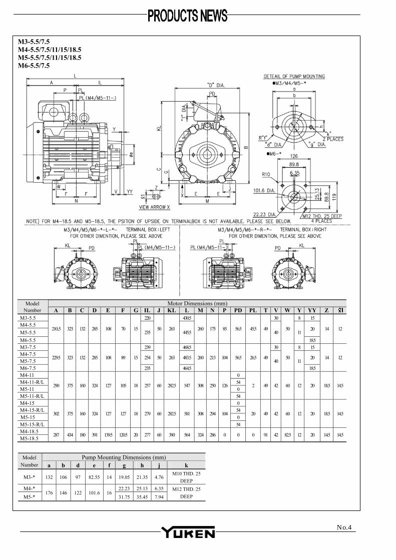
Number A B C D E F G IL J KL L M N P PD PL T V W Y YY Z M3-5.5 220 430.5 30 8 15 M4-5.5 M5-5.5
20
M6-5.5
210..5 323 132 285 108 70 15 235
50 263 445.5
260 175 85 56.5 45.5 49 40
50 11
18.5
14 12
M3-7.5 239 468.5 30 8 15 M4-7.5 M5-7.5
254 483.5 20
M6-7.5
229.5 323 132 285 108 89 15
235
50 263
464.5
260 213 104 56.5 26.5 49 40
50 11
18.5
14 12
M4-11 0 M4-11-R/L 54 M5-11 0 M5-11-R/L
290 375 160 324 127 105 18 257 60 282.5 547 308 250 126
54
2 49 42 60 12 20 18.5 14.5
M4-15 0 M4-15-R/L 54 M5-15 0 M5-15-R/L
302 375 160 324 127 127 18 279 60 282.5 581 308 294 104
54
20 49 42 60 12 20 18.5 14.5
M4-18.5 M5-18.5
287 434 180 391 139.5 120.5 20 277 60 390 564 324 286 0 0 0 91 42 82.5 12 20 14.5 14.5
Pump Mounting Dimensions (mm) Model
Number a b d e f g h j k
M3-* 132 106 97 82.55 14 19.05 21.35 4.76 M10 THD. 25
DEEP M4-* 22.23 25.13 6.35
M5-* 176 146 122 101.6 16
31.75 35.45 7.94 M12 THD. 25
DEEP
M3-5.5/7.5 M4-5.5/7.5/11/15/18.5 M5-5.5/7.5/11/15/18.5 M6-5.5/7.5
No.4

Motor Dimensions (mm) Model Number A C D E F G IL J KL L M N P PD PL W Z
M7-7.5 229.5 132 285 108 89 15 235 50 263 464.5 260 213 104 56.5 26.5 50 14 12
M7-11 0
M7-11-R/L 290 105 257 547 250 126
54 2
M7-15 0
M7-15-R/L 302
160 324 127
127
18
279
60 282.5
581
308
294 104 54
20
60 18.5 14.5
M7-7.5/11/15
No.5

■Dimensional Comparison between Old and New Models Since the terminal box position of 30 design was R equivalency, the new 40 design assumes terminal box positon "R" was compared with the old 30 design. [Model M1-0.75] [Models M1-1.5 to 3.7/M2]
No.6
Dimensions (mm) Model Number
A J KL L P T WMass (kg)
Old M1-0.75-30 130 33 146 237.5 27.5 22 22 14.3 New M1-0.75-R-40 153.5 35 157 261 77.5 27 30 17.9
Note) Dimensions not listed in the above table are the same between old and new models. See the dimensional drawings.
Dimensions (mm)
Model Number A B D N KL W L P PD T PL
Mass (kg)
Old M1-1.5-30 143 231 198 150 147 261.5 0 0 20 New M1-1.5-R-40 154.5 ― 202 149 167 273 70 ― 22 Old M1-2.2-30 157.5 241 198 147 293.5 0 0 26 New M1-2.2-R-40 178 239.5 202 167 314 93.5 37.5 30 Old M1-3.7-30 261 214 154 46 0 0 29 New M1-3.7-R-40 271.5 243 186.5 44 95 47 41 Old M2-3.7-30 261 214 154 46 0 0 29 New M2-3.7-R-40 271.5 243 186.5 44 95 47 41 Old M2-5.5-30 303 252 189 0 0 35 0 45 New M2-5.5-R-40 323 285 263 85 56.5 49 45.5 62 Old M2-7.5-30 233.5 303 252 189 412 0 0 35 0 51 New M2-7.5-R-40 261 323 285 263 424.5 85 56.5 49 45.5 75 Note 1) Dimensions not listed in the above table are the same between old and new models. See the
dimensional drawings. 2) For M1-1.5-*-40, no eyebolt is provided.
Note 2) Note 2)

[Models M3/M4/M5/M6/M7]
No.7
Note) Dimensions not listed in the above table are the same between old and new models. See the dimensional drawings.
Dimensions (mm) Model Number
A B D F IL KL L N P PD PL TMass(kg)
M3-5.5-30 47 M4-5.5-30 M5-5.5-30 50 O
ld
M6-5.5-30
303 252 189 0 0 0 35
48 M3-5.5-R-40 63 M4-5.5-R-40 65 M5-5.5-R-40 N
ew
M6-5.5-R-40
323 285 263 85 56.5 45.5 4968
M3-7.5-30 220 53 M4-7.5-30 M5-7.5-30
248.5 70 235 175 56
M6-7.5-30 53
Old
M7-7.5-30
303 252
189
0 0 0 35
54.5M3-7.5-R-40 239 74 M4-7.5-R-40 M5-7.5-R-40
229.5 89 254 213
M6-7.5-R-40 76 N
ew
M7-7.5-R-40
323 285
263
104 56.5 26.5 49
77.5M4-11-30 M5-11-30 O
ld
M7-11-30 302 351 304 257.5 559 22 0 0 52 85
M4-11-R-40 M5-11-R-40 N
ew
M7-11-R-40 290 375 324 282.5 547 126 56.5 2 49 114
M4-15-30 M5-15-30 O
ld
M7-15-30 280 351 304 257.5 559 0 0 0 52 100
M4-15-R-40 M5-15-R-40 N
ew
M7-15-R-40 302 375 324 282.5 581 104 56.5 20 49 131
M4-18.5-30
Old
M5-18.5-30 320 431 382 335 597 60 175
M4-18.5-R-40
New
M5-18.5-R-40 287 434 391 390 564 91 193

■Timing of Release Scheduled to be released in April 2015. ■Reference No.15-06E Low noise type hydraulic power units YA Packs. .
No.8
Contact
International Sales Department 4-4-34, Kamitsuchidana-Naka, Ayase, Kanagawa Pref. 252-1113, Japan Phone: +81-467-77-3111 Fax: +81-467-77-3115 e-mail: [email protected] Internet: www.yuken.co.jp

137
AMシリーズ
電動機
M シリーズ電動機
Piston Pumps
“M” Series Electric Motors
M Series Motor
This is a test......。
● Easily mounting of the pump. ● Low noise and vibration. ● It allows you to reduce the floor space, because it is compact. ● It is also safe, because the shaft is not exposed.
■ Specifications
★1. If you need a wattage other than the ones listed, please contact your Yuken service representative.★2. If you need a voltage other than the ones listed, please contact your Yuken service representative.
Voltage★2-Hertz
V Hz
0.75 kW × 4P
A
A
r/min
kg
Type
M1−0.75−30200−50200−60220−60
3.93.43.3
20.619.721.7
141016901710
B 14.3
6.36.05.5
34.432.335.5
141017001720
B 201.5 kW × 4PM1−1.5 −30200−50200−60220−60
9.78.98.4
64.058.264.0
141017001720
B 262.2 kW × 4PM1−2.2 −30200−50200−60220−60
15.614.613.6
10896.0106
141017001720
B 293.7 kW × 4PM1−3.7 −30M2−3.7 −30
200−50200−60220−60
23.021.020.0
150130143
143017301740
B
4547
50
48
5.5 kW × 4PM4−5.5 −30M5−5.5 −30M6−5.5 −30
M2−5.5 −30M3−5.5 −30 200−50
200−60220−60
5153
56
5354.5
31.228.426.8
218192211
143517301740
F7.5 kW × 4PM4−7.5 −30M5−7.5 −30M6−7.5 −30M7−7.5 −30
M2−7.5 −30M3−7.5 −30
200−50200−60220−60
43.541.438.4
297250275
144017301740
B 8511 kW × 4PM4−11 −30M5−11 −30M7−11 −30
200−50200−60220−60
59.055.451.0
460368405
143017301740
B 10015 kW × 4PM4−15 −30M5−15 −30M7−15 −30
200−50200−60220−60
71.068.063.0
468393432
145517501760
B 17518.5 kW × 4PM4−18.5−30M5−18.5−30
200−50200−60220−60
●
●IMPORTANT NOTE!*Must be keep indoors.*Operates between -20 to 40°C.*There must be less than 100%
relative humiditiy.*Altitude must be 1000m or less.*Keep away from flamable gases.
■ Applicable Pump(s)
M1−※−30M3−※−30
Single Piston Pump Double Piston Pump Piston and Vane Pump Combo
Piston Pump Vane Pump ★1
AR16/AR22/A10/A16/A22 A1616/A1622/A2222 A16R1/A22R1 PV2R1
M2−※−30M4−※−30 A37(04Eを除く) − − PV2R2
M5−※−30 A37(04E)/A56 A1637/A2237/A1656/A2256 A37R1/A56R1 −
M6−※−30 A3H16 − − −
M7−※−30 A3H37 − − −
★1. Certian Vane pumps can be mounted, but the hardware needed is differenct, please contact for more information.★2. This pump requires different hardware.
★2

138 Mシリーズ電動機
106.54.785
146.16.375
φ82.55
φ101.6
4-M12ねじ 深23
4-M10ねじ 深17
φ19.05
φ22.225
21.5
106.5
25.3
146.1
M1-0.75/1.5/2.2/3.7M2-3.7/5.5/7.5
● M1-※
● M2-※
■ モデル番号の構成 ■ 付 属 品
★1. ポンプ取付用六角ボルトの締付トルクは、下記によってください。 ボルトサイズM10:28.3~31.3 Nm ボルトサイズM12:49.8~55 Nm★2. 平座金の種類はみがき丸です。
CI
B
φT
G
Z
W
N
F F
J
M
EE
KLD A IL
L
P
1
ポンプ取付部詳細
モデル番 号
付 属 品
六角ボルト★1 平座金★2
サイズ 個数 サイズ 個数カップリング(1個)
M1-※
M2-※
M3-※
M4-※
M5-※
M6-※
M7-※
M10×25L
M12×30L
M10×25L
M12×30L
M12×30L
M12×30L
M12×30L
2
2
2
2
2
4
4
10
12
10
12
12
12
12
2
2
2
2
2
4
4
-
-
1490-PK313763-5
1490-PK313761-9(5.5, 7.5 kW)
1490-PK313762-7(11~18.5 kW)
1490-PK313759-3(5.5, 7.5 kW)
1490-PK313760-1(11~18.5 kW)
1490-PK313761-9(5.5, 7.5 kW)
1490-PK313939-1
モデル番号電 動 機容量・極数
電動機寸法 mm
A IL B C D E F G I J M N KL W Z ℓ1 L P T
M1-0.75 0.75 kW×4P 130 107.5 -★1 80 170 62.5 50 4.5 165 33 165 130 146 22 10 18 237.5 27.5 22
M1-1.5 1.5 kW×4P 143 118.5 41 90 198 70 62.5 10 190 40 176 150 147 40 10 12 261.5 - 27
M1-2.2 2.2 kW×4P 157.5 136 41 100 198 80 70 12 200 40 200 168 147 46 12 14 293.5 - 27
M1-3.7M2-3.7
3.7 kW×4P 186 143.5 41 112 214 95 70 12 220 40 220 168 154 46 12 14 329.5 - 27
M2-5.5 5.5 kW×4P 210.5163.5 46 132 252 108 70 15 257 50 260 175 189 50 12 14
374- 35
M2-7.5 7.5 kW×4P 233.5 397
★1. M1-0.75には、アイボルトは設けていません。
M1 -1.5 -30シリーズ番号 電動機容量 デザイン番号
M1AR16/AR22A10/A16/A22
0.75:0.75 kW×4P 1.5:1.5 kW×4P 2.2:2.2 kW×4P 3.7:3.7 kW×4P
30
M2[A37(04Eを除く)]
3.7:3.7 kW×4P 5.5:5.5 kW×4P 7.5:7.5 kW×4P
30
M3AR16/AR22A10/A16/A22
5.5:5.5 kW×4P 7.5:7.5 kW×4P 30
M4[A37(04Eを除く)]
5.5:5.5 kW×4P 7.5:7.5 kW×4P 11:11 kW×4P 15:15 kW×4P18.5:18.5 kW×4P
30
M5[A37(04E)/A56]
5.5:5.5 kW×4P 7.5:7.5 kW×4P 11:11 kW×4P 15:15 kW×4P18.5:18.5 kW×4P
30
M6(A3H16)
5.5:5.5 kW×4P 7.5:7.5 kW×4P 30
M7(A3H37)
7.5:7.5 kW×4P 11:11 kW×4P 15:15 kW×4P
30
( )
( )

139
AM
シリーズ
電動機
Mシリーズ電動機
ピストンポンプ
89.8
119
89.8
R10 6.35
25.13
126
4-M12 ねじ深 25 φ22.23
KLD
φT
J
E
ba
E
C
IB
G
Z
W
NM
FF
X
YY
2-"k"R"f"
φe
A ILL
P
Y
j
h
1
φd
φ101.6
φg
M3-5.5/7.5M4-5.5/7.5/11/15/18.5M5-5.5/7.5/11/15/18.5M6-5.5/7.5
YYYXTPLℓ1ZWKLNMJIGFEDCBILA
M3-5.5
5.5 kW×4PM4-5.5M5-5.5
M6-5.5
M3-7.5
7.5 kW×4PM4-7.5M5-7.5
M6-7.5
11 kW×4PM4-11M5-11
15 kW×4P
18.5 kW×4P
M4-15M5-15
M4-18.5M5-18.5
210.5
233.5
229.5
302
280
320
220
220
235
235
257
279
277
46
46
46
46
60
132
132
160
160
180
252
252
304
304
382
108
108
127
127
139.5
70
70
105
127
120.5
15
15
18
18
20
257
257
305
305
371
50
50
60
60
60
260
260
308
308
324
175
175
250
294
286
189
189
257.5
257.5
335
50
50
60
60
82.5
12
12
14.5
14.5
φ14.5
14
14
18.5
18.5
-
430.5
453.5
445.5
468.5
464.5
559
559
597
-
-
22
-
-
35
35
52
52
60
30
30
40
40
42
42
42
8
8
11
11
12
12
12
15
15
20
18.5
20
18.5
20
20
20
モデル番 号
電 動 機容量・極数
電動機寸法 mm
89 213
モデル番 号
M3-※
M4-※
M5-※
a
132
176
b
106
146
d
97
122
e
82.55
101.6
f
14
16
g
19.05
22.23
h
21.35
25.13
j
4.76
6.35
31.75 35.45 7.94
k
M10ねじ 深25
M12ねじ 深25
ポンプ取付部寸法 mm
ポンプ取付部詳細
● M3/M4/M5-※
● M6-※

140 Mシリーズ電動機
φT
J
EE
Z
ℓ1 W
FF
M N
42
20
AD ILL
P
φ127
C
I46
G
13
114.5φ25.4
φ2146.35
114.5
28.3
4-M12ねじ深24
KL
M7-7.5/11/15
■ ポンプの取付け
ポンプの取付けは、下記の手順にて行ってください。
● M1/M2形の場合
1. 電動機軸のキー溝とポンプ軸のキーの位置を合わせ、電動機軸の穴にポンプ軸を挿入し、ポンプを取付ける。
2. 平座金を取付けた2本の六角ボルトにより、ポンプを固定する。締付トルクは138ページの付属品の項を参照のこと。
● M3~M7形の場合
1. ポンプ軸に円筒ハブを取付け、右図に示す“A”寸法の位置に位置決め後、六角穴付止ねじ(2本)で固定する(締付トルク:4.8~7.0 Nm)。
2. ポンプ軸の円筒ハブにエレメントを取付ける。3. 電動機軸のインサートとポンプ側のエレメントがかみ合うようにして、ポンプを電動機に組付ける。
4. 平座金を取付けた2本の六角ボルト(M6/M7形のみ4本)により、ポンプを固定する。締付トルクは138ページの付属品の項を参照のこと。
注)円形ハブとインサート、および、電動機軸とインサートは、あらかじめ位置調整を行った後、★印を付した六角穴付ボルトで固定してあります。六角穴付ボルトは緩めないでください。
★
★
エレメント
円筒ハブ 電動機軸
インサート
ポンプ軸電動機軸
六角穴付止ねじ(2箇所) 六角穴二面幅 3
円筒ハブ
ポンプ軸端 円筒ハブ端面
A
ポンプ取付部詳細
モデル番号 A mm
M3-※ 0±0.5
M4-5.5/7.5 1±0.5
M4-11/15/18.5 3±0.5
M5-5.5/7.5 -2±0.5 ★1
M5-11/15/18.5 0±0.5
M6-5.5/7.5 8.5±0.5
M7-※ 0.5±0.5
★1. M5-5.5/7.5のみ、円筒ハブ端面からポンプ軸が出っ張ります。
モデル番 号
電 動 機容量・極数
電動機寸法 mm
A IL C D E F G I J M N KL W Z ℓ1 L P T
M7-7.5 7.5 kW×4P 229.5 235 132 252 108 89 15 257 50 260 213 189 50 12 14 464.5 - 35
M7-11 11 kW×4P 302 257160 304 127
10518 305 60 308
250257.5 60 14.5 18.5 559
2252
M7-15 15 kW×4P 280 279 127 294 -

141
AM
シリーズ
電動機
Mシリーズ電動機
ピストンポンプ
旧製品との互換性について
■ M1/M2/M3/M4/M5、20デザイン→30デザイン
● 主な変更内容安定した供給体制確保のためモデルチェンジを実施。これに伴い、電流値、外形寸法、質量が異なりますが、互換性はあります。
● 仕様の比較新旧で定格電流、始動電流および回転数に若干の増減はありますが、実用上の支障はありません。
【新旧電動機仕様の比較】
出力 × 極数電圧-周波数V Hz
定格電流A
始動電流A
回転速度r/min
絶縁等級
0.75 kW × 4P200-50200-60220-60
3.93.43.3
20.6 (19)19.7 (17)21.7 (19)
1410 (1400)1690 (1680)1710 (1700)
E
6.3 (7.2)6.0 (6.5)5.5 (6.3)
34.4 (40)32.3 (36)35.5 (40)
1410 (1420)17001720
B (E)
9.7 (10.0)8.9
8.4 (8.6)
64.0 (58)58.2 (52)64.0 (57)
1410 (1430)1700 (1720)1720 (1730)
E
15.6 (16.0)14.6 (14.6)13.6 (14.0)
108 (110)96.0 (95)106 (105)
1410 (1430)1700 (1720)1720 (1730)
E
23.021.020.0
150 (130)130 (113)143 (125)
1430 (1440)17301740
B
1.5 kW × 4P200-50200-60220-60
2.2 kW × 4P200-50200-60220-60
3.7 kW × 4P200-50200-60220-60
5.5 kW × 4P200-50200-60220-60
31.2 (31.0)28.4 (29.0)26.8 (27.0)
218 (190)192 (168)211 (185)
1435 (1440)17301740
F (B)7.5 kW × 4P200-50200-60220-60
43.5 (42.0)41.4 (40.0)38.4 (38.0)
297 (280)250 (245)275 (270)
1440 (1450)1730
1740 (1750)B11 kW × 4P
200-50200-60220-60
59.0 (54.0)55.4 (54.0)51.0 (50.0)
460 (420)368 (364)405 (400)
1430 (1450)1730
1740 (1750)B15 kW × 4P
200-50200-60220-60
71.0 (68.0)68.0 (66.0)63.0 (60.0)
468 (500)393 (436)432 (480)
1455 (1450)1750 (1740)1760 (1750)
B18.5 kW × 4P200-50200-60220-60
注)新旧で仕様が異なる部分を( )で併記してあります。 ( )外:新30デザイン、( )内:旧20デザインの仕様を示します。
● 取付の互換性◯有、取付けに関する基本寸法(142、143ページで★印を付した寸法)に変更はありません。

142 Mシリーズ電動機
【M1/M2形 新旧外形寸法の比較】
旧:20デザイン
W
N
F★ F★J
M
E★E★
KLD
C★
I
G
φT
AIL★L
P
Z
1
2-吊り金具
新:30デザイン
C★
IB
φT
G
Z
W
N
F★ F★J
M
E★E★
KLD A IL★
L
P
1
取付穴詳細
注)上図で★印を付した寸法は、新旧で同一ですので、138ページの外形寸法図をご参照ください。
124
130
142.5
143
160.5
157.5
171
186
217
210.5
217
233.5
160
170
178
198
195
198
219
214
276
252
276
252
10
4.5
10
10
13
12
14
12
16
15
16
15
160
165
179
190
197.5
200
221.5
220
270
257
270
257
34
33
35
40
45
40
45
40
50
50
50
50
155
165
170
176
195
200
224
220
250
260
250
260
135
130
155
150
175
168
175
168
175
175
175
175
126
146
136
147
150
147
161
154
217
189
217
189
50.5
22
51
40
56.5
46
52.5
46
56
50
56
50
10
18
10
12
12
14
12
14
12
14
12
14
25
10
16
10
25
12
25
12
25
12
25
12
21
27.5
36.5
-
45.5
-
53
-
33.5
-
33.5
-
22
22
22
27
22
27
22
27
34
35
34
35
12.0
14.3
16.0
20.0
20.0
26.0
29.0
29.0
48
45
54
51
旧 M1-0.75-20
新 M1-0.75-30
旧 M1-1.5 -20
新 M1-1.5 -30
旧 M1-2.2 -20
新 M1-2.2 -30
旧 M1-3.7 -20
M2-3.7 -20
新 M1-3.7 -30
M2-3.7 -30
旧 M2-5.5 -20
新 M2-5.5 -30
旧 M2-7.5 -20
新 M2-7.5 -30
231.5
237.5
261
261.5
296.5
293.5
314.5
329.5
380.5
374
380.5
397
-
-
-
41
-
41
-
41
41.5
46
41.5
46
モデル番号質量kgℓ1 L P TKL W ZJ M NG IA B
寸 法 mm
D

143
AM
シリーズ
電動機
Mシリーズ電動機
ピストンポンプ
【M3/M4/M5形 新旧外形寸法の比較】
KLD
φT
J
E★E★
C★
IB
G
Z
W
NM
F★F★X★YY★
φe★
A IL★L
P
Y★
1
モデル番号質量kgℓ1 L P TKL W ZJ M NG IA B
寸 法 mm
D
M3-5.5 -20
M4-5.5 -20M5-5.5 -20
M3-5.5 -30
M4-5.5 -30M5-5.5 -30
M3-7.5 -20
M4-7.5 -20M5-7.5 -20
M3-7.5 -30
M4-7.5 -30M5-7.5 -30
M4-11 -20M5-11 -20
M4-11 -30M5-11 -30
M4-15 -20M5-15 -20
M4-15 -30M5-15 -30
M4-18.5-20M5-18.5-20
M4-18.5-30M5-18.5-30
旧
新
旧
新
旧
新
旧
新
旧
新
217
210.5
217
233.5
270
302
292
280
311
320
42
46
42
46
51
46
51
46
60
272
252
272
252
320
304
320
304
366
382
16
15
16
15
20
18
20
18
22
20
270
257
270
257
318
305
318
305
367
371
50
50
60
60
70
60
250
260
250
260
315
308
315
308
350
324
175
175
262
250
306
294
294
286
215
189
215
189
240
257.5
240
257.5
320
335
56
50
56
50
61
60
63
60
65
82.5
25
12
25
12
φ15
14.5
φ15
14.5
φ15
φ14.5
12
14
12
14
-
18.5
-
18.5
-
-
437
452
430.5
445.5
437
452
453.5
468.5
527
559
571
559
588
597
33.5
0
33.5
0
0
22
0
0
34
35
34
35
34
52
34
52
49
60
51
54
47
50
57
60
53
56
108
85
123
100
173
175
注)上図で★印を付した寸法は、新旧で同一ですので、139ページの外形寸法図をご参照ください。