m07 10 g_kegel_ff_topologies_for_is_5.12.07
TRANSCRIPT

© 2007 Fieldbus Foundation
Dr.-Ing. Gunther KegelCEO Pepperl+Fuchs GmbH, Mannheim
Member of the Fieldbus Foundation Board of DirectorsChairman of the FF European Executive Advisory Council
Foundation Fieldbus Topologies for Intrinsically Safe (IS) Installations

2© 2007 Fieldbus Foundation
Content
1. Necessity of topology elements
2. Preferred general fieldbus topology
3. IS fieldbus topologies
4. Vision
5. DART technology
3© 2007 Fieldbus Foundation
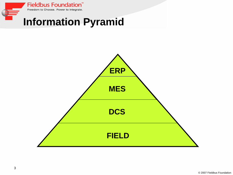
Information Pyramid
ERP
MES
DCS
FIELD

4© 2007 Fieldbus Foundation
Automation Pyramid
Sensors und Actuators
Interfaces
PLC
DCS
HMI
Information Q
uantity
Information Q
uality
5© 2007 Fieldbus Foundation
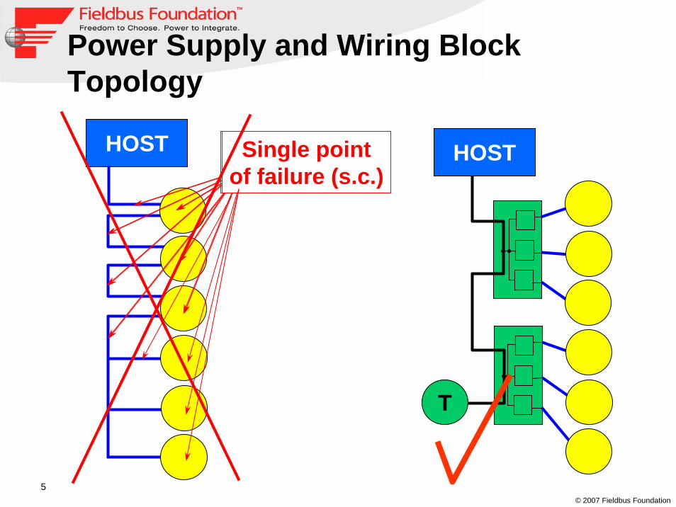
Power Supply and Wiring Block Topology
HOST Single pointof failure (o.c.)
Single pointof failure (s.c.)
HOST
T

6© 2007 Fieldbus Foundation
...Fieldbusex-ipower supply
Typical IS fieldbus topology in 2000

7© 2007 Fieldbus Foundation
Fieldbusbarrier FieldbusbarrierFieldbusbarrier
Termination
Typical IS fieldbus topology in 2004
Fieldbuspowersupply
ex-ispurs
8© 2007 Fieldbus Foundation
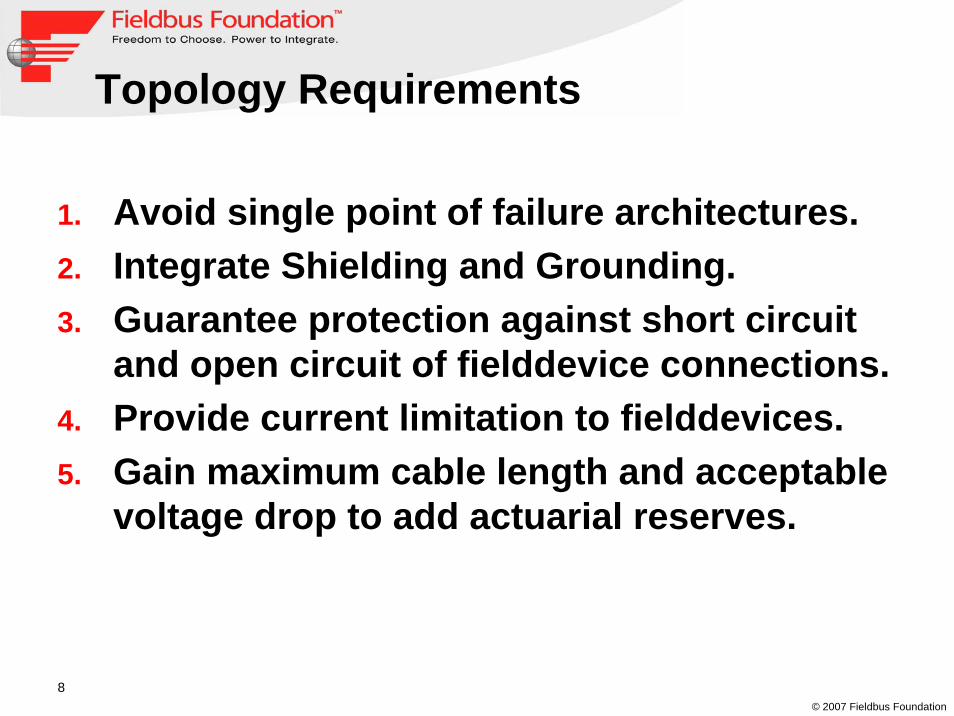
Topology Requirements
1. Avoid single point of failure architectures.2. Integrate Shielding and Grounding.3. Guarantee protection against short circuit
and open circuit of fielddevice connections.4. Provide current limitation to fielddevices.5. Gain maximum cable length and acceptable
voltage drop to add actuarial reserves.
9© 2007 Fieldbus Foundation
Fieldbus topology for IS installationsIn general the same arguments apply for ISinstallations in regards of grounding; shielding; protection etc.In addition the topology has to provide the ISisolation between safe areas (e.g. control room) and hazardous areas (e.g. field).As fieldbus devices are low power devices anyhow, IS is a very appropriate method for fieldbusinstallations in hazardous areas.Today two different IS installation concepts for fieldbus are existing:
“True intrinsic safety“-Concept“High Power Trunk“-Concept

10© 2007 Fieldbus Foundation
“True Intrinsic Safety“-Concept
H1 T
24VTrunk:Ex-i FISCO Gas Group IIC…15 V / 100 mAEx-i FISCO Gas Group IIB….15 V / 200 mA
FISCO Fieldbus Powersupply
Spur:Ex-i FISCO Gas Group IIC .. >10 V / 30 mA
ActiveJunction Box

11© 2007 Fieldbus Foundation
“High Power Trunk“-Concept
H1 T
24V Trunk:Ex-e ……………. < 31 V / 500 mA
Powersupply
Spur:Ex-i FISCO Gas Group IIC .. >10 V / 30 mA
FieldbusBarrier

12© 2007 Fieldbus Foundation
Characteristics
TrunkProtection
SpurProtection
IsolationTrunkSpec.
Power SupplyRedundancy
True Intrinsic Safety Ex-i FISCO Power
Supply17 V
200 mA1) NO
High Power Trunk Ex-e FISCO
Power Supply+FieldbusBarrier
31 V500 mA2) YES
1) Values are for gas group IIB only.2) Other devices with (e.g. 25 V / 360 mA) are also available

13© 2007 Fieldbus Foundation
VISION
“True Intrinsic Safety”-Concept and “High Power Trunk”-Concept are both widely accepted and have to be seen as prooventechnology.What about a “True Intrinsically Safe High Power Trunk”-Concept?In other words: Can we achieve high power on an intrinsically safe trunk?

14© 2007 Fieldbus Foundation
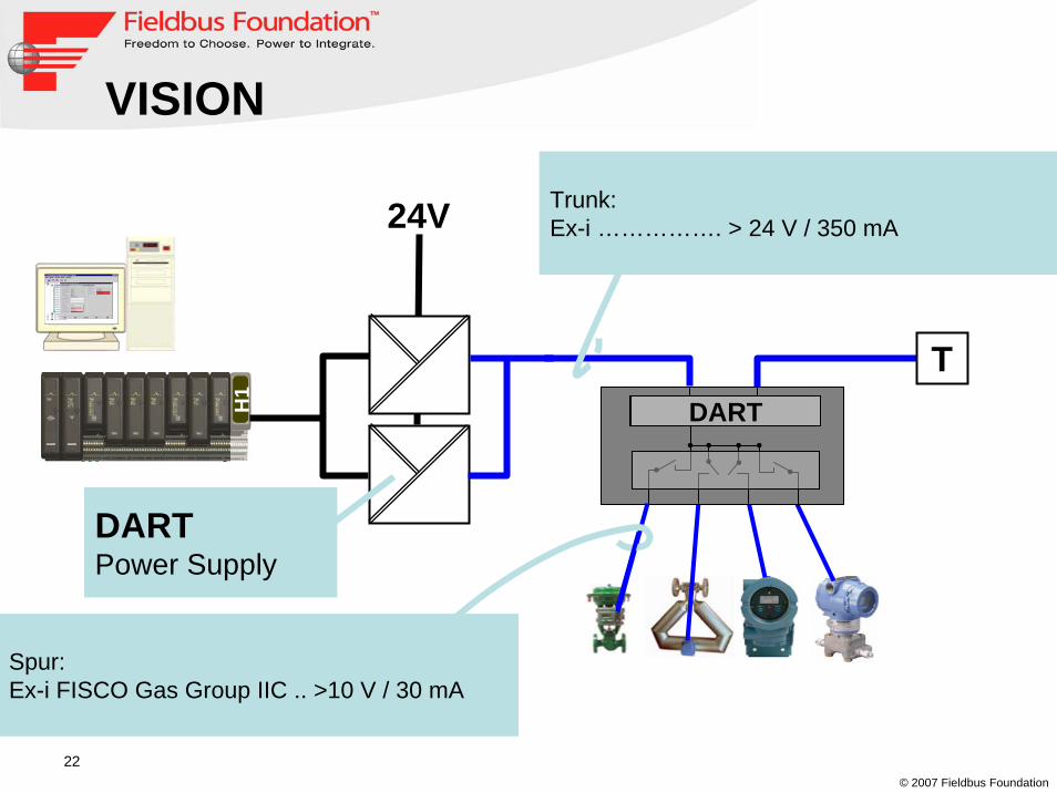
VISION
H1
T
24V
Spur:Ex-i FISCO Gas Group IIC .. >10 V / 30 mA
Trunk:Ex-i ……………. > 24 V / 350 mA

15© 2007 Fieldbus Foundation
Advantages
Single Ex-i harzadous area protection concept, no Ex-e wiring.High Power Trunk offers more cable length through accepting bigger voltage drops along the trunk cable.Simplified Active Junction Box (compared to Fieldbusbarrier).Spurs remain FISCO protected.

16© 2007 Fieldbus Foundation
24 V / 350 mAIntrinsically Safe !?

17© 2007 Fieldbus Foundation
Principle of Intrinsic Safety
The energy in an intrinsically safe system is limited to a value that is not capable of causing ignition in normal operation and fault condition in the surrounding hazardous atmospheres by sparks (opening, closing, short circuit, short circuit to earth)
“ i ”
U
R L
C

18© 2007 Fieldbus Foundation
Principle of Intrinsic Safety
The classic protection method is to limit voltage, current, power, inductance and capacity in an intrinsically safe system to a constant value.
-> The results are documented in “Ignition curves”

19© 2007 Fieldbus Foundation
Physics of an arc
Rectangular source, U= 25V, I= 500mA, 1000m cable, cable break at 500m
0
5
10
15
20
25
30
0 10 20 30 40 50t [ µs]
U [V
]
0
0.1
0.2
0.3
0.4
0.5
0.6
I [A
]
criticalphase
initialphase
Funken -strom IF
Funken -spannung UFSpark voltage
Spark current

20© 2007 Fieldbus Foundation
DART
DART is a new intrinsically safe concept developed and approved by Physikalische
Technische Bundesanstalt (PTB) in Braunschweig and Pepperl+Fuchs Mannheim.
Dynamic Arc Recognition &Termination
The principle of DART is the detection of the development of an arc and the fast shut down of
power source and/or sink.
21© 2007 Fieldbus Foundation
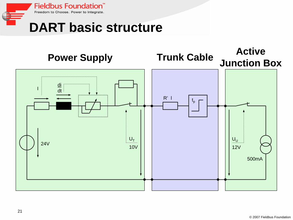
DART basic structure
24V
Ididt
UT
10V
tp
UU
12V
500mA
Power Supply Trunk Cable ActiveJunction Box
R’ l
22© 2007 Fieldbus Foundation
VISION
H1
T
24V
Spur:Ex-i FISCO Gas Group IIC .. >10 V / 30 mA
Trunk:Ex-i ……………. > 24 V / 350 mA
DARTPower Supply
DART

23© 2007 Fieldbus Foundation
Conclusion
TrunkProtection
SpurProtection
IsolationTrunkSpec.
Power Supply
Redundancy
True Intrinsic Safety
Ex-i FISCO Power Supply
17 V 200 mA1) NO
High Power Trunk
Ex-e FISCO
Power Supply+FieldbusBarrier
31 V500 mA2) YES
DART Ex-i FISCOPowerSupply
24 V350 mA YES
24© 2007 Fieldbus Foundation
Want to know more about DART and fieldbus?
Visit the Interkama 2008 in Hannover!