m z s flores , p a s autreto , s b legoas and d s galvao … · 2009-10-22 · graphene to...
TRANSCRIPT
Graphene to Graphane: A Theoretical Study
M Z S Flores1, P A S Autreto1, S B Legoas2 and D S Galvao1
1Instituto de Fısica “Gleb Wataghin”, Universidade Estadual de Campinas,Unicamp, C.P. 6165, 13083-970, Campinas, Sao Paulo, Brazil2Centro de Ciencias e Tecnologia, Universidade Federal de Roraima, 69304-000, BoaVista, Roraima, Brazil
E-mail: [email protected]
Abstract. Graphane is a two-dimensional system consisting of a single layer of fullysaturated (sp3 hybridization) carbon atoms. In an ideal graphane structure C-H bondsexhibit an alternating pattern (up and down with relation to the plane defined by thecarbon atoms). In this work we have investigated using ab initio and reactive moleculardynamics simulations the role of H frustration (breaking the H atoms up and downalternating pattern) in graphane-like structures. Our results show that significantpercentage of uncorrelated H frustrated domains are formed in the early stages ofthe hydrogenation process leading to membrane shrinkage and extensive membranecorrugations. These results also suggest that large domains of perfect graphane-likestructures are unlikely to be formed, H frustrated domains are always present.
PACS numbers: 81.05.Uw, 81.05.Zx, 71.15.Mb
Submitted to: Nanotechnology
arX
iv:0
910.
4304
v1 [
cond
-mat
.mtr
l-sc
i] 2
2 O
ct 2
009
Graphene to Graphane: A Theoretical Study 2
1. Introduction
Carbon-based materials have been intensely investigated in recent decades. However,
in spite of the enormous amount of theoretical and experimental works, the discovery
of new structures seems endless, colossal carbon tubes [1] and graphene [2] being recent
examples.
Graphene is one of the most important subject in materials science today [2, 3, 4].
It is a two-dimensional structure of sp2 carbon atoms with very unusual and interesting
electronic and mechanical properties.
It has been theoretically predicted that a related structure, called graphane [5],
could exist in a stable form. Graphane consists of a single layer structure with fully
saturated (sp3 hybridization) carbon atoms with C-H bonds in an alternating pattern
(up and down with relation to the plane defined by the carbon atoms). Its two most
stable conformations are the so-called chair-like (H atoms alternating on both sides of
the plane) and boat-like (H atoms alternating in pairs) [5] (figure 1). A third member of
these two-dimensional planar carbon structures, called graphyne [6, 7, 8], has also been
predicted to exist but up to now only molecular fragments have been synthesized [7].
Indirect experimental evidences of graphane-like structures have been reported
[9, 10]. More recently, in a series of very elegant experiments, Elias et al. [11]
demonstrated the existence of graphane formation from graphene membrane through
its hydrogenation. They also demonstrated that this process is reversible. These
fundamental discoveries open new and important perspectives to the use of graphene-
based devices since the electronic gap values in graphanes could be controlled by the
degree of hydrogenation [11, 12].
The Elias et al. experiments consisted in exposing graphene membranes to H+
from cold plasma. The H incorporation into the membranes results in altering the C
sp2 hybridizations to sp3 ones. The experiments were also done with the membranes
over SiO2 substrates (only one membrane side exposed to H+) and produced a material
with different properties. Detailed studies of hydrogen atoms on graphene have been
recently reported [13, 14, 15, 16, 17, 18, 19, 20].
This paper is organized as follows: in Sec. 2 we describe the used methodology.
The results and discussions are presented in Sec. 3, followed by the summary and our
conclusions in Sec. 4.
2. Methodology
We have used different methods to carry out our investigations. Initially, we performed
ab initio quantum calculations in order to optimize the geometry of graphane-
like structures. For comparison purposes, graphene structures were also calculated.
Secondly, we used classical reactive bond-order approach in order to investigate the
effects of hydrogenation on geometrical structures for a number of graphene membrane
models. Finally, molecular dynamics (MD) simulations were used to address the

Graphene to Graphane: A Theoretical Study 3
dynamics of hydrogen incorporation into graphene membranes.
We have carried out ab initio total energy calculations in the framework of the
density functional theory (DFT), as implemented in the DMol3 code [21]. Exchange
and correlation terms were treated within the generalized gradient (GGA) functional
by Perdew, Burke, and Ernzerhof [22]. Core electrons were treated in a non-relativistic
all electron implementation of the potential. A double numerical quality basis set with
polarization function (DNP) were considered, with a real space cutoff of 3.7 A. The
tolerances of energy, gradient, and displacement convergence were 0.00027 eV, 0.054
eV/A and 0.005 A, respectively.
We investigated fully and partially hydrogenated infinite (periodic boundary
condition - PBC) graphene structures, which requires the use of slab supercells. Sofo,
Chaudhari, and Baker [5] in their graphane work considered compact (interacting layers)
structures. Here, in order to mimic the experimental conditions [11], we have considered
isolated (non-interacting) layers. For all cases considered here, the c axis was fixed at
20 A(large enough to prevent interactions among different layers), and the remaining
free parameters were fully optimized (figure 1). Internal atomic positions were free
to vary in all the geometry minimization calculations. The total energy results as
function of the unit cell volumes were fitted following the well known Murnaghan
procedure [23]. We have also considered small finite structures (figure 2) with hydrogen
passivated borders. In order to investigate larger structures, where ab initio quantum
calculations becomes computationally prohibitive, we used ReaxFF binding energy bond
order (BEBO) method [24, 25, 26].
ReaxFF is similar to standard non-reactive force fields, like MM3 [27], where the
system energy is divided into partial energy contributions associated with, amongst
others, valence angle bending, bond stretching, as well as, non-bonded van der Waals and
Coulomb interactions [24, 25]. However, one main difference is that ReaxFF can handle
bond formation and dissociation (making/breaking bonds) as a function of bond order
values. ReaxFF was parameterized against DFT calculations, the average deviation
between the predicted ReaxFF heat of formation values and the experimental ones are
of 2.8 and 2.9 Kcal/mol for non-conjugated and conjugated systems, respectively [25].
ReaxFF is a reactive force field developed by Adri van Duin, William Goddard III and
co-workers for use in MD simulations. This method allows the simulation of many types
of chemical reactions. Similarly to the procedures we adopted in DFT calculations
we have considered both finite and infinite (PBC) structures. We have carried out
geometry optimizations using gradient conjugated techniques (convergence condition,
gradient values less than 10−3).
The dynamics of hydrogen incorporation on graphene layers was studied under
different conditions of temperature (300K, 500K and 650K) and hydrogen atmospheres
(number of H atoms up to twice the number of carbon ones). We considered H
distributed over one and both sides of the graphene layers (infinite membranes with 11
× 11 unit cells). For each temperature different H velocity distributions were used. In
order to speed up the hydrogen incorporation in the first 500 fs of the simulations, after

Graphene to Graphane: A Theoretical Study 4
each MD run of 10 fs, the hydrogen velocities were recalculated and the H atoms directed
towards the graphene membrane. Typical total MD runs were of 50 ps, timesteps of 0.5
fs, and using a Berendsen thermostat [28].
3. Results and Discussions
We started carrying out DMol3 calculations for the infinite (PBC) structures shown in
figure 1. The results are displayed in table 1. The chair-like graphane (figure 1(c)) is
more stable than the boat-like (figure 1(b)) by 0.03 Ha (∼ 0.82 eV). The G-boat presents
two non equivalent carbon-carbon distances due to the existence of two different C-H
alignments. Although the C-C distances in graphane are much longer (8 %) than the
ones present in graphene, its cell parameter is just slightly larger (3 %) than the latter
due to out-of-plane topology. We have also considered the case of the minimum unit cell
with H atoms parallelly aligned (just one side of the membrane). Our results show that
this system is unstable with the tendency of H2 recombination and/or C-C breaking
bonds. The results are in good agreement with previous work [5, 13, 14, 29] and with
the available experimental data [2, 11].
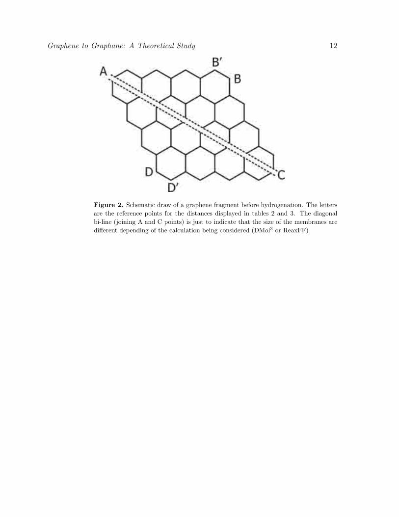
One important aspect to be investigated is how different hydrogenation patterns
affect the geometry of the graphene membranes. One practical way to do this is
to measure some representative distances, as the ones indicated in figure 2 and the
second neighbor C-C distances (which would correspond to the lattice parameter in
ideal crystalline structures).
If we consider that H atoms are randomly incorporated during plasma exposure
[2], there is a significant probability for the existence of H frustration (figure 3), which
is a configuration where the sequence of alternating up and down H atoms is broken
(frustrated) (see movie01 [30]). This is similar to spin frustration in magnetic materials
[31]. Two different H frustration configurations are possible (figure 4), one with parallel
H atoms (Frust-1) and the other with missing H atoms (Frust-0).
In figure 3(a) we show a domain of up and down H atoms. It is expected that
after the first (up or down) H incorporation, the next favorable site is its first inverse
neighbor (down or up), and so on. If the system is large enough uncorrelated domains
might be formed (figure 3(b)). As the H coverage is continued it could occur that it is
no longer possible the alternating sequence of up and down H atoms (figure 3(c)).
We have investigated finite fragments with and without H frustrations. We
analyzed the associated geometrical changes (figure 2) in order to determine whether the
structures expand or contract with relation to an equivalent ideal graphane structure.
We have carried out DMol3 (table 2) and ReaxFF (for larger fragments) calculations
(table 3, figure 2). As we can see from these tables, DMol3 and ReaxFF show similar
and consistent results. The H frustration increases out of plane distortions which induce
in-plane geometrical shrinkage. This effect is amplified when first-neighbor H atoms are
parallelly aligned (figure 4).
The representative distances indicated in (figure 2) (table 2 and table 3) provide a

Graphene to Graphane: A Theoretical Study 5
general view of the geometric changes produced by the different hydrogenation patterns.
A more local information can be obtained averaging the C-C second-neighbor distances
(which would correspond to the lattice parameter for ideal structures). As can be
seen from the tables and from (figure 5) the H frustration systematically reduce these
distances to smaller values in comparison to ideal graphane structures. For particular
configurations these distances can be even smaller than the corresponding graphene
values ((see also supplementary materials [30]).
Finally, we investigated the dynamics of H incorporation using MD simulations.
We have carried out MD calculations to investigate the formation of graphane-like
through hydrogen reactions with the C carbons of the graphene layers. We have
used infinite (using periodic boundary conditions) graphene structures. In figure 6
we show representative snapshots from the early and final stages of a simulation at
500 K (see movie02 [30]). The results show that significant percentage of uncorrelated
H frustrated domains are formed in the early stages of the hydrogenation processes
leading to membrane shrinkages and extensive membrane corrugations. These results
also suggest that large domains of perfect graphane-like structures are unlikely to
be formed, H frustrated domains are always present. The number of these domains
seems to be sensitive to small variations of temperatures and H gas densities. We run
annealing cycle simulations to analyze the stability of these domains once formed. Our
results show that H frustrated domain are very stable, high temperatures are needed to
reverse (dehydrogenation processes) graphane-like structures to their original graphene
configurations.
4. Summary and Conclusions
We have performed geometry optimizations and molecular dynamics simulations using
ab initio DMol3 and classical reactive bond order ReaxFF, respectively, for the
hydrogenation process of graphene leading to graphane-like structures. Graphane is
a two-dimensional system consisting of a single planar layer of fully saturated (sp3
hybridization) carbon atoms with H atoms attached to them in an alternating pattern
(up and down with relation to the plane defined by the carbon atoms).
Our results show that H frustration are very likely to occur. H frustration is
a configuration where the sequence of alternating up and down H atoms is broken
(frustrated). The H frustration increase out of plane distortions (in relation to ideal
graphane structures) which induces in-plane dimensional shrinkage. The net result is a
decrease of the carbon-carbon distances in relation to the ideal graphane values. This
effect is amplified when first neighbor H atoms are parallelly aligned. The results show
that significant percentage of uncorrelated H frustrated domains are easily formed in
the early stages of the hydrogenation process leading to lattice decreased values and
extensive membrane corrugations. These results also suggest that large domains of
perfect graphane-like structures are unlikely to be formed, H frustrated domains are
always present. The molecular dynamics simulations of the hydrogenation showed that

Graphene to Graphane: A Theoretical Study 6
one formed hydrogenated domains are very stable.
Acknowledgments
This work was supported in part by the Brazilian Agencies CNPq, CAPES and FAPESP.
The authors wish to thank Prof. A. van Duin for his very helpful assistance with the
ReaxFF code, PASA and MZSF thanks his kind hospitality in Pennsylvania. DSG wish
also to thank Prof. A. Geim for helpful discussions.
References
[1] Peng H, Chen D, Huang J -Y, Chikkannanavar S B, Hanisch J, Jain M, Peterson D E, Doorn SK, Lu Y, Zhu Y T and Jia Q X 2008 Phys. Rev. Lett. 101 145501.
[2] Novoselov K S, Geim A K, Morozov S V, Jiang D, Zhang Y, Dubonos S V, Grigorieva I V andFirsov A A 2004 Science 306 666.
[3] Geim A K and Novoselov K S Nature Mater. 2007 6 183.[4] A. H. Castro Neto A H, F. Guinea F, N. M. Peres N M, K. S. Novoselov K S and A. K. Geim A
K 2009 Rev. Mod. Phys. 81 109 and references therein.[5] Sofo J O, Chaudhari A S and Barber G D 2007 Phys. Rev. B 75 153401.[6] Baughman R H, Eckhardt H and Kertesz M 1987 J. Chem. Phys. 87 6687.[7] Coluci V R, Braga S F, Legoas S B, Galvao D S and Baughman R H 2003 Phys. Rev. B 68 035430
and references therein.[8] Baughman R H, Galvao D S, Cui C and Tomanek D 1993 Chem. Phys. Lett. 204 8.[9] Lueking D, Gutierrez H R, Fonseca D A, Narayanan D L, Essendelft D V, Jain P and Clifford C
E B 2006 J. Amer. Chem. Soc. 128 7758.[10] Ray N R, Srivastava A K and Grotzschel R 2008 In Search of Graphane - A two-dimensional
hydrocarbon Preprint arXiv:0802.3998v1.[11] Elias D C, Naia R R, Mohiuddin T M G, Morozov S V, Blake P, Halsall M P, Ferrari A C,
Boukhvalov D W, Katsnelson M I, Geim A K and Novoselov K S 2009 Science 323 610 (PreprintarXiv:0810.4706v1).
[12] Savchenko A 2009 Science 323 589.[13] Boukhvalov D W, Katsnelson M I and Lichtenstein A I 2008 Phys. Rev. B 77 035427.[14] Casolo S, Løvvik O M, Martinazzo R and Tantardini G F 2009 J. Chem. Phys. 130 054704.[15] Xu Z and Xue K 2009 Strain engineering on graphane towards tunable and reversible hydrogenation
Preprint arXiv:0904.2938v1.[16] Lebegue S, Klintenberg M, Eriksson O and Katsnelson M I 2009 Phys. Rev. B 79 245117.[17] Sahin H, Ataca C and Ciraci S 2009 Magnetization of Graphane by Dehydrogenation Preprint
arXiv:0907.0549v1.[18] Gharenkhanlou B and Khorasani S 2009 Current-Voltage Characteristics of Graphane p-n
Junctions Preprint arXiv:0905.2812v2.[19] Dora B and Ziegler K 2009 Gaps and tails in graphene and graphane Preprint arXiv:0905.2766v1.[20] Lu N, Li Z and Yang J 2009 Chemical functionalization on planar polysilane and graphane Preprint
arXiv:0904.4540v1.[21] Delley B 1990 J. Chem. Phys. 92 508; Delley B 2000 J. Chem. Phys. 113 7756. DMol3 is
available from Accelrys, Inc., as part of Materials Studio and the Cerius2 program suites.http://www.accelrys.com.
[22] Perdew J P, Burke K and Ernzerhof M 1996 Phys. Rev. Lett. 77 3865.[23] Murnaghan F D 1944 Proc. Natl. Acad. Sci. 30 244.[24] van Duin A C T, Dasgupta S, Lorant F and Goddard III W A 2001 J. Phys. Chem. A 105 9396.

Graphene to Graphane: A Theoretical Study 7
[25] van Duin A C T and Damste J S S 2003 Org. Geochem. 34 515.[26] Chenoweth K, van Duin A C T and Goddard III W A 2008 J. Phys. Chem. A 112 1040.[27] Allinger N L, Yuh Y H and Lii J H 1989 J. Amer. Chem. Soc. 111 8551.[28] Berendsen H J C, Postma J P M, van Gunsteren W F, DiNola A and Haak J R 1984 J. Chem.
Phys. 81 3684.[29] Legoas S B, Autreto P A S, Flores M Z S and Galvao D S 2009 Graphene to Graphane: The Role
of H Frustration in Lattice Contraction Preprint arXiv:0903.0278v1.[30] Supplementary materials.[31] Toulouse G 1977 Commun. Phys. 2 115.

Graphene to Graphane: A Theoretical Study 8
Table 1. DMol3 results for the crystalline structures shown in figure 1. The energy peratom in the unit cell, the cell parameter values and the carbon-carbon distances aredisplayed. G-chair and G-boat refer to chair-like and boat-like graphane systems,respectively. More detailed geometrical data are provided in the supplementarymaterials [30].
Graphene G-chair G-boat
Energy (Ha) -304.68 -309.41 -309.38Lattice parameters:
a (A) 2.465 2.540 4.346b (A) 2.465 2.540 2.509γ (◦) 120 120 90
C-C bond length (A) 1.423 1.537 1.581, 1.537

Graphene to Graphane: A Theoretical Study 9
Table 2. Distances (in A) between reference points for the molecular systems depictedin figure 2 calculated with DMol3. G-chair (39.6% H) and G-boat (37.5% H) arerelated to the structures in table 1. Frust-1 (22.9% H) and Frust-0 (20.8% H) refer toparallel (figure 4(a)) and missing (figure 3(b)) hydrogen atoms in frustrated domains,respectively. Parameters d and a (in A) are the mean value of the 1st. and 2nd.neighbor carbon-carbon distances, respectively. Values in parentheses refer to thestandard deviation. More detailed geometrical data are provided in the supplementarymaterials [30]
System dA−B dB′−C dC−D dD′−A dB−D d a
Graphene 9.804 9.799 9.804 9.799 9.974 1.417(19) 2.462(12)G-chair 9.861 9.841 9.882 9.847 10.050 1.470(61) 2.505(27)G-boat 9.852 9.818 9.852 9.818 9.977 1.470(65) 2.513(43)Frust-0 9.788 9.857 9.876 9.823 10.003 1.448(54) 2.496(35)Frust-1 9.740 9.802 9.866 9.786 9.990 1.451(59) 2.500(48)

Graphene to Graphane: A Theoretical Study 10
Table 3. Distances (in A) between the reference points for the system depicted infigure 2 calculated with ReaxFF. G-chair refers to the chairlike graphane system. Frust-0 and Frust-1 refer to defects-like shown in (figure 4). The number in parenthesisindicate the number of frustrated domains in the structure. Frust-1-in-line and Frust-0-in-line refer to frustation (of type 1 and 0, respectively) created along a line throughthe graphene membrane. The Graphane-in-Graphene refers to small region of graphanestructure into a graphene membrane. More detailed geometrical data are provided inthe supplementary materials [30].
System dA−B dB′−C dC−D dD′−A dA−C dB−D a
Graphene 22.26 22.26 22.26 22.26 37.08 22.47G-chair 22.95 22.94 22.95 22.94 38.40 23.01Frust-1 (13) 22.21 22.92 22.80 22.90 37.95 22.47Frust-0 (13) 22.38 22.98 22.77 22.82 38.12 22.37Frust-1-in-line 22.82 20.93 22.98 22.92 37.84 22.81Frust-0 in line 23.00 21.22 23.41 22.98 35.12 22.34Graphane-in-Graphene 22.15 22.07 21.93 22.07 36.58 22.26

Graphene to Graphane: A Theoretical Study 11
Figure 1. Structural carbon membrane models considered in the DMol3 geometryoptimization calculations. (a) Graphene, having two atoms per unit cell; (b) graphaneboat-like, with four carbon atoms and four hydrogen atoms per unit cell; (c) graphanechair-like, with four (two C and two H) atoms per unit cell. The dashed lines indicatethe corresponding unit cell. a and b refer to the lattice parameters. See text fordiscussions.
Graphene to Graphane: A Theoretical Study 12
Figure 2. Schematic draw of a graphene fragment before hydrogenation. The lettersare the reference points for the distances displayed in tables 2 and 3. The diagonalbi-line (joining A and C points) is just to indicate that the size of the membranes aredifferent depending of the calculation being considered (DMol3 or ReaxFF).

Graphene to Graphane: A Theoretical Study 13
Figure 3. Scheme of the formation of H frustrated domains. Closed circles refer toup hydrogen atoms, and open circles refer to down ones, with relation to the planedefined by the carbon atoms. Carbon atoms are omitted for clarity. (a) Initial stageof the hydrogen incorporation. (b) Hydrogenation occurring at different regions. (c)H frustrated site, shown by an open triangle. See text for discussions.

Graphene to Graphane: A Theoretical Study 14
Figure 4. Examples of different possible frustration types. (a) Frust-1, H frustrationwith parallel first-neighbor H atoms; (b) Frust-0, H frustration with ‘missing’ first-neighbor H atoms. Atoms in the defect region are shown in ball and stick rendering.For view clarity the H atoms outside this region were made transparent.

Graphene to Graphane: A Theoretical Study 15
Figure 5. Distribution of the second neighbor carbon-carbon distances of the finitefragments listed in table 2. Vertical lines indicate the lattice parameter values of idealinfinite graphene (dotted) and chair-like graphane (dashed), respectively.

Graphene to Graphane: A Theoretical Study 16
Figure 6. (a) Representative snapshot of the early hydrogenation stages from ReaxFFmolecular simulations at 500 K. Non-bonded atomic H atoms are indicated in white andC-bonded ones in green. (b) Zoomed region indicating H frustrated domains formed.The triangle path shows that a sequence of up and down H atoms is no longer possible.(c) Representative snapshot of the final hydrogenation states. Extensive hydrogenationand multiple formed H domains are clearly visible.