m the generator is a potential source of electrical shock...
TRANSCRIPT


m The generator is a potential source of electrical shock if misused. Do not-&pose the generator to moisture, rain or snow. Do not let the generator get wet, and do not operate it with wet hands.,

Thank you for purchasing a Honda generator.
This manual covers operation and maintenance of the EX2200 generator. All information in this publication is based on the latest product information available at the time of approval for printing. Honda Motor Co., Ltd. reserves the right to make changes at any time without notice and without incurring any obligation.
No part of this publication may be reproduced without written permission.
This manual should be considered a permanent part of the generator and should remain with the generator when it is sold.
Pay special attention to statements preceded by the following words:
mm! Indicates a strong possibility of severe personal injury or loss of life if instructions are not followed.
CAUTION: Indicates a possibility of personal injury or equipment damage if instructions are not followed.
NOTE: Gives helpful information.
If a problem should arise, or if you have any questions about the generator, consult an authorized Honda dealer.
w Honda generators are designed to give safe and dependable service if operated- according to instructions. Read and understand the Owner’s Manual before operating the generator. Failure to do so could result in personal .injury or equipment damage.
1

CONTENTS
CONTENTS
1. GENERATOR SAFETY.. ............................................................ 3 2. CAUTION LABEL LOCATION.. ................................................. 4 3. COMPONENT IDENTIFICATION.. ..................................... i.. ..... 6 4. PRE-OPERATION CHECK.. ...................................................... 8 5. STARTING THE ENGINE ......................................................... 11 6. GENERATOR USE .................................................................. 14
7. STOPPING THE ENGINE ......................................................... 17 8. MAINTENANCE ................................................................. .:. 18 9. TRANSPORTING/STORAGE.. ................................................... 27
10. TROUBLESHOOTING ............................................................. 28 11. WIRING DIAGRAM ................................................................ 30 12. SPEClFlCkjTlONS .................................................................. 31
‘0 High altitude operation ........................................................ 32
13. WARRANTY SERVICE.. .......................................................... 33
2

1. GENERATOR SAFETY
mm To ensure safe operation-
l Place the generator at least 1 m (3 ft) away from buildings or other equipment during operation.
l Operate the generator on a level surface. If the generator is tilted, fuel spillage may result.
l Exhaust gas contains poisonous carbon monoxide. Never run the generator in an enclosed area. Be sure to provide adequate ventilation.
l Know how to stop the generator quickly and understand the operation of all controls. Never permit anyone to operate the generator without proper instructions.
l The generator is a potential source of electrical shock if misused. Do not expose the generator to moisture, rain or snow. Do not let the generator get wet, and do not operate it with wet hands.
l Keep children and pets away from the generator when it is in operation. l Keep away from rotating parts while the generator is running. l Connections for standby power to a building’s electrical system must be
made by a qualified electrician and must comply with all applicable laws and electrical codes. Improper connections can allow electrical current from the generator to backfeed into the utility lines. Such backfeed may electrocute utility company workers or others who contact the lines dur- ing a power outage, and when utility power is restored, the generator may explode, burn,,or cause fires in the building’s electrical system.
When charging a battery-
* Battery electrolyte contains sulphuric acid. Protect your eyes, skin and clothing. In case of contact, flush thoroughly with water and get prompt medical attention, especially if your eyes are affected.
l Batteries generate hydrogen gas which can be highly explosive. Do not smoke or allow. flames or sparks near a battery, especially during charging.
3

2. CAUTION LABEL LOCATION
HOT l EXHAUST ECHAPPEMENT l CHAUD
I

RQUE EL 11 ATENCl()N NO LO USE EN LUGARES CERRADOS POI _ MONOXIDE DE CARBON0 ES VENENOSO:
I
WARN’lNG DO NOT USE INDOORS. EXHAUST GAS CONTAINS’ POISONOUS CARBON MONOXIDE.
. ,,JTI()N NE PAS UTILISER DANS UN ENDROIT FERME A CAUSE DU RISQUE D’EMPOISONNENT DU GAZ. 1
ICHECK FOR SPILLED FUEL OR FUEL LEAKS.
..:.: 7 ,.:::::, .::g;:;::. .‘.::p;l::.’ :jjjj:. ..:::I . . . .
Liig
,. ,. “C :j:; ‘.., .:: j A
ARRETER LE MOTEUR AVANT DE REFAIRE LE PLEIN
IINSPECCIONAR PARA COMBUSTIBLE DERRAMADO
r’ 0 ESCAPE. PARAR MOTOR ANTES DE ECHAR. I
STOP ENGINE BEFORE REFUELING.
5

3. COMPONENT IDENTIFICATION
VOLTAGE ADJUSTMENT KNOB
AC RECEPTACLES
CHOKE KNOB -
ENGINE SWITCH llnterlocked with fuel valve)
STARTER GRIP- OIL ALERT LAMP
DAMPER RUBBER
TERMINAL
FRONT MAINTENANCE COVER L ----------- - OIL FILLER CAP
6

SPARK PLUG
UPPER MAINTENANCE COVER
7
OIL DRAIN BOLT 1
FUEL TANK CAP
AIR CLEANER
REAR MAINTENANCE COVER
7

4. PRE-OPERATION CHECK
CAUTION: Be sure to check the generator on a level surface with the engine stopped.
1. Check the engine oil level.
CAUTION: Engine oil is a major factor affecting engine performance and service life. Non-detergent or vegetable oils are not recommended.
Use Honda 4-stroke oil, or an equivalent high detergent, premium quality motor oil certified to meet or exceed U.S. automobile manufacturers’ re- quirements for Service Classification SG, SF/CC, CD. Motor oils classified SG, SF/CC, CD will show this designation on the container. SAE low-30 is recommended for general, all-temperature use. Other viscosities shown in the chart may be used when the average temperature in your area is within the indicated range.
Remove the oil filler cap, and wipe the dipstick with a clean rag. Check the oil level by inserting the dipstick in the filler hole without screwing it in. If the oil level is below the end of the dipstick, .add oil to the upper level mark on the dipstick.
NOTE: The Oil Alert System will automatically stop the engine before the oil level falls below the safe limit.. However, to avoid the inconvenience of an unexpected shutdown, it is still advisable to visually inspect the oil level regularly.
DIP STICK
OIL FILLER CAP
-20 0 20 40 60 80 100°F 8
-30 -20 -10 0 10 20 30 40°C
UPPER LEVEL
8

2. Check the fuel level.
Check the fuel gauge and refill the tank if the fuel level is low.
Your engine is designed to use any gasoline that has a pump octane number (v) of 86 or higher, or that has a research octane number of 91 or higher. Gasoline pumps at service station normally display the pump octane number. We recommend that you use unleaded fuel because it produces fewer engine and spark plug deposits and extends the life of exhaust system components.. .
Never use stale or contaminated gasoline or an oil/gasoline mixture. Avoid getting dirt, dust or water in the fuel tank. U,se of a lower octane gasoline can cause persistent “pinging” or heavy “spark knock” (a metallic rapp- ing noise) which, if severe, can lead to engine damage.
CAUTION: If “spark knock” or “pinging” occurs at a ,steady engine speed under normal load, change brands of gasoline. If spark knock or pinging persists, consult your authorized Honda dealer. Failure to do so is considered misuse, and damage caused by misuse is not covered by Honda’s Limited Warranty.
Occasionally you may experience light spark knock while operating under heavy loads. This is no cause for concern, it simply means your engine is operating efficiently.
After refuelling, be sure to tighten the fuel tank cap firmly.
Fuel tank capacity: 8.3 e(2.19 US gal)
FUEi TANK CAP FUEL STRAINER
9
l Gasoline is extremely flammable and is explosive under certain conditions.
l Refuel in a well-ventilated area with the engine stopped. Do not smoke or allow flames or sparks in the area where the engine is refueled or where gasoline is stored.
l Do not overfill the fuel tank (there should be no fuel in the filler neck). After refueling, make sure the tank cap is closed properly and securely.
l Be careful not to spill fuel when refueling. Spilled fuel or fuel vapor may ignite. If any fuel is spilled, make sure the area is dry before starting the engine.
l Avoid repeated or prolonged contact, with skin or breathing of vapor. KEEP OUT OF REACH OF CHILDREN.
GASOLINES CONTAINING ALCOHOL
If you decide to use a gasoline containing alcohol (gasohol), be sure it’s oc- tane rating is at least as high as that recommended by Honda. There are two types of “gasohol”: one containing ethanol, and the other containing methanol. Do not use gasohol that contains more than 10% ethanol. Do not use gasoline containing methanol (methyl or wood alcohol) that does ,not also contain cosolvents and corrosion inhibitors for methanol. Never use gasoline containing more than 5% methanol, even if it has cosolvents and corrosion inhibitors.
NOTE: l Fuel system damage or engine performance problems resulting from the
use of fuels that contain alcohol is not covered under the warranty. Honda cannot endorse the use of fuels containing methanol since evidence of their suitability is as yet incomplete.
l Before buying fuel from an unfamiliar station, try to find out if the fuel contains alcohol, if it does, confirm the type and percentage of alcohol used. If you notice any undesirable operating symptoms while using a gasoline that contains alcohol, or one that you think-contains alcohol, switch to a gasoline that you know does not contain.alcohol.
10
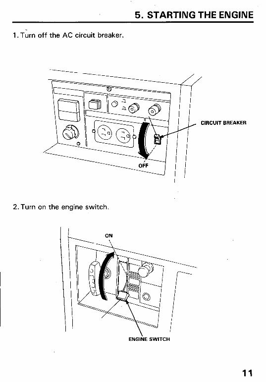
5. STARTING THE ENGINE
1. Turn off the AC circuit breaker.
, CIRCUIT
2.Turn on the engine switch.
BREAKER
ENGliE SWITCH
11

3. Pull the choke knob out to close.
I II CHO/KE KNOB
4. Pull the starter rope lightly until resistance is felt, then pull briskly.
CAUTION: l Do not allow the starter grip to snap back. Return it slowly by hand. l Do not let the starter rope rub against the generator body or the rope will
wear out prematurely.
NOTE: Make sure the pilot lamp comes on. If not, check the bulb filament.
STARTER GRIP
12

5. Push the choke knob in as the engine warms up.
CHOKE KNOB
Oil Alert System
Before the oil level in the crankcase can fall below a safe limit, the Oil Alert System will automatically shut off the engine. The Oil Alert Lamp will light when the recoil starter grip is pulled.
To restart, add enough recommended engine oil to bring the oil level to the upper level mark on the dipstick (See page 81, and restart the engine.
OIL ALERT LAMP
ENGINE SWITCH
NOTE: The engine switch will remain in the ON position if the engine is stopped by the Oil Alert System.
13

6. GENERATOR USE
l To prevent electrical shock from faulty appliances, the generator should be grounded. Connect a length of heavy wire between the ground ter- minal and an external ground source.
l Connections for standby power to a building’s electrical system must be made by a qualified electrician and must comply with all applicable laws and electrical codes. Improper connections can allow electrical current from the generator to backfeed into the utility lines. Such backfeed may electrocute utility company workers or others who contact the lines dur- ing a power outage, and when utility power is restored, the generator may explode, burn, or cause fires in the building’s electrical system.’
CAUTION l Limit operation requiring maximum power (2.2kVA) to 30 minutes.
For continuous operation,, do not exceed the rated power of 2.0 kVA. In either case, the total wattage of all appliances connected must be considered.
l Most appliance motors require more than their rated wattage for start- up-
l Do not exceed the current limit specified for any one receptacle.
14

AC applications
1. Start the engine and make sure the pilot lamp comes on. If not, check the filament.
2. Switch on the AC Circuit Breaker.
NOTE: Although voltage adjustment is usually not required, fine ad- justments may be made by turning the voltage adjustment knob. Use the generator at the specified voltage (12OV).
3. Plug in the appliance; always use three-pronged plugs.
CAUTION: Be sure that appliances do not exceed the generator’s rated load capacity for more than 30 minutes and that they never exceed the maximum load capacity. Substantial overloading will switch off the circuit breaker. Marginal overloading may not switch off the circuit breaker, but it will shorten the service life of the generator. Be sure that all appliances are in good working order before connecting them to the generator. If an appliance begins to operate abnormally, becomes sluggish, or stops suddenly, turn off the circuit breaker and the generator engine switch immediately. Then disconnect the appliance and examine it for signs of malfunction.
NOTE: If an overloaded circuit causes the AC circuit breaker to switch off, reduce the electrical load on the circuit and wait a few minutes before resetting the circuit breaker.
VOLT METER PILOT LAMP
VOLTAGE ADJUSTMENT KN
15

DC application ’
The DC terminals may be used for charging 12 volt automotive-type batteries only.
l The battery gives off explosive gases; keep sparks, flames and cigarettes away. Provide adequate ventilation when charging or using batteries in an enclosed space.
l The battery contains sulfuric acid (electrolyte). Contact with skin or eyes may cause severe burns. Wear protective clothing and a face shield. - If electrolyte gets on your skin, flush with water. -If electrolyte gets in your eyes, flush with water for at least 15
minutes and call a physician immediately. l Electrolyte is poisonous.
- If swallowed, drink large quantities of water or milk and follow with milk of magnesia or vegetable oil and call a physician.
l KEEP OUT OF REACH’OF CHILDREN. l To prevent the possibility of creating a spark near the battery, connect
charging cables first to the battery, then to the generator. Disconnect cables first at the generator.
l Before connecting charging cables to a battery that is installed in a vehi- cle, disconnect the vehicle’s grounded battery cable. Reconnect the vehicle’s grounded battery cable after the charging cables are removed. This procedure will prevent the possibility of a short circuit and sparks if you make accidental contact between a battery terminal and the vehi- cle’s frame or body.
CAUTION: l Do not attempt to start an automobile engine while the generator is still
connected to the battery. The generator may be damaged. l Connect the positive battery terminal to the positive generator terminal.
Do not reverse the charging cables or serious damage to the generator and/or battery may occur.
NOTE: DC CIRCUIT BREAKER NEGATIVE TERMINAL
l The DC terminals may be used while the AC power is in use.
l An overloaded DC circuit will trip the DC circuit protector (push but- ton comes out). If this happens, wait a few minutes before pushing in the circuit protector to resume operation.
16
POSITIVE TERMINAL (RED)
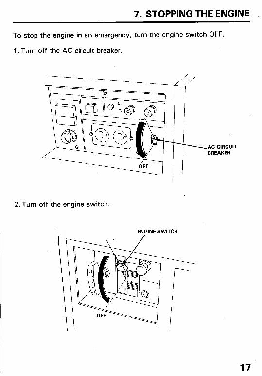
7. STOPPING THE ENGINE
To stop the engine in an emergency, turn the engine switch OFF.
1 .Turn off the AC circuit breaker.
I 2.Turn off the engine switch.
I I ENGINE SWITCH
.AC CIRCUIT BREAKER
17
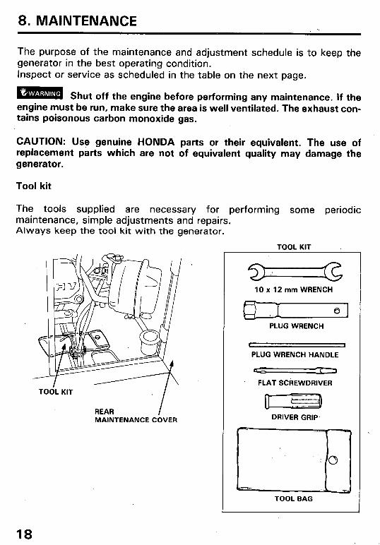
8. MAINTENANCE
The purpose of the maintenance and adjustment schedule is to keep the generator in the best operating condition. Inspect or service as scheduled in the table on the next page.
cmml Shut off the engine before performing any maintenance. If the engine must be run, make sure the area is well ventilated. The exhaust con- tains poisonous carbon monoxide gas.
CAUTION: Use genuine HONDA parts or their equivalent. The use of replacement parts which are not of equivalent quality may damage the generator.
Tool kit
The tools supplied are necessary for performing some periodic maintenance, simple adjustments and repairs. Always keep the tool kit with the generator.
TOOL KIT
f
TOOL KIT
REAR MAINTENANCE COVER
lOx12mmWRENCH
I 0 PLUG WRENCH
I 1
PLUG WRENCH HANDLE
IL- Cl
FLAT SCREWDRIVER
0 ( D DRIVER GRIP
TOOL BAG
18

Maintenance Schedule
REGULAR SERVICE PERIOD Performed
Engine oil Check level
Chance
Air cleaner
Spark arrester
Spark plug
Check
Clean
Clean
Clean-Readjust
Fuel sediment cup Clean
Valve clearance Check-Readjust
Fuel tank and strainer Clean
Fuel line Check (Replace if necessary)
EACH USE
0
0
FIRST MONTH
OR 20 HRS
0
0 0 =I=
EVERY YEAR
OR 300 HRS
O(2) O(2)
Every 3 Years (2)
NOTE: (1) Service more frequently when used in dusty areas. (2) These items should be serviced by an authorized Honda dealer, unless
the owner has the proper tools and is mechanically proficient. See the Honda Shop Manual.
19

Changing oil
Drain the oil while the engine is still warm to assure rapid and complete draining.
1. Open the front maintenance cover. 2. Remove the drain bolt and filler cap, and drain the oil. Retighten the bolt
securely. 3. Refill with the recommended oil (see page 8) and check the level. 4. Close and latch the front maintenance cover.
OIL CAPACITYi 0.6P (0.63 US qt)
OIL DRAIN BOLT
UPPER LEVEL 0.6P (0.63 US qt)
OIL FILLER CAP
CAUTION: Used motor oil may cause skin cancer if repeatedly left in con- tact with the skin for prolonged periods. Although this is unlikely unless you handle used oil on a daily basis, it is still advisable to thoroughly wash your hands with soap and water as soon as possible after handling used oil.
NOTE: Please dispose of used motor oil in a manner that is compatible with the environment. We suggest you take it in a sealed container to your local service station for reclamation. Do not throw it in the trash or pour it on the ground.
20

Air cleaner service
A dirty air cleaner will restrict air flow to the carburetor. To prevent car- buretor malfunction, service the air cleaner regularly (page 18). Service more frequently when operating the generator in extremely dusty areas.
m Never use gasoline or low flash point solvents for cleaning the air cleaner element. A fire or explosion could result.
CAUTION: Never run the generator without the air cleaner. Rapid engine wear will result.
1. Open the rear maintenance cover. 2. Unscrew the wing nut and then
remove the air cleaner cover and air cleaner element.
3. Wash the element in a nonflam- mable or high flash point solvent and dry it thoroughly.
4. Soak the element in clean engine oil and squeeze out the excess oil.
5. Reinstall the air cleaner element, the cover and the wing nut.
6. Close and latch the rear main- tenance cover.
AIR CLEANER COVER
WING NUT
AIR CLEANER ELEME
21

Spark plug service
Recommended spark plug: BPRGES (NGK)’ W20EPR-U (ND)
To ensure proper engine operation, the spark plug must be properly gapped and free of deposits.
1. Open the rear maintenance cover. 2. Remove the spark plug cap. 3. Clean any dirt from around the spark plug base. 4. Use the wrench,supplied in the tool kit to remove the spark plug.
5. Visually inspect the spark plug. Discard it if the insulator is cracked or chipped. Clean the spark plug with a wire brush if it is to be reused.
6. Measure the plug gap with a feeler gauge. The gap should be .0.7-0.8 mm (0.028-0.031 in). Correct as necessary by carefully bending the side electrode.
0.7-0.8 mm (0.028-0.031 in)
22

7. Inspect the plug washer and then thread the plug in by hand to prevent cross threading.
8. After a new spark plug has been seated by hand, it should be tightened l/2 turn with a wrench to compress its washer. If a used plug is being reinstalled, it should only require l/8 to l/4 turn after being seated.
CAUTION: l The spark plug must be securely tightened. An improperly tightened plug
can become very hot and could possibly damage the generator. l Never use a spark plug with an improper heat range.
9. Close and latch the rear maintenance cover.
23

Fuel sediment cup service ,
The filter prevents dirt or water which may be in the fuel tank from entering the carburetor. If the engine has not been run for a long time, the filter should be cleaned.
1. Open the front maintenance cover. 2. Turn the engine switch to STOP. Remove the sediment cup by turning it
counterclockwise. 3. Clean the cup and rubber gasket in solvent thoroughly. 4. Reassemble the rubber gasket and sediment cup. Tighten securely. 5. Close and latch the front maintenance cover.
Emm After installing the sediment cup, check for fliel leaks and make sure the area is dry before starting the engine.
SEDIMENT CUP
24.

Spark arrester maintenance
w If the generator has been running, .the muffler will be very hot. Allow it to cool before proceeding.
CAUTION: The spark arrester must be serviced every 100 hours to main- tain its efficiency.
1. Remove the nine 6 mm bolts, the handle and right side cover.
RIGHT SIDE COVER
HANDLE
6 mm BOLTS
2. Remove the two 5 mm pan screws, and the spark arrester.
SPARK ARRESTER
5 mm PAN SCREW
25
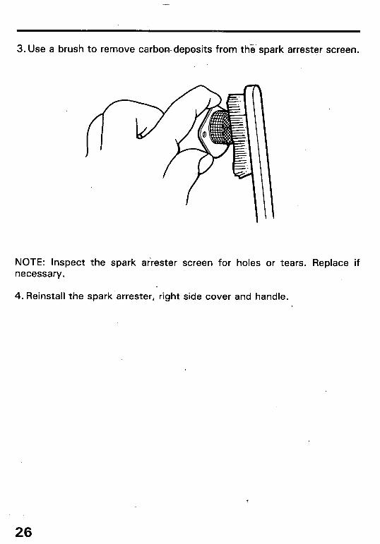
3. Use a brush to remove carbon-deposits from the spark arrester screen.
NOTE: Inspect the spark airester screen for holes or tears. Replace if necessary.
4. Reinstall the spark arrester, right side cover and handle.
26

9. TRANSPORTING/STORAGE
m When transporting the generator, turn the engine switch OFF and keep the generator level to prevent fuel spillage. Fuel vapor or spilled fuel may ignite.
Before storing the unit for an extended period: 1. Be-sure the storage area is free of excessive .humidity.and dust. 2. Drain the fuel-
a. Open the rear maintenance cover. b. Turn the engine switch to ON and
then loosen the carburetor drain screw. Drain the gasoline from the carburetor and fuel tank into a suitable container.
m Gasoline is extremely flammable and is explosive under certain conditions. Perform this task in a well ventilated area with the engine stopped. Do not smoke or allow flames or sparks in the area during this procedure.
c. Tighten the carburetor drain screw, turn the engine switch to OFF and close the rear mainte- nance cover.
3. Slowly pull the starter grip until resistance is felt. At this point, the piston is coming up on its compression stroke and both the intake and exhaust valves are closed. Storing the engine in this position will help to protect it from internal corrosion.
STARTER GRIP
27
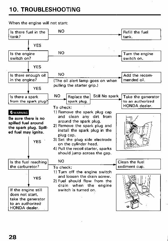
10. TROUBLESHOBTBNG
When the engine will not start:
Is there fuel in the tank?
NO Refill the fuel tank.
Is the engine switch on?
NO Turn the engine switch on. I
Is there enough oil NO Add the recom- in the engine? ‘(The oil alert lamp goes on when mended oil.
I YES pulling the starter grip.)
9 Is the1 re a spark NO Replace the Still No spar Take the generator
1 from the spark plug? spark plug. to an authorized
Be sure there is no spilled fuel around the spark plug. Spill- ed fuel may ignite.
YES
.- To check: I) Remove the spark plug cap
and clean any dirt from around the spark plug.
2) Remove the spark plug and install the spark plug in the plug cap.
3) Set the plug side electrode on the cylinder head.
4) Pull the recoil starter, sparks should jump across the gap.
and loosen the drain screw. 2) Fuel should flow from the
drain when the engine switch is turned on.
does not start, take the generator to an authorized
HONDA dealer.
Is the fuel reaching NO Clean the fuel the carburetor? To check: sediment cup.
I) Turn off the engine switch
28
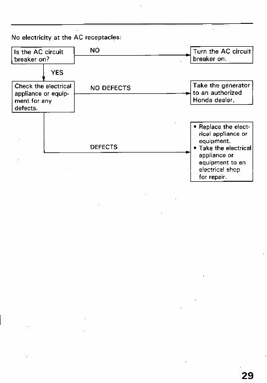
No electricity at the AC receptacles:
Is the AC circuit breaker on?
YES
NO Turn the AC, circuit breaker on.
Check the electrical appliance or equip- r ment for any defects.
NO DEFECTS Take the generator b to an authorized
Honda dealer.
DEFECTS
l Replace the elect rical appliance or equipment.
l Take the electrici appliance or equipment to an electrical shop for repair.
29

11. WIRING DIAGRAM
I
1 BI 1 BLACK I
30

.I 2. SPECIFICATIONS
Dimensions
Length x Width x Height
Dry Weight
755 x ‘480 x 590 mm (29.7 x 18.9 x 23.2 in)
69 kg (152.1 lb)
Engine
Model Engine Type
Displacement [Bore x Stroke1 Compression Ratio Engine Speed Cooling System Ignition System Oil Capacity Fuel Tank Capacity Spark Plug
HONDA GX140 4-Stroke, O.H.V. 1 cylinder (25 O tilted) 144 cm3 (8.8 cu in) 64 x 45 mm (2.5 x 1.8 in) 8.75 : 1 3600 rpm Forced air cooled Transistorized magneto 0.6 l (0.63 US qt) 8.3 l (2.19 US gal) . BPRGES (NGK) W20EPR-U (ND)
Generator
Rated voltage 12ov Rated frequency 60Hz
AC output Rated ampere 16.7 (A)
Rated output 2.0 kVA (2OOOW)
Maximum output 2.2 kVA (22OOW)
31
High altitude operation
At high altitude, the standard carburetor air-fuel mixture will be excessively rich. Performance will decrease, and fuel consumption will increase.
High altitude performance can be improved by installing a smaller diameter main fuel jet in the carburetor and readjusting the pilot screw. If you always operate the generator at altitudes higher than 6,000 feet above sea level, have your authorized Honda Generator dealer perform these carburetor modifications.
Even with suitable carburetor jetting, engine horsepower will decrease ap- proximately 3.5% for each 1,000 foot increase in altitude. The affect of altitude on horsepower will be greater than this if no carburetor modifica- tion is made.
CAUTION: Operation of the generator at an altitude lower than the car- buretor is jetted for may result in reduced performance, overheating, and serious engine damage caused by an excessively lean air/fuel mixture.
32

13. WARRANTY SERVICE
Owner Satisfaction
Your satisfaction and goodwill are important to your dealer and to us. All Honda warranty details are explained in the Distributor’s Limited Warran- ty. Normally, any problems concerning the product will be handled by your dealer’s service department. If you have a warranty problem that has not been handled to your satisfaction, we suggest you take the following action:
l Discuss your problem with a member of dealership management. Often complaints can be quickly resolved at that level. If the problem has already been reviewed with the Service Manager, contact the owner of the dealership or the General Manager.
l If your problem still has not been resolved to your satisfaction, contact:
American Honda Motor Co., Inc. P.O. Box 50 Gardena, California 90247-0805 Telephone: (213) 604-2400
We will need the following information in order to assist you:
- Your name, address, and telephone number - Product model and serial number - Date of purchase - Dealer name and address - Nature of the problem
After reviewing all the facts involved, you will be advised of what action can be taken. Please bear in mind that your problem will likely be resolved at the dealership, using the dealer’s facilities, equipment, and personnel, so it is very important that your initial contact be with the dealer.
Your purchase of a Honda product is greatly appreciated by both your dealer and American Honda Motor Co., Inc. We want to assist you in every way possible to assure your complete satisfaction with your purchase.
33

Current customer service contact information: United States, Puerto Rico, and U.S. Virgin Islands: Honda Power Equipment dealership personnel are trained professionals. They should be able to answer any question you may have. If you encounter a problem that your dealer does not solve to your satisfaction, please discuss it with the dealership's management. The Service Manager or General Manager can help. Almost all problems are solved in this way.
If you are dissatisfied with the decision made by the dealership's management, contact the Honda Power Equipment Customer Relations Office. You can write:
American Honda Motor Co., Inc. Power Equipment Division Customer Relations Office 4900 Marconi Drive Alpharetta, GA 30005-8847
Or telephone: (770) 497-6400 M-F, 8:30 am - 7:00 pm EST
When you write or call, please provide the following information:
• Model and serial numbers
• Name of the dealer who sold the Honda power equipment to you
• Name and address of the dealer who services your equipment
• Date of purchase
• Your name, address, and telephone number
• A detailed description of the problem

MEMO
34

MEMO
35

MEMO
36

