m-pact new - publication library | ge industrial...
TRANSCRIPT

GE Industrial Solutions
M-PACTAir Circuit Breaker 400-4000A
New

GE
Industrial Solutions
2010 World's Most Innovative Companies
2008 World’s Most Respected Companies 2007 World’s Best R&D Companies
2011 World’s Most Admired Companies
2011 Best Global Brand
2009 World’s Most Respected Companies
GE is a diversified organization covering a myriad of market segments, including infrastructure, finance and media.
From energy, water, transportation and health to access to money and information, GE serves customers in more than
100 countries and employs more than 300,000 people worldwide.
The company traces its beginnings from Thomas A. Edison, who established the Edison Electric Light Company in 1878.
In 1892, a merger of Edison General Electric Company and Thomson-Houston Electric Company created the General
Electric Company. GE is the only company listed in the Dow Jones Industrial Index today that was also included in the
original index in 1896.
GE Industrial Solutions, a division of GE Energy Management, is a global leading provider in power distribution, offering a
wide range of products which include medium and low voltage power distribution equipment and components, and
motor & control systems that are safe, reliable and offer high performance. Its innovative solutions can improve energy
efficiency and environmental impact in power plants, power grids, oil & gas, mining, data center, overseas EPC,
industrial manufacturing, rail transportation, commercial buildings, residential houses, renewable energy and many
other industries.
GE is one of the worldwide partners of the Olympic Games. In 2008, GE assisted Beijing with this tremendous event, which was unprecedented in scale and first-class in its use of science and technology, offering a series of innovative solutions and products for around 400 Olympic infrastructure projects, covering fields in electricity distribution, lighting, security, water processing, benefiting some 37 Olympic venues and 168 commercial buildings. GE also brought its experiences to the 2010 Expo in Shanghai, Asia Games in Guangzhou, Vancouver Olympic Games and continued through to the London 2012 Olympic Games.

M-PACTAir Circuit Breaker 400-4000A

A
B
C
A.2
Air circuit breakers 400A-4000A
Technical overview
Order codes
Wiring diagramsDimensional drawings
A.4 Fixed Circuit BreakerA.6 Withdrawable Circuit BreakerA.7 CharacteristicsA.9 State of the Art Electronic Trip UnitsA.11 Time Current CurvesA.19 M-PACT Accessories
Technical overview
M-PACT
A
B
C
Tech
nica
l ove
rvie
w
A.3
Notes
A
B
C
A.4
Specification
Approvals
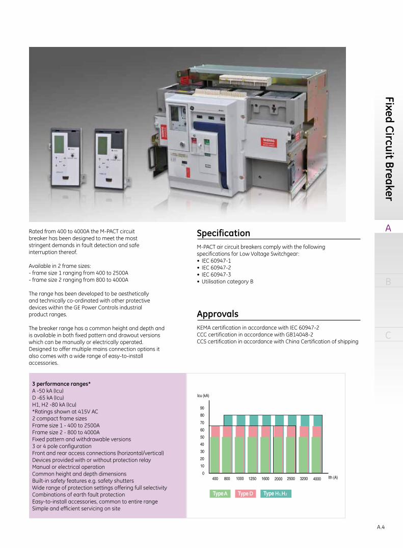
Rated from 400 to 4000A the M-PACT circuitbreaker has been designed to meet the moststringent demands in fault detection and safeinterruption thereof.
Available in 2 frame sizes:- frame size 1 ranging from 400 to 2500A- frame size 2 ranging from 800 to 4000A
The range has been developed to be aestheticallyand technically co-ordinated with other protectivedevices within the GE Power Controls industrialproduct ranges.
The breaker range has a common height and depth andis available in both fixed pattern and drawout versionswhich can be manually or electrically operated.Designed to offer multiple mains connection options italso comes with a wide range of easy-to-installaccessories.
M-PACT air circuit breakers comply with the followingspecifications for Low Voltage Switchgear:• IEC 60947-1• IEC 60947-2• IEC 60947-3• Utilisation category B
KEMA certification in accordance with IEC 60947-2CCC certification in accordance with GB14048-2CCS certification in accordance with China Certification of shipping
3 performance ranges*A -50 kA (Icu)D -65 kA (Icu)H1, H2 -80 kA (Icu)*Ratings shown at 415V AC2 compact frame sizesFrame size 1 - 400 to 2500AFrame size 2 - 800 to 4000AFixed pattern and withdrawable versions3 or 4 pole configurationFront and rear access connections (horizontal/vertical)Devices provided with or without protection relayManual or electrical operationCommon height and depth dimensionsBuilt-in safety features e.g. safety shuttersWide range of protection settings offering full selectivityCombinations of earth fault protectionEasy-to-install accessories, common to entire rangeSimple and efficient servicing on site
A D H1,H2
Fixed Circuit Breaker

M-PACT
A
B
C
Tech
nica
l ove
rvie
w
A.5
Fixed circuit breakerAll M-PACT fixed pattern air circuit breakers incorporate a stored energy mechanism. The spring can be charged either manually or electrically via a motor operator that is automatically activated after the closing operation.IP43 front panel and door escutcheon seals are standard features with IP20 protected secondary isolating contacts. For enhanced protection, an optionalIP54 door panel is also available.
• Trip-free operating mechanism• Positive 'ON/OFF' contact indication• Mechanical/electrical anti-pumping device• Charging spring status indication (optional)• Ergonomic manual spring charging handle• Field-mountable range of accessories• Auxiliary switches 5 NO and 3 NC, 10A 250V (standard)• Mechanical Trip Alarm switch (1NO) (optional)• Padlockable push-button cover• Mechanical cable interlocking (optional)• Termination: rear, horizontal or front access (optional)• Electrical clearances according to IEC60947-2• Front access of secondary terminals for simple connection
8
9
InstallationFixed pattern M-PACT can be fastened into any suitable switchboard or cubicle arrangement using four M8 bolts.Clearance is only required above the unit for the removal and inspection of the arc chutes (see dimensional drawings for mounting details and recommended clearance distances).An earthing point is provided on either side of the circuit breaker.
Power Supply
1. Motorised spring charging unit (optional)2. M-PRO Protection Relay (optional)3. Secondary contacts4. Shunt trip (optional)5. Closing coil (optional)6. Undervoltage release (optional)7. Manual charging handle8. ON/OFF push-buttons9. Push-button padlockable covers10. Positive contact indication11. Charging spring status indication12. Mounting plate
All stated short circuit ratings are certified with incoming supply connection made to either upper or lower terminals.
12
3
2
7
10
11
4 5
1
6

A
B
C
A.6
8 6
Withdrawable circuit breakerPre-mounted into a self-contained 'cassette', this versatile circuit breaker can be inserted or withdrawn via sliding rails using a racking drive mechanism controlled by a racking handle.It provides three set positions:Disconnected / Test / Connected.Any attempt to withdraw the unit whilst in service will automatically trip the breaker, either by the racking position safety mechanism or by the insertion of the racking handle. It can be racked to the dis-connected position with the cubicle door closed or open.
• Insulated, earthed steel shutters to isolate the main contact zone• Front access padlocking for safety shutters• Secure padlocking in the "Disconnect" position• Clearly visible operational position indication• Carriage position switch (optional)• Termination: Flat copper palms (standard) with captive M10 fixing nuts• 'T' terminal adaptors for horizontal/vertical connection (optional)• Front access connections (optional)• Automatic disconnect of secondary circuits• Lifting lugs for ease of removing the circuit breaker from the cassette• Front access of secondary terminals for simple connection• Cassette side mounting fixing parts (optional)
Installation
Power Supply
Circuit breakers are delivered pre-mounted in thecassette (standard)Versatile fixing arrangements allow mounting onto any switchboard or cubicle using four M8 bolts (see dimensional drawings for mounting details and recommended clearance distances)Earthing point situated on the right hand side of cassette (front view)
1. Carriage position switch (optional)2. Extension rail3. Earthed steel safety shutter4. Secondary terminals5. 2 way cable interlock mechanism (optional)6. Racking handle (storage)7. Padlocking for safety shutters8. Insertion hole for racking handle9. Padlocking in the DISCONNECTED position10. Operational position indication11. Key interlock (optional)
All stated short circuit ratings are certified with incoming supply connection made to either upper or lower terminals.
Withdraw
able circuit breaker
5
4
11
7
10
9
2
1
3
4

M-PACT
A
B
C
Tech
nica
l ove
rvie
w
A.7
Characteristics
Design and specifications are subject to changes without notice.
Selectivity Temperature Deratings
The following table shows the conditions to satisfy full selectivity between UP-STREAM and DOWN-STREAM devices. Up-stream: M-PACTDown-stream: M-PACTST delay 50 ms minimum between up-stream and downstream ACB Multiplication coefficient between LT-ratings≥1,56
Free Air(1)
The M-PACT ACBs may operate at higher ambient temperatures than 40oC in certain installation conditions. In this case the current rating in Amperes should be reduced as indicated below.
The figures specified apply to withdrawable ACB's with flat face vertical copper connections(1) Protection degree IP00.For use in enclosures with interior temperatures of 40℃ to 70℃ the relevant IP values can be applied.
Down-stream
- 400 800 1000 1250 1600 2000 2500 3200 4000400 - - - - - - - - -800 Full - - - - - - - -
1000 Full - - - - - - - -1250 Full Full - - - - - - -1600 Full Full Full - - - - - -2000 Full Full Full Full - - - - -2500 Full Full Full Full Full Full - - -3200 Full Full Full Full Full Full - - -4000 Full Full Full Full Full 2000 Full - -
Up-
stre
am
AmblentTemperature
Current Rating (A)800 1000 1250 1600 2000 2500 3200 4000
50℃ 800 1000 1250 1600 2000 2450 3200 372760℃ 800 1000 1250 1445 2000 2232 3200 336765℃ 800 1000 1250 1364 2000 2092 3019 317570℃ 800 1000 1250 1280 1970 1970 2831 2978
Performance DataCharacteristic Symbol UnitsRated current (40℃) 400 800 1000 1250 1600 2000 2500 3200 4000
Endurance (number of operating cycles)Mechanical (with maintenance) 20000 20000 20000 20000 20000 20000 20000 20000 20000
Mechanical (without maintenance) 10000 10000 10000 10000 10000 10000 10000 10000 10000Electrical (at rated current) 5000 5000 5000 5000 5000 5000 5000 5000 5000
Rated service voltage (50/60 Hz) Ue V 690 690 690 690 690 690 690 690 690Rated insulation voltage (50/60 Hz) Ui V 1000 1000 1000 1000 1000 1000 1000 1000 1000Rated impulse withstand voltage Uimp V 8000 8000 8000 8000 8000 8000 8000 8000 8000
Number of poles 3 & 4 3 & 4 3 & 4 3 & 4 3 & 4 3 & 4 3 & 4 3 & 4 3 & 4Rating of 4th pole 100% 100% 100% 100% 100% 100% 100% 100% 100%
ACB type A D A D H1 H2 A D H1 H2 A D H1 H2 A D H1 H2 A D H1 H2 A D H1 H2 A D H1 H2 A D H1 H2Frame size 1 1 1 1 2 2 1 1 2 2 1 1 2 2 1 1 2 2 1 1 2 2 1 1 2 2 2 2 2 2 2 2 2 2
Rated ultimate short-circuit Icu kA (rms) 220V 50 65 50 65 80 80 50 65 80 80 50 65 80 80 50 65 80 80 50 65 80 80 50 65 80 80 50 65 80 80 50 65 80 80breaking capacity 415V 50 65 50 65 80 80 50 65 80 80 50 65 80 80 50 65 80 80 50 65 80 80 50 65 80 80 50 65 80 80 50 65 80 80
500V 50 65 50 65 65 80 50 65 65 80 50 65 65 80 50 65 65 80 50 65 65 80 50 65 65 80 50 65 65 80 50 65 65 80600V 50 50 50 50 50 65 50 50 50 65 50 50 50 65 50 50 50 65 50 50 50 65 50 50 50 65 50 50 50 65 50 50 50 65690V 40 40 40 40 40 60 40 40 40 60 40 40 40 60 40 40 40 60 40 40 40 60 40 40 40 60 40 40 40 60 40 40 40 60
Rated service short-circuit Ics kA (rms) 220V 50 65 50 65 80 80 50 65 80 80 50 65 80 80 50 65 80 80 50 65 80 80 50 65 80 80 50 65 80 80 50 65 80 80breaking capacity 415V 50 65 50 65 80 80 50 65 80 80 50 65 80 80 50 65 80 80 50 65 80 80 50 65 80 80 50 65 80 80 50 65 80 80
500V 50 65 50 65 65 80 50 65 65 80 50 65 65 80 50 65 65 80 50 65 65 80 50 65 65 80 50 65 65 80 50 65 65 80600V 50 50 50 50 50 65 50 50 50 65 50 50 50 65 50 50 50 50 50 50 50 65 50 50 50 65 50 50 50 65 50 50 50 65690V 40 40 40 40 40 60 40 40 40 60 40 40 40 60 40 40 40 60 40 40 40 60 40 40 40 60 40 40 40 60 40 40 40 60
Rated short time withstand current1 second Icw 415/690VAc kA (rms) 50 65/50 50 65/50 65 80 50 65/50 65 80 50 65/50 65 80 50 65 65 80 50 65 65 80 50 65 65 80 50 65 65 80 50 65 65 803 seconds Icw kA (rms) 40 50 40 50 50 50 40 50 50 50 40 50 50 50 40 50 50 50 40 50 50 50 40 50 50 50 40 50 50 50 40 50 50 50Rated short-circuit making capacity Icm kA (peak) 415V 105 143 105 143 176 176 105 143 176 176 105 143 176 176 105 143 176 176 105 143 176 176 105 143 176 176 105 143 176 176 105 143 176 176
500V 105 143 105 143 143 176 105 143 143 176 105 143 143 176 105 143 143 176 105 143 143 176 105 143 143 176 105 143 143 176 105 143 143 176600V 105 105 105 105 105 143 105 105 105 143 105 105 105 143 105 105 105 143 105 105 105 143 105 105 105 143 105 105 105 143 105 105 105 143690V 84 84 84 84 84 105 84 84 84 105 84 84 84 105 84 84 84 105 84 84 84 105 84 84 84 105 84 84 84 105 84 84 84 105
Power dissipation at In (Fixed breaker) Watts 15 10 63 43 23 20 106 68 36 32 175 105 60 53 284 196 98 86 224 224 163 143 351 351 255 223 418 418 418 366 571 571 571 571Power dissipation at In (Withdrawable) Watts 30 21 127 86 49 43 211 135 77 68 351 211 128 113 574 392 209 184 490 490 347 306 765 765 542 478 888 888 888 783 1224 1224 1224 1224

A
B
C
A.8
Dimensions in mmFrame
SizeRating
(A) Poles Type Height(1) Width Depth(2)
1 400 to 2500 3 Withdrawable 440 329 422Fixed 430 342 352
4 Withdrawable 440 429 422Fixed 430 442 352
2 800 to 4000 3 Withdrawable 440 419 424Fixed 430 432 352
4 Withdrawable 440 549 424Fixed 430 562 352
Weights (kg)A range D range H range
Fixed pattern ACB Frame 3 Pole 4 Pole 3 Pole 4 Pole 3 Pole 4 Pole400 to 1600A 1 39 49 39 49 / /
2000 to 2500A 1 43 54 43 54 / /800 to 3200A 2 53 68 53 68 53 68
4000A 2 53 68 53 68 53 68
Withdrawable ACB Frame 3 Pole 4 Pole 3 Pole 4 Pole 3 Pole 4 Pole400 to 1600A 1 68 79 68 79 / /
2000 to 2500A 1 74 85 74 85 / /800 to 3200A 2 90 109 90 109 90 109
4000A 2 113 128 113 128 113 128
Catalog NO.ConfigurationMP A 3 1 F 16
Ratings:
04-400A, 08-800A10-1000A, 12-1250A16-1600A, 20-2000A25-2500A, 32-3200A40-4000A
Installation: F-fixed W-withdrawable
Type: 1-Frame1 2-Frame2
Breaking Capacity: A, D, H1, H2
M-PACT
Pole: 3-3P 4-4P*
Recommended Minimum Copper SizeIn accordance with IEC 60947-2
Rating (A) Copper / phase400 2 x 50 x 5800 2 x 50 x 5
1000 2 x 60 x 51250 2 x 100 x 51600 2 x 100 x 52000 3 x 100 x 52500 4 x 100 x 53200 4 x 100 x 104000 4 x 100 x 10 + 1 x 100 x 5
(1) Height is from mounting surface to highest part of the ACB.(2) Depth is from the cubicle door to the back of terminals.* For a 4P unit with a neutral, please specify on the selection form if it is required on the LHS or RHS (viewed from the front), the default value is netural on the right. * Letter 'L' & 'R' only for type selection, not shown on nameplate.
Characteristics
Performance DataCharacteristic Symbol UnitsRated current (40℃) 400 800 1000 1250 1600 2000 2500 3200 4000
Endurance (number of operating cycles)Mechanical (with maintenance) 20000 20000 20000 20000 20000 20000 20000 20000 20000
Mechanical (without maintenance) 10000 10000 10000 10000 10000 10000 10000 10000 10000Electrical (at rated current) 5000 5000 5000 5000 5000 5000 5000 5000 5000
Rated service voltage (50/60 Hz) Ue V 690 690 690 690 690 690 690 690 690Rated insulation voltage (50/60 Hz) Ui V 1000 1000 1000 1000 1000 1000 1000 1000 1000Rated impulse withstand voltage Uimp V 8000 8000 8000 8000 8000 8000 8000 8000 8000
Number of poles 3 & 4 3 & 4 3 & 4 3 & 4 3 & 4 3 & 4 3 & 4 3 & 4 3 & 4Rating of 4th pole 100% 100% 100% 100% 100% 100% 100% 100% 100%
ACB type A D A D H1 H2 A D H1 H2 A D H1 H2 A D H1 H2 A D H1 H2 A D H1 H2 A D H1 H2 A D H1 H2Frame size 1 1 1 1 2 2 1 1 2 2 1 1 2 2 1 1 2 2 1 1 2 2 1 1 2 2 2 2 2 2 2 2 2 2
Rated ultimate short-circuit Icu kA (rms) 220V 50 65 50 65 80 80 50 65 80 80 50 65 80 80 50 65 80 80 50 65 80 80 50 65 80 80 50 65 80 80 50 65 80 80breaking capacity 415V 50 65 50 65 80 80 50 65 80 80 50 65 80 80 50 65 80 80 50 65 80 80 50 65 80 80 50 65 80 80 50 65 80 80
500V 50 65 50 65 65 80 50 65 65 80 50 65 65 80 50 65 65 80 50 65 65 80 50 65 65 80 50 65 65 80 50 65 65 80600V 50 50 50 50 50 65 50 50 50 65 50 50 50 65 50 50 50 65 50 50 50 65 50 50 50 65 50 50 50 65 50 50 50 65690V 40 40 40 40 40 60 40 40 40 60 40 40 40 60 40 40 40 60 40 40 40 60 40 40 40 60 40 40 40 60 40 40 40 60
Rated service short-circuit Ics kA (rms) 220V 50 65 50 65 80 80 50 65 80 80 50 65 80 80 50 65 80 80 50 65 80 80 50 65 80 80 50 65 80 80 50 65 80 80breaking capacity 415V 50 65 50 65 80 80 50 65 80 80 50 65 80 80 50 65 80 80 50 65 80 80 50 65 80 80 50 65 80 80 50 65 80 80
500V 50 65 50 65 65 80 50 65 65 80 50 65 65 80 50 65 65 80 50 65 65 80 50 65 65 80 50 65 65 80 50 65 65 80600V 50 50 50 50 50 65 50 50 50 65 50 50 50 65 50 50 50 50 50 50 50 65 50 50 50 65 50 50 50 65 50 50 50 65690V 40 40 40 40 40 60 40 40 40 60 40 40 40 60 40 40 40 60 40 40 40 60 40 40 40 60 40 40 40 60 40 40 40 60
Rated short time withstand current1 second Icw 415/690VAc kA (rms) 50 65/50 50 65/50 65 80 50 65/50 65 80 50 65/50 65 80 50 65 65 80 50 65 65 80 50 65 65 80 50 65 65 80 50 65 65 803 seconds Icw kA (rms) 40 50 40 50 50 50 40 50 50 50 40 50 50 50 40 50 50 50 40 50 50 50 40 50 50 50 40 50 50 50 40 50 50 50Rated short-circuit making capacity Icm kA (peak) 415V 105 143 105 143 176 176 105 143 176 176 105 143 176 176 105 143 176 176 105 143 176 176 105 143 176 176 105 143 176 176 105 143 176 176
500V 105 143 105 143 143 176 105 143 143 176 105 143 143 176 105 143 143 176 105 143 143 176 105 143 143 176 105 143 143 176 105 143 143 176600V 105 105 105 105 105 143 105 105 105 143 105 105 105 143 105 105 105 143 105 105 105 143 105 105 105 143 105 105 105 143 105 105 105 143690V 84 84 84 84 84 105 84 84 84 105 84 84 84 105 84 84 84 105 84 84 84 105 84 84 84 105 84 84 84 105 84 84 84 105
Power dissipation at In (Fixed breaker) Watts 15 10 63 43 23 20 106 68 36 32 175 105 60 53 284 196 98 86 224 224 163 143 351 351 255 223 418 418 418 366 571 571 571 571Power dissipation at In (Withdrawable) Watts 30 21 127 86 49 43 211 135 77 68 351 211 128 113 574 392 209 184 490 490 347 306 765 765 542 478 888 888 888 783 1224 1224 1224 1224

M-PACT
A
B
C
Tech
nica
l ove
rvie
w
A.9
State of the Art Electronic Trip Units
Plug'n Play MPRO-27 & MPRO-50
Main Adjustment Options
• A line offering a new range of electronic trip units designed to extend and/or upgrade the functionality offered by the existing M-PACT Plus air circuit breaker.
• Two types are available. The simple and effective MPRO-27 and the MPRO-50 offering extended functionality .
• Each has a LCD screen with ammeter and a menu driven setting interface, allowing a simple and accurate setting of all parameters.
• This global line of electronic trip units uses the most recent technology to offer each user an unique combination of selectivity speed and functionality.
Electronic trip units are normally supplied factory fitted. However spares are available that can be simply plugged into breakers installed in the field.
Each trip unit then needs to be adjusted to the required settings. If the installation is not powered up the installed battery pack or the seperately available test kit with Power Pack can be used as alternate power source.
The basic MPRO-27 type has been designed to replace the existing MPRO-17 and MPRO-18 plus units offering an extended functionality and a standard ammeter.
The MPRO-50 type replaces the existing MPRO-30 and MPRO-40 designscovering an extended functionality with protection devices as fuse links,overload protection and reduced instantaneous (RELT). Each MPRO-50 comes with a simple to connect 4 wire modbus communciation option.
• LT-LTD protection
• ST-STD protection
• I-protection
• Other protection features
Each device has an overload setting range of 0.4 to 1 times In and offer a choice of 22 time bands designed for use with circuit breakers.A second set of 22 time bands shaped to match the time current curves of fuses is available on the MPRO-50 type.
A timed delayed short circuit protection are installed with a current setting of 2 to 12 times the set LT current value. The short circuit protection time can be set, at one of 17 bands ranging from 90 milliseconds to 1 second. Optionaly this device can be set to one of three I2t curves.
A switchable and selective instantaneous protection with a setting range of 2 to 15 times the breaker rating that is programmed to wait one half cycle until the downstream device has reacted.
A host of other protection devices are available including: Ground Fault sum and Ground Fault source return (allowing UEF, SEF & REF) and a reduced instantaneous device. The reduced instanataneous device allows the user to conditionally programme the breaker to trip faster and at lower short circuit settings than it would on the standard instantaneuos device.This RELT device allows the user to reduce the short circuit current level and its time span, thus reducing the amount of electrical energy in the direct vicinity of the breaker.

A
B
C
A.10
Trip Unit MPRO-27 MPRO-50Setting InterfaceLCD screen allowing access to 4 distinct menu's X XTouch pad adjustments X XMultilingual X XAdjustable manual or automatic RESET option X XLong Time or Overload Current Protection13 current settings Ir 1, 0.95, 0.9. 0,85, 0.8, 0.75, 0.7, 0.65, 0.6, 0.55, 0.5, 0.45 & 0.4 x breaker rating In X X22 thermal protection (C type) time bands available ranging from class 0.5 to 40 (bands at 7.2 x Ir) X X22 I2t protection (F type {fuse} ) time bands available - XNeutral protection 0-50%-63%-100% X XPossibility to switch OFF - XCooling function and thermal memory X X
Short Time Short-Circuit Current Protection
Setting range from 1.5 to 12 x Ir (LT setting) X XSteps of 0.5 (a total of 22 settings) X XPossibility to switch OFF - X17 time delay settings (STDB) ranging from 30 to 940 milliseconds delay setting result ina 90 to 1000 milliseconds
X X
Clearance times to IEC 40979-1 and IEC 603643 I2t Protection time bands availableInstantaneous Short-Circuit Current• StandardIi setting range from 2 to 15 x breaker rating In X XSteps of 0.5 (a total of 28 settings) X XPossibility to switch OFF X XSelective execution X XFixed instantaneous or HSIOC protection X X• ReducedIi setting range from 1.5 to 15 x Ie (primary setting) - XSteps of 0.5 (a total of 29 settings) - XPossibility to switch OFF - XRemote and local ON and OFF with position indication signal - XGround or Earth Fault ProtectionSetting range from 0.1 to 1 x In (breaker rating) (1) •(1) •(1)
Steps of 0.01 (a total of 92 settings) • •Possibility to switch OFF • •14 time delay settings (GFDB) ranging from 50 to 840 milliseconds delay setting resulting in a 110 to 900 milliseconds
• •
Clearance times to IEC 40979-1 and IEC 60364 • •3 I2t protection time bands available • •1 I4t protection time bands available • •Residual principle (UEF application possible) • •Source ground return principle - •UEF, REF and SEF applications possible - •Combinations of UEF, REF and SEF applications possible - •Other FunctionsCurrent measurement (L1, L2, L3, N) X XTrip target (trip reason indication) X XTrip info (magnitude / phase) X XTrip counter X XEvent logger (trip events) X XGeneral inputs (4 availble) - XGeneral relay outputs (4 available) - XRelay based on current level (load shedding) - XGood & bad health indicator - XWatchdog - XCommunication 2 way - XModbus - X24V DC auxiliary power supply X XTest kit with power support function • •
(1) A 24V auxiliary power supply is required.KeyX = Present• = Optional- = Not possible
State of the Art Electronic Trip Units

M-PACT
A
B
C
Tech
nica
l ove
rvie
w
A.11
Time Current CurvesExample of Full Time Current CurveTime Current Curve
The MPRO Electronic trip unit has many sophisticated setting features and an extremely broad setting range. On request we can provide complete Time Current Curves covering all installed protection devices.
The curves can be produced for any current setting within the range of the installed protection devices, for one or for a combination of two breakers.Please contact your local GE Sales Office for more information.
MPRO Electr onic Trip Unit
0,001
0,01
0,1
1
10
100
1000
10000
000001000010001
x Current in Amps (Strom in Ampere)
Trip
ping
Tim
e in
Sec
onds
(s)
Time Current CurveBreaker In= 2500A----------------------------------LT - Protection deviceSet at Ie= 2400AIr at 0,9 =2160ABand C-10
ST - Protection deviceSet at 6x Ir of 2160AIst=12960ABand STDB 10
I - Protection deviceSet at 12 x Ie of 2400AIi = 28800A
GF - Protection deviceSet at 0,6 x Ie of 2500A(Ig = 1500A)Band GFDB 6I²t ON & OFF
2h
7,2 x
Green & Light Blue Line = Full Clearing timeRed Line & Dark Blue Line = Non Tripping time
LT Band
ST Band
I I Band
HSIOC Band
GF Band
A
B
C
A.12
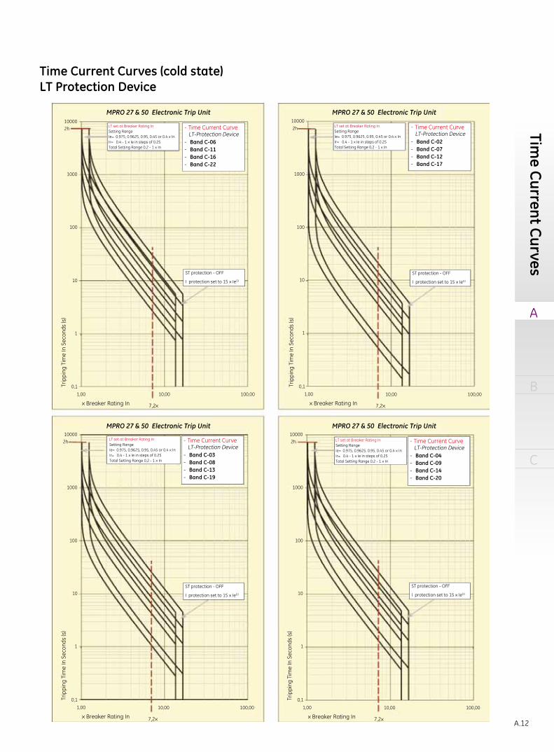
Time Current Curves (cold state)LT Protection Device
MPRO 27 & 50 Electronic Trip Unit MPRO 27 & 50 Electronic Trip Unit
MPRO 27 & 50 Electronic Trip Unit MPRO 27 & 50 Electronic Trip Unit
ST protection - OFF
I protection set to 15 x Ie(1)
ST protection - OFF
I protection set to 15 x Ie(1)
ST protection - OFF
I protection set to 15 x Ie(1)
ST protection - OFF
I protection set to 15 x Ie(1)
LT set at Breaker Rating InSetting RangeIe= 0.975, 0.9625, 0.95, 0.45 or 0.4 x InIr= 0.4 - 1 x Ie in steps of 0.25Total Setting Range 0,2 - 1 x In
LT set at Breaker Rating InSetting RangeIe= 0.975, 0.9625, 0.95, 0.45 or 0.4 x InIr= 0.4 - 1 x Ie in steps of 0.25Total Setting Range 0,2 - 1 x In
LT set at Breaker Rating InSetting RangeIe= 0.975, 0.9625, 0.95, 0.45 or 0.4 x InIr= 0.4 - 1 x Ie in steps of 0.25Total Setting Range 0,2 - 1 x In
Time Current Curve
Band C-03Band C-08Band C-13Band C-19
LT-Protection Device-
----
Time Current Curve
Band C-06Band C-11Band C-16Band C-22
LT-Protection Device-
----
Time Current Curve
Band C-02Band C-07Band C-12Band C-17
LT-Protection Device-
----
Time Current Curve
Band C-04Band C-09Band C-14Band C-20
LT-Protection Device-
----
100002h
100002h
1000
100
10
Trip
ping
Tim
e In
Sec
onds
(s)
1
0,11,00 10,00 100,00
x Breaker Rating In
Trip
ping
Tim
e In
Sec
onds
(s)
0,11,00
x Breaker Rating In
7,2x
10,00 100,00
7,2x
Trip
ping
Tim
e In
Sec
onds
(s)
0,11,00
x Breaker Rating In10,00 100,00
7,2x
Setting RangeIe= 0.975, 0.9625, 0.95, 0.45 or 0.4 x InIr= 0.4 - 1 x Ie in steps of 0.25Total Setting Range 0,2 - 1 x In
LT set at Breaker Rating In
1000
10
100
100002h
1000
10
100
1 1
Trip
ping
Tim
e In
Sec
onds
(s)
0,11,00
x Breaker Rating In10,00 100,00
7,2x
100002h
1000
10
100
1
Time Current Curves

M-PACT
A
B
C
Tech
nica
l ove
rvie
w
A.13
MPRO 27 & 50 Electronic Trip Unit MPRO 27 & 50 Electronic Trip Unit
MPRO 27 & 50 Electronic Trip Unit MPRO 27 & 50 Electronic Trip UnitTime Current Curve
Band STDB 02Band STDB 04Band STDB 06Band STDB 08Band STDB 19Band STDB 12Band STDB 14Band STDB 16
ST-Protection DeviceI2t - OFF-
-
--------
Time Current Curve
Band STDB 01Band STDB 03Band STDB 05Band STDB 07Band STDB 09Band STDB 11Band STDB 13Band STDB 15Band STDB 17
ST-Protection DeviceI2t - OFF-
-
---------
Green Line = Full Clearing TimeRed Line = Non Tripping Time
Green Line = Full Clearing TimeRed Line = Non Tripping Time
I protection set to 15 x Ie(1)I protection set to 15 x Ie(1)
LT set at Breaker Rating InSetting RangeIe= 0.975, 0.9625, 0.95, 0.45 or 0.4 x InIr= 0.4 - 1 x Ie in steps of 0.25Total Setting Range 0,2 - 1 x In
LT set at Breaker Rating InSetting RangeIe= 0.975, 0.9625, 0.95, 0.45 or 0.4 x InIr= 0.4 - 1 x Ie in steps of 0.25Total Setting Range 0,2 - 1 x In
Time Current Curve
Band C-05Band C-10Band C-15Band C-21
LT-Protection Device- -
----
Time Current Curve
Band C-01Band C-18
LT-Protection Device--
ST protection - OFF
I protection set to 15 x Ie(1)
ST protection - OFF
I protection set to 15 x Ie(1)
ST set on breaker rating InSetting Range1,5 to 12 x Ir in steps of 0,5
ST set on breaker rating In Setting Range1,5 to 12 x Ir in steps of 0,5
1617
15
17
15
13
11
9
7
5
3
1
13
11
9
7
5
3
1
14
12
10
16
14
12
10
8
6
4
2
8
6
4
2
x Breaker Rating In
x Breaker Rating In
x Breaker Rating In
Trip
ping
Tim
e In
Sec
onds
(s)
Trip
ping
Tim
e In
Sec
onds
(s)
Trip
ping
Tim
e In
Sec
onds
(s)
Trip
ping
Tim
e In
Sec
onds
(s)
1,00 1,00
1,00 10,0010,00 100,00100,00
x Breaker Rating In
1,00
10,00 10,00100,00 100,00
0,001 0,001
0,01 0,01
0,1
1
10
100
1000
2h10000
2h
1000
100
10
1
0,1
10000
0,1 0,1
0,2 0,2
0,4 0,4
0,6 0,6
0,8 0,8
1 1
10 10
7,2x 7,2x
-
-
Time Current Curves (cold state)LT & STDB Protection Device

A
B
C
A.14
Time Current Curves (cold state)ST Protection Device
MPRO 27 & 50 Electronic Trip Unit MPRO 27 & 50 Electronic Trip Unit
MPRO 27 & 50 Electronic Trip Unit MPRO 27 & 50 Electronic Trip Unit
10,00 100,00
10
0,8
1
0,6
0,4
0,2
0,1
00,1
0,01
1,00
Trip
ping
Tim
e In
Sec
onds
(s)
x Breaker rating In
10,00 100,00
10
0,8
1
0,6
0,4
0,2
0,1
00,1
0,01
1,00
Trip
ping
Tim
e In
Sec
onds
(s)
x Breaker rating In10,00 100,00
10
0,8
1
0,6
0,4
0,2
0,1
00,1
0,01
1,00
Trip
ping
Tim
e In
Sec
onds
(s)
x Breaker rating In
10,00 100,00
10
0,8
0,6
0,4
0,2
0,1
00,1
0,01
1,00
Trip
ping
Tim
e In
Sec
onds
(s)
x Breaker rating In
1716 16
14
12
108
6
42
1614
12
108
6
42
14
12
10
8
6
4
2
16
14
12
10
8
6
4
2
15
1715
1313
1111
99
7
7
5
5
3
3
1
1715
1715
1313
1111
9
7
97
5
5
3
3
1
1
1
Green Iine = Full Clearing timeRed Line = Non Tripping time
Green Iine = Full Clearing timeRed Line = Non Tripping time
I protection set to 15×Ie (1)
Green Iine = Full Clearing timeRed Line = Non Tripping time
I protection set to 15×Ie (1)
I protection set to 15×Ie (1)
ST set at Breaker Rating In
1,5 to 12 × Ir in steps of 0,5Setting Range
ST set at Breaker Rating In
1,5 to 12 × Ir in steps of 0,5Setting Range
ST set at Breaker Rating In
1,5 to 12 × Ir in steps of 0,5Setting Range
- Time Current Curve
- Band STDB 01- Band STDB 03- Band STDB 05- Band STDB 07- Band STDB 09- Band STDB 11- Band STDB 13- Band STDB 15- Band STDB 17
ST- Protection Device
I2t ON “Iow”
- Time Current Curve
- Band STDB 01- Band STDB 03- Band STDB 05- Band STDB 07- Band STDB 09- Band STDB 11- Band STDB 13- Band STDB 15- Band STDB 17
ST- Protection Device
I2t ON “med”
ST set at Breaker Rating In
1,5 to 12 × Ir in steps of 0,5Setting Range
- Time Current Curve
- Band STDB 02- Band STDB 04- Band STDB 06- Band STDB 08- Band STDB 10- Band STDB 12- Band STDB 14- Band STDB 16
ST- Protection Device
I2t ON “Iow”
- Time Current Curve
- Band STDB 02- Band STDB 04- Band STDB 06- Band STDB 08- Band STDB 10- Band STDB 12- Band STDB 14- Band STDB 16
ST- Protection Device
I2t ON “med”
Green Iine = Full Clearing timeRed Line = Non Tripping time
I protection set to 15×Ie (1)
Time Current Curves

M-PACT
A
B
C
Tech
nica
l ove
rvie
w
A.15
MPRO 27 & 50 Electronic Trip Unit MPRO 27 & 50 Electronic Trip Unit
MPRO 27 & 50 Electronic Trip Unit MPRO 27 & 50 Electronic Trip Unit
10,00 100,00
10
0,81
0,6
0,4
0,2
0,1
0,01
0,01
1,00
Trip
ping
Tim
e In
Sec
onds
(s)
x Breaker rating In10,00 100,00
10
0,8
0,6
0,4
0,2
0,1
0,01
0,01
1,00
Trip
ping
Tim
e In
Sec
onds
(s)
x Breaker rating In
ST set at Breaker Rating In
1,5 to 12 × Ir in steps of 0,5Setting Range
I set on breaker rating In
2 to 15 × Ie in steps of 0,5
HSIOC device HSIOC device
HI Setting RangeI set on breaker rating In
2 to 15 × Ie in steps of 0,5HI Setting Range
I set on breaker rating In
1,5 to 15 × Ie in steps of 0,5RELT Setting Range
I set on breaker rating In
1,5 to 15 × Ie in steps of 0,5RELT Setting Range
ST set at Breaker Rating In
1,5 to 12 × Ir in steps of 0,5Setting Range
1715
13
11
9
7
5 3 1
16 16
14 14
1212
1010
8
8
6
6
4 2 4 2
1715
13
11
97
5
3 1
- Time Current Curve
- Band STDB 01- Band STDB 03- Band STDB 05- Band STDB 07- Band STDB 09- Band STDB 11- Band STDB 13- Band STDB 15- Band STDB 17
ST- Protection Device
I2t ON “max”
- Time Current CurveI - Protection Device
RELT - Protection Device
- Time Current CurveHI - Protection Device
RELT - Protection Device
- Time Current Curve
- Band STDB 02- Band STDB 04- Band STDB 06- Band STDB 08- Band STDB 10- Band STDB 12- Band STDB 14- Band STDB 16
ST- Protection Device
I2t ON “max”
Green Iine = Full Clearing timeRed Line = Non Tripping time
Green Iine = Full Clearing timeRed Line = Non Tripping time
I protection set to 15×Ie (1) I protection set to 15×Ie (1)
Green Iine = Full Clearing timeRed Line = Non Tripping time
Green Iine = Full Clearing timeRed Line = Non Tripping time
10,00 100,00
1
0,1
0,01
0,001
1,00
Trip
ping
Tim
e In
Sec
onds
(s)
x Breaker rating In10,00 100,00
1
0,1
0,01
0,001
1,00
Trip
ping
Tim
e In
Sec
onds
(s)
x Breaker rating In
Time Current Curves (cold state)ST, I and Hi Protection Device

A
B
C
A.16
Time Current Curves (cold state)HSIOC & GF Protection Device
MPRO 27 & 50 Electronic Trip Unit MPRO 27 & 50 Electronic Trip Unit
MPRO 27 & 50 Electronic Trip Unit MPRO 27 & 50 Electronic Trip Unit
- Time Current CurveHSIOC - Protection DeviceI - Present & ON
- Time Current CurveHSIOC - Protection DeviceI - PRESENT OFFI Setting On
sei at 15kA ST Ser at 12,5kASTDB 1
50 kA
100kA
85kA
65kA
50kA
65 kA
85 kA
100 kA
Green Iine = Full Clearing timeRed Line = Non Tripping time
Green Iine = Full Clearing timeRed Line = Non Tripping time
1
0,1
0,01
0,01
1000 10000 100000 10000,00
Trip
ping
Tim
e In
Sec
onds
(s)
Amps
1
0,1
0,01
0,01
1000 10000 100000 10000,00
Trip
ping
Tim
e In
Sec
onds
(s)
Amps
1,00 10,00
10
0,8
0,6
0,4
0,2
0,1
0,01
0,10
Trip
ping
Tim
e In
Sec
onds
(s)
x Breaker rating In1,00 10,00
10
0,8
0,6
0,4
0,2
0,1
0,01
0,10
Trip
ping
Tim
e In
Sec
onds
(s)
x Breaker rating In
GF set on breaker rating In
0,1 to 1 × In in steps of 0,01Setting Range
GF set on breaker rating In
0,1 to 1 × In in steps of 0,01Setting Range
- Time Current Curve
- Band GFDB 01- Band GFDB 03- Band GFDB 05- Band GFDB 07- Band GFDB 09- Band GFDB 11- Band GFDB 13
GF- Protection Device
I2t -OFF-
- Time Current Curve
- Band GFDB 02- Band GFDB 04- Band GFDB 06- Band GFDB 08- Band GFDB 10- Band GFDB 12- Band GFDB 14
GF- Protection Device
I2t -OFF-
1314 14
1212
1010
8
8
6
6
4
4
2
2
13
11
9
7
5
3
1
11
9
7
5
3
1
Green Iine = Full Clearing timeRed Line = Non Tripping time
Green Iine = Full Clearing timeRed Line = Non Tripping time
Time Current Curves

M-PACT
A
B
C
Tech
nica
l ove
rvie
w
A.17
Time Current Curves (cold state)GF Protection Device
MPRO 27 & 50 Electronic Trip Unit MPRO 27 & 50 Electronic Trip Unit
MPRO 27 & 50 Electronic Trip Unit MPRO 27 & 50 Electronic Trip Unit
1,00 10,00
10
1
0,8
0,6
0,4
0,2
0,1
0,01
0,10
Trip
ping
Tim
e In
Sec
onds
(s)
x Breaker rating In
1,00 10,00
10
1
0,8
0,6
0,4
0,2
0,1
0,01
0,10
Trip
ping
Tim
e In
Sec
onds
(s)
x Breaker rating In1,00 10,00
10
1
0,8
0,6
0,4
0,2
0,1
0,01
0,10
Trip
ping
Tim
e In
Sec
onds
(s)
x Breaker rating In
1,00 10,00
10
0,8
0,6
0,4
0,2
0,1
0,01
0,10
Trip
ping
Tim
e In
Sec
onds
(s)
x Breaker rating In
GF set on breaker rating In
0,1 to 1 × In in steps of 0,01Setting Range
GF set on breaker rating In
0,1 to 1 × In in steps of 0,01Setting Range
GF set on breaker rating In
0,1 to 1 × In in steps of 0,01Setting Range
- Time Current Curve
- Band GFDB 01- Band GFDB 03- Band GFDB 05- Band GFDB 07- Band GFDB 09- Band GFDB 11- Band GFDB 13
GF- Protection Device
I2t “low” -ON-
- Time Current Curve
- Band GFDB 02- Band GFDB 04- Band GFDB 06- Band GFDB 08- Band GFDB 10- Band GFDB 12- Band GFDB 14
GF- Protection Device
I2t “low” -ON-
13
1313
11
9
7
5
3
1
11
9
7
5
3
1
1414
1212
1010
8
6
4
2
8
6
4
2
14 14
12
10
8
6
4
2
12
10
8
6
4
2
11
9
7
5
3
1
13
11
9
7
5
3
1
Green Iine = Full Clearing timeRed Line = Non Tripping time
Green Iine = Full Clearing timeRed Line = Non Tripping time
Green Iine = Full Clearing timeRed Line = Non Tripping time
Green Iine = Full Clearing timeRed Line = Non Tripping time
- Time Current Curve
- Band GFDB 01- Band GFDB 03- Band GFDB 05- Band GFDB 07- Band GFDB 09- Band GFDB 11- Band GFDB 13
GF- Protection Device
I2t “med” -ON-
GF set on breaker rating Inv
0,1 to 1 × In in steps of 0,01Setting Range
- Time Current Curve
- Band GFDB 02- Band GFDB 04- Band GFDB 06- Band GFDB 08- Band GFDB 10- Band GFDB 12- Band GFDB 14
GF- Protection Device
I2t “med” -ON-

A
B
C
A.18
Time Current Curves (cold state)GF Protection Device
MPRO 27 & 50 Electronic Trip Unit
1,00 10,00
MPRO 27 & 50 Electronic Trip Unit10
1
0,8
0,6
0,4
0,2
0,1
0,01
0,10
Trip
ping
Tim
e In
Sec
onds
(s)
x Breaker rating In1,00 10,00
1
0,8
0,6
0,4
0,2
0,1
0,01
0,10
Trip
ping
Tim
e In
Sec
onds
(s)
x Breaker rating In
GF set on breaker rating In
0,1 to 1 × In in steps of 0,01Setting Range
GF set on breaker rating In
0,1 to 1 × In in steps of 0,01Setting Range
- Time Current Curve
- Band GFDB 01- Band GFDB 03- Band GFDB 05- Band GFDB 07- Band GFDB 09- Band GFDB 11- Band GFDB 13
GF- Protection Device
I2t “max” -ON-
- Time Current Curve
- Band GFDB 02- Band GFDB 04- Band GFDB 06- Band GFDB 08- Band GFDB 10- Band GFDB 12- Band GFDB 14
GF- Protection Device
I2t “max” -ON-
1313
11
9
7
5
3
1
11
9
7
5
3
1
14
12
10
8
6
4
4
6
8
10
12
14
2
2
Green Iine = Full Clearing timeRed Line = Non Tripping time
Green Iine = Full Clearing timeRed Line = Non Tripping time
Time Current Curves

M-PACT
A
B
C
Tech
nica
l ove
rvie
w
A.19
M-PACT Accessories Shunt trip
Undervoltage release
Auxiliary trip combination
Motorised spring charging unit
Circuit breaker closing coil
A wide range of optional accessories have been developed that are compatible with all M-PACT air circuit breakers, regardless of nominal rating or frame size. Each one incorporates 'easy-fit' design features for quick installation, either in the factory or by the user on site.
Energisation, locally or remote, will instantaneously activate the circuit breaker mechanism, ensuring rapid disconnection of the main contacts.In addition, a series connected auxiliary switch ensures automatic isolation whenever the circuit breaker is open.Shunt trip releases also have a wide operational voltage range, and they include the same easy-fit , clip-on/plug-in connectors as the closing coil above.
Instantaneously releases the circuit breaker trip mechanism should the supply voltage dip below the pre-set value.Simple to install, these devices have the same easy-fit features as previously described.Note: This is a 'no-volt/ no-close device. The circuit breaker cannot be closed (manually or electrically) unless the undervoltage release coil is energised.Time delay undervoltage release Similar to the above, but this electronic device prevents nuisance tripping of the circuit breaker if circuit interruption is not desirable when supply voltage drop is only transient. Fixed time delay 3 sec ±1sec.
The M-PACT circuit breaker can be equipped with the following auxiliary trips or releases 1 x Shunt trip + 1 x Closing coil + 1 x Undervoltage release or 1 time delay Undervoltage release
The unique motor/gearbox unit is specially designed to operatewith the full range of M-PACT breakers.It is easily fitted with just two bolts. In the event of circuit breaker closure, this unit will automatically recharge the spring in readiness for instant reclosure should the need arise.High speed recharging ensures that the springs are fully charged within approximately three seconds following a release.As an optional feature, a "springs charged" contact is available for the motor unit.
The closing coil is an easy-to-fit , clip-on unit , with simple plug-in connectors. This permits either local or remote release of the spring charged closing mechanism by electrical operation.An additional anti-pumping safety feature also ensures that the electrical closing signal must be released before further closure is attempted, and a cut-off is instigat-ed should a closing signal be maintained.Because each coil operates within a wide voltage range, the number of individually rated coils required is drastically reduced.

A
B
C
A.20
Auxiliary switches Cassette main terminal adaptors
Mechanical operation counter
Key interlock facility
The M-PACT circuit breaker is equipped with 5 NO and 3 NC auxiliary switches as standard. Maximum number of contacts is 8, for alternative configurations please contact for availability.
Combinations of rear and front access connections possible for entire range. Tested and approved from 50 to 80kA.
To simplify main busbar or cable termination, M-Pact provides a full range for rear and/or front access connection.Bolt-on adaptor kits can be fitted easily to suit either horizontal or vertical connections.
Easily fitted, this useful accessory may be specified for use with either manual or motor charged M-PACT circuit breakers.It is clearly visible through the front panel, and the counter provides an accurate record of the cumulative number of complete breaker closing operations.
Ready-to-fit interlocking device: Ronis, for installation betweenseparate circuit breakers, available in kit form.This valuable safeguard ensures that a circuit breaker cannot be closed unless the dedicated key has been inserted and secured within the lock.
Lock and key types
Ronis: Type 1104B lock with standard key, 1/4" turn rotation to trap the key, compulsory spindle size.
M-PACT Accessories

M-PACT
A
B
C
Tech
nica
l ove
rvie
w
A.21
Cluster contacts
These are the main isolating contacts which are fitted to the rear terminals on the moving portion of the withdrawable unit.As part of standard inspection and maintenance procedures, cluster contacts have been designed to be easily and quickly removed and replaced using universal cluster pliers.
Carriage position switch
Available as an optional device for mounting within the base of the cassette, this switch provides six single pole changeover contacts for local or remote electrical indication of the circuit breaker status: Connected, Test and Disconnected.The Disconnected position is indicated only when minimum isolating distances between contacts on both the main and auxiliary circuits have been achieved.This option is in addition to the mechanical indicators which are fitted as standard.When installed, the carriage switch is IP2X protected and includes wiring to a terminal block located on the left-hand side of the cassette.
Note: The carriage position switch is optional and is suitable for withdrawable circuit breakers only.
2/3 way cable mechanicalinterlocks
Available for fixed and withdrawable circuit breakers. These units enable the direct interlocking of M-PACT circuit breakers, either mounted side-by- side or stacked. The interlocking mechanisms are connected by a specially designed cable in '1 from 3' OR '2 from 3' configuration, and any mix of current ratings / pole configurations can be accommodated.Standard cable lengths available: 1.6, 2.0, 3.0 metres. (Please contact our technical customer service department if longer lengths are required.)

A
B
C
A.22
InterlocksMechanical interlocks can be fitted to the following electrical systems and can link 2 or 3 circuit breakers of anyrating or number of poles, Fixed or Withdrawable.
Typical circuit Interlock configuration Possible combinations
Type AInterlocking between 2 circuit breakers
B1 normal power supplyB2 generator (emergency) supply
B1 B20 0I 00 I
Circuit breaker B1 can only close if B2 is openCircuit breaker B2 can only close if B1 is open
Type BInterlocking between 3 circuit breakers
3 power supplies (generator ortransformers) feeding the samebusbar but parallel operation is prevented.
Available upon request.
B1 B2 B30 0 0I 0 00 I 00 0 I
Only 1 from 3 breakers can be closed
Type CInterlocking between 3 circuit breakers
2 bus sections can be powered by asingle transformer (bus couplerclosed) or by both transformers(bus coupler open).
Available upon request.
B1 B2 B30 0 0I 0 00 I 00 0 II 0 I0 I II I 0
Any 2 from 3 circuit breakers can be closedAny 1 from 3 circuit breakers can be closed
M-PACT Accessories
M-PACT
A
B
C
Tech
nica
l ove
rvie
w
A.23
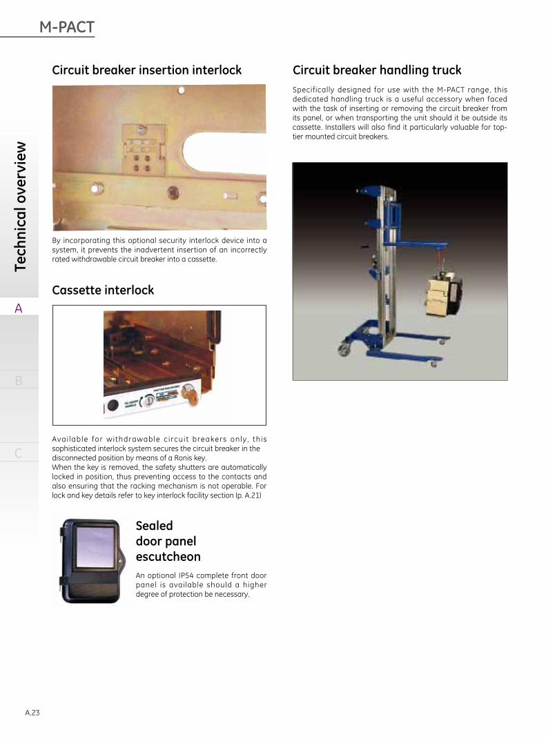
Circuit breaker insertion interlock Circuit breaker handling truck
Cassette interlock
Sealeddoor panelescutcheonAn optional IP54 complete front door panel is available should a higher degree of protection be necessary.
By incorporating this optional security interlock device into a system, it prevents the inadvertent insertion of an incorrectly rated withdrawable circuit breaker into a cassette.
Avai lable for withdrawable c i rcuit breakers only , th is sophisticated interlock system secures the circuit breaker in thedisconnected position by means of a Ronis key.When the key is removed, the safety shutters are automatically locked in position, thus preventing access to the contacts and also ensuring that the racking mechanism is not operable. For lock and key details refer to key interlock facility section (p. A.21)
Specifically designed for use with the M-PACT range, this dedicated handling truck is a useful accessory when faced with the task of inserting or removing the circuit breaker from its panel, or when transporting the unit should it be outside its cassette. Installers will also find it particularly valuable for top-tier mounted circuit breakers.

A
B
C
A.24
Accessories Performance Data
DeviceOperating Voltage (V) Rating
(Amps resistive)AC DC Operating range
Auxiliary & carriage switch250 - 10
125 - 5250 - 0.25
Motor operator
220-250 220-250AC-50VADC-50W
110-130 110-130380-440 48, 60 0.85 to 1.1 times
24-30 rated voltage
Closing coil
220-250 220-250AC-300VADC-250W
110-130 110-130380-440 48 0.85 to 1.1 times
24-30 rated voltage
Shunt trip
220-250 220-250AC-300VADC-250W
110-130 110-130380-440 48 0.70 to 1.1 times
24-30 rated voltage
Instantanious Undervoltage release
380-440 110-130 -Inrush power consumption 300VAHolding power consumption 20VA220-250 48 -
110-130 24-30 -Auxiliary power unit 110, 220, 380 110, 220 - -
Plug-in Portable Test Unit (PTU) Auxiliary Power Unit (APU)
Specially designed for reliable testing of the MCR and HSISCprotection systems on each phase, by means of tertiaryinjection. Can be powered by 2 x 9 V batteries or main power lead. Available to be fitted within the circuit breaker cubicle, an
APU ensures that M-PRO receives independent and continuouspower at all times. The APU accepts any input supplyvoltage within 380VAC, 110V, 220V AC/DC. Maximuminput current is 0.5 A. 1m length cable (twisted pair) shouldbe used to connect auxiliary supply and MPRO protectionrelay.
M-PACT Accessories

M-PACT
A
B
C
Ord
er c
odes
B.1
Technical overview
Order codes
Wiring diagramsDimensional drawings
B.2 Specify on the orderB.3 Breaker ordering codeB.5 M-PACT Air Circuit Breaker - Type A - 50kAB.7 M-PACT Air Circuit Breaker - Type D - 65kAB.9 M-PACT Air Circuit Breaker - Type H1,H2 - 80kAB.11 Factory Mounted Trip UnitsB.12 Spare Trip Units

A
B
C
B.2
1. Customer Name 2. Project Name 3. Quanitity
Specify on the Order
Code MP □ □ □ □ □ □ -□ □ □ □ □ □ □ □ Voltage (Ue) □ 415V □ 690V
1. Device □ TypeA 50kA □ TypeD 65kA □ TypeH1 80kA □ TypeH2 80kA
2. Rating □ 400A □ 630A □ 800A □ 1000A □ 1250A □ 1600A
□ 2000A □ 2500A □ 3200A □ 4000A
3. Number of Poles □ 3 Pole □ 4Pole Left Neutral □ 4Pole Right Neutral * Viewed from front of breaker.
4. System □ 3 phase 3 wire □ 3 phase 4 wire
5. Frequency □ 50Hz □ 60Hz
6. Type Connections Top&Bottom
□ Fix □ Front □ Horizontal □ Vertical
□ Withdrawable □ Front □ Horizontal □ Vertical
□ Moving portion only
□ Cassette only □ Front □ Horizontal □ Vertical
7. Protection □ Non automatic □ MPRO 27 □ MPRO 27 WITH GF □ MPRO 50L □ MPRO 50H
8. Optional Features□ Mechanical Operation Counter □ Mechanical Trip Alarm Switch (1NO)□ Portable Test Unit Auxillary Power Unit □ 110V AC/DC □ 220V AC/DC Auxillary Contactor □ 5NC+3NC □ 4NC+4NC
9. Control Voltage MOP CC ST UV UVTD
24/30V DC □ □ □
48V DC □ □ □ □ □
60V DC □
110/130V DC □ □ □ □
110/130V AC □ □ □ □
220/250V DC □ □ □
220/250V AC □ □ □ □ □
380/440V AC □ □ □ □ □
Charging contact signal is default with charging motor
10. Carriage switch □ Factory fitted □ Loose kit
11. Interlocks Door interlock □ left Door interlock (Hinge in left) □ Right door interlock(Hinge in right)
□ Ronis Cassette Key interlock
□ Ronis Breaker Key interlock □ Lock A □ Lock B □ Lock C □ Lock D
□ Circuit breaker misinsertion interlock
Cable Interlock □ Type A 2 way □ Type B 1 from 3 way
□ Type C 2 from 3 way
Cable Length required (in centimeters)
□ 160 □ 200 □ 300
12. Miscellaneous □ IP54 Door panel □ ACB Lifting Truck
13. Special requirements (please Specify any improtant instructions)
Specify on the Order

M-PACT
A
B
C
Ord
er c
odes
B.3
M P A 3 1 F 0 8
A 50kA
D 65kA
H 80kA
H2 80kA
F Fixed
W Withdrawable
M Cassette
C Moving Part
08 800A
10 1000A
12 1250A
16 1600A
20 2000A
25 2500A
32 3200A
40 4000A
000 standard without any option002 Earth Fault Protection(UEF)006 Neutral protection015 Ronis Key breaker Interlock (factory fitted)016 Mechanical Trip alarm Switch (1n/o)049 Carriage switch025 UEF+Mechanical Trip alarm Switch (1n/o)+Ronis Key breaker Interlock (factory fitted)028 Mechanical Trip alarm Switch (1n/o) + Carriage switch +UEF029 Ronis Key breaker Interlock (factory fitted)+UEF047 UEF+Mechanical Trip alarm Switch (1n/o)+Mechanical operations counter104 UEF+Mechanical Trip alarm Switch (1n/o)+Carriage switch107 UEF+Mechanical Trip alarm Switch (1n/o)111 Mechanical Trip alarm Switch (1n/o)+Ronis Key breaker Interlock
3 3 poles
4 4 poles
1 Frame 1
2 Frame 2Breaking Capacity
others Acc
For more option codes please ref to sheet "optional" or contact our local office.
Poles
Frame
Type
Rating
Breaker ordering code

A
B
C
B.4
Breaker ordering code
N 4 4 4 0 X X X
0 No
1 24/30V DC
2 48V DC
3 110/130V DC/AC
4 220/250V DC/AC
5 380/400V AC
0 No
1 48V DC
2 110/130V AC
3 220/250V AC
4 380/440V AC
5 30/48V DC - delay
6 220/250V AC - delay
7 380/440V AC - delay
0 No
1 24/30V DC
2 48V DC
3 110/130V DC/AC
4 220/250V DC/AC
others Acc
0 No
1 24/30V DC
2 48V DC
3 110/130V DC/AC
4 220/250V DC/AC
0 Non-Auto
N Mpro 27
V Mpro50L
W Mpro50H
MPro Shunt
Undervoltage
Motor Operator
Closing coil
Note: The following parts are supplied default with the breaker1. Auxiliary power supply of 24V DC2. IP30 Door flange3. Connection bars are default with drawout breaker.4. Auxilary contacts 5NC + 3NO5. The 4th RC sensor with 3P breaker & GF option6. Saftey shutter

M-PACT
A
B
C
Ord
er c
odes
B.5
M-PACT Air Circuit Breaker - TYPE A - 50kA
Basic circuit breaker manually operated, 5 NO and 3 NC auxiliary switches.Withdrawable pattern - basic circuit breaker and cassette with flat copper terminalsrear connected.Fixed pattern - basic circuit breaker with rear terminals horizontal.
Withdrawable and Fixed PatternWithdrawable Fixed Pattern
Frame size Rating (A) Poles Cat. no. Cat. no.1 400 3 MPA31W04 MPA31F04
4 MPA41W04 MPA41F041 800 3 MPA31W08 MPA31F08
4 MPA41W08 MPA41F081 1000 3 MPA31W10 MPA31F10
4 MPA41W10 MPA41F101 1250 3 MPA31W12 MPA31F12
4 MPA41W12 MPA41F121 1600 3 MPA31W16 MPA31F16
4 MPA41W16 MPA41F161 2000 3 MPA31W20 MPA31F20
4 MPA41W20 MPA41F201 2500 3 MPA31W25 MPA31F25
4 MPA41W25 MPA41F252 3200 3 MPA32W32 MPA32F32
4 MPA42W32 MPA42F322 4000 3 MPA32W40 MPA32F40
4 MPA42W40 MPA42F40
Front Access ConnectionsWithdrawable
TOP connections BOTTOM connectionsFrame size Rating (A) Poles Cat. no. Cat. no.
1 400 to 1600 3 FA31WA16T FA31WA16B4 FA41WA16T FA41WA16B
1 2000 to 2500 3 FA31WA25T FA31WA25B4 FA41WA25T FA41WA25B
2 3200 3 FA32WA32T FA32WA32B4 FA42WA32T FA42WA32B
2 4000 3 FA32WA40T FA32WA40B4 FA42WA40T FA42WA40B
Rear 'T' Connections (for cassette only)Pequired QuantityFrame size Rating (A) Poles Cat. no. Cat. no.
1 400 to 1600 3 6 RT1HOR Horizontal4 8 RT1HOR Horizontal
1 400 to 1600 3 6 RT1VER Vertical4 8 RT1VER Vertical
1 2000 & 2500 3 6 RT1UNI Universal4 8 RT1UNI Universal
2 3200 3 6 RT2UNI Universal4 8 RT2UNI Universal
2 4000 3 Standard N/A Vertical4 Standard N/A Vertical
Installation: Units rated < 1600A have reduced copper section.Refer to engineered drawings in section C.

A
B
C
B.6
Front Access ConnectionsFixed Type
TOP connections BOTTOM connectionsFrame size Rating (A) Poles Cat. no. Cat. no.
1 400 to 1600 3 FA31FA16T FA31FA16B4 FA41FA16T FA41FA16B
1 2000 to 2500 3 FA31FA25T FA31FA25B4 FA41FA25T FA41FA25B
2 3200 3 FA32FA32T FA32FA32B4 FA42FA32T FA42FA32B
2 4000 3 FA32FA40T FA32FA40B4 FA42FA40T FA42FA40B
Cassette onlyBasic cassette with flat copper terminals rear connected.
Frame size Rating (A) Poles Cat. no.1 400 to 1600 3 MPA31C16
4 MPA41C161 2000 to 2500 3 MPA31C25
4 MPA41C252 3200 3 MPA32C32
4 MPA42C322 4000 3 MPA32C40
4 MPA42C40
Moving Portion onlyBasic circuit breaker manually operated,5 NO and 3 NC auxiliary switches and cluster contacts.
Frame size Rating (A) Poles Cat. no.1 400 3 MPA31M04
4 MPA41M041 800 3 MPA31M08
4 MPA41M081 1000 3 MPA31M10
4 MPA41M101 1250 3 MPA31M12
4 MPA41M121 1600 3 MPA31M16
4 MPA41M161 2000 3 MPA31M20
4 MPA41M201 2500 3 MPA31M25
4 MPA41M252 3200 3 MPA32M32
4 MPA42M322 4000 3 MPA32M40
4 MPA42M40
Air Circuit Breaker - TYPE A - 50kA
M-PACT
A
B
C
Ord
er c
odes
B.7
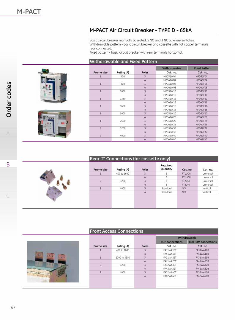
M-PACT Air Circuit Breaker - TYPE D - 65kA
Basic circuit breaker manually operated, 5 NO and 3 NC auxiliary switches.Withdrawable pattern - basic circuit breaker and cassette with flat copper terminals rear connected.Fixed pattern - basic circuit breaker with rear terminals horizontal.
Withdrawable and Fixed PatternWithdrawable Fixed Pattern
Frame size Rating (A) Poles Cat. no. Cat. no.1 400 3 MPD31W04 MPD31F04
4 MPD41W04 MPD41F041 800 3 MPD31W08 MPD31F08
4 MPD41W08 MPD41F081 1000 3 MPD31W10 MPD31F10
4 MPD41W10 MPD41F101 1250 3 MPD31W12 MPD31F12
4 MPD41W12 MPD41F121 1600 3 MPD31W16 MPD31F16
4 MPD41W16 MPD41F161 2000 3 MPD31W20 MPD31F20
4 MPD41W20 MPD41F201 2500 3 MPD31W25 MPD31F25
4 MPD41W25 MPD41F252 3200 3 MPD32W32 MPD32F32
4 MPD42W32 MPD42F322 4000 3 MPD32W40 MPD32F40
4 MPD42W40 MPD42F40
Front Access ConnectionsWithdrawable
TOP connections BOTTOM connectionsFrame size Rating (A) Poles Cat. no. Cat. no.
1 400 to 1600 3 FA31WA16T FA31WA16B4 FA41WA16T FA41WA16B
1 2000 to 2500 3 FA31WA25T FA31WA25B4 FA41WA25T FA41WA25B
2 3200 3 FA32WA32T FA32WA32B4 FA42WA32T FA42WA32B
2 4000 3 FA32WA40T FA32WA40B4 FA42WA40T FA42WA40B
Rear 'T' Connections (for cassette only)Pequired QuantityFrame size Rating (A) Poles Cat. no. Cat. no.
1 400 to 1600 3 6 RT1UOR Universal4 8 RT1UOR Universal
2 3200 3 6 RT2UNI Universal4 8 RT2UNI Universal
2 4000 3 Standard N/A Vertical4 Standard N/A Vertical

A
B
C
B.8
Front Access ConnectionsFixed Type
TOP connections BOTTOM connectionsFrame size Rating (A) Poles Cat. no. Cat. no.
1 400 to 1600 3 FA31FD16T FA31FD16B4 FA41FD16T FA41FD16B
1 2000 to 2500 3 FA31FD25T FA31FD25B4 FA41FD25T FA41FD25B
2 3200 3 FA32FD32T FA32FD32B4 FA42FD32T FA42FD32B
2 4000 3 FA32FD40T FA32FD40B4 FA42FD40T FA42FD40B
Cassette onlyBasic cassette with flat copper terminals rear connected.
Frame size Rating (A) Poles Cat. no.1 400 to 1600 3 MPD31C25
4 MPD41C252 3200 3 MPD32C32
4 MPD42C322 4000 3 MPD32C40
4 MPD42C40
Moving Portion onlyBasic circuit breaker manually operated,5 NO and 3 NC auxiliary switches and cluster contacts.
Frame size Rating (A) Poles Cat. no.1 400 3 MPD31M04
4 MPD41M041 800 3 MPD31M08
4 MPD41M081 1000 3 MPD31M10
4 MPD41M101 1250 3 MPD31M12
4 MPD41M121 1600 3 MPD31M16
4 MPD41M161 2000 3 MPD31M20
4 MPD41M201 2500 3 MPD31M25
4 MPD41M252 3200 3 MPD32M32
4 MPD42M322 4000 3 MPD32M40
4 MPD42M40
Air Circuit Breaker - TYPE D - 65kA

M-PACT
A
B
C
Ord
er c
odes
B.9
M-PACT Air Circuit Breaker - TYPE H1,H2 - 80kABasic circuit breaker manually operated, 5 NO and 3 NC auxiliary switches.Withdrawable pattern - basic circuit breaker and cassette with flat copper terminalsrear connected.Fixed pattern - basic circuit breaker with rear terminals horizontal.
Withdrawable and Fixed PatternFrame
size Rating (A) PolesWithdrawable Fixed Pattern Withdrawable Fixed Pattern
Cat. no. Cat. no. Cat. no. Cat. no.2 800 3 MPH32W08 MPH32F08 MPH232W08 MPH232F08
4 MPH42W08 MPH42F08 MPH242W08 MPH242F08
2 1000 3 MPH32W10 MPH32F10 MPH232W10 MPH232F10
4 MPH42W10 MPH42F10 MPH242W10 MPH242F10
2 1250 3 MPH42W12 MPH32F12 MPH232W12 MPH232F12
4 MPH42W12 MPH42F12 MPH242W12 MPH242F12
2 1600 3 MPH32W16 MPH32F16 MPH232W16 MPH232F16
4 MPH42W16 MPH42F16 MPH242W16 MPH242F16
2 2000 3 MPH32W20 MPH32F20 MPH232W20 MPH232F20
4 MPH42W20 MPH42F20 MPH242W20 MPH242F20
2 2500 3 MPH32W25 MPH32F25 MPH232W25 MPH232F25
4 MPH42W25 MPH42F25 MPH242W25 MPH242F25
2 3200 3 MPH32W32 MPH32F32 MPH232W32 MPH232F32
4 MPH42W32 MPH42F32 MPH242W32 MPH242F32
2 4000 3 MPH32W40 MPH32F40 MPH232W40 MPH232F40
4 MPH42W40 MPH42F40 MPH242W40 MPH242F40
Front Access ConnectionsWithdrawable
TOP connections BOTTOM connectionsFrame size Rating (A) Poles Cat. no. Cat. no.
2 800 - 3200 3 FA42WH32T FA32WH32B
4 FA42WH32T FA42WH32B
2 4000 3 FA32WH40T FA42WH40B
4 FA42WH40T FA42WH40B
Front Access ConnectionsFixed Type
TOP connections BOTTOM connectionsFrame size Rating (A) Poles Cat. no. Cat. no.
2 800 - 3200 3 FA32FH32T FA32FH32B
4 FA42FH32T FA42FH32B
2 4000 3 FA32FH40T FA32FH40B
4 FA42FH40T FA42FH40B
Rear 'T' Connections (for cassette only)Frame
size Rating (A) Poles RequiredQuantity Cat. no.
2 800 - 3200 3 6 RT2UNI
4 8 RT2UNI
2 4000 3 Standard N/A
4 Standard N/A

A
B
C
B.10
Cassette onlyBasic cassette with flat copper terminals rear connected.
Frame size Rating (A) Poles Cat. no.2 800 - 3200 3 MPH32C32
4 MPH42C32
2 4000 3 MPH32C40
4 MPH42C40
Moving Portion onlyBasic circuit breaker manually operated,5 NO and 3 NC auxiliary switches and cluster contacts.
Frame size Rating (A) Poles Cat. no. Cat. no.2 800 3 MPH32M08 MPH232M08
4 MPH42M08 MPH242M08
2 1000 3 MPH32M10 MPH232M10
4 MPH42M10 MPH242M10
2 1250 3 MPH32M12 MPH232M12
4 MPH42M12 MPH242M12
2 1600 3 MPH32M16 MPH232M16
4 MPH42M16 MPH242M16
2 2000 3 MPH32M20 MPH232M20
4 MPH42M20 MPH242M20
2 2500 3 MPH32M25 MPH232M25
4 MPH42M25 MPH242M25
2 3200 3 MPH32M32 MPH232M32
4 MPH42M32 MPH242M32
2 4000 3 MPH32M40 MPH232M40
4 MPH42M40 MPH242M40
Air Circuit Breaker - TYPE H1 ,H
2 - 80kA

M-PACT
A
B
C
Ord
er c
odes
B.11
MPRO-50L For Frame 1 GH100M7-6SFLT band choice (LT-C or LT-F)
LT-C 0.4-1 x In = Ir Dual GF protection (Res./SUM or CT)-ORLT- Relt Instantaneous &F 0.4-1 x In = Ir Modbus CommunictionSTSTDGF sum. I2t ON or OFF For Frame 2 GH200M7-6SF-AND/ORGF LT band choice (LT-C or LT-F)CR I2t ON or OFF Dual GF protection (Res./SUM or CT)GFDB Relt Instantaneous & I Modbus CommunictionRELTInput supply 24V AC(1)
MPRO-50H For Frame 1 GQ100M7-6SFLT band choice (LT-C or LT-F)
LT-C 0.4-1 x In = Ir Dual GF protection (Res./SUM or CT)-ORLT- Relt Instantaneous &F 0.4-1 x In = Ir Modbus CommunictionSTSTDGF sum. I2t ON or OFF For Frame 2 GQ200M7-6SF-AND/ORGF LT band choice (LT-C or LT-F)CR I2t ON or OFF Dual GF protection (Res./SUM or CT)GFDB Relt Instantaneous &I Modbus CommunictionRELTInput supply 110-130V DCor 110-250V AC(1)
Factory Mounted Trip Units
MPRO-27
MPRO-50
Accessories
Functionality and application Cat. No.MPRO-27 trip unit For Frame 1 GL100M3-SF
LT-C 0.4-1 x In = Ir For Frame 2 GL200M3-SFLTDBST I2t ON or OFFSTDB
MPRO-27 trip unit For Frame 1 GL100M5-SF
LT-C 0.4-1 x In = Ir For Frame 2 GL200M5-SFLTDBST I2t ON or OFFSTDBGF sum. I2t ON or OFFGFDB
Basic functionality
Basic functionality
Extended functionality
Extended functionality
Designation
Digital test kit GTUTK20
(1) relay output available voltage rate.MPRO50L= 24V AC,MPRO50H=110-250V ACThe MPRO27/50 trip units are not offered individually, they must be order with a complete breaker.For spares and service purposes, please contact your local GE Energy Industrial Solutions service department you will be required to provide a valid serial number.

A
B
C
B.12
Spare Trip Units
Withdrawable and Fixed PatternRange Voltage Cat. no. Order Code
Shunt trip (ST) 24/30 V DC ST30 B4000655448 V DC ST48 B40006555
110/130 V AC/DC ST130 B40006401220/250 V AC/DC ST250 B40006500380/440 V AC ST440 B40006497
Motor operator (MOP) 24/30 V DC MOP30 B4002960048 V DC MOP48 B40029601
110/130 V AC/DC MOP130 B40033630220/250 V AC/DC MOP250 B40032398380/440 V AC MOP440A B90000018
Closing coil (CC) 24/30 V DC CC30 B4000655648 V DC CC48 B40006557
110/130 V AC/DC CC130 B40006402220/250 V AC/DC CC250 B40006498300/440 V AC CC440 B90000018
Undervoltage release (UV) 48 V DC UV48 B40027558110/130 V AC UV130A B40027559110/130 V DC UV130D B40027570220/250 V AC UV250 B40033628380/440 V AC UV440 B40006578
Undervoltage release time delayed (UVTD) 48 V DC UVTD48 B40027571
The UVTD already involved UV and time delay relay.
220/250 V AC UVTD250 B40006576380/440 V AC UVTD440 B40006580
250 V AC/DC CSWFF B40011377Spring charged signal (1 x N/O) SCC
Offered with spring charging motor
Mechanical Accessories2 way Interlocking Type A 1 from 3 wayInterlocking Type B
Framesize
Type Poles Cable Framesize
Type Poles CableCat. no. Ref. no. Cat. no. Ref. no.
1 Withdrawable 3 2WCI3PW 406342 1 Withdrawable 3 B13WCI3PW 4063501 4 2WCI4PW 406343 1 4 B13WCI4PW 4063512 3 2WCI3PW 405459 2 3 B13WCIF23PW 4054752 4 2WCI4PW 405461 2 4 B13WCIF24PW 4054771 Fixed 3 2WCI3PF 406340 1 Fixed 3 B13WCI3PF 4063481 4 2WCI4PF 406341 1 4 B13WCI4PF 4063492 3 2WCI3PF 405463 2 3 B13WCIF23PF 4054792 4 2WCI4PF 405465 2 4 B13WCIF24PF 405481
Cable for interlocksItem Cat. no. Ref. no.
cable, 100cm 100BCMCI 405531cable, 160cm 160BCMCI 405532cable, 200cm 200BCMCI 405533cable, 300cm 300BCMCI 405611
2 from 3 way Interlocking Type CFrame
sizeType Poles Cable
Cat. no. Ref. no.1 Withdrawable 3 C23WCI3PW 4063581 4 C23WCI4PW 4063592 3 C23WCIF23PW 4054912 4 C23WCIF24PW 4054931 Fixed 3 C23WCI3PF 4063561 4 C23WCI4PF 4063572 3 C23WCIF23PF 4054952 4 C23WCIF24PF 405497
Please refer to page A.23 for available cable configurations.
Longer length required , contact local GE Office please.
Spare Trip Units

M-PACT
A
B
C
Ord
er c
odes
B.13
Spare parts
Current transformer with mounting kit(1) Neutral (4th) Rogowski coilwith mounting kit(2)
Current transformer Rogowski coil(2)
Frame size Rating (A) Cat. No. Order Code Cat. No. Order Code
1 800 ELCT8001 RCMK80012 ELCT8002 RCMK80021 1000 ELCT10001 RCMK100012 ELCT10002 RCMK100021 1250 ELCT12501 RCMK125012 ELCT12502 RCMK125021 1600 ELCT16001 RCMK160012 ELCT16002 RCMK160021 2000 ELCT20001 RCMK200012 ELCT20002 RCMK200021 2500 ELCT25001 RCMK250012 ELCT25002 RCMK250022 3200 ELCT32002 RCMK320022 4000 ELCT40002 RCMK40002
Interlocks MiscellaneousItem Cat. no. Order Code Item Cat. no. Order Code
Mechanical Operations Counter MOC B40006511left Door interlock (Hinge in left) DILHS B40006546
Ronis Key breaker Interlock⑴ RONLOK B40006515 Right door interlock(Hinge in right) DIRHS B40006504Ronis Key Cassette Interlock(factory fitted) RONCASFF B40011378 Mis-Insertion Device ACBMID B40006503
IP54 Door IP54DOOR B40006507Lifting Truck ACBLIFT B40006832Mechanical Trip Alarm Switch MPROMAC B40006573
(1) The earth CT leg is used for GF CT function which offered by MPOR50. But it is not default with MPOR50 as standard parts. Please contact with GE local office,if you have any inquire.
(2) Rogowski coils are provided with twisted pair cables of (max. length 2m). The 4th Rogowski coil for GF protection comes default with 3 pole breakers. If you need a separate 4th Rogowski coil please
contact your local GE Energy Industrial Solutions office.
Frame 1, 2
(1) There are 4 lock type available (A, B, C, D). Please put A, B, C, D back on B40006515 when you order Ronis individually.
A
B
C
C.1
Technical overview
Air circuit breakers 400A-4000A
Order codes
Wiring DiagramsDimensional drawings
C.2 Mpro 27 & 50 Connection SchemeC.6 Dimensional drawings

M-PACT
A
B
C
Wir
ing
diag
ram
sD
imen
sion
al d
raw
ings
C.2
Connection scheme
N-RC
A9 A8
N-RC- +
N
B 5 B 6
24V+ 24V-
+24-VDC
Electronic Trip Unit MPRO 27
Connection scheme
Relay O/P2
A 6 A 5
Relay O/P1
A 8 A 7
Electronic Trip Unit MPRO 50
N-RC
A15 A14
N-RC- +
N
Relay O/P3 Relay O/P4
A 2 A 1A 4 A 3 B 5 B 6
24V+ 24V-
+24-VDC
EL CT
B 3 B 4
Interposing CT
A12 A11 A10 A 9
1 2 3 4
Input 1 - 4
A13
C
A20 A19
RX- RX+
Communication
A16
SCR
A18 A17
TX- TX+
N
Breaker accessories
OFF ONOFF
C15
AAAAABBBAA
C
D
MLAL
M ST CC UVRUVTD
C13
C11
C9C7C5C3C1
B15
B13
(+VE)(-VE)
B11
C16
C14
C12
C10
LP6
LP5
LP7
C8C6C4C2
B16
B14
(-VE)
B12
B10
B8
LP4
B9B7
(+VE)
B1B2
Mpro 27 & 50 Connection Scheme
Wiring Diagrams

A
B
C
C.3
Dimensional drawings
Horizontal, rear access connectionFixed patternType A-3 pole- Frame size 1, In=400A to 1600A
Type A-4 pole- Frame size 1, In=400A to 1600A
100 to door
100 to door
Centre line of operating panel
Centre line of operating panel
Centre line ofoperating panel
Centre line ofoperating panel
Copperwork must be supported within 200 mm of breakerconnections-busbars or cables. All connections to be tightened to 50Nm.
Copperwork must be supported within 200 mm of breakerconnections-busbars or cables. All connections to be tightened to 50Nm.
Minimum space to earth metaland for arc chute removal
Minimum space to earth metaland for arc chute removal
Insulated metal or insulatedsheet ( customer supplied )
Insulated metal or insulatedsheet ( customer supplied )
Dim
ensional drawings
Mounting hole - Fixed TypeFrame 1 - ¢ 9.2mm , Recommend bolt M8 x 4.Frame 2 - ¢ 11.2mm , Recommend bolt M10 x 4.

M-PACT
A
B
C
Wir
ing
diag
ram
sD
imen
sion
al d
raw
ings
C.4
Horizontal, rear access connectionFixed patternType D-3 pole- Frame size 1, In=400A to 1600A
100 to door
100 to door
Centre line of operating panel
Centre line of operating panel
Centre line ofoperating panel
Centre line ofoperating panel
Copperwork must be supported within 200 mm of breakerconnections-busbars or cables. All connections to be tightened to 50Nm.
Copperwork must be supported within 200 mm of breakerconnections-busbars or cables. All connections to be tightened to 50Nm.
Minimum space to earth metaland for arc chute removal
Minimum space to earth metaland for arc chute removal
Insulated metal or insulatedsheet ( customer supplied )
Insulated metal or insulatedsheet ( customer supplied )
Type D-4 pole- Frame size 1, In=400A to 1600A

A
B
C
C.5
100 to door
100 to door
Horizontal, rear access connectionFixed patternType A, D-3 pole- Frame size 1, In=2000A to 2500A
Centre line of operating panel
Centre line of operating panel
Centre line ofoperating panel
Centre line ofoperating panel
Copperwork must be supported within 200 mm of breakerconnections-busbars or cables. All connections to be tightened to 50Nm.
Copperwork must be supported within 200 mm of breakerconnections-busbars or cables. All connections to be tightened to 50Nm.
Minimum space to earth metaland for arc chute removal
Minimum space to earth metaland for arc chute removal
Insulated metal or insulatedsheet ( customer supplied )
Insulated metal or insulatedsheet ( customer supplied )
Type A, D-4 pole- Frame size 1, In=2000A to 2500A
Dim
ensional drawings

M-PACT
A
B
C
Wir
ing
diag
ram
sD
imen
sion
al d
raw
ings
C.6
Horizontal, rear access connectionFixed patternType A, D-3 pole- Frame size 2, In=3200A to 4000AType H-3 pole- Frame size 2, In=800A to 4000A
100 to door
100 to door
Centre line of operating panel
Centre line of operating panel
Centre line ofoperating panel
Centre line ofoperating panel
Copperwork must be supported within 200 mm of breakerconnections-busbars or cables. All connections to be tightened to 50Nm.
Copperwork must be supported within 200 mm of breakerconnections-busbars or cables. All connections to be tightened to 50Nm.
Minimum space to earth metaland for arc chute removal
Minimum space to earth metaland for arc chute removal
Insulated metal or insulatedsheet ( customer supplied )
Insulated metal or insulatedsheet ( customer supplied )
Type A, D-4 pole- Frame size 2, In=3200A to 4000AType H-4 pole- Frame size 2, In=800A to 4000A

A
B
C
C.7
Rear access connectionWithdrawable patternType A-3 pole- Frame size 1, In=400A to 1600A
Copperwork must be supported within 200 mm of breakerconnections-busbars or cables. All connections to be tightened to 50Nm.
Copperwork must be supported within 200 mm of breakerconnections-busbars or cables. All connections to be tightened to 50Nm.
Centre line of operating panel
Centre line of operating panel
35 Test50 Disconnected
275 Fully withdrawn
Connected
Ventilation
Minimum clearanceto cassette side
Centre line of operating panel
Centre line of operating panel
35 Test50 Disconnected
275 Fully withdrawn
Connected
Ventilation
Minimum clearanceto cassette side
to door
to door
Type A-4 pole- Frame size 1, In=400A to 1600A
Dim
ensional drawings

M-PACT
A
B
C
Wir
ing
diag
ram
sD
imen
sion
al d
raw
ings
C.8
Rear access connectionWithdrawable patternType A-3 pole- Frame size 1, In=2000A & 2500AType D-3 pole- Frame size 1, In=400A to 2500A
Type A-4 pole- Frame size 1, In=2000A & 2500AType D-4 pole- Frame size 1, In=400A to 2500A
Copperwork must be supported within 200 mm of breakerconnections-busbars or cables. All connections to be tightened to 50Nm.
Copperwork must be supported within 200 mm of breakerconnections-busbars or cables. All connections to be tightened to 50Nm.
Centre line of operating panel
Centre line of operating panel
35 Test
50 Disconnected
275 Fully withdrawn
Connected
Ventilation
Minimum clearanceto cassette side
Centre line of operating panel
Centre line of operating panel
35 Test
50 Disconnected275 Fully withdrawn
Connected
Ventilation
Minimum clearanceto cassette side
to door
to door

A
B
C
C.9
Rear access connectionWithdrawable patternType A, D-3 pole- Frame size 2, In=3200AType H-3 pole- Frame size 2, In=800A to 3200A
Type A, D-4 pole- Frame size 2, In=3200AType H-4 pole- Frame size 2, In=800A to 3200A
Copperwork must be supported within 200 mm of breakerconnections-busbars or cables. All connections to be tightened to 50Nm.
Copperwork must be supported within 200 mm of breakerconnections-busbars or cables. All connections to be tightened to 50Nm.
to door
to door
Center line ofoperating panel
Center line ofoperating panel
Center line ofoperating panel
Center line ofoperating panel
50 Disconnected35 Test
275 Fully withdrawn
50 Disconnected35 Test
275 Fully withdrawn
Connected
Connected
Vent
ilatio
n
Ventilation
Minimum clearance to cassette side
Minimum clearance to cassette side
Dim
ensional drawings

M-PACT
A
B
C
Wir
ing
diag
ram
sD
imen
sion
al d
raw
ings
C.10
Rear access connectionWithdrawable pattern
Type A, D,H - 3 pole - Frame size 2, ln=4000A
Type A, D,H - 4 pole - Frame size 2, ln=4000A
Must not be removedor fitted horizontally
Must not be removedor fitted horizontally
Center line ofoperating panel
Center line ofoperating panel
Center line ofoperating panel
Center line ofoperating panel 50 Disconnected
35 Test
275 Fully withdrawn
50 Disconnected35 Test
275 Fully withdrawn
Connected
Connected
to d
oor
to d
oor Ventilation
Vent
ilatio
n
Minimum clearance to cassette side
Minimum clearance to cassette side
Copperwork must be supported within 200 mm of breakerconnections-busbars or cables. All connections to be tightened to 50Nm.
Copperwork must be supported within 200 mm of breakerconnections-busbars or cables. All connections to be tightened to 50Nm.

A
B
C
C.11
Front access connectionFixed pattern
Type A, D - 3 pole - Frame size 1, ln = 400A to 1600A
Type A, D - 4 pole - Frame size 1, ln = 400A to 1600A
Center line ofoperating panel
Center line ofoperating panel
Center line ofoperating panel
Center line ofoperating panel
Insulated metalor insulated sheet(customer supplied)
Insulated metalor insulated sheet(customer supplied)
Minimum space to earth metaland for arc chute removal
Minimum space to earth metaland for arc chute removal
100 to door
100 to door
Minimum clearance to breaker side
Minimum clearance to breaker side
Copperwork must be supported within 200 mm of breakerconnections-busbars or cables. All connections to be tightened to 50Nm.
Copperwork must be supported within 200 mm of breakerconnections-busbars or cables. All connections to be tightened to 50Nm.
Dim
ensional drawings

M-PACT
A
B
C
Wir
ing
diag
ram
sD
imen
sion
al d
raw
ings
C.12
Front access connectionFixed pattern
Type A, D - 3 pole - Frame size 1, ln = 2000A to 2500A
Type A, D - 4 pole - Frame size 1, ln = 2000A to 2500A
Insulated metalor insulated sheet(customer supplied)
Minimum space to earth metaland for arc chute removal
100 to door
Insulated metalor insulated sheet(customer supplied)
Minimum space to earth metaland for arc chute removal
100 to door
Center line ofoperating panel
Center line ofoperating panel
Center line ofoperating panel
Center line ofoperating panel
Minimum clearance to breaker side
Minimum clearance to breaker side
Copperwork must be supported within 200 mm of breakerconnections-busbars or cables. All connections to be tightened to 50Nm.
Copperwork must be supported within 200 mm of breakerconnections-busbars or cables. All connections to be tightened to 50Nm.
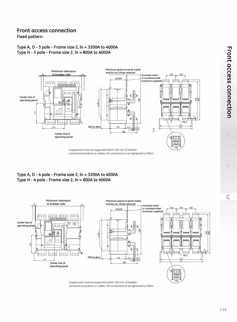
A
B
C
C.13
Front access connectionFixed pattern
Type A, D - 3 pole - Frame size 2, ln = 3200A to 4000AType H - 3 pole - Frame size 2, ln = 800A to 4000A
Type A, D - 4 pole - Frame size 2, ln = 3200A to 4000AType H - 4 pole - Frame size 2, ln = 800A to 4000A
Insulated metalor insulated sheet(customer supplied)
Minimum space to earth metaland for arc chute removal
100 to door
Insulated metalor insulated sheet(customer supplied)
Minimum space to earth metaland for arc chute removal
100 to door
Center line ofoperating panel
Center line ofoperating panel
Center line ofoperating panel
Center line ofoperating panel
Minimum clearance to breaker side
Minimum clearance to breaker side
Copperwork must be supported within 200 mm of breakerconnections-busbars or cables. All connections to be tightened to 50Nm.
Copperwork must be supported within 200 mm of breakerconnections-busbars or cables. All connections to be tightened to 50Nm.
Front access connection

M-PACT
A
B
C
Wir
ing
diag
ram
sD
imen
sion
al d
raw
ings
C.14
Center line ofoperating panel
Center line ofoperating panel
Minimum clearance to cassette side
Connected
Connected
Disconnected
Disconnected
Test
Test
to d
oor
to d
oor
Copperwork must be supported within 200 mm of breakerconnections-busbars or cables. All connections to be tightened to 50Nm.
Copperwork must be supported within 200 mm of breakerconnections-busbars or cables. All connections to be tightened to 50Nm.
Front access connectionWithdrawable pattern
Type A, D - 3 pole - Frame size 1, ln = 400A to 1600A
Type A, D - 4 pole - Frame size 1, ln = 400A to 1600A

A
B
C
C.15
Front access connectionWithdrawable pattern
Type A, D - 3 pole - Frame size 1, ln = 2000A to 2500A
Type A, D - 4 pole - Frame size 1, ln = 2000A to 2500A
Center line ofoperating panel
Center line ofoperating panel
Center line ofoperating panel
Center line ofoperating panel
Minimum clearance to cassette side
Minimum clearance to cassette side
Connected
Connected
Disconnected
Disconnected
Test
Test
to d
oor
to d
oor
Copperwork must be supported within 200 mm of breakerconnections-busbars or cables. All connections to be tightened to 50Nm.
Copperwork must be supported within 200 mm of breakerconnections-busbars or cables. All connections to be tightened to 50Nm.
Front access connection

M-PACT
A
B
C
Wir
ing
diag
ram
sD
imen
sion
al d
raw
ings
C.16
Front access connectionFixed pattern
Type A, D - 3 pole - Frame size 2, ln = 3200A to 4000AType H - 3 pole - Frame size 2, ln = 800A to 4000A
Type A, D - 4 pole - Frame size 2, ln = 3200A to 4000AType H - 4 pole - Frame size 2, ln = 800A to 4000A
Center line ofoperating panel
Center line ofoperating panel
Center line ofoperating panel
Center line ofoperating panel
Minimum clearance to cassette side
Minimum clearance to cassette side
Connected
Connected
DisconnectedTest
DisconnectedTest
to d
oor
to d
oor
Copperwork must be supported within 200 mm of breakerconnections-busbars or cables. All connections to be tightened to 50Nm.
Copperwork must be supported within 200 mm of breakerconnections-busbars or cables. All connections to be tightened to 50Nm.

A
B
C
C.17
Adaptor connections
Rear Adapter Vertical ConnectionType A - Frame 1 - ln = 400A to 1600A (max)
Rear Adapter Horizontal ConnectionType A - Frame 1 - ln = 400A to 1600A (max)
Type D - Frame 1 - ln = 400A to 2500A (max)
Rear Adapter Vertical / Horizontal Connection
Type A,D,H - Frame 2 - ln = 800A to3200A (max)
Front access connection

M-PACT
A
B
C
Wir
ing
diag
ram
sD
imen
sion
al d
raw
ings
C.18
Type A - Frame 1 - ln = 400A to 2500A (max)Type D - Frame 1 - ln = 400A to 2500A (max)
Type A,D - Frame 2 - ln = 3200A to 4000A (max)Type H - Frame 2 - ln = 800A to 4000A (max)
Type A,D,H - Frame 2 - ln = 4000A
Copper connections - Rear access (withdrawable)
IP54 Door (Withdrawable unit only - Frame 1&2 only)
Copper connections - Front access (Fixed and/or withdrawable)

A
B
C
C.19
Type A,D - Frame 2 - ln = 3200A to 4000A (max)Type H - Frame 2 - ln = 800A to 4000A (max)
A. recommend installtion mounting cut
Cassette mounting details
Type A,D - Frame 1 - ln = 400A to 2500A (max)
Terminals
Terminals
Ventilation in base of cassette(leave unobstructed)
Ventilation in base of cassette(leave unobstructed)
Centre line ofoperating panel
Centre line ofoperating panel
3 pole
3 pole 4 pole
4 pole3 pole
4 pole
4 pole
4 pole
3 pole
3 pole
AA
A
A
A A
A
A
Adaptor connections

M-PACT
A
B
C
Wir
ing
diag
ram
sD
imen
sion
al d
raw
ings
C.20
Door cut-outs
Fixed pattern
Withdrawable pattern
175 10040 13
281270.2
13119
5.4
358
263 5.4
175
100
378
17828
Door
ACB facia
centre line of ACB mounting hole
16 off M3 x 6 self tapping screw
16 off M3 x 6 self tapping screw
M-PACT breaker
M-PACT breaker
Frame 1 = 42.5Frame 2 = 102.5
Door
Escutcheon
Escutcheon seal
ACB facia
Door
Escutcheon
Escutcheon seal
ACB facia
benchmark of breaker left side
Frame 1: Max.2500A=40Frame 2: Max.4000A=100
benchmark of breaker button side

A
B
C
C.21
Door cut-outs
2-Way cable interlocking
Fixed pattern - Front/rear access
Withdrawable pattern - Front/rear access
Min.clearancebelowcassette
Min.clearancebelowcassette
Min.bend radius 120
Min.bend radius 120 Min.bend radius 120
Min.bend radius 120
900
Max
ver
tical
bas
e to
bas
e90
0 M
ax v
ertic
al b
ase
to b
ase
Frame 1-3P = 322Frame 1-4P = 422Frame 2-3P = 410Frame 2-4P = 540
Frame 1-3P = 329Frame 1-4P = 429Frame 2-3P = 419Frame 2-4P = 549

M-PACT
A
B
C
Wir
ing
diag
ram
sD
imen
sion
al d
raw
ings
C.22
1250 MAX
40 M
IN. C
LEAR
ENCE
BELO
W C
ASET
TE
30
55 55
F13P=329F14P=429F23P=419F24P=549
1250 MAX
5555
140
MIN
900
MAX
. VER
TICA
LBA
SETO
BAS
E
55F13P=322F14P=422F23P=410F24P=540
3-Way cable interlocking
Fixed pattern - Front/rear access
Withdrawable pattern - Front/rear access
these 2 cabel length must exceed 3M
900
Max
ver
tical
bas
e to
bas
e
these 2 cabel length must exceed 3M


GE Industrial Solutions
Printing Code: IN201301E02EN
© Copyright GE Industrial Solutions 2013
For more information, please visitwww.geindustrial.com
Korea3rd Floor, GE Tower, 71-3,
Cheongdam-dong, Gangnam-gu
Seoul, Korea 135-100
T : +82 2 6201 4501
F : +82 2 6201 4344
Japan11F, Akasaka Park Bldg.,5-2-20
Akasaka, Minato-ku
Tokyo 107-6111
T : +81 3 3588 5288
F : +81 3 3585 3010
North Asia
VietnamSaigon Centre, Unit 1, Floor 7
Le Loi Boulevard, District 1
HoChiMinh City
T : +84 8 3914 6700
F : +84 8 3827 8229
MalaysiaLevel 6, 1 Sentral,
Jalan Travers, Kuala Lumpur Sentral
Kuala Lumpur, Malaysia 50470
T : +603 2273 9788
F : +603 2273 7988
Singapore240 Tanjong Pagar Road
#06-00 GE Tower
Singapore 088540
T : +65 6326 3718
F : +65 6326 3015
IndonesiaBRI II Tower, 27th floor
Jl. Jend. Sudirman No. 44-46
Jakarta 10210
T: +62 21 573 0430
F: +62 21 574 7089
Thailand25th floor, CRC Tower, All Seasons Place
87/2 Wireless Road, Lumpini
Pathumwan, Bangkok 10330
T : +66 2 648 0240
F : +66 2 648 0200
Philippines8F Net Cube Building, 30th Street
Corner 3rd Avenue, Crescent West Park
Global City Taguig 1634
T : +63 2 877 7000
F : +63 2 846 0629
South East Asia
Australia125-127 Long Street
Smithfield, Sydney, NSW 2164
T : +61 2 8788 6911
F : +61 2 8788 7224
New ZealandLevel 1, 8 Tangihua Street
Auckland, North Island
T : +64 9 353 6706
F : +64 9 353 6707
ANZ
Shanghai4F, Building 2, CTP, No.1 Hua Tuo Rd.
Zhang Jiang Hi-Tech Park
Shanghai, China 201203
T : +86 21 3877 7888
F : +86 21 3877 7600
Taiwan6F, No. 8, Min Sheng E. Rd., Sec. 3,
Taipei 10480
T : +886 2 2183 7000
F : +886 2 2516 6829
Greater China