m mi i stop ontroller for allen organs - zuma...
TRANSCRIPT

Zuma Group, Inc. 4905 S. Verbenia Place, Chandler, AZ 85248 http://www.zumagroup.com [email protected]
DM MIDI Stop Controller for Allen Organs
P a g e | 2
DM MIDI Stop Controller Version 1.0
Installation and User’s Guide Created March 30, 2014
Revised December 18, 2017
Contents Product Overview ......................................................................................................................................... 5
What This Product Includes .......................................................................................................................... 5
Supported Instruments ................................................................................................................................. 6
Disclaimer...................................................................................................................................................... 6
Installation Instructions ................................................................................................................................ 7
Installation Overview ................................................................................................................................ 7
What You Will Need .................................................................................................................................. 7
Pre-installation Inventory and Operational Check........................................................................................ 7
Record Your Existing Combination Settings .......................................................................................... 7
Pistons ................................................................................................................................................... 8
Determining which stops are controlled by the combination action. .................................................. 8
Identifying defective stops .................................................................................................................... 8
Determining which stops are general combination stops .................................................................... 9
Old Board Removal and New Board Installation .......................................................................................... 9
Remove Old Board .............................................................................................................................. 11
Remove Jumpers on J80 (optional) ..................................................................................................... 11
Install the DM Midi Stop Controller board ......................................................................................... 12
Select Midi Channels ................................................................................................................................... 12
Connect Midi Cables ................................................................................................................................... 13
Analog Input Connections (optional) .......................................................................................................... 14
Analog Overview ................................................................................................................................. 14
Connection Guidelines ........................................................................................................................ 15
Connections ........................................................................................................................................ 15
Potentiometer Circuit ......................................................................................................................... 15
LDR Circuit ........................................................................................................................................... 16
Analog Input Calibration ............................................................................................................................. 16
Hauptwerk Configuration ........................................................................................................................... 16
Overview ............................................................................................................................................. 16

P a g e | 3
DM MIDI Stop Controller Version 1.0
Installation and User’s Guide Created March 30, 2014
Revised December 18, 2017
Mapping Stop Controls ....................................................................................................................... 17
Mapping Pistons .................................................................................................................................. 19
Mapping Expression Pedals and Controllers ....................................................................................... 20
Advanced Installation (optional) ................................................................................................................. 20
Overview ............................................................................................................................................. 21
Connections ........................................................................................................................................ 21
Extended Piston Mode ............................................................................................................................ 22
Overview ............................................................................................................................................. 22
Special Uses of the Extended Piston Mode ........................................................................................ 22
Standalone Operation Mode (Optional Firmware Upgrade) .................................................................. 23
Overview ............................................................................................................................................. 23
Installation .......................................................................................................................................... 23
Standalone Mode Operation .............................................................................................................. 23
Split Mode Operation.......................................................................................................................... 23
Entering Standalone Mode Operation ................................................................................................ 23
Automatic Switchover to MIDI Mode ................................................................................................. 24
Operational Summary ......................................................................................................................... 25
Setting Combinations In Standalone Mode ........................................................................................ 25
Recalling Combinations In Standalone Mode ..................................................................................... 26
Cancel Piston ....................................................................................................................................... 26
Standalone Memory Retention ........................................................................................................... 26
Limitations........................................................................................................................................... 26
Appendix ..................................................................................................................................................... 27
DIP Switch Configuration ........................................................................................................................ 27
Midi Configuration .................................................................................................................................. 27
Channel Assignments .......................................................................................................................... 27
Stop Control Messages ....................................................................................................................... 27
Piston and Expansion Messages ......................................................................................................... 28
Expression and Analog Controllers ..................................................................................................... 28

P a g e | 4
DM MIDI Stop Controller Version 1.0
Installation and User’s Guide Created March 30, 2014
Revised December 18, 2017
Troubleshooting ...................................................................................................................................... 28
Overview ............................................................................................................................................. 28
Midi Messages Not Being Received By Hauptwerk ............................................................................ 28
Individual Stop/Piston Messages Not Being Received By Hauptwerk ................................................ 28
Controller Messages Not Being Received By Hauptwerk ................................................................... 28
Physical Stop Doesn’t Change When Virtual Stop Changes ................................................................ 29
Physical Stop Fails To Cancel with General Cancel ............................................................................. 29
Physical Stop Chatters When Virtual Stop Changes............................................................................ 29
Addendum – Multi DM Systems ............................................................................................................. 31
Addendum – Firmware Upgrade ............................................................................................................ 32

P a g e | 5
DM MIDI Stop Controller Version 1.0
Installation and User’s Guide Created March 30, 2014
Revised December 18, 2017
Product Overview The DM MIDI Stop Controller board makes it easy to add MIDI stop control to Allen Organs originally equipped with Allen DM series dual memory capture board. The DM MIDI Stop Controller board is a direct plug-in replacement that has the following features:
Adds bi-directional Midi Stop control functionality.
Direct plug-in replacement for Allen DM series Memory Capture boards
Use organ's existing Capture Memory power supply
Handles 4 stop divisions
Controls up to 128 Stops
Supports standard Allen pistons
10 additional inputs for expansion1
4 analog inputs
Midi In, Midi Out, Midi Thru
Compatible With Hauptwerk and other Virtual Pipe Organ Software
Self contained operation without external MIDI connection (firmware upgrade option)
What This Product Includes DM MIDI Stop Controller Circuit Board

P a g e | 6
DM MIDI Stop Controller Version 1.0
Installation and User’s Guide Created March 30, 2014
Revised December 18, 2017
Supported Instruments The DM MIDI Stop Controller supports Allen Organs using the Allen DM dual memory capture board.
This includes many, but not all, MOS 1, MOS 2, ADC, and MADC series Allen Organs.
Disclaimer This product is compatible with existing circuitry of the model organs listed in the Supported Instruments
section of this document and when installed and used as described herein. Zuma Group, Inc. assumes
no responsibility for damage to your organ or any other liability that may result from the installation
or use of this product.

P a g e | 7
DM MIDI Stop Controller Version 1.0
Installation and User’s Guide Created March 30, 2014
Revised December 18, 2017
Installation Instructions
Installation Overview The DM Midi Stop Controller is a plug-in replacement for three and four division Allen DM series capture
memory boards. Installation consists of the following steps:
1. Pre-installation inventory and operational check
2. Removal of the original DM capture board
3. Connector preparation. (optional)
4. Mounting of DM Midi board
5. Connecting MIDI cables (not supplied) between DM Midi Stop Controller and your MIDI
interface.
6. Connection of analog inputs (optional)
7. Analog input calibration (optional)
8. Hauptwerk configuration
9. Advanced Installation (optional)
10. Appendix
What You Will Need 1. Small standard and Phillips screwdrivers.
2. Mounting hardware (optional)
3. Midi cables
4. Shielded cable for analog inputs (optional)
Pre-installation Inventory and Operational Check Before beginning the actual installation of the DM Midi Stop Controller, it is recommended that you
perform an inventory and operational check of the existing, original combination system. The goal of
this step is to map the stops controlled by the general and divisional pistons and to verify the proper
operation of each stop tab or draw knob. This will provide you with information that may be useful in
verifying the proper operation of the new DM Midi Stop Controller and configuring your virtual console.
Record Your Existing Combination Settings
Once you unplug and remove the Allen DM capture board, your existing combination settings will be
lost. If you intend to use your organ independently of VPO software using the optional standalone
mode, you might wish to record your combination settings now so you can restore them at a later time.
The easiest way to do this is to read the makeup of each of the combinations into a voice recorder.
Playing back this recording will enable you to efficiently restore these settings at a later time.

P a g e | 8
DM MIDI Stop Controller Version 1.0
Installation and User’s Guide Created March 30, 2014
Revised December 18, 2017
Pistons
The Allen dual memory capture system implements both divisional and general pistons. Divisional
pistons are limited to controlling stops assigned to their respective single division, such as the Great
division, while general pistons can control stops across multiple divisions. Typically, on Allen organs with
the dual memory capture system there are ten general pistons and six pistons for each division. On two
manual organs there are three divisions: Pedal, Great/Accompaniment, Swell/Solo. On three manual
organs there are four divisions: Pedal, Choir/Accompaniment, Great, Swell/Solo. The six pistons for each
division are found on the rail under the manual for that division, or in the case of the pedal division, as
toe studs.
There are other pistons in addition to the general and divisional pistons described above. The Cancel (or
General Cancel) piston turns all stops off. The Set piston is used to set divisional and general
combinations. Reversible pistons toggle the state of a stop with each press, for example a Gt to Sw
piston would toggle the Great to Swell stop. The Sfz (Sforzando) piston is a reversible piston that toggles
full organ on or off. Not all model organs have reversible pistons or a Sfz piston.
Determining which stops are controlled by the combination action.
Not all draw knobs, stop tabs, or rockers on the console are connected to or controlled by the
combination action. Examples of such stops are Reverberation, Volume Soft, Memory A/B, and Chorus.
Do the following to identify these controls:
1. Place all draw knobs, stop tabs, and rockers in the on position.
2. Press the Cancel piston.
3. Make note of which stops and controls remain on.
4. Press each of the reversible pistons and note which stops or controls that were not cancelled
previously, if any, are affected.
5. Any stops that do not cancel or toggle are either not connected to the combination system, or
defective. Make a note of these stops and controls.
Identifying defective stops
In the previous procedure, you identified those stops that were either not controlled by the combination
system or had a defect preventing them from turning off. This procedure will identify those stops
having a defect that prevents them from turning on.
1. Place all draw knobs, stop tabs, and rockers in the on position.
2. Set a general piston to capture this state.
3. Place all draw knobs, stop tabs, and rockers in the off position.
4. Actuate the general piston set in step 2.
5. Note which stops did not turn on and compare this list to the list of stops that did not turn off
from the previous procedure. Stops found in only one list are defective. Stops found in both
lists are either defective or not controlled by the combination system.

P a g e | 9
DM MIDI Stop Controller Version 1.0
Installation and User’s Guide Created March 30, 2014
Revised December 18, 2017
Determining which stops are general combination stops
On Allen organs, some stops and rocker tablets can only be controlled by the general combination
pistons. These stops and tablets, then, are not under divisional control. You can think of them
belonging to a virtual division, the General division. Typically, these are coupler and tremulant stops.
It’s necessary to identify these stops in order for Hauptwerk or other VPO software to control them. Do
the following to identify these controls:
1. Place all draw knobs, stop tabs, and rockers in the off position.
2. For each division, capture this state to a divisional piston by creating a divisional cancel piston
for each division.
3. Place all draw knobs, stop tabs, and rockers in the on position.
4. For each division, press the divisional cancel piston created for it in step 2.
5. Note the stops remaining on after actuating all of the divisional cancel pistons. Those stops and
controls that were identified as functional in the previous procedures and remain on are general
piston only stops.
Old Board Removal and New Board Installation In this step, you will remove the existing DM capture board. There are several versions of this board.
Some models have batteries mounted on the board. Three division models do not have certain parts
installed. But all boards should have five edge connectors and be similar in general appearance to the
picture below.

P a g e | 10
DM MIDI Stop Controller Version 1.0
Installation and User’s Guide Created March 30, 2014
Revised December 18, 2017
Here’s what the board looks like mounted in the console

P a g e | 11
DM MIDI Stop Controller Version 1.0
Installation and User’s Guide Created March 30, 2014
Revised December 18, 2017
Remove Old Board
1. Disconnect all power from the organ.
2. Remove the back from the organ.
3. Identify the location of the organ’s DM capture board.
4. Carefully unplug each of the connectors from the board. Three division boards will have four
connectors. Four division boards have five as shown above.
NOTE: Unplugging the connectors from this board will cause all combination settings to be
lost.
5. Remove the mounting screws and remove the board.
Remove Jumpers on J80 (optional)
On some installations Allen has jumped the connections for General piston 9 and 10 to multiple pins.
Although it is not necessary to remove these jumpers, leaving them in place will result in multiple MIDI
messages being sent when these pistons are operated. This will defeat Hauptwerk’s Auto-detect set up
requiring that you manually configure those two pistons. You can skip these steps if manual
configuration for Generals 9 and 10 is acceptable to you or if you are uncomfortable performing this sort
of modification.
1. Look at the connector labeled J80. This is the connector that was plugged into the right edge of
the board. The pin numbering is usually on the connector. Notice that the odd number pins are
in a row on one side of the connector, while the even number pins are on the other.
2. Find pin 29 in the row of odd numbered pins. Carefully remove any connection between it and
the adjacent pin 31 in the same row. Because of the close proximity of the pins, using a sharp X-
Acto or similar knife to cut out the jumper is most convenient.
Danger!
Potentially lethal voltages are present inside the organ console. Disconnect all power from
the organ before beginning the installation process.
Caution
Organ circuitry is sensitive to, and maybe damaged by, static electricity discharge. Always
discharge yourself by first touching a metal chassis or another ground point within the organ
before handling organ circuit boards and connectors.

P a g e | 12
DM MIDI Stop Controller Version 1.0
Installation and User’s Guide Created March 30, 2014
Revised December 18, 2017
3. Repeat removing any connections between pins 31 and 33 and pins 33 and 35. All these pins
are adjacent one another in the same row.
4. Find pin 30 in the row of even numbered pins. Carefully remove any connection between it and
the adjacent pin 32 in the same row. Because of the close proximity of the pins, using a sharp X-
Acto or similar knife to cut out the jumper is most convenient.
5. Repeat removing any connections between pins 32 and 34 and pins 34 and 36. All these pins
are adjacent one another in the same row.
Complete these next two steps only if you will be using the stand-alone option:
6. Look at pins 29, 31, 33, and 35. There will be a wire connected to one of these pins for General
piston 9. If this wire is on a pin other than pin 29, remove it from that pin and reconnect it to
pin 29.
7. Look at pins 30, 32, 34, and 36. There will be a wire connected to one of these pins for General
piston 10. If this wire is on a pin other than pin 30, remove it from that pin and reconnect it to
pin 30.
Install the DM Midi Stop Controller board
1. The DM Midi Stop Controller board is slightly smaller than the original
board. Position the board so that existing wiring harnesses will reach all
connectors. It may be necessary to remove some cable ties to do this.
2. Mount the board using suitable screws and spacers.
3. Plug each of the connectors into the board. The connectors are marked J80, J81, J82, J83, J84.
J84 will have no corresponding connector on three division (two manual) organs. Corresponding
designations are silk screened on the DM Stop Controller board.
Select Midi Channels The MIDI Stop Controller board communicates on two MIDI channels. Boards sold prior to 2016 used
Channel 5 to transmit and receive stop information and Channel 10 for piston and expression pedal
information. These addresses were not user changeable.
Caution
If you are mounting the board to an outward facing panel
of the console, take care that you use the proper
combination of screws and spacers to avoid poking through
the finish on the other side.

P a g e | 13
DM MIDI Stop Controller Version 1.0
Installation and User’s Guide Created March 30, 2014
Revised December 18, 2017
Boards manufactured after 2015 permit the user to select from two pairs of channels by means of the
DIP switch on the board. These boards no longer use Channel 5. These changes were made to facilitate
the use of multiple MIDI Stop Controller Boards in custom four manual and larger organs.
NOTE: Unless your specific installation calls for it, it’s recommended that you leave Switch 4 on the
DIP switch in the Off position.
This table summarizes the MIDI channel assignments
Manufacture Date Switch 4 Stops Channel Pistons & Expression Channel
Prior 2016 N/A 5 10
2016 and later Off 6 10
On 7 11
Connect Midi Cables The DM Stop Controller has three MIDI connectors: MIDI In, MIDI Out, and MIDI Thru. The MIDI In and
MIDI Out connectors will be used to connect the console to your computer MIDI interface. Optionally,
you may use the MIDI Thru connector to daisy-chain MIDI messages received on the MIDI In connector
through to other MIDI devices.
1. Plug one end of a MIDI cable into the MIDI Out connector on the DM Stop Controller Board and
the other end into the MIDI In connector on your computer MIDI interface.
2. Plug one end of a MIDI cable into the MIDI In connector on the DM Stop Controller Board and
the other end into the MIDI Out connector on your computer MIDI interface.
3. Optionally, plug one end of a MIDI cable into the MIDI Thru connector on the DM Stop
Controller Board and the other end into the MIDI In connector to other MIDI devices that you
wish to receive messages that are sent to MIDI In connector.

P a g e | 14
DM MIDI Stop Controller Version 1.0
Installation and User’s Guide Created March 30, 2014
Revised December 18, 2017
This completes the basic installation of the DM Midi Stop Controller board. The next two sections
provide instructions for the optional use of the DM Midi Stop Controller boards analog inputs. If you
have no plans to use this feature, or plan to use it a future date, you may skip these sections and skip
directly to the Hauptwerk configuration section.
Analog Input Connections (optional) The use of these analog inputs requires additional wiring and knowledge of electronic circuitry. The
purpose of these instructions is to provide the necessary guidance to use these features rather than
provide a step-by-step guide to installation. If you do not have the level of expertise required to
understand what is offered here, we suggest you find someone to assist you with these connections.
Analog Overview
The DM Stop Controller Board has 4 analog inputs that can be used to provide MIDI messages for
expression and other analog control functions. These inputs accept a voltage range of 0 to +5 volts DC.
A calibration mode ensures that the board will output the full 7-bit MIDI expression range regardless of
the actual minimum and maximum voltages appearing at the input. Analog inputs 1 and 2 can be used
for either logarithmic controls (such as the Allen optical expression pedals) or linear controls (such as
linear potentiometers). The operating mode for these two inputs is determined by a switch setting. (See
Switch Settings). Inputs 3 and 4 always expect a linear input.

P a g e | 15
DM MIDI Stop Controller Version 1.0
Installation and User’s Guide Created March 30, 2014
Revised December 18, 2017
Connection Guidelines
1. Do not under any circumstances exceed the minimum and maximum voltage ranges specified in
the paragraph above. Doing so may result in permanent damage to the controller board. Such
damage is not covered by the warranty terms of this product.
2. Take care not to short the +5 vdc output terminals. Doing so may result in permanent damage
to the controller board. Such damage is not covered by the warranty terms of this product.
3. Keep connections between the external control and the board input as short as possible.
4. Use shielded cable for all analog connections.
5. Use sealed 10k or 5k linear taper pots.
Connections
The analog inputs are located on the blue screw terminal block. Each of the four inputs has a
corresponding negative (-) and positive (+) terminal. The last two terminals on the strip can be used as
source of +5vdc for the controlling device.
Potentiometer Circuit
Use analog inputs 3 and 4 or analog inputs 1 and 2 with switch 2 in the ON position.
The potentiometer configuration is straightforward. The wiper terminal connects to the + terminal of
the analog input, the other two terminals are connected to +5VDC and ground (the – terminal of the
analog input). A .1uF capacitor can be connected between the + and – terminals to reduce noise if
desired.

P a g e | 16
DM MIDI Stop Controller Version 1.0
Installation and User’s Guide Created March 30, 2014
Revised December 18, 2017
LDR Circuit
Use analog inputs 1 and 2 for this circuit with switch 2 in the OFF position.
The LDR (Light Dependent Resistor) in this diagram is inside the expression pedal housing. Some larger
instruments have a spare LDR inside the housing for expansion that can be used for this purpose. If not,
you will have to isolate the LDR from the audio chain of the existing organ wiring. The LDR in this circuit,
as well as in the original audio circuit, is the ground leg of a voltage divider. In the original circuit the
10k - 22k resistor is provided by the output impedance of the device feeding it. (Usually a DAC or Trem
unit). You will have to add this resistor to your circuitry. Values from 10K to 22K are suitable for this
purpose.
Analog Input Calibration If you are using the DM Midi Stop Controller’s analog inputs, you must perform this calibration step on
initial installation and whenever a new analog input is added. This procedure insures that the full range
of Midi messages will be generated for the full degree of motion of the swell pedal or control.
1. With the organ off, place switch 1 of the DIP switch package in the “ON” position.
2. Turn the organ on.
3. Move each expression and control to its maximum position and pause for a few seconds.
4. Move each expression and control to its minimum position and pause for a few seconds.
5. Repeat steps 3 and 4 a couple of times.
6. With the organ still on, place switch 1 of the DIP switch package in the “OFF” position.
7. The controls are now calibrated and the settings are permanently stored on the DM board. You
will only need to repeat this procedure if you change or add to your analog controls.
8. You may now turn the organ off or continue with setting up Hauptwerk.
Hauptwerk Configuration
Overview
This section describes the required steps to link the stops, pistons, and controllers on your physical
console to the virtual console running in Hauptwerk.

P a g e | 17
DM MIDI Stop Controller Version 1.0
Installation and User’s Guide Created March 30, 2014
Revised December 18, 2017
Mapping Stop Controls
In these steps you will assign the Midi message sent to Hauptwerk when a stop is toggled to a virtual
stop on the currently loaded Hauptwerk organ. The easiest way to do this is using Hauptwerk’s Auto-
detect feature. For more information consult the Hauptwerk User’s Guide.
Those special stop controls that you identified as belonging to the General division will require
additional configuration steps.
1. Turn the organ on and then start Hauptwerk.
2. Load the virtual organ to be configured into Hauptwerk.
3. Decide how you will map the stops on your physical console to those on the virtual console.
Neither Hauptwerk nor the DM Midi Controller place any restrictions on how these assignments
are made so you are free to assign any physical stop to any virtual stop. It’s recommended
though that you consider the following guidelines:
a. Map stops to like divisions.
b. Map stops to like pitches
c. Map stops to like families:
Diapasons to Diapasons
Flutes to Flutes
Strings to Strings
Reeds to Reeds
d. Map couplers to couplers
e. If you have more stops on the virtual console than on your physical, assign the most
useful and likely to be used stops to the physical console.
4. Right click the virtual stop you wish to map and choose Auto-detect from the menu.
5. Follow the instructions presented to you, i.e. turn on, and then turn off the physical stop you
wish to map to the virtual stop.
6. Check the box Send matching Midi output to control this Midi draw-knob/tab/rocker switch.
7. Click Done.

P a g e | 18
DM MIDI Stop Controller Version 1.0
Installation and User’s Guide Created March 30, 2014
Revised December 18, 2017
8. Toggle the physical stop on the physical console. The virtual stop should follow.
9. Toggle the virtual stop on the virtual console. The physical stop should move and follow. NOTE:
If the physical stop starts chattering in this step, exit Hauptwerk immediately, then consult the
Troubleshooting section of this document.
10. If the physical stop follows when you toggle the virtual stop, the setup of this stop is complete
and you may continue by repeating steps 4 through 9 for each additional stop you wish to map.
Otherwise, if the stop fails to move, and you identified this stop as belonging to the General
division in the pre-installation steps, complete the following steps:
a. Right click once again on the virtual stop just mapped. This time click the Adjust Midi
settings manually… option.
b. Click the Output 2 tab
c. From the Output dropdown choose MIDI NRPN on/off
d. From the Midi Out Port dropdown choose <All enabled ports> or the specific port of
your Midi interface the DM Midi Controller is connected to.
e. From the Midi Channel dropdown choose the Stop Channel used by that board.
Normally this will be Chan 6 (dec 5, hex 5). (See Midi Channel Table in the Appendix for
other settings)
f. Enter 10 for the NRPN number
g. Click the Test Send On and verify that the stop turns on. Then click Test Send Off to
verify that the stop turns off.
h. Click Done. This completes the setup for this stop. Continue by repeating steps 4
through 9 for each additional stop you wish to map.

P a g e | 19
DM MIDI Stop Controller Version 1.0
Installation and User’s Guide Created March 30, 2014
Revised December 18, 2017
Mapping Pistons
Although the pistons on your physical console were segregated into specific divisional or general
functions, no such limitation now exists. Any physical piston may function as a divisional or general
piston. Its function is now determined by the function of the virtual piston to which you are mapping it.
This means that your console pistons may also function as sequencing, scoped pistons, or any other
momentary switch function that Hauptwerk and your virtual organ make available.
Mapping pistons physical pistons to virtual pistons is best accomplished using Hauptwerk’s Auto-detect
feature. For more information consult the Hauptwerk User’s Guide
1. Turn the organ on and then start Hauptwerk.
2. Load the virtual organ to be configured into Hauptwerk.
3. Right click the virtual piston you wish to map and choose Auto-detect from the menu.

P a g e | 20
DM MIDI Stop Controller Version 1.0
Installation and User’s Guide Created March 30, 2014
Revised December 18, 2017
4. Follow the instructions presented to you, i.e. press and release the physical piston you wish to
map to the virtual piston or switch.
5. Click Done.
Mapping Expression Pedals and Controllers
If you elected to connect analog control devices such as expression pedals and potentiometers to the
DM Midi Stop Controller analog inputs, follow these steps to use Hauptwerk’s Auto-detect feature. For
more information consult the Hauptwerk User’s Guide.
1. Right click the virtual expression pedal, crescendo pedal, volume or other analog control that
you wish to associate with the physical counterpart connected to the DM Midi Controller analog
inputs.
2. Choose Auto-detect from the menu.
3. Follow the instructions on the screen and gently move the physical pedal, slider, or knob
between its maximum and minimum positions a few times pausing a second or two at the
extremes.
4. Click Done.
Advanced Installation (optional) This section describes how to connect additional switches to unused inputs on the DM Midi Controller
Board. It assumes that you have a practical working knowledge of electronic circuitry with wiring and
soldering skills. It is not intended to be a step-by-step guide. Permanent damage to the DM Midi

P a g e | 21
DM MIDI Stop Controller Version 1.0
Installation and User’s Guide Created March 30, 2014
Revised December 18, 2017
Controller board or the organ can be the result of errors. Do not attempt these changes if you are
uncomfortable with or do not understand the information presented here.
Overview
The original Allen DM board that you removed had several connector pins designated either as spares or
had no connections. In addition, as described in the Pre-Installation section, the General 9 and General
10 pistons were wired to multiple pins on the connector. The DM Midi Controller reclaims these pins as
20 additional inputs.
These pins on the J80 connector may be used as additional inputs:
Pins 31 – 36
Pin 45
Pin 47
Pin 49
Pin 51
Pin 54 (remove jumper to pin 56)
Pin 56 (remove jumper to pin 54)
Pin 61 (remove jumper to pin 62)
Pin 62 (remove jumper to pin 61)
Pin 63 (remove jumper to pin 64)
Pin 64 (remove jumper to pin 63)
Pin 65 (existing wiring to Memory A/B switch) *
Pin 67 (remove jumper to pin 69)
Pin 69 (remove jumper to pin 67)
Pin 70
*Pin 65 will have an existing wire which runs to either a stop tab or keyed switch that was used to switch
between memory banks or extend the number of pistons in the original configuration. If your organ has
extended pistons or if you will be operating the standalone mode, do not remove the wire connected to
this pin. (See Extended Piston Mode & Standalone Operation Mode)
You will want to remove the jumpers on the existing pins to reclaim the pins as individual inputs.
NOTE: This list is typical for a stock Allen console configuration. Custom consoles may vary in the
usage of these pins. It is suggested that you do not remove any existing wires other than pin-to pin
jumpers from these pins without first understanding its original function.
Connections
The DM Midi Controller board treats each of these pins as a digital input. Each pin is connected
internally to a 5 volt pull up. To use the pin, connect it to one terminal of a switch. The other switch
P a g e | 22
DM MIDI Stop Controller Version 1.0
Installation and User’s Guide Created March 30, 2014
Revised December 18, 2017
terminal should be connected to ground. The switch may a momentary contact switch, such as that
used for pistons, or toggle switch, such as that use for stop tabs.
The DM Midi Controller will send a Midi note on message when the pin transitions from high to ground
and a Midi note off message when the pin transitions from ground to high.
Extended Piston Mode
Overview
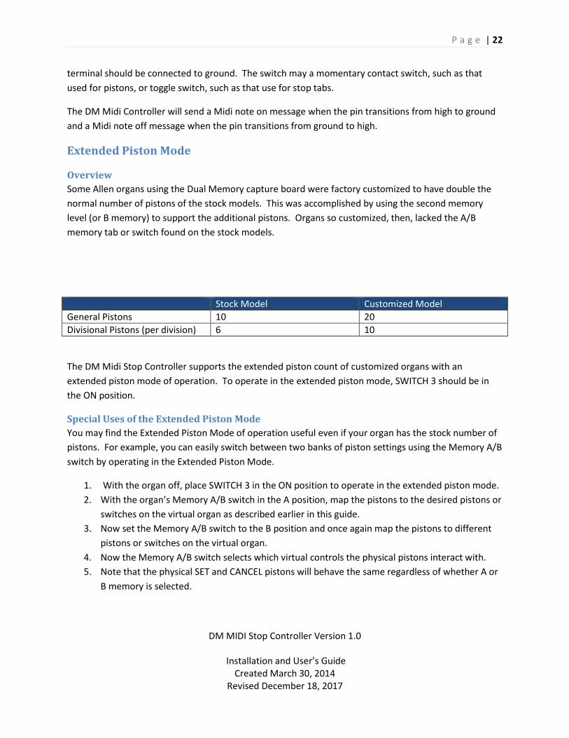
Some Allen organs using the Dual Memory capture board were factory customized to have double the
normal number of pistons of the stock models. This was accomplished by using the second memory
level (or B memory) to support the additional pistons. Organs so customized, then, lacked the A/B
memory tab or switch found on the stock models.
Stock Model Customized Model
General Pistons 10 20
Divisional Pistons (per division) 6 10
The DM Midi Stop Controller supports the extended piston count of customized organs with an
extended piston mode of operation. To operate in the extended piston mode, SWITCH 3 should be in
the ON position.
Special Uses of the Extended Piston Mode
You may find the Extended Piston Mode of operation useful even if your organ has the stock number of
pistons. For example, you can easily switch between two banks of piston settings using the Memory A/B
switch by operating in the Extended Piston Mode.
1. With the organ off, place SWITCH 3 in the ON position to operate in the extended piston mode.
2. With the organ’s Memory A/B switch in the A position, map the pistons to the desired pistons or
switches on the virtual organ as described earlier in this guide.
3. Now set the Memory A/B switch to the B position and once again map the pistons to different
pistons or switches on the virtual organ.
4. Now the Memory A/B switch selects which virtual controls the physical pistons interact with.
5. Note that the physical SET and CANCEL pistons will behave the same regardless of whether A or
B memory is selected.

P a g e | 23
DM MIDI Stop Controller Version 1.0
Installation and User’s Guide Created March 30, 2014
Revised December 18, 2017
Standalone Operation Mode (Optional Firmware Upgrade)
Overview
In some installations, it may be desirable to preserve the organ’s original tone generation and
combination action capture functionality to allow the instrument to be played without additional MIDI
software and connections. An optional firmware upgrade, available at the time of purchase or as a
retrofit, adds the following capabilities to the standard DM MIDI Stop Controller capabilities:
Self-contained emulation of the original Allen DM combination board
No MIDI connections required
Split operation using onboard combination memory with external MIDI receiving devices
Selectable A or B memory from console’s existing memory switch
Dedicated Set and Cancel pistons
Supports original Allen DM board piston compliment of 6 x 4 divisional pistons and 10 general
pistons
Automatic switch over between standalone and MIDI based operation
Nonvolatile memory storage requiring no backup battery.
Installation
The installation of the DM MIDI Stop Controller with the standalone option is identical to the standard
board. Follow the procedures outlined previously in this guide.
Standalone Mode Operation
When in the standalone mode combination settings are stored and recalled from the board’s internal
non-volatile memory. The console’s original piston functionality is preserved, that is, pistons are
assigned specific roles as divisional or general pistons. As with the organ’s original memory system,
there are two banks of memory – A & B. The console’s physical pistons select the active combination
and the active bank is chosen by the organ’s A/B memory tab or key switch as previously.
Split Mode Operation
When operating in the Standalone Mode, the DM MIDI board continues to send out MIDI messages for
piston presses and stop changes. This permits external MIDI devices to respond to console changes
while retaining and utilizing the onboard combination memory. This mode of operation is useful when
it is desired to send stop and piston changes to MIDI devices that will be used in conjunction with
organ’s built in tone generation.
Entering Standalone Mode Operation
DM MIDI boards with the Standalone Mode Option automatically default to the standalone mode when
the organ is turned on and will remain in that operational mode in the absence of any MIDI input. If
MIDI input is detected, the board will automatically switch to the standard full MIDI Mode Operation. If
P a g e | 24
DM MIDI Stop Controller Version 1.0
Installation and User’s Guide Created March 30, 2014
Revised December 18, 2017
this occurs, the organ must be turned off for approximately 15 seconds or more and then turned back
on to re-enter the standalone mode.
Automatic Switchover to MIDI Mode
DM MIDI boards with the Standalone Mode Option automatically default to the Standalone mode when
the organ is turned on; however, they automatically switch to the standard MIDI mode of operation
when a MIDI In message is received. Once the switchover occurs, the board will remain in the standard
MIDI mode until the organ is powered down regardless of whether additional MIDI messages are
received or not.
Hauptwerk sends out MIDI messages when it loads sample sets and when user interaction occurs. If a
MIDI connection exists between the MIDI Out of the computer and the MIDI In of the DM MIDI board,
the DM MIDI board will automatically switch from the standalone to the MIDI mode when it receives the
a message from Hauptwerk.
If a program or MIDI device other than Hauptwerk is being used, a MIDI message must be sent from it,
or from some other source, in order to switch the DM MIDI board to Standard MIDI Mode Operation.

P a g e | 25
DM MIDI Stop Controller Version 1.0
Installation and User’s Guide Created March 30, 2014
Revised December 18, 2017
Operational Summary
Mode MIDI Out Messages MIDI In Messages Notes
Standalone/Split Yes Not permitted MIDI note on/off, NRPN and controller messages sent to the board’s MIDI In port will cause a switch to MIDI Mode operation. There is no operational difference between the Standalone and Split mode other than whether the MIDI Out messages are being consumed by another device. Pistons are mapped to their respective divisions. SET and CANCEL pistons retain their original function but do not generate any MIDI messages. Combination Memory Level is selected by organ’s A/B memory key switch or memory tab.
Standard MIDI Yes Required MIDI note on/off, NRPN or Controller message must be sent to the board’s MIDI In port to enter this mode. Piston functionality and combination settings are determined by the external MIDI device or program. On board combination settings are retained but not settable or recallable in this mode.
Setting Combinations in Standalone Mode
The procedure for setting pistons when operating in the Standalone Mode is the same as the standard
Allen procedure.
1. Make sure you’re operating in the Standalone mode.
2. Select the memory bank, A or B, to which you wish to assign the combination using the key
switch or tab on the console.
3. Set the registration you wish to capture.

P a g e | 26
DM MIDI Stop Controller Version 1.0
Installation and User’s Guide Created March 30, 2014
Revised December 18, 2017
4. Press and hold the SET piston then press and release the piston to which you wish to assign the
registration. Then release the SET piston. Remember, that divisional pistons will only capture
those stops in their division, excluding couplers, while general pistons will capture settings
across all divisions including couplers.
Recalling Combinations in Standalone Mode
The procedure for recalling pistons when operating in the Standalone Mode is the same as the standard
Allen procedure.
1. Make sure you’re operating in the Standalone mode.
2. Select the memory bank, A or B, from which you wish to recall the combination using the key
switch or tab on the console.
5. Press the piston that was assigned the registration you wish to recall. Remember, that divisional
pistons will only recall stops in their division, excluding couplers, while general pistons will recall
settings across all divisions including couplers.
Cancel Piston
The General Cancel piston functions identically to the standard Allen General Cancel function and turns
all stops off.
Standalone Memory Retention
Combinations set in the Standalone are stored in non-volatile onboard memory and will be retained
indefinitely or until overwritten. No battery is required.
Limitations
The memory in which the Standalone mode combinations are stored has a specified limit of 100,000
write (storage) cycles. The firmware is optimized to only write to memory locations that have changed
from their previous settings. While this limit is not likely to be encountered under typical use, one
should be mindful that there is a limit to the number times a given piston combination can be changed.
There is no limit on the number of times a combination can be recalled.

P a g e | 27
DM MIDI Stop Controller Version 1.0
Installation and User’s Guide Created March 30, 2014
Revised December 18, 2017
Appendix
DIP Switch Configuration Switch Off On
1 Normal operation. LED will be on. Turning this switch to the Off position while the organ is turned on will exit the calibration mode.
Analog calibration mode. LED will be off while in the calibration mode. To enter the calibration mode, this switch has to be in the On position before the organ is turned on.
2 LDR input linearization mode for analog inputs 1 and 2.
Linear potentiometer mode for analog inputs 1 and 2.
3 Normal piston operating mode Extended piston operating mode.
4*
Midi Channel Stops: 6 Midi Channel Pistons: 10
Midi Channel Stops: 7 Midi Channel Pistons: 11
5 Not currently used Not currently used
6 Not currently used Not currently used
7 Not currently used Not currently used
8 Not currently used Not currently used
Except as noted, the switch positions are read, and corresponding operation modes selected, at power
up time. Changing a switch position while the organ is on will have no effect until the organ is turned off
and then back on.
* Switch 4 not used in boards manufactured prior 2016. Midi Stops Channel is always 5 for these
boards.
Midi Configuration
Channel Assignments
Board Manufacture Date
Switch 4 Stops Channel Pistons & Expression Channel
Prior 2016 N/A 5 10
2016 and later Off 6 10
On 7 11
Stop Control Messages
Sends and receives Midi Note On-Off messages on selected Stops Channel (see above table)
A note-on message is sent when a physical stop is turned on.
A note-off message is sent when a physical stop is turned off.
The receipt of a note-off message causes the physical stop to turn off. *

P a g e | 28
DM MIDI Stop Controller Version 1.0
Installation and User’s Guide Created March 30, 2014
Revised December 18, 2017
The receipt of a note-on message causes the physical stop to turn on. *
*General division stops require the sender to send the following NRPN message in addition to the note-
on/off message: NRPN, Stops Channel, NRPN number 10.
Piston and Expansion Messages
Sends Midi Note On-Off messages on Pistons & Expression Channel (see table above)
A note-on message is sent on switch closure (grounded)
A note-off message is sent on switch release (not grounded)
Expression and Analog Controllers
Analog Input 1: Controller 11 on Pistons & Expression Channel (see table above)
Analog Input 2: Controller 12 on Pistons & Expression Channel
Analog Input 3: Controller 13 on Pistons & Expression Channel
Analog Input 4: Controller 14 on Pistons & Expression Channel
Troubleshooting
Overview
Most problems can most quickly be identified by using a program such as Midi-Ox to view midi
messages to and from the controller board. Hauptwerk’s built in logging function may also be used for
this purpose. See the Hauptwerk User’s Guide.
Midi Messages Not Being Received by Hauptwerk
1. Midi cable not connected.
2. Midi cable is not connected correctly.
3. Organ is turned off
4. Connectors not seated properly.
5. Hauptwerk not listening on correct Midi channel
6. Calibration switch Switch 1 is ON.
Individual Stop/Piston Messages Not Being Received by Hauptwerk
1. Midi messages not being sent.
2. Stop not mapped to a virtual stop
3. Defective physical stop switch
4. Broken wire on connector
5. Defective controller board
Controller Messages Not Being Received by Hauptwerk
1. Midi messages not being sent.

P a g e | 29
DM MIDI Stop Controller Version 1.0
Installation and User’s Guide Created March 30, 2014
Revised December 18, 2017
2. Controller was not calibrated after being connected to analog input
3. Controller not mapped to virtual control.
4. Defective controller board
Physical Stop Doesn’t Change When Virtual Stop Changes
1. Midi messages not being sent or received
2. Midi input cable not connected.
3. Connectors not seated properly
4. Hauptwerk sending messages on wrong Midi channel
5. Stop is in General Division and NRPN message not being sent by Hauptwerk.
6. Stop is mechanically or electrically defective
7. Defective controller board.
Physical Stop Fails to Cancel with General Cancel
1. Defective stop
2. Physical stop not mapped to virtual stop.
Physical Stop Chatters When Virtual Stop Changes
There are two possible causes
1. An intermittent or dirty stop contact.
2. A Midi loop.
A dirty or intermittent stop contact can cause a rapid stream of messages to be sent between the
console and Hauptwerk as the physical and virtual stop attempt to assume each other’s state setting up
a race condition similar to a Midi loop.
To troubleshoot, in Hauptwerk, turn off Midi output for the stop or disconnect the Midi cable plugged in
to the DM Midi Controller’s Midi In connector. Then use Midi-Ox or an equivalent program to monitor
the midi messages being sent from the DM Midi Controller Board. A single message should be sent for
each change of the stop from up to down and vice-versa. If a continuous or long stream of messages is
being sent on these transitions, the physical stop contact needs to cleaned and adjusted.
A Midi loop is the condition where an endless stream of messages is exchanged between two or more
Midi devices on the same channel. Here’s an example:
1. Device A sends a message to Device B.
2. Device B receives the message and as a result returns a response message to Device A.
3. Device A receives the message and as a result sends another message to Device B which repeats
the process.

P a g e | 30
DM MIDI Stop Controller Version 1.0
Installation and User’s Guide Created March 30, 2014
Revised December 18, 2017
Neither of these conditions should occur in a properly configured system as the DM Midi Controller is
programmed to not permit them to occur when used with Hauptwerk. If chatter does occur, it is likely
that a third Midi device is present on the port in addition to the DM Midi Controller and Hauptwerk and
it is this third device implementing a loop.
NOTE: Stop chatter can result in damage to the stop mechanism and the capture power supply if
allowed to persist for a prolonged period. Immediately exit Hauptwerk or turn off the organ if stop
chatter is observed.

P a g e | 31
DM MIDI Stop Controller Version 1.0
Installation and User’s Guide Created March 30, 2014
Revised December 18, 2017
Addendum – Multi DM Systems Most organs built using the DM Capture system used a single board; however, some large four manual
custom instruments required two boards and were so equipped.
If two MIDI Stop Controller boards are to be used in your installation, make sure that SWITCH 4 on the
DIP switches are set differently for each board.

P a g e | 32
DM MIDI Stop Controller Version 1.0
Installation and User’s Guide Created March 30, 2014
Revised December 18, 2017
Addendum – Firmware Upgrade Upgrading the DM MIDI Stop Controller with new firmware consists of replacing the firmware integrated
circuit with the new version and repeating the analog calibration steps for any connected expression
pedals or other analog controllers.
NOTE: Changes to the default MIDI channels were made in later versions of the firmware; however,
unless otherwise noted at the time of your order, your upgrade preserves the channel mappings of
your original firmware to avoid the necessity of reprogramming your VPO settings. Make sure that
board’s DIP switch 4 is in the “Off” position unless you are using multiple DM boards in your
installation.
1. Disconnect power from the organ.
2. It is unnecessary to uninstall the DM MIDI Stop Controller board to perform the upgrade.
3. Locate the firmware chip on the circuit board. It is the only socketed integrated circuit.
4. Note the orientation of the notch on one end of the chip.
5. Remove the original firmware chip. The best way of doing this is by using an IC chip puller. If a
chip puller is not available, use a small screwdriver to gently pry up each end of the chip slightly
then pull the chip out of the socket by grasping both ends of the chip with your fingers and
pulling straight up.
Danger!
Potentially lethal voltages are present inside the organ console. Disconnect all power from
the organ before beginning the installation process.
Caution
Organ circuitry is sensitive to, and maybe damaged by, static electricity discharge. Always
discharge yourself by first touching a metal chassis or another ground point within the organ
before handling organ circuit boards and connectors.

P a g e | 33
DM MIDI Stop Controller Version 1.0
Installation and User’s Guide Created March 30, 2014
Revised December 18, 2017
6. Carefully insert the new chip into the socket making sure to orient the notch in the same
direction as the original. It may be necessary to bend the pins of the IC slightly inward to align
the pins with the socket.
7. Make sure that all the pins are inserted and that none of them have been bent out of position.
8. If you are using the DM MIDI Stop Controller for your expression pedals or other analog inputs,
repeat the Analog Calibration procedure found here for each.
9. Unless you are using multiple DM MIDI boards in your installation, make sure that DIP switch 4
is in the “Off” position.
10. This completes the firmware upgrade process.