m 152160 msi-7300 - la crosse scale, · pdf fileintroduction 1 1.0 introduction the msi-7300...
TRANSCRIPT

MSI-7300Dyna-Link 2 Tension Dynamometer
Operator’s Manual
152160 Rev B

Technical training seminars are available through Rice Lake Weighing Systems.
Course descriptions and dates can be viewed at www.ricelake.com/trainingor obtained by calling 715-234-9171 and asking for the training department.
Contents
1.0 Introduction ................................................................................11.1 Safety ..........................................................................................21.2 Key Descriptions ........................................................................31.3 General Information ...................................................................41.4 MSI-7300 Annunciators .............................................................61.5 Specifications .............................................................................7
1.5.1 Standard Capacities and Resolution ..........................................81.6 Features ......................................................................................91.7 Options .....................................................................................101.8 Unpacking ................................................................................101.9 Assembly ..................................................................................101.10 Battery Replacement ...............................................................11
2.0 Operation ..................................................................................122.1 Power .......................................................................................122.2 Zero ..........................................................................................12
3.0 User Key Functions (F1and F2) ................................................133.1 OFF ...........................................................................................133.2 TEST .........................................................................................133.3 TOTAL .......................................................................................13
3.3.1 MANUAL TOTAL .....................................................................133.3.2 AUTO TOTAL ..........................................................................14
3.4 Clear Total ................................................................................143.5 Net / Gross ...............................................................................143.6 TARE .........................................................................................14
3.6.1 To Tare and Display the Net Tension .......................................153.6.2 To Clear the Tare and Revert to Gross Tension .......................153.6.3 Tare- Rules for Use: ................................................................15
3.7 PEAK HOLD ..............................................................................153.8 2-UNITS/ 5-UNITS ....................................................................163.9 HI-RES ......................................................................................173.10 PRINT .......................................................................................17
4.0 Dyna-Link Setup .......................................................................184.1 Menu Map ................................................................................184.2 Function Keys ..........................................................................194.3 Auto-Off ....................................................................................204.4 Setpoints ..................................................................................214.5 Total Mode ...............................................................................234.6 Units ..........................................................................................244.7 Filter Setup ...............................................................................25
5.0 Calibration ................................................................................265.1 Calibration Menu ......................................................................26
© Rice Lake Weighing Systems. All rights reserved. Printed in the United States of America. Specifications subject to change without notice.
Rice Lake Weighing Systems is an ISO 9001 registered company. November 7, 2013

Rice Lake continually offers web-based video training on a growing selection
of product-related topics at no cost. Visit www.ricelake.com/webinars.
5.2 Initial Calibration ......................................................................295.3 Guidelines for Capacity and Resolution .................................315.4 C-Cal Calibration ......................................................................325.5 Auto Zero Maintenance (AZM) ................................................345.6 Service Counters ......................................................................35
6.0 Communication Setup .............................................................366.1 RF Option .................................................................................366.2 Printer Setup ............................................................................37
6.2.1 Standard Print Strings .............................................................386.2.2 Printer Output Setup ...............................................................39
6.3 Comm Port Hardware ..............................................................416.4 802.15.4 RF Network Setup .....................................................426.5 FCC Statement (For 802.15.4 Option) .....................................456.6 International RF CERTS (For 802.15.4 Option) .......................45
7.0 Appendix ..................................................................................467.1 Troubleshooting .......................................................................467.2 Error Codes ..............................................................................487.3 Mechanical Dimensions ...........................................................497.4 Firmware Update Procedure ...................................................50
The MSI Limited Warranty ............................................................52
ii MSI-7300 Operator’s Manual

1.0 IntroductionThe MSI-7300 Dyna-Link 2 is a combination of the sound and proven mechanical design of the industry standard Dyna-Link with today’s most advanced electronics to provide a superb feature set unmatched by any dynamometer in its class or price range.
The Dyna-Link 2 is versatile, reliable, accurate, and easy to operate. The multi-purpose tension dynamometer is ideal for situations in which headroom is at a minimum. It is designed with safety factors exceeding the industry standard and is fully sealed for outdoor use in any weather.
A remote display option is available to further enhance the safety and usability. The optional RF remote display allows tension monitoring from a distance and adds the ability to print and store data.
If you have any questions or comments, please contact MSI Scales
Phone (toll free): 1-800-874-4320
MSI SCALES
Authorized distributors and their employees can view or download this manual from the MSI Scales distributor site at: www.msiscales.com.
Introduction 1
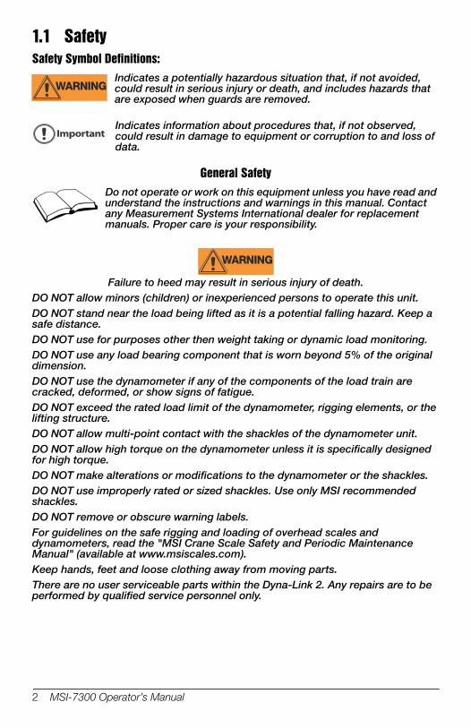
1.1 SafetySafety Symbol Definitions:
Important
WARNINGIndicates a potentially hazardous situation that, if not avoided, could result in serious injury or death, and includes hazards that are exposed when guards are removed.
Indicates information about procedures that, if not observed, could result in damage to equipment or corruption to and loss of data.
General Safety
WARNING
Do not operate or work on this equipment unless you have read and understand the instructions and warnings in this manual. Contact any Measurement Systems International dealer for replacement manuals. Proper care is your responsibility.
Failure to heed may result in serious injury of death.DO NOT allow minors (children) or inexperienced persons to operate this unit.DO NOT stand near the load being lifted as it is a potential falling hazard. Keep a safe distance.DO NOT use for purposes other then weight taking or dynamic load monitoring.DO NOT use any load bearing component that is worn beyond 5% of the original dimension.DO NOT use the dynamometer if any of the components of the load train are cracked, deformed, or show signs of fatigue.DO NOT exceed the rated load limit of the dynamometer, rigging elements, or the lifting structure.DO NOT allow multi-point contact with the shackles of the dynamometer unit.DO NOT allow high torque on the dynamometer unless it is specifically designed for high torque.DO NOT make alterations or modifications to the dynamometer or the shackles.DO NOT use improperly rated or sized shackles. Use only MSI recommended shackles.DO NOT remove or obscure warning labels.For guidelines on the safe rigging and loading of overhead scales and dynamometers, read the "MSI Crane Scale Safety and Periodic Maintenance Manual" (available at www.msiscales.com).Keep hands, feet and loose clothing away from moving parts.There are no user serviceable parts within the Dyna-Link 2. Any repairs are to be performed by qualified service personnel only.
2 MSI-7300 Operator’s Manual

Function key LEDsBattery low
Stable
Center of zero
5 Digit 1.22 in (31mm)Sunlight visible LCD Tension Display
Units with maximum capacity of 100000 lb and up come with a 6 digit 1 in (26 mm) display.
Note
Setpointalarm LEDs
Units & tensionmode annunciators
User programmable function keys
Figure 1-1. MSI-7300 Front Panel
1.2 Key Descriptions
POWER
Power Key - Turns the Dyna-Link 2 on and off. Used as cancel or last menu in the menu mode.
ZERO
Zero Key - Used to zero out residual tension on the link. Used as enter or save in the menu mode
Common uses are units change or peak hold for dynamic testing. F1- Programmable to user selectable functions, see Section 3.0. Default – peak hold. Functions as the ENTER/SELECT key in the menu mode.F2 - Programmable to user selectable functions, see Section 3.0. Default – display & function test. Functions as the scroll key in the menu mode.
Introduction 3

1.3 General Information1. If the text is discussing a function key, the function key will be displayed as Fx-
YYYYY with the programmed user key function in italics. F1 and F2 can both be programmed to all available user functions.
2. If a function key does not work, it is probably because the Dyna-Link 2 is not setup to support the key. For example, if the Function key is set for TOTAL, you must also setup the TOTAL mode in the setup menu.
3. When in setup menus, the ZERO key drops back one menu level. At the root menu level, the ZERO key stores the changes and returns to the tension mode.
4. When in setup menus, the POWER key returns you directly to the tension display without storing the changes.
4 MSI-7300 Operator’s Manual

5000 lbs / 2500 KGMAXIMUM CAPACITY
7300lb
Top shackle interface
Cotter pinsBattery access cover
Bottom shackle interface RS-232 port
Figure 1-2. Dyna-Link 2
Introduction 5
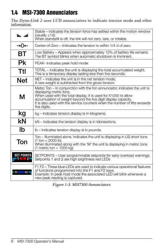
1.4 MSI-7300 Annunciators The Dyna-Link 2 uses LCD annunciators to indicate tension mode and other information.
Figure 1-3. MSI7300 Annunciators
Stable – indicates the tension force has settled within the motion window (usually ±1d). When standstill is off, the link will not zero, tare, or totalize.
Center-of-Zero – Indicates the tension is within 1/4 d of zero.
BT Low Battery – Appears when approximately 10% of battery life remains. The BT symbol blinks when automatic shutdown is imminent.
Pk PEAK- Indicates peak hold mode.
Ttl TOTAL – Indicates the unit is displaying the total accumulated weight. This is a temporary display lasting less than five seconds.
Net NET – Indicates the unit is in the net tension mode. A tare weight is subtracted from the gross tension.
M
Metric Ton – In conjunction with the ton annunciator, indicates the unit is displaying metric tons. When used with the total display, it is used for X1000 to allow accumulation of weight beyond the five digit display capacity. It is also used with the service counters when the number of lifts exceeds five digits.
kg kg – Indicates tension display is in kilograms.
kN kN – Indicates the tension display is in kilonewtons.
lb lb – Indicates tension display is in pounds.
TonTon – Illuminated alone, indicates the unit is displaying in US short tons (1 ton = 2000 lb). When illuminated along with the ‘M’ the unit is displaying in metric tons (1 metric ton = 1000 kg)
SETPOINTS – User programmable setpoints for early overload warnings. Setpoints 1 and 2 are high brightness red LEDs
F1 F2 – These blue LEDs are used to indicate various operational features of functions programmed into the F1 and F2 keys. Example: In peak hold mode the associated LED will blink whenever a new peak reading is captured.
0
6 MSI-7300 Operator’s Manual
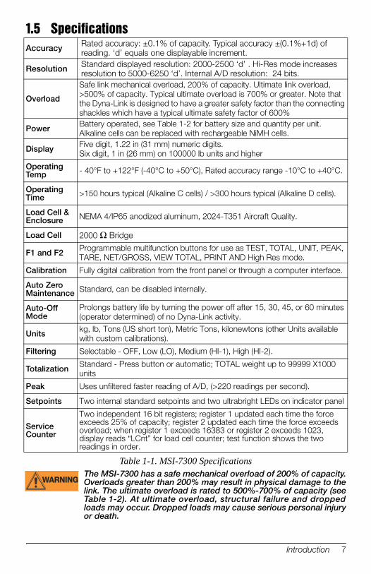
1.5 Specifications
Table 1-1. MSI-7300 Specifications
Accuracy Rated accuracy: ±0.1% of capacity. Typical accuracy ±(0.1%+1d) of reading. ‘d’ equals one displayable increment.
Resolution Standard displayed resolution: 2000-2500 ‘d’ . Hi-Res mode increases resolution to 5000-6250 ‘d’. Internal A/D resolution: 24 bits.
Overload
Power
Display
Operating Temp
Operating Time
Load Cell & Enclosure
Load Cell
F1 and F2
Calibration
Auto Zero Maintenance
Auto-Off Mode
Units
Filtering
Totalization
Peak
Setpoints
Service Counter
WARNINGThe MSI-7300 has a safe mechanical overload of 200% of capacity. Overloads greater than 200% may result in physical damage to the link. The ultimate overload is rated to 500%-700% of capacity (see Table 1-2). At ultimate overload, structural failure and dropped loads may occur. Dropped loads may cause serious personal injury or death.
Safe link mechanical overload, 200% of capacity. Ultimate link overload, >500% of capacity. Typical ultimate overload is 700% or greater. Note that the Dyna-Link is designed to have a greater safety factor than the connecting shackles which have a typical ultimate safety factor of 600%Battery operated, see Table 1-2 for battery size and quantity per unit. Alkaline cells can be replaced with rechargeable NiMH cells. Five digit, 1.22 in (31 mm) numeric digits.Six digit, 1 in (26 mm) on 100000 lb units and higher
- 40°F to +122°F (-40°C to +50°C), Rated accuracy range -10°C to +40°C.
>150 hours typical (Alkaline C cells) / >300 hours typical (Alkaline D cells).
NEMA 4/IP65 anodized aluminum, 2024-T351 Aircraft Quality.
2000 Ω Bridge
Programmable multifunction buttons for use as TEST, TOTAL, UNIT, PEAK, TARE, NET/GROSS, VIEW TOTAL, PRINT AND High Res mode.
Fully digital calibration from the front panel or through a computer interface.
Standard, can be disabled internally.
Prolongs battery life by turning the power off after 15, 30, 45, or 60 minutes (operator determined) of no Dyna-Link activity.
kg, lb, Tons (US short ton), Metric Tons, kilonewtons (other Units available with custom calibrations).
Selectable - OFF, Low (LO), Medium (HI-1), High (HI-2).
Standard - Press button or automatic; TOTAL weight up to 99999 X1000 units
Uses unfiltered faster reading of A/D, (>220 readings per second).
Two internal standard setpoints and two ultrabright LEDs on indicator panel
Two independent 16 bit registers; register 1 updated each time the force exceeds 25% of capacity; register 2 updated each time the force exceeds overload; when register 1 exceeds 16383 or register 2 exceeds 1023, display reads “LCnt” for load cell counter; test function shows the two readings in order.
Introduction 7
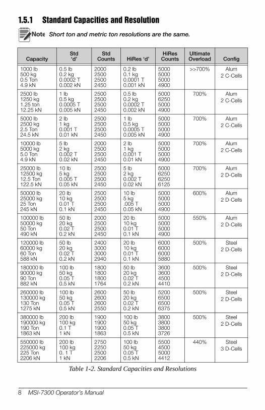
1.5.1 Standard Capacities and Resolution
Table 1-2. Standard Capacities and Resolutions
CapacityStd‘d’
StdCounts HiRes ‘d’
HiRes Counts
Ultimate Overload Config
1000 lb500 kg0.5 Ton4.9 kN
0.5 lb0.2 kg0.0002 T0.002 kN
2000250025002450
0.2 lb0.1 kg0.0001 T0.001 kN
5000500050004900
>>700% Alum2 C-Cells
2500 lb1250 kg1.25 ton12.25 kN
1 lb0.5 kg0.0005 T0.005 kN
2500250025002450
0.5 lb0.2 kg0.0002 T0.002 kN
5000625050004900
700% Alum2 C-Cells
5000 lb2500 kg2.5 Ton24.5 kN
2 lb1 kg0.001 T0.01 kN
2500250025002450
1 lb0.5 kg0.0005 T0.005 kN
5000500050004900
700% Alum2 C-Cells
10000 lb5000 kg5.0 Ton4.9 kN
5 lb2 kg0.002 T0.02 kN
2000250025002450
2 lb1 kg0.001 T0.01 kN
5000500050004900
700% Alum2 C-Cells
25000 lb12500 kg12.5 Ton122.5 kN
10 lb5 kg0.005 T0.05 kN
2500250025002450
5 lb2 kg0.002 T0.02 kN
5000625062506125
700% Alum2 D-Cells
50000 lb25000 kg25 Ton245 kN
20 lb10 kg0.01 T0.1 kN
2500250025002450
10 lb5 kg.005 T0.05 kN
5000500050004900
600% Alum2 D-Cells
100000 lb50000 kg50 Ton490 kN
50 lb20 kg0.02 T0.2 kN
2000250025002450
20 lb10 kg0.01 T0.1 kN
5000500050004900
550% Alum2 D-Cells
120000 lb60000 kg60 Ton588 kN
50 lb20 kg0.02 T0.2 kN
2400300030002940
20 lb10 kg0.01 T0.1 kN
6000600060005880
500% Steel2 D-Cells
180000 lb90000 kg90 Ton882 kN
100 lb50 kg0.05 T0.5 kN
1800180018001764
50 lb20 kg0.02 T0.2 kN
3600360045004410
500% Steel2 D-Cells
260000 lb130000 kg130 Ton1275 kN
100 lb50 kg0.05 T0.5 kN
2600260026002550
50 lb20 kg0.02 T0.2 kN
5200650065006375
500% Steel2 D-Cells
380000 lb190000 kg190 Ton1863 kN
200 lb100 kg0.1 T1 kN
1900190019001863
100 lb50 kg0.05 T0.5 kN
3800380038003726
500% Steel2 D-Cells
550000 lb225000 kg225 Ton2206 kN
200 lb100 kg0. 1 T1 kN
2750225025002206
100 lb50 kg0.05 T0.5 kN
5500450050004412
440% Steel3 D-Cells
Note Short ton and metric ton resolutions are the same.
8 MSI-7300 Operator’s Manual
1.6 Features• Designed to meet or exceed all U.S. and International safety and environmental
standards.• Greater than 150 hours operation with two standard Alkaline ‘C’ cells. Greater
than 300 hours with two standard Alkaline ‘D’ Cells (25000 lb/12500 kg capacities and above). Also works with off the shelf NiMH rechargeable cells.
• Automatic power off conserves battery life by sensing no activity after 15,30,45 or 60 minutes, determined by operator, and turns power off.
• Rugged construction throughout. IP65/NEMA4 for outdoor use.• Designed for use with USA made Crosby shackles (optional). • Shackle holes reinforced with steel sleeves (25000 lb/12500 kg capacities and
above) to reduce wear.• Shackle stops ensure ease of mounting. The stops prevent the shackles from
falling to the side of the unit and are held in position for easy rigging.• MSI’s ScaleCore technology provides precision, high resolution (2500 division
standard and up to 10,000 possible) 24 bit A/D conversion coupled with an advanced RISC microcontroller.
• Five large, 1.22 inch (31 mm) LCD digits for clear tension readings from a distance. Six digits, i in (26 mm) on units 100,000 lb and over.
• Easy to maintain: Full digital calibration assures reliable, repeatable measurements. Can be calibrated without test weights using MSI C-Cal technology.
• Selectable kg/lb/tons (US Short)/metric tons/kilonewtons.• Automatic or manual weight totalization for loading operations.• Easily customized for special applications. • Hi speed PEAK mode for stress and drop test analysis.• Two setpoints can be set for any in-range tension/weight value for operator alerts
or process control. Optional audible alarm output.• ScaleCore technology provides quick and easy firmware updates and calibration/
setup backup.• Two Service counters ensure load train safety by warning the user to perform
safety checks when the lift count gets high or the Dyna-Link has been overloaded repeatedly. Counter 1 (LFCnt) records the number of lifts above 25% of capacity. Counter 2 (OLCnt) records the number of times the Dyna-Link overloads.
Introduction 9

1.7 OptionsOptions which you may have ordered with your Dyna-Link 2 may include the following:
• Audible alarm (triggered by setpoint 1)• Top and bottom shackles• Portable carry case• Serial I/O cable (RS-232)• RF remote display (will also operate hard-wired). See RF remote display for
ScaleCore user guide.• Hardwired cable for remote display.• RF remote modem, RS-232, for direct connection to computers, scoreboards, or
serial printers. See RF modem for ScaleCore user guide.• RF remote modem, USB, for direct connection to computers. See RF modem for
ScaleCore user guide.• RF remote gateway for direct connection to an Ethernet LAN and for use with
MSI’s SCCMP program. See RF modem for ScaleCore user guide.• RF or hardwired scoreboard display.
1.8 Unpacking When unpacking the Dyna-Link 2 from the shipping container, ensure that all assembly parts are accounted for. Check for any visible damage and immediately report any damage to your shipper. Retain the original shipping container for future shipping or transporting.
1.9 Assembly1. Identify and locate the following:
• Batteries, two ‘C’ cells or ‘D’ cells depending on capacity• Top shackle and pin (option or customer supplied)• Bottom shackle and pin (option or customer supplied)• Two cotter pins
2. Slide top shackle over load cell and insert the pin. 3. Screw the shackle nut onto the pin.
WARNING
Note
NoteIt is not necessary or desirable to tighten the nut too tight. Make sure the nut is down far enough to expose the cotter pin hole.
4. Lock the shackle pin in place with the supplied cotter pin. Bend the cotter pin. 5. Repeat steps 1-3 for the bottom shackle.6. Remove the battery access port cover with a coin or a large screwdriver.7. Insert the two batteries, positive end first, into the battery shaft.8. Reinstall the battery access port cover. The Dyna-Link 2 is now ready for use.
The Dyna-Link2 will automatically start when the batteries are installed.
The Dyna-Link 2 load train will be unsafe for use if the shackle pins are not properly secured with cotter pins.
10 MSI-7300 Operator’s Manual

1.10 Battery ReplacementDisposable BatteriesThe BT annunciator will display when the is battery is beginning to get low. When the BT annunciator starts to blink, the batteries are close to being completely drained. For maximum life, use the batteries until the system shuts off.
Rechargeable BatteriesWhen using Nickle-Metal-Hydride (NiMH) Cells, it is recommended that the cells are recharged immediately after the BT annunciator starts to blink. Do not allow the batteries to discharge completely, it may compromise the recharge life of the battery.NiMH Cells in C and D sizes have a lower capacity then the Alkaline C and D sizes. MSI recommends having two sets of NiMH batteries, so one set can be charging while the other is in use.
NoteNiMH ‘D’ cells are often repackaged ‘C’ cells so you don’t get an increase in battery life for Dyna-Links large enough for ‘D’ cells. The use of NiCad batteries is not recommended.
If the Dyna-Link 2 will not be used for an extended period, the batteries should be removed. A small current is used when powered off which will discharge the batteries in about six months.
Introduction 11
12 MSI-7300 Operator’s Manual
2.0 Operation
2.1 PowerTo turn on the Power
1. Press POWER
.
• The LCD will show all segments for a display test.• The software version number will display.
The Dyna-Link 2 is ready for use.
2.2 ZeroTakes out small deviations in zero when the Dyna-Link 2 is unloaded. See Section 3.6 for zeroing (Taring) package or pallet weights.
Note
NoteThe tension reading must be stable within the motion window for the zero function to work.
1. Press ZERO
. The display reads 0 (or 0.0 or 0.00, etc).
The backup memory stores the zero reading, and can restore it even if power fails.
Zero - Rules for Use:• Works in GROSS mode or NET mode. Zeroing while in NET mode will zero
the gross tension causing the display to show the negative tare value. • The unit must be stable within the motion window, it will not zero until the
stable annunciator is on. • The unit will “remember” that it has a zero request for two seconds. If motion
clears in that time, it will zero. • The unit will accept a zero setting over the full range of the Dyna-Link. Zero
settings above 4% of full Dyna-Link will subtract from the overall capacity. For example, if you zero out 100 lb on a 1000 lb Dyna-Link, the overall capacity will reduce to 900 lb plus the allowed over-range amount.
3.0 User Key Functions (F1and F2)There are optional functions that can be programmed for the function keys (F1 andF2) on the front panel, as well as on the RF remote display. See Section 4.2 for setup instructions.
NoteThe functions PRINT (F3), and TARE are available full time on the RF remote display.
3.1 OFFNo USER key function assigned. The F-Key is disabled.
3.2 TESTThe TEST function provides an LCD test that lights all LCD segments and the LED at once and then counts from 00000 to 99999. Other internal tests are performed and if any test fails, an error code will display. See Section 7.2 for a description of all error codes.
3.3 TOTAL
NoteThe Total Mode must be programmed from the setup menus before the USER key will function. See Section 4.5.
For accumulation of multiple weighments. The accumulator always uses the displayed weight, so GROSS and NET readings can be added into the same TOTAL.
There are four modes of totalizing: manual and three auto modes.
The manual mode requires the TOTAL key be pressed with the tension on the unit. The tension will then be added to the previously accumulated value. This assures that a weight on the scale is only added to the total once. Both the manual and three auto total modes require that the tension on the Dyna-Link return below 0.5% (relative to full scale) of GROSS ZERO or NET ZERO before the next weighment can be added. Applied weight must be ≥1% of full scale above GROSS ZERO or NET ZERO before it can be totaled.
3.3.1 MANUAL TOTALThe Fx-TOTAL key under the MANUAL TOTAL mode functions in this manner:
1. With the tension at more than 1% of capacity, push the Fx-TOTAL key to add the current tension to the TOTAL weight. The Fx LED blinks to indicate the tension value was accepted. The TOTAL LCD annunciator and the total weight is displayed for about five seconds, then the number of samples is displayed for about two seconds.
2. Remove the weight, when the tension is less than 1% of capacity, place next load to be accumulated on the unit.
3. Repeat until all loads to be accumulated have been added to the total.4. To view the total weight accumulated, push the Fx-TOTAL key with the tension
at less than 1% of capacity (no weight on unit), the total weight will display for five seconds (view total) without changing the total value. The TOTAL LCD annunciator and the total weight is displayed for about five seconds and then the number of samples is displayed for about two seconds.
User Key Functions (F1and F2) 13

3.3.2 AUTO TOTALThe Fx-TOTAL key under the AUTO TOTAL mode functions as auto total on/auto total off:The auto mode has three variations which are programmed in the setup menu:
• AutoLoad – Any settled tension above the ‘rise above’ threshold will be automatically totaled. Then the Dyna-Link must fall below the ‘drop below’ threshold before another total is allowed.
• AutoNorm – This mode takes the last settled weight to auto total with. The total occurs only once the scale goes below the threshold. This allows the load to be adjusted without a total occurring. Once the load is removed, the scale uses the last settled reading for total.
• AutoHigh – Similar to the AutoNorm mode except the scale uses the highest settled reading. Useful for loads that can’t be removed all at once.
3.4 Clear TotalThe Fx-VIEW TOTAL key activates the total weight display followed by the number of samples. While the display is showing the total, total is cleared by pressing ZERO.
3.5 Net / GrossSwitches the display between net and gross modes. Net tension is defined as gross tension minus a tare weight. To switch between net mode and gross mode:
1. Press the Fx-NetGross key (setup to the net/gross function).2. The Fx-NetGross key will only function if a tare value has been established.3. Switching back to gross mode from net mode will not clear the tare value. This
allows the operator to use the gross mode temporarily without having to reestablish the tare value. Only clearing the tare or setting a new tare will change the tare value held before switching into gross mode.
3.6 TAREIn force measurement applications, tare is useful as a way to display differential force. By taring out a known force, only positive and negative deviations from the tared force are displayed. This can also increase accuracy as any initial error is removed leaving only slope error. In scale applications, tare is typically used to zero out a known weight such as rigging, a packing container, or pallet and display the load in NET tension/weight. To use tare, one of the two function keys must be configured to the TARE function. A tare value is entered by pressing the Fx-TARE key. The TAREfunction in the Dyna-Link 2 is defined as a tare-in/tare-out operation. The first press of the Fx-TARE key stores the current tension/weight as a tare value and then the Dyna-Link subtracts the tare value from the gross tension and changes the display to NET mode. The next press of the Fx-TARE key will clear the tare value and revert the display to GROSS mode. The optional RF remote display has a TARE key permanently available.
14 MSI-7300 Operator’s Manual
3.6.1 To Tare and Display the Net Tension1. Press (programmed as TARE).
2. The tension reading must be stable within the motion window for the tare function to work.
3. The digits display 0 and the tension mode changes to NET.4. The backup memory in the Dyna-Link 2 stores the tare reading, and can restore
it even if power fails.
3.6.2 To Clear the Tare and Revert to Gross Tension1. Press (programmed as TARE).
2. The NET annunciator will turn off.3. Absence of the NET annunciator is the only indication that you are in GROSS
tension mode.
NoteTo view the GROSS tension without clearing the tare value, program the remaining function key to the function NET/GROSS.
3.6.3 Tare- Rules for Use:1. Only positive gross tension readings can be tared.2. The stable annunciator must be on. The tension/force reading must be stable.3. Setting or changing the tare has no effect on the gross zero setting.4. Taring will reduce the apparent over range of the Dyna-Link. For example,
taring 100 pounds of rigging on a 1000 lb Dyna-Link, the Dyna-Link will overload at a net tension of 900 lb (1000-100) plus any additional allowed overload (usually ~4% or 9d).
5. The Dyna-Link stores the tare value in non-volatile memory is restored when power is cycled.
3.7 PEAK HOLDPeak hold will only update the display when a higher peak tension reading is established. The peak hold function uses a high speed mode of the A/D converter allowing it to capture transient tensions at a far higher rate than typical dynamometers.
Peak hold is cleared and re enabled with the Fx-Peak Hold key. When a new peak is detected, the Fx LED will flash three times. The accuracy of the system in peak hold mode is slightly reduced to .2% of capacity ± 5d. The filter setting is turned off while in peak hold mode to ensure the fastest acquisition rate.
Example Peak Hold Application
The peak hold function is useful in materials and ‘Fall’ tests. Common tests for fiber rope include overall breaking strain (OB€), breaking force, and cycled breaking strain. The Dyna-Link 2 combined with a force test stand, meets the speed and accuracy requirements to properly conduct these tests.
User Key Functions (F1and F2) 15
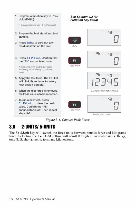
1) Program a function key to PeakHold (P-Hld)
In this example we’ll use F1 for Peak Hold.
2) Prepare the test stand and testsample.
3) Press ZERO to zero out anyresidual strain on the link.
4) Press F1 PkHold . Confirm thatthe “Pk” annunciator is on.
A small jump in the reading may occur
depending on the stability of your test
stand.
5) Apply the test force. The F1 LEDwill blink three times for everynew peak it detects.
6) When the test force is removed,the Peak value can be recorded.
7) To run a new test, press F1 PkHold to clear the peakvalue. Confirm the “Pk”annunciator is off. Then repeatsteps 3-6.
Peak Hold
kg lbM kNTonkg lbM kNTonPk
kg lbM kNTonkg lbM kNTonPk
Example Peak Captured Value
Peak Hold
kg lbM kNTonkg lbM kNTon
kg lbM kNTonkg lbM kNTon
Peak Cleared Value
F1
F1
0
ZERO
See Section 4.2 for Function Key setup
Figure 3-1. Capture Peak Force
3.8 2-UNITS/ 5-UNITSThe Fx-2.Unit key will switch the force units between pounds force and kilograms force. Selecting the Fx-5.Unit setting will scroll through all available units: lb, kg, tons (U.S. short), metric tons, and kilonewtons.
16 MSI-7300 Operator’s Manual

3.9 HI-RESSet a function key (Fx) to Hi-Res, see Section 4.0.Press the Fx key programmed to display the high resolution mode (see Table 1-2 on page 8). The display will stay in high resolution mode until the selected Fx key is pressed again, or power is cycled. While in the hi-res mode the appropriate Fx LED will blink continuously at a slow rate.Hi-res mode does not increase the accuracy, but allows for smaller weight increments to be displayed. Use Tare or the ZERO key to zero out any initial error. Hi-res mode will make the Dyna-Link 2 more sensitive to motion and movement resulting in a less stable display. When hi-res is on, the filter is automatically set to the Hi-1 setting (if Hi-2 is already set, then the filter is not changed). This will have a small effect on settling time. When hi-res is turned off, the filter setting resets to the previous filter setting.
3.10 PRINTSet a function key (Fx) to Print, see Section 4.0.Pressing the Fx key outputs a configured text string to the RS-232 port on the base of the unit. If an F-Key is programmed as print and the print setup is configured as continuous, then the Fx key is used for start print/stop print. See Section 6.2 for more details on data output. The print function is always available on the optional RF remote display, so it is not necessary to program an F-Key to “print” if you intend to trigger print outputs from the remote. However, if you program F1 or F2 to “print” then pushing F1 or F2 on the Dyna-Link will cause the comm port on the remote to output the selected data string.If the RF remote display option is installed, the Dyna-Link cannot use its built in comm port except for hard-wire connections to the RF remote display or firmware updates.
User Key Functions (F1and F2) 17
4.0 Dyna-Link Setup
4.1
Number Entry
Off
Test Display
Total
View Total
Net/Gross
Tare
Peak Hold
2 Units
5 Units
Hi Res
F1 & F2 KEYFUNCTIONS
TOTAL MODETotal Off (default)
Total On Manual
Autototal on Load
Autototal Last
Autototal on High Load
F2 Key F1
F2 Key F2
Auto Off Time
Set Point 1
Set Point 2
Total Mode
Weight Filter
Weight Units
SETUP MENU
Disabled (default)
15 minutes
30 minutes
45 minutes
60 minutes
AUTO OFF TIME
OFF (disabled)
Low (default)
High Filter
Very High Filter
SOFTWARE FILTER
With the power on, press the F2
key and power key simultaneously
Set Point Off(default)
Greater Than
Less Than Totals on first stable load
Totals the last stable load before zero return
Totals the highest stable load
Totals by pressing an assigned F-key
Autototal Last and Autototal High total when the scale is unloaded.
SP WEIGHT MODEGross (default)
Net or Gross
Total
Total Count (n)
(F1 default)
lbkgTon
MTonkN
Press Simultaneously
0
ZEROPOWER
F2F1
F2
PoundskilogramsShort TonsMetric TonskiloNewtons
Menu Map
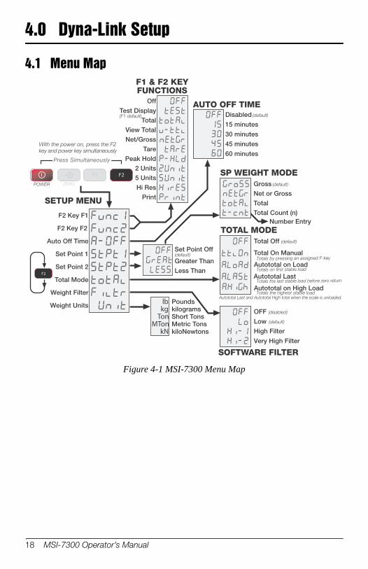
Figure 4-1 MSI-7300 Menu Map
18 MSI-7300 Operator’s Manual
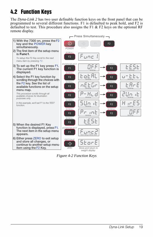
4.2 Function KeysThe Dyna-Link 2 has two user definable function keys on the front panel that can be programmed to several different functions. F1 is defaulted to peak hold, and F2 is defaulted to test. This procedure also assigns the F1 & F2 keys on the optional RF remote display.
SCROLL
F2
SCROLL
F2
SCROLL
F2
SCROLL
F2
SCROLL
F2
ENTER/SELECT
F1
ENTER/SELECT
F1
blinking
blinking
blinking
blinking
blinking
1) With the 7300 on, press the F2key and the POWER keysimultaneously.
2) The first item of the setup menuis Func1.To setup the F2 Key scroll to the next
menu item by pressing F2.
3) To set up the F1 key press F1.The current F1 key function isdisplayed.
4) Select the F1 key function byscrolling through the choices withthe F2 key. See the list ofavailable functions on the setupmenu map.This procedure scrolls through allavailable choices for illustrationpurposes only.
In this example, we’ll set F1 to the TESTfunction.
5) When the desired F1 Keyfunction is displayed, press F1.The next item in the setup menuappears.
6) Either press ZERO to exit setupand store all changes, orcontinue to another setup menuitem using the F2 Key.
Next Setup Menu Item
Store and return toweight display
SCROLL
F2
SCROLL
F2
SCROLL
F2
SCROLL
F2
SCROLL
F2
SCROLL
F2
blinking
blinkingblinking
blinking
blinking
0
EXIT/SAVE
ZERO
Press Simultaneously
POWER
F2
SCROLL
F2
blinking
SCROLL
F2
blinking
blinking blinking
0
ZERO
F1
Figure 4-2 Function Keys
Dyna-Link Setup 19
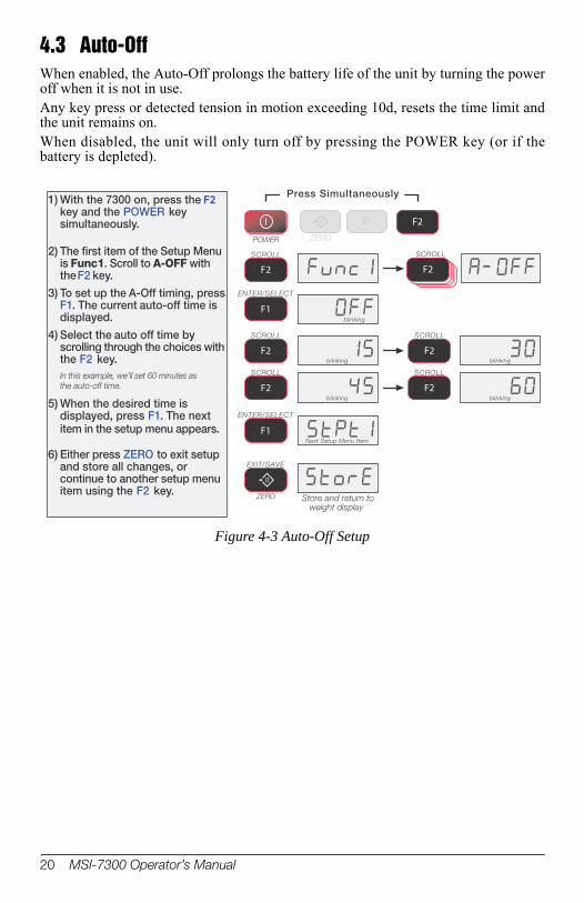
4.3 Auto-OffWhen enabled, the Auto-Off prolongs the battery life of the unit by turning the power off when it is not in use. Any key press or detected tension in motion exceeding 10d, resets the time limit and the unit remains on. When disabled, the unit will only turn off by pressing the POWER key (or if the battery is depleted).
1) With the 7300 on, press the F2key and the POWER keysimultaneously.
2) The first item of the Setup Menuis Func1. Scroll to A-OFF withtheF2 key.
3) To set up the A-Off timing, pressF1. The current auto-off time isdisplayed.
4) Select the auto off time byscrolling through the choices withthe F2 key.In this example, we’ll set 60 minutes as
the auto-off time.
5) When the desired time isdisplayed, press F1. The nextitem in the setup menu appears.
6) Either press ZERO to exit setupand store all changes, orcontinue to another setup menuitem using the F2 key.
Press Simultaneously
POWER
F2
SCROLL
F2
SCROLL
F2
SCROLL
F2
SCROLL
F2
SCROLL
F2
ENTER/SELECT
F1
0
EXIT/SAVE
ZERO
F2
SCROLL
ENTER/SELECT
F1blinking
blinking
blinking
Next Setup Menu Item
Store and return toweight display
blinking
blinking
0
ZERO
F1
Figure 4-3 Auto-Off Setup
20 MSI-7300 Operator’s Manual

4.4 SetpointsThe Dyna-Link 2 supports two setpoints. Common uses of set points are for warnings or process control. The MSI-7300 Dyna-Link 2 comes standard with two high brightness red LED outputs for a triggered set point. The MSI-7300 Dyna-Link 2 has an audible output option that is triggered by setpoint 1. Contact MSI for other setpoint output options.
1) With the 7300 on, press the F2and POWER keyssimultaneously.
2) Scroll through the setup menuchoices by pressing the F2 key.Stop when the LED displaysStPt1 or StPt2.
3) When the desired setpoint isdisplayed, press F1. The displayblinks OFF, or if previouslyprogrammed, the last set mode.
4) Select the setpoint mode byscrolling through the choices withthe F2 key. GrEAt (greater than)indicates the setpoint will triggerwhen the tension exceeds thevalue. LESS (less than) willtrigger the setpoint when thetension is less than the value.This example scrolled through all availablechoices for illustration purposes only.
5) When the desired setpointmode is displayed, press F1.
6) Next select the type of tensionor weight value the set point isassigned to. Use the F2 key toscroll through the choices.
This example scrolled through allavailable choices for illustrationpurposes only.In this example, we’llenter Gross as the tension modebecause we are going to use the setpoint as a safety warning.
7) When the desired weight modeis shown, push F1. Next thecurrent setpoint value isdisplayed. If there was a previous
value, it is displayed. If no value has
been entered, a zero will appear. To
keep the displayed value, press ZERO.
blinking
Current Value (if any)
Set Point responds to Grosstension, regardless of thedisplay mode.
Set Point responds to thetension on the display, Netor Gross Weight.
Set Point responds to theTotaled Weight.
Set Point responds tothe Total Count (numberof samples).
Press Simultaneously
POWER
F2
F2
SCROLL
ENTER/SELECT
F1
ENTER/SELECT
F1
SCROLL
F2
SCROLL
F2
SCROLL
F2
SCROLL
F2
SCROLL
F2
SCROLL
F2
F2
SCROLL
Set Point responds to Grosstension, regardless of thedisplay mode.
blinking
blinking
blinking
blinking
blinking
0
ZERO
F1
Figure 4-4 Setpoint Setup
Dyna-Link Setup 21
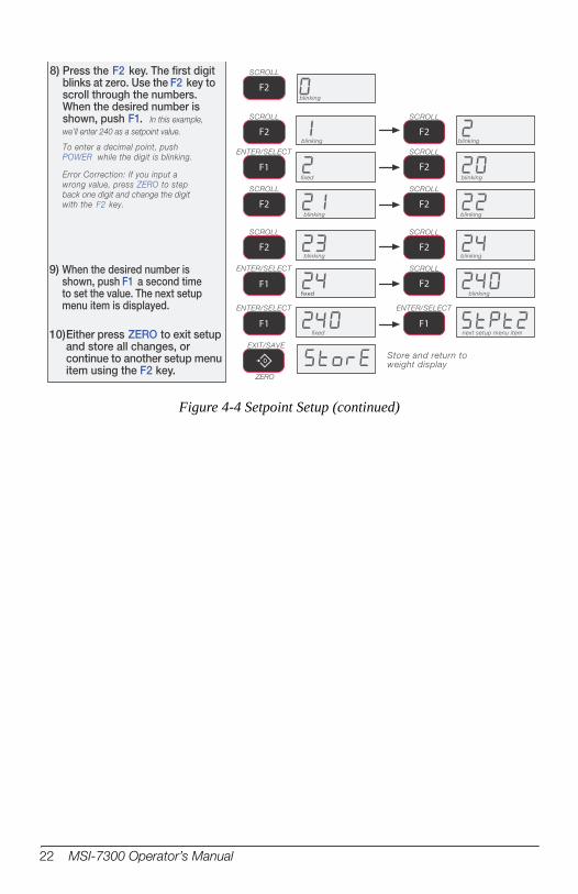
8) Press the F2 key. The first digitblinks at zero. Use the F2 key toscroll through the numbers.When the desired number isshown, push F1. In this example,
we’ll enter 240 as a setpoint value.
To enter a decimal point, push
POWER while the digit is blinking.
Error Correction: If you input a
wrong value, press ZERO to step
back one digit and change the digit
with the F2 key.
blinking
ENTER/SELECT
F1
SCROLL
F2
SCROLL
F2
SCROLL
F2
SCROLL
F2
SCROLL
F2
SCROLL
F2
fixed
blinking blinking
blinking
blinking blinking
9) When the desired number isshown, push F1 a second timeto set the value. The next setupmenu item is displayed.
10)Either press ZERO to exit setupand store all changes, orcontinue to another setup menuitem using the F2 key.
fixed blinking
blinking blinking
fixed next setup menu item
Store and return toweight display
SCROLL
F2
SCROLL
F2
SCROLL
F2
ENTER/SELECT
F1
ENTER/SELECT
F1
ENTER/SELECT
F1
0
EXIT/SAVE
ZERO
Figure 4-4 Setpoint Setup (continued)
22 MSI-7300 Operator’s Manual

4.5 Total ModeThe MSI-7300 Dyna-Link 2 can keep track of all weighments using the total feature. Either manual total, which totals by pushing a configured USER key on the front panel or the optional RF remote display, or auto-total which can be used to automatically add up each weighment. See the total mode descriptions for details on the various total modes. To use manual total, you must also program a user key. Auto total modes do not need a user key, but if a user key is setup for total, then it will function as a total on/total off.
1) With the 7300 on, press the F2key and the POWER keysimultaneously.
2) The first item of the setup menuis Func1. Scroll to totaL withthe F2 key.
3) To setup the total mode, pressF1. The current total modesetting is displayed.
4) Select the total mode by scrollingthrough the choices with the F2key.In this example, we’ll set the total modeto the auto-high mode. The auto highmode uses the highest stable readingas the total value, and totals when theload is removed.
5) When the desired total modesetting is displayed, press F1.The next item in the setup menuappears.
6) Either press ZERO to exit setupand store all changes, orcontinue to another setup menuitem using the F2 key.
Next Setup Menu Item
Total last stable load
Total with pushbutton
Store and return toweight display
Press Simultaneously
POWER
F2
SCROLL
F2
SCROLL
F2
SCROLL
F2
SCROLL
F2
ENTER/SELECT
F1
ENTER/SELECT
F1
0
EXIT/SAVE
ZERO
F2
SCROLL
Total on stable load
Total highest stable Load
0
ZERO
F1
Figure 4-5 Total Mode Setup
Dyna-Link Setup 23
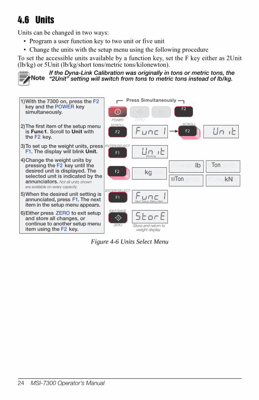
4.6 UnitsUnits can be changed in two ways:
• Program a user function key to two unit or five unit• Change the units with the setup menu using the following procedure
To set the accessible units available by a function key, set the F key either as 2Unit (lb/kg) or 5Unit (lb/kg/short tons/metric tons/kilonewton).
1)With the 7300 on, press the F2key and the POWER keysimultaneously.
2)The first item of the setup menuis Func1. Scroll to Unit withthe F2 key.
3)To set up the weight units, pressF1. The display will blink Unit.
4)Change the weight units bypressing the F2 key until thedesired unit is displayed. Theselected unit is indicated by theannunciators. Not all units shown
are available on every capacity.
5)When the desired unit setting isannunciated, press F1. The nextitem in the setup menu appears.
6)Either press ZERO to exit setupand store all changes, orcontinue to another setup menuitem using the F2 key.
Next Setup Menu Item
Blinking
Store and return toweight display
kg lbM kNTonkg lbM kNTon kg lbM kNTon
kg lbM kNTon kg lbM kNTon
Press Simultaneously
POWER
F2
ENTER/SELECT
F1
ENTER/SELECT
F1
SCROLL
F2 F2
SCROLL
0
EXIT/SAVE
ZERO
F2 kg lbM kNTonkg lbM kNTon kg lbM kNTon
kg lbM kNTon kg lbM kNTon
0
ZERO
F1
NoteIf the Dyna-Link Calibration was originally in tons or metric tons, the “2Unit” setting will switch from tons to metric tons instead of lb/kg.
Figure 4-6 Units Select Menu
24 MSI-7300 Operator’s Manual

4.7 Filter SetupChanging the filter settings allows the Dyna-Link to adjust to situations where there is a lot of movement in the lift or the crane structure. If the reading is not stable, it can often be improved by increasing the filter setting. Settling time will be longer as the filter setting is increased. However, the MSI-7300 Dyna-Link 2 employs algorithms that speed up large tension changes while still controlling vibration even with higher filter settings.
1) With the 7300 off, press and holdthe F2 key, then press thePOWER key....or while the 7300 is on, press F2 and
POWER simultaneously.
2) The first item of the setup menuis Func1. Scroll to Filtr withthe F2 key.
3) To set up the filter, press F1. Thedisplay will blink the current filtersetting.
4) Change the filter setting bypressing the F2 key.
There are four available filter settings.
Not all choices are shown in this
example.
5) When the desired filter setting isannunciated, press F1. The nextitem in the setup menu appears.
6) Either press ZERO to exit setupand store all changes, orcontinue to another setup menuitem using the F2 key.
High Filter 1
Blinking
Blinking Low Filter, Blinking
Next Setup Menu Item
Store and return toweight display
Press Simultaneously
POWER
F2
0
EXIT/SAVE
ZERO
ENTER/SELECT
F1
ENTER/SELECT
F1
SCROLL
F2
SCROLL
F2
SCROLL
F2
SCROLL
F2
F2
SCROLL
0
ZERO
F1
Figure 4-7 Filter Setup Menu
Dyna-Link Setup 25
5.0 CalibrationThe Dyna-Link 2 is calibrated using standard precision test weights. It is required that the weight used is at least 10% of full capacity in order to achieve rated accuracy. For example, use at least a 500kg test weight to calibrate a 5000kg capacity unit. The Dyna-Link 2 supports load cell linearization with up to four span points that can be calibrated in any order. Usually only one cal span point is necessary and is sufficient to reach rated accuracy.When adequate test weights are not available, the Dyna-Link 2 can be calibrated using a constant calibration which is referred to as C-Cal. To use C-Cal, a factory generated C-Cal number must be known. MSI supplies original and replacement load cells for the Dyna-Link 2 with the C-Cal value stamped on the serial number label. There are three aspects of calibration:
• Standard calibration - used for maintenance and routine calibration.• Initial calibration - used to setup both the capacity and resolution (d) of the Dyna-
Link. It differs from standard calibration only in the initial steps. Initial calibration is performed after a calibration reset which completely erases the calibration and setup memory.
• C-Cal - If C-Cal values are known, the Dyna-Link can be calibrated without weights.
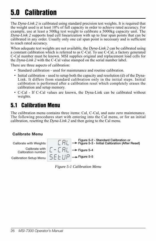
5.1 Calibration MenuThe calibration menu contains three items: Cal, C-Cal, and auto zero maintenance. The following procedures start with entering into the Cal menu, or for an initial calibration, resetting the Dyna-Link 2 and then going to the Cal menu.
Calibration Setup Menu
Calibrate with Weights
Calibrate withCalibration number
Calibrate MenuFigure 5-2 - Standard Calibration or Figure 5-3 - Initial Calibration (After Reset)
Figure 5-4
Figure 5-5
Figure 5-1 Calibration Menu
26 MSI-7300 Operator’s Manual
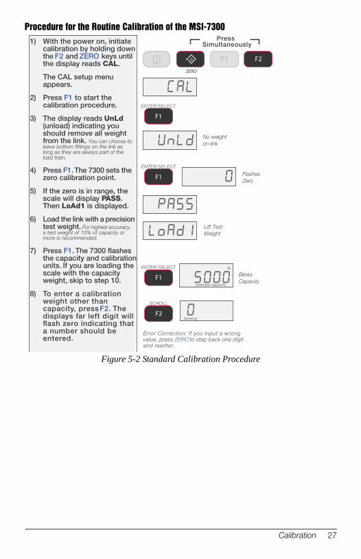
Procedure for the Routine Calibration of the MSI-7300
lb
Blinks
Capacity
1) With the power on, initiatecalibration by holding downthe F2 and ZERO keys untilthe display reads CAL.
The CAL setup menuappears.
2) Press F1 to start thecalibration procedure.
3) The display reads UnLd(unload) indicating youshould remove all weightfrom the link. You can choose toleave bottom fittings on the link aslong as they are always part of theload train.
4) Press F1. The 7300 sets thezero calibration point.
5) If the zero is in range, thescale will display PASS.Then LoAd1 is displayed.
6) Load the link with a precisiontest weight. For highest accuracy,a test weight of 10% of capacity ormore is recommended.
7) Press F1. The 7300 flashesthe capacity and calibrationunits. If you are loading thescale with the capacityweight, skip to step 10.
8) To enter a calibrationweight other thancapacity, press F2. Thedisplays far left digit willflash zero indicating thata number should beentered.
blinking
No weight
on link
Flashes
Zero
Lift Test
Weight
example capacity
Error Correction: If you input a wrongvalue, press ZERO to step back one digitand reenter.
ENTER/SELECT
F1
ENTER/SELECT
F1
ENTER/SELECT
F1
SCROLL
F2
PressSimultaneously
F20
ZERO
F1
Figure 5-2 Standard Calibration Procedure
Calibration 27

5 times
fixed
blinking blinking
blinking
blinking
blinking
blinking
fixed
fixed
fixed
9) Press the F2 key to scrollthe number and the F1key to enter each digit ofthe calibration weight.
In this example, we’ll enter 2500kg on a 5000 kg capacity scale.Do not push the F1 key two timesin a row.
To add a decimal point, push thePOWER key while the number isblinking.
10) When the entire value of thetest weight is displayed andthe weight and link arestable, press F1 to finish offthe weight entry. If theresultant cal value is withinlimits, the display will readPASS.
11) The display now readsLoAd2. The Dyna-Linkallows multi-pointcalibration. If more calpoints are desired (up tothree additional) press F2and repeat steps 8-10. Iffinished with span points,go to step 12.
12) Press ZERO to store thecalibration constants. TheLCD will read CAL’d toindicate the calibration isacceptable.
13) Skip to step 14, or press F1to observe the CAL number.The C-CAL numberappears. Make a note of thevalue.
14) Press ZERO to exitcalibration. The next menuitem Setup appears.
15) Press ZERO to store thecalibration and return tostandard link operation, orpress F1 if you want toadjust additional cal setupparameters (Standard, AZM, etc.)
You can cancel calibration by pressingPower and the scale will reset to theprevious calibration constants.
To add span
pointsGo to step 8
To complete
calibration
Next Cal menu item
SCROLL
F2
SCROLL
F2
SCROLL
F2
SCROLL
F2
SCROLL
F2
SCROLL
F2
F2
SCROLL
ENTER/SELECT
F1
ENTER/SELECT
F1
ENTER/SELECT
F1
ENTER/SELECT
F1
0
EXIT/SAVE
ZERO
0
EXIT/SAVE
ZERO
ENTER/SELECT
F1
Optional:to display
Cal number
ENTER/SELECT
F1blinking
Example Cal#
0
EXIT/SAVE
ZERO
Cal saved to memory
F1
Figure 5-2 Standard Calibration Procedure (continued)
28 MSI-7300 Operator’s Manual
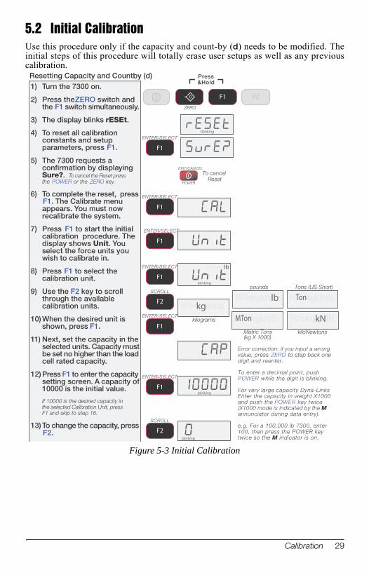
5.2 Initial CalibrationUse this procedure only if the capacity and count-by (d) needs to be modified. The initial steps of this procedure will totally erase user setups as well as any previous calibration.
1) Turn the 7300 on.
2) Press the ZERO switch andthe F1 switch simultaneously.
3) The display blinks rESEt.
4) To reset all calibrationconstants and setupparameters, press F1.
5) The 7300 requests aconfirmation by displayingSure?. To cancel the Reset pressthe POWER or the ZERO key.
6) To complete the reset, pressF1. The Calibrate menuappears. You must nowrecalibrate the system.
7) Press F1 to start the initialcalibration procedure. Thedisplay shows Unit. Youselect the force units youwish to calibrate in.
8) Press F1 to select thecalibration unit.
9) Use the F2 key to scrollthrough the availablecalibration units.
10) When the desired unit isshown, press F1.
11) Next, set the capacity in theselected units. Capacity mustbe set no higher than the loadcell rated capacity.
12) Press F1 to enter the capacitysetting screen. A capacity of10000 is the initial value.
If 10000 is the desired capacity inthe selected Calibration Unit, pressF1 and skip to step 16.
13) To change the capacity, pressF2.
Resetting Capacity and Countby (d)
blinking
blinking
blinking
blinking
Error correction: if you input a wrongvalue, press ZERO to step back onedigit and reenter.
To enter a decimal point, pushPOWER while the digit is blinking.
For very large capacity Dyna-LinksEnter the capacity in weight X1000and push the POWER key twice(X1000 mode is indicated by the Mannunciator during data entry).
e.g. For a 100,000 lb 7300, enter100, then press the POWER keytwice so the M indicator is on.
ENTER/SELECT
F1
ENTER/SELECT
F1
EXIT/CANCEL
POWER
To cancelReset
F1
ENTER/SELECT
F1
ENTER/SELECT
F1
SCROLL
F2
ENTER/SELECT
F1
ENTER/SELECT
F1
SCROLL
F2
kg lbM kNTon
Press&Hold
0
ZERO
F2F1
kg lbM kNTonkg lbM kNTon kg lbM kNTon
kg lbM kNTon kg lbM kNTon
pounds Tons (US Short)
Metric Tons(kg X 1000)
kiloNewtons
kilograms
kg lbM kNTonkg lbM kNTon kg lbM kNTon
kg lbM kNTon kg lbM kNTon
Figure 5-3 Initial Calibration
Calibration 29
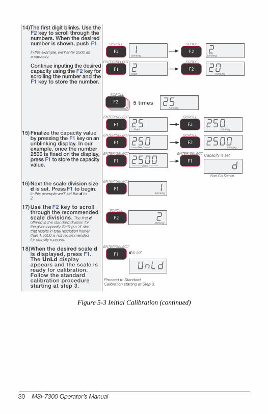
The first digit blinks. Use theF2 key to scroll through thenumbers. When the desirednumber is shown, push F1.In this example, we’ll enter 2500 asa capacity.
Continue inputing the desiredcapacity using the F2 key forscrolling the number and theF1 key to store the number.
fixed
blinking blinking
blinking
SCROLL
F2
SCROLL
F2
SCROLL
F2
ENTER/SELECT
F1
5 timesblinking
blinking
blinking
fixed
fixed
fixed
15) Finalize the capacity valueby pressing the F1 key on anunblinking display. In ourexample, once the number2500 is fixed on the display,press F1 to store the capacityvalue.
16) Next the scale division sized is set. Press F1 to begin.In this example we’ll set the d to2.
17) Use the F2 key to scrollthrough the recommendedscale divisions. The first doffered is the standard division forthe given capacity. Setting a ‘d’ sizethat results in total resolution higherthan 1:5000 is not recommendedfor stability reasons.
18)When the desired scale dis displayed, press F1.The UnLd displayappears and the scale isready for calibration.Follow the standardcalibration procedurestarting at step 3.
blinking
Capacity is set.
d is set.
Proceed to StandardCalibration starting at Step 3.
F2
SCROLL
ENTER/SELECT
F1
ENTER/SELECT
F1
ENTER/SELECT
F1
ENTER/SELECT
F1
SCROLL
F2
SCROLL
F2
ENTER/SELECT
F1
Next Cal Screen
blinking
SCROLL
F2
ENTER/SELECT
F1
14)
Figure 5-3 Initial Calibration (continued)
30 MSI-7300 Operator’s Manual
5.3 Guidelines for Capacity and ResolutionDyna-Links are subject to forces that static scales do not experience. Many bridge cranes, hoist cranes, and mobile cranes lack rigidity and tend to bounce or swing when loads are lifted. For this reason, MSI recommends that resolution is kept in the 1:2000 to 1:3000 range. Some improvement in stability can be achieved by increasing the filtering. However, you should never program resolution that is far greater than you need. If the MSI-7300 Dyna-Link 2 display is never stable, it is recommended that the resolution is reduced as well as filtering increased. In any circumstance, the resolution should never be set higher than 1:15000 due to temperature and noise considerations common to all strain gage based load cells. The tension must be stable for certain features to work: ZERO tension must be stable to be zeroed. TARE tension must be stable to be tared. TOTAL tension must be stable to be added to the total registers. One way to improve the stability is to increase the filtering, at the risk of increasing settling time. The other is to increase the ‘d’ (reduce resolution). The third way is to increase the motion window. The MSI-7300 Dyna-Link 2 defaults to ±1d as a motion window. It can be changed at MSI to a higher value if desired. Often ±3d is chosen for bridge cranes as these tend to have a lot of bounce to them. This of course carries an accuracy penalty adding ±3 d to the total accuracy of the Dyna-Link if the zero or tare operation happens to capture the tension in a valley or peak.Setting capacity is dictated primarily by the capability of the load cell. MSI supplies the MSI-7300 Dyna-Link 2 in many capacities. Never set the capacity of the Dyna-Link higher than the rating of the load cell. Due to the excellent linearity of the MSI Link load cell, it is acceptable to set lower capacities to better match the crane the MSI-7300 Dyna-Link 2 is used on. For example, if the hoist is rated for 9000lb, you can use a 10000 lb capacity Dyna-Link and reset the capacity to 9000 lb so that the Dyna-Link will indicate overload at 9000 lb instead of 100000 lb. Derating as much as 50% of the capacity is usually acceptable, but the Dyna-Link may be less stable if the ‘d’ is decreased (resolution increased).
NoteThe capacity of all the MSI-7300 systems is rated approximately 20% higher than the rated capacity in pounds. This is to allow the kg capacity to be exactly 1/2 the number of the pounds capacity.
Calibration 31
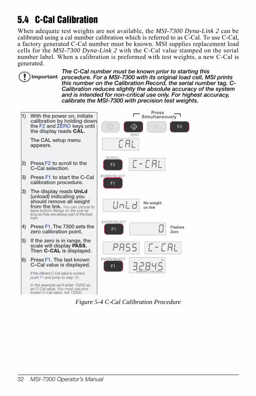
5.4 C-Cal CalibrationWhen adequate test weights are not available, the MSI-7300 Dyna-Link 2 can be calibrated using a cal number calibration which is referred to as C-Cal. To use C-Cal, a factory generated C-Cal number must be known. MSI supplies replacement load cells for the MSI-7300 Dyna-Link 2 with the C-Cal value stamped on the serial number label. When a calibration is preformed with test weights, a new C-Cal is generated.
ImportantThe C-Cal number must be known prior to starting this procedure. For a MSI-7300 with its original load cell, MSI prints this number on the Calibration Record, the serial number tag. C-Calibration reduces slightly the absolute accuracy of the system and is intended for non-critical use only. For highest accuracy, calibrate the MSI-7300 with precision test weights.
1) With the power on, initiatecalibration by holding downthe F2 and ZERO keys untilthe display reads CAL.
The CAL setup menuappears.
2) Press F2 to scroll to theC–Cal selection.
3) Press F1 to start the C-Calcalibration procedure.
3) The display reads UnLd(unload) indicating youshould remove all weightfrom the link. You can choose toleave bottom fittings on the Link aslong as they are always part of the loadtrain.
4) Press F1. The 7300 sets thezero calibration point.
5) If the zero is in range, thescale will display PASS.Then C-CAL is displayed.
6) Press F1. The last knownC–Cal value is displayed.
If the offered C-Cal value is correct,push F1 and jump to step 10.
In this example we’ll enter 15200 asan C-Cal value. You must use yourknown C-Cal value, not 15200.
No weighton link
FlashesZero
ENTER/SELECT
F1
ENTER/SELECT
F1
SCROLL
F2
lb
example C-Cal Value
ENTER/SELECT
F1
PressSimultaneously
F20
ZERO
F1
Figure 5-4 C-Cal Calibration Procedure
32 MSI-7300 Operator’s Manual

7) To input the C-Cal value,press F2 to start the numberentry process.
8) Use F2 to change thenumber, and F1 to enterthe number. Add the nextdigit by pushing F2 andscrolling as required.Repeat this sequenceuntil the entire C-Calnumber is entered.
5 times
fixed
blinking blinking
blinking
blinking
SCROLL
F2
SCROLL
F2
SCROLL
F2
F2
SCROLL
ENTER/SELECT
F1
Error Correction: If you input a wrong value, press ZERO to stepback one digit and reenter.
To input a decimal point, push POWER while a digit is blinking.
F1
9) Once the entire C-Calvalue is entered, pressF1 to finalize the number.The 7300 modifies itsspan factor registers toadjust the calibration tothe value of the C-Cal. Ifthe C-Cal input was inthe acceptable range, theLCD will read PASS.
Multiple C-Cal span points arepossible, but are onlyaccessible using MSI’soptional SCCMP program.
10) When the final C-Calnumber is finished, pressZERO to exit and savethe new C-Calcalibration. The LCDreads STORE toindicate a successfulcalibration.
11) Press ZERO again to exitthe CAL menu and startstandard link tensionoperation.
blinking
blinking
fixed
fixed
fixed
SCROLL
F2
SCROLL
F2
ENTER/SELECT
F1
ENTER/SELECT
F1
ENTER/SELECT
F1
ENTER/SELECT
F1
blinking
SCROLL
F2SCROLL
F2blinking
0
EXIT/SAVE
ZERO
0
EXIT/SAVE
ZERO
SCROLL
F2blinking
Figure 5-4 C-Cal Calibration Procedure (continued)
Calibration 33
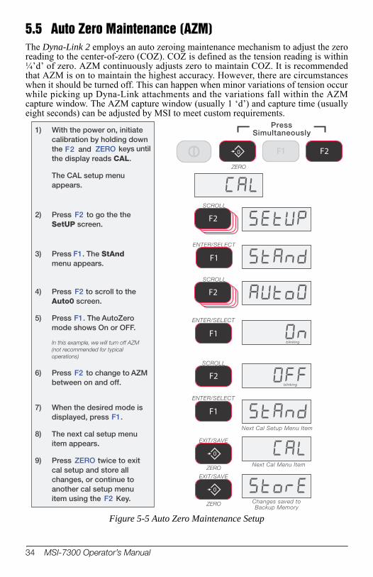
5.5 Auto Zero Maintenance (AZM)The Dyna-Link 2 employs an auto zeroing maintenance mechanism to adjust the zero reading to the center-of-zero (COZ). COZ is defined as the tension reading is within ¼’d’ of zero. AZM continuously adjusts zero to maintain COZ. It is recommended that AZM is on to maintain the highest accuracy. However, there are circumstances when it should be turned off. This can happen when minor variations of tension occur while picking up Dyna-Link attachments and the variations fall within the AZM capture window. The AZM capture window (usually 1 ‘d’) and capture time (usually eight seconds) can be adjusted by MSI to meet custom requirements.
1) With the power on, initiatecalibration by holding downthe F2 and ZERO keys untilthe display reads CAL.
The CAL setup menuappears.
2) Press F2 to go the theSetUP screen.
3) Press F1. The StAndmenu appears.
4) Press F2 to scroll to theAuto0 screen.
5) Press F1. The AutoZeromode shows On or OFF.
In this example, we will turn off AZM
(not recommended for typical
operations)
6) Press F2 to change to AZMbetween on and off.
7) When the desired mode isdisplayed, press F1.
8) The next cal setup menuitem appears.
9) Press ZERO twice to exitcal setup and store allchanges, or continue toanother cal setup menuitem using the F2 Key.
ENTER/SELECT
F1
F2
SCROLL
SCROLL
F2
ENTER/SELECT
F1
0
EXIT/SAVE
ZERO
blinking
PressSimultaneously
F20
ZERO
F1
ENTER/SELECT
F1blinking
F2
SCROLL
Next Cal Setup Menu Item
0
EXIT/SAVE
ZERO
Next Cal Menu Item
Changes saved toBackup Memory
Figure 5-5 Auto Zero Maintenance Setup
34 MSI-7300 Operator’s Manual

5.6 Service CountersThe MSI-7300 maintains two service counters for safety.
• The first counter counts the number of times the scale has been overloaded. • The second counter counts lifts above 25% of capacity.
These counters serve to warn the user to inspect the load train after a number of overloads, also when there is a chance of fatigue failure. The power up routine will be interrupted when the lift counter exceeds 16383 lifts or the overload counter exceeds 1023 overloads. If the screen displays LFCnt when unit is powered on :
1. Push TARE to display the 25% lift counter. 2. Push TARE again to see the overload lift counter. 3. Push the ZERO key to acknowledge the warning and return to standard scale
operation.
Note The power up warning message won't appear again for another 16383 lifts ( or 1023 overloads).
1) Program a user function key tobe TEST (see function key setup)For this example, F1isprogrammed as TEST.
2) Press F1- TEST .
3) Within two seconds of pressing theF1– TEST key, press F1 again(must be F1 regardless of which key is
programmed as TEST).
The test will sequence through steps 4
to 7 automatically unless you stop it by
pressing F2 immediately, then using
F1 and F2 each parameter can be
observed statically.
4) The display flashes LFCnt (forlift counter) followed by thenumber of times the weight hasexceeded 25% of capacity.
5) Next, the display flashes OLCnt(for overload counter) followedby the number of times theweight has exceeded capacity.
6) Next,the display flashes the C-Cal value.
7) The Dyna-Link returns tostandard weighing mode. If youinterrupted the auto sequence,press ZERO to return to tensionlink mode.
Return to standard weight display
ENTER/SELECT
F1
Number of Lifts above 25% of Capacity
Number of Lifts that exceeded Capacity
example value
example value
Start of Test Sequence
All segments on
blinking
blinking example C-Cal value
Fx
Figure 5-6 Access the Service Counters
WARNINGOnly a MSI factory representative can reset the service counters, as these are important safety warning features. Depending on the circumstances, a thorough load train inspection might be necessary to ensure user safety.
Reference MSI’s “Crane Scale Safety and Periodic Maintenance manual” (Pub. 243-08-94D) for proper loading techniques to improve the safety and longevity of your MSI-7300 crane scale. This publication is available at www.msiscales.com and is included in the CD shipped with your crane scale.
Calibration 35
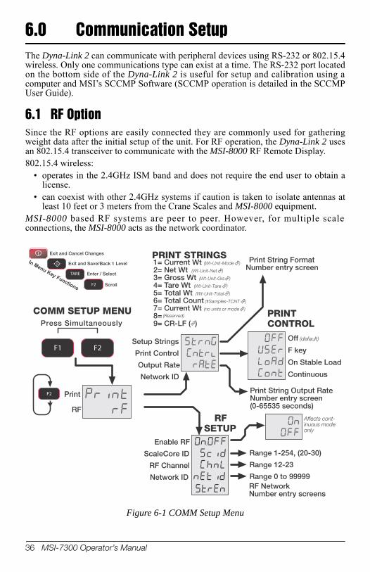
6.0 Communication SetupThe Dyna-Link 2 can communicate with peripheral devices using RS-232 or 802.15.4 wireless. Only one communications type can exist at a time. The RS-232 port located on the bottom side of the Dyna-Link 2 is useful for setup and calibration using a computer and MSI’s SCCMP Software (SCCMP operation is detailed in the SCCMP User Guide).
6.1 RF OptionSince the RF options are easily connected they are commonly used for gathering weight data after the initial setup of the unit. For RF operation, the Dyna-Link 2 uses an 802.15.4 transceiver to communicate with the MSI-8000 RF Remote Display. 802.15.4 wireless:
• operates in the 2.4GHz ISM band and does not require the end user to obtain a license.
• can coexist with other 2.4GHz systems if caution is taken to isolate antennas at least 10 feet or 3 meters from the Crane Scales and MSI-8000 equipment.
MSI-8000 based RF systems are peer to peer. However, for multiple scale connections, the MSI-8000 acts as the network coordinator.
Number entry screen0
TARE
F2
Exit and Cancel Changes
Exit and Save/Back 1 Level
Enter / Select
Scroll
In Menu Key Functions
PRINT STRINGS
Off (default)
F key
On Stable Load
Continuous
PRINTCONTROL
Print String Output RateNumber entry screen(0-65535 seconds)
Print String Format1= Current Wt (Wt-Unit-Mode )
2= Net Wt (Wt-Unit-Net )
3= Gross Wt (Wt-Unit-Grs )
4= Tare Wt (Wt-Unit-Tare )
5= Total Wt (Wt-Unit-Total )
6= Total Count (#Samples-TCNT )
7= Current Wt (no units or mode )
8= (Reserved)
9= CR-LF ( )
Affects cont-inuous modeonly
RF
COMM SETUP MENU
Enable RF
ScaleCore ID
RF Channel
Network ID
RFSETUP
Setup Strings
Print Control
Output Rate
Network ID
Range 1-254, (20-30)
Range 12-23
Range 0 to 99999RF NetworkNumber entry screens
F2
Press Simultaneously
F1 F2
Figure 6-1 COMM Setup Menu
36 MSI-7300 Operator’s Manual

6.2 Printer SetupThe RS-232 comm port is capable of outputing tension data. All the weight modes the Dyna-Link can measure are available in user formatted form. The control mode program is what causes the Dyna-Link 2 to print.
• USER – the assigned F-Key is pressed, then one transmission of the selected string type is output.
• On Load – when the tension on the link is stable, one transmission will output, then the tension must return to zero to enable another print to output.
• Continuous – program the interval in seconds up to 65,535 seconds. Setting the interval to 0 will set an interval as fast as the system can go. To disable printing, simply don’t program an F-Key to print and set the control to “USER” or turn the control mode to “OFF.”
PRINT STRINGS
Off (default)
F key
On Stable Load
Continuous
PRINT CONTROL
Print String Output RateNumber entry screen(0-65535 seconds)
ENTER/SELECT
F1
Print String FormatNumber entry screen
1= Current Wt (Wt-Unit-Mode ) 2= Net Wt (Wt-Unit-Net )
3= Gross Wt (Wt-Unit-Grs )
4= Tare Wt (Wt-Unit-Tare )
5= Total Wt (Wt-Unit-Total )
6= Total Count (#Samples-TCNT )
7= Current Wt (no units or mode )
8= (Reserved)
9= CR-LF ( )
0
ZERO
F1 F2
Affects continuous mode only
Press Simultaneously
Figure 6-2 Print Output Setup Menu
Communication Setup 37
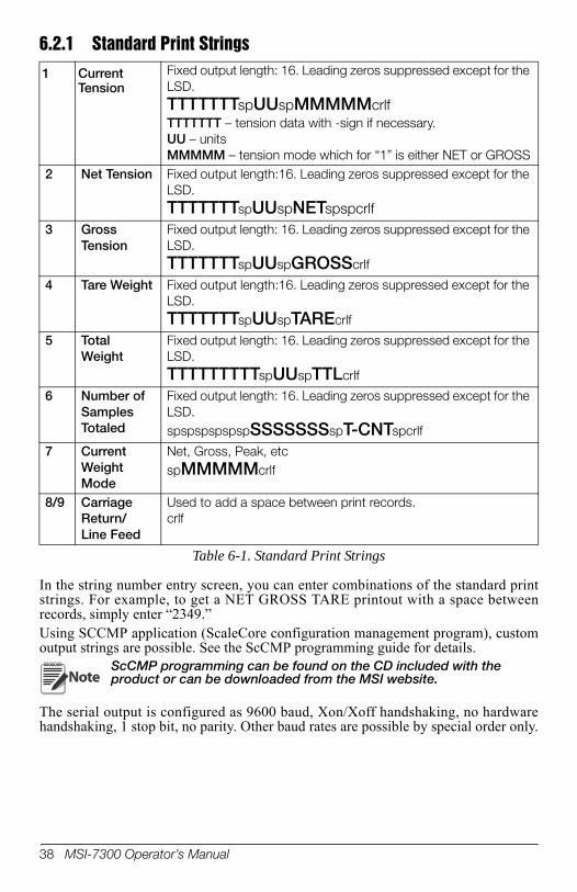
6.2.1 Standard Print Strings
1 Current Tension
Fixed output length: 16. Leading zeros suppressed except for the LSD.TTTTTTTspUUspMMMMMcrlfTTTTTTT – tension data with -sign if necessary. UU – unitsMMMMM – tension mode which for “1” is either NET or GROSS
2 Net Tension Fixed output length:16. Leading zeros suppressed except for the LSD. TTTTTTTspUUspNETspspcrlf
3 Gross Tension
Fixed output length: 16. Leading zeros suppressed except for the LSD.TTTTTTTspUUspGROSScrlf
4 Tare Weight Fixed output length:16. Leading zeros suppressed except for the LSD.TTTTTTTspUUspTAREcrlf
5 Total Weight
Fixed output length: 16. Leading zeros suppressed except for the LSD.TTTTTTTTTspUUspTTLcrlf
6 Number of Samples Totaled
Fixed output length: 16. Leading zeros suppressed except for the LSD.spspspspspspSSSSSSSspT-CNTspcrlf
7 Current Weight Mode
Net, Gross, Peak, etcspMMMMMcrlf
8/9 Carriage Return/Line Feed
Used to add a space between print records. crlf
Table 6-1. Standard Print Strings
In the string number entry screen, you can enter combinations of the standard print strings. For example, to get a NET GROSS TARE printout with a space between records, simply enter “2349.”Using SCCMP application (ScaleCore configuration management program), custom output strings are possible. See the ScCMP programming guide for details.
NoteScCMP programming can be found on the CD included with the product or can be downloaded from the MSI website.
The serial output is configured as 9600 baud, Xon/Xoff handshaking, no hardware handshaking, 1 stop bit, no parity. Other baud rates are possible by special order only.
38 MSI-7300 Operator’s Manual
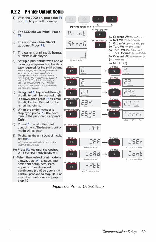
6.2.21) With the 7300 on, press the F1
and F2 key simultaneously.
2) The LCD shows Print. PressF1.
3) The submenu item StrnGappears. Press F1.
4) The current print mode formatnumber is displayed.
5) Set up a print format with one ormore digits representing the datatype required for the print output.In this example, we’ll set the print formatfor a net, gross, tare output with acarriage return/line feed between eachprint output. The number entry requiredwill be 2349. The 2 is for net weight,the 3 for gross weight, the 4 for tareweight, and the 9 inserts a space beforethe next print output.
6) Using the F2 Key, scroll throughthe digits until the desired digitis shown, then press F1 to enterthe digit value. Repeat for theremaining digits.
7) When the entire number isdisplayed press F1. The nextitem in the print menu appears,Cntrl.
8) Press F1 to enter the printcontrol menu. The last set controlmode will appear.
9) To change the print control mode,press F2.In this example, we’ll set the print controlmode to continuous.
10) Press F2 key until the desiredprint control mode is shown.
11) When the desired print mode isshown, push F1 to save. Thenext print setup item, rAteappears. If you have setcontinuous (cont) as your printcontrol, proceed to step 12). Forany other control mode jump tostep 15
0
ZERO
F1 F2
Press and Hold
blinking
blinking
fixed
fixed
fixed
ENTER/SELECT
F1
ENTER/SELECT
F1
ENTER/SELECT
F1
Next Print Menu Item
ENTER/SELECT
F1
ENTER/SELECT
F1
blinking
SCROLL
F2
SCROLL
F2
ENTER/SELECT
F1
ENTER/SELECT
F1fixed
blinking
SCROLL
F2
SCROLL
F2
Example Value
blinking
SCROLL
F2blinking
ENTER/SELECT
F1
SCROLL
F2SCROLL
F2
Function Key PrintsPrint is disabled
SCROLL
F2SCROLL
F2
Function Key PrintsPrint is disabled
Next Print Menu Item
ENTER/SELECT
F1
1= Current Wt (Wt-Unit-Mode )
2= Net Wt (Wt-Unit-Net )
3= Gross Wt (Wt-Unit-Grs )
4= Tare Wt (Wt-Unit-Tare )
5= Total Wt (Wt-Unit-Total )
6= Total Count (#Samples-TCNT )
7= Current Wt (no units or mode )
8= (Reserved)
9= CR-LF ( )
Printer Output Setup
Figure 6-3 Printer Output Setup
Communication Setup 39
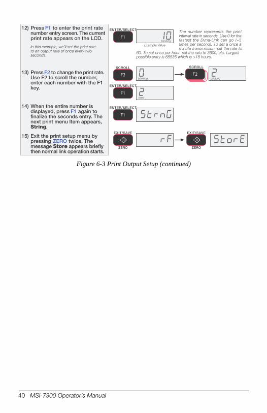
12) Press F1 to enter the print ratenumber entry screen. The currentprint rate appears on the LCD.
In this example, we’ll set the print rateto an output rate of once every twoseconds.
13) Press F2 to change the print rate.Use F2 to scroll the number,enter each number with the F1key.
14) When the entire number isdisplayed, press F1 again tofinalize the seconds entry. Thenext print menu Item appears,String.
15) Exit the print setup menu bypressing ZERO twice. Themessage Store appears brieflythen normal link operation starts.
ENTER/SELECT
F1blinking
Example Value
blinking
SCROLL
F2blinking
fixed
ENTER/SELECT
F1
SCROLL
F2
ENTER/SELECT
F1
0
EXIT/SAVE
ZERO
0
EXIT/SAVE
ZERO
The number represents the printinterval rate in seconds. Use 0 for thefastest the Dyna-Link can go (~5times per second). To set a once aminute transmission, set the rate to
60. To set once per hour, set the rate to 3600, etc. Largestpossible entry is 65535 which is >18 hours.
Figure 6-3 Print Output Setup (continued)
40 MSI-7300 Operator’s Manual
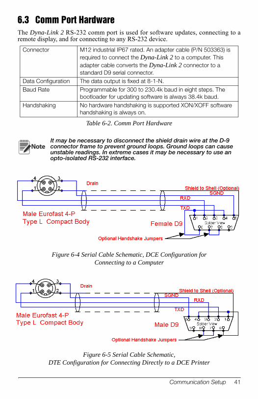
6.3 Comm Port HardwareThe Dyna-Link 2 RS-232 comm port is used for software updates, connecting to a remote display, and for connecting to any RS-232 device.
Table 6-2. Comm Port Hardware
Connector M12 industrial IP67 rated. An adapter cable (P/N 503363) is required to connect the Dyna-Link 2 to a computer. This adapter cable converts the Dyna-Link 2 connector to a standard D9 serial connector.
Data Configuration The data output is fixed at 8-1-N.Baud Rate Programmable for 300 to 230.4k baud in eight steps. The
bootloader for updating software is always 38.4k baud.Handshaking No hardware handshaking is supported XON/XOFF software
handshaking is always on.
It may be necessary to disconnect the shield drain wire at the D-9 connector frame to prevent ground loops. Ground loops can cause unstable readings. In extreme cases it may be necessary to use an opto-isolated RS-232 interface.
Note
Figure 6-4 Serial Cable Schematic, DCE Configuration for Connecting to a Computer
Figure 6-5 Serial Cable Schematic, DTE Configuration for Connecting Directly to a DCE Printer
Communication Setup 41
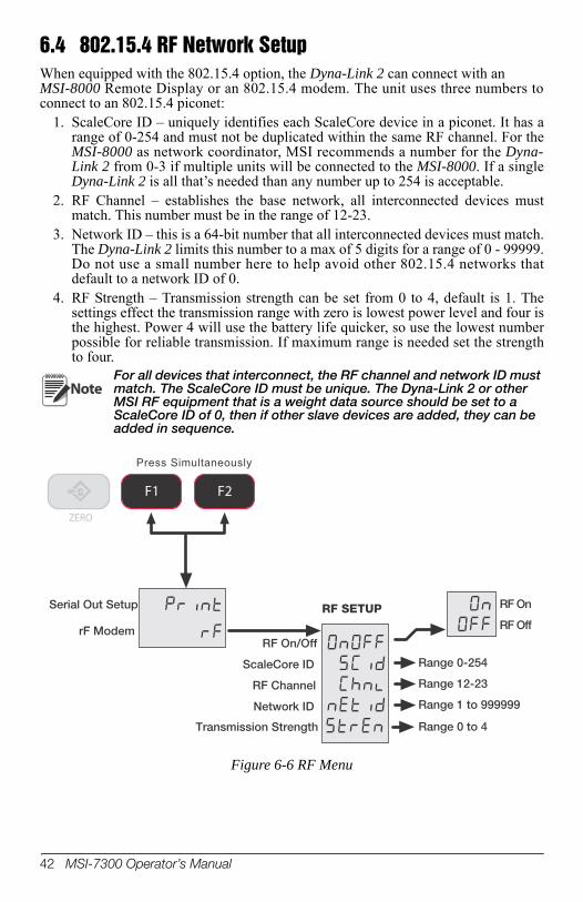
6.4 802.15.4 RF Network SetupWhen equipped with the 802.15.4 option, the Dyna-Link 2 can connect with an MSI-8000 Remote Display or an 802.15.4 modem. The unit uses three numbers to connect to an 802.15.4 piconet:
1. ScaleCore ID – uniquely identifies each ScaleCore device in a piconet. It has a range of 0-254 and must not be duplicated within the same RF channel. For the MSI-8000 as network coordinator, MSI recommends a number for the Dyna-Link 2 from 0-3 if multiple units will be connected to the MSI-8000. If a single Dyna-Link 2 is all that’s needed than any number up to 254 is acceptable.
2. RF Channel – establishes the base network, all interconnected devices must match. This number must be in the range of 12-23.
3. Network ID – this is a 64-bit number that all interconnected devices must match. The Dyna-Link 2 limits this number to a max of 5 digits for a range of 0 - 99999. Do not use a small number here to help avoid other 802.15.4 networks that default to a network ID of 0.
4. RF Strength – Transmission strength can be set from 0 to 4, default is 1. The settings effect the transmission range with zero is lowest power level and four is the highest. Power 4 will use the battery life quicker, so use the lowest number possible for reliable transmission. If maximum range is needed set the strength to four.
Serial Out Setup
rF ModemRF On/Off
ScaleCore ID
RF Channel
Network ID
RF On
RF OffRF SETUP
Range 0-254
Range 12-23
Range 1 to 999999
0
ZERO
F1 F2
Press Simultaneously
Transmission Strength Range 0 to 4
NoteFor all devices that interconnect, the RF channel and network ID must match. The ScaleCore ID must be unique. The Dyna-Link 2 or other MSI RF equipment that is a weight data source should be set to a ScaleCore ID of 0, then if other slave devices are added, they can be added in sequence.
Figure 6-6 RF Menu
42 MSI-7300 Operator’s Manual

RF Setup Procedure
example SCID Value
blinking blinking
Error Correction: If you input a wrong value, press ZERO to stepback one digit and reenter.
blinking
1) With the power on, open theCOMM setup menu bypressing the F1 and F2 keyssimultaneously.
The COMM setup menu
choice is Print.
2) Press F2 to scroll to the RFsetup menus.
3) Press F1 to enter the RFsetup menu.
4) The display reads OnOff
by pressing F1. If it is off,use the F2 key to change itto on. Then push F1.Off is only used when the 8000 ishardwired to a Dyna-Link.
5) Press F1. Next the Scid(ScaleCore ID) screen isshown
6) Press F1. The current SCIDnumber is shown.
If the offered SCID value is correct,
push F1 and jump to step 10.
In this example we’ll enter 3 as an SCIDnumber. Any value from 1-254 isacceptable. However, MSIrecommends a value from 20 – 30.
7) To input the SCID value,press F2 to start the numberentry process.
8) Use F2 to change thenumber, and F1 to enterthe number. Add the nextdigit by pushing F2 andscrolling as required.Repeat this sequenceuntil the entire SCIDnumber is entered.
9) Once the entire SCIDvalue is entered, press F1
10) The next RF setupparameter is “ChnL”(Channel). Press F1 to startthe number entry process.
11) The current RF channelnumber is displayed.If the offered RF Channel value iscorrect, push F1 and jump to step14.
SCROLL
F2
ENTER/SELECT
F1
ENTER/SELECT
F1
ENTER/SELECT
F1
ENTER/SELECT
F1
F2
F2
SCROLL
F2
ENTER/SELECT
F1
ENTER/SELECT
F1
Press Simultaneously
F1 F2
Figure 6-7 RF Setup Procedure
Communication Setup 43

12) Press F2 and using theprevious process, enterthe RF channel number.Recommended RF Channel numbersrange from 12 to 23. In this examplewe’ll use 21 as the RF Channel.
13) When the desired RFchannel number isshown and fixed, pressF1.
14) The next RF setup menuitem is the nEtid(Network ID). Press F1to see the current net IDnumber.If the offered network ID value iscorrect, push F1 and jump to step 17.
15) Using the numeric entryprocess as before, inputa network ID number.Press F2 to start a newnumber.Allowed network ID numbers rangefrom 0 to 99999. MSI recommendsa random number of at least fourdigits to ensure that the 8000system won’t conflict with anyother 802.11.4 networks (Zigbee).
16) When the final number isshown and fixed, pressF1 to store the networkID.
17) The RF setup menu goesto the first menu, OnOff.Press the ZERO key toexit out of the RF setupmenus.
18) Press ZERO again to exitthe COMM setup menuand store the new RFnetwork numbers.
blinking
blinking fixed
blinking
blinking
fixed
current Net ID blinking
blinking
example value only
SCROLL
F2
SCROLL
F2
SCROLL
F2
SCROLL
F2
SCROLL
F2
ENTER/SELECT
F1
ENTER/SELECT
F1
ENTER/SELECT
F1
ENTER/SELECT
F1
ENTER/SELECT
F1
Repeat numberentry procedure
ENTER/SELECT
F1
0
EXIT/SAVE
ZERO
0
EXIT/SAVE
ZERO
blinking
ENTER/SELECT
F117) The menu displays StrEn.
Press the F1 to enter.
Press F2, using the numeric entry process, input a transmission strength number.
16) When the desired numberis displayed, press F1 to store the number.
18)
When setting , use the lowest setting
possible to achieve the transmission required. Both the Scale/Dyna-Link and the 8000 should be set at the same transmission strength setting.
Note
RF Setup Procedure (continued)
44 MSI-7300 Operator’s Manual

6.5 FCC Statement (For 802.15.4 Option)Contains FCC ID: OUR-XBEEPROThe enclosed device complies with part 15 of the FCC rules. Operation is subject to the following two conditions: (i.) this device may not cause harmful interference and (ii.) this device must accept any interference received, including interference that may cause undesired operation.
6.6 International RF CERTS (For 802.15.4 Option)Canada Radio Cert. No.: IC: 4214A-XBEEPROAustralia & New Zealand: AS4268:3000Japan: Certificate of Radio Equipment in Japan No.: 08215111/AA/02Europe and much of Asia:
This product is compliant with the following standards and/or other normative documents:Safety (article 3.1A) EN60950-1:2001
EMC (article 3.1b) ETSI EN 301 489-1 v1.7.1 (2007-04) In accordance with the specific requirements of ETSI EN 301 489-17 v1.2.1 (2002-08)
Spectrum (article 3.2) ETSI EN 300 328 v1.7.1 (2006-10)
Communication Setup 45
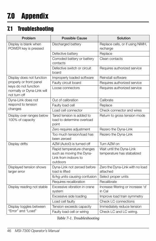
7.0 Appendix
7.1 TroubleshootingProblem Possible Cause Solution
Display is blank when POWER key is pressed
Discharged battery Replace cells, or if using NiMH, recharge
Defective battery ReplaceCorroded battery or battery contacts
Clean contacts
Defective switch or circuit board
Requires authorized service
Display does not function properly or front panel keys do not function normally or Dyna-Link will not turn off
Improperly loaded software Reinstall softwareFaulty circuit board Requires authorized serviceLoose connectors Requires authorized service
Dyna-Link does not respond to tension changes
Out of calibration CalibrateFaulty load cell ReplaceLoad cell connector Check connector and wires
Display over ranges below 100% of capacity
Tared tension is added to load to determine overload point
Return to gross tension mode
Zero requires adjustment Rezero the Dyna-LinkToo much tension/load has been zeroed
Rezero the Dyna-Link
Display drifts AZM (Auto0) is turned off Turn AZM onRapid temperature changes such as moving the Dyna-Link from indoors to outdoors
Wait until the Dyna-Link temperature has stabalized
Displayed tension shows larger error
Dyna-Link not zeroed before load is lifted
Zero the Dyna-Link with no load attached
lb/kg units causing confusion Select proper unitsRequires recalibration Recalibrate
Display reading not stable Excessive vibration in crane system
Increase filtering or increase ‘d’ in Cal
Excessive side loading Improve load train symmetryLoad cell faulty Check LC connections
Display toggles between “Error” and “Load”
Tension exceeds capacity Immediately reduce tension Faulty load cell or wiring Check LC and LC wiring.
Table 7-1. Troubleshooting
46 MSI-7300 Operator’s Manual
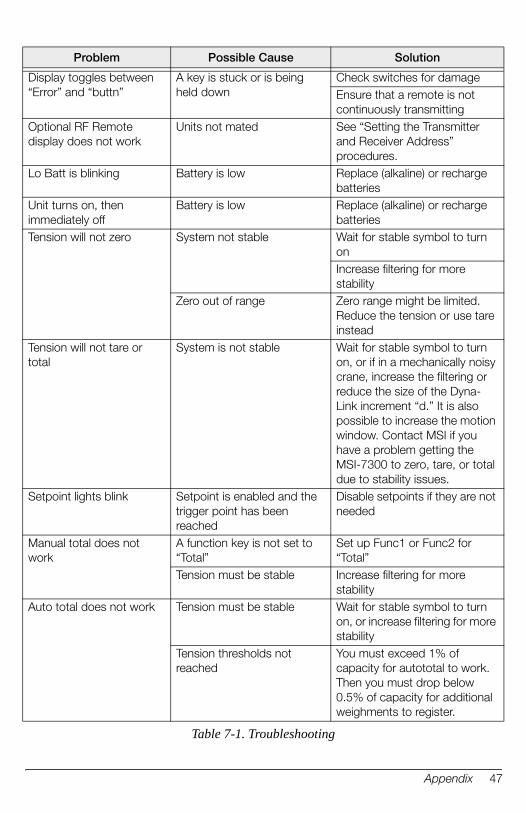
Display toggles between “Error” and “buttn”
A key is stuck or is being held down
Check switches for damageEnsure that a remote is not continuously transmitting
Optional RF Remote display does not work
Units not mated See “Setting the Transmitter and Receiver Address” procedures.
Lo Batt is blinking Battery is low Replace (alkaline) or recharge batteries
Unit turns on, then immediately off
Battery is low Replace (alkaline) or recharge batteries
Tension will not zero System not stable Wait for stable symbol to turn onIncrease filtering for more stability
Zero out of range Zero range might be limited. Reduce the tension or use tare instead
Tension will not tare or total
System is not stable Wait for stable symbol to turn on, or if in a mechanically noisy crane, increase the filtering or reduce the size of the Dyna-Link increment “d.” It is also possible to increase the motion window. Contact MSI if you have a problem getting the MSI-7300 to zero, tare, or total due to stability issues.
Setpoint lights blink Setpoint is enabled and the trigger point has been reached
Disable setpoints if they are not needed
Manual total does not work
A function key is not set to “Total”
Set up Func1 or Func2 for “Total”
Tension must be stable Increase filtering for more stability
Auto total does not work Tension must be stable Wait for stable symbol to turn on, or increase filtering for more stability
Tension thresholds not reached
You must exceed 1% of capacity for autototal to work. Then you must drop below 0.5% of capacity for additional weighments to register.
Problem Possible Cause Solution
Table 7-1. Troubleshooting
Appendix 47
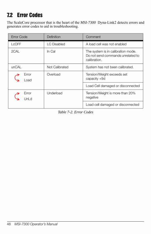
7.2 Error CodesThe ScaleCore processor that is the heart of the MSI-7300 Dyna-Link2 detects errors and generates error codes to aid in troubleshooting.
Table 7-2. Error Codes
Error Code Definition Comment
LcOFF LC Disabled A load cell was not enabled
2CAL In Cal The system is in calibration mode. Do not send commands unrelated to calibration.
unCAL Not Calibrated System has not been calibrated.
Error
Load
Overload Tension/Weight exceeds set capacity +9d
Load Cell damaged or disconnected
Error
UnLd
Underload Tension/Weight is more than 20% negative
Load cell damaged or disconnected
48 MSI-7300 Operator’s Manual

7.3
5000 lbs / 2500 KGMAXIMUM CAPACITY
7300lb
B
C = DIA.
E = LOAD CELL BODY WIDTH AT SHACKLE INTERFACE.
A
D
GF
Mechanical Dimensions
Figure 7-1. Mechanical Dimensions
Table 7-3. Mechanical Dimensions
Capacity A B C D E F GApprox
Shipping Wt
Shackle
1000 lb 8.0 in 13.53 in .75 in 5 in .99 in 1.69 in 1.75 in 4.4 lb G-2130 3.25T
500 kg 203 mm 344 mm 19 mm 127 mm 25 mm 43 mm 44.4 mm 2.0 kg
2500 lb 8.5 in 14.03 in .75 in 5 in .99 in 1.69 in 1.75 in 4.9 lb G-2130 3.25T
1250 kg 216 mm 356 mm 19 mm 127 mm 25 mm 43 mm 44.4 mm 2.2 kg
5000 lb 8.5 in 14.03 in .75 in 5 in .99 in 1.69 in 1.75 in 4.9 lb G-2130 3.25T
2500 kg 216 mm 356 mm 19 mm 127 mm 25 mm 43 mm 44.4 mm 2.2 kg
10,000 lb 8.5 in 16.14 in 1 in 5.50 in 1.35 in 2.28 in 2.34 in 7.3 lb G-2130 6.5T
5000 kg 216 mm 410 mm 25 mm 140 mm 34 mm 58 mm 59.4 mm 3.3 kg
25,000 lb 9.5 in 22.66 in 1.63 in 6.38 in 2.24 in 3.88 in 4.69 in 13 lb G-2130 17T
12,500 kg 241 mm 576 mm 41 mm 162 mm 57 mm 99 mm 119 mm 5.9 kg
50,000 lb 9.63 in 25.67 in 2 in 7.50 in 2.74 in 5.00 in 5.75 in 23 lb G-2130 25T
25,000 kg 245 mm 652 mm 51 mm 191 mm 70 mm 127 mm 146 mm 10 kg
100,000 lb 12 in 29.75 in 2.25 in 8.13 in 3.11 in 5.75 in 4.81 in 53 lb G-2140 55T
50,000 kg 305 mm 756 mm 57 mm 207 mm 79 mm 146 mm 122 mm 24 kg
Appendix 49

7.4 Firmware Update ProcedureUpdating firmware in the MSI-7300 requires the following: a DCE serial cable (MSI 503363-001, or build per DCE cable schematic on page 22), a PC with a terminal program (“Teraterm Pro” recommended), and if the PC does not have standard RS-232 serial ports, then a USB to serial converter. Make sure the driver for the USB converter is properly installed, and that the terminal program is set up for the proper comm port.The latest firmware code is available from the MSI service department and can be emailed on request. Your firmware version is displayed when the MSI-7300 is turned on in the form of “01-04” (your version will vary). Most firmware updates do not require a recallibration. Consult the version release notes for confirmation.
1. Setup the terminal serial port to 8 data bits, no parity, 1 stop bit, 9600 BAUD, XON/XOFF (flow control).
2. Connect to the Dyna-Link serial port using the DCE cable. Connect the D9 connector to your PC or USB adapter.
3. (Optional) Test that you have a connection by typing 00FF01?. If the connection is good the Dyna-Link will respond with 000001r2;0;01E02;2011-07-08;11:05 or something similar.
4. On the terminal keyboard, type ff0009=01995. Change the terminal serial port to 38400 BAUD. Hit the ‘q’ key to refresh the
display. Cycle Power on MSI-7300 by removing and reinstalling batteries. The following menu should appear
MSI-7300 SCALECORE 1 BOOT LOADER Ver. 02-04(c) 2011-09-02 17:06(u) Download and program application code (q) query app code info(g) execute app code(r) refresh
Your bootloader version may vary.
6. Type uTerminal should display:
Send File NOW, or press ^ to abort:
7. Send the .prg file using the file send feature of your terminal program. The character “#” will tick away as the ScaleCore programs.
Send File NOW, or press ^to abort:##################################### #################################################################################################################################################################################################################################################################Completed
Note
50 MSI-7300 Operator’s Manual
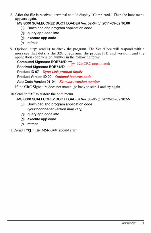
8. After the file is received, terminal should display “Completed.” Then the boot menu appears again.
MSI8000 SCALECORE2 BOOT LOADER Ver. 02-04 (c) 2011-09-02 16:06(u) Download and program application code(q) query app code info(g) execute app code(r) refresh
9. Optional step: send q to check the program. The ScaleCore will respond with a message that details the 32b checksum, the product ID and version, and the application code version number in the following form:
Computed Signature BOB742DReceived Signature BOB742DProduct ID 07 Dyna-Link product familyProduct Version ID 00 Optional features codeApp Code Version 01-04 Firmware version number
If the CRC Signature does not match, go back to step 4 and try again.
10.Send an “r” to restore the boot menu.MSI8000 SCALECORE2 BOOT LOADER Ver. 00-05 (c) 2012-05-02 10:55
(u) Download and program application code (your bootloader version may vary)
(q) query app code info(g) execute app code(r) refresh
11.Send a “g.” The MSI-7300 should start.
32b CRC must match
Appendix 51

The MSI Limited WarrantyMEASUREMENT SYSTEMS INTERNATIONAL, INC., WARRANTS load sensing elements and meters against defects in workmanship and materials for a period of one year from date of purchase and warrants electrical cables and batteries against the same defects for a period of ninety (90) days from date of purchase.
Any device which proves defective during the warranty period will be replaced or repaired at no charge; provided that the defective device is returned to the Company freight pre-paid.
In no event shall the Company be liable for the cost of any repairs or alterations made by others except those repairs or alterations made with its specific written consent, nor shall the Company be liable for any damages or delays whether caused by defective workmanship, materials or otherwise.
The Company shall not be liable for any personal injury or property damage resulting from the handling, possession or use of the equipment by the customer.
The warranty set forth herein is exclusive and is expressly in lieu of all other warranties, express or implied, including without limitation any implied warranties of merchantability or fitness, or of any other obligations or liability on the part of the Company.
The liability of the Company under this warranty is limited solely to repairing or replacing its products during the warranty periods; and the final judgment and disposition of all claims will be made by MEASUREMENT SYSTEMS INTERNATIONAL, INC.
52 MSI-7300 Operator’s Manual

Notes
Appendix 53

Notes
54 MSI-7300 Operator’s Manual


A RICE LAKE WEIGHING SYSTEMS COMPANY
Measurement SystemsInternational
TM
14240 Interurban Avenue South Suite 200 Seattle, WA 98168-4661 USAPhone: 206-433-0199 Fax: 206-244-8470
www.ricelake.com www.ricelake.mx www.ricelake.eu www.ricelake.co.in m.ricelake.com
© Rice Lake Weighing Systems 11/2013 152160 Rev B