lv - power quality products & solutions
TRANSCRIPT
LV - Power Quality Products & SolutionsCatalogue 2014

Our vision
We see a world where innovative individuals use collaborative solutions to make the most of their energy, while using less of our common planet
We enable people to experience and transform efficiency where they live and where they work, from home to enterprise to grid
Moving towards an active energy management architecture from Plant to Plug through EcoStruxure, because integration is the key to efficiency
> Schneider Electric in India
31Global Manufacturing Plants
10 +Distribution Centres
19000 +employees
1000 +R&D engineers in Bangalore
1Regional Project & Engineering Centre
1800 +Authorised Partners DistributorsSystem Integrators, Panel Builders

Your requirements….
Our solutions….
Optimize energy consumption�• By reducing electricity bills•�By reducing power losses•�By reducing CO2 emissions
Increase the power availability• Compensate for voltage sags detrimental to process operation•�Avoid nuisance tripping and supply interruptions
Improve your business performance�• Optimize the installation size•�Reduce harmonic distortion to avoid the premature ageing of equipment
and destruction of sensitive components
Reactive energy managementIn electrical networks, reactive energy is responsible for increased line currents, for a given active energy transmitted to loads.
The main consequences are•�Necessary over sizing of transmission and
distribution networks by the Utilities•� Increased voltage drops and sags along the
distribution lines•�Additional power losses
This is resulting in increased electricity bills for industrial customers because of•�Penalties applied by most Utilities to reactive
energy,•� Increased overall kVA demand,•� Increased energy consumption within the
installations.
Reactive energy management aims to optimize your electrical installation by reducing energy consumption, and improve power availability. CO2 emissions are also globally reduced.
5 to 10%reduction in utility power bills
Reduce energy costby improving electrical networks
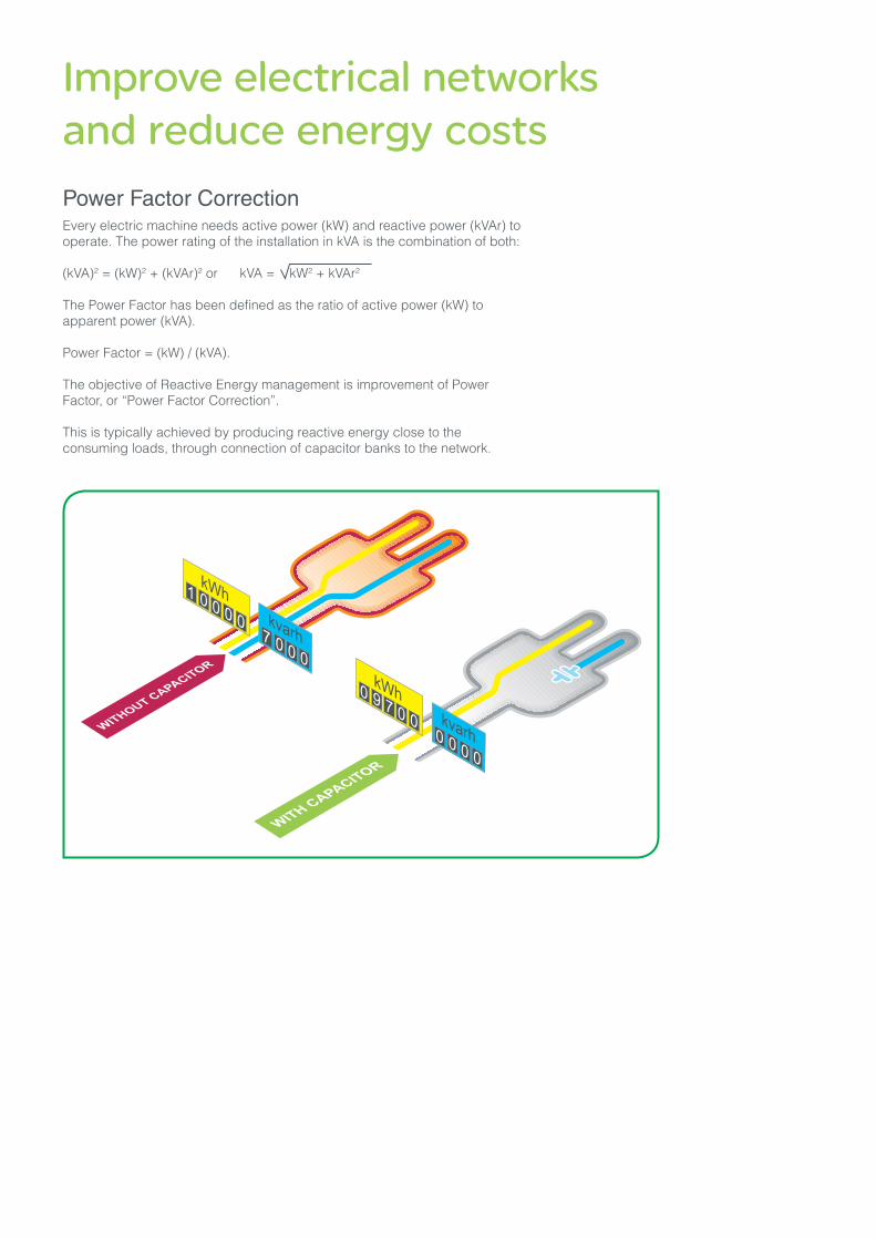
Improve electrical networks and reduce energy costs Power Factor CorrectionEvery electric machine needs active power (kW) and reactive power (kVAr) to operate. The power rating of the installation in kVA is the combination of both:
(kVA)2 = (kW)2 + (kVAr)2 or kVA = kW2 + kVAr2
The Power Factor has been defined as the ratio of active power (kW) to apparent power (kVA).
Power Factor = (kW) / (kVA).
The objective of Reactive Energy management is improvement of Power Factor,�or�“Power�Factor�Correction”.
This is typically achieved by producing reactive energy close to the consuming loads, through connection of capacitor banks to the network.
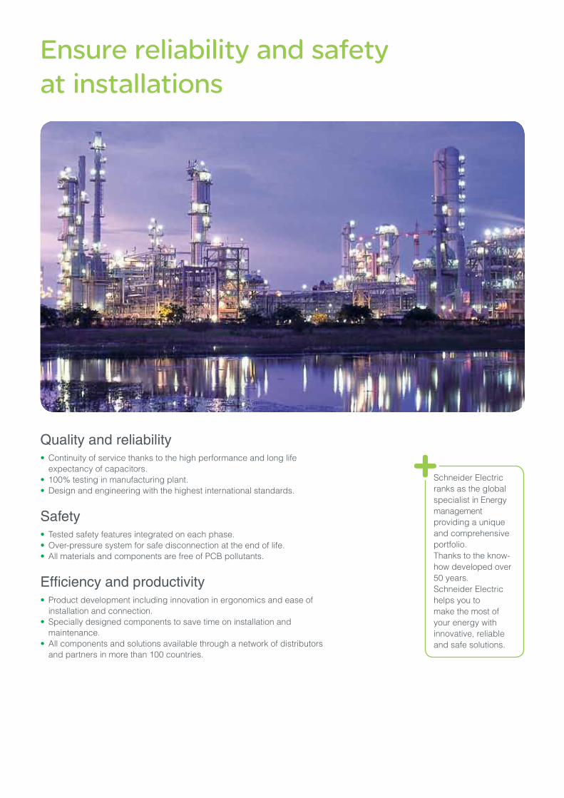
Ensure reliability and safety at installations
Quality and reliability�• Continuity of service thanks to the high performance and long life
expectancy of capacitors.• 100% testing in manufacturing plant.• Design and engineering with the highest international standards.
Safety• Tested safety features integrated on each phase. • Over-pressure system for safe disconnection at the end of life.• All materials and components are free of PCB pollutants.
Efficiency and productivity�• Product development including innovation in ergonomics and ease of
installation and connection.• Specially designed components to save time on installation and
maintenance.• All components and solutions available through a network of distributors
and partners in more than 100 countries.
Schneider Electric ranks as the global specialist in Energy management providing a unique and comprehensive portfolio. Thanks to the know-how developed over 50 years.Schneider Electric helps you to make the most of your energy with innovative, reliable and safe solutions.

Quality & Environment
Quality certified ISO9001 and ISO 14001A major strengthIn each of its manufacturing units, Schneider Electric has an operating organization whose main role is to verify quality and ensure compliance with standards. This procedure is:• Uniform for all departments;• Recognized by numerous customers and official organizations.
But, above all, its strict application has made it possible to obtain the recognition of independent organizations.
The quality system for design and manufacturing is certified in compliance with the requirements of the ISO9001 and ISO 14001 Quality Assurance model.
Stringent, systematic controlsDuring its manufacture, each equipment item undergoes systematic routine tests to verify its quality and compliance:• Measurement of operating capacity and tolerances;• Measurement of losses;• Dielectric testing;• Checks on safety and locking systems;• Checks on low-voltage components;• Verification of compliance with drawings and diagrams.
The results obtained are recorded and initialled by the Quality Control Department on the specific test certificate for each device.
RoHS, REAch complianceAll LV PFC components of Schneider Electric are RoHS , REAch compliant.
Schneider Electric undertakes to reduce the energy bill and CO2 emissions of its customers by proposing products, solutions and services which fit in with all levels of the energy value chain. The Power Factor Correction and harmonic filtering offer form part of the energy efficiency approach.
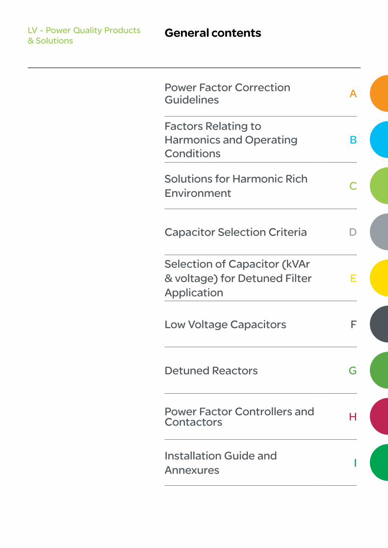
Power Factor Correction Guidelines A
Factors Relating to Harmonics and Operating Conditions
B
Solutions for Harmonic Rich Environment
C
Capacitor Selection Criteria D
Selection of Capacitor (kVAr & voltage) for Detuned Filter Application
E
Low Voltage Capacitors F
Detuned Reactors G
Power Factor Controllers and Contactors H
Installation Guide and Annexures
I
General contentsLV - Power Quality Products & Solutions


A-1
Power Factor Correction Guidelines
LV - Power Quality Products & Solutions
Why Reactive Energy Management? A-2
Method for Determining Compensation A-5

A-2
Power Factor Correction Guideline
Why reactive energy management?
Principle of reactive energy managementAll AC electrical networks consume two types of power: active power (kW) and reactive power (kVAr): •�The active power P (in kW) is the real power transmitted to loads such
as motors, lamps, heaters, computers, etc. The electrical active power is transformed into mechanical power, heat or light.
•�The reactive power Q (in kVAr) is used only to power the magnetic circuits of machines, motors and transformers.
The apparent power S (in kVA) is the vector combination of active and reactive power.
The circulation of reactive power in the electrical network has major technical and economic consequences. For the same active power P, a higher reactive power means a higher apparent power, and thus a higher current must be supplied.
The circulation of active power over time results in active energy (in kWh). The circulation of reactive power over time results in reactive energy (kvarh).
In an electrical circuit, the reactive energy is supplied in addition to the active energy.
For these reasons, there is a great advantage in generating reactive energy at the load level in order to prevent the unnecessary circulation of current�in�the�network.�This�is�what�is�known�as�“power factor correction”.�This is obtained by the connection of capacitors, which produce reactive energy in opposition to the energy absorbed by loads such as motors.
The result is a reduced apparent power, and an improved power factor P/S’�as�illustrated�in�the�diagram�opposite.
The power generation and transmission networks are partially relieved, reducing power losses and making additional transmission capacity available.
In this representation, the Power Factor (P/S) is equal to cosj.
QcQ
Power generation
Power generation
Transmission network
Transmission network
MotorActive energy Active energy
Reactive energy Reactive energy
Active energy Active energy
Reactive energyMotor
Capacitors
Power generation
Power generation
Transmission network
Transmission network
MotorActive energy Active energy
Reactive energy Reactive energy
Active energy Active energy
Reactive energyMotor
Capacitors
DE
9008
7.ep
s
DE
9008
8.ep
s
DE
9007
1_r.e
ps
DE
9007
1_r.e
ps
Reactive energy supplied and billed by the energy provider.
The reactive power is supplied by capacitors. No billing of reactive power by the energy supplier.
Due to this higher supplied current, the circulation of reactive energy in distribution networks results in:> Overload of
transformers> Higher
temperature rise in power cables
> Additional losses> Large voltage
drops> Higher energy
consumption and cost
> Less distributed active power.

A-3
Power Factor Correction Guideline
Why reactive energy management?
Benefits of reactive energy managementOptimized management of reactive energy brings economic and technical advantages.
Savings on the electricity bill> Eliminating penalties on reactive energy and decreasing kVA demand.> Reducing power losses generated in the transformers and conductors of
the installation.
Example:Loss reduction in a 630 kVA transformer PW = 6,500 W with an initial Power Factor = 0.7.With power factor correction, we obtain a final Power Factor = 0.98.The losses become: 3,316 W, i.e. a reduction of 49 %.
Increasing available powerA high power factor optimizes an electrical installation by allowing better use of the components. The power available at the secondary of a MV/LV transformer can therefore be increased by fitting power factor correction equipment on the low voltage side.
The table shows the increased available power at the transformer output through improvement of the Power Factor from 0.7 to 1.
ExampleCalculation for additional load in kW that can be connected by improving Power FactorLoad = 500 kVAInitial PF(cosφ1) = 0.7Target PF (cosφ2) = 0.95cosφ1 = kW1 / kVA1
kW1 = kVA x cosφ1
= 350 kWkW2 = kVA x cosφ2
= 475 kWAdditional kW that can be connected = 475 - 350 = 125 kW% of additional load = 125 / 350 x 100 = 36%
Power factor
Increasedavailablepower
0.7 0 %
0.8 + 14 %
0.85 + 21 %
0.90 + 28 %
0.95 + 36 %
1 + 43 %
A-4
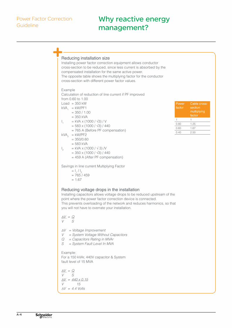
Reducing installation sizeInstalling power factor correction equipment allows conductorcross-section to be reduced, since less current is absorbed by thecompensated installation for the same active power.The opposite table shows the multiplying factor for the conductorcross-section with different power factor values.
ExampleCalculation of reduction of line current if PF improvedfrom 0.60 to 1.00Load = 350 kWkVA1 = kW/PF1 = 350 / 1.00 = 350 kVAI1 = kVA x (1000 / √3) / V = 583 x (1000 / √3) / 440 = 765 A (Before PF compensation)kVA2 = kW/PF2 = 350/0.60 = 583 kVAI2 = kVA x (1000 / √ 3) /V = 350 x (1000 / √3) / 440 = 459 A (After PF compensation)
Savings in line current Multiplying Factor = I1 / I2
= 765 / 459 = 1.67
Reducing voltage drops in the installationInstalling capacitors allows voltage drops to be reduced upstream of the point where the power factor correction device is connected. This prevents overloading of the network and reduces harmonics, so that you will not have to overrate your installation.
∆V = QV S
∆V = Voltage Improvement V = System Voltage Without CapacitorsQ = Capacitors Rating in MVArS = System Fault Level In MVA
Example:For a 150 kVAr, 440V capacitor & Systemfault level of 15 MVA
∆V = QV S∆V = 440 x 0.15V 15∆V = 4.4 Volts
Power factor
Cable cross-section multiplying factor
1 1
0.80 1.25
0.60 1.67
0.40 2.50
Power Factor Correction Guideline
Why reactive energy management?

A-5
Method for determining compensation
Step 1: Calculation of the required reactive powerThe objective is to determine the required reactive power Qc (kVAr) to be installed, in order to improve the power factor cos j and reduce the apparent power S.
For j’�<j, we obtain: cosj’�>�cosj and tan j’�<�tan�j.
This is illustrated in the diagram opposite.
Qc can be determined from the formula Qc = P. (tan j - tan j‘),�which�is�deduced from the diagram.Qc = power of the capacitor bank in kVAr.P = active power of the load in kW.tan j = tangent of phase shift angle before compensation.tan j’�=�tangent�of�phase�shift�angle�after�compensation.
The parameters j and tan j can be obtained from billing data, or from direct measurement in the installation.
The following table can be used for direct determination.
DE
9009
1.ep
s
Beforecompensation
Reactive power (kVAr) to be installed per kW of load, in order to get the required cos j’ or tan j’
tan j’ 0.75 0.62 0.48 0.41 0.33 0.23 0.00cos j’ 0.80 0.85 0.90 0.925 0.95 0.975 1.000
tan j cos j
1.73 0.5 0.98 1.11 1.25 1.32 1.40 1.50 1.73
1.02 0.70 0.27 0.40 0.54 0.61 0.69 0.79 1.02
0.96 0.72 0.21 0.34 0.48 0.55 0.64 0.74 0.96
0.91 0.74 0.16 0.29 0.42 0.50 0.58 0.68 0.91
0.86 0.76 0.11 0.24 0.37 0.44 0.53 0.63 0.86
0.80 0.78 0.05 0.18 0.32 0.39 0.47 0.57 0.80
0.75 0.80 0.13 0.27 0.34 0.42 0.52 0.75
0.70 0.82 0.08 0.21 0.29 0.37 0.47 0.70
0.65 0.84 0.03 0.16 0.24 0.32 0.42 0.65
0.59 0.86 0.11 0.18 0.26 0.37 0.59
0.54 0.88 0.06 0.13 0.21 0.31 0.54
0.48 0.90 0.07 0.16 0.26 0.48
Example: consider a 1000 kW motor with cos j = 0.8 (tan j = 0.75).In order to obtain cos j = 0.95, it is necessary to install a capacitor bank with a reactive power equal to k x P, i.e.: Qc = 0.42 x 1000 = 420 kVAr.
Total kVAr = kw x multiplying factor
The selection of Power Factor Correction equipment can follow a 4-step process:
Step - 1Calculation of the required reactive energy.
Step - 2Selection of the compensation mode: - Central, for the complete installation - By sector - For individual loads, such as large motors.
Step - 3Selection of the compensation type: - Fixed, by connection of a fixed-value capacitor bank; - Automatic, by connection of a number of steps, allowing adjustment
of the reactive energy to the required value; - Dynamic, for compensation of highly fluctuating loads.
Step - 4Factors relating to harmonics and operating conditions
Power Factor Correction Guideline

A-6
Step 2: Selection of the compensation modeThe location of low-voltage capacitors in an installation constitutes the mode of compensation, which may be central (one location for the entire installation), by sector (section-by-section), at load level, or some combination of the latter two. In principle, the ideal compensation is applied at a point of consumption and at the level required at any moment in time.
In practice, technical and economic factors govern the choice.
The location for connection of capacitor banks in the electrical network is determined by the:• overall objective (avoid penalties on reactive energy relieve transformer
or cables, avoid voltage drops and sags)•��Operating mode (stable or fluctuating loads)•��Foreseeable influence of capacitors on the network characteristics•��Installation cost.
1. Central compensation (CC)The capacitor bank is connected at the head of the installation to be compensated in order to provide reactive energy for the whole installation. This configuration is convenient for a stable and continuous load factor.
2. Group compensation (GC)/by SectorThe capacitor bank is connected at the head of the feeders supplying one particular sector to be compensated. This configuration is convenient for a large installation, with workshops having different load factors.
3. Compensation of individual loads (IC)/MotorsThe capacitor bank is connected right at the inductive load terminals (especially large motors). This configuration is very appropriate when the load power is significant compared to the subscribed power. This is the ideal technical configuration, as the reactive energy is produced exactly where it is needed, and adjusted to the demand.
Power Factor Correction Guideline
Supply Bus
Transformer
Circuit breaker
CC
GC GC
IC IC
M M M M
IC IC
CC : Central Compensation (APFC)GC : Group CompensationIC : Individual CompensationM : Motor Load
APFC Panel
CC
Method for determining compensation

A-7
Method for determining Compensation general the capacitor current should be less than or equal to 90% of no load current of the motor.
Capacitor rating in kVAr when motor speed (RPM)is:Motor 3000 rpm 1500 rpm 1000 rpm 750 rpm 500 rpm
Rating in HP
2.5 1 1 1.5 2 2.5
5 2 2 2.5 3.5 47.5 2.5 3 3.5 4.5 5.510 3 4 4.5 5.5 6.515 4 5 6 7.5 920 5 6 7 9 1225 6 7 9 10.5 14.530 7 8 10 12 1740 9 10 13 15 2150 11 12.5 16 18 2560 13 14.5 18 20 2870 15 16.5 20 22 3180 17 19 22 24 34
90 19 21 24 26 37
100 21 23 26 28 40110 23 25 28 30 43120 25 27 30 32 46130 27 29 32 34 49140 29 31 34 36 52145 30 32 35 37 54150 31 33 36 38 55155 32 34 37 39 56160 33 35 38 40 57165 34 36 39 41 59170 35 37 40 42 60175 36 38 41 43 61180 37 39 42 44 62185 38 40 43 45 63190 38 40 43 45 65200 40 42 45 47 67250 45 50 55 60 70
Recommended kVAr for 3 phase AC Inductor Motors (IC compensation)
Recommended kVAr for transformer No-Load compensationThe transformer works on the principle of Mutual Induction. The transformers will consume reactive power for magnetizing purpose. Following equivalent circuit of transformer provides the details of reactive power demand inside the transformer:
kVA rating of Transformer kVAr required forNo-Load compensation
Up to and including2000 kVA
2% of kVA rating
Power Factor Correction Guideline
Method for determining compensation
Thumb Rule:For motor kVAr = 1/3 of HP
Individual Compensation for Induction motors
From PCC
LV Bus
MCC
Note:Capacitor protection can be HRC Fuse / MCB or MCCB
M1 M2

A-8
Step 3: Selection of the compensation typeDifferent types of compensation should be adopted depending on the performance requirements and complexity of control:•�Fixed - by connection of a fixed-value capacitor bank•� Automatic - by connection of a different number of steps, allowing
adjustment of the reactive energy to the required value•�Dynamic - for compensation of highly fluctuating loads.
a) Fixed compensationThis arrangement uses one or more capacitor(s) to provide a constant level of compensation. Control may be:•�Manual: by circuit-breaker or load-break switch•�Semi-automatic: by contactor•�Direct connection to an appliance and switched with it.
These capacitors are installed:•�At the terminals of inductive loads (mainly motors)•� At busbars supplying numerous small motors and inductive appliances
for which individual compensation would be too costly•� In cases where the load factor is reasonably constant.
Power Factor Correction Guideline
Method for determining compensation
50 kVAr unit
A-9
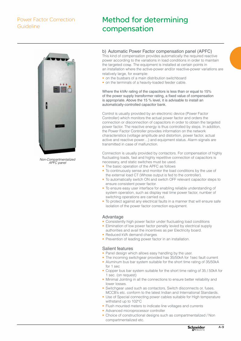
b) Automatic Power Factor compensation panel (APFC)This kind of compensation provides automatically the required reactive power according to the variations in load conditions in order to maintain the targeted cosj. The equipment is installed at certain points in an installation where the active-power and/or reactive-power variations are relatively large, for example:•� on the busbars of a main distribution switchboard• on the terminals of a heavily-loaded feeder cable.
Where the kVAr rating of the capacitors is less than or equal to 15% of the power supply transformer rating, a fixed value of compensation is appropriate. Above the 15 % level, it is advisable to install an automatically-controlled capacitor bank.
Control is usually provided by an electronic device (Power Factor Controller) which monitors the actual power factor and orders the connection or disconnection of capacitors in order to obtain the targeted power factor. The reactive energy is thus controlled by steps. In addition, the Power Factor Controller provides information on the network characteristics (voltage amplitude and distortion, power factor, actual active�and�reactive�power…)�and�equipment�status.�Alarm�signals�are�transmitted in case of malfunction.
Connection is usually provided by contactors. For compensation of highly fluctuating loads, fast and highly repetitive connection of capacitors is necessary, and static switches must be used.•� The basic operation of the APFC as follows•� To continuously sense and monitor the load conditions by the use of the external load CT (Whose output is fed to the controller).•� To automatically switch ON and switch OFF relevant capacitor steps to
ensure consistent power factor.•� To ensure easy user interface for enabling reliable understanding of
system operation, such as display real time power factor, number of switching operations are carried out.
•� To protect against any electrical faults in a manner that will ensure safe isolation of the power factor correction equipment.
Advantage•�Consistently high power factor under fluctuating load conditions•�Elimination of low power factor penalty levied by electrical supply
authorities and avail the incentives as per Electricity board.•�Reduced kVA demand charges•�Prevention of leading power factor in an installation.
Salient features•�Panel design which allows easy handling by the user.•��The incoming switchgear provided has 35/50kA for 1sec fault current•�Aluminum bus bar system suitable for the short time rating of 35/50kA
for 1 sec •��Copper bus bar system suitable for the short time rating of 35 / 50kA for
1 sec. (on request)•�Minimal Jointing in all the connections to ensure better reliability and
lower losses.•�Switchgear used such as contactors, Switch disconnects or, fuses, MCCB’s�etc.�conform�to�the�latest�Indian�and�International�Standards.
•�Use of Special connecting power cables suitable for High temperature withstand up to 102°C
•� Flush mounted meters to indicate line voltages and currents•�Advanced microprocessor controller •�Choice of constructional designs such as compartmentalized / Non
compartmentalized etc.
Power Factor Correction Guideline
Method for determining compensation
Non-Compartmentalized APFC panel

A-10
•�User friendly and aesthetically designed enclosure, designed and with IP42 enclosure.
•�Well engineered design to achieve optimal compensation with minimum step ratings.
•�Capacitor Duty contactor to reduce the inrush current to ensure the reliability of the capacitor.
•�Use of proper ventilated design ensures better reliability of the entire system.
Standard APFC Range available: 100 kVAr to 600 kVAr contactor switching
Applicable standardsIEC: 61921 (Power Capacitors- Low voltage power factor correction banks) is the international standard applicable for Low Voltage Power Factor Correction Banks and Automatic Power Factor Correction (APFC) equipments intended to be used for power factor correction purposes, equipped with built in switch gears and control gears. The guidelines for design, installation, operation and safety of APFC panels are followed based on this international standard.
The design of the Low Voltage Power Factor Correction banks and accessories comply with the following standards
•� IEC60831: Part 1 & 2-Shunt power capacitors of the self healing type for A.C systems having rated voltage up to and including 1kV.
•� IEC 60439-3: for low voltage switchgear and control gear assemblies. IEC 60947: Low Voltage Switchgear Part 2: Molded Case Circuit Breakers & Air circuit Breakers Part 4: Power Contactors Part 4-3: Thyristor Switch•� IEC 60269: LV Fuses•� IEC 60076-6 : Reactors•� IEC 60529: Degree of protection provided by enclosure (IP code)•� IEC 60044-1: Current transformers.•� IEC 60664-1 / IEC 61326: Power Factor Controller.
Power Factor Correction Guideline
Method for determining compensation
Compartmentalized APFC Panel
A-11
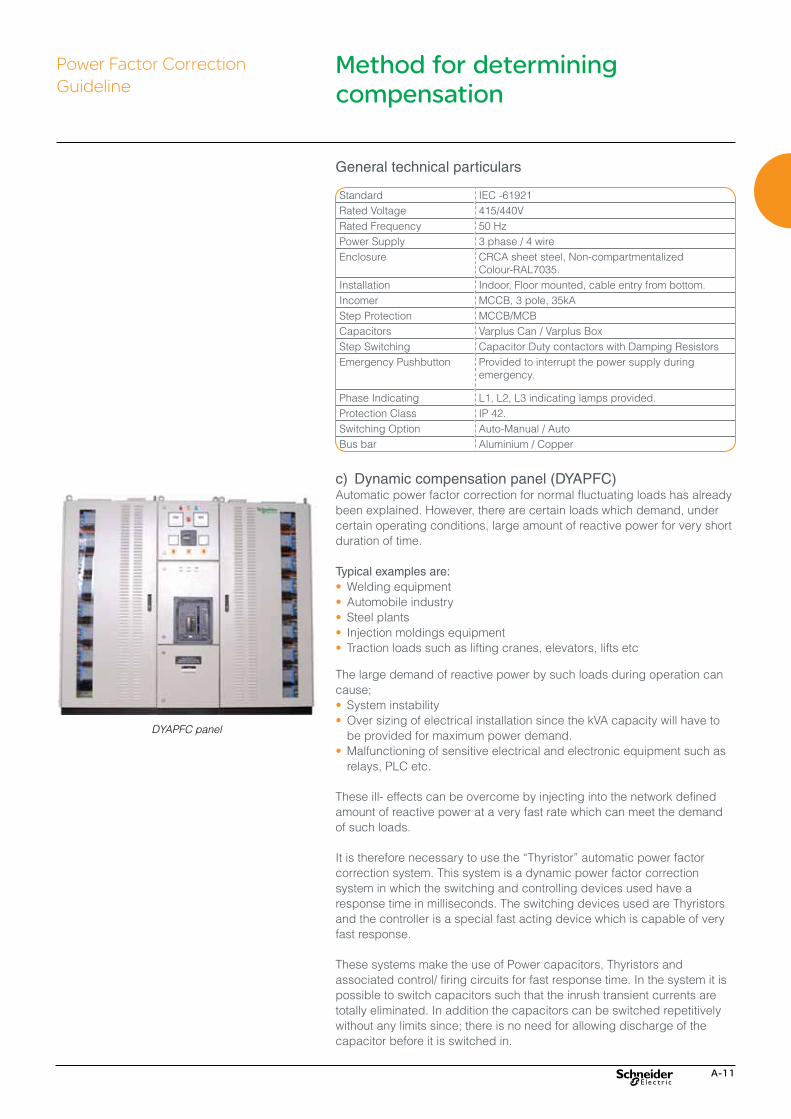
c) Dynamic compensation panel (DYAPFC)Automatic power factor correction for normal fluctuating loads has already been explained. However, there are certain loads which demand, under certain operating conditions, large amount of reactive power for very short duration of time.
Typical examples are:•�Welding equipment•�Automobile industry•�Steel plants•� Injection moldings equipment•� Traction loads such as lifting cranes, elevators, lifts etc
The large demand of reactive power by such loads during operation can cause;•�System instability•�Over sizing of electrical installation since the kVA capacity will have to
be provided for maximum power demand.•�Malfunctioning of sensitive electrical and electronic equipment such as
relays, PLC etc.
These ill- effects can be overcome by injecting into the network defined amount of reactive power at a very fast rate which can meet the demand of such loads.
It�is�therefore�necessary�to�use�the�“Thyristor”�automatic�power�factor�correction system. This system is a dynamic power factor correction system in which the switching and controlling devices used have a response time in milliseconds. The switching devices used are Thyristors and the controller is a special fast acting device which is capable of very fast response.
These systems make the use of Power capacitors, Thyristors and associated control/ firing circuits for fast response time. In the system it is possible to switch capacitors such that the inrush transient currents are totally eliminated. In addition the capacitors can be switched repetitively without any limits since; there is no need for allowing discharge of the capacitor before it is switched in.
Standard IEC -61921Rated Voltage 415/440VRated Frequency 50 HzPower Supply 3 phase / 4 wireEnclosure CRCA sheet steel, Non-compartmentalized
Colour-RAL7035.Installation Indoor, Floor mounted, cable entry from bottom. Incomer MCCB, 3 pole, 35kAStep Protection MCCB/MCBCapacitors Varplus Can / Varplus BoxStep Switching Capacitor Duty contactors with Damping ResistorsEmergency Pushbutton Provided to interrupt the power supply during
emergency.
Phase Indicating L1, L2, L3 indicating lamps provided.Protection Class IP 42.Switching Option Auto-Manual / AutoBus bar Aluminium / Copper
General technical particulars
Power Factor Correction Guideline
Method for determining compensation
DYAPFC panel

A-12

B-1
Factors Relating to Harmonics and Operating Conditions
LV - Power Quality Products & Solutions
Factors Relating to Harmonics and Operating Conditions B-2

B-2
What are Harmonics?Harmonics are sinusoidal current/voltage whose frequency is integral multiple of fundamental frequency. Harmonic currents are caused due to wave chopping/modification used in voltage/frequency converters. The flow of harmonic current through system impedance will create voltage harmonics. The superposition of harmonic voltage on incoming voltage will alter the incoming supply voltage waveform.
Loads can be classified in to two families:• Linear loads,• Non linear loads.
A load is said to be linear when its current has the same waveform as the applied voltage.. for ex: AC Motors, Incandescent lamps, Resistive heating elements, Inductors, Capacitors etc are linear loads.
A load is said to be non-linear when its current has different waveform as compared to applied voltage. Such as ... UPS, AC/DC Drives, Steel furnaces, Battery chargers etc.
Pictures are presented typical current waveforms for single-phase (top) and three-phase non linear loads (bottom).
Impact of non linear loads on R.M.S. currentThe presence of harmonic current will increase the total RMS current supplied to the load . For example : If the fundamental current of particular load is 100A, and the harmonic current is 30A in magnitude, then the total RMS current of this load will be about 4% higher than the fundamental current.
Higher RMS current due to harmonic will have impact on the total capacity of the feeder. This may call for over sizing of feeder, transformer, circuit breaker, power source etc, impacting Capital investment.
Single - Phase
Three - Phase
Factors relating to harmonics and operating conditions
Power Factor Correction Guideline
HARMONICS
1 3 5 7 9
Time
Fundamental3rd Harmonic5th Harmonic7th HarmonicResultant
Am
plit
ude

B-3
HeatingThe flow of harmonic current in conductors will increase the losses due to skin effect. The resistance of a conductor will increase with frequency, hence for high frequency harmonic current, the résistance offered by a conductor such as Bus bar, Cables, Circuit breakers etc will be higher, and consequently the heating will be more. This may call for over sizing Cables, bus bars, Circuit breakers, ventilation system, impacting capital investment.
Impact on active powerThe presence of harmonic current/voltage will increase the power consumption of rotating machines such as Induction motors, Generating sets due to pulsating/negative torque.
Impact on devices connected in series with non linear loadsConnected in series with non linear loads, we will find cables, circuit breaker, transformers. r.m.s. current will produce additional losses and these components may need to be oversized. This will increase the cost of the equipment. If the current at the front end of the manufacturing plant has a high content of harmonics, the incoming transformer will have to be oversized and the contract subscribed with the energy supplier will cost more.
Impact on devices connected in parallel with non linear loadsDistorted current is likely to produce a distorted voltage with severe consequences: devices connected to the network may trip and cause plant shutdown, or the current in capacitor bank, used to correct the power factor, can increase drastically. Eventually resonance may occur causing dangerous over voltages.
Economical consequences of harmonics The major consequences of harmonics are the increase of the r.m.s. current in the different circuits and the deterioration of the supply voltage quality. The negative impact may remain unnoticed, with economical adverse results.
That is why a proper harmonic mitigation will contribute to improve competitiveness of companies in different ways:• Reduced overloading on the electrical system, thereby releasing
useable capacity,• Reduced system losses and demand power,• Reduced risks of outage,• Extended equipment lifetime.
The total harmonic distortion THD is the usual parameter to evaluate the level of distortion of an alternating signal The voltage distortion THDv is usually considered at the installation level, while the current distortion THDi is usually considered at the non linear equipment level.
Factors relating to harmonics and operating conditions
Power Factor Correction Guideline

B-4

C-1
Solutions for Harmonic Rich Environment
LV - Power Quality Products & Solutions
Solutions for Harmonic Rich Environment C-2

C-2
Depending on the magnitude of harmonics in the network the different configurations shall be adopted • Harmonic Filters > Detuned Filters > Tuned Filters
• Active Filters > Three phase 3 wire > Three phase 4 wire
• Hybrid Filter > Combination of passive and activefilters. Active filters for harmonic
reduction and passive filter for PF improvement.
Detuned filters Detuned filters are the most preferred since they are cost effective solutions which work on the principle of avoiding resonance by achieving an inductive impedance at harmonic frequencies. The tuning frequency is generally lower than 90% of the lowest harmonic frequency whose amplitude is significant and which operate in a stable manner under various network configurations and operating conditions.
Detuned harmonic filter systems consist of Reactor(L) in series with a Capacitor (C) as shown in figure.
Fr = 1/(2¶ √ LC)
Tuned filters If the self resonant frequency of LC filter is within 10% of the harmonic to be filtered, then the filter is called Tuned Filter. They are primarily used as harmonic absorption filters and are generally more bulky and expensive. A harmonic study is required to design this filter. A computer simulation is required to verify the filter performance at all loading levels.
ApplicationReactors have to be associated with capacitor banks for Power Factor correction in systems with significant non-linear loads generating harmonics.
Capacitors and reactors are configured in a series resonant circuit tuned so that series resonent frequency is below the lowest harmonic frequency present�in�the�system.�This�configuration�is�called�“Detuned�capacitor�Bank”�and�the�reactors�referred�as�“Detuned�Reactors”
The use of Detuned reactors prevents harmonic resonance problems, avoid the risk of overloading capacitors and leads to reduction in Voltage harmonic distortion in the network.
The tuning frequency can be expessed by the relative impedance of the reactor(in %) or by the tuning order or directly in Hz .
The most common values of relative impedance are 5.67% 7% and 14% is used with high level of 3rd harmonic voltages).
Solutions for harmonic rich environment
Power Factor Correction Guideline
Solutions
Passive based Solutions
Detuned solutions
Tuned Solutions 3�3wire
3�4wire
5.7, 7%
14%
Active based solutions
Hybrid systems

C-3
Detuned automatic power factor correction panel (DAPFC)A Harmonic rich environment is said to exist when the percentage of non-linear loads in an installation becomes greater than 25% of the connected load.Power factor correction by the use of capacitors, in such an environment, must therefore be carried out with certain precaution. This is due to the fact that parallel resonance conditions can occur. i.e the magnitude of the capacitive reactance of capacitors installed and the inductive reactance of the network can tend to become equal.
If such resonance occurs near to a frequency which is present in the network, current amplification takes place. This current amplification can lead to overloading of capacitors and increase of the voltage distortion in the network. Consequently capacitors drawing higher current i.e. more than the rated current at normal operating voltages is a typical indication of presence of harmonics.
While it is possible to design the capacitors to withstand the over load conditions, the increase in distortion will cause other ill effect such as:• Capacitors installed being subjected to serve harmonic overloading,
leading to premature failure• Total harmonic distortion in the network increasing beyond the
permissible levels, which is harmful to various equipments within the installation.
Due to these reasons it is necessary to design and engineer a proper reactive energy management solution which will not only improve the average power factor of the installation but will also avoid harmonic current amplification and control harmonic distortion.
The use of capacitors in the conventional manner is therefore not recommended in such situations.
In order to achieve desired power factor correction and to avoid harmonic current amplification, detuned filter circuit must be used (refer IEC 61642).
Benefits of using detuned filters• Protect the capacitors from harmonic overloading• Prevents current amplification• Achieve consistently high power factor• Prevents current amplification by avoiding series and parallel
resonance.• Reduces overloading of transformer and other rotating equipments.
Fixed detuned filter componentsIn a detuned filter the capacitors used have to be rated for a higher voltage than the system voltages due to:• Presence of series reactor and • Absorption of harmonic currents in the detuned filter.
The reactors used will also have to be specifically designed to carry both fundamental and harmonic currents. The filter capacitors and reactors are available as standalone products so as to enable users to easily configure a fixed filter to suit requirement.
Power Factor Correction Guideline
Solutions for harmonic rich environment
Detuned filter APFC panel

C-4
00,51
1,52
-0,5-1
-1,5-2
00,51
1,52
-0,5-1
-1,5-2
+ =
= =
00,51
1,52
-0,5-1
-1,5-2
00,51
1,52
-0,5-1
-1,5-2
00,51
1,52
-0,5-1
-1,5-2
00,51
1,52
-0,5-1
-1,5-2
Harmonicgenerators
ActiveFilter
Result
Harmonicgenerators
ActiveFilter
MV
Harmonics
Accusine SWP active harmonic filtersThere are few instances where the passive filter cannot be used. For example,if wide spectrum of harmonics have to be filtered, the passive based solution may not be efffective and impose significant limitations.
When harmonic mitigation is required, the logic measures the load current and�calculates�the�harmonic�current�spectrum�–�that�is�the�amplitude�and phase angle for every harmonic to the 50th order. The logic then determines the amplitude to be injected at the opposite phase angle for each harmonic order selected for mitigation. Then a control signal is generated and the semiconductors (IGBT) are directed to duplicate the control signal as injected current into the supply. In this manner, the supply side harmonic current is greatly reduced.
The speed of response is controlled by:1) the logic calculation method,2) the switching rate of the IGBT (also identified as carrier frequency), and3) the speed of the microprocessor in the control logic. The carrier
frequencies and micorprocessors are generally fast enough to provide per cycle response.
One type of logic employs fast Fourier transforms (FFT) that require three cycles of current to calculate the harmonic spectrum, thus requiring more than 3 cycles to begin injecting corrective current. AccuSine SWP employs FFT.
Another type of logic employs discrete spectrum logic (DSL) that uses one cycle of current to calculate the harmonic spectrum, thus providing less than 2 cycle response time for corrective action. AccuSine PCS employs DSL.
Correction for displacement PF calculates the phase shift of the fundamental current from the voltage of the supply on a per cycle basis. The control logic then calculates the amplitude and phase shift required to meet the user selected objective for displacement power factor. The IGBT are then directed to inject fundamental current at the proper phase shift to meet the objective. The actual displacement PF and objective may be leading (capacitive) or lagging (inductive). Near unity objectives can be met with no complications to the network. All AccuSine models perform displacement PF correction.
In a similar manner, the current required to correct for measured load unbalance (negative sequence current) is calculated and injected to balance the load for the supply. AccuSine PCS and AccuSine PFV are capable of providing Load Balancing.
Solutions for harmonic rich environment
Power Factor Correction Guideline
Accusine SWP

C-5
Accusine key features and main benefits• Correction capacity per unit: 20, 30, 45, 60, 90, 120 Amperes.• Voltage: base design 400 V AC 3-phase supply, other voltages with
transformer.• Harmonic compensation: H2 to H50, global or selective.• Reactive compensation: power factor correction, close to near unity,
selectable set point.• Electrical systems: 3-wire or 4-wire.• Neutral current correction: 3 times unit rating.• Product standards: CE Certified.• Parallel capability: up to 4 like units.• Enclosure type: IP20, wall mounted.• Communication: 3 dry (voltage free) contacts to monitor status from
remote• Location; Standard RS422/485 link for J-Bus and Modbus.• Functionality: harmonic mitigation or power factor correction, separately
or combined.• Human Machine Interface: graphic display, seven languages.
Performance capability• Stepless automatic adaption to load changes.• Suitable for all types and mixes of nonlinear loads.• Fast�response�at�<�2�cycles.• Assist in compliance to any worldwide harmonic standards: IEEE 519,
G5/4-1,GBT 14549, IEC-61000-3.• THDi reduction to approximately 1/10 of network THDi.• Corrects power factor, for IT servers to insure proper operation of UPS.• Compatible with any type of neutral system.• Harmonic current balancing on mains.
Easy to control• Three LED indicators for run, stop, and current limit.• Very user friendly graphic terminal.• Choice of seven languages.• Parameters and notifications clearly displayed.• Graphic display of THDu, THDi.• Remote run/stop via RS 422/485 link via Modbus or J-Bus.• Remote monitoring of parameters and notifications via RS 422/485 link
via Modbus or J-Bus.
Typical applications• Data center & IT room.• Offices and buildings.• UPS systems.• HVAC.• Computer centers.• Casinos.• Power supplies for silicon production.
Power Factor Correction Guideline
Accusine PCS
Solutions for harmonic rich environment
C-6
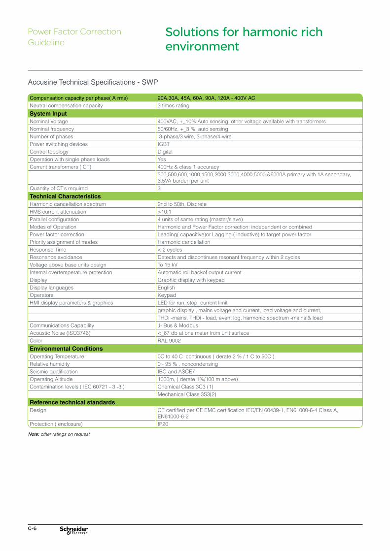
Compensation capacity per phase( A rms) 20A,30A, 45A, 60A, 90A, 120A - 400V AC
Neutral compensation capacity 3 times rating
System InputNominal Voltage 400VAC, +_10% Auto sensing: other voltage available with transformers Nominal frequency 50/60Hz, +_3 % auto sensingNumber of phases 3-phase/3 wire, 3-phase/4-wirePower switching devices IGBTControl topology DigitalOperation with single phase loads YesCurrent transformers ( CT) 400Hz & class 1 accuracy
300,500,600,1000,1500,2000,3000,4000,5000 &6000A primary with 1A secondary, 3.5VA burden per unit
Quantity�of�CT’s�required� 3
Technical CharacteristicsHarmonic cancellation spectrum 2nd to 50th, DiscreteRMS current attenuation >10:1Parallel configuration 4 units of same rating (master/slave)Modes of Operation Harmonic and Power Factor correction: independent or combinedPower factor correction Leading( capacitive)or Lagging ( inductive) to target power factorPriority assignment of modes Harmonic cancellationResponse Time <�2�cyclesResonance avoidance Detects and discontinues resonant frequency within 2 cyclesVoltage above base units design To 15 kVIntemal overtemperature protection Automatic roll backof output currentDisplay Graphic display with keypadDisplay languages EnglishOperators KeypadHMI display parameters & graphics LED for run, stop, current limit
graphic display , mains voltage and current, load voltage and current,THDi -mains, THDi - load, event log, harmonic spectrum -mains & load
Communications Capability J- Bus & ModbusAcoustic Noise (ISO3746) <_67�db�at�one�meter�from�unit�surfaceColor RAL 9002
Environmental ConditionsOperating Temperature 0C to 40 C continuous ( derate 2 % / 1 C to 50C )Relative humidity 0 - 95 % , noncondensingSeismic qualification IBC and ASCE7Operating Altitude 1000m, ( derate 1%/100 m above)Contamination levels ( IEC 60721 - 3 -3 ) Chemical Class 3C3 (1)
Mechanical Class 3S3(2)
Reference technical standardsDesign CE certified per CE EMC certification IEC/EN 60439-1, EN61000-6-4 Class A,
EN61000-6-2Protection ( enclosure) IP20
Accusine Technical Specifications - SWP
Solutions for harmonic rich environment
Power Factor Correction Guideline
Note: other ratings on request

C-7
Solutions by Accusine Model Accusine Model Neutral Harmonics Harmonic
MitigationDPF Correction Load Balancing Var Support
Accusine SWP √ √ √
Accusine PCS √ √ √ √Accusine PFV √ √ √
AccuSine SWP•� Three�or�four�wire�connections�(3�phase�
or 3-phase + Neutral).
•� Up�tp�480�V�supply;�other�possible�with�transformers.
•� Units�from�20�A�to�120�A,�parallel�to 480 A.
•� Cancellation�to�the�50th�order.
•� Neutral�harmonic�correction�at�3�times�unit rating.
•� Displacement�PF�correction�to�set�point.
•� Modbus�&�J-bus�communications.
AccuSine PCS•� Three�wire�connection.
•� From�208�V�to�690�V�supply�(higher�voltages with transformers).
•� Units�from�33�A�to�300�A,�parallel�up�to�99 units.
•� Cancellation�to�50th�harmonic.
•� Displacement�PF�correction�to�set�point.
•� Load�balancing�of�input�current.
•� Rapid�VAR�injection�in�<�1�cycle.
•� Modbus�TCP/IP�and�Ethernet�IP�communications.
•� Can�be�used�with�PF�capacitors�as�Hybrid VAR Compensation (HVC) system.
AccuSine PFV•� Three�wire�connection.
•� From�208�V�to�690�V�supply�(higher�voltages with transformers).
•� Units�from�33�A�to�300�A,�parallel�up�to�99 units.
•� Displacement�PF�correction�to�set�point.
•� Load�balancing�of�input�current.
•� Rapid�VAR�injection�in�<1�cycle.
•� Modbus�TCP/IP�and�Ethernet�IP�communications.
•� Can�be�used�with�PF�capacitors�as�Hybrid VAR Compensation (HVC) system.
Active Filter - AccuSine SWP (Single Unit)AMPS Reference Description 20 PCS020Y4IP20U AccuSine SWP 20A 400V 50-60Hz IP20 Unitary30 PCS030Y4IP20U AccuSine SWP 30A 400V 50-60Hz IP20 Unitary45 PCS045Y4IP20U AccuSine SWP 45A 400V 50-60Hz IP20Unitary60 PCS060Y4IP20U AccuSine SWP 60A 400V 50-60Hz IP20Unitary90 PCS090Y4IP20U AccuSine SWP 90A 400V 50-60Hz IP20 Unitary120 PCS120Y4IP20U AccuSine SWP 120A 400V 50-60Hz IP20 Unitary
Active Filter -- AccuSine SWP ( Parallel Unit application )20 PCS020Y4IP20P AccuSine SWP 20A 400V 50-60Hz IP20 Parallel30 PCS030Y4IP20P AccuSine SWP 30A 400V 50-60Hz IP20 Parallel45 PCS045Y4IP20P AccuSine SWP 45A 400V 50-60Hz IP20 Parallel60 PCS060Y4IP20P AccuSine SWP 60A 400V 50-60Hz IP20 Parallel90 PCS090Y4IP20P AccuSine SWP 90A 400V 50-60Hz IP20 Parallel120 PCS120Y4IP20P AccuSine SWP 120A 400V 50-60Hz IP20 Parallel
Power Factor Correction Guideline
Solutions for harmonic rich environment

C-8

D-1
Capacitor Selection Criteria
LV - Power Quality Products & Solutions
Capacitor Selection Criteria D-2
Life Expectancy of Power Capacitors D-4
Capacitor Selection Criteria D-5

D-2
As various types of capacitors are manufactured therefore capacitor selection becomes a very tough decision for both the marketing personnel and end user. Capacitor selection methodology has been formulated by different capacitor manufacturers based upon following criteria.• % Non-linear load connected• Existing Harmonic THD(V) and THD (I) levels• Number of switching of capacitors• Detuned filter applications• Environmental factors
Life expectancy • Capacitor Rated Voltage• Permissible Over voltage• Maximum permissible current• Maximum ambient temperature• Number of switching operations
No single criterion is fool proof and we have to use several of the above factors to arrive at the appropriate type of capacitor suitable for a given application.
Let us analyse each one of the above factors in detail and understand its limitations.
% Non-linear load connectedThis is the common practices to arrive at the capacitor duty based on the type of application.• If the % non-linear load as compared to transformer capacity is below
10% it is recommended to use Standard duty capacitors.• If % non-linear loads up to 20% it is recommended to use Heavy duty
capacitors. • If % non-linear loads up to 20% it is recommended to use APP-
capacitors.• If % non-linear loads up to 25% it is recommended to use Energy
capacitors.• If % non-linear loads between 25% to 50% it is recommended to use
Reactor + Capacitor (Detuned Filters)• If % non-linear loads above 50% it is recommended to use active filter
solution for this a harmonic study is usually recommended in arriving at the most appropriate solution
Capacitor selection criteriaPower Factor Correction Guideline
D-3
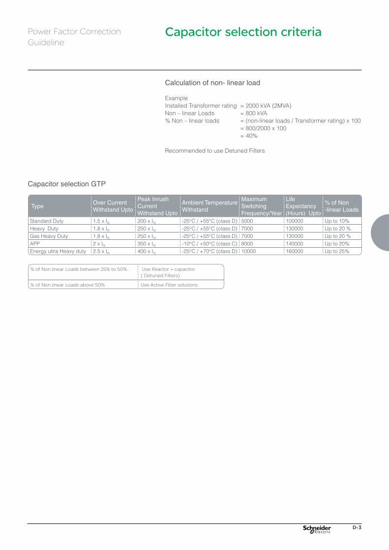
Calculation of non- linear load
ExampleInstalled Transformer rating = 2000 kVA (2MVA)Non�–�linear�Loads� =�800�kVA%�Non�–�linear�loads� =�(non-linear�loads�/�Transformer�rating)�x�100 = 800/2000 x 100 = 40%
Recommended to use Detuned Filters
Capacitor selection criteria
Capacitor selection GTP
TypeOver Current Withstand Upto
Peak Inrush Current Withstand Upto
Ambient Temperature Withstand
Maximum Switching Frequency/Year
Life Expectancy (Hours) Upto
% of Non -linear Loads
Standard Duty 1.5 x IN 200 x IN -25°C / +55°C (class D) 5000 100000 Up to 10%Heavy Duty 1.8 x IN 250 x IN -25°C / +55°C (class D) 7000 130000 Up to 20 %Gas Heavy Duty 1.8 x IN 250 x IN -25°C / +55°C (class D) 7000 130000 Up to 20 %APP 2 x IN 350 x IN -10°C / +50°C (class C) 8000 140000 Up to 20%Energy ultra Heavy duty 2.5 x IN 400 x IN -25°C / +70°C (class D) 10000 160000 Up to 25%
% of Non linear Loads between 25% to 50% Use Reactor + capacitor ( Detuned Filters)
% of Non linear Loads above 50% Use Active Filter solutions
Power Factor Correction Guideline

D-4
Life expectancy of power capacitorsIt is determined by several operating parameters. A few critical operating parameters are:• Type and duration of overload (ex overcurrent, overvoltage)• Maximum voltage level (including short duration overvoltages &
overvoltages due to low load conditions)• Active enclosure temperature and its increase due to increased
ambient temperatures and high RMS capacitor currents (for Ex due to harmonics) If the above operating conditions are as per rated values, rated capacitor life can be expected. Similarly, a shorter capacitor life is obtained if the operating conditions are higher than the rated values.
Change in capacitor life with respect to overvoltage factor (at constant temperature)
Change in capacitor life with respect to average ambient temperature (at constant voltage)
Life expectancy of power capacitors
Power Factor Correction Guideline

D-5
Life Expectancy of Power Capacitors
Rated voltage (Vn)The Rated voltage of the capacitor shall be equal to (or) higher than the maximum network voltage with the power factor correction installation.
The�preferred�rated�voltage�of�the�unit�or�bank�shall�be�240V�for�single�–phase�and�440V�for�the�three�–�phase�system.
Maximum permissible over voltage at Rated frequency (50Hz): 1.00 x Un - Continuous 1.10 x Un - up to 12 hrs per day 1.15 x Un - up to 30 min per day 1.20 x Un - 5 min 1.30 x Un - 1 min
Maximum permissible current (IN)Capacitor units shall be suitable for continuous operation at an rms current 1.30 times the current that occurs at rated sinusoidal voltage and rated frequency, excluding transients. Taking in to account the capacitance tolerances of 1.1CN, the maximum permissible current can be up to 1.43 IN. These over current factors are intended to take care of the combined effects of harmonics and over voltage up to and including 1.10 UN.
Maximum ambient temperature limit
Reference chart for temperature categories.Note: Ambient�air�temperatures�can�be�increased�by�5°C�for�indoor�installations�in enclosuresPlease�see�‘Capacitor�Life�–�Important�Considerations’�below�as�per�the�diagram indicated
Temperature Category
Maximum Ambient Air Temperature (°C)
Upper LimitHighest Mean TemperatureFor One Day For One Year
A 40° 30° 20°B 45° 35° 25°C 50° 40° 30°D 55° 45° 35°
Variation In capacitance due to temperature variationa. At Lower Temp. Limit: y 1%b. At Upper Temp. Limit: y 1%
Change in capacitance with respect to Ambient temperature
Change of Tan Delta (Loss Angle) with respect to Ambient temperature
Power Factor Correction Guideline
Capacitor selection criteria

D-6
Capacitor selection criteria
Life expectancy of power capacitors
Number of switching operationsThe frequent switching on and off of capacitors places additional electrical stress on them due to the inrush current phenomena associated with capacitors. The inrush current magnitude depends upon the kVAr switched and the fault level at the point of capacitor switching. If the capacitors are switched very close to the secondary of the Transformer, then the inrush current is likely to be high as the fault level is high.
Every capacitor type has a peak inrush current rating expressed as multiples of rated current such as 150 IN to 400 IN depending upon capacitor duty.
A capacitor used in APFC application is subjected to frequent switching and hence should be selected to withstand high number of switching operations and capable of withstanding large inrush currents. The reliability of the capacitors used in APFC is proportional to the inrush current rating.
Following any one of techniques are used to reduce the inrush current drawn by capacitors thereby increasing the life of capacitors and associated switching devices.1. Inrush current limiting coils in series with capacitors2. Capacitor duty contactors3. Thyristor switching devices
Environmental factors1. Capacitors are to be installed in dry & away from heat generating
sources. It should be installed, ensuring cross ventilation for better heat conduction
2. For APFC panel application it is recommended to provided forced cooling fan.
3. Additional cooling provision should be made in APFC panels installed with reactors.
Power Factor Correction Guideline

E-1
LV - Power Quality Products & Solutions
Selection of Capacitor (kVAr & Voltage) for Detuned E-2 Filter Application
Selection of Capacitor (kVAr & voltage) for Detuned Filter Application

E-2
In the Detuned filter application the voltage across the capacitors is higher than the nominal system voltage. And also the presence of series reactor will increase the voltage across the capacitor due to Ferranti effect. Therefore capacitors have been designed to withstand higher voltages.
The table provides the details of capacitor voltage applicable for different voltages
Selection of capacitor (kVAr & voltage) for detuned filter application
Calculation for capacitor voltage & output in detuned filter application
Case – 1:Assume a bus with a voltage of 440V, on which there is a 3ph capacitor of 25kVAr, 440V as shown below
The capacitor will draw a current as per the following formula:Ic� =�kVAr�x�1000�/�[VL-L��(√3)]� =�25�x�1000�/�(√3�x�440) = 32.8 Amps.
The capacitive reactance of the capacitor Xc = V2 / (kVAr x 1000) Xc = 7.744 ohms / phase.
440V Bus
25kVAr, 440V Cap. Xc = 7.744Ohms/ph, Ic = 32.8A
Tuning Factor P(%)
Detuning Frequency @50Hz
Tuning order (Fh/F1)
Network Voltage/ Reactor Voltage(Vs)
Capacitor Rated Voltage (Vn)
5.67% 210 Hz 4.2 440V 480V7% 189 Hz 3.8 440V 480V14% 134 H 2.67 440V 525V
Tuning Factor P(%)
Detuning Frequency @50Hz
Tuning order (Fh/F1)
Network Volt-age/ Reactor Voltage(Vs)
Capacitor Rated Voltage (Vn)
5.67% 210 Hz 4.2 440V 525V7% 189 Hz 3.8 440V 525V
440V Bus
7% rector.Xl = 0.5428Ohms/ph
25kVAr, Cap. Xc = 7.744Ohms/ph
Case – 2:Assume, we connect a Series reactor whose Inductive reactance is 7% of above capacitive reactance (i.e. 7% de-tuned reactor):
The effective reactance of the series L-C circuit will be;X = +jXL- jXc� =�+j0.5428�–�j7.744X = -j7.2Ohms / phase.
The current in the series LC circuit will be:Ic1 = VL-L / (√3 x X)Ic1 = 440 / (√3 x7.2)Ic1 = 35.27 Amps.
Option 1
Option 2
Power Factor Correction Guideline
E-3
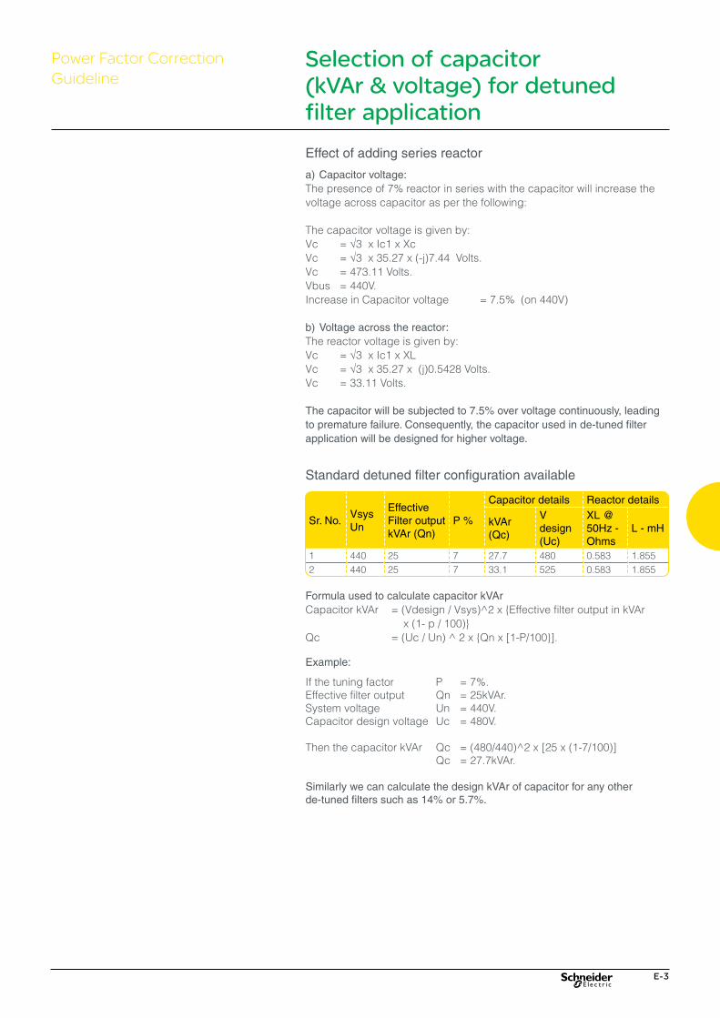
Effect of adding series reactor
a) Capacitor voltage:The presence of 7% reactor in series with the capacitor will increase the voltage across capacitor as per the following:
The capacitor voltage is given by:Vc = √3 x Ic1 x XcVc = √3 x 35.27 x (-j)7.44 Volts.Vc = 473.11 Volts.Vbus = 440V.Increase in Capacitor voltage = 7.5% (on 440V)
b) Voltage across the reactor:The reactor voltage is given by:Vc = √3 x Ic1 x XLVc = √3 x 35.27 x (j)0.5428 Volts.Vc = 33.11 Volts.
The capacitor will be subjected to 7.5% over voltage continuously, leading to premature failure. Consequently, the capacitor used in de-tuned filter application will be designed for higher voltage.
Formula used to calculate capacitor kVArCapacitor kVAr = (Vdesign / Vsys)^2 x {Effective filter output in kVAr x (1- p / 100)}Qc� =�(Uc�/�Un)�^�2�x�{Qn�x�[1-P/100}].
Selection of capacitor (kVAr & voltage) for detuned filter application
Example:
If the tuning factor P = 7%.Effective filter output Qn = 25kVAr.System voltage Un = 440V.Capacitor design voltage Uc = 480V.
Then�the�capacitor�kVAr� Qc� =�(480/440)^2�x�[25�x�(1-7/100)] Qc = 27.7kVAr.
Similarly we can calculate the design kVAr of capacitor for any other de-tuned filters such as 14% or 5.7%.
Standard detuned filter configuration available
Sr. No.VsysUn
Effective Filter output kVAr (Qn)
P %
Capacitor details Reactor details
kVAr (Qc)
V design (Uc)
XL @ 50Hz - Ohms
L - mH
1 440 25 7 27.7 480 0.583 1.8552 440 25 7 33.1 525 0.583 1.855
Power Factor Correction Guideline

E-4
Power Factor Correction Guideline
Effective kVAr out put of Detuned Filter @440V
Selection of 480V capacitors for 7% / 5.7% detuned Filter for 440V
5 5kVAr 7 % / 5.7 % Reactor + 5.6 kVAr , 480VCapacitor10 10 kVAr 7% / 5.7% Reacor + 11.3 kVAr,480V Capacitor12.5 12.5 kVAr 7% / 5.7% Reactor + 14.4 kVAr, 480V
Capacitor15 15 kVAr 7% / 5.7% Reactor + 17 kVAr, 480VCapacitor20 20 kVAr 7% / 5.7% Reactor + 22.4 kVAr , 480VCapacitor25 25 kVAr 7% / 5.7% Reactor + 28.1 kVAr, 480V Capacitor50 50 kVAr 7% / 5.7% Reactor + 2 x 28.1 kVAr, 480V
Capacitor75 75 kVAr 7% / 5.7% Reactor + 3 x 28.1 kVAr, 480V
Capacitor100 100 kVAr 7% / 5.7% Reactor + 4 x 28.1 kVAr, 480V
Capacitor
Effective kVAr out put of Detuned Filter @440V
Selection of 525V capacitors for 7% / 5.7% detuned Filter for 440V
5 5kVAr 7% / 5.7% Reactor + 6.9 kVAr , 525VCapacitor10 10 kVAr 7% / 5.7% Reacor + 13.8 kVAr,525V Capacitor12.5 12.5 kVAr 7%/ 5.7% Reactor + 17.2 kVAr, 525V
Capacitor15 15 kVAr 7% / 5.7% Reactor + 20.6 kVAr, 525VCapacitor20 20 kVAr 7% / 5.7% Reactor + 27.5 kVAr , 525VCapacitor25 25 kVAr 7% / 5.7% Reactor + 33.1 kVAr, 525V Capacitor50 50 kVAr 7% / 5.7% Reactor + 2 x 33.1 kVAr, 525V
Capacitor75 75 kVAr 7% / 5.7% Reactor + 3 x 33.1 kVAr, 525V
Capacitor100 100 kVAr 7% / 5.7% Reactor + 4 x 33.1 kVAr, 525V
Capacitor
Effective kVAr out put of Detuned Filter @440V
Selection of 525V capacitors for 14% detuned Filter for 440V
5 5kVAr 14% Reactor + 6.9 kVAr, 525VCapacitor10 10 kVAr 14% Reacor + 12.5 kVAr, 525V Capacitor12.5 12.5 kVAr 14% Reactor + 15.4 kVAr, 525V Capacitor15 15 kVAr 14% Reactor + 18.5 kVAr, 525VCapacitor20 20 kVAr 14% Reactor + 25 kVAr, 525VCapacitor25 25 kVAr 14% Reactor + 30.6 kVAr, 525V Capacitor50 50 kVAr 14% Reactor + 2 x 30.6 kVAr, 525V Capacitor75 75 kVAr 14% Reactor + 3 x 30.6 kVAr, 525V Capacitor100 100 kVAr 14% Reactor + 4 x 30.6 kVAr, 525V Capacitor
Selection of capacitor (kVAr & voltage) for detuned filter application

F-1
Low Voltage Capacitors
LV - Power Quality Products & Solutions
EasyCan (SDuty) F-2
VarplusCan (HDuty) F-4
VarplusCan (GHDuty) F-7
VarplusCan Mechanical Characteristics F-10
VarplusBox Standard Duty F-12
VarplusBox Heavy Duty F-14
VarplusBox Energy, Ultra Heavy Duty(MD-XL) F-17
VarplusBox Mechanical Characteristics F-20
New
New
New
F-2
EasyCan (SDuty)Low Voltage Capacitors
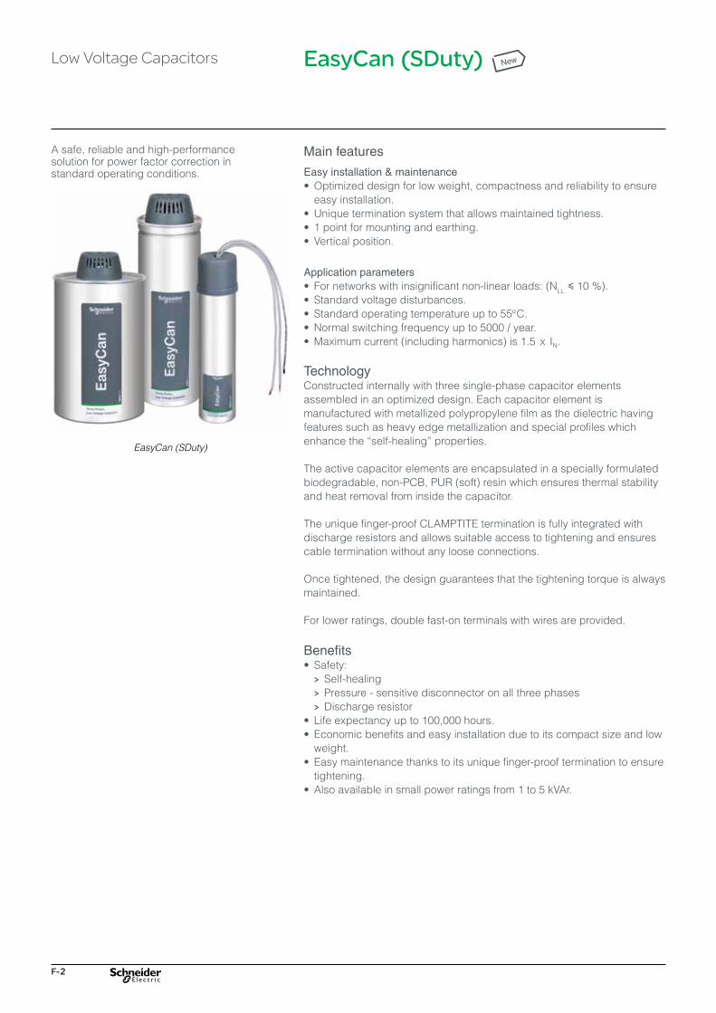
A safe, reliable and high-performance solution for power factor correction in standard operating conditions.
EasyCan (SDuty)
Main features
Easy installation & maintenance•�Optimized design for low weight, compactness and reliability to ensure
easy installation.•�Unique termination system that allows maintained tightness.•� 1 point for mounting and earthing.•�Vertical position.
Application parameters •� For networks with insignificant non-linear loads: (NLL y 10 %).•�Standard voltage disturbances.•�Standard operating temperature up to 55°C.•�Normal switching frequency up to 5000 / year.•�Maximum current (including harmonics) is 1.5 x IN.
TechnologyConstructed internally with three single-phase capacitor elements assembled in an optimized design. Each capacitor element is manufactured with metallized polypropylene film as the dielectric having features such as heavy edge metallization and special profiles which enhance�the�“self-healing”�properties.
The active capacitor elements are encapsulated in a specially formulated biodegradable, non-PCB, PUR (soft) resin which ensures thermal stability and heat removal from inside the capacitor.
The unique finger-proof CLAMPTITE termination is fully integrated with discharge resistors and allows suitable access to tightening and ensures cable termination without any loose connections.
Once tightened, the design guarantees that the tightening torque is always maintained.
For lower ratings, double fast-on terminals with wires are provided.
Benefits•� Safety: > Self-healing > Pressure - sensitive disconnector on all three phases > Discharge resistor•��Life�expectancy�up�to�100,000�hours.•��Economic�benefits�and�easy�installation�due�to�its�compact�size�and�low�
weight.•��Easy�maintenance�thanks�to�its�unique�finger-proof�termination�to�ensure�
tightening.•��Also�available�in�small�power�ratings�from�1�to�5�kVAr.
New
F-3
Low Voltage Capacitors
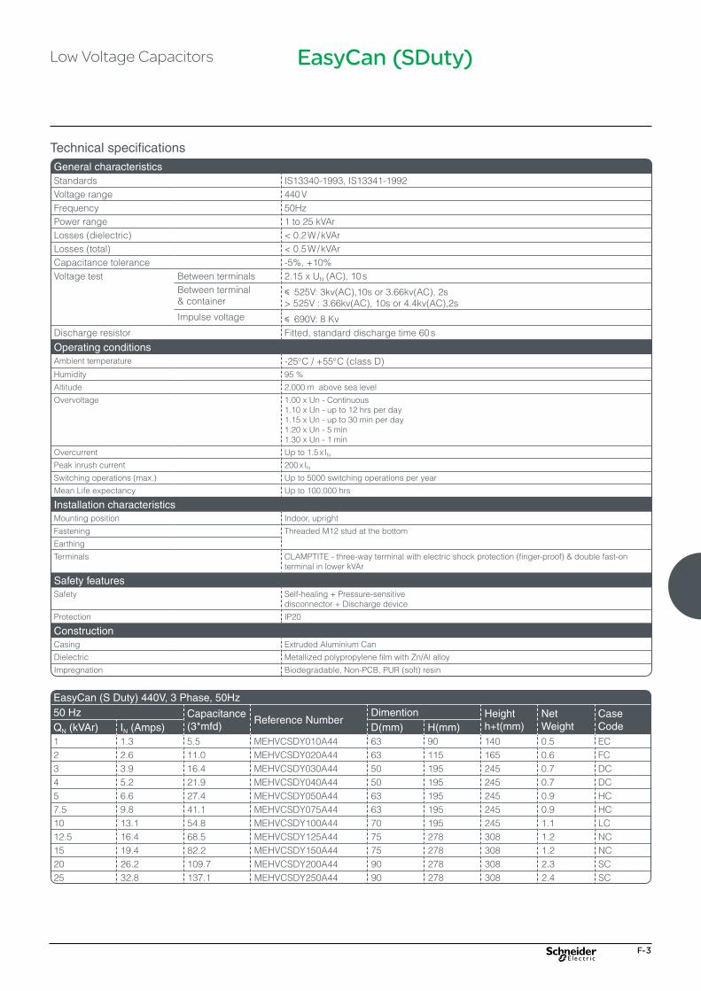
Technical specificationsGeneral characteristics Standards IS13340-1993, IS13341-1992Voltage range 440 VFrequency 50HzPower range 1 to 25 kVAr Losses (dielectric) <�0.2�W�/�kVArLosses (total) <�0.5�W�/�kVArCapacitance tolerance -5%, +10%Voltage test Between terminals 2.15 x UN (AC), 10 s
Between terminal & container
y 525V: 3kv(AC),10s or 3.66kv(AC), 2s>�525V�:�3.66kv(AC),�10s�or�4.4kv(AC),2s
Impulse voltage y 690V: 8 KvDischarge resistor Fitted, standard discharge time 60 s
Operating conditionsAmbient temperature -25°C / +55°C (class D)Humidity 95 %
Altitude 2,000 m above sea level
Overvoltage 1.00 x Un - Continuous 1.10 x Un - up to 12 hrs per day1.15 x Un - up to 30 min per day 1.20 x Un - 5 min1.30 x Un - 1 min
Overcurrent Up to 1.5 x IN
Peak inrush current 200 x IN
Switching operations (max.) Up to 5000 switching operations per year
Mean Life expectancy Up to 100,000 hrs
Installation characteristicsMounting position Indoor, upright
Fastening Threaded M12 stud at the bottom
Earthing
Terminals CLAMPTITE - three-way terminal with electric shock protection (finger-proof) & double fast-on terminal in lower kVAr
Safety featuresSafety Self-healing + Pressure-sensitive
disconnector + Discharge device
Protection IP20
ConstructionCasing Extruded Aluminium Can
Dielectric Metallized polypropylene film with Zn/Al alloy
Impregnation Biodegradable, Non-PCB, PUR (soft) resin
EasyCan (S Duty) 440V, 3 Phase, 50Hz50 Hz Capacitance
(3*mfd)Reference Number
Dimention Height h+t(mm)
Net Weight
Case CodeQN (kVAr) IN (Amps) D(mm) H(mm)
1 1.3 5.5 MEHVCSDY010A44 63 90 140 0.5 EC2 2.6 11.0 MEHVCSDY020A44 63 115 165 0.6 FC3 3.9 16.4 MEHVCSDY030A44 50 195 245 0.7 DC4 5.2 21.9 MEHVCSDY040A44 50 195 245 0.7 DC5 6.6 27.4 MEHVCSDY050A44 63 195 245 0.9 HC7.5 9.8 41.1 MEHVCSDY075A44 63 195 245 0.9 HC10 13.1 54.8 MEHVCSDY100A44 70 195 245 1.1 LC12.5 16.4 68.5 MEHVCSDY125A44 75 278 308 1.2 NC15 19.4 82.2 MEHVCSDY150A44 75 278 308 1.2 NC20 26.2 109.7 MEHVCSDY200A44 90 278 308 2.3 SC25 32.8 137.1 MEHVCSDY250A44 90 278 308 2.4 SC
EasyCan (SDuty)

F-4
VarplusCan (HDuty)
A safe, reliable and high-performance solution for power factor correction in heavy-duty operating conditions.
VarplusCan HDuty
Main features
Easy installation & maintenance•�Optimized�design�for�low�weight,�compactness�and�reliability�to�ensure�
easy installation.•� Unique�termination�system�that�allows�maintained�tightness.•� 1�point�for�mounting�and�earthing.•� Vertical�and�horizontal�position.�
Application parameters •� For�networks�with�insignificant�non-linear�loads:�(NLL�<�20�%).•� Significant�voltage�disturbances.•� Standard�operating�temperature�up�to�55°C.•� Normal�switching�frequency�up�to�7000�/year.•�Maximum�current�(including�harmonics)�is�1.8�x�IN.
TechnologyConstructed internally with three single-phase capacitor elements. Each capacitor element is manufactured with metallized polypropylene film as the dielectric, having features such as heavy edge, slope metallization and wave-cut profile to ensure increased current handling capacity and reduced temperature rise.
The active capacitor elements are coated with specially formulated sticky resin which ensures high overload capabilities and good thermal and mechanical properties
The unique finger-proof CLAMPTITE termination is fully integrated with discharge resistors, allowing suitable access for tightening and ensuring cable termination without any loose connections.
For lower ratings, double fast-on terminals with wires are provided.
Benefits•� Total�safety: > Self - healing > Pressure- sensitive disconnector > Discharge resistor•� Long�life�expectancy�(up�to�130,000�hours).•� Installation�in�any�position�vertical�or�horizontal•�Optimized�geometric�design�for�improved�thermal�performance.•� Special�resistivity�and�metallisation�profile�will�enhance�life�
and will give higher thermal efficiency with lower temperature rise.•��Unique�finger-proof�termination�that�ensures�tightening�for�CLAMPITE�
terminals.
Terminal Unique FeaturesCLAMPITE (IP20): Three phase terminal with electric shock protection (finger proof) up to 30kVAr unit•� Termination�is�designed�for�cable�entry�of�cross�section�minimum�2.5�sq�
mm, maximum 16 sq mm•� This�unique�clamptite�design�enables�the�use�of�cables�without�lugs.�
Which ensures better termination and avoids loose connection.•�STUD type (IP00): Three phase terminal provided for better current
handling capablities (for 40kVAr & 50kVAr units, 440V)•� Termination�is�designed�for�cable�entry�of�cross�section�35�sq�mm�for�
higher kVAr ratings
Low Voltage Capacitors New
50 kVAr unit, 440V

F-5
Technical specificationsGeneral characteristics Standards IS3340 - 1993, IS13341 - 1992, IEC 60831-1/-2Voltage range 440V, 480V, 525VFrequency 50HzPower range 1 to 50 kVAr Losses (dielectric) <�0.2�W�/�kVArLosses (total) <�0.5�W�/�kVArCapacitance tolerance -5%, +10%Voltage test Between terminals 2.15 x UN (AC), 10 s
Between terminal & container
y 525 V: 3 kV (AC), 10 s or 3.66 kV (AC), 2 s>�525�V:�3.66�kV�(AC),�10�s�or�4.4�kV�(AC),�2�s
Impulse voltage y 690 V: 8 kVDischarge resistor Fitted, standard discharge time 60 sAmbient temperature -25°C / +55°C (Class D)Humidity 95 %Altitude 2,000 m above sea levelOvervoltage 1.00 x Un - Continuous
1.10 x Un - up to 12 hrs per day1.15 x Un - up to 30 min per day 1.20 x Un - 5 min1.30 x Un - 1 min
Overcurrent Up to 1.8 x IN Peak inrush current 250 x IN
Switching operations (max.) Up to 7000 switching operations per yearMean Life expectancy Up to 130,000 hrs
Installation characteristicsMounting position Indoor, upright & horizontalFastening Threaded M12 stud at the bottomEarthingTerminals CLAMPTITE - three-way terminal with electric shock protection (finger-proof) & double
fast-on terminal in lower kVAr
Safety featuresSafety Self-healing + Pressure-sensitive disconnector + Discharge deviceProtection IP20
ConstructionCasing Extruded Aluminium CanDielectric Metallized polypropylene film with Zn/Al alloy.
Special resistivity & profile, special edge (wave-cut)Impregnation Non-PCB, PUR sticky resin (Dry)
Low Voltage Capacitors VarplusCan (HDuty)
F-6
VarplusCan (HDuty)
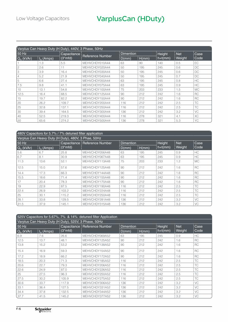
Varplus Can Heavy Duty (H Duty), 440V, 3 Phase, 50Hz50 Hz Capacitance
(3*mfd)Reference Number
Dimention Height h+t(mm)
Net Weight
Case CodeQN (kVAr) IN (Amps) D(mm) H(mm)
1 1.3 5.5 MEHVCHDY010A44 63 90 140 0.5 EC2 2.6 11 MEHVCHDY020A44 50 195 245 0.6 DC3 3.9 16.4 MEHVCHDY030A44 50 195 245 0.6 DC4 5.2 21.9 MEHVCHDY040A44 50 195 245 0.7 DC5 6.6 27.4 MEHVCHDY050A44 63 195 245 0.8 HC7.5 9.8 41.1 MEHVCHDY075A44 63 195 245 0.9 HC10 13.1 54.8 MEHVCHDY100A44 75 203 233 1.5 MC12.5 16.4 68.5 MEHVCHDY125A44 90 212 242 1.6 RC15 19.7 82.2 MEHVCHDY150A44 90 212 242 1.6 RC20 26.2 109.7 MEHVCHDY200A44 116 212 242 2.5 TC25 32.8 137.1 MEHVCHDY250A44 116 212 242 2.5 TC30 39.4 164.5 MEHVCHDY300A44 136 212 242 3.2 VC40 52.5 219.3 MEHVCHDY400A44 116 278 321 4.1 XC50 65.6 274.2 MEHVCHDY500A44 136 278 321 5.3 YC
480V Capacitors for 5.7% / 7% detuned filter applicationVarplus Can Heavy Duty (H Duty), 480V, 3 Phae, 50Hz50 Hz Capacitance
(3*mfd)Reference Number Dimention Height
h+t(mm)Net Weight
Case CodeQN (kVAr) IN (Amps) D(mm) H(mm)
5.6 6.7 25.8 MEHVCHDY056A48 63 195 245 0.9 HC6.7 8.1 30.9 MEHVCHDY067A48 63 195 245 0.9 HC11.3 13.6 52.1 MEHVCHDY113A48 75 203 233 1.2 MC
12.5 15.0 57.6 MEHVCHDY125A48 90 212 242 1.6 RC
14.4 17.3 66.3 MEHVCHDY144A48 90 212 242 1.6 RC15.5 18.6 71.4 MEHVCHDY155A48 90 212 242 1.6 RC17 20.4 78.3 MEHVCHDY170A48 90 212 242 1.6 RC19 22.9 87.5 MEHVCHDY190A48 116 212 242 2.5 TC22.4 26.9 103.2 MEHVCHDY224A48 116 212 242 2.5 TC25 30.1 115.2 MEHVCHDY250A48 116 212 242 2.5 TC28.1 33.8 129.5 MEHVCHDY281A48 136 212 242 3.2 VC31.5 37.9 145.1 MEHVCHDY315A48 136 212 242 3.2 VC
525V Capacitors for 5.67%, 7% & 14% detuned filter ApplicationVarplus Can Heavy Duty (H Duty), 525V, 3 Phase, 50Hz50 Hz Capacitance
(3*mfd)Reference Number Dimention Height
h+t(mm)Net Weight
Case CodeQN (kVAr) IN (Amps) D(mm) H(mm)
6.9 7.6 26.6 MEHVCHDY069A52 63 195 245 0.9 HC12.5 13.7 48.1 MEHVCHDY125A52 90 212 242 1.6 RC13.8 15.2 53.2 MEHVCHDY138A52 90 212 242 1.6 RC
15.4 16.9 59.3 MEHVCHDY154A52 90 212 242 1.6 RC
17.2 18.9 66.2 MEHVCHDY172A52 90 212 242 1.6 RC18.5 20.3 71.3 MEHVCHDY185A52 116 212 242 2.5 TC20.6 22.7 79.3 MEHVCHDY206A52 116 212 242 2.5 TC22.6 24.9 87.0 MEHVCHDY226A52 116 212 242 2.5 TC25 27.5 96.3 MEHVCHDY250A52 116 212 242 2.5 TC27.5 30.2 105.9 MEHVCHDY275A52 116 212 242 2.5 TC30.6 33.7 117.9 MEHVCHDY306A52 136 212 242 3.2 VC33.1 36.4 127.5 MEHVCHDY331A52 136 212 242 3.2 VC34.4 37.8 132.5 MEHVCHDY344A52 136 212 242 3.2 VC37.7 41.5 145.2 MEHVCHDY377A52 136 212 242 3.2 VC
Low Voltage Capacitors
F-7
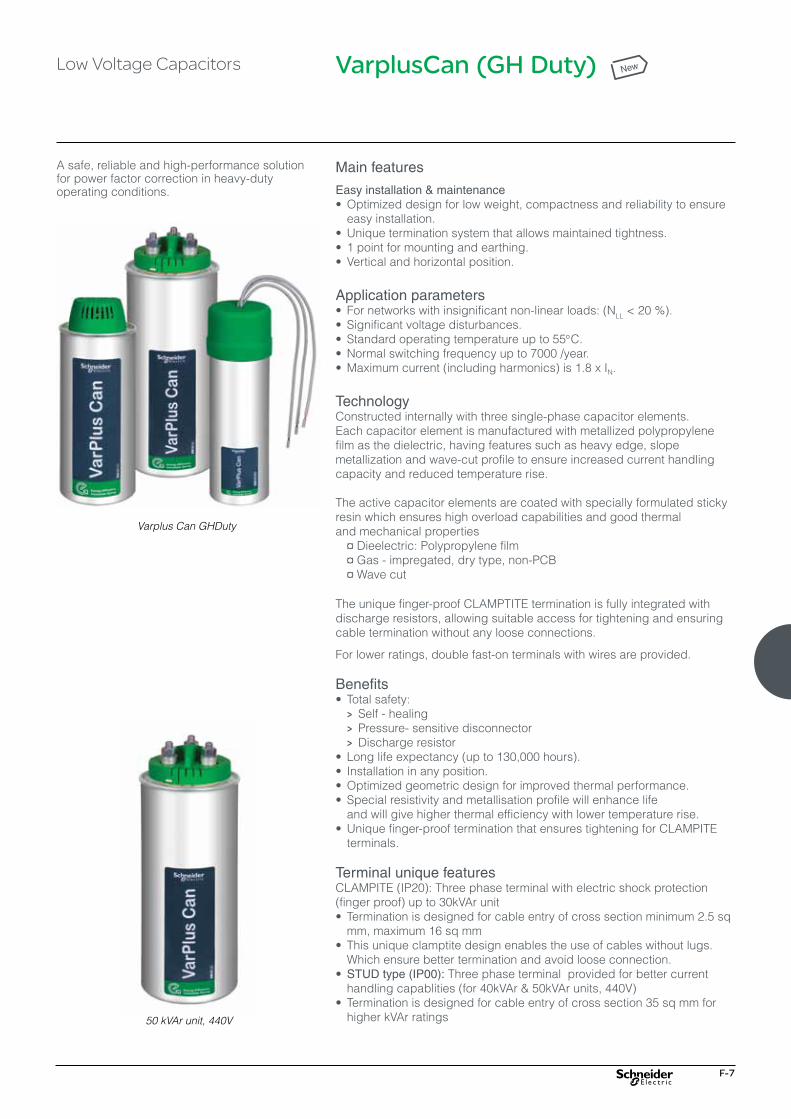
VarplusCan (GH Duty)
A safe, reliable and high-performance solution for power factor correction in heavy-duty operating conditions.
Main features
Easy installation & maintenance•�Optimized�design�for�low�weight,�compactness�and�reliability�to�ensure�
easy installation.•� Unique�termination�system�that�allows�maintained�tightness.•� 1�point�for�mounting�and�earthing.•� Vertical�and�horizontal�position.�
Application parameters •� For�networks�with�insignificant�non-linear�loads:�(NLL�<�20�%).•� Significant�voltage�disturbances.•� Standard�operating�temperature�up�to�55°C.•� Normal�switching�frequency�up�to�7000�/year.•�Maximum�current�(including�harmonics)�is�1.8�x�IN.
TechnologyConstructed internally with three single-phase capacitor elements. Each capacitor element is manufactured with metallized polypropylene film as the dielectric, having features such as heavy edge, slope metallization and wave-cut profile to ensure increased current handling capacity and reduced temperature rise.
The active capacitor elements are coated with specially formulated sticky resin which ensures high overload capabilities and good thermal and mechanical properties � ¤�Dieelectric:�Polypropylene�film� ¤�Gas�-�impregated,�dry�type,�non-PCB� ¤�Wave�cut
The unique finger-proof CLAMPTITE termination is fully integrated with discharge resistors, allowing suitable access for tightening and ensuring cable termination without any loose connections.
For lower ratings, double fast-on terminals with wires are provided.
Benefits•� Total�safety: > Self - healing > Pressure- sensitive disconnector > Discharge resistor•� Long�life�expectancy�(up�to�130,000�hours).•� Installation�in�any�position.•�Optimized�geometric�design�for�improved�thermal�performance.•� Special�resistivity�and�metallisation�profile�will�enhance�life�
and will give higher thermal efficiency with lower temperature rise.•� Unique�finger-proof�termination�that�ensures�tightening�for�CLAMPITE�
terminals.
Terminal unique featuresCLAMPITE (IP20): Three phase terminal with electric shock protection (finger proof) up to 30kVAr unit•� Termination�is�designed�for�cable�entry�of�cross�section�minimum�2.5�sq�
mm, maximum 16 sq mm•� This�unique�clamptite�design�enables�the�use�of�cables�without�lugs.�
Which ensure better termination and avoid loose connection.•�STUD type (IP00): Three phase terminal provided for better current
handling capablities (for 40kVAr & 50kVAr units, 440V)•� Termination�is�designed�for�cable�entry�of�cross�section�35�sq�mm�for�
higher kVAr ratings
Low Voltage Capacitors New
Varplus Can GHDuty
50 kVAr unit, 440V

F-8
VarplusCan (GH Duty)
Technical specificationsGeneral characteristics
Standards IS3340 - 1993, IS13341 - 1992, IEC 60831-1/-2Voltage range 440V, 480V, 525VFrequency 50HzPower range 5 kVAr to 50 kVArLosses (dielectric) <�0.2�W�/�kVArLosses (total) <�0.5�W�/�kVArCapacitance tolerance -5%, +10%Voltage test Between terminals 2.15 x UN (AC), 10 s
Between terminal & container
y 525 V: 3 kV (AC), 10 s or 3.66 kV (AC), 2 s>�525�V:�3.66�kV�(AC),�10�s�or�4.4�kV�(AC),�2�s
Impulse voltage y 690 V: 8 kVDischarge resistor Fitted, standard discharge time 60 sAmbient temperature -25°C / +55°C (Class D)Humidity 95%Altitude 2,000 m above sea levelOvervoltage 1.00 x Un - Continuous
1.10 x Un - up to 12 hrs per day1.15 x Un - up to 30 min per day 1.20 x Un - 5 min1.30 x Un - 1 min
Overcurrent Up to 1.8 x IN Peak inrush current 250 x IN
Switching operations (max.) Up to 7000 switching operations per yearMean Life expectancy Up to 130,000 hrs
Installation characteristicsMounting position Indoor, upright & horizontalFastening Earthing
Threaded M12 stud at the bottom
Terminals CLAMPTITE - three-way terminal with electric shock protection (finger-proof) & double fast-on terminal in lower kVAr
Safety featuresSafety Self-healing + Pressure-sensitive disconnector + Discharge deviceProtection IP20
ConstructionCasing Extruded Aluminium CanDielectric Metallized polypropylene film with Zn/Al alloy.
Special resistivity & profile, special edge (wave-cut)Impregnation Gas - impregated, dry type, non-PCB
Low Voltage Capacitors

F-9
VarplusCan (GH Duty)
Varplus Can Gas Heavy Duty (GH Duty) Dry 440V, 3 Phase, 50Hz50 Hz Capacitance
(3*mfd)Reference Number Dimention Height
h+t(mm)Net Weight
Case CodeQN (kVAr) IN (Amps) D(mm) H(mm)
5 6.6 27.4 MEHVCGSF050A44 63 195 245 0.8 HC7.5 9.8 41.1 MEHVCGSF075A44 63 195 245 0.9 HC10 13.1 54.8 MEHVCGSF100A44 75 203 233 0.9 MC12.5 16.4 68.5 MEHVCGSF125A44 90 212 242 1.6 RC15 19.4 82.2 MEHVCGSF150A44 90 212 242 1.6 RC20 26.2 109.7 MEHVCGSF200A44 116 212 242 2.5 TC25 32.8 137.1 MEHVCGSF250A44 116 212 242 2.5 TC30 39.4 164.5 MEHVCGSF300A44 136 212 242 3.2 VC40 52.5 219.3 MEHVCGSF400A44 116 278 321 4.1 XC50 65.6 274.2 MEHVCGSF500A44 136 278 321 5.3 YC
480V Capacitors for 5.7% / 7% Detuned filter applicationVarplus Can Gas Heavy Duty (GH Duty), 480V, 3 Phase, 50Hz50 Hz Capacitance
(3*mfd)Reference Number Dimention Height
h+t(mm)Net Weight
Case CodeQN (kVAr) IN (Amps) D(mm) H(mm)
5.6 6.7 25.8 MEHVCGSF056A48 63 195 245 0.9 HC6.7 8.1 30.9 MEHVCGSF067A48 63 195 245 0.9 HC11.3 13.6 52.1 MEHVCGSF113A48 75 203 233 1.2 MC12.5 15.0 57.6 MEHVCGSF125A48 90 212 242 1.6 RC14.4 17.3 66.3 MEHVCGSF144A48 90 212 242 1.6 RC15.5 18.6 71.4 MEHVCGSF155A48 90 212 242 1.6 RC17 20.4 78.3 MEHVCGSF170A48 90 212 242 1.6 RC19 22.9 87.5 MEHVCGSF190A48 116 212 242 2.5 TC22.4 26.9 103.2 MEHVCGSF224A48 116 212 242 2.5 TC25 30.1 115.2 MEHVCGSF250A48 116 212 242 2.5 TC28.1 33.8 129.5 MEHVCGSF281A48 136 212 242 3.2 VC31.5 37.9 145.1 MEHVCGSF315A48 136 212 242 3.2 VC
525V Capacitors for 5.67%, 7% / 14% Detuned filter applicationVarplus Can Gas Heavy Duty (GH Duty), 525V, 3 Phase, 50Hz50 Hz Capacitance
(3*mfd)Reference Number Dimention Height
h+t(mm)Net Weight
Case CodeQN (kVAr) IN (Amps) D(mm) H(mm)
6.9 7.6 26.6 MEHVCGSF069A52 63 195 245 0.9 HC12.5 13.7 48.1 MEHVCGSF125A52 90 212 242 1.6 RC13.8 15.2 53.2 MEHVCGSF138A52 90 212 242 1.6 RC15.4 16.9 59.3 MEHVCGSF154A52 90 212 242 1.6 RC17.2 18.9 66.2 MEHVCGSF172A52 90 212 242 1.6 RC18.5 20.3 71.3 MEHVCGSF185A52 116 212 242 2.5 TC20.6 22.7 79.3 MEHVCGSF206A52 116 212 242 2.5 TC22.6 24.9 87.0 MEHVCGSF226A52 116 212 242 2.5 TC25 27.5 96.3 MEHVCGSF250A52 116 212 242 2.5 TC27.5 30.2 105.9 MEHVCGSF275A52 116 212 242 2.5 TC30.6 33.7 117.9 MEHVCGSF306A52 136 212 242 3.2 VC33.1 36.4 127.5 MEHVCGSF331A52 136 212 242 3.2 VC34.4 37.8 132.5 MEHVCGSF344A52 136 212 242 3.2 VC37.7 41.5 145.2 MEHVCGSF377A52 136 212 242 3.2 VC
Low Voltage Capacitors

F-10
VarplusCan mechanical characteristics
Case Code: DC,HC,FC,EC & LC
Creepage distance min.16 mmClearance min.16 mmExpansion (a) max.10 mm
Mounting details (for M10/M12 mounting stud)
Torque M10: 7 N.mM12: 10 N.m
Toothed washer M10/M12Hex nut M10/M12Terminal assembly Ht. (t) 50 mm
Size (d) TS TH�50 M10 10 mm�63 M12 13 mm�70 M12 16 mm
Case code
Diameter d (mm)
Height h (mm)
Height h + t (mm)
Weight (kg)
DC 50 195 245 0.7EC 63 90 140 0.5FC 63 115 165 0.5HC 63 195 245 0.9LC 70 195 245 1.1
EasyCan DC, EC, FC, HC & LC.
VarplusCan MC & RC
Case Code: MC & RC
Creepage distance min.13 mmClearance min.13 mmExpansion (a) max.12 mm
Mounting details (for M12 mounting stud)
Torque T = 10 NmToothed washer J12.5 DIN 6797Hex nut BM12 DIN 439Terminal screw M5
Terminal assembly Ht. (t) 33 mm
Case code
Diameter d (mm)
Height h (mm)
Height h + t (mm)
Weight (kg)
MC 75 203 233 1.2RC 90 212 242 1.6
Low Voltage Capacitors

F-11
VarplusCan mechanical characteristics
VarplusCan TC & VC.
Case Code: TC & VC
Creepage distance min.13 mmClearance min.13 mmExpansion (a) max.12 mm
Mounting details (for M12 mounting stud)
Torque T = 10 NmToothed washer J12.5 DIN 6797Hex nut BM12 DIN 439Terminal screw M5Terminal assembly Ht. (t) 33 mm
Case code
Diameter d (mm)
Height h (mm)
Height h + t (mm)
Weight (kg)
TC 116 212 242 2.5VC 136 212 242 3.2
Case Code: XC & YC
Creepage distance min.13 mmClearance 34 mm
Expansion (a) max.17 mm
Mounting details (for M12 mounting stud)
Torque T = 10 NmToothed washer J12.5 DIN 6797Hex nut BM12 DIN 439Terminal screw M10Terminal assembly Ht. (t) 43 mm
Case code
Diameter d (mm)
Height h (mm)
Height h + t (mm)
Weight (kg)
XC 116 278 321 4.1YC 136 278 321 5.3
Low Voltage Capacitors
VarplusCan XC & YC.

F-12
VarplusBox standard duty
A safe, reliable and high-performance solution for power factor correction in standard operating conditions.
VarplusBox SDuty
Main features
Robustness•��Double�metallic�protection.� Mechanically�well�suited�for�“stand-alone”�installations.�
Application parameters •� For�networks�with�insignificant�non-linear�loads�(NLL y 10 %).•� Standard�voltage�disturbances.•� Standard�operating�temperature�up�to�55°C.•� Normal�switching�frequency�up�to�5000�/year.•�Maximum�current�withstand�1.5�x�IN.
TechnologyConstructed internally with three single-phase capacitor elements to form a three phase delta connected capacitor.
The design is specially adapted for mechanical stability. The enclosures of the units are designed to ensure that the capacitors operate reliably in hot and humid tropical conditions, without the need of any additional ventilation or louvres (see technical specifications).
Special attention is paid to equalization of temperatures within the capacitor enclosures since this gives better overall performance.
Benefits •�Mechanically�well�suited�for�“stand-alone”�installations.�•� Safety: > Self - healing > Pressure - sensitive disconnector on all three phases. > Discharge resistor•� These�capacitors�can�be�easily�mounted�inside�panels�or�in�a�stand-
alone configuration. •� Availability�on�power�ratings�up�to�50�kVAr.•� Suitable�for�flexible�banking.
Low Voltage Capacitors
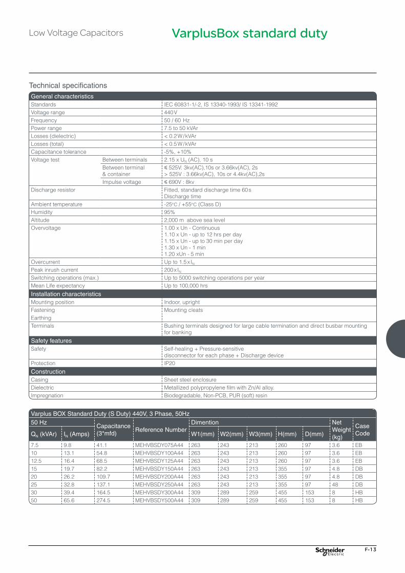
F-13
Technical specifications
VarplusBox standard duty
Peak inrush current 200 x IN
Switching operations (max.) Up to 5000 switching operations per yearMean Life expectancy Up to 100,000 hrs
Installation characteristicsMounting position Indoor, uprightFastening Mounting cleatsEarthingTerminals Bushing terminals designed for large cable termination and direct busbar mounting
for banking
Safety featuresSafety Self-healing + Pressure-sensitive
disconnector for each phase + Discharge deviceProtection IP20
ConstructionCasing Sheet steel enclosureDielectric Metallized polypropylene film with Zn/Al alloy.Impregnation Biodegradable, Non-PCB, PUR (soft) resin
General characteristics Standards IEC 60831-1/-2, IS 13340-1993/ IS 13341-1992Voltage range 440 VFrequency 50 / 60 HzPower range 7.5 to 50 kVAr Losses (dielectric) <�0.2�W�/�kVArLosses (total) <�0.5�W�/�kVArCapacitance tolerance -5%, +10%Voltage test Between terminals 2.15 x UN (AC), 10 s
Between terminal & container
y 525V: 3kv(AC),10s or 3.66kv(AC), 2s>�525V�:�3.66kv(AC),�10s�or�4.4kv(AC),2s
Impulse voltage y 690V : 8kvDischarge resistor Fitted, standard discharge time 60 s
Discharge timeAmbient temperature -25°C / +55°C (Class D)Humidity 95%Altitude 2,000 m above sea levelOvervoltage 1.00 x Un - Continuous
1.10 x Un - up to 12 hrs per day1.15 x Un - up to 30 min per day1.30 x Un - 1 min1.20 xUn - 5 min
Overcurrent Up to 1.5 x IN
Varplus BOX Standard Duty (S Duty) 440V, 3 Phase, 50Hz50 Hz
Capacitance (3*mfd)
Reference Number Dimention Net
Weight (kg)
Case CodeQN (kVAr) IN (Amps) W1(mm) W2(mm) W3(mm) H(mm) D(mm)
7.5 9.8 41.1 MEHVBSDY075A44 263 243 213 260 97 3.6 EB10 13.1 54.8 MEHVBSDY100A44 263 243 213 260 97 3.6 EB12.5 16.4 68.5 MEHVBSDY125A44 263 243 213 260 97 3.6 EB15 19.7 82.2 MEHVBSDY150A44 263 243 213 355 97 4.8 DB20 26.2 109.7 MEHVBSDY200A44 263 243 213 355 97 4.8 DB25 32.8 137.1 MEHVBSDY250A44 263 243 213 355 97 48 DB30 39.4 164.5 MEHVBSDY300A44 309 289 259 455 153 8 HB50 65.6 274.5 MEHVBSDY500A44 309 289 259 455 153 8 HB
Low Voltage Capacitors
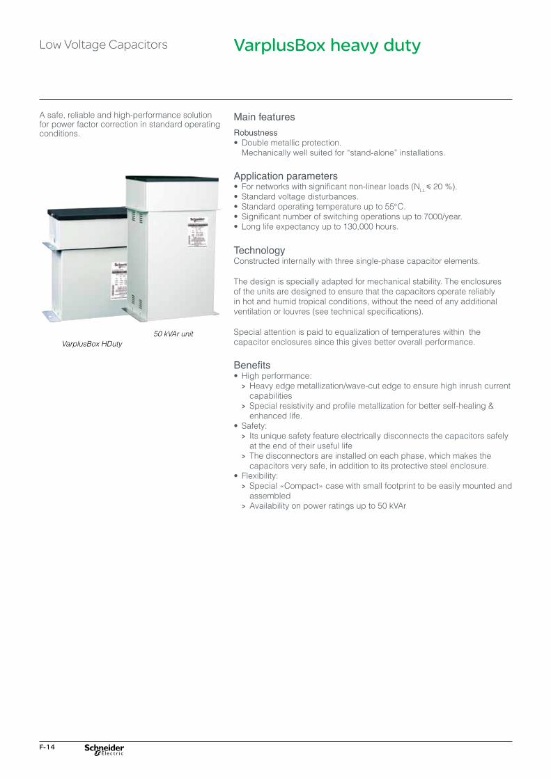
F-14
VarplusBox heavy duty
A safe, reliable and high-performance solution for power factor correction in standard operating conditions.
Main features
Robustness•� Double�metallic�protection.� Mechanically�well�suited�for�“stand-alone”�installations.�
Application parameters •��For�networks�with�significant�non-linear�loads�(NLL y 20 %).•� Standard�voltage�disturbances.•� Standard�operating�temperature�up�to�55°C.•� Significant�number�of�switching�operations�up�to�7000/year.•� Long�life�expectancy�up�to�130,000�hours.
Technology Constructed internally with three single-phase capacitor elements.
The design is specially adapted for mechanical stability. The enclosures of the units are designed to ensure that the capacitors operate reliably in hot and humid tropical conditions, without the need of any additional ventilation or louvres (see technical specifications).
Special attention is paid to equalization of temperatures within the capacitor enclosures since this gives better overall performance.
Benefits •� High�performance: > Heavy edge metallization/wave-cut edge to ensure high inrush current
capabilities > Special resistivity and profile metallization for better self-healing &
enhanced life.•� Safety: > Its unique safety feature electrically disconnects the capacitors safely
at the end of their useful life > The disconnectors are installed on each phase, which makes the
capacitors very safe, in addition to its protective steel enclosure.•� Flexibility: > Special�«Compact»�case�with�small�footprint�to�be�easily�mounted�and�
assembled > Availability on power ratings up to 50 kVAr
VarplusBox HDuty50 kVAr unit
Low Voltage Capacitors

F-15
VarplusBox heavy duty
Technical specifications
Peak inrush current 250 x IN
Switching operations (max.) Up to 7000 switching operations per yearMean Life expectancy Up to 130,000 hrs
Installation characteristicsMounting position Indoor, upright & horizontalFastening Mounting cleatsEarthingTerminals Bushing terminals designed for large cable termination and direct busbar mounting
for banking
Safety featuresSafety Self-healing + Pressure-sensitive
disconnector for each phase + Discharge deviceProtection IP20
ConstructionCasing Sheet steel enclosureDielectric Metallized polypropylene film with Zn/Al alloy.
special resistivity & profile. Special edge (wave-cut)Impregnation Non-PCB, PUR sticky resin (Dry)
General characteristics Standards IEC 60831-1/-2, IS 13340-1993/ IS 13341-1992Voltage range 440V, 480V, 525VFrequency 50 / 60 HzPower range 5 to 50 kVArLosses (dielectric) <�0.2�W�/�kVArLosses (total) <�0.5�W�/�kVArCapacitance tolerance -5 %, +10 %Voltage test Between terminals 2.15 x UN (AC), 10 s
Between terminal & container
y 525V: 3kv(AC),10s or 3.66kv(AC), 2s>�525V�:�3.66kv(AC),�10s�or�4.4kv(AC),2s
Impulse voltage y 690 V: 8 kVDischarge resistor Fitted, standard discharge time 60 sAmbient temperature -25°C / 55°C (Class D)Humidity 95 %Altitude 2,000 m above sea levelOvervoltage 1.00 x UN - Continuous
1.10 x UN - up to 12 hrs per day1.15 x UN - up to 30 min per day1.20 x UN - 5 min1.30 x UN - 1 min
Overcurrent Up to 1.8 x IN
Low Voltage Capacitors

F-16
VarplusBox heavy duty
Varplus BOX Heavy Duty (H Duty) 440V, 3 phase, 50Hz50 Hz Capacitance
(3*mfd)Reference Number Dimention Net
Weight(kg)
Case CodeQN (kVAr) IN (Amps) W1(mm) W2(mm) W3(mm) H(mm) D(mm)
5 6.6 27.4 MEHVBHDY050A44 263 243 213 260 97 3.6 EB7.5 9.8 41.1 MEHVBHDY075A44 263 243 213 260 97 3.6 EB10 13.1 54.8 MEHVBHDY100A44 263 243 213 355 97 4.8 DB12.5 16.4 68.5 MEHVBHDY125A44 263 243 213 355 97 4.8 DB15 19.7 82.2 MEHVBHDY150A44 309 289 259 355 153 7.5 GB20 26.2 109.7 MEHVBHDY200A44 309 289 259 355 153 7.5 GB25 32.8 137.1 MEHVBHDY250A44 309 289 259 355 153 7.5 GB30 39.4 164.5 MEHVBHDY300A44 309 289 259 497 224 10 IB50 65.6 274.2 MEHVBHDY500A44 309 289 259 497 224 10 IB
480V Capacitors for 5.7% / 7% Detuned filter applicationVarplus Box Heavy Duty (H Duty), 480V, 3 Phase, 50Hz50 Hz Capacitance
(3*mfd)Reference Number Dimention Net
Weight(kg)
Case CodeQN (kVAr) IN (Amps) W1(mm) W2(mm) W3(mm) H(mm) D(mm)
5.6 6.7 25.8 MEHVBHDY056A48 263 243 213 260 97 3.6 EB6.7 8.1 30.9 MEHVBHDY067A48 263 243 213 260 97 3.6 EB11.3 13.6 52.1 MEHVBHDY113A48 263 243 213 355 97 3.6 DB14.4 17.3 66.3 MEHVBHDY144A48 263 243 213 355 97 4.8 DB17 20.4 78.3 MEHVBHDY170A48 309 289 259 355 153 7.5 GB22.4 26.9 103.2 MEHVBHDY224A48 309 289 259 355 153 7.5 GB25 30.1 115.2 MEHVBHDY250A48 309 289 259 355 153 7.5 GB28.1 33.8 129.5 MEHVBHDY281A48 309 289 259 355 153 7.5 GB31.5 37.9 145.1 MEHVBHDY315A48 309 289 259 355 153 7.5 GB56.1 67.5 258.5 MEHVBHDY561A48 309 289 259 497 224 10 IB
525V Capacitors for 5.7% / 7% / 14% Detuned filter applicationVarplus Box Heavy Duty (H Duty), 525V, 3 Phase, 50Hz50 Hz Capacitance
(3*mfd)Reference Number Dimention Net
Weight (kg)
Case CodeQN (kVAr) IN (Amps) W1 (mm) W2 (mm) W3 (mm) H (mm) D (mm)
6.9 7.6 26.6 MEHVBHDY069A52 263 243 213 260 97 3.6 EB12.5 13.7 48.1 MEHVBHDY125A52 263 243 213 355 97 4.8 DB13.8 15.2 53.2 MEHVBHDY138A52 263 243 213 355 97 4.8 DB15.4 16.9 59.3 MEHVBHDY154A52 263 243 213 355 97 4.8 DB17.2 18.9 66.2 MEHVBHDY172A52 309 289 259 355 153 7.5 GB18.5 20.3 71.3 MEHVBHDY185A52 309 289 259 355 153 7.5 GB20.6 22.7 79.3 MEHVBHDY206A52 309 289 259 355 153 7.5 GB22.6 24.9 87.0 MEHVBHDY226A52 309 289 259 355 153 7.5 GB25 27.5 96.3 MEHVBHDY250A52 309 289 259 355 153 7.5 GB27.5 30.2 105.9 MEHVBHDY275A52 309 289 259 355 153 7.5 GB30.6 33.7 117.9 MEHVBHDY306A52 309 289 259 355 153 7.5 GB33.1 36.4 127.5 MEHVBHDY331A52 309 289 259 355 153 7.5 GB37.7 41.5 145.2 MEHVBHDY377A52 309 289 259 355 153 7.5 GB
Low Voltage Capacitors
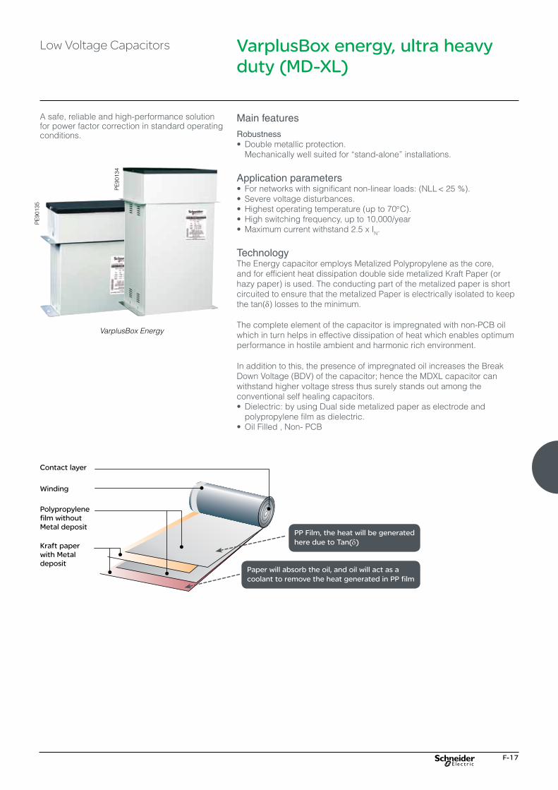
F-17
VarplusBox energy, ultra heavy duty (MD-XL)
PE
9013
5
PE
9013
4A safe, reliable and high-performance solution for power factor correction in standard operating conditions.
Main features
Robustness•� Double�metallic�protection.� Mechanically�well�suited�for�“stand-alone”�installations.�
Application parameters •� For�networks�with�significant�non-linear�loads:�(NLL�<��25�%).•� Severe�voltage�disturbances.•� Highest�operating�temperature�(up�to�70°C).•� High�switching�frequency,�up�to�10,000/year•�Maximum�current�withstand�2.5�x�IN.
Technology The Energy capacitor employs Metalized Polypropylene as the core, and for efficient heat dissipation double side metalized Kraft Paper (or hazy paper) is used. The conducting part of the metalized paper is short circuited to ensure that the metalized Paper is electrically isolated to keep the tan(δ) losses to the minimum.
The complete element of the capacitor is impregnated with non-PCB oil which in turn helps in effective dissipation of heat which enables optimum performance in hostile ambient and harmonic rich environment.
In addition to this, the presence of impregnated oil increases the Break Down Voltage (BDV) of the capacitor; hence the MDXL capacitor can withstand higher voltage stress thus surely stands out among the conventional self healing capacitors.•� Dielectric:�by�using�Dual�side�metalized�paper�as�electrode�and�
polypropylene film as dielectric.•�Oil�Filled�,�Non-�PCB
VarplusBox Energy
Low Voltage Capacitors
PP Film, the heat will be generated here due to Tan(δ)
Paper will absorb the oil, and oil will act as a coolant to remove the heat generated in PP film

F-18
VarplusBox energy, ultra heavy duty (MD-XL)
Technical specifications
Peak inrush current 400 x IN
Switching operations (max.) Up to 10 ,000 switching operations per yearMean Life expectancy Up to 160,000 hrs
Installation characteristicsMounting position Indoor, uprightFasteningEarthing
Mounting cleats
Terminals Bushing terminals designed for large cable termination and direct busbar mounting for banking
Safety featuresSafety Self-healing + Pressure-sensitive disconnector for each phase + Discharge deviceProtection IP20
ConstructionCasing Sheet steel enclosureDielectric Double metallized paper + polypropylene film
Impregnation Non-PCB, oil
General characteristics Standards IEC 60831-1/-2, IS 13340-1993/ IS 13341-1992Voltage range 440V, 480V, 525VFrequency 50 / 60 HzPower range 5 to 50 kVArLosses (dielectric) <�0.2�W�/�kVArLosses (total) <�0.5�W�/�kVArCapacitance tolerance -5%, +10%Voltage test Between terminals 2.15 x UN (AC), 10 s
Between terminal & container
≤ 525V: 3kv(AC),10s or 3.66kv(AC), 2s>�525V�:�3.66kv(AC),�10s�or�4.4kv(AC),2s
Impulse voltage ≤ 690V:8kvDischarge resistor Fitted, standard discharge time 60 s
Working conditionsAmbient temperature -25°C / +70°C (Class D)Humidity 95%Altitude 2,000 m above sea levelOvervoltage 1.00 x UN - Continuous
1.10 x UN - up to 12 hrs per day1.15 x UN - up to 30 min per day1.20 x UN - 5 min1.30 x UN - 1 min
Overcurrent Up to 2.5 x IN
Low Voltage Capacitors
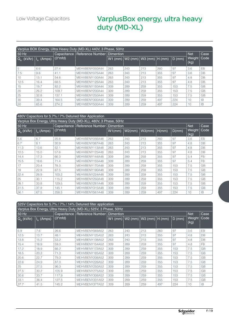
F-19
VarplusBox energy, ultra heavy duty (MD-XL)
Varplus BOX Energy, Ultra Heavy Duty (MD-XL) 440V, 3 Phase, 50Hz50 Hz Capacitance
(3*mfd)Reference Number Dimention Net
Weight(kg)
Case CodeQN (kVAr) IN (Amps) W1 (mm) W2 (mm) W3 (mm) H (mm) D (mm)
5 6.6 27.4 MEHVBENY050A44 263 243 213 260 97 3.6 EB7.5 9.8 41.1 MEHVBENY075A44 263 243 213 355 97 3.6 DB10 13.1 54.8 MEHVBENY100A44 263 243 213 355 97 4.8 DB12.5 16.4 68.5 MEHVBENY125A44 263 243 213 355 97 4.8 DB15 19.7 82.2 MEHVBENY150A44 309 289 259 355 153 7.5 GB20 26.2 109.7 MEHVBENY200A44 309 289 259 355 153 7.5 GB25 32.8 137.1 MEHVBENY250A44 309 289 259 355 153 7.5 GB30 39.4 164.5 MEHVBENY300A44 309 289 259 497 224 10 IB50 65.6 274.2 MEHVBENY500A44 309 289 259 497 224 10 IB
480V Capacitors for 5.7% / 7% Detuned filter ApplicationVarplus Box Energy, Ultra Heavy Duty (MD-XL), 480V, 3 Phase, 50Hz50 Hz Capacitance
(3*mfd)Reference Number Dimention Net
Weight(kg)
Case CodeQN (kVAr) IN (Amps) W1(mm) W2(mm) W3(mm) H(mm) D(mm)
5.6 6.7 25.8 MEHVBENY056A48 263 243 213 260 97 3.6 EB6.7 8.1 30.9 MEHVBENY067A48 263 243 213 355 97 4.8 DB11.3 13.6 52.1 MEHVBENY113A48 263 243 213 355 97 4.8 DB12.5 15.0 57.6 MEHVBENY125A48 263 243 213 355 97 4.8 DB14.4 17.3 66.3 MEHVBENY144A48 309 289 259 355 97 5.4 FB15.5 18.6 71.4 MEHVBENY155A48 309 289 259 355 97 5.4 FB17 20.4 78.3 MEHVBENY170A48 309 289 259 355 153 7.5 GB19 22.9 87.5 MEHVBENY190A48 309 289 259 355 153 7.5 GB22.4 26.9 103.2 MEHVBENY224A48 309 289 259 355 153 7.5 GB25 30.1 115.2 MEHVBENY250A48 309 289 259 355 153 7.5 GB28.1 33.8 129.5 MEHVBENY281A48 309 289 259 355 153 7.5 GB31.5 37.9 145.1 MEHVBENY315A48 309 289 259 355 153 7.5 GB56.1 67.5 258.5 MEHVBENY561A48 309 289 259 497 224 10 IB
525V Capacitors for 5.7% / 7% / 14% Detuned filter applicationVarplus Box Energy, Ultra Heavy Duty (MD-XL) 525V, 3 Phase, 50Hz50 Hz Capacitance
(3*mfd)Reference Number Dimention Net
Weight (kg)
Case CodeQN (kVAr) IN (Amps) W1 (mm) W2 (mm) W3 (mm) H (mm) D (mm)
6.9 7.6 26.6 MEHVBENY069A52 263 243 213 260 97 3.6 EB12.5 13.7 48.1 MEHVBENY125A52 263 243 213 355 97 4.8 DB13.8 15.2 53.2 MEHVBENY138A52 263 243 213 355 97 4.8 DB15.4 16.9 59.3 MEHVBENY154A52 309 289 259 355 97 4.8 FB17.2 18.9 66.2 MEHVBENY172A52 309 289 259 355 153 7.5 GB18.5 20.3 71.3 MEHVBENY185A52 309 289 259 355 153 7.5 GB20.6 22.7 79.3 MEHVBENY206A52 309 289 259 355 153 7.5 GB22.6 24.9 87.0 MEHVBENY226A52 309 289 259 355 153 7.5 GB25 27.5 96.3 MEHVBENY250A52 309 289 259 355 153 7.5 GB27.5 30.2 105.9 MEHVBENY275A52 309 289 259 355 153 7.5 GB30.6 33.7 117.9 MEHVBENY306A52 309 289 259 355 153 7.5 GB33.1 36.4 127.5 MEHVBENY331A52 309 289 259 355 153 7.5 GB37.7 41.5 145.2 MEHVBENY377A52 309 289 259 497 224 10 IB
Low Voltage Capacitors

F-20
VarplusBox mechanical characteristics
D
W1
W2
W3
Enclosure
Rubbergrommet for cable entry
H
DB
4027
30.e
ps
D
W1
W2
W3
Enclosure
Rubbergrommet for cable entry
H
DB
4027
31.e
ps
Case code: DB, EB, FB, GB & HB
Creepage distance 30 mmClearance
Phase to phase 25 mm (min.)Phase to earth 19 mm (min.)
Mounting details: mounting screw M6, 2 Nos.Case code
W1 (mm)
W2 (mm)
W3 (mm)
H (mm)
D (mm)
Weight(kg)
DB 263 243 213 355 97 4.8EB 263 243 213 260 97 3.6FB 309 289 259 355 97 5.4GB 309 289 259 355 153 7.5HB 309 289 259 455 153 8.0
Case Code: IB
Creepage distance 30 mmClearance
Phase to phase 25 mm (min.)Phase to earth 19 mm (min.)
Mounting details: mounting screw M6, 2 Nos.Case code
W1 (mm)
W2 (mm)
W3 (mm)
H (mm)
D (mm)
Weight(kg)
IB 309 289 259 497 224 10.0
Low Voltage Capacitors

G-1
Detuned Reactors
LV - Power Quality Products & Solutions
Detuned Reactors G-2

G-2
Detuned Reactors Detuned reactors
Detuned reactorsThe detuned reactor (DR) is designed to mitigate harmonics, improve power factor and avoid electrical resonance in low voltage electrical networks.
Main features• Special Design to ensure compactness with superior performance• High level of saturation - Linearity• High Grade Laminations in Magnetic Circuit• Easy pad termination and mounting• Over temperature protection• Robust inter-turn insulations• Low losses• Designed and tested as per IEC 60076 - 6
Technical DetailsStandards IS 5553, IEC 60076-6Description Three phase, dry, magnetic circuit, impregnatedRated Voltage ( Us) 440V ,50HzDe-tuning Factor(P) 5.67%(210Hz),7%(189Hz) ,14%(134Hz)kVAr range 5 to 100 kVArInsulation class HInductance tolerance - 3, + 5%Harmonic Level U3 = 0.5% x Us
U5 = 6.0% x UsU7 = 5.0% x UsU11 =3.5% x Us
Fundamental Current (Max) I1 = 1.06 x In( rated current)Duty Cycle (Irms) 100%Limit of Linearity L u0.95 x Ln upto 1.74 x InInsulation level 1.1KVDielectric test 50Hz between winding/earth
4kv, 1min
Degree of protection IP00Thermal protection Micro switch on terminal block 250V,AC,2A(NC)Winding material Aluminum wound
Detuned Factor (P) = 7%, Frequency (Fr)= 189Hz, 440V, Fn=50HzQN (kVAr) current
Irms (A)
Inductance (3*mH)
Reference Number
W (mm) W1 (mm) D (mm) D1 (mm) H (mm) Netweight(kgs)
5 7.1 9.04 LVR07050A44 240 200 140 125 220 10.710 14.2 4.52 LVR07100A44 240 200 140 125 220 12.712.5 17.7 3.61 LVR07125A44 240 200 140 125 220 16.215 21.3 3.01 LVR07150A44 240 200 140 125 220 16.220 28.4 2.26 LVR07200A44 240 200 140 125 220 21.225 35.5 1.81 LVR07250A44 240 200 140 125 220 21.250 70.9 0.90 LVR07500A44 260 200 140 125 270 32.275 106.4 0.60 LVR07750A44 260 200 140 125 270 43.2100 148.8 0.45 LVR07X00A44 350 200 160 125 320 44.2

G-3
Detuned reactors
Detuned Factor (P) = 5.67%, Frequency (Fr)= 210Hz, 440V , Fn=50HzQN (kVAr) current
Irms (A)Inductance (3*mH)
Reference Number W (mm) W1 (mm)
D (mm) D1 (mm)
H (mm) Netweight(kgs)
5 8.0 7.41 LVR05050A44 240 200 140 125 220 10.710 16.1 3.70 LVR05100A44 240 200 140 125 220 12.712.5 20.1 2.96 LVR05125A44 240 200 140 125 220 16.215 24.1 2.47 LVR05150A44 240 200 140 125 220 16.220 32.1 1.85 LVR05200A44 240 200 140 125 220 21.225 40.2 1.48 LVR05250A44 240 200 140 125 220 21.250 80.4 0.74 LVR05500A44 260 200 140 125 270 30.775 120.6 0.49 LVR05750A44 260 200 140 125 270 43.2100 160.7 0.37 LVR05X00A44 350 200 160 125 320 44.2
Detuned Factor (P) = 14%, Frequency (Fr)= 134Hz, 440V , Fn=50HzQN (kVAr) current
Irms (A)Inductance (3*mH)
Reference Number W (mm) W1 (mm)
D (mm) D1 (mm)
H (mm) Netweight(kgs)
5 6.6 19.59 LVR14050A44 240 200 140 125 220 10.510 13.2 9.79 LVR14100A44 240 200 140 125 220 1312.5 16.5 7.8 LVR14125A44 240 200 140 125 220 14.515 19.9 6.53 LVR14150A44 240 200 140 125 220 15.520 26.5 4.89 LVR14200A44 240 200 140 125 220 2725 33.1 3.91 LVR14250A44 240 200 140 125 220 27.250 66.2 1.95 LVR14500A44 260 200 140 125 270 37.275 99.3 1.30 LVR14750A44 260 200 140 125 270 60.2100 132.4 0.98 LVR14X00A44 350 200 160 125 320 61.2

G-4

H-1
Power Factor Controllers and Contactors
LV - Power Quality Products & Solutions
Varlogic APFC Relay H-2
Capacitor Duty Contactors H-6
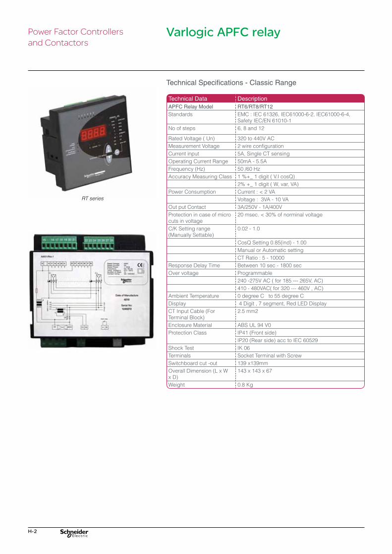
H-2
Varlogic APFC relayPower Factor Controllersand Contactors
Technical Data DescriptionAPFC Relay Model RT6/RT8/RT12
Standards EMC : IEC 61326, IEC61000-6-2, IEC61000-6-4, Safety IEC/EN 61010-1
No of steps 6, 8 and 12
Rated Voltage ( Un) 320 to 440V ACMeasurement Voltage 2 wire configurationCurrent input 5A, Single CT sensingOperating Current Range 50mA - 5.5AFrequency (Hz) 50 /60 Hz Accuracy Measuring Class 1 %+_ 1 digit ( V.I cosQ)
2% +_ 1 digit ( W, var, VA)Power Consumption Current�:�<�2�VA
Voltage : 3VA - 10 VAOut put Contact 3A/250V - 1A/400VProtection in case of micro cuts in voltage
20�msec.�<�30%�of�norminal�voltage
C/K Setting range (Manually Settable)
0.02 - 1.0
CosQ Setting 0.85(ind) - 1.00Manual or Automatic setting CT Ratio : 5 - 10000
Response Delay Time Between 10 sec - 1800 secOver voltage Programmable
240 -275V AC ( for 185 --- 265V, AC)410 - 480VAC( for 320 --- 460V , AC)
Ambient Temperature 0 degree C to 55 degree CDisplay 4 Digit , 7 segment, Red LED DisplayCT Input Cable (For Terminal Block)
2.5 mm2
Enclosure Material ABS UL 94 V0Protection Class IP41 (Front side)
IP20 (Rear side) acc to IEC 60529Shock Test IK 06Terminals Socket Terminal with ScrewSwitchboard cut -out 139 x139mmOverall Dimension (L x W x D)
143 x 143 x 67
Weight 0.8 Kg
Technical Specifications - Classic Range
RT series
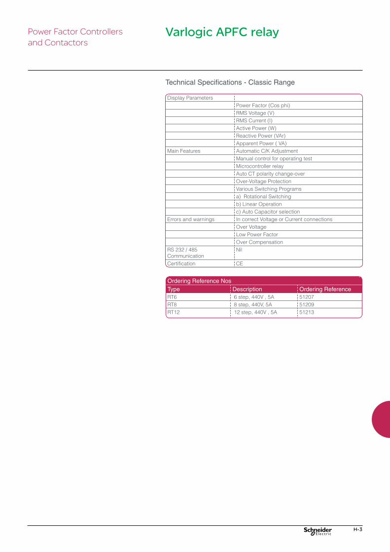
H-3
Varlogic APFC relayPower Factor Controllersand Contactors
Display ParametersPower Factor (Cos phi)RMS Voltage (V)RMS Current (I)Active Power (W)Reactive Power (VAr)Apparent Power ( VA)
Main Features Automatic C/K AdjustmentManual control for operating testMicrocontroller relayAuto CT polarity change-overOver-Voltage ProtectionVarious Switching Programs a) Rotational Switchingb) Linear Operationc) Auto Capacitor selection
Errors and warnings In correct Voltage or Current connectionsOver VoltageLow Power FactorOver Compensation
RS 232 / 485 Communication
Nil
Certification CE
Ordering Reference NosType Description Ordering ReferenceRT6 6 step, 440V , 5A 51207RT8 8 step, 440V, 5A 51209RT12 12 step, 440V , 5A 51213
Technical Specifications - Classic Range
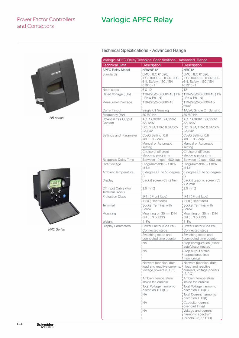
H-4
Varlogic APFC Relay Technical Specifications - Advanced Range Technical Data Description DescriptionAPFC Relay Model NR6/NR12 NRC12Standards EMC : IEC 61326,
IEC61000-6-2, IEC61000-6-4, Safety : IEC / EN 61010 -1
EMC : IEC 61326, IEC61000-6-2, IEC61000-6-4, Safety : IEC / EN 61010 -1
No of steps 6 & 12 12Rated Voltage ( Un) 110-220/240-380/415 ( Ph
- Ph & Ph - N)110-220/240-380/415 ( Ph - Ph & Ph - N)
Measurment Voltage 110-220/240-380/415 110-220/240-380/415-690V
Current input Single CT Sensing 1A/5A, Single CT SensingFrequency (Hz) 50 /60 Hz 50 /60 Hz Potential free Output Contact
AC: 1A/400V , 2A/250V, 5A/120V
AC: 1A/400V , 2A/250V, 5A/120V
DC: 0.3A/110V, 0.6A/60V, 2A/24V
DC: 0.3A/110V, 0.6A/60V, 2A/24V
Settings and Parameter CosQ Setting: 0.8 ind…..0.9�cap
CosQ Setting: 0.8 ind…..0.9�cap
Manual or Automatic setting
Manual or Automatic setting
Choice of different stepping programs
Choice of different stepping programs
Response Delay Time Between 10 sec - 600 sec Between 10 sec - 900 secOver voltage Programmable�>�110%�
of UnProgrammable�>�110%�of Un
Ambient Temperature 0 degree C to 55 degree C
0 degree C to 55 degree C
Display backlit screen 65 x21mm backlit graphic screen 55 x 28mm
CT Input Cable (For Terminal Block)
2.5 mm2 2.5 mm2
Protection Class IP41 ( Front face) IP41 ( Front face)IP20 ( Rear face) IP20 ( Rear face)
Terminal Socket Terminal with Screw
Socket Terminal with Screw
Mounting Mounting on 35mm DIN rail ( EN 50022)
Mounting on 35mm DIN rail ( EN 50022)
Weight 1 Kg 1 KgDisplay Parameters Power Factor (Cos Phi) Power Factor (Cos Phi)
Connected steps Connected stepsSwitching steps and connected time counter
Switching steps and connected time counter
NA Step configuration (fixed/auto/disconnected)
NA Step output status (capacitance loss monitoring)
Network technical data : load and reactive currents, voltage,powers (S,P,Q)
Network technical data : load and reactive currents, voltage,powers (S,P,Q)
Ambient temperature inside the cubicle
Ambient temperature inside the cubicle
Total Voltage harmonic distortion THD(U)
Total Voltage harmonic distortion THD(U)
NA Total Current harmonic distortion THD(I)
NA Capacitor current overload Irms/I
NA Voltage and current harmonic spectrum (orders 3,5,7,11,13)
Varlogic APFC Relay
Technical Specifications - Advanced Range
Power Factor Controllersand Contactors
NR series
NRC Series

H-5
Main Features Insensitive to CT polarity Insensitive to CT polarityInsensitive to phase rotation polarity
Insensitive to phase rotation polarity
Manual control for operating test
Personalized step sequences possible
NA Manual control for operating test
NA 4 quadrant operation for generator application
NA Possibility of a dual cosQ target
Choice of different switching programs
Choice of different switching programs
a) Linear operation a) Linear operationb) Normal b) NormalC) Circular C) Circulard) optimal d) optimalLow power factor Low power factor
Alarms Hunting( unstable regulation)
Hunting( unstable regulation)
Abnormal cosQ Abnormal cosQOver compensation Over compensationOver current Over currentLow Voltage Low VoltageOver Voltage Over VoltageOver temperature Over temperatureTotal harmonic distortion Total harmonic distortionNA Capacitor current over
load ( I rms)NA Capacitor capacitance
lossLow current message Low current messageHigh current message High current messageNA Under Voltage message
Communication NA RS 485 connectionOptional Features NA Temperature external
probe
Ordering Reference NosType Description Ordering ReferenceNR6 6 step,LCD Display , 110V-
415V,5A52448
NR12 12 step, LCD Display, 110V-415V,5A
52449
NRC12 12 step,LCD Display, Dual PF setting, 110V-415V, 1A/5A
52450
Varlogic N accessories Description Ordering ReferenceNRC 12 Communication RS485
Modbus set for NRC1252451
Varlogic APFC Relay
Technical Specifications - Advanced Range
Power Factor Controllersand Contactors

H-6
Capacitor duty contactors
Special�contactors�LC1�D•K�are�designed�for�switching 3-phase, single- or multiple-step capacitor banks. They comply with standards IEC 60070 and 60831, NFC 54-100, VDE 0560, UL and CSA.
Contactor
Operating conditions There is no need to use choke inductors for either single or multiple-step capacitor banks.
Specifications These contactors are fitted with a block of early make poles and damping resistors, limiting the value of the current on closing to 60 IS max. This�current�limiting�increases�the�life�of�all�the�installation’s�components,�especially the fuses and capacitors.
TeSys capacitor duty contactors (AC control)• Special Contactors designed for switching 3 phase capacitors• Conformity to IEC Standards• Current limitation by the inbuilt damping resistors• 1NO + 1NC inbuilt auxiliary contact
Ordering Reference NosVoltage kVAr Auxiliary
contactsReference
440V, 50 Hz 12.5 kVAr 1 NO + 1 NC LC1DFK11*2 NC LC1DFK02*
16.7 kVAr 1 NO + 1 NC LC1DGK11*C2 NC LC1DGK02*C
20 kVAr 1 NO + 1 NC LC1DLK11*2 NC LC1DLK02*
25 kVAr 1 NO + 1 NC LC1DMK11*C2 NC LC1DMK02*C
33.3 1 No + 2 Nc LC1DPKB7C40 kVAr 1 NO + 2 NC LC1DTKB7C60 kVAr 1 NO + 2 NC LC1DWKB7C
*Coil Voltage CodeVoltage 110V 220V 415VLC1-�DFK�…..DMK�50/60Hz
F7 M7 N7
LC1DPK…..DWK�50�Hz F5 M5 N5
Power Factor Controllersand Contactors

I-1
Installation Guide and Annexures
LV - Power Quality Products & Solutions
Best Practices for Capacitors Installation I-2
Best Practices for APFC Panel Installation I-3
Best practices for detuned APFC panel installation I-4
Important Formulas I-5

I-2
TerminalsDouble Fast-On + CableFor lower ratings double fast-on terminals with cables are provided (for rating�<=10kVAr)
CLAMPTITE terminalsThe unique finger-proof CLAMPTITE termination is fully integrated with discharge resistors and allows suitable access to tightening and ensures cable termination without any loose connections. Once tightened, the design guarantees that the tightening torque is always maintained. (for rating�>10kVAr,�up�to�30kVAr)
STUD Type terminals• This type of terminals are used for proper current handling capabilities
in capacitors of 40 & 50kVAr
Electrical connection•�Select the cable cross section depending on the kVAr & voltage rating•�User is recommended to use a cable of minimum temperature withstand
capacity of 90°C. (Recommended is 105°C)•�Remove conductor insulation of the cable only. 10mm for connection.•�Suitable size lugs have to be used with connecting cable to capacitor
terminals in order to avoid heat generation due to improper contacts, in case of VarplusBox or Stud type VarplusCan.
•� Insert conductor fully inside the clamp terminal to ensure that no single strand to come out from the slot, in case of clamp type terminals.
•�Please ensure proper tightness when a screw driver is used to avoid loose termination.
•�Apply a torque of 2.5Nm to tighten the CLAMPTITE terminal•�Apply a torque of 20Nm to tighten the Stud type terminal•�For tightening the VarplusBox terminal studs apply a torque of > For M6 studs - 4 Nm > For M8 studs - 8 Nm > For M10 studs - 12 Nm
Mounting•�Varplus capacitors can be mounted alone or in a row.•�Position: > SDuty & Energy : upright > HDuty : upright or horizontal•�Capacitor body should be earthed at bottom.•�Capacitor shall be installed in dry place away from heat generating
source & avoid dusty atmosphere•�Provide proper cross ventilation for heat conduction•�Apply a tightening torque of 8Nm to fix the VarplusBox capacitor on the
mounting plates.•� Tightening torque of 10Nm to be applied on Hexagonal mounting nut for
VarplusCan(see picture in the left).
Best practices for capacitors installation
Installation Guideand Annexures
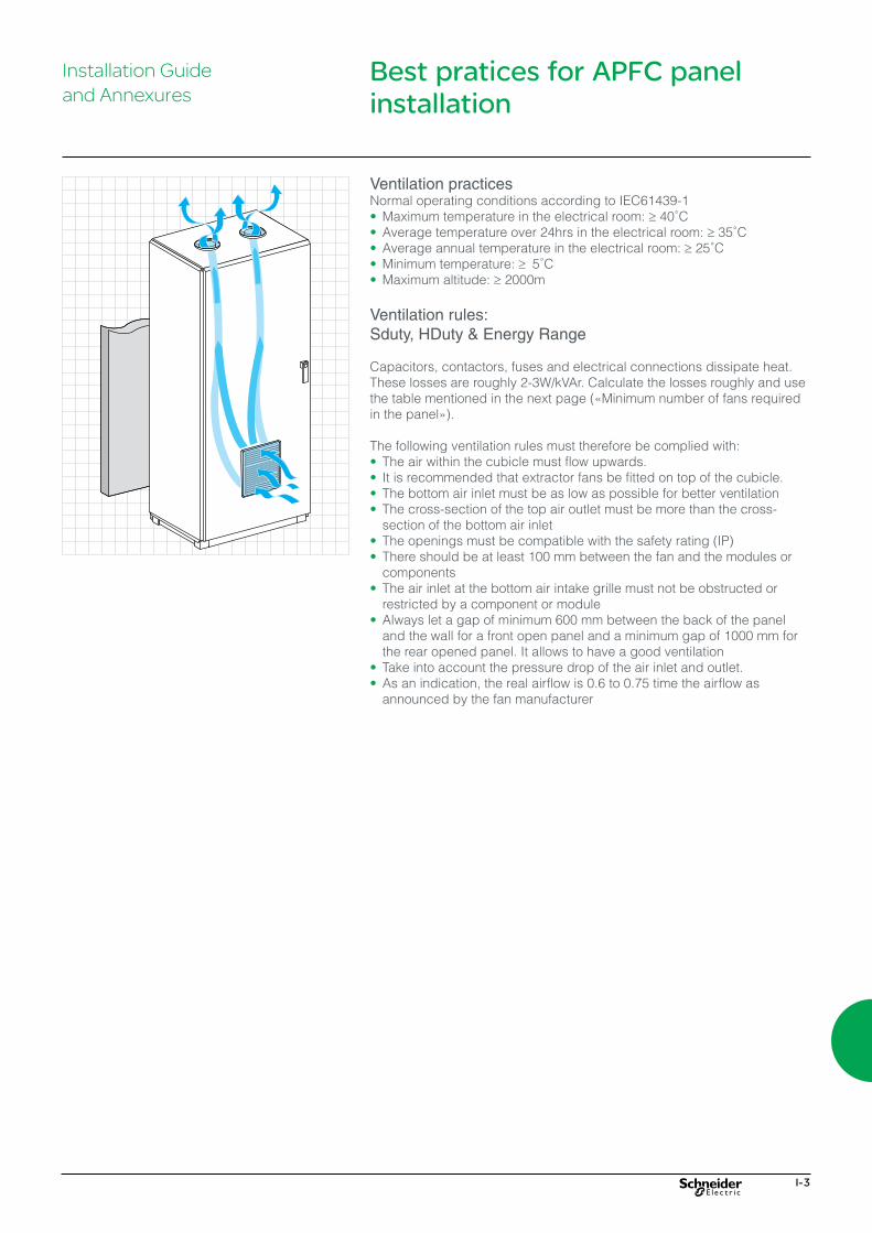
I-3
Best pratices for APFC panel installation
Installation Guideand Annexures
Ventilation practicesNormal operating conditions according to IEC61439-1•�Maximum temperature in the electrical room: ≥�40˚C•�Average temperature over 24hrs in the electrical room: ≥�35˚C•�Average annual temperature in the electrical room: ≥�25˚C• Minimum temperature: ≥ 5˚C•�Maximum altitude: ≥ 2000m
Ventilation rules:Sduty, HDuty & Energy Range
Capacitors, contactors, fuses and electrical connections dissipate heat. These losses are roughly 2-3W/kVAr. Calculate the losses roughly and use the�table�mentioned�in�the�next�page�(«Minimum�number�of�fans�required�in�the�panel»).
The following ventilation rules must therefore be complied with:•� The air within the cubicle must flow upwards.•� It is recommended that extractor fans be fitted on top of the cubicle.•� The bottom air inlet must be as low as possible for better ventilation•� The cross-section of the top air outlet must be more than the cross-
section of the bottom air inlet•� The openings must be compatible with the safety rating (IP)•� There should be at least 100 mm between the fan and the modules or
components•� The air inlet at the bottom air intake grille must not be obstructed or
restricted by a component or module•�Always let a gap of minimum 600 mm between the back of the panel
and the wall for a front open panel and a minimum gap of 1000 mm for the rear opened panel. It allows to have a good ventilation
•� Take into account the pressure drop of the air inlet and outlet.•�As an indication, the real airflow is 0.6 to 0.75 time the airflow as
announced by the fan manufacturer
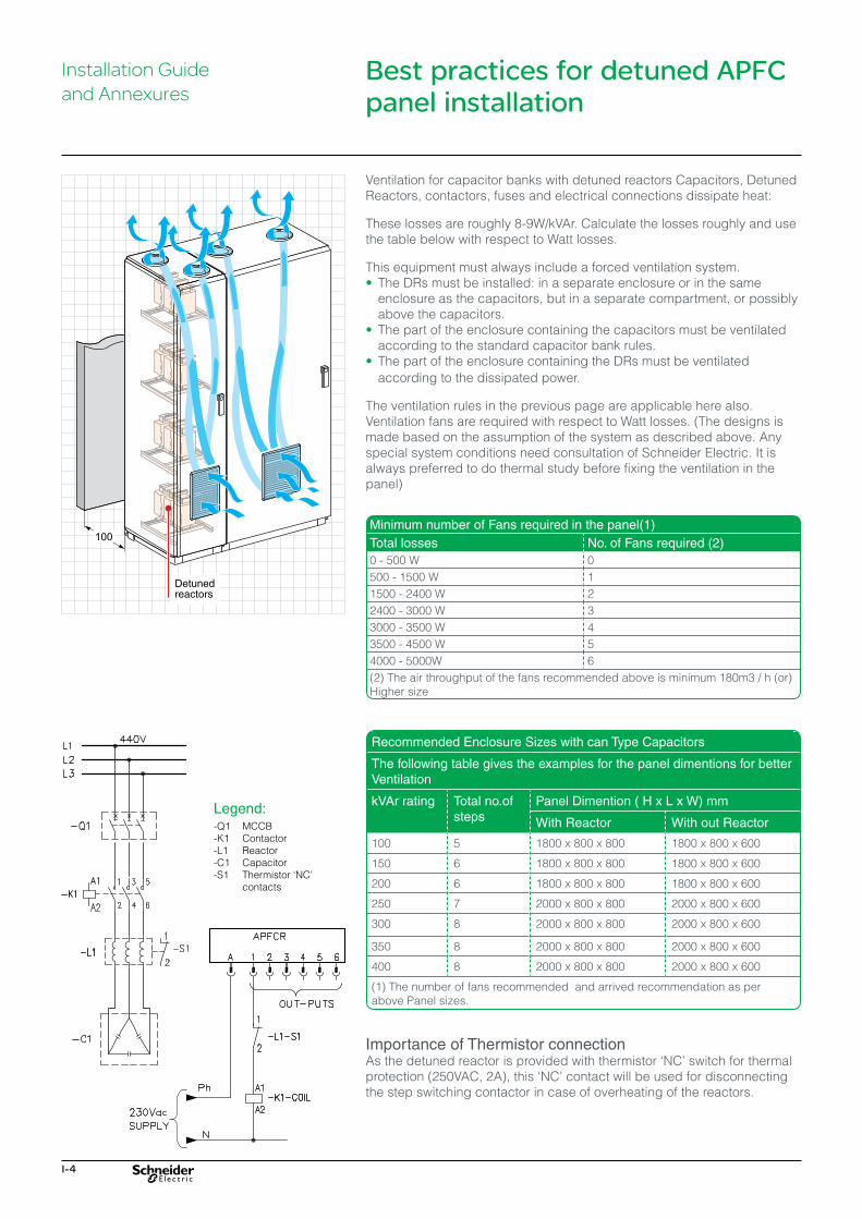
I-4
Ventilation for capacitor banks with detuned reactors Capacitors, Detuned Reactors, contactors, fuses and electrical connections dissipate heat:
These losses are roughly 8-9W/kVAr. Calculate the losses roughly and use the table below with respect to Watt losses.
This equipment must always include a forced ventilation system.•� The DRs must be installed: in a separate enclosure or in the same
enclosure as the capacitors, but in a separate compartment, or possibly above the capacitors.
•� The part of the enclosure containing the capacitors must be ventilated according to the standard capacitor bank rules.
•� The part of the enclosure containing the DRs must be ventilated according to the dissipated power.
The ventilation rules in the previous page are applicable here also.Ventilation fans are required with respect to Watt losses. (The designs is made based on the assumption of the system as described above. Any special system conditions need consultation of Schneider Electric. It is always preferred to do thermal study before fixing the ventilation in the panel)
Best practices for detuned APFC panel installation
Installation Guideand Annexures
Minimum number of Fans required in the panel(1)Total losses No. of Fans required (2)0 - 500 W 0500 - 1500 W 11500 - 2400 W 22400 - 3000 W 33000 - 3500 W 43500 - 4500 W 54000 - 5000W 6(2) The air throughput of the fans recommended above is minimum 180m3 / h (or) Higher size
Recommended Enclosure Sizes with can Type Capacitors
The following table gives the examples for the panel dimentions for better Ventilation
kVAr rating Total no.of steps
Panel Dimention ( H x L x W) mm
With Reactor With out Reactor
100 5 1800 x 800 x 800 1800 x 800 x 600
150 6 1800 x 800 x 800 1800 x 800 x 600
200 6 1800 x 800 x 800 1800 x 800 x 600
250 7 2000 x 800 x 800 2000 x 800 x 600
300 8 2000 x 800 x 800 2000 x 800 x 600
350 8 2000 x 800 x 800 2000 x 800 x 600
400 8 2000 x 800 x 800 2000 x 800 x 600
(1) The number of fans recommended and arrived recommendation as per above Panel sizes.
Importance of Thermistor connectionAs�the�detuned�reactor�is�provided�with�thermistor�‘NC’�switch�for�thermal�protection�(250VAC,�2A),�this�‘NC’�contact�will�be�used�for�disconnecting�the step switching contactor in case of overheating of the reactors.
Legend:-Q1 MCCB-K1 Contactor-L1 Reactor-C1 Capacitor-S1� Thermistor�‘NC’�
contacts

I-5
Important Formulas
Formula - 1The kVAr of capacitor will not be same if voltage applied to the capacitor and frequency changes. The example given below shows how to calculate capacitor power in kVAr from the measured values at site and name plate details.
QM =(fN / fN) x (UM / UN)2 x QN
UN = Rated Voltage
fN = Rated Frequency
QN = Rated power
UM = Measured voltage
fM = Measured frequency
QM = Available power in kVAr
Example:1. Name plate details - 15kVAr, 3 phases, 440V, 50Hz capacitor. Measured voltage - 425VMeasured frequency - 48.5Hz
QM =(fN / fN) x (UM / UN)2 x QN
QM = (48.5/50) x (425 / 440 )2 x 15 = 13.57kVAr.
2. Name plate details - 25kVAr, 3 phases, 480V, 60Hz capacitor. Measured voltage - 464VMeasured frequency - 59.5Hz
QM =(fN / fN) x (UM / UN)2 x QN
QM = (59.5/60) x (464/480 )2 x 15 = 23.16kVAr.
Formula - 2The current of capacitor will not be same if voltage applied to the capacitor and frequency changes. The example given below shows how to calculate capacitor current from the measured value at site.
UN = Rated Voltage
fN = Rated Frequency
IN = Rated Current
UM = Measured voltage
fM = Measured frequency
IM = Capacitor Current
Example:Consider a capacitor of 15 kVAr, 440V, 50 Hz, 3 Phase Capacitor Rated Current from name plate = 19.68A
Measured Values are: Voltage : 425V , Frequency : 49.5 Hz,
IM = IR( )UM x fM)
UR x fR)
= 18.43A
IM = 19.68( )425 x 48.5
440 x 50
Note: Please ensure that the measurement is done using true RMS clamp meter
Installation Guideand Annexures

I-6
Important formulas
Formula - 3Formula for calculating rated current of capacitor with rated supply voltage and frequency.
IN =kVAr x 103 / (√3 x UN)
Example
1. 50 kVAr, 3 phase, 440V, 50Hz capacitor.IN = kVAr x 103 / (√3x UN)lN = (50 x 1000) / (1.732 x 400)lN = 65.61 A
2. 37.7 kVAr, 3 phases, 525V, 50Hz capacitor.IN= kVAr x 103 / (√3x UN)lN= (37.7 x 1000) / (1.732 x 525)IN = 41.45 A
Formula - 4The capacitance value of a capacitor can be calculated using following formulae for delta connected 3ph capacitor.
Assume that capacitance of the three delta connected capacitors are C as shown in the figure.
C =QN x 109 / (4TTfNUN2) for 3 phase capacitor.
Example
1. 15 kVAr, 3 phases, 415V, 50Hz capacitorC = 15 x 109 / (4x3.142 x 50 x (415 x 415)) = 138.62mF
2. 15 kVAr, 3 phases, 440V, 50Hz capacitorC = 15 x 109 / (4x 3.142 x 50 x (440 x 440)) = 123.31mF
Formula - 5kVAr calculation from the measured capacitance value of a capacitor.
QM =2/3 x (Ca + Cb + Cc) x UN2 x (2TTfN) / 109 for 3 phase capacitor.
Example
1. Consider you have measured a capacitor rated for 440volts, 50Hz where in measured capacitance value is as follows:
� •� 197mf (between R & Y phase) - Ca� •� 196mf (between B & Y phase) - Cb� •� 200mf (between R & B phase) - CcQM = 2/3 x (Ca + Cb + CC) x UN
2 x (2TTfN) / 109
QM = 2/3 x (197+196+200) x (4402) x 2 x 3.14 x 50 / 109 = 24.04kVAr
2: Consider you have measured a capacitor rated for 480V ,60Hz where in measured capacitance value is as follows.
� •� 236mf (between R & Y phase) - Ca� •� 238mf (between B & Y phase) - Cb� •� 237mf (between R & B phase) - CcQM = 2/3 x (Ca + Cb + Cc) x UN
2 x (2TTfN) / 109
QM = 2/3 x (236+238+237) x (4802) x 2x3.14 x 60/109 = 41.19kVAr
The tolerance of capacitance of a capacitor is -5% to +10% of capacitor as specified in the IEC Standards.


Schneider Electric India Pvt. Ltd.
Corporate office9th Floor, DLF Building No.10, Tower C, DLF Cyber City, Phase II, Gurgaon - 122002, HaryanaTel: 0124 3940400, Fax: 0124 4222036www.schneider-electric.co.inCustomer Care Centre: Toll-free numbers: 1800 103 0011, 1800 425 4272 General number: 0124 4222040Email: [email protected]
Make the most of your energySM