l.u.s.tneiwpcc.org/lustlineold/lustline_pdf/lustline_61.pdf · lustline bulletin 61 • may 2009...
TRANSCRIPT

New England Interstate 116 John StreetWater Pollution Control Lowell, MassachusettsCommission 01852-1124
Bulletin 61May2009
A Report On Federal & State Programs To Control Leaking Underground Storage Tanks
www.neiwpcc.org/lustline
L.U.S.T.LINETen years ago, USEPA’s Clean Air Act Advisory Committee Panel on Oxygenate Use in Gasoline, better known as the Blue Ribbon Panel, announced its findings and recommendations. In its report the panel noted that the introduction of reformulated gasoline (RFG) “has had substantial air quality benefits, but has also raised significant questions that should be answered before the widespread use of any new, broadly used product. The unanticipated effects of RFG [specifically, MtBE] on groundwater high-light the importance of exploring the potential for adverse effects in all media (air, soil, and water), and on human and ecosystem health, before the launch of any such product.” The report urged us to “build on existing public health surveillance systems to measure the broader impact (both beneficial and adverse) of changes in gasoline formulations on public health and the environment.”
Well here we are in 2009, scrambling to deal with transformative new Congressional fuel mandates for the increased use of renewable fuels. While the move to renewable fuels is laudable in the name of weaning ourselves from petroleum and gaining self-sufficiency, the synchronization with regard to our goals and the hurdles in the path of carrying out those goals may from time to time be, shall we say, disappointing. Our new renewable fuels marching orders are already having an impact on many sectors of our economy, not the least of which is the storage of these fuels. Yet, these marching orders do not specifically mandate that we take the steps needed to anticipate the effects of these fuels on our UST infrastructures in order to protect our groundwater.
USEPA’s Office of Underground Storage Tanks (OUST) is coordinating with other USEPA offices, states,
industry, standard-making organizations, and other federal agencies to work through the
myriad of biofuel-related issues. Collabora-tion with these groups will help OUST better under-stand the impact of new fuels and new fuel blends on existing UST infrastructure and how releases of these
fuels will affect remediation efforts. As you will see in the following articles by our
UST/LUST-related industry and regulatory friends, the job of characterizing and anticipating the ramifica-tions of these mandates and the associated new and
emerging fuels is, to say the least, complex and daunt-ing. While much of the discussion centers on ethanols, the
concerns and issues raised apply to any new biofuel that may be stored in an underground storage tank system.
We thank all who have helped us pull this overview together and we welcome your thoughts and comments.
TangledWebofNew-FuelMandates
CAMultimediaReviewforNewFuels
EnvironmentalImpactsofFutureFuels
Fuels—APetroleumEquipmentPerspective
ChallengesforPetroleumMarketers
StateUST/LUSTProgramNew-FuelDilemmas
ScreeningCriteriaforVaporIntrusionPathway
PrimerforNextGenerationofTankPeople-PartII
OutdatedEquipmentonNWGLDEList
Inside2
4
5
6
7
9
11
15
19
B
E
When Reality Gets in the Way of Good Intentions UST/LUST Stakeholders Weigh In on Biofuels
???

�
LUSTLine Bulletin 61 • May 2009
L.U.S.T.LineEllen Frye, Editor
Ricki Pappo, LayoutMarcel Moreau, Technical Adviser
Patricia Ellis, PhD, Technical AdviserRonald Poltak, NEIWPCC Executive Director
Deb Steckley, USEPA Project OfficerLUSTLine is a product of the New England Interstate Water Pollution Control Commis-
sion (NEIWPCC). It is produced through cooperative agreements (US-83384301 and US-83384401) between NEIWPCC and the
U.S. Environmental Protection Agency.LUSTLine is issued as a communication
service for the Subtitle I RCRA Hazardous & Solid Waste Amendments
rule promulgation process. LUSTLine is produced to promote
information exchange on UST/LUST issues. The opinions and information stated herein are those of the authors and do not neces-sarily reflect the opinions of NEIWPCC.
This publication may be copied. Please give credit to NEIWPCC.
NEIWPCC was established by an Act of Congress in 1947 and remains the old-
est agency in the Northeast United States concerned with coordination of the multi-
media environmental activities of the states of Connecticut, Maine, Massachusetts, New Hampshire,
New York, Rhode Island, and Vermont.
NEIWPCC116 John Street
Lowell, MA 01852-1124Telephone: (978) 323-7929
Fax: (978) [email protected]
LUSTLine is printed on recycled paper
Under the Renewable Fuels Standard (RFS) adopted in 2005 (Energy Policy Act of
2005, aka EPACT 2005) and updated in 2007 (Energy Independence and Security Act of 2007, aka EISA 2007), Congress committed the U.S. to a substantial (five-fold) increase in its use of biofuels by 2022. So, begin-ning in 2005, ethanol refineries began springing up in cornfields all over the Midwest. Demand for ethanol was particularly great while crude prices were high—ethanol was cheaper so it made sense to blend it in gasoline.
More recently, however, demand for gasoline has decreased due to high prices and a declining economy. As crude and gasoline prices dropped, ethanol prices didn’t. Demand for ethanol, particularly when it costs more per gallon than gasoline, didn’t keep up with all that new ethanol production, and as a result, about
20 percent of U.S. ethanol refineries are currently idle and many compa-nies have filed for bankruptcy.
A new report, issued in April by the Congressional Budget Office (CBO), details the plight of the etha-nol industry and suggests that the current economic environment has put all ethanol producers in dire straits. (See report at http://www.cbo.gov/ftpdocs/100xx/doc10057/04-08-Ethanol.pdf) The profitability of corn-based ethanol sits at the inter-section of corn and gasoline prices. Oh, and one other thing, EISA 2007 has a quota of 100 million gallons of cellulosic ethanol by 2010. We’re not on target to meet that goal (not even close)…and at what cost per gallon?
WatchOutforthatBlendWall!EISA 2007 mandates that increasing amounts of ethanol be used in gaso-line in the future. But we’re about to crash up against what is known as the ethanol “blend wall” or “blend barrier.” That’s when the market for gasoline other than E85 has absorbed all the ethanol it can at the 10 per-cent-volume blending level.
We currently use about 140 bil-lion gallons of gasoline each year in the U.S. Thus we only need about 14 billion gallons of ethanol to convert the entire nation to E10. To reach the mandated 36 billion gallons of etha-nol in the fuel supply by 2022, we will either need to triple our gasoline consumption in the next 13 years (not likely or desirable) or else increase the percentage of ethanol in each gal-lon of gasoline that we use to some-thing like E30.
Furthermore, according to the Department of Energy, there are cur-rently about seven million flex-fuel vehicles (FFVs) on U.S. highways, most of which have never used a gal-lon of E85. (FFVs are alternative-fuel vehicles with an internal combustion engine designed to run on more than one fuel, usually gasoline blended with either ethanol or methanol fuel; both fuels are stored in a common tank.)
U.S. automakers have commit-ted to increasing production of FFVs,
but it will take a long time to get enough of them on the road to reach the 90–110 million of them needed to achieve renewable fuel objectives, not to mention increasing the num-ber of E85 fueling facilities from the current 2,000 facilities to the esti-mated 60,000 facilities that will be required.
Without storage tanks and dis-pensers capable of withstanding the higher concentrations of ethanol and cars capable of running on higher eth-anol fuel, the blend wall will prevent our meeting the ethanol-blending requirements of EISA 2007. Quoting then-presidential candidate Barack Obama in January 2007, “We’ve done a better job of focusing on production than we have on distribution” (Busi-ness Week, January 29, 2007).
TheEthanolIndustry’sWaiverApplicationBarring using ethanol as E85, the other way to avoid hitting the blend wall is to increase the volume of eth-anol that is allowed in conventional gasoline. Currently, up to 10 percent by volume is allowed in gasoline (EPA issued a waiver for 10 percent by volume ethanol blends in 1976). Growth Energy, on behalf of about 52 U.S. ethanol manufacturers, sub-mitted a request on March 6, 2009 to the USEPA Administrator to grant a waiver pursuant to Section 211 (f) (4) of the Clean Air Act, to allow the use of a blend of 15 percent ethanol in gasoline. This section of the CAA allows the USEPA Administrator to grant a waiver allowing the use of a fuel additive upon application that establishes that the use of the fuel additive “will not cause or con-tribute to the failure of any emis-sion-control device or system.” The Waiver Application and supporting documentation can be accessed at http://growthenergy.org/2009/e15/learn-more.asp.
According to the Waiver Request, federal case law indicates that waiver decisions are to be made “based on one criterion: a fuel additive’s effect on emission standards,” and that USEPA’s role is “to assess whether the
UST/LUST Stakeholders Weigh In on Biofuels
The Tangled Web of New-Fuel Mandatesby Patricia Ellis

�
May 2009 • LUSTLine Bulletin 61
additive’s emission products ‘causes or contributes’ to an emission control device’s ability to comply with the Act’s emission standards.”
On April 15, 2009, USEPA issued a request for comments on the pro-posed waiver request. The request for comments includes the following statement: “Although it is not a spe-cific criterion by which to evaluate a waiver request under section 211(f), any approved waiver request could require new program changes to accommodate this new fuel. USEPA seeks comments on the effect of a potential waiver for ethanol blends above 10 percent and up to 15 per-cent on the existing fuel programs (e.g., gasoline detergent certifica-tion, impact on underground stor-age tanks, etc.) and on the gasoline production, distribution and market-ing infrastructure.” At last, someone there in D.C. is thinking of us tank people! The public comment period ends on July 21, 2009. (For more on the Notice of Receipt of a Clean Air Act Waiver Application to Increase the Allowable Ethanol Content of
Gasoline to 15 Percent: Request for Comment, go to http://www.epa.gov/fedrgstr/EPA-AIR/2009/April/Day-21/a9115.pdf.)
Note that the Waiver Application does not seek to mandate the use of E15, but rather seeks to remove the barrier to its use. The applicants do not object to the continued avail-ability of E0 and E10 for use in small engines or other applications. How-ever, not all facilities contain blend-ing pumps, and few retailers would want to have to install separate fuel tanks for each of these separate fuels.
NewBiofuelsInfrastructureReportOn April 16, the National Commis-sion of Energy Policy released a report by the Task Force on Biofuels Infra-structure (http://www.bipartisanpolicy.org/ht/a/GetDocumentAction/i/10238). The report outlines what changes are needed to accommodate the RFS mandates, from transportation needs right down to the gas stations. Certi-fied equipment needs to be available that can withstand storage of bio-
fuels, and adequate lead-time (and financial assistance?) is essential to allow these upgrades. Given the aver-age expected lifespan of 20 years for underground equipment and 12 years for dispensers, we might be ready to start dispensing higher ethanol con-centration blends of gasoline in 10 to 15 years! Heck, in Delaware we still have somewhere around 100 pre-1985 fiberglass tanks in use, which may not even be compatible with E10. We may just be waiting for these tanks to get all squishy and soft, or for the glue joints holding the piping together to fail. Or will it be some 10-cent plastic part that wasn’t able to stand up to increasingly higher amounts of etha-nol, causing a major release? Who’s going to pay? Legacy tank systems can’t be ignored. n
Patricia Ellis, Ph.D., is a hydrologist with the Delaware Department of
Natural Resources and Environment Control, Tank Management Branch. She writes the LUSTLine column
“WanderLUST,” and can be reached at [email protected].
CaliforniaApprovesaNewLow-CarbonFuelStandardOn April 24, 2009, the California Air Resources Board approved the Low-Carbon Fuel Standard (LCFS). The goal of the standard is to lower the “carbon intensity” of fuels sold in California 10 percent by 2020. It does this by using complex formulas to score each type of fuel based on its life-cycle emissions. Carbon intensity is calculated by comparing the amount of greenhouse gases (GHG) emit-ted by a fuel over its life cycle with the amount of energy that it produces. At issue for ethanol and other biofuels is the inclusion of indirect land-use effects in calculating a given fuel’s total GHG emissions—growing fuel on exist-ing farmland, plus the effect of deforestation caused by the need to bring additional land under cultivation as fuel crops displace food crops. The more sustainable fuels are referred to as “advanced biofuels,” which must have a 50 percent improvement over fossil fuels in terms of GHG contributions. Once indirect land-use effects are included, food-based fuels may no longer make the cut.
Growing food-or-fuel will have a significant land-use effect for corn ethanol, while having little effect for cellu-losic ethanol. Corn ethanol may not survive the analysis and qualify for California’s Low Carbon Fuel Standard, and could potentially be “banned” from California. A working group charged with studying indirect land-use change must make a report by January 2011.The Califor-nia LCFS regulations will take effect in 2011. It is expected that a large group of Eastern states will adopt California’s standard.
USEPAIssuesNoticeofRFS2ProposedRulemakingOn May 5, 2009, EPA issued a Notice of Proposed Rule-making for the Renewable Fuels Standard (RFS2), as required by EISA 2007. The revised statutory require-ments specify the volumes of various types of renewable fuels that must be used in transportation fuel each year with the volumes increasing over time. The proposed standard will also address greenhouse gas emission thresholds for various classes of renewable fuels. The greenhouse gas emission assessments must evaluate the full life-cycle emission impacts of fuel production, including both direct and indirect emissions and signifi-cant emissions from land-use changes.
Mention is made of the potential for leaks from USTs way in the back of the proposed rule. It states: “With the increasing use of ethanol in the fuel supply nationwide, it is important to understand the impact of ethanol on the existing tank infrastructure. Given the corrosivity of etha-nol, there is concern regarding the increased potential for leaks from existing gas stations and subsequent impacts on drinking water supplies. In 2007, there were 7,500 reported releases from underground storage tanks. There-fore, EPA is undertaking analyses designed to assess the potential impacts of ethanol blends on tank infrastructure and leak-detection systems and determine the resulting water quality impacts.”
Documents relating to the proposed rulemaking may be found at http://www.epa.gov/otaq/renewablefuels/#regulations. n

�
LUSTLine Bulletin 61 • May 2009
In 1999, the California Legislature recognized the need for a mul-timedia environmental impacts
review of all new motor-vehicle fuels (additives to gasoline and diesel as well as new “low-carbon” fuels) and directed the California Environmen-tal Protection Agency (CalEPA) to establish a multimedia evaluation process to meet that need.
Key goals of that multimedia process include:• A streamlined, one-stop, compre-
hensive environmental review and assessment of significant risks posed by new fuels and fuel addi-tives; a process designed to reduce risks to human health and the environment potentially resulting from a single media review.
• A consistent, well-defined, staged process with continuous feed-back loops designed to reduce both short-term evaluation costs to the applicant (they may exit the process at any point based on feedback from the multimedia working group on projected costs and likelihood of success), as well as a process designed to reduce long-term costs of potential policy reversals resulting from impacts discovered after commercializa-tion (e.g., MtBE).
To manage the evaluation pro-cess a multimedia working group (MMWG) was formed to assist an applicant with the requirements of the process and to ensure the ade-quacy of data submitted, and on the basis of those data make recommen-dations to the Environmental Policy Council of CalEPA regarding any “significant adverse impact on public health or the environment including air, water, [and] soil that may result from the production, use, [and] disposal of the motor vehicle fuel.” The MMWG is chaired by the Air Resources Board and comprised of engineers and scientists representing the Water Resources Control Board, Integrated
1. Tier I: The applicant must submit a literature search report to the MMWG for comment and identi-fication of data gaps of significant concern to one or more MMWG members.
2. Tier II: Based on MMWG com-ments, the applicant must develop and execute experimental designs to fill those data gaps.
3. Tier III: The applicant must pre-pare a comprehensive risk assess-ment evaluation of the proposed fuel, based on data from both the Tier I literature search and the Tier II experiments.
4. The MMWG prepares recom-mendations based on the Tier III report.
5. The MMWG recommendations are subjected to an external peer review.
6. For a final determination the MMWG submits their recommen-dations and the peer review com-ments to the Environmental Policy Council, which consists of the Sec-retary for Environmental Protec-tion and the Chairpersons of all member boards, directorates, and offices represented in the MMWG.
The MMWG provides con-tinuous feedback to the applicant throughout the process. At each step the MMWG meets with the applicant to discuss issues and provide writ-ten comments on the adequacy of the applicant’s approach, methodology, and data.
Fuels currently undergoing review and in the pipeline for review include biodiesel, butanol, E10, E85, and LNG/CNG, as well as several diesel additives. The process is still evolving; however, the typical review time line is two to three years. The biodiesel evaluation, for example, is near the midpoint of Tier II; some aquatic toxicity tests are underway, and the air-emissions testing is near-ing completion. The completed lit-erature search on biodiesel’s adverse
Waste Management Board, Office of Environmental Health Hazard Assessment, Department of Toxic Substances Control, and the Depart-ment of Pesticide Regulation.
One of the MMWG’s first tasks was to develop a detailed guidance document, first drafted in 2006 and revised in 2008, to inform applicants about the process. The latest version may be found at http://www.arb.ca.gov/fuels/multimedia/080608guidance.pdf.
The applicant is responsible for all costs of the evaluation process, as well as for collecting and presenting data to the MMWG for review and comment. Tier I of the three-tier eval-uation is a literature search, which at a minimum must consider:• Emissions of air pollutants, includ-
ing ozone, “criteria pollutants,” and greenhouse gases
• Contamination of surface water, groundwater, and soil
• Disposal or use of the byproducts and waste materials from the pro-duction of fuel.
Evaluations related to UST stor-age of a new fuel include:• Material compatibility • Marine and freshwater aquatic
toxicity • Fate and transport in soil • Effects on cleanup of unauthor-
ized releases • Fuel production water consump-
tion and wastewater discharge • Disposal of contaminated fuels
and soils.• Others as required (e.g., one of
our current applicants may utilize a genetically modified organism in the fuel-production process. Exper-imental protocols for evaluation of potential adverse effects related to genetically modified organisms have not yet been developed, as this is our first such case).
TheEvaluationProcessThe MMWG uses the following three-tier, six-step process in making its evaluations:
UST/LUST Stakeholders Weigh In on Biofuels
MtBE? Never Again!California’s Multimedia Review Process for New Motor-Vehicle Fuelsby Robert Hodam

�
May 2009 • LUSTLine Bulletin 61
impacts, California Biodiesel Multime-dia Evaluation Tier I, January 16, 2009 Report, may be downloaded as a PDF file at http://www.arb.ca.gov/fuels/mul-timedia/multimedia.htm.
In the next issue of LUSTLine, I will discuss the testing (experimental plan) to which biodiesel is being sub-jected. Biodiesel is the furthest along of all the applicants and the candi-date fuel that poses the most elabo-rate challenges to the process and to the experimental plan research.
For further detail on California’s multimedia process, timeline, and
Automotive fuels are composed of hundreds of compounds and the formulations aren’t uniform;
they vary geographically and seasonally and sometimes specifically in response to regulatory requirements. As a result, very few state underground storage tank (UST) regulators know what is in the fuel stream at a service station or bulk plant in their state. Consequently, dif-ficulties abound in anticipating which compounds to sample, choosing ana-lytical methods, and eventually select-ing technologies for effective remediation in the case of a release. We face the new challenge of determining the correct approach to protecting human health and the environment that includes prioritiza-tion of chemicals based on toxicity, fate, and transport in the subsurface. This article touches on some basic new fuel-related concerns in leaking underground storage tank (LUST) site assessment and remediation, particularly those associ-ated with ethanol in gasoline.
MulticomponentCompoundsFor the most part, our liquid fuels are multicomponent mixtures that can include hundreds of compounds. Some are natural components of crude oil, some are produced from the crude during refining, and some are introduced as additives. On the petroleum supply side, there are numerous benefits from this situ-ation—the availability of variable sources of crude oil, the ability to make adjustments with respect to engine performance under vary-
or blended) with water, there is a major distinction in its behav-ior. The chemical forms a separate phase from water that persists in the environment. This phase forms our familiar light nonaqueous-phase liquid (LNAPL), a characteristic of petroleum contamination from leak-ing UST systems.
Recent recognition of lead scav-engers such as ethylene dibromide (EDB) as persistent pollutants illus-trates this point. EDB is immiscible with water and has physical-chemi-cal properties that are roughly simi-lar to benzene. Thus it partitions from gasoline much like benzene, another water-immiscible chemical. EDB differs from benzene because of its biotransformation pathway. In essence, the bromium in the com-pound causes it to degrade under reductive conditions, as opposed to the oxidative conditions required for benzene. Much of this can be pre-dicted in a general way. Specific field and laboratory studies are needed, however, to determine the rates of transformation and the potential for widespread plume persistence.
Likewise, our historic interest in BTEX contamination arises because benzene is a carcinogen. BTEX has a relatively high water solubility and volatility and is present in a signifi-cant amount in gasoline. Biodegra-dation, in many cases, reduces its extent, but the combination of these factors: water immiscibility, solubility,
UST/LUST Stakeholders Weigh In on Biofuels
Anticipating Environmental Impacts of Future Fuelsby Jim Weaver
fuels being evaluated, download an excellent presentation at www.arb.ca.gov/diesel/verdev/wn/asideco.pdf.
CanWeAffordNottoDoThis?Increasing numbers of new low-car-bon and reduced-emission motor-vehicle fuels and additives are being developed and introduced that must meet ever-stricter air-emission stan-dards. Yet without a comprehensive risk assessment of these new fuels before their commercial introduction, the chances of repeating another MtBE
debacle increase. Can we really afford not to conduct a multimedia envi-ronmental risk assessment of all fuels before they are introduced into the environment and stored in USTs? n
Robert Hodam is a chemical engineer with the UST Section of the California Water Resources Control Board. He is currently responsible for alternative fuels issues and represents the board on the CalEPA Multimedia Working
Group. He can be reached at [email protected].
ing operating conditions, and the flexibility to boost octane ratings to match modern engine requirements, to name a few.
On the regulatory side, we are concerned with how the components of these fuels enter the environment and behave when there is a release from the fuel-storage system. Once released into the environment, fuel constituents partition into different environmental compartments—air, water, and soil. We can predict some behavior of a multicomponent fuel, based on its chemical properties and our knowledge of how much of each is present. We have learned a lot about how fuels interact with the environment over the last 30 years, but this knowledge has limits. In addition to the examples mentioned above, ethanol has shown some char-acteristics that were predicted and others that were not.
WhatDeterminesFuelBehaviorintheSubsurface?The major properties that influence fuel-component behavior are solubil-ity, volatility, sorptivity, and biode-gradability. Along with the amount of each chemical present in the fuel, these properties determine how the chemical interacts with the envi-ronment, including its persistence. As such, the properties can act as a screen for behavior.
For example, if the solubility of a compound is low, so that it is immiscible (i.e., cannot be mixed ■ continued on page 6

�
LUSTLine Bulletin 61 • May 2009
presence in fuel, and toxicity make it a candidate for our concern.
In these examples the com-pounds are all immiscible with water and, therefore, contribute in a simi-lar way to the separate phase NAPL (gasoline). In contrast compounds such as ethanol, that are miscible (i.e., can mix) with water, interrupt this paradigm and force us to con-sider phase separation and its impact on releases.
So,WhatAboutThoseAlcohols?Based on our knowledge, it was anticipated that the approximately 10 percent ethanol in E10 gasoline could cause BTEX plumes to extend farther out as microorganisms pref-erentially chowed down on the etha-nol and ignored the BTEX. In essence we have one component interfer-ing with our expected behavior of another. Our previous focus on indi-vidual components of fuel did not, however, provide all the information needed to assess the impacts from the newly added ethanol. Ultimately our understanding of this behavior required modeling and laboratory and field studies.
At high concentration, ethanol, in particular, causes a qualitative change in the behavior of a fuel. Field studies are beginning to show that the aqueous/ethanol phase associ-ated with an E95 spill hangs around in the vadose zone. Groundwater impacts, when they appear, are hap-pening months or years after the release. Some of this behavior may be predictable from knowledge of the composition and the chemical prop-erties. But would this entire scenario have been anticipated? Likely not.
So how would these scenarios change if we switched from ethanol to propanol or butanol? There are published phase-separation data for gasoline containing propanol and butanol. So far so good. Those data show that the alcohol tends to remain held in the phase-separated organic phase rather than the water, as does ethanol. From available information, can we predict the impact on vadose-zone transport, materials compatibil-ity, vapor releases, effectiveness of remedial technologies, and biotrans-formation pathways and rates?
Our 30 years of experience in dealing with these problems gives us some ability to predict some of the behavior of new fuels, but there are properties that aren’t predictable, such as the biodegradation rates in
Year after year, decade after decade, legislators and regula-tors pass new laws and regu-
lations that impact the petroleum marketing equipment industry. The trouble is, they seldom tell us what they have in mind until the very last minute. But that’s okay, we in the petroleum equipment industry are used to it.
Go back with me and think about what we have experienced over the last two generations. Fuel with lead. Unleaded fuel. Half-pricing. Pricing over $1 a gallon. Vapor recovery. Pric-ing over $2 a gallon. Metrification. Demetrification. Unattended fueling
groundwater. This means that as a regulatory and scientific community we need to take a proactive look at the coming composition of fuels and their potential impacts. This work is partially underway in various places. Some states are looking more closely at their gasoline supply as is the USEPA. (See USEPA’s ongoing gaso-line composition study at: http://www.epa.gov/athens/research/regsupport/gas-oline.html). Transport and transfor-mation studies are being supported by USEPA, the American Petroleum Institute (API), and some states, and are being conducted by USEPA ORD and universities. Take home mes-sage? As fuel compositions continue to change in the coming years, we need to be moving quickly to supply the needed and unpredicted scien-tific information. n
Jim Weaver, Ph.D., is a hydrologist with USEPA’s Office of Research and Development. He can be reached at
This paper has been reviewed in accor-dance with the U.S. Environmental Protection Agency’s peer and adminis-trative review policies and approved for publication. Mention of trade names or commercial products does not constitute endorsement or recommendation for use.
UST/LUST Stakeholders Weigh In on Biofuels
Fuels of the Future Are Here Today and, Again, We’re Not Ready—A Petroleum Equipment Perspectiveby Robert Renkes
open to the public. Gasohol. Refor-mulated fuels. Underground storage tank regulation. Aboveground storage tanks at retail sites. Pricing over $3 per gallon. Gasoline with MtBE. Onboard canisters. Low-sulfur diesel. Ultra-low sulfur diesel. Back to ethanol. Biodie-sel. E85. Enhanced vapor recovery. Pricing over $4 a gallon. Renewable fuel mandates. Diesel-exhaust fluid. Except for the unattended fueling, most of this stuff was not the equip-ment industry’s idea!
Now we are on the verge of add-ing more stuff to the fuel. It looks cer-tain that E10 will turn into E12 or E15 or something else. Biodiesel B3 turns
into B5 and now we are looking at B10, B15, B20, or better. One problem solved, another problem, perhaps, created.
Sometimes political and regu-latory decision makers think to ask folks in the petroleum equipment industry whether or not their prod-ucts can store, meter, and/or dis-pense these fuels before they are introduced in the market. But most of the time these questions are not asked. For instance, USEPA’s E15 waiver decision cannot include con-sideration of equipment compat-ibility, although they say they are allowed to think about it. (See “The
■ EnvironmentalImpactsfrom page 5

�
May 2009 • LUSTLine Bulletin 61
Tangled Web of New Fuel Mandates” on page 2). But usually it really doesn’t matter because the legislators or regulators are calling the shots. We can take some solace that we aren’t alone; not many people ask weight and measures, listing agencies, work groups, product producers, or state regulators what they think either.
So that’s the nature of the beast. We do the best we can and move on. We still don’t have a listed E85 dis-penser, but we dispense E85 anyway, and one day we’ll have a standard.
the country use 36 billion gallons of renewable fuels by 2022. Corn-based ethanol may be used to make up 15 billion gallons of this requirement, 21 billion gallons must come from non-corn-based ethanol, and the remain-ing one billion gallons must come from bio-based diesel.
Thus, in the not-so-distant future, we expect to see more types of transportation fuels, including those derived from non-ethanol sources, entering the marketplace as replacements for fossil fuels. As that happens, the most likely future sce-nario involves the establishment of retail transportation fuel stations that dispense numerous different types of fuel. Some of these fuels are already in the proverbial pipeline and have been anticipated by manufactur-ers of retail petroleum equipment. Others are still in the development stages, rendering it impossible at this point for manufacturers to accurately anticipate future needs.
TakeEthanol,forExampleCurrently, in the U.S., no gasoline mixed with more than 10 percent ethanol can be dispensed to a non-flex-fuel vehicle, in accordance with Clean Air Act restrictions, because emission-control devices on these vehicles were designed to handle only up to 10 percent ethanol fuel blends. Additionally, a complete fuel-dispensing system listed for use with fuel containing ethanol at lev-
els greater than 10 percent does not currently exist. This is potentially problematic because the U.S. Occu-pational Health and Safety Admin-istration (OSHA) requires that all equipment used to dispense flam-mable liquids, including gasoline, be listed by a nationally recognized test-ing laboratory, such as Underwriters Laboratories (UL).
To meet the EISA renewable-fuel mandate, ethanol will have to surpass 10 percent of every gallon of gasoline dispensed. Therefore, either non-flex-fuel vehicles must be allowed to use greater than 10 percent ethanol or flex-fuel vehicles must make up a much greater per-centage of the nation’s vehicle fleet. If either of these scenarios does not happen to the extent necessary, there will be a greater supply of ethanol than can be accommodated by the gasoline market, which is colloqui-ally called the E10 blend wall.
The mandates in EISA for non-corn-based ethanol will be met pri-marily with cellulosic ethanol, which is, from a storage and dispensing infrastructure perspective, the same as corn-based ethanol, except derived from a different source. These man-dates call for 100 million gallons of cellulosic ethanol to be produced by the end of 2010. However, increas-ing production of cellulosic ethanol coming to market will only serve to hasten our encounter with the blend
UST/LUST Stakeholders Weigh In on Biofuels
New-Fuels Challenges for Petroleum Marketersby Brian T. Knapp
We’ll make some mistakes along the way, but that’s not (hopefully) fatal. We aren’t ready with listed equip-ment for E12 or E15, but we will be someday. Same thing with biodiesel; we don’t know all we should about biodiesel, but we’re learning.
Not everything comes tied up in a nice, neat package. Fuels of the future, like so many other things in our industry, will be upon us before we are ready for them. But that’s okay, it’s simply the way it is. We’re used to it. We’ll catch up. We’ll get there.
In the meantime, as the industry experiments with these new fuels in the field, we need to keep an extra-close eye on things. We will get things right sooner or later, learning some lessons the hard way as we travel that path, but we’ll get there. Like I said, it’s the best we can do. n
Robert N. Renkes is Executive Vice President with the Petroleum
Equipment Institute (PEI). He can be reached at [email protected].
As our government attempts to wean the country off tra-ditional sources of energy
in favor of renewable sources, it is necessary to consider the potential effects of this transition on our exist-ing infrastructure. Just as vehicle technology will need to be updated to run on different fuel sources, the retail motor-fuel infrastructure may also need to be updated to safely pro-vide the new fuels to these vehicles.
Unfortunately, replacing a fuel that has served as the backbone of the American economy for over 100 years will not be easy. Infrastructure has been developed and engineered to near-perfection for use with two particular fuels (gasoline and diesel), and determining this infrastructure’s compatibility with a new fuel is not something that can happen over-night. In fact, most if not all of this infrastructure has been redesigned many times over to be consistent with exacting codes and regulations in the interests of public safety and groundwater protection. Significant work is required to ensure that new fuels can be stored and dispensed with the same level of protections as are gasoline and diesel today.
In 2005 and 2007, energy bills were signed into law mandating that increasing volumes of ethanol and biodiesel be part of the U.S. transpor-tation fuel supply. The 2007 energy bill, the Energy Independence and Security Act (EISA), mandated that ■ continued on page 8

�
LUSTLine Bulletin 61 • May 2009
wall and bolster the need for ethanol blends greater than E10.
Ethanol producers are well aware of the impending E10 blend wall and have recently submitted a request to the U.S. Environmental Protection Agency (USEPA) to waive the restric-tion on distributing ethanol blends greater than E10 to allow up to E15 (gasoline mixed with up to 15 percent ethanol) with non-flex-fuel vehicles. This waiver would push the ethanol blend wall a few years further into the future but would not eliminate the problem.
ImpactsontheMotor-VehicleFuel-StorageInfrastructureOften left out of these discussions are the impacts to the fuel-storage infra-structure that result from storing and dispensing ethanol-blended gasoline at levels greater than E10. Extensive testing has been done to show E10’s compatibility with existing infra-structure, but similar testing has not yet been done for levels above E10. Therefore, the potential infrastruc-ture issue that begins to emerge is a mandate to dispense a certain biofuel while being uncertain about whether our existing infrastructure can store or dispense this fuel safely and in compliance with applicable federal and state rules.
Owners and operators of motor-fuel retail stations are on the front lines of this fuel conversion and must have the appropriate storage systems for the fuels they need to dispense. According to USEPA regulations, USTs and connected underground piping must be compatible with the liquid being stored.
Some states choose to enforce compatibility by requiring a list-ing for the tank and piping from a nationally recognized testing labo-ratory. Other states require that a manufacturer’s warranty or certifica-tion accompany the UST and piping system, certifying compatibility with the substance stored. Nonetheless, storing fuels in UST systems that are not compatible with the fuel is a potential violation of federal rules and could lead to product releases.
Proponents of increased levels of ethanol in gasoline might argue that tanks and piping compatible with
all levels of ethanol up to 100 per-cent are currently available. While that may or may not be true, there is still the fundamental question of whether new fuels are compatible with the tank and piping infrastruc-ture in the ground now. USTs can be over 30 years old and still function effectively. But when that 30-year-old tank was manufactured, it is unlikely that the manufacturer anticipated its use with any level of ethanol over 10 percent. Most USTs manufactured even 20 years ago were only made to accommodate up to 10 percent etha-nol in the gasoline. These tanks are ubiquitous in our existing UST infra-structure and may pose a problem when it comes to storing higher per-centages of ethanol in gasoline.
AndWhatAboutLeakDetection?Existing leak-detection methods for UST systems may also prove a chal-lenging obstacle to reconcile with increased ethanol blends, largely because ethanol blends behave very differently in the presence of water than traditional gasoline. With E10 blends, phase separation occurs with 0.5 percent water, allowing a signifi-cant ingress of water to be detected relatively quickly. A slow leak of water into the tank, however, can be absorbed into the gasoline. With higher levels of ethanol, increas-ing quantities of water are required to induce phase separation, which appears to challenge the ability of existing automatic tank gauges (ATG) to detect water in short time frames. With E85 especially, concentrations of water can reach approximately 15 percent of the product volume before phase separation occurs, rendering the water-detection abilities of an ATG in these circumstances useless.
[In the next issue of LUSTLine we will cover this issue in more detail. Also, see LUSTLine #58: FAQs from the NWGLDE, ”ATG Probe Perfor-mance with Ethanol Fuels.”]
StakeholdersJoinForcestoFindSolutionsThe bottom line of this discussion is that the biofuel mandates in EISA may implicitly call for an infrastruc-ture overhaul in order to store and dispense the fuels. An UST-system replacement is a very expensive pro-cess many owners and operators can-not afford to take on. Research efforts are currently underway to determine the viability of existing equipment with regard to increased ethanol lev-els. However, UL has stated they will not retroactively certify products for fuels that have not been tested and certified.
In an effort to work through all the issues discussed above, API recently hosted a workshop attended by federal and state government agencies, national laboratories, code and standard organizations, and industry representatives. This work-shop is the first of many meetings between these stakeholder groups as we work toward solutions agree-able to all parties involved. The relationships cultivated during this workshop will serve an even greater purpose in the future as new fuels become reality. As companies evalu-ate and invest in biobutanol, renew-able diesel, and many other potential transportation fuels, this exercise with ethanol will surely not be the last of this kind.
There are a variety of remedies to the issues discussed above, but none are quick and certainly none are cheap. We must promote the use of sound science and good engineer-ing principles to determine how to proceed without creating issues for consumers or the environment. A presumption that existing equipment will not be compatible with blends over 10 percent would indeed be pre-mature, as would a presumption that existing equipment will be compat-ible with increased ethanol blends. n
Brian T. Knapp is the Marketing Policy Advisor with the American Petro-
leum Institute. He can be reached at [email protected].
■ New-FuelChallengesfrom page 7
The potential infrastructure issue
that begins to emerge is a mandate
to dispense a certain biofuel while
being uncertain about whether our
existing infrastructure can store
or dispense this fuel safely and
in compliance with applicable
federal and state rules.

�
May 2009 • LUSTLine Bulletin 61
We can’t take a narrow approach to regulating gas-oline composition, looking
only at air issues. A narrow approach to regulating gasoline composition doesn’t take into account any other factors, such as compatibility with gasoline dispensing and storage equipment, compatibility with small engines, the possibility that auto-mobile warranties may be voided, and environmental issues related to releases of higher concentrations of ethanol in gasoline. Beyond these industry concerns are issues with sustainability of production, green-house gases, carbon footprints, water demands, nutrient demands, and the food-versus-fuel issue. But, for the purposes of this discussion, let’s stick to the narrower issues relating to the tank program.
Federal regulations state that the UST system must be made of or lined with materials that are compatible with the substance stored, and that tanks and pipes must be properly designed and constructed in accor-dance with a code of practice devel-oped by a nationally recognized association or independent testing laboratory (e.g., Underwriters Labo-ratories, ASTM, NACE). In addition, owners and operators must install, operate, and maintain all equipment such that manufacturer’s warranties are not voided.
If you void the warranty on any portion of a tank system, I think you can be fairly certain that your insur-ance company will deny any claims. This might shift cleanup costs to state cleanup programs, which are used to meet financial responsibil-ity requirements in lieu of insurance policies. Many of these programs can’t or won’t pay if you are out of compliance with regulations. Void-ing the warranty on a tank system due to storage of product that is not listed as compatible would be a com-pliance violation.
It would be years before all of the equipment at gasoline stations is replaced by equipment that carries a
warranty for higher concentrations of ethanol. And even if automobile man-ufacturers would be willing to extend warranties for higher ethanol concen-trations for newer vehicles, there will still be older vehicles that shouldn’t run on higher concentrations and small engines and boats that would need E10 or less, so facilities need to be able to meet that demand as well. Retailers are not going to want to spend the money to upgrade their facilities to be compatible with higher concentrations of ethanol unless they are confident that the demand for the newer fuels is there. If people are scared to put E15 in their cars because of the potential for voiding the war-ranty, they won’t want to buy it.
IfYouBuildIt,WillTheyCome?We have one E85 station in Dela-ware. The tank installation was pri-marily covered by a federal grant, so the dealer didn’t have a huge cash outlay, but he hasn’t managed to sell 3,000 gallons of E85 in the short time that tank has been in service—less than 100 gallons per month. He’s not a happy camper.
Beside the fact that higher etha-nol blends may rot out or corrode parts of the tank system, certain leak-detection methods and tank-testing methods may not work with higher blends, due to the high conductivity of ethanol. Several papers were pre-sented at this year’s Tanks Confer-ence relating to leak detection and tank-tightness testing as related to alternative fuels.
Before any new fuel formula-tions are considered, thorough stud-ies should be conducted to determine behavior of the fuel in the environ-ment, because that is where the fuel will end up when the tank system leaks, or when there are transpor-tation accidents, and so on. In this issue of LUSTLine, we have primar-ily discussed ethanol, but many of the same ideas apply to the other alternative fuels, such as biodiesel and another potential biofuel, biobu-
tanol. We’ve got to have lead time to get equipment certified and to allow dealers a reasonable timeframe to get the equipment installed.
On April 1, the Senate Subcom-mittee on Clean Air and Nuclear Safety held a hearing on “Over-sight—The Environmental Protection Agency’s Renewable Fuel Standard.” Senator Thomas Carper, the Subcom-mittee Chairman, stated in his open-ing remarks: “In the new Renewable Fuels Standard, we provide clear directions to the EPA to make sure environmental protections are included—such as reducing our car-bon footprint and moving away from biofuel made from corn.”
“Gasoline consumption is down two million gallons per day,” con-tinues Carper. “As consumption decreases, our biofuel standard increases. Are we moving too fast for our infrastructure and engines to handle the biofuels safely? The lack of capital has made it difficult to make the investments needed for a new second-generation biofuel market. Will we be able to meet our advanced biofuel marks in a capital-starved world? And EPA has still not proposed a rule on how to move for-ward on the environmental protec-tions we put in place in 2007. How will that impact the market?”
Remember the 1998 deadlines? Tank owners were given ten years to get those old bare steel tanks out of the ground and ten years to add spill and overfill protection, and many of them still didn’t meet the deadlines. Growth Energy, the group that sub-mitted the E15 Waiver Application, proposes immediately raising the ethanol blend limit to 15 percent and the introduction of E20 by 2015 and E30 by 2019, if necessary, to comply with the Renewable Fuels Standard. I hate to tell them, but we’re probably going to need more time, because testing hasn’t been done to certify equipment, and once certified, it will take years to get it into the ground. Until then, don’t even think of stor-ing it in our tanks! n
UST/LUST Stakeholders Weigh In on Biofuels
State UST/LUST Program New-Fuel Dilemmasby Patricia Ellis

10
LUSTLine Bulletin 61 • May 2009
On May 5, just as we were wrapping up this series of LUSTLine articles on alter-
native fuels, President Obama announced steps he is taking “to sup-port sustainable energy options.” As part of this announcement, he signed a Presidential Directive establishing a Biofuels Interagency Working Group to be co-chaired by the Secretaries of Agriculture and Energy and the Administrator of the Environmen-tal Protection Agency. This Working Group will proceed in association with the National Science and Tech-nology Council’s Biomass Research and Development Board. The Work-ing Group will: • Develop the nation’s first com-
prehensive biofuel market devel-
A Biofuels FootnotePresident Obama Establishes a Biofuels Interagency Working Group
opment program, which will use existing authorities and identify new policies to support the devel-opment of next-generation bio-fuels, increase flex-fuel-vehicle use, and assist in retail marketing efforts;
• Coordinate infrastructure poli-cies impacting the supply, secure transport, and distribution of bio-fuels; and
• Identify new policy options to promote the environmental sus-tainability of biofuels feedstock production, taking into consider-ation land use, habitat conserva-tion, crop management practices, water efficiency and water quality, as well as lifecycle assessments of greenhouse gas emissions.
In his directive, the President called on Secretary of Agriculture Tom Vilsack to immediately begin restructuring existing investments in renewable fuels as needed to pre-serve industry employment; and develop a comprehensive approach to accelerating the investment in and production of American biofuels and reducing our dependence on fossil fuels.
We can only hope that this Working Group will take into con-sideration the many logistical and complex concerns discussed in this issue of LUSTLine associated with the introduction of new fuels into our nation’s motor-fuel-storage infra-structure. n
USTProgram’s25thAnniversaryBooklet&2008AnnualReport
The USEPA UST program’s 25th anniversary booklet, Underground Storage Tank Program: 25 Years of Protecting Our Land and Water
(EPA-510-B-09-001, March 2009) provides UST stakeholders with information about the accomplish-ments of the tanks program over the past quarter century. This 20-page booklet celebrates the work USEPA and its state, territorial, and tribal partners have done to protect our environment from releases at UST facilities, such as gas stations. The book-let includes a program overview and presents five experiences that describe how USEPA and its tank partners are making a difference through conduct-ing inspections; reusing abandoned gas stations; adapting to new fuels; updating UST regulations; and promoting green UST operations and cleanups. The booklet is available at www.epa.gov/oust/pubs/25annrpt.htm.
USEPA’s UST program 2008 annual report, FY 2008 Annual Report on the Underground Stor-age Tank Program (EPA-510-R-09-001, March 2009), provides a snapshot of national UST program activities during fiscal year 2008. This 7-page report contains information on tank program highlights in 2008; advances in preventing releases; progress in cleaning up leaks; efforts to enhance communication and information sharing; and a look ahead for next year and the future. The report is available at www.epa.gov/oust/pubs/2008annrpt.htm. n
From OUST RobinDavisReceivestheThirdAnnualLUSTPosterSessionLifetimeAchievementAwardattheNationalTanksConferenceinSacramento,CA
Robin Davis, Utah DEQ LUST program, receives the 2009 LUST Poster Ses-sion Lifetime Achievement Award. She is shown with Jim Weaver, USEPA ORD (left), John Menatti, Utah DEQ, and John Wilson, USEPA ORD, who received the award in 2007.
Phot
o by
Wei
Ton
g, L
os A
ngel
es R
egio
nal W
ater
Qua
lity
Cont
rol B
oard
Robin Davis is a leader in efforts to better understand the risks associ-ated with vapor intrusion at leaking underground storage tank (LUST) sites. As a state regulator she has undertaken vapor intrusion field inves-tigations, evaluated soil vapor data from sites nationwide, and worked to develop screening criteria for vapors associated with dissolved petroleum hydrocarbons. The Third Annual LUST Poster Session Lifetime Achieve-ment Award was presented to Robin from her friends and colleagues with thanks for her years of dedication and significant contributions to the science of site assessment, risk evaluation, and vapor intrusion for LUST sites. Previous award recipients include John Wilson, USEPA Kerr Laboratory, and Bruce Bauman, American Petroleum Institute. n

11
May 2009 • LUSTLine Bulletin 61
BackgroundThe objectives of the Petroleum Vapor Intrusion Work Group were to study the behavior of soil vapors associated with subsurface petro-leum sources, determine when the vapor-intrusion pathway may be complete, and develop petroleum-specific criteria to screen out sites where the pathway is not likely to be complete. We amassed peer-reviewed data from well-studied sites. As part of this team, I constructed a database that contained 29 benzene and 22 total petroleum hydrocarbon (TPH) subsurface soil-vapor sample events from 16 geographic locations in the United States and Canada.
The work group determined that more data were needed, and although the group was dissolved in 2005, I have continued to compile data from additional published literature and studies from contributing states.My findings, which are presented in this article, are my own, made inde-pendently of USEPA and the State of Utah, and based on my own analysis of my larger 2009 database.
In the two LUSTLine articles mentioned above, I reported on the earlier database contents and some key findings: (1) a few feet of clean soil overlying contaminant sources and an adequate subsurface oxygen supply are critical for attenuating petroleum vapors, and (2) a greater than ten-fold attenuation of contami-nant vapor concentration was typical of sites with sufficient thickness of clean overlying soil and oxygen lev-els greater than four percent.
My expanded 2009 database contains peer-reviewed data for 259 benzene and 210 TPH vapor-sample events from 53 geographic locations in the United States and Canada. This database contains site-specific infor-mation including soil type, depth to groundwater, presence of free prod-
uct, and concentrations of benzene and TPH in both the dissolved phase and the soil-vapor phase. This data-base reveals more definitive screen-ing criteria for subsurface soil-vapor hydrocarbons and for hydrocarbon contaminants dissolved in ground-water.
Bioattenuation of Petroleum Hydrocarbon Vapors in the Subsurface
Update on Recent Studies and Proposed Screening Criteria for the Vapor-Intrusion Pathwayby Robin V. Davis
Subsurface sources of petroleum hydrocarbons emanating from leaking underground storage tank (LUST) systems typically do not result in the intrusion of associated vapors into overlying buildings. However, under certain circumstances, this type of vapor intrusion can occur. To better understand the conditions under which vapor intrusion may or may not occur, I have
compiled data from well-characterized sites and studied bioattenuation of petroleum hydrocarbon vapors in the subsurface. I got started on this when regulators from USEPA’s Office of Underground Storage Tanks (OUST) and several state LUST programs formed a Petroleum Vapor Intrusion Work Group that met from 2003 to 2005. Since then, I have independently expanded on the findings I reported in LUSTLine #49 and #52. In this article, I summarize my findings and recommend screening criteria for both vapor-phase and dissolved-phase hydrocarbon contamination sources at well-characterized sites. I hope this will help my fellow LUST project managers make decisions about when to investigate the vapor-intrusion pathway at sites with petroleum hydrocarbon contamination.
Beaufort, SC NJ-VW2(Lahvis, et al., 1999)
0
5
10
15
0 5 10 15 20 25
O2 & CO2 (% V/V)
Dept
h, fe
et b
elow
gra
de
1.E+00 1.E+02 1.E+04 1.E+06 1.E+08
Benzene (µg/m3)
OxygenCarbon DioxideBenzene
Figure 1: Soil Vapor Profile Showing Signature Characteristics of Aerobic Biodegradation
■ continued on page 12

1�
LUSTLine Bulletin 61 • May 2009
CausesofVaporIntrusionbyPetroleumHydrocarbonsVapor intrusion from subsurface petroleum sources occurs when free-phase product or very high dissolved sources (i.e., much greater than 1,000 µg/L benzene and 10,000 µg/L TPH) are in direct contact with, or very near, building foundations. The thou-sands of petroleum-contaminated sites that I and fellow project man-agers throughout the nation have supervised prove this fact, not to mention at least one published study (Sanders and Hers, 2006). There are no reported or published cases where vapor intrusion has occurred at low-dissolved sources (< 1,000 µg/L ben-zene; < 10,000 µg/L TPH) when clean soil and oxygen are present between the source and the receptor.
BioattenuationofSubsurfacePetroleumHydrocarbonVaporsBacteria capable of degrading petro-leum hydrocarbons are everywhere in the environment (USEPA, 1999), and a century of research and pub-lished studies shows that the subsur-face is a highly efficient bioreactor that is capable of biodegrading petro-leum sources, given adequate clean soil, moisture, and oxygen.
Aerobic biodegradation of petroleum hydrocarbon vapors is recognizable by the signature char-acteristics shown in Figure 1, where vapor concentrations are high near the source of contamination, accom-panied by oxygen depletion and car-bon-dioxide enrichment. Above the contaminated zone, oxygen and car-bon dioxide rebound to near-atmo-spheric conditions. This example shows that benzene vapors associ-ated with very high dissolved-con-taminant concentrations, or “source strength,” (benzene in groundwater 16,000 µg/L) are attenuated by a fac-tor of about one million with seven feet of clean overlying soil.
SubsurfaceAttenuationFactors:ScreeningCriteriaforPetroleumVaporsThe work group found that the mag-nitude of contaminant concentration reduction could be expressed as a subsurface vapor-attenuation factor
(AF), which is simply the ratio of the shallow subsurface soil-vapor con-centration divided by the deep-soil vapor concentration. Low AFs equate to significant attenuation. In LUST-Line #49 and #52, I reported that sig-nificant attenuation is represented by AFs between <0.05 and <0.1.
My larger 2009 database shows the same trend as my earlier analyses (>0.1 represents insignificant AFs), but I now have a much clearer under-standing of what this distribution of AFs means. Figure 2 shows the dis-tribution of the magnitude of subsur-face attenuation of benzene and TPH vapors from data in my 2009 data-
base. This distribution shows that insignificant AFs >0.1 constitute the majority of events and that a nearly equal number of events exhibit sig-nificant attenuation with AFs <0.01.
To better understand why so many events exhibit insignificant AFs, I studied the data from each event line-by-line and depth-by-depth. My findings, shown in Figure 3, indicate three reasons for insignifi-cant AFs: (1) insufficient clean soil, (2) low source strength, and (3) rapid attenuation near the source. My anal-ysis of the data also show that high AFs do not necessarily mean that vapors are not attenuating.
Num
ber o
f Soi
l Vap
or S
ampl
e Ev
ents
Benzene TPH
0
20
40
60
80
100
>1.E-01 1.E-01 1.E-02 1.E-03 <1.E-04
Subsurface Vapor Attenuation Factors
3 Reasons for Insignificant AFs
0
10
20
30
40
50
60
70
Reason 1: No Clean Overlying Soil
Reason 2: Low Source Strength
Reason 3: Rapid Attenuation Near Source
Num
ber o
f Soi
l Vap
or S
ampl
e Ev
ents
Benzene TPH
Figure 2: Magnitude of Subsurface Soil Vapor Attenuation
Figure 3: Sample Events from Figure 2 with AFs >0.1 Showing Three Reasons for Insignificant Attenuation
■ Vapor-IntrustionPathwayScreeningfrom page 11
1�
May 2009 • LUSTLine Bulletin 61
■ continued on page 14
Conditions characteristic of rea-son #1 should definitely be known at the earliest stages of site investigation and characterization, and cleanup or mitigation should generally be the first course of action. As for reason #2 (and the primary reason why I am writing this article), many vapor-intrusion investigations have taken place at sites where source strengths are so low that vapors are barely detectable, much less a potential vapor-intrusion problem. Reason #3 sites are generally characterized by very high dissolved-contaminant concentrations and should therefore be subject to vapor-intrusion investi-gations as a matter of course.
Figure 4 shows the distribution of vapor-sample events that exhibit significant attenuation. The cases are characterized by the presence of suf-ficient thickness of clean overlying soil. While most of the sites exhibit AFs greater than 10,000-fold contam-inant reduction (AF<1E-04), 100-fold attenuation is a safe and reasonable assumption and in my opinion, a rea-sonable screening criterion to apply to subsurface petroleum vapors, and an accurate but conservative repre-sentation of subsurface bioattenua-tion of soil vapors.
ScreeningCriteriaforDissolvedPetroleumSourcesMy 2009 database contains a subset of 127 events where dissolved- and vapor-phase benzene and TPH were measured at about the same location at about the same time. I performed a line-by-line evaluation of this subset
to determine how much clean soil is required to attenuate vapors associ-ated with various dissolved-source strengths and in different soil types. My review followed strict evaluation criteria: (1) dissolved sources only with no known vadose-zone contam-ination, and (2) subsurface vapors attenuate completely.
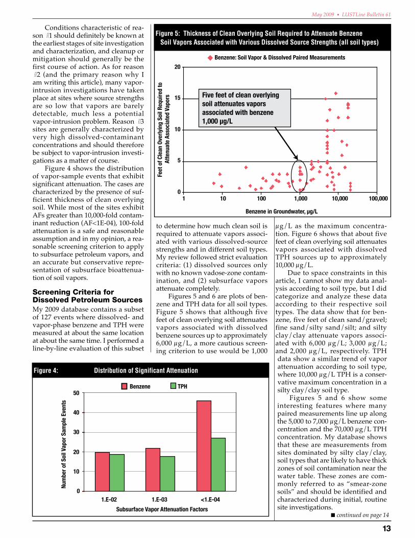
Figures 5 and 6 are plots of ben-zene and TPH data for all soil types. Figure 5 shows that although five feet of clean overlying soil attenuates vapors associated with dissolved benzene sources up to approximately 6,000 µg/L, a more cautious screen-ing criterion to use would be 1,000
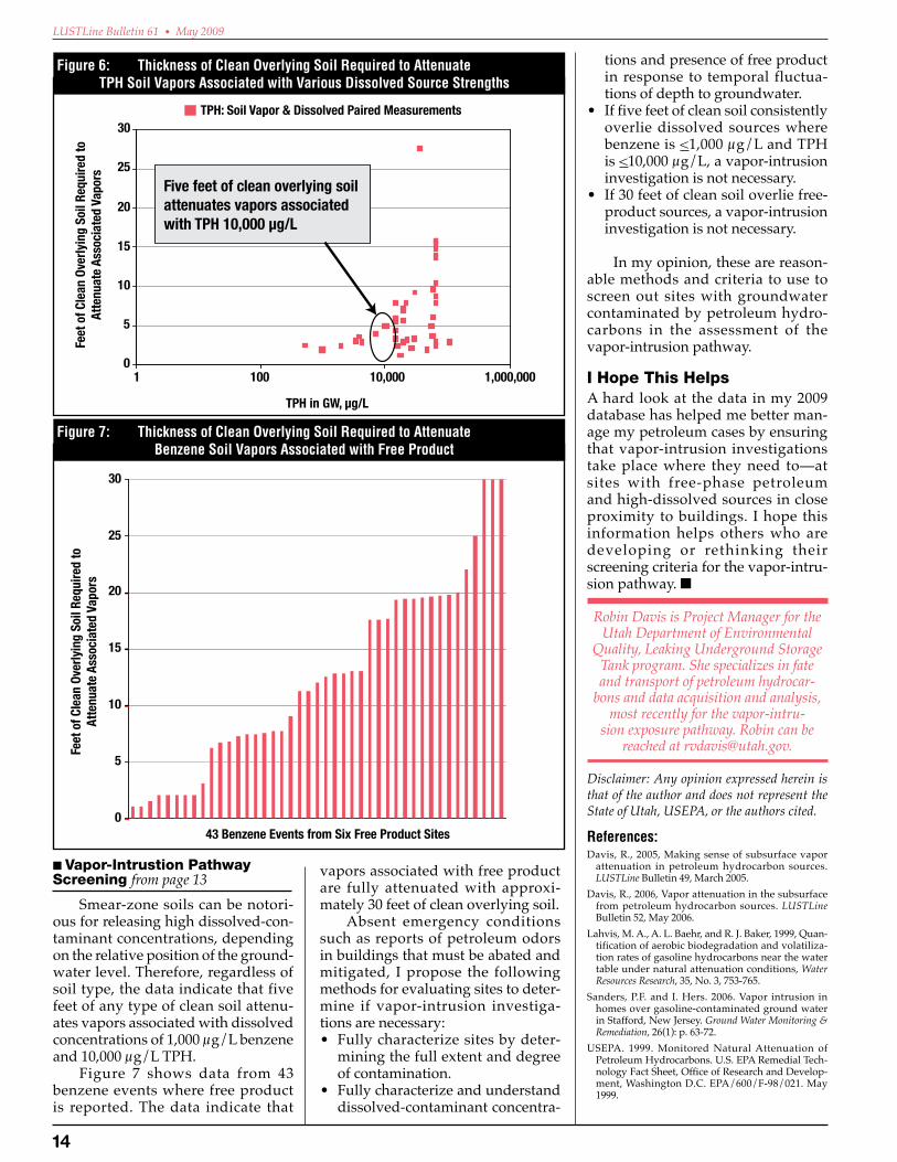
µg/L as the maximum concentra-tion. Figure 6 shows that about five feet of clean overlying soil attenuates vapors associated with dissolved TPH sources up to approximately 10,000 µg/L.
Due to space constraints in this article, I cannot show my data anal-ysis according to soil type, but I did categorize and analyze these data according to their respective soil types. The data show that for ben-zene, five feet of clean sand/gravel; fine sand/silty sand/silt; and silty clay/clay attenuate vapors associ-ated with 6,000 µg/L; 3,000 µg/L; and 2,000 µg/L, respectively. TPH data show a similar trend of vapor attenuation according to soil type, where 10,000 µg/L TPH is a conser-vative maximum concentration in a silty clay/clay soil type.
Figures 5 and 6 show some interesting features where many paired measurements line up along the 5,000 to 7,000 µg/L benzene con-centration and the 70,000 µg/L TPH concentration. My database shows that these are measurements from sites dominated by silty clay/clay, soil types that are likely to have thick zones of soil contamination near the water table. These zones are com-monly referred to as “smear-zone soils” and should be identified and characterized during initial, routine site investigations.
0
10
20
30
40
50
1.E-02 1.E-03 <1.E-04
Subsurface Vapor Attenuation Factors
Num
ber o
f Soi
l Vap
or S
ampl
e Ev
ents
Benzene TPH
Figure 4: Distribution of Significant Attenuation
0
5
10
15
20
1 10 100 1,000 10,000 100,000
Benzene in Groundwater, µg/L
Benzene: Soil Vapor & Dissolved Paired Measurements
Five feet of clean overlying soil attenuates vapors associated with benzene 1,000 µg/L
Feet
of C
lean
Ove
rlyin
g So
il Re
quire
d to
At
tenu
ate
Asso
ciat
ed V
apor
s
Figure 5: Thickness of Clean Overlying Soil Required to Attenuate Benzene Soil Vapors Associated with Various Dissolved Source Strengths (all soil types)
1�
LUSTLine Bulletin 61 • May 2009
0
5
10
15
20
25
30
1 100 10,000 1,000,000
TPH in GW, µg/L
Feet
of C
lean
Ove
rlyin
g So
il Re
quire
d to
At
tenu
ate
Asso
ciat
ed V
apor
s TPH: Soil Vapor & Dissolved Paired Measurements
Five feet of clean overlying soil attenuates vapors associated with TPH 10,000 µg/L
Figure 6: Thickness of Clean Overlying Soil Required to Attenuate TPH Soil Vapors Associated with Various Dissolved Source Strengths
Smear-zone soils can be notori-ous for releasing high dissolved-con-taminant concentrations, depending on the relative position of the ground-water level. Therefore, regardless of soil type, the data indicate that five feet of any type of clean soil attenu-ates vapors associated with dissolved concentrations of 1,000 µg/L benzene and 10,000 µg/L TPH.
Figure 7 shows data from 43 benzene events where free product is reported. The data indicate that
tions and presence of free product in response to temporal fluctua-tions of depth to groundwater.
• If five feet of clean soil consistently overlie dissolved sources where benzene is <1,000 µg/L and TPH is <10,000 µg/L, a vapor-intrusion investigation is not necessary.
• If 30 feet of clean soil overlie free-product sources, a vapor-intrusion investigation is not necessary.
In my opinion, these are reason-able methods and criteria to use to screen out sites with groundwater contaminated by petroleum hydro-carbons in the assessment of the vapor-intrusion pathway.
IHopeThisHelpsA hard look at the data in my 2009 database has helped me better man-age my petroleum cases by ensuring that vapor-intrusion investigations take place where they need to—at sites with free-phase petroleum and high-dissolved sources in close proximity to buildings. I hope this information helps others who are developing or rethinking their screening criteria for the vapor-intru-sion pathway. n
Robin Davis is Project Manager for the Utah Department of Environmental
Quality, Leaking Underground Storage Tank program. She specializes in fate and transport of petroleum hydrocar-
bons and data acquisition and analysis, most recently for the vapor-intru-
sion exposure pathway. Robin can be reached at [email protected].
Disclaimer: Any opinion expressed herein is that of the author and does not represent the State of Utah, USEPA, or the authors cited.
References:Davis, R., 2005, Making sense of subsurface vapor
attenuation in petroleum hydrocarbon sources. LUSTLine Bulletin 49, March 2005.
Davis, R., 2006, Vapor attenuation in the subsurface from petroleum hydrocarbon sources. LUSTLine Bulletin 52, May 2006.
Lahvis, M. A., A. L. Baehr, and R. J. Baker, 1999, Quan-tification of aerobic biodegradation and volatiliza-tion rates of gasoline hydrocarbons near the water table under natural attenuation conditions, Water Resources Research, 35, No. 3, 753-765.
Sanders, P.F. and I. Hers. 2006. Vapor intrusion in homes over gasoline-contaminated ground water in Stafford, New Jersey. Ground Water Monitoring & Remediation, 26(1): p. 63-72.
USEPA. 1999. Monitored Natural Attenuation of Petroleum Hydrocarbons. U.S. EPA Remedial Tech-nology Fact Sheet, Office of Research and Develop-ment, Washington D.C. EPA/600/F-98/021. May 1999.
0
5
10
15
20
25
30
43 Benzene Events from Six Free Product Sites
Feet
of C
lean
Ove
rlyin
g So
il Re
quire
d to
At
tenu
ate
Asso
ciat
ed V
apor
s
Figure 7: Thickness of Clean Overlying Soil Required to Attenuate Benzene Soil Vapors Associated with Free Product
■ Vapor-IntrustionPathwayScreeningfrom page 13 vapors associated with free product
are fully attenuated with approxi-mately 30 feet of clean overlying soil.
Absent emergency conditions such as reports of petroleum odors in buildings that must be abated and mitigated, I propose the following methods for evaluating sites to deter-mine if vapor-intrusion investiga-tions are necessary: • Fully characterize sites by deter-
mining the full extent and degree of contamination.
• Fully characterize and understand dissolved-contaminant concentra-

1�
May 2009 • LUSTLine Bulletin 61
PumpingandDispensingSystemsIn the very early years of under-ground petroleum storage, fuel was moved from the tank to the fuel dis-penser by means of a hand-operated pump located in the base of the dis-penser. Fuel was drawn out of the tank via suction, much the same way as a drink is sipped through a straw, and the pump was known as a suc-tion pump. Hand pumps were later replaced by electrically operated pumps, but the principle of opera-tion and the location of the pump at the bottom of the dispenser did not change for several decades.
Beginning in the mid-1950s a new type of pump was introduced whereby the pump mechanism was located near the bottom of the under-ground tank and thus submerged in the fuel. This type of pump pushes the fuel under a pressure of approximately 30 pounds per square inch through the piping and is variously known as a pressure pump, turbine pump, or STP (submerged turbine pump). This type of pumping system is the predominant pumping method utilized at today’s retail motor-fuel locations.
Leaks from suction-pumping systems are often self-limiting. If the piping is not tight, the prob-lem is generally noticed because air is drawn into the piping and the pump functions erratically. The advent of the submersible pump however, changed this picture dra-matically. With the pump inside the tank instead of inside the dispenser, and the piping operating under posi-tive rather than negative pressure, even large leaks in the piping did not affect the operation of the dispensing system. To this day, leaks in pressur-ized pumping systems account for the great majority of substantial sub-surface product releases.
TheFillPipeThe fill pipe is a vertical length of steel pipe, typically four inches in diameter, that is screwed into a fit-ting at the top of the tank, extend-ing upward to just below the ground surface. The top end of the pipe is fit-ted with a special adapter that mates with a special fitting that is carried on delivery trucks so delivery per-sonnel can quickly and easily clamp the delivery hose to the fill pipe.
In most of today’s gasoline USTs, a drop tube is inserted inside the fill pipe. The drop tube extends from the top of the fill pipe to within six inches or so of the bottom of the tank. Delivering fuel through a drop tube reduces the amount of vapors that are generated inside the tank, because the incoming fuel does not free-fall and splash into the product already in the tank. In addition, drop tubes accelerate the flow of fuel into the tank so that the delivery time is shortened.
In today’s storage systems, the fill pipe is surrounded by a below-grade container designed to be liq-uid tight so it can capture leaks from loose delivery fittings or any minor spills that may occur when the deliv-ery hose is detached. This container is normally covered by a lid that protects the top of the fill pipe and is designed to prevent water from entering the spill container. These spill containers have been required for nearly all oper-ating storage systems since December 1998, but they are a relatively recent addition to storage tanks, having been first introduced in the mid-1980s.
Marcel Moreau is a nationally recognized petroleum storage specialist
whose column, Tank-nically Speaking, is a regular feature of LUSTLine.
As always, we welcome your comments and questions. If there are technical issues that you would like to have Marcel discuss, let him know at [email protected].
– nically SpeakingTank – nically Speaking by Marcel Moreau
A Primer for the Next Generation of Tank People Part 2 – UST Ancillary Equipment
I n LUSTLine #60, I began a review of Tank and Piping Technology for today’s new generation of tank workers and inspectors in order to give them a sense of where we are and
how far we have come with regard to tank-related technology. This discussion may also be of interest to experienced tank folk who may have thoughts or comments they would like to share. So now, in Part 2, let’s take a look at the other ancillary stuff (pumping and dispensing systems, fill pipes, and vapor and vent piping) that is so much a part of the life and times of UST-dom.
Galvanized-pipe installation from days of yore.
■ continued on page 16

1�
LUSTLine Bulletin 61 • May 2009
Fill pipes themselves are not often a source of releases, but loose delivery fittings and the delivery process, especially the frequent dis-connection of large cumbersome delivery hoses that have been incom-pletely drained, frequently result in the spillage of small quantities of fuel. If a spill-containment manhole is not present, or if the spill-con-tainment manhole leaks, this fuel is spilled into the soil surrounding the fill pipe.
Due to miscalculations in order-ing and mistakes in delivering fuel, delivery drivers can sometimes bring too much fuel to a site. This can result in a situation where a tank is overfilled, and anywhere from a few gallons to a few hundred gallons can be spilled onto the ground. During the 1990s, overfill-prevention devices were added to motor-fuel storage systems to help reduce the frequency of these incidents, but despite these devices, overfill incidents resulting in significant releases still occur. (See “What Every Tank Owner Should Know About Overfill Prevention,” LUSTline #21, December 1994, for a detailed discussion of the workings of overfill-prevention devices.)
VaporandVentPipingIn areas of the country that suffer from air pollution, measures are taken to prevent the escape of gaso-line vapors to the atmosphere. Gaso-line vapor-control systems originated in California in the 1970s and spread to many other urban areas of the United States during the 1980s and 1990s. These measures are commonly referred to as Stage I and Stage II vapor recovery. USEPA rules enacted in January 2008 require more exten-sive use of Stage I vapor recovery to help reduce atmospheric concen-trations of hazardous air pollutants such as benzene.
StageIVaporRecoveryIn Stage I vapor recovery (Figure 1), two hoses are connected between the tank truck and the UST in order to accomplish the fuel delivery. Liq-uid gasoline flows through one hose from the truck to the underground tank, while at the same time, vapors present in the tank flow upward to
the tanker truck. The fuel in the truck and the vapors in the underground tank are simply changing places. In the absence of Stage I vapor recovery, fuel vapors present in the tank would be exhausted through the vent pipe into the atmosphere as the fuel enters the UST.
There are two types of Stage I vapor recovery. The type illustrated in Figure 1 is called “two-point” because it uses two separate connec-
Figure 1: Diagram of Stage I Two-Point Vapor Recovery
Figure 2: Diagram of Coaxial Stage I Vapor Recovery
■ Tank-nicallySpeakingfrom page 15
tions to the underground tank, one for fuel and one for vapor. The other type is called “coaxial” Stage I vapor recovery (see Figure 2). The coaxial system modifies the fill pipe so that fuel can enter and vapors can exit from the same tank opening. This is usually accomplished by installing a 3-inch diameter drop tube inside the 4-inch fill pipe, creating a gap between the drop tube and the fill riser through which vapors can pass. The delivery driver uses a special fit-ting to connect to the tank fill pipe that allows the fluid-delivery hose from the truck to connect to the drop tube while the vapor-recovery hose from the truck connects to the space between the drop tube and the fill pipe.
StageIIVaporRecoveryIn Stage II vapor recovery (Figure 3), vapors are transferred from a vehi-cle fuel tank into the UST when fuel is dispensed into the vehicle. This requires the installation of vapor pip-ing from the dispensing nozzle all the way back to the UST. This vapor piping generally consists of a special nozzle that includes a vapor path as well as a fuel path, a vapor-car-rying hose between the nozzle and the dispenser, vapor piping within the dispenser, and a separate, below-ground vapor-piping run between the dispenser and the tanks.
There are two main types of Stage II vapor-recovery systems: bal-ance and vacuum assist.

1�
May 2009 • LUSTLine Bulletin 61
• Balancevapor-recoverysystems have been in use since the 1970s. In the balance system, no motors or pumps are used to move the gasoline vapors from the automo-bile tank to the underground tank. Instead, a bellows-type device surrounds the nozzle spout and creates an airtight seal around the automobile fill pipe. As fuel enters the vehicle tank, vapors in the tank are forced out and flow through the bellows, the nozzle, and the vapor piping to reach the UST.
• Vacuum-assist vapor-recoverysystems did not come into com-mon use until the mid-1990s. In the vacuum-assist type of Stage II vapor recovery, a special vapor pump, typically located inside the dispenser cabinet, pumps the gas-oline vapors out of the vehicle gas tank and into the UST. Nozzles used with vacuum-assist systems do not have a bellows and look very much like a conventional gas-oline-dispensing nozzle. Because vacuum-assist systems forcibly push vapors into the UST, they can build up slight pressures inside the tank if the volume of vapors returned to the tank is greater than the volume of liquid gasoline
removed from the tank.
The meth-o d o l o g y f o r capturing gas-ol ine vapors generated dur-i n g v e h i c l e fueling is pres-ently in a tran-sit ion phase. Stage II vapor r e c o v e r y i s being replaced b y o n b o a r d refueling va-por recovery (ORVR). Rather than capturing gasoline vapors at the fuel inlet of the vehicle and bringing them to the underground storage tank, ORVR uses a carbon canis-ter to capture the vapors as
they leave the vehicle gas tank and retain them in the vehicle. Vehicles equipped with onboard canisters were first produced in the 1998 model year in the United States. Since 2006, all cars as well as light and medium duty trucks sold in the United States have been equipped for ORVR. Federal regulations state that once ORVR is in “widespread use” Stage II vapor recovery will no longer be required.
The USEPA has been tasked with determining when ORVR will be in “widespread use.” Once this deter-mination has been made, state and local air quality control agencies may permit gasoline-dispensing facili-ties to discontinue the use of Stage II vapor-recovery systems.
VentPipesUnderground tanks are not designed to withstand any great pressure or vacuum; they must constantly remain at or near normal atmospheric pres-sure. To ensure that underground tanks can “breathe” as fuel is added or removed, they are equipped with vent pipes that connect the inside of the tank to the atmosphere. The vent pipe is connected to the top of
Figure 3: Diagram of Stage II Vapor Recoverythe UST and typically runs below the ground surface to an out-of-the-way location where it can be brought above ground.
Most aboveground portions of vent pipes are constructed of galva-nized steel pipe and extend 12 feet or more above the ground surface. Vent piping belowground is usually constructed of fiberglass, though it may be constructed of galvanized steel. Galvanized steel is acceptable for vent piping because it does not routinely contain liquid product and so is not subject to the federal regula-tions regarding corrosion protection or leak detection.
Vent piping must slope uni-formly back to the tank so that any liquid that enters the vent piping does not get trapped in any low spots. Flexible piping is difficult to install with a uniform slope and is not often used for below-grade vent piping. Most aboveground portions of vent pipes are constructed of gal-vanized steel and extend 12 feet or more above the ground surface.
When fuel is added to the tank, vapors inside the tank are either expelled through the vent pipe into the atmosphere, or, if Stage I vapor recovery is present, returned to the tank truck. When fuel is removed from the tank, ambient air can enter the tank via the vent pipe to prevent the creation of a vacuum in the tank. Alternatively, if Stage II vapor recov-ery is present, vapors removed from the automobile gas tank are returned to the underground tank, and there is little or no need for air to flow into the tank from the vent pipe.
To further contain vapors in the UST, vent pipes associated with tanks where vapor recovery is installed are often fitted with special caps that seal the vent-pipe opening. These vent caps will only open when there is a small pressure imbalance between the tank and the atmosphere that causes the vent cap to open to relieve the pressure or vacuum inside the storage tank.
Comments?Well, that ends my very short course on tanks, piping, and other ancillary UST stuff. If you have any historical footnotes or anecdotes you would like to add, please send me an e-mail at [email protected]. n

1�
LUSTLine Bulletin 61 • May 2009
The LUSTLine #58 cover story in September 2008 asked if groundwater will ever get some respect and talked about why underground storage tanks matter. Someone took
the message in that cover story to heart, because the American Recovery and Reinvestment Act of 2009 gave the underground storage tank (UST) program a whole lot of respect, in the form of $200 million to assess and clean up UST-system leaks.
In reporting to USEPA for the National Water Quality Inventory 2000 Report (EPA-841-R-02-001; August 2002), states, territories, and tribes said that petroleum released from UST systems is one of the leading threats to our country’s groundwater. Because groundwater supplies drinking water for about half of the nation’s overall population and 99 percent of the population in rural areas, the health of our groundwater is extremely important. The $200 million Recovery Act money to assess and clean up leaking underground storage tanks (LUSTs) reinforces the value of groundwater to our country.
This one-time infusion of money, which is approximately three times the amount of LUST money the national UST pro-gram typically receives each year, shows an acknowledgment that USTs continue to affect our nation’s groundwater. It also shows recognition of the role tank work plays in the economy; people will be put to work assessing and cleaning up releases from UST systems. This is a boost to our environment and our economy.
Although the LUST Recovery Act money is a welcome addition to the national UST program, it comes with unprece-dented requirements for transparency, oversight, and account-ability to help ensure that taxpayer dollars are spent wisely and that Americans will see results for their investments. Even though USEPA, as well as state and territorial UST programs, will be carefully reporting on how and where we are spending LUST Recovery Act money, I believe these additional manage-ment efforts are well worth it because we will be documenting that:
• LUST sites have been cleaned up, • thousands of jobs were created or retained, and • our soil and groundwater have greatly benefitted.
How USEPA Divided $200 Million USEPA’s Office of Underground Storage Tanks (OUST) worked with USEPA regional tank program managers to strategically plan how to best distribute the LUST Recovery Act money. Keeping in mind that state and territorial tank programs are primarily responsible for implementing the UST program, we devised the following distribution plan:
• $190.7 million to all states and territories (except North Dakota and American Samoa who declined LUST Recovery Act money) in the form of coopera-tive agreements to address shovel-ready sites within their jurisdictions. We used the existing LUST Trust Fund allocation formula to divide the $190.7 million among the 54 states and territories receiving LUST Recovery Act money. In spring 2009, USEPA regional UST programs will enter into cooperative agreements with their states and territories. These cooperative agreements will include more detailed descriptions of states’ spending plans.
• $6.3 million managed by USEPA regional tank pro-grams using existing USEPA in-house contracts to do LUST-eligible work (e.g., site assessment and cleanup activities) in Indian country.
• $3 million retained by USEPA, shared by headquarters and regions, to manage, oversee, and report on appro-priate spending of the $197 million going to states and territories and for cleanups in Indian country.
What’s Next? Before entering into cooperative agreements with states and territories, USEPA regional UST programs need to receive guidance on the terms and conditions that apply to the LUST Recovery Act money. With that in mind, USEPA-OUST developed LUST Recovery Act program guidance, which will assist USEPA regions in negotiating and approving state and territorial cooperative agreements. In early June, USEPA-OUST will be able to share the final program guidance with USEPA regional UST programs so they can enter into coop-erative agreements with their states and territories.
We are on the cusp of summer, with months of con-struction-friendly weather ahead, so the timing of the LUST Recovery Act money is ideal. States and territories will be able to use LUST Recovery Act money to assess and clean up UST leaks, which will protect our land and groundwater as well as help create jobs. Now that’s a whole lot of R-E-S-P-E-C-T.
For more about LUST Recovery Act money, see www.epa.gov/oust/eparecovery. n
AMESSAGEFROMCAROLYNHOSkINSONActing Director, USEPA’s Office of Underground Storage Tanks
U-S-T-sGetSomeR - E - S - P - E - C - T intheRecoveryAct

1�
May 2009 • LUSTLine Bulletin 61
FindingOutdatedEquipmentontheNWGLDEList
FAQsfromtheNWGLDE…All you ever wanted to know about leak detection, but were afraid to ask.
In this FAQs from the National Work Group on Leak Detection Evaluations (NWGLDE) we discuss cross-referencing leak-detection equipment and systems that have been sold to a different vendor or rebranded. (Please note: the views expressed in this column represent those of the work group and not necessarily those of any implementing agency.)
Q.DoestheNWGLDEtrackvendorequipmentinfor-mationontheListofLeakDetectionEvaluationsforStorageTankSystems(theList)afteritissoldortransferredtoadifferentvendor?
A. Yes. Since 2002 over 25 percent of the equipment ref-erenced in the List has been sold or rebranded. (See NWGLDE.org.) Because of the high turnover per-centage, and at the request of the vendors involved, the work group does track this information. Vendors need to be aware that when leak-detection equipment or systems have been sold or transferred, the work group requires a letter from both the former and the new vendors confirming the sale in order to update the vendor information.
Q.HowmightaninspectorfindequipmentontheListifonlyoutdatedvendorinformationisavailableatthetimeofanUSTinspection?
A. The individual equipment-listing data sheets always display the current vendor information in the lower left corner along with a revision date in the upper left corner. In addition to the current vendor information, the List cross-references vendors in the “Vendor by Alpha” indices pages.
Former vendors continue to be listed with cross-ref-erenced links to the new vendor(s) and equipment. Current vendors that have made simple name-only changes reference the original vendor in parentheses (e.g., see Coggins Systems, Inc. whose equipment is now listed under Varec, Inc.). For larger acquisitions, each acquisition and its associated equipment are listed under the vendor that acquired the equipment
from a previous vendor (e.g., see OPW or Veeder-Root).
Once equipment is listed under a vendor or brand name, that vendor or brand name is forever on the “Vendor by Alpha” list. No matter what name you use to look up something (if it was a valid name at any point in time), you will find this name in the Alpha List, but you may be redirected to the current vendor or brand name to find the actual listing.
If all else fails, the website search engine, located at the top right corner of the work group home page, can always be used to find specific leak-detection equipment and/or vendor information.
AbouttheNWGLDEThe NWGLDE is an independent work group comprising ten members, including nine state and one USEPA member. This column provides answers to frequently asked questions (FAQs) the NWGLDE receives from regulators and people in the industry on leak detection. If you have questions for the group, please contact NWGLDE at [email protected].
NWGLDE’sMission:■ Review leak-detection system evaluations to determine if each
evaluation was performed in accordance with an acceptable leak-detection test method protocol and ensure that the leak-detection system meets USEPA and/or other applicable regulatory perfor-mance standards.
■ Review only draft and final leak-detection test-method protocols submitted to the work group by a peer review committee to ensure they meet equivalency standards stated in the USEPA standard test procedures.
■ Make the results of such reviews available to interested parties.
L.U.S.T.LINE Subscription FormName________________________________________________________________________________________________________________________
Company/Agency ____________________________________________________________________________________________________________
MailingAddress______________________________________________________________________________________________________________
E-mailAddress_______________________________________________________________________________________________________________
❏ One-yearsubscription: $18.00.
❏ Federal,state,orlocalgovernment: Exempt from fee. (For home delivery, include request on agency letterhead.)
Please enclose a check or money order (drawn on a U.S. bank) made payable to NEIWPCC.
Send to: NewEnglandInterstateWaterPollutionControlCommission116 John Street, Lowell, MA 01852-1124Phone: (978) 323-7929 ■ Fax: (978) 323-7919 ■ [email protected] ■ www.neiwpcc.org
The NEW version of the LUSTLine Index is ONLy available online. To download the LUSTLine Index, go to http://www.neiwpcc.org/lustline/ and then click on LUSTLine Index
L.U.S.T.LINE INDEXAugust 1985/Bulletin #1 – May 2009/Bulletin #61

When evaluating storage tank insurance coverage, tank owners should exam-
ine their quotes, including the sam-ple policy form and all endorsements that will be included with the pro-posed coverage, as these may further restrict coverage by modifying the definition of a covered storage tank, or tanks used for specific purposes in certain stages of use. Examples of this include the “Marina Exclusion Endorsement” and the “Out of Ser-vice” exclusionary endorsement.
MarinaExclusion: This insurance does not apply to
claims caused by a release from a storage-tank system at a covered facility from any piping, dispens-ers, or nozzles located over any body of water.
Out-of-ServiceTank It is hereby agreed that the Stor-
age Tank Policy Form, Section III. Exclusions, has been amended to include the following: The term Out of Service means any under-
ground storage tank that is no longer used for the dispensing of petroleum or regulated sub-stances.
Although the policy definition of a “covered storage tank” may include all piping and ancillary equip-ment attached thereto, if the policy includes a marina exclusion endorse-ment, losses caused by releases from the lines/dispensers over any body of water would not be eligible for coverage.
Similarly, with the Out-of-Ser-vice exclusion, if any “covered stor-age tank” is temporarily closed or taken “out of service” for mainte-nance, repair, or upgrade, coverage immediately ceases and does not continue until that tank is put back into service. So, any contamination discovered in the course of the main-tenance or upgrade is not covered by the policy.
While some policies may provide coverage for tanks being taken out of service, they may also contain spe-cific notification requirements that
UST Insurance Matters……Endorsed Insurance Coverageby Chris Montgomery
must be met to trigger coverage. For example, certain policies require that the tank owner/operator notify the insurance company of their intention to remove or replace underground storage tank(s), lest coverage will not be provided. One policy contains this language: Notice of Voluntary Scheduled
StorageTankSystemRemovalorReplacement- You (the insured) shall provide notice to us (the insurance company) of your inten-tion to perform a voluntary, sched-uled storage-tank system removal or replacement at least 48 hours prior to the voluntary scheduled storage-tank system removal or replacement. Notice shall be pro-vided consistent with CLAIM PROVISIONS, Notice of Potential Claim.
A knowledgeable insurance agent or broker who is familiar with “the fine print” in storage tank poli-cies can help owners, operators, and regulators understand what each policy covers and, more importantly, does not cover. n
Chris Montgomery is a principal with Custom Environmental Insurance.
He can be reached at 877-TANKCOV (826-5268) or [email protected].
L.U.S.T.LINENewEnglandInterstateWaterPollutionControlCommission116JohnStreetLowell,MA01852-1124
Non-Profit Org.U.S. Postage
PAIDWilmington, MA
Permit No.200
Presentations from the
2009 National Tanks Conference
are available online!
Visit the conference website at
www.neiwpcc.org/tanksconference
and select the “Archives” tab.
This will bring you to our Tanks
Conference Archives page where
you will find instructions on how
to access presentations.