lumireview280103.ppt p. denes p. 1 luminosity monitor review concept instrument tan (tas), count n...
TRANSCRIPT

LumiReview280103.pptP. Denes p. 1
Luminosity Monitor Review
Luminosity Monitor Review
• ConceptInstrument TAN (TAS), count n
• RequirementsImplications of the requirements on the design ofthe luminosity monitor
• New MechanicsUpdated design for inert gas ionization chamberSuggestions/Compatibility with solid state detector
• Electronics• Previous test beam results and current test beam needs
Bill Turner, who would normally be presenting much ofthis, can not be here today, so we are filling in (at timesperhaps imperfectly)

LumiReview280103.pptP. Denes p. 2
Luminosity Monitor Concept
Luminosity Monitor Concept
D1 triplet TAS TAS triplet D1
TANTAN
IP140 m140 m
nL R
• Luminosity NMIP from n shower• Crossing Angle L+R
Instrument TAN
Massimo

LumiReview280103.pptP. Denes p. 3
TAN
TAN
IP
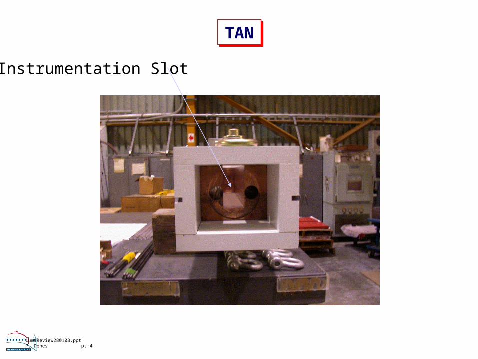
Instrument a Copper Bar
LumiReview280103.pptP. Denes p. 4
TAN
TAN
Instrumentation Slot

LumiReview280103.pptP. Denes p. 5
Detector Constraints - I.
Detector Constraints - I.
Charged particles swept away(Gas) Detector placed after several INT (few )m ~1 n per 3 pp interactions (in the acceptance)
Offset due to ±150 µrad crossing angle
• Horizontal, vertical or 45° crossing• ~ 80 x 80 mm2 for detector• Segment (for position)
Table 3 : Geometry of the interacting beams
Xing plane Range of
half Xing angle
Baseline 2002 Option
degree degree rad
IP1 90 45 90 90 [0175]
IP2 90 [0150]
IP5 0 45 0 90 [0175]
IP8 0 [0285]
LHC Project Document No.
LHC-B-ES-0004 rev 2.0

LumiReview280103.pptP. Denes p. 6
Detector Constraints - II.
Detector Constraints - II.
• Signal collection time < 25 ns• Modest S/N performance:
Shower fluctuations (NMIP)/NMIP ~ 30%
<npp> 1
P = 1% needs N~3000 pp interactions
2
2
31
)(
PN
⎟⎠⎞⎜
⎝⎛
≥N
Nσ
Desired precisionNumber of eventsn / pp interaction

LumiReview280103.pptP. Denes p. 7
Detector Constraints - III.
Detector Constraints - III.
0
1
2
3
4
5
6
7
8
9
10
1 10 100
Signal-to-Noise Ratio
N(with noise)/N(no noise)
Given large hadronic shower fluctuations,SNR ~ 4 or 5 is sufficient
Effect of SNRon N to achieve P

LumiReview280103.pptP. Denes p. 8
Requirements
Requirements
LBNL25 Jan. 2002
40 MHz Ionization ChamberW.C. Turner
11
Requirements (Lumi mini Workshop, 16-17 Apr. 99)
• Absolute L measurement with L/ ~ 5% > 10L for L 30 cm-2sec-1
• Cross calibration with LHC experiment measurements of L( )every few months
• Sensitivity of L measurement to variations of IP position( *, *<1 ) ( *x y mm and crossing angle x’,y* ’<10μrad) less than 1%
• Dynamic range with “reasonable” acquisition times for 1% precision to cover 10 28cm-2 sec-1 to 10 34cm-2 sec-1
• Capable of use to keep machine tuned within ~ 2% of optimum L
• Bandwidth 40 MHz to resolve the luminosity of individual bunches
• Backgrounds less than 10% of the L signal and correctable
Update
Update

LumiReview280103.pptP. Denes p. 9
Requirements
Requirements
Total LAbsolute L from experimentsL/L ~ 1%Reproducibility ~ 1%Integration time ~ 1s
Bunch-by-bunch
(most stringent: )
L/L ~ 1%Integration time ~ minutes
⎟⎠⎞
⎜⎝⎛−
∝2*
2
2
0
σD
eLL
And bringing beams into collision

LumiReview280103.pptP. Denes p. 10
Total Luminosity
Total Luminosity
m=0.33 INEL=80 mb SNR=5

LumiReview280103.pptP. Denes p. 11
Bunch-by-bunch Luminosity
Bunch-by-bunch Luminosity
m=0.33 INEL=80 mb SNR=5 2808 bunches
LumiReview280103.pptP. Denes p. 12
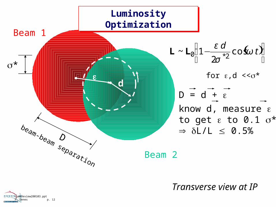
Luminosity OptimizationLuminosity
Optimization
Transverse view at IP
Beam 1
*
Dbeam-beam separation
Beam 2
d
( )⎟⎠
⎞⎜⎝
⎛ − td
ωσ
εcos
21~
2*0LL
for ,d <<*
D = d + know d, measure to get to 0.1 * L/L 0.5%

LumiReview280103.pptP. Denes p. 13
Current Design Options
Current Design Options
Ionization Chamber
Gas Solid
Active mediumRadiation Hardness
Mechanical stability
SpeedNoise (SNR)
Ar + N
medium replaceable
fixed components low mobility doable
CdTe
hardness to be shown
depends on contacting higher mobility trivial
Very high TID - up to ~250 000 MRad/10 yrs
Access as infrequently as possible
LumiReview280103.pptP. Denes p. 14
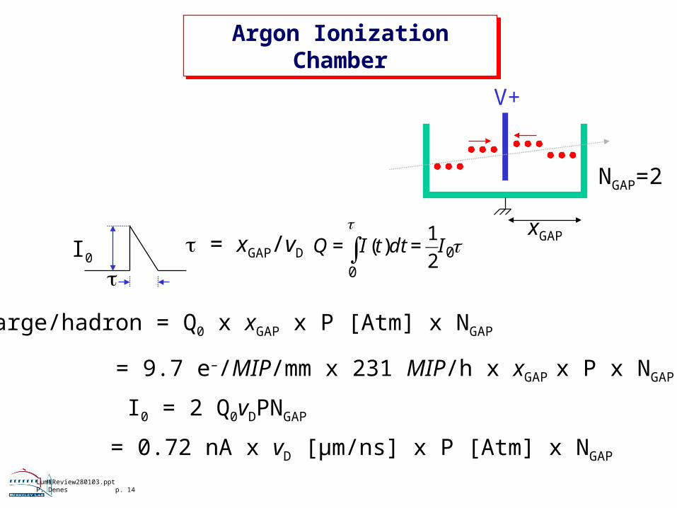
Argon Ionization Chamber
Argon Ionization Chamber
I0
= xGAP/vD
charge/hadron = Q0 x xGAP x P [Atm] x NGAP
00
2
1)( IdttIQ ∫ ==
I0 = 2 Q0vDPNGAP
= 9.7 e–/MIP/mm x 231 MIP/h x xGAP x P x NGAP
= 0.72 nA x vD [µm/ns] x P [Atm] x NGAP
V+
xGAP
NGAP=2
LumiReview280103.pptP. Denes p. 15
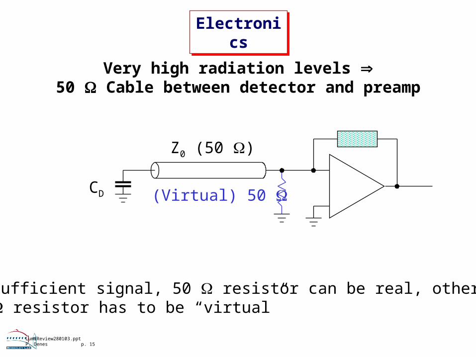
Electronics
Electronics
Very high radiation levels 50 Cable between detector and preamp
CD
Z0 (50 )
(Virtual) 50
If sufficient signal, 50 resistor can be real, otherwise50 resistor has to be “virtual”

LumiReview280103.pptP. Denes p. 16
Modified Ionization Chamber Design
Modified Ionization Chamber Design
Area constrained:4 quadrants A ~ 4x4 cm2
Capacitance per gapCGAP = A/xGAP
• Gap dimensions• Gap topology• Number of gaps• Gas properties
Update of previous mechanical designGoal: simplified construction higher reliability
• Consider all configurations which fit into Cu bar volume• Consider different gases / mixtures (simulation)

LumiReview280103.pptP. Denes p. 17
Optimizing the layout
Optimizing the layout
Coax cableNGAP
xGAP
“50”
IonizationCurrent
I0
T
TimeConstant
50 x CDETECTOR
LumiReview280103.pptP. Denes p. 18
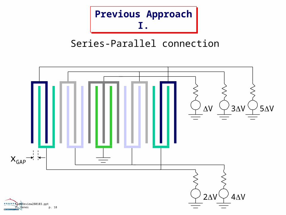
Previous Approach I.Previous
Approach I.
Series-Parallel connection
xGAP
V 3V 5V
2V 4V

LumiReview280103.pptP. Denes p. 19
Previous Approach II.
Previous Approach II.
NGAP = NSER x NPAR
Effective gas volume = xGAP x NPAR
CDETECTOR = CGAP x NPAR / NSER
Parasitics - Hard to achieve CDETECTOR, complex mechanics
NGAP = 60xGAP = 0.5mmNPAR = 10, L = 5mmNSER = 6

LumiReview280103.pptP. Denes p. 20
Improved Speed Possible
Improved Speed Possible
0
10
20
30
40
50
60
80 85 90 95 100
Ar [%] in Ar+N2
v [micron/ns] at 3kV/cm 1 Atm
Previous Operating Point
simulated with MAGBOLTZ

LumiReview280103.pptP. Denes p. 21
Drift Velocity
Drift Velocity
0 500 1000 15000
1
2
3
4
Vel
ocity
(cm
/mic
rose
c)
E(V/cm-atm)
Ar+1%N2
Ar+1.5%N2
Ar+2%N2
Ar+3%N2
Simulation
Measured
Data vs. Simulation
Ar (98%) N2 (2%)Ar (97%) N2 (3%)Ar (96%) N2 (4%)

LumiReview280103.pptP. Denes p. 22
Example: Constant 6 mm Gas Volume
Current Waveform into Preamplifier
Example: Constant 6 mm Gas Volume
Current Waveform into Preamplifier
0.00
0.02
0.04
0.06
0.08
0.10
0.12
0.14
000E+0 25E-9 50E-9 75E-9 100E-9
Time [s]
2 gaps3 gaps4 gaps5 gaps6 gaps
Cu
rren
t [µ
A]
at
1 A
tm A
r/N
2 (
96::
4)
LumiReview280103.pptP. Denes p. 23
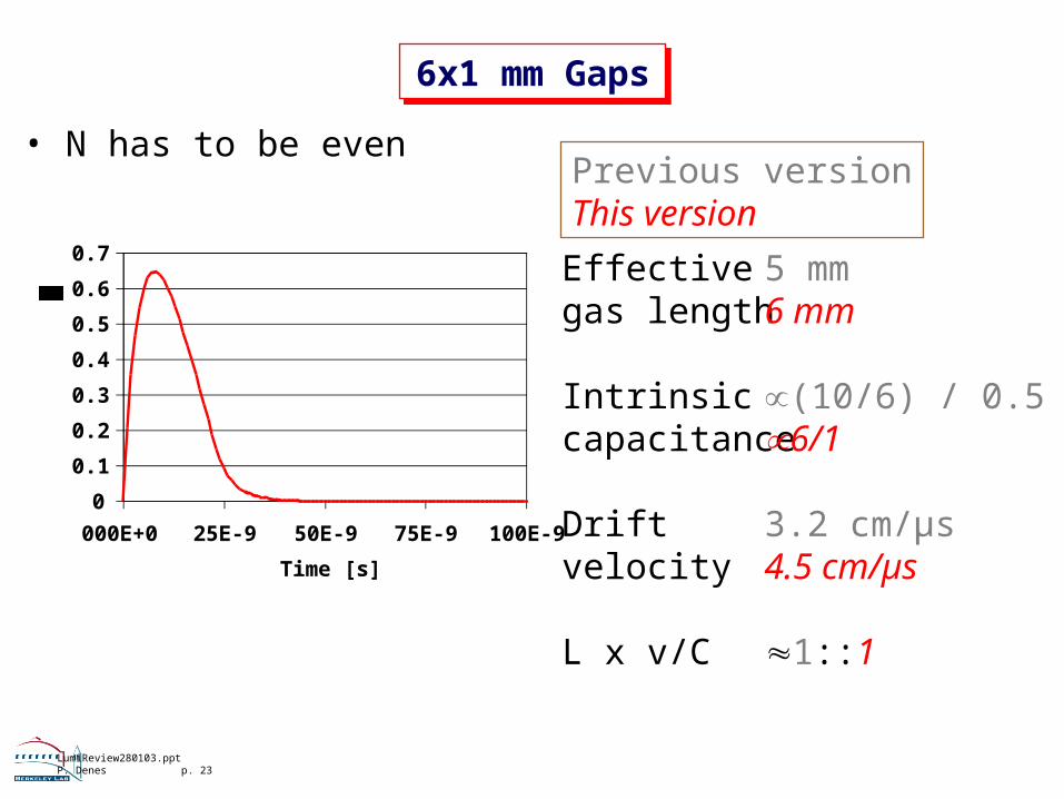
6x1 mm Gaps
6x1 mm Gaps
• N has to be even
0
0.1
0.2
0.3
0.4
0.5
0.6
0.7
000E+0 25E-9 50E-9 75E-9 100E-9
Time [s]
Current at 1 Atm [
A] Effectivegas length
Intrinsiccapacitance
Driftvelocity
L x v/C
5 mm6 mm
(10/6) / 0.56/1
3.2 cm/µs4.5 cm/µs
1::1
Previous versionThis version

LumiReview280103.pptP. Denes p. 24
Detector ConceptDetector Concept
• One ground “comb” milled from a solid Cu block• Four signal “combs”• Ceramic insulation/alignment pieces (machineable MACOR)
Detector mechanical design: T. Loew, D. ChengVessel mechanical design: M. HoffFabrication design: N. Salmon, A. Mei

LumiReview280103.pptP. Denes p. 25
Assembly I.
Assembly I.
Signal comb
Alignment features(explained below)

LumiReview280103.pptP. Denes p. 26
Assembly II.
Assembly II.
Ground planes
2 mm Cu / 1 mm gap (i.e. 4 mm between plates)40 mm depth < 10::1 aspect ratio - OK for machining
Solid groundseparates all4 quadrants

LumiReview280103.pptP. Denes p. 27
Assembly III.
Assembly III.
Alignment features

LumiReview280103.pptP. Denes p. 28
Assembly IV.
Assembly IV.
One ceramic face ismetallized for bias filterand connections to rad-hard coax cable
SignalHV
LumiReview280103.pptP. Denes p. 29
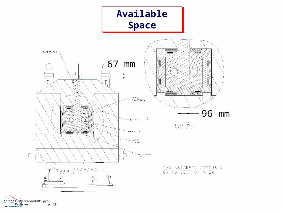
Available Space
Available Space
96 mm
67 mm

LumiReview280103.pptP. Denes p. 30
Quadrant DimensionsQuadrant
Dimensions
Not to scale
94
CeramicStainlessSteel
38
40
Copper
0.5
2.5
3.54.0
LumiReview280103.pptP. Denes p. 31
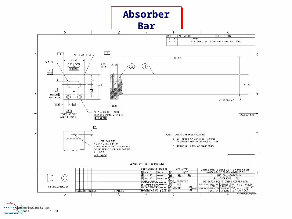
Absorber Bar
Absorber Bar
LumiReview280103.pptP. Denes p. 32
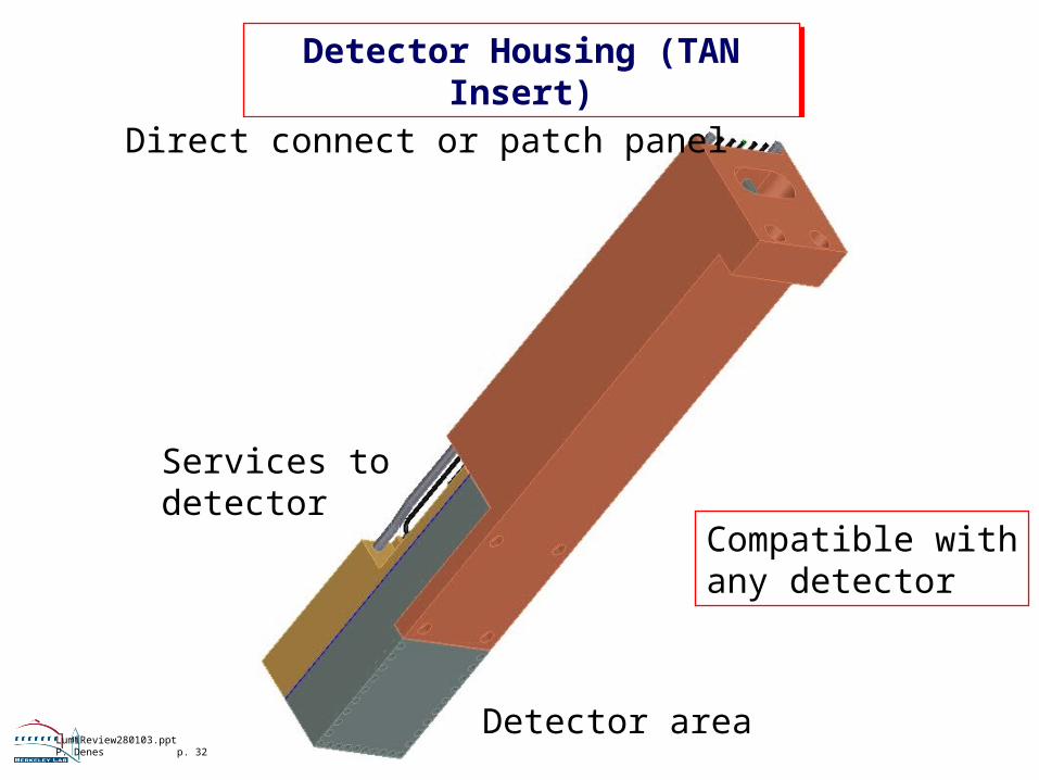
Detector Housing (TAN Insert)
Detector Housing (TAN Insert)
Detector area
Services todetector
Direct connect or patch panel
Compatible withany detector

LumiReview280103.pptP. Denes p. 33
Detector HousingDetector Housing
Signal+HVConnectors
Gas
Met
al p
ress
ure
seal
DetectorVolume
DetectorVolume
Gas

LumiReview280103.pptP. Denes p. 34
Constraints - I.
Constraints - I.
Thin wall dimensiondesigned so thatvessel withstands15 Atm.
LumiReview280103.pptP. Denes p. 35
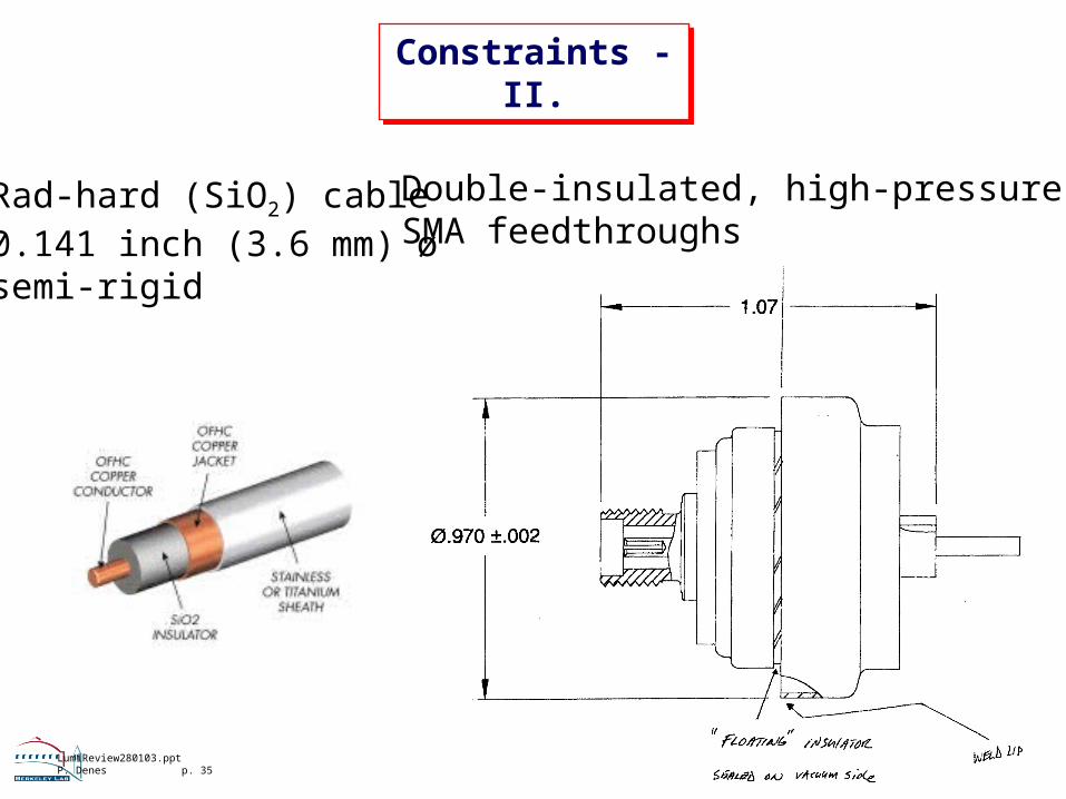
Constraints - II.
Constraints - II.
Double-insulated, high-pressureSMA feedthroughs
Rad-hard (SiO2) cable0.141 inch (3.6 mm) øsemi-rigid

LumiReview280103.pptP. Denes p. 36
Complete Insert
Complete Insert
• Insulated from TAN by 0.5 mm ceramic• Rad-hard semi-rigid coax insulated by ceramic beads from housing• Compatible with standard lifting mechanism

LumiReview280103.pptP. Denes p. 37
Detector Mounted in Vessel
Detector Mounted in Vessel

LumiReview280103.pptP. Denes p. 38
Integration
Integration

LumiReview280103.pptP. Denes p. 39
Engineering Solution in Preparation
Engineering Solution in Preparation

LumiReview280103.pptP. Denes p. 40
CdTe
CdTe
LumiReview280103.pptP. Denes p. 41
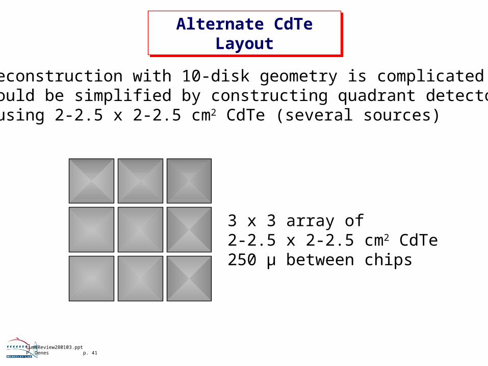
Alternate CdTe Layout
Alternate CdTe Layout
• Reconstruction with 10-disk geometry is complicated• Could be simplified by constructing quadrant detector using 2-2.5 x 2-2.5 cm2 CdTe (several sources)
3 x 3 array of2-2.5 x 2-2.5 cm2 CdTe250 µ between chips

LumiReview280103.pptP. Denes p. 42
CdTe Assembly Using Spring Contacts
CdTe Assembly Using Spring Contacts

LumiReview280103.pptP. Denes p. 43
Detector Housing (TAN Insert)
Detector Housing (TAN Insert)
Same idea, but morecables (and no gas lines)

LumiReview280103.pptP. Denes p. 44
Assembly
Assembly

LumiReview280103.pptP. Denes p. 45
0
10
20
30
40
50
000E+0 25E-9 50E-9
Time [s]
Current into Preamp [
A]
Current Pulse from 2 x 2 cm2 CdTe
Current Pulse from 2 x 2 cm2 CdTe
into 50, 93 pF7 ke-/MIP, 280 MIP

LumiReview280103.pptP. Denes p. 46
CdTe vs. Ar+N2
CdTe vs. Ar+N2
CdTe - radiation-induced leakage current CdTe - Leakage current ~ T2 eT
CdTe - complicated reconstruction - can be solved with different mechanics
CdTe - Faster than Ar+N2, deconvolution required
Ar+N2 - Active medium “easy to replace”
Ar+N2 - Signal smaller than CdTe (less important - have to average over many pulses due to shower fluctuations)
Franco

LumiReview280103.pptP. Denes p. 47
Simulation
Simulation
50% of signalper quadrant
6x1 mm gaps6 ATM Ar (96%) N2 (4%)4 cm/µs drift velocityI0 = 1 µA
I0

LumiReview280103.pptP. Denes p. 48
Pulse SpeedPulse Speed
A return to baseline within 25 ns is not necessary if• Noise is uncorrelated
Averaging over many samples is required in orderto smooth out shower fluctuations
• The pulse shape is linear over the dynamic rangeNot only linearity at the peak, but also invarianceof the shape with amplitude are required
In this case, deconvolution is straight-forward
LumiReview280103.pptP. Denes p. 49
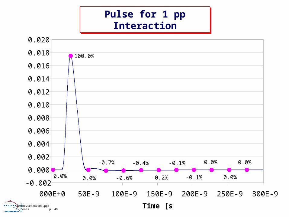
Pulse for 1 pp Interaction
Pulse for 1 pp Interaction
100.0%
0.0%
0.0%
0.0%
-0.1%
-0.1%
-0.2%
-0.4%
-0.6%
-0.7%
0.0%0.0%-0.002
0.000
0.002
0.004
0.006
0.008
0.010
0.012
0.014
0.016
0.018
0.020
000E+0 50E-9 100E-9 150E-9 200E-9 250E-9 300E-9
Time [s]
Amplitude [V]

LumiReview280103.pptP. Denes p. 50
Deconvolution - I.
Deconvolution - I.
∑∞
−∞=−=
kkiki QaV
⎥⎥⎦
⎤
⎢⎢⎣
⎡−= ∑
=−
k
jjkjkk QaV
aQ
10
1
-0.05
0.00
0.05
0.10
0.15
0.20
0.25
0.30
0.35
0.40
000E+0 50E-9 100E-9 150E-9 200E-9 250E-9 300E-9
Time [s]
Amplitude [V]

LumiReview280103.pptP. Denes p. 51
Deconvolution - II.
Deconvolution - II.
-0.050
0.000
0.050
0.100
0.150
0.200
0.250
0.300
0.350
0.400
000E+0 50E-9 100E-9 150E-9 200E-9 250E-9 300E-9
Time [s]
Amplitude [V]
t V Q2E-9 0.000 0.0
27E-9 0.349 19.952E-9 0.349 19.977E-9 0.347 19.9
102E-9 0.017 1.2127E-9 0.340 19.8152E-9 -0.001 0.2177E-9 -0.006 0.0202E-9 -0.004 0.0227E-9 -0.002 0.0252E-9 -0.001 0.0277E-9 -0.001 0.0
A 1% error (linearity, mis-termination, ...) results in a 20% error on a 1 interaction pulse preceded by a 20 interaction pulse

LumiReview280103.pptP. Denes p. 52
Pulse Shape Uniformity
Pulse Shape Uniformity
A variation of pulse shape would mean that a1/a0
is not constantPerfectly Linear
20.02
1.00 0.021.450.00
5.00
10.00
15.00
20.00
25.00
-20E-9 000E+0 20E-9 40E-9 60E-9 80E-9 100E-9
Time [s]
Amplitude
t [ns] V(i) Q(i) N(i)8 1.0000 1.0000 1.00
33 20.022520.000020.0058 1.4498 0.9991 1.0083 0.0237-0.0190-0.02

LumiReview280103.pptP. Denes p. 53
Example - 5% Shape Non-Uniformity
Example - 5% Shape Non-Uniformity
0.0225
1
0.02140.0
0.2
0.4
0.6
0.8
1.0
1.2
000E+0 10E-9 20E-9 30E-9 40E-9 50E-9
Time [ns]
Amplitude
a1/a0 differs by5% in the 2 curves

LumiReview280103.pptP. Denes p. 54
5% Shape Non-Uniformity
5% Shape Non-Uniformity
20.02
1.00 0.021.430.00
5.00
10.00
15.00
20.00
25.00
-20E-9 000E+0 20E-9 40E-9 60E-9 80E-9 100E-9
Time [s]
Amplitude
t [ns] V(i) Q(i) N(i)8 1.0000 1.0000 1.00
33 20.021419.998920.0058 1.4273 0.9766 0.9883 0.0225-0.0197-0.02
Small effect since a0 is constant.(Similar to saying pulse shape is non-linear, but gain atpeak is calibrated)

LumiReview280103.pptP. Denes p. 55
90%
91%
92%
93%
94%
95%
96%
97%
98%
99%
100%
24E-9 25E-9 26E-9 27E-9 28E-9 29E-9 30E-9
Timing Error
Timing Error
Time window for 1% variation = 2 ns

LumiReview280103.pptP. Denes p. 56
DAQ
DAQ
FE ADC FPGA
Delay
LHC 40 MHz
LumiReview280103.pptP. Denes p. 57
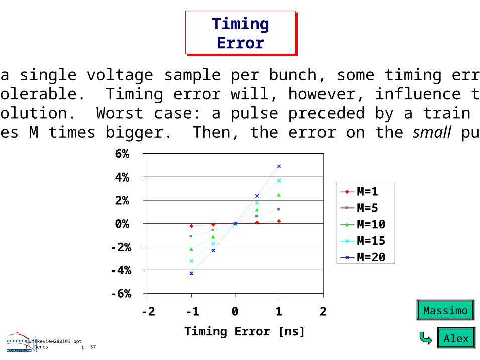
Timing Error
Timing Error
-6%
-4%
-2%
0%
2%
4%
6%
-2 -1 0 1 2
Timing Error [ns]
Amplitude Error [%]
M=1M=5M=10M=15M=20
For a single voltage sample per bunch, some timing erroris tolerable. Timing error will, however, influence the de-convolution. Worst case: a pulse preceded by a train ofpulses M times bigger. Then, the error on the small pulse is
Massimo
Alex

LumiReview280103.pptP. Denes p. 58
Conclusions
Conclusions
Gas detector:• Much work has been done - 2 test beam campaigns(‘00, ‘01)• New mechanical design long-term reliability• Ready for engineering prototype of final design • 2 technologies (gas, CdTe) - both have promising features,
both still need some R&D
• Plan: May ‘03: 25 ns SPS test beam (gas+CdTe)• hadron irradiation of both designs