lumento dx4 - id eide.com.pl/dopobrania/zennio/lumento dx4/manual... · lumento dx4 can regulate...
TRANSCRIPT

Lumento DX4
4-Channel Constant-Voltage PWM Dimmer in DIN Rail Format for DC LED Loads
ZDI-RGBDX4
US
ER
MA
NU
AL
Application programme version: [1.1]
User manual edition: [1.1]_a
www.zennio.com

Lumento DX4
http://www.zennio.com Technical Support: http://support.zennio.com
2
CONTENTS
Contents ........................................................................................................................................ 2
Document Updates ....................................................................................................................... 3
1 Introduction .......................................................................................................................... 4
Lumento DX4 ................................................................................................................. 4 1.1
Installation ..................................................................................................................... 5 1.2
RGB or RGBW Loads ...................................................................................................... 7 1.3
2 Configuration ........................................................................................................................ 8
General .......................................................................................................................... 8 2.1
LED Lighting ................................................................................................................... 9 2.2
2.2.1 Error Identification.............................................................................................. 11
Channels ...................................................................................................................... 15 2.3
2.3.1 Main Configuration ............................................................................................. 15
2.3.2 Switch On/Off ..................................................................................................... 19
2.3.3 Dimming .............................................................................................................. 20
2.3.4 Status Objects ..................................................................................................... 22
2.3.5 Characteristic Curve ............................................................................................ 24
2.3.6 Colour Selection Objects (Only RGB / RGBW channels) ..................................... 27
2.3.7 Custom On/Off .................................................................................................... 29
2.3.8 Auto Off .............................................................................................................. 31
2.3.9 Timers ................................................................................................................. 31
2.3.10 Scenes/Sequences .............................................................................................. 36
2.3.11 Lock ..................................................................................................................... 43
2.3.12 Custom Initialisation ........................................................................................... 44
Inputs ........................................................................................................................... 46 2.4
2.4.1 Binary Inputs ....................................................................................................... 46
2.4.2 Motion Detector ................................................................................................. 46
Master Light Control ................................................................................................... 48 2.5
Manual Control ........................................................................................................... 51 2.6
Annex I. Communication Objects ................................................................................................ 55

Lumento DX4
http://www.zennio.com Technical Support: http://support.zennio.com
3
DOCUMENT UPDATES
Version Changes Page(s)
[1.1]_a
Changes in the application program:
Optimisation of the inputs, master light and motion
detector modules.
Heartbeat functionality added. -
Minor text changes.

Lumento DX4
http://www.zennio.com Technical Support: http://support.zennio.com
4
1 INTRODUCTION
LUMENTO DX4 1.1
Lumento DX4 constitutes the Zennio solution in DIN-rail format for light regulation in
constant-voltage DC LED luminaires. It offers a wide variety of functions:
4 output channels (up to 6000 mA each) parameterisable for different output
configurations, according to the LED module type:
Individual channels: allows an independent control over the different
output channels.
RGBW: allows a joint control over one four-colour LED module. The output
channel will be formed by the colour components (R, G, B and W) of a sole
module, being all of them controlled jointly but with differentiated luminosity
levels.
RGB+W: permits controlling a three-colour LED module, plus an
independent white channel (i.e., an RGB channel plus an individual
channel for the connection of a white LED module).
6 multi-purpose inputs, each of them configurable as:
Binary inputs (i.e., pushbuttons, switches, sensors),
Motion detectors.
Master light control for an easy, out-of-the-box control of a set of luminaires
(or functionally equivalent devices) one of which acts as a general lamp and
the others as secondary lamps.
Manual operation / supervision of the four output channels through the on-
board pushbuttons and LEDs.
Heartbeat or periodical “still-alive” notification.

Lumento DX4
http://www.zennio.com Technical Support: http://support.zennio.com
5
INSTALLATION 1.2
Figure 1. Element diagram
The device connects to the KNX bus via the incorporated terminal (7), which provides
the required power. On the other hand, an additional power supply (12 to 30 VDC) is
required for powering the LEDs. The external power supply is connected to the device
through the corresponding terminal (1). If the external power supply is higher than
expected or the polarity of the connection is wrong, Lumento DX4 will report this
overvoltage and inverse polarity through the Test indicator (8), which will turn blue.
Note: only constant-voltage LED loads can be connected to Lumento DX4.
Once the device is provided with bus power, both the physical address and the
application programme can be downloaded, even if no external power is being
provided. The absence of external power is notified by the Prog./Test LED (8) by
flashing in blue.
The functionality of the main elements of the device is described below:
Prog./Test button: a short press on this button (9) sets the device into the
programming mode, making the associated indicator (8) turns red. If this
button is held while plugging the device into the KNX bus, the device will
enter the safe mode, making the indicator blink in red.
1 External power supply. 2 Colour shift status LED. 3 Colour shift control buttons. 4 Channel control button. 5 Channel status LED. 6 Output channels. 7 KNX connector. 8 Prog./Test LED 9 Prog./Test button. 10 Inputs.
3
10
7
9
2
8
1
5
4
6
6

Lumento DX4
http://www.zennio.com Technical Support: http://support.zennio.com
6
Prog./Test button: a three-second press on this button (9) activates the Test
Mode of the device, which allows verifying the correct connection of the LED
modules.
Once the Test Mode is activate, each of the channels can be switched on
through the corresponding push buttons (4), which will also switch on the
associated indicators (5). A colour scanning can also be performed by
pressing any of the colour shift control buttons (3). The associated LED (2)
will show the current colour.
To leave the Test Mode, just press the Test button again.
Note: while the Test Mode is active, any order received from the KNX bus will
be ignored until the deactivation of the mode.
Inputs (10): ports for the connection of the stripped cables from the external
input elements, such as switches, motion detectors, etc.
To obtain detailed information about the technical features of Lumento DX4 as well as
on security and on the installation process, please refer to the Datasheet, bundled
within the original packaging of the device and also available at the Zennio website,
http://www.zennio.com.

Lumento DX4
http://www.zennio.com Technical Support: http://support.zennio.com
7
RGB OR RGBW LOADS 1.3
Lumento DX4 can regulate the colour and the luminosity level of an RGB or RGBW
diode module.
Although both the colour and the luminosity are controlled by adjusting the level of the
light emitted by the component colours (i.e., a change in the global luminosity is
actually a joint adjustment of the luminosity of the component colours), the luminosity
changes are performed by maintaining the proportion between the components, so
in practice it is not the colour itself, but the light intensity, what is perceived to be
changing.
LED modules are made of different colour components: Red, Green, Blue (RGB) and
White (RGBW). The result of mixing the three first colours in the same proportion is, as
well, the White colour, as shown in Figure 1. Other intermediate colours are obtained
by combining the three main colours (R, G, B) or the four colours (R, G, B, W) in
different proportions. The existence of a specific white component is normally intended
to make these combinations easier and, generally, offers a higher fidelity when the
white colour is shown.
Figure 2. Combination of the Red, Green and Blue colour components
As stated, luminosity (or brightness) refers to the amount of light that the LED strip is
emitting at a given time. The general (or overall) brightness of the set of diodes has
been defined as the brightness of the component that is emitting with the highest
intensity. On the other hand, the regulation of the general brightness is carried out so
the visible colour is perceived as constant, by increasing or decreasing the brightness
of the three colour components together, without losing their proportions.
Note: the colour that is visually perceived (the colour actually obtained) may vary
depending on the LED module and the colour diffuser being used.

Lumento DX4
http://www.zennio.com Technical Support: http://support.zennio.com
8
2 CONFIGURATION
After importing the corresponding database in ETS and adding the device into the
topology of the desired project, the configuration process begins by right-clicking into
the device and selecting Edit parameters.
GENERAL 2.1
The general configuration of Lumento DX4 allows enabling or disabling the following
functionalities:
The binary / analogue Inputs module.
The Master Light Control module.
The Manual Control, which lets operating the output channels through the
on-board pushbuttons for testing or for other purposes.
Heartbeat: periodical “still-alive” notification.
ETS PARAMETERISATION
The tab tree on the left shows the “General” tab in the first place, which contains the
following parameters.
Figure 3. General.
LED Lighting: always enabled; the related parameters are contained in the
“LED Ligthing” tab (see section 2.2).
Inputs: enables or disables the inputs module (see section 2.4).

Lumento DX4
http://www.zennio.com Technical Support: http://support.zennio.com
9
Master Light: enables or disables the master light control (see section 2.5).
Manual Control: enables or disables the manual control (see section 2.6).
Heartbeat (Periodical Alive Notification): this parameter lets the integrator
incorporate a one-bit object to the project (“[Heartbeat] Object to Send ‘1’”)
that will be sent periodically with value “1” to notify that the device is still
working (still alive).
Figure 4. Heartbeat (Periodical Alive Notification).
Note: The first sending after download or bus failure takes place with a delay
of up to 255 seconds, to prevent bus overload. The following sendings match
the period set.
LED LIGHTING 2.2
This block contains all the basic settings common to all the output channels:
The PWM frequency, which defines the regulation speed for the output
voltage (150, 300, 450 or 600 Hz).
Whether the error objects will be required or not. These objects report
anomalous situations affecting the correct behaviour of the device, such as
external power failures, overheating, short-circuits or overloads.
The operation mode of the output channels:
As independent, monochrome channels (up to four).
As a joint RGBW channel.
As a joint RGB channel, plus an independent W channel.

Lumento DX4
http://www.zennio.com Technical Support: http://support.zennio.com
10
ETS PARAMETERISATION
The LED Lighting tab contains the following parameters.
Figure 5. LED Lighting.
PWM Frequency: “150”, “300”, “450”, or “600” (by default) Hz.
Error Objects: enables or disables the error notification objects (see section
2.2.1).
Outputs Configuration: sets the control type for the outputs: “Individual
Channels” (by default), “RGBW” and “RGB+W”. In case of opting for the first
option, it will be possible to selectively enable or disable each of the individual
channels through the specific checkboxes
Note: hereafter, the prefix “[Ch]” will be added to certain object names to refer to an
output channel, although depending on the above parameter the actual name may
begin with “[1]”, “[2]”, “[3]”, “[4])”, “[RGBW]”,”[RGB]”, “[W]”, “[R]”, “[G]”, or “[B]”.
With independence of the channel type, three control objects per channel will be
included in the project topology after the channel activation:
“[Ch] Switch On/Off”: one-bit object destined to perform a general switch-on
(“1”) or switch-off (“0”) of the LED strip.
“[Ch] Relative Dimming”: four-bit object destined to step-dimming the
brightness (luminosity) level. Steps (upwards or downwards) of 1%, 3%, 6%,
12%, 25%, 50% and 100% are possible.

Lumento DX4
http://www.zennio.com Technical Support: http://support.zennio.com
11
“[Ch] Absolute Dimming”: one-byte object to specify a particular light level
(by setting the target percentage value) over the general brightness level.
In the case of an RGB or RGB+W control, an additional parameter (Independent
Control Objects) will be provided to allow enabling specific control objects per colour
component in addition to the analogous, joint control objects.
Example
Assume that the outputs configuration is RGBW and the LED module shows the colour
[25%, 50%, 0%, 3%] at a given time.
A regulation order of ‘70%’ through “[RGBW] Absolute Dimming” will set the
component with the highest illumination level to 70%, while the others will vary
proportionally (70 / 50 = 1.4). The output will become [35%, 70%, 0%, 4.2%].
A regulation order through “[RGBW] Relative Dimming” to decrement the new
light level by 25% will make the component with the highest level (G) decrease its
value by 25% (becoming 45%), while the others will vary proportionally (45 / 70 =
0.64). Therefore, the output colour will become [22.5%, 45%, 0%, 2.7%].
2.2.1 ERROR IDENTIFICATION
The error objects send automatic notifications to the KNX bus whenever the device
detects abnormal situations, such as external power failures, overheating, short-circuits
or overloads. When any of these is detected, the corresponding object will be sent with
a value of “1” every thirty seconds. Once the error is over, it will be sent once with a
value of “0”.
2.2.1.1 OVERHEATING
This situation takes place when the system temperature becomes higher than 75ºC. In
such case, the light level of the output channels will be decreased to 30% and the Test
indicator will start blinking in blue colour.
If the system reaches 80ºC, the outputs will be turned off.

Lumento DX4
http://www.zennio.com Technical Support: http://support.zennio.com
12
Once the temperature drops below 70ºC, the value "0" will be sent through the error
object, although for safety reasons the outputs will remain at their current level, until a
new dimming order is received.
Note: even if the error notification objects have not been enabled in parameters, the
overheating protection remains always enabled.
2.2.1.2 EXTERNAL VOLTAGE ERROR
This situation takes place when an unexpected power supply is detected, i.e., due to
any of these events:
Absence of power (disconnected source).
Polarity inversion in the power supply.
External voltage higher than allowed (30V).
Once the situation is over, the outputs will recover their previous state.
2.2.1.3 SHORT-CIRCUIT OR OVERLOAD
Once the system detects an overload situation, all the outputs will be automatically
switched off. Next, the device will perform a per-output scan to determine whether the
overload is due to a short circuit on any of them. In such case, the overload error will
end and the short circuit error will be activated while only the output under such
situation is left switched off.
Notes:
The detection of these errors is only possible in the course of a regulation.
Moreover, they may not be detectable if the level of regulation is too low.
When an overload error is received, a short circuit may also be occurring.
2.2.1.4 ERROR NOTIFICATION
Under any of the above errors, even if the error notification remains disabled, a visual
notification will notify it through the on-board LEDs (see section 1.2).

Lumento DX4
http://www.zennio.com Technical Support: http://support.zennio.com
13
In case of error concurrence, only the one with the highest priority will be indicated.
Table 1 shows these errors, ordered by priority.
ERROR NOTIFICATION
External Voltage Error
Prog./Test LED starts blinking in blue colour with a duration of 1s every 2s.
+ Prio
rity –
Short-circuit or Overload
Channel status LED and Prog./Test LED flash in green and blue with a
duration of 100ms every second.
Overheating Prog./Test LED flashes in
blue colour with a duration of 100ms every 2s.
Table 1. Visual Error Notification
ETS PARAMETERISATION
The error notification objects entail no particular parameterisation, other than enabling
them in the general parameters of the “LED Ligthing” tab (see section 2.2). This
incorporates the following objects to the project topology:
“Error: Overheating”,
“Error: Overload”,
“Error: External Voltage”,
“[Ch] Error: ShortCircuit”.

Lumento DX4
http://www.zennio.com Technical Support: http://support.zennio.com
14
As already stated, in case any of detecting any of the above errors, the corresponding
object will be sent periodically with a value of “1”. Once the abnormal situation is over,
it will be sent (once) with a value of “0”.

Lumento DX4
http://www.zennio.com Technical Support: http://support.zennio.com
15
CHANNELS 2.3
Although it is possible to perform a per-component, or an RGBW, or an RGB+W
control of the outputs, the functionality is analogous in all cases. The following sections
describe this functionality, highlighting the details that differ from one case to another.
2.3.1 MAIN CONFIGURATION
The main configuration of the output channel entails the following options:
Economical Mode: defines the maximum dimming value (in percentage from
50% to 100%) that can be applied to the channels through a dimming order. If
this parameter is set to a value other than 100%, a proportional reduction of
the luminosity will be applied. However, Lumento DX4 will always send
luminosity values between 0% and 100% to the KNX bus.
Example:
A value of 80% is assigned to this parameter. In such case, dimming orders
for a luminosity of 100% will actually set a luminosity of 80%, although the
status object will show a value of 100%. Analogously, orders for a luminosity
of 50% will actually set it at 40%, although the status object will show 50%.
Dimming times: the dimming time is the length of the transition between off
(0%) and the maximum luminosity level (100%), and therefore determines the
speed of the regulation. Up to three different dimming times can be
defined and afterwards assigned to different functions and actions. Their
values may also be changed through three communication objects (one per
each dimming time).
Note: since the dimming time refers to the transition from the minimum
luminosity level (off) to the maximum luminosity level, enabling the
economical mode will increase the dimming speed, as the maximum
luminosity level becomes lower but must be reached in the same
(parameterised) time.

Lumento DX4
http://www.zennio.com Technical Support: http://support.zennio.com
16
Independent Control Objects (RGBW / RGB+W only): brings the option to
control each of the colour components individually (in addition to the joint
control) analogously as in the individual channel output configuration.
White Colour Only On W Channel (RGBW only): sets whether the white
colour should be obtained only by using the W channel (remaining the other
channels off) or also by combining the R, G and B channels.
On the other hand, it is possible to configure a set of custom functions per channel:
The status objects associated to the channel (On/Off status and dimming
status). See section 2.3.4.
A characteristic curve for the luminosity regulation. See section 2.3.5.
Colour selection objects (RGBW / RGB+W only) for the selection and
control of the resulting colour, either through a direct selection, or by
assigning values to the colour components, or through a colour scan
sequence. See section 2.3.6.
Up to four custom on/off switches, with different dimming values and times.
See section 2.3.7.
Automatic switch-off. See section 2.3.8.
Timed or delayed on/off switches. See section 2.3.9.
Scenes and sequences. See section 2.3.10.
A channel lock control, to disable it when required. See section 2.3.11.
A custom channel initialisation. See section 2.3.12.
ETS PARAMETERISATION
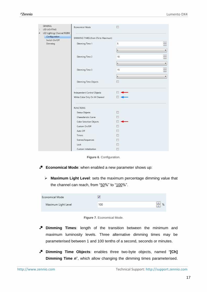
The Configuration tab of a specific channel contains the parameters shown in Figure 6.
Note that the parameters highlighted in red are only available under an RGB+W or
RGBW control, while the parameter highlighted in blue is only available under an
RGBW control.
Lumento DX4
http://www.zennio.com Technical Support: http://support.zennio.com
17
Figure 6. Configuration.
Economical Mode: when enabled a new parameter shows up:
Maximum Light Level: sets the maximum percentage dimming value that
the channel can reach, from “50%” to “100%”.
Figure 7. Economical Mode.
Dimming Times: length of the transition between the minimum and
maximum luminosity levels. Three alternative dimming times may be
parameterised between 1 and 100 tenths of a second, seconds or minutes.
Dimming Time Objects: enables three two-byte objects, named “[Ch]
Dimming Time n”, which allow changing the dimming times parameterised.

Lumento DX4
http://www.zennio.com Technical Support: http://support.zennio.com
18
These objects accept values in the range 1 to 6000 (seconds).
Independent Control Objects (RGBW / RGB+W only): enables additional
communication objects per colour components, analogous to those in an
individual channel control. These objects are:
“[X] Switch On/Off”: one-bit object for a switch-on (“1”) or a switch-off (“0”)
of component X.
“[X] Relative dimming”: four-bit object destined to step-dimming the
luminosity level of component X. Steps upwards or downwards (of 1%,
3%, 6%, 12%, 25%, 50% or 100%) are possible.
“[X] Absolute dimming”: one-byte object destined to specify a particular
light level (by setting the target percentage value) over the brightness level
of component X.
Note: [X] refers to [R], [G], [B] or [W].
White Colour Only On W Channel (RGBW only).
Functions::
Status Objects: see section 2.3.4.
Characteristic Curve: see section 2.3.5.
Colour Selection Objects: see section 2.3.6.
Custom On/Off: see section 2.3.7.
Auto Off: see section 2.3.8.
Timers: see section 2.3.9.
Scenes / Sequences: see section 2.3.10.
Lock: see section 2.3.11.
Custom initialization: see section 2.3.12.

Lumento DX4
http://www.zennio.com Technical Support: http://support.zennio.com
19
2.3.2 SWITCH ON/OFF
Lumento DX4 lets configuring the general On/Off switch control, so that these actions
are performed immediately or through a smooth regulation (according to one of the
three configurable dimming times; see section 2.3.1).
Furthermore, it is possible to specify the illumination level that the channel will adopt
when a general switch-on order is executed: either a value defined in parameters or the
value that was active prior to the switch off (i.e., a memory switch-on).
Note that, in RGB / RGBW channels, the colour will always be preserved when the
channel is switched off and afterwards on. Configuring a specific illumination level only
affects to the light intensity, not to the ratio of the different colour components.
ETS PARAMETERISATION
The Switch On/Off window contains the following parameters.
Figure 8. Switch On/Off
On/Off Dimming Time: “At Once” (default option), “Dimming Time 1”,
“Dimming Time 2”, “Dimming Time 3”. See section 2.3.1.
Switch On Value: allows selecting the general illumination level that will be
adopted by the channel when the value “1” is received through “[Ch] Switch
On/Off”:
“Last On Value” (default option).
Additionally, Overwrite Last On Value determines whether a second
switch-on order should set the maximum illumination level and therefore
overwrite the last memorised value.
“Defined Value”: 0% to 100%.

Lumento DX4
http://www.zennio.com Technical Support: http://support.zennio.com
20
Example:
“Last On Value” is selected with an RGB channel configuration.
The LED module is on, and in orange colour (100%, 20%, 0%). If '1' is received
through “[RGB] Switch On/Off”, it will remain in the same state.
The channel is switched off by sending one ‘0’ through “[RGB] Switch On/Off”. If
afterwards the value ‘1’ is received through the same object, the channel will show
orange colour again.
A ‘Decrement by 50%’ relative dimming order is sent through “[RGB] Relative
Dimming”, so the channel switches to (50%, 10%, 0%). Afterwards, an identical
order is sent again, causing the switch-off of the channel. If it is eventually
switched on through “[RGB] Switch On/Off”, the orange colour will be restored at
level (50%, 10%, 0%).
On the contrary, under a “Defined Value” configuration (with value 80%):
The channel module is on, and in orange colour (100%, 20%, 0%).
A “Decrement by 50%” relative regulation order is sent through “[RGB] Relative
Dimming”. The colour ratio is preserved, reducing the illumination level to (50%,
10%, 0%). Afterwards, the channel is switched off.
When a ‘1’ is received through “[RGB] Switch On/Off”, the illumination level is set
to 80% but preserving the colour ratio, which results in (80%, 16%, 0%).
2.3.3 DIMMING
Lumento DX4 provides two general dimming modes besides the general On/Off
Switch:
Relative Dimming: modifies the luminosity level through orders to increment
or decrement it by fixed percentages (“1.6%”, “3.1%”, “6.3%”, “12.5%”, “25%”,
“50%” or “100%”), which will be added to or subtracted from the current
luminosity level of the channel. A four-bit object is provided for the reception
of the relative dimming orders.
Absolute dimming: modifies the luminosity level through orders that specify

Lumento DX4
http://www.zennio.com Technical Support: http://support.zennio.com
21
the desired target value, regardless of the current value of the channel. A
one-byte object is provided for the reception of the absolute dimming orders.
Both regulation modes will be subject to the maximum and minimum illumination
levels specified in parameters (which may be helpful depending on the response of
the LED loads). It is also possible to configure which of the three already-defined
dimming times should apply to perform the entire transition between 0% and
100% (i.e., the dimming speed), unless an immediate transition is preferred.
ETS PARAMETERISATION
The “Dimming” window, available from the start, contains the following parameters:
Figure 9. Dimming
RELATIVE DIMMING (4 bits): this section allows setting up the configuration
of the relative dimming function and the “[Ch] Relative Dimming” four-bit
object.
Relative Dimming Time: “At Once”, “Dimming Time 1”, “Dimming Time 2”,
“Dimming Time 3”. See section 2.3.1.
Maximum Dimming Value: sets the maximum illumination percentage
(between “51%” and “100%”) that will be allowed in the channel. If an order
implying an illumination level beyond this limit is received, the channel will
adopt this maximum level, as the status object will reflect.

Lumento DX4
http://www.zennio.com Technical Support: http://support.zennio.com
22
Minimum Dimming Value: sets the minimum illumination percentage
(between “0%” and “50%”) that will be allowed in the channel. If an order
implying an illumination level below this limit is received, the channel will
adopt this minimum level (unless “Allow Switching Off via Relative
Dimming” is active; see below), as the status object will reflect.
Allow Switching On via Relative Dimming: sets whether a channel that
is found to be off should be switched on in case a relative increase order is
received, or whether the order should be ignored.
Allow Switching Off via Relative Dimming: sets whether the device
should switch off the channel in case the channel is found to be on and a
light decrease order is received implying a luminosity value of 0% (or of
any value under the minimum dimming value parameterised), or simply
ignore the order.
ABSOLUTE DIMMING (1 byte): this section allows setting up the configuration
of the absolute dimming function and the one-byte object “[Ch] Absolute
Dimming”. All parameters are analogous to those for the relative dimming.
2.3.4 STATUS OBJECTS
Lumento DX4 provides different objects that report the current illumination state of the
output channel:
A one-bit On/Off object,
A one-byte object, which indicates the illumination level (in percentage),
A three-byte object (in the case of an RGBW or RGB+W configuration),
which indicates the illumination level (in percentage) of the three main colour
components.
Independent status objects (in the case of an RGBW or RGB+W
configuration), i.e.:
A one-bit object (On/Off) per colour component.
A percentage one-byte object per colour component.

Lumento DX4
http://www.zennio.com Technical Support: http://support.zennio.com
23
ETS PARAMETERISATION
Figure 10. Status Objects
The activation of this function brings in a new tab to the channel configuration within
the side menu, as well as the following communication objects:
“[Ch] On/Off (Status)”: one-bit object that indicates if the channel is switched
off (“0”) or on (“1”).
“[Ch] Dimming Value (Status)”: one-byte object that represents the
illumination percentage of the channel (0% to 100%).
Note: under RGBW and RGB+W output configurations, this general
illumination level will always refer to that of the colour component (R, G, B or
W) with the maximum illumination level at the moment.
“[Ch] RGB Dimming Values (Status)” (RGBW / RGB+W only): three-byte
object which indicates the illumination levels of the three main colour
components. Each byte represents, respectively, the R, G and B
components.
Regarding the parameters contained in the Status Objects tab:
Independent Status Objects (RGBW / RGB+W only): “Disabled” by default.
Its activation will enable two additional status objects for each single channel
(R, G, B, W):
“[X] On/Off (Status)”: one-bit object that indicates if the component is
switched off (“0”) or on (“1”).
“[X] Dimming Value (Status)”: 1-byte: one-byte object that represents the
illumination percentage of the component (0% to 100%).

Lumento DX4
http://www.zennio.com Technical Support: http://support.zennio.com
24
Send Luminosity While Dimming: makes the “[Ch] Dimming Value
(Status)” object be sent periodically to the bus throughout the dimming
process. If enabled, also the following parameter will appear:
Sending Period (with Value Change): defines the sending cycle time (1
to 100 seconds) of the status object.
Notes:
The status object is sent unless its value has not changed since the
previous sending.
Under an RGBW / RGB+W configuration, “[Ch] RGB Dimming Values
(Status)” will be sent as well together with the “[X] Dimming Value
(Status)” individual status objects, if enabled.
As soon as the channel illumination level is greater than 0%, the “[Ch]
On/Off (Status)” object will be sent with the value “1”, while the value “0”
will be sent as soon as it becomes 0% again. The per-component “[X]
On/Off (Status)” objects, if enabled, will behave analogously.
2.3.5 CHARACTERISTIC CURVE
By default, all control values received are directly applied to the loads (through a PWM
signal) as shown in Figure 11.
Figure 11. Default Control Curve.
25%
25%
100%
100%
Control Value
Actual Regulation

Lumento DX4
http://www.zennio.com Technical Support: http://support.zennio.com
25
For a more complex control, the device can implement a characteristic curve, defined
through four custom control points, i.e., four pairs of values of the form (x, y). This
lets the definition of custom curves, such as:
Figure 12. Custom Control Curves.
In case the first and last points do not correspond (respectively) to values 0% and
100%, the characteristic curve will be defined as follows (see Figure 12 and Figure 13):
For control values lower than that of the first point, the actual regulation
value will be 0%. For example, in Figure 13 all control values under 20% imply
a regulation value of 0%.
For control values greater than that of the last point, the actual regulation
value will be 100%. For example, in Figure 13 all control values over 80% imply
a regulation value of 100%.
Notes:
Please ensure that different control values are assigned different
regulation values. Otherwise, the regulation may present issues.
Intermediate values between the user-defined points are calculated by linear
interpolation.
The status objects will always refer to the control values, between 0% and
100%, with independence of the curve being implemented, which is typically
irrelevant for the final user.
40%
25%
80%
90%
Control
Value
Actual Regulation
0% 31%
25%
80%
100%
Control
Value
Actual Regulation
0%0%
19%30%

Lumento DX4
http://www.zennio.com Technical Support: http://support.zennio.com
26
Figure 13. Values Out of Range
ETS PARAMETERISATION
After enabling “Characteristic Curve” in the Configuration screen (see section 2.3.1),
a new tab will be incorporated into the tab tree on the left.
Figure 14. Characteristic Curve.
Contains the parameters required to define up to four points of the characteristic curve:
Control Value (%): input value received through the one-byte control object
(value in the “x” axis).
PWM Value (%): real value applied to the output to control the load when the
above control value is received (value in the “y” axis).
Note: please ensure that points 1 through 4 have different control values (i.e., each
control value must correspond to only one regulation value), and that these values are
20%
30%
80%
100%
Control Value
Actual Regulation
0% 19% 81%
70%
1
2

Lumento DX4
http://www.zennio.com Technical Support: http://support.zennio.com
27
sorted in ascending order (control value 1 < control value 2 < control value 3 < control
value 4). Otherwise, the output regulation function may behave abnormally.
2.3.6 COLOUR SELECTION OBJECTS (ONLY RGB / RGBW CHANNELS)
For RGB, RGBW and RGB+W configurations, Lumento DX4 provides different
procedures for selecting the desired joint colour:
Through a three-byte object that sets the illumination level (in percentage)
of the main colour components (R, G and B).
Though a one-byte direct colour object, which permits selecting (by
sending an integer value between 0 and 21) any of the following twenty-two
pre-set colours:
Scene (Value) Colour R G B W
1 (0) Off 0 0 0 0
2 (1) White 0 0 0 255
3 (2) White – Light 128 128 128 128
4 (3) Blue 0 0 255 0
5 (4) Blue – Light 102 204 255 51
6 (5) Blue – Navy 0 0 102 0
7 (6) Blue – Cyan 0 255 255 0
8 (7) Blue – Turquoise 0 255 77 51
9 (8) Blue – Lavender 128 128 255 51
10 (9) Green 0 255 0 0
11 (10) Green – Light 128 255 51 51
12 (11) Green – Dark 0 102 0 0
13 (12) Green – Lime 128 255 0 13
14 (13) Red 255 0 0 0
15 (14) Red – Pink 255 0 77 0
16 (15) Red – Dark 102 0 0 0
17 (16) Red – Magenta 255 0 255 0
18 (17) Red – Fuchsia 255 26 51 0
19 (18) Yellow 255 255 0 0
20 (19) Orange 255 51 0 0
21 (20) Lilac 255 128 128 0
22 (21) Purple 170 0 255 0
Table 2. Direct Color
By triggering a colour scan, which will start from the nearest stage among
those shown in the figure below, and may be interrupted once the desired
colour is reached.

Lumento DX4
http://www.zennio.com Technical Support: http://support.zennio.com
28
Figure 15. Colour Scan
ETS PARAMETERISATION
Enabling the Colour Selection Objects parameter (disabled by default) will enable as
well the following communication objects:
“[Ch] RGB Colour”: three-byte object which allows setting the luminosity of
each component (between 0 and 255). Thus, the first byte represents the red
channel (R) illumination, while the second byte represents that of the green
channel (G) and the third one refers to the blue channel (B).
“[Ch] Direct Colour”: one-byte object for choosing one of the 22 pre-set
colours (Table 2).
“[Ch] Colour Shift”: two homologous objects of one-bit and four-bit size,
respectively, to start or stop the colour scan function (Figure 15).
The one-bit object is destined to combine this functionality with a simple,
binary control.
The four-bit object allows integrating this functionality into light-dimming
one-button controls: orders to increase the light level will trigger a forward
colour scan, while orders to decrease the light level will trigger a backward
colour scan. Table 3 shows the length of the scan depending on the step
order received (note that the entire scan takes place in any of the cases).
Increase/Decrease Period (s) 100% 30 50% 25 25% 20
12.5% 15 6.25% 12 3.12% 7 1.5% 4 Stop Interrupt scan
Table 3. Scan length depending on the step order received

Lumento DX4
http://www.zennio.com Technical Support: http://support.zennio.com
29
Example:
Suppose a one-button (toggle) dimming control on the TMD Plus from Zennio. If it has
been assigned a dimming step of 25% and the communication objects (including the
status objects) have been properly linked to those in Lumento C:
Being the LED module off, when the user performs a long press on the button,
TMD Plus sends an order to increase by 25%. The LED module switches on and
the colour scan begins, with a 20 second period.
When the user releases the button TMD Plus sends an order stop, so the colour
shift is interrupted. From that moment on, the user may perform further long
presses to start over the colour scan, or a short press to switch off the module.
2.3.7 CUSTOM ON/OFF
This function offers up to four additional On/Off controls for the output channel, and
therefore up to four new communication objects to switch the load on and off.
These additional controls may be customised with specific illumination levels for the
“on” and “off” states, and may also be configured to perform an immediate or soft
dimming.
ETS PARAMETERISATION
Once enabled, the following parameters will show in ETS:
Figure 16. Custom On/Off
On/Off ‘n’: “Disabled” by default. Once enabled, the “[Ch] Custom On/Off
‘n’” one-bit object and a specific parameter tab will show in ETS:

Lumento DX4
http://www.zennio.com Technical Support: http://support.zennio.com
30
Figure 17. Custom On/Off (detail)
This screen allows setting up the specific behaviour when a “1” or a “0” are received
through object “[Ch] Custom On/Off ‘n’”:
Action for Bit Value ‘1’: (only RGB / RGBW channels): sets the action to
perform when a “1” is received through “[C] Custom On/Off ‘n’”. One of the
following actions may be chosen:
“Luminosity” (default): sets a specific illumination percentage (0% to 100%)
to be applied to the channel when a “1” is received.
“Predefined Colour”: permits selecting one of the pre-set colours (see
Table 2).
“RGB/RGBW Colour”: sets a specific luminosity value (0 to 255) for each
of the colour components.
Dimming Value for Bit Value ‘1’ (only individual channels and white
channel): equivalent to the above “Luminosity” option, although it only applies
to a specific individual channel.
Dimming Time for Bit Value ‘1’: “At Once”, “Dimming Time 1”, “Dimming
Time 2”, “Dimming Time 3”. Allows selecting the dimming type (in terms of
speed) which will be applied to the transition from current level to that set in
the previous parameter. See section 2.3.1.
Action for Bit Value ‘0’: analogous to the above Action for Bit Value ‘1’,
but referred to the arrival of the value “0” from the bus.

Lumento DX4
http://www.zennio.com Technical Support: http://support.zennio.com
31
Dimming Value for Bit Value ‘0’: analogous to the above Dimming Value
for Bit Value ‘1’, but referred to the arrival of the value “0” from the bus.
Dimming Time for Bit Value ‘0’: analogous to the above Dimming Time for
Bit Value ‘0’, but referred to the arrival of the value “0” from the bus.
2.3.8 AUTO OFF
If the Auto Off function is enabled, the load controlled by the channel will automatically
turn off after a certain time with a light level lower than a parameterisable limit.
The Auto Off function counts the time elapsed after the output falls below a certain
threshold light level. If this count exceeds the parameterised timeout, Lumento DX4 will
turn the load off. The count will stop if an order to increase back the light level over that
limit is received.
ETS PARAMETERISATION
Figure 18. Auto Off
The only parameters contained by the Auto Off specific screen are:
Luminosity (Threshold): sets the desired light level (5% to 70%) that will
trigger the time count.
Time: sets the time that should elapse before turning the channel off. The
available values are 10 to 255 seconds and 1 to 100 minutes.
2.3.9 TIMERS
This function allows configuring a simple timing and a flashing sequence in the
output channel, being it possible to enable or disable both functions independently.

Lumento DX4
http://www.zennio.com Technical Support: http://support.zennio.com
32
The simple timing function consists in a switch-on of the channel (with an optional
delay) on the reception of the corresponding trigger object, and a later switch-off, either
automatic (after a certain period) or triggered through the corresponding bus object,
also with an optional delay in this case.
On the other hand, the flashing function consists in switching the channel on and off a
certain number of times or indefinitely, according to the parameters, once the
corresponding object is received.
ETS PARAMETERISATION
Once enabled, the following parameters will show in ETS:
Figure 19. Simple Timer
SIMPLE TIMER: checkbox to enable or disable the simple timer function, as
well as its specific parameters and the “[Ch] Simple Timer” one-bit object,
which will trigger a delayed switch-on when the value “1” is received, and a
delayed switch-off when the received value is “0”.
On Delay: sets a delay between the reception of the simple timer trigger
order (value “1” through object “[Ch] Simple Timer”) and the actual

Lumento DX4
http://www.zennio.com Technical Support: http://support.zennio.com
33
switch-on of the channel, in the range 0 to 100 tenths of a second,
seconds or minutes.
Off Delay: sets a delay between the reception of the simple timer stop
order (value “0” through object “[Ch] Simple Timer”) and the actual
switch-off of the channel, in the range 0 to 100 tenths of a second,
seconds or minutes.
On Duration: sets the time the output channel must remain on before
being automatically switched off (unless a simple timer stop order is
received), in the range 0 to 100 tenths of a second, seconds or minutes.
The value “0” (default option) will disable the automatic switch-off, thus
making the simple timer switch-on state endless.
Warning Time: sets an anticipation time (0 to 100 tenths of a second,
seconds or minutes) prior to the switch-off action so that the channel
reduces to 50% the current luminosity to notify that the timer action is
about to end. Moreover, the “[Ch] Warning Time (Status)” object will
acquire a value of “1” while this luminosity reduction is running. If set to
zero, no warning will take place. Note that this time needs to be lower than
the ON Duration time.
Action in Case of Retriggering: sets the action to be performed in case
the value “1” is received several times:
Nothing: the current time count will not be restarted.
Restart: the time count of the On Duration will be restarted from zero.
Multiply: the On Duration will become ‘n’ times the configured time,
being ‘n’ the number of times the value “1” is received.

Lumento DX4
http://www.zennio.com Technical Support: http://support.zennio.com
34
Example:
On Delay: 2 s
Off Delay: 4 s
On Duration: 6 s
On Value: 100%
On/Off Dimming Time: At Once.
Restart
Multiply
On Action (only RGB / RGBW channels): sets the action to be performed
when the value “1” is received through “[Ch] Simple Timer”: “Luminosity”,
“Predefined Colour” and “RGB/RGBW Colour” (analogously as in section
2.3.7).

Lumento DX4
http://www.zennio.com Technical Support: http://support.zennio.com
35
On Value (only individual or W channels): analogous to choosing
“Luminosity” in the previous parameter (On Action).
On/Off Dimming Time: “At Once”, “Dimming Time 1”, “Dimming Time 2”,
“Dimming Time 3” (see “Dimming times” in section 2.3.1).
Note: the simple timer function will be interrupted whenever any other
dimming action is commanded, no matter if it falls within the On Duration or
during the on / off delays.
FLASHING: checkbox to enable or disable the flashing function, as well as its
specific parameters and the “[Ch] Flashing” one-bit object, which will trigger
an On-Off-On… sequence when the value “1” is received, and will interrupt it
by sending the value “0”.
Figure 20. Flashing
On Duration: sets the length of each “On” stage during the sequence, in
the range 1 to 100 tenths of a second, seconds or minutes.
Of Duration: sets the length of each “Off” stage during the sequence, in
the range 1 to 100 tenths of a second, seconds or minutes

Lumento DX4
http://www.zennio.com Technical Support: http://support.zennio.com
36
Repetitions: sets the number of iterations of the sequence, between 0 and
255. The value “0” (default option) causes an endless repetition, until an
order to interrupt the sequence is received.
On Action (only RGB / RGBW channels): sets the action to be performed
during the “On” stages of the sequence: “Luminosity”, “Predefined Colour”
and “RGB/RGBW Colour” (analogously as in section 2.3.7).
On Value (only individual or W channels): analogous to choosing
“Luminosity” in the previous parameter (On Action).
Final Action (only RGB / RGBW channels): sets the action to be
performed after the last iteration of the sequence, as well as when the
value “0” is received through “[Ch] Flashing”: “Luminosity”, “Predefined
Colour” and “RGB/RGBW Colour” (analogously as in section 2.3.7).
Final Value (only individual or W channels): analogous to choosing
“Luminosity” in the previous parameter (Final Action)
2.3.10 SCENES/SEQUENCES
This feature allows defining different scenes, i.e., specific ambiences or dimming
sequences, which may be activated by sending the corresponding trigger value to the
on-byte scenes / sequences objects.
Lumento DX4 offers up to five scenes / sequences per each individual or white
channel and up to ten scenes / sequences per RGB or RGBW channel.
ETS PARAMETERISATION
Once this function has been enabled, the following objects will show in ETS:
“[Cx] Scenes/Sequences”: triggers the scene or sequence whose number
corresponds to the value received through the object (see below).
“[Cx] Start/Stop Sequence” (one bit): allows to start the last sequence
performed, or re-start the one currently in execution (sending the value “1”),
as well as interrupting the current sequence (value “0”).

Lumento DX4
http://www.zennio.com Technical Support: http://support.zennio.com
37
Note: the “[Cx] Start/Stop Sequence” object only applies to sequences, and
has no effect over static scenes. Moreover, after a download from ETS
(partial or complete), if the value “1” is sent through this object, Lumento DX4
will trigger the first, non-static sequence parameterised.
The “Scenes/Sequences” tab in ETS contains the following parameters:
Figure 21. Scenes/Sequences
Each scene / sequence activated from this screen will have a specific tab associated,
labelled as “Scene/Sequence ‘n’” and containing the following parameters:
Figure 22. Scene configuration
The following parameters are available:
Scene/Sequence Number: sets the scene/sequence identifying number
(from 1 to 64) whose reception (decreased by 1, according to the KNX
standard) through the “[Ch] Scenes/Sequences” object will make the device
trigger the scene/sequence.
Scene/Sequence Type: selects the desired action on the activation of the
scene/sequence:

Lumento DX4
http://www.zennio.com Technical Support: http://support.zennio.com
38
“Luminosity” (only RGB / RGBW channels): the scene activation will
consist in setting a fixed illumination value (0% to 100%) in the channel.
The following parameters will show up:
Luminosity: sets the desired illumination level percentage.
Dimming Type: “At Once”, “Dimming Time 1”, “Dimming Time 2”,
“Dimming Time 3”. See section 2.3.1.
In this case it will be also possible to save scenes. If a scene saving order
(values 128 to 191) is received, the current luminosity level of the channel
will be taken into account for later triggers of the corresponding scene.
“Predefined Colour” (only RGB / RGBW channels): the execution of the
scene will consist in setting a specific pre-set colour. See Table 2.
This option also entails the following parameters:
Predefined Colour: sets the desired colour.
Dimming Type: “At Once”, “Dimming Time 1”, “Dimming Time 2”,
“Dimming Time 3”. See section 2.3.1.
“RGB Colour/ RGBW Colour” (only RGB / RGBW channels): the execution
of the scene will consist in setting fixed values to the R, G, B and W (if
existing) colour components. The following parameter will also be
available:
Dimming Type: “At Once”, “Dimming Time 1”, “Dimming Time 2”,
“Dimming Time 3”. See section 2.3.1.
“Fixed Value” (only individual or W channels): the scene activation will
consist in setting a fixed illumination value (0% to 100%) in the channel.
“Predefined Sequence” (only RGB / RGBW channels): the execution of the
scene will consist in a predefined colour sequence, configurable through
the following parameters::

Lumento DX4
http://www.zennio.com Technical Support: http://support.zennio.com
39
Predefined Sequence: “Colourful” (default), “Cool Colours”, “Warm
Colours”, “Sunrise”, “Sunset” or “TV/Presence Simulation”. The specific
colour transition of each sequence is listed below.
“Colourful” (cyclic sequence).
Step# Colour RGBW Period
1 Red 255/0/0/0 t/5
2 Green 0/255/0/0 t/5
3 Blue 0/0/255/0 t/5
4 Magenta 255/0/255/0 t/5
5 Yellow 255/255/0/0 t/5
“Cool colours” (cyclic sequence).
Step# Colour RGBW Period
1 Blue 1 100/128/255/0 t/5
2 Green 1 20/255/100/0 t/5
3 Green 0/255/0/0 t/5
4 Green 2 0/255/77/0 t/5
5 Blue 0/0/255/0 t/5
“Warm colours” (cyclic sequence).
Step# Colour RGBW Period
1 Red 255/0/0/0 t/5
2 Magenta 255/0/255/0 t/5
3 Pink 255/0/77/0 t/5
4 Orange 255/51/0/0 t/5
5 Yellow 255/255/0/0 t/5
“Sunrise” (non-cyclical sequence; executed only once, performs a
colour transition from darker to brighter colours, which will depend on
the Final Luminosity parameterised)
Step# Colour RGBW Luminosity Period
1 Switched Off 0/0/0/0 0% 0
2 Red 63/0/0/0 25% t/4
3 Orange 128/25/0/0 50% t/4
4 Yellow 191/191/0/0 75% t/4
5 White 255/255/255/0 100% t/4

Lumento DX4
http://www.zennio.com Technical Support: http://support.zennio.com
40
“Sunset” (non-cyclical sequence; executed only once, performs a
colour transition from brighter to darker colours, which will depend on
the Final Luminosity parameterised).
Step# Colour RGB/RGBW Luminosity Period
1 White 255/255/255/0 100% 0
2 Yellow 191/191/0/0 75% t/4
3 Orange 128/25/0/0 50% t/4
4 Red 63/0/0/0 25% t/4
5 Switched Off 0/0/0/0 0% t/4
“TV/Presence Simulation” (sequence showing random colours and
times; the colour transitions are immediate).
Time (not available for “TV/Presence Simulation”): sets the length of a
full cycle of the sequence, between 1 and 100 minutes.
Luminosity (not available for “Sunset” or “Sunrise”): sets the luminosity
that will be applied along the sequence execution, between “0%” and
“100%”.
Final Luminosity (“Sunrise” only): sets the luminosity to be applied at
the end of the sequence, between 0% and 100%.
Initial Luminosity. (“Sunset” only): sets the luminosity to be applied at
the beginning of the sequence, between 0% and 100%.
Send Luminosity During the Sequence: enables or disables a
periodic sending of the status object while the sequence is running.
Note: this option will not be available unless parameter Send
Luminosity While Dimming has been activated (see section 2.3.2).
The sending period will be in accordance to the one configured there.

Lumento DX4
http://www.zennio.com Technical Support: http://support.zennio.com
41
Figure 23. Pre-defined sequence
“Custom Sequence”: brings the option to define sequences up to five
steps, and to configure the following parameters:
Cyclic: “Enabled” (after the last step, the sequence will start over) or
“Disabled” (default option; in such case, after the last step, it will be
possible to automatically trigger any other sequence parameterised).
Next Sequence: only available if Cyclic has been disabled; allows the
execution of another sequence after the last step of the current
sequence. The options are “No Sequence” and “Sequence ‘n’” (being ‘n’
a value between 1 and 5 for individual / white channels, or between 1
and 10 for RGB / RGBW channels).
Additionally, each individual sequence step offers the following
parameters:
Action (only RGB / RGBW channels): sets the action to perform in the
current step. Allows choosing between the following options:
“Luminosity”, “Predefined Colour” and “RGB/RGBW Colour”, as
explained in section 2.3.7.
Value (only individual or W channels): analogous to choosing
“Luminosity” in the previous parameter (Action).
Dimming Type: “At Once”, “Dimming Time 1”, “Dimming Time 2”,
“Dimming Time 3”, “Equal to Action Time”. The latter makes the
dimming length (see section 2.3.1) match the action time configured.

Lumento DX4
http://www.zennio.com Technical Support: http://support.zennio.com
42
Action time: defines the duration of the action, i.e., the time it will take
until the next action begins execution. The available range is 1 to 100
tenths of a second, seconds or minutes.
Note: in the event of an action time greater than the selected Dimming
Type, the channel will remain in the same state until this time is over.
Figure 24. Custom Sequence

Lumento DX4
http://www.zennio.com Technical Support: http://support.zennio.com
43
Actions will be run in order (starting from the first one), once Lumento DX4 receives
through “[Ch] Scenes/Sequences” the value that triggers the sequence. Moreover, if
the sequence is configured as “Cyclic”, once the last action ends, the sequence will be
restarted.
2.3.11 LOCK
Enabling the lock function will bring a one-bit object which will allow locking and
unlocking the related channel. Channel locking will cause ignoring any bus orders
addressed to that channel.
Receiving a lock order while running a sequence, intermittence, temporisation or
automatic colour shift will stop the execution of that action as well as the sending
of the status objects.
ETS PARAMETERISATION
Once this function has been enabled, the following objects will show in ETS:
Figure 25. Lock
Lock Object Polarity: sets which value will be interpreted as a locking order
and which one as an unlocking order: “0 = Unlock; 1 = Lock” (default) or “0 =
Lock; 1 = Unlock”.
Behaviour at Locking: sets the action to be performed when a locking order
is received: “No Change” (default option), “Off” (will switch off the channel),
“On” (will switch on the channel) or “Fixed Value” (which itself offers the
options “Luminosity”, “Predefined Colour” and “RGB/RGBW Colour”, already
explained in section 2.3.7).
Behaviour at Unlocking: sets the action to be performed when an unlocking
order is received. The options are analogous to those for the behaviour at

Lumento DX4
http://www.zennio.com Technical Support: http://support.zennio.com
44
locking, but will comprise another one: “Previous State Before Locking” (to
recover the status previous to the locking order).
2.3.12 CUSTOM INITIALISATION
This function permits customising the initial state of the channel at the start-up of the
device.
Opting for the default initial configuration implies the following:
After an ETS download, the channel will remain off.
After recovering from a bus power failure, the channel will recover the state
previous to the power failure.
On the other hand, opting for a custom initial configuration allows parameterising the
desired channel state after the bus power is restored or after a download.
ETS PARAMETERISATION
Once the option to customise the initial configuration has been enabled in the “General”
window (otherwise, the default configuration will be applied), the following objects will
show in ETS:
Figure 26. Custom initialisation
Selecting this tab will allow setting up the following features and parameters:
Initial Status: sets the desired initial state of the channel:
“Last” (default value): when the bus power is restored, the channel will
recover the illumination state previous to the bus failure. Note that this
option has no effect after a download (the channel will remain off).
“Off”: the channel will always start off.

Lumento DX4
http://www.zennio.com Technical Support: http://support.zennio.com
45
“Fixed Value”: the channel will start with a specific configuration:
“Luminosity”, “Predefined Colour” and “RGB/RGBW Colour”, as explained
in section 2.3.7.
Send Status: if enabled, the status objects will be sent to the bus at the start-
up of Lumento DX4, thus informing other devices about the initial state of the
channel. This requires that the status objects have been enabled in
parameters (see section 2.3.1).
Delay: sets the time (in seconds) that Lumento DX4 will wait before
performing this sending.
Note: in case the initial state of the output does not match the last value sent
to the bus through the status objects before the reset, an immediate sending
will take place at the start-up of the device, no matter if the Send Status
function (delayed or not) has not been enabled.

Lumento DX4
http://www.zennio.com Technical Support: http://support.zennio.com
46
INPUTS 2.4
Lumento DX4 incorporates six analogue/digital inputs, each configurable as a:
Binary Input, for the connection of a pushbutton or a switch/sensor.
Motion Detector, for the connection of a motion detector (as models ZN1IO-
DETEC-P and ZN1IO-DETEC-X from Zennio).
Important: older models of the Zennio motion detector (e.g., ZN1IO-DETEC
and ZN1IO-DETEC-N) will not work properly with Lumento DX4.
2.4.1 BINARY INPUTS
Please refer to the specific “Binary Inputs” user manual, available under the Lumento
DX4 product section at www.zennio.com.
2.4.2 MOTION DETECTOR
It is possible to connect motion detectors (models ZN1IO-DETEC-P and ZN1IO-
DETEC-X from Zennio) to the input ports of Lumento DX4. This brings the device with
the possibility of monitoring motion and presence in the room, as well as the light level.
Depending on the detection, different response actions can be parameterised.
Please refer to the “Motion Detector” user manual, available under the Lumento DX4
product section at www.zennio.com, for detailed information about the functionality and
the configuration of the related parameters.
Notes:
The ZN1IO-DETEC-P motion detector is compatible with a variety of Zennio
devices. However, depending on the device it is actually being connected to,
the functionality may differ slightly. Therefore, please refer specifically to the
aforementioned user manual.
Motion detectors with references ZN1IO-DETEC and ZN1IO-DETEC-N are
not compatible with Lumento DX4 (may report inaccurate measurements if
connected to this device).

Lumento DX4
http://www.zennio.com Technical Support: http://support.zennio.com
47
When connected to Lumento DX4, the rear micro-switch of model ZN1IO-
DETEC-P should be set to position “Type B”.

Lumento DX4
http://www.zennio.com Technical Support: http://support.zennio.com
48
MASTER LIGHT CONTROL 2.5
The Master Light function brings the option to monitor the state of up to 12 light
sources (or even more, if the Master Light controls from multiple Zennio devices are
linked together) or of any other elements whose state is transmitted through a binary
object and, depending on those states, perform a master order every time a certain
trigger signal (again, a binary value) is received through a specific object.
Such master order will consist in:
A general switch-off order, if at least one of the up to twelve status objects is
found to be on.
A courtesy switch-on order, if none of the up to twelve status objects is
found to be on.
Note that the above switch-off and switch-on orders are not necessarily a binary value
being sent to the bus – it is up to the integrator the decision of what to send to the KNX
bus in both cases: a shutter order, a thermostat setpoint or mode switch order, a
constant value, a scene… Only the trigger object and the twelve status objects are
required to be binary (on/off).
The most typical scenario for this Master Light control would be a hotel room with a
master pushbutton next to the door. When leaving the room, the guest will have the
possibility of pressing on the master pushbutton and make all the lamps turn off
together. Afterwards, back on the room and with all the lamps off, pressing on the
same master pushbutton will only make a particular lamp turn on (e.g., the closest lamp
to the door) – this is the courtesy switch-on.
Besides, it is possible to concatenate two or more Master Light modules by means of a
specific communication object which represents the general state of the light sources of
each module. Thereby, it is possible to expand the number of light sources by
considering the general state of one module as an additional light source for another.
ETS PARAMETERISATION
Once the Master Light function has been enabled, a specific tab will be included in the
menu on the left. This new parameter screen (Figure 27) contains the following options:

Lumento DX4
http://www.zennio.com Technical Support: http://support.zennio.com
49
Figure 27. Master Light Control
Number of State Objects: defines the number of 1-bit status objects
required. The minimum (and default) value is “1”, and the maximum is “12”.
These objects are called “[ML] Status Object n”.
In addition, the general status object (“[ML] General status”) will always be
available in the project topology. It will be sent to the bus with a value of “1”
whenever there is at least one of the above state objects with such value.
Otherwise (i.e., if none of them has a value of “1”), it will be sent with a value
of “0”.
Trigger Value: sets the value (“0”, “1” or “0/1”, being the latter the default
option) that will trigger, when received through “[ML] Trigger”, the master
action (the general switch-off or the courtesy switch-on).
General Switch-Off.
Delay: defines a certain delay (once the trigger has been received) before
the execution of the general switch-off. The allowed range is 0 to 255
seconds.

Lumento DX4
http://www.zennio.com Technical Support: http://support.zennio.com
50
Binary Value: if checked, object “[ML] General Switch-off: Binary
Object” will be enabled, which will send one “0” whenever the general
switch-off takes off.
Scaling: if checked, object “[ML] General Switch-off: Scaling” will be
enabled, which will send a percentage value (configurable in “Value”)
whenever the general switch-off takes off.
Scene: if checked, object “[ML] General Switch-off: Scene” will be
enabled, which will send a scene run / save order (configurable in “Action”
and “Scene Number”) whenever the general switch-off takes off
HVAC: if checked, object “[ML] General Switch-off: HVAC mode” will be
enabled, which will send an HVAC thermostat mode value (configurable in
“Value”, being the options “Auto”, “Comfort”, “Standby”, “Economy” and
“Building Protection”) whenever the general switch-off takes off
Note: the above options are not mutually exclusive; it is possible to send
values of different nature together.
Courtesy Switch-On:
The parameters available here are entirely analogous to those already
mentioned for General Switch-Off. However, in this case the names of the
objects start with “[ML] Courtesy Switch-On (…)”. On the other hand,
sending scene save orders is not possible for the courtesy switch-on (only
orders to play scenes are allowed).
Note: object “[ML] Courtesy Switch-On: Binary Object” sends the value “1”
(when the courtesy switch-on takes place), in contrast to object “[ML]
General Switch-Off: Binary Object”, which sends the value “0” (during the
general switch-off, as explained above).

Lumento DX4
http://www.zennio.com Technical Support: http://support.zennio.com
51
MANUAL CONTROL 2.6
This device incorporates a frontal panel with the following elements (see section 1.2):
One button for each output.
One green LED for each output.
Two buttons associated to the RGB and RGBW control.
Two three-colour LEDs that indicate the same colour as the outputs under an
RGB / RGBW control.
Lumento DX4 allows manually switching the state of its channels through the
respective pushbuttons on the top side of the device.
Manual operation can be done in two different ways, named as Test On mode (for
testing purposes during the configuration of the device) and Test Off mode (for a
normal use, anytime). Whether both, only one, or none of these modes should be
accessible needs to be parameterised in ETS. Moreover, it is possible to enable a
specific binary object for locking and unlocking the manual control in runtime.
Notes:
The Test Off mode will be active (unless it has been disabled in parameters)
after a download or a reset with no need of a specific activation – the
pushbuttons will respond to user presses from the start.
On the contrary, switching to the Test On mode (unless disabled in
parameters) needs to be done by long-pressing the Prog./Test button (for at
least three seconds), until the LED is no longer red and turns yellow. From
that moment, once the button is released, the LED light will remain green to
confirm that the device has switched from the Test Off mode to the Test On
mode. After that, an additional press will turn the LED yellow and then off,
once the button is released. This way, the device leaves the Test On mode.
Note that it will also leave this mode if a bus power failure takes place.

Lumento DX4
http://www.zennio.com Technical Support: http://support.zennio.com
52
Test Off
Under the Test Off Mode, the channels can be controlled through both their
communication objects and the actual pushbuttons located on the top of the device.
When any of these buttons is pressed, the corresponding channel will behave as if an
order had been received through the analogous communication object, depending on
the channel configuration:
A short press will be equivalent to receiving a switch order (either a switch-
on or a switch-off – this will alternate on every short press). The first time, it
will always consist in a switch-on, unless the current level is already
maximum (in such case, the regulation will be towards 0%). This regulation is
subject to the “On/Off Dimming Time” (see section 2.3.2) for each channel.
A long press will be equivalent to receiving a relative dimming command
(see section 2.3.3). The dimming direction will be contrary to that of the
previous regulation, although the first time the regulation will always be
upwards (unless the current level is already the maximum one – in such case
the regulation will be towards 0%). The dimming speed will correspond to that
defined in parameters for the relative dimming. Once the pushbutton is
released, the regulation is interrupted.
Note: Both dimming and switch limits will be subject to the parameterisation
(economical mode, characteristic curve, etc).
Besides the button associated with each output, Lumento DX4 provides two additional
buttons that offer the possibility to do a colour shift in one way () or another
() over all the colour range (available with the connected LEDs).
These buttons are activated if Test Off Mode is enabled and active; and the
outputs configuration is RGBW or RGB+W.
A long press will be equivalent to receiving a colour shift command (see
section 2.3.6). If the loads are switched off the colour shift will start from white
colour. On the other hand, if the loads are switched on the colour shift will
start from the current colour. Once the pushbutton is released, the regulation
is interrupted.

Lumento DX4
http://www.zennio.com Technical Support: http://support.zennio.com
53
Regarding the rest of the functions, the device will behave under the Test Off mode as
usual. As stated, button presses during this mode are entirely analogous to the
reception of the corresponding orders from the KNX bus, thus the status objects will
also be sent normally.
Test On
After entering the Test On mode, it will only be possible to control the output channels
through the on-board manual control pushbuttons. Orders received through
communication objects will be ignored, with independence of the channel they are
addressed to.
Enabling the Test On mode allows the direct control of every channel with
independence of the device parameterisation – the output channels can be controlled
in the Test On mode no matter if they have not been enabled in parameters:
The channel dimming through the on-board pushbuttons will be analogous to the one in
the Test Off mode, with the following remarks:
Short press: will cause immediate regulations to 0% or to 100% (and not
to the maximum level configured).
Long press: dimming period will be 10 seconds (from 0% to 100%).
Any orders received from the KXN bus related to the channel operation will be ignored.
Moreover, the device will not send the status objects that may correspond to the
manual actions performed by the user. The only exceptions are the lock objects
(they will be considered after leaving the Test On Mode).
Important: the device is delivered from factory with both manual modes (Test Off and
Test On) enabled, although with all channels disabled (thus, the Test Off mode will
result functionless).

Lumento DX4
http://www.zennio.com Technical Support: http://support.zennio.com
54
ETS PARAMETERISATION
After enabling “Manual Control” (enabled by default) in the General screen (see
section 2.1), a new tab will be incorporated into the tree on the left.
Figure 28. Manual Control
This tab comprises the following parameters:
Manual Control: options are “Disabled”, “Only Test Off Mode”, “Only Test On
Mode” and “Test Off Mode + Test On Mode” (default). Depending on the
selection, the device will permit using the manual control under the Test Off,
the Test On, or both modes. Note that, as stated before, using the Test Off
mode does not require any special action, while switching to the Test On
mode does require long-pressing the Prog./Test button.
Manual Control Lock: unless the above parameter has been disabled, the
Lock Manual Control parameter provides an optional procedure for locking
the manual control in runtime. When this checkbox is enabled, object
“Manual Control Lock” turns visible, as well as two more parameters:
Value: defines whether the manual control lock/unlock should take place
respectively upon the reception (through the aforementioned object) of
values “0” and “1”, or the opposite.
Initialization: sets how the lock state of the manual control should remain
after the device start-up (after an ETS download or a bus power failure):
“Unlocked”, “Locked” or “Last Value” (default; on the very first start-up, this
will be Unlocked).

Lumento DX4
http://www.zennio.com Technical Support: http://support.zennio.com
55
ANNEX I. COMMUNICATION OBJECTS
“Functional range” shows the values that, with independence of any other values permitted by the bus according to the object size, may be of any use or have a particular meaning because of the
specifications or restrictions from both the KNX standard or the application programme itself.
No. Size I/O Flags Data type (DPT) Functional Range Name Function
1 1 Bit I C - - W - DPT_Enable 0/1 Lock Manual Control 0 = Unlock; 1 = Lock
1 Bit I C - - W - DPT_Enable 0/1 Lock Manual Control 0 = Lock; 1 = Unlock
2 1 Bit O C T R - - DPT_Alarm 0/1 Error: Overheating 0=No Error; 1=Error
3 1 Bit O C T R - - DPT_Alarm 0/1 Error: Overload 0=No Error; 1=Error
4 1 Bit O C T R - - DPT_Alarm 0/1 Error: External Voltage 0=No Error; 1=Error
5, 6, 7, 8 1 Bit O C T R - - DPT_Alarm 0/1 [x] Error: Shortcircuit 0=No Error; 1=Error
5 1 Bit O C T R - - DPT_Alarm 0/1 [R] Error: Shortcircuit 0=No Error; 1=Error
6 1 Bit O C T R - - DPT_Alarm 0/1 [G] Error: Shortcircuit 0=No Error; 1=Error
7 1 Bit O C T R - - DPT_Alarm 0/1 [B] Error: Shortcircuit 0=No Error; 1=Error
8 1 Bit O C T R - - DPT_Alarm 0/1 [W] Error: Shortcircuit 0=No Error; 1=Error
9 1 Byte I C - - W - DPT_Scaling 0% - 100% [RGB] Maximum Light Level 50 - 100%
1 Byte I C - - W - DPT_Scaling 0% - 100% [RGBW] Maximum Light Level 50 - 100%
10 1 Bit I C - - W - DPT_Switch 0/1 [RGBW] Switch On/Off 0=Off; 1=On
1 Bit I C - - W - DPT_Switch 0/1 [RGB] Switch On/Off 0=Off; 1=On
11 4 Bit I C - - W - DPT_Control_Dimming
0x0 (Stop) 0x1 (Dec. by 100%) 0x2 (Dec. by 50%) 0x3 (Dec. by 25%) 0x4 (Dec. by 12%) 0x5 (Dec. by 6%) 0x6 (Dec. by 3%) 0x7 (Dec. by 1%)
0x8 (Stop) 0x9 (Inc. by 100%) 0xA (Inc. by 50%) 0xB (Inc. by 25%) 0xC (Inc. by 12%) 0xD (Inc. by 6%) 0xE (Inc. by 3%) 0xF (Inc. by 1%)
[RGBW] Relative Dimming 4-Bit Dimmer Control

Lumento DX4
http://www.zennio.com Technical Support: http://support.zennio.com
56
4 Bit I C - - W - DPT_Control_Dimming
0x0 (Stop) 0x1 (Dec. by 100%)
… 0x7 (Dec. by 1%)
0x8 (Stop) 0x9 (Inc. by 100%)
… 0xF (Inc. by 1%)
[RGB] Relative Dimming 4-Bit Dimmer Control
12 1 Byte I C - - W - DPT_Scaling 0% - 100% [RGBW] Absolute Dimming 1-Byte Dimmer Control
1 Byte I C - - W - DPT_Scaling 0% - 100% [RGB] Absolute Dimming 1-Byte Dimmer Control
13, 14, 15 2 Bytes I C - - W - DPT_TimePeriodSec 1 - 6000 [RGBW] Dimming Time x Time in Seconds
2 Bytes I C - - W - DPT_TimePeriodSec 1 - 6000 [RGB] Dimming Time x Time in Seconds
16 3 Bytes I C - - W - DPT_Colour_RGB [0 - 255] * 3 [RGBW] RGB Color 3-bytes RGB Control
3 Bytes I C - - W - DPT_Colour_RGB [0 - 255] * 3 [RGB] RGB Color 3-bytes RGB Control
17 1 Byte I C - - W - DPT_SceneControl 0-63; 128-191 [RGBW] Direct Color Color Number (Scene 1-22)
1 Byte I C - - W - DPT_SceneControl 0-63; 128-191 [RGB] Direct Color Color Number (Scene 1-22)
18 1 Bit I C - - W - DPT_Start 0/1 [RGBW] Color Shift 0=Stop; 1=Start
1 Bit I C - - W - DPT_Start 0/1 [RGB] Color Shift 0=Stop; 1=Start
19
4 Bit I C - - W - DPT_Control_Dimming
0x0 (Stop) 0x1 (Dec. by 100%)
… 0x7 (Dec. by 1%)
0x8 (Stop) 0x9 (Inc. by 100%)
… 0xF (Inc. by 1%)
[RGBW] Color Shift 4-bits Color Control
4 Bit I C - - W - DPT_Control_Dimming
0x0 (Stop) 0x1 (Dec. by 100%)
… 0x7 (Dec. by 1%)
0x8 (Stop) 0x9 (Inc. by 100%)
… 0xF (Inc. by 1%)
[RGB] Color Shift 4-bits Color Control
20 1 Bit I C - - W - DPT_Start 0/1 [RGBW] Simple Timer 0=Deactivate; 1=Activate
1 Bit I C - - W - DPT_Start 0/1 [RGB] Simple Timer 0=Deactivate; 1=Activate
21 1 Bit O C T R - - DPT_Bool 0/1 [RGBW] Warning Time (Status) 0=Deactivated; 1=Activated
1 Bit O C T R - - DPT_Bool 0/1 [RGB] Warning Time (Status) 0=Deactivated; 1=Activated
22 1 Bit I C - - W - DPT_Start 0/1 [RGBW] Flashing 0=Deactivate; 1=Activate
1 Bit I C - - W - DPT_Start 0/1 [RGB] Flashing 0=Deactivate; 1=Activate
23 1 Byte I C - - W - DPT_SceneControl 0-63; 128-191 [RGBW] Scenes/Sequences Scene/Sequence Number
1 Byte I C - - W - DPT_SceneControl 0-63; 128-191 [RGB] Scenes/Sequences Scene/Sequence Number
24 1 Bit I C - - W - DPT_Start 0/1 [RGBW] Start/Stop Sequence 0=Stop; 1=Start
1 Bit I C - - W - DPT_Start 0/1 [RGB] Start/Stop Sequence 0=Stop; 1=Start

Lumento DX4
http://www.zennio.com Technical Support: http://support.zennio.com
57
25, 26, 27, 28 1 Bit I C - - W - DPT_Switch 0/1 [RGBW] Custom On/Off x 0=Off; 1=On
1 Bit I C - - W - DPT_Switch 0/1 [RGB] Custom On/Off x 0=Off; 1=On
29
1 Bit I C - - W - DPT_Enable 0/1 [RGBW] Lock 0=Unlock; 1=Lock
1 Bit I C - - W - DPT_Enable 0/1 [RGB] Lock 0=Unlock; 1=Lock
1 Bit I C - - W - DPT_Enable 0/1 [RGBW] Lock 0=Lock; 1=Unlock
1 Bit I C - - W - DPT_Enable 0/1 [RGB] Lock 0=Lock; 1=Unlock
30 1 Bit O C T R - - DPT_Switch 0/1 [RGBW] On/Off (Status) 0=Off; 1=On
1 Bit O C T R - - DPT_Switch 0/1 [RGB] On/Off (Status) 0=Off; 1=On
31 1 Byte O C T R - - DPT_Scaling 0% - 100% [RGBW] Dimming Value (Status) 0 - 100%
1 Byte O C T R - - DPT_Scaling 0% - 100% [RGB] Dimming Value (Status) 0 - 100%
32 3 Bytes O C T R - - DPT_Colour_RGB [0 - 255] * 3 [RGBW] RGB Dimming Values (Status) 3-bytes Status
3 Bytes O C T R - - DPT_Colour_RGB [0 - 255] * 3 [RGB] RGB Dimming Values (Status) 3-bytes Status
33, 52, 71, 90 1 Byte I C - - W - DPT_Scaling 0% - 100% [x] Maximum Light Level 50 - 100%
34, 53, 72, 91 1 Bit I C - - W - DPT_Switch 0/1 [x] Switch On/Off 0=Off; 1=On
34 1 Bit I C - - W - DPT_Switch 0/1 [R] Switch On/Off 0=Off; 1=On
35, 54, 73, 92 4 Bit I C - - W - DPT_Control_Dimming
0x0 (Stop) 0x1 (Dec. by 100%)
… 0x7 (Dec. by 1%)
0x8 (Stop) 0x9 (Inc. by 100%)
… 0xF (Inc. by 1%)
[x] Relative Dimming 4-Bit Dimmer Control
35 4 Bit I C - - W - DPT_Control_Dimming
0x0 (Stop) 0x1 (Dec. by 100%)
… 0x7 (Dec. by 1%)
0x8 (Stop) 0x9 (Inc. by 100%)
… 0xF (Inc. by 1%)
[R] Relative Dimming 4-Bit Dimmer Control
36, 55, 74, 93 1 Byte I C - - W - DPT_Scaling 0% - 100% [x] Absolute Dimming 1-Byte Dimmer Control
36 1 Byte I C - - W - DPT_Scaling 0% - 100% [R] Absolute Dimming 1-Byte Dimmer Control
37, 38, 39, 56, 57, 58, 75, 76, 77, 94, 95, 96
2 Bytes I C - - W - DPT_TimePeriodSec 1 - 6000 [x] Dimming Time y Time in Seconds
40, 59, 78, 97 1 Bit I C - - W - DPT_Start 0/1 [x] Simple Timer 0=Deactivate; 1=Activate
41, 60, 79, 98 1 Bit O C T R - - DPT_Bool 0/1 [x] Warning Time (Status) 0=Deactivated; 1=Activated
42, 61, 80, 99 1 Bit I C - - W - DPT_Start 0/1 [x] Flashing 0=Deactivate; 1=Activate
43, 62, 81, 100
1 Byte I C - - W - DPT_SceneControl 0-63; 128-191 [x] Scenes/Sequences Scene/Sequence Number
44, 63, 82, 101
1 Bit I C - - W - DPT_Start 0/1 [x] Start/Stop Sequence 0=Stop; 1=Start

Lumento DX4
http://www.zennio.com Technical Support: http://support.zennio.com
58
45, 46, 47, 48, 64, 65, 66, 67, 83, 84, 85, 86, 102, 103, 104, 105
1 Bit I C - - W - DPT_Switch 0/1 [x] Custom On/Off y 0=Off; 1=On
49, 68, 87, 106
1 Bit I C - - W - DPT_Enable 0/1 [x] Lock 0=Unlock; 1=Lock
1 Bit I C - - W - DPT_Enable 0/1 [x] Lock 0=Lock; 1=Unlock
50, 69, 88, 107
1 Bit O C T R - - DPT_Switch 0/1 [x] On/Off (Status) 0=Off; 1=On
50 1 Bit O C T R - - DPT_Switch 0/1 [R] On/Off (Status) 0=Off; 1=On
51, 70, 89, 108
1 Byte O C T R - - DPT_Scaling 0% - 100% [x] Dimming Value (Status) 0 - 100%
51 1 Byte O C T R - - DPT_Scaling 0% - 100% [R] Dimming Value (Status) 0 - 100%
53 1 Bit I C - - W - DPT_Switch 0/1 [G] Switch On/Off 0=Off; 1=On
54 4 Bit I C - - W - DPT_Control_Dimming
0x0 (Stop) 0x1 (Dec. by 100%)
… 0x7 (Dec. by 1%)
0x8 (Stop) 0x9 (Inc. by 100%)
… 0xF (Inc. by 1%)
[G] Relative Dimming 4-Bit Dimmer Control
55 1 Byte I C - - W - DPT_Scaling 0% - 100% [G] Absolute Dimming 1-Byte Dimmer Control
69 1 Bit O C T R - - DPT_Switch 0/1 [G] On/Off (Status) 0=Off; 1=On
70 1 Byte O C T R - - DPT_Scaling 0% - 100% [G] Dimming Value (Status) 0 - 100%
72 1 Bit I C - - W - DPT_Switch 0/1 [B] Switch On/Off 0=Off; 1=On
73 4 Bit I C - - W - DPT_Control_Dimming
0x0 (Stop) 0x1 (Dec. by 100%)
… 0x7 (Dec. by 1%)
0x8 (Stop) 0x9 (Inc. by 100%)
… 0xF (Inc. by 1%)
[B] Relative Dimming 4-Bit Dimmer Control
74 1 Byte I C - - W - DPT_Scaling 0% - 100% [B] Absolute Dimming 1-Byte Dimmer Control
88 1 Bit O C T R - - DPT_Switch 0/1 [B] On/Off (Status) 0=Off; 1=On
89 1 Byte O C T R - - DPT_Scaling 0% - 100% [B] Dimming Value (Status) 0 - 100%
90 1 Byte I C - - W - DPT_Scaling 0% - 100% [W] Maximum Light Level 50 - 100%
91 1 Bit I C - - W - DPT_Switch 0/1 [W] Switch On/Off 0=Off; 1=On
92 4 Bit I C - - W - DPT_Control_Dimming
0x0 (Stop) 0x1 (Dec. by 100%)
… 0x7 (Dec. by 1%)
[W] Relative Dimming 4-Bit Dimmer Control

Lumento DX4
http://www.zennio.com Technical Support: http://support.zennio.com
59
0x8 (Stop) 0x9 (Inc. by 100%)
… 0xF (Inc. by 1%)
93 1 Byte I C - - W - DPT_Scaling 0% - 100% [W] Absolute Dimming 1-Byte Dimmer Control
94, 95, 96 2 Bytes I C - - W - DPT_TimePeriodSec [W] Dimming Time y Time in Seconds
97 1 Bit I C - - W - DPT_Start 0/1 [W] Simple Timer 0=Deactivate; 1=Activate
98 1 Bit O C T R - - DPT_Bool 0/1 [W] Warning Time (Status) 0=Deactivated; 1=Activated
99 1 Bit I C - - W - DPT_Start 0/1 [W] Flashing 0=Deactivate; 1=Activate
100 1 Byte I C - - W - DPT_SceneControl 0-63; 128-191 [W] Scenes/Sequences Scene/Sequence Number
101 1 Bit I C - - W - DPT_Start 0/1 [W] Start/Stop Sequence 0=Stop; 1=Start
102, 103, 104, 105
1 Bit I C - - W - DPT_Switch 0/1 [W] Custom On/Off y 0=Off; 1=On
106 1 Bit I C - - W - DPT_Enable 0/1 [W] Lock 0=Unlock; 1=Lock
1 Bit I C - - W - DPT_Enable 0/1 [W] Lock 0=Lock; 1=Unlock
107 1 Bit O C T R - - DPT_Switch 0/1 [W] On/Off (Status) 0=Off; 1=On
108 1 Byte O C T R - - DPT_Scaling 0% - 100% [W] Dimming Value (Status) 0 - 100%
109 2 Bytes O C T R - - DPT_Value_Temp -273.00 - 670760.00 [TEST] Internal Temperature ºC
110, 116, 122, 128, 134, 140
1 Bit I C - - W - DPT_Enable 0/1 [Ix] Input Lock 0 = Unlock; 1 = Lock
111, 117, 123, 129, 135, 141
1 Bit C T - - - DPT_Switch 0/1 [Ix] [Short Press] 0 Sending of 0
1 Bit C T - - - DPT_Switch 0/1 [Ix] [Short Press] 1 Sending of 1
1 Bit I C T - W - DPT_Switch 0/1 [Ix] [Short Press] 0/1 Switching Switching 0/1
1 Bit C T - - - DPT_UpDown 0/1 [Ix] [Short Press] Move Up Shutter Sending of 0 (Up)
1 Bit C T - - - DPT_UpDown 0/1 [Ix] [Short Press] Move Down Shutter Sending of 1 (Down)
1 Bit C T - - - DPT_UpDown 0/1 [Ix] [Short Press] Move Up/Down Shutter Switching 0/1 (Up/Down)
1 Bit C T - - - DPT_Step 0/1 [Ix] [Short Press] Stop/Step Up Shutter Sending of 0 (Stop/Step Up)
1 Bit C T - - - DPT_Step 0/1 [Ix] [Short Press] Stop/Step Down Shutter
Sending of 1 (Stop/Step Down)
1 Bit C T - - - DPT_Step 0/1 [Ix] [Short Press] Stop/Step Shutter (Switched)
Switching of 0/1 (Stop/Step Up/Down)
4 Bit C T - - - DPT_Control_Dimming
0x0 (Stop) 0x1 (Dec. by 100%)
… 0x7 (Dec. by 1%)
0x8 (Stop) 0x9 (Inc. by 100%)
… 0xF (Inc. by 1%)
[Ix] [Short Press] Brighter Increase Brightness
4 Bit C T - - - DPT_Control_Dimming
0x0 (Stop) 0x1 (Dec. by 100%)
… 0x7 (Dec. by 1%)
[Ix] [Short Press] Darker Decrease Brightness

Lumento DX4
http://www.zennio.com Technical Support: http://support.zennio.com
60
0x8 (Stop) 0x9 (Inc. by 100%)
… 0xF (Inc. by 1%)
4 Bit C T - - - DPT_Control_Dimming
0x0 (Stop) 0x1 (Dec. by 100%)
… 0x7 (Dec. by 1%)
0x8 (Stop) 0x9 (Inc. by 100%)
… 0xF (Inc. by 1%)
[Ix] [Short Press] Brighter/Darker Switch Bright/Dark
1 Bit C T - - - DPT_Switch 0/1 [Ix] [Short Press] Light On Sending of 1 (On)
1 Bit C T - - - DPT_Switch 0/1 [Ix] [Short Press] Light Off Sending of 0 (Off)
1 Bit I C T - W - DPT_Switch 0/1 [Ix] [Short Press] Light On/Off Switching 0/1
1 Byte C T - - - DPT_SceneControl 0-63; 128-191 [Ix] [Short Press] Run Scene Sending of 0 - 63
1 Byte C T - - - DPT_SceneControl 0-63; 128-191 [Ix] [Short Press] Save Scene Sending of 128 - 191
1 Bit I/O C T R W - DPT_Switch 0/1 [Ix] [Switch/Sensor] Edge Sending of 0 or 1
1 Byte C T - - - DPT_Value_1_Ucount 0 - 255 [Ix] [Short Press] Constant Value (Integer)
0 - 255
1 Byte C T - - - DPT_Scaling 0% - 100% [Ix] [Short Press] Constant Value (Percentage)
0% - 100%
2 Bytes C T - - - DPT_Value_2_Ucount 0 - 65535 [Ix] [Short Press] Constant Value (Integer)
0 - 65535
2 Bytes C T - - - 9.xxx -671088.64 - 670760.96
[Ix] [Short Press] Constant Value (Float) Float Value
111, 112, 117, 118, 123, 124, 129, 130, 135, 136, 141, 142
2 Bytes O C T R - - DPT_Value_2_Ucount 0 - 65535 [Ix] [Pulse Counter] Counter Number of Pulses
112, 118, 124, 130, 136, 142
1 Byte I C - - W - DPT_Scaling 0% - 100% [Ix] [Short Press] Shutter Status (Input) 0% = Top; 100% = Bottom
1 Byte I C - - W - DPT_Scaling 0% - 100% [Ix] [Short Press] Dimming Status (Input)
0% - 100%
113, 119, 125, 131, 137, 143
1 Bit C T - - - DPT_Switch 0/1 [Ix] [Long Press] 0 Sending of 0
1 Bit C T - - - DPT_Switch 0/1 [Ix] [Long Press] 1 Sending of 1
1 Bit I C T - W - DPT_Switch 0/1 [Ix] [Long Press] 0/1 Switching Switching 0/1
1 Bit C T - - - DPT_UpDown 0/1 [Ix] [Long Press] Move Up Shutter Sending of 0 (Up)
1 Bit C T - - - DPT_UpDown 0/1 [Ix] [Long Press] Move Down Shutter Sending of 1 (Down)
1 Bit C T - - - DPT_UpDown 0/1 [Ix] [Long Press] Move Up/Down Shutter Switching 0/1 (Up/Down)
1 Bit C T - - - DPT_Step 0/1 [Ix] [Long Press] Stop/Step Up Shutter Sending of 0 (Stop/Step Up)
1 Bit C T - - - DPT_Step 0/1 [Ix] [Long Press] Stop/Step Down Shutter
Sending of 1 (Stop/Step Down)

Lumento DX4
http://www.zennio.com Technical Support: http://support.zennio.com
61
1 Bit C T - - - DPT_Step 0/1 [Ix] [Long Press] Stop/Step Shutter (Switched)
Switching of 0/1 (Stop/Step Up/Down)
4 Bit C T - - - DPT_Control_Dimming
0x0 (Stop) 0x1 (Dec. by 100%)
… 0x7 (Dec. by 1%)
0x8 (Stop) 0x9 (Inc. by 100%)
… 0xF (Inc. by 1%)
[Ix] [Long Press] Brighter Long Pr. -> Brighter; Release -> Stop
4 Bit C T - - - DPT_Control_Dimming
0x0 (Stop) 0x1 (Dec. by 100%)
… 0x7 (Dec. by 1%)
0x8 (Stop) 0x9 (Inc. by 100%)
… 0xF (Inc. by 1%)
[Ix] [Long Press] Darker Long Pr. -> Darker; Release -> Stop
4 Bit C T - - - DPT_Control_Dimming
0x0 (Stop) 0x1 (Dec. by 100%)
… 0x7 (Dec. by 1%)
0x8 (Stop) 0x9 (Inc. by 100%)
… 0xF (Inc. by 1%)
[Ix] [Long Press] Brighter/Darker Long Pr. -> Brighter/Darker; Release -> Stop
1 Bit C T - - - DPT_Switch 0/1 [Ix] [Long Press] Light On Sending of 1 (On)
1 Bit C T - - - DPT_Switch 0/1 [Ix] [Long Press] Light Off Sending of 0 (Off)
1 Bit I C T - W - DPT_Switch 0/1 [Ix] [Long Press] Light On/Off Switching 0/1
1 Byte C T - - - DPT_SceneControl 0-63; 128-191 [Ix] [Long Press] Run Scene Sending of 0 - 63
1 Byte C T - - - DPT_SceneControl 0-63; 128-191 [Ix] [Long Press] Save Scene Sending of 128 - 191
1 Bit O C T R - - DPT_Alarm 0/1 [Ix] [Switch/Sensor] Alarm: Breakdown or Sabotage
1 = Alarm; 0 = No Alarm
2 Bytes C T - - - 9.xxx -671088.64 - 670760.96
[Ix] [Long Press] Constant Value (Float) Float Value
2 Bytes C T - - - DPT_Value_2_Ucount 0 - 65535 [Ix] [Long Press] Constant Value (Integer)
0 - 65535
1 Byte C T - - - DPT_Scaling 0% - 100% [Ix] [Long Press] Constant Value (Percentage)
0% - 100%
1 Byte C T - - - DPT_Value_1_Ucount 0 - 255 [Ix] [Long Press] Constant Value (Integer)
0 - 255
1 Bit C T - - - DPT_Switch 0/1 [Ix] [Double Press] 0 Sending of 0
1 Bit C T - - - DPT_Switch 0/1 [Ix] [Double Press] 1 Sending of 1
1 Bit I C T - W - DPT_Switch 0/1 [Ix] [Double Press] 0/1 Switching Switching 0/1
1 Byte C T - - - DPT_SceneControl 0-63; 128-191 [Ix] [Double Press] Save Scene Sending of 128 - 191

Lumento DX4
http://www.zennio.com Technical Support: http://support.zennio.com
62
1 Byte C T - - - DPT_SceneControl 0-63; 128-191 [Ix] [Double Press] Run Scene Sending of 0 - 63
114, 120, 126, 132, 138, 144
1 Bit C T - - - DPT_Trigger 0/1 [Ix] [Long Press/Release] Stop Shutter Release -> Stop Shutter
1 Bit I C - - W - DPT_Reset 0/1 [Ix] [Pulse Counter] Reset 0 = No Action; 1 = Reset
115, 121, 127, 133, 139, 145
1 Byte I C - - W - DPT_Scaling 0% - 100% [Ix] [Long Press] Dimming Status (Input) 0% - 100%
1 Byte I C - - W - DPT_Scaling 0% - 100% [Ix] [Long Press] Shutter Status (Input) 0% = Top; 100% = Bottom
146 1 Byte I C - - W - DPT_SceneControl 0-63; 128-191 [Motion Detector] Scene Input Scene Value
147 1 Byte C T - - - DPT_SceneControl 0-63; 128-191 [Motion Detector] Scene Output Scene Value
148, 177, 206, 235, 264, 293
1 Byte O C T R - - DPT_Scaling 0% - 100% [Ix] Luminosity 0-100%
149, 178, 207, 236, 265, 294
1 Bit O C T R - - DPT_Alarm 0/1 [Ix] Open Circuit Error 0 = No Error; 1 = Open Circuit Error
150, 179, 208, 237, 266, 295
1 Bit O C T R - - DPT_Alarm 0/1 [Ix] Short Circuit Error 0 = No Error; 1 = Short Circuit Error
151, 180, 209, 238, 267, 296
1 Byte O C T R - - DPT_Scaling 0% - 100% [Ix] Presence State (Scaling) 0-100%
152, 181, 210, 239, 268, 297
1 Byte O C T R - - DPT_HVACMode
1=Comfort 2=Standby 3=Economy
4=Building Protection
[Ix] Presence State (HVAC) Auto, Comfort, Standby, Economy, Building Protection
153, 182, 211, 240, 269, 298
1 Bit O C T R - - DPT_Occupancy 0/1 [Ix] Presence State (Binary) Binary Value
1 Bit O C T R - - DPT_Ack 0/1 [Ix] Presence: Slave Output 1 = Motion Detected
154, 183, 212, 241, 270, 299
1 Bit I C - - W - DPT_Window_Door 0/1 [Ix] Presence Trigger Binary Value to Trigger the Presence Detection
155, 184, 213, 242, 271, 300
1 Bit I C - - W - DPT_Ack 0/1 [Ix] Presence: Slave Input 0 = Nothing; 1 = Detection from slave device
156, 185, 214, 243, 272, 301
2 Bytes I C - - W - DPT_TimePeriodSec 0 - 65535 [Ix] Presence: Waiting Time 0-65535 s.
157, 186, 215, 244, 273, 302
2 Bytes I C - - W - DPT_TimePeriodSec 1 - 65535 [Ix] Presence: Listening Time 1-65535 s.
158, 187, 216, 245, 274, 303
1 Bit I C - - W - DPT_Enable 0/1 [Ix] Presence: Enable According to parameters
159, 188, 217, 246,
1 Bit I C - - W - DPT_Switch 0/1 [Ix] Presence: Day/Night According to parameters

Lumento DX4
http://www.zennio.com Technical Support: http://support.zennio.com
63
275, 304
160, 189, 218, 247, 276, 305
1 Bit O C T R - - DPT_Occupancy 0/1 [Ix] Presence: Occupancy State 0 = Not Occupied; 1 = Occupied
161, 190, 219, 248, 277, 306
1 Bit I C - - W - DPT_Ack 0/1 [Ix] External Motion Detection 0 = Nothing; 1 = Motion detected by an external sensor
162, 167, 172, 191, 196, 201, 220, 225, 230, 249, 254, 259, 278, 283, 288, 307, 312, 317
1 Byte O C T R - - DPT_Scaling 0% - 100% [Ix] [Cx] Detection State (Scaling) 0-100%
163, 168, 173, 192, 197, 202, 221, 226, 231, 250, 255, 260, 279, 284, 289, 308, 313, 318
1 Byte O C T R - - DPT_HVACMode
1=Comfort 2=Standby 3=Economy
4=Building Protection
[Ix] [Cx] Detection State (HVAC) Auto, Comfort, Standby, Economy, Building Protection
164, 169, 174, 193, 198, 203, 222, 227, 232, 251, 256, 261, 280, 285, 290, 309, 314, 319
1 Bit O C T R - - DPT_Switch 0/1 [Ix] [Cx] Detection State (Binary) Binary Value
165, 170, 175, 194, 199, 204, 223, 228, 233, 252, 257, 262, 281, 286, 291, 310, 315, 320
1 Bit I C - - W - DPT_Enable 0/1 [Ix] [Cx] Enable Channel According to parameters
166, 171, 176, 195,
1 Bit I C - - W - DPT_Switch 0/1 [Ix] [Cx] Force State 0 = No Detection; 1 = Detection

Lumento DX4
http://www.zennio.com Technical Support: http://support.zennio.com
64
200, 205, 224, 229, 234, 253, 258, 263, 282, 287, 292, 311, 316, 321
322 1 Bit I C - - W - DPT_Switch 0/1 [ML] Trigger Trigger the Master Light Function
323, 324, 325, 326, 327, 328, 329, 330, 331, 332, 333, 334
1 Bit I C - - W - DPT_Switch 0/1 [ML] Status Object x Binary Status
335 1 Bit O C T R - - DPT_Switch 0/1 [ML] General Status Binary Status
336 1 Bit C T - - - DPT_Switch 0/1 [ML] General Switch Off: Binary Object Switch Off Sending
337 1 Byte C T - - - DPT_Scaling 0% - 100% [ML] General Switch Off: Scaling 0-100%
338 1 Byte C T - - - DPT_SceneControl 0-63; 128-191 [ML] General Switch Off: Scene Scene Sending
339 1 Byte C T - - - DPT_HVACMode
1=Comfort 2=Standby 3=Economy
4=Building Protection
[ML] General Switch Off: HVAC mode Auto, Comfort, Standby, Economy, Building Protection
340 1 Bit C T - - - DPT_Switch 0/1 [ML] Courtesy Switch On: Binary Object Switch On Sending
341 1 Byte C T - - - DPT_Scaling 0% - 100% [ML] Courtesy Switch On: Scaling 0-100%
342 1 Byte C T - - - DPT_SceneControl 0-63; 128-191 [ML] Courtesy Switch On: Scene Scene Sending
343 1 Byte C T - - - DPT_HVACMode
1=Comfort 2=Standby 3=Economy
4=Building Protection
[ML] Courtesy Switch On: HVAC mode Auto, Comfort, Standby, Economy, Building Protection
345 1 Bit C T - - - DPT_Trigger 0/1 [Heartbeat] Object to Send '1' Sending of '1' Periodically

Join and send us your inquiries about Zennio devices:
http://support.zennio.com
Zennio Avance y Tecnología S.L. C/ Río Jarama, 132. Nave P-8.11 45007 Toledo (Spain).
Tel. +34 925 232 002. www.zennio.com [email protected]