luca bertolini, bernhard - download.e-bookshelf.de · luca bertolini, bernhard elsener, pietro...
TRANSCRIPT


Luca Bertolini, Bernhard
Elsener, Pietro Pedeferri,
Elena Redaelli, and
Rob Polder
Corrosion of Steel in Concrete
Related Titles
Sharma, S. K. (ed.)
Green Corrosion Chemistry and EngineeringOpportunities and Challenges With a Foreword by Nabuk Okon Eddy
2012
ISBN: 978-3-527-32930-4
Schütze, M., Wieser, D., Bender, R. (eds.)
Corrosion Resistance of Aluminium and Aluminium Alloys
2010
ISBN: 978-3-527-33001-0
Bernold, L. E., AbouRizk, S. M.
Managing Performance in Construction
2010
ISBN: 978-0-470-17164-6
Krzyzanowski, M., Beynon, J. H., Farrugia, D. C. J.
Oxide Scale Behavior in High Temperature Metal Processing
2010
ISBN: 978-3-527-32518-4
Revie, R. W.
Corrosion and Corrosion Control, Fourth Edition
2010
ISBN: 978-0-470-65366-1
Kreysa, G., Schütze, M. (eds.)
Corrosion Handbook – Corrosive Agents and Their Interaction with Materials13 Volume Set
2009
ISBN: 978-3-527-31217-7
Galambos, T. V., Surovek, A. E.
Structural Stability of SteelConcepts and Applications for Structural Engineers
2009
ISBN: 978-0-470-03778-2
Heimann, R. B.
Plasma Spray CoatingPrinciples and Applications
2008
ISBN: 978-3-527-32050-9
Geschwindner, L. F.
Unified Design of Steel Structures
2008
ISBN: 978-0-471-47558-3
Roberge, P. R., Revie, R. W.
Corrosion Inspection and Monitoring
2007
ISBN: 978-0-471-74248-7
Luca Bertolini, Bernhard Elsener, Pietro Pedeferri, Elena Redaelli, and Rob Polder
Corrosion of Steel in Concrete
Prevention, Diagnosis, Repair
Second, completely revised and enlarged edition
The Authors
Prof. Luca BertoliniPolitecnico di MilanoDepartment of Chemistry, Materials, and Chemical Engineering “G. Natta”Piazza Leonardo da Vinci 3220133 MilanoItaly
Prof. Bernhard ElsenerETH ZürichInstitute for Building MaterialsETH Hönggerberg8093 ZürichSwitzerland
Dr. Elena RedaelliPolitecnico di MilanoDepartment of Chemistry, Materials, and Chemical Engineering “G. Natta”Piazza Leonardo da Vinci 3220133 MilanoItaly
Prof. Rob PolderTNO Technical Sciences/ Built EnvironmentP.O. Box 492600 AA DelftThe Netherlands
Delft University of TechnologyP.O. Box 50482600 CA DelftThe Netherlands
Cover: The picture used on the cover is a painting on a titanium surface, created by Prof. Pietro Pedeferri. We thank his heirs for the kind permission to use this work of art.
All books published by Wiley-VCH are carefully produced. Nevertheless, authors, editors, and publisher do not warrant the information contained in these books, including this book, to be free of errors. Readers are advised to keep in mind that statements, data, illustrations, procedural details or other items may inadvertently be inaccurate.
Library of Congress Card No.: applied for
British Library Cataloguing-in-Publication DataA catalogue record for this book is available from the British Library.
Bibliographic information published by the Deutsche NationalbibliothekThe Deutsche Nationalbibliothek lists this publication in the Deutsche Nationalbibliografie; detailed bibliographic data are available on the Internet at <http://dnb.d-nb.de>.
© 2013 Wiley-VCH Verlag GmbH & Co. KGaA, Boschstr. 12, 69469 Weinheim, Germany
All rights reserved (including those of translation into other languages). No part of this book may be reproduced in any form – by photoprinting, microfilm, or any other means – nor transmitted or translated into a machine language without written permission from the publishers. Registered names, trademarks, etc. used in this book, even when not specifically marked as such, are not to be considered unprotected by law.
Composition Toppan Best-set Premedia Ltd., Hong KongPrinting and Binding Markono Print Media Pte Ltd, SingaporeCover Design Bluesea Design, Simone Benjamin, McLeese Lake, Canada
Print ISBN: 978-3-527-33146-8ePDF ISBN: 978-3-527-65172-6ePub ISBN: 978-3-527-65171-9mobi ISBN: 978-3-527-65170-2oBook ISBN: 978-3-527-65169-6
Printed in SingaporePrinted on acid-free paper

V
Contents
PrefacetotheSecondEdition XV PrefacetotheFirstEdition XVII
1 CementsandCementPaste 11.1 PortlandCementandHydrationReactions 11.2 PorosityandTransportProcesses 31.2.1 Water/CementRatioandCuring 41.2.2 Porosity,PermeabilityandPercolation 71.3 BlendedCements 81.3.1 PozzolanicMaterials 9 NaturalPozzolana 9 FlyAsh 10 SilicaFume 101.3.2 GroundGranulatedBlastFurnaceSlag 101.3.3 GroundLimestone 111.3.4 OtherAdditions 111.3.5 PropertiesofBlendedCements 111.4 CommonCements 131.5 OtherTypesofCement 15 HighAluminaCement(HAC) 18 CalciumSulfoaluminateCements(CSA) 19 References 19
2 TransportProcessesinConcrete 212.1 CompositionofPoreSolutionandWaterContent 222.1.1 CompositionofPoreSolution 222.1.2 WaterinConcrete 23 CapillaryWater 23 AdsorbedWater 26 InterlayerWater 26 ChemicallyCombinedWater 262.1.3 WaterContentandTransportProcesses 26
VI Contents
2.2 Diffusion 272.2.1 StationaryDiffusion 282.2.2 NonstationaryDiffusion 292.2.3 DiffusionandBinding 302.3 CapillarySuction 322.4 Permeation 332.4.1 WaterPermeabilityCoefficient 342.4.2 GasPermeabilityCoefficient 352.5 Migration 352.5.1 IonTransportinSolution 352.5.2 IonTransportinConcrete 362.5.3 ResistivityofConcrete 37 TemperatureDependence 38 ConcreteResistivityandCorrosionRate 39 MeasuringConcreteResistivity 392.6 MechanismsandSignificantParameters 40 Correlations 40 PresenceofMoreThanOneTransportMechanism 43 References 45
3 DegradationofConcrete 493.1 Freeze–ThawAttack 503.1.1 Mechanism 513.1.2 FactorsInfluencingFrostResistance 523.1.3 Air-EntrainedConcrete 533.2 AttackbyAcidsandPureWater 543.2.1 AcidAttack 543.2.2 BiogenicSulfuricAcidAttack 563.2.3 AttackbyPureWater 583.2.4 AmmoniumAttack 583.3 SulfateAttack 593.3.1 ExternalSulfateAttack 59 Protection 603.3.2 InternalSulfateAttack 60 Prevention 613.4 AlkaliSilicaReaction 613.4.1 AlkaliContentinCementandPoreSolution 623.4.2 AlkaliSilicaReaction(ASR) 63 PresenceandQuantityofReactiveAggregate 64 AlkaliContentinthePoreLiquidofConcrete 64 TypeandQuantityofCement 64 Environment 65 Prevention 653.5 AttackbySeawater 66 References 67
Contents VII
4 GeneralAspects 714.1 InitiationandPropagationofCorrosion 714.1.1 InitiationPhase 714.1.2 PropagationPhase 734.2 CorrosionRate 734.3 Consequences 744.4 BehaviorofOtherMetals 75 References 77
5 Carbonation-InducedCorrosion 795.1 CarbonationofConcrete 795.1.1 PenetrationofCarbonation 805.1.2 FactorsThatInfluencetheCarbonationRate 81 Humidity 81 CO2Concentration 83 Temperature 84 ConcreteComposition 845.2 InitiationTime 855.2.1 ParabolicFormula 865.2.2 OtherFormulas 865.3 CorrosionRate 875.3.1 CarbonatedConcretewithoutChlorides 875.3.2 CarbonatedandChloride-ContaminatedConcrete 90 References 91
6 Chloride-InducedCorrosion 936.1 PittingCorrosion 946.2 CorrosionInitiation 966.2.1 ChlorideThreshold 96 ChlorideBinding 98 AtmosphericallyExposedStructures 100 SubmergedStructures 1006.2.2 ChloridePenetration 1016.2.3 SurfaceContent(Cs) 1036.2.4 ApparentDiffusionCoefficient 1066.3 CorrosionRate 108 Exceptions 109 References 109
7 ElectrochemicalAspects 1137.1 ElectrochemicalMechanismofCorrosion 113 PolarizationCurves 1157.2 NoncarbonatedConcretewithoutChlorides 1167.2.1 AnodicPolarizationCurve 1167.2.2 CathodicPolarizationCurve 118

VIII Contents
7.2.3 CorrosionConditions 1197.3 CarbonatedConcrete 1207.4 ConcreteContainingChlorides 1227.4.1 CorrosionInitiationandPittingPotential 1227.4.2 Propagation 1247.4.3 Repassivation 1257.5 StructuresunderCathodicorAnodicPolarization 126 References 127
8 Macrocells 1298.1 StructuresExposedtotheAtmosphere 129 CoatedReinforcement 130 ProtectionEffect 130 PresenceofDifferentMetals 130 OtherMacrocellEffects 1318.2 BuriedStructuresandImmersedStructures 131 DifferentialAerationinBuriedStructures 131 StructuresImmersedinSeawater 132 RebarsNotEntirelyEmbeddedinConcrete 133 BuriedStructuresConnectedwithGroundSystems 1338.3 ElectrochemicalAspects 1348.4 ModelingofMacrocells 137 References 138
9 Stray-Current-InducedCorrosion 1419.1 DCStrayCurrent 1429.1.1 AlkalineandChloride-FreeConcrete 142 FirstPrecondition 144 SecondPrecondition 1469.1.2 PassiveSteelinChloride-ContaminatedConcrete 147 InterruptionsintheStrayCurrent 1489.1.3 CorrodingSteel 1489.2 ACStrayCurrent 1499.3 High-StrengthSteel 1509.4 Fiber-ReinforcedConcrete 1519.5 Inspection 1519.6 ProtectionfromStrayCurrent 152 References 153
10 Hydrogen-InducedStressCorrosionCracking 15510.1 StressCorrosionCracking(SCC) 156 AnodicStressCorrosionCracking 156 Hydrogen-InducedStressCorrosionCracking(HI-SCC) 15610.2 FailureunderServiceofHigh-StrengthSteel 15710.2.1 CrackInitiation 158
Contents IX
10.2.2 CrackPropagation 158 σsandKISCC 15910.2.3 FastPropagation 15910.2.4 CriticalConditions 16010.2.5 FractureSurface 16210.3 Metallurgical,MechanicalandLoadConditions 16210.3.1 SusceptibilityofSteeltoHI-SCC 16410.4 EnvironmentalConditions 165 CriticalIntervalsofPotentialandpH 16610.5 HydrogenGeneratedduringOperation 166 NoncarbonatedandChloride-FreeConcrete 167 CarbonatedConcrete 167 ConcreteContainingChlorides 167 CathodicallyProtectedStructures 16810.6 HydrogenGeneratedbeforeDuctsAreFilled 16910.7 ProtectionofPrestressingSteel 169 References 170
11 DesignforDurability 17111.1 FactorsAffectingDurability 17211.1.1 ConditionsofAggressiveness 17211.1.2 ConcreteQuality 17311.1.3 Cracking 17311.1.4 ThicknessoftheConcreteCover 17511.1.5 InspectionandMaintenance 17611.2 ApproachestoService-LifeModeling 17711.2.1 PrescriptiveApproaches 17811.2.2 Performance-BasedApproaches 179 LimitStatesandDesignEquation 181 Variability 18111.3 TheApproachoftheEuropeanStandards 18311.4 ThefibModelCodeforService-LifeDesignforChloride-Induced
Corrosion 18911.5 OtherMethods 19411.6 AdditionalProtectionMeasures 19711.7 Costs 198 References 200
12 ConcreteTechnologyforCorrosionPrevention 20312.1 ConstituentsofConcrete 20312.1.1 Cement 20312.1.2 Aggregates 20412.1.3 MixingWater 20512.1.4 Admixtures 205 WaterReducersandSuperplasticizers 206
X Contents
12.2 PropertiesofFreshandHardenedConcrete 20612.2.1 Workability 207 MeasurementofWorkability 20712.2.2 Strength 208 CompressiveStrengthandStrengthClass 210 TensileStrength 21012.2.3 Deformation 21212.2.4 ShrinkageandCracking 21212.3 RequirementsforConcreteandMixDesign 21212.4 ConcreteProduction 21512.4.1 Mixing,Handling,PlacementandCompaction 21512.4.2 Curing 21712.5 DesignDetails 21912.6 ConcretewithSpecialProperties 21912.6.1 ConcretewithMineralAdditions 22112.6.2 High-PerformanceConcrete(HPC) 22312.6.3 Self-CompactingConcrete(SCC) 223 References 225
13 CorrosionInhibitors 22713.1 MechanismofCorrosionInhibitors 22813.2 ModeofActionofCorrosionInhibitors 22813.3 CorrosionInhibitorstoPreventorDelayCorrosionInitiation 22913.4 CorrosionInhibitorstoReducethePropagationRateofCorrosion 23413.5 TransportoftheInhibitorintoMortarorConcrete 23613.6 FieldTestsandExperiencewithCorrosionInhibitors 23813.7 CriticalEvaluationofCorrosionInhibitors 238 ConcentrationDependence 239 MeasurementandControlofInhibitorAction 24013.8 EffectivenessofCorrosionInhibitors 240 References 240
14 SurfaceProtectionSystems 24314.1 GeneralRemarks 24314.2 OrganicCoatings 24514.2.1 PropertiesandTesting 24814.2.2 Performance 25014.3 HydrophobicTreatment 25114.3.1 PropertiesandTesting 25314.3.2 Performance 25514.4 TreatmentsThatBlockPores 25714.5 CementitiousCoatingsandLayers 25814.6 ConcludingRemarksonEffectivenessandDurabilityofSurface
ProtectionSystems 259 References 260

Contents XI
15 Corrosion-ResistantReinforcement 26315.1 SteelforReinforcedandPrestressedConcrete 26315.1.1 ReinforcingBars 26315.1.2 PrestressingSteel 26415.1.3 CorrosionBehavior 26615.2 StainlessSteelRebars 26615.2.1 PropertiesofStainlessSteelRebars 267 ChemicalCompositionandMicrostructure 267 MechanicalProperties 268 Weldability 268 OtherProperties 26815.2.2 CorrosionResistance 269 ResistancetoPittingCorrosion 269 FieldsofApplicability 27115.2.3 CouplingwithCarbonSteel 27315.2.4 ApplicationsandCost 27515.2.5 High-StrengthStainlessSteels 27615.3 GalvanizedSteelRebars 27615.3.1 PropertiesofGalvanizedSteelBars 27715.3.2 CorrosionResistance 27915.3.3 GalvanizedSteelTendons 28015.4 Epoxy-CoatedRebars 28015.4.1 PropertiesoftheCoating 28015.4.2 CorrosionResistance 28115.4.3 PracticalAspects 28215.4.4 Effectiveness 282 References 283
16 InspectionandConditionAssessment 28716.1 VisualInspectionandCoverDepth 28816.2 ElectrochemicalInspectionTechniques 29116.2.1 Half-CellPotentialMapping 291 Principle 292 Procedure 292 DataCollectionandRepresentation 294 Interpretation 29516.2.2 ResistivityMeasurements 298 MeasurementsattheConcreteSurface 300 Procedure 301 Interpretation 30116.2.3 CorrosionRate 302 DeterminationofthePolarizationResistance 304 ExecutionoftheMeasurements 305 CorrosionRateMeasurementsOnsite 305 InterpretationoftheResults 306
XII Contents
16.3 AnalysisofConcrete 30716.3.1 CarbonationDepth 30716.3.2 ChlorideDetermination 308 ChlorideProfileBasedonCoresorPowderDrilling 309 DissolutionofthePowder 309 ChemicalAnalysis 309 Interpretation 310 References 310
17 Monitoring 31517.1 Introduction 31517.2 MonitoringwithNonelectrochemicalSensors 316 SensorsBasedonMacrocellMeasurements 317 SensorsBasedonIndepthResistivityMeasurements 318 MacrocellCorrosionMonitoring 319 RelativeHumiditySensors 32117.3 MonitoringwithElectrochemicalSensors 322 CorrosionPotential 322 LinearPolarizationResistance(LPR) 323 ChlorideContent 323 pHMonitoring 323 Oxygen-TransportMonitoring 32317.4 CriticalFactors 324 ObjectiveofMonitoring 324 MonitoringDesign 325 ChoiceofSensorsandProbes 32517.5 OntheWayto“SmartStructures” 32517.6 StructuralHealthMonitoring 327 References 328
18 PrinciplesandMethodsforRepair 33318.1 ApproachtoRepair 33418.1.1 RepairOptions 33418.1.2 BasicRepairPrinciples 33718.2 OverviewofRepairMethodsforCarbonatedStructures 33918.2.1 MethodsBasedonRepassivation 339 ConventionalRepair 339 RepassivationwithAlkalineConcreteorMortar 340 ElectrochemicalRealkalization 341 CathodicProtection 34118.2.2 ReductionoftheMoistureContentoftheConcrete 34118.2.3 CoatingoftheReinforcement 34218.3 OverviewofRepairMethodsforChloride-Contaminated
Structures 34218.3.1 MethodsBasedonRepassivation 343

Contents XIII
RepassivationwithAlkalineMortarorConcrete 344 ElectrochemicalChlorideRemoval(ECR) 34518.3.2 CathodicProtection 34518.3.3 OtherMethods 345 HydrophobicTreatment 345 CoatingoftheReinforcement 346 MigratingInhibitors 34618.4 Design,Requirements,ExecutionandControlofRepairWorks 346 References 347
19 ConventionalRepair 34919.1 AssessmentoftheConditionoftheStructure 34919.2 RemovalofConcrete 35019.2.1 DefinitionofConcretetobeRemoved 350 Carbonation-InducedCorrosion 351 Chloride-InducedCorrosion 352 Variability 35419.2.2 TechniquesforConcreteRemoval 35519.2.3 SurfacePreparation 35619.3 PreparationofReinforcement 35619.4 ApplicationofRepairMaterial 35719.4.1 Requirements 357 AlkalinityandResistancetoCarbonationandChloride
Penetration 357 CoverThickness 357 RheologyandApplicationMethod 357 BondtotheSubstrateandDimensionalStability 358 MechanicalProperties 35819.4.2 RepairMaterials 35819.4.3 SpecificationsandTests 35919.5 AdditionalProtection 360 CorrosionInhibitors 360 SurfaceTreatmentofConcrete 360 CoatingofRebars 36119.6 Strengthening 361 References 362
20 ElectrochemicalTechniques 36520.1 DevelopmentoftheTechniques 36620.1.1 CathodicProtection 36620.1.2 CathodicPrevention 36820.1.3 ElectrochemicalChlorideRemoval 36820.1.4 ElectrochemicalRealkalization 36920.2 EffectsoftheCirculationofCurrent 36920.2.1 BeneficialEffects 369

XIV Contents
ReactionsontheSteelSurface 369 Migration 37020.2.2 SideEffects 370 HydrogenEmbrittlement 371 AlkaliAggregateReaction 371 LossofBondStrength 371 AnodicAcidification 37120.2.3 HowVariousTechniquesWork 37320.3 CathodicProtectionandCathodicPrevention 37320.3.1 CathodicProtectionofSteelinChloride-ContaminatedConcrete 37320.3.2 CathodicPrevention 37620.3.3 CathodicProtectioninCarbonatedConcrete 37720.3.4 ThrowingPower 37920.3.5 TheAnodeSystem 37920.3.6 PracticalAspects 380 Design 380 AnodeSystem 381 PowerSystem 381 ElectricalConnections 382 Zones 382 RepairMaterials 382 TheMonitoringSystem 383 Trials 384 Execution 384 OperationandMaintenance 38420.3.7 ServiceLife 38420.3.8 NumericalModeling 38620.4 ElectrochemicalChlorideExtractionandRealkalization 38620.4.1 ElectrochemicalChlorideExtraction 387 TreatmentEffectiveness 388 DurabilityafterChlorideExtraction 390 Trials 392 MonitoringoftheProcess 392 MonitoringafterTreatment 392 SideEffects 39320.4.2 ElectrochemicalRealkalization 394 End-PointDeterminationandTreatmentEffectiveness 396 InfluenceoftheCementType 398 Durability 398 SideEffects 39920.4.3 PracticalAspects 399 References 400
Index 407
XV
PrefacetotheSecondEdition
Since this book was first published, durability of reinforced concrete structures has continued to receive worldwide interest of materials scientists and designing engineers. Although some of the open questions raised in the preface of the first edition have found reasonable explanations in the past decade, others are still unanswered and new issues have arisen. For example, the need for sustainability has, on the one hand, increased the demand for durable structures and, on the other hand, promoted the development and use of new materials with lower envi-ronmental impact whose durability properties need to be verified. The increased demand for maintaining large numbers of existing structures and prolonging their service life poses technical and economical challenges of a larger scale. At the same time, increased experience with regard to repair techniques and materials must be incorporated in asset management on the scale of, for example, road networks. Challenges for the next decade are science-based models for the prediction of service life of new and existing structures and reliable accelerated tests that are able to provide durability-related design parameters both for concrete (e.g., with regard to resistance to carbonation or chloride penetration) and for steel (e.g., relating to the chloride threshold for corrosion initiation).
In the second edition of this book, all chapters have been revised and updated with recent findings and new perspectives. The structure of the book has been main-tained, so that it may serve as a reference for students and materials scientists, who may learn from the explanation of corrosion and degradation mechanisms, as well as people involved in the design, execution, and management of reinforced concrete structures, who may concentrate on the parts of the book dealing with practical aspects of assessment, monitoring, prevention, and protection techniques.
With this second edition we also have a new co-author, Elena Redaelli, but, sadly, we lost Pietro Pedeferri, who passed away on 3 December 2008. Pietro strongly wanted the first edition of this book, and he was the driving force for its realiza-tion. He dedicated his life to the study of electrochemistry and corrosion science and technology, making important contributions to several aspects of corrosion and protection techniques, such as localized corrosion of stainless steels, cathodic protection, corrosion in the human body, corrosion in the oil industry, surface treatments of titanium, and corrosion and protection of steel in concrete. Corro-sion of steel in concrete became a major field of interest for him in the 1980s.
XVI PrefacetotheSecondEdition
Looking for a durable solution to prevent corrosion of reinforcing steel in motor-way bridges exposed to chloride contamination due to de-icing salt application, he proposed the technique of cathodic prevention, and in explaining the advantages of cathodic prevention over cathodic protection, he developed the graph shown in Figure 20.4, now internationally acknowledged as Pedeferri’s diagram. This graph definitely expresses Pietro’s spirit as a researcher as well as a teacher, showing that he was able to transfer in a simple, although rigorous, manner a complex matter as the way of dealing with depassivation and repassivation of steel in chloride-contaminated concrete. Pietro Pedeferri contributed to the understanding of several mechanisms involved in the corrosion behavior of steel reinforcement in concrete, and his knowledge permeates the whole book, even in this new edition.
The front cover is a tribute to Pietro Pedeferri as an artist. In fact, he was able to conjugate his research studies on the anodic oxidation of titanium with his creativity, and he developed a unique technique for electrochemical painting of titanium. Mixing acids, electrical currents, flow of liquids, and his poetic inspira-tion, he generated beautiful and colorful drawings.
The Authors, January 2013
XVII
PrefacetotheFirstEdition
Over the millennia, concrete prepared by the Romans using lime, pozzolana and aggregates has survived the elements, giving proof of its durability. Prestigious concrete works have been handed down to us: buildings such as the Pantheon in Rome, whose current structure was completed in 125 A.D., and also structures in marine environments have survived for over two thousand years. This provides a clear demonstration that concrete can be as durable as natural stone, provided that specific causes of degradation, such as acids or sulphates, freeze–thaw cycles, or reactive aggregates, are not present.
Today, thanks to progress made over the past few decades in the chemistry of cement and in the technology of concrete, even these causes of deterioration can be fought effectively. With an appropriate choice of materials and careful, ade-quately controlled preparation and placement of the mixture, it is possible to obtain concrete structures which will last in time, under a wide variety of operative conditions.
The case of reinforced concrete is somewhat different. These structures are not eternal, or nearly eternal, as was generally supposed up until the 1970s. Instead, their service life is limited precisely because of the corrosion of reinforcement. Actually, concrete provides the ideal environment for protecting embedded steel because of its alkalinity. If the design of a structure, choice of materials, composi-tion of the mixture, and placement, compaction and curing are carried out in compliance with current standards, then concrete is, under most environmental conditions, capable of providing protection beyond the 50 years typical of the required service life of many ordinary structures, at least in temperate regions. In fact, cases of corrosion that have been identified in numerous structures within periods much shorter than those just mentioned can almost always be traced to a failure to comply to current standards or to trivial errors in manufacturing of the concrete. However, under environmental conditions of high aggressiveness (generally related to the presence of chlorides), even concrete which has been properly prepared and placed may lose its protective properties and allow corrosion of reinforcement long before 50 years have elapsed, sometimes resulting in very serious consequences.
The problem of corrosion in reinforced concrete structures is thus a very real one and must be given special consideration. It is, in fact, only since the early
XVIII PrefacetotheFirstEdition
1980s that research has devoted much attention to this problem. From those years on main physiological aspects related to behaviour of steel in concrete, such as the nature of the aqueous pore liquid present in the hardened concrete, the electro-chemistry of steel in this environment, the mechanism of protection of steel by an oxide film, etc. have been established. Passing to the pathological side, research has explained the phenomenology and mechanisms of corrosion, established the conditions which give rise to it and the laws governing its evolution, and developed techniques for diagnosing and controlling it. In particular, it has been shown that the only circumstances that can give rise to corrosion are those when both depas-sivation occurs (e.g., due to carbonation or chlorides) and oxygen and humidity are present.
Several points still need to be clarified. For example: the atlas of pathological anatomy has been defined clearly with regard to corroding reinforcement, but only sketchily in relation to the surrounding concrete; the body of diagnostics allows the state of corrosion in a structure to be evaluated for the more common forms of corrosion, but is still incomplete in the case of hydrogen embrittlement in high-strength steels of prestressed structures or corrosion caused by stray current; the handbook of anticorrosionistic pharmacology includes a long list of methodologies of prevention (from inhibitors to coatings, to corrosion resistant reinforcement, to electrochemical techniques); however, their long-term effects or their possible negative side-effects are not always clearly known. Probably, the greatest shortcomings have to do with the basic aspects of corrosion. For instance, in the area of physiopathology: the species around the passive reinforcement in concrete are known, but those around corroding reinforcement are not; the influ-ence of species on the passivity or corrosion of steel is known in qualitative terms, but very little is known of the entity of their interaction with the constituents of cement paste, and thus of their mobility in electrical fields or in various concen-tration gradients, in relation to the type of cement or to the characteristics of the concrete, etc.
In the field of construction, notable progress has also been achieved: the problem of corrosion, and more in general of the durability of structures in reinforced con- crete, is very seriously taken into consideration; new laws are in place and new technologies and products are available.
But the above must not lull us into a false sense of security. It is true that today there is greater sensitivity to this problem, often being the subject of conferences, seminars and publications. New rules and standards do exist, though they are perceived as compulsory, being the result of legislation. Finally, new technologies and sophisticated products are being adopted, for example in the field of repair of structures damaged by corrosion. All these aspects do not, however, in themselves eliminate the errors, often trivial, that are at the basis of most failures today, and even less are they able to solve those cases where structures operate under condi-tions of high aggressiveness. Substantial progress will be made, also with regard to durability, only when our current technology, based on empiricism and common sense, evolves into a technology based on a thorough knowledge of degradation processes and of methods for their control.
PrefacetotheFirstEdition XIX
Education, and thus teaching in particular, has a very important role to play, not only by making professionals sensitive to the durability problem, but also by giving them the tools necessary to solve it.
We hope that this text may be useful for those who work in the field of civil and construction engineering, as well as for those involved in the area of maintenance and management of reinforced concrete structures. Its aim is to provide the knowl- edge, tools and methods to understand the phenomena of deterioration and to prevent or control them. In some sections of the text, because of our professional background, we have gone into details of some electrochemical aspects. These explanations go beyond what is strictly required in civil and construction engineer-ing and are not essential to an understanding of the other sections.
Finally, we wish to thank the European commissions that, by promoting the cooperative actions COST 509, 521 and recently 534, gave to several European researchers the opportunity to meet, collaborate and exchange views in the field of corrosion of steel in concrete. This book was born from that cooperation. We gratefully acknowledge all friends and colleagues on COST Actions, RILEM techni-cal committees and European Federation of Corrosion working groups for provid-ing data, papers and, most of all, for stimulating discussion.
The Authors, November 2003

1
CementsandCementPaste
Corrosion of Steel in Concrete: Prevention, Diagnosis, Repair, Second Edition. Luca Bertolini, Bernhard Elsener, Pietro Pedeferri, Elena Redaelli, and Rob Polder.© 2013 Wiley-VCH Verlag GmbH & Co. KGaA. Published 2013 by Wiley-VCH Verlag GmbH & Co. KGaA.
1
The protection that concrete provides to the embedded steel and, more in general, its ability to withstand various types of degradation, depend on its microstructure and composition. Concrete is a composite material made of aggregates and hydrated cement paste, that is, the reaction product of the cement and the mixing water. This chapter illustrates the properties of the most utilized cements and the microstructure of hydrated cement pastes. The properties of concrete and its manufacturing are discussed in Chapter 12.
1.1PortlandCementandHydrationReactions
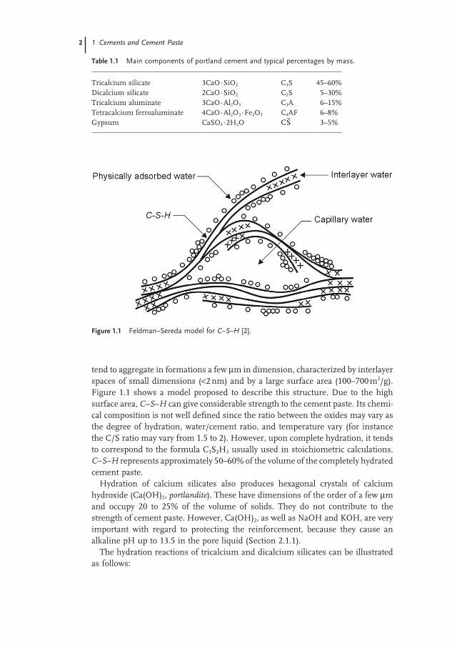
Cements are fine mineral powders that, when they are mixed with water, form a paste that sets and hardens due to hydration reactions. Portland cement is the basis for the most commonly used cements [1–5]. It is produced by grinding clinker, which is obtained by burning a suitable mixture of limestone and clay raw materi-als. Its main components are tricalcium and dicalcium silicates (C3S and C2S),1) the aluminate and ferroaluminate of calcium (C3A and C4AF, respectively). Gypsum (CS) is also added to clinker before grinding, to control the rate of hydration of alumi-nates. Table 1.1 shows the typical ranges of variation of the constituents of portland cement. Other components, such as sodium and potassium oxides, are present in small but variable amounts.
In the presence of water, the compounds of portland cement form colloidal hydrated products of very low solubility. Aluminates react first, and are mainly responsible for setting, that is, solidification of the cement paste. The hydration of C3A and C4AF, in the presence of gypsum, mainly gives rise to hydrated sulfoa-luminates of calcium. Hardening of cement paste, that is, the development of strength that follows setting, is governed by the hydration of silicates. The hydra-tion of C3S and C2S gives rise to calcium silicate hydrates forming a gel, indicated as C–S–H. It is composed of extremely small particles with a layer structure that
1) In the chemistry of cement, the following abbreviations are used: CaO = C; SiO2 = S; Al2O3 = A; Fe2O3 = F; H2O = H; SO S3 = .
2 1 CementsandCementPaste
tend to aggregate in formations a few μm in dimension, characterized by interlayer spaces of small dimensions (<2 nm) and by a large surface area (100–700 m2/g). Figure 1.1 shows a model proposed to describe this structure. Due to the high surface area, C–S–H can give considerable strength to the cement paste. Its chemi-cal composition is not well defined since the ratio between the oxides may vary as the degree of hydration, water/cement ratio, and temperature vary (for instance the C/S ratio may vary from 1.5 to 2). However, upon complete hydration, it tends to correspond to the formula C3S2H3 usually used in stoichiometric calculations. C–S–H represents approximately 50–60% of the volume of the completely hydrated cement paste.
Hydration of calcium silicates also produces hexagonal crystals of calcium hydroxide (Ca(OH)2, portlandite). These have dimensions of the order of a few μm and occupy 20 to 25% of the volume of solids. They do not contribute to the strength of cement paste. However, Ca(OH)2, as well as NaOH and KOH, are very important with regard to protecting the reinforcement, because they cause an alkaline pH up to 13.5 in the pore liquid (Section 2.1.1).
The hydration reactions of tricalcium and dicalcium silicates can be illustrated as follows:
Figure1.1 Feldman–SeredamodelforC–S–H[2].
Table1.1 Maincomponentsofportlandcementandtypicalpercentagesbymass.
Tricalcium silicate 3CaO·SiO2 C3S 45–60%Dicalcium silicate 2CaO·SiO2 C2S 5–30%Tricalcium aluminate 3CaO·Al2O3 C3A 6–15%Tetracalcium ferroaluminate 4CaO·Al2O3·Fe2O3 C4AF 6–8%Gypsum CaSO4·2H2O 3–5%CS
1.2PorosityandTransportProcesses 3
2 6 33 3 2 3 2C S H C S H Ca OH+ = + ( ) (1.1)
2 42 3 2 3 2C S H C S H Ca OH+ = + ( ) (1.2)
The reaction products are the same, but the proportions are different. The ratio between C–S–H and portlandite, passing from the hydration of C3S to that of C2S changes from 61/39 to 82/18, and the amount of water required for hydration from 23% to 21%. In principle, C2S should lead to a higher ultimate strength of the cement paste by producing a higher amount of C–S–H. Nevertheless, the rate of hydration is much lower for C2S compared with C3S, and the strength of cement paste after 28 days of wet curing is mainly due to C3S. Thus, the larger the amount of C3S in a portland cement, the higher the rate of hydration and strength develop-ment of its cement paste. Increasing the fineness of cement particles can also increase the rate of hydration. The reactions leading to hydration of portland cement are exothermic; hence increasing the rate of hydration also increases the rate of generation of heat of hydration.
1.2PorosityandTransportProcesses
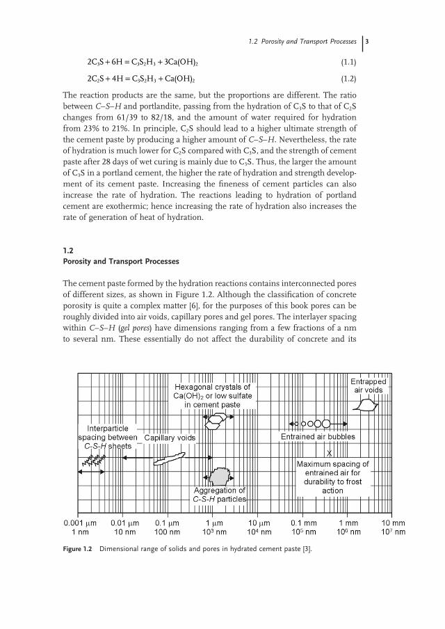
The cement paste formed by the hydration reactions contains interconnected pores of different sizes, as shown in Figure 1.2. Although the classification of concrete porosity is quite a complex matter [6], for the purposes of this book pores can be roughly divided into air voids, capillary pores and gel pores. The interlayer spacing within C–S–H (gel pores) have dimensions ranging from a few fractions of a nm to several nm. These essentially do not affect the durability of concrete and its
Figure1.2 Dimensionalrangeofsolidsandporesinhydratedcementpaste[3].
4 1 CementsandCementPaste
protection of the reinforcement because they are too small to allow significant transport of aggressive species. The capillary pores are the voids not filled by the solid products of hydration within the hardened cement paste. They have dimen-sions of 10 to 50 nm if the cement paste is well hydrated and produced using low water/cement ratios (w/c), but can reach up to 3–5 μm if the concrete is made using high w/c ratios or it is not well hydrated. Larger pores of dimensions of up to a few mm are the result of the air entrapped during mixing and not removed by vibration of fresh concrete. Air bubbles with diameter of about 0.05–0.2 mm may also be introduced in the cement paste intentionally by means of air-entraining admixtures, so as to produce resistance to freeze–thaw cycles (Section 3.1.3). Both capillary pores and entrapped air are relevant to the durability of concrete and its protection of the rebars, since they determine the resistance to the penetration of aggressive species. The main factors affecting the capillary porosity, that is, water/cement ratio, curing, and type of binder, will be briefly analyzed in the following sections. Entrapped air can be reduced by providing adequate workability to the fresh concrete and proper compaction; this is dealt with in Chapter 12.
1.2.1Water/CementRatioandCuring
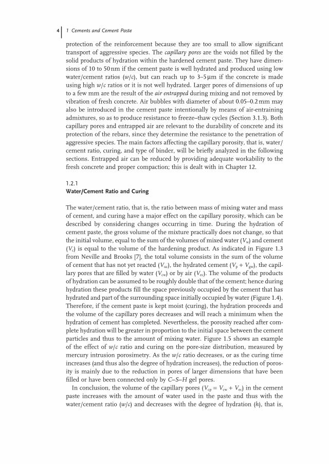
The water/cement ratio, that is, the ratio between mass of mixing water and mass of cement, and curing have a major effect on the capillary porosity, which can be described by considering changes occurring in time. During the hydration of cement paste, the gross volume of the mixture practically does not change, so that the initial volume, equal to the sum of the volumes of mixed water (Vw) and cement (Vc) is equal to the volume of the hardening product. As indicated in Figure 1.3 from Neville and Brooks [7], the total volume consists in the sum of the volume of cement that has not yet reacted (Vuc), the hydrated cement (Vp + Vgw), the capil-lary pores that are filled by water (Vcw) or by air (Vec). The volume of the products of hydration can be assumed to be roughly double that of the cement; hence during hydration these products fill the space previously occupied by the cement that has hydrated and part of the surrounding space initially occupied by water (Figure 1.4). Therefore, if the cement paste is kept moist (curing), the hydration proceeds and the volume of the capillary pores decreases and will reach a minimum when the hydration of cement has completed. Nevertheless, the porosity reached after com-plete hydration will be greater in proportion to the initial space between the cement particles and thus to the amount of mixing water. Figure 1.5 shows an example of the effect of w/c ratio and curing on the pore-size distribution, measured by mercury intrusion porosimetry. As the w/c ratio decreases, or as the curing time increases (and thus also the degree of hydration increases), the reduction of poros-ity is mainly due to the reduction in pores of larger dimensions that have been filled or have been connected only by C–S–H gel pores.
In conclusion, the volume of the capillary pores (Vcp = Vcw + Vec) in the cement paste increases with the amount of water used in the paste and thus with the water/cement ratio (w/c) and decreases with the degree of hydration (h), that is,

1.2PorosityandTransportProcesses 5
Figure1.3 Schematicrepresentationofthevolumetricproportionsincementpastebeforeandduringhydration[7].
Figure1.4 Exampleofmicrostructureofhydratedcementpaste(scanningelectronmicroscope).
6 1 CementsandCementPaste
the fraction of hydrated cement. The effect of w/c and h on the volume of capillary pores (Vcp in liters per kg of cement) can be described by the following formula, proposed by Powers [8]:
V w c hcp /= −( . )0 36 (1.3)
When concrete is considered instead of cement paste, the w/c ratio and degree of hydration remain the main factors that determine the capillary porosity. Neverthe-less, concrete is more complex because of the presence of the aggregates and the interfacial transition zone. The interfacial transition zone is a layer (usually several tens of micrometers thick) of hydrated cement paste in contact with aggregates. Especially for coarse aggregates, the hydrated cement paste in this area is typically heterogeneous and has a higher porosity compared to bulk cement paste [2–4].
Figure1.5 Influenceofthewater/cementratio(a)andcuring(b)onthedistributionofporesizeinhydratedcementpastes[3].
1.2PorosityandTransportProcesses 7
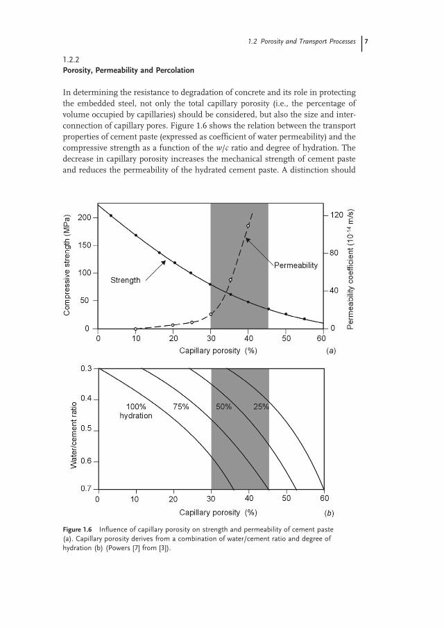
1.2.2Porosity,PermeabilityandPercolation
In determining the resistance to degradation of concrete and its role in protecting the embedded steel, not only the total capillary porosity (i.e., the percentage of volume occupied by capillaries) should be considered, but also the size and inter-connection of capillary pores. Figure 1.6 shows the relation between the transport properties of cement paste (expressed as coefficient of water permeability) and the compressive strength as a function of the w/c ratio and degree of hydration. The decrease in capillary porosity increases the mechanical strength of cement paste and reduces the permeability of the hydrated cement paste. A distinction should
Figure1.6 Influenceofcapillaryporosityonstrengthandpermeabilityofcementpaste(a).Capillaryporosityderivesfromacombinationofwater/cementratioanddegreeofhydration(b)(Powers[7]from[3]).
8 1 CementsandCementPaste
be made between capillary pores of larger dimensions (e.g., >50 nm), or macropo-res, and pores of smaller dimensions, or micropores [3]. The reduction in porosity resulting of both the macro- and the micropores plays an essential role in increas-ing mechanical strength.
On the other hand, the influence of porosity on transport processes cannot be explained simply by the pore volume, the concept of connectivity or the degree of continuity of the pore system also has to be taken into account. At high porosities the interconnected capillary pore system (Figure 1.4) extends from the surface to the bulk of the cement paste. Permeability is high (Figure 1.6) and transport pro-cesses like for example, capillary suction of (chloride-containing) water can take place rapidly. With decreasing porosity the capillary pore system loses its connec-tivity, thus transport processes are controlled by the small gel pores. As a result, water and chlorides will penetrate only a short distance into cement paste. This influence of structure (geometry) on transport properties can be described with the percolation theory [9]: below a critical porosity, pc, the percolation threshold, the capillary pore system is not interconnected (only finite clusters are present); above pc the capillary pore system is continuous (infinite clusters). The percolation theory has been used to design numerical experiments and applied to transport processes in cement paste and mortars [10].
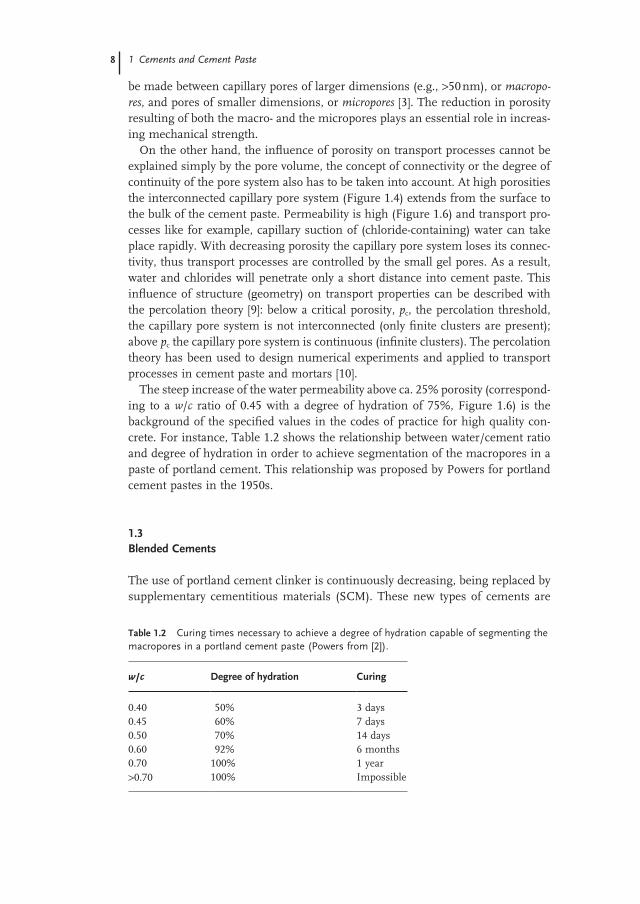
The steep increase of the water permeability above ca. 25% porosity (correspond-ing to a w/c ratio of 0.45 with a degree of hydration of 75%, Figure 1.6) is the background of the specified values in the codes of practice for high quality con-crete. For instance, Table 1.2 shows the relationship between water/cement ratio and degree of hydration in order to achieve segmentation of the macropores in a paste of portland cement. This relationship was proposed by Powers for portland cement pastes in the 1950s.
1.3BlendedCements
The use of portland cement clinker is continuously decreasing, being replaced by supplementary cementitious materials (SCM). These new types of cements are
Table1.2 Curingtimesnecessarytoachieveadegreeofhydrationcapableofsegmentingthemacroporesinaportlandcementpaste(Powersfrom[2]).
w/c Degreeofhydration Curing
0.40 50% 3 days0.45 60% 7 days0.50 70% 14 days0.60 92% 6 months0.70 100% 1 year>0.70 100% Impossible