lte physical layer fundamentals and test requirements · 1.12.2009 · – 3gpp working to define...
TRANSCRIPT

LTE Physical Layer Fundamentals and Test Requirements
Fanny Mlinarsky
octoScope
December 2009

Agenda
• The ‘G’s – brief history of wireless
• Standards organizations– 3GPP, ITU, GCF, PTCRB
• Introduction to LTE– OFDMA, SC-OFDM
– MIMO / Multiple antenna techniques
– UE (user equipment) categories
– FDD, TDD, channelization
• Fading and multipath in the wireless channel
– Standard channel models
• Test methods– R&D, certification, production
3GPP 3rd Generation Partnership Project
ITU International Telecommunication Union
GCF Global Certification Forum
PTCRB PCS Type Certification Review Board

Wire
less
cap
acity
/ th
roug
hput
1970 1980 1990 2000 2010
First cell phones
GSMCDMA
802.11802.16e
LTE
OFDM / OFDMA
WCDMA/HSxPA2G
3G
4GIEEE 802
MIMOBrief History
TACSNMT
AMPS
IS-54IS-136
GPRSAnalog

The G’sG
Peak Data Rate (Mbps)
Downlink Uplink
1 Analog 19.2Kbps
2 Digital – TDMA, CDMA 14.4 Kbps
3Improved CDMA variants (WCDMA, CDMA2000) 144 Kbps (1xRTT);
384 Kbps (UMTS);2.4 Mbps (EVDO)
3.5 HSPA (today) 14 Mbps 5.76 Mbps
3.75HSPA (Release 7) DL 64QAM or 2x2 MIMO; UL 16QAM 28 Mbps 11.5 Mbps
HSPA (Release 8) DL 64QAM and 2x2 MIMO 42 Mbps 11.5 Mbps
4
WiMAX (Release 1.0, TDD 2:1 UL/DL ratio) 10 MHz channel
40 Mbps 10 Mbps
LTE, FDD 5 MHz UL/DL, 2 Layers DL 43.2 Mbps 21.6 Mbps
LTE CAT-3 100 Mbps 50 Mbps
OFDM

OFDM (Orthogonal Frequency Division Multiplexing)
• OFDM is the most robust signaling scheme for a hostile wireless channel– Works well in the presence of multipath thanks to multi-tone signaling and
cyclic prefix (aka guard interval)
• OFDM is used in all new wireless standards, including– 802.11a, g and draft 802.11ac, ad
– 802.16d,e; 802.22
– DVB-T, DVB-H, DAB
• LTE is the first 3GPP standard to adopt OFDM
Multiple orthogonal carriers
MediaFLO = Media Forward Link Only
Volta
ge
Frequency

OFDM for Frequency- and Time-Variable Channel
• OFDM transforms a frequency- and time-variable fading channel into parallel correlated flat-fading channels, eliminating the need for complex equalization
Frequency-variable channel appears flat over the narrow band of an OFDM subcarrier.
Frequency
……
OFDM combined with multiple antenna techniques combats time- and frequency-variability of the wireless channel
Cha
nnel
Qua
lity

OFDMA (Orthogonal Frequency Division Multiple Access)
Frequency
Tim
e
Frequency allocation per user is continuous vs. time
Frequency per user is dynamically allocated vs. time slots
User 1 User 2 User 3 User 4 User 5
Tim
e
OFDM is a modulation
scheme
OFDMA is a modulation and access
scheme

Agenda
• The ‘G’s – brief history of wireless
• Standards organizations– 3GPP, ITU, GCF, PTCRB
• Introduction to LTE– OFDMA, SC-OFDM
– MIMO / Multiple antenna techniques
– UE (user equipment) categories
– FDD, TDD, channelization
• Fading and multipath in the wireless channel
– Standard channel models
• Test methods– R&D, certification, production
3GPP 3rd Generation Partnership Project
ITU International Telecommunication Union
GCF Global Certification Forum
PTCRB PCS Type Certification Review Board
Japan
USA
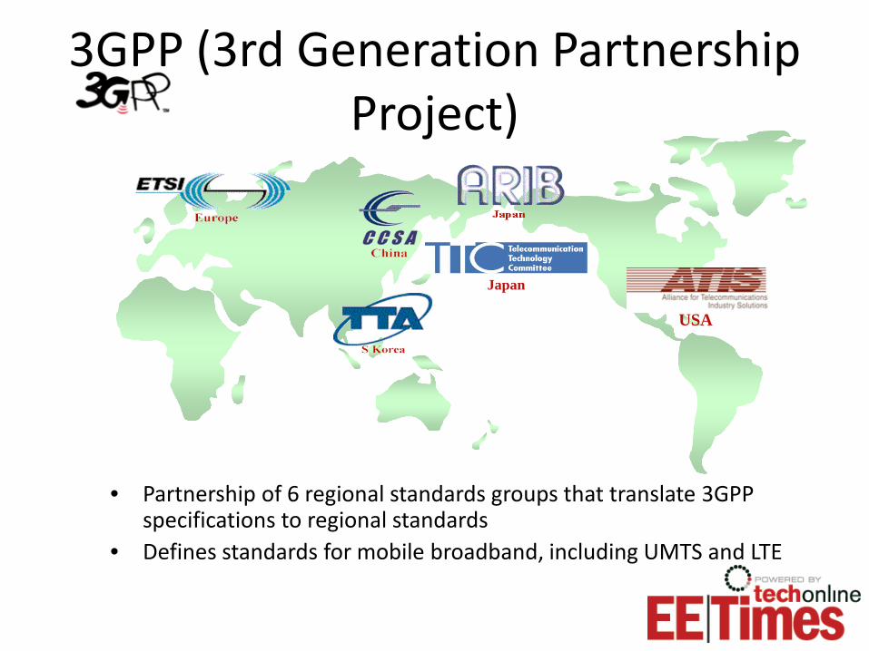
• Partnership of 6 regional standards groups that translate 3GPP specifications to regional standards
• Defines standards for mobile broadband, including UMTS and LTE
3GPP (3rd Generation Partnership Project)

• IMT-2000– Global standard for third generation (3G) wireless communications– Provides a framework for worldwide wireless access by linking the diverse
systems of terrestrial and satellite based networks. – Data rate limit is approximately 30 Mbps – Detailed specifications contributed by 3GPP, 3GPP2, ETSI and others
• IMT-Advanced– New generation framework for mobile communication systems beyond
IMT-2000 with deployment around 2010 to 2015 – Data rates to reach around 100 Mbps for high mobility and 1 Gbps for
nomadic networks (i.e. WLANs)– IEEE 802.11ac and 802.11ad VHT (very high throughput) working to define
the nomadic interface– 3GPP working to define LTE and LTE-Advanced high mobility interface and
so is IEEE 802.16m
ITU International Mobile Telecommunications
ITU = International Telecommunications Union

UMTS UE Certification Bodies
• Global Certification Forum (GCF) is responsible for LTE conformance testing with the focus on European operators
• PCS Type Certification Review Board (PTCRB) provides UE certification for North American operators
• GCF and PTCRB have similar roles but each organization focuses on the frequency bands and regulatory limits relevant to their regions.
• Verizon plans to use GCF for its LTE certification program
www.globalcertificationforum.org
PCS = Personal Communications System, a variation of GSM
www.ptcrb.com

Agenda
• The ‘G’s – brief history of wireless
• Standards organizations– 3GPP, ITU, GCF, PTCRB
• Introduction to LTE– OFDMA, SC-OFDM
– MIMO / Multiple antenna techniques
– UE (user equipment) categories
– FDD, TDD, channelization
• Fading and multipath in the wireless channel
– Standard channel models
• Test methods– R&D, certification, production
3GPP 3rd Generation Partnership Project
ITU International Telecommunication Union
GCF Global Certification Forum
PTCRB PCS Type Certification Review Board

Benefits of LTE/SAE• Increased data rates
– Up to 86 Mbps in the UL, 326 Mbps DL with 4 layers (streams)
• High mobility– Up to 162 km/h (300 Hz Doppler);
standard evolving to support up 500 km/h
• Scalable channel widths– 1.4, 3, 5, 10, 15 and 20 MHz
• Improved spectral efficiency – 2x to 5x, depending on antenna configuration, vs. UMTS
• MIMO, FDD and TDD improve throughput and access efficiency– Part of 3G and LTE
• Flat architecture, lower latency (< 5 ms)– Key for real-time applications such as VoIP, video conferencing, gaming
• Backwards compatibility to legacy networks
• Support for an all-IP network DL = downlink; UL = uplinkSAE = System Architecture Evolution

eNode-B
MME
Serving gateway PDN gateway
Trusted non-3GPP IP Access (CDMA, TD-SCDMA, WiMAX)
Wi-Fi
IP Services (IMS)
GPRS CoreSGSNHSS
PCRF
SGSN (Serving GPRS Support Node)
PCRF (policy and charging enforcement function)
HSS (Home Subscriber Server)
MME (Mobility Management Entity)
PDN (Public Data Network)
Non-3GPP
Trusted
Trusted
Non-Trusted
Flat, low-latency architecture
LTE EPS (Evolved Packet Sys tem)
Access Gateway

Mobility Management
• Mobility Management Entity (MME) is responsible for – UE reachability
– Tracking area
– Inter-eNB mobility (resides in the serving gateway)
• Intra-LTE handovers
– Inter-3GPP mobility• Handovers between 3GPP 2G/3G
access systems and LTE
Serving cell
Non-serving cell
SchedulingRate adaptationHARQData transmissions
Quality of Service (QoS)
• Radio Resource Management (RRM)– Establishes, maintains and releases radio bearers
– Dynamically allocates resources for sending data over the airlink
– Manages RBs for minimum inter-cell interference
– Load balancing: re-distributes traffic loads among multiple cells
– Inter-RAT RRM manages inter-RAT handovers
• QoS is defined (3GPP document 22.278) for– Network access
– Service access
– Service retainability
– Service integrity
RAT = radio access technology

DLUL
DL
UL
FDD and TDD Support• FDD (frequency division duplex)
– Paired channels
• TDD (time division duplex)– Single frequency channel for uplink an downlink
– Is more flexible than FDD in its proportioning of uplink vs. downlink bandwidth utilization
– Can ease spectrum allocation issues
TDD
FDD

FDD and TDD Frame Structures
1 slot = 0.5 ms = 15360*Ts, Ts = 32.5 ns
1 subframe = TTI
1 radio frame, 10 ms
5 ms
DwPTSGP
UpPTS DwPTSGP
UpPTS
0 2 3 4 5 7 8 9
DwPTS = Downlink Pilot Time slotUpPTS = Uplink Pilot Time SlotGP = Guard PeriodTTI = Transmission Time Interval
10 11 12 13 14 15 16 17 18 190 1 2 3 4 5 6 7 8 9
TDD Frame Structure, Type 2
FDD Frame Structure, Type 1

TDD Mode
Config # Subframe number
0 1 2 3 4 5 6 7 8 9
0 DL UL UL UL DL UL UL UL
1 DL UL UL DL DL UL UL DL
2 DL UL DL DL DL UL DL DL
3 DL UL UL UL DL DL DL DL
4 DL UL UL DL DL DL DL DL
5 DL UL DL DL DL DL DL DL
6 DL UL UL UL DL UL UL DL
TDD Frame, Type 2Subframe
0 2 3 4 5 7 8 9
5 ms

User 1
User 2
User 3 User 1
User 3
User 3
User 2
User 2
User 1
User 3
User 2
User 2
User 1
User 1
User 3
User 3
User 2
User 2
User 2
User 1
Frequency
Tim
e
Resource Block (RB)
180 kHz, 12 subcarriers with normal CP
0.5 ms7 symbols with normal CP
Resource Allocation
• Resources are allocated per user in time and frequency. RB is the basic unit of allocation.
• RB is 180 kHz by 0.5 ms; typically 12 subcarriers by 7 OFDM symbols, but the number of subcarriers and symbols can vary based on CP
CP = cyclic prefix, explained ahead

Resource Block
1 slot, 0.5 ms
1 subcarrierResource Element1 subcarrierQPSK: 2 bits16 QAM: 4 bits64 QAM: 6 bits
Resource block 12 subcarriers
Time
Sub
carr
ier (
frequ
ency
)
…
…
……v
A resource block (RB) is a basic unit of access allocation. RB bandwidth per slot (0.5 ms) is12 subcarriers times 15 kHz/subcarrier equal to 180 kHz.

Center subcarrier (DC) not transmitted in DL
Transmission bandwidth in RBs
Channel bandwidth in MHz
1.4 3 5 10 15 20
1.08 2.7 4.5 9 13.5 18
6 15 25 50 75 100
Channel bw
Transmission bw
# RBs per slot
MHz
Scalable Channel Bandwidth
Guard band

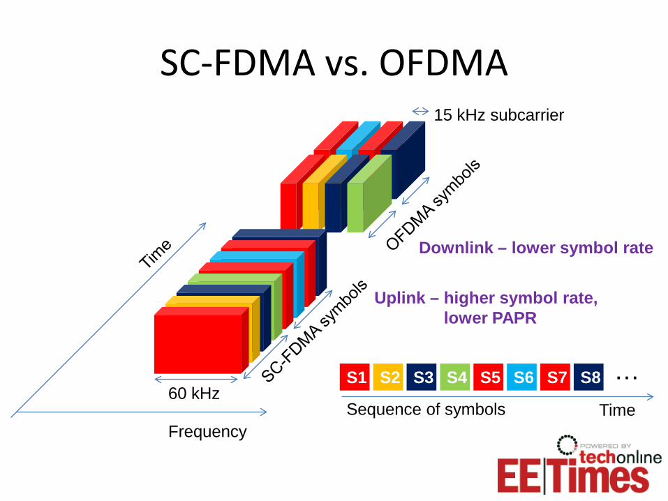
OFDMA vs. SC-FDMA
• Multi-carrier OFDM signal exhibits high PAPR (Peak to Average Power Ratio) due to in-phase addition of subcarriers.
• Power Amplifiers (PAs) must accommodate occasional peaks and this results low efficiency of PAs, typically only 15-20% efficient. Low PA efficiency significantly shortens battery life.
• To minimize PAPR, LTE has adapted SC-FDMA (single carrier frequency division multiple access) in the uplink. SC-FDMA exhibits 3-6 dB less PAPR than OFDMA.
In-phase addition of sub-carriers creates peaks in the OFDM signal
Sequence of symbols
S1 S2 S3 S4 S5 S6 S7
Time
S8
Frequency
15 kHz subcarrier
60 kHz
Uplink – higher symbol rate, lower PAPR
Downlink – lower symbol rate
SC-FDMA vs. OFDMA
…

N-point IDFT
Subcarrier mapping
M-point DFT
Serial to Parallel
SC constellation map
Parallel to Serial
CP removal
N-point DFT
Subcarrier de-mapping
M-point IDFT
Parallel to Serial
Detect
Serial to Parallel
TX bit stream RX bit stream
SC-FDMA only
CP & pulse shaping
OFDMA and SC-FDMA
Radio Block Diagram
A/D, D/A converters RF Front End

Cyclic Prefix
• After IDFT and parallel to serial conversion, the composite symbol is extended by repeating the end of the symbol in the beginning. This extension is called the Cyclic Prefix (CP).
• CP is a guard interval that allows multipath reflections from the previous symbol to settle prior to receiving the current symbol. CP has to be greater than the delay spread in the channel.
• CP eliminates Intersymbol Interference (ISI) and makes the symbol easier to recover.
TS
copy
Guard interval > delay spread in the channelUseful data

Forward Error Correction and Hybrid Automatic Repeat reQuest
• LTE uses– Turbo Convolutional Coding
– AMC (Adaptive Modulation Coding)
– Type II Hybrid Automatic Repeat reQuest (HARQ)
• For time-varying channels, an adaptive scheme such as the Incremental HARQ is used– Codeword is subsequently punctured and
transmitted over the channel until it is successfully delivered to the receiver.
– Successive interference cancellation
Time
TX0TX1
NACKACK
TX0TX2
HARQ process

Multiple Antenna Techniques
• SISO (Single Input Single Output)– Traditional radio
• MISO (Multiple Input Single Output)– Transmit diversity
– Space Frequency Block Coding (SFBC) or Cyclic Delay Diversity (CDD)
• SIMO (Single Input Multiple Output)– Receive diversity
– Maximal Ratio Combining (MRC)
• MIMO (Multiple Input Multiple Output)– Spatial Multiplexing (SM) to transmit multiple layers (streams)
simultaneously; can be used in conjunction with Cyclic Delay Diversity (CDD); works best in high SINR environments and channels de-correlated by multipath
– TX and RX diversity, used independently or together; used to enhance throughput in the presence of adverse channel conditions

Multiple Antenna Precoding
• Codeword (CW0, CW1) is a block of data
• For Spatial Multiplexing (SM) 2 to 4 layers (streams) can transmitted
• The process of precoding is used to format layers for TX diversity (CDD, SFBC), SM or beamsteering
SFBC = Space Frequency Block CodingCDD = Cyclic Delay Diversity

Receive and Transmit Diversity
• Receive diversity, MRC, makes use of the highest signal quality, combining signals from both antennas
• Transmit diversity techniques, CDD or SFBC, spread the signal so as to create artificial multipath to decorrelate signals from different antennas with the goal of delivering a peak on one receive antenna while there may be a null on another.
Peak
Null

Single-, Multi-User MIMO
• MU-MIMO allows two UEs to share RBs provided their channels to the eNB are sufficiently decorrelated.
• MU-MIMO increases uplink capacity.
• SU-MIMO requires a UE to have two transmitters, which is currently considered detrimental to battery life and cost

LTE Multi-Antenna Configurations• eNB TX antennas: 1, 2 or 4
• UE RX antennas: 2 or 4 for MRC
• DL TX diversity: SFBC (space frequency block coding); TDD
• DL SM (spatial multiplexing): codebook-based precoding; up to 2 parallel codewords
• Closed loop MIMO is used for beamforming– Requires channel sounding and exchange of
channel response between the UE and eNB

Maximum Raw Uplink Data Rate1 TX
Total bandwidth 20 MHz
Total Resource Blocks 100
Resource Elements per Resource Block 84
Resource Element overhead (uplink reference signals) 12Available Resource Elements per Resource Block (after
overhead)72
Resource Elements per Resource Block pair (in 1 ms) 144Total Resource Elements available per subframe 14400
Bits per Resource Element, 64 QAM 6Total bits per subframe 86400
Raw Channel Bandwidth 86.4 Mbps
Source: http://www.lteuniversity.com/blogs/chrisreece/archive/2009/08/04/the-magic-86.aspx

Maximum Raw Downlink Data Rate2x2 MIMO 4x4 MIMO
Total bandwidth 20 MHz 20 MHzTotal Resource Blocks 100 100
Resource Elements per Resource Block 84 84Resource Elements per Resource Block pair 168 168
Resource Element Overhead – PDCCH (Assuming only one OFDM symbol for PDCCH)
12 12
Resource Element Overhead - Reference Signals 12 20Resource Elements per Resource Block pair (in 1 ms) 144 136
Total Resource Elements available per subframe 14400 13600Bits per Resource Element (64 QAM) 6 6
Total bits per subframe 86400 81600Throughput per layer 86.4 Mbps 81.6 Mbps
Throughput for 2x2 MIMO, 2 layers (streams) 172.8 Mbps
Throughput for 4x4 MIMO, 4 layers (streams) 326.4 Mbps
Source: http://www.lteuniversity.com/blogs/chrisreece/archive/2009/08/04/the-magic-86.aspx

UE Categories 1-5
Category DL/UL data rates (top uplink modulation)
Multiple Antenna eNB TX x UE RX
Cat 1 10/5 Mbps (16QAM) 1 x 2
Cat 2 51/25 Mbps (16QAM) 2 x 2
Cat 3 102/51 Mbps (16QAM) 2 x 2
Cat 4 150/51 Mbps (16QAM) 2 x 2
Cat 5 302/75 Mbps (64QAM) 4 x 4
Source: 36.306
• 64QAM only used by Category 5 UE
• Assumption: Ideal channel conditions with optimum coding rate (approximately .98)

LTE Transmission Modes
Transmission mode
1 Single-antenna; port 0
2 Transmit diversity
3 Open loop spatial multiplexing
4 Closed loop spatial multiplexing
5 MU-MIMO
6 Closed loop rank=1 precoding
7 Single-antenna; port 5
Source: 3GPP document 36.213

Dynamic Nature of the LTE Radio
• Resources, coding and multiple antenna techniques are dynamically varied by the LTE radio in response to time-variable channel conditions
• MAC – Multiplexes data from logical channels to
transport blocks on the transport channels
– Performs error correction through HARQ
– eNB MAC dynamically allocates RBs among UEs
– Channel Quality Indicators (CQI) reported form the UE to the eNB are used for scheduling decisions
MAC = medium access control

Channel State Information (CSI) Uplink Control Signaling
• CQI (channel quality indicator)– Computed at the UE for each codeword based
on SINR (signal to interference and noise ratio)
– Wideband CQI is computed for the entire channel
– CQI can also be computed for groups of RBs
• RI (rank indicator)– Represents the number of layers to be used in
the next downlink transmission
• PMI (precoding matrix indicator)– Index to the preferred precoding matrix to
optimize MIMO operation
CSI indicators are computed by the UE and reported to eNB for resource allocation decision making by the eNB MAC and higher layers

Band Uplink (UL) Downlink (DL) Regions1 1920 -1980 MHz 2110 - 2170 MHz Europe, Asia2 1850 -1910 MHz 1930 - 1990 MHz Americas, Asia3 1710 -1785 MHz 1805 -1880 MHz Europe, Asia, Americas4 1710 -1755 MHz 2110 - 2155 MHz Americas5 824-849 MHz 869 - 894 MHz Americas
6 830 - 840 MHz 875 - 885 MHz Japan 7 2500 - 2570 MHz 2620 - 2690 MHz Europe, Asia8 880 - 915 MHz 925 - 960 MHz Europe, Asia9 1749.9 - 1784.9 MHz 1844.9 - 1879.9 MHz Japan
10 1710 -1770 MHz 2110 - 2170 MHz Americas
11 1427.9 - 1452.9 MHz 1475.9 - 1500.9 MHz Japan
12 698 - 716 MHz 728 - 746 MHz Americas
13 777 - 787 MHz 746 - 756 MHz Americas
14 788 - 798 MHz 758 - 768 MHz Americas17 704 - 716 MHz 734 - 746 MHz
LTE Frequency Bands - FDD
Source: 3GPP TS 36.104 V8.4.0 (2008-12)

LTE Frequency Bands - TDDBand UL and DL Regions
33 1900 - 1920 MHz Europe, Asia (not Japan)34 2010 - 2025 MHz Europe, Asia35 1850 - 1910 MHz 36 1930 - 1990 MHz 37 1910 - 1930 MHz 38 2570 - 2620 MHz Europe39 1880 - 1920 MHz China40 2300 – 2400 MHz Europe, Asia
Source: 3GPP TS 36.104 V8.4.0 (2008-12)

Agenda
• The ‘G’s – brief history of wireless
• Standards organizations– 3GPP, ITU, GCF, PTCRB
• Introduction to LTE– OFDMA, SC-OFDM
– MIMO / Multiple antenna techniques
– UE (user equipment) categories
– FDD, TDD, channelization
• Fading and multipath in the wireless channel
– Standard channel models
• Test methods– R&D, certification, production
3GPP 3rd Generation Partnership Project
ITU International Telecommunication Union
GCF Global Certification Forum
PTCRB PCS Type Certification Review Board

• Time-varying FIR filter weights– Spatially correlated: H11 correlated with H12, etc., according to antenna spacing
– Doppler fading
H 11
H 22
Transmitter Receiver
Multipath Fading MIMO Channel

LTE Channel Models
• 3GPP TR 25.996 v6.1.0 (2003-09) defines dynamic fading models with multipath and correlations– Spatial Channel Model (SCM)
– 9 taps, max tap delay 5000 ns
– Models derived from ITU M.1225
• Each tap represents a reflection (or a path); multiplier coefficients are dynamically changing to model Doppler shift, angle of arrival and angle of departure
• Number of fading channels is number of TX times number of RX
H ijFading channel

Industry Standard Channel Models Model Description Document
ITU Ped-B, Veh-A Recommendation ITU-R M.1225, Guidelines for Evaluation of Radio Transmission, Technologies for IMT-2000, 1997
Indoor Hotspot, Urban Macro, UrbanMicro, Rural Macro, Sub-urban Macro
ITU-R Report M.2135, Guidelines for evaluation of radio transmission technologies for IMT-Advanced, 2008
WiMAX AWGN, ITU Ped-B, Veh-A,Modified Veh-A for 10 usec impulse response and 120 km/hr
WiMAX Forum Mobile RCT XX xxx xxx v2.2.0, Appendix 4
LTE Extended Pedestrian A model (EPA)Extended Vehicular A model (EVA)Extended Typical Urban model (ETU)
3GPP 36-521, UE Conformance Specification,Annex B
IEEE 802.11n Models A-F IEEE 11-03-0940-04-000n-tgn-channel-models
Bypass Identity matrix or butler matrix
Doppler Spectrum
Classical Jakes, Bell shaped, Bell + Spike (802.11n)
Fading Rayleigh, Ricean
44

Agenda
• The ‘G’s – brief history of wireless
• Standards organizations– 3GPP, ITU, GCF, PTCRB
• Introduction to LTE– OFDMA, SC-OFDM
– MIMO / Multiple antenna techniques
– UE (user equipment) categories
– FDD, TDD, channelization
• Fading and multipath in the wireless channel
– Standard channel models
• Test methods– R&D, certification, production
3GPP 3rd Generation Partnership Project
ITU International Telecommunication Union
GCF Global Certification Forum
PTCRB PCS Type Certification Review Board

Typical UE Test Configuration• Typical UE test configuration for a variety of tests, including:
– R&D
– IOT (interoperability)
– PCT (protocol conformance test)
• … incorporates a base station emulator and a fading channel simulator
UE under test can interface to the eNB emulator via RF front end or digital IQ
Anritsu MF6900A fading simulator
Anritsu MD8430A eNB emulator

Base Station Emulator Requirements
• Support 2G, 3G and 4G to test multi-mode UEs– GSM/GPRS/E-GPRS; W-CDMA/HSxPA; LTE
– HSDPA up to 28 Mbps; HSUPA up to 11.5 Mbps for Release 7; provide upgrade path to Release 8
– LTE Category 3 support for 100/50 Mbps (DL/UL) is important today; Category 4 support is desirable
– FDD and TDD support
– Frequency range should accommodate all common channels
• Support 2x2 MIMO handover between 3G and 4G

Dynamic Multi Base Station Tests• Some eNB emulators can emulate multiple logical eNBs
– E.g. Anritsu MD8430A can emulate 6 Cells
• Emulated eNB should be able to react to CSI from the UE (CQI, PMI and RI) to adjust MAC scheduling, including RBs, modulation and multiple antenna configurations.
Anritsu MD8430AeNB emulator
CSI = channel state informationCQI = channel quality indicatorPMI = precoding matrix indicatorRI = rank indicator

LTE UE Tests• LTE UE testing includes a large number of test configurations. Configurations
should include support for: – 5, 10, 15 and 20 MHz bands
– UE categories 1-4
– Up to 2x2 MIMO
– Periodic, aperiodic and closed loop CQI, PMI, RI
– Variety of handover scenarios
– UL sequence and frequency hopping
– All the required DCI formats
– DL distributed VRB (virtual RB)
– MU-MIMO
– Scheduling
– TTI bundling
– HARQ
• The above are just examples. Total number of features and configurations is extremely large due to the considerable complexity of the LTE standards.

Handover Testing
• Base station emulators, such as Anritsu MD8430A (LTE) or MD8480C (3G) are used with automated software, such as RTD to set up the conditions for inter-RAT or intra-RAT handover and verify UE behavior in a variety of handover scenarios and channel conditions
LTE/UTRAN/GERAN UE under test
LTE Simulation(3GPP Release 8)
UTRAN/GERAN Simulation(3GPP Release 7 or before)
MD8430A
MD8480C
RTD console
Combined LTE/UTRAN/GERAN Test

Complete System TestAnritsu Rapid Test Designer
(RTD)
Anritsu MD8430 eNodeB simulator
Anritsu MD8480C NodeB simulator(s)
Power Combiner Sw
itch
Network Switch
AnritsuMF6900A FadingSimulator
LVDS
LVDS
TE Port
TE Port
LTE/UTRAN/GERAN UE
Test network
Measure throughput performance in the presence of fading and multipath and during handovers

Test Automation
• Powerful test automation is critical due to complexity of test and the number of test cases.
• Meet 3GPP TS 27.007
Cell Simulator
UE
Test Executive
TestScript
Control Messages
RF
CLI (Command Line Interface) to provide automation from within a test system
AT-MMI Commands to control the DUT
Comprehensive test reports
AT = ATtentionMMI = Man-Machine Interface

Network Model
• Base station emulation equipment should be configurable to a variety of network models, including:– Individual cell definitions with cell-
specific parameters
– Definition for groups of cells with inter-dependent parameters
f1PLMN-001-01
LAC 0002RAC 02NMO-IIS/C 28
Cell Id - 2
f1PLMN-002-01
LAC 0004RAC 04NMO-IIS/C 31
Cell Id - 4
f5BSIC 000-000PLMN-001-01
LAC 0009RAC 09NMO-I
Cell Id - 9
f1PLMN-001-01
LAC 0001RAC 01NMO-IS/C 6
Cell Id - 1
3 Cell UMTS (Intra-Frequency) + 1 Cell GSM
Network model example

Conformance Testing• Conformance test system
should– Support the GCF and PTCRB
requirements for conformance testing and offer pre-programmed GCF/PTCRB approved test cases
– Come preconfigured with various instruments and dedicated software implementing the test suites
– Support automated sequencing of tests, allowing long measurements to run unattended GCF (Global Certification Forum) is responsible for
certifying conformance to standards for UE and test systems. GCF is composed mainly of European members and performs certification for frequency bands used in Europe.
Pass/Fail indicators
PTCRB (PCS Type Certification Review Board) is a similar test system certification organization to GCF composed mainly of North American members and performing conformance certification for frequency bands used in North America

Test Complexity and Need for Test Automation
• Enormous complexity of 3GPP protocol testing calls for test automation.
• The best automation tools are expert systems, incorporating high level calls to detailed test cases and guiding the user through the complexity of the LTE protocol– Should not require knowledge of TTCN– Should provide expedient programming of
emulation (base station and fading channel emulators) and measurement instruments (signal generators and signal analyzers)
Anritsu RTDFlow chart level coding replaces TTCN
RTD = Rapid Test DesignerTTCN = Testing and Test Control Notation version

Production Testing of UE• Speed and accuracy are
key for production test
• Focus is on transmitter and receiver tests– RF adjustments and
parametric tests using the test mode of the DUT
• Ability to test two UEs in parallel improves manufacturing efficiency and reduces production costs
Anritsu MT8820B
RF cables
Signal generator and signal analyzer

Concluding Thoughts• LTE standards and technology
incorporate the latest innovations in wireless communications, including– OFDMA
– MIMO
– Dynamic resource allocation, antenna configurations and other settings
– Channel width flexibility
– Mobility management
– Low latency IP networking
– Backwards compatibility
• As a result, the LTE standards are extremely complex.
• Complex technology does not work well unless it is well-tested.
Thorough testing is key to making LTE
successful in the market.

Learn More• For more valuable LTE information, download Anritsu's newly
released LTE Resource Guide and White Paper– http://www.anritsuco.com/LTE/offers.htm?utm_source=TechOnline&utm_medium
=eCourse&utm_campaign=TechOnline%2BFundamentals%20Nov%202009
• Visit us on the web at www.anritsu.com
www.octoscope.com