lte architecture and interfaces
TRANSCRIPT

LTE Architecture & Interfaces Prepared By: RF Team
AbdelRahman Fady & Mohamed Mohsen

Course Contents
• Historical vision
• LTE Capabilities
• System architecture

General Revision 3GPP and IEEE evolutions

3GPP evolution • 1G (Early 1980s)
– Analog speech communications.
– Analog FDMA.
– Ex: AMPS
• 2G: Started years ago with GSM: Mainly voice
– – Digital modulation of speech communications.
– – Advanced security and roaming.
– – TDMA and narrowband CDMA.
– – Ex: GSM, IS-95 (cdmaOne), and PDC
• 2.5G: Adding Packet Services: GPRS, EDGE
• 3G: Adding 3G Air Interface: UMTS
• 3G Architecture: • Support of 2G/2.5G and 3G Access
• Handover between GSM and UMTS technologies
• 3G Extensions: • HSDPA/HSUPA
• IP Multi Media Subsystem (IMS)
• Inter-working with WLAN (I-WLAN)
• Beyond 3G: • Long Term Evolution (LTE)
• System Architecture Evolution (SAE)
• Adding Mobility towards I-WLAN and non-3GPP air interfaces

3GPP2 evolution
• CDMA2000 1X (1999) • CDMA2000 1xEV-DO (2000)
• EV-DO Rev. A (2004): VoIP
• EV-DO Rev. B (2006): Multi-carrier
• Ultra Mobile Broadband (UMB), f.k.a. EV-DO Rev.C
– Based on EV-DO, IEEE 802.20, and FLASH-OFDM – Spec finalized in April 2007. – Commercially available in early 2009.

IEEE 802.16 Evolution
• 802.16 (2002): Line-of-sight fixed operation in 10 to 66 GHz
• 802.16a (2003): Air interface support for 2 to 11 GHz • 802.16d (2004): Minor improvements to fixes to 16a • 802.16e (2006): Support for vehicular mobility and asymmetrical link • 802.16m (in progress): Higher data rate, reduced
latency, and efficient security mechanism

Beyond 3G • International Mobile Télécommunications (IMT)-2000 introduced global standard for 3G. • Systems beyond IMT-2000 (IMT-Advanced) is set to introduce evolutionary path beyond 3G. • Mobile class targets 100 Mbps with high mobility and nomadic/ local area class targets 1 Gbps with low mobility. • 3GPP and 3GPP2 are currently developing evolutionary/ revolutionary systems beyond 3G.
– 3GPP Long Term Evolution (LTE) – 3GPP2 Ultra Mobile Broadband (UMB)
• IEEE 802.16-based WiMax is also evolving towards 4G through 802.16m.

Beyond 3G • Release 99 (Mar. 2000): UMTS/WCDMA
• Rel-5 (Mar. 2002): HSDPA
• Rel-6 (Mar. 2005): HSUPA
• Rel-7 (2007): DL MIMO, IMS (IP Multimedia Subsystem), optimized real-time services (VoIP, gaming, push-to-talk). • Long Term Evolution (LTE) – 3GPP work on the Evolution of the 3G Mobile System started in November 2004. – Standardized in the form of Rel-8. – Spec finalized and approved in January 2008. – Target deployment in 2010. • LTE advanced

Course Contents
• Historical Vision
• LTE Capabilities
• System architecture

Beyond 3G 3G evolution

Why LTE ……?
• Need for PS optimized system • Evolve UMTS towards packet only
system
• Need for higher data rates • Can be achieved with HSDPA/HSUPA • and/or new air interface defined by
3GPP LTE
• Less processor load cost • Less number of transitions between
different states will lead definitely to less processor load
• Need for high quality of services • Use of licensed frequencies to
guarantee quality of services • Always-on experience (reduce control
plane latency significantly) • Reduce round trip delay (→ 3GPP LTE)
• Need for cheaper infrastructure • Simplify architecture, reduce number

LTE Defined Data Rates
• Downlink
– 100Mbps theoretical
• Uplink
– 50Mbps theoretical
• Generally we can say the downlink rate relative to HZ 5 bits/s/HZ and for Uplink 2.5bits/s/HZ

LTE duplexing and accessing
• Duplexing Methods
– FDD
• UL and DL can reach the peak traffic simultaneously
– TDD
• UL and DL can not reach the peak traffic simultaneously
• Accessing techniques
– OFDMA for the DL
– SC-FDMA for the UL

Modulation and coding
• Adaptive Modulation and Coding
– DL Modulations: QPSK, 16-QAM and 64-QAM modulation
– UL Modulations: QPSK and 16-QAM
– Turbo code

LTE Maximum Latency (1-2)
• For control Plane
– The delay of changing the mobile mode from the active to non active and vice versa
• If the terminal was in the idle mode it needs 100msec
• If the terminal was in the dormant it needs 50msec
• For User Plane
– Time the terminal takes to transmit small packets to the RAN and Vice versa is 5 msec

LTE Maximum Latency (2-2)
• What is the idle mode
– Terminal unknown for the RAN
– No Radio resources assigned
• What is the dormant mode
– Terminal is known for the RAN
– No Radio resources assigned

LTE theoretical Capacity
• Active Mode – At 5MHZ BW the Cell can
support 200 users simultaneously.
– At BW more than 5 MHZ the Cell can support up to 400 Simultaneously terminal.
• IDLE Mode – Can support more than 400
Users at the same time

LTE System Performance targets(1-2)
• User throughput
– 95% from the users will take average throughput
– 5% will be little bit smaller than the average
• Spectrum efficiency – It define high spectrum
efficiency Bits/MHZ/Cell
• Coverage – 5 Km with high throughput – 30 Km with low throughput – 100Km with very low
throughput

LTE System Performance targets(2-2)
• Mobility – 0-15km/ hour the more
better subscriber behavior.
– 120 km/ hour the accepted behavior.
– 350 km/ hour very low data rate and data throughput.
• Enhanced MBMS – Up to 16 multimedia
channels per just one carrier

LTE deployment aspects
• Flexible spectrum – The carrier could be 1.25
MHZ , 1.6 MHZ, 2.5 MHZ ,5MHZ , 10MHZ , 15MHZ or 20 MHZ
– Can use the IMT2000 Band • 1910-1920 and 2010-2025 are
the TDD Band • 1920- 1960 FDD UL and 2110-
2170 FDD DL
• Stand alone • Coexisted with WCDMA and
GSM – HO from LTE to GSM 500msec
for NRT and 300 for RT and the same for GSM

• LTE Frequency Reuse Pattern
– Generally it is equal to 1
– IIC (Inter cell interference coordinator) is used to reduce the interference and make the reuse for cell outer area > 1
Interference handling

Architecture and Migration
• LTE RAN agreed on the following – Packet bearer support
• Real Time • Conversational
– Reduce the number of the new interfaces
– NO RNC – NO CS-CN
– Reduce the single point of failure – NO RNC
– Separate the treatment of different types of traffic (O&M, Control and Data) to utilize the BW
– Reduce the variable delay and Jitter (TCP/IP)
– Agreed QOS between Transmitting end and receiving end
– No SHO or Macro diversity – MIMO and Tx diversity techniques
used

Complexity
• Easy design
• Less complex
• No redundant feature
• Minimize Cost and maintain system performance
– Low complexity
– Low power consumption

LTE Services (1-2)

LTE Services (2-2)

Course Contents
• Historical Vision
• LTE Capabilities
• System architecture

Network architecture Evolution

3GPP-LTE Architecture High level (1-2)

3GPP-LTE Architecture High level (2-2)
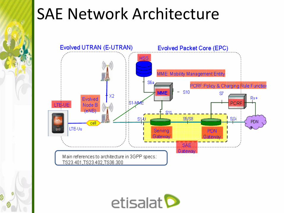
SAE Network Architecture

Evolved UTRAN

EPC (1-5)

EPC (2-5)

EPC (3-5)

EPC (4-5)

EPC (5-5)

Interfaces

UTRAN interfaces

EPC Interfaces ( 1 – 5 )

EPC Interfaces ( 1 – 5 )

EPC Interfaces ( 2 – 5 )

EPC Interfaces ( 3 – 5 )

EPC Interfaces ( 4 – 5 )

EPC Interfaces ( 5 – 5 )

Interworking Architecture (1 – 4)

Interworking Architecture Interworking Architecture (2 – 4)

Interworking Architecture Interworking Architecture (3 – 4)

Interworking Architecture Interworking Architecture (4 – 4)

Roaming Architecture (1 - 3)

Roaming Architecture (2 - 3)

Roaming Architecture (3 - 3)

Overall LTE system Architecture

Thank You